Embed Size (px)
Citation preview
Design and Construction Manual for Water Supply and Sanitation Facilities in Primary Schools
i
This manual is a revised version of the first publication, 2010. The major input into this edition is the inclusion of water supply for schools in more detail, improved latrine designs for pastoralists taking into account their religious and cultural norms and values and enriching earlier designs with more information for schools. This edition is prepared under the technical guidance and supervision of UNICEF Ethiopia and in collaboration with the three Ministries; Ministry of Health, Ministry of Education and Ministry of Water and Energy. The consulting firm has visited and assessed Somali, Amhara and SNNP Regions and valuable feedback and recommendations have been received on their experiences on the first edition.
Design and Construction Manual for Water Supply and Sanitation Facilities in Primary Schools
ii
Acknowledgment The consultant Firm would like to express its appreciation to the Ministry of Health, Ministry of Education and Ministry of Water and Energy and UNICEF Ethiopia for making possible the production of the revised version of the School WASH Manual. Several people have contributed towards the production of this manual. On behalf of the Consultant Firm, we would like to acknowledge and thank the following: Mr. Paul Devriell, Mrs. Blinda Abraham and Dr. Daniel Gelan from UNICEF Ethiopia, and Dr. Gezahagne Ayele, Alemayehu Bisrat, Ato Fikru Tessema, Ato Erkyhun Desta and Ato Shawel Astatke as member of the consultant team during the first and second assignments. Special thanks go to Mr. Paul Devreill for providing technical support and guidance for the consultant team throughout their assignment. He has also edited the whole manuscript to its present form. Thanks are also due to those experts of regional water, health and education bureaus who have been contacted by the consultants during the field missions for consultation and feedback, and their valuable inputs made this manuscript reached to its present form and we appreciate for that. Getachew Alem Principal Consultant Getachew Alem & Associates
Design and Construction Manual for Water Supply and Sanitation Facilities in Primary Schools
iii
Abbreviations CHB Concrete Hollow Block
CIS Corrugated Iron Sheet
cm Centimeter
FDRE Federal Democratic Republic of Ethiopia
GS Galvanized Steel
ISO International Standard Organization
IWRM Integrated Water Resources Management
kg kilogram
mm Millimeter
MoEd Ministry of Education
MoH Ministry of Health
MoWE Ministry of Water and Energy
NGO Non Governmental Organization
O&M Operation and Maintenance
PTA Parent Teachers Association
PV Photo Voltaic
PVC Polyvinyl Chloride
RC Reinforced Concrete
RET Renewable Energy Technology
SNNPR Southern Nations and Nationalities Peoples Region
UN United Nation
UNICEF United Nations Children Fund
VIP Ventilated Improved Pit
WASH Water, Sanitation and Hygiene
WHO World Health Organization

Design and Construction Manual for Water Supply and Sanitation Facilities in Primary Schools
iv
Preface

Design and Construction Manual for Water Supply and Sanitation Facilities in Primary Schools
v
TABLE OF CONTENTS
PAGE
ACKNOWLEDGMENT .................................... ..................................................................................................... II
ABBREVIATIONS ..................................... ........................................................................................................... III
PREFACE ............................................................................................................................................................. IV
SECTION 1: INTRODUCTION ............................................................................................................................. 1
1.1 SCHOOL WATER SUPPLY, SANITATION AND HYGIENE (WASH) FACILITIES IS A PRIORITY ......1 1.2 SCOPE OF THE MANUAL ..............................................................................................................2 1.3 FOR WHOM THE MANUAL IS FOR ..................................................................................................3
1.4 STRUCTURE OF THE MANUAL ......................................................................................................3
1.5 PRINCIPLES FOR THE DESIGN AND CONSTRUCTION OF WASH FACILITIES ................................4
SECTION II: WATER SUPPLY FOR SCHOOLS .............. .................................................................................. 7
2.1 INTRODUCTION .............................................................................................................................7 2.2 MAJOR WATER SUPPLY SYSTEMS ..............................................................................................7
2.2.1 School Rooftop Water Harvesting ...................................................................................1
2.2.2 Groundwater Sources........................................................................................................2
SECTION III: DESIGN AND CONSTRUCTION OF WATER SUPPLY FACILITIES ........................................ 2
3.1 INTRODUCTION .............................................................................................................................2 3.2 WATER DEMAND ..........................................................................................................................2 3.3 WATER SUPPLY SYSTEMS ...........................................................................................................3
3.3.1 Roof water Harvesting .......................................................................................................3
3.3.2 Spring Protection ................................................................................................................6
3.3.3 Wells ....................................................................................................................................9
3.4 DISINFECTION, WATER QUALITY TEST AND DOCUMENTATION ................................................... 14
3.5 PIPED WATER SUPPLY CONNECTION ......................................................................................... 14
3.5.1 Design of Pipelines used in schools .............................................................................. 14
3.6 DRINKING WATER FOUNTAINS .................................................................................................. 15
3.6 WATER CARTING ....................................................................................................................... 16 3.7 WHAT CAN GO WRONG IN SCHOOL WATER SUPPLY SYSTEMS? ................................................ 17
3.8 WATER LIFTING DEVICES .......................................................................................................... 18 3.8.2 Piston Pumps: ................................................................................................................... 18
SECTION IV: SANITARY FACILITIES IN SCHOOLS ........ .............................................................................. 21
4.1 VIP REFRESHER ........................................................................................................................ 21 4.2 THE BASIC OF VIP: HOW IT WORKS ......................................................................................... 21
4.3 WHAT CAN GO WRONG IN SCHOOL LATRINES?....................................................................... 22 4.4 NUMBERS, LOCATION AND ORIENTATION ................................................................................. 22
4.4.1 Numbers ............................................................................................................................ 22
4.4.2 Location ............................................................................................................................. 24
4.3 Orientation ......................................................................................................................... 26
4.5 THE DIFFERENT TYPES OF SCHOOL TOILETS ............................................................................. 26 4.5.1 Introduction ....................................................................................................................... 26
4.5.2 The “Deep Pit” Non-Composting VIP Toilet ................................................................. 27
4.5.3 Sizing the Pit ..................................................................................................................... 28
4.6 COMPOSTING TYPE ALTERNATING “TWIN PIT” VIP SCHOOL TOILET ....................................... 30
4.6.1 Description ........................................................................................................................ 30
4.6.2 Sizing the Pit ..................................................................................................................... 33
SECTION V: CHILD FRIENDLY DESIGN AND CONSTRUCTION OF SANITARY AND HYGIENE FACILITIES ........................................................................................................... 35
Design and Construction Manual for Water Supply and Sanitation Facilities in Primary Schools
vi
5.1 VIP LATRINE DESIGN................................................................................................................. 35 5.2 CONSTRUCTION ......................................................................................................................... 35
5.2.1 Safe Excavation ............................................................................................................... 35
5.2.2 Bottom of the Pit ............................................................................................................... 35
5.2.3 Lining the Pit and Partition .............................................................................................. 35
5.2.4 Toilet Superstructure ....................................................................................................... 37
5.3 IMPROVED LATRINE DESIGN FOR SCHOOLS IN PASTORALIST AREAS ...................................... 43
5.4 URINALS ..................................................................................................................................... 44
5.4.1 The Basics......................................................................................................................... 44
5.4.2 Girls and Boys Urinal ....................................................................................................... 44
5.5 HAND WASHING FACILITIES ....................................................................................................... 46
5.5.1 The Basics......................................................................................................................... 46
5.5.2 Location, Size and Type .................................................................................................. 47
SECTION VI: WASTE WATER MANAGEMENT ................ .............................................................................. 48
6.0 CONCEPT ................................................................................................................................... 48
6.1 WASTE WATER OR GREY WATER IS A VALUABLE RESOURCE ................................................. 48
6.2 DISPOSE OF OR REUSE WASTE WATER ................................................................................... 48
6.3 A SOAK AWAY ............................................................................................................................ 49
SECTION VII: GREEN TECHNOLOGIES FOR WATER PUMPING IN SCHOOLS ..................................... 51
7.1 INTRODUCTION ........................................................................................................................... 51 7.2 SOLAR AND WIND PUMPS FOR WATER PUMPING ....................................................................... 52 7.3 WINDMILLS FOR WATER PUMPING ............................................................................................ 52
SECTION VIII: MANAGEMENT AND SUSTAINABILITY OF SCHO OL WASH FACILITIES ...................... 53
8.1 INTRODUCTION ........................................................................................................................... 53 8.2 MANAGEMENT OF SCHOOL WASH FACILITIES ......................................................................... 54
8.2.1 Technology choice, operation and maintenance ......................................................... 55
8.2.2 Monitoring School WASH facilities ................................................................................ 55
8.2.3 Roles and Responsibilities of the stakeholders in the management of school WASH facilities ................................................................................................................. 56
8.2.4 Financing School WASH Program ................................................................................ 56
8.2.5 Participation and Coordination at local level ................................................................ 57
8.2.6 Integrated management of WASH facilities ................................................................. 57
ANNEXES ............................................................................................................................................................ 58
ANNEX A: DETAILED DESIGNS FOR WATER SUPPLY ................................................................ 59 Annex A1: Design and Construction of Hand-Dug Wells ........................................................... 60
Annex A2: Design and Construction of Spring Development .................................................... 63
Annex A2 Figure 1 Perspective views of spring water protection ............................................. 63
Annex A3: Design and Construction of Rooftop Water Harvesting .......................................... 64
ANNEX B: DETAILED DESIGNS FOR VIP LATRINES .................................................................... 66 ANNEX C: BILL OF QUANTITIES ..................................................................................................... 73
ANNEX C1: FOR DESIGNED WATER SUPPLY ............................................................................... 73
Annex C2: BILL OF QUANTITIES FOR DESIGNED VIP LATRINES ...................................... 78
REFERENCES..................................................................................................................................................... 96

Design and Construction Manual for Water Supply and Sanitation Facilities in Primary Schools
1
SECTION 1: INTRODUCTION
1.1 School Water Supply, Sanitation and Hygiene (WA SH) Facilities is a Priority
Schools are a learning environment for children. It is in schools that children gain knowledge that influence, stimulate changes in their attitude and practice and develop life skills. One of the key school facilities that provide such changes are water supply, sanitation and hygiene (WASH) facilities that children use daily. School children in many ways are seen as agents of change to the communities, and this is true particularly in the use and management of water supply and sanitation facilities, and this has paramount significance; first these changes are brought within their schools, and then at homes and finally in their communities they live in. More importantly the acquaintance with the technologies, the proper use of water supply and sanitation facilities in schools, and the promotion of hygiene practices among school children have a great deal of influence first on the quality of education delivered to school children and secondly in bringing the technologies and the changes required by the communities through school children - an important strategy to bring social change. As a matter of fact, the existing sanitation condition for many of the school in Ethiopia is horrendous. Most school latrines are filthy and unclean, and the poor condition is contributing to high level disease prevalence, creates poor learning environments and especially impacting on girls’ education. There are two major causes to these problems. Firstly, about 30% of the schools in Ethiopia do not have any water supply or toilet facilities for sanitation and hygiene at all, and schools with toilets do not have hand washing facilities. Where these facilities exist, they may be poorly designed and constructed or may not have sufficient water for hand washing. Secondly toilets are not managed properly and many school toilets are filthy and unusable and school children often resort to open defecation. In many cases, the toilets are locked to avoid having to keep them clean (Figure 1).
Figure 1 .1: The locked School Toilet Source: Field visit to primary schools in
Ethiopia report Some of the diseases observed among school children are water born diseases such as diarrhea, typhoid, hepatitis A, and water washed diseases such as diarrhea/amebic dysentery, trachoma, scabies/skin infections. It is caused by poor hygiene and spread by any route which permits faecal material to pass into the mouth. In a recent review and study conducted on the impact of washing hands with soap on the risk of diarrhea, Curtis and Cairncross (2003) found that washing hands with soap can reduce the risk of diarrhea by 42 to 47 percent. This same

Design and Construction Manual for Water Supply and Sanitation Facilities in Primary Schools
2
study highlighted that hand washing is also important in the prevention of acute respiratory infections. Poor design and construction, and management of school facilities are the causes to many of the problems such as filthy conditions, damages to structures, spread of diseases, and makes management difficult. In some cases, there are not enough toilets for the number of students which results in overflow of the toilets. As a result many are abandoned without adequate use – a colossal waste of scarce resources. Others cannot be emptied without demolishing most of the superstructure. The result is full and overflowing pits and they are dangerous to use them. Some toilets are so dark inside that younger students are too scared to enter. In some cases, girls do not want to use the toilets because they do not provide the level of privacy and security they need. Appropriate design; proper sitting, adequate number of latrines coupled with the provision of water and promotion of hygiene, have a great influence first on the health of school children and secondly on improved hygienic services, increased enrollment of children and the quality of education received, especially for girls. This rule is supported by a mass of evidence from around the world. In Ethiopia, there are evidences for high dropouts particularly among girls due to the lack of proper sanitation and hygiene facilities in schools. The investment in water supply and sanitation facilities in schools has multipurpose objectives. Standardized water supply and sanitary facilities and associated technologies introduced to schools can act as a practical demonstration for learning the different facilities and their use. Their teachers can function as models in the proper use and management of WASH facilities. School Children will learn, bring about behavioral change, and in turn educate their families and relatives when they return home. In the absence of facilities that does not provide sustainable services, children would be unable to learn the proper life skills children need to learn and their schools could become risky places; diseases could outbreak and affect the health of school children and even transmit to their families and the community at large. It is therefore important as a priority that schools water and sanitation facilities have to have properly designed, constructed WASH facilities that deliver uninterrupted service. The aim of this manual is to provide technical guidance to schools to have proper design, construction and management of school WASH facilities so that schools ensure children have a safe learning environment. 1.2 Scope of the Manual This manual deals with both hardware and software aspects of water supply and sanitation that are needed to bring about changes in hygiene behavior for school children who will become the future of the country. The hardware is the total package of water supply and sanitary and hygiene facilities in schools. The software is the activities aimed to create awareness, promote and ensure the use of clean and safe water for drinking, proper anal cleansing, hand washing, maintaining a safe and healthy school environment for children. The manual focuses on appropriate [Child friendly] technologies for school water supply and sanitation services and hygiene practices. Water supply technology options that are most appropriate for schools are presented and discussed in detail covering all aspects of the design, construction and management. Wells (bored and drilled), springs and roof top water harvesting schemes are covered broadly as the

Design and Construction Manual for Water Supply and Sanitation Facilities in Primary Schools
3
most appropriate water supply technology options for schools. Designs on water lifting devices and other alternative power sources are presented and discussed. With regard to sanitation facilities, the design and construction and management of Ventilated Improved Pit (VIP) latrine is presented and thoroughly discussed as this is the most appropriate technology options for sanitation for all in schools. Basic ideas, concepts and principles in the design and construction are presented. Efforts are made to make VIP latrine low cost and affordable by all schools in rural, pre-urban and urban areas. Finally, whilst this is a design and construction manual, the management of school WASH facilities is critical and it is covered to support school administration to keep the water supply, latrine and urinals clean and safe environment for school children to like it and use it on a regular basis. This important subject is also covered in depth in a separate guideline prepared by the MoH and MoE in collaboration with UNICEF (2007), and it can be referred for more detail information on the management of school WASH facilities. 1.3 For whom the manual is for This manual is prepared to meet the design and construction need of the various stakeholders that are associated with schools in Ethiopia, and these include.
� FMoH, FMoE, FMoWE, Multilateral, Bilateral and UN Agencies (UNICEF Offices) and NGOs who are partners to WASH programs in Schools.
� School Administration, PTA, teachers and students of primary, lower secondary, religious and nursery schools.
The manual is also intended to provide a working tool as a guide for all actors in water and sanitation sector that are engaged in a range of professions such as planning and practicing water supply and sanitary works, engineers and contractors engaged in planning, implementation and management of WASH facilities in schools. 1.4 Structure of the Manual The manual is divided into 8 sections; this introduction is being Section 1 , which is focusing on importance of a design for school water supply, sanitation and hygiene facilities, why it is important to focus on schools WASH facilities, child friendly principles that underpin all effective school WASH interventions. Section 2: introduces the different water supply options available for schools in Ethiopia. It summarizes the existing and innovative community water supply systems that have the potential for adaptation and use for school. Section 3: Presents the designs and related technical details on water supply technologies and systems used in schools. There are a wide range of water supply systems widely used in community water supply schemes but because of special needs and environment requirements of schools in Ethiopia, relatively few technologies are available and they are discussed in this section. Section 4: Introduces the different latrine types (i) a conventional deep pit VIP toilet and (ii) an alternating shallow pit VIP latrine for schools. The construction details include from excavating the pit to fitting the fly screen on the vent pipe. The section revisits the basic theory school

Design and Construction Manual for Water Supply and Sanitation Facilities in Primary Schools
4
toilets design need to have – the VIP latrine, and how it should be applied in a school environment. Section 5: This section discussed two types of VIP latrine design and construction; (i) a conventional deep pit (> 3 meters), when full it will be abandoned, and (ii) a composting type of latrines with depths ranging between 1.5 and 3 meters depth. The second type features as appropriate for areas where excavation is difficult due to hard geological formation (rock), collapsing soils or a high water table. It is also a very useful design in that the contents of the pit are regularly excavated, removed and used as a fertilizer or soil conditioner. The manual also covers urinals and waste water management. Water flushed toilet design has not been considered here because its effective operation depends on availability of a reliable water supply source, which is difficult to guarantee in most rural settings. It mainly focuses on detailed designs for toilet facilities, urinals and hand washing facilities for schools. Section 6: deals with ‘Waste Water Management’ in schools, specifically how best to manage waste water from urinals and pits, and grey water from hand-washing stands. In this manual we describe infiltration pits and trenches. Whilst we support the use of urine and water as a fertilizer, details of how to do this are included in the planned second volume to this manual. Section 7: presents a brief discussion on ‘Green Technologies for Schools”. This section is needed to support the introduction and practical use of green technologies in school WASH facilities. The manual presents and introduces more importantly the existence of the need for demonstration of these essential technologies for children at school level. Section 8: concerns the management of school WASH facilities. As this is a design and construction manual, only a summary of this very important subject is presented, including a number of important principles that must be respected in order to ensure that the facilities build are both used and maintained. Construction and maintenance of school facilities and monitoring implementation and impact aspects are include so as to ensuring effective school WASH management and sustainability. Annexes: Finally, detailed designs sketches of the different WASH facilities, Bills of Quantity and references and additional information on the use of the manual are annexed. The designs are sufficient to build the structures described in the text, including a four stand deep pit and four stand alternating pit VIP toilet. In practice, an engineer or technician should use these designs and the text to compile a set of site specific working drawings. 1.5 Principles for the design and construction of W ASH Facilities Before going into any detail concerning the layout, orientation, design or construction of school WASH facilities, it is very important to understand the special context in which these are to be used. This is after all a school environment populated in the main by children. And children are not just small adults. Children have specific perceptions and needs. These must be taken into account from the outset. Neither are all children the same. In particular, we have to consider and differentiate between the different needs of girls and boys, of short children and tall children, of able bodied children and disabled children, of pre-adolescent and adolescent children. For many engineers, used to designing and building for adults, this is a challenge.
Design and Construction Manual for Water Supply and Sanitation Facilities in Primary Schools
5
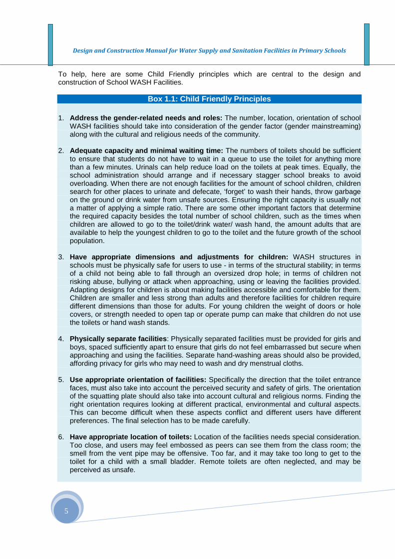
To help, here are some Child Friendly principles which are central to the design and construction of School WASH Facilities.
Box 1.1: Child Friendly Principles
1. Address the gender-related needs and roles: The number, location, orientation of school WASH facilities should take into consideration of the gender factor (gender mainstreaming) along with the cultural and religious needs of the community.
2. Adequate capacity and minimal waiting time: The numbers of toilets should be sufficient
to ensure that students do not have to wait in a queue to use the toilet for anything more than a few minutes. Urinals can help reduce load on the toilets at peak times. Equally, the school administration should arrange and if necessary stagger school breaks to avoid overloading. When there are not enough facilities for the amount of school children, children search for other places to urinate and defecate, ‘forget’ to wash their hands, throw garbage on the ground or drink water from unsafe sources. Ensuring the right capacity is usually not a matter of applying a simple ratio. There are some other important factors that determine the required capacity besides the total number of school children, such as the times when children are allowed to go to the toilet/drink water/ wash hand, the amount adults that are available to help the youngest children to go to the toilet and the future growth of the school population.
3. Have appropriate dimensions and adjustments for chi ldren: WASH structures in
schools must be physically safe for users to use - in terms of the structural stability; in terms of a child not being able to fall through an oversized drop hole; in terms of children not risking abuse, bullying or attack when approaching, using or leaving the facilities provided. Adapting designs for children is about making facilities accessible and comfortable for them. Children are smaller and less strong than adults and therefore facilities for children require different dimensions than those for adults. For young children the weight of doors or hole covers, or strength needed to open tap or operate pump can make that children do not use the toilets or hand wash stands.
4. Physically separate facilities : Physically separated facilities must be provided for girls and
boys, spaced sufficiently apart to ensure that girls do not feel embarrassed but secure when approaching and using the facilities. Separate hand-washing areas should also be provided, affording privacy for girls who may need to wash and dry menstrual cloths.
5. Use appropriate orientation of facilities: Specifically the direction that the toilet entrance
faces, must also take into account the perceived security and safety of girls. The orientation of the squatting plate should also take into account cultural and religious norms. Finding the right orientation requires looking at different practical, environmental and cultural aspects. This can become difficult when these aspects conflict and different users have different preferences. The final selection has to be made carefully.
6. Have appropriate location of toilets: Location of the facilities needs special consideration.
Too close, and users may feel embossed as peers can see them from the class room; the smell from the vent pipe may be offensive. Too far, and it may take too long to get to the toilet for a child with a small bladder. Remote toilets are often neglected, and may be perceived as unsafe.

Design and Construction Manual for Water Supply and Sanitation Facilities in Primary Schools
6
7. Appropriate designs for different age groups: The detailed design of the facilities provided must also be young child friendly. Steps must be easy to climb. Door handles must be easy to reach. The toilet interior cannot be too dark. Squatting plates must be designed to accommodate a child’s feet rather than those of an adult. Even a well-designed facility faces the risk of not being used if it has a poorly considered location.
8. The facilities should encourage hygienic behavior: Hand-washing facilities must be
provided in each toilet block, together with water and soap. The hand-washing stand must be sized to facilitate its use by smaller as well as larger children. The facility must provide an acceptable degree of privacy for girls. The design must facilitate the filling of water containers by children. Therefore, water and sanitation facilities must be simple to use, provisions for hand washing and anal cleansing should be integrated into the entire package of facilities, and water and soap should be available at all times.
9. Address the needs for children with physical disabi lities: Facilities provided must
include provision for disabled children, with at least one toilet cubicle for girls and one for boys modified accordingly. Exclusion from basic services and facilities, such as sanitation and safe water, can result in isolation, poor health, and poverty. In terms of design, ramps and hand rails should be provided, with more internal space for a caregiver to assist if necessary. Disabled girls and boys should be consulted with their able bodied peers to get the design right. When incorporated in the original design, the adaptations can be made at little additional expense. Adaptations are no separate facilities but merely imply small no-cost or low-costs design details that allow disabled to use the facilities.
10. Do not harm the environment: Improving hygienic conditions in schools may have an
impact on the overall environment. Some sanitary solutions may pose risks of soil and groundwater contamination, while others may produce wastewater flows that must be managed. WASH facilities and related practices should be designed to encourage children to understand their environment and conserve scarce resources, especially water resources. With the right technology and safe supervision, urine, waste water and composted faecal matter from toilet pits can be reused to support agricultural production and boost the school’s budget.
11. Look for low-cost solutions without compromising qu ality: There is tendency to
construct the cheapest possible school facilities in order to reach the highest coverage possible. Regrettably this also often results in low-quality facilities that require excessive maintenance and neither enable nor promote better hygiene practices among school children. Best are those facilities that are affordable, durable, encourage proper use, and are easy to maintain and keep clean. Investing in good quality, sustainable facilities therefore means investing in overall public health. Moreover, despite higher initial investment costs, money will be saved in the long run because the facilities have a longer lifespan and require less maintenance. On the other hand, this does not mean that the most expensive options are best. It is always a matter of finding the right balance between costs and quality.
12. Addresses the environmental, cultural, religious an d socioeconomic factors: Designs
for water supply, and sanitation facilities needs to accommodate the environmental; cultural and religious factors into consideration.

Design and Construction Manual for Water Supply and Sanitation Facilities in Primary Schools
7
SECTION II: Water Supply for Schools
2.1 Introduction
Water is a critically needed resource for both drinking and sanitary uses in schools, and without adequate and reliable water supply, it is difficult to sustain a healthy and learning environment for children. Each student requires about five liters per day for meeting the metabolic and sanitary and hygiene requirements, to keep the toilets and urinals clean as well as for hand-washing after using toilets and urinals. The designed school latrine and urinal cannot function without water. Water supply projects for schools must clearly address these water requirements. The provision of clean and safe water in plentiful quantities, adequate sanitary and hygienic facilities is a significant factor in the improvement of the health status of school children particularly in prevention of the diseases that prevail in most schools. Hence a school without water supply and sanitary facilities could be a potential spot for the spread of diseases. A survey made by the Ministry of Health in collaboration with UNICEF in 2007 showed that about half of the ailment found among school children is related to urinary infections and it is by lack of personal hygiene caused by inadequate provision of water. In the absence of water supply, sanitation and hygiene services in schools, water born disease can easily breakout and rapidly transmitted by any route which permits faecal material to pass into the mouth, and there is a vital linkage and intimate relationship between health and personal hygiene, which depend largely on the availability of sufficient water and sanitary facilities. It is for this reason that access to adequate and safe water supply for sanitation services is basic in schools. The services are needed to promote the use of sanitary facilities and hand washing practices as an important life skill for school children. This section of the manual is devoted to the physical activity required that enables schools to have access to improved water supply services. It will focus on giving technical details, particularly on the hardware part of the water supply systems for schools in Ethiopia. 2.2 Major Water Supply Systems Broadly there are two water supply systems that can effectively be used in schools in Ethiopia, and these are: (i) Rainwater catchment system, (ii) Groundwater supply system,
� Spring catchment � Hand-dug well � Bored or drilled well (shallow and deep wells)
Apart from the above two major water sources, there are convention water supply sources where water may be taken directly from a river or lake or reservoir and subjects it to treatment before domestic use. The water treatment requires higher investment and high level management that demands the use of a complex set of equipments, and these water supply systems has limited application for use in schools. Hence a design and construction details on these systems is beyond the scope of this manual. If there is exceptional need that require the development of small scale water treatment systems, references are available in several books and web sites.
Design and Construction Manual for Water Supply and Sanitation Facilities in Primary Schools
1
In this manual, roof water harvesting is discussed as the most widely used and technically and environmentally feasible option for school water supply in Ethiopia primarily as a supplementary to other source that may be considered. The design and construction may need mixing and adapting different technology options to meet the desired water demand for schools with different population sizes. Specific design, construction and management requirements may have to be developed. Practicing engineers, hydrologists, hydro-geologists and contractors may have to adapt the proposed technologies to their own local situations and needs. 2.2.1 School Rooftop Water Harvesting Almost all water that we use every day is from rain and it is part of the hydrologic cycle. The water bodies in rivers, lakes, reservoirs, ponds, in the soil and all underground waters have their origin from rainwater that finds its ways to each type of water bodies through different hydrological processes, so that these water bodies can be utilized when the rain is not actually falling. The average annual rainfall in Ethiopia is 800 mm, and for most part of the country, 80% of this rainfall occurs over a three months main rainy season – June to August, and nearly 20% occurs in March and April (short rainy season). Most schools open in September and high water demand exist there after throughout the dry periods – October to May with the driest period in February to May. Roof-water harvesting has high potential in areas that receive higher rainfall and have longer rainy season, and these areas include south western, central and eastern highlands of Oromia, southern western Amhara, most of SNNP regions. Such areas can meet their water needs through harvesting rainwater in higher possible size storage facilities. Rainwater harvesting can be an important supplementary resource to meet water demand in central and eastern highlands of Oromia, north and eastern Amhara and most of Tigrai. Roof-top water harvesting is the simplest, less expensive and obvious choice for many of the schools in the country, where there are several and large roof structures made of corrugated galvanized iron sheets. The harvested water is always useful for many purposes and hence roof water harvesting is an important and attractive investment choice for two reasons;
(i) In areas where groundwater development is either difficult or has been rendered unusable by high level fluoride content, salinity, etc., and
(ii) In areas where the only available option is surface water. Roof water harvesting systems involve six essential components:
� Catchment surface: the collection surface from which rainfall runs off, � Gutters and downspouts: channel water from the roof to the tank, � Leaf screens, first-flush diverters, and roof washers: components which remove debris
and dust from the captured rainwater before it goes to the tank, � Storage tank: one or more storage facilities, plastic (ROTO) or reinforced concrete/
masonry water storage facilities called cisterns (placed either underground or surface) are needed,
� Delivery system: on spot at the storage or gravity-fed or pumped to the end use, � Treatment/purification: this is done to make the water potable; chlorination or use of
filters and other methods to make the water safe to drink.
Of the above components, three are major ones in the design and construction of roof-top water harvesting system.

Design and Construction Manual for Water Supply and Sanitation Facilities in Primary Schools
2
Catchment Areas: Catchment areas are hard impermeable surfaces (roof) on to which rain falls. Schools have sufficient roof catchments that are made of galvanized corrugated iron sheets from which water could be harvested and used as long as there is rain falling. Gutters and down pipes: These are conveyance channels for the harvested water from the roof to the storage container. In Ethiopia gutters are constructed from galvanized iron sheet folded to the required dimensions, and most often they are rectangular or trapezoidal in shape. Down pipes can be made from PVC or galvanized iron sheet, and there is enough local skills in the country to produce these accessories. Gutters and down pipes should have filters to remove solid materials along with the water flowing through. Storage : The storage tank is the most expensive component of the rainwater harvesting system. The availability of readymade plastic storage facilities made rooftop water harvesting less time taking, attractive and an important water supply option for schools in Ethiopia. Unless cost restricts, as much as possible the storage needs to be large enough to capture all the harvested rainwater particularly in areas where other sources of water supply systems are technically or environmentally less feasible. The shape of the storage can be cylindrical, spherical, rectangular or square, and they can be constructed from ferro-cement (RC), masonry, readymade plastic containers (ROTO), etc. How much water can we get from school roof top in a year? The rainwater that can be harvested from the roof top depends on the rainfall intensity (inches /cm2/hr) in the catchment area/site, and the characteristics of the roof area and available storage facility. The volume of water that can be harvested in a given time period is estimated using an empirical equation presented below (equation 1). The water that runs off a roof (Q) in liters per year is fairly easy to calculate using the following formula. Q = CRA ……………………………………………………………………… Equation (1)
Where:
C = Runoff coefficient and it takes account of the losses due to evaporation from the roof area, losses in the gutters and down pipes, and it is taken as 0.8,
R = Annual rainfall in milliliters (converted in meters), if the year is taken as the design time frame,
A = guttered roof area in square meters (m2),
Water Quality Rainwater is naturally high quality water. It should be recognized however that rainwater collected from roof in most schools is considered less safe for drinking for two major reasons (i) a roof can be a natural collection surface for dust, leaves, blooms, twigs, insect bodies, bird feces, and airborne residues such as pesticides and insecticides in areas where there exits commercial farms, and (ii) the harvested water is stays long before freshwater refills the storage tank. 2.2.2 Groundwater Sources About 70% of the water supply source in Ethiopia is from ground water source such as spring and wells. Springs, dug wells, and bored or drilled shallow and deep wells are ground water

Design and Construction Manual for Water Supply and Sanitation Facilities in Primary Schools
3
sources that are available as potential water supply sources for schools in Ethiopia. These sources are more important since groundwater does not require special treatment for water quality and it is generally safe to drink directly from the source because of natural filtering through the soil and hence it is less expensive for use in schools and in communities. Deep machine drilled wells are not discussed in this manual because of the following reasons: (i) its high initial capital investment and operation and maintenance cost, and (ii) the yield (quantity of water) produced is very large and beyond the demands of most primary schools, (iii) most often its sitting may be falling outside of the premise of the school and creates ownership and management problems, and (iv) it may involve more advanced technologies (motorized pumps, large storage facilities and strong management to optimize the resource). Owing to the highly varied topography, climate and geomorphology of the country, there are wide range of groundwater sources that can be developed and used and the major ground water supply sources that are considered appropriate, financially realistic and useful for school water supply include the following. 2.2.2.1 Spring water Springs are ground water resources that occur where the natural flow forces the groundwater to appear at the surface on a sloppy ground or at valley bottoms. Springs in Ethiopia are located in large number in high rainfall areas, along the slopes and valley bottoms of mountainous areas and escarpment or edges of plateaus that have adequate rainfall input and vegetative land cover. Springs are hardly found in dry lowland areas. The spring water is obtained from a water bearing formation called aquifer. Spring water is usually fed from ground water formations – aquifers or water flowing through fissured rock. The catchment area has to be conserved and protected for a sustainable water supply and reliable yield. Spring water is generally safe water and inexpensive in its development. The main structural components of the spring water system include:
(i) A protective structure at the source or where it appears at the ground surface (eye of the spring),
(ii) A collection chamber (storage) which is used for collecting night storage and it is located downstream of the protective structure,
If the catchment of the spring is conserved and protected, springs are reliable water sources that can supply water in adequate quantity and quality. The collection point needs to be protected properly and the necessary natural hydraulic conditions (free flow) should be maintained for its optimal use. This involves a survey in order to ensure there is adequate water flowing from the eye of the spring, the area it covers and its potential for a free flow, the presence of a sufficient head for the water to flow to the collection chamber. Design and construction plan has to be prepared to protect the spring water at the site where it initially appears (eye protection). The water flowing from the eye protection chamber should be conveyed to (i) on spot use, (ii) a collection or storage facility; and it required an appropriate site downstream where collection chamber could be installed and from which the water can be piped under gravity. If the drinking water point in the school is at an elvated site from the collection chamber, pumps could be used to deliver the stored water to a storage facility on an elevated ground so that water can be distributed to the drinking fountains, latrines and hand washing
Design and Construction Manual for Water Supply and Sanitation Facilities in Primary Schools
4
facilities in schools. The problem with spring water is that its sources are rarely located within the premise of a school, and in such cases it is owned and managed by the community. If there are proper agreements and memorandum is signed with the community, schools can have access from these sources through pipeline connection. 2.2.2.2 Wells A well is a hydraulic structure, which when properly designed and constructed, permits the economic withdrawal of water from underground water–bearing formation or aquifer. Wells (both shallow and deep) are vertical shafts that are dug or bored or drilled into the ground for the purpose of accessing and supplying safe and reliable water from underground aquifers. There are different well types and these are (i) hand-dug wells, and (ii) bored or drilled wells. Hand Dug wells and Bored or Drilled Wells are further classified as shallow and deep wells based on the extent of their depths to water level in the ground. Wells with depths less than 45 meters are shallow wells. (i) Hand - dug well – The Basics As the name implies, hand-dug wells are excavated wells, and the excavation (digging) is done by hand and their diameter is larger than 1 meter. Hand dug wells for schools are lined or use concrete tubes (Caisson sinking). In this manual we are discussing protected hand dug wells where the surface area is covered and the upper part of the well shaft above the water level is water tight sealed and protected from any runoff or dirt entering the well. Hand dug wells can be constructed with in the premise of the schools, and it can provide a cheaper water supply services. The existence of shallow water bearing geological formations – aquifers within in less than 30 meters depth suit to the hand dug well technology. Perched water tables are less reliable water sources and it should be avoided. The construction of hand-dug wells is done manually using skilled local artisans. Their depth ranges between 8 and 15 meters as typical and between 6 and 25 meters as effective limits (Stephon, 2006). (ii) Bored or Drilled wells The term borehole or tube well is often used for bored or drilled wells. The range of depths to the water level1/ determines whether the borehole is shallow or deep. Boreholes are drilled using hydraulic tools consisting of a series of drill-bits or augers for various applications and including the use of a set of rods which are fitted to the bits and extended as the bit descends into the ground. Drilling machine mounted on vehicles is used to construct boreholes. The machine is slowly driven into the ground, and pulled out at frequent intervals to remove the soil log which collects in it. Special fittings are available to pass through small rocks, to remove loose soil and to bail out waterlogged material from below the water table. With a well of this type, it will probably be necessary to insert casing while drilling is in progress. The casings are blind in depths above the water level and the remaining casings are perforated principally in the hole below the water table. The drilling work is completed by inserting well graded gravel pack surrounding the perforated casing to prevent the hole from caving in to the hole and also to enhance the flow of the water into the well through the perforated casing. Shallow wells are widely used as a source of water supply for schools in Ethiopia.
1 Bored wells are used usually for shallow wells because of the larger diameter boring made,

Design and Construction Manual for Water Supply and Sanitation Facilities in Primary Schools
Table 2.1 Different water supply technology options available for schools
Water Supply Technology
Options
Soil Type
Depth Main Advantages Main Disadvantages
Rooftop Water Harvesting
NA NA � With a proper design, construction and management, water is clean,
� Cost for O&M is very low, � Can benefit from large roof area from several
schools buildings to serve as a potential and reliable water supply source for a areas with long rainy season
� Capital costs may be high, � Difficult to manage demand by this
source alone, � Roofing material may be deteriorating
with time, and it may have to be replaced for safe water supply
� Water is less safe unless monitored Protected Spring NA NA � Can be used with a gravity based distribution
system once the spring source is found at higher elevation of the school, otherwise require pumping.
� Water is usually clean � Maintenance costs are low
� Spring can “escape” � Difficult to expand the system with
increased demand,
Hand – dug wells All except solid rock
Up to 20 m
� Simple Technology � Low construction and maintenance costs � It can be closed, protected and safe,
� Excavation can be dangerous � Water level can fluctuate and may dry
soon unless sufficient depth is developed during the construction
Driven Tube Well (Augured well)
Soft Up to 15 m
� Fast drilling time � Well point is reusable � Cheap, simple technology
� Well point is small � Difficult in rocky soil � May need casing
Bored shallow well
Soft Up to 45 m
� Fast drilling time � Cheap, simple technology
� Bore wells have large diameter and give large surface area for water to enter into the well
� Difficult in rocky soil � May need casing
Drilled Shallow Well
Soft Up to 60m depth
� Fast drilling time � Can strike a reliable water source formation
� Equipment can be expensive � Requires a plentiful supply of water � Require casing
NA – Not applicable

Design and Construction Manual for Sanitation Facilities in Primary Schools
2
SECTION III: DESIGN AND CONSTRUCTION OF WATER SUPPLY FACILITIES
3.1 Introduction In many aspects, the water supply systems for schools are not different from community water supply systems. Relatively fewer water supply systems are technically, environmentally and financially feasible and meet the specific needs of schools. However, the different local and environmental situations within which schools exist which include the topography, climate, geomorphology, geology, etc. limit the choice of the technology options. Many schools are fully integrated with the local community. This may be an advantage in many respects, for example, the possible site for water points may fall in community property rather than in the premises of the school. As a result the feasible water supply system may require the design and construction of hand dug wells or boreholes due to the topography of the site where the school is located. More importantly it may be possible for the school to share water from a community water supply. If the water supply system for the community is deep well with motorized pump with sufficient water, schools can have access through supply pipelines. According to many of the regional water bureaus, they consider this option as a priority and most feasible option on their list of priorities set for school water supply development. 3.2 Water Demand Estimated water demand per day for a school with average school population at peak hour water demand is given in box 2 below.
Box 3.1: Water Demand in Schools
The fundamental question: How much water is needed? For a typical rural school of a given population, with a VIP type toilet, urinals, we estimate that 1 litre is needed for drinking, 0.5 litres for hygiene (hand washing with soap) and 0.5 litres for cleaning both the toilet and urinal per student per day. There are also needs for water for cleaning class rooms, offices, and for greening schools. For a 4 stand toilet block and urinal (catering for 400 students), this equates to 200 litres for hand washing and 200 litres for cleaning. Inevitably, some water is wasted, and additional water may be needed for menstrual hygiene, so an average of 2 litres per student per day ONLY FOR HYGIENE AND TOILET CLEANING is appropriate. An additional 1 to 2 litres per student per day is needed for DRINKING. Even providing a total of 3 to 4 litres per student and teacher can be a great challenge for some schools. An additional one to two meters cube of water is required for other uses in schools including irrigating green areas. Much more water is required for residential schools, for staff living on campus, and to operate flush toilets. The greater the water demand, the greater the amount of waste water and grey water that will need to be disposed of.

Design and Construction Manual for Sanitation Facilities in Primary Schools
3
3.3 Water Supply Systems The water demands shown in box 3.1 can be met with appropriate selection of water sources and provision of adequate storage facilities. After reviewing a number of basic options, a number of technology options can be considered. These are (i) springs, (ii) hand-dug wells, (iii) shallow wells, (iv) Roof-Water Harvesting, and (v) piped water supply systems from a nearby community water supply source. 3.3.1 Roof water Harvesting 3.3.1.1 Estimating roof runoff Estimating roof runoff is the first is the first in the design of the roof water harvesting for schools. The relationship shown in Box 3.2 is used for estimating the harvestable water from school roof tops. 3.3.1.2 Sizing storage facilities Water demand for a school having three blocks of buildings (20m by 4m) with about 600 students needs about 3,000 liters every day for drinking, hand washing and cleaning latrine and urinals (see box 3.1 and 3.2). A reservoir designed to hold 60 school days supply (around three calendar months) would need to have a volume of 180,000 liters.
Box 3.2 A case of a sample school
In one of the schools, you have two equal blocks of school building with a dimension of 20 meters by 4 meters. Suppose there is a rainfall of 950 mm a year, the design equation gives the following roof top runoff (Q) from the school buildings: Q = 0.8 R A ……………………………………………… from equation (1) above Where: R= is the rainfall in millimeters A= is the guttered roof area of the building block in square meters, 0.8 = is a “runoff coefficient, C” which takes into account loses between the
roof and the storage facility Based on the above relationship, the expected water harvested from the rooftop is 63.0 m3 from each school building. The school can have a total of 126 m3 or 126,000 liters of water in a year from both buildings. Using the rule of thumb of one-fourth of the yearly total as the design value for storage facility, approximately 10m3 or 10,000 liters of storage facility can be selected and used in each side of the school buildings, and it is adequate to capture sufficient runoff water for the school. If the harvested water is properly managed and used for drinking, cleaning toilets and hand washing, a school of 600, 800, 1000 and 1500 student population will use the water for approximately 5, 4, 3, and 2 months (of 20 school days per month), respectively, and this is quite a valuable resource a school cannot let it waste.
Design and Construction Manual for Sanitation Facilities in Primary Schools
4
The most common design (rule of thumb) for sizing storage facilities is to take a quarter of the estimated demand, and still this is a relatively expensive proposition. Accordingly two 5,000 liter storage tanks placed at each side of the school buildings (totaling 10,000 liters for each building) needs to be designed to take full advantage of the harvested roof water, i.e. placing two 5000 liter storage tanks in each side of the building may be a better option than one 10,000 litter although still expensive. If one tank or its roof catchment needs repair, first the other tank on the other side of the building block can still provide some water, and secondly such design would allow shorter slope length for the gutter reducing overflow and spillage. A ferro-cement and masonry storage facilities may be the most cost effective water storage tank material where possible, but this depends on the local availability and cost of construction materials and skilled labour. The roof catchment and gutters need frequent maintenance, and the system should be fitted with a first flush system to reduce the risk of debris- and contamination – entering the tank. 3.3.1.3 Standard Specifications Selecting Gutters – It is important to select material, designing the shape and slope for a gutter so that the harvest water is directed to a storage facility and prevent the water from running down and damage or stain the roof walls. Most gutters in Ethiopia are constructed from galvanized iron sheet of size 04 mm or 28 Gage galvanized iron sheet. The shape is trapezoidal where the bottom width is 10 cm, depth 10 cm and an internal width of 15 cm. Leaf and debris screen: To remove debris that gathers on the catchment surface, and ensure high quality water, a ¼-inch mesh screens in wire frames should fit at the down pipe close to the storage tank. Storage Facility: Two types of materials can be used as storage facility for roof top water harvesting and the first is Plastic Water storage facility (ROTO) with a water holding capacity of 2, 3, 5 and 10 m3, and the second one is masonry storage facility widely used for community water supply in rural areas. A plat form need to be constructed for resting the storage facility at a suitable location next to the building, and a masonry foundation of 45 cm depth below ground and about 50 cm structure above
2/ For an average school population of 700 to 800
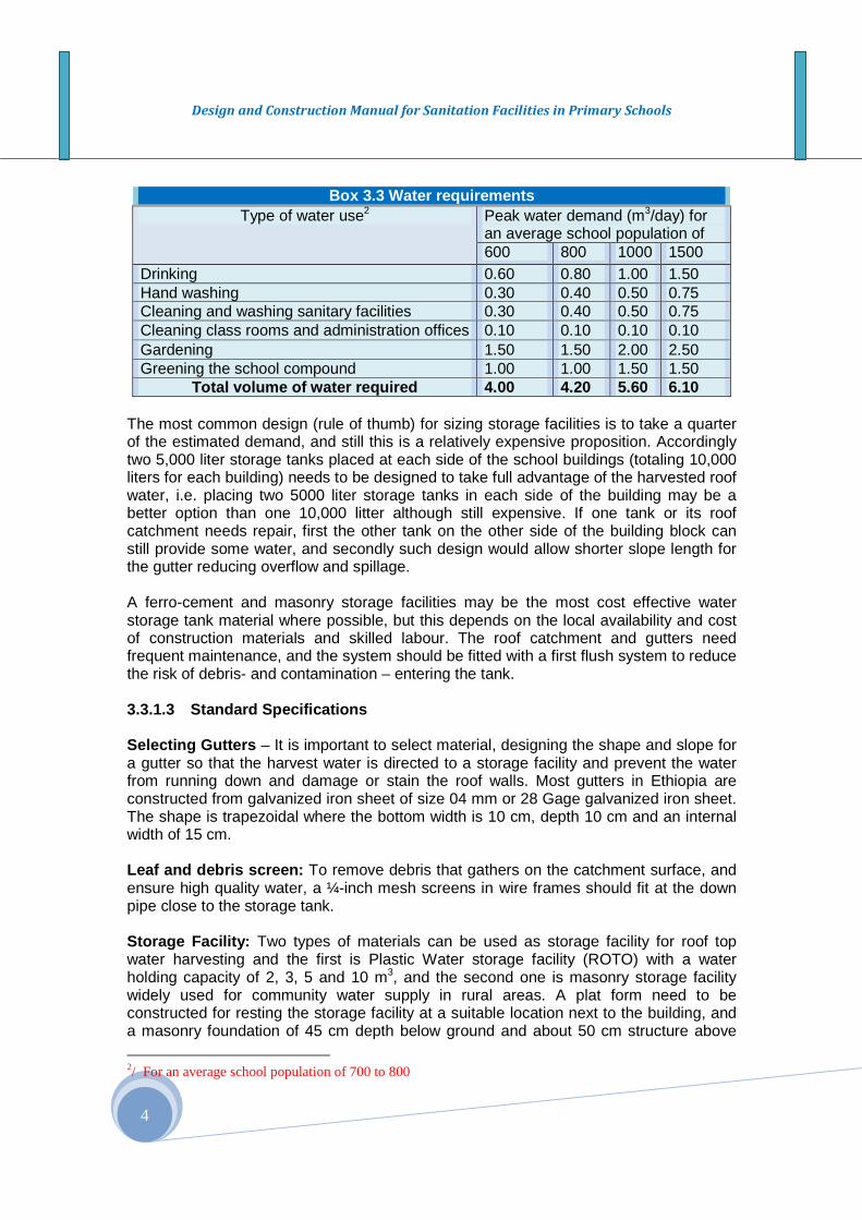
Box 3.3 Water requirements Type of water use2 Peak water demand (m3/day) for
an average school population of 600 800 1000 1500
Drinking 0.60 0.80 1.00 1.50 Hand washing 0.30 0.40 0.50 0.75 Cleaning and washing sanitary facilities 0.30 0.40 0.50 0.75 Cleaning class rooms and administration offices 0.10 0.10 0.10 0.10 Gardening 1.50 1.50 2.00 2.50 Greening the school compound 1.00 1.00 1.50 1.50
Total volume of water required 4.00 4.20 5.60 6.10
Design and Construction Manual for Sanitation Facilities in Primary Schools
5
the ground is desirable so that access and drawing water from the tap of the storage facility using taps and Jeri cans is possible. If the width of the school building under consideration is long enough say more than 30 meters, this manual recommends the use of two storage facilities (5 m3 each) placed in each side of the school buildings in order to reduce the drop in the elevation of the gutter as it reaches the storage. Knowledge of the local situation and based on rainfall intensity, size of gutters have to be designed neither too small nor too large and should be able to capture at least 95% of the roof runoff.
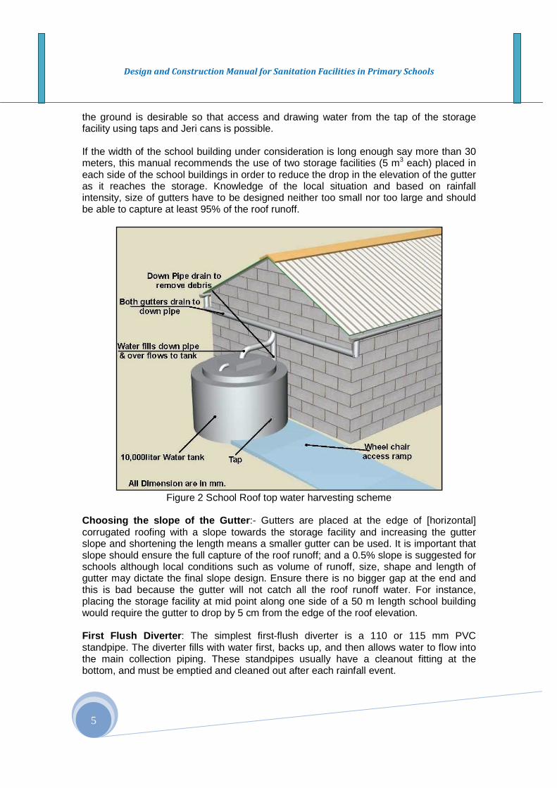
Figure 2 School Roof top water harvesting scheme
Choosing the slope of the Gutter :- Gutters are placed at the edge of [horizontal] corrugated roofing with a slope towards the storage facility and increasing the gutter slope and shortening the length means a smaller gutter can be used. It is important that slope should ensure the full capture of the roof runoff; and a 0.5% slope is suggested for schools although local conditions such as volume of runoff, size, shape and length of gutter may dictate the final slope design. Ensure there is no bigger gap at the end and this is bad because the gutter will not catch all the roof runoff water. For instance, placing the storage facility at mid point along one side of a 50 m length school building would require the gutter to drop by 5 cm from the edge of the roof elevation. First Flush Diverter : The simplest first-flush diverter is a 110 or 115 mm PVC standpipe. The diverter fills with water first, backs up, and then allows water to flow into the main collection piping. These standpipes usually have a cleanout fitting at the bottom, and must be emptied and cleaned out after each rainfall event.

Design and Construction Manual for Sanitation Facilities in Primary Schools
6
3.3.2 Spring Protection 3.3.2.1 Introduction The essential nature of a spring is that ground water is flowing along the top of the aquifer layer by gravity until it reaches an outlet at the surface. The spring water appearing on the surface is allowed to flow freely and it has to be “captured” fully in order to be stored and used. This situation hardly occurs inside school premises. Springs are often perennial in nature and there are users of the excess water downstream. In order to protect, develop and use the water of such springs for school, the school administration has to hold consultation with the downstream community users in the area, and provide the necessary provisions accordingly. 3.3.2.2 Design and construction The spring protection work has three major infrastructural works which are the following:
(i) Spring box (ii) Collection chamber/reservoir (iii) Tap stands
(i) Spring Box: Site selection:
� Eye of the spring are located based on the geology and geomorphology of the area,
� It should be at least 30 meters upstream from a potential source of pollution or contamination.
Development and Protection of the eye of the spring :
� The spring collection area is the heart of a water supply system, and care and experience is needed for proper spring construction.
� Excavation work should sufficiently expose the eye of the spring, and the width of the free seepage lines that determines the width of the wing wall,
� Hence the free flow or seepage water (spring) at the eye of the spring has to be first captured, collected and directed to the spring box (see figure 3.3 and 3.4),
� Appropriate drainage ditches should be constructed to divert any surface runoff from entering to the eye of the spring from upland areas,
� An experienced artisan (masonry worker) should be used in the construction of the eye of the spring, and it requires at most care.
� The spring box has wing walls that intercepts, direct and collect the flows to the spring box,
� The spring box has ventilation at the top, and the top side bends downward as shown in figure, and it should have sufficient height so that children will not have access to the inlet. At the downstream side, the box has an over flow pipe (centered at the same elevation as the piezometric surface of water in the aquifer formation so that there is no back flow) and a drain pipe at the bottom of the box (see plan view of a spring in figure 3 and 4 below),

Design and Construction Manual for Sanitation Facilities in Primary Schools
7
� The eye of the spring should be fenced and protected, � The catchment area upstream of the eye of the spring should be conserved and
protected for a sustainable water yield,
Generally spring water is of good quality water and contamination is less if the eye of the spring is properly located and constructed. The soil must be thick enough to provide natural filtration and biological action for natural filtration. Therefore schools and their communities need to recognize the significance of the need for the rehabilitation and maintenance of the catchment of the spring through soil conservation and afforestation, which schools with the communities should plan and organize a catchment protection and management work. (ii) Collection Chamber/Reservoir Construction of the collection chamber should take into consideration that it acts as a sedimentation tank as well. Thus, access must be provided for regular cleaning. Figure 8.11 illustrates a detailed view of a spring collection area design. The major parts of the construction are the permeable construction and the barrage (dam). The permeable construction is a package of filter material made of rocks, stones and gravel that allows water to drain into the supply pipes. Perforated pipes surrounded by a gravel filter package are sometimes used instead of dry stone masonry but the latter is preferable. The barrage can be a concrete dam or a stone masonry construction controlling the drain and directing water into the supply pipes. It also carries the load of the backfilling. The floor of the permeable construction and the perforated pipes slopes at about 2%.
If the collection chamber lay in a low spot area relative to the location of the school, a small capacity solar or wind power pumping systems3 could be used to lift the water from
3 Environmentally friendly pumping systems that do not have emission of environmental significance
Source: MWRI, 2009. A manual for field staff and practitioners. Produced by the Government of Sudan in partnership with UNICEF. April 2009.
Figure 3.3 Schematic section of a spring eye development with a spring box
Design and Construction Manual for Sanitation Facilities in Primary Schools
8
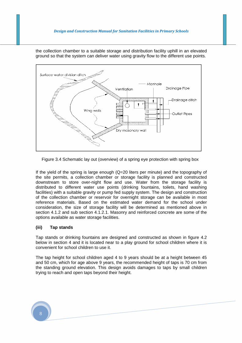
the collection chamber to a suitable storage and distribution facility uphill in an elevated ground so that the system can deliver water using gravity flow to the different use points.
If the yield of the spring is large enough (Q=20 liters per minute) and the topography of the site permits, a collection chamber or storage facility is planned and constructed downstream to store over-night flow and use. Water from the storage facility is distributed to different water use points (drinking fountains, toilets, hand washing facilities) with a suitable gravity or pump fed supply system. The design and construction of the collection chamber or reservoir for overnight storage can be available in most reference materials. Based on the estimated water demand for the school under consideration, the size of storage facility will be determined as mentioned above in section 4.1.2 and sub section 4.1.2.1. Masonry and reinforced concrete are some of the options available as water storage facilities. (iii) Tap stands Tap stands or drinking fountains are designed and constructed as shown in figure 4.2 below in section 4 and it is located near to a play ground for school children where it is convenient for school children to use it. The tap height for school children aged 4 to 9 years should be at a height between 45 and 50 cm, which for age above 9 years, the recommended height of taps is 70 cm from the standing ground elevation. This design avoids damages to taps by small children trying to reach and open taps beyond their height.
Figure 3.4 Schematic lay out (overview) of a spring eye protection with spring box
Design and Construction Manual for Sanitation Facilities in Primary Schools
9
3.3.3 WELLS A well is a hydraulic structure which, when properly designed and constructed, permits the economic withdrawal of water from a water bearing formation – Aquifer. How adequate is a well for the purpose depends on three things (Johnson Division, 1975):
(i) Appropriate application of the principles of hydraulics in the analysis of wells and aquifer performances,
(ii) Skills in digging, drilling, and well construction insures taking best advantage of the geologic conditions, and
(iii) Selection of construction materials that insures long life. Both the person in charge of the design of wells and the one who constructs them need to know the fundamentals of well hydraulics. In the absence of skilled personnel, this could be the major causes for the failure of many of the dug well and mostly the machine drilled wells in many parts of the country. 3.3.3.1 Hand-Dug Well – Design and Construction In Ethiopia there are well experienced local artisans for constructing hand dug wells. Local artisans construct the well shaft maintaining straight alignment and standard dimensions. Properly designed and constructed hand – dug wells provide a viable alternative to many of the unhygienic and unprotected water sources that are being used by a large part of the country. It is less expensive and also avoids high capital and maintenance costs compared to machine drilled wells.
To make the construction of a hand-dug well viable, water must be available in sufficient quantities at shallow depths (6 to 25 m) that will allow safe excavation and economically feasible exploitation of the water resource in the well. This will depend, of course, on a range of specific local conditions, for instance it must have stable soil and a depth to the water table that does not allow pollution. (i) Site selection The site selection should be done by a team which needs to include the school administration and a suitably qualified water engineer or hydrogeologist. The site should be within the premises of the school compound. Detailed site selection information is covered elsewhere (MoWE, 2006). (ii) Construction The construction of a standard hand-dug well has three main elements: (ii) the Head Work, (ii) the Well Shaft, and (iii) the Well Bottom. A typical hand-dug wells design is shown in figure Annex A1. The main features of each of the elements are given below. Well Shaft
� Hand Dug Wells for schools are required to be lined so that it can provide long years of
service. Lining could be done with bricks or stone or use of prefabricated reinforced concrete tubes. This manual recommends the use of Caisson sinking for proper

Design and Construction Manual for Sanitation Facilities in Primary Schools
10
digging of the well and safety during construction. It is an effective method of digging and deepening hand dug wells in both stable and unstable formations, provides long duration of service (Stephon, 2005). The procedure is similar to what is seen in figure 3.5. For further information, contractors are advised to refer Stephon Bolt, 2005 on steps to follow on caisson sinking method and equipments required for digging hand dug wells.
� A minimum thickness of 75 mm for precast concrete is suggested,
� The diameter could range between 1.3 to 1.5 meters but this could depend on the mold available for local manufacturing of the RCBs,
� At least the top 3 meters depth is sealed to prevent surface water from entering the well,
� The void between the well lining and the surrounding ground should be packed with graded aggregates for those with precast concrete rings. Ensure the well is deep enough (more than three meters to provide water through the dry season,
� The well below the water table or often called intake section of the well should be deepened enough (up to six meters) below the water table to ensure a continuous and dependable water supply in all seasons,
� Caissons all the way along the well shaft : Caisson sinking provides a safe working environment, a superior and very cost effective method of lining hand dug wells, and simpler and require less costly equipment purchase. For more information, please refer for more details on Caisson Sinking methods.
� The concrete casings above the phreatic line or water table are blind and the concrete casings are perforated in well below the level of the water table,
� Use perforated concrete rings below the water table to allow water to enter to the intake area of the well. The digging/excavation work below the water table requires additional equipment – a dewatering pump. The water in the well is regularly dewatered to allow further excavation to reach a minimum depth of three meters and a maximum of six or more meters. After the perforated concrete rings are put in place, a well graded gravel envelop surrounding the perforated concrete rings is packed to prevent clogging the perforations by the soils and also to improve the hydraulic conductivity from the aquifer to the well,
Well Bottom The well bottom is the water bearing formation of the well. Water enters both along (horizontally from the wall of the well and also vertically upward from the lower side of well bottom), and it should be designed and constructed considering such hydraulic features. Well bottom should have the following:
� It should penetrate the aquifer adequately by at least three to six meters:
Figure 3.5 Well digging (Water Aid/ Picture by Caroline Penn )
Design and Construction Manual for Sanitation Facilities in Primary Schools
11
� Three meters for minimum yield4/ of 10 liters per minute � Two and half meters for 15 liters per minute � Two meters and a minimum yield of 20 liters per minute � Place layer of gravel in the bottom of the well to facilitate flow from below and
to avoid silting up. Construction Safety:- Artisans should have the necessary protective equipments. During the construction period, a protection wall of at least 70cm high wall must be built to prevent school children falling in until the well is fully completed with cover slab and a hand pump installed. Skilled and knowledgeable contractors have to be contracted to ensure the successful completion of the well and safety of workers during the construction process. Head Works:- Head Works include the protective apron, channel for drainage water and the soak-away pit. It stands out above the surrounding ground, and it requires proper design and construction for stability of the soil and rock at the site, to support the hand pump and avoid potential seepage into the well from excess water from the pump (drainage water) and surface runoff from the surrounding areas. Proper care should be taken in mixing the concrete and reinforcements and allow them to cast properly. Recently a new design of the head works for hand dug wells has been considered as suitable for schools. The head work is designed on an elevated platform of about 1.5 m to 2.0 m masonry structure above the ground surface so that the pump outlet is connected to a ROTO storage facility so that a drinking fountain can be designed at lower elevation to allow gravity supply. In general the head work for hand dug wells should have the following: � A minimum of at least 3 m diameter protective apron which has a 25 cm of height; a
height from the surrounding ground surface. A foundation masonry structure of 45 to 60 cm is constructed after the land and debris are cleared and a superstructure of the hand-dug well rests on it,
� Should have a cover slab which seals and protects the well shaft, but with an access hole and removable hatch and a 150 mm diameter hole for installing a hand pump rising main (see figure Annex A1),
� Having selected the most appropriate hand-dug well design, the construction work will have to be organized. Whichever option is chosen, the involvement of the school community in any decision making including school children is important.
� The excess or drainage water is directed to a soak-away pit or underground cistern. (vii) Detail specifications Inside diameters of the well shaft:- the standard diameter ranges between 1200mm to 1500mm. The inside diameter for water intake area could be lesser or equal to the diameter of the well shaft above it.
4 hydraulic conductivity of the soil/geologic formation

Design and Construction Manual for Sanitation Facilities in Primary Schools
12
Depth of the water column:- The depth of water column in the water intake area must be in the range between three and six meter depth or more to make the well productive. The well yield should meet dry period water demand and must secure a minimum of three meters of water column during the dry period between March and May. Well cover (apron): The well cover will have a diameter of 3 m apron and a thickness of 150 mm and should have reinforcement bar of 12 mm Ø circular edge bar. A 40x40 cm plate with a circular opening (150 mm Ø) at the center of the plate that has a bolt at each corner is constructed and put in place for installing the hand pump. A 60 x 60 cm access hole is also constructed with a RC cover slab located at one convenient side of the apron as shown in figure Annex A1. Soak Away : The excess water is channeled to a soak away facility and detail on the design and specification of the well cover is shown in figure Annex A1. The soak-away should be located at a distance of at least 20 meters away from the well. For those schools with additional fund, the soak-away could be replaced with an underground cistern to store and use the excess water for gardening and for greening the school compound. (viii) Equipments and materials: The major equipments and tools required for the excavation and digging of hand-dug wells include Tripod with one tone Chain Block for Caisson sinking, excavation tools, dewatering pump, etc. For more details on the list, refer manual developed by the MoWE (2006). 3.3.3.2 Drilled Wells The quantity of water made available by a well will depend on rainfall, geomorphology and hydrogeology, soils of the site under consideration. It will also be influenced by the diameter of the hole made to extract the water and by the depth of penetration into the water-bearing stratum - aquifer. The specification of the well and it accessories for optimal yield is desirable, and below discusses this aspect of the design work. (i) Well diameter – the choice of the well diameter has to be made during the design stage, since it affects significantly the cost of the well construction. The well diameter must be chosen to satisfy two important requirements:
� The well casing must be large enough to accommodate the pump diameter which is related to the total dynamic head required to pump the desired quantity of water and it must ensure and have proper clearance and efficient operation,
� The diameter of the intake section (lower part) of the well must be such that it will assure good hydraulic efficiency
Well Depth – The expected depth of the well during the construction is usually determined from the log of test hole, from logs of other nearby wells in the same aquifer, or during drilling of the production well. Generally the well is completed to the bottom of the aquifer. This is desirable for two reasons:
(i) more of the aquifer thickness can be utilized as the intake portion of the well, resulting in higher specific capacity, and
Design and Construction Manual for Sanitation Facilities in Primary Schools
13
(ii) More draw dawn can be made available permitting greater well yield. The lack of ensuring the above factors are major reasons for the malfunctioning of most drilled wells in rural Ethiopia. Well Screen Length – The optimal length of well screen is chosen with relation to the thickness of the aquifer, available drawdown and stratification of the aquifer. For this manual, screening the entire aquifer for shallow wells is suggested: Well Specifications Casings: Casings shall be of steel, iron, plastic, or fiberglass of sufficient strength and durability consistent with the intended use of the water and the maximum anticipated differential head between the inside and outside of the casing. Steel and plastic casing materials shall meet the strength requirements stated in most standard specifications set International Standard Organizations (ISO). The most widely used casings in Ethiopia is plastic casings made of Polyvinyl Chloride (PVC) for depths less than 150m, and the diameters vary depending on the size of the submersible pump designed for the well. For UPV casings, a pipe diameter 5� �� inches are often used as standard diameter for medium depths to deeper wells of 100 to 150 meters depths. The smallest size, five inches inside diameter (ID) is used for shallow machine drilled well that are most often used for schools in Ethiopia.
Table 3.3 Specifications for well screen and pump size for machine drilled wells Anticipated well yield in liters per
second
Nominal size of Pump Bowel in
inches
Optimum size of well casing
Smallest size of well casing in inches
Less than 6 4 6 ID 5 ID 5-11 5 8 ID 6 ID 9-25 6 10ID 8 ID
Source: Johnson Division, UOP Inc.1980 Joints : Well casing joints shall have adequate strength to carry the load due to the casing length and still be watertight, or shall be mechanically supported during installation to maintain joint integrity. Such mechanically supported casings shall terminate on firm material that can adequately support the casing weight. Screen : Well screens for deep wells shall be constructed of commercially manufactured screen sections, well points, or field-perforated sections. Perforation by any method is allowable provided proper slot size and entrance velocity limits can be met. The length and open area of the screen shall be sized to limit entrance velocity of water into the well to less than or equal to 0.03 m/sec. Gravel Pack: If gravel pack is used, it shall have the gradation and thickness specified in the design given by the hydro geologist or engineer. Annular Seal : incase of need during the drilling work, bentonite - based grout shall be used to seal the annulus between the casing and the outside of the drill hole.

Design and Construction Manual for Sanitation Facilities in Primary Schools
14
Pumps: Drilled wells use hand pumps for depths between thirty and sixty meters, while those having depths more than 60 meters could use motorized, wind or solar (PV) pumps. 3.4 Disinfection, water quality test and documentat ion Disinfection: Wells and storage facilities must be disinfected immediately following their construction or repair to neutralize any contamination from equipment, material, or surface drainage introduced during construction. The disinfection process shall comply with all Federal regulation and water quality requirements. Water Quality Testing : The water supply for schools should be free of pollutants. Water quality tests have to be made on a regular basis as per the requirement stipulated in the Federal Water Quality guidelines (MoWR, 1999). The physical, chemical and biological analysis of the water quality will give the status of the water quality. Documentation: The contractor responsible for hand-dug well or machine drilled wells shall provide water well completion report to the School Administration and sector offices in the woreda with copies sent to the Water Resources Administration Directorate of the FMOWE. 3.5 Piped water supply connection For certain schools it may be feasible to extend a water supply pipeline from nearby community water supply facilities, which can even be cheaper and reliable in meeting the water demand of the schools. 3.5.1 Design of Pipelines used in schools 3.5.1.1 The mains Hydraulic design of water mains providing water supply either from storage or direct from a source shall be based on pipe carrying capacities consistent with head losses determined in accordance with the Hazen-Williams Formula using a C value of 120. The maximum allowable flow velocity is 1.5 meters per second for domestic flow. All losses through valves, tees, and other appurtenances will be computed and added to determine total head loss through the water distribution system. Generally the size of the main for schools should be one to one and a half inches diameter pipe based on the volume of water required per day. 3.5.1.2 Water supply lines and accessories Water supply lines are to be provided solely for the purpose of delivering potable water to the point storage and distribution points. In the case of school water supply, there are two important components of water supply pipelines (i) mainline from the source to a storage facility, (ii) from the storage facility to the distribution points or use points. All
Design and Construction Manual for Sanitation Facilities in Primary Schools
15
sizes and drawing of the pipelines comply with the Federal Pipeline standards for water supply. The design of the different water supply pipelines are not presented here and such criteria for design is established on a case by case basis for sites that have specific site conditions for consideration. (i) Main distribution Generally the main distribution line from a water source to a storage facility or extension from nearby community water supply systems should use a 1 and 11 2� inches diameter galvanized pipe. (ii) Pipes and fittings The size of distribution pipeline within the school compound to the different use points; drinking water fountain, toilets, hand washing facilities, etc. should be in a three – fourth of an inch diameter pipe. The pipes size used at the drinking fountain (as shown in figure 3.6 and for sanitation facilities will be half inch diameter pipe. Gate valves for the mains should vary depending upon the pressure head intended to control the flow, and they are also used at the different use points for complete shutting during emergency or breakage/damage along the line and to carry out repair and maintenance services. Those used along the main line must be placed in a masonry manhole with access cover and it should be sited conveniently for supervision and it should be within the premises of the school. 3.6 Drinking Water Fountains
Drinking water fountain provides direct access to water supply for school children for drinking. It should be located at a convenient location and if possible close to the play ground for school children (see figure 3.6). The design for drinking water fountains for schools is shown in figure 6. The drinking water facility can be adapted to local conditions. However, depending upon the source of water, the adaption could be left to the contractor. In the case of a hand dug well, the drinking water fountain will be connected directly to an elevated tank and a hand pump. If there is a gravity fed supply, the drinking water fountain will be connected by a main pipeline with a control valve. Drinking water fountains could be arranged separately for girl and boy students provided the water source is allowable. Otherwise both sexes can use the same drinking water fountain. The number of taps needed depends on the numbers of users. In general, one tap should be provided for every 100 students, with a minimum of two for smaller schools. The maximum number of taps that should be installed in a single fountain is six, to avoid crowding. If two or more fountains are needed, it is good practice to provide separate facilities for girls and boys and locate these taking into account their preferences.

Design and Construction Manual for Sanitation Facilities in Primary Schools
16
The dimensions of the drinking fountains should take into consideration the age of the users. The height of the tap and the drainage water trough for different age groups vary. We recommend a 50 cm height for the trough for under nines, and a 70 cm height for over nines. In both cases, the tap is positioned 25 cm above the trough. One design of a drinking fountain for school children that takes care of different age requirements is presented below. In this design, there are five taps in each side of the drinking fountain, and a total of ten children can be served at a time. In terms of what type of tap to use, whilst there are self shutting taps on the market, these tend to be low quality, and difficult for a child to use when washing his or her hands. Instead, we recommend good quality half inch faucets. Even these will require routine maintenance. The fountain must also be connected to a drain pipe and soak pit or infiltration trench.
Figure 3.6 Basic Design of Drinking Water Fountain 3.6 Water Carting In the case of schools with sever water shortage, all available technological options have to be tried and efforts have to be made to have water for schools. Water catering could be considered for meeting the sanitary water needs. In many schools it is not uncommon for school children carrying water in a three liter yellow plastic Jeri Can from home for sanitation purposes. For some schools, water carting may be also as simple as a donkey cart fitted with two 200 liter water drums if water is available outside the premises of the school and within two km distance. The main issues are in fact financial and institutional, relating to the management of the local water filling point, how a school is expected to

Design and Construction Manual for Sanitation Facilities in Primary Schools
17
pay for the water provided. How to ensure water safety when it comes from a remote supply is also an issue if the water is used for drinking. One variation on this theme, already mentioned, is to agree with parents that older children bring a limited quantity of water to school each day, some of this going into hand washing containers. One challenge may be to ensure that all students have access to water containers of the right size, and that their families have reasonable access to safe water in the first place. 3.7 What can go wrong in school water supply system s? Basic encounters in the design and construction of water supply systems:- Roof water harvesting
� Installation faults of the gutters, getting the slope wrong, leakage at bends could cause major loss in the harvested water and a damage and stain to the wall of school buildings,
� The use of unnecessarily large [size] and expensive gutters and down pipes, � The taps from the storage has inadequate height and often located in ditch with
no outlet for drainage of excess water, � Water quality is always a major problem
Spring protection
� Inadequate consultation with the downstream users or communities who can be potential users of the spring,
� Major error could occur in capturing the free flow of the spring while excavating and constructing the wing walls at the spring box construction site and its upstream in an attempt to collect and divert the flow into a suitable outlet. Error in such work could create backflow which could potentially change the flow direction,
� If spring catchment is not protected and managed, it could be degraded and the yield of the spring could decline or even disappear.
Hand dug and drilled wells
� Poorly constructed wellhead: surface runoff, flood and drainage water from areas used by livestock or other contaminant sources could enter the well head if it is poorly constructed ,
� Inability to ensure sufficient depth at the water intake areas could result in drying up of the well,
� Failure to keep the well shaft straight could result in the breakage of the casing and eventually damage to the well,
� Gravel pack selection and placement
Drinking fountains
� Improper heightening of the taps for the different age group could cause damage to the tapes,
� Poor management could cause filthy and unusable situation.
Design and Construction Manual for Sanitation Facilities in Primary Schools
18
Water Tracking
� Low quality water due to possible contamination and pollution � Becomes expensive as fuel process and labor cost increases dramatically
3.8 Water Lifting Devices Different pumps are used for lifting water from its sources and deliver to the point of use. Hand pumps are widely used in schools. This pumps is be classified into two (i) suction pumps and (ii) lift pumps. 3.8.1 Lift Pumps (Suction pumps) The piston is situated on ground level. Water is sucked upwards by the piston because of the relative under-pressure below the piston. Theoretically the suction head of a suction pump is 10 m., unfortunately in practice this is 6 to 7 m. A good example of a suction pump is the ‘Treadle pump’. These pump types are relatively inexpensive and can be produced and repaired locally.
The Rope pump is a lift pump with continuous upward movement of a rope and a number of pistons in a tube. The Rope pump has a relative lightweight construction and is made of locally available materials and can be produced and repaired locally. 3.8.2 Piston Pumps: In piston pump the piston is situated below the water level. Water is forced upward by the piston (positive displacement). In general, pumps of this type are more expensive, as it requires long pump rods and rising mains. Examples are the Afridev and Indian Mark.
Box 11: Force Lift Pump The Force Lift hand pump has already been mentioned as being particularly useful in an institutional setting such as a school or health post. Force lift pumps are relatively simple, and are based on a standard hand pump design such as the India Mark II, common in many rural areas in Ethiopia. The standard pump lifts water up the riser pipe into a collection box, from where it discharges through an open spout .In the case of a Force Lift Pimp, the spout is not open but connected to a second riser pipe, connected to an elevated tank up to five meters higher than the hand pump itself. Water is pumped into the tank. The connection rod which connects the pump handle to the working parts (basically the piston and cylinder at the bottom of the riser pipe) passes through a seal (termed a ‘Stuffing Box’), to prevent water leaking out. The seal needs regular adjustment every few weeks or so – a simple task for a trained caretaker – and occasional replacement. Whilst more sophisticated alternatives to a Force Lift Pump are available, such as a solar pump, wind pump or even a roundabout type ‘Roundabout’ or ‘Play Pump’, all of these are significantly more expensive to buy and more difficult (and expensive) to maintain.
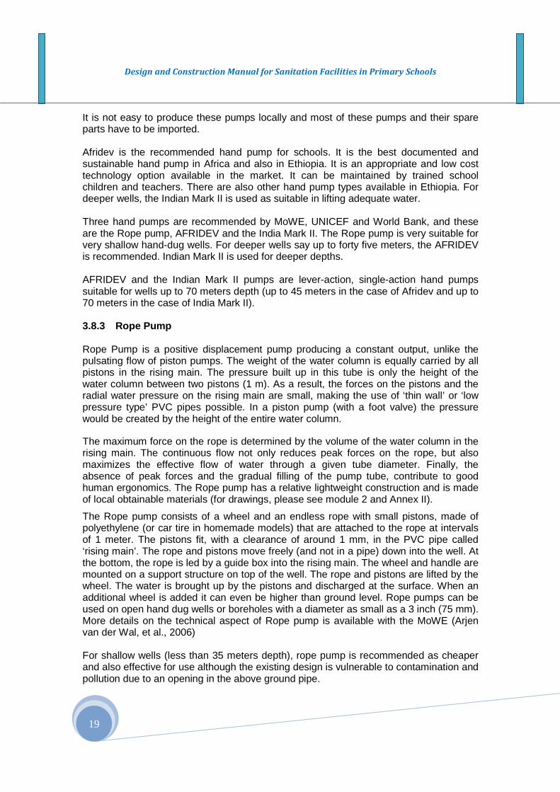
Design and Construction Manual for Sanitation Facilities in Primary Schools
19
It is not easy to produce these pumps locally and most of these pumps and their spare parts have to be imported. Afridev is the recommended hand pump for schools. It is the best documented and sustainable hand pump in Africa and also in Ethiopia. It is an appropriate and low cost technology option available in the market. It can be maintained by trained school children and teachers. There are also other hand pump types available in Ethiopia. For deeper wells, the Indian Mark II is used as suitable in lifting adequate water. Three hand pumps are recommended by MoWE, UNICEF and World Bank, and these are the Rope pump, AFRIDEV and the India Mark II. The Rope pump is very suitable for very shallow hand-dug wells. For deeper wells say up to forty five meters, the AFRIDEV is recommended. Indian Mark II is used for deeper depths. AFRIDEV and the Indian Mark II pumps are lever-action, single-action hand pumps suitable for wells up to 70 meters depth (up to 45 meters in the case of Afridev and up to 70 meters in the case of India Mark II). 3.8.3 Rope Pump Rope Pump is a positive displacement pump producing a constant output, unlike the pulsating flow of piston pumps. The weight of the water column is equally carried by all pistons in the rising main. The pressure built up in this tube is only the height of the water column between two pistons (1 m). As a result, the forces on the pistons and the radial water pressure on the rising main are small, making the use of ‘thin wall’ or ‘low pressure type’ PVC pipes possible. In a piston pump (with a foot valve) the pressure would be created by the height of the entire water column.
The maximum force on the rope is determined by the volume of the water column in the rising main. The continuous flow not only reduces peak forces on the rope, but also maximizes the effective flow of water through a given tube diameter. Finally, the absence of peak forces and the gradual filling of the pump tube, contribute to good human ergonomics. The Rope pump has a relative lightweight construction and is made of local obtainable materials (for drawings, please see module 2 and Annex II).
The Rope pump consists of a wheel and an endless rope with small pistons, made of polyethylene (or car tire in homemade models) that are attached to the rope at intervals of 1 meter. The pistons fit, with a clearance of around 1 mm, in the PVC pipe called ‘rising main’. The rope and pistons move freely (and not in a pipe) down into the well. At the bottom, the rope is led by a guide box into the rising main. The wheel and handle are mounted on a support structure on top of the well. The rope and pistons are lifted by the wheel. The water is brought up by the pistons and discharged at the surface. When an additional wheel is added it can even be higher than ground level. Rope pumps can be used on open hand dug wells or boreholes with a diameter as small as a 3 inch (75 mm). More details on the technical aspect of Rope pump is available with the MoWE (Arjen van der Wal, et al., 2006) For shallow wells (less than 35 meters depth), rope pump is recommended as cheaper and also effective for use although the existing design is vulnerable to contamination and pollution due to an opening in the above ground pipe.
Design and Construction Manual for Sanitation Facilities in Primary Schools
20
Se. No. Description No.
1 Base Assembly 1
2 Barrel Assembly 1
3 Head Assembly 1
4 Bracket 1
5 Handle Assembly 1
6 Piston Assembly 1
7 Check Value Assembly 1
8 Hex Bolt M.12 X 45 8
9 Hex Nut M-12 14
10 Washer (to suit M-12) 7

Design and Construction Manual for Sanitation Facilities in Primary Schools
21
SECTION IV: SANITARY FACILITIES IN SCHOOLS 4.1 VIP Refresher With regard to toilet in schools, this manual focuses on a simple, tried and tested design – the Ventilated Improved Pit or VIP. This is because VIP toilets are relatively simple to design, build and maintain. Their operation and cleaning uses relatively little water; certainly they do not depend on a regular water supply. The design can be adapted for different circumstances. And the resulting toilet can be relatively low cost. For almost all conditions in rural areas, VIP technology can be used. As set out in the introduction, the technology has merit in many urban settings where a reliable water supply cannot be guaranteed.
Like a simple pit, the basic VIP separates humans from excreta (urine and faeces), which fall into a pit through a drop hole. Liquid leaches through the pit walls, and solid materials break down. It is suitable for rural & semi-urban without sewer areas and for institutions like health facilities and schools. The risk of getting collapse is also medium with low smell from pit and fly nuisance. Ventilation is an integral part. Inside light system seems poor but creates good privacy for users. From durability and sustainability point of view, once it gets full, it needs to be discharged. The cost of VIP latrine are slab, net and superstructure costs and also cleaning and emptying costs if not nil as part maintenance. It is still possible to get it wrong. A VIP without a well sited vent pipe, a fly screen or adequate ventilation will not work. The pit has to be the right size. The interior may be too light (as explained, too dark may be a problem for children as well). All these problems can be seen in the field. Why - because the designer or builder has not remembered how the basic VIP works. 4.2 The Basic of VIP: How It Works F
Figure 4.1: The Basic VIP Latrine
Unlike a simple pit design, the VIP has two critical features which make it safer and less smelly. Firstly, the vent pipe causes an updraft that draws fumes up from the pit. The effect is more pronounced when wind passes over the top of the pipe, so it should extend about the roof line. As air is drawn out of the pit, it is replaced from air from the cubicle – which is effectively ventilated. Air vents must be built in to the cubicle to ensure that fresh air gets in, typically above and below the door. As simple smoke test can be used to see how the air flows - drop some smoking grass down the pit and see what happens. Secondly, whilst flies can enter the pit through the drop hole, and breed there, they cannot escape, as they are attached to the sunlight at the top of the vent pipe. This is brighter than the light entering the pipe from the drop hole. Escape from the vent pipe is prevented by a wire mesh – they fall back and die in the pit. If the interior of the cubicle is too light, flies would indeed fly up through the drop hole and out, carrying faeces with them. If the cubicle is too dark, children will be scared to use it, so the right balance has to be found.

Design and Construction Manual for Sanitation Facilities in Primary Schools
22
4.3 What Can Go Wrong in School Latrines? Basic problems encountered with the execution of this simple design include:
• The pit is too small, insufficient for the number of users, so it fills up to quickly and need emptying after only a few years
• The pit cannot be easily emptied, so the only option remaining is to seal it off and build a new toilet elsewhere
• The pit is not lined, the soil cannot take the weight of the superstructure, and the toilet superstructure collapses into the pit
• The pit walls are fully sealed – there is no provision for leaching liquid mater into the surrounding soil, as a result, the pit floods;
• Waste water is diverted into the pit, more than can be absorbed by the soil, so the pit floods.
• After excavating a hole, a single massive pit is built, rather than a number of individual pits separated by partitioning. This may save on pit lining materials, but it makes covering the pit with a slab more difficult and expensive, and significantly reduces the ventilation effect.
• The vent pipe is missing, or its diameter is too small. The pit is effectively unventilated and the toilet is very smelly. Alternatively, the vent pipe may be too short, so it does not protrude above the roof line, reducing the ventilation effect.
• No provision is made for air to get into the cubicle – again, there can be no air flow through the cubicle, which is smelly as a result.
• The fly screen is missing – so the toilet becomes a source of flies, potentially spreading disease
• The vent pipe is poorly located in the corner of the cover slab, or connected with an elbow - so little or no light penetrates the pit through the pipe. As a result, flies escape through the drop hole
• The cubicle is too bright – so flies are attached to the drop hole and make there escape. Alternatively, if the cubicle is too dark, kids are too scared to use it. A balance has to be found.
All these issues are reflected in the Sections of this manual that detail the design and construction of the school toilet itself. Understanding how a VIP works is however essential to ensure that these common problems do not occur! 4.4 Numbers, Location and Orientation Before getting into detailed design, however, we have to decide how many toilets are needed, where these should be placed, together with other facilities, and how they should be orientated – in particular, the location of entrances / exits. 4.4.1 Numbers Number in this case refers to the number of toilet stands (toilet cubicles) that are needed. The current Government norm is that applies to primary schools in Ethiopia is one stand for every 100 girls and one stand for every 150 boys, with physically separate facilities for girls and boys (Sanitation protocol, FMoH, 2005). In other African countries, design ratios of 1:50 – 1:100 are common, but these standards are not always met due to resource constraints. This is also the case in much of rural Ethiopia, where the ‘on the ground’ average is one stand per 200 students or more.

Design and Construction Manual for Sanitation Facilities in Primary Schools
23
The use of appropriately designed urinals for both girls and boys reduces the number of toilets stands needed by one third or more. This approach should be standardized in Ethiopia as it significantly reduces construction costs. In determining the number and location of toilet stands needed, planners (engineers and school authorities) should take into account the projected population of the school, with a recommended planning horizon of 3-5 years. Most primary schools in Ethiopia start off relatively ‘small’ with 250-300 students, and develop over time to around 600-750 students. The following table (Table 1) indicates the number of toilet stands required for schools of different sizes. It is based on a 1:100 toilet stand - student ratio, with both girl and boys having access to appropriate urinals. The minimum number of stands for both boys and girls is two, ensuring a degree of ‘emergency’ capacity. One important point is that the toilets provided are used by students and staff alike, with no separate facilities for teachers. This is not just a cost-saving measure. Teaching staff have an important role play in encouraging the proper use of school toilets and ensuring their upkeep. Having separate facilities for staff may undermine this responsibility.
These figures show the minimum number of toilet stands required. If resources allow, adopting a 1:50 toilet stand / student ratio is preferred, reducing pressure on toilets, increasing their fill up time, and making their upkeep easier to manage.
Box 4.1: General Design Requirements Gender Requirements: Girls and boys should be consulted about the number, location and orientation of school WASH facilities. This consultation should be organized with girls and boys separately, discussion facilitated by women and men respectively. Physically separate facilities- Separate Sanitary facilities for teachers, boys and girls. In between boys and girls, a hedge plant should be established to provide privacy for girls. The sizing and orientation of facilities – The toilet entrance should face the direction that provides the privacy, security and safety of girls. The orientation of the squatting plate, urinals, and hand washing area should also take this into account, as well as cultural and religious norms. Locations of toilets - Location of toilets for girls require special consideration in terms of providing privacy and security.
Table 4.1: Numbers of students, number of stands No of Boys Min. No. of
Stands No of Girls Min. No. of
Stands Up to 100 2 Up to 100 2
100-200 2 100-200 2 200-300 3 200-300 3 300-400 4 300-400 4
400- 500 5 400- 500 5 500-600 6 500-600 6
Design and Construction Manual for Sanitation Facilities in Primary Schools
24
4.4.2 Location Many schools were visited during the preparation of this manual. A common problem encountered concerned the location of school toilet blocks in relation to the classroom and boundary wall. The relative location of boys and girls toilets (basically, the distance between them) is also very important. Getting the location right is very important factor in ensuring that toilets are used. In line with the principles listed earlier, girls and boy students must be consulted. This consultation should be undertaken separately, the girl group led by a woman, the boys group led by a male (here it makes sense to enlist the help of teachers). Factors to consider in locating toilet blocks are set out in the following table. Inevitably, with all these factors to consider, the location of school toilets is going to be a compromise. This reinforces the necessity of consultation, with school girls and boys and their teachers. Drilling a test hole with an auger (or digging a test pit if this is not available) to see what lies underneath the surface can save considerable amount of time and money.
Table 4.2: Location Checklist
Factor Check The normal wind direction – it is best if the toilet’s vent pipes are down- wind of the classrooms � The distance from the toilet block to the class – between 30 and 50 meters if possible. More than 50 meters may be too far for a small child in a desperate hurry, and in terms of toilet management and upkeep, its best to keep the toilet nearer rather than far from the classroom
�
The distance to the boundary wall – if the toilet is placed on the boundary, there may be a risk of students extending their trip to the toilet to a trip outside the school. Equally, girls in particular may feel insecure – here its best to get their opinion
�
The need to empty toilet pits when they are full. If the sludge or compost is to be picked up by a tractor-trailer, then there needs to be enough space for vehicle access.
� The distance between the boys’ and girls’ toilets. Again, this is best fixed with consultation. 15 meters or more may be needed to secure the privacy and security needed by girls. It is also important to get the relative orientation of girls and boys toilets blocks right – see below
�
The distance to a well or borehole – a minimum of 30 meters is recommended to avoid any risk of contamination � Future plans to expand the school � Soil conditions – avoiding rocky outcrops, unstable ground conditions and depressions with a shallow water table. Here a small earth auger can be used to test ground conditions if there is any doubt
�
Drainage – ensuring that rain water does not flood the pit �

Design and Construction Manual for Sanitation Facilities in Primary Schools
25
Fig 4.2: Possible layout of school WASH Facilities
Design and Construction Manual for Sanitation Facilities in Primary Schools
26
4.3 Orientation Other than location, it is very important to get the orientation of the toilet blocks right as well. Social and cultural considerations are paramount – so again, it’s important to consult with boys and girls. In particular, this concerns the direction the toilets (and here we mean the toilets’ entrance) faces. For example, if the entrance of a girl’s toilet is opposite a classroom or the entrance to the boys’ toilet, girls may not want to use it. Alternatively, if the entrance faces a nearby boundary wall, boys and girls may feel insecure for another set of reasons. Orientation, like location, is case specific, but consultation is critical to encourage rather than discourage the use of toilets. Figure 4 above shows one possible layout of school WASH facilities. There is no blueprint, but the changes of the toilets being used are much higher if the guidance set out above is followed. Inside the toilet block, the orientation of the squatting slab is also important, for example, respecting religious norms. This issue is dealt with later.
4.5 The different types of school toilets 4.5.1 Introduction The National Sanitation and Hygiene Strategy require that institutional sanitation facilities must be composting type, and this manual gives emphasis to this type of latrines. Hence the manual recommends the use of composting VIP latrine for schools while other options are still open and discussed here as well. The selection of VIP latrines for certain local conditions and environments are presented in the table below. The table will help guide the selection of latrine that is appropriate to certain situations and environments.
Table 4 .3: Suggested types of latrines to certain local situ ations
Situations Type of School Toilet
“Shallow” VIP (1.5 to 3 m ) “Deep Pit” VIP (>4 m)
High ground water table Raised floor design5 Not appropriate Areas prone to floods Raised floor design Raised floor design Hard rock geology Raised floor design Not suitable Unstable and low permeability soils
Pit wall must have slope and lined with dry masonry
Pit wall must have slope and lined with dry masonry
Stable soil, gravel and coarse material
Appropriate and with composting type design
Appropriate
Dry and stable soil Composting type Appropriate In areas where the latrines are prone to seasonal flooding, or where water table is very shallow, the solution is to build raised latrine and make the latrine pit watertight. The latrines pits need to be raised and sealed to stop the sewage mixing with the ground water and polluting ground water sources. In order to do that the pit walls could be constructed with cement plastered. In section five, the different latrine design and construction will be discussed in detail.
5 Raise the surface of the latrine floor by up to 100 cm and underground pit depth of 150 cm.

Design and Construction Manual for Sanitation Facilities in Primary Schools
27
4.5.2 The “Deep Pit” Non-Composting VIP Toilet In rural areas where land for latrine construction is not a constraint and it is technically and financially feasible, “deep pit non composting VIP toilets” can be used. This section focuses on the design and construction of what is the most common and probably most useful school toilet type, the conventional VIP deep pit. It is designed to reduce two of the problems frequently encountered by traditional latrine systems, namely their smell and their insect production. A conventional VIP deep pit latrine differs from traditional latrine by a vent pipe covered with a fly screen. Wind blowing across the top of the vent pipe creates a flow of air which sucks out the foul smelling gasses from the pit. As a result fresh air is drawn in to the pit through the drop hole and the superstructure is kept free from smells. The vent pipe also has an important role to play in fly control. Flies are attracted to light and if the latrine is suitable dark inside they will fly up the vent pipe to the light. They cannot escape because of the fly screen, so they are trapped at the top of the pipe until they dehydrate and die. Female flies, searching for an egg-laying site, are attracted by the odours from the vent pipe but are prevented from lying by the fly screen at its top.
Although this toilet is relatively common, so there are also associated with its design and construction. Many of these are fundamental (see Section 1: What can go wrong?). Other problems concern detail, for example, ensuring adequate ventilation or the detailed design or finishing of the squatting plate.
The heart of a pit latrine is its superstructure – the bit that’s under the ground. It is critical to get this bit right, as any mistake may be impossible or very expensive – to fix when the superstructure, the above ground part of the toilet, is finished. In particular, the pit has to be the right shape and size. Too small, it will full up too quickly; too big, and the cost of excavation and construction will be prohibitive.
Box 4.2: Key Principles WASH structure in schools: They must be safe for users to use - in terms of the structural stability; in terms of a child not being able to fall through an oversized drop hole; in terms of children not risking abuse, bullying or attack when approaching, using or leaving the facilities provided Detailed design of the toilet: It must be child friendly. Steps must be easy to climb. Door handles must be easy to reach. The toilet interior cannot be too dark. Squatting plates must be designed to accommodate a child’s feet rather than those of an adult. Surfaces must be easy to clean. The drop hole must be correctly sized. Too large, it may be unsafe. Too small, cleaning will be needed after every visit. Ventilation is important to minimize any smell. Address the need of children with physical disabili ties: Facilities provided must include provision for disabled children, with at least one cubicle for girls and one for boys arranged accordingly. In terms of design, ramps and hand rails should be provided, with more internal space for a caregiver to assist if necessary. Disabled girls and boys should be consulted with their able bodied peers to get the design right.

Design and Construction Manual for Sanitation Facilities in Primary Schools
28
4.5.3 Sizing the Pit
It is important that designers, builders and the school authorities understand how the pit size is calculated. This is set out in Box 1 below. The calculation is relatively simple, and is based on a number of tried and tested assumptions. A different set of assumptions are used in the design of an alternating twin pit toilet (see Section 6).
The basic assumptions used here are: (i) The toilet is designed for 100 students per toilet stand (each with its own pit
underneath) – taking into account the associated use of urinals (ii) The toilet is designed for a minimum five year fill time (iii) The school is open for 200 days a year (iv) The pit area under each stand is set at 1.1 meters wide, 2.6 meters long (v) The average volume of excreta amounts to 25 liters per child per year, measured
over the five years. This allows for (i) materials used for anal cleansing (ii) volume reduction due to decomposition over the 5 year period and (iii) the fact that the child will also defecate at or near home, either before or after the school day 6
(vi) The average volume of fluid entering the toilet (urine and cleaning water) is 1 liter per child per day, of which 50% evaporates or percolates through the bottom of the pit
(vii) The infiltration rate of the soil is assumed to be 25 liters per meters square 2/ (this being side wall area) per day – equivalent to a sandy loam soil (See section 7). Soils with more clay will need connection to a soak pit or infiltration trench
Based on these assumptions the depth of the pit can be calculated as presented in Box 4.3 below.
Box 4.3: Calculating Pit Depth ‘D’ Solids A. In one full year, volume of sludge = 100 students x 25 litres = 2,500 litres B. In 5 school years, volume of sludge = 5 x 2,500 x (200/365) = 6,850 litres C. Assumed pit area of 1.2 x 2.6 meters = 3.12 m2 D. Resulting depth of sludge (D1) = 6,850 / 3.12 = 2.195 meters Liquids A. In one day, amount of liquid entering the pit is 1 litre per student = 100 litres. Of this,
50% is lost by evaporation and deep percolation, leaving 50 litres B. Assumed infiltration rate of soil: 25 l / m2 / day C. Wall area need to infiltrate liquid = 2 m2 D. Additional depth of pit needed to infiltrate liquid (H2) = 4 / (1.2+1.2+2.6+2.6)
D2 = 0.26 meters Freeboard A. Additional safe space above solid and liquid below the slab: Minimum Freeboard
(D3) = 0.5 meters (given) Total Depth of Pit (D) = 2.195 + 0.26+ 0.5 = 2.955 (rounded up to 3m)
6/ Compare this to a figure of 20-60 liters per adult per year (Franceys et al, 1992)

Design and Construction Manual for Sanitation Facilities in Primary Schools
29
The total pit depth ‘D’ required has to allow for (i) containment of accumulated solids, D1; (ii) the infiltration of liquid through side walls D2 and (iii) a reasonable free space (freeboard) beneath the toilet squatting plate, D3, 0.5 meters being used here. The total pit depth H is the sum of D1, D2 and D3 (Figure 5 below). The depth of pit needed is therefore just over 3 meters for a five year fill time. Further deepening the pit will add to the fill time as set out in Table 3 below, but it also adds significantly to the difficulty and cost of excavation – as well as the risk of collapse to the laborers excavating the pit and the risks on contaminating shallow ground water.
Figure 4.3: Determining Pit Depth ‘D’
Table 4.4: Pit Depth versus Fill Time
Pit Depth Fill Time 3 meters 5 years 4 meters 7.5 years 5 meters 10 years
Ground water contamination is a potential health threat if the bottom of the pit is within two meters of the ground water table. To be safe, the toilet pits should not be located with 30 meters of any water source drawing ground water (such as a hand dug well). If the soil in which the pit is being sunk has a lot of clay in it, then there may be a problem with its capacity to infiltrate liquid (urine and water for cleaning). In this situation, a 75 or 110 mm diameter overflow pipe should be included in the pit design, ensuring

Design and Construction Manual for Sanitation Facilities in Primary Schools
30
that excess liquid is drained to a soak pit or infiltration trench adjacent to the toilet. In terms of excavation, the ‘standard pit’ should be three meters deep. The pit width is set at 3 meters, enough to ensure an internal width of 2.6 meters after lining. The pit length is of course variable, determined by the number and width of the toilet stands needed, and the width of the blocks used to line it. The urine and waste water drains into a physically separate soak pit or infiltration trench at least 5 meters away. The minimum dimensions of the excavated pit, in this case sized for a 4 stand (i.e. a 4 partitions or cubicle) toilet, are shown below in Figure 6. This information is summarized in Table 4, which includes basic pit dimensions for 2, 3, 5, and 6 stand designs.
Figure 4.4: Minimum Pit Dimensions for 4 stand deep pit toilet
Table 4.5: Minimum Pit Dime nsions (excavated size) for different toilet config urations, Note that space limitations normally prevent extens ion beyond a 6 stand design
Configuration Excavated Length in m
Excavated Width in m
Excavated Depth in m
2 stand 3.8 3 3 3 stand 5.3 3 3 4 stand 6.8 3 3 5 stand 8.3 3 3 6 stand 9.8 3 3
4.6 Composting Type Alternating “Twin Pit” VIP Scho ol Toilet
4.6.1 Description
The previous section focused on a remarkably simple, conventional ‘deep pit’ technology, with provision at the back of the toilet superstructure for emptying the pits every five years or so. The problem is that in a significant minority of cases, it is not practical to sink a pit by the required 3 meters or more. For example, after a meter or so
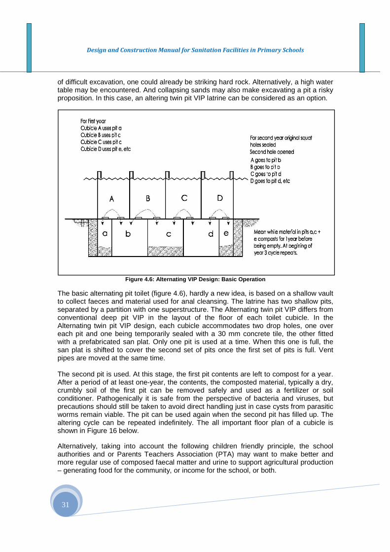
Design and Construction Manual for Sanitation Facilities in Primary Schools
31
of difficult excavation, one could already be striking hard rock. Alternatively, a high water table may be encountered. And collapsing sands may also make excavating a pit a risky proposition. In this case, an altering twin pit VIP latrine can be considered as an option.
Figure 4.6: Alternating VIP Design: Basic Operation
The basic alternating pit toilet (figure 4.6), hardly a new idea, is based on a shallow vault to collect faeces and material used for anal cleansing. The latrine has two shallow pits, separated by a partition with one superstructure. The Alternating twin pit VIP differs from conventional deep pit VIP in the layout of the floor of each toilet cubicle. In the Alternating twin pit VIP design, each cubicle accommodates two drop holes, one over each pit and one being temporarily sealed with a 30 mm concrete tile, the other fitted with a prefabricated san plat. Only one pit is used at a time. When this one is full, the san plat is shifted to cover the second set of pits once the first set of pits is full. Vent pipes are moved at the same time. The second pit is used. At this stage, the first pit contents are left to compost for a year. After a period of at least one-year, the contents, the composted material, typically a dry, crumbly soil of the first pit can be removed safely and used as a fertilizer or soil conditioner. Pathogenically it is safe from the perspective of bacteria and viruses, but precautions should still be taken to avoid direct handling just in case cysts from parasitic worms remain viable. The pit can be used again when the second pit has filled up. The altering cycle can be repeated indefinitely. The all important floor plan of a cubicle is shown in Figure 16 below. Alternatively, taking into account the following children friendly principle, the school authorities and or Parents Teachers Association (PTA) may want to make better and more regular use of composed faecal matter and urine to support agricultural production – generating food for the community, or income for the school, or both.

Design and Construction Manual for Sanitation Facilities in Primary Schools
32
Whilst those more used to urban living may turn their noses up at this argument, it should be recalled that tens of millions of rural people and thousands of farming communities across Asia depend on recycling human waste to enhance crop production – just as many farmers do in developed countries with larger urban populations.
Box 4.5: Key Principles Environmental sustainability : It should be an integral part of the design, implementation, operation, and maintenance of sanitary facilities. The challenge is to promote awareness of the environmental issues surrounding water, sanitation, and hygiene in schools, while providing incentives and tools to address them. In a learning environment, it is important to reduce the negative environmental effects and hazards to public health at the same time. Minimize smell and problems of drainage: The problem of smell and drainage from a relatively small pit, urinals should be used to the extent possible by girls as well as boys (Section 7), and care should be taken to avoid flooding the pit with water used for cleaning. Urine, waste water and grey water from hand washing is in fact channeled to a separate leach pit or infiltration trench in this design, just as it is in the design featured in Section 3. Use of urine, waste water and composted faecal matt er: It is relatively simple to modify the design of the leach pit and use the urine / water collected as a potent fertilizer. Once in operation systematic quality monitoring has to be taken place in the use of urine, waste water and composted faecal matter from toilet pits to support agricultural production for its quality before official handing-over of the facility. More detail of how to do this are to be included in the next edition of this manual, together with other eco-friendly designs. The basic alternating twin pit VIP concept in a school setting is shown in Figure 15.
Figure 4.5: Floor Layout – Alternating Twin Pit
1.2m or 1.5m
1.8m
San plat (60x60)
Fill area A+B with
weak cement mortar
to same level to aid
cleaning
Tile over
second drop
hole
DrainDirection
B
A
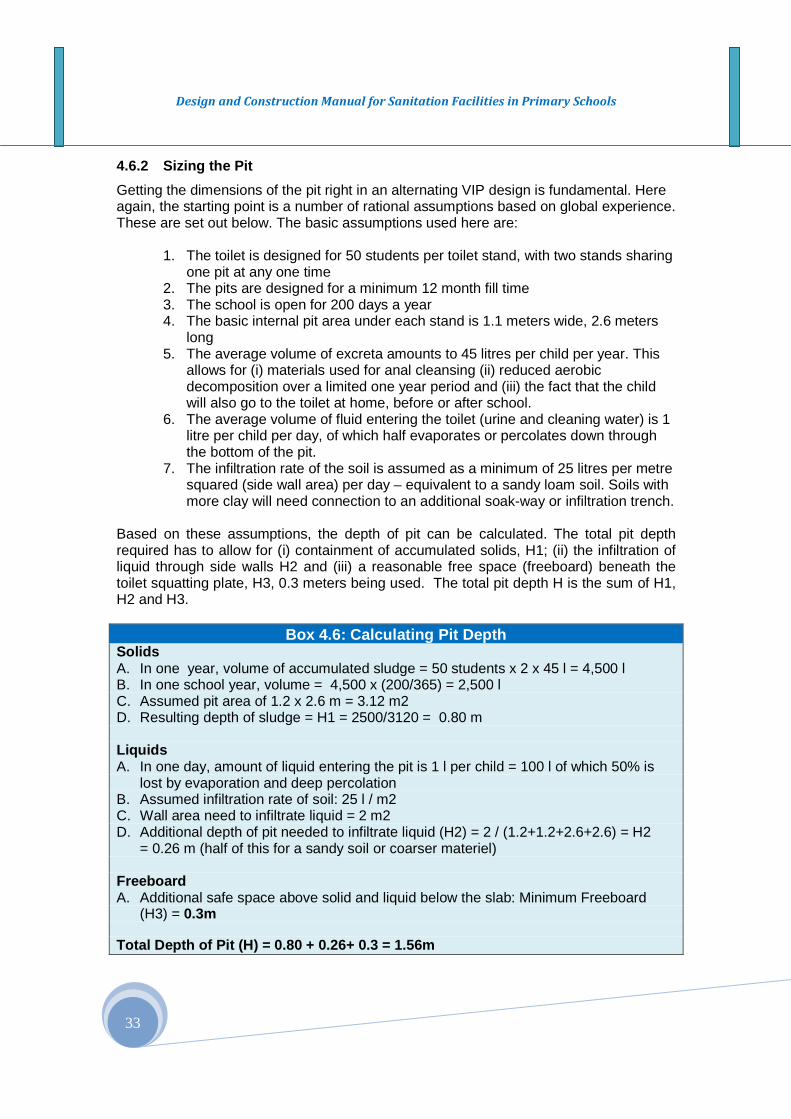
Design and Construction Manual for Sanitation Facilities in Primary Schools
33
4.6.2 Sizing the Pit
Getting the dimensions of the pit right in an alternating VIP design is fundamental. Here again, the starting point is a number of rational assumptions based on global experience. These are set out below. The basic assumptions used here are:
1. The toilet is designed for 50 students per toilet stand, with two stands sharing one pit at any one time
2. The pits are designed for a minimum 12 month fill time 3. The school is open for 200 days a year 4. The basic internal pit area under each stand is 1.1 meters wide, 2.6 meters
long 5. The average volume of excreta amounts to 45 litres per child per year. This
allows for (i) materials used for anal cleansing (ii) reduced aerobic decomposition over a limited one year period and (iii) the fact that the child will also go to the toilet at home, before or after school.
6. The average volume of fluid entering the toilet (urine and cleaning water) is 1 litre per child per day, of which half evaporates or percolates down through the bottom of the pit.
7. The infiltration rate of the soil is assumed as a minimum of 25 litres per metre squared (side wall area) per day – equivalent to a sandy loam soil. Soils with more clay will need connection to an additional soak-way or infiltration trench.
Based on these assumptions, the depth of pit can be calculated. The total pit depth required has to allow for (i) containment of accumulated solids, H1; (ii) the infiltration of liquid through side walls H2 and (iii) a reasonable free space (freeboard) beneath the toilet squatting plate, H3, 0.3 meters being used. The total pit depth H is the sum of H1, H2 and H3.
Box 4.6: Calculating Pit Depth Solids A. In one year, volume of accumulated sludge = 50 students x 2 x 45 l = 4,500 l B. In one school year, volume = 4,500 x (200/365) = 2,500 l C. Assumed pit area of 1.2 x 2.6 m = 3.12 m2 D. Resulting depth of sludge = H1 = 2500/3120 = 0.80 m Liquids A. In one day, amount of liquid entering the pit is 1 l per child = 100 l of which 50% is
lost by evaporation and deep percolation B. Assumed infiltration rate of soil: 25 l / m2 C. Wall area need to infiltrate liquid = 2 m2 D. Additional depth of pit needed to infiltrate liquid (H2) = 2 / (1.2+1.2+2.6+2.6) = H2
= 0.26 m (half of this for a sandy soil or coarser materiel) Freeboard A. Additional safe space above solid and liquid below the slab: Minimum Freeboard
(H3) = 0.3m Total Depth of Pit (H) = 0.80 + 0.26+ 0.3 = 1.56m
Design and Construction Manual for Sanitation Facilities in Primary Schools
34
Notes: The calculation in Box 4.6 above is based on a fairly impermeable soil with a relatively low infiltration rate of 25 litres / meter 2 / day. If the soil type has a higher infiltration rate, the pit volume (depth) can be reduced. Alternatively, a drain pipe can be included in the design of the pit, falling to a separate infiltration trench. The figure of 45 litres (annual accumulation rate per student) is much more than the equivalent figure of 15 litres per year used for the deep pit calculation. This is because the excreta have only one year to degrade / decompose, compared to five years or more in the deep pit design. Finally, to ensure that the pit is filled efficiently, every 3 months, the pit access cover at the back of the pit should be removed and the contents raked back. Alternating Twin Pit VIPs have a greater need to periodic maintenance as a result, although the task is relatively simple to perform. 4.7 Hand Washing Practice in schools
The hands of school children get in contact with a lot of dirty substances and particularly after using the school latrines. Hand washing with soap or ash is, therefore, important for removing pathogens of their hands and protects and improves their health. In a recent review and study conducted on the impact of washing hands with soap on the risk of diarrhea, Curtis and Cairncross, 2003 found that washing hands with soap can reduce the risk of diarrhea by 42 to 47 percent. The same study highlighted that hand washing is also important in the prevention of acute respiratory infections. Most schools in Ethiopia do not provide appropriate hand washing facilities and proper hygiene education. Where these facilities are available, they may be poorly located, or do not have sufficient water and soap or ash for hand washing.
Design and Construction Manual for Sanitation Facilities in Primary Schools
35
SECTION V: CHILD FRIENDLY DESIGN AND CONSTRUCTION OF SANITARY AND HYGIENE FACILITIES
5.1 VIP Latrine Design The detail design sketched of the VIP latrine is provided in the Annex. Other than the pit dimensions, many aspects of the design and construction are the same for both selected technology options (the conventional deep pit VIP and the altering twin pit VIP latrines). There are some aspects local environments which also influence and dictate the design. These include the level of the ground water, soil type (unstable and collapsing), and rocky ground, etc. In areas where the water table is very high or where there are annual floods, the latrines must be built high enough so that the floods do not make the latrine content flow out of the pits, creating very serious risks for the spread of diseases. If the soil is unstable, a masonry structure may be required. If the ground is rocky, the depth could be developed above the ground. Thus the school latrines should be designed taking into account of the above design factors. 5.2 Construction Having selected the most appropriate sanitation facility design, construction will have to be organized, whereby choices will have to be made about the level of involvement of the school communities; school administration, school children, PTA, and other stakeholders. This basically boils down to comparing the financial means needed to pay outsiders and the opportunity costs of construction by students, teachers and community members. Whichever option is chosen, involvement of the school community in any decision to be taken is important if facilities are to be used. As sanitary facilities are an essential part of schools, their operation and maintenance should be included in the management plan. However, construction of facilities are usually not included in a school's annual plan and therefore do not appear in the budget.
5.2.1 Safe Excavation
Digging a pit of this size can be tricky, even dangerous, and Box 7 below outlines some simple precautions that should be observed 5.2.2 Bottom of the Pit The bottom of the pit should be sloped with a 10 - 20 cm (5-10%) fall towards its back wall. This is to help distribute excreta evenly and fill the pit efficiently. 5.2.3 Lining the Pit and Partition Once the pit is excavated, the next step is to line it. ALL SCHOOL TOILET PITS MUST BE FULLY LINED REGARDLESS OF THE SOIL TYPE. This is because the toilet is designed to last ten years or more, the pit is designed to be emptied every five years or so, and the superstructure itself is heavy and has to be well supported. A school toilet also has to be safe. School toilets with unlined pits are prone to collapse, risking the lives of children using it.
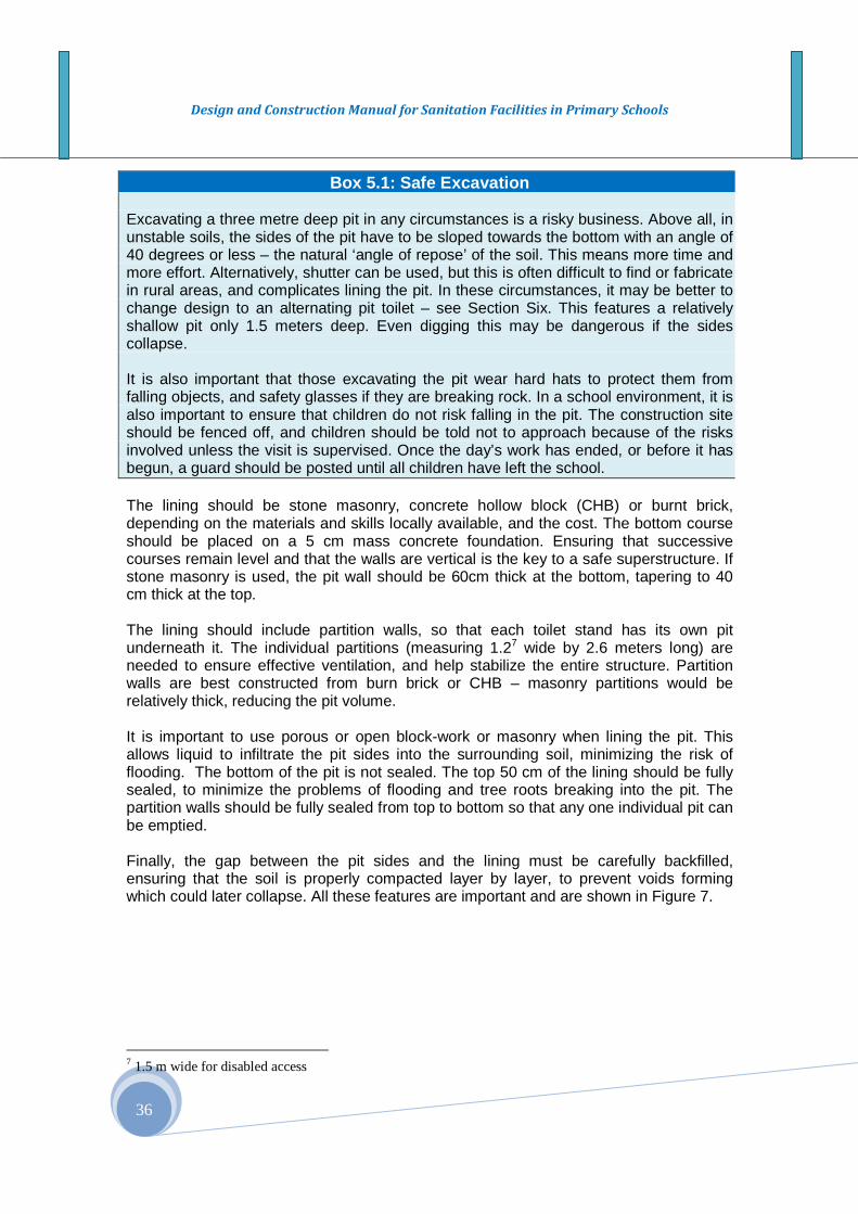
Design and Construction Manual for Sanitation Facilities in Primary Schools
36
Box 5.1: Safe Excavation Excavating a three metre deep pit in any circumstances is a risky business. Above all, in unstable soils, the sides of the pit have to be sloped towards the bottom with an angle of 40 degrees or less – the natural ‘angle of repose’ of the soil. This means more time and more effort. Alternatively, shutter can be used, but this is often difficult to find or fabricate in rural areas, and complicates lining the pit. In these circumstances, it may be better to change design to an alternating pit toilet – see Section Six. This features a relatively shallow pit only 1.5 meters deep. Even digging this may be dangerous if the sides collapse. It is also important that those excavating the pit wear hard hats to protect them from falling objects, and safety glasses if they are breaking rock. In a school environment, it is also important to ensure that children do not risk falling in the pit. The construction site should be fenced off, and children should be told not to approach because of the risks involved unless the visit is supervised. Once the day’s work has ended, or before it has begun, a guard should be posted until all children have left the school. The lining should be stone masonry, concrete hollow block (CHB) or burnt brick, depending on the materials and skills locally available, and the cost. The bottom course should be placed on a 5 cm mass concrete foundation. Ensuring that successive courses remain level and that the walls are vertical is the key to a safe superstructure. If stone masonry is used, the pit wall should be 60cm thick at the bottom, tapering to 40 cm thick at the top. The lining should include partition walls, so that each toilet stand has its own pit underneath it. The individual partitions (measuring 1.27 wide by 2.6 meters long) are needed to ensure effective ventilation, and help stabilize the entire structure. Partition walls are best constructed from burn brick or CHB – masonry partitions would be relatively thick, reducing the pit volume. It is important to use porous or open block-work or masonry when lining the pit. This allows liquid to infiltrate the pit sides into the surrounding soil, minimizing the risk of flooding. The bottom of the pit is not sealed. The top 50 cm of the lining should be fully sealed, to minimize the problems of flooding and tree roots breaking into the pit. The partition walls should be fully sealed from top to bottom so that any one individual pit can be emptied. Finally, the gap between the pit sides and the lining must be carefully backfilled, ensuring that the soil is properly compacted layer by layer, to prevent voids forming which could later collapse. All these features are important and are shown in Figure 7.
7 1.5 m wide for disabled access

Design and Construction Manual for Sanitation Facilities in Primary Schools
37
Figure 5.1: Details of completed sub-structure, 4 s tand deep VIP latrine
5.2.4 Toilet Superstructure
5.2.4.1 Basic Having completed the substructure, the next stage is to complete the toilet superstructure. This lies on top of the sub-structure. There are two options here, depending if the doors of the toilet cubicles are to open inwards or outwards. If the doors open inwards, more space is required in the cubicle to allow for it to swing open, leaving space for the user to enter and close the door without tripping up on the squatting plate towards the back of the cubicle. The added length adds to construction costs. The advantage of an in-swinging door is that these are much less vulnerable to wind damage. And a toilet with damaged or missing doors is unlikely to be used. The alternative is to arrange the doors to open outwards, saving on space, materials and costs, but risking damage to the doors if they are not properly secured. The design in Section 7 is based on the in-swinging arrangement. 5.2.4.2 Grade Beam and Slab Design Layout The increased length of floor needed is achieved by extending the reinforced concrete grade beam that covers the pit wall by 60 cms to the front of the toilet. The beam, measuring 150 mm thick, provides a stable, level platform on which to lay the floor slab
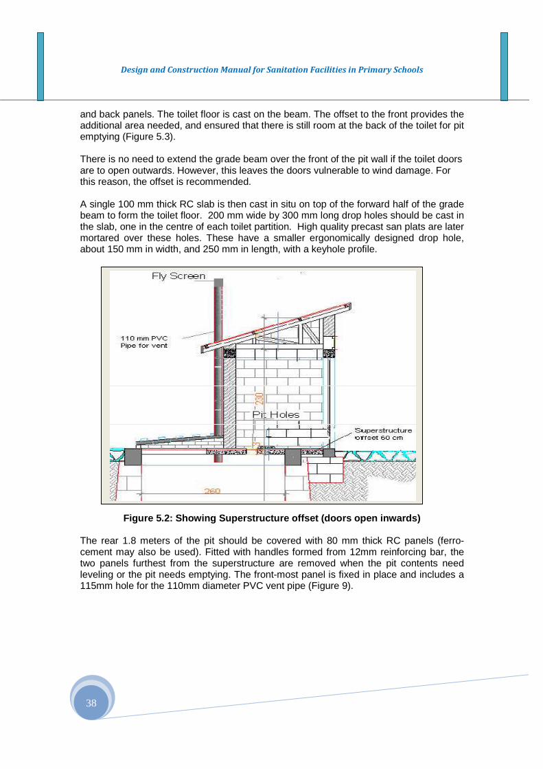
Design and Construction Manual for Sanitation Facilities in Primary Schools
38
and back panels. The toilet floor is cast on the beam. The offset to the front provides the additional area needed, and ensured that there is still room at the back of the toilet for pit emptying (Figure 5.3). There is no need to extend the grade beam over the front of the pit wall if the toilet doors are to open outwards. However, this leaves the doors vulnerable to wind damage. For this reason, the offset is recommended. A single 100 mm thick RC slab is then cast in situ on top of the forward half of the grade beam to form the toilet floor. 200 mm wide by 300 mm long drop holes should be cast in the slab, one in the centre of each toilet partition. High quality precast san plats are later mortared over these holes. These have a smaller ergonomically designed drop hole, about 150 mm in width, and 250 mm in length, with a keyhole profile.
Figure 5.2: Showing Superstructure offset (doors op en inwards) The rear 1.8 meters of the pit should be covered with 80 mm thick RC panels (ferro-cement may also be used). Fitted with handles formed from 12mm reinforcing bar, the two panels furthest from the superstructure are removed when the pit contents need leveling or the pit needs emptying. The front-most panel is fixed in place and includes a 115mm hole for the 110mm diameter PVC vent pipe (Figure 9).
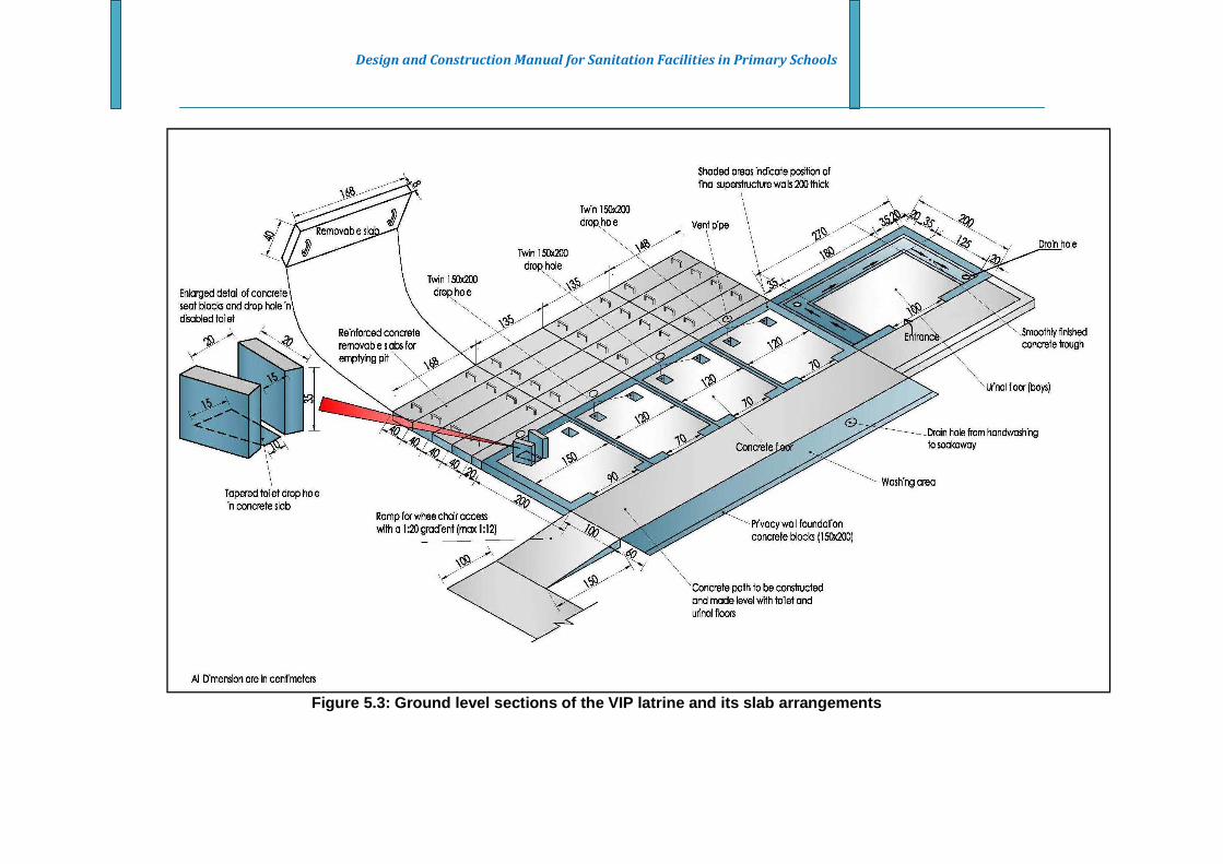
Design and Construction Manual for Sanitation Facilities in Primary Schools
Figure 5.3: Ground level sections of the VIP latrin e and its slab arrangements
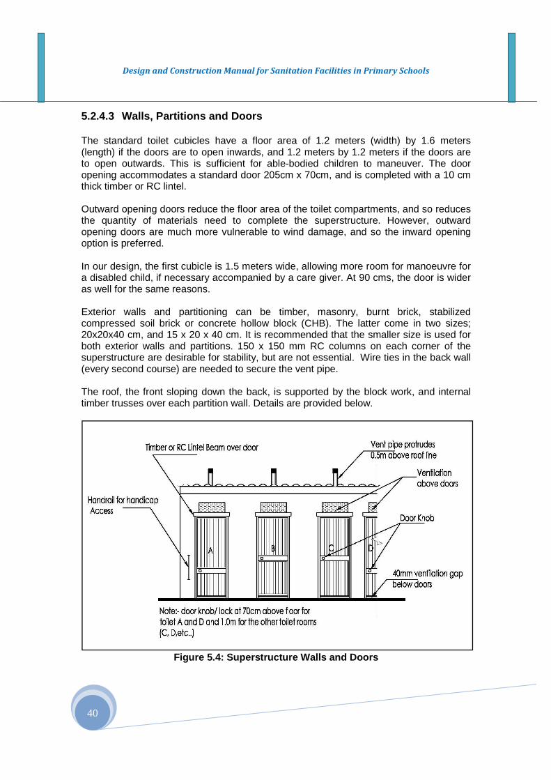
Design and Construction Manual for Sanitation Facilities in Primary Schools
40
5.2.4.3 Walls, Partitions and Doors The standard toilet cubicles have a floor area of 1.2 meters (width) by 1.6 meters (length) if the doors are to open inwards, and 1.2 meters by 1.2 meters if the doors are to open outwards. This is sufficient for able-bodied children to maneuver. The door opening accommodates a standard door 205cm x 70cm, and is completed with a 10 cm thick timber or RC lintel. Outward opening doors reduce the floor area of the toilet compartments, and so reduces the quantity of materials need to complete the superstructure. However, outward opening doors are much more vulnerable to wind damage, and so the inward opening option is preferred. In our design, the first cubicle is 1.5 meters wide, allowing more room for manoeuvre for a disabled child, if necessary accompanied by a care giver. At 90 cms, the door is wider as well for the same reasons. Exterior walls and partitioning can be timber, masonry, burnt brick, stabilized compressed soil brick or concrete hollow block (CHB). The latter come in two sizes; 20x20x40 cm, and 15 x 20 x 40 cm. It is recommended that the smaller size is used for both exterior walls and partitions. 150 x 150 mm RC columns on each corner of the superstructure are desirable for stability, but are not essential. Wire ties in the back wall (every second course) are needed to secure the vent pipe. The roof, the front sloping down the back, is supported by the block work, and internal timber trusses over each partition wall. Details are provided below.
Figure 5.4: Superstructure Walls and Doors

Design and Construction Manual for Sanitation Facilities in Primary Schools
41
As already mentioned, doors are an important component of most school toilets, essential to guarantee privacy and security for the user. Treated timber is preferred to steel. A standard 205mm x 70 mm door is recommended, with two or more hinges. The standard door frame measures 210cms high, resulting in a 40 mm air gap underneath the door for ventilation. The end cubicle should include a wider door, 90 cm rather than 70 cm wide (Figure 5.3), providing more room for a disabled user and caregiver. 4.2.4.4 Privacy Wall A privacy wall, 1.5 meters high is placed 1.4 meters in front of the toilet partitions. The privacy wall in the girl’s toilet block is closed at the end of the structure. This provides more security for girls using the urinal, and more privacy for washing (Figure 5.5). The design of the wall can be made open block, saving blocks, affording limited visibility and making the exterior of the toilet more welcoming. The design and the height of the wall, needs to be finalized with the participation of students, however. 4.2.4.5 Roof and Vent Pipe The roof, sloping down from front to back, is covered with galvanized Corrugated Iron Sheet (CIS). A minimum 32 gauge Corrugated Iron Sheet (CIS) is recommended. Seasoned eucalyptus wood is recommended for the timber frame (see Figure 5.6), which fastened to the top of the partition walls with 4 mm tie bar. The roof is supported on block-work at each end of the toilet block and over the lintel. Three courses of block work extend from the lintel to the top of the frame above the door, raising the roofline by 70 cms. A 40 cm high, 80 cm wide gap provides additional ventilation and ensures that the toilet partitions are not too dark to discourage their use. The ventilation gap may be completed with a 40 mm square chicken mesh to keep birds out.
Figure 5.5: Privacy Wall
Latrine for Boys
Latrine for Girls
Privacy wall
Privacy wall
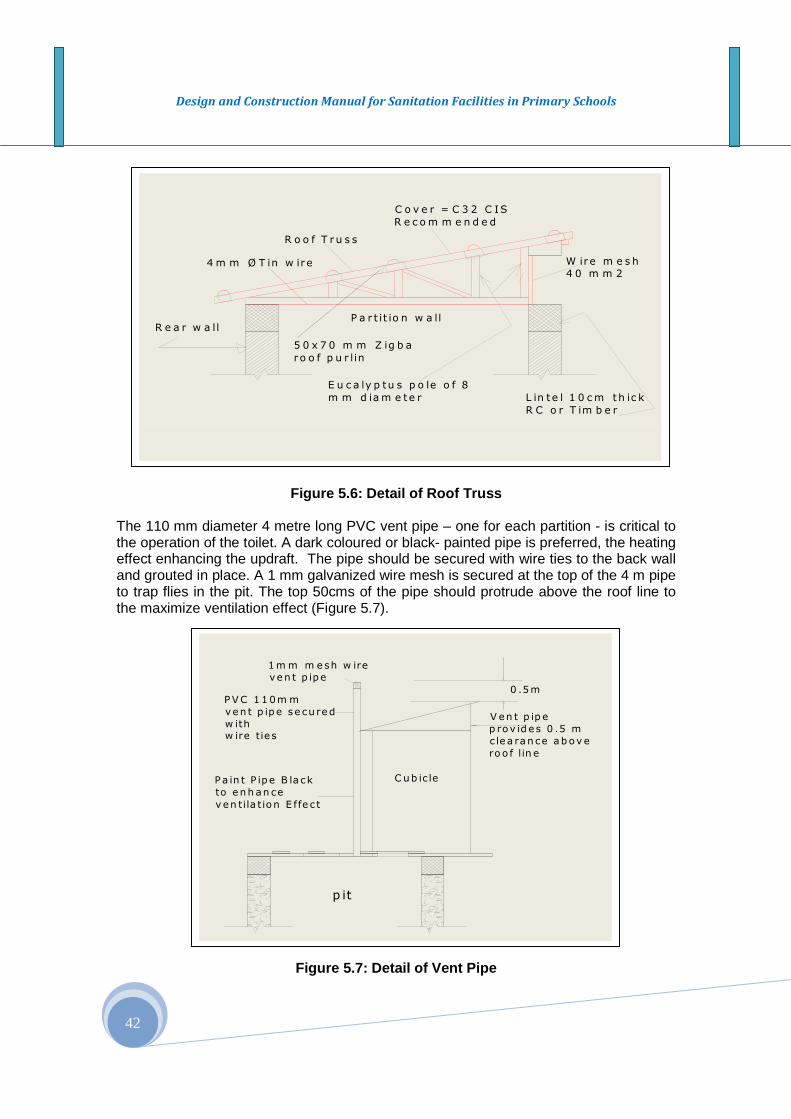
Design and Construction Manual for Sanitation Facilities in Primary Schools
42
Figure 5.6: Detail of Roof Truss The 110 mm diameter 4 metre long PVC vent pipe – one for each partition - is critical to the operation of the toilet. A dark coloured or black- painted pipe is preferred, the heating effect enhancing the updraft. The pipe should be secured with wire ties to the back wall and grouted in place. A 1 mm galvanized wire mesh is secured at the top of the 4 m pipe to trap flies in the pit. The top 50cms of the pipe should protrude above the roof line to the maximize ventilation effect (Figure 5.7).
Figure 5.7: Detail of Vent Pipe
R o o f T r u s s
4 m m Ø T in w ir e
R e a r w a llP a r t it io n w a ll
L in t e l 1 0 cm th ic k
R C o r T im b e r
W ire m e s h4 0 m m 2
C o v e r = C 3 2 C IS
R e c o m m e n d e d
E u c a ly p tu s p o le o f 8
m m d iam e te r
5 0 x 7 0 m m Z ig b a
ro o f p u r l in
Pa in t P ipe B la ck
to e nh an ce
v en tila t ion E ffe c t
1m m m esh w ireven t p ipe
PVC 1 10m m
ven t p ipe se cu red
w ithw ire tie s
0 .5m
V en t p ip e
p rov id es 0 .5 m
c le a ran ce ab ove
ro o f lin e
C ub ic le
p it
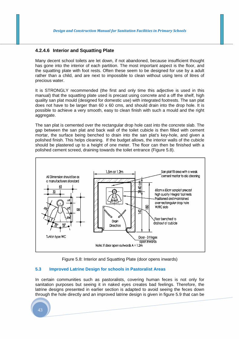
Design and Construction Manual for Sanitation Facilities in Primary Schools
43
4.2.4.6 Interior and Squatting Plate Many decent school toilets are let down, if not abandoned, because insufficient thought has gone into the interior of each partition. The most important aspect is the floor, and the squatting plate with foot rests. Often these seem to be designed for use by a adult rather than a child, and are next to impossible to clean without using tens of litres of precious water. It is STRONGLY recommended (the first and only time this adjective is used in this manual) that the squatting plate used is precast using concrete and a off the shelf, high quality san plat mould (designed for domestic use) with integrated footrests. The san plat does not have to be larger than 60 x 60 cms, and should drain into the drop hole. It is possible to achieve a very smooth, easy to clean finish with such a mould and the right aggregate. The san plat is cemented over the rectangular drop hole cast into the concrete slab. The gap between the san plat and back wall of the toilet cubicle is then filled with cement mortar, the surface being benched to drain into the san plat’s key-hole, and given a polished finish. This helps cleaning. If the budget allows, the interior walls of the cubicle should be plastered up to a height of one meter. The floor can then be finished with a polished cement screed, draining towards the toilet entrance (Figure 5.8).
Figure 5.8: Interior and Squatting Plate (door opens inwards)
5.3 Improved Latrine Design for schools in Pastor alist Areas In certain communities such as pastoralists, covering human feces is not only for sanitation purposes but seeing it in naked eyes creates bad feelings. Therefore, the latrine designs presented in earlier section is adapted to avoid seeing the feces down through the hole directly and an improved latrine design is given in figure 5.9 that can be
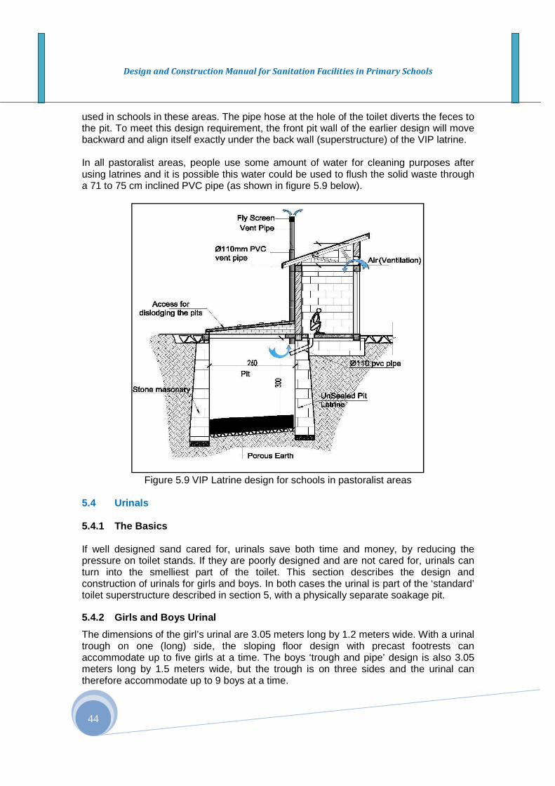
Design and Construction Manual for Sanitation Facilities in Primary Schools
44
used in schools in these areas. The pipe hose at the hole of the toilet diverts the feces to the pit. To meet this design requirement, the front pit wall of the earlier design will move backward and align itself exactly under the back wall (superstructure) of the VIP latrine. In all pastoralist areas, people use some amount of water for cleaning purposes after using latrines and it is possible this water could be used to flush the solid waste through a 71 to 75 cm inclined PVC pipe (as shown in figure 5.9 below).
Figure 5.9 VIP Latrine design for schools in pastoralist areas
5.4 Urinals 5.4.1 The Basics If well designed sand cared for, urinals save both time and money, by reducing the pressure on toilet stands. If they are poorly designed and are not cared for, urinals can turn into the smelliest part of the toilet. This section describes the design and construction of urinals for girls and boys. In both cases the urinal is part of the ‘standard’ toilet superstructure described in section 5, with a physically separate soakage pit.
5.4.2 Girls and Boys Urinal
The dimensions of the girl’s urinal are 3.05 meters long by 1.2 meters wide. With a urinal trough on one (long) side, the sloping floor design with precast footrests can accommodate up to five girls at a time. The boys ‘trough and pipe’ design is also 3.05 meters long by 1.5 meters wide, but the trough is on three sides and the urinal can therefore accommodate up to 9 boys at a time.
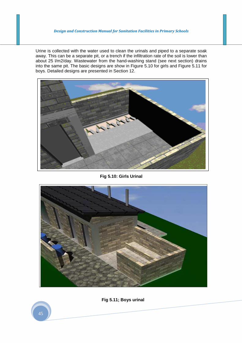
Design and Construction Manual for Sanitation Facilities in Primary Schools
45
Urine is collected with the water used to clean the urinals and piped to a separate soak away. This can be a separate pit, or a trench if the infiltration rate of the soil is lower than about 25 l/m2/day. Wastewater from the hand-washing stand (see next section) drains into the same pit. The basic designs are show in Figure 5.10 for girls and Figure 5.11 for boys. Detailed designs are presented in Section 12.
Fig 5.10: Girls Urinal
Fig 5.11; Boys urinal

Design and Construction Manual for Sanitation Facilities in Primary Schools
46
B l o c k w o r kT r e n c h
S t a n d
P l a s t e r t h e W a l l
a b o u t 0 . 5 m
F a l l
F a l l
1 . 6 m
2 . 5 m
1 . 8 m
U r i n a l T r e n c h
f o r m e d i n c e m e n t
m o r t a r w i t h 1 5 0 m m p i p e
i m p r e s s i o n f a l l i n g t o 2i n c h d r a i na t c o r n e r
U r i n a l D r a i n p i p e
C H B W a l l
h = 1 . 6 m
D r a i n p i p e
Fig 5.12 Sectional view of the urinal for boys
5.5 Hand Washing Facilities
5.5.1 The Basics
After using the toilet or urinal, students should wash their hands to avoid the possibility of getting sick (or making others sick) by faecal – oral contamination. Global lessons learnt and best practice shows that it is absolutely critical to provide hand-washing facilities – water and soap – at the toilet itself. Furthermore, separate and relatively private facilities are needed by adult girls, who may have to use these facilities to wash sanitary cloths if they happen to be having a period (menstruating).
Box 8: Appropriate hand washing facilities 1. Location: The hand washing facility should be located very close to the latrine as
shown in figure 19 above so that children see it in front and outright as they leave. 2. Standard Dimensions: A concrete structure with varying heights is constructed to
keep plastic barrels for carrying water for hand washing. The dimensions vary to suite to the heights of school children. For small children the height of hand washing facility will be 50 cm height while for older children between age 9 and 15 years will use a 70 cm height of hand washing facility.
3. Materials: A plastic [barrel] container with taps installed on it is used. Soap or ash is
also kept as hand washing agents and hygienic materials. 4. Access: Hand washing facilities are located within one and half meters distance
from the latrine and it is near and readily available and accessible for school children using the latrines.
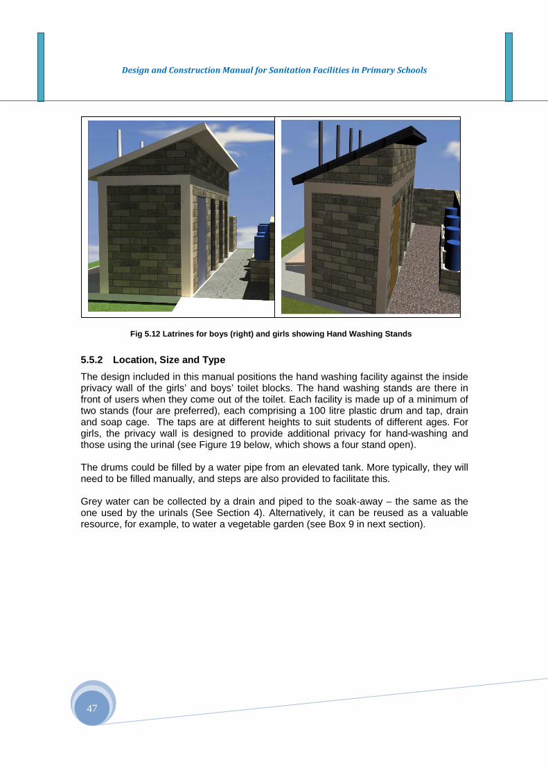
Design and Construction Manual for Sanitation Facilities in Primary Schools
47
5.5.2 Location, Size and Type
The design included in this manual positions the hand washing facility against the inside privacy wall of the girls’ and boys’ toilet blocks. The hand washing stands are there in front of users when they come out of the toilet. Each facility is made up of a minimum of two stands (four are preferred), each comprising a 100 litre plastic drum and tap, drain and soap cage. The taps are at different heights to suit students of different ages. For girls, the privacy wall is designed to provide additional privacy for hand-washing and those using the urinal (see Figure 19 below, which shows a four stand open). The drums could be filled by a water pipe from an elevated tank. More typically, they will need to be filled manually, and steps are also provided to facilitate this. Grey water can be collected by a drain and piped to the soak-away – the same as the one used by the urinals (See Section 4). Alternatively, it can be reused as a valuable resource, for example, to water a vegetable garden (see Box 9 in next section).
Fig 5.12 Latrines for boys (right) and girls showin g Hand Washing Stands

Design and Construction Manual for Sanitation Facilities in Primary Schools
48
SECTION VI: WASTE WATER MANAGEMENT
6.0 Concept The concept of waste water management has been mentioned in the preceding sections and here this important subject receives the attention it deserves. Source of waste occur from excess water from water supply source, drinking water fountains and hand washing facilities at the toilet. If these waste waters are not properly managed, excess water will pond at those waste water sources, stagnant water breed and attract flies and mosquitoes that carry disease. Whilst disposing of waste water efficiently and safely is important, we are also wasting a valuable resource. So, before deciding on how to dispose of waste water, one should first consider if and how it could be reused more productively (Box 4). 6.1 Waste Water or Grey Water is a Valuable Resourc e
Box 6.1: Waste Water, Grey Water, or a Valuable Res ource? Waste water or ‘black water’ refers to water discharged from toilets and urinals. This may contain very high levels of pathogens – and it smells pretty bad as well. Grey water is untreated waste water that has not come into contact with high concentrations of faecal contaminants. In this case, grey water refers to water from hand washing stands, which may be slightly, but not highly contaminated. Management of waste water and grey water is very important. If left to pool on the ground, it may present a health risk – not least by providing mosquitoes with a breeding ground, or attracting domestic animals into the school compound. Water combines with soil to make mud, which may be fun for some – but this can also put off users from entering the toilet or washing their hands. Infiltration of water back into the ground is may work in terms of reducing the health risk. But it is also wasting a valuable resource. If properly handled, grey water can be reused to for cleaning toilets and urinals, or for watering trees and plants - which can be sold by the school to augment its budget. Waste water can also be used in this way, although it needs more careful handling. The concept of grey water reuse and recycling will be described in more detail in a second volume of the School WASH Guideline. This will also include the use of urine as an incredibly potent fertilizer, a broader range of composting toilets. Wait out for details.
6.2 Dispose of or Reuse Waste Water Assuming the decision is made to dispose of waste water rather than reuse it, the following information must be considered.
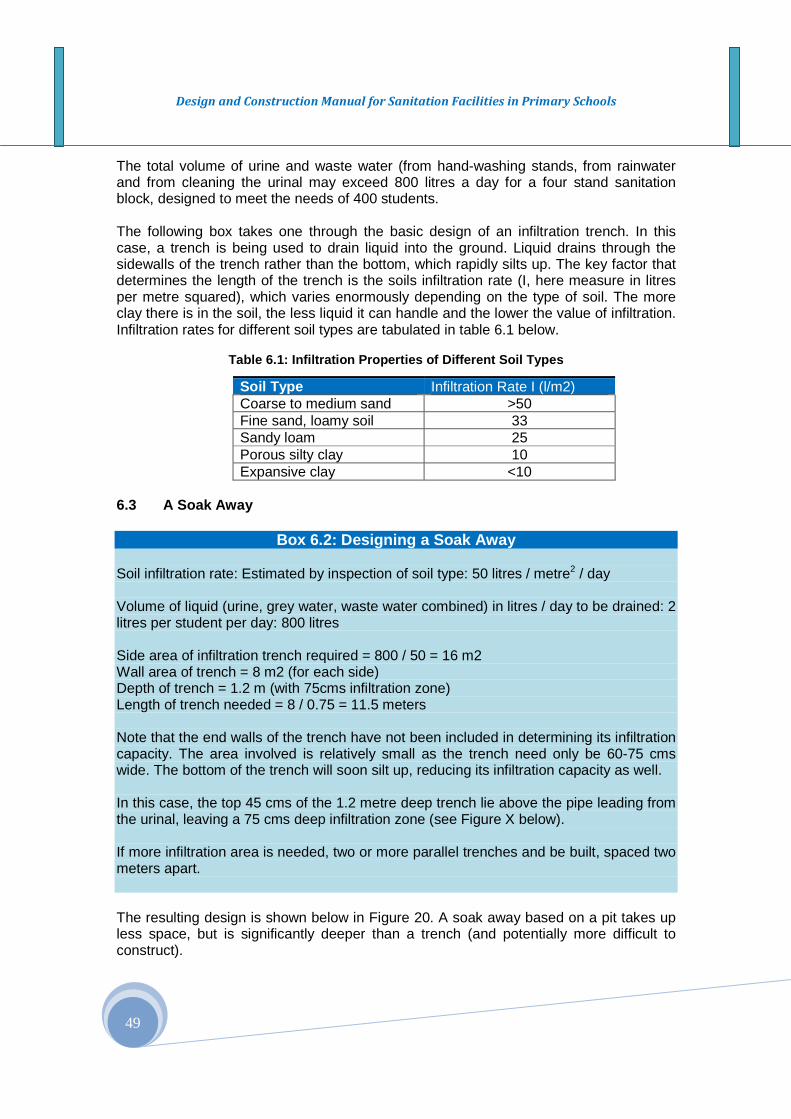
Design and Construction Manual for Sanitation Facilities in Primary Schools
49
The total volume of urine and waste water (from hand-washing stands, from rainwater and from cleaning the urinal may exceed 800 litres a day for a four stand sanitation block, designed to meet the needs of 400 students. The following box takes one through the basic design of an infiltration trench. In this case, a trench is being used to drain liquid into the ground. Liquid drains through the sidewalls of the trench rather than the bottom, which rapidly silts up. The key factor that determines the length of the trench is the soils infiltration rate (I, here measure in litres per metre squared), which varies enormously depending on the type of soil. The more clay there is in the soil, the less liquid it can handle and the lower the value of infiltration. Infiltration rates for different soil types are tabulated in table 6.1 below.
Table 6.1: Infiltration Properties of Different Soi l Types
Soil Type Infiltration Rate I (l/m2) Coarse to medium sand >50 Fine sand, loamy soil 33 Sandy loam 25 Porous silty clay 10 Expansive clay <10
6.3 A Soak Away
Box 6.2: Designing a Soak Away Soil infiltration rate: Estimated by inspection of soil type: 50 litres / metre2 / day Volume of liquid (urine, grey water, waste water combined) in litres / day to be drained: 2 litres per student per day: 800 litres Side area of infiltration trench required = 800 / 50 = 16 m2 Wall area of trench = 8 m2 (for each side) Depth of trench = 1.2 m (with 75cms infiltration zone) Length of trench needed = 8 / 0.75 = 11.5 meters Note that the end walls of the trench have not been included in determining its infiltration capacity. The area involved is relatively small as the trench need only be 60-75 cms wide. The bottom of the trench will soon silt up, reducing its infiltration capacity as well. In this case, the top 45 cms of the 1.2 metre deep trench lie above the pipe leading from the urinal, leaving a 75 cms deep infiltration zone (see Figure X below). If more infiltration area is needed, two or more parallel trenches and be built, spaced two meters apart. The resulting design is shown below in Figure 20. A soak away based on a pit takes up less space, but is significantly deeper than a trench (and potentially more difficult to construct).

Design and Construction Manual for Sanitation Facilities in Primary Schools
50
Using the same design parameters, a circular pit 1.2 meters in diameter would need to be dug to a depth of 4.7 meters to provide an infiltration area of 16 meters2, allowing for the same 45 cm deep freeboard. In practice, two pits each 2.4 meters deep may be easier to excavate.
Figure 6.1: Soak away
Polythlene
membrane
Drain pipe PVC
80mmØ Drilled or
slotted within
trench, on 5%
slope (fall)
Ground level
h
wL
30cm
Side area for
infiltration= 2xlxh

Design and Construction Manual for Sanitation Facilities in Primary Schools
51
SECTION VII: GREEN TECHNOLOGIES FOR WATER PUMPING IN SCHOOLS
7.1 Introduction Climate change is no longer a distant threat to Ethiopia. World wide it has now become daily news and arguably the greatest threat and challenge of our times. For the last five decades, Ethiopia has experienced devastating environmental, social and economic impacts of climate change such as drought, water and power shortages, crop failure and severe food shortages and recently flooding. School children need to learn and understand more about climate change, what causes climate change, and how to cope with its impacts and adaptation and mitigation measures to take against the eminent threat of climate change. Recognizing the enormous challenge of climate change, Ethiopia has prepared a green technology development strategy up to 2050, and the strategy has been presented and endorsed by a global climate change panel in Durban, South Africa in 2011. It is almost a one generation strategic plan which outlines and promotes on the use of Renewable Energy Technology (RET), as alternative power sources with no carbon emission and little damage to the environment. School children have a role to play in the implementation of this strategic plan since they are the future generation that are responsible and most affected by the ongoing and upcoming climate change and its impacts. They are also agents of change for propelling climate change adaption and implementation of the strategy within their own communities. What are the available green technologies that schools can demonstrate to school children while receiving services and at the same time adapting to the eminent climate change of the future? There are some schools that use diesel pumps for pumping deep well water, and the continued use of diesel in the future is increasingly becoming a concern because of its high carbon emission, the fuel it uses is imported and increasingly becoming expensive, less available and accessible in most remote areas where it is badly needed. The ever increasing cost of fuel and the difficulty in securing a sustainable supply of fuel, oil and maintenance services for diesel power made it difficult to rely on. There are enormous evidences that support water facilities that use diesel power are less sustainable. Solar and wind pumps are receiving increasing attention in using them for water pumping in Ethiopia. To supply water for many of the schools with populations in the range between 800 and 1500, designed water supply system particularly motorized shallow and deep well sources require power strong enough to pump water to a suitable storage location uphill from where gravity flow can provide a relatively cheaper water supply services. Renewable energy sources such as solar (Photo voltaic, PV) and wind pumps are now a day important source of energy for water pumping. They are environmentally friendly and cost effective over a long term basis. The following section of the report presents brief introduction on such renewable technology options. For more detail designs and construction, an experienced hydraulic, mechanical and electrical engineers may have to be consulted. References materials are available in several books and websites.

Design and Construction Manual for Sanitation Facilities in Primary Schools
52
7.2 Solar and wind pumps for water pumping The Solar pump system components include the panels, support structure, electronic parts for regulation, cables, pipes and the pump itself. The pump is submersible type and it should be designed and installed according to local situations. Solar radiation data are required for design of the solar (PV pumping) system. Meteorological data on sunshine hours and irradiance are needed for designing photo voltaic (PV) system as a source of power for running submersible pumps. In areas where local meteorological data are not available for use, NASA data could be used using GPS reading for the site.
Figure 7.1 A PV Module for water pumping
7.3 Windmills for Water Pumping A wind pump (windmill) for water pumping consists of a rotor, power transmission to a pump, safety system and a tower (see figure 7.2). Rotor: - The rotor is the essential part of windmill, a prime mover for producing both the mechanical and electrical power. It converts the power of the wind into useful mechanical shaft power. The number of blades can be 4, 6, 8, or 18, mostly supported by spokes only. These rotors operate at higher tip speeds. The rotor is fixed to a steel shaft by means of a hub plate. The shaft is supported by sleeve bearings (receiving oil from the gear oil bath), or by roller bearings (lubricated by grease or by oil). Rotors of water pumping windmills range from 1.5 to 8 m diameter. Power Transmission: - An essential part of a windmill transmission is some kind of eccentric that transforms the rotating movement of the rotor into a reciprocating movement of the pump rod. Water Pump:- The majority of water pumping windmills are equipped with single-acting piston pumps. When the piston moves down, the foot valve closes and water passes through the open piston valve. On the upward stroke the valve in the piston closes, the foot valve opens, and water is pumped to a desired elevation or elevated site where the storage facility is located. Water from the storage tank flows by gravity to the drinking fountain, toilet, hand washing facilities and water supply stands, etc.
Figure 7.2. Components of Wind Pump: 1-blade (rotor), 2 – Tower, 3. Rod (transmission), 4. Supply pipe, 5 – pump, 6 - Tank

Design and Construction Manual for Sanitation Facilities in Primary Schools
53
SECTION VIII: MANAGEMENT AND SUSTAINABILITY OF SCHOOL WASH FACILITIES
8.1 Introduction
As water supply and sanitation facilities are an essential part of the schools, their operation and maintenance should be included in the management plan. But it is often overlooked first at the planning stage, and secondly this oversight has often led to serious problems, both during the execution phase and during the operation and maintenance phase. In particular, the management of a system after its inauguration does not always receive due attention and it is in this area that the concept of sustainability comes under the greatest pressure. Assumptions made and activities undertaken during the planning phase must be examined for long-term implications, and measures must be taken to ensure that the sustainability of the school WASH facilities and the system they constitute is not compromised. Cleanliness in the area of the water and sanitary facilities in school is an important factor in the management and overall introduction of new and improved facilities in schools. If the surrounding area is not kept clean and free of animals, debris, waste and stagnant water, the water and sanitation facilities could have the very undesirable effect of providing an ideal site for breeding vectors and transmission of disease. In this respect, the ability of the school community to manage the system and ensure regular cleaning of the water and sanitation facilities is vital. However little emphasis and attention is given in keep it clean for use, upkeep, maintenance and management of sanitation facilities.
Figure 8.1 Examples of filthy sanitary facilities The photograph above shows a typical situation in many schools which could contribute to the spread of disease or illness among school children. Many of the latrines in schools are poorly managed and hence small children preferred open defecation in areas outside of existing latrines and in the nearby bushes.
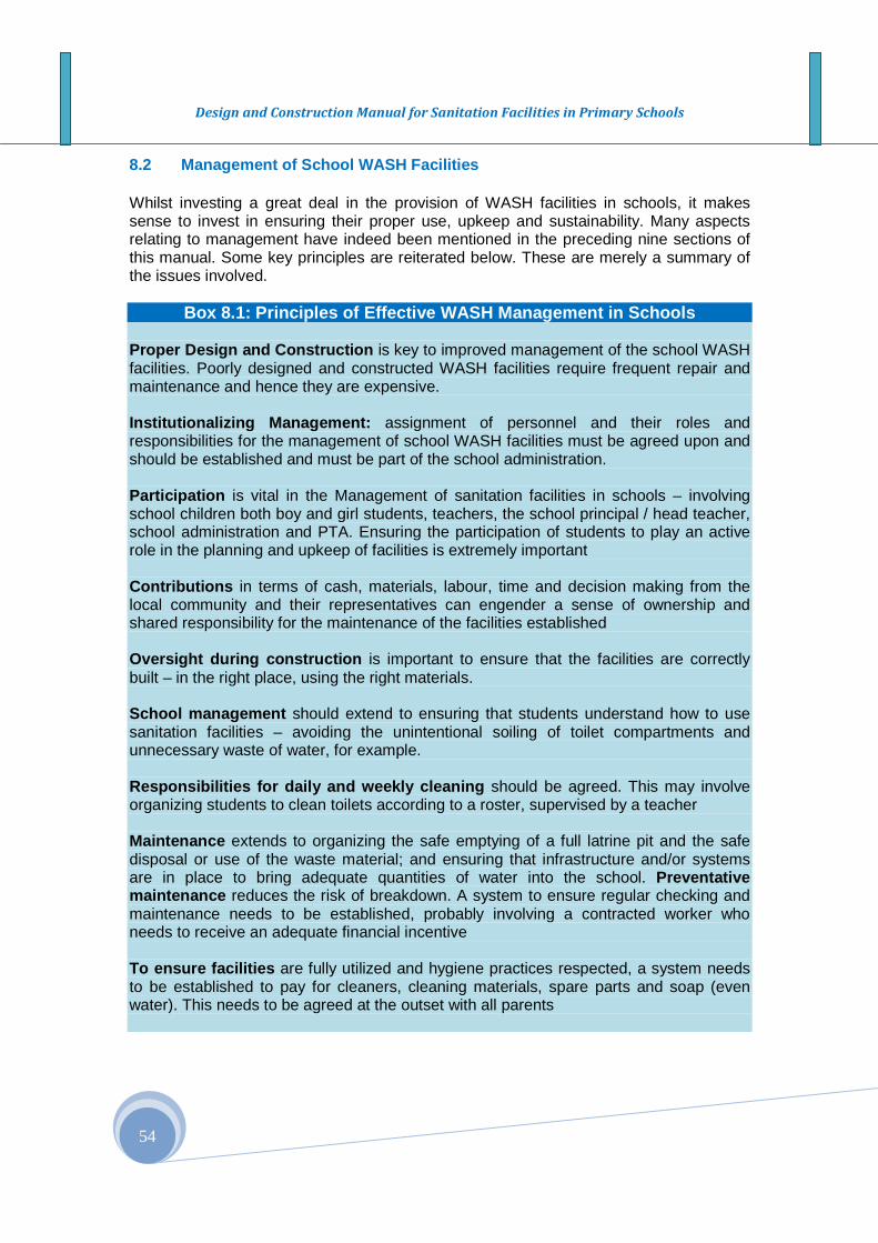
Design and Construction Manual for Sanitation Facilities in Primary Schools
54
8.2 Management of School WASH Facilities Whilst investing a great deal in the provision of WASH facilities in schools, it makes sense to invest in ensuring their proper use, upkeep and sustainability. Many aspects relating to management have indeed been mentioned in the preceding nine sections of this manual. Some key principles are reiterated below. These are merely a summary of the issues involved.
Box 8.1: Principles of Effective WASH Management in Schools Proper Design and Construction is key to improved management of the school WASH facilities. Poorly designed and constructed WASH facilities require frequent repair and maintenance and hence they are expensive. Institutionalizing Management: assignment of personnel and their roles and responsibilities for the management of school WASH facilities must be agreed upon and should be established and must be part of the school administration. Participation is vital in the Management of sanitation facilities in schools – involving school children both boy and girl students, teachers, the school principal / head teacher, school administration and PTA. Ensuring the participation of students to play an active role in the planning and upkeep of facilities is extremely important Contributions in terms of cash, materials, labour, time and decision making from the local community and their representatives can engender a sense of ownership and shared responsibility for the maintenance of the facilities established Oversight during construction is important to ensure that the facilities are correctly built – in the right place, using the right materials. School management should extend to ensuring that students understand how to use sanitation facilities – avoiding the unintentional soiling of toilet compartments and unnecessary waste of water, for example. Responsibilities for daily and weekly cleaning should be agreed. This may involve organizing students to clean toilets according to a roster, supervised by a teacher Maintenance extends to organizing the safe emptying of a full latrine pit and the safe disposal or use of the waste material; and ensuring that infrastructure and/or systems are in place to bring adequate quantities of water into the school. Preventative maintenance reduces the risk of breakdown. A system to ensure regular checking and maintenance needs to be established, probably involving a contracted worker who needs to receive an adequate financial incentive To ensure facilities are fully utilized and hygiene practices respected, a system needs to be established to pay for cleaners, cleaning materials, spare parts and soap (even water). This needs to be agreed at the outset with all parents

Design and Construction Manual for Sanitation Facilities in Primary Schools
55
8.2.1 Technology choice, operation and maintenance The provision of uninterrupted water supply, and sustained and adequate sanitation services are key requirements for a healthy education program in schools. It is important to note that such requirements are taken account during the design and construction phases. As far as possible facilities selected should be durable, easy to operate and repair and maintain without specialist skills. Hence technology selection should take account of local capacities for maintenance and repair. A regular cleaning and maintenance service to the water and sanitation facilities provide the desired healthy environment for schools. Badly maintained water supply and sanitation facilities often cause an even bigger health risk for school children. Stagnant water around tap stands and in blocked drainage channels attracts rodents and it forms a breeding place for mosquitoes and other disease causing vectors. Water supply sources, water lifting devices and power systems and taps may require regular services using local capacities to ensure uninterrupted and long term service to schools. Therefore, there is a strong need for a regular servicing of the different elements in the water supply and sanitation facilities in schools. Drinking fountains, taps, toilets rooms and urinals need to be regularly cleaned with water. If there is power source used for water pumping, it should as well be serviced regularly; malfunctioning parts should be replaced, oil and greasing of parts need to be done on a regular basis before a major breakdown occurs. Responsibilities for operation and maintenance should be clearly defined and appropriate skills provided. 8.2.2 Monitoring School WASH facilities Monitoring is a key to ensure the proper and continuous functioning of water and sanitation facilities in schools. Table 8.1 below presents the monitoring requirements of WASH facilities in schools.
Table 8.1 Monitoring Requirements Activities Frequency Manpower
assignments Regular cleaning of the latrines, urinals, hand washing facilities and drinking fountains
Daily Cleaners or school children (above 9 yrs of age) with guidance and close supervision by teachers.
Inspect the water supply system and sanitary facilities (latrine, urinal and hand washing) for any malfunction, crack, damage, etc. that may occur during use.
Daily Cleaners/ Administrator, students/Teachers
Every six months
Professional Engineer/ contractor
Repair and maintain water supply system, latrine slab, seat, vent pipe and fly screen or any part of the latrine superstructure
Immediately as reported
Hired contractor, trained school community member, Trained teachers & students
When twine pit is full, open the second hole and switch to other pit
When full Local mason
Empty pit (for composting type) One year after the pit is sealed
Contracted or hired labor or local municipal service
Design and Construction Manual for Sanitation Facilities in Primary Schools
56
Every month the floor of the latrine slabs has to be checked for cracks and the vent pipe and fly screen are properly functioning. Fly screen must be inspected and when needed replaced to ensure their effective use. Rainwater should drain away from the latrines. For deep and conventional pit and when their content of the pits reach the level of 0.5 m below the slab, a new pit has to be dug and the old pit should be abandoned. In composting type, the pits are emptied as per the scheduled period. Monitoring require regular reports indicated what has been observed and actions taken on the facilities, and these reports have to be shared among the school administration, PTA and partners, woreda sector offices on a regular basis. 8.2.3 Roles and Responsibilities of the stakeholder s in the management of
school WASH facilities School Children
� Participate in the design process, � They should comply with procedures for use and care, � Observe appropriate hygiene measures and practices in school,
Teachers � Monitor the state and use of facilities, � Organize the care and maintenance of facilities, � Motivate school children to adopt appropriate behavioral changes, � Provide hygiene education
School Directors or head teachers � Organize different occasions for water, sanitation and hygiene at school level; for
instance a hand washing day, environmental day to clean the school, etc. � Create enabling environment for teachers and staffs to achieve and maintain
certain targets set for each school year Parent Teachers Associations (PTAs)
� Monitor regularly the conditions of the facilities and conduct discussion with school administrations
� Advocate locally for improvement in the management and financing of the facilities,
� Support the maintenance of school facilities School Children Families
� Encourage children to comply with procedures for use and care of WASH facilities in schools and at home,
� Support or participate actively in Parent Teacher Associations, � Contribute to the financing of school WASH facilities and servicing
Sector Offices at woreda level � The sector offices should provide guidance on environmental health aspect,
repair and maintenance, � Staffs should conduct regular monitoring on the conditions of the facilities on a
regular basis, Woreda and Kebele Officials
� Ensure schools are provided with resources such as land, funding and security 8.2.4 Financing School WASH Program Finance is a critical input in the construction, operation and maintenance of water supply and sanitation facilities. Contributions from government, donors, or private individuals or
Design and Construction Manual for Sanitation Facilities in Primary Schools
57
local community are major sources of funding the school WASH facilities. There is a budget set by the government but very small for up-keeping WASH facilities in schools. Schools should develop their own fund raising strategy. One approach could be laying fee (in the range between 1 to 10 Birr per each child during registration, and this could be a significant resource with the existing government budget. To generate more funding, schools may have to engage in schemes for generating their own income such as gardening using the excess water from water supply, or grey water from a hand-washing stand for irrigation. The use of urine collected from urinals could be fertilizer for the production of cash crops, and the proceeds from the sales of products such as grasses (hey), vegetables, etc. could be a source of additional funding. This will have multi pronged benefits to the school and the community: (i) make cash income, (ii) works as a demonstration for school children on modern gardening and crop production, (iii) contribute to access to food security by making additional food available for sale to local communities, and (iv) the funds raised can pay towards the upkeep of the water supply, for buying soap for hand washing facilities, and buying detergents for cleaning latrines, urinals and other WASH facilities in schools. 8.2.5 Participation and Coordination at local level Managing the WASH facilities at local level require the engagement of all the stakeholders and require effective coordination at local level. School administration, school community (teachers and students) and PTA, and the local government and non-governmental organizations (NGOs) operating in the area could participate effectively through improved and effective coordination of relevant stakeholders. The different clubs such as health (sanitation) and environment clubs in schools can play a very positive role in creating awareness about the importance of water, sanitation and hygiene, and they can play active role in the management of school WASH facilities. The school administration and teachers should take the role in coordinating the different efforts with regard to water, sanitation and hygiene at local level. At the national level and regional level, the relevant government and non-governmental agencies such as the MoWE, MoH, MoE and international non governments organizations and multilateral organizations such as the WHO and UNICEF can play major role in promoting the capacity building of school administration to improve water and sanitation services for schools in the country. 8.2.6 Integrated management of WASH facilities There is a need to incorporating and integrating water supply; sanitation and hygiene (WASH) in the management of the School WASH facilities in order to have long term services and create synergy in terms creating the desired impact on child hygiene and behavior. It is also useful in conserving, protecting and managing water for different uses that the school need; gardening, greening school compounds, etc. Another principle in IWRM is the efficient use of water resources. School children should be taught through demonstration and participation that catchment areas serve as principal source to clean water and need to be protected and conserved and the school children should participate and be leaders in the effort to conserve, protect, reclaim and rehabilitate the catchments where water source are developed within their environment. School teachers should be their model in promoting these principles.
Design and Construction Manual for Sanitation Facilities in Primary Schools
58
ANNEXES

Design and Construction Manual for Sanitation Facilities in Primary Schools
59
Annex A: DETAILED DESIGNS FOR WATER SUPPLY

Design and Construction Manual for Sanitation Facilities in Primary Schools
60
Annex A1: Design and Construction of Hand-Dug Wells
Design and Construction Manual for Sanitation Facilities in Primary Schools
Design and Construction Manual for Sanitation Facilities in Primary Schools

Design and Construction Manual for Sanitation Facilities in Primary Schools
63
Annex A2: Design and Construction of Spring Develop ment
Annex A2 Figure 1 Perspective views of spring water protection
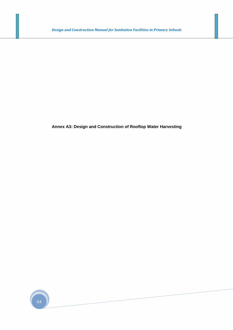
Design and Construction Manual for Sanitation Facilities in Primary Schools
64
Annex A3: Design and Construction of Rooftop Water Harvesting
Design and Construction Manual for Sanitation Facilities in Primary Schools
Figure 2 Rooftop Water Harvesting
Design and Construction Manual for Sanitation Facilities in Primary Schools
66
Annex B: DETAILED DESIGNS FOR VIP LATRINES

Design and Construction Manual for sanitation and hygiene in Primary Schools
United Nations Children Fund – Ethiopia Program April 2012 67
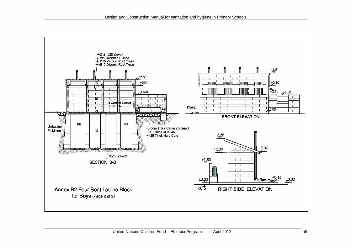
Design and Construction Manual for sanitation and hygiene in Primary Schools
United Nations Children Fund – Ethiopia Program April 2012 68

Design and Construction Manual for sanitation and hygiene in Primary Schools
United Nations Children Fund – Ethiopia Program April 2012 69

Design and Construction Manual for sanitation and hygiene in Primary Schools
United Nations Children Fund – Ethiopia Program April 2012 70
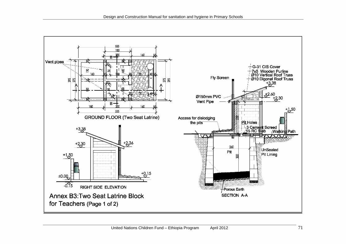
Design and Construction Manual for sanitation and hygiene in Primary Schools
United Nations Children Fund – Ethiopia Program April 2012 71
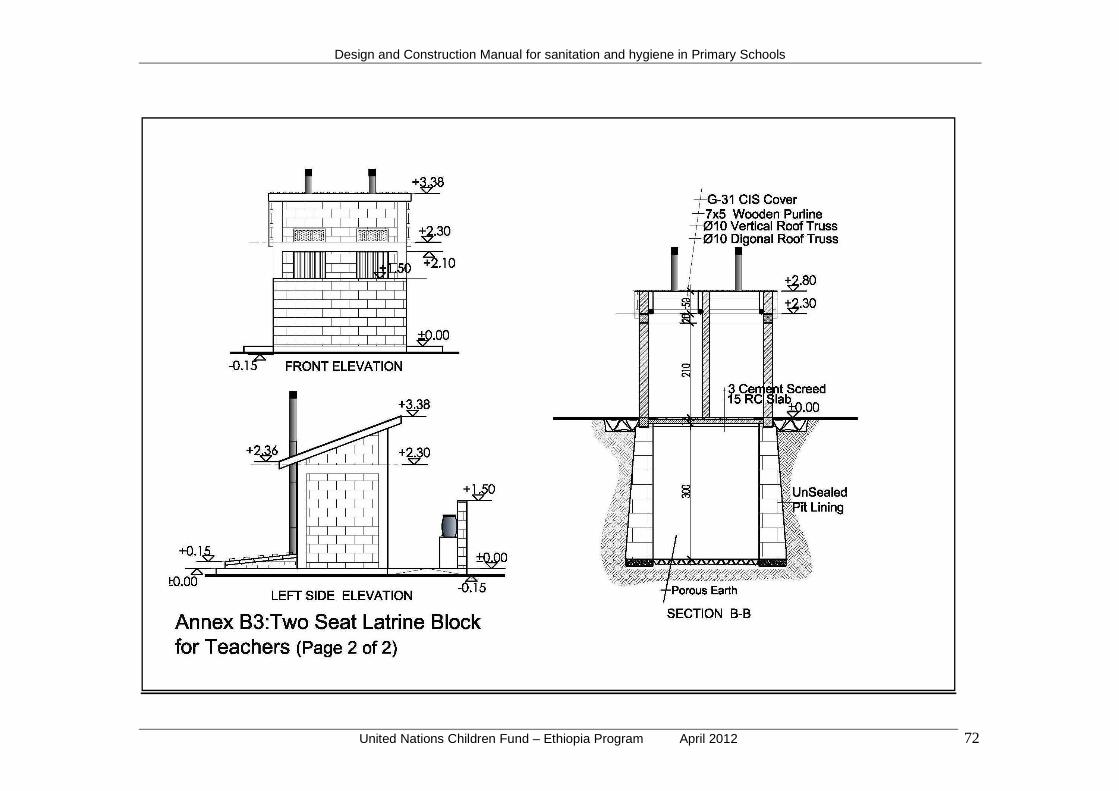
Design and Construction Manual for sanitation and hygiene in Primary Schools
United Nations Children Fund – Ethiopia Program April 2012 72
Design and Construction Manual for sanitation and hygiene in Primary Schools
United Nations Children Fund – Ethiopia Program April 2012 73
ANNEX C: BILL OF QUANTITIES
Annex C1: FOR DESIGNED WATER SUPPLY

Design and Construction Manual for sanitation and hygiene in Primary Schools
United Nations Children Fund – Ethiopia Program April 2012 74
Annex C1: Table 1 Bill of quantities for Spring Development
Item Description Unit Qty Rate Total 1 Mobilization /Demobilization
a Mobilization to site each 1 b Demobilization from site each 1 c Renting equipment each 1
Sub –Total I 2 Spring Eye
a Site clearing m2 25 b Excavation for foundation m3 5 c Concrete work for foundation below masonry work
( when necessary) m3 0.54
d Spring Box masonry work m3 5 e Three coat plastering for the capping structure from
inside. m2 2.84
f Filling the spring box with stones and river gravel m3 5
g Casting concrete on top of the spring eye m2 6
h Pointing the masonry walls of spring capping structure from outside
m2 1.05
i Preparing the manhole with cover and fixing the necessary plumbing works
each 1
j Fencing the spring eye ( 5mx5 m ) and preparing flood protection ditches
each 1
Sub – Total II 3 2 m3 collection chamber
a Site clearing m2 25 b Excavation for foundation m3 4 c Foundation masonry works m3 4 d Hard core filling m3 2,4 e 5 cm thick lean concrete above the hardcore m2 7.36 f Water tight basement, 10 cm thick concrete work m3 0.5
g Construction of collection chamber 1th 50cm thick masonry walls
m3 5
h Applying three coats plastering to the collection chamber from inside
m2 6
i Casting of 12 cm thick reinforced concrete slab to cover the collection chamber
m3 0.6
j Pointing the collection chamber masonry walls from outside
m2 7.08
k Preparing manhole with cover and fixing all plumbing works including the connection pipe from the spring eye.
each 1
l Fencing around the collection chamber (8m X8m). Constructing necessary steps and drainage works
each 1
Sub – Total III
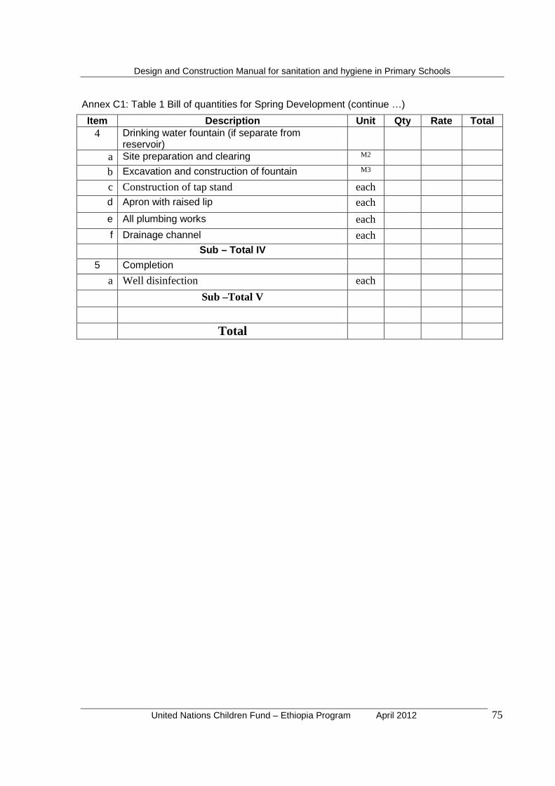
Design and Construction Manual for sanitation and hygiene in Primary Schools
United Nations Children Fund – Ethiopia Program April 2012 75
Annex C1: Table 1 Bill of quantities for Spring Development (continue …)
Item Description Unit Qty Rate Total 4 Drinking water fountain (if separate from
reservoir)
a Site preparation and clearing M2 b Excavation and construction of fountain M3 c Construction of tap stand each d Apron with raised lip each e All plumbing works each f Drainage channel each
Sub – Total I V 5 Completion
a Well disinfection each Sub –Total V
Total
Design and Construction Manual for sanitation and hygiene in Primary Schools
United Nations Children Fund – Ethiopia Program April 2012 76
Annex C1: Table 2 Bill of quantities for a Hand Dug Well
Item
Description
Unit
Qty
Rate
Total
1 Mobilization/Demobilization a To site for well construction each 1 b To site for well deepening each 1 c From site after well construction each 1 d From site after well deepening each 1 e Renting equipment Sub –Total I
2 Setting up / excavation (1.5 meter max. diameter hole) a Site preparation each 1 b Excavation above water table ( 0-4 meters) m 4 c Excavation above water table(4-8 meters) m 4 d Excavation above water table ( 8- 12 meters) m 4 e Excavation above water table( 12- 16 meters) m 4
f Excavation above water table (over 16 meters) m 4 g Excavation below the water table (3 meters) m 3 h Excavation in hard rock (provisional payment) m 5 i Excavation for 2 meter diameter hole m 20 j Deepening of the well additional m 2
Sub – Total
3 Well lining (concrete – in-situ cast or pre-cast) a Well lining above the water table ( 0-4 metres) m 4
b Well lining above the water table (4 – 8 metres) m 4 c Well lining above the water table ( 8 – 12 metres) m 4
d Well lining above the water table (12- 16 metres) m 4
e Well lining above the water table (over 16 metres) m 4
3 Well lining ( masonry)
a Well lining above the water table ( 0- 4 metres) m 4 b Well lining above the water table ( 4- 8 metres) m 4 c Well lining above the water table (8- 12 metres) m 4 d Well lining above the water table ( 12- 16 metres) m 4
Sub – TOTAL III 4 Works below water table
a Caisson lining below the water table ( 3 metres) m 3 b Caisson lining for well deepening (provisional payment
– 2 metres) m 2
c Graded gravel inlet filter each 1 d Concrete base plug each 1 Sub Total Iv
Design and Construction Manual for sanitation and hygiene in Primary Schools
United Nations Children Fund – Ethiopia Program April 2012 77
Annex C1: Table 2 Bill of quantities for a Hand Dug Well (continue …)
Item Description Unit Qty Rate Total 5 Head works
a Head wall each 1
b Well cover slab each 1 c Access hatch cover each 1 d Access hatch cover each 1
e Apron with raised lip each 1 f Drainage channel each 1 g Trough and / or soak away Pit each 1
h Hand pump (Afri dev Installation each 1 i Windlass construction each 1 Sub – Total V
6 Completion a Well disinfection and cleaning each 1 b Construction of fence each 1 c Operation and maintenance training each 1 Sub – Total VI TOTAL

Design and Construction Manual for sanitation and hygiene in Primary Schools
United Nations Children Fund – Ethiopia Program April 2012 78
Annex C2: BILL OF QUANTITIES FOR DESIGNED VIP LATRI NES

Design and Construction Manual for sanitation and hygiene in Primary Schools
United Nations Children Fund – Ethiopia Program April 2012 79
Annex C2: Table 1 - A 2 seat latrine for teachers
Se. No. Description Unit Qty. Unit
Price Total Price
I. Latrine Block – 2 seat latrine block
A. Sub-Structure
1 Excavation & Earth Work
1.1 Clear off the site to remove top soil to an average depth m2 42.47
of 30 cm
1.2 Bulk excavation to reduce level excavation to ordinary soil m3 31.34
not exceeding 1.5m
1.3 Over 1.5m not exceeding 3.0 m m3 29.64
1.4 Back fill under hard core & around masonry with selected m3 4.01
granular borrowed material from out side & well ram
in layers not exceeding 20 cm thick until it attains
a minimum of 95 % proctor density.
1.5 Cart away surplus excavated material & deposit at m3 69.71
a distance not exceeding 1km from the site.
1.6 25cm thick basaltic or equivalent stone hardcore, well rolled, m2 15.81
Consolidated & blinded with crushed stone
Total to summary
2 Concrete Work
2.1 5cm thick lean concrete class C-5, 150 kg cement / m3
concrete, under masonry foundation wall.
a) under masonry m2 14.28
Design and Construction Manual for sanitation and hygiene in Primary Schools
United Nations Children Fund – Ethiopia Program April 2012 80
Annex C2: Table 1 - A 2 seat latrine for teachers
Se. No. Description Unit Qty. Unit
Price Total Price
2.2 Reinforced concrete, C-25, 360 kg cement/m3 of concrete
filled into form work and vibrated around reinforcement
measured separately.
a) in grade beam m3 2.06
2.3 In 15 cm thick RC ground floor slab class C-20 with
minimum cement content of 320 kg/m3 evenly spread m2 17.48
2.4 Provide cut and fix in position sawn zigba formwork
or equivalent.
a) For grade beam m2 14.86
b) For ground slab m2 1.68
c) Support poles of 8mm diameter & 3m length No 144.0
2.5 Steel reinforcement according to drawing cut, bend
& placed in position, unit price shall include cutting,
bending & placing in position & tying wires.
a) Ф 6mm kg 28.73
b) Ф 10mm kg 107.23
c) Ф 12mm kg 84.36
Total to summary
Design and Construction Manual for sanitation and hygiene in Primary Schools
United Nations Children Fund – Ethiopia Program April 2012 81
Annex C2: Table 1 - A 2 seat latrine for teachers (continue…)
Se.
No. Description Unit Qty.
Unit
Price Total Price
3 Masonry Work
3.1 500mm thick trachytic or equivalent stone masonry below m3 24.46
ground level bedded in cement mortar (1:4) in full joints.
Total to summary
3.2 20X20X40cm Solid Concrete Block Pit Partition Wall m2 15.6
"class C" bedded in cement sand mortar 1:3 both side
left for plastering
Total to summary
B. Super-Structure
1 Concrete Work
1.1 Reinforced concrete, C-25, 360 kg cement/m3 of concrete
filled in to form work and vibrated around reinforcement
measured separately.
a) in elevation columns m3 0.37
b) in top tie beam m3 0.36
1.2 Provide cut and fix in position sawn zigba forkwork or
equivalent.
a) to elevation columns m2 7.36
b) to top tie beam m2 5.46
1.3 Steel reinforcement according to drawing cut, bend &
placed in position, unit price shall include cutting, bending
& placing in position.
a) Ф 6mm Kg 15.86
a) Ф12mm Kg 86.31
Total to summary
2 Concrete Block Work Above Grade Walls
2.1 20X20X40cm HCB Wall "class C" bedded in cement m2 19.27
sand mortar 1:3 both side left for plastering
2.2 15X20X40cm HCB Wall "class C" bedded in cement m2 8.11
sand mortar 1:3 both side left for plastering
Total to summary

Design and Construction Manual for sanitation and hygiene in Primary Schools
United Nations Children Fund – Ethiopia Program April 2012 82
Annex C2: Table 1 - A 2 seat latrine for teachers (continue…)
S. No. Description Unit Qty. Unit
Price Total Price
3 Roof Work
3.1 Roof cover in G32 CIS Nailed to 5x7cm battens as proposed by the
Engineer. m2 8.63
3.2 Supply and fix G-32 galvanized sheet metal
gutter and down pipe
a) Gutter 60cm devt. ml 3.8
b) Down pipe 33cm devt ml 2.8
4 Vent Pipe
a) PVC vent pipe ø 110 mm m 12
Total to summary
5 Carpentry Work
All structure truss members shall be in seasoned eucalyptus
wood and painted two coats of anti termite solution and
shall be tight fixed with top tie beam with 6mm diameter plain bar.
4.1 Diameter 8cm eucalyptus upper and lower chord ml 5.94
4.2 Diameter 6cm eucalyptus vertical and diagonal members ml 2.76
4.3 50x70mm zigba roof purlin ml 12.6
Total to summary
6 Metal Work
All metal doors are manufactured from locally produced
LTZ seiko steel profile frames. All works should be cut
and assembled to sizes and shapes of the door schedule
upon submitting workshop drawing by the contractor.
unit price includes cylinder lock or similar, door stoppers
and other necessary accessories for completing the work.
All according to doors schedule and as specified.
6.1 Type D2, size:- 70x210cm No 2
Mesh wire m2 1
Total to summary
7 Plastering and Pointing
6.1 Pointing to all internal and external HCB wall surfaces m2 55.74
with cement sand mortar 1:2
6.2 Apply three coats of plastering to beam & columns surface m2 26.50
6.3 Supply and made an average thickness of 5cm roughened
cement sand screed with 0.1 aggregate mix, price m2 17.92
Includes chiseling of floor.
6.4 Stone riprap foot path in front and around the latrine m2 15.90
Total to summary
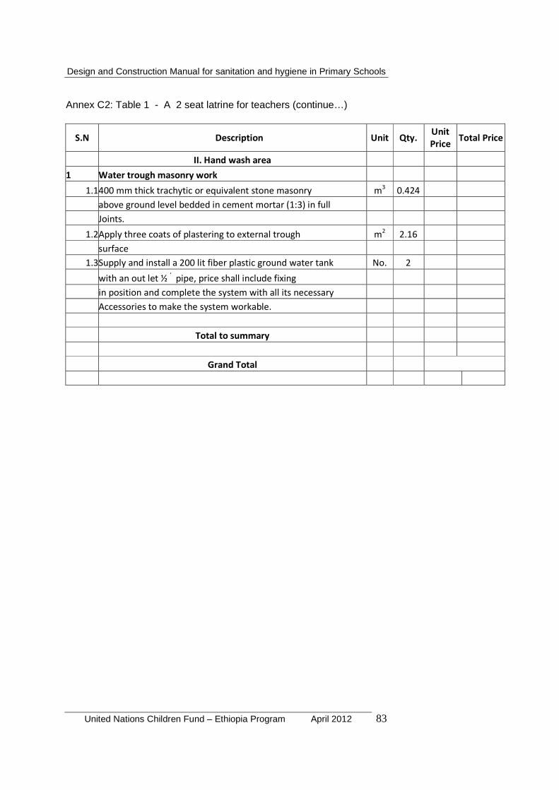
Design and Construction Manual for sanitation and hygiene in Primary Schools
United Nations Children Fund – Ethiopia Program April 2012 83
Annex C2: Table 1 - A 2 seat latrine for teachers (continue…)
S.N Description Unit Qty. Unit
Price Total Price
II. Hand wash area
1 Water trough masonry work
1.1400 mm thick trachytic or equivalent stone masonry m3 0.424
above ground level bedded in cement mortar (1:3) in full
Joints.
1.2Apply three coats of plastering to external trough m2 2.16
surface
1.3Supply and install a 200 lit fiber plastic ground water tank No. 2
with an out let ½ ‘ pipe, price shall include fixing
in position and complete the system with all its necessary
Accessories to make the system workable.
Total to summary
Grand Total
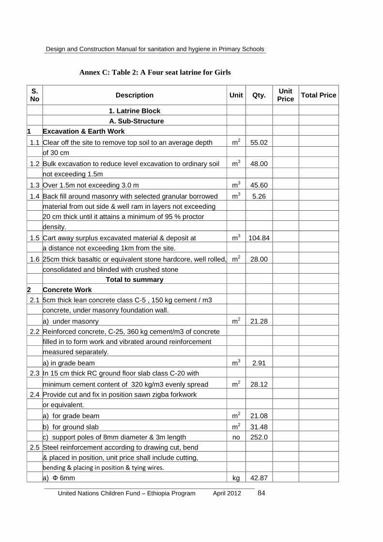
Design and Construction Manual for sanitation and hygiene in Primary Schools
United Nations Children Fund – Ethiopia Program April 2012 84
Annex C: Table 2: A Four seat latrine for Girls
S. No Description Unit Qty. Unit
Price Total Price
1. Latrine Block
A. Sub-Structure
1 Excavation & Earth Work
1.1 Clear off the site to remove top soil to an average depth m2 55.02
of 30 cm
1.2 Bulk excavation to reduce level excavation to ordinary soil m3 48.00
not exceeding 1.5m
1.3 Over 1.5m not exceeding 3.0 m m3 45.60
1.4 Back fill around masonry with selected granular borrowed m3 5.26
material from out side & well ram in layers not exceeding
20 cm thick until it attains a minimum of 95 % proctor
density.
1.5 Cart away surplus excavated material & deposit at m3 104.84
a distance not exceeding 1km from the site.
1.6 25cm thick basaltic or equivalent stone hardcore, well rolled, m2 28.00
consolidated and blinded with crushed stone
Total to summary 2 Concrete Work
2.1 5cm thick lean concrete class C-5 , 150 kg cement / m3
concrete, under masonry foundation wall.
a) under masonry m2 21.28
2.2 Reinforced concrete, C-25, 360 kg cement/m3 of concrete
filled in to form work and vibrated around reinforcement
measured separately.
a) in grade beam m3 2.91
2.3 In 15 cm thick RC ground floor slab class C-20 with
minimum cement content of 320 kg/m3 evenly spread m2 28.12
2.4 Provide cut and fix in position sawn zigba forkwork
or equivalent.
a) for grade beam m2 21.08
b) for ground slab m2 31.48
c) support poles of 8mm diameter & 3m length no 252.0
2.5 Steel reinforcement according to drawing cut, bend
& placed in position, unit price shall include cutting,
bending & placing in position & tying wires.
a) Ф 6mm kg 42.87

Design and Construction Manual for sanitation and hygiene in Primary Schools
United Nations Children Fund – Ethiopia Program April 2012 85
Annex C: Table 2: A Four seat latrine for Girls (continue…)
S.n Description Unit Qty. Unit Price
Total Price
3 Masonry Work
3.1 500mm thick trachytic or equivalent stone masonry below m3 33.59
ground level bedded without cement mortar.
3.2 The top 50 cm masonry bedded with cement mortar(1:3) m3 5
Total to summary
3.2 20X20X40cm Solid Concrete Block Pit Partition Wall m2 31.2
"class C" bedded in cement sand mortar 1:3 both side left for plastering Total to summary
B. Super-Structure
1 Concrete Work
1.1 Reinforced concrete, C-25, 360 kg cement/m3 of concrete
filled in to form work and vibrated around reinforcement
measured separately.
a) In elevation columns m3 0.37
b) In top tie beam m3 0.46
1.2 Provide cut and fix in position sawn zigba formwork or
equivalent.
a) to elevation columns m2 14.72
b) to top tie beam m2 12.08
1.3 Steel reinforcement according to drawing cut, bend &
placed in position, unit price shall include cutting, bending
& placing in position.
a) Ф 6mm Kg 21.26
b) Ф12mm Kg 107.63
Total to summary 2 Concrete Block Work Above Grade Walls
2.1 20X20X40cm HCB Wall "class B" bedded in cement m2 30.70
sand mortar 1:3 both side left for plastering
2.2 15X20X40cm HCB Wall "class B" bedded in cement m2 19.97
sand mortar 1:3 both side left for plastering
Total to summary

Design and Construction Manual for sanitation and hygiene in Primary Schools
United Nations Children Fund – Ethiopia Program April 2012 86
Annex C: Table 2: A Four seat latrine for Girls (continue …)
Item No Description Unit Qty. Unit Price
Total Price
3 Roof Work
3.1 Roof cover in G32 CIS Nailed to 5x7cm battens as m2 16.85
proposed by the Engineer.
3.2 Supply and fix G-32 galvanized sheet metal gutter and
down pipe
a) Gutter 60cm developed . ml 6.8
b) Down pipe 33cm developed ml 2.8 4 Vent Pipe
a) PVC vent pipe ø 110 mm m 20.0
Total to summary 5 Carpentry Work
All structure truss members shall be in seasoned eucalyptus
wood and painted two coats of anti termite solution and
shall be tight fixed with top tie beam with 6mm diameter
plain bar.
5.1 Diameter 8cm eucalyptus upper and lower chord ml 17.82
5.2 Diameter 6cm eucalyptus vertical and diagonal members ml 8.28
5.3 50x70mm zigba roof purloin ml 24.6
Total to summary 6 Metal Work (Door)
All metal doors are manufactured from locally produced
LTZ seiko steel profile frames. All works should be cut
and assembled to sizes and shapes of the door schedule
upon submitting workshop drawing by the contractor.
Unit price includes cylinder lock or similar, door stoppers
and other necessary accessories for completing the work.
All according to doors schedule and as specified.
6.1 Type D1, size:- 90x210cm No 1
6.2 Type D2, size:- 70x210cm No 3
6.3 Door Lock No 4
Total to summary 7 Plastering and Pointing
7.1 Pointing to all Internal and External HCB wall surfaces m2 93.37
with cement sand mortar 1:2
7.2 Apply three coats of plastering to beam & columns surface m2 38.14
7.3 Average thickness of 5cm roughened cement sand screed
with 0.1 aggregate mix, price includes chiseling of floor m2 34.48

Design and Construction Manual for sanitation and hygiene in Primary Schools
United Nations Children Fund – Ethiopia Program April 2012 87
Annex C: Table 2: A Four seat latrine for Girls (continue…)
S.n Description Unit Qty. Unit Price
Total Price
7.4 Stone riprap foot path in front and around the latrine m2 24.86
Total to summary
II. Urinal Block
A. Sub -Structure
1 Excavation & Earth Work
1.1 Clear off the site to remove top soil to an average depth m2 10.13
of 30 cm
1.2 Bulk excavation to reduce level excavation to ordinary soil m3 4.70
not exceeding 1.5m
1.3 Back fill under hard core & around masonry with selected m3 2.51
granular borrowed material from out side & well ram in layers
not exceeding 20 cm thick until it attains a minimum of
95 % proctor density.
1.4 Cart away surplus excavated material and deposit at a distance m3 5.23
not exceeding 1km from the site.
1.5 25cm thick basaltic or equivalent stone hardcore, well rolled, m2 8.38
consolidated & blinded with crushed stone
Total to summary 2 Concrete Work
2.1 5cm thick lean concrete class C-5 , 150 kg cement / m3 m2 4.38
concrete, under masonry foundation wall.
a) under masonry
2.2 Reinforced concrete, C-25, 360 kg cement/m3 of concrete
filled in to form work and vibrated around reinforcement
measured separately.
a) For grade beam m3 0.35
2.3 Provide cut and fix in position sawn zigba formwork
or equivalent.
a) For grade beam m2 3.50
2.4 Steel reinforcement according to drawing cut, bend
& placed in position, unit price shall include cutting,
bending & placing in position & tying wires.
Ф 6mm kg 7.42
Ф 12mm kg 33.03
Total to summary
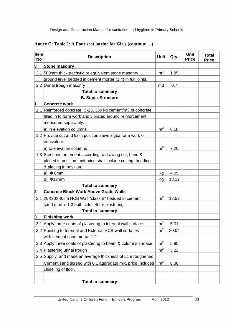
Design and Construction Manual for sanitation and hygiene in Primary Schools
United Nations Children Fund – Ethiopia Program April 2012 88
Annex C: Table 2: A Four seat latrine for Girls (continue …)
Item No Description Unit Qty. Unit
Price Total Price
3 Stone masonry
3.1 500mm thick trachytic or equivalent stone masonry m3 1.85
ground level bedded in cement mortar (1:4) in full joints.
3.2 Urinal trough masonry m3 0.7
Total to summary B. Super-Structure
1 Concrete work
1.1 Reinforced concrete, C-25, 360 kg cement/m3 of concrete
filled in to form work and vibrated around reinforcement
measured separately.
a) in elevation columns m3 0.18
1.2 Provide cut and fix in position sawn zigba form work or
equivalent.
a) to elevation columns m2 7.20
1.3 Steel reinforcement according to drawing cut, bend &
placed in position, unit price shall include cutting, bending
& placing in position.
a) Ф 6mm Kg 4.05
b) Ф12mm Kg 18.12
Total to summary 2 Concrete Block Work Above Grade Walls
2.1 20X20X40cm HCB Wall "class B" bedded in cement m2 12.53
sand mortar 1:3 both side left for plastering
Total to summary 3 Finishing work
3.1 Apply three coats of plastering to internal wall surface m2 5.01
3.2 Pointing to Internal and External HCB wall surfaces m2 20.04
with cement sand mortar 1:2
3.3 Apply three coats of plastering to beam & columns surface m2 5.90
3.4 Plastering urinal trough m2 3.22
3.5 Supply and made an average thickness of 5cm roughened
Cement sand screed with 0.1 aggregate mix, price Includes m2 8.38
chiseling of floor.
Total to summary

Design and Construction Manual for sanitation and hygiene in Primary Schools
United Nations Children Fund – Ethiopia Program April 2012 89
Annex C: Table 2: A Four seat latrine for Girls (continue …)
Item No Description Unit Qty. Unit
Price Total Price 4 Painting
4.1 Apply three coats of approved type oil paint to internal m2 8.35
Plastered wall surface H=1000
Total to summary
III. Hand Washing Facility
1 Water trough masonry work
1.1400 mm thick trachytic or equivalent stone masonry m3 0.992
above ground level bedded in cement mortar (1:3) in full
Joints.
1.2Apply three coats of plastering to External trough m2 5.68
surface
1.3Supply & install a 25 lit fiber plastic ground water tank No. 4
with an out let ½ ‘ pipe price shall include fixing
in position and complete the system with all its necessary
Accessories to make the system workable.
Total to summary
Grand Total
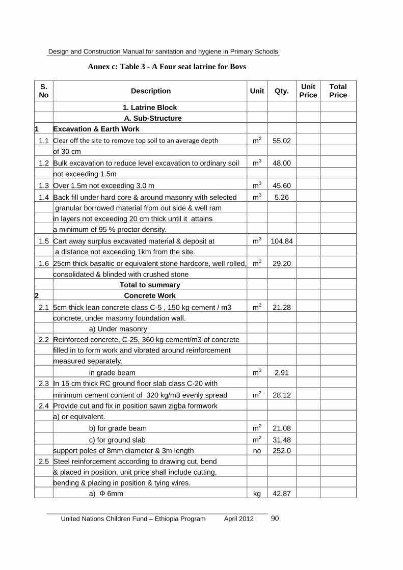
Design and Construction Manual for sanitation and hygiene in Primary Schools
United Nations Children Fund – Ethiopia Program April 2012 90
S. No Description Unit Qty. Unit
Price Total Price
1. Latrine Block
A. Sub-Structure
1 Excavation & Earth Work
1.1 Clear off the site to remove top soil to an average depth m2 55.02
of 30 cm
1.2 Bulk excavation to reduce level excavation to ordinary soil m3 48.00
not exceeding 1.5m
1.3 Over 1.5m not exceeding 3.0 m m3 45.60
1.4 Back fill under hard core & around masonry with selected m3 5.26
granular borrowed material from out side & well ram
in layers not exceeding 20 cm thick until it attains
a minimum of 95 % proctor density.
1.5 Cart away surplus excavated material & deposit at m3 104.84
a distance not exceeding 1km from the site.
1.6 25cm thick basaltic or equivalent stone hardcore, well rolled, m2 29.20
consolidated & blinded with crushed stone
Total to summary
2 Concrete Work
2.1 5cm thick lean concrete class C-5 , 150 kg cement / m3 m2 21.28
concrete, under masonry foundation wall.
a) Under masonry
2.2 Reinforced concrete, C-25, 360 kg cement/m3 of concrete
filled in to form work and vibrated around reinforcement
measured separately.
in grade beam m3 2.91
2.3 In 15 cm thick RC ground floor slab class C-20 with
minimum cement content of 320 kg/m3 evenly spread m2 28.12
2.4 Provide cut and fix in position sawn zigba formwork
a) or equivalent.
b) for grade beam m2 21.08
c) for ground slab m2 31.48
support poles of 8mm diameter & 3m length no 252.0
2.5 Steel reinforcement according to drawing cut, bend
& placed in position, unit price shall include cutting,
bending & placing in position & tying wires.
a) Ф 6mm kg 42.87
Annex c: Table 3 - A Four seat latrine for Boys
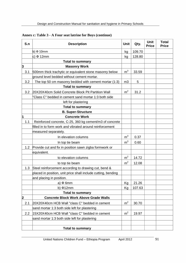
Design and Construction Manual for sanitation and hygiene in Primary Schools
United Nations Children Fund – Ethiopia Program April 2012 91
Annex c: Table 3 - A Four seat latrine for Boys (continue)
S.n Description Unit Qty. Unit Price
Total Price
b) Ф 10mm kg 109.70
c) Ф 12mm kg 128.80
Total to summary
3 Masonry Work
3.1 500mm thick trachytic or equivalent stone masonry below m3 33.59
ground level bedded without cement mortar.
3.2 The top 50 cm masonry bedded with cement mortar (1:3) m3 5
Total to summary
3.2 20X20X40cm Solid Concrete Block Pit Partition Wall m2 31.2
"Class C" bedded in cement sand mortar 1:3 both side
left for plastering
Total to summary
B. Super-Structure
1 Concrete Work
1.1 Reinforced concrete, C-25, 360 kg cement/m3 of concrete
filled in to form work and vibrated around reinforcement
measured separately.
In elevation columns m3 0.37
In top tie beam m3 0.60
1.2 Provide cut and fix in position sawn zigba formwork or
equivalent.
to elevation columns m2 14.72
to top tie beam m2 12.08
1.3 Steel reinforcement according to drawing cut, bend &
placed in position, unit price shall include cutting, bending
and placing in position.
a) Ф 6mm Kg 21.26
b) Ф12mm Kg 107.63
Total to summary 2 Concrete Block Work Above Grade Walls
2.1 20X20X40cm HCB Wall "class C" bedded in cement m2 30.70
sand mortar 1:3 both side left for plastering
2.2 15X20X40cm HCB Wall "class C" bedded in cement m2 19.97
sand mortar 1:3 both side left for plastering
Total to summary
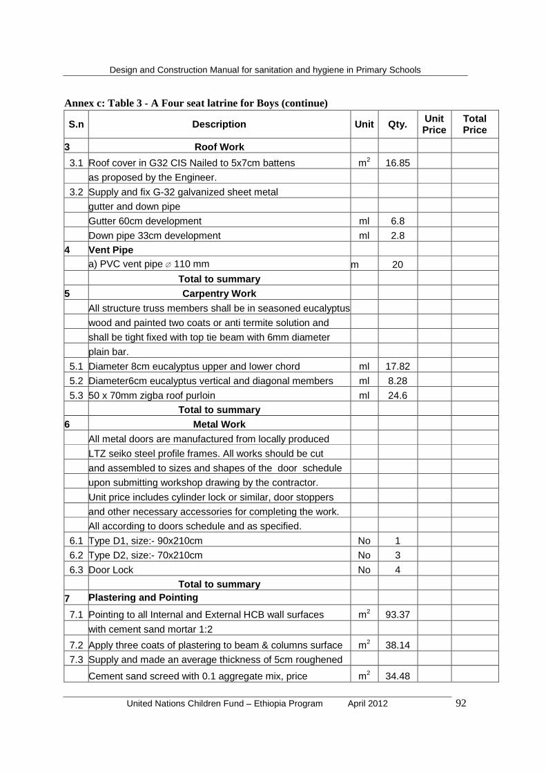
Design and Construction Manual for sanitation and hygiene in Primary Schools
United Nations Children Fund – Ethiopia Program April 2012 92
Annex c: Table 3 - A Four seat latrine for Boys (continue)
S.n Description Unit Qty. Unit Price
Total Price
3 Roof Work
3.1 Roof cover in G32 CIS Nailed to 5x7cm battens m2 16.85
as proposed by the Engineer.
3.2 Supply and fix G-32 galvanized sheet metal
gutter and down pipe
Gutter 60cm development ml 6.8
Down pipe 33cm development ml 2.8
4 Vent Pipe
a) PVC vent pipe ø 110 mm m 20
Total to summary 5 Carpentry Work
All structure truss members shall be in seasoned eucalyptus
wood and painted two coats or anti termite solution and
shall be tight fixed with top tie beam with 6mm diameter
plain bar.
5.1 Diameter 8cm eucalyptus upper and lower chord ml 17.82
5.2 Diameter6cm eucalyptus vertical and diagonal members ml 8.28
5.3 50 x 70mm zigba roof purloin ml 24.6
Total to summary 6 Metal Work
All metal doors are manufactured from locally produced
LTZ seiko steel profile frames. All works should be cut
and assembled to sizes and shapes of the door schedule
upon submitting workshop drawing by the contractor.
Unit price includes cylinder lock or similar, door stoppers
and other necessary accessories for completing the work.
All according to doors schedule and as specified.
6.1 Type D1, size:- 90x210cm No 1
6.2 Type D2, size:- 70x210cm No 3
6.3 Door Lock No 4
Total to summary 7 Plastering and Pointing
7.1 Pointing to all Internal and External HCB wall surfaces m2 93.37
with cement sand mortar 1:2
7.2 Apply three coats of plastering to beam & columns surface m2 38.14
7.3 Supply and made an average thickness of 5cm roughened
Cement sand screed with 0.1 aggregate mix, price m2 34.48
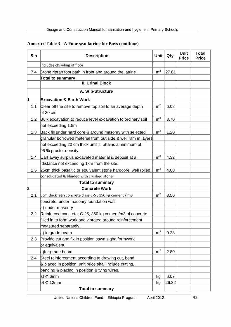
Design and Construction Manual for sanitation and hygiene in Primary Schools
United Nations Children Fund – Ethiopia Program April 2012 93
Annex c: Table 3 - A Four seat latrine for Boys (continue)
S.n Description Unit Qty. Unit Price
Total Price
Includes chiseling of floor.
7.4 Stone riprap foot path in front and around the latrine m2 27.61
Total to summary
II. Urinal Block
A. Sub -Structure
1 Excavation & Earth Work
1.1 Clear off the site to remove top soil to an average depth m2 6.08
of 30 cm
1.2 Bulk excavation to reduce level excavation to ordinary soil m3 3.70
not exceeding 1.5m
1.3 Back fill under hard core & around masonry with selected m3 1.20
granular borrowed material from out side & well ram in layers
not exceeding 20 cm thick until it attains a minimum of
95 % proctor density.
1.4 Cart away surplus excavated material & deposit at a m3 4.32
distance not exceeding 1km from the site.
1.5 25cm thick basaltic or equivalent stone hardcore, well rolled, m2 4.00
consolidated & blinded with crushed stone
Total to summary 2 Concrete Work
2.1 5cm thick lean concrete class C-5 , 150 kg cement / m3 m2 3.50
concrete, under masonry foundation wall.
a) under masonry
2.2 Reinforced concrete, C-25, 360 kg cement/m3 of concrete
filled in to form work and vibrated around reinforcement
measured separately.
a) in grade beam m3 0.28
2.3 Provide cut and fix in position sawn zigba formwork
or equivalent.
a)for grade beam m2 2.80
2.4 Steel reinforcement according to drawing cut, bend
& placed in position, unit price shall include cutting,
bending & placing in position & tying wires.
a) Ф 6mm kg 6.07
b) Ф 12mm kg 26.82
Total to summary

Design and Construction Manual for sanitation and hygiene in Primary Schools
United Nations Children Fund – Ethiopia Program April 2012 94
Annex c: Table 3 - A Four seat latrine for Boys (continue)
S.n Description Unit Qty. Unit Price
Total Price
3 Stone masonry
3.1 500mm thick trachytic or equivalent stone masonry below m3 1.32
ground level bedded in cement mortar (1:4) in full joints.
3.2 Urinal trough masonry work m3 0.553
Total to summary B. Super-Structure
1 Concrete work
1.1 Reinforced concrete, C-25, 360 kg cement/m3 of concrete
filled in to form work and vibrated around reinforcement
measured separately.
a) in elevation columns m3 0.12
1.2 Provide cut and fix in position sawn zigba formwork or
equivalent.
a) to elevation columns m2 4.80
1.3 Steel reinforcement according to drawing cut, bend &
placed in position, unit price shall include cutting, bending
& placing in position.
a) Ф 6mm Kg 2.70
b) Ф12mm Kg 12.08
Total to summary 2 Concrete Block Work Above Grade Walls
2.1 20X20X40cm HCB Wall "class B" bedded in cement m2 8.10
sand mortar 1:3 both side left for plastering
Total to summary 3 Finishing work
3.1 Apply three coats of plastering to internal wall surface m2 3.24
3.2 Pointing to Internal and External HCB wall surfaces m2 12.96
with cement sand mortar 1:2
3.3 Apply three coats of plastering to beam & columns surface m2 5.20
3.4 Plastering urinal trough m2 3.22
3.5 Supply and made an average thickness of 5cm roughened
Cement sand screed with 0.1 aggregate mix, price Includes m2 4.00
chiseling of floor.
Total to summary

Design and Construction Manual for sanitation and hygiene in Primary Schools
United Nations Children Fund – Ethiopia Program April 2012 95
Annex c: Table 3 - A Four seat latrine for Boys (continue)
S. n. Description Unit Qty. Unit Price
Total Price
4 Painting
4.1 Apply three coats of approved type oil paint to internal m2 5.40
plastered wall surface H=1000
Total to summary
III. Hand wash area
1 water trough masonry work
1.1400 mm thick trachytic or equivalent stone masonry m3 0.992
above ground level bedded in cement mortar (1:3) in full
Joints.
1.2Apply three coats of plastering to External trough m2 5.68
surface
1.3Supply & install a 25 lit fiber plastic ground water tank No. 4
with an out let ½ ‘ pipe price shall include fixing
in position and complete the system with all its necessary
Accessories to make the system workable.
Total to summary GRAND TOTAL

United Nations Children Fund – Ethiopia Program April 2012 96
REFERENCES
Abbott, Stephen P. 2005. Hand dug well: Choice of Technology and Construction Manual.
Cairncross, Sandy, and Richard Feachem, 1999. Environmental Health Engineering in the tropics. An introductory text. Second Edition.
Curtis, V., and Cairncross, S (2003). Effect of washing hands with soap on diarrhoea risk in the community: A systematic review. The Lancet, 3(5): 275-281.
Density of materials. http/: WWW. SI metric.co.uk
FDRE. Ministry of Health. 2005. National Hygiene and “on-site” Sanitation Protocol.
Ghosh S, Sengupta P G, Mondal S K, Banu M K, Gupta D N and Sircar B K, 1997, Risk behavioural practices of rural mothers as determinant of childhood dairrhoea, Journal of Communicable Diseases, 1: 7-14.
Ghosh S, Sengupta P G, Mondal S K, Banu M K, Gupta D N and Sircar B K, 1997, Risk behavioural practices of rural mothers as determinant of childhood dairrhoea, Journal of Communicable Diseases, 1: 7-14.
Gotaas, B. H. 1956. Sanitary Disposal and Reclamation of Organic Wastes, World Health Organization.
Hoque B A and Briend A, 1991, A comparison of local hand washing agents in Bangladesh, Journal of Tropical Medicine and Hygiene, 94: 61-64.
Hoque B A, Mahalanabis D, Alam M J and Islam M S, 1995, Post-defecation handwashing in Bangladesh: practice and efficiency perspectives, Public Health, 109: 15-24
Khan MU, 1982, Interruption of shigellosis by hand washing, Transactions of the Royal Society of Tropical Medicine and Hygiene, 76(2): 164-8
Moorijman, A. Caroline Van den Berg, Lene Odum ? Toolkit on Hygiene Sanitation and Water in Schools. Publication of UNICEF and Water and Sanitation Program of the World Bank.
MoWE, 2006. Rural Water Supply and Sanitation Manual. August 2006
MoWR, 1999. Guidelines for Water Quality. Unofficial Publication of the Ministry of Water Resources. Addis Abeba, Ethiopia
Reed, B.; Shaw, R. (2008). Sanitation for primary schools in Africa. Loughborough, UK, Water, Engineering and Development Centre, Loughborough University of Technology, WEDC
Save the Children-USA, March 2009, Improving water and sanitation in schools and communities: Successes and lessons learned from Nasirnagar, Bangladesh
United Nations Children Fund – Ethiopia Program April 2012 97
UNICEF -Lilongwe, MW; Malawi. Government -MW (2005). School water sanitation and hygiene education : a manual for planning, construction and supervision of facilities. Lilongwe, Malawi, UNICEF
UNICEF, 2002, School Sanitation and Hygiene Education-India: IRC Technical Pater Series 39.
UNICEF, IRC International Water and Sanitation Centre, 1998: A manual on school sanitation and hygiene.
WHO. 2005. Water, Sanitation and Hygiene. CD-ROM
World Health Organization, (1993), Guidelines for Drinking Water Quality, 2nd ed., Vol. 3 – Surveillance of Community Supplies