Embed Size (px)
Citation preview
Hugh D. Ronald, P.E.Senior Structural EngineerJE SverdrupJacksonville, Florida
Post-tensioned bulb-tee girders provide anextremely cost-effective structural system forbridge construction. Use of high strength concreteand further refinement of the structural systempromises to yield longer spans, while providingeven greater economy and durability. However,the analysis, design and construction of aprestressed, post-tensioned bulb-tee girder bridgerequires careful consideration of a multitude offactors. This article attempts to outline theessential design and construction considerationsfor a composite prestressed and post-tensionedsystem in accordance with the AASHTO LRFDBridge Design Specifications. The structuralsystem reviewed consists of precast, pretensionedbulb-tee girders, field spliced and post-tensionedin two stages for a continuous composite structuralsystem spanning three to five spans. This type ofstructural system has been used extensively andeconomically for bridges requiring moderatelylong spans ranging up to 320 ft (97.5 m).
Precast, prestressed bulb-tee girders post-tensioned forcontinuity have proven to be one of the most cost-effective structural systems for bridge spans of 200
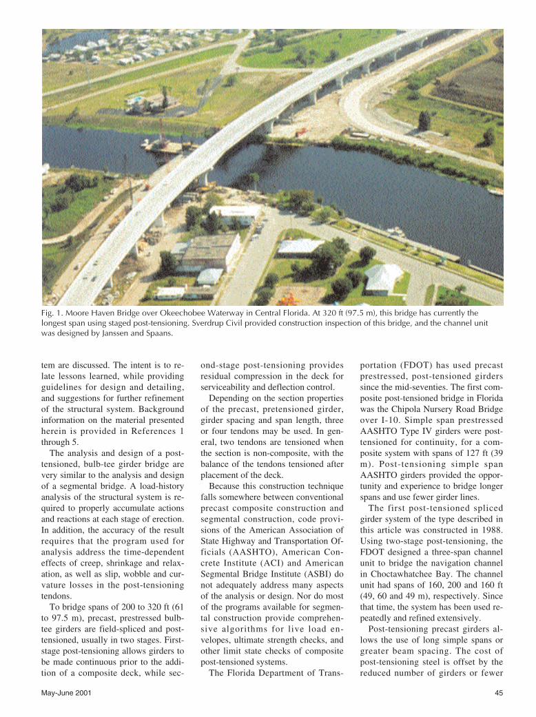
to 320 ft (61 to 97.5 m). In the past ten years, this structuralsystem has been used extensively, particularly for intra-coastal crossings in the state of Florida (see Fig. 1).
This article addresses key aspects of the design and con-struction of these structures. Rather than expound on thespecifics of a particular project, details of the structural sys-
Design and ConstructionConsiderations for ContinuousPost-Tensioned Bulb-Tee Girder Bridges
44 PCI JOURNAL
This article reflects the author’s experiencewith post-tensioned spliced girder bridgesover the past ten years, during which he haspracticed both as a bridge designer andconstruction engineer.
May-June 2001 45
tem are discussed. The intent is to re-late lessons learned, while providingguidelines for design and detailing,and suggestions for further refinementof the structural system. Backgroundinformation on the material presentedherein is provided in References 1through 5.
The analysis and design of a post-tensioned, bulb-tee girder bridge arevery similar to the analysis and designof a segmental bridge. A load-historyanalysis of the structural system is re-quired to properly accumulate actionsand reactions at each stage of erection.In addition, the accuracy of the resultrequires that the program used foranalysis address the time-dependenteffects of creep, shrinkage and relax-ation, as well as slip, wobble and cur-vature losses in the post-tensioningtendons.
To bridge spans of 200 to 320 ft (61to 97.5 m), precast, prestressed bulb-tee girders are field-spliced and post-tensioned, usually in two stages. First-stage post-tensioning allows girders tobe made continuous prior to the addi-tion of a composite deck, while sec-
ond-stage post-tensioning providesresidual compression in the deck forserviceability and deflection control.
Depending on the section propertiesof the precast, pretensioned girder,girder spacing and span length, threeor four tendons may be used. In gen-eral, two tendons are tensioned whenthe section is non-composite, with thebalance of the tendons tensioned afterplacement of the deck.
Because this construction techniquefalls somewhere between conventionalprecast composite construction andsegmental construction, code provi-sions of the American Association ofState Highway and Transportation Of-ficials (AASHTO), American Con-crete Institute (ACI) and AmericanSegmental Bridge Institute (ASBI) donot adequately address many aspectsof the analysis or design. Nor do mostof the programs available for segmen-tal construction provide comprehen-sive algorithms for live load en-velopes, ultimate strength checks, andother limit state checks of compositepost-tensioned systems.
The Florida Department of Trans-
portation (FDOT) has used precastprestressed, post-tensioned girderssince the mid-seventies. The first com-posite post-tensioned bridge in Floridawas the Chipola Nursery Road Bridgeover I-10. Simple span prestressedAASHTO Type IV girders were post-tensioned for continuity, for a com-posite system with spans of 127 ft (39m). Post-tensioning simple spanAASHTO girders provided the oppor-tunity and experience to bridge longerspans and use fewer girder lines.
The first post-tensioned splicedgirder system of the type described inthis article was constructed in 1988.Using two-stage post-tensioning, theFDOT designed a three-span channelunit to bridge the navigation channelin Choctawhatchee Bay. The channelunit had spans of 160, 200 and 160 ft(49, 60 and 49 m), respectively. Sincethat time, the system has been used re-peatedly and refined extensively.
Post-tensioning precast girders al-lows the use of long simple spans orgreater beam spacing. The cost ofpost-tensioning steel is offset by thereduced number of girders or fewer
Fig. 1. Moore Haven Bridge over Okeechobee Waterway in Central Florida. At 320 ft (97.5 m), this bridge has currently thelongest span using staged post-tensioning. Sverdrup Civil provided construction inspection of this bridge, and the channel unitwas designed by Janssen and Spaans.
46 PCI JOURNAL
substructure units. But the economy ofthe system is greatest when spanlengths are pushed beyond the practi-cal limits of standard precast shapes,and advantage is taken of structuralcontinuity.
The practical limits of current andfuture “standard” shapes are site ac-cess restrictions, handling loads, andtransportation requirements. It is im-practical or uneconomical to transporta 200 ft (61 m) girder on most roads.Similarly, it is impractical to handleand erect massive structural elementsusing anything but highly specializedlifting equipment. Hence, there is acompelling need to develop a segmen-tal approach to precast compositegirder design.
CONTINUOUS POST-TENSIONED STRUCTURAL
SYSTEMSTwo very similar structural systems
are discussed. The first is a three-spanunit, typical of the structural systemsused for intracoastal crossings inFlorida. Several variations of thethree-span unit have been designed
and constructed in Florida. One of themost recently designed three-span sys-tems is the channel unit of the Won-derwood Connector, in Jacksonville,Florida. The second system discussedis a five-span unit, proposed for the St.George Island design-build project.
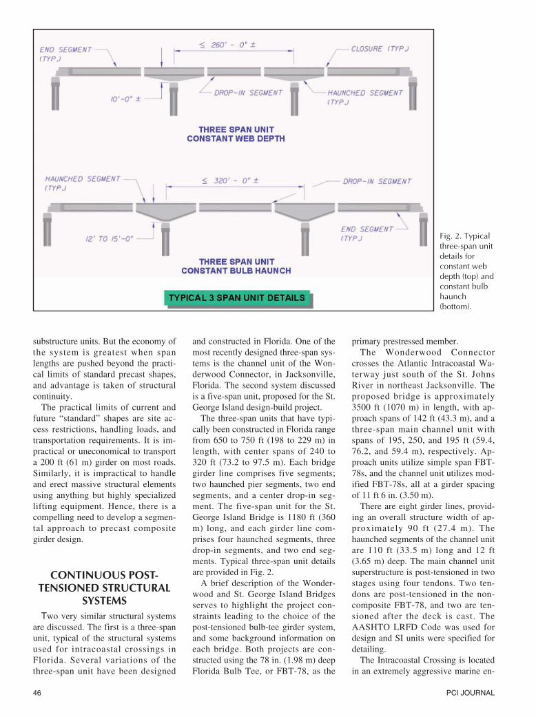
The three-span units that have typi-cally been constructed in Florida rangefrom 650 to 750 ft (198 to 229 m) inlength, with center spans of 240 to320 ft (73.2 to 97.5 m). Each bridgegirder line comprises five segments;two haunched pier segments, two endsegments, and a center drop-in seg-ment. The five-span unit for the St.George Island Bridge is 1180 ft (360m) long, and each girder line com-prises four haunched segments, threedrop-in segments, and two end seg-ments. Typical three-span unit detailsare provided in Fig. 2.
A brief description of the Wonder-wood and St. George Island Bridgesserves to highlight the project con-straints leading to the choice of thepost-tensioned bulb-tee girder system,and some background information oneach bridge. Both projects are con-structed using the 78 in. (1.98 m) deepFlorida Bulb Tee, or FBT-78, as the
primary prestressed member.The Wonderwood Connector
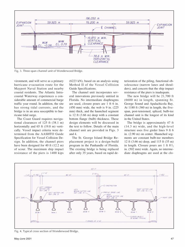
crosses the Atlantic Intracoastal Wa-terway just south of the St. JohnsRiver in northeast Jacksonville. Theproposed bridge is approximately3500 ft (1070 m) in length, with ap-proach spans of 142 ft (43.3 m), and athree-span main channel unit withspans of 195, 250, and 195 ft (59.4,76.2, and 59.4 m), respectively. Ap-proach units utilize simple span FBT-78s, and the channel unit utilizes mod-ified FBT-78s, all at a girder spacingof 11 ft 6 in. (3.50 m).
There are eight girder lines, provid-ing an overall structure width of ap-proximately 90 ft (27.4 m). Thehaunched segments of the channel unitare 110 ft (33.5 m) long and 12 ft(3.65 m) deep. The main channel unitsuperstructure is post-tensioned in twostages using four tendons. Two ten-dons are post-tensioned in the non-composite FBT-78, and two are ten-sioned after the deck is cast. TheAASHTO LRFD Code was used fordesign and SI units were specified fordetailing.
The Intracoastal Crossing is locatedin an extremely aggressive marine en-
Fig. 2. Typicalthree-span unitdetails forconstant webdepth (top) andconstant bulbhaunch(bottom).
May-June 2001 47
vironment, and will serve as a primaryhurricane evacuation route for theMayport Naval Station and nearbycoastal residents. The Atlantic Intra-coastal Waterway experiences a con-siderable amount of commercial bargetraffic year round. In addition, the sitehas strong tidal currents, and thebridge is in an area susceptible to hur-ricane tidal surge.
The Coast Guard requires naviga-tional clearances of 125 ft (38.1 m)horizontally and 65 ft (19.8 m) verti-cally. Vessel impact criteria were de-termined from the AASHTO GuideSpecification for Vessel Collision De-sign. In addition, the channel piershave been designed for 40 ft (12.2 m)of scour. The maximum ship impactresistance of the piers is 1400 kips
(6223 kN), based on an analysis usingMethod II of the Vessel CollisionGuide Specifications.
The channel unit incorporates sev-eral innovations previously untried inFlorida. No intermediate diaphragmsare used, closure pours are 1 ft 6 in.(450 mm) wide, the web is 9 in. (225mm) thick, and the haunched segmentis 12 ft (3.66 m) deep with a constantbottom flange (bulb) thickness. Thesedesign elements will be discussed inthe text to follow. Details of the mainchannel unit are provided in Figs. 3and 4.
The St. George Island Bridge Re-placement project is a design-buildprogram in the Panhandle of Florida.The existing bridge is being replacedafter only 35 years, based on rapid de-
terioration of the piling, functional ob-solescence (narrow lanes and shoul-ders), and concern that the ship impactresistance of the piers is inadequate.
The new bridge will be 21,700 ft(6600 m) in length, spanning St.George Sound and Apalachicola Bay.At 1180 ft (360 m) in length, the five-span, post-tensioned, spliced, bulb-teechannel unit is the longest of its kindin the United States.
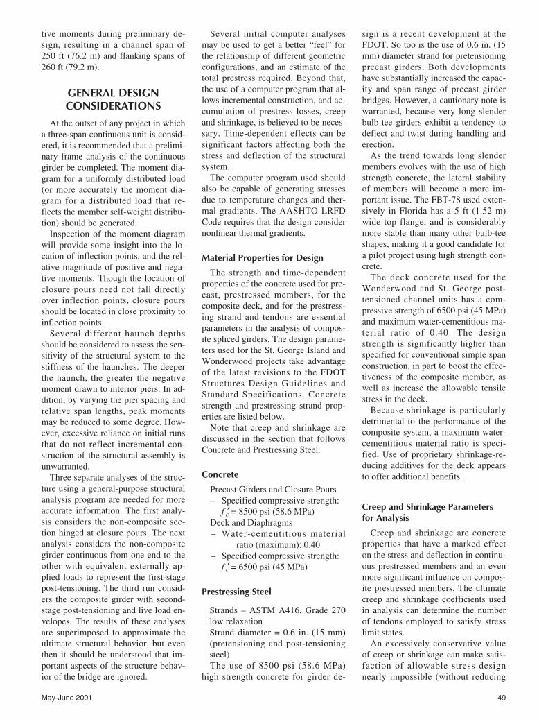
The bridge is approximately 47 ft(14.3 m) wide, and the high-levelstructure uses five girder lines 9 ft 6in. (2.90 m) on center. Haunched seg-ments are constant bulb-tee members12 ft (3.66 m) deep, and 115 ft (35 m)in length. Closure pours are 1 ft 81/2
in. (502 mm) wide. Again, no interme-diate diaphragms are used at the clo-
Fig. 3. Three-span channel unit of Wonderwood Bridge.
Fig. 4. Typical cross section of Wonderwood Bridge.
48 PCI JOURNAL
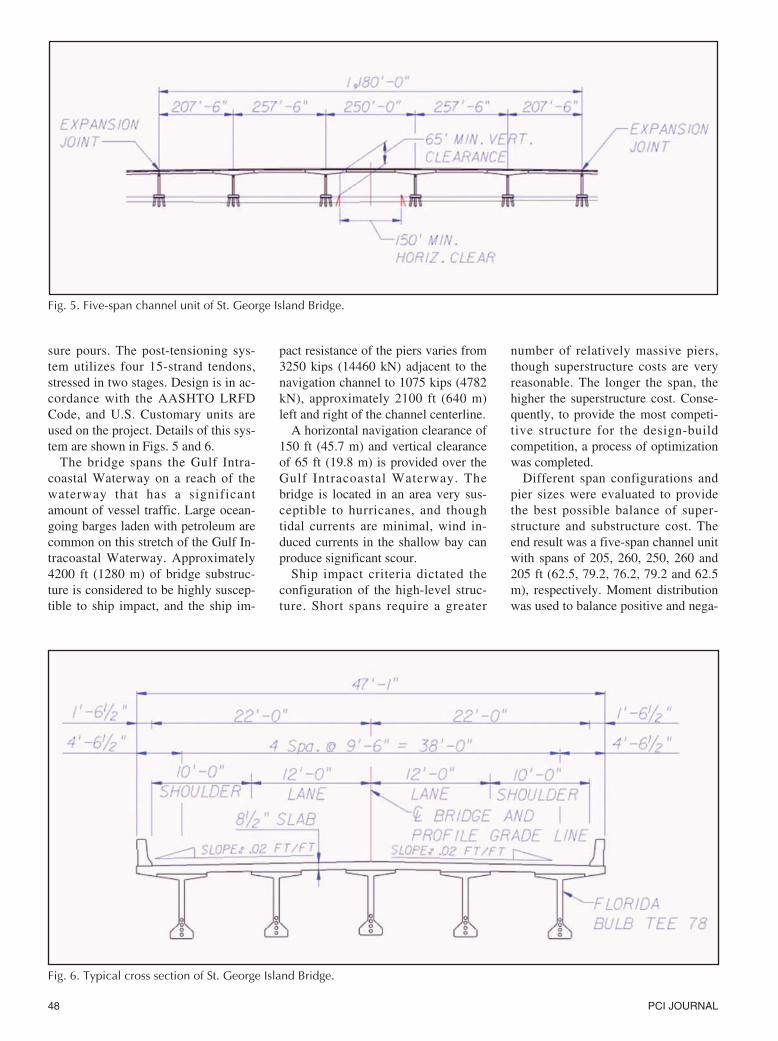
sure pours. The post-tensioning sys-tem utilizes four 15-strand tendons,stressed in two stages. Design is in ac-cordance with the AASHTO LRFDCode, and U.S. Customary units areused on the project. Details of this sys-tem are shown in Figs. 5 and 6.
The bridge spans the Gulf Intra-coastal Waterway on a reach of thewaterway that has a significantamount of vessel traffic. Large ocean-going barges laden with petroleum arecommon on this stretch of the Gulf In-tracoastal Waterway. Approximately4200 ft (1280 m) of bridge substruc-ture is considered to be highly suscep-tible to ship impact, and the ship im-
pact resistance of the piers varies from3250 kips (14460 kN) adjacent to thenavigation channel to 1075 kips (4782kN), approximately 2100 ft (640 m)left and right of the channel centerline.
A horizontal navigation clearance of150 ft (45.7 m) and vertical clearanceof 65 ft (19.8 m) is provided over theGulf Intracoastal Waterway. Thebridge is located in an area very sus-ceptible to hurricanes, and thoughtidal currents are minimal, wind in-duced currents in the shallow bay canproduce significant scour.
Ship impact criteria dictated theconfiguration of the high-level struc-ture. Short spans require a greater
number of relatively massive piers,though superstructure costs are veryreasonable. The longer the span, thehigher the superstructure cost. Conse-quently, to provide the most competi-tive structure for the design-buildcompetition, a process of optimizationwas completed.
Different span configurations andpier sizes were evaluated to providethe best possible balance of super-structure and substructure cost. Theend result was a five-span channel unitwith spans of 205, 260, 250, 260 and205 ft (62.5, 79.2, 76.2, 79.2 and 62.5m), respectively. Moment distributionwas used to balance positive and nega-
Fig. 5. Five-span channel unit of St. George Island Bridge.
Fig. 6. Typical cross section of St. George Island Bridge.
May-June 2001 49
tive moments during preliminary de-sign, resulting in a channel span of250 ft (76.2 m) and flanking spans of260 ft (79.2 m).
GENERAL DESIGNCONSIDERATIONS
At the outset of any project in whicha three-span continuous unit is consid-ered, it is recommended that a prelimi-nary frame analysis of the continuousgirder be completed. The moment dia-gram for a uniformly distributed load(or more accurately the moment dia-gram for a distributed load that re-flects the member self-weight distribu-tion) should be generated.
Inspection of the moment diagramwill provide some insight into the lo-cation of inflection points, and the rel-ative magnitude of positive and nega-tive moments. Though the location ofclosure pours need not fall directlyover inflection points, closure poursshould be located in close proximity toinflection points.
Several different haunch depthsshould be considered to assess the sen-sitivity of the structural system to thestiffness of the haunches. The deeperthe haunch, the greater the negativemoment drawn to interior piers. In ad-dition, by varying the pier spacing andrelative span lengths, peak momentsmay be reduced to some degree. How-ever, excessive reliance on initial runsthat do not reflect incremental con-struction of the structural assembly isunwarranted.
Three separate analyses of the struc-ture using a general-purpose structuralanalysis program are needed for moreaccurate information. The first analy-sis considers the non-composite sec-tion hinged at closure pours. The nextanalysis considers the non-compositegirder continuous from one end to theother with equivalent externally ap-plied loads to represent the first-stagepost-tensioning. The third run consid-ers the composite girder with second-stage post-tensioning and live load en-velopes. The results of these analysesare superimposed to approximate theultimate structural behavior, but eventhen it should be understood that im-portant aspects of the structure behav-ior of the bridge are ignored.
Several initial computer analysesmay be used to get a better “feel” forthe relationship of different geometricconfigurations, and an estimate of thetotal prestress required. Beyond that,the use of a computer program that al-lows incremental construction, and ac-cumulation of prestress losses, creepand shrinkage, is believed to be neces-sary. Time-dependent effects can besignificant factors affecting both thestress and deflection of the structuralsystem.
The computer program used shouldalso be capable of generating stressesdue to temperature changes and ther-mal gradients. The AASHTO LRFDCode requires that the design considernonlinear thermal gradients.
Material Properties for Design
The strength and time-dependentproperties of the concrete used for pre-cast, prestressed members, for thecomposite deck, and for the prestress-ing strand and tendons are essentialparameters in the analysis of compos-ite spliced girders. The design parame-ters used for the St. George Island andWonderwood projects take advantageof the latest revisions to the FDOTStructures Design Guidelines andStandard Specifications. Concretestrength and prestressing strand prop-erties are listed below.
Note that creep and shrinkage arediscussed in the section that followsConcrete and Prestressing Steel.
Concrete
Precast Girders and Closure Pours– Specified compressive strength:
f ′c = 8500 psi (58.6 MPa)Deck and Diaphragms– Water-cementitious material
ratio (maximum): 0.40– Specified compressive strength:
f ′c = 6500 psi (45 MPa)
Prestressing Steel
Strands – ASTM A416, Grade 270low relaxationStrand diameter = 0.6 in. (15 mm)(pretensioning and post-tensioningsteel)The use of 8500 psi (58.6 MPa)
high strength concrete for girder de-
sign is a recent development at theFDOT. So too is the use of 0.6 in. (15mm) diameter strand for pretensioningprecast girders. Both developmentshave substantially increased the capac-ity and span range of precast girderbridges. However, a cautionary note iswarranted, because very long slenderbulb-tee girders exhibit a tendency todeflect and twist during handling anderection.
As the trend towards long slendermembers evolves with the use of highstrength concrete, the lateral stabilityof members will become a more im-portant issue. The FBT-78 used exten-sively in Florida has a 5 ft (1.52 m)wide top flange, and is considerablymore stable than many other bulb-teeshapes, making it a good candidate fora pilot project using high strength con-crete.
The deck concrete used for theWonderwood and St. George post-tensioned channel units has a com-pressive strength of 6500 psi (45 MPa)and maximum water-cementitious ma-terial ratio of 0.40. The designstrength is significantly higher thanspecified for conventional simple spanconstruction, in part to boost the effec-tiveness of the composite member, aswell as increase the allowable tensilestress in the deck.
Because shrinkage is particularlydetrimental to the performance of thecomposite system, a maximum water-cementitious material ratio is speci-fied. Use of proprietary shrinkage-re-ducing additives for the deck appearsto offer additional benefits.
Creep and Shrinkage Parametersfor Analysis
Creep and shrinkage are concreteproperties that have a marked effecton the stress and deflection in continu-ous prestressed members and an evenmore significant influence on compos-ite prestressed members. The ultimatecreep and shrinkage coefficients usedin analysis can determine the numberof tendons employed to satisfy stresslimit states.
An excessively conservative valueof creep or shrinkage can make satis-faction of allowable stress designnearly impossible (without reducing
50 PCI JOURNAL
span length or using deeper members).On the other hand, unconservative val-ues of creep or shrinkage will yieldunconservative estimates of tendon re-quirements, and provide stress resul-tants that will not be obtained in thefield.
In the absence of project-specifictesting for determination of creep andshrinkage coefficients, values of ulti-mate creep and shrinkage should beused that have been obtained throughprevious projects or mix design test-ing. The FDOT has provided conser-vative values of creep and shrinkageto be used with ACI Code provisionsfor time-dependent analysis of post-tensioned structural systems.
Based on research conducted at theUniversity of Florida, an ultimatecreep coefficient of 2.0 and ultimateshrinkage coefficient of 0.0004 havebeen specified for typical mix designsutilized by the FDOT for precast, pre-stressed girders. No distinction be-tween the coefficients of deck and pre-cast concrete mixes is made. Furtherresearch is probably warranted forcomposite systems, to better estimatecreep and shrinkage in deck concreteoriginating at ready-mix batch plants.
It is useful to run analyses of thestructural behavior of the post-ten-sioned system under investigationusing several different values of creepand shrinkage, alternately varyingcreep and shrinkage. This analysisserves to underscore the effect eachvariable has on the system, and thesensitivity of the structure to varia-tions in creep and shrinkage. Severalgeneral observations regarding creepand shrinkage are warranted.
Examples of problems that havemanifested themselves in the design ofcomposite spliced bulb-tee girderbridges follow.
• First is the differential shrinkagebetween a precast girder, perhaps 120to 180 days old, and a deck pour madeafter first stage post-tensioning. It isparticularly detrimental over haunchedgirders where the deck will undergo
tension due to restraint of shrinkage,so that compression derived from sec-ond-stage post-tensioning of the deckis sometimes negated. Consequently,allowable tension stresses may be ex-ceeded in the deck with the applica-tion of live load and introduction ofnegative bending stresses.
• Second is the development of atensile force in the deck over the drop-in and end segments which tends tocompress the top flange of the precastgirder (through an equal and oppositereaction), and consequently reduce theeffectiveness of the prestress in thebottom of the girder.
Note that the second effect is oftenrealized in simple span structures,where the effect of deck shrinkage onmature girders tends to bow the beamdown.* These phenomena point to thenecessity of carefully selecting ashrinkage coefficient that is represen-tative of the concrete being used.
Shrinkage in composite systems cancreate sizable forces between the deckand girders. On the Wonderwood pro-ject, discussed earlier, analysis indi-cates that a 50 psi (0.345 MPa) decktension due to differential strain be-tween the deck and girder elementscast at different times occurs. Notethat the stress pertains to the final de-sign of the Wonderwood Channel unit,where every reasonable attempt wasmade to mitigate differential shrinkagestresses.
Unfortunately, even sophisticatedcomputer programs may overestimatethe shrinkage force that develops be-tween members. Programs do not pro-vide a stress reduction to reflect devel-opment of shrinkage cracks. Instead,differential strain between two mem-bers due to differing rates of shrinkageis calculated as stress, using Codespecified elastic moduli.
In addition, the tensile stress that de-velops due to differential shrinkageleads to a force unaffected by shearlag. In more tangible terms, the differ-ential strain in a deck element is notreduced by shear lag between the deckand girder. Nor is there a lessening oftension due to development of shrink-age cracks.
The stress that develops due to dif-ferential shrinkage may approach theallowable tensile stress specified by
the AASHTO and ACI Codes, andcurrent software does not addresscracking and subsequent stress relief.Shrinkage stresses in excess of 100 psi(0.69 MPa) are sometimes computedusing programs performing time-de-pendent analysis.
There are effective countermeasuresthat can be taken to alleviate differen-tial shrinkage:
• First, low water-cementitious ma-terials ratios in the deck concrete, orshrinkage-reducing admixtures may beused. Use of low shrinkage deck con-crete will reduce tensile stresses sig-nificantly. The author has performedanalyses using shrinkage coefficientsranging from 0.0004 to 0.0003 for thedeck, and a constant of 0.0004 for thegirders. These analyses show dramaticimprovement in the stress distributiondue to shrinkage.
• Second, realization that differen-tial shrinkage is greatest when the agedifference between the deck and girderis pronounced offers a viable solution.Haunched members, if cast late in theproduction schedule, will still be rela-tively young when the deck is placed.This will reduce the magnitude of dif-ferential shrinkage. The issue of thecasting schedule as it affects time-dependent analysis will be further dis-cussed in the text to follow.
Creep can have similar effects onthe performance of a composite sys-tem. The effect of creep is lessmarked, since it is primarily a functionof the applied load. A load must bepresent to induce creep. Because creepwill be greatest in young concrete, itmay be advisable to delay post-tensioning to reduce creep losses. Onthe other hand, creep will tend to shedload from highly stressed members toless highly stressed members.
One notable effect of creep on boththree- and five-span units is thechange in stress that occurs betweenthe beginning of service life and theend of service life. It has generallybeen found that the deck compressionover haunches relaxes with time, andthat end and drop-in girder bottomflange compressive stress also relaxes.The effect is essentially a reduction inthe system stiffness over time. Conse-quently, it is good practice to reviewservice load stresses at both the begin-
* A similar phenomenon may be responsible for the dif-ference between measured and predicted camber inFlorida Bulb Tee (FBT) girders. Shrinkage in the ex-posed top flange of the girder can result in web compres-sion. The resultant compression in the top of the webmay counteract the effective prestress in the member.
May-June 2001 51
ning and end of the projected servicelife of this structure.
Effect of Casting Schedule onAnalysis and Design
It is apparent from the discussion ofcreep and shrinkage parameters abovethat the schedule used to construct acomposite segmental structure can sig-nificantly affect the calculated stressesin deck and girder members. In addi-tion, it is unlikely that the design engi-neer will have control over the castingschedule used by the contractor build-ing the bridge once it is designed.Consequently, it is good practice toproduce at least two different castingschedules for incremental constructionof the structure.
The first should reflect an “opti-mized” schedule, with precast, pre-stressed members cast and deck poursmade for least detriment to the com-posite system stress distribution. Thesecond should be a casting schedulethat departs from the “optimum”schedule, so as to adversely affectmember stresses. Both should be vi-able achievable schedules.
On the one hand, the “optimum”schedule will minimize differentialshrinkage between members (all mem-bers cast and poured in the same timeframe, i.e., a compressed schedule). Atthe same time, and to the extent possi-ble and consistent with the first condi-tion, the “optimum” schedule willallow girders, deck and closure poursto cure sufficiently to reduce immedi-ate and pronounced creep (all precastand deck pours made four or moreweeks before post-tensioning) beforestressing tendons.
On the other hand, the adverseschedule will have deck pours madewell after all precast members arecured (aggravating differential shrink-age), and post-tensioning will be car-ried out as soon as the concretestrength permits (aggravating creep).These are, in the author’s opinion, theopposite ends of the spectrum as re-lated to the casting schedule.
Temperature and ThermalGradient Effects
The effect of a thermal gradient onthe ultimate strength of a continuous
concrete structure is not believed to besignificant. At ultimate strength, thecontinuous member will most likelyundergo considerable stress redistribu-tion due to cracking and subsequentredistribution of loads, including ther-mal and hyperstatic actions.
This condition is reflected in the lat-est edition of the AASHTO LRFDCode, in which the load factor appliedto the strength limit states for a ther-mal gradient is zero, without projectspecific information to the contrary. Itis noteworthy that the AASHTOLRFD Code does not consider stressesdue to thermal gradients.
The AASHTO LRFD Code doesprovide a nonlinear gradient for re-view of service limit states, and speci-fies both positive and negative temper-ature gradients in Section 3.12.3. Thethermal gradient produces two sets ofstresses that must be superimposed:Self-equilibrating stresses:
σse(y) = σ (y)restrained + [-(P/A) – (M ybar/I)]
and stresses due to an equivalent linearthermal gradient:
σ (y)equiv linear = Pc/A + (Mcy/I)
where Pc and Mc are continuity mo-ments obtained from an analysis of theequivalent linear thermal gradient onthe continuous structure.
Only a few of the computer pro-grams currently available will handle anonlinear gradient (most will handle alinear gradient), requiring manual su-perposition of the self-equilibratingstresses to obtain final results.
Stress resultants from nonlinearthermal gradients can be significant.Positive gradients tend to compress thedeck over haunches, while increasingtension in the bottom of girders nearthe center of the spans. Negative gra-dients reduce compression in the deckover haunched segments and add com-pression at the base of girders near thecenter of the spans.
Load factors in the AASHTO LRFDCode do not give much weight to ther-mal gradient stresses, since live load isgiven a load factor of 0.5 when com-bined with the thermal gradient. It isthe author’s hope that further discus-
sion of thermal gradient effects be in-cluded in future revisions of the appli-cable codes. This appears to be an areawhere further research is warranted.
Allowable Stress and UltimateStrength Design Considerations
The design of precast, prestressedmembers, as well as precast post-tensioned members, must satisfy bothallowable stress design and ultimatestrength. The LRFD Code recognizesthis by providing both strength andservice load limit states. The code pro-visions for allowable stress for pre-stressed and post-tensioned membersis intended to limit or prevent crack-ing, so as to protect strand from corro-sion. Applied to the composite post-tensioned structure, allowable stressdesign leaves some room for interpre-tation.
As a practical matter, the extremefibers of the deck and girders arechecked to verify conformance withallowable stress design. However, thedeck is neither prestressed nor post-tensioned in the sense that the sectioncontains no prestressed strand. Thedeck uses mild steel reinforcement.
The deck of a composite steel struc-ture does not have to satisfy allowablestress design. Instead, the deck is rein-forced in negative moment regions toreduce the width of potential hairlinecracks, but is not considered a part ofthe nominal moment-resisting system.
From a strength perspective, theredoes not appear to be any compellingreason to treat the deck in the post-tensioned bulb-tee composite deck anydifferently. The deck contains no pre-stressing steel. Nonetheless, currentpractice likes to provide sufficient sec-ond-stage post-tensioning to precom-press the deck against anticipated liveload bending moments and to satisfymaximum allowable tensile stresses(less than the modulus of rupture).
It is arguable that the practice oflimiting stress in deck elements isdone to ensure that the analysis prop-erly describes the stiffness of the com-posite system. Should the deck crack,the stress distribution is improperlydescribed by linear elastic behavior inthe deck. Deflections are also improp-erly described once cracks develop.
52 PCI JOURNAL
Stress in the underlying precast mem-ber increases substantially once cracksdevelop. These phenomena are noteasily modeled using standard meth-ods of analysis.
If not for the need to ensure an accu-rate model for analysis, the second-stage post-tensioning required in thebulb-tee systems might be substan-tially reduced. The amount of prestressin the bulb-tee system used to satisfyallowable stress design generally pro-vides nearly twice the steel needed bya review of strength limit states. Thisapparent discrepancy is not discussedor considered by the code at this time.It may be that future code revisions(and computer models) will addressthis issue in light of the increasingpopularity of the spliced post-ten-sioned bulb-tee design.
DETAILING AND ERECTIONCONSIDERATIONS
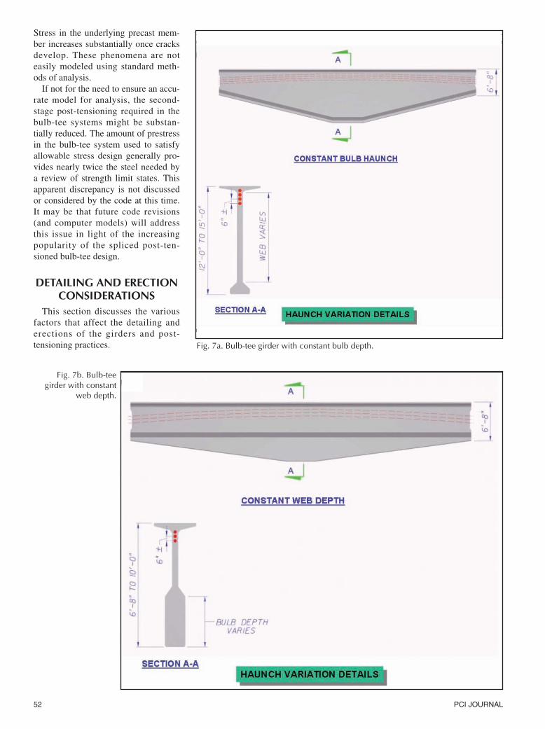
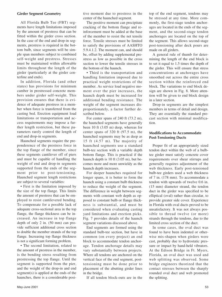
This section discusses the variousfactors that affect the detailing anderections of the girders and post-tensioning practices. Fig. 7a. Bulb-tee girder with constant bulb depth.
Fig. 7b. Bulb-teegirder with constant
web depth.
May-June 2001 53
Girder Segment Geometry
All Florida Bulb Tee (FBT) seg-ments have length limitations imposedby the amount of prestress that can befitted within the girder cross section.In the case of the end and drop-in seg-ments, prestress is required in the bot-tom bulb, since segments will be sim-ple span members subject to combinedself-weight and prestress. Stressesmust be maintained within allowablelimits throughout the length of thegirder (particularly at the girder cen-terline and ends).
In addition, Florida (and otherstates) has provisions for minimumcamber in prestressed concrete mem-bers under girder self-weight. Thisprovision ensures that there is evi-dence of adequate prestress in a mem-ber when force is transferred from thecasting bed. Erection equipment loadlimitations or transportation and ac-cess requirements may impose a fur-ther length restriction, but these pa-rameters rarely control the length ofend and drop-in segments.
Haunched segments require the pre-ponderence of the prestress force inthe top flange of the member, sincethese segments cantilever off of piersand must be capable of handling theweight of end and drop-in segmentssupported from the ends of the seg-ment prior to post-tensioning.Haunched segment length restrictionsare subject to several variables:
• First is the limitation imposed bythe size of the top flange. This limitsthe amount of prestress that can be em-ployed to resist cantilevered bending.To compensate for a possible lack ofadequate cross-sectional area in the topflange, the flange thickness can be in-creased. An increase in top flangedepth of only 2 in. (50 mm) can pro-vide sufficient additional cross sectionto double the member strands of the topflange. Increasing top flange thicknessis not a significant forming problem.
• The second limitation, related tothe amount of prestress in the member,is the bending stress resulting fromprestressing the top flange. Until thesegment is supported from the pier,and the weight of the drop-in and endsegment(s) is applied at the ends of thehaunches, there is a considerable posi-
tive moment due to prestress in thecenter of the haunched segment.
The positive moment can precipitatecracking of the bottom flange and re-inforcement must be added at the baseof the member to resist the net tensileforce. Tensile stresses must be limitedto satisfy the provisions of AASHTO5.9.4.1.2. The moment can, and shouldbe, offset by adding supplemental pre-stress as low as possible in the crosssection to lower the tensile stresses inthe bottom of the haunch.
• Third is the transportation andhandling limitation imposed due topractical weight restrictions of themember. As service load negative mo-ment over the pier increases, thehaunch depth must be increased foradditional bending resistance. Theweight of the segment increases dis-proportionately, a factor further de-scribed below.
For center spans of 240 ft (73.2 m),the haunched segments have generallybeen 10 ft (3.05 m) deep, whereas forcenter spans of 320 ft (97.5 m), thehaunched segments may be as deep as15 ft (4.57 m). The majority ofhaunched segments use a standardbulb-tee section with a variable depthbottom flange. This is practical if thehaunch depth is 10 ft (3.05 m), but be-comes more and more unwieldy as thehaunch depth increases.
For deeper haunches required forlonger spans, it is better to form thehaunch using a constant bulb thicknessto reduce the weight of the segment.The difference in weight between seg-ments with constant web depth as op-posed to constant bulb or flange thick-ness is substantial, and must beconsidered when evaluating castingyard limitations and erection picks.Fig. 7 provides details of the haunchsegment variations discussed above.
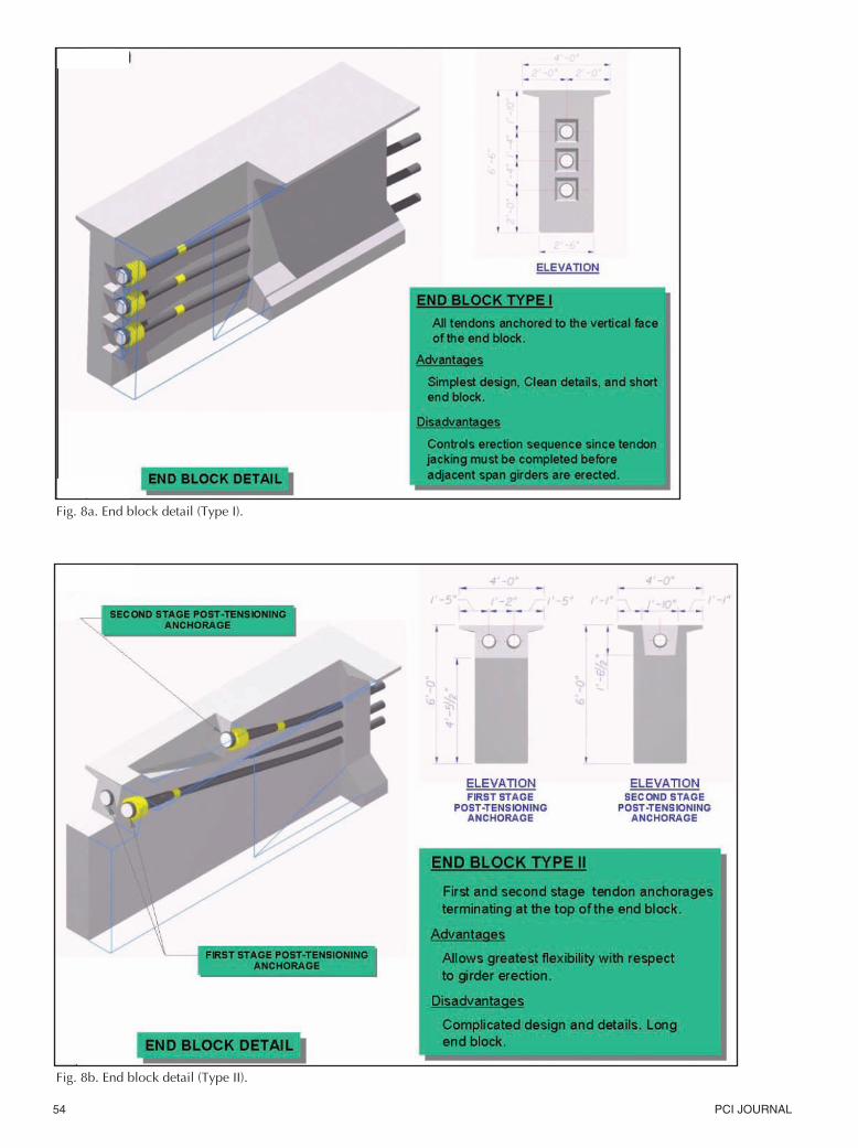
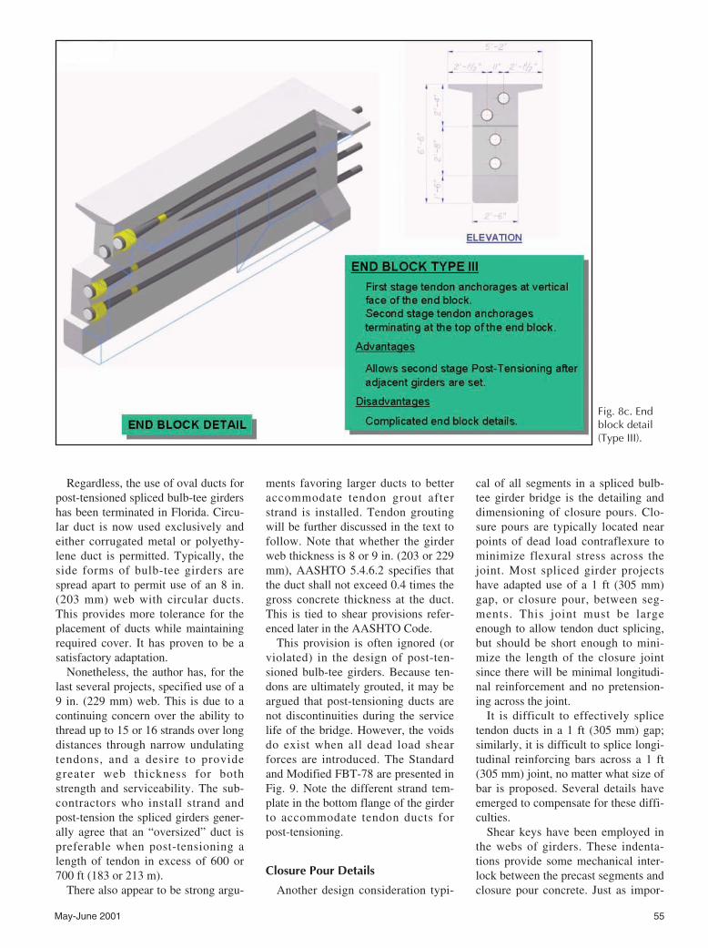
End segments are formed using thestandard bulb-tee section, but have incommon (on every project) an endblock to accommodate tendon anchor-age. Tendon anchorage details mayvary substantially between projects.Where all tendons are anchored on thevertical face of the end segment, post-tensioning must be done prior toplacement of the abutting girder linesin the bridge.
If all tendon block-outs are in the
top of the end segment, tendons maybe stressed at any time. More com-monly, the first-stage tendon anchor-ages are located in the ends of the seg-ment, and the second-stage tendonanchorages are located on the top ofthe segment. This allows second-stagepost-tensioning after deck pours aremade on all girders.
A general rule of thumb for deter-mining the length of the end block isto set it equal to 1.5 times the depth ofthe girder. This will ensure that stressconcentrations at anchorages havesmoothed out across the entire crosssection within the reinforced endblock. The variations to end block de-sign are shown in Fig. 8. More atten-tion will be given to end block designin a later section.
Drop-in segments are the simplestmembers in terms of detail and design.They are essentially the standard pre-cast section with minimal modifica-tion.
Modifications to AccommodatePost-Tensioning Ducts
Proper fit of an appropriately sizedtendon duct within the web of a bulb-tee girder must satisfy concrete coverrequirements over shear stirrups andgenerally requires adjustment of theweb thickness. Early post-tensionedbulb-tee girders used a web thicknessof 7 in. (178 mm). To accommodate atendon with upwards of twelve 0.6 in.(15 mm) diameter strand, the tendonduct in the girder was specified to beelliptical (oval) rather than circular, toprovide greater side cover. Experiencein Florida with oval ducts proved to beunsatisfactory. It was not always pos-sible to thread twelve (or more)strands through the tendons, due to thelimited cross section of the duct.
In some cases, the oval duct wasfound to have been indented or other-wise mis-shapen when girders werecast, probably due to hydrostatic pres-sure or impact by hand-held vibrators.At the Edison Bridge in Ft. Myers,Florida, an oval duct was used andweb splitting was observed. Somebridge engineers theorized that thecontact stresses between the sharplyrounded oval duct and web promotedthe splitting.
54 PCI JOURNAL
Fig. 8a. End block detail (Type I).
Fig. 8b. End block detail (Type II).
May-June 2001 55
Fig. 8c. Endblock detail(Type III).
Regardless, the use of oval ducts forpost-tensioned spliced bulb-tee girdershas been terminated in Florida. Circu-lar duct is now used exclusively andeither corrugated metal or polyethy-lene duct is permitted. Typically, theside forms of bulb-tee girders arespread apart to permit use of an 8 in.(203 mm) web with circular ducts.This provides more tolerance for theplacement of ducts while maintainingrequired cover. It has proven to be asatisfactory adaptation.
Nonetheless, the author has, for thelast several projects, specified use of a9 in. (229 mm) web. This is due to acontinuing concern over the ability tothread up to 15 or 16 strands over longdistances through narrow undulatingtendons, and a desire to providegreater web thickness for bothstrength and serviceability. The sub-contractors who install strand andpost-tension the spliced girders gener-ally agree that an “oversized” duct ispreferable when post-tensioning alength of tendon in excess of 600 or700 ft (183 or 213 m).
There also appear to be strong argu-
ments favoring larger ducts to betteraccommodate tendon grout afterstrand is installed. Tendon groutingwill be further discussed in the text tofollow. Note that whether the girderweb thickness is 8 or 9 in. (203 or 229mm), AASHTO 5.4.6.2 specifies thatthe duct shall not exceed 0.4 times thegross concrete thickness at the duct.This is tied to shear provisions refer-enced later in the AASHTO Code.
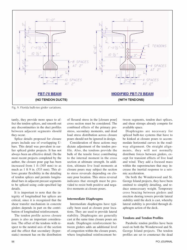
This provision is often ignored (orviolated) in the design of post-ten-sioned bulb-tee girders. Because ten-dons are ultimately grouted, it may beargued that post-tensioning ducts arenot discontinuities during the servicelife of the bridge. However, the voidsdo exist when all dead load shearforces are introduced. The Standardand Modified FBT-78 are presented inFig. 9. Note the different strand tem-plate in the bottom flange of the girderto accommodate tendon ducts forpost-tensioning.
Closure Pour Details
Another design consideration typi-
cal of all segments in a spliced bulb-tee girder bridge is the detailing anddimensioning of closure pours. Clo-sure pours are typically located nearpoints of dead load contraflexure tominimize flexural stress across thejoint. Most spliced girder projectshave adapted use of a 1 ft (305 mm)gap, or closure pour, between seg-ments. This joint must be largeenough to allow tendon duct splicing,but should be short enough to mini-mize the length of the closure jointsince there will be minimal longitudi-nal reinforcement and no pretension-ing across the joint.
It is difficult to effectively splicetendon ducts in a 1 ft (305 mm) gap;similarly, it is difficult to splice longi-tudinal reinforcing bars across a 1 ft(305 mm) joint, no matter what size ofbar is proposed. Several details haveemerged to compensate for these diffi-culties.
Shear keys have been employed inthe webs of girders. These indenta-tions provide some mechanical inter-lock between the precast segments andclosure pour concrete. Just as impor-
56 PCI JOURNAL
tantly, they provide more space to af-fect the tendon splices, and smooth outany discontinuities in the duct profilesbetween adjacent segments shouldthey occur.
Splice details proposed for closurepours include use of overlapping U-bars. This detail was prevalent in ear-lier spliced girder projects. It has notalways been an effective detail. On themost recent projects completed by theauthor, the closure pour gap has beenincreased from 1 ft (305 mm) to asmuch as 1 ft 9 in. (533 mm). This al-lows greater flexibility in the detailingof tendon splices and permits longitu-dinal bars in adjacent precast segmentsto be spliced using code-specified lapdetails.
It is important to note that the in-tegrity of longitudinal bar splices arecritical, since it is recognized that theshear transfer mechanism in concretegirders depends in part on the contri-bution of longitudinal reinforcement.
The tendon profile across closurepours is also an important considera-tion. The offset of the tendons with re-spect to the neutral axis of the sectionand the effect that secondary (hyper-static) moment has on the distribution
of flexural stress in the [closure pour]cross section must be considered. Thecombined effects of the primary pre-stress, secondary moments, and deadload stress distribution across closurepours should not be ignored in design.
Consideration of these actions maydictate adjustment of the tendon pro-file. Also, the tendons provide thebulk of the tensile force contributingto the internal moment in the crosssection at ultimate strength. In addi-tion, ultimate live load moments atclosure pours may subject the sectionto stress reversals depending on clo-sure pour location. This stress reversalindicates that strength must be pro-vided to resist both positive and nega-tive moments at closure pours.
Intermediate Diaphragms
Intermediate diaphragms have typi-cally been used at closure pour loca-tions. They are used to provide lateralstability. Diaphragms are generallycast at the same time closure pours aremade. Diaphragm reinforcement be-tween girders adds an additional levelof congestion within the closure pours,where longitudinal reinforcement be-
tween segments, tendon duct splices,and shear stirrups already compete foravailable space.
Diaphragms are necessary forspliced bulb-tee systems that have tobe kinked at closure pours to accom-modate horizontal curves in the road-way alignment. On straight align-ments, they will not normallydistribute forces between girders, ex-cept for transient effects of live loadand wind. They add a focused masswithin the superstructure that may in-crease the inertial response to a seis-mic acceleration.
On both the Wonderwood and St.George Island projects, they have beenomitted to simplify detailing, and re-duce unnecessary weight. Temporarycross bracing between girders anderection shoring towers provide lateralstability until the deck is cast, wherebylateral stability is provided through di-aphragm action of the deck.
Tendons and Tendon Profiles
Parabolic tendon profiles have beenused on both the Wonderwood and St.George Island projects. The tendonprofiles are set to counteract the dead
Fig. 9. Florida bulb-tee girder variations.
May-June 2001 57
load moments in the continuous unit.The method is essentially a load bal-ancing procedure. It reduces the mag-nitude of secondary moments by pro-viding tendon profiles that are as closeto concordant profiles as possible.
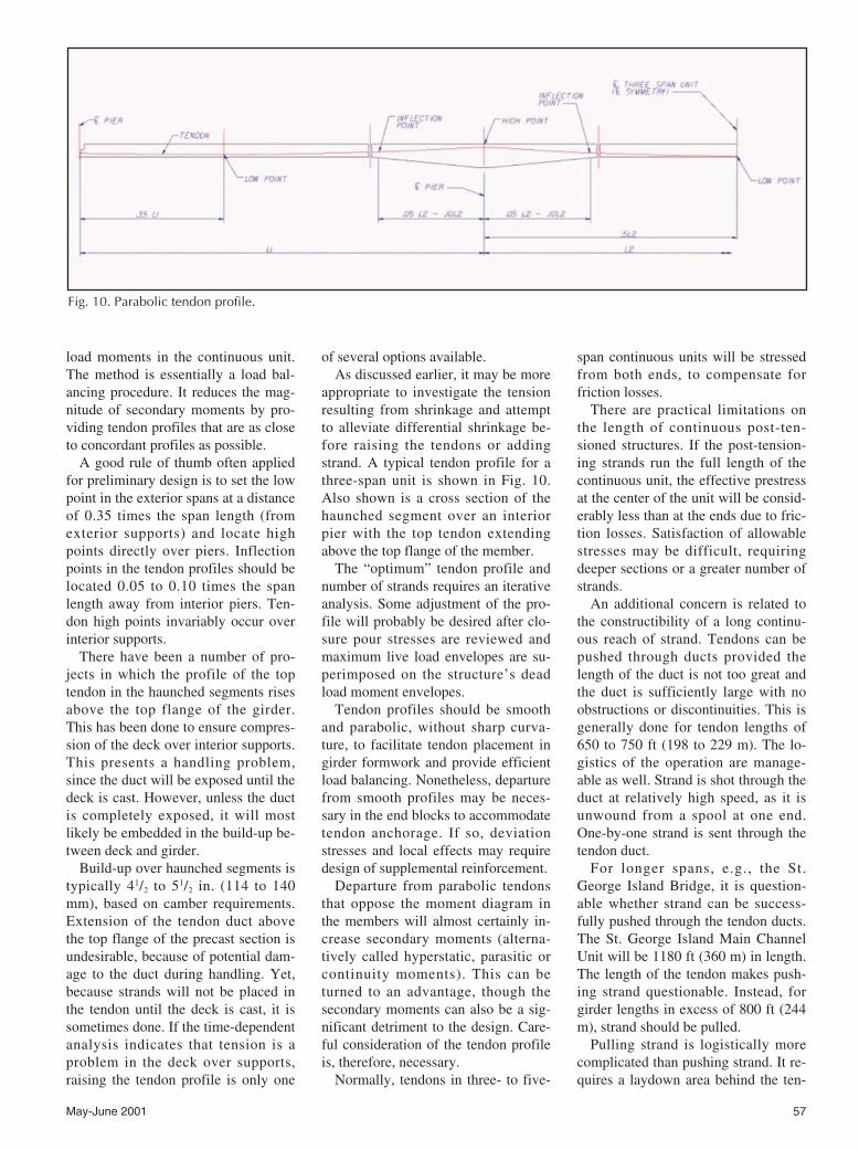
A good rule of thumb often appliedfor preliminary design is to set the lowpoint in the exterior spans at a distanceof 0.35 times the span length (fromexterior supports) and locate highpoints directly over piers. Inflectionpoints in the tendon profiles should belocated 0.05 to 0.10 times the spanlength away from interior piers. Ten-don high points invariably occur overinterior supports.
There have been a number of pro-jects in which the profile of the toptendon in the haunched segments risesabove the top flange of the girder.This has been done to ensure compres-sion of the deck over interior supports.This presents a handling problem,since the duct will be exposed until thedeck is cast. However, unless the ductis completely exposed, it will mostlikely be embedded in the build-up be-tween deck and girder.
Build-up over haunched segments istypically 41/2 to 51/2 in. (114 to 140mm), based on camber requirements.Extension of the tendon duct abovethe top flange of the precast section isundesirable, because of potential dam-age to the duct during handling. Yet,because strands will not be placed inthe tendon until the deck is cast, it issometimes done. If the time-dependentanalysis indicates that tension is aproblem in the deck over supports,raising the tendon profile is only one
of several options available. As discussed earlier, it may be more
appropriate to investigate the tensionresulting from shrinkage and attemptto alleviate differential shrinkage be-fore raising the tendons or addingstrand. A typical tendon profile for athree-span unit is shown in Fig. 10.Also shown is a cross section of thehaunched segment over an interiorpier with the top tendon extendingabove the top flange of the member.
The “optimum” tendon profile andnumber of strands requires an iterativeanalysis. Some adjustment of the pro-file will probably be desired after clo-sure pour stresses are reviewed andmaximum live load envelopes are su-perimposed on the structure’s deadload moment envelopes.
Tendon profiles should be smoothand parabolic, without sharp curva-ture, to facilitate tendon placement ingirder formwork and provide efficientload balancing. Nonetheless, departurefrom smooth profiles may be neces-sary in the end blocks to accommodatetendon anchorage. If so, deviationstresses and local effects may requiredesign of supplemental reinforcement.
Departure from parabolic tendonsthat oppose the moment diagram inthe members will almost certainly in-crease secondary moments (alterna-tively called hyperstatic, parasitic orcontinuity moments). This can beturned to an advantage, though thesecondary moments can also be a sig-nificant detriment to the design. Care-ful consideration of the tendon profileis, therefore, necessary.
Normally, tendons in three- to five-
span continuous units will be stressedfrom both ends, to compensate forfriction losses.
There are practical limitations onthe length of continuous post-ten-sioned structures. If the post-tension-ing strands run the full length of thecontinuous unit, the effective prestressat the center of the unit will be consid-erably less than at the ends due to fric-tion losses. Satisfaction of allowablestresses may be difficult, requiringdeeper sections or a greater number ofstrands.
An additional concern is related tothe constructibility of a long continu-ous reach of strand. Tendons can bepushed through ducts provided thelength of the duct is not too great andthe duct is sufficiently large with noobstructions or discontinuities. This isgenerally done for tendon lengths of650 to 750 ft (198 to 229 m). The lo-gistics of the operation are manage-able as well. Strand is shot through theduct at relatively high speed, as it isunwound from a spool at one end.One-by-one strand is sent through thetendon duct.
For longer spans, e.g., the St.George Island Bridge, it is question-able whether strand can be success-fully pushed through the tendon ducts.The St. George Island Main ChannelUnit will be 1180 ft (360 m) in length.The length of the tendon makes push-ing strand questionable. Instead, forgirder lengths in excess of 800 ft (244m), strand should be pulled.
Pulling strand is logistically morecomplicated than pushing strand. It re-quires a laydown area behind the ten-
Fig. 10. Parabolic tendon profile.
58 PCI JOURNAL
don duct so that strand can be bun-dled. When tendons are pulled, allstrand is pulled together. The lay-down area will necessarily be 1180 ft(360 m) long on St. George. The lay-down area is the deck behind thechannel unit, on the approach spans.It must be protected from spalling dueto pulling of the strand across thedeck, and the strand must be similarlyprotected. Consequently, it is a morecostly operation than pushing strand.
At some point, the length of thestructure will make a long continuousrun of post-tensioning strand imprac-tical. To overcome the need to pushor pull strand long distances for con-tinuous tendons, and to compensatefor the loss of prestress due to frictionlosses, it appears feasible to proposeoverlapping tendons, with tendon an-chorages at blisters located left andright of closure pours.
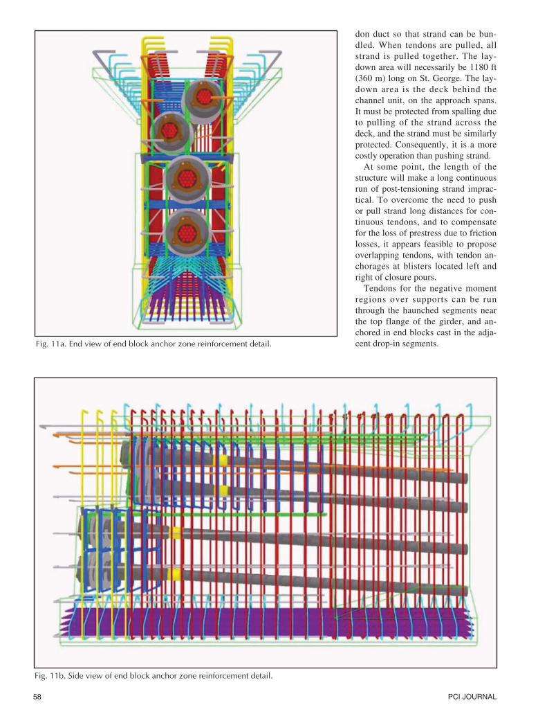
Tendons for the negative momentregions over supports can be runthrough the haunched segments nearthe top flange of the girder, and an-chored in end blocks cast in the adja-cent drop-in segments. Fig. 11a. End view of end block anchor zone reinforcement detail.
Fig. 11b. Side view of end block anchor zone reinforcement detail.
May-June 2001 59
Conversely, tendons for positivemoment in the drop-in and end seg-ments can be run through the bottomof drop-ins and anchored to endblocks cast in the adjacent haunchedsegments. In this manner, a continu-
ous structure of indefinite length maybe constructed in the future. A moreeconomical variation of this themewould have a tendon continuous overtwo or three spans, then anchored inthe adjacent drop-in unit. These varia-
tions of the spliced bulb-tee design ap-pear to be untried. The method wouldmost likely produce significant sec-ondary moments. A future project maywarrant giving this approach closerscrutiny.
Fig. 12a. Erection sequence schematic (Stages 1 to 3).
Fig. 12b. Erection sequence schematic (Stages 4 to 7).
60 PCI JOURNAL
End Block Design and Details
The design of end segment anchorzones can have a significant impact onthe erection sequence used to con-struct the bridge. As indicated earlier,there are three generic end block de-tails that have been used for the post-tensioned spliced bulb-tee system.
There are essential design aspectscommon to all end block regions.These include both local and generalanchorage zones, with correspondingstress concentrations that must be con-sidered. And in each case the designof the anchor zone must consider theeffect that staged post-tensioning hason stress patterns.
AASHTO has incorporated exten-sive provisions for the design of an-chor zones into the LRFD Code, andthe provisions of Section 5.10.9 areapplicable to anchor zone design. Theequations of Section 5.10.9.6 are, in
general, most appropriate to end blockdesign for post-tensioned bulb-teegirders similar to the FBT-78. Theseare the equations the author has em-ployed to size anchor zone bursting re-inforcement and check compressivestresses.
Note that because tendons arestressed sequentially (i.e., Tendon 1,then Tendon 2, etc.), reinforcementmust be appropriate for each stage ofloading. For example, though the netjacking force to be considered whenonly one or two tendons are stressed ismuch lower than the total jackingforce, the eccentricity of the tendonswill lead to different bursting stresses,and equally important, to differentcentroids of the net bursting force.
The bursting stresses for one or twotendons at a large eccentricity fromthe centroid of the bulb tee may behigher than the bursting stresses whenthe last tendon is stressed. Since all
tendons act together, they may not beeffectively smoothed out over such ashort distance. Edge tension forcesmust be examined sequentially aswell.
In addition to compressive, burstingand edge tension stresses, there areshear forces and radial forces on devi-ated tendons. These must be calcu-lated independently and superim-posed. Radial forces on deviatedtendons can be assessed using themethod of equivalent external loads.The curvature of the tendon leads toradial forces on the concrete that canbe determined from the prestressingprofile.
For example, a circular profile leadsto a uniform distributed load of P/Ralong the tendon, where P is the ten-don prestress force, and R is the radiusof curvature. Similar equations applyto parabolic and “kinked” tendons.
It should be cautioned that all of
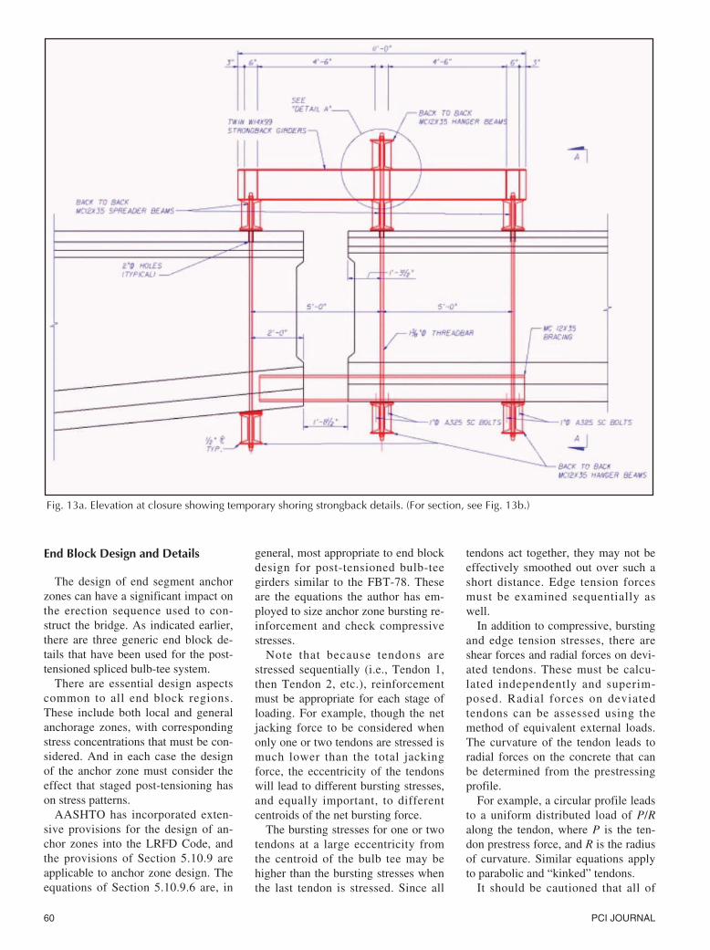
Fig. 13a. Elevation at closure showing temporary shoring strongback details. (For section, see Fig. 13b.)
May-June 2001 61
these methods are approximate andthat actual stress distributions withinanchor zones are complex and nonlin-ear. Superposition of each action is apractical simplification. It is recom-mended that the engineer designingend block regions back up his or herdesign with a suitable strut-and-tiemodel, and in the case of very compli-cated or unusual end blocks, perform afinite element analysis to supplementany approximate equations used.
One further consideration should benoted for end block regions where alltendons terminate at the top of thegirder. There will be stresses in theconcrete due to the abrupt change incompression at a tendon anchor. Theconcrete immediately behind the ten-don anchorage may not be com-pressed, while the concrete in front ofthe anchorage experiences a consider-able compressive stress. The stress andstrain gradients between these two re-gions may result in tensile cracking.
This type of anchorage merits spe-
cial consideration and is a good candi-date for supplemental strut-and-tiemodeling or finite element analyses.The equations of AASHTO Section9.10.9.6 should not be literally appliedwhen the tendon anchorage terminateson the top of the girders. Fig. 11 pro-vides three-dimensional isometrics ofend block reinforcement details. Theseisometric views are sometimes re-quired to verify that potential reinforc-ing bar conflicts have been adequatelyconsidered.
Tendon Grouting Considerations
Tendon grouting has recently re-ceived considerable attention inFlorida. Grouting is the operation usedto bond tendons to the precast mem-bers and provide corrosion protectionto the prestressed strands. Typically, aneat cement grout has been used,sometimes with an aluminum powderadditive to provide some expansiveproperties. (Note that aluminum pow-
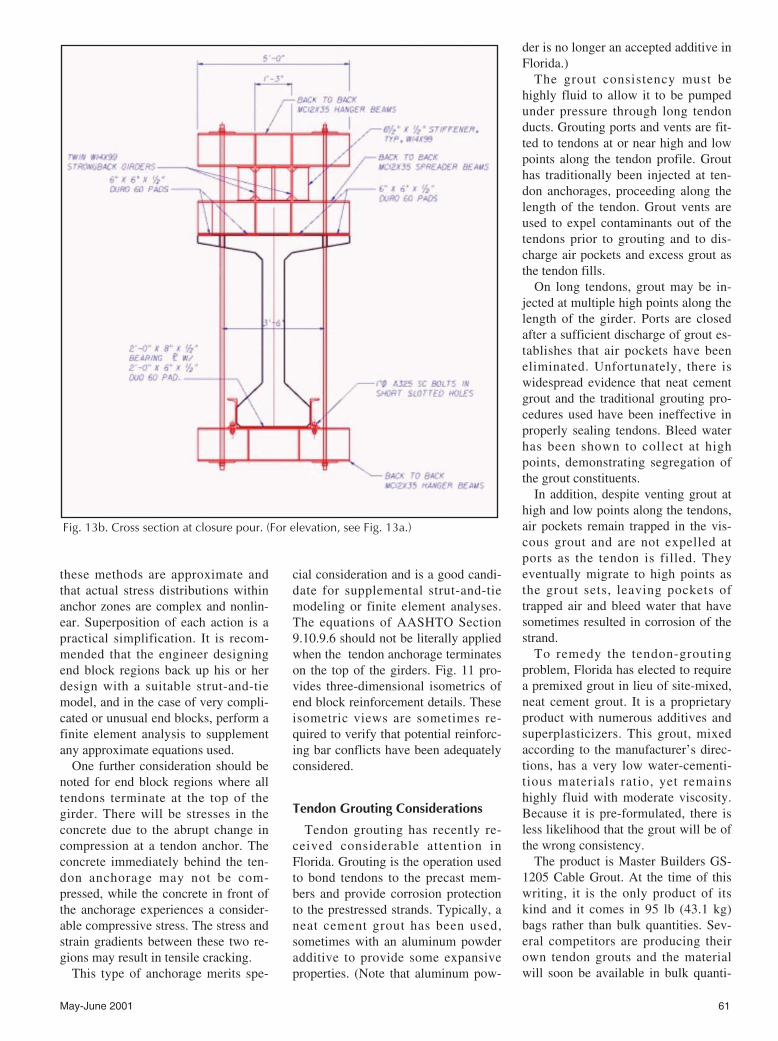
Fig. 13b. Cross section at closure pour. (For elevation, see Fig. 13a.)
der is no longer an accepted additive inFlorida.)
The grout consistency must behighly fluid to allow it to be pumpedunder pressure through long tendonducts. Grouting ports and vents are fit-ted to tendons at or near high and lowpoints along the tendon profile. Grouthas traditionally been injected at ten-don anchorages, proceeding along thelength of the tendon. Grout vents areused to expel contaminants out of thetendons prior to grouting and to dis-charge air pockets and excess grout asthe tendon fills.
On long tendons, grout may be in-jected at multiple high points along thelength of the girder. Ports are closedafter a sufficient discharge of grout es-tablishes that air pockets have beeneliminated. Unfortunately, there iswidespread evidence that neat cementgrout and the traditional grouting pro-cedures used have been ineffective inproperly sealing tendons. Bleed waterhas been shown to collect at highpoints, demonstrating segregation ofthe grout constituents.
In addition, despite venting grout athigh and low points along the tendons,air pockets remain trapped in the vis-cous grout and are not expelled atports as the tendon is filled. Theyeventually migrate to high points asthe grout sets, leaving pockets oftrapped air and bleed water that havesometimes resulted in corrosion of thestrand.
To remedy the tendon-groutingproblem, Florida has elected to requirea premixed grout in lieu of site-mixed,neat cement grout. It is a proprietaryproduct with numerous additives andsuperplasticizers. This grout, mixedaccording to the manufacturer’s direc-tions, has a very low water-cementi-tious materials ratio, yet remainshighly fluid with moderate viscosity.Because it is pre-formulated, there isless likelihood that the grout will be ofthe wrong consistency.
The product is Master Builders GS-1205 Cable Grout. At the time of thiswriting, it is the only product of itskind and it comes in 95 lb (43.1 kg)bags rather than bulk quantities. Sev-eral competitors are producing theirown tendon grouts and the materialwill soon be available in bulk quanti-
62 PCI JOURNAL
based on the simplicity of the design,reliability, and relatively low cost. Thedesign of standard reinforced neo-prene pads and reinforced pads withcomposite slide bearing assemblies iscovered in detail in Section 14 of theLRFD Code. These provisions willnot be reiterated here. But there is onedesign issue that merits discussion,since it is a function of the structuralsystem used, and not the pad design.
Reinforced neoprene pads used onlong continuous post-tensioned struc-tures will be subjected to considerabletranslation due to elastic shorteningduring the construction of the unit,thermal movement, and later due totime-dependent creep and shrinkage ofthe girders. All of these movementsare additive. It may not be practical toprovide a pad that is sized to accom-modate the entire projected pad dis-placement.
At the ends of the unit, slide bear-ings must be used because of the mag-nitude of elastic and long-term short-ening. But use of slide bearings for theinterior piers of the unit will not pro-vide the stability required of the sys-tem to resist nominal wind and/orminor seismic events. It is best to pro-
vide reinforced pads with shearstrength sufficient to absorb theseloads. However, in so doing, the padthickness may become inordinatelylarge, based on anticipated longitudi-nal movement.
On the St. George Island Bridge, theinterior haunched segments bear onneoprene pads. After first-stage post-tensioning, the bearing pads will haveaccumulated 21/2 to 3 in. (64 to 76mm) of longitudinal deformation. Ad-ditional longitudinal displacement dueto elastic shortening, thermal contrac-tion, creep, and shrinkage will lead toexcessive deformation of the pad.Therefore, stress relief of the pads isspecified.
Haunched segments will be liftedoff their pads to relieve the longitudi-nal deformation. Subsequent creepand shrinkage deformation will thenbe well within the pad design parame-ters. Lifting the haunched segments isaccommodated using the temporaryshoring jacks already in place to facili-tate erection of the segments.
Temporary shoring, though gener-ally not designed by the engineer ofrecord, has to be considered by the en-gineer. The sequence of erection plans
ties from several manufacturers. In theinterim, it will be a fairly expensiveproduct.
In addition to the use of a premixedspecially formulated cable grout,Florida has drafted stringent criteriafor tendon grouting operations. It willno longer be sufficient to grout fromhigh points only. Grout must be in-jected from both low and high pointsand in both directions – left to rightthen right to left.
This procedure is intended to ensurethat tendon ducts are completely filledand all air pockets are expelled duringthe grouting process. It is evident thattendon grouting will no longer betaken lightly and that quality controlwill be much tighter. Costs will reflectthe stringent material and executionrequirements, as well as higher qualitycontrol standards.
Bearing Design Considerations
Pot bearings and reinforced neo-prene bearings have been used forcontinuous precast, post-tensionedstructures. On both the Wonderwoodand St. George Island Bridges, rein-forced neoprene pads were chosen
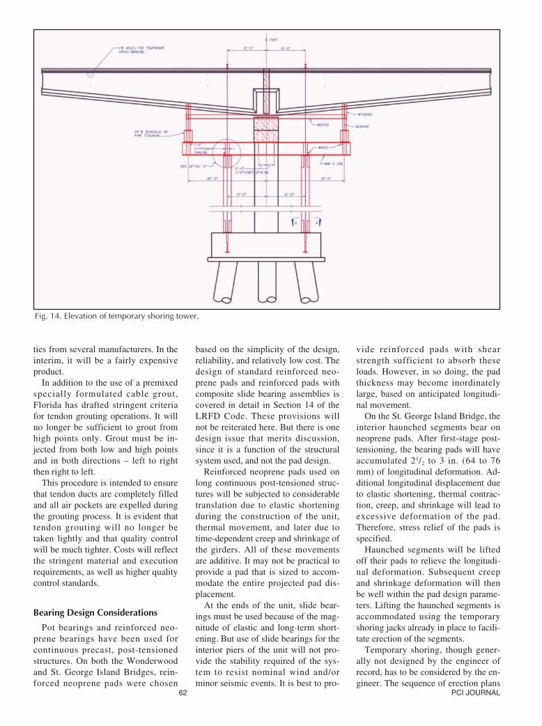
Fig. 14. Elevation of temporary shoring tower.
May-June 2001 63
must accompany the design docu-ments, since the structural system isincrementally constructed, and theerection sequence and shoring detailsdictate the stresses that are ultimatelylocked into the structure. With ade-quate forethought, shoring towers canbe designed to provide platforms forinstallation and dismantlement of di-aphragm formwork and cross bracing,or stress relief in bearings.
Sequence of Erection Drawings
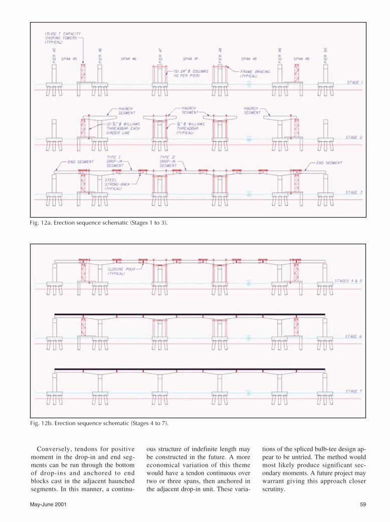
The stress in a segmental structuremust be calculated for each stage oferection and accumulated for final de-termination of the service life stresses.The sequence of construction is, there-fore, an integral part of the design andconstruction, and must be included inthe contract documents. For a post-tensioned bulb-tee system, the se-quence of erection must include pierconstruction, temporary shoring towererection and placement of haunched,end, and drop-in segments.
A suggested sequence of erectionfor a five-span structure is shown inFig. 12. This erection sequence wasprovided in contract documents for the
St. George Island Project. The tempo-rary shoring details have a significanteffect on the construction stresses inthe structure. Strongback details,tower details, segment weights andconstruction loads must be developedin order to tabulate erection loads forthe erection sequence plans.
Temporary Shoring
The primary components of the tem-porary shoring for a spliced bulb-teesystem are the strongbacks that sus-pend end and drop-in segments off ofhaunched segments, and towers usedto support and stabilize the haunchedsegments. Strongbacks are fixed toend and drop-in segments, then easedonto haunched segments and securedto the haunched segments with high-strength threadbar. Along with strong-backs, web clamps are secured acrossclosure pours to prevent girder roll.
All girder segments must be detailedto accommodate strongbacks usedduring erection of the girders. Strong-back tie-downs have typically beendesigned to extend from holes castinto the top flange of bulb tees. In ad-dition, the engineer should consider
strongback details to accommodateshear stirrups that protrude through thetop flanges of girders.
Several incidents have occurred be-cause the design and installation ofstrongbacks were not carefully consid-ered. On at least one project, thestrongback bearing pressure on thebulb-tee flange caused the top flangesto crack. Bearing between strongbacksand girders should be concentrated onthe area over girder webs.
On another project, web clamps hadnot been fastened tightly to thehaunched segments and the drop-insegments slowly but progressivelytwisted until the strongbacks failedand the girders fell. Should there beany sweep in the girders, torsion maycause the girders to roll. The design ofstrongbacks cannot be neglected. Typ-ical strongback details are shown inFig. 13.
There are several variations to thedesign of shoring towers. For a three-span unit, two towers are generallyconstructed, one under each closurepour in the exterior spans. Afterhaunched segments are set on CIPpiers, the outboard end of the seg-ments are tied down to the shoring
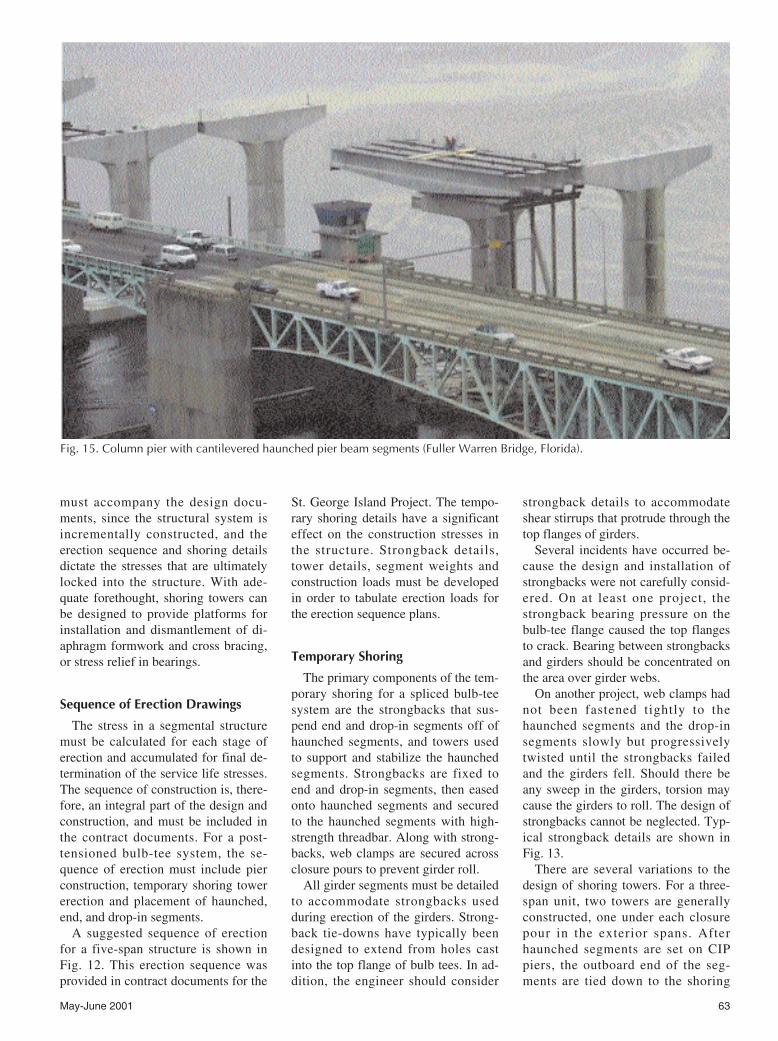
Fig. 15. Column pier with cantilevered haunched pier beam segments (Fuller Warren Bridge, Florida).
64 PCI JOURNAL
towers. End segments are then erectedand eased onto haunched segmentsusing strongback attachments, or setdirectly onto the towers adjacent to thehaunches.
There is an advantage to setting endsegments directly onto the haunches.They provide resistance to upliftwhich otherwise must be provided bytie-downs. Uplift occurs when thedrop-in segments are suspended fromthe opposite end of the haunched seg-ments. The loading of each stage isconsidered in the design of shoringtowers and must be noted on the erec-tion sequence drawings.
If the CIP piers supporting thehaunched segments are founded onpile caps of sufficient size, it is feasi-ble to support temporary towers on thepile caps. There is a definite advantageto using the pile cap for the base of thetemporary towers. Towers locatedunder closure pours generally requiretemporary pile foundations.
The towers and foundations cannotbe removed until construction of thesuperstructure is complete, and oncethe superstructure is in place over thetemporary piling, it is difficult to sal-vage the shoring. On two recent bulb-tee projects, the pile caps have beenused to support shoring towers. TheSt. George Island Bridge is one ofthese projects. The typical shoringtower design for St. George Island isshown in Fig. 14.
Various sequences of the erection ofa bridge superstructure are shown inFigs. 15 through 20.
Temporary shoring is critical for thesafe erection of girders and can be acostly bid item. Therefore, it warrantscareful consideration and forethought.
CONCLUDING REMARKS
Continuous composite post-ten-sioned bulb-tee girder systems haveproven to provide a very adaptablestructural system for intermediate andlong-span bridge construction. Futureimprovements to the system promiseeven greater adaptability, and the pos-sibility that longer spans may bebridged. The discussion of design andconstruction considerations in thispaper provides some background onthe problems that have been encoun-
Fig. 16. Drop-in segmentfabrication atthe MooreHavenBridge,OkeechobeeWaterway,Florida.
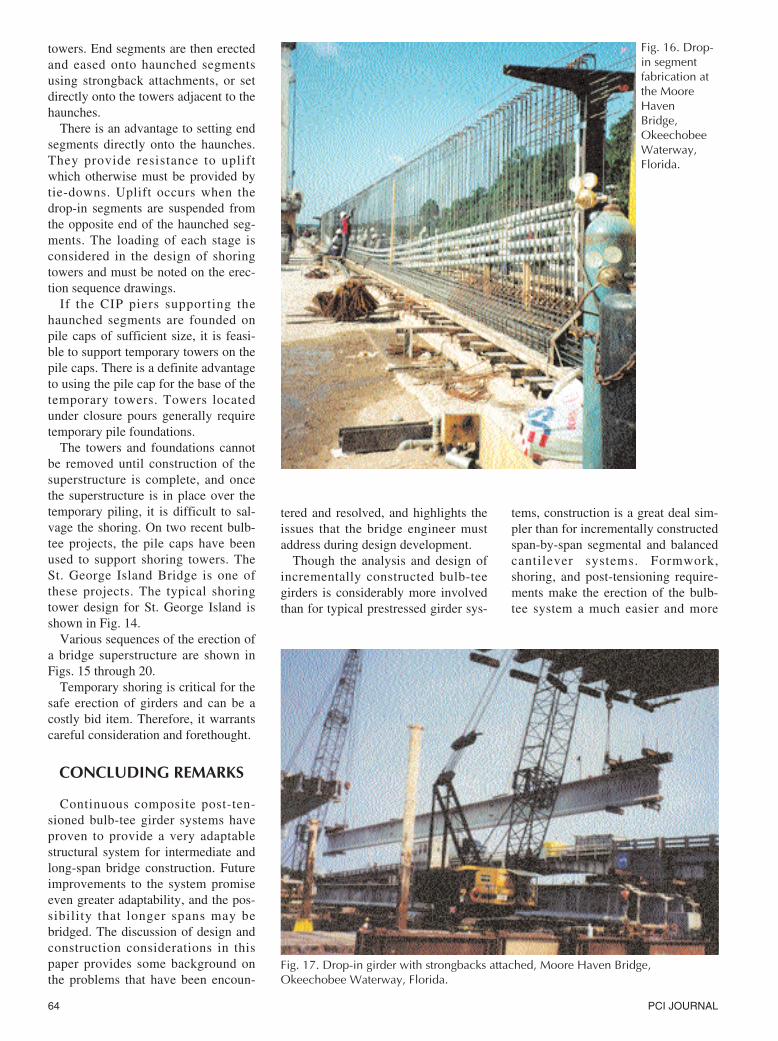
Fig. 17. Drop-in girder with strongbacks attached, Moore Haven Bridge, Okeechobee Waterway, Florida.
tered and resolved, and highlights theissues that the bridge engineer mustaddress during design development.
Though the analysis and design ofincrementally constructed bulb-teegirders is considerably more involvedthan for typical prestressed girder sys-
tems, construction is a great deal sim-pler than for incrementally constructedspan-by-span segmental and balancedcantilever systems. Formwork,shoring, and post-tensioning require-ments make the erection of the bulb-tee system a much easier and more
May-June 2001 65
cost-effective structural system thanspan-by-span and balanced cantileverconstruction.
The AASHTO Code does not referto this type of construction directly,but adherence to the allowable stressprovisions for prestressed concretemembers is the current standard fordesign. The author hopes that futurecode revisions will address this typeof system directly. Guidelines for con-struction loads, creep and shrinkageparameters (in the absence of labora-tory testing), and minimum reinforce-ment requirements or allowablestresses in the deck should be dis-cussed. The construction schedule as-sumed in design should also be re-quired on the Sequence of ErectionDrawings.
A final note regarding post-ten-sioned girder systems: there are anumber of commercially availableprograms for analysis of incrementallyconstructed structures. These includeADAPT, BD-II, TANGO, and others.Each has advantages and disadvan-tages. It is recommended that the en-gineer become very familiar with theprogram used for time-dependent
Fig. 19. Strongback installation at closure pour, Moore Haven Bridge, OkeechobeeWaterway, Florida.
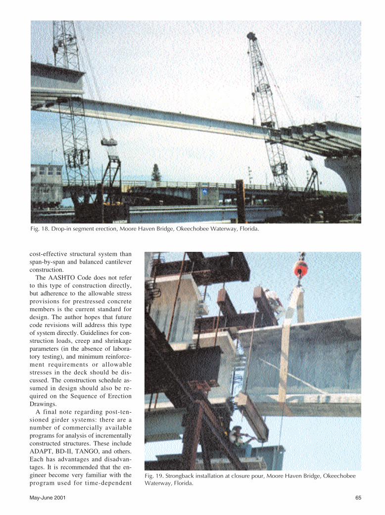
Fig. 18. Drop-in segment erection, Moore Haven Bridge, Okeechobee Waterway, Florida.
66 PCI JOURNAL
analysis of composite structures. Sim-ple structural systems should be ana-lyzed first and compared with knownresults. It is difficult to gauge the ac-curacy and reliability of the results ofa complex analysis if the first problemsolved is the design of a two-stagedpost-tensioned composite system.
ACKNOWLEDGMENTThe author wishes to express his ap-
preciation to Henry Bollmann of theFlorida Department of Transportationfor his review of this paper. Mr. Boll-mann provided valuable guidance andperspective on the content and clarity
of the work. However, the author ac-cepts responsibility for any inaccura-cies that may be found in the article.
REFERENCES1. Janssen, Hubert H., and Spaans, Leo,
“Bids Reveal Economy of PrecastPost-Tensioned Girders on Bridge Pro-ject,” PCI JOURNAL, V. 37, No. 1,January-February 1992, pp. 86-87.
2. Ficenec, Joseph A., Kneip, Steven D.,and Tadros, Maher K., “A New Con-tinuous Precast Concrete Bridge Sys-tem,” IBC Paper Number IBC-93-26,International Building Code, FallsChurch, VA, June 1993.
3. Alami, Bijan O., “Design Fundamen-
tals of Segmentally ConstructedBridges with Particular Reference toAASHTO LRFD Method,” AmericanAssociation of State Highway Offi-cials, Washington, DC, June 1997.
4. Abdel-Karim, Ahmad M., and Tadros,Maher K., “State of the Art of Pre-cast/Prestressed Concrete Spliced I-Girder Bridges,” for the PCI Commit-tee on Bridges, Precast/PrestressedConcrete Institute, Chicago, IL, Sec-ond Printing, 1995, 134 pp.
5. Caroland, William B., Depp, David,Janssen, Hubert H., and Spaans, Leo,“Spliced Segmental Prestressed Con-crete I-Beams for Shelby CreekBridge,” PCI JOURNAL, V. 37, No.5, September-October 1992, pp. 22-33.
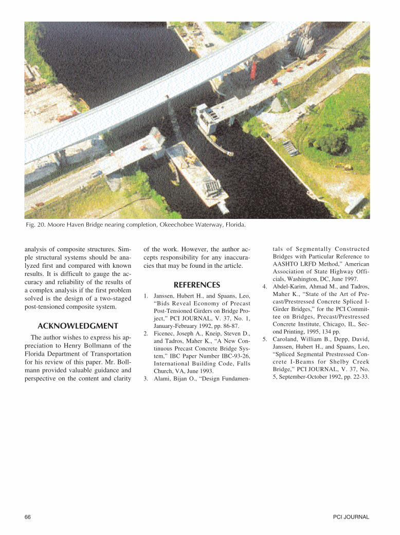
Fig. 20. Moore Haven Bridge nearing completion, Okeechobee Waterway, Florida.