Embed Size (px)
Citation preview
Design and Configuration of IPS,IDS and SIEM in IndustrialControl Systems
CERT DE SEGURIDADE INDUSTRIA
MINISTERIODEL INTERIOR
GOBIERNODE ESPAÑA
MINISTERIODE ENERGÍA, TURISMOY AGENDA DIGITAL
GOBIERNODE ESPAÑA

IPS, IDS and SIEM Design and Configuration in Industrial Control Systems Page 2 of 56
November 2017
CERTSI_GUIA_SCI_004_ConfiguracionIPSIDSySIEM_2017_v1
This publication belongs to INCIBE (Spanish National Cybersecurity Institute) and is licensed under a Creative Commons Attribution-Noncommercial 3.0 Spain License. For this reason, it is permitted to copy, distribute and communicate this work publicly under the following conditions:
• Acknowledgement. The content of this report may be reproduced in part or in full by third parties, with the appropriate acknowledgement and making express reference to INCIBE or CERTSI and its website: http://www.incibe.es. Under no circumstances shall said acknowledgement imply that INCIBE supports said third party or supports the use they make of this work.
• Non-commercial Use. The original material and the derived works may be distributed, copied and exhibited provided their use does not have a commercial purpose.
By reusing or distributing the work, the terms of the license of this work must be made clear. Some of these conditions may not apply if permission is obtained from CERTSI as owner of the authorship rights. Full text of the license: http://creativecommons.org/licenses/by-nc-sa/3.0/es/
IPS, IDS and SIEM Design and Configuration in Industrial Control Systems Page 3 of 56
INDEX
INDEX .................................................................................................................... 3
INDEX OF GRAPHICS .......................................................................................... 4
INDEX OF TABLES ............................................................................................... 5
1 ABOUT THIS GUIDE ...................................................................................... 6
2 INTRODUCTION ............................................................................................. 7
3 STRUCTURE OF THIS DOCUMENT .............................................................. 8
4 ROLL-OUT RECOMMENDATIONS ................................................................ 9
4.1 Introduction ............................................................................................... 9
4.2 System-control base architecture .............................................................. 9
4.3 Security architectures for control systems ............................................... 11
5 INSTALLATION MANUAL ............................................................................ 16
5.1 Introduction ............................................................................................. 16
5.2 Design of laboratory architecture ............................................................ 16
5.3 Network design ....................................................................................... 17
Bridge Creation ............................................................................................................. 17
5.4 Installation of Snort.................................................................................. 17
Dependencies ............................................................................................................... 18
Configuration ................................................................................................................ 18
Barnyard ....................................................................................................................... 19
5.5 Collection and analysis of alerts and events ........................................... 20
Dependencies ............................................................................................................... 21
Snorby installation and configuration ........................................................................... 21
6 CONCLUSIONS ............................................................................................ 24
ANNEX 1. FUNDAMENTALS OF MONITORING TECHNOLOGY ................... 25
ANNEX 1.1. DEFINITIONS ............................................................................ 25
ANNEX 1.1.1. IDS .................................................................................................................... 25
ANNEX 1.1.2. IPS .................................................................................................................... 25
ANNEX 1.1.3. SIEM ................................................................................................................. 25
ANNEX 1.2. IDS ............................................................................................. 25
ANNEX 1.2.1. Tasks of an IDS ................................................................................................ 26
ANNEX 1.2.2. Types of IDS ..................................................................................................... 26
ANNEX 1.2.3. Focus-based ..................................................................................................... 27
ANNEX 1.2.4. Based on the origin of the data ........................................................................ 28
ANNEX 1.2.5. Structure-based ................................................................................................ 29
ANNEX 1.3. IPS ............................................................................................. 31
ANNEX 1.3.1. The IPS as evolution of the IDS ....................................................................... 32
ANNEX 1.3.2. Types of IPS ..................................................................................................... 33
ANNEX 1.3.3. Network-based IPS (NIPS) vs host-based IPA (HIPS) .................................... 33
IPS, IDS and SIEM Design and Configuration in Industrial Control Systems Page 4 of 56
ANNEX 1.3.4. IPS categories and their evolution .................................................................... 33
ANNEX 1.3.5. Inline IPS .......................................................................................................... 34
ANNEX 1.4. SIEM .......................................................................................... 35
ANNEX 1.4.1. Real time detection capacity ............................................................................ 36
ANNEX 1.4.2. Event Archive Management ............................................................................. 36
ANNEX 1.4.3. Understanding an SIEM ................................................................................... 36
ANNEX 1.4.4. Implementation of SIEMs in industrial networks............................................... 37
ANNEX 2. TECHNOLOGICAL SOLUTIONS ..................................................... 41
ANNEX 2.1. IDS/IPS Solutions ....................................................................... 41
ANNEX 2.1.1. Snort ................................................................................................................. 41
ANNEX 2.1.2. Suricata............................................................................................................. 42
Annex 2.1.3. Bro .................................................................................................................... 43
Annex 2.1.4. OSSEC ............................................................................................................. 44
Annex 2.1.5. Comparison between various IDS/IPS ............................................................. 45
ANNEX 2.2. SIEM Tools ................................................................................. 45
ANNEX 2.2.1. Snorby .............................................................................................................. 45
ANNEX 2.2.2. Sguil .................................................................................................................. 46
ANNEX 2.2.3. Squert ............................................................................................................... 48
ANNEX 2.2.4. ELSA ................................................................................................................. 49
ANNEX 2.2.5. SPLUNK ........................................................................................................... 50
ANNEX 2.3. Security Onion ............................................................................ 51
ANNEX 2.3.1. Principal components ....................................................................................... 52
ANNEX 2.3.2. Overview ........................................................................................................... 53
ANNEX 2.3.3. Implementation ................................................................................................. 53
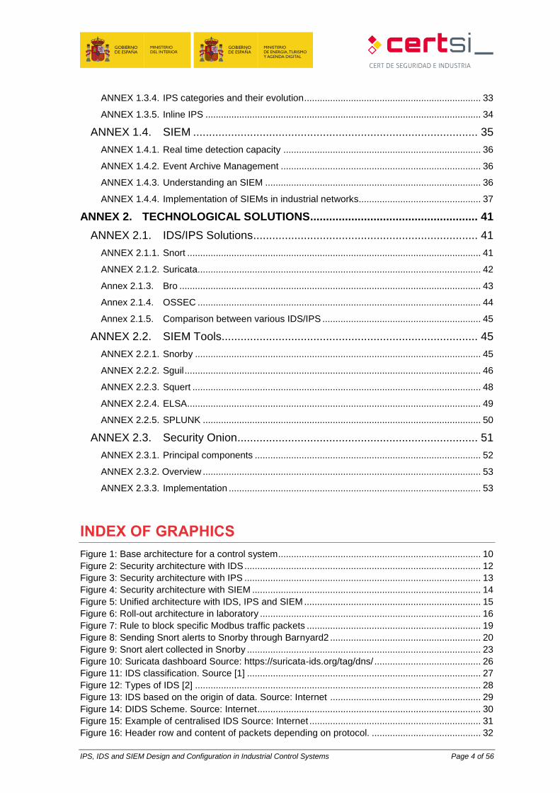
INDEX OF GRAPHICS
Figure 1: Base architecture for a control system .............................................................................. 10 Figure 2: Security architecture with IDS ........................................................................................... 12 Figure 3: Security architecture with IPS ........................................................................................... 13 Figure 4: Security architecture with SIEM ........................................................................................ 14 Figure 5: Unified architecture with IDS, IPS and SIEM .................................................................... 15 Figure 6: Roll-out architecture in laboratory ..................................................................................... 16 Figure 7: Rule to block specific Modbus traffic packets ................................................................... 19 Figure 8: Sending Snort alerts to Snorby through Barnyard2 .......................................................... 20 Figure 9: Snort alert collected in Snorby .......................................................................................... 23 Figure 10: Suricata dashboard Source: https://suricata-ids.org/tag/dns/ ......................................... 26 Figure 11: IDS classification. Source [1] .......................................................................................... 27 Figure 12: Types of IDS [2] .............................................................................................................. 28 Figure 13: IDS based on the origin of data. Source: Internet .......................................................... 29 Figure 14: DIDS Scheme. Source: Internet ...................................................................................... 30 Figure 15: Example of centralised IDS Source: Internet .................................................................. 31 Figure 16: Header row and content of packets depending on protocol. .......................................... 32
IPS, IDS and SIEM Design and Configuration in Industrial Control Systems Page 5 of 56
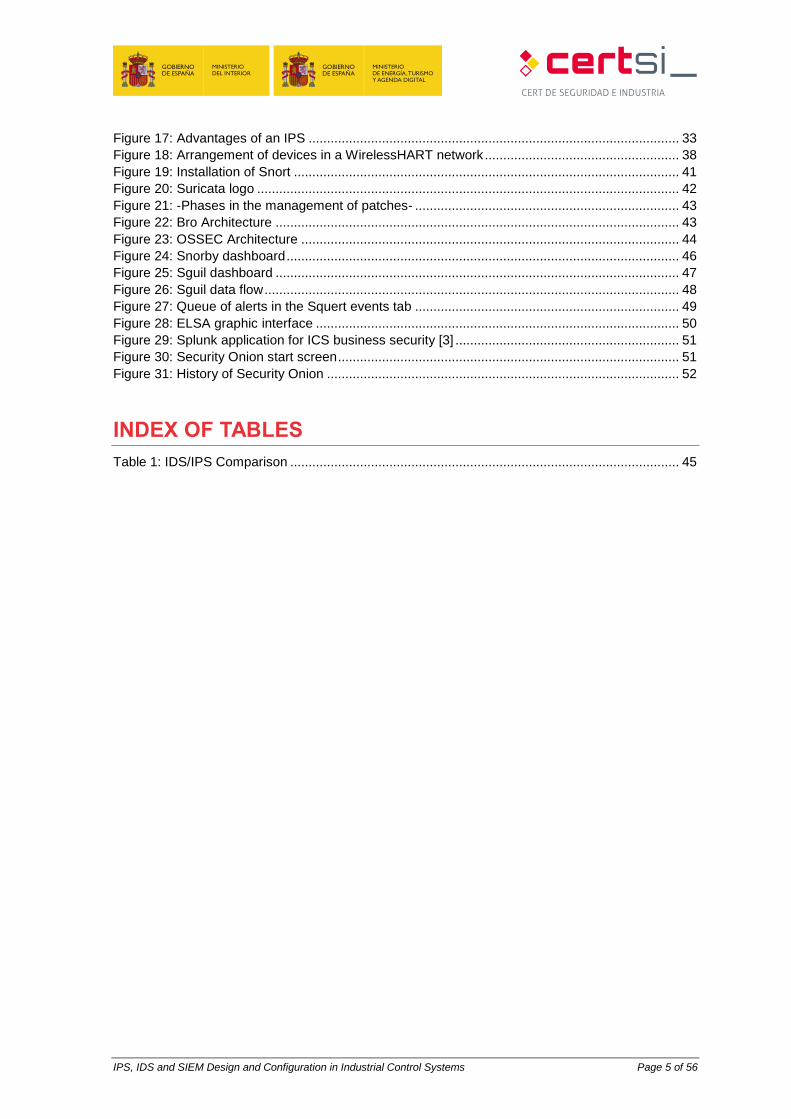
Figure 17: Advantages of an IPS ..................................................................................................... 33 Figure 18: Arrangement of devices in a WirelessHART network ..................................................... 38 Figure 19: Installation of Snort ......................................................................................................... 41 Figure 20: Suricata logo ................................................................................................................... 42 Figure 21: -Phases in the management of patches- ........................................................................ 43 Figure 22: Bro Architecture .............................................................................................................. 43 Figure 23: OSSEC Architecture ....................................................................................................... 44 Figure 24: Snorby dashboard ........................................................................................................... 46 Figure 25: Sguil dashboard .............................................................................................................. 47 Figure 26: Sguil data flow ................................................................................................................. 48 Figure 27: Queue of alerts in the Squert events tab ........................................................................ 49 Figure 28: ELSA graphic interface ................................................................................................... 50 Figure 29: Splunk application for ICS business security [3] ............................................................. 51 Figure 30: Security Onion start screen ............................................................................................. 51 Figure 31: History of Security Onion ................................................................................................ 52
INDEX OF TABLES
Table 1: IDS/IPS Comparison .......................................................................................................... 45

IPS, IDS and SIEM Design and Configuration in Industrial Control Systems Page 6 of 56
1 ABOUT THIS GUIDE
This technical study is a description of the use of intrusion detection and prevention systems
and event collection systems geared towards control systems.
There is also detail on how some of these solutions function and recommendations on the
security to be applied in these technologies.
IPS, IDS and SIEM Design and Configuration in Industrial Control Systems Page 7 of 56
2 INTRODUCTION
At present, there is a close relationship between the information and technology used in
companies. Over time, new technologies have emerged and evolved that allow illegitimate
access via vulnerabilities found in OT networks.
In response to these vulnerabilities, architecture, techniques and systems that detect and
prevent these undue accesses have been developed. So IDSs emerged, with the principal
function of detecting anomalies and undue use (initially intended for the IT world). Current
threats against OT networks ensure that the use of these tools is implemented in industrial
networks, examining in detail the protocols and transmissions that circulate through the
network.
Faced with the difficulty for IDSs of reacting to intrusion alerts, IPSs were then developed,
which would assume responsibility for reacting actively to intrusions detected by the IDS.
Today, the terms IDS and IPS are used interchangeably and the equipment is identical,
changing the way of simple function depending on the type of roll-out and on a number of
parameter configurations.
To advance the defence technology further, SIEM systems emerged, which do not depend
on a single source of information, such as an IDS / IPS. In addition to centralising
information, they are capable of relating (the verb correlate is usually used in this context in
IT and will be used frequently in this document) events from different sources to generate
personalized alerts. These devices will contribute the intelligence necessary to reduce the
number of false positives step-by-step.
There is a certain advantage in using these systems that combine different types of
learnings and management, due to the fact that in industrial networks they usually offer
lower variability than in the world of IT. For this reason, they can prove more effective and
detect a lower number of false positives.
IPS, IDS and SIEM Design and Configuration in Industrial Control Systems Page 8 of 56
3 STRUCTURE OF THIS DOCUMENT
This document includes two technical sections focussed on IDS/IPS and SIEM industrial
and technological control systems and two annexes where the technologies and
applicatives relating to each of the two technical sections are detailed.
In the first technical section (section 4) a network architecture for industrial control systems
in the form of base architecture and, using this, other security architectures and
recommendations for roll-out of a real environment with the security technologies analysed
in this document; the second technical section (section 5) provides precise step-by-step
technical instructions for the installation of an infrastructure that covers the technologies
covered in this document. Specifically, readers are instructed that they may roll out an
IDS/IPS system in Inline mode along with an event monitoring system.
In the annexes, the first part (0) contains definitions, characteristics and advantages of each
of the technologies that form part of the study, not just in the world of IT but also providing
detail at industrial level. The second part (0) numerates and details various security
solutions described that have been tested in the laboratory.

IPS, IDS and SIEM Design and Configuration in Industrial Control Systems Page 9 of 56
4 ROLL-OUT RECOMMENDATIONS
4.1 Introduction
On the following points different types of roll-outs are detailed using technologies described
in this document, IDS/IPS and SIEM. It will be based on a base architecture that will evolve
to reach a complete architecture that contains all the elements necessary to avail of
intrusion detection/prevention system and an event collection and management system.
4.2 System-control base architecture
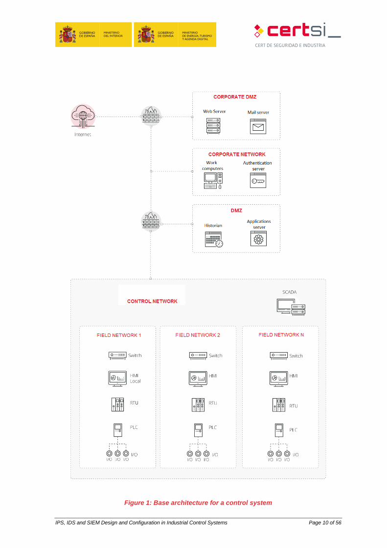
The base architecture selected is based on the proposal contained in Standard IEC 62443
[33]. It defines the different areas associated with the levels into which an industrial control
system is divided.
The base architecture provides segmentation based on firewalls to separate the control and
business areas, with two DMZs for the exchange of information between the two.
The architectures proposed below have security architectures that to ensure
communications and devices located in the control part of the network. The security of the
business area has not been taken into account as part of this study as it lies beyond the
scope.
IPS, IDS and SIEM Design and Configuration in Industrial Control Systems Page 10 of 56
Figure 1: Base architecture for a control system
IPS, IDS and SIEM Design and Configuration in Industrial Control Systems Page 11 of 56
4.3 Security architectures for control systems
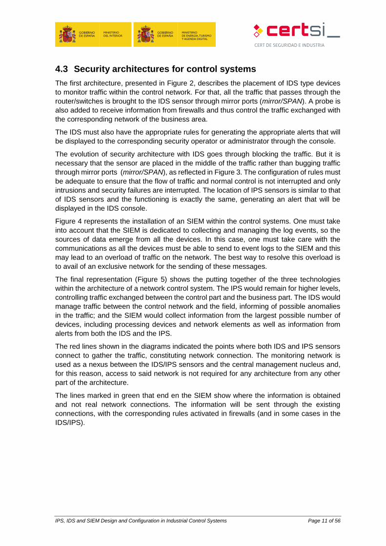
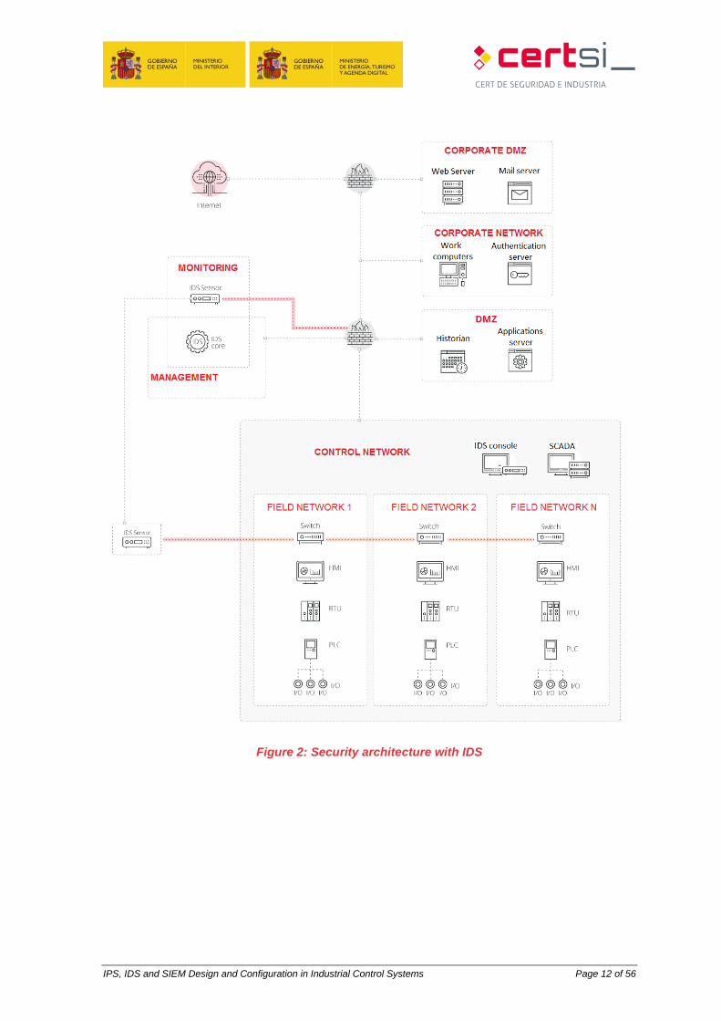
The first architecture, presented in Figure 2, describes the placement of IDS type devices
to monitor traffic within the control network. For that, all the traffic that passes through the
router/switches is brought to the IDS sensor through mirror ports (mirror/SPAN). A probe is
also added to receive information from firewalls and thus control the traffic exchanged with
the corresponding network of the business area.
The IDS must also have the appropriate rules for generating the appropriate alerts that will
be displayed to the corresponding security operator or administrator through the console.
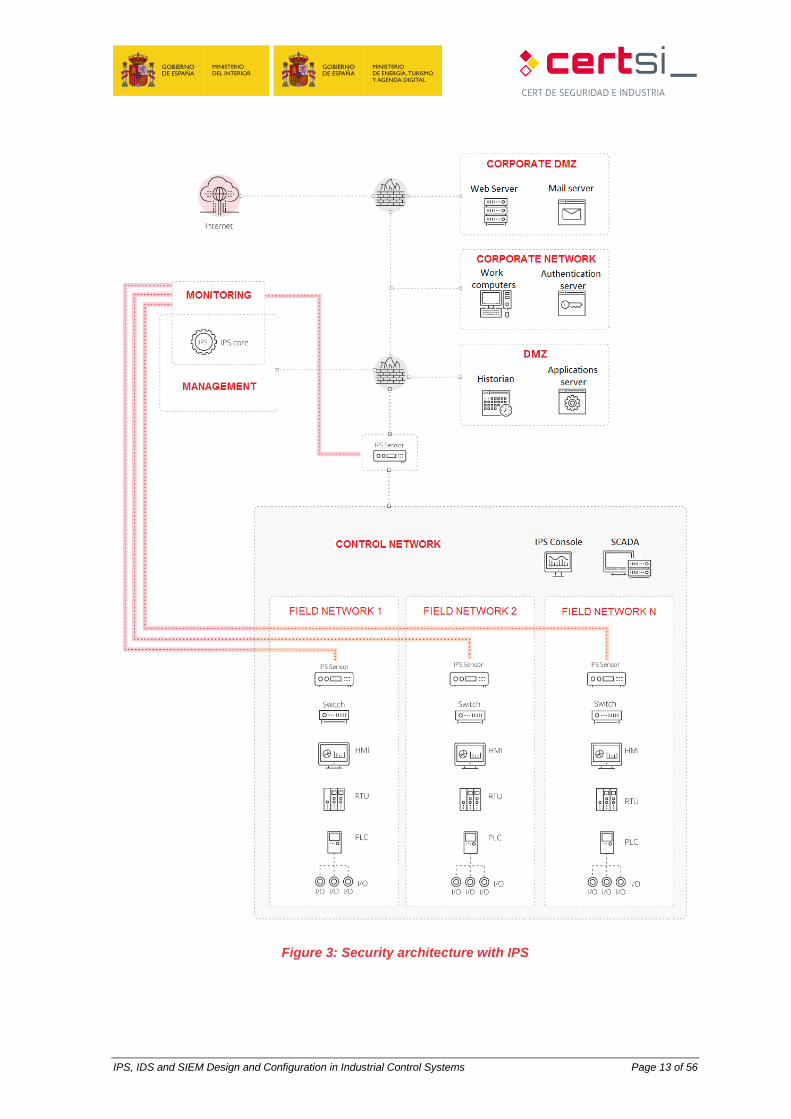
The evolution of security architecture with IDS goes through blocking the traffic. But it is
necessary that the sensor are placed in the middle of the traffic rather than bugging traffic
through mirror ports (mirror/SPAN), as reflected in Figure 3. The configuration of rules must
be adequate to ensure that the flow of traffic and normal control is not interrupted and only
intrusions and security failures are interrupted. The location of IPS sensors is similar to that
of IDS sensors and the functioning is exactly the same, generating an alert that will be
displayed in the IDS console.
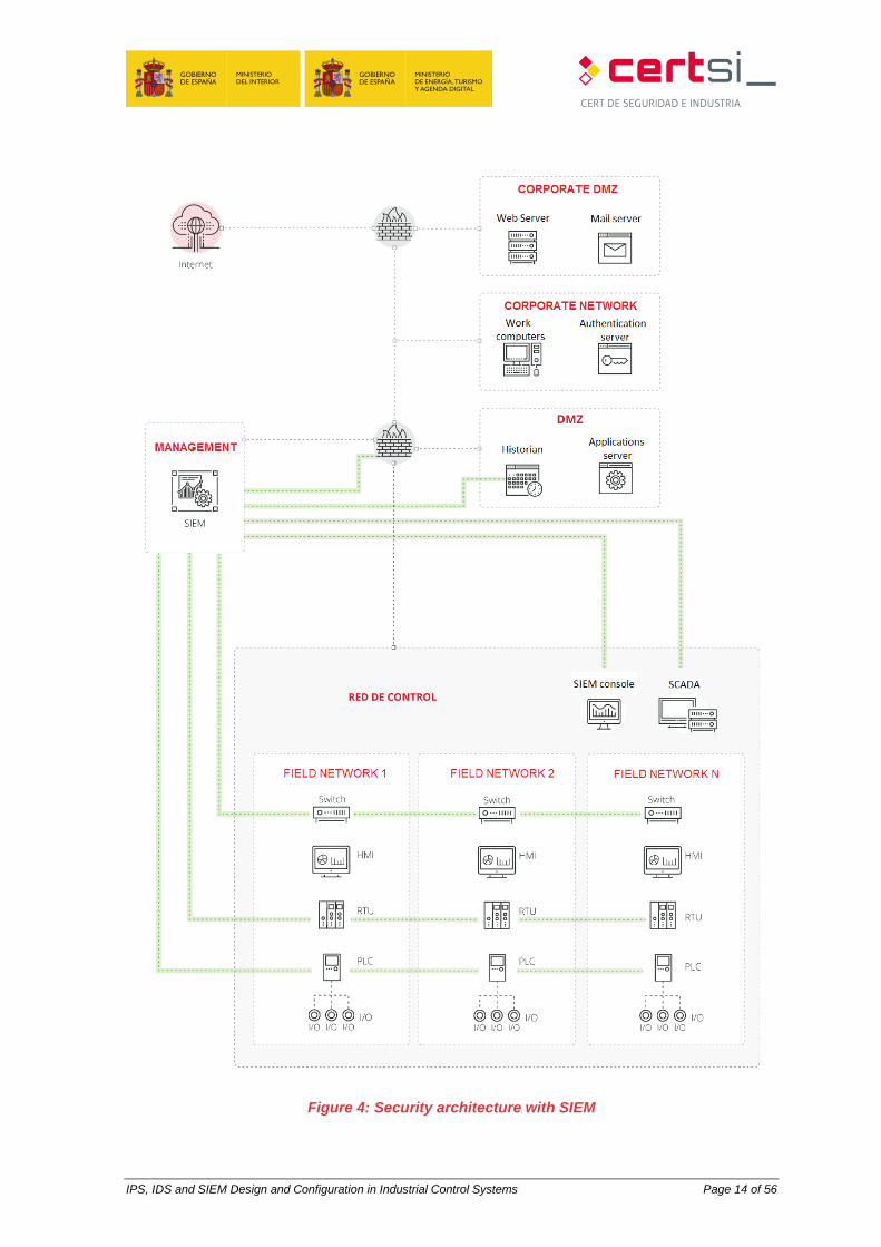
Figure 4 represents the installation of an SIEM within the control systems. One must take
into account that the SIEM is dedicated to collecting and managing the log events, so the
sources of data emerge from all the devices. In this case, one must take care with the
communications as all the devices must be able to send to event logs to the SIEM and this
may lead to an overload of traffic on the network. The best way to resolve this overload is
to avail of an exclusive network for the sending of these messages.
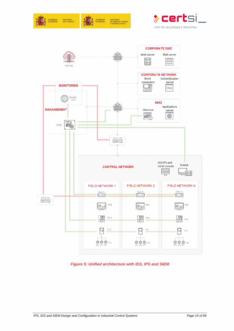
The final representation (Figure 5) shows the putting together of the three technologies
within the architecture of a network control system. The IPS would remain for higher levels,
controlling traffic exchanged between the control part and the business part. The IDS would
manage traffic between the control network and the field, informing of possible anomalies
in the traffic; and the SIEM would collect information from the largest possible number of
devices, including processing devices and network elements as well as information from
alerts from both the IDS and the IPS.
The red lines shown in the diagrams indicated the points where both IDS and IPS sensors
connect to gather the traffic, constituting network connection. The monitoring network is
used as a nexus between the IDS/IPS sensors and the central management nucleus and,
for this reason, access to said network is not required for any architecture from any other
part of the architecture.
The lines marked in green that end en the SIEM show where the information is obtained
and not real network connections. The information will be sent through the existing
connections, with the corresponding rules activated in firewalls (and in some cases in the
IDS/IPS).
IPS, IDS and SIEM Design and Configuration in Industrial Control Systems Page 12 of 56
Figure 2: Security architecture with IDS
IPS, IDS and SIEM Design and Configuration in Industrial Control Systems Page 13 of 56
Figure 3: Security architecture with IPS
IPS, IDS and SIEM Design and Configuration in Industrial Control Systems Page 14 of 56
Figure 4: Security architecture with SIEM
IPS, IDS and SIEM Design and Configuration in Industrial Control Systems Page 15 of 56
Figure 5: Unified architecture with IDS, IPS and SIEM
IPS, IDS and SIEM Design and Configuration in Industrial Control Systems Page 16 of 56
5 INSTALLATION MANUAL
5.1 Introduction
In the following sections, precise step-by-step instructions are provided on how to roll out a
real environment that allows us to detect security events (Snort) and how to subsequently
manage and view them (Snorby).
5.2 Design of laboratory architecture
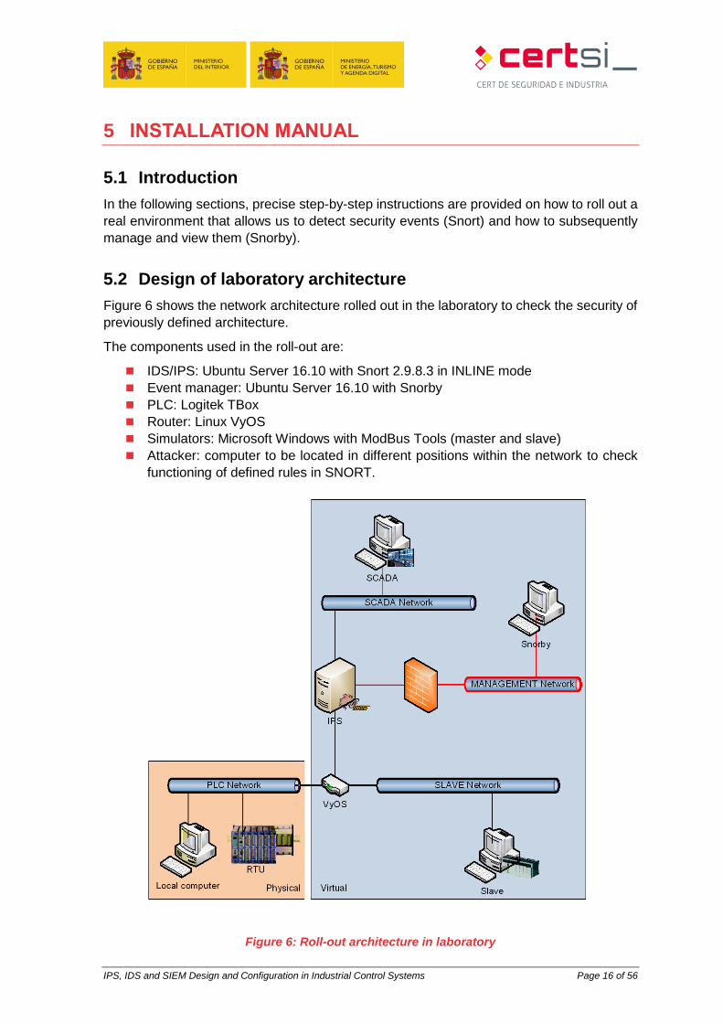
Figure 6 shows the network architecture rolled out in the laboratory to check the security of
previously defined architecture.
The components used in the roll-out are:
IDS/IPS: Ubuntu Server 16.10 with Snort 2.9.8.3 in INLINE mode
Event manager: Ubuntu Server 16.10 with Snorby
PLC: Logitek TBox
Router: Linux VyOS
Simulators: Microsoft Windows with ModBus Tools (master and slave)
Attacker: computer to be located in different positions within the network to check
functioning of defined rules in SNORT.
Figure 6: Roll-out architecture in laboratory
IPS, IDS and SIEM Design and Configuration in Industrial Control Systems Page 17 of 56
5.3 Network design
To carry out the most realistic simulation possible, we decided on a division across three
levels. On level 1, in accordance with SCADA pyramid, two separate network fields are
found, one called the PLC network, which groups together real computers; and another
called the SLAVE network, which groups together virtual simulation computers. Level 2
corresponds to the SCADA network, where the equipment responsible for the collection of
all data from the field is located. At level 3 is the management network, where the computer
responsible for the management of the events produced by the IPS is positioned.
The router is responsible for communications between the different network ranges.
The IPS must be configured in such a way that the traffic between the SCADA network is
not functioning and the PLC and SLAVE networks can continue as normal.
For all the machines in the network, it must be determined if IPv6 is to be used. In that case
that it is not necessary it will be convenient to disable this protocol.
Bridge Creation
The machine that houses the IPS, in this case Snort, requires the configuration of a bridge.
The IPS must be transparent for the network, in such a way that it is not detected and does
not interfere with the communications. For this, the network interfaces it uses do not need
an IP.
To configure the transfer of information between two interfaces that perform the analysis, a
bridge that joins them must be defined for when the IPS is not operating. For that it will be
necessary to change the network configuration.
The first thing to do is to install the packet that allows bridges to be performed.
apt install bridge-utils
Subsequently, the bridge interface must be configured.
/etc/network/interfaces
auto br0
iface br0 inet manual
bridge-ports eth0 eth1
bridge_stp off
bridge_fd 0
When the IPS is operational, this bridge must be disabled, for which it will be necessary to
modify some IPS configuration files so that it does so automatically. Alternatively, you can
do so manually using the following commands:
ifconfig br0 down
“Execution of IPS”
ifconfig br0 up -arp
5.4 Installation of Snort
IPS, IDS and SIEM Design and Configuration in Industrial Control Systems Page 18 of 56
For the installation of SNORT in the laboratory, an Ubuntu Server 16.04 computer must be
used. The installation of IPS on Linux follows the same installation procedure as any other
Linux packet.
apt install snort
The IPS installation folder is /etc/snort, and there both the configuration files and those
related to the operation rules will remain.
As it is intended put the IPS in INLINE mode, it is necessary to also install the Data
AcQuisition library (DAQ) accessory.
We must remember that an IDS/IPS in a control system put in INLINE mode blocking traffic
must only be activated after a thorough study of the information in transit in order to be
completely sure that no control order will be blocked at any time. The activation of INLINE
mode must be used after analysing the traffic used in IDS mode or INLINE TEST mode.
The DAQ must be downloaded directly from the Snort page.
wget https://www.snort.org/downloads/snort/daq-X.X.X.tar.gz
tar zxf daq-X.X.X.tar.gz
cd daq-X.X.X
./configure
make && make install
ldconfig
Bear in mind the DAQ version to install must be indicated.
Dependencies
For the execution of Snort and DAQ a series of libraries are necessary. These must be
installed in advance of the installation of the other two components, as otherwise they will
fail.
apt install libdnet libdnet-dev libpcap-dev make automake gc flex bison libdumbnet-
dev
Some libraries have changed name and it is necessary to create a symbolic link to one of
these so that everything works correctly.
ln –s /usr/include/dumbnet.h /usr/include/dnet.h
ldconfig
Configuration
The general Snort configuration is found in the snort.conf. file. In addition to the changes
made to this file, it is necessary to perform modifications of other configuration files.
5.4.2.1 Snort.conf
Within the Snort configuration file it is necessary to modify some parameters so that the
system can function as an INLINE IPS. Search for the values and change them in the correct
place in snort.conf.
IPS, IDS and SIEM Design and Configuration in Industrial Control Systems Page 19 of 56
ipvar HOME_NET 192.168.1.0/24 #Modify to range of specific network
ipvar EXTERNAL_NET !HOME_NET
config daq: afpacket
config daq_mode: inline
In the same file, you must configure the rules files to be used. A preconfigured selection of
files and rules that we can personalise comes by default.
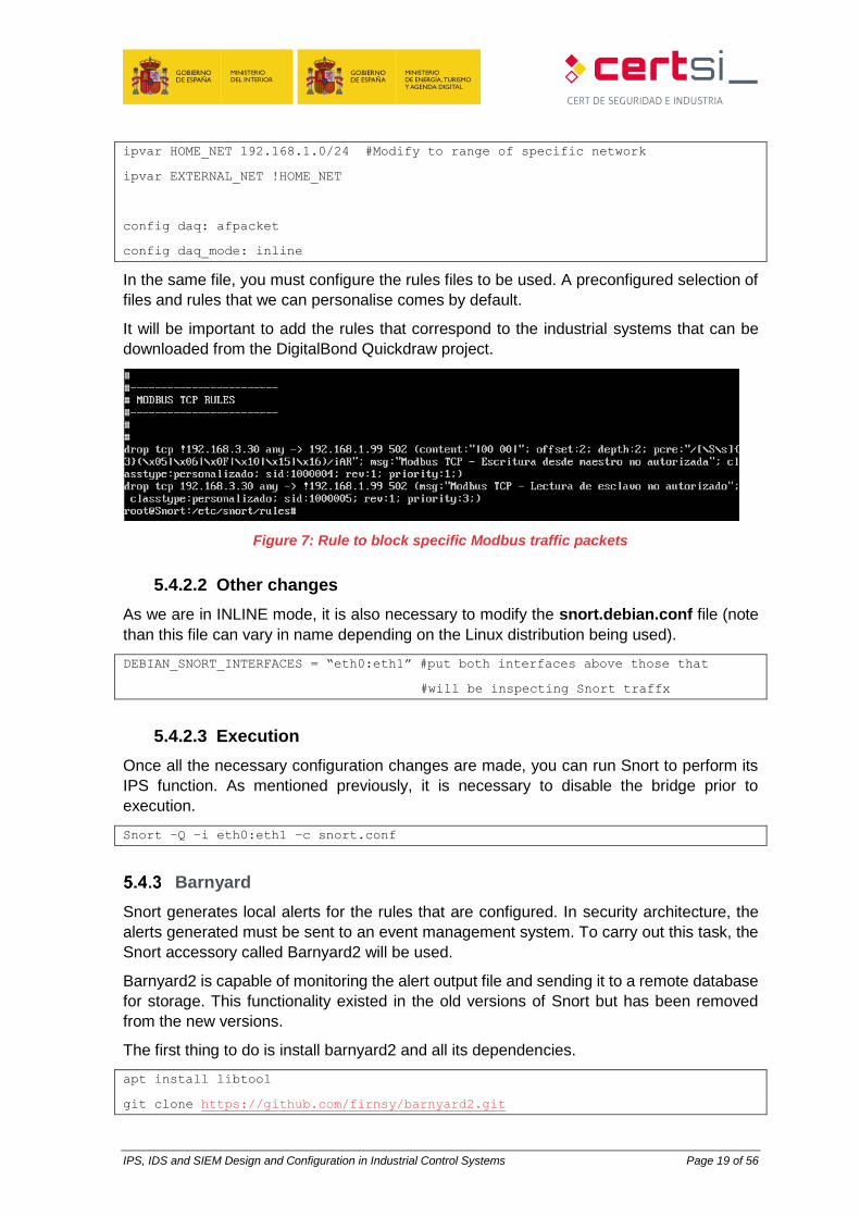
It will be important to add the rules that correspond to the industrial systems that can be
downloaded from the DigitalBond Quickdraw project.
Figure 7: Rule to block specific Modbus traffic packets
5.4.2.2 Other changes
As we are in INLINE mode, it is also necessary to modify the snort.debian.conf file (note
than this file can vary in name depending on the Linux distribution being used).
DEBIAN_SNORT_INTERFACES = “eth0:eth1” #put both interfaces above those that
#will be inspecting Snort traffx
5.4.2.3 Execution
Once all the necessary configuration changes are made, you can run Snort to perform its
IPS function. As mentioned previously, it is necessary to disable the bridge prior to
execution.
Snort –Q –i eth0:eth1 –c snort.conf
Barnyard
Snort generates local alerts for the rules that are configured. In security architecture, the
alerts generated must be sent to an event management system. To carry out this task, the
Snort accessory called Barnyard2 will be used.
Barnyard2 is capable of monitoring the alert output file and sending it to a remote database
for storage. This functionality existed in the old versions of Snort but has been removed
from the new versions.
The first thing to do is install barnyard2 and all its dependencies.
apt install libtool
git clone https://github.com/firnsy/barnyard2.git
IPS, IDS and SIEM Design and Configuration in Industrial Control Systems Page 20 of 56
Once downloaded, continue with the installation and configuration
./autogen.sh
./configure
make && make install
Subsequently you must instruct Barnyard where to send the alerts. This configuration is
contained in the barnyard.conf. file.
output database alert,mysql user=usuario password=contraseña dbname=nombre_bbdd
host=host_remoto
Where:
User defined in the mysql destination database
Password: user password
Name_bbdd: Name of the defined destination database
Remote_host: IP or name of remote host to which to send alerts
It is now necessary to instruct Snort to perform an output in a format that Barnyard can
understand. For that it will be necessary to modify the output of the snort.conf. file.
output unified2: filename fichero limit 128
Where:
File: snort alert output file
To carry a log of alerts that have already been sent to the database between different
barnyard2 executions it is necessary to create a persistence file which we will leave in the
same folder as the logs to be sent.
touch /var/log/snort/bardyar2.waldo
Once all of the configuration has been carried out, you can run barnyard2 (note that the
database to which the logs are sent should exist)
barnyard2 –c /etc/snort/barnyard2.conf –d /var/log/snort –f snort.conf –w
/var/log/snort/barnyard2.waldo
Figure 8: Sending Snort alerts to Snorby through Barnyard2
5.5 Collection and analysis of alerts and events
In all security systems, the collection and analysis of alerts generated is something very
valuable. The alerts generated by Snort are complex to manage as they are collected in a
text file, which is why, to facilitate their handling, use has been made of the event
management system, in this case Snorby.
IPS, IDS and SIEM Design and Configuration in Industrial Control Systems Page 21 of 56
Dependencies
Snorby requires various accessory packets in order to be able to function. The principal
packets are the database for keeping all the information including mysql and the apache to
be able to roll it out as it consists of a web application.
The dependencies necessary to install:
apt install apache2 apach2-dev mysql-server libmysqlclient-dev ruby-full
postgreesql-server-dev-9.5 libcurl4-apoenssl-dev
Snorby installation and configuration
The installation of Snorby begins with the creation of a data base to store all the information
on the alerts received.
mysql -u root -p
> create database snorby;
> create user ‘user@’%’ identified by ‘password’
> grant all privileges on snorby.* to user@’%’ with grant option;
> flush privileges;
> quit
Where:
User: username for use by Snorby in the database
Password: Password selected for defined user.
We then download Snorby and copy it to the apache roll-out folder.
git clone https://github.com/Snorby/snorby.git
cp –r snorby /var/www/html
Due to the changes of versions, it is necessary to modify the Gemfile file
gem ‘rake’, ‘0.9.2’ gem ‘rake’, ‘> 0.9.2’
after gem ‘json’,’X.X’ add gem ‘thin’
in the group section (:development) to comment gem ‘thin’
And the Gemfile.lock file
rake (0.9.2) rake (0.9.2.2)
It will then be necessary to install ruby gems and create the configuration files.
gem install rails bundler passenger wkhtmltopdf do_postgres –v ‘0.10.16’
bundle install
cp config/snorby_config.yml.example config/snorby_config.yml
cp config/database.yml.example config/database.yml
The configuration of access to the database is found in the database.yml file, where it will
be necessary to specify the database and the user created in advance.
To ensure that the integration of Snorby and ruby with Apache is correct, it is necessary to
install a module:
IPS, IDS and SIEM Design and Configuration in Industrial Control Systems Page 22 of 56
passenger-install-apache2-module
At the end of the installation, a series of lines are displayed that must be added to the
snorby.conf. file. This file does not exist and must be created in advance:
touch /etc/apache2/sites-available/snorby.conf
The lines will be similar to the following:
LoadModule passenger_module /var/lib/gems/2.3.0/gems/passenger-
5.0.30/buildout/apache2/mod_passenger.so
PassengerRoot /var/lib/gems/2.3.0/gems/passenger-5.0.30
PassengerDefaultRuby /usr/bin/ruby2.3
In addition to the previous lines, the following lines must be added to the snorby.confs file:
Servername 192.168.1.200
DocumentRoot /var/www/html/snorby/public
<Directory /var/www/html/>
AllowOverride all
Order allow,deny
Allow from all
Options –MultiViews
</Directory>
So that Snorby can adequately read the configuration it is necessary to create a symbolic
link and remove the default configuration.
ln -s /etc/apache2/sites-available/snorby.conf /etc/apache2/sites-
enabled/snorby.conf
rm /etc/apache2/sites-enabled/000-default.conf
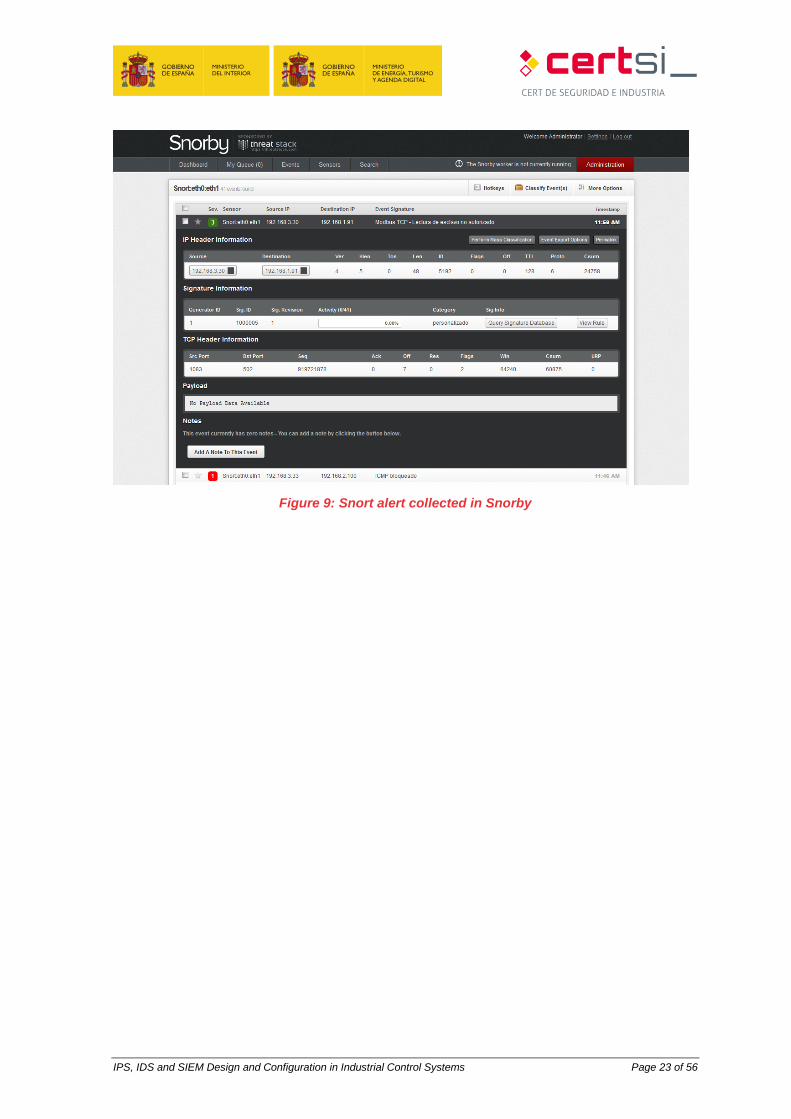
You can now run Snorby to display the Snort alerts.
RAILS_ENV=production bundle exec rake snorby:setup
Access is made through the browser. The first access is made using the following
credentials:
Username: [email protected]
Password: snorby
Once inside it is important to change this username and password and create as many new
ones as are required.
IPS, IDS and SIEM Design and Configuration in Industrial Control Systems Page 23 of 56
Figure 9: Snort alert collected in Snorby
IPS, IDS and SIEM Design and Configuration in Industrial Control Systems Page 24 of 56
6 CONCLUSIONS
The intrusion detection and prevention systems and the event and incident response and
management systems provide a degree of security to control systems provided that they
are correctly configured and supervised.
The configuration of a prevention system might imply many problems for a control system
in production, which is why all the implications must be assessed correctly, and all possible
prior tests must be run, including those of maintaining the system only in detection mode
until absolutely certain that critical traffic will not be blocked from the system and continue
refining the system progressively so that it only detects or reports on important events.
The SIEMs provide information of the status of the system to security operators but it is only
useful if the information collected is correctly analysed. Centralising all events in a single
terminal has the advantage that all actions occurred will be controlled in the minimum period
of time and will not be lost due to having to revise multiple applications.
The inclusion of these tools in the control system architecture can be complex depending
on the system you want to control, but the benefits will compensate all the effort invested in
the roll-out, gaining control of the network and allowing us to ensure correct functioning of
the system without intrusions.
IPS, IDS and SIEM Design and Configuration in Industrial Control Systems Page 25 of 56
ANNEX 1. FUNDAMENTALS OF MONITORING
TECHNOLOGY
ANNEX 1.1. DEFINITIONS
Logical security staff of business systems will be familiar with systems covered in this study,
but not all staff involved in industrial control systems are familiar with them. That's why it's
necessary to clarify a definition of each of the systems to be covered.
ANNEX 1.1.1. IDS
The Intrusion Detection System consists of a set of methods and techniques to reveal
suspicious activity with a resource or IT resources. That is, events that suggest an anomaly
in behaviour or incorrect or inappropriate use of a system.
ANNEX 1.1.2. IPS
IPSs are hardware or software devices that are responsible for reviewing traffic in a network
in order to detect and respond to possible attacks or intrusions. The response consists of
removing or modifying packets from the attack in such a way to frustrate their objective.
This behaviour classifies them as proactive devices due to their automatic reaction to
anomalous situations.
ANNEX 1.1.3. SIEM
SIEM solutions are a hybrid solution of categories of products like SIM (Security Information
Management) and SEM (Security Event Manager). SIEM technology provides a real-time
analysis of security alerts generated by the network hardware and software. The SIEM
solutions can come from software applications or administration services, and are also used
to register security data and generate reports for compliance purposes.
ANNEX 1.2. IDS
An Intrusion Detection System can be described as a detection and monitoring process of
events that occur in a network. This system listens and analyses all the information that
circulates in a network, helps us understand attacks, estimates the damage caused and
tries to prevent other attacks.
To detect intrusions in a system, IDSs use three types of information: a log of events, the
current configuration of the system and active system processes or rules.
IPS, IDS and SIEM Design and Configuration in Industrial Control Systems Page 26 of 56
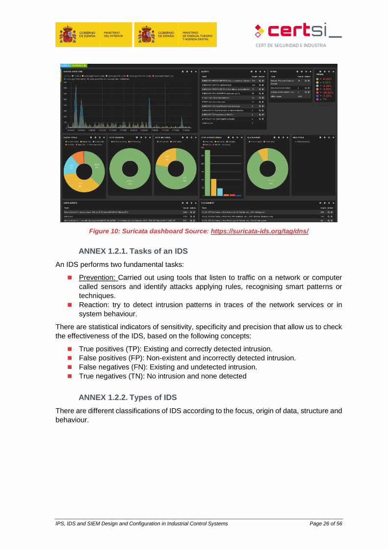
Figure 10: Suricata dashboard Source: https://suricata-ids.org/tag/dns/
ANNEX 1.2.1. Tasks of an IDS
An IDS performs two fundamental tasks:
Prevention: Carried out using tools that listen to traffic on a network or computer
called sensors and identify attacks applying rules, recognising smart patterns or
techniques.
Reaction: try to detect intrusion patterns in traces of the network services or in
system behaviour.
There are statistical indicators of sensitivity, specificity and precision that allow us to check
the effectiveness of the IDS, based on the following concepts:
True positives (TP): Existing and correctly detected intrusion.
False positives (FP): Non-existent and incorrectly detected intrusion.
False negatives (FN): Existing and undetected intrusion.
True negatives (TN): No intrusion and none detected
ANNEX 1.2.2. Types of IDS
There are different classifications of IDS according to the focus, origin of data, structure and
behaviour.
IPS, IDS and SIEM Design and Configuration in Industrial Control Systems Page 27 of 56
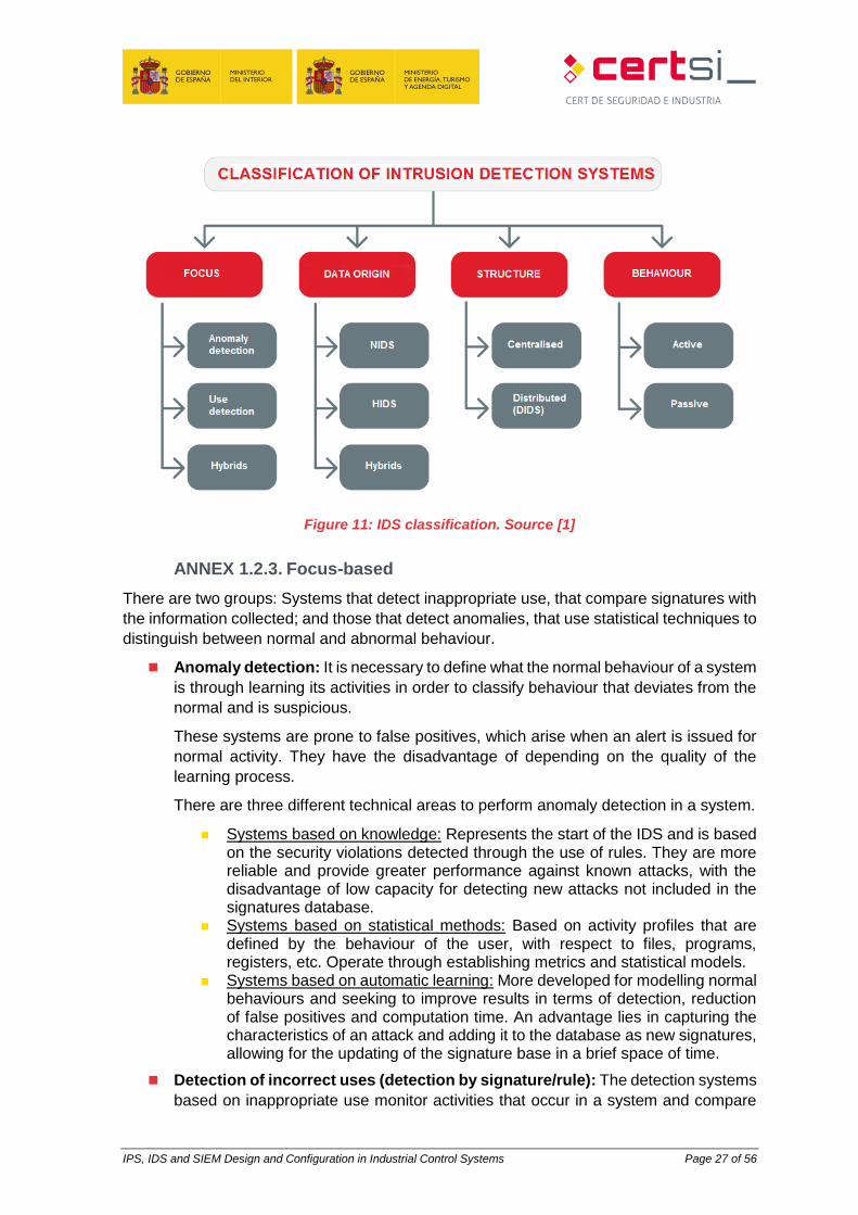
Figure 11: IDS classification. Source [1]
ANNEX 1.2.3. Focus-based
There are two groups: Systems that detect inappropriate use, that compare signatures with
the information collected; and those that detect anomalies, that use statistical techniques to
distinguish between normal and abnormal behaviour.
Anomaly detection: It is necessary to define what the normal behaviour of a system
is through learning its activities in order to classify behaviour that deviates from the
normal and is suspicious.
These systems are prone to false positives, which arise when an alert is issued for
normal activity. They have the disadvantage of depending on the quality of the
learning process.
There are three different technical areas to perform anomaly detection in a system.
Systems based on knowledge: Represents the start of the IDS and is based on the security violations detected through the use of rules. They are more reliable and provide greater performance against known attacks, with the disadvantage of low capacity for detecting new attacks not included in the signatures database.
Systems based on statistical methods: Based on activity profiles that are defined by the behaviour of the user, with respect to files, programs, registers, etc. Operate through establishing metrics and statistical models.
Systems based on automatic learning: More developed for modelling normal behaviours and seeking to improve results in terms of detection, reduction of false positives and computation time. An advantage lies in capturing the characteristics of an attack and adding it to the database as new signatures, allowing for the updating of the signature base in a brief space of time.
Detection of incorrect uses (detection by signature/rule): The detection systems
based on inappropriate use monitor activities that occur in a system and compare
IPS, IDS and SIEM Design and Configuration in Industrial Control Systems Page 28 of 56
them to a database of attack signatures. When an activity that coincides with these
signatures is found, an alarm is generated.
They are easily adaptable as it is enough to update the database by writing a new
rule or obtaining it from a third party.
Expert Systems: Codified knowledge through rules of engagement (condition-action): if all conditions are fulfilled then the action or rule applies. They have the disadvantage of non-sequential rules, which makes it difficult to isolate intrusions in time.
Signature detection: Makes comparisons between events that occur in the system and in signatures stored in the database in search of similarities.
Analysis of transaction status: Attacks are represented as a sequence of transitions (finite machine statuses). When a status considered an intrusion is reached, an alert is issued.
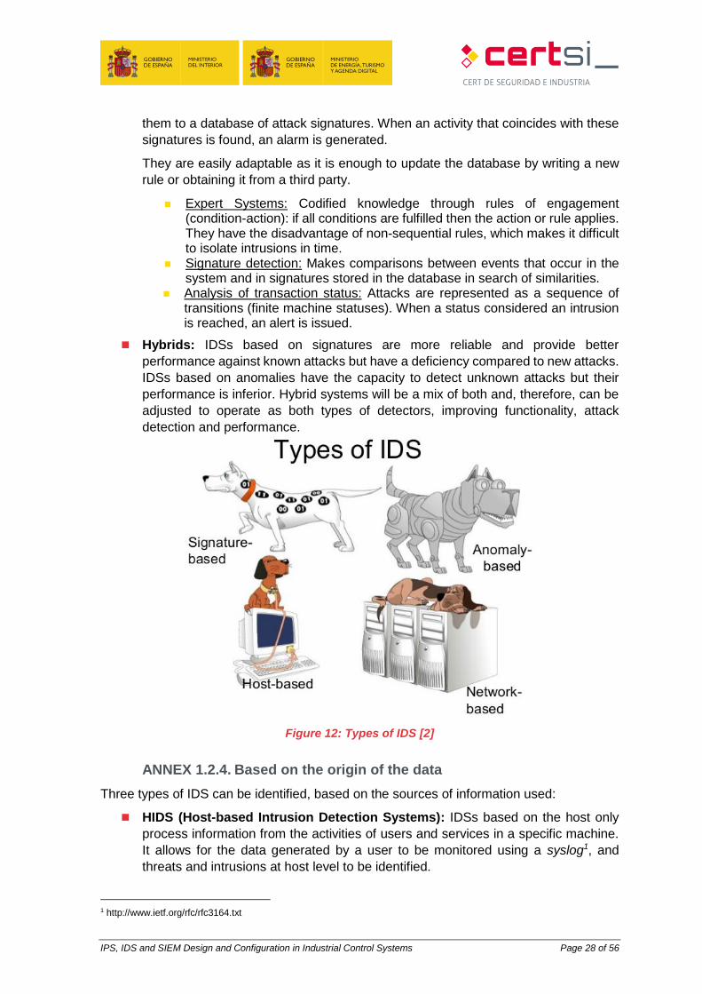
Hybrids: IDSs based on signatures are more reliable and provide better
performance against known attacks but have a deficiency compared to new attacks.
IDSs based on anomalies have the capacity to detect unknown attacks but their
performance is inferior. Hybrid systems will be a mix of both and, therefore, can be
adjusted to operate as both types of detectors, improving functionality, attack
detection and performance.
Figure 12: Types of IDS [2]
ANNEX 1.2.4. Based on the origin of the data
Three types of IDS can be identified, based on the sources of information used:
HIDS (Host-based Intrusion Detection Systems): IDSs based on the host only
process information from the activities of users and services in a specific machine.
It allows for the data generated by a user to be monitored using a syslog1, and
threats and intrusions at host level to be identified.
1 http://www.ietf.org/rfc/rfc3164.txt
IPS, IDS and SIEM Design and Configuration in Industrial Control Systems Page 29 of 56
An advantage comes from the trust requirement in the system that can be infected
prior to installation and makes it vulnerable to direct attacks.
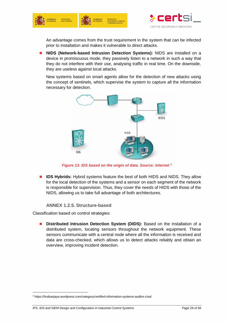
NIDS (Network-based Intrusion Detection Systems): NIDS are installed on a
device in promiscuous mode, they passively listen to a network in such a way that
they do not interfere with their use, analysing traffic in real time. On the downside,
they are useless against local attacks.
New systems based on smart agents allow for the detection of new attacks using
the concept of sentinels, which supervise the system to capture all the information
necessary for detection.
Figure 13: IDS based on the origin of data. Source: Internet 2
IDS Hybrids: Hybrid systems feature the best of both HIDS and NIDS. They allow
for the local detection of the systems and a sensor on each segment of the network
is responsible for supervision. Thus, they cover the needs of HIDS with those of the
NIDS, allowing us to take full advantage of both architectures.
ANNEX 1.2.5. Structure-based
Classification based on control strategies:
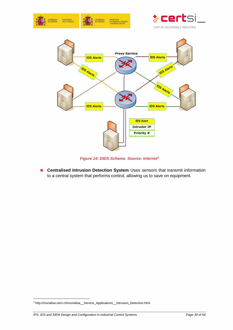
Distributed Intrusion Detection System (DIDS): Based on the installation of a
distributed system, locating sensors throughout the network equipment. These
sensors communicate with a central node where all the information is received and
data are cross-checked, which allows us to detect attacks reliably and obtain an
overview, improving incident detection.
2 https://hndsanjaya.wordpress.com/category/certified-information-systems-auditor-cisa/
IPS, IDS and SIEM Design and Configuration in Industrial Control Systems Page 30 of 56
Figure 14: DIDS Scheme. Source: Internet3
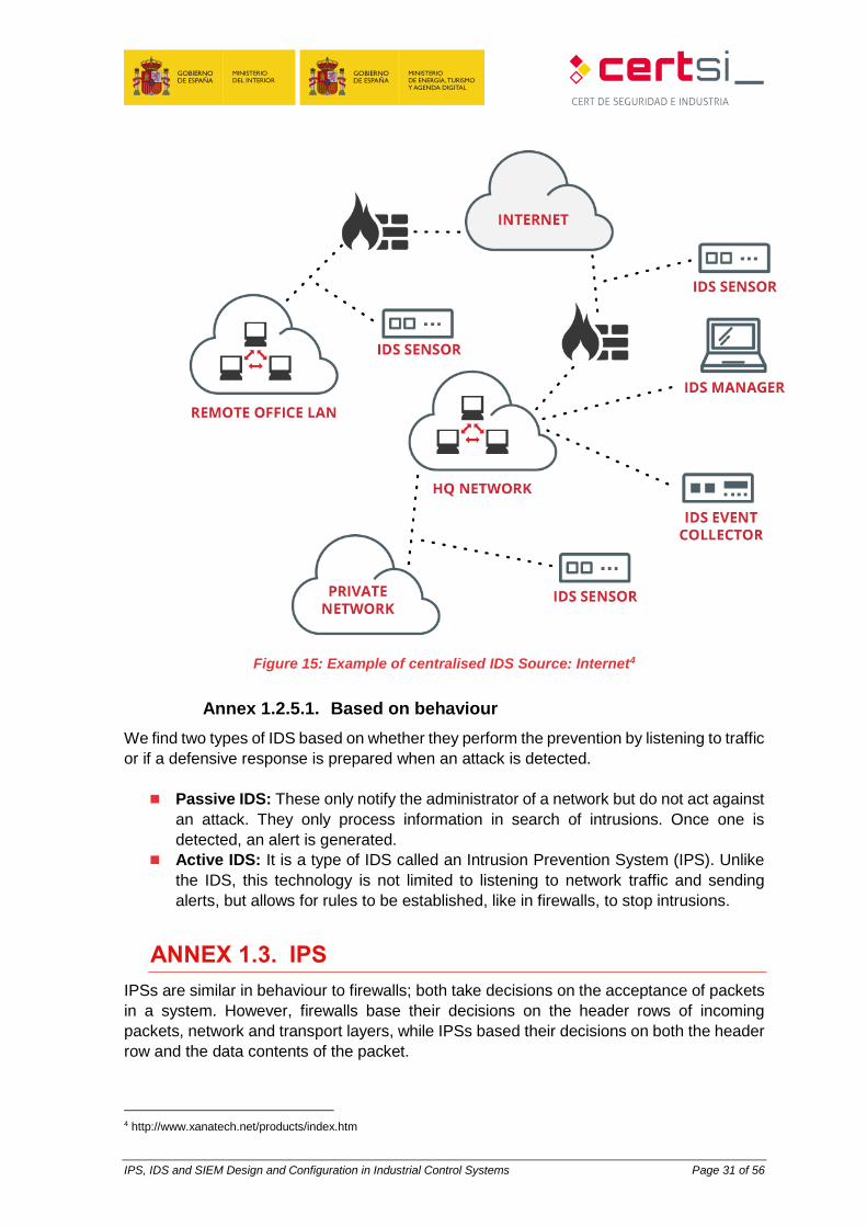
Centralised Intrusion Detection System Uses sensors that transmit information
to a central system that performs control, allowing us to save on equipment.
3 http://monalisa.cern.ch/monalisa__Service_Applications__Intrusion_Detection.html
IPS, IDS and SIEM Design and Configuration in Industrial Control Systems Page 31 of 56
Figure 15: Example of centralised IDS Source: Internet4
Annex 1.2.5.1. Based on behaviour
We find two types of IDS based on whether they perform the prevention by listening to traffic
or if a defensive response is prepared when an attack is detected.
Passive IDS: These only notify the administrator of a network but do not act against
an attack. They only process information in search of intrusions. Once one is
detected, an alert is generated.
Active IDS: It is a type of IDS called an Intrusion Prevention System (IPS). Unlike
the IDS, this technology is not limited to listening to network traffic and sending
alerts, but allows for rules to be established, like in firewalls, to stop intrusions.
ANNEX 1.3. IPS
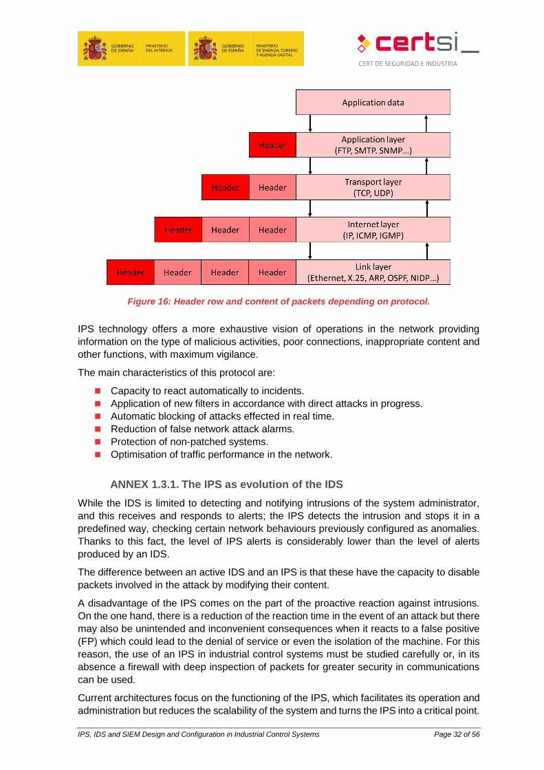
IPSs are similar in behaviour to firewalls; both take decisions on the acceptance of packets
in a system. However, firewalls base their decisions on the header rows of incoming
packets, network and transport layers, while IPSs based their decisions on both the header
row and the data contents of the packet.
4 http://www.xanatech.net/products/index.htm
IPS, IDS and SIEM Design and Configuration in Industrial Control Systems Page 32 of 56
Figure 16: Header row and content of packets depending on protocol.
IPS technology offers a more exhaustive vision of operations in the network providing
information on the type of malicious activities, poor connections, inappropriate content and
other functions, with maximum vigilance.
The main characteristics of this protocol are:
Capacity to react automatically to incidents.
Application of new filters in accordance with direct attacks in progress.
Automatic blocking of attacks effected in real time.
Reduction of false network attack alarms.
Protection of non-patched systems.
Optimisation of traffic performance in the network.
ANNEX 1.3.1. The IPS as evolution of the IDS
While the IDS is limited to detecting and notifying intrusions of the system administrator,
and this receives and responds to alerts; the IPS detects the intrusion and stops it in a
predefined way, checking certain network behaviours previously configured as anomalies.
Thanks to this fact, the level of IPS alerts is considerably lower than the level of alerts
produced by an IDS.
The difference between an active IDS and an IPS is that these have the capacity to disable
packets involved in the attack by modifying their content.
A disadvantage of the IPS comes on the part of the proactive reaction against intrusions.
On the one hand, there is a reduction of the reaction time in the event of an attack but there
may also be unintended and inconvenient consequences when it reacts to a false positive
(FP) which could lead to the denial of service or even the isolation of the machine. For this
reason, the use of an IPS in industrial control systems must be studied carefully or, in its
absence a firewall with deep inspection of packets for greater security in communications
can be used.
Current architectures focus on the functioning of the IPS, which facilitates its operation and
administration but reduces the scalability of the system and turns the IPS into a critical point.
IPS, IDS and SIEM Design and Configuration in Industrial Control Systems Page 33 of 56
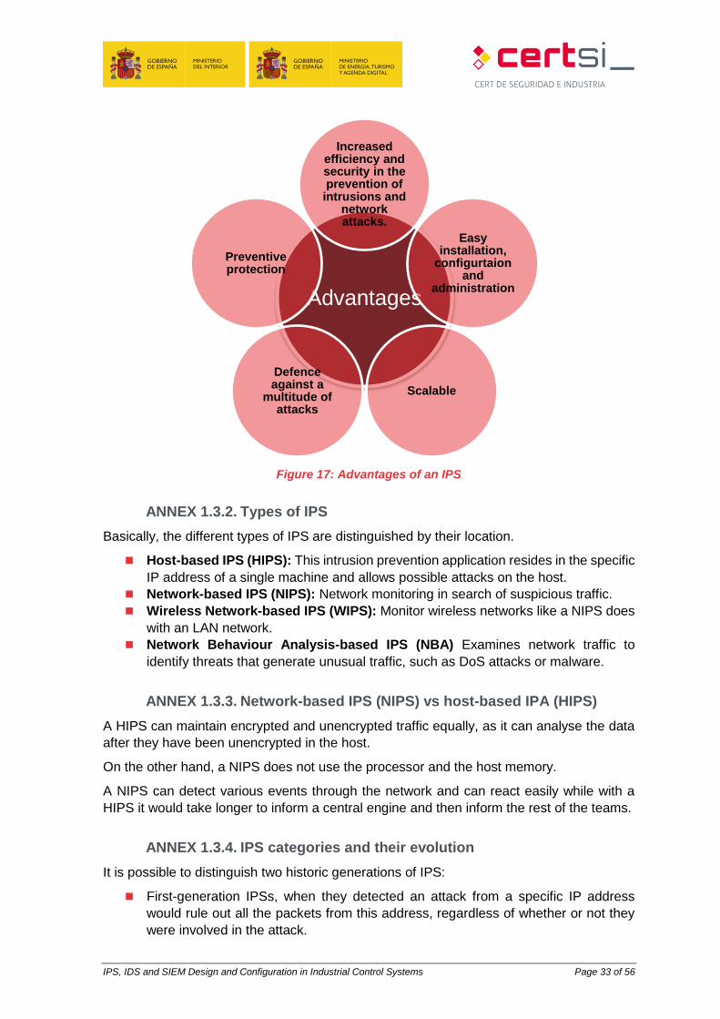
Figure 17: Advantages of an IPS
ANNEX 1.3.2. Types of IPS
Basically, the different types of IPS are distinguished by their location.
Host-based IPS (HIPS): This intrusion prevention application resides in the specific
IP address of a single machine and allows possible attacks on the host.
Network-based IPS (NIPS): Network monitoring in search of suspicious traffic.
Wireless Network-based IPS (WIPS): Monitor wireless networks like a NIPS does
with an LAN network.
Network Behaviour Analysis-based IPS (NBA) Examines network traffic to
identify threats that generate unusual traffic, such as DoS attacks or malware.
ANNEX 1.3.3. Network-based IPS (NIPS) vs host-based IPA (HIPS)
A HIPS can maintain encrypted and unencrypted traffic equally, as it can analyse the data
after they have been unencrypted in the host.
On the other hand, a NIPS does not use the processor and the host memory.
A NIPS can detect various events through the network and can react easily while with a
HIPS it would take longer to inform a central engine and then inform the rest of the teams.
ANNEX 1.3.4. IPS categories and their evolution
It is possible to distinguish two historic generations of IPS:
First-generation IPSs, when they detected an attack from a specific IP address
would rule out all the packets from this address, regardless of whether or not they
were involved in the attack.
Advantages
Increased efficiency and security in the prevention of intrusions and
network attacks.
Easy installation,
configurtaion and
administration
Scalable
Defence against a
multitude of attacks
Preventive protection
IPS, IDS and SIEM Design and Configuration in Industrial Control Systems Page 34 of 56
The evolution of IPSs owes to the ability to rule out only those packets related to the
attack identified, allowing traffic from other packets from the same IP as the attacker,
provided they are not related to the attack.
Five categories of IPSs can be distinguished depending on their functioning, their capacities
and their location in the network architecture [9].
ANNEX 1.3.5. Inline IPS
This represents an evolution of the NIDS based on signatures and that fulfils the function of
a Bridge at layer two level, reviewing all packets that circulate in a network in search of
signatures. In the case of detecting an anomaly automatically, it is stored in a log and can
even allow a packet to pass altering its content in such a way to frustrate the attack, without
the attacker even realising. This process is performed through Scrubbing5, which consists
of error detection via checksum verification or through redundancy with copies of data.
They are commonly known as network IPSs or NIPSs.
Annex 1.3.5.1. Application layer level switches (level 7 of the OSI
model)
Switches usually work on level 2 (link) but switches to level 7 or the relevant application due
to the high demand for bandwidth are increasingly common. The principal task of these
switches is to balance the load of the applications distributed across the different servers,
taking routing and switching decisions from the data content of the application layer. Up to
this point there is no difference with the load balancing.
It functions as an IPS similar to a NIPS based on signatures, serving to block attacks. They
are usually positioned in front of firewall in order to protect the entire network. As they are
similar to a NIPS, they can only stop attacks they know, but allow for DoS and DDoS attacks,
that other IPSs cannot stop and that affect the rest of the network, to be stopped.
They can be configured redundantly, in revolt mode or as load balancer (a characteristic
that differentiates it from other IPSs).
Annex 1.3.5.2. Application Firewalls/IDSs
The firewalls/IDS applications are installed in each host it aims to protect, taking into count
the applications that run within, also known as HIPS. For the correct functioning it shall be
necessary to make a training phase that consists of the process of identification of normal
patterns of functioning in the host.
Through this training a frequent profile of relationships between the applications and the
components of the system is created, like the operating system, other applications, memory
and users.
HIPS behave similarly to IDSs, based on the detection of anomalies to detect intrusions,
but they must identify all the processes exhaustively, as otherwise, they cannot block a valid
application.
5 https://en.wikipedia.org/wiki/Data_scrubbing
IPS, IDS and SIEM Design and Configuration in Industrial Control Systems Page 35 of 56
Due to the fact that they are based on the detection of behavioural anomalies and not on
coinciding signatures, it is possible to prevent more recently developed intrusions for which
no definition of specific signatures exists.
Annex 1.3.5.3. Hybrid Switches
Hybrid switches are a combination between HIPS and application level switches. They are
hardware devices like application level switches but use similar policies to those used by
HIPS.
Hybrid switches are based on the analysis of behavioural patterns. Their strength lies in the
detailed knowledge of traffic which must be accepted.
Annex 1.3.5.4. Misleading applications
This type of technology analyses all the network traffic and each particular device to identify
permitted and correct traffic, similar to how HIPS patterns are used.
In operating mode, when traffic that is not permitted for the network (access to an
unauthorised port) or a specific server (access to an SSH port or a server that is not open)
is detected, it sends a marked response to the attacker, in such a way that the IPS can
detect other traffic from the same source and block it.
ANNEX 1.4. SIEM
The initials SEM, SIM, SIEM have often been used, although the correct meaning of the
term SIEM is a combination of the first two.
SEM: This is the first area of security management. It is concerned with real time
monitoring, correlation of events, notifications and visits to the console that are
commonly recognised as Security Event Management.
SIM: It offers long-term storage, analysis and communication of event data and is
known as Security Information Management.
The term Security Information and Event Management describes multiple capacities
such as gathering, analysis and presentation of information from the network and security
devices. On top of this there are applications for identity and access management,
vulnerability management and compliance policy, the operating system, databases, logs
and external threat data.
The key is to monitor and assist with the control of user and service privileges, directory
services and other changes in the configuration of the system, like providing data for event
audits, review and incident response.
The detection of events of interest can be through any of the functional groups, with SEM
support capable of real time monitoring and SIM, which provides an efficient means of
comparing the large quantity of events collected.
SIEM applications are designed to gather security events from a wide variety that can occur
within an organisation. Once the SIEM has the events, it processes data to standardize
them, analyses the "standardised" data, generates alerts when unusual activity is detected
and issues reports at the request of the administrators. Some SIEM products can also act
to block malicious activities.
IPS, IDS and SIEM Design and Configuration in Industrial Control Systems Page 36 of 56
ANNEX 1.4.1. Real time detection capacity
Security Event Management (SEM) provides tools and functionalities in real time, or almost,
to facilitate the management of events related to security, through the evaluation of the
events and the correlation of information from different sources. As it does not depend on
a single source of information, as IDSs / IPSs do, the function of event management can
help reduce the number of false positives, ensure that the event discovered is
communicated to the other systems. As the database is updated, it becomes more efficient
and can differentiate better between security incidents and the normal patterns of events.
Advanced SEM technologies support the capacity for data visualisation, which can help
rapidly evaluate events and trends. The functions of threat analysis and prioritisation of
events provides extra assistance to security operations staff as they can concentrate their
efforts on investigating the events that have the highest threat classifications.
Annex 1.4.1.1. SEM in Industry
The tools and functionalities provided by the security event manager are often very
competitive in the industrial sector. Due to the use of the proprietary protocols of industrial
elements, it is necessary to carry out exhaustive learning: but thanks to a few changes in
the network and the high reliability it provides high security, to be able to easily detect any
connection or message outside the standard transmission between machines.
ANNEX 1.4.2. Event Archive Management
The functions of SIM are characterised by the analysis of data in real time, through the
collection and standardisation of disparate systems and centralised application information
(for example, system events, audit trail, event registers and transaction registers).
The security analyst can check the archive and recover information through standardised
checks, storing the information from different systems in a single location, in a chronological
and formalised order.
SIM advanced technologies can evaluate these saved events as they are gathered or on
demand, for the purpose of examining anomalous behaviour in future analysis.
Forensic analysis is favoured by event management while centralised events help manage
retention times to meet applicable legislation and standards. The capacity to generate
reports can simplify the internal evaluations and audit cycles of an organization.
SIEM systems provide event detection through real time evaluation of information and real
time forensic analysis of previously stored events.
Annex 1.4.2.1. SIM in Industry
The data collection functions are perfect for auditing processes. Luckily, the data registered
by the sensor are usually homogeneous in networks where the computers are not modified
for long periods of time. Any anomaly is easily detectable in the protocols, values or times,
seeing the changes produced by possible attacks in the network instantly.
ANNEX 1.4.3. Understanding an SIEM
IPS, IDS and SIEM Design and Configuration in Industrial Control Systems Page 37 of 56
SIEMs require a great deal of planning before they are run, identifying and preventing
network violations. Implementation is often seen to be daunting for many companies, and
is often externalised, as it is difficult to adjust and it may take considerable time before the
desired results are obtained.
There are various reasons which could lead a company to implement an SIEM application,
from compliance with a government or industry standard or perhaps to obtain a certain level
of security before signing a contract. Regardless of the reason, where a company decides
to implement an SIEM, it will have to make great efforts before it begins to see results.
ANNEX 1.4.4. Implementation of SIEMs in industrial networks
There are a number of difficulties to the implementation of an SIEM in an OT network:
Long life cycles: The most common problem in industrial systems comes from the
life cycle, often between 20 and 40 years, depending on the type of industry. Adding
security elements to the network or computer can affect, modify or delay the
communications signal of the PLC or other computers due to its low processing
power. This can lead to certain problems in relation to compatibility and functioning
between the computers of this network.
Provisions: The computers found in industrial networks, along with the industrial
devices themselves are usually outdated, not particularly powerful and not updated,
with the bare capacities required for the assigned control tasks. A modern antivirus,
IDS/IPL tools and others necessary for the processing of logs can lead to
incompatibility, reduction of the power of devices or event general malfunction of the
system.
Staff: The employees and technical staff necessary for the management of SIEM
applications must also have sufficient knowledge to understand the protocols and
industrial network equipment to be able to correctly interpret the events generated.
Annex 1.4.4.1. Considerations for the implementation of an SIEM
application
The implementation of an SIEM network requires knowledge of the network topology and
its protocols, and a clear understanding of what it is expected to do. The best way of
implementing an SIEM is through its two most important components separately: the
management of the log and monitoring capacity on the one hand the response to alerts on
the other.
The first task for the organisation will be to establish what it considers a critical asset and,
later, it will go on to the study of its protection.
Some companies have a variety of events to be gathered and processed differently. Before
the SIEM system is capable of providing useful reports, the various events must be
standardised so that the data are coherent.
Before a company can take full advantage of their SIEM, they must configure the system to
cope with the data gathered in each type of device, how and where the data are stored and
how incidents create warnings in addition to managing the time, which can also be a
conditioning factor when it comes to generating the warnings.
IPS, IDS and SIEM Design and Configuration in Industrial Control Systems Page 38 of 56
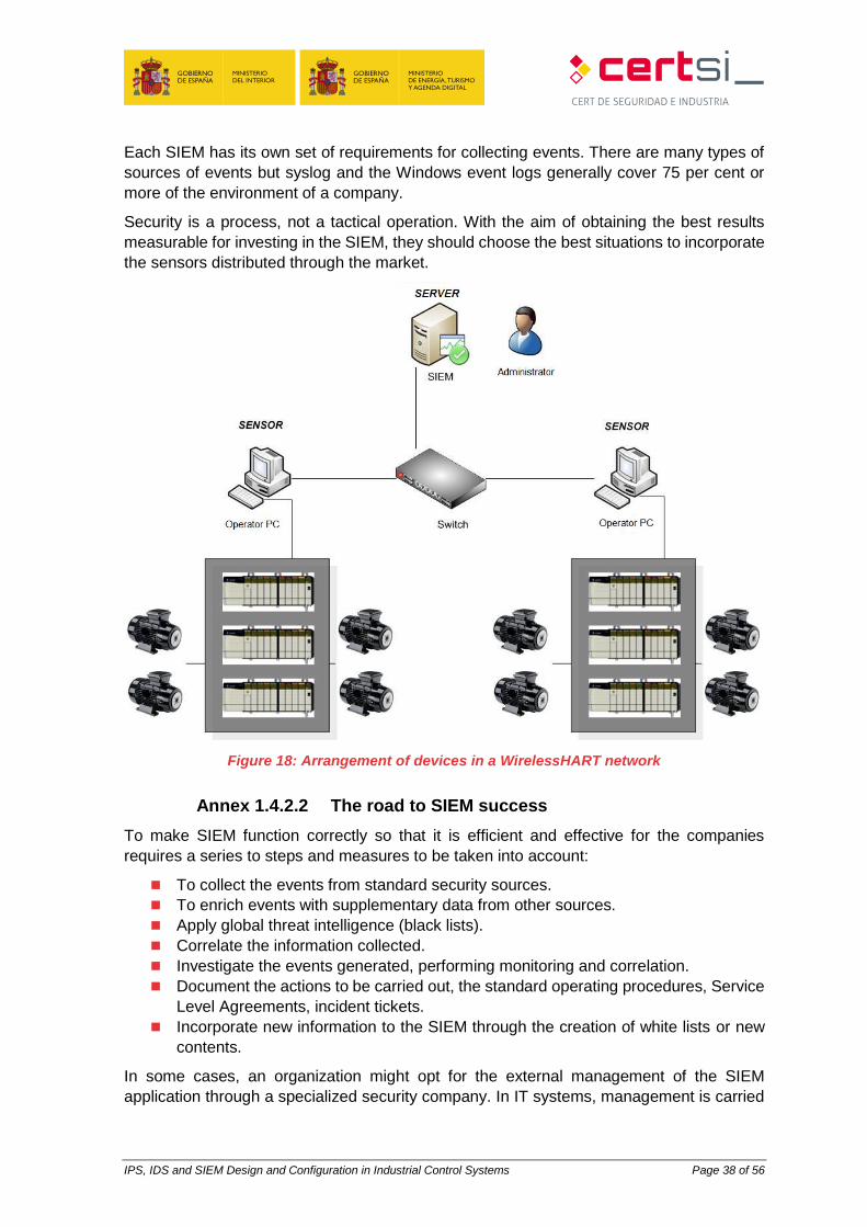
Each SIEM has its own set of requirements for collecting events. There are many types of
sources of events but syslog and the Windows event logs generally cover 75 per cent or
more of the environment of a company.
Security is a process, not a tactical operation. With the aim of obtaining the best results
measurable for investing in the SIEM, they should choose the best situations to incorporate
the sensors distributed through the market.
Figure 18: Arrangement of devices in a WirelessHART network
Annex 1.4.2.2 The road to SIEM success
To make SIEM function correctly so that it is efficient and effective for the companies
requires a series to steps and measures to be taken into account:
To collect the events from standard security sources.
To enrich events with supplementary data from other sources.
Apply global threat intelligence (black lists).
Correlate the information collected.
Investigate the events generated, performing monitoring and correlation.
Document the actions to be carried out, the standard operating procedures, Service
Level Agreements, incident tickets.
Incorporate new information to the SIEM through the creation of white lists or new
contents.
In some cases, an organization might opt for the external management of the SIEM
application through a specialized security company. In IT systems, management is carried
IPS, IDS and SIEM Design and Configuration in Industrial Control Systems Page 39 of 56
out from the company security themselves, but in OT systems it is more common that a
technician or security company move to work together in the industry.
Annex 1.4.4.3. Internal vs External Management
The benefit of a dedicated SIEM is that a company's data never leave the company and it
maintains full control of the hardware and stored events. It has the capacity to configure
correlations (rules), present reports, periods of retention and other adjustments to satisfy
their needs. SIEM applications administered internally can experience problems with
numbers of personnel or that the personnel assigned can be required for other projects or
functions.
Management of an SIEM application requires specialized training and standardised working
procedures which must be created and maintained for each environment. External
administration requires the events to be sent to the administrator and, with this, visibility is
lost.
The disadvantages faced by a client with an externalized SIEM application include: lack of
visibility and inability to move between providers and maintain older events. This lack of
visibility causes problems in the search for new threats.
Given the providers of managed services usually specialise in the SIEM applications of a
single manufacturer, they are much more efficient and, in general, have greater experience
in running operations.
Annex 1.4.4.4. Capacities of an SIEM application
Data aggregation: SEM / LM solutions for log administration from many sources
including networks, security, servers, databases and applications, providing the
capacity to consolidate monitored data to help prevent the loss of crucial events.
Correlation: seeks common attributes and related events in packets or incidents.
This technology performs correlation techniques to integrate different sources in
order to turn data into information.
Alert: automated analysis of correlated events and the production of alerts, sent to
the administrator.
Dashboards: SIEM / LM tool to transform data and convert them into informative
tables and graphics that help recognise patterns or identify anomalous activities.
Compliance: SIEM applications can be used to automate the collection of data and
in the preparation of reports adapted to existing standards.
Retention: SIEM / SIM applications use long-term solutions for data storage, which
constitute a critical process in forensic investigation, as it is unlikely that the
discovery of a violation of the network will happen in the instant in which it occurs.
Redundancy: The correlation motors do not need to be redundant; however, it is
advised that the database is redundant in order not to lose information.
Scalability: Allow the system to be configured hierarchically, in such a way that it
can grow, attending to necessities.
Annex 1.4.4.5. Cloud-based SIEM options
IPS, IDS and SIEM Design and Configuration in Industrial Control Systems Page 40 of 56
One area that is starting to grow is SIEM as a cloud-based service. While suppliers on the
cloud can offer special programmes for SIEMaaS clients (SIEM as a Service) for the first
time, bigger providers also want to offer solutions.
Suppliers must recognise that events are the property of the clients, and the clients must
understand that the events can contain confidential company information.
It is recommended that if the company collects protected data, an agreement must be
signed between the two to ensure that data is managed appropriately.
Unlike traditional versions, cloud-based SIEM software applications are billed based on the
model of use and not per server or per user. However, if the SIEM software sends all events
to the cloud, or on the contrary, is configured incorrectly, the cost of bandwidth of the
supplier of the cloud can be high.
Smaller companies can find greater benefits in the use of a provider of services that offer
security based on software as a service (SaaS) or a managed security service provider
(MSSP) who will provide some of the demands in progress.
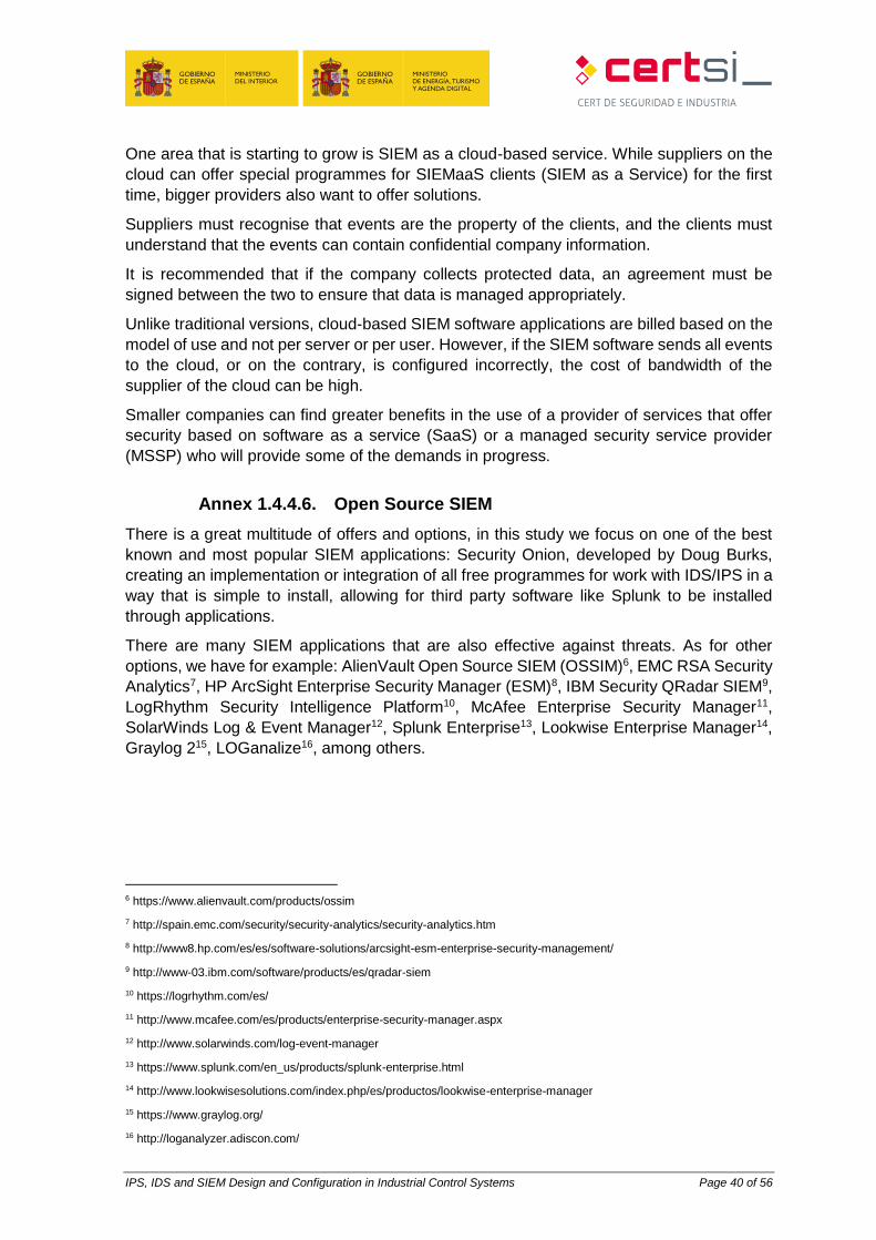
Annex 1.4.4.6. Open Source SIEM
There is a great multitude of offers and options, in this study we focus on one of the best
known and most popular SIEM applications: Security Onion, developed by Doug Burks,
creating an implementation or integration of all free programmes for work with IDS/IPS in a
way that is simple to install, allowing for third party software like Splunk to be installed
through applications.
There are many SIEM applications that are also effective against threats. As for other
options, we have for example: AlienVault Open Source SIEM (OSSIM)6, EMC RSA Security
Analytics7, HP ArcSight Enterprise Security Manager (ESM)8, IBM Security QRadar SIEM9,
LogRhythm Security Intelligence Platform10, McAfee Enterprise Security Manager11,
SolarWinds Log & Event Manager12, Splunk Enterprise13, Lookwise Enterprise Manager14,
Graylog 215, LOGanalize16, among others.
6 https://www.alienvault.com/products/ossim
7 http://spain.emc.com/security/security-analytics/security-analytics.htm
8 http://www8.hp.com/es/es/software-solutions/arcsight-esm-enterprise-security-management/
9 http://www-03.ibm.com/software/products/es/qradar-siem
10 https://logrhythm.com/es/
11 http://www.mcafee.com/es/products/enterprise-security-manager.aspx
12 http://www.solarwinds.com/log-event-manager
13 https://www.splunk.com/en_us/products/splunk-enterprise.html
14 http://www.lookwisesolutions.com/index.php/es/productos/lookwise-enterprise-manager
15 https://www.graylog.org/
16 http://loganalyzer.adiscon.com/

IPS, IDS and SIEM Design and Configuration in Industrial Control Systems Page 41 of 56
ANNEX 2. TECHNOLOGICAL SOLUTIONS
ANNEX 2.1. IDS/IPS Solutions
ANNEX 2.1.1. Snort
Sort is a free software "sniffer" built on libpcap and tcpdump, which allows for the capture
of all traffic that reaches the equipment where it is installed. Snort is designed to be precise
in the logging of activities in the network and continuously searches for possible
coincidences between the flow of data and the attacks that are registered based on different
rules.
Figure 19: Installation of Snort
Snort has a database of attacks that are constantly updated, which, moreover allows for
addition or updating through the Internet. Users can create 'signatures' based on the
characteristics of new network attacks and send them to the Snort sigs mailing list17. This
community has turned Snort into one of the most popular, up to date and robust IDSs.
Another of the most important features of Snort is that the main IDS/IPS manufacturers use
it, and are able to use its signatures on almost any device.
Annex 2.1.1.1. Quickdraw
Quickdraw is a set of rules for Snort, carried out by the company Digital Bond, and serves
to approve the existing IDS through the development of signatures for the control of traffic
of certain protocols, using control systems. Moreover, it also includes rules to detect devices
and vulnerabilities.
Quickdraw signatures (rules in the Snort argot), identify unauthorised requests, requests
and erroneous protocol responses, dangerous commands and other situations that are
probably or possible attacks. At this moment, they have signatures available for four control
system protocols, a set of signatures to identify attacks on control system vulnerabilities
and a group of signatures that identify security events.
17 http://www.snort.org/lists.html

IPS, IDS and SIEM Design and Configuration in Industrial Control Systems Page 42 of 56
ANNEX 2.1.2. Suricata
Suricata is the name of a free software project developed by the Open Information Security
Foundation (OISF) community. It is an engine based on a set of IDS/IPS rules to monitor
traffic in the network and provide alerts to the system administrator when an event is
considered suspicious. It is designed to be compatible with other existing security
components and, moreover, accepts calls from other applications.
Figure 20: Suricata logo18
Annex 2.1.2.1. Description
Suricata can function as a real time IDS, IPS, network security monitor (NSM) or as a pcap
final analyser (files with traffic captures).
The network analysis function is based on rules and signatures, although it can also offer
supports for new scripts through LUA language.
It has standardised inputs and outputs in formats like YAML which allow it to be easily
integrated with other tools like SIEM or databases.
By involving the open source community and the most important set of IDS/IPS rules
resources available, OISF has built the Suricata engine to simplify the process of
maintaining the optimum level of security. Through strategic associations, OISF is taking
advantage of the experience of Emerging Threats19 and other important resources for
industry to provide the most up-to-date and complete rules available.
18 https://suricata-ids.org/
19 www.emergingthreats.net
IPS, IDS and SIEM Design and Configuration in Industrial Control Systems Page 43 of 56
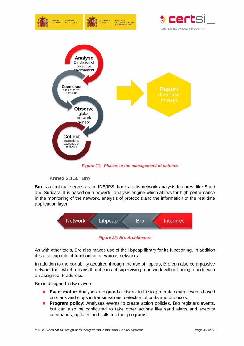
Figure 21: -Phases in the management of patches-
Annex 2.1.3. Bro
Bro is a tool that serves as an IDS/IPS thanks to its network analysis features, like Snort
and Suricata. It is based on a powerful analysis engine which allows for high performance
in the monitoring of the network, analysis of protocols and the information of the real time
application layer.
Figure 22: Bro Architecture
As with other tools, Bro also makes use of the libpcap library for its functioning. In addition
it is also capable of functioning on various networks.
In addition to the portability acquired through the use of libpcap, Bro can also be a passive
network tool, which means that it can act supervising a network without being a node with
an assigned IP address.
Bro is designed in two layers:
Event motor: Analyses and guards network traffic to generate neutral events based
on starts and stops in transmissions, detection of ports and protocols.
Program policy: Analyses events to create action policies. Bro registers events,
but can also be configured to take other actions like send alerts and execute
commands, updates and calls to other programs.
Reportdatabase threats
InterpretBroLibpcapNetwork:
AnalyseEmulation of
objective environment
Counteractrules of threat
detection
Observeglobal
network sensor
Collectinternational exchange of
malware
IPS, IDS and SIEM Design and Configuration in Industrial Control Systems Page 44 of 56
Annex 2.1.4. OSSEC
OSSEC is a host-based IDS (HIDS). It performs log analysis, integrity checks and
supervises the Windows event log, detects rootkits and issues alerts based on time and
active response. Provides intrusion detection for most operating systems including Linux,
OpenBSD, FreeBSD, OS X, Solaris and Windows. OSSEC has a centralised, multiplatform
architecture that allows for various systems to be controlled and managed easily.
OSSEC is based on naming each host as a server or sensor, according to its characteristics.
A sensor will be necessary in each area the network wants to inspect the network in search
of threats and a server, at least to be able to read the data that reaches the sensors.
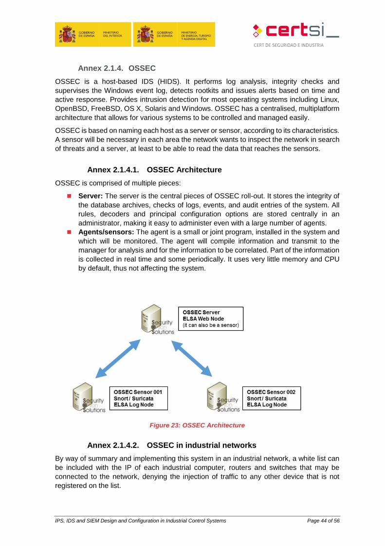
Annex 2.1.4.1. OSSEC Architecture
OSSEC is comprised of multiple pieces:
Server: The server is the central pieces of OSSEC roll-out. It stores the integrity of
the database archives, checks of logs, events, and audit entries of the system. All
rules, decoders and principal configuration options are stored centrally in an
administrator, making it easy to administer even with a large number of agents.
Agents/sensors: The agent is a small or joint program, installed in the system and
which will be monitored. The agent will compile information and transmit to the
manager for analysis and for the information to be correlated. Part of the information
is collected in real time and some periodically. It uses very little memory and CPU
by default, thus not affecting the system.
Figure 23: OSSEC Architecture
Annex 2.1.4.2. OSSEC in industrial networks
By way of summary and implementing this system in an industrial network, a white list can
be included with the IP of each industrial computer, routers and switches that may be
connected to the network, denying the injection of traffic to any other device that is not
registered on the list.
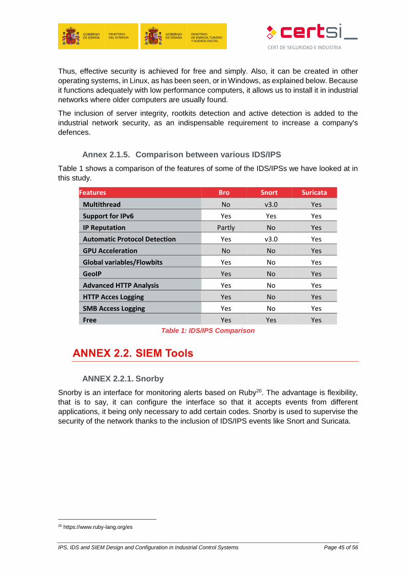
IPS, IDS and SIEM Design and Configuration in Industrial Control Systems Page 45 of 56
Thus, effective security is achieved for free and simply. Also, it can be created in other
operating systems, in Linux, as has been seen, or in Windows, as explained below. Because
it functions adequately with low performance computers, it allows us to install it in industrial
networks where older computers are usually found.
The inclusion of server integrity, rootkits detection and active detection is added to the
industrial network security, as an indispensable requirement to increase a company's
defences.
Annex 2.1.5. Comparison between various IDS/IPS
Table 1 shows a comparison of the features of some of the IDS/IPSs we have looked at in
this study.
Features Bro Snort Suricata
Multithread No v3.0 Yes
Support for IPv6 Yes Yes Yes
IP Reputation Partly No Yes
Automatic Protocol Detection Yes v3.0 Yes
GPU Acceleration No No Yes
Global variables/Flowbits Yes No Yes
GeoIP Yes No Yes
Advanced HTTP Analysis Yes No Yes
HTTP Acces Logging Yes No Yes
SMB Access Logging Yes No Yes
Free Yes Yes Yes
Table 1: IDS/IPS Comparison
ANNEX 2.2. SIEM Tools
ANNEX 2.2.1. Snorby
Snorby is an interface for monitoring alerts based on Ruby20. The advantage is flexibility,
that is to say, it can configure the interface so that it accepts events from different
applications, it being only necessary to add certain codes. Snorby is used to supervise the
security of the network thanks to the inclusion of IDS/IPS events like Snort and Suricata.
20 https://www.ruby-lang.org/es
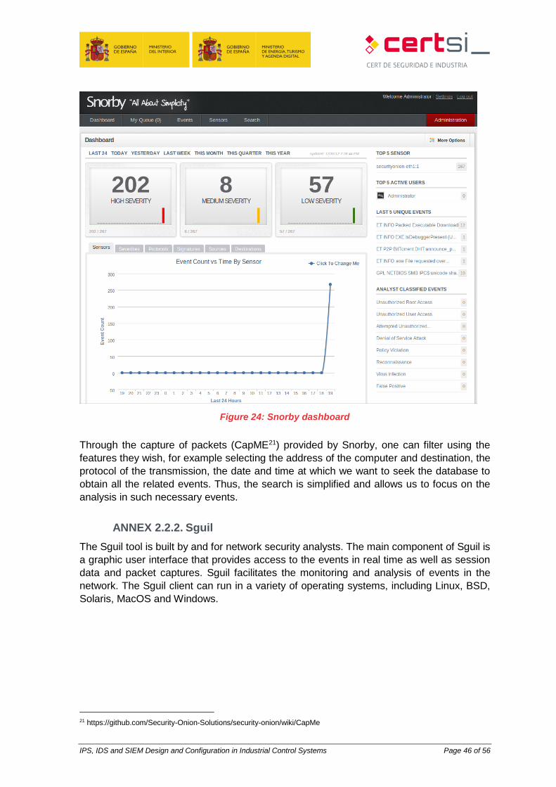
IPS, IDS and SIEM Design and Configuration in Industrial Control Systems Page 46 of 56
Figure 24: Snorby dashboard
Through the capture of packets (CapME21) provided by Snorby, one can filter using the
features they wish, for example selecting the address of the computer and destination, the
protocol of the transmission, the date and time at which we want to seek the database to
obtain all the related events. Thus, the search is simplified and allows us to focus on the
analysis in such necessary events.
ANNEX 2.2.2. Sguil
The Sguil tool is built by and for network security analysts. The main component of Sguil is
a graphic user interface that provides access to the events in real time as well as session
data and packet captures. Sguil facilitates the monitoring and analysis of events in the
network. The Sguil client can run in a variety of operating systems, including Linux, BSD,
Solaris, MacOS and Windows.
21 https://github.com/Security-Onion-Solutions/security-onion/wiki/CapMe
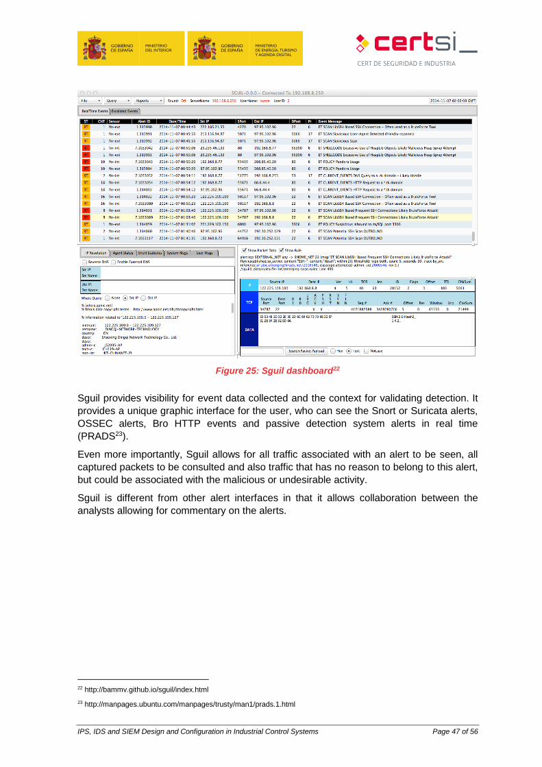
IPS, IDS and SIEM Design and Configuration in Industrial Control Systems Page 47 of 56
Figure 25: Sguil dashboard22
Sguil provides visibility for event data collected and the context for validating detection. It
provides a unique graphic interface for the user, who can see the Snort or Suricata alerts,
OSSEC alerts, Bro HTTP events and passive detection system alerts in real time
(PRADS23).
Even more importantly, Sguil allows for all traffic associated with an alert to be seen, all
captured packets to be consulted and also traffic that has no reason to belong to this alert,
but could be associated with the malicious or undesirable activity.
Sguil is different from other alert interfaces in that it allows collaboration between the
analysts allowing for commentary on the alerts.
22 http://bammv.github.io/sguil/index.html
23 http://manpages.ubuntu.com/manpages/trusty/man1/prads.1.html
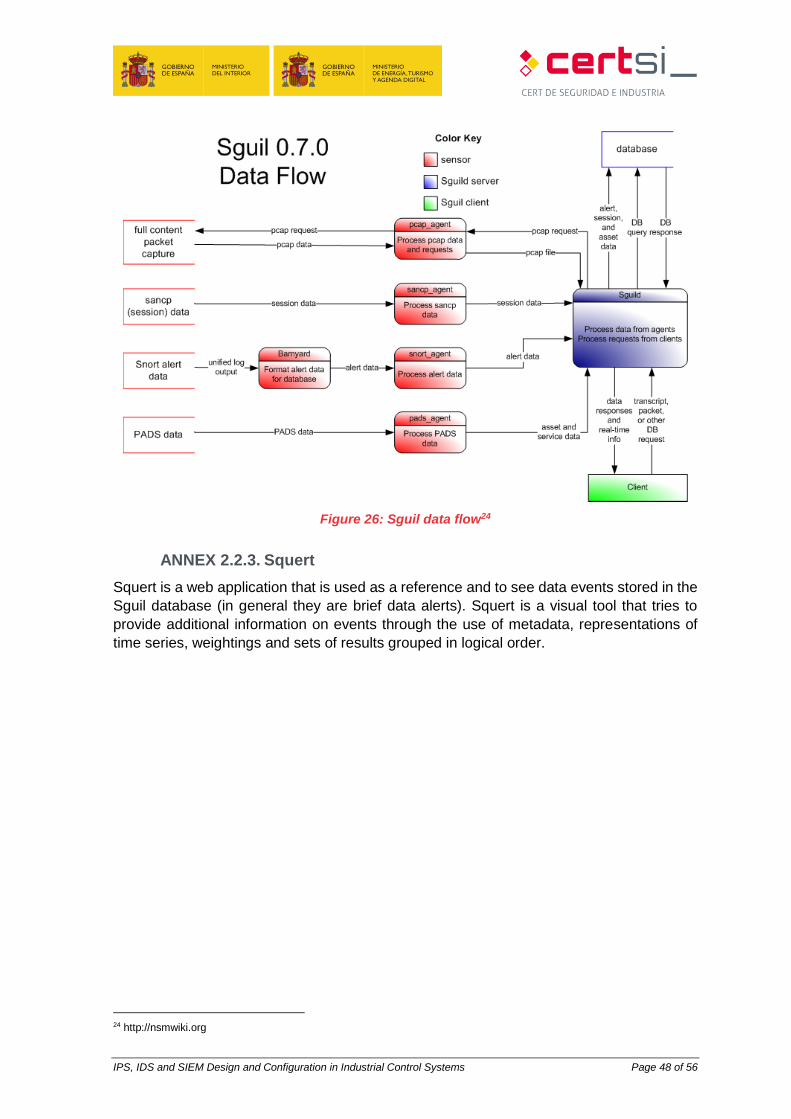
IPS, IDS and SIEM Design and Configuration in Industrial Control Systems Page 48 of 56
Figure 26: Sguil data flow24
ANNEX 2.2.3. Squert
Squert is a web application that is used as a reference and to see data events stored in the
Sguil database (in general they are brief data alerts). Squert is a visual tool that tries to
provide additional information on events through the use of metadata, representations of
time series, weightings and sets of results grouped in logical order.
24 http://nsmwiki.org
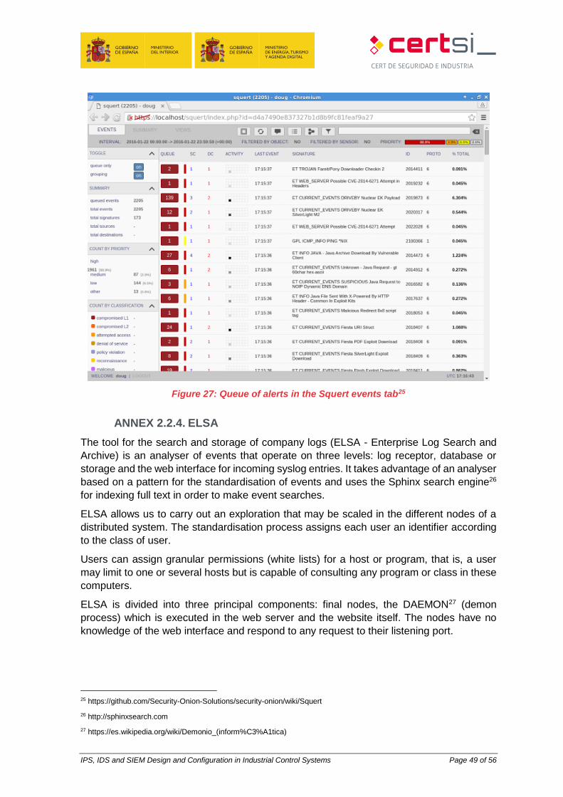
IPS, IDS and SIEM Design and Configuration in Industrial Control Systems Page 49 of 56
Figure 27: Queue of alerts in the Squert events tab25
ANNEX 2.2.4. ELSA
The tool for the search and storage of company logs (ELSA - Enterprise Log Search and
Archive) is an analyser of events that operate on three levels: log receptor, database or
storage and the web interface for incoming syslog entries. It takes advantage of an analyser
based on a pattern for the standardisation of events and uses the Sphinx search engine26
for indexing full text in order to make event searches.
ELSA allows us to carry out an exploration that may be scaled in the different nodes of a
distributed system. The standardisation process assigns each user an identifier according
to the class of user.
Users can assign granular permissions (white lists) for a host or program, that is, a user
may limit to one or several hosts but is capable of consulting any program or class in these
computers.
ELSA is divided into three principal components: final nodes, the DAEMON27 (demon
process) which is executed in the web server and the website itself. The nodes have no
knowledge of the web interface and respond to any request to their listening port.
25 https://github.com/Security-Onion-Solutions/security-onion/wiki/Squert
26 http://sphinxsearch.com
27 https://es.wikipedia.org/wiki/Demonio_(inform%C3%A1tica)
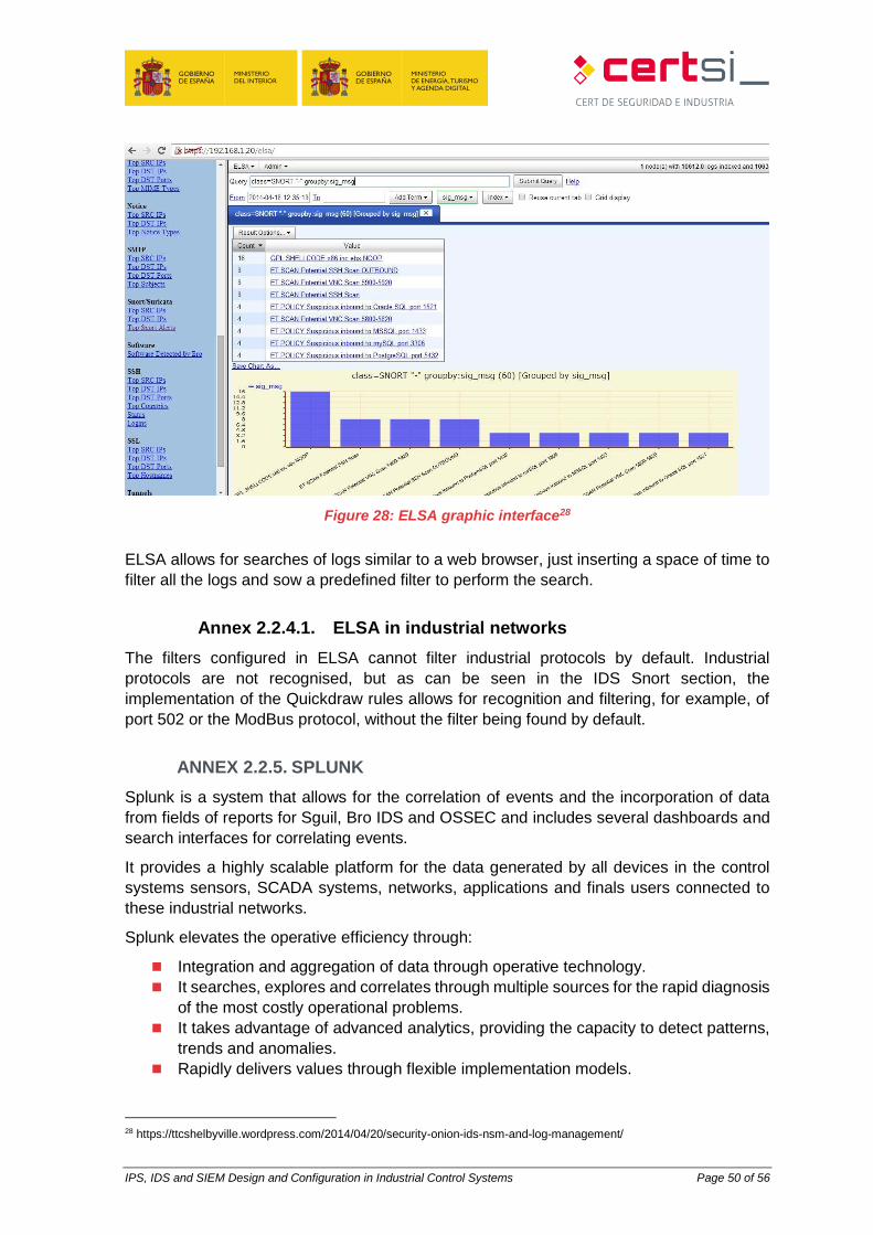
IPS, IDS and SIEM Design and Configuration in Industrial Control Systems Page 50 of 56
Figure 28: ELSA graphic interface28
ELSA allows for searches of logs similar to a web browser, just inserting a space of time to
filter all the logs and sow a predefined filter to perform the search.
Annex 2.2.4.1. ELSA in industrial networks
The filters configured in ELSA cannot filter industrial protocols by default. Industrial
protocols are not recognised, but as can be seen in the IDS Snort section, the
implementation of the Quickdraw rules allows for recognition and filtering, for example, of
port 502 or the ModBus protocol, without the filter being found by default.
ANNEX 2.2.5. SPLUNK
Splunk is a system that allows for the correlation of events and the incorporation of data
from fields of reports for Sguil, Bro IDS and OSSEC and includes several dashboards and
search interfaces for correlating events.
It provides a highly scalable platform for the data generated by all devices in the control
systems sensors, SCADA systems, networks, applications and finals users connected to
these industrial networks.
Splunk elevates the operative efficiency through:
Integration and aggregation of data through operative technology.
It searches, explores and correlates through multiple sources for the rapid diagnosis
of the most costly operational problems.
It takes advantage of advanced analytics, providing the capacity to detect patterns,
trends and anomalies.
Rapidly delivers values through flexible implementation models.
28 https://ttcshelbyville.wordpress.com/2014/04/20/security-onion-ids-nsm-and-log-management/
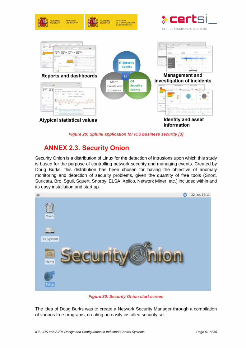
IPS, IDS and SIEM Design and Configuration in Industrial Control Systems Page 51 of 56
Figure 29: Splunk application for ICS business security [3]
ANNEX 2.3. Security Onion
Security Onion is a distribution of Linux for the detection of intrusions upon which this study
is based for the purpose of controlling network security and managing events. Created by
Doug Burks, this distribution has been chosen for having the objective of anomaly
monitoring and detection of security problems, given the quantity of free tools (Snort,
Suricata, Bro, Sguil, Squert, Snorby, ELSA, Xplico, Network Miner, etc.) included within and
its easy installation and start up.
Figure 30: Security Onion start screen
The idea of Doug Burks was to create a Network Security Manager through a compilation
of various free programs, creating an easily installed security set.
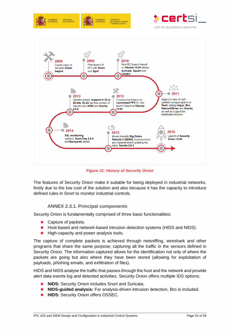
IPS, IDS and SIEM Design and Configuration in Industrial Control Systems Page 52 of 56
Figure 31: History of Security Onion
The features of Security Onion make it suitable for being deployed in industrial networks,
firstly due to the low cost of the solution and also because it has the capacity to introduce
defined rules in Snort to monitor industrial controls.
ANNEX 2.3.1. Principal components
Security Onion is fundamentally comprised of three basic functionalities:
Capture of packets.
Host-based and network-based intrusion detection systems (HIDS and NIDS).
High-capacity and power analysis tools.
The capture of complete packets is achieved through netsniffing, wireshark and other
programs that share the same purpose; capturing all the traffic in the sensors defined in
Security Onion. The information captured allows for the identification not only of where the
packets are going but also where they have been stored (allowing for exploitation of
payloads, phishing emails, and exfiltration of files).
HIDS and NIDS analyse the traffic that passes through the host and the network and provide
alert data events log and detected activities. Security Onion offers multiple IDS options:
NIDS: Security Onion includes Snort and Suricata.
NIDS-guided analysis: For analysis-driven intrusion detection, Bro is included.
HIDS: Security Onion offers OSSEC.
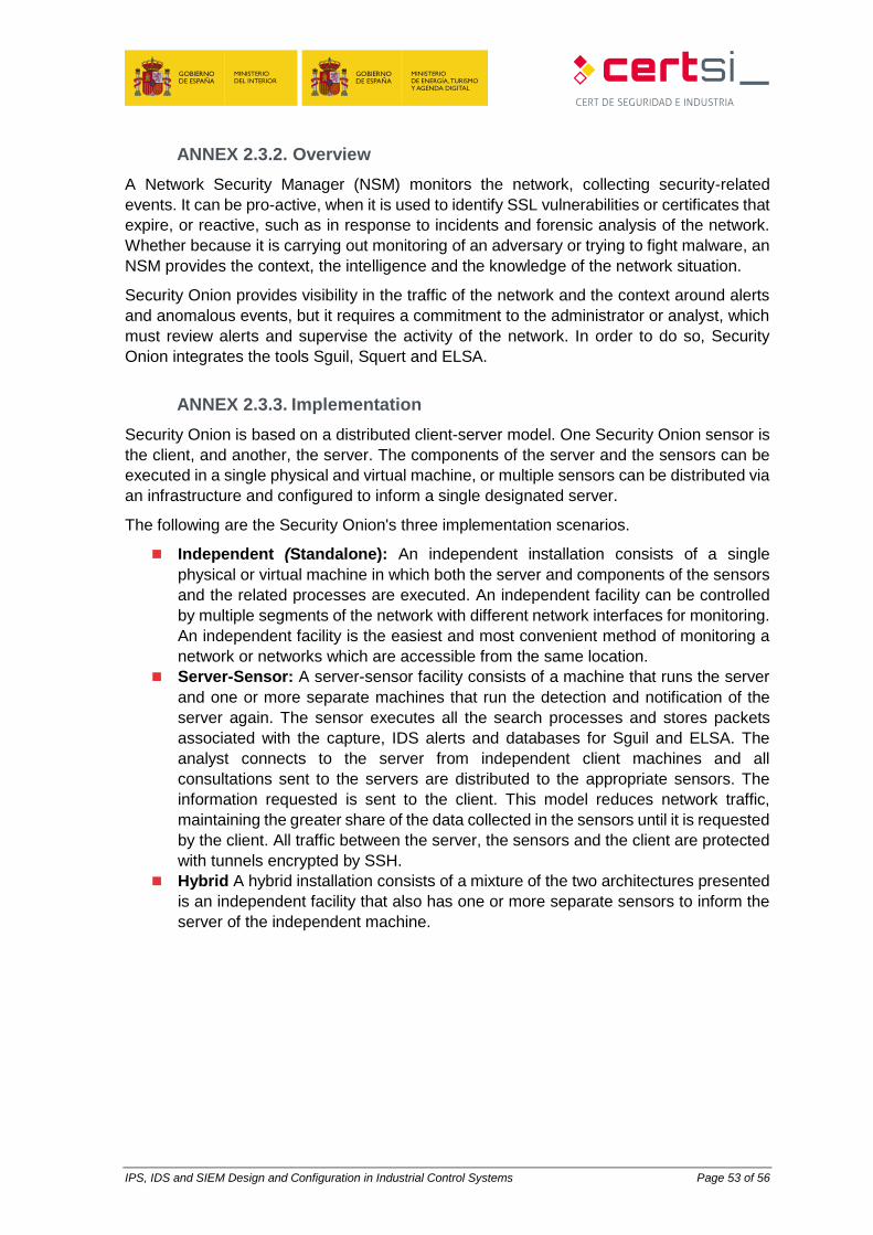
IPS, IDS and SIEM Design and Configuration in Industrial Control Systems Page 53 of 56
ANNEX 2.3.2. Overview
A Network Security Manager (NSM) monitors the network, collecting security-related
events. It can be pro-active, when it is used to identify SSL vulnerabilities or certificates that
expire, or reactive, such as in response to incidents and forensic analysis of the network.
Whether because it is carrying out monitoring of an adversary or trying to fight malware, an
NSM provides the context, the intelligence and the knowledge of the network situation.
Security Onion provides visibility in the traffic of the network and the context around alerts
and anomalous events, but it requires a commitment to the administrator or analyst, which
must review alerts and supervise the activity of the network. In order to do so, Security
Onion integrates the tools Sguil, Squert and ELSA.
ANNEX 2.3.3. Implementation
Security Onion is based on a distributed client-server model. One Security Onion sensor is
the client, and another, the server. The components of the server and the sensors can be
executed in a single physical and virtual machine, or multiple sensors can be distributed via
an infrastructure and configured to inform a single designated server.
The following are the Security Onion's three implementation scenarios.
Independent (Standalone): An independent installation consists of a single
physical or virtual machine in which both the server and components of the sensors
and the related processes are executed. An independent facility can be controlled
by multiple segments of the network with different network interfaces for monitoring.
An independent facility is the easiest and most convenient method of monitoring a
network or networks which are accessible from the same location.
Server-Sensor: A server-sensor facility consists of a machine that runs the server
and one or more separate machines that run the detection and notification of the
server again. The sensor executes all the search processes and stores packets
associated with the capture, IDS alerts and databases for Sguil and ELSA. The
analyst connects to the server from independent client machines and all
consultations sent to the servers are distributed to the appropriate sensors. The
information requested is sent to the client. This model reduces network traffic,
maintaining the greater share of the data collected in the sensors until it is requested
by the client. All traffic between the server, the sensors and the client are protected
with tunnels encrypted by SSH.
Hybrid A hybrid installation consists of a mixture of the two architectures presented
is an independent facility that also has one or more separate sensors to inform the
server of the independent machine.

IPS, IDS and SIEM Design and Configuration in Industrial Control Systems Page 54 of 56
BIBLIOGRAPHY
[1] Optimización de sistemas de detección de intrusos en red utilizando técnicas computacionales avanzadas. Gómez López, Julio. 10/2009. ISBN: 9788482409313
[2] Introduction to network Security. Debabrata Dash. http://www.slideshare.net/patelvinil/network-security-52257967
[3] https://conf.splunk.com/session/2015/conf2015_TMcCorkle_Splunk_SecurityCompliance_SplunkForIndustrialControl.pdf
[4] IDS gratuitos, pros y contras:
https://www.upguard.com/articles/top-free-network-based-intrusion-detection-systems-ids-for-the-enterprise
[5] Añade OSSEC y OpenWIPS-NG
http://searchsecurity.techtarget.com/tip/Top-five-free-enterprise-network-intrusion-detection-tools
[6] Free Intrusion Detection (IDS) and Prevention (IPS) Software
http://netsecurity.about.com/od/intrusiondetectionid1/a/aafreeids.htm [7] Introduction to Intrusion Detection Systems (IDS)
http://netsecurity.about.com/cs/hackertools/a/aa030504.htm [8] What is the Difference Between an IPS and a Web Application Firewall?
https://www.sans.org/security-resources/idfaq/what-is-the-difference-between-an-ips-and-a-web-application-firewall/1/25
[9] Intrusion Prevention Systems: the Next Step in the Evolution of IDS.
https://www.symantec.com/connect/articles/intrusion-prevention-systems-next-step-evolution-ids
[10] Adaptación del IDS/IPS Suricata para que se pueda convertir en una solución empresarial
https://www.dspace.espol.edu.ec/bitstream/123456789/19502/1/Diapositivas_tesina.pdf [11] Proyecto final de carrera
http://www.adminso.es/images/0/03/Pfc_Carlos_cap1.pdf [12] IDS vs IPS módulo ciberseguridad
http://www.cybsec.com/upload/ESPE_IDS_vs_IPS.pdf [13] Herramientas de Detección y Prevención de Intrusos
http://www.jessland.net/JISK/IDS_IPS/Tools_(Es).php [14] IDS e IPS Universidad Politécnica
http://www.criptored.upm.es/guiateoria/gt_m142w.htm [15] What is the Difference Between an IPS and a Web Application Firewall?
https://www.sans.org/security-resources/idfaq/what-is-the-difference-between-an-ips-and-a-web-application-firewall/1/25
[16] Introducción a las Web Application Firewalls (WAF)
http://wiki.elhacker.net/seguridad/web/introduccion-a-los-web-application-firewalls-waf [17] A Practical Guide to Security Assessments. Sudhanshu Kairab. 2004
[18] Advances in swarm and computational intelligence: 6th International Conference, ICSI 2015
held in conjunction with the second BRICS Congress, CCI 2015, Beijing, June 25-28, 2015,
Proceedings. Part II
[19] What is The Role of a SIEM in Detecting Events of Interest?
https://www.sans.org/security-resources/idfaq/what-is-the-role-of-a-siem-in-detecting-events-of-interest/5/10
[20] SIEM
https://securitcrs.wordpress.com/knowledge-base/siem-security-information-and-event-management/
[21] A Guide to Security Information and Event Management
http://www.tomsitpro.com/articles/siem-solutions-guide,2-864.html [22] Suricata
https://redmine.openinfosecfoundation.org/projects/suricata/wiki/Suricata_User_Guide [23] Security Analytics with Big Data,
https://securosis.com/assets/library/reports/SecurityAnalytics_BigData_V2.pdf
IPS, IDS and SIEM Design and Configuration in Industrial Control Systems Page 55 of 56
[24] Splunk & Pcap
https://www.sans.org/reading-room/whitepapers/detection/security-analytics-fun-splunk-packet-capture-file-pcap-34580
[25] Introduction to wireless intrusion prevention systems in the enterprise
http://searchsecurity.techtarget.com/feature/Introduction-to-wireless-intrusion-prevention-systems-in-the-enterprise
[26] Comparing the top wireless intrusion prevention systems
http://searchsecurity.techtarget.com/feature/Comparing-the-top-wireless-intrusion-prevention-systems
[27] Snort vs Suricata
http://wiki.aanval.com/wiki/Snort_vs_Suricata [28] Security Onion - Doug Burks youtube channel
[29] Squert
http://www.squertproject.org/ [30] OSSEC Architecture. https://ossec.github.io/docs/manual/ossec-architecture.html
[31] Quickdraw SCADA IDS. http://www.digitalbond.com/tools/quickdraw/
[32] Bro. https://en.wikipedia.org/wiki/Bro_(software)
[33] IEC 62443-2-1. Industrial communication networks – Network and system security – Part 2-
1: Establishing an industrial automation and control system security program
[34] Snorby
https://github.com/Snorby/snorby
[35] Barnyard2
https://github.com/firnsy/barnyard2

IPS, IDS and SIEM Design and Configuration in Industrial Control Systems Page 56 of 56


![08-IDS IPS 2 [Compatibility Mode]](https://img.pdfslide.us/doc/110x75/547f69ca5906b508298b45ae/08-ids-ips-2-compatibility-mode.jpg)