Embed Size (px)
Citation preview
INTERNATIONAL JOURNAL OF PROFESSIONAL ENGINEERING STUDIES Volume 9 /Issue 2 / SEP 2017
IJPRES
DESIGN AND CFD ANALYSIS OF CONVERGENT AND DIVERGENT NOZZLE
1P.VINOD KUMAR,2B.KISHORE KUMAR 1 PG Scholar, Department ofMECH,NALANDA INSTITUTION OF ENGINEERING AND TECHNOLOGY
KantepudiSattenapalli, GUNTUR,A.P, India, Pin: 522438 2 Assistant Professor, Department of MECH,NALANDA INSTITUTION OF ENGINEERING AND
TECHNOLOGY,Kantepudi,Sattenapalli, GUNTUR,A.P, India, Pin: 522438
Abstract
Nozzle is a device designed to control the
rate of flow, speed, direction, mass, shape, and/or the
pressure of the Fluid that exhaust from them.
Convergent-divergent nozzle is the most commonly
used nozzle since in using it the propellant can be
heated incombustion chamber. In this project we
designed a new Tri-nozzle to increase the velocity of
fluids flowing through it. It is designed based on
basic convergent-Divergent nozzle to have same
throat area, length, convergent angle and divergent
angle as single nozzle. But the design of Tri-nozzle is
optimized to have high expansion co-efficient than
single nozzle without altering the divergent angle. In
the present paper, flow through theTri-nozzle and
convergent divergent nozzle study is carried out by
using SOLID WORKS PREMIUM 2014.The nozzle
geometry modeling and mesh generation has been
done using SOLID WORKS CFD Software.
Computational results are in goodacceptance with the
experimental results taken from the literature.
1. Introduction to nozzle
Swedish engineer of French descent who, in trying to
develop a more efficient steam engine, designed a
turbine that was turned by jets of steam. The critical
component – the one in which heat energy of the hot
high-pressure steam from the boiler was converted
into kinetic energy – was the nozzle from which the
jet blew onto the wheel. De Laval found that the most
efficient conversion occurred when the nozzle first
narrowed, increasing the speed of the jet to the speed
of sound, and then expanded again. Above the speed
of sound (but not below it) this expansion caused a
further increase in the speed of the jet and led to a
very efficient conversion of heat energy to motion.
The theory of air resistance was first proposed by Sir
Isaac Newton in 1726. According to him, an
aerodynamic force depends on the density and
velocity of the fluid, and the shape and the size of the
displacing object. Newton’s theory was soon
followed by other theoretical solution of fluid motion
problems. All these were restricted to flow under
idealized conditions, i.e. air was assumed to posses
constant density and to move in response to pressure
and inertia. Nowadays steam turbines are the
preferredpower source of electric power stations and
large ships, although they usually have a different
design-to make best use of the fast steam jet, de
Laval’s turbine had to run at an impractically high
speed. But for rockets the de Laval nozzle was just
what was needed.
A nozzle is a device designed to control the
direction or characteristics of a fluid flow (especially
to increase velocity) as it exits (or enters) an enclosed
chamber. A nozzle is often a pipe or tube of varying
cross sectional area and it can be used to direct or
modify the flow of a fluid (liquid or gas). Nozzles are
frequently used to control the rate of flow, speed,
direction, mass, shape, and/or the pressure of the
stream that emerges from them. A jet exhaust
produces a net thrust from the energy obtained from
INTERNATIONAL JOURNAL OF PROFESSIONAL ENGINEERING STUDIES Volume 9 /Issue 2 / SEP 2017
IJPRES
combusting fuel which is added to the inducted air.
This hot air is passed through a high speed nozzle, a
propelling nozzle which enormously increases its
kinetic energy. The goal of nozzle is to increase the
kinetic energy of the flowing medium at the expense
of its pressure and internal energy. Nozzles can be
described as convergent (narrowing down from a
wide diameter to a smaller diameter in the direction
of the flow) or divergent (expanding from a smaller
diameter to a larger one). A de Laval nozzle has a
convergent section followed by a divergent section
and is often called a convergent-divergent nozzle
("con-di nozzle"). Convergent nozzles accelerate
subsonic fluids. If the nozzle pressure ratio is high
enough the flow will reach sonic velocity at the
narrowest point (i.e. the nozzle throat). In this
situation, the nozzle is said to be choked.
Increasing the nozzle pressure ratio further
will not increase the throat Mach number beyond
unity. Downstream (i.e. external to the nozzle) the
flow is free to expand to supersonic velocities. Note
that the Mach 1 can be a very high speed for a hot
gas; since the speed of sound varies as the square root
of absolute temperature. Thus the speed reached at a
nozzle throat can be far higher than the speed of
sound at sea level. This fact is used extensively in
rocketry where hypersonic flows are required, and
where propellant mixtures are deliberately chosen to
further increase the sonic speed. Divergent nozzles
slow fluids, if the flow is subsonic, but accelerate
sonic or supersonic fluids. Convergent-divergent
nozzles can therefore accelerate fluids that have
choked in the convergent section to supersonic
speeds. This CD process is more efficient than
allowing a convergent nozzle to expand
supersonically externally. The shape of the divergent
section also ensures that the direction of the escaping
gases is directly backwards, as any sideways
component would not contribute to thrust.
2. Literature review
CONVERGENT-DIVERGENT nozzle is
designed for attaining speeds that are greater than
speed of sound. the design of this nozzle came from
the area-velocity relation (dA/dV)=-(A/V)(1-M^2) M
is the Mach number ( which means ratio of local
speed of flow to the local speed of sound) A is area
and V is velocity The following information can be
derived from the area-velocity relation –
1. For incompressible flow limit, i.e. for M tends to
zero, AV = constant. This is the famous volume
conservation equation or continuity equation for
incompressible flow.
2. For M < 1, a decrease in area results in increase of
velocity and vice vera. Therefore, the velocity
increases in a convergent duct and decreases in a
Divergent duct. This result for compressible subsonic
flows is the same as that for incompressible flow.
3. For M > 1, an increase in area results in increases
of velocity and vice versa, i.e. the velocity increases
in a divergent duct and decreases in a convergent
duct. This is directly opposite to the behavior of
subsonic flow in divergent and convergent ducts.
4. For M = 1, dA/A = 0, which implies that the
location where the Mach number is unity, the area of
the passage is either minimum or maximum. We can
easily show that the minimum in area is the only
physically realistic solution.
One important point is that to attain supersonic
speeds we have to maintain favorable pressure ratios
across the nozzle. One example is attain just sonic
speeds at the throat, pressure ratio to e maintained is
(Pthroat / P inlet)=0.528.
INTERNATIONAL JOURNAL OF PROFESSIONAL ENGINEERING STUDIES Volume 9 /Issue 2 / SEP 2017
IJPRES
Table1: speeds vs mach number
Reg
ime
Ma
ch
Subs
onic
<1.0
Trans
onic
0.8-
1.2
So
nic
1.0
Super
sonic
1.0-
5.0
Hyper
sonic
5.0-
10.0
High-
hyper
sonic
>10.0
From table.1 at transonic speeds, the flow field
around the object includes both sub- and supersonic
parts. The transonic period begins when first zones of
M>1 flow appear around the object. In case of an
airfoil (such as an aircraft's wing), this typically
happens above the wing. Supersonic flow can
decelerate back to subsonic only in a normal shock;
this typically happens before the trailing edge. (Fig.a)
As the speed increases, the zone of M>1 flow
increases towards both leading and trailing edges. As
M=1 is reached and passed, the normal shock reaches
the trailing edge and becomes a weak oblique shock:
the flow decelerates over the shock, but remains
supersonic. A normal shock is created ahead of the
object, and the only subsonic zone in the flow field is
a small area around the object's leading edge
The governing continuity, momentum, and energy
equations for this quasi one-dimensional, steady,
isentropic flow can be expressed, respectively
3. Types of nozzles
Types of nozzles are several types. They could be
based on either speed or shape.
a. Based on speed The basic types of nozzles can
be differentiated as
• Spray nozzles
• Ramjet nozzles
b. Based on shape The basic types of nozzles can
be differentiated as
• Conical
• Bell
• Annular
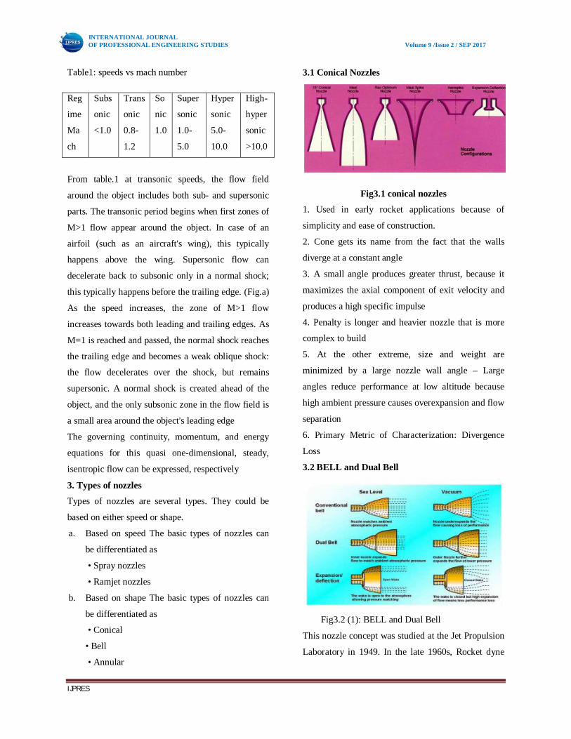
3.1 Conical Nozzles
Fig3.1 conical nozzles
1. Used in early rocket applications because of
simplicity and ease of construction.
2. Cone gets its name from the fact that the walls
diverge at a constant angle
3. A small angle produces greater thrust, because it
maximizes the axial component of exit velocity and
produces a high specific impulse
4. Penalty is longer and heavier nozzle that is more
complex to build
5. At the other extreme, size and weight are
minimized by a large nozzle wall angle – Large
angles reduce performance at low altitude because
high ambient pressure causes overexpansion and flow
separation
6. Primary Metric of Characterization: Divergence
Loss
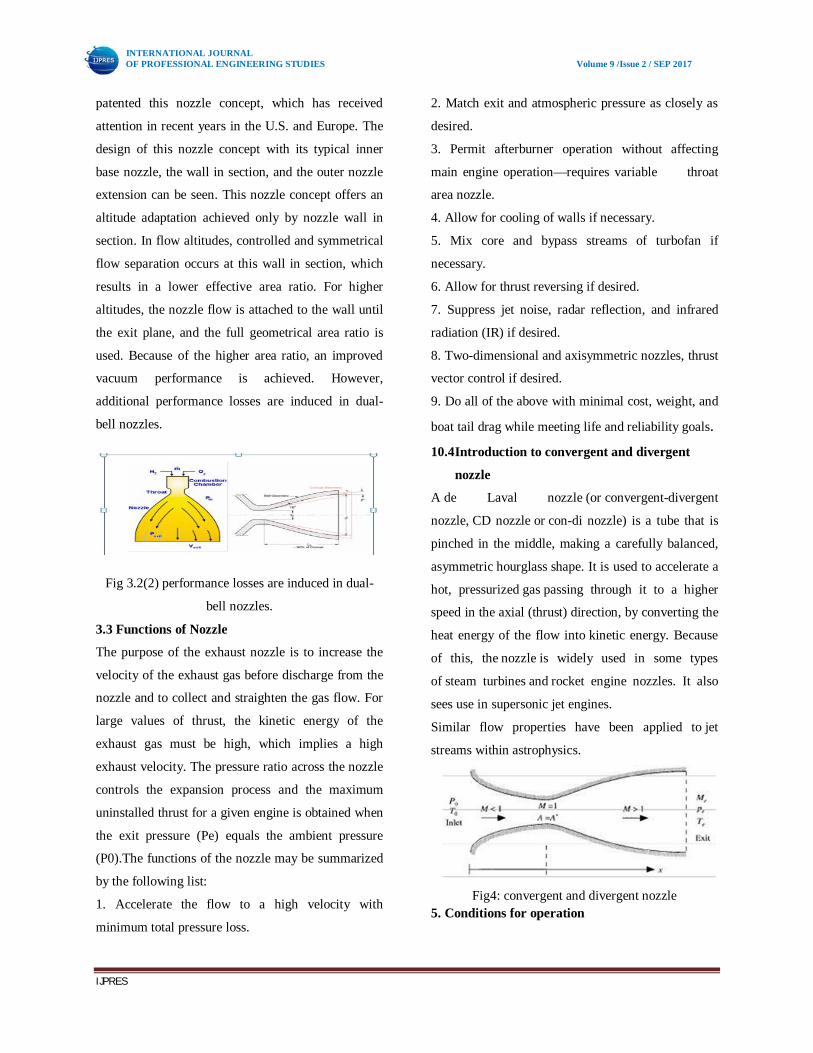
3.2 BELL and Dual Bell
Fig3.2 (1): BELL and Dual Bell
This nozzle concept was studied at the Jet Propulsion
Laboratory in 1949. In the late 1960s, Rocket dyne
INTERNATIONAL JOURNAL OF PROFESSIONAL ENGINEERING STUDIES Volume 9 /Issue 2 / SEP 2017
IJPRES
patented this nozzle concept, which has received
attention in recent years in the U.S. and Europe. The
design of this nozzle concept with its typical inner
base nozzle, the wall in section, and the outer nozzle
extension can be seen. This nozzle concept offers an
altitude adaptation achieved only by nozzle wall in
section. In flow altitudes, controlled and symmetrical
flow separation occurs at this wall in section, which
results in a lower effective area ratio. For higher
altitudes, the nozzle flow is attached to the wall until
the exit plane, and the full geometrical area ratio is
used. Because of the higher area ratio, an improved
vacuum performance is achieved. However,
additional performance losses are induced in dual-
bell nozzles.
Fig 3.2(2) performance losses are induced in dual-
bell nozzles.
3.3 Functions of Nozzle
The purpose of the exhaust nozzle is to increase the
velocity of the exhaust gas before discharge from the
nozzle and to collect and straighten the gas flow. For
large values of thrust, the kinetic energy of the
exhaust gas must be high, which implies a high
exhaust velocity. The pressure ratio across the nozzle
controls the expansion process and the maximum
uninstalled thrust for a given engine is obtained when
the exit pressure (Pe) equals the ambient pressure
(P0).The functions of the nozzle may be summarized
by the following list:
1. Accelerate the flow to a high velocity with
minimum total pressure loss.
2. Match exit and atmospheric pressure as closely as
desired.
3. Permit afterburner operation without affecting
main engine operation—requires variable throat
area nozzle.
4. Allow for cooling of walls if necessary.
5. Mix core and bypass streams of turbofan if
necessary.
6. Allow for thrust reversing if desired.
7. Suppress jet noise, radar reflection, and infrared
radiation (IR) if desired.
8. Two-dimensional and axisymmetric nozzles, thrust
vector control if desired.
9. Do all of the above with minimal cost, weight, and
boat tail drag while meeting life and reliability goals. 10.4 Introduction to convergent and divergent
nozzle
A de Laval nozzle (or convergent-divergent
nozzle, CD nozzle or con-di nozzle) is a tube that is
pinched in the middle, making a carefully balanced,
asymmetric hourglass shape. It is used to accelerate a
hot, pressurized gas passing through it to a higher
speed in the axial (thrust) direction, by converting the
heat energy of the flow into kinetic energy. Because
of this, the nozzle is widely used in some types
of steam turbines and rocket engine nozzles. It also
sees use in supersonic jet engines.
Similar flow properties have been applied to jet
streams within astrophysics.
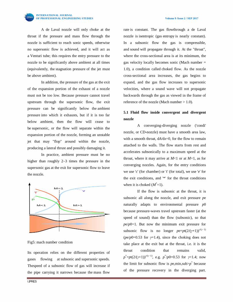
Fig4: convergent and divergent nozzle
5. Conditions for operation
INTERNATIONAL JOURNAL OF PROFESSIONAL ENGINEERING STUDIES Volume 9 /Issue 2 / SEP 2017
IJPRES
A de Laval nozzle will only choke at the
throat if the pressure and mass flow through the
nozzle is sufficient to reach sonic speeds, otherwise
no supersonic flow is achieved, and it will act as
a Venturi tube; this requires the entry pressure to the
nozzle to be significantly above ambient at all times
(equivalently, the stagnation pressure of the jet must
be above ambient).
In addition, the pressure of the gas at the exit
of the expansion portion of the exhaust of a nozzle
must not be too low. Because pressure cannot travel
upstream through the supersonic flow, the exit
pressure can be significantly below the ambient
pressure into which it exhausts, but if it is too far
below ambient, then the flow will cease to
be supersonic, or the flow will separate within the
expansion portion of the nozzle, forming an unstable
jet that may "flop" around within the nozzle,
producing a lateral thrust and possibly damaging it.
In practice, ambient pressure must be no
higher than roughly 2–3 times the pressure in the
supersonic gas at the exit for supersonic flow to leave
the nozzle.
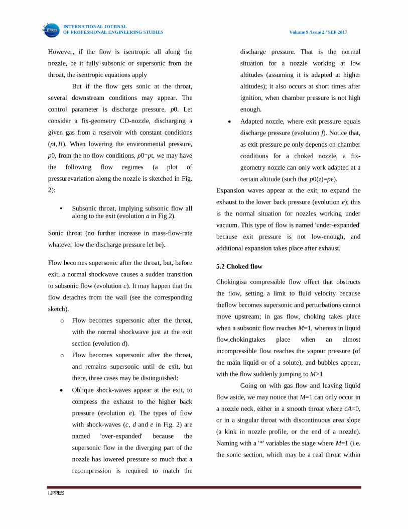
Fig5: mach number condition
Its operation relies on the different properties of
gases flowing at subsonic and supersonic speeds.
Thespeed of a subsonic flow of gas will increase if
the pipe carrying it narrows because the mass flow
rate is constant. The gas flowthrough a de Laval
nozzle is isentropic (gas entropy is nearly constant).
In a subsonic flow the gas is compressible,
and sound will propagate through it. At the "throat",
where the cross-sectional area is at its minimum, the
gas velocity locally becomes sonic (Mach number =
1.0), a condition called choked flow. As the nozzle
cross-sectional area increases, the gas begins to
expand, and the gas flow increases to supersonic
velocities, where a sound wave will not propagate
backwards through the gas as viewed in the frame of
reference of the nozzle (Mach number > 1.0).
5.1 Fluid flow inside convergent and divergent
nozzle
A converging-diverging nozzle ('condi'
nozzle, or CD-nozzle) must have a smooth area law,
with a smooth throat, dA/dx=0, for the flow to remain
attached to the walls. The flow starts from rest and
accelerates subsonically to a maximum speed at the
throat, where it may arrive at M<1 or at M=1, as for
converging nozzles. Again, for the entry conditions
we use 'c' (for chamber) or 't' (for total), we use 'e' for
the exit conditions, and '*' for the throat conditions
when it is choked (M*=1).
If the flow is subsonic at the throat, it is
subsonic all along the nozzle, and exit pressure pe
naturally adapts to environmental pressure p0
because pressure-waves travel upstream faster (at the
speed of sound) than the flow (subsonic), so that
pe/p0=1. But now the minimum exit pressure for
subsonic flow is no longer pe=pt(2/(γ+1))γ/(γ−1)
(pe/p0=0.53 for γ=1.4), since the choking does not
take place at the exit but at the throat, i.e. it is the
throat condition that remains valid,
p*=pt(2/(γ+1))γ/(γ−1), e.g. p*/p0=0.53 for γ=1.4; now
the limit for subsonic flow is pe,min,sub>p* because
of the pressure recovery in the diverging part.
INTERNATIONAL JOURNAL OF PROFESSIONAL ENGINEERING STUDIES Volume 9 /Issue 2 / SEP 2017
IJPRES
However, if the flow is isentropic all along the
nozzle, be it fully subsonic or supersonic from the
throat, the isentropic equations apply
But if the flow gets sonic at the throat,
several downstream conditions may appear. The
control parameter is discharge pressure, p0. Let
consider a fix-geometry CD-nozzle, discharging a
given gas from a reservoir with constant conditions
(pt,Tt). When lowering the environmental pressure,
p0, from the no flow conditions, p0=pt, we may have
the following flow regimes (a plot of
pressurevariation along the nozzle is sketched in Fig.
2):
• Subsonic throat, implying subsonic flow all along to the exit (evolution a in Fig 2).
Sonic throat (no further increase in mass-flow-rate
whatever low the discharge pressure let be).
Flow becomes supersonic after the throat, but, before
exit, a normal shockwave causes a sudden transition
to subsonic flow (evolution c). It may happen that the
flow detaches from the wall (see the corresponding
sketch).
o Flow becomes supersonic after the throat,
with the normal shockwave just at the exit
section (evolution d).
o Flow becomes supersonic after the throat,
and remains supersonic until de exit, but
there, three cases may be distinguished:
Oblique shock-waves appear at the exit, to
compress the exhaust to the higher back
pressure (evolution e). The types of flow
with shock-waves (c, d and e in Fig. 2) are
named 'over-expanded' because the
supersonic flow in the diverging part of the
nozzle has lowered pressure so much that a
recompression is required to match the
discharge pressure. That is the normal
situation for a nozzle working at low
altitudes (assuming it is adapted at higher
altitudes); it also occurs at short times after
ignition, when chamber pressure is not high
enough.
Adapted nozzle, where exit pressure equals
discharge pressure (evolution f). Notice that,
as exit pressure pe only depends on chamber
conditions for a choked nozzle, a fix-
geometry nozzle can only work adapted at a
certain altitude (such that p0(z)=pe).
Expansion waves appear at the exit, to expand the
exhaust to the lower back pressure (evolution e); this
is the normal situation for nozzles working under
vacuum. This type of flow is named 'under-expanded'
because exit pressure is not low-enough, and
additional expansion takes place after exhaust.
5.2 Choked flow
Chokingisa compressible flow effect that obstructs
the flow, setting a limit to fluid velocity because
theflow becomes supersonic and perturbations cannot
move upstream; in gas flow, choking takes place
when a subsonic flow reaches M=1, whereas in liquid
flow,chokingtakes place when an almost
incompressible flow reaches the vapour pressure (of
the main liquid or of a solute), and bubbles appear,
with the flow suddenly jumping to M>1
Going on with gas flow and leaving liquid
flow aside, we may notice that M=1 can only occur in
a nozzle neck, either in a smooth throat where dA=0,
or in a singular throat with discontinuous area slope
(a kink in nozzle profile, or the end of a nozzle).
Naming with a '*' variables the stage where M=1 (i.e.
the sonic section, which may be a real throat within
INTERNATIONAL JOURNAL OF PROFESSIONAL ENGINEERING STUDIES Volume 9 /Issue 2 / SEP 2017
IJPRES
the nozzle or at some extrapolated imaginary throat
downstream of a subsonic nozzle.
5.3 Area ratio
Nozzle area ratio ε (or nozzle expansion
ratio) is defined as nozzle exit area divided by throat
area, ε≡Ae/A*, in converging-diverging nozzles, or
divided by entry area in converging nozzles. Notice
that ε sodefined is ε>1, but sometimes the inverse is
also named 'area ratio' (this contraction area ratio is
bounded between 0 and 1); however, although no
confusion is possible when quoting a value (if it is >1
refers to Ae/A*, and if it is <1 refers to A*/Ae), one
must be explicit when saying 'increasing area ratio'
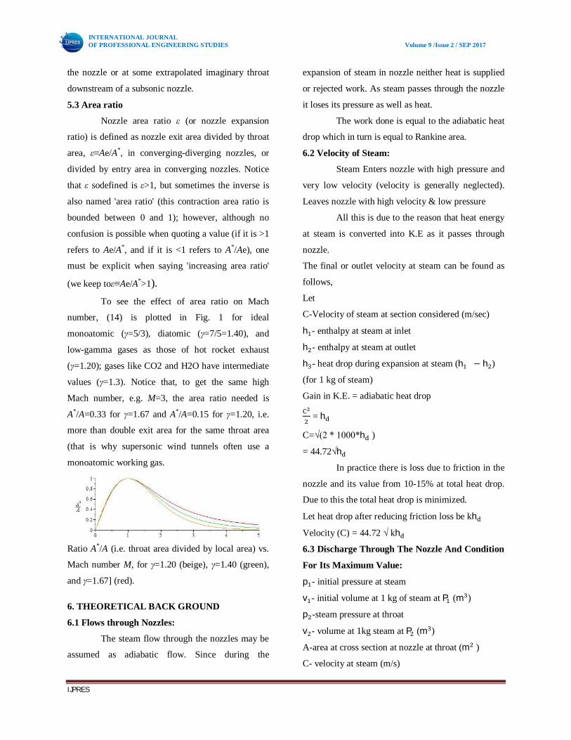
(we keep toε≡Ae/A*>1). To see the effect of area ratio on Mach
number, (14) is plotted in Fig. 1 for ideal
monoatomic (γ=5/3), diatomic (γ=7/5=1.40), and
low-gamma gases as those of hot rocket exhaust
(γ=1.20); gases like CO2 and H2O have intermediate
values (γ=1.3). Notice that, to get the same high
Mach number, e.g. M=3, the area ratio needed is
A*/A=0.33 for γ=1.67 and A*/A=0.15 for γ=1.20, i.e.
more than double exit area for the same throat area
(that is why supersonic wind tunnels often use a
monoatomic working gas.
Ratio A*/A (i.e. throat area divided by local area) vs.
Mach number M, for γ=1.20 (beige), γ=1.40 (green),
and γ=1.67] (red).
6. THEORETICAL BACK GROUND
6.1 Flows through Nozzles:
The steam flow through the nozzles may be
assumed as adiabatic flow. Since during the
expansion of steam in nozzle neither heat is supplied
or rejected work. As steam passes through the nozzle
it loses its pressure as well as heat.
The work done is equal to the adiabatic heat
drop which in turn is equal to Rankine area.
6.2 Velocity of Steam:
Steam Enters nozzle with high pressure and
very low velocity (velocity is generally neglected).
Leaves nozzle with high velocity & low pressure
All this is due to the reason that heat energy
at steam is converted into K.E as it passes through
nozzle.
The final or outlet velocity at steam can be found as
follows,
Let
C-Velocity of steam at section considered (m/sec)
h - enthalpy at steam at inlet
h - enthalpy at steam at outlet
h - heat drop during expansion at steam (h − h )
(for 1 kg of steam)
Gain in K.E. = adiabatic heat drop
= h
C=√(2 * 1000*h )
= 44.72√h
In practice there is loss due to friction in the
nozzle and its value from 10-15% at total heat drop.
Due to this the total heat drop is minimized.
Let heat drop after reducing friction loss be kh
Velocity (C) = 44.72 √ kh
6.3 Discharge Through The Nozzle And Condition
For Its Maximum Value:
p - initial pressure at steam
v - initial volume at 1 kg of steam at P (m )
p -steam pressure at throat
v - volume at 1kg steam at P (m )
A-area at cross section at nozzle at throat (m )
C- velocity at steam (m/s)
INTERNATIONAL JOURNAL OF PROFESSIONAL ENGINEERING STUDIES Volume 9 /Issue 2 / SEP 2017
IJPRES
Steam passing through nozzle follows adiabatic
process in which
p푣 = constant
n= 1.135 for saturated steam
n= 1.3 for super saturated steam
for wet steam the value at ‘n’ can be calculated by
Dr.Zenner’s equation
n= 1.035 + 0.1x
x- dryness fraction at steam (initial)
workdone per 1 kg at steam during the cycle
(Rankine cycle)
W = (p v - p v )
Already we know
Gain in K.E = adiabatic heat drop
= workdone during Ranlinecycl
Per 1 kg
= (p v - p v )
= p v (1- ) ………….(1)
Also
p 푣 = p 푣
= (vv ) => = (p p ) ………(2)
=>v = v (p p ) ……..(3)
equation 2 in 1
= p v (1- )
= p v [1- (p p ) ]
= p v [1- (pp ) ]
= p v [1- (p p ) ]
푐 = 2 { p v [1- (p p ) ]}
C = √ (2{ 풏풏 ퟏ
퐩ퟏ퐯ퟏ [1- (퐩ퟐ 퐩ퟏ)풏 ퟏ풏 ]}
If m is the mass of steam discharged in kg/sec
m =
by substituting value of c &v we get
m = ( )
√( 2{ p v [1- (p p ) ]})
m = √ (2{ p v [(p p ) - (p p ) ]})
it is obvious form above equation that there is only
one value at the ratio (critical pressure ratio) p p
which will produce max discharge
and this can be obtained by differenciating m with
respect to p p and equating to zero
and other quantities except pp remains here
constant
=> [(p p ) - (p p ) ] = 0
=> [ (pp ) - ( )(p
p ) ]
=>(pp ) = ( ) (p
p )
=>(pp ) = (푛 + 1
2)
pp = (푛 + 1
2)
pp = (2 푛 + 1)
Hence discharge through the nozzle will be
maximum when critical pressure ratio is
= pp = (2 푛 + 1)
By substituting p p value in mass equation we get
the maximum discharge
m = √ (2{ p v [(p p ) - (p p ) ]})
INTERNATIONAL JOURNAL OF PROFESSIONAL ENGINEERING STUDIES Volume 9 /Issue 2 / SEP 2017
IJPRES
= √ (2{ p v [[ (2푛 + 1) ] –
[(2 푛 + 1) ] ]})
= √ (2{ p v [[ (2푛 + 1) –
[(2 푛 + 1) ]})
= √ (2{ p v [[ (2푛 + 1) –
[(2 푛 + 1) − 1]})
= √ (2{ p v [[ (2푛 + 1) –
[(2 푛 + 1) − 1]]})
= √ (2{ p v [ (2푛 + 1) –
[( − 1)] })
= √ (2{ p v [ (2푛 + 1) –
( )]})
푚 = A √ n ( ) [(2푛 + 1)
By substituting p p = (2푛 + 1) in equation c
we get 퐶
퐶 = √ 2( ) p v [1- ((2푛 + 1) )
= √ 2( ) p v [1- ]
= √ 2( ) p v ( )
퐶 = √ 2( ) p v
From maximum equation, it is evident that the
maximum mass flow depends only on the inlet
conditions ( p v ) and the throat area.and it is
independent at final pressure at steam i.e., exit at the
nozzle
Note: p푣 = constant
= constant
= constant
pp = ( ) = ( )
Specific volume v = v (p p )
Apparent temperature 푇 = 푇 (p p )
Nozzle efficiency:
When the steam flows through a nozzle the final
velocity of steam for a given pressure drop is reduced
due to following reasons
I. The friction between the nozzle surface and
steam
II. Internal friction of steam itself and
III. The shock losses
Most of these frictional losses occur between the
throat and exit in convergent divergent nozzle. These
frictional losses entail the following effects.
1. The expansion is no more isentropic and
enthalpy drop is reduced.
2. The final dryness fraction at steam is
increased as the kinetic energy gets
converted into heat due to friction and is
observed by steam.
3. The specific volume of steam is increased as
the steam becomes more dry due to this
frictional reheating 1
K =
= = 3 2
1-2-2 - actual
1-2-3 -3 isentropic
INTERNATIONAL JOURNAL OF PROFESSIONAL ENGINEERING STUDIES Volume 9 /Issue 2 / SEP 2017
IJPRES
Nozzle efficiency is the ratio of actual enthalpy drp to
the isentropyenthalpy drop between the same
pressure.
Nozzle efficiency =
If actual velocity at exit from the nozzle is 푐 and the
velocity at exit when the flow is isentropic is 푐 then
using steady flow energy equation. In each case we
have
ℎ + = ℎ + =>ℎ - ℎ =
ℎ + = ℎ + =>ℎ - ℎ =
Nozzle efficiency =
Inlet velocity 푐 is negligibly small
Nozzle efficiency =
Sometimes velocity coefficient is defined as the ratio
of actual exit velocity to the exit velocity when the
flow is isentropic between the same pressures.
i.e., velocity coefficient =
Velocity coefficient is the square root of the nozzle
efficiency when the inlet velocity is assumed to be
negligible.
Enthalpy drop = (( ) p v [1- (pp ) ])
= (pp )
푐 = √ {2( ) p v [1- (pp ) ]}
v = v (p p )
푇 = 푇 (p p )
퐴 =
m =
7. SOLID WORKS
Solid Works is mechanical design
automation software that takes advantage of the
familiar Microsoft Windows graphical user interface.
It is an easy-to-learn tool which makes it
possible for mechanical designers to quickly sketch
ideas, experiment with features and dimensions, and
produce models and detailed drawings.
A Solid Works model consists of parts, assemblies,
and drawings.
Typically, we begin with a sketch, create a
base feature, and then add more features to
the model. (One can also begin with an
imported surface or solid geometry).
We are free to refine our design by adding,
changing, or reordering features.
Associatively between parts, assemblies,
and drawings assures that changes made to
one view are automatically made to all
other views.
We can generate drawings or assemblies at
any time in the design process.
The Solid works software lets us customize
functionality to suit our needs.
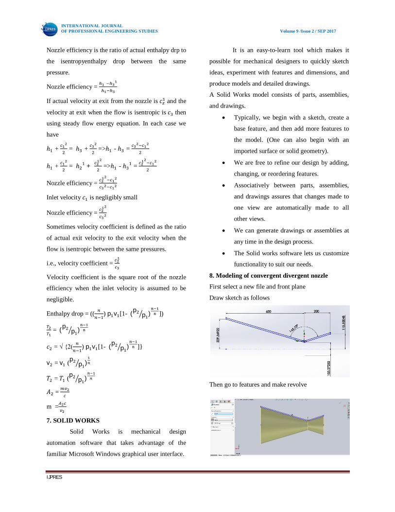
8. Modeling of convergent divergent nozzle
First select a new file and front plane
Draw sketch as follows
Then go to features and make revolve
INTERNATIONAL JOURNAL OF PROFESSIONAL ENGINEERING STUDIES Volume 9 /Issue 2 / SEP 2017
IJPRES
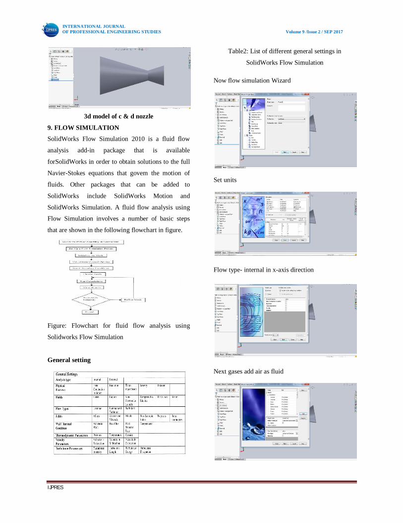
3d model of c & d nozzle
9. FLOW SIMULATION
SolidWorks Flow Simulation 2010 is a fluid flow
analysis add-in package that is available
forSolidWorks in order to obtain solutions to the full
Navier-Stokes equations that govem the motion of
fluids. Other packages that can be added to
SolidWorks include SolidWorks Motion and
SolidWorks Simulation. A fluid flow analysis using
Flow Simulation involves a number of basic steps
that are shown in the following flowchart in figure.
Figure: Flowchart for fluid flow analysis using
Solidworks Flow Simulation
General setting
Table2: List of different general settings in
SolidWorks Flow Simulation
Now flow simulation Wizard
Set units
Flow type- internal in x-axis direction
Next gases add air as fluid
INTERNATIONAL JOURNAL OF PROFESSIONAL ENGINEERING STUDIES Volume 9 /Issue 2 / SEP 2017
IJPRES
Computational domain
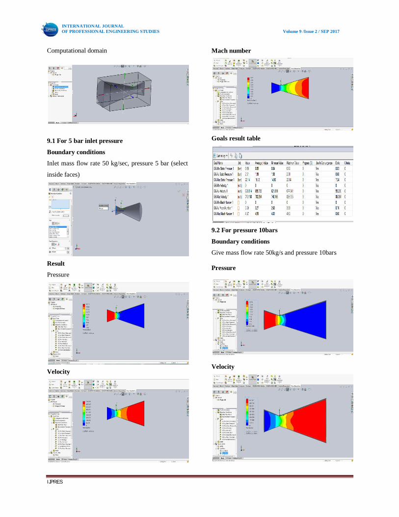
9.1 For 5 bar inlet pressure
Boundary conditions
Inlet mass flow rate 50 kg/sec, pressure 5 bar (select
inside faces)
Result
Pressure
Velocity
Mach number
Goals result table
9.2 For pressure 10bars
Boundary conditions
Give mass flow rate 50kg/s and pressure 10bars
Pressure
Velocity
INTERNATIONAL JOURNAL OF PROFESSIONAL ENGINEERING STUDIES Volume 9 /Issue 2 / SEP 2017
IJPRES
Mach number
Goals tables
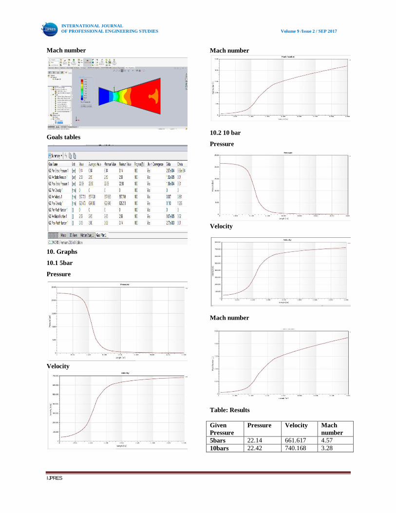
10. Graphs
10.1 5bar
Pressure
Velocity
Mach number
10.2 10 bar
Pressure
Velocity
Mach number
Table: Results
Given Pressure
Pressure Velocity Mach number
5bars 22.14 661.617 4.57 10bars 22.42 740.168 3.28
INTERNATIONAL JOURNAL OF PROFESSIONAL ENGINEERING STUDIES Volume 9 /Issue 2 / SEP 2017
IJPRES
11. Conclusion:
Modeling and analysis of Convergent and
divergent nozzle is done in Solidworks 2016
Modeling of single nozzle is done by using
various commands in solid works and
analyzed at various pressures i.e., at 5bars
and 10bars respectively.
Analysis is done on single nozzle at 5 bars
and 10 bars and values are noted.
Velocity of nozzle at 5 bar and 10 bar
pressure are tabulated in results table.
Thus variations in velocities at certain given
pressures of convergent and divergent
nozzle are analyzed in this project.
12. References:
A.A.Khan and T.R.Shembharkar, “Viscous
flow analysis in a Convergent-Divergent
nozzle”. Proceedings of the international
conferece on Aero Space Science and
Technology, Bangalore, India, June 26-28,
2008.
H.K.Versteeg and W.MalalaSekhara, “An
introduction to Computational fluid
Dynamics”, British Library cataloguing pub,
4th edition, 1996.
David C.Wil Cox, “Turbulence modeling for
CFD” Second Edition 1998.
S.Majumdar and B.N.Rajani, “Grid
generation for Arbitrary 3-D configuration
using a Differential Algebraic Hybrid
Method, CTFD Division, NAL, Bangalore,
April 1995.
Layton, W.Sahin and Volker.J, “A problem
solving approach using Les for a backward
facing-step” 2002.
M.M.Atha vale and H.Q. Yang, “Coupled
field thermal structural simulations in Micro
Valves and Micro channels” CFD Research
Corporation.
Lars Davidson, “An introduction to
turbulence Models”, Department of thermo
and fluid dynamics, Chalmers university of
technology, Goteborg, Sweden, November,
2003.
Kazuhiro Nakahashi, “Navier-Stokes
Computations of two and three dimensional
cascade flow fields”, Vol.5, No.3, May-June
1989.
Adamson, T.C., Jr., and Nicholls., J.A., “On
the structure of jets from Highly
underexpanded Nozzles into Still Air,”
Journal of the Aerospace Sciences, Vol.26,
No.1, Jan 1959, pp. 16-24.
Lewis, C. H., Jr., and Carlson, D. J.,
“Normal Shock Location in underexpanded
Gas and Gas Particle Jets,” AIAA Journal,
Vol 2, No.4, April 1964, pp. 776-777.
Romine, G. L., “Nozzle Flow separation,”
AIAA Journal, Vol. 36, No.9, Sep. 1998. Pp
1618- 1625.
Anderson Jr, J. D., “Computational Fluid
Dynamics the basic with Applications,”
McGrawHill, revised edition 1995.
Dutton, J.C., “Swirling Supersonic Nozzle
Flow,” Journal of Propulsion and Power,
vol.3, July 1987, pp. 342-349.
Elements of Propulsion: Gas Turbines and
Rockets ---- Jack D. Mattingly
Introduction to CFD---- H K VERSTEEG
&W MALALASEKERA