Embed Size (px)
Citation preview

21st Annual CFD Symposium, CFD Division Aeronautical Society of India
08 – 09 August, 2019 Bangalore
Design and CFD Analysis of a Multi Stage Axial Flow Compressor
Lakshya Kumar, Dilipkumar B Alone
Propulsion Division
CSIR-National Aerospace Laboratories, Bangalore, India -560017
Corresponding author: [email protected]
ABSTRACT
Modern day gas-turbine engines are exploited to have better fuel economy, thrust to weight ratio, operational
stability and overall efficiency. Achieving all these parameters is largely dependent on compressor/fan being used
within. Therefore, most of the engine design efforts are drawn into the compressor/fan design. Present study is
intended to build understanding about the design methodology and flow field behavior of multi stage axial flow
compressor. A three stage axial flow compressor, suitable for Small Gas Turbine (SGT) application, has been
designed. The designed compressor stage is intended to deliver mass flow rate of 3.85 kg/s, pressure ratio of
2.36, with stage efficiency of 82% at design speed of 3500 rpm. Steady RANS 3D CFD simulations are carried
out at design and off design speeds to study the interaction among stages and behavior of various flow parameters
at chock point (CP), design point (DP) and numerical stall (NS) conditions. Compressor performance is presented
in terms of compressor maps consisting of pressure ratio (PR) and efficiency variation with respect to mass flow.
Targeted aerodynamic performance is achieved with 1% lower efficiency.
Keywords: Multistage, Axial Flow Compressor, Computational Fluid Dynamics (CFD), Flow Path, Tip Leakage
Vortex (TLV), Spiral Vortex (SV).
INTRODUCTION: The attainment to improve overall efficiency of gas turbine cycle depends on the efficiency of individual
component and synergy among all the component as an engine. However, compression unit of a gas turbine engine
is attributed to be the major player in its efficient performance. Therefore, design of an efficient compression
system calls for huge amount of understanding about the flow physics and its interaction with the other subsequent
components.
Although for the last few decades, CFD techniques are widely being used for the flow analysis in
turbomachinery [1, 2, 3] but some of the spontaneously occurring phenomenon needs more matured CFD
techniques which can accurately predict those. Specifically, flow in the compressors is very complex due to
adverse gradient and its 3D nature over the entire operating range (Choke to stall). Compressor operation near
the stall is highly sensitive to even an incremental change in the pressure [4]. Therefore, for capturing the accurate
stall point, predicting flow behavior at the onset of stall, aerodynamic loading of the blades and sensitiveness of
compressor stability to the design changes, demand more sophisticated CFD techniques as reported by Roger and
Mauro et al [5, 6]. Nevertheless, recent advances in the CFD has incredibly cut down the time and cost involved
in the design of any turbomachinery component by providing holistic prediction of the flow either due to
incremental or large design changes which has been demonstrated by many researchers such as: Howaed et al.
[7] developed streamline curvature through-flow code incorporating 3D flow phenomenon which was validated
with a multistage axial compressor experimental data showing very close match. Leonid et al. [8] demonstrated
an integrated design platform for gas-turbine preliminary design. Major outcome of their approach was significant
reduction in the design cycle time form conceptual design phase to final design including all design and off design
performance. A general capability parametric tool for 3-D design of turbomachinery blade was developed by
Kiren et al. [9]. Where geometric and aerodynamic data is provided as input for airfoil creation which then is
stacked to give 3D blade with minimum CAD interaction. Mark [10] developed a 1-D stage by stage constant
radius compressor performance model which could produce design and off design compressor performance for
commercially available compressors as well as new design with minimum inputs required. Magdy et al [11]

presented another simplified row by row 1-D method for predicting compressor performance under off design
condition using a modified diffusion factor. Sayari et al [12] proposed a new through flow method essentially for
the transonic compressor. The procedure was based on averaging procedure working normal to the cascade
centerline and was found to be in good agreement against the validated data.
With increasing use of multistage compressors, it’s very essential to have idea about the design
methodology, flow physics and interaction of all the stages together under design and off-design conditions. As
a matter of convenience, most of the literature available on compressor studies deals with single stage compressor
however, there are consistent efforts by researchers towards design, analysis and development of multistage
compressor as one unit as reported in [13]. Wherein, Wisler and team under took design and parametric
performance evaluation for a multistage axial compressor. As an outcome, steady revealed the influence of
compressor design parameters on efficiency, operating cost, blade design, fuel consumption and weight of the
engine. John [14] developed a computational model to analyze moderate to long scale flow physics in a high
speed multistage axial compressor. The model was targeted to predict breakdown of the flow physics in the four
stage compressor at different speeds and inlet mass flow. Louis et al [15] pursued aerodynamic design of advanced
multistage axial compressor to achieve high efficiency with high loading, compact size and wide operating range
which was carried out in two phases. First phase was oriented to develop confidence in design methodology
through CFD and inverse design technique, the second phase as an outcome of the first led to development of a
four stage advance axial compressor with stated objectives. In a collaborative research project, Simon and Taylor
et al. [16, 17] introduced 3D blade feature like sweep and dihedral for a multi stage axial compressor rotor and
demonstrated its influence on the flow physics through extensive CFD and experimental analysis. Another
rigorous steady and unsteady CFD analysis were carried out by Christian et al. [18] for a seven stage half scale
compressor. The study was essentially intended to validate their CFD technique in terms of accurately capturing
stall inception and key flow features. Similar work was carried out by Fanzhou et al. [19] to study the post stall
behavior of a multistage compressor. Milan et al. [20] conducted a comparative study between through flow
analysis and traditional CFD for multistage compressor. They concluded that both the methods have pros and
cons, where through flow methods holds good for quick and robust analysis particularly for multistage machines
however, it fails to accurately capture complex flow physics compared to traditional CFD method.
Based on the facts form the literature, it’s evident that lot of parametric studies are required to excel
design challenges and complex flow physics in multistage axial flow compressors. Present study is an effort to
build understanding for designing multistage axial flow compressor using CFD technique to analyses the evolving
flow physics and interaction between each stage from chock to stall conditions over different operating speeds.
General design specifications for the three stage axial compressor are given in the Table 1.
Table 1: General specifications of the three stage axial compressor.
Parameter Value
Rotational Speed (rpm) 35000
Mass flow (kg/s) 3.85
Total Pressure ratio 2.36
Stage-wise PR (π) 1.4, 1.35, 1.25
Isentropic Efficiency (η) 82.00%
Rotor hub tip ratio (rh/rt) R1:0.56, R2:0.65, R3:0.72
No of rotor blades R1:14, R2:19, R3:25
No of stator blades S1:43, S2:55, S3:69
Tip clearance (h) (mm) 0.4
DESIGN METHODOLOGY:
Primary design calculations were carried out using isentropic relations, later the obtained parameters were used
for mean-line design through a commercial 2D design tool. Preliminary flow path is established using inlet total
pressure, temperature, flow angle, total-to-static pressure ratio, mass flow, reference radius, flow and load
coefficients. The compressor flow path is evolved by varying hub and tip end wall which can be seen in the figure
1. Koch & Smith loss model is used for the prediction of performance and stalling conditions of the rotor. Multiple

Circular Arch (MCA) profiles for rotor blades and Double Circular Arc (DCA) profiles for stator blades are used
for all the three stages. 3D blade design is also carried out using commercial tool dedicated for turbomachinery
design. Flow path contour refinement, flow angle adjustment, blade profile corrections and managing the gap
between each stage is done through the same design tool. A 3D model of the compressor stage is depicted in the
figure 2.
Figure 1: Flow path of the compressor stage 2D.
Figure 2: 3D model of the compressor stage.
COMPUTATIONAL METHODOLOGY:
Grid generation: ANSYS Turbogrid has been used for grid generation. O-H topology was chosen for
generating structured hexahedral grid. Spacing between the end-wall and first cell was maintained small enough
to meet y plus (y+) requirement. For assuring the reliability of the solution, grid independent study was carried
out for coarse, medium and fine mesh sizes (1, 1.5 and 2 Million) keeping total pressure ratio as monitoring
parameter. Deviation of the coarse and medium grid was 1.8 % and 0.6 % from the fine grid as can be seen in
figure 3, therefor analysis was continued for the medium grid size. Grid generated for three stages is presented in
the figure 4.
Figure 3: Peak total PR deviation with
respect to grid size.
Figure 4: Computational grid generate for three stage compressor.
Boundary conditions: Single blade row 3D passage for all the three stages was considered for the analysis, as
given in the figure 5. All the solid boundaries were treated as wall with no slip and non-heat transfer. Side walls
of the domain were imposed with periodic boundaries. Inlet of the compressor stage was enforced with total
pressure and total temperature assuming the flow normal to the boundary. Exit boundary of the last stage was
defined with static pressure at mid location having pressure averaging over the entire face
Flow solver: Steady state density based RANS (Reynolds Averaged Navier Stoke) solver including viscous
work was adapted in ANSYS CFX to perform the computational analysis for all the three stages together. SST
(Shear stress transport) k-ω model with 5% turbulence intensity at inlet, was considered for turbulence closure.
Rotor stator interaction plane was defined as mixing plane which does circumferential averaging of the flow
parameter for transferring information at the interface.
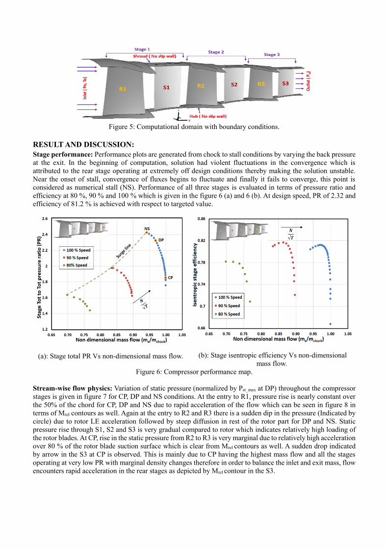
Figure 5: Computational domain with boundary conditions.
RESULT AND DISCUSSION:
Stage performance: Performance plots are generated from chock to stall conditions by varying the back pressure
at the exit. In the beginning of computation, solution had violent fluctuations in the convergence which is
attributed to the rear stage operating at extremely off design conditions thereby making the solution unstable.
Near the onset of stall, convergence of fluxes begins to fluctuate and finally it fails to converge, this point is
considered as numerical stall (NS). Performance of all three stages is evaluated in terms of pressure ratio and
efficiency at 80 %, 90 % and 100 % which is given in the figure 6 (a) and 6 (b). At design speed, PR of 2.32 and
efficiency of 81.2 % is achieved with respect to targeted value.
(a): Stage total PR Vs non-dimensional mass flow.
(b): Stage isentropic efficiency Vs non-dimensional
mass flow.
Figure 6: Compressor performance map.
Stream-wise flow physics: Variation of static pressure (normalized by Pst_max at DP) throughout the compressor
stages is given in figure 7 for CP, DP and NS conditions. At the entry to R1, pressure rise is nearly constant over
the 50% of the chord for CP, DP and NS due to rapid acceleration of the flow which can be seen in figure 8 in
terms of Mrel contours as well. Again at the entry to R2 and R3 there is a sudden dip in the pressure (Indicated by
circle) due to rotor LE acceleration followed by steep diffusion in rest of the rotor part for DP and NS. Static
pressure rise through S1, S2 and S3 is very gradual compared to rotor which indicates relatively high loading of
the rotor blades. At CP, rise in the static pressure from R2 to R3 is very marginal due to relatively high acceleration
over 80 % of the rotor blade suction surface which is clear from Mrel contours as well. A sudden drop indicated
by arrow in the S3 at CP is observed. This is mainly due to CP having the highest mass flow and all the stages
operating at very low PR with marginal density changes therefore in order to balance the inlet and exit mass, flow
encounters rapid acceleration in the rear stages as depicted by Mrel contour in the S3.

Figure 7: Stream-wise static pressure built up at CP, DP and NS for all the three stages.
Figure 8: Tip relative Mach number contours across all the stages at CP, DP and NS.
Span-wise variation of the flow: Figure 9 (a), 9 (b) and 9 (c) show the span-wise variation of the total pressure
(Normalized by S3 exit Po_max at DP) at rotor (R1, R2, R3) and (S1, S2, S3) exit for CP, DP and NS conditions.
As we move along the rear stages, there is increase in the total pressure radially and axially. From the rotor exit
profiles, it can be seen that R1 has huge flow reversal till 60% span for CP and DP which increases at NS almost
till 85 % span with spike in total pressure near the blade tip region. R2 exit profiles have similar distribution over
the entire span for all three conditions with flow reversal up to 75% of span. R3 exit has almost uniform total
pressure distribution for CP except end-wall region however it does have flow reversal over 40% of the span for
DP and NS which is less compared to R1 and R2. S1 and S2 exit profiles are almost same at all the three points
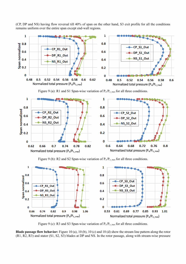
(CP, DP and NS) having flow reversal till 40% of span on the other hand, S3 exit profile for all the conditions
remains uniform over the entire span except end-wall regions.
Normalized total pressure (Po/Po_max)
Normalized total pressure (Po/Po_max)
Figure 9 (a): R1 and S1 Span-wise variation of Po/Po_max for all three conditions.
Normalized total pressure (Po/Po_max)
Normalized total pressure (Po/Po_max)
Figure 9 (b): R2 and S2 Span-wise variation of Po/Po_max for all three conditions.
Normalized total pressure (Po/Po_max)
Normalized total pressure (Po/Po_max)
Figure 9 (c): R3 and S3 Span-wise variation of Po/Po_max for all three conditions.
Blade passage flow behavior: Figure 10 (a), 10 (b), 10 (c) and 10 (d) show the stream line pattern along the rotor
(R1, R2, R3) and stator (S1, S2, S3) blades at DP and NS. In the rotor passage, along with stream-wise pressure
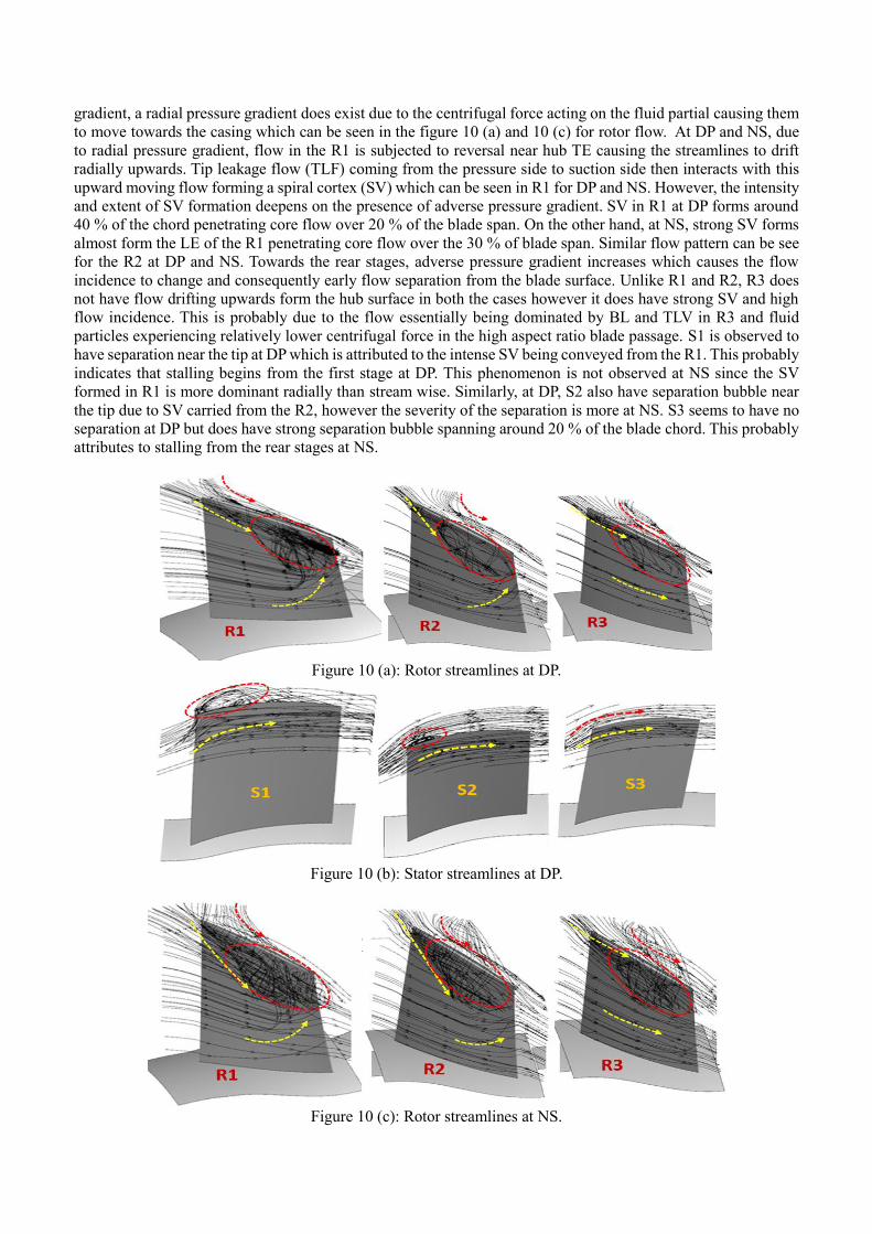
gradient, a radial pressure gradient does exist due to the centrifugal force acting on the fluid partial causing them
to move towards the casing which can be seen in the figure 10 (a) and 10 (c) for rotor flow. At DP and NS, due
to radial pressure gradient, flow in the R1 is subjected to reversal near hub TE causing the streamlines to drift
radially upwards. Tip leakage flow (TLF) coming from the pressure side to suction side then interacts with this
upward moving flow forming a spiral cortex (SV) which can be seen in R1 for DP and NS. However, the intensity
and extent of SV formation deepens on the presence of adverse pressure gradient. SV in R1 at DP forms around
40 % of the chord penetrating core flow over 20 % of the blade span. On the other hand, at NS, strong SV forms
almost form the LE of the R1 penetrating core flow over the 30 % of blade span. Similar flow pattern can be see
for the R2 at DP and NS. Towards the rear stages, adverse pressure gradient increases which causes the flow
incidence to change and consequently early flow separation from the blade surface. Unlike R1 and R2, R3 does
not have flow drifting upwards form the hub surface in both the cases however it does have strong SV and high
flow incidence. This is probably due to the flow essentially being dominated by BL and TLV in R3 and fluid
particles experiencing relatively lower centrifugal force in the high aspect ratio blade passage. S1 is observed to
have separation near the tip at DP which is attributed to the intense SV being conveyed from the R1. This probably
indicates that stalling begins from the first stage at DP. This phenomenon is not observed at NS since the SV
formed in R1 is more dominant radially than stream wise. Similarly, at DP, S2 also have separation bubble near
the tip due to SV carried from the R2, however the severity of the separation is more at NS. S3 seems to have no
separation at DP but does have strong separation bubble spanning around 20 % of the blade chord. This probably
attributes to stalling from the rear stages at NS.
Figure 10 (a): Rotor streamlines at DP.
Figure 10 (b): Stator streamlines at DP.
Figure 10 (c): Rotor streamlines at NS.
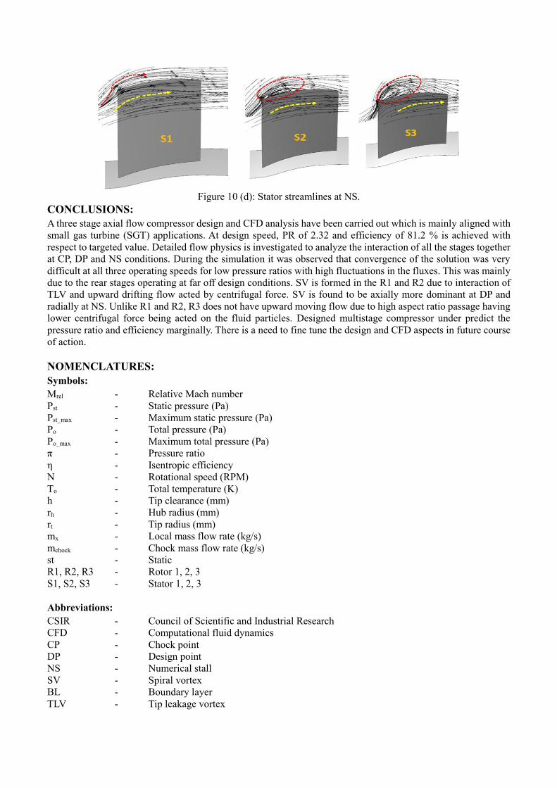
Figure 10 (d): Stator streamlines at NS.
CONCLUSIONS:
A three stage axial flow compressor design and CFD analysis have been carried out which is mainly aligned with
small gas turbine (SGT) applications. At design speed, PR of 2.32 and efficiency of 81.2 % is achieved with
respect to targeted value. Detailed flow physics is investigated to analyze the interaction of all the stages together
at CP, DP and NS conditions. During the simulation it was observed that convergence of the solution was very
difficult at all three operating speeds for low pressure ratios with high fluctuations in the fluxes. This was mainly
due to the rear stages operating at far off design conditions. SV is formed in the R1 and R2 due to interaction of
TLV and upward drifting flow acted by centrifugal force. SV is found to be axially more dominant at DP and
radially at NS. Unlike R1 and R2, R3 does not have upward moving flow due to high aspect ratio passage having
lower centrifugal force being acted on the fluid particles. Designed multistage compressor under predict the
pressure ratio and efficiency marginally. There is a need to fine tune the design and CFD aspects in future course
of action.
NOMENCLATURES:
Symbols:
Mrel - Relative Mach number
Pst - Static pressure (Pa)
Pst_max - Maximum static pressure (Pa)
Po - Total pressure (Pa)
Po_max - Maximum total pressure (Pa)
π - Pressure ratio
η - Isentropic efficiency
N - Rotational speed (RPM)
To - Total temperature (K)
h - Tip clearance (mm)
rh - Hub radius (mm)
rt - Tip radius (mm)
mx - Local mass flow rate (kg/s)
mchock - Chock mass flow rate (kg/s)
st - Static
R1, R2, R3 - Rotor 1, 2, 3
S1, S2, S3 - Stator 1, 2, 3
Abbreviations:
CSIR - Council of Scientific and Industrial Research
CFD - Computational fluid dynamics
CP - Chock point
DP - Design point
NS - Numerical stall
SV - Spiral vortex
BL - Boundary layer
TLV - Tip leakage vortex

TLF - Tip leakage flow
2D, 3D - Two dimensional, three dimensional
SGT - Small gas turbine
PR - Pressure ratio
LE - Leading edge
TE - Trailing edge
MCA - Multiple circular arch
DCA - Double circular arch
REFERENCES:
[1] John J. Adamczyk “Aerodynamic Analysis of Multistage Turbomachinery Flows in Support of Aerodynamic
Design” international Gas Turbine and Aero-engine Congress and Exhibition, Indiana, June 7–10, 1999.
[2] Marble, F. E., 1964, ‘‘Three-Dimensional Flow in Turbomachines, High Speed Aerodynamics and Jet
Propulsion, Aerodynamics of Turbines and Compressors. Princeton University Press.
[3] M. A. Howard and S. J. Gallimore “Viscous Through Flow Modelling for Multi-Stage Compressor Design”
International Gas Turbine and Aero-engine Congress and Exposition Cologne, Germany June 1-4, 1992.
[4] Hone H. “Axial Compressor Stall and Surge Prediction by Measurements” International Journal of Rotating
Machinery 1999, Vol. 5, No. 2, pp. 77-87.
[5] Roger L. Davis and Jixian Yao, “Prediction of Compressor Stage Performance from Choke Through Stall”
Journal of Propulsion and Power Vol. 22, No. 3, May–June 2006.
[6] Mauro Righi, Vassilios Pachidis, Lucas Pawsey “Three-dimensional through-flow modelling of axial flow
compressor rotating stall and surge” Aerospace Science and Technology 78 (2018) 271–279.
[7] M. A. Howard and S. J. Gallimore, “Viscous Through Flow Modelling for Multi-Stage Compressor Design”
International Gas Turbine and Aero-engine Congress and Exposition Cologne, Germany June 1-4, 1992.
[8] Leonid Moroz1, Yuriy Govorushchenko1, Petr Pagur1, Kirill Grebennik1, Wolfgang Kutrieb2, Mike Kutrieb
“Integrated Environment for Gas Turbine Preliminary Design” IGTC-2011-0007.
[9] Kiran Siddappaji, Mark G. Turner and Ali Merchant “General Capability of Parametric 3d Blade Design Tool
for Turbomachinery” Proceedings of ASME Turbo Expo 2012, GT2012, June 11-15, 2012, Copenhagen,
Denmark.
[10] Mark S. Johnson, “One-Dimensional, Stage-By-Stage, Axial Compressor Performance Model”, Presented at
the International Gas Turbine and Aero-engine Congress and Exposition Orlando, FL June 3-6, 1991.
[11] Magdy S. Attia and M. Taher Schobeiri, “A New Method for The Prediction of Compressor Performance
Maps Using One-Dimensional Row-By-Row Analysis”, International Gas Turbine and Aero-engine Congress and
Exposition Houston, Texas - June 5-8, 1995.
[12] N. Sayari, A. B Sics, “A New Through Flow Approach for Transonic Axial Compressor Stage Analysis”,
International Gas Turbine and Aero-engine Congress and Exposition Houston, Texas - June 5-8, 1995.
[13] D.C. Wisler, C.C. Koch, L.H. Smith, Jr, “Preliminary Design Study of Advanced Multi Stage Axial Advanced
Flow Core Compressors” NASA CR 135133, 1996.
[14] John P. Longley” Calculating The Flow Field Behavior of High-Speed Multi-Stage Compressors”
International Gas Turbine & Aero-engine Congress & Exhibition, Orlando, Florida, June 2-June 5,1997.

[15] Louis M. Larosiliere, Jerry R. Wood, Michael D. Hathaway, Adam J. Medd and Thong Q. Dang
“Aerodynamic Design Study of Advanced Multistage Axial Compressor” NASA/TP-2002-211568.
[16] Simon J. Gallimore, John J. Bolger, Nicholas A. Cumpsty, Mark J. Taylor, Peter I. Wright, James M. M.
Place “The Use of Sweep and Dihedral in Multistage Axial Flow Compressor Blading—Part I:
University Research and Methods Development” Journal of Turbomachinery, OCTOBER 2002, Vol. 124/ 521.
[17] Simon J. Gallimore, John J. Bolger, Nicholas A. Cumpsty, Mark J. Taylor, Peter I. Wright, James M. M.
Place “The Use of Sweep and Dihedral in Multistage Axial Flow Compressor Blading Part II: Low and High-
Speed Designs and Test Verification, OCTOBER 2002, Vol. 124/ 541.
[18] Christian Cornelius, Thomas Biesinger, Paul Galpin, Andre Braune “Experimental and Computational
Analysis of a Multistage Axial Compressor Including Stall Prediction by Steady and Transient CFD Methods”
Journal of Turbomachinery JUNE 2014, Vol. 136 / 061013-1.
[19] Fanzhou Zhao, John Dodds and Mehdi Vahdati “Post Stall Behavior of a Multistage High Speed
Compressor at Off-Design Conditions” Journal of Turbomachinery, December 2018, Vol. 140 / 121002-1.
[20] Milan B, Milan P, Alexander W, “Multistage Axial Compressor Flow Field Prediction Using CFD and
Through Flow Calculations” Proceedings of ASME Turbo Expo, GT2016, Seoul, South Korea, June 13-17, 2016.