Embed Size (px)
Citation preview

D(
Va
b
a
ARRAA
KRHQCT
1
sbeSftaharibDflct
0h
Sensors and Actuators A 203 (2013) 62– 68
Contents lists available at ScienceDirect
Sensors and Actuators A: Physical
jo u r n al homep age: www.elsev ier .com/ locate /sna
esign and calibration of a new compact radiative heat-flux gaugeRHFG) for combustion applications
. Mahendra Reddya, S. Sudheerb, S.V. Prabhub, Sudarshan Kumara,∗
Aerospace Engineering Department, Indian Institute of Technology Bombay, Powai, Mumbai 400 076, IndiaMechanical Engineering Department, Indian Institute of Technology Bombay, Powai, Mumbai 400 076, India
r t i c l e i n f o
rticle history:eceived 23 April 2013eceived in revised form 6 August 2013ccepted 6 August 2013vailable online xxx
eywords:adiative heat-flux gaugeigh temperatureuartz plateopper plate
a b s t r a c t
It is important to develop an inexpensive and robust gauge for measuring the contribution of radiationheat-flux component while operating in high temperature conditions without the need of cooling watersupply. This work presents a new compact radiative heat-flux gauge (RHFG) for measuring the radiativeheat-flux from combustion systems operating at high operating temperatures (∼1200 K). Various typesof total heat-flux meters (convective and radiative) are available for measuring heat-flux. In this study,pure radiative heat-flux measuring gauge (RHFG) is developed. Quartz plate is used as a window of RHFGacting as media to transfer pure radiative heat from the heat source. Copper plate is used as the heatsensing element. A thermocouple is brazed to the copper plate to measure the rate of heat transfer tothe sensing element. The mathematical modeling, numerical analysis and construction methodology ofRHFG is discussed. Initially, a large sized gauge (G1) is fabricated and calibrated with cone calorimeter.
hermocouple The measured response time of 670 s is observed for G1. Numerical analysis is carried out to optimize thesize of RHFG and reduce the response time. Four different gauges with various dimensions (G2, G3, G4and G5) are analyzed numerically and a response time of 208, 17, 14 and 12 s respectively is observed.The gauge, G5 is manufactured and calibrated with cone calorimeter with known radiative heat-flux andthe experimental response time of 13 s is observed. This RHFG is of low cost, simple to manufacture,rugged and requires no water cooling even for high temperature combustion applications.
. Introduction
The rate of heat transfer from various heat generating systems,uch as various plumes, fires and inner walls of combustion cham-er in gas turbines and IC engines is an important parameter forfficient design of various safety systems and combustion systems.everal heat-flux gauges which can measure the rate of heat trans-er and work on different principles are developed and reported inhe literature [1–4]. In combustion chambers, pool fires, furnacesnd high temperature sources, combined convective and radiativeeat flues exist. Radiative heat-flux plays a dominant role in over-ll heat transfer. Quantification of mixed heat-flux (convective andadiative) through numerical studies has been extensively reportedn the literature [5–7]. Lam et al. [7] have reported the linear sta-ility analysis and compared the results with three-dimensionalNS studies with modified Rayleigh number to calculate the heat-
ues in mixed environment. Heat transfer from high temperatureombustion products to the cylinder walls in IC (internal combus-ion) engines is one of the most influencing parameters on engine∗ Corresponding author. Tel.: +91 22 2576 7124; fax: +91 22 2572 2602.E-mail addresses: [email protected], [email protected] (S. Kumar).
924-4247/$ – see front matter © 2013 Elsevier B.V. All rights reserved.ttp://dx.doi.org/10.1016/j.sna.2013.08.014
© 2013 Elsevier B.V. All rights reserved.
performance, efficiency (fuel consumption) and exhaust pollutantemissions. Measurement of mixed heat-flux in IC engines is one ofthe most difficult processes [8]. Extensive studies on issues relatedto the measurement of mixed heat-flux in IC engines have beenreported in the literature [8–11]. However, measurement of radia-tive heat-flux in the mixed environment is necessary to quantifyits part from combustion systems. Therefore, some heat-flux sen-sors for these purposes are characterized in radiative environments[12]. Gardon [13] introduced Gardon gauge to measure the inten-sity of thermal radiation in the range of 4.2–4190 kW/m2. Thisgauge consists of a copper cylinder with a thin constantan foil, con-nected to a copper wire, on the top. This copper wire and the coppercylinder form a differential thermocouple with the constantan plate[14]. The working principle of the Gardon gauge is to infer the radi-ation heat-flux by measuring the temperature difference betweenthe center and the edge of a thin metal film [15].
A similar sensor, Schmidt-Boelter gauge [16,17] is developedfor measuring the incident radiative heat-flux. Schmidt-Boeltergauge works on the principle of producing a potential difference
(voltage) due to a temperature difference across a thin thermalresistance layer situated at the sensing surface of the gauge.Both the gauges operate without any external power source andneed water cooling to protect the sensors from high temperature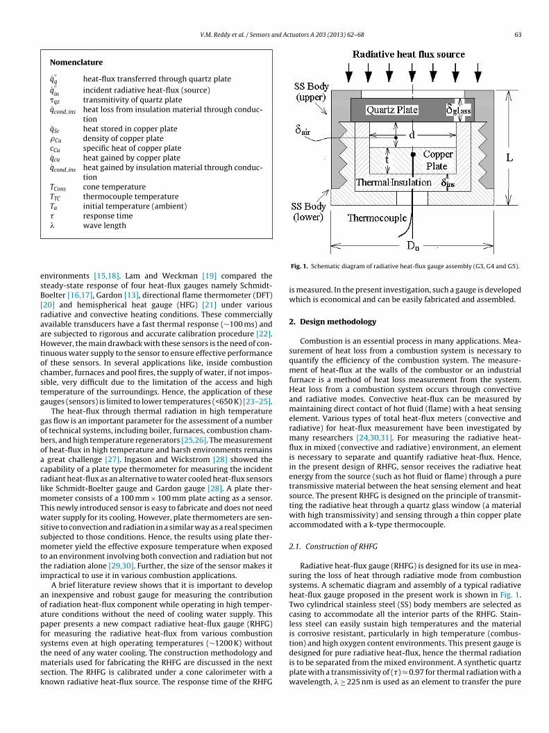
V.M. Reddy et al. / Sensors and Actuators A 203 (2013) 62– 68 63
Nomenclature
q̇′′q heat-flux transferred through quartz plate
q̇′′in
incident radiative heat-flux (source)�qz transmitivity of quartz plateq̇cond,ins heat loss from insulation material through conduc-
tionq̇Sc heat stored in copper plate�Cu density of copper platecCu specific heat of copper plateq̇cu heat gained by copper plateq̇cond,ins heat gained by insulation material through conduc-
tionTCons cone temperatureTTC thermocouple temperatureTa initial temperature (ambient)� response time� wave length
esB[raaHtocstg
goboacrlmTwssmtti
aoapfstmsk
designed for pure radiative heat-flux, hence the thermal radiationis to be separated from the mixed environment. A synthetic quartz
nvironments [15,18]. Lam and Weckman [19] compared theteady-state response of four heat-flux gauges namely Schmidt-oelter [16,17], Gardon [13], directional flame thermometer (DFT)20] and hemispherical heat gauge (HFG) [21] under variousadiative and convective heating conditions. These commerciallyvailable transducers have a fast thermal response (∼100 ms) andre subjected to rigorous and accurate calibration procedure [22].owever, the main drawback with these sensors is the need of con-
inuous water supply to the sensor to ensure effective performancef these sensors. In several applications like, inside combustionhamber, furnaces and pool fires, the supply of water, if not impos-ible, very difficult due to the limitation of the access and highemperature of the surroundings. Hence, the application of theseauges (sensors) is limited to lower temperatures (<650 K) [23–25].
The heat-flux through thermal radiation in high temperatureas flow is an important parameter for the assessment of a numberf technical systems, including boiler, furnaces, combustion cham-ers, and high temperature regenerators [25,26]. The measurementf heat-flux in high temperature and harsh environments remains
great challenge [27]. Ingason and Wickstrom [28] showed theapability of a plate type thermometer for measuring the incidentadiant heat-flux as an alternative to water cooled heat-flux sensorsike Schmidt-Boelter gauge and Gardon gauge [28]. A plate ther-
ometer consists of a 100 mm × 100 mm plate acting as a sensor.his newly introduced sensor is easy to fabricate and does not needater supply for its cooling. However, plate thermometers are sen-
itive to convection and radiation in a similar way as a real specimenubjected to those conditions. Hence, the results using plate ther-ometer yield the effective exposure temperature when exposed
o an environment involving both convection and radiation but nothe radiation alone [29,30]. Further, the size of the sensor makes itmpractical to use it in various combustion applications.
A brief literature review shows that it is important to developn inexpensive and robust gauge for measuring the contributionf radiation heat-flux component while operating in high temper-ture conditions without the need of cooling water supply. Thisaper presents a new compact radiative heat-flux gauge (RHFG)or measuring the radiative heat-flux from various combustionystems even at high operating temperatures (∼1200 K) withouthe need of any water cooling. The construction methodology and
aterials used for fabricating the RHFG are discussed in the next
ection. The RHFG is calibrated under a cone calorimeter with anown radiative heat-flux source. The response time of the RHFGFig. 1. Schematic diagram of radiative heat-flux gauge assembly (G3, G4 and G5).
is measured. In the present investigation, such a gauge is developedwhich is economical and can be easily fabricated and assembled.
2. Design methodology
Combustion is an essential process in many applications. Mea-surement of heat loss from a combustion system is necessary toquantify the efficiency of the combustion system. The measure-ment of heat-flux at the walls of the combustor or an industrialfurnace is a method of heat loss measurement from the system.Heat loss from a combustion system occurs through convectiveand radiative modes. Convective heat-flux can be measured bymaintaining direct contact of hot fluid (flame) with a heat sensingelement. Various types of total heat-flux meters (convective andradiative) for heat-flux measurement have been investigated bymany researchers [24,30,31]. For measuring the radiative heat-flux in mixed (convective and radiative) environment, an elementis necessary to separate and quantify radiative heat-flux. Hence,in the present design of RHFG, sensor receives the radiative heatenergy from the source (such as hot fluid or flame) through a puretransmissive material between the heat sensing element and heatsource. The present RHFG is designed on the principle of transmit-ting the radiative heat through a quartz glass window (a materialwith high transmissivity) and sensing through a thin copper plateaccommodated with a k-type thermocouple.
2.1. Construction of RHFG
Radiative heat-flux gauge (RHFG) is designed for its use in mea-suring the loss of heat through radiative mode from combustionsystems. A schematic diagram and assembly of a typical radiativeheat-flux gauge proposed in the present work is shown in Fig. 1.Two cylindrical stainless steel (SS) body members are selected ascasing to accommodate all the interior parts of the RHFG. Stain-less steel can easily sustain high temperatures and the materialis corrosive resistant, particularly in high temperature (combus-tion) and high oxygen content environments. This present gauge is
plate with a transmissivity of (�) ≈ 0.97 for thermal radiation with awavelength, � ≥ 225 nm is used as an element to transfer the pure

6 nd Actuators A 203 (2013) 62– 68
rmtwpttocwqsipdtpmt
2
ah
q
(
q
irtptp0ahp
q
3
cbtH
TS
4 V.M. Reddy et al. / Sensors a
adiation heat from high temperature source to the sensing ele-ent. For various combustion systems operating in 1000–2400 K
emperature range, the typical thermal radiation is emitted in aavelength range, � ≥ 450 nm. Therefore, a synthetic quartz glasslate is the best option for this purpose. Quartz plate is fixed inhe SS body by tightening the two parts of the body through a finehread provided (shown in Fig. 1) on the body and acts as a windowf the gauge to allow only radiative heat-flux into the RHFG. A thinopper plate with emissivity (ε) 0.74 is used as a sensing elementhich responds with the radiative heat transferred to it through
uartz plate. Direct contact between copper plate and stainlessteel body can further lead to heat loss between the two, resultingn inaccurate estimation of the radiative heat loss. Therefore, silicahenolic is used as an insulation material to minimize the con-uction heat transfer. One face of copper plate is exposed towardhe source through quartz window. On the other face of the cop-er disk, a thermocouple is brazed at the center. Adequate gap isaintained between the copper disk and quartz plate to avoid heat
ransfer through conduction mode from quartz plate.
.2. Working principle
The incident radiative heat from the source falls on the RHFGnd passes through quartz plate and reaches to copper plate. Theeat balance equation for RHFG is described as follows:
˙′′q = �qz × q̇
′′in = q̇
′′cond,ins + q̇
′′Sc (1)
Heat loss through insulation material is neglectedk = 0.42 W/m K).
˙′′q = �qz × q̇
′′in = q̇
′′Sc (2)
Since the heat loss through the air gap and conduction throughnsulation material is negligible, it can be assumed that all the heatadiated by the source and passed through quartz window is con-inuously stored in the copper disk. The Biot number of the copperlate is ∼0.00006. It is calculated by assuming that only one face ofhe copper plate is exposed to radiative heat-flux source (or tem-erature). This value is three orders of magnitude smaller than.1 indicating that the limit of lumped body capacitance model iscceptable in the present approach. Therefore, lumped mass basedeat transfer method is considered for further analysis of the copperlate
˙′′q = �qz × q̇
′′in = �CucCu
dT
dt(3)
. Optimization of the design parameters
In this present study, initially a gauge (G1) is manufactured and
alibrated using a cone calorimeter. Insulation material is providedetween copper plate and SS body. Hence, the radiative heat passedhrough quartz plate is distributed to copper plate and SS body.eat balance equation for G1 is given in Eq. (4). Since the volumeable 1ummary of dimensional parameters of different configurations of RHFG.
Parameter (mm) G1
Length (L) 18
Outer diameter (Do) 15
L/D0 1.2
Copper plate diameter (d) 4
Copper platethickness (t) 4
Air medium length (ıair) 9
Insulation material thickness (ıins) 1.75
Quartz plate thickness (ıglass) 1
Responsetime (s)
Numericalmeasured
615
670
Fig. 2. Details of the computational domain.
of outer body of the gauge is large, a large part of radiative heat istransferred to the body. Therefore, a large response time is requiredto obtain the actual value of the radiative heat-flux.
q̇′′q = �qz × q̇
′′in = q̇Cu + q̇
′′cond,ins + q̇
′′Sc (4)
Numerical analysis is carried out to optimize the design of theRHFG to reduce the response time and size of the gauge. Hence,gauges of different sizes are explored. A brief summary of thedimensions of various gauges used in the present study is givenin Table 1.
3.1. Numerical analysis
Different geometries of gauges (G1, G2, G3, G4 and G5) are con-sidered and numerical studies are carried out to optimize the sizeand reduce the response time of the gauge. A general purpose CFDcode, Fluent 6.3 is used to solve the problem. Two-dimensionalaxisymmetric model is used for simplicity of computation. Thecomputational domain with boundary conditions is shown in Fig. 2.
The RHFG is located 25 mm below the cone. Two-dimensionalNavier–Stokes equations are discretized and then solved in thefinite-volume domain. A number of computations are carried outusing t-grid mesh with a mesh size of 1.5 mm for the cone zoneG2 G3 G4 G5
14 12 10 810 10 8 6
1.4 1.2 1.25 1.334 4 4 34 3 1 14 3 1 11 1 1 11 1 1 1
208 17 14 12– – – 13

nd Actuators A 203 (2013) 62– 68 65
aaIarat[pnfltsasfiea
4
fssemiiprtsiHht
Fig. 3. Calibration of cone calorimeter radiative heat-flux with cone wall tempera-ture.
V.M. Reddy et al. / Sensors a
nd 0.2 mm for RHFG. The mesh is refined after every simulationnd the results presented in this paper are independent of the grid.nterfaces of different materials are coupled. Pressure outlet bound-ry condition is considered at boundary edges of the domain. Aadiative heat source condition is given on the cone coil surfacend considered as wall and the temperature of the wall is main-ained constant at 973 K (38.09 kW/m2). Roseland radiation model32] is used in this study. The temperature variation at the centeroint of the copper plate is plotted with respect to time. Althougho flow is involved in the present studies; however a very smallow is created due to buoyancy. Bouyant flow is generated dueo temperature gradients between the geometry surface and outerurface. Therefore, laminar flow viscous model is considered withir as the working fluid. Boussinesq density approximation is con-idered for buoyancy condition. Specific heats were defined as aunction of the temperature (piecewise polynomial). The solutions considered to be converged when RMS residuals of the flow andnergy equations are of the order of 10−6 and 10−9, respectively,nd there are no appreciable changes in the respective residuals.
. Calibration of RHFG with cone calorimeter
Heat-flux measurement is a complex process that requires care-ul design and implementation of both sensors and calibrationystems to ensure accuracy in the measurements [19,24,33]. Sen-or calibration techniques attempt to mimic the measurementnvironment as closely as possible with high repeatability. Pri-ary calibration procedure for newly designed or fabricated RHFG
nstrument is one in which the radiative heat-flux is character-zed according to established temperature standards [34,35]. Theresent RHFG is calibrated under cone calorimeter with knownadiative heat-flux. Cone calorimeter (FTT make) is used as the con-rolled heat-flux source. It consists of the heating coil at the top, aample holder and a load cell. The calibration of the heating coil
s carried out with the help of a heat-flux sensor (Schmidt-Boeltereat-Flux Sensor) at a distance of 60 mm from the bottom of theeating coil. The variation of the radiative heat-flux with tempera-ure of cone calorimeter is shown in Fig. 3 (given by the supplier).Fig. 4. Calibration of RHFG u
RHFG is vertically positioned in cone calorimeter and calibratedfor different radiative heat-flux levels. The schematic diagram isshown in Fig. 4. The face of the RHFG (quartz window) is arrangedin upper side to expose the sensor to the radiative heat-flux fromthe cone. The photographic image of orientation and calibration ofRHFG under cone calorimeter is shown in Fig. 5. The output voltageof thermocouple is collected by a data acquisition system. Thermo-couple temperature variation data with time is collected at everytime interval of 50 ms. After each run of calibration with knownradiative heat-flux, the RHFG is removed from the cone calorime-
ter and allowed to cool till the room temperature. The calibrationnder cone calorimeter.

66 V.M. Reddy et al. / Sensors and Actuators A 203 (2013) 62– 68
sc
5
iltcaGTafnRgt2rtsqctbi
Fig. 5. Photograph of RHFG calibration under cone calorimeter.
heet of present RHFG is shown in Fig. 8. Response time of RHFG isalculated from first order system equation [36].
TCone − TTC
TCone − Tee−t/� (5)
. Numerical and experimental results
The experimentally measured response time of the gauge (G1)s 670 s. The response time obtained from detailed numerical simu-ations of this gauge is 615 s. Experimental and numerical responseimes of G1 are close to each other. Therefore, the given numericalonditions are considered as suitable for optimization of RHFG sizend to minimize the response time. Four different gauges (G2, G3,4 and G5) are considered with different component dimensions.he quartz plate thickness of 2 and 1 mm are used on RHFG (G1)nd experimentally measured. Same response time is observedor both the cases. To reduce the size of the RHFG, 1 mm thick-ess quartz plate is used for numerical analysis of different sizedHFGs of G2, G3, G4 and G5. The volume of SS body material for G2auge is reduced by 70% as compared with G1. Hence, the responseime obtained from numerical analysis was reduced from 615 s to08 s. Similarly, for G3, G4 and G5 gauges, the insulation mate-ial is extended till the quartz plate to avoid the heat loss fromhe transmitted heat through radiation to stainless steel body, ashown in Fig. 1. The heat transmitted from source to sensor throughuartz plate directly reaches the copper plate. The thickness of the
opper plate greatly influences the RHFG response time. Responseime decreases with a decrease in the thickness of the copper plateecause of the thermal inertia due to conduction. The thermocouples located at the center of copper plate. A very thin thermocouple of
Fig. 6. Numerical and experimenta
Fig. 7. Temperature distribution contours at 23 s for RHFG (G5).
size 0.5 mm diameter is used to ensure that the response of the ther-mocouple (0.3 s) is very small as compared to RHFG. The computedresponse time for G3, G4 and G5 gauges is 17, 14 and 12 s respec-tively. Numerical and experimental results for all the gauges areshown in Fig. 6. Based on the numerical analysis, G5 gauge has beenconsidered as minimum possible small size which can be easilyfabricated. Hence, G5 is fabricated and calibrated under a standardcone calorimeter. The dimensional details of the gauge G5 are givenin Table 1. A response time of � = 12 s is observed from the repetitivecalibration of the gauge in the cone calorimeter. The temperaturedistribution in the computational domain with RHFG (G5) at 23 sof a computational time is shown in Fig. 7. The overall dimensionsof RHFG are 8 mm diameter (D) and 6 mm length (L) of the gauge.The calibration chart for G5 gauge at different radiative heat-fluxesis shown in Fig. 8. The data obtained from the calibration of theradiative heat-flux gauge with a known source follows a polyno-mial regression equation given as q̇
′′in
= 0.015V2 + 1.974V − 0.23.However, the value of the coefficient of the second order term isvery small (contribution of second term less than 0.1% in the oper-ating range) and hence, a linear variation of the regression equationis considered. The variation of linear regression is represented bya solid line in Eq. (6). The present RHFG (G5) is robust enough towithstand high temperature environment. Since number of com-
ponents and cost of fabrication is relatively very small, this RHFGcan be easily fabricated. The calibrated radiative heat-flux variationl response time for all RHFGs.

V.M. Reddy et al. / Sensors and Ac
ff
q
6
dbwsdtt(sitoids1frcm
R
[
[
[
[
[
[
[[
[
[
[
[
[
[
[
[
[
[
[
[
[
[
[[
[
[
[
Fig. 8. Calibration sheet for RHFG (G5).
or G5 is followed the linear regression with trend line equation asollows:
˙′′in = 2.419V − 1.796 (6)
. Conclusions
In the present work, radiative heat-flux gauge (RHFG) isesigned and calibrated for measuring radiative heat-flux for com-ustion applications at high flame temperature (around 1200 K)ithout water cooling. This RHFG is designed at economic cost,
imple for fabrication and rugged. Quartz plate is used as a win-ow of RHFG acting as media to transfer pure radiative heat fromhe heat source. Copper plate is used as heat sensing element. Ahermocouple is brazed to copper plate. Initially a large size gaugeG1) is fabricated and calibrated with cone calorimeter. The mea-ured response time of 670 s is observed for G1. Numerical analysiss carried out to optimize the size of RHFG and reduce the responseime. The numerically predicted response time of G1 is 615 s. It isbserved that the numerical results are matching well with exper-mental results for the case of G1. Four different RHFG with variousimensions (G2, G3, G4 and G5) are analyzed numerically with theame numerical parameters. The response time of 208, 17, 14 and2 s are observed for G2, G3, G4 and G5 respectively. It is observedrom this study, the decreased size of sensing element reduces theesponse time of the RHFG. The G5 is fabricated and calibrated withone calorimeter with known radiative heat-flux and the experi-ental response time of 13 s is observed.
eferences
[1] A.V. Mityakov, S.Z. Sapozhnikov, V.Y. Mityakov, A.A. Snarskii, M.I. Zhenirovsky,J.J. Pyrhönen, Gradient heat flux sensors for high temperature environments,Sens. Actuators A: Phys. 176 (2012) 1–9.
[2] J.G. Poloniecki, A. Vianou, E. Mathioulakis, Steady-state analysis of the zero-balance heat-flux meter, Sens. Actuators A: Phys. 49 (1995) 29–35.
[3] R.A. Koestoer, Zero method heat flux sensor, Sens. Actuators A: Phys. 7 (1985)145–151.
[4] L.W. Langleya, A. Barnesa, G. Matijasevic, P. Gandhi, High-sensitivity, surface-attached heat flux sensors, Microelectron. J. 30 (1999) 1163–1168.
[5] R.M. Goody, The influence of radiative transfer on cellular convection, J. FluidMech. 1 (1956) 424–435.
[6] C.H. Lan, O.A. Ezekoye, J.R. Howell, K.S. Ball, Stability analysis for three-dimensional Rayleigh–Bénard convection with radiatively participatingmedium using spectral methods, Int. J. Heat Mass Trans. 46 (2003) 1371–1383.
tuators A 203 (2013) 62– 68 67
[7] C.L. Hackert, J.L. Ellzey, O.A. Ezekoye, Combustion and heat transfer in modeltwo-dimensional porous burners, Combust. Flame 116 (1999) 177–191.
[8] J.M. Desantes, A.J. Torregrosa, A. Broatch, P. Olmeda, Experiments on the influ-ence of intake conditions on local instantaneous heat flux in reciprocatinginternal combustion engines, Energy 36 (2011) 60–69.
[9] A.J. Torregrosa, V. Bermúdez, P. Olmeda, O. Fygueroa, Experimental assess-ment for instantaneous temperature and heat flux measurements under dieselmotored engine conditions, Energy Convers. Manage. 54 (2012) 57–66.
10] C.D. Rakopoulos, G.C. Mavropoulos, Experimental instantaneous heat fluxes inthe cylinder head and exhaust manifold of an air-cooled diesel engine, EnergyConvers. Manage. 41 (2000) 1265–1281.
11] J. Serras-Pereira, P.G. Aleiferis, D. Richardson, Imaging and heat flux mea-surements of wall impinging sprays of hydrocarbons and alcohols in adirect-injection spark-ignition engine, Fuel 91 (2012) 264–297.
12] W.M. Pitts, A.V. Murthy, J.L. de Ris, J.R. Filtz, K. Nygàrd, D. Smith, I. Wetterlund,Round robin study of total heat flux gauge calibration at fire laboratories, FireSaf. J. 41 (2006) 459–475.
13] R. Gardon, An instrument for the direct measurement of intense thermal radi-ation, Rev. Sci. Instrum. 24 (1953) 366–370.
14] C.H. Kuo, A.K. Kulkarni, Analysis of heat flux measurement by circular foil gagesin a mixed convection/radiation environment, J. Heat Transfer. 113 (1991)1037–1040.
15] P.S. Cumber, Measuring radiation heat fluxes from a jet fire using a lumpedcapacitance model, Fire Technol. 47 (2011) 665–685.
16] E. Schimidt, Device for the measurement of heat, March 3, 1925, US 1,528,383.17] L.M.E. Boelter, Thermoelectric heat flow response device, January 3, 1950, US
2,493,651.18] C.T. Kidd, C.G. Nelson, How the Schmidt-Boelter gage really works, in:
Proceedings of the 41st international instrumentation symposium, ISA, Aurora,CO, September, 1975, pp. 347–388.
19] C.S. Lam, E.J. Weckman, Steady-state heat flux measurements in radiative andmixed radiative-convective environments, Fire Mater. 33 (2009) 303–321.
20] N.R. Keltner, Directional flame thermometers—a tool for measuring thermalexposure in furnaces and improving control, in: Interflam 2007 ConferenceProceedings (CD version), Interscience Communications, London, UK, 2007.
21] T.K. Blanchat, L.L. Humphries, W. Gill, Sandia heat flux gauge thermal responseand uncertainty models. Thermal Measurements: The Foundation of Fire Stan-dards. ASTM Special Technical Publication 1427, American Society for Testingand Materials, West Conshohocken, PA, 2002, pp. 81–110.
22] X. Silvani, F. Morandini, Fire spread experiments in the field: temperature andheat fluxes measurements, Fire Saf. J. 44 (2009) 279–285.
23] A.R. Gifford, D.O. Hubble, C.A. Pullins, T.E. Diller, S.T. Huxtable, A durable heatflux sensor for extreme temperature and heat flux environments, J. Thermo-phys. Heat Transfer. 24 (2010) 69–76.
24] C.A. Pullins, High temperature heat flux measurement: sensor design, calibra-tion, and applications, Virginia Polytechnic Institute and State University, 2011(Ph.D thesis).
25] N. Martins, M.G. Carvalho, N. Afgan, A.I. Leontiev, A radiation and convectionflux meter for high temperature applications, Exp. Therm. Fluid Sci. 22 (2000)165–173.
26] N. Martins, M.G. Carvalho, N. Afgan, A.I. Leontiev, A new instrument for radi-ation heat flux measurement-analysis and parameter selection, Heat Recov.Syst. CHP. 15 (1995) 787–796.
27] D. Seo, S. Jung, S.J. Lombardo, Z.C. Feng, J.K. Chen, Y. Zhang, Fabrication andelectrical properties of polymer derived ceramic (PDC) thin films for high tem-perature heat flux sensors, Sens. Actuators A: Phys. 165 (2011) 250–255.
28] H. Ingason, U. Wickstrom, Measuring incident radiant heat flux using the platethermometer, Fire Saf. J. 42 (2007) 161–166.
29] A. Bystrom, U. Wickstrom, M. Veljkovic, Use of plate thermometers for betterestimate of fire development, Appl. Mech. Mater. 82 (2011) 362–367.
30] U. Wickstrom, A. Robbins, G. Baker, The use of adiabatic surface temperatureto design structures for fire exposure, J. Struct. Fire Eng. 2 (2011) 21–28.
31] R. Bryant, C. Womeldorf, E. Johnsson, T. Ohlemiller, Radiative heat flux mea-surement uncertainty, Fire Mater. 27 (2003) 209–222.
32] Radiation Modelling: Rosseland Model, ANSYS CFX-Solver, Release 10.0.33] C.A. Pullins, T.E. Diller, In situ high temperature heat flux sensor calibration,
Int. J. Heat Mass Transfer. 53 (2010) 3429–3438.34] A.V. Murthy, Transfer calibration of heat flux sensorat NIST, HTD, vol. 345, in:
National Heat Transfer Conference ASME, 1997.35] A.V. Murthy, B.K. Tsai, R.D. Saunders, High heat flux sensor calibration using
black body radiation, Metrologia 35 (1998) 501–504.36] P.R.N. Childs, J.R. Greenwood, C.A. Long, Heat flux measurement techniques,
Proc. Inst. Mech. Eng. C 213 (1999) 655–677.
Biographies
V. Mahendra Reddy recently completed his Ph.D. in the Department of AerospaceEngineering at Indian Institute of Technology Bombay, Mumbai, India. He graduated
with Master of Technology (Mech. Engg.) from Indian Institute of Technology Kan-pur, India in 2008, a Bachelor of Technology from J.N.T.U. College of engineering,Kakinada in 2005. His research interests are Flameless combustion, Emissions con-trol, Liquid fuel Spray analysis, Turbulent combustion with high swirl flows, heattransfer studies and heat flux measurement.
6 nd Ac
SIlpopmEe
SIfin
8 V.M. Reddy et al. / Sensors a
. Sudheer completed his Ph.D. in the Department of Mechanical Engineering atndian Institute of Technology, Bombay, India. His work addresses some key chal-enges in fire research such as the various factors that influence the radiativeroperties of pool fires. Adiabatic surface temperature has been applied inside thepen pool fires for thermal tests, thus reduces the numerical computation to sim-le conduction problem. His M.Tech thesis (at NIT, Rourkela, India) comprises ofinimizing the internal sloshing motion in fuel tanks using CFD package, FLU-
NT. He introduced a new parameter percentage reduction which enables to verifyffectiveness of different baffles.
.V. Prabhu is professor at the Department of Mechanical Engineering, Indiannstitute of Technology, Bombay, India. He graduated with a B.E. (Mech. Engg.)rst class with distinction from Mysore University in 1988, a Master of Tech-ology from National Institute of Technology, Surathkal in 1991 and a PhD
tuators A 203 (2013) 62– 68
from Indian Institute of Technology, Bombay in 1998. His research interestsare flowmetering, heat transfer studies involving jet impingement, fire dynam-ics, renewable energy (hydrokinetic turbines and wind turbines), gas turbineblade cooling, two phase flow and melting and solidification of PCM andmetals.
Sudarshan Kumar is currently working as an associate professor in the Depart-ment of Aerospace Engineering, Indian Institute of Technology, Bombay, India. Hegraduated with a B.E. (Mech. Engg.) first class with distinction from Aurangabad Uni-
versity in 1998, a Master of Engineering from Indian Institute of Science Bangalorein 2000 and a Ph.D. from Indian Institute of Science Bangalore in 2004. His researchinterests are in the field of combustion, flame dynamics, heat transfer studies in com-bustion systems, flameless/mild combustion, micro combustion and combustioninstabilities.


![TFAWS Interdisciplinary Paper Session · Radiometer Heat flux gauge ... [F] Time [seconds] iCQ02n01 iCQ09p00 iCQ11n00 iCQ14n00 iCQ17n01 iCQ21p01 iCQ21p00 iCQ21n00 iCQ21n01 iCQ24p00](https://img.pdfslide.us/doc/110x75/5e607b0c63c81137db3459e8/tfaws-interdisciplinary-paper-session-radiometer-heat-flux-gauge-f-time-seconds.jpg)