Embed Size (px)
Citation preview
International Conference on Industrial Engineering and Systems Management
IESM 2007
May 30 - June 2, 2007
BEIJING - CHINA
Design and Application of Reconfigurable Manufacturing Systems in Agile Mass Customization
Manufacturing Environment*
Bo Xing a , WenJing Gaob, Dr. Nkgatho S. Tlalea, Prof. Glen Brightc
a Counsil of Scientific and Industrial Research (CSIR),
Material Science & Technology (MST), 0001 Pretoria, South Africa b Wirtschaftswissenschaften, Universität Kassel, 34109 Kassel, Germany
c School of Mechanical Engineering, University of KwaZulu-Natal, 4001 Durban, South Africa
Abstract Manufacturing companies are faced with the challenge of unpredictable, high frequency market changes in both local and international markets. There is a need for greater, more effective responsiveness by manufacturers to change their manufacturing processes. Many manufacturing techniques are based on the principles of Flexible Manufacturing and Dedicated Manufacturing for mass production. Reconfigurable Manufacturing System, (RMS), is a manufacturing system that can provide for Agile Manufacturing, (AM). This has lead to research on the concept, design and equipment implementation for RMS. RMS requires three key capabilities: rapid changeover between products, rapid introduction to new products and unattended operation. The relationship between these manufacturing techniques has been investigated. Research has been focused on the design of Reconfigurable Modular Machine, (RMM), for RMS. The research has addressed the design of subsystems for RMM by using the generic modular mechatronic control. This approach includes modular machine controller hardware, software, mechanical design and generic “plug-and-play” capability. These design of subsystems allowed for rapid reconfiguration of RMS that increased system efficiency and significantly minimized manufacturing change over downtime. Key words: RMS, MCM, Modular Mechatronic Control
1 Introduction
Manufacturing companies of today are faced with the challenge of unpredictable, high frequency market changes in both local and international markets. There is a need for greater, more effective responsiveness by manufacturers to change their manufacturing processes to Mass Customization Manufacturing, (MCM). There are some manufacturing techniques used that are based on the principles of Flexible Manufacturing and Dedicated Manufacturing production [3]. To fulfil these purposes, the concept of Reconfigurable Manufacturing System, (RMS), was introduced and it has three key capabilities: rapid changeover between products, rapid
* This paper was not presented at any other revue. Corresponding author Bo Xing. Tel. +27-12-8413053. Fax +27-12-8414209 Email addresses: [email protected] (Bo Xing)

IESM 2007, BEIJING – CHINA, May 30 - June 2 introduction to new products and unattended operation. The relationship between these manufacturing techniques is illustrated in Figure1. RMS falls within the scope of Agile Manufacturing, (AM). AM requires the use of technologies that can be used to manufacture and check product quality within a variety of family products without extensive retooling.
Research has been focused on the design of: modular machine for reconfigurable machining system which is one of subsystems and was integrated into a Computer Integrated Manufacturing (CIM) cell. The research addressed the design of subsystem of Reconfigurable Manufacturing System, (RMS), by using the generic modular mechatronic control approach. This approach includes modular machine controller hardware, software, mechanical design and generic “plug-and-play” capability. These designs of subsystem allowed for rapid reconfiguration of reconfigurable machining system that increased system efficiency and significantly minimized manufacturing downtime.
Fig. 1. The comparison of three kinds of manufacturing systems [9].
The objective of this research project (as illustrate in Figure 1) were to develop some kinds of automated machines. One is Reconfigurable Modular Machine, (RMM), design for reconfigurable machining system that was able to Mass Customization Manufacturing, (MCM). A reconfigurable machining system design was focused on three key characteristics: decomposition, standardization and exchangeability. This subsystem was controlled by a generic modular mechatronic control system design, the control system allowed for the operation of different subsystems within RMS.
Fig. 2. Diagrammatic Representation of Agile Mass Customization Manufacturing Environment
Figure 1 describes the four integral components (① , ② , ③and④ ) leading to the implementation of
reconfigurable manufacturing, as well as outlining the core principals of Agile MCM environment. The market/customer requirements are those of custom made products manufactured in a mass production
IESM 2007, BEIJING – CHINA, May 30 - June 2 environment. The finished product should be competitive, (low cost), and have exceptional quality standards. Different automated machines can be reconfigurable to do multiple tasks for production of various assemblies. These automated machines consist of different subsystems which are the key components of the RMS.
The generic modular mechatronic control system included motion and communication design and implementation. This allowed the subsystems can be controlled automatically via PC level programming. A generic “plug-and-play” system should provide the facility for control to be interchangeable with various automated machines. This produced uniformity amongst the machines and reduced the downtime in cases of malfunction.
2 RMM design for RMS
To realize this concept of Reconfigurable Manufacturing System RMM must fulfil various functions through the combination of distinct building blocks, modules, etc. Various modular machines have been proposed as models and built up machines. These are illustrated in Figure 3.
(a)Two axis configuration (b) Three axis configuration (c) Initial configuration (d) After reconfiguration
Fig. 3. Few configurations of the prototype modular machines [13].
The purpose of the design of the reconfigurable machining system was to provide the capacity and functionality for the machining operation. The core engineering method needed for machine-level design was that of a systematic design of modular machines. [5] The design of the machine utilized a library of machine modules which provided a platform for fundamental motion analysis. A set of RMMs could be connected together to generate the new type of machining system: reconfigurable machining system.
There were three key aspects for the design of the modular machine: manufacturing requirements, control requirements and mechanical requirements.
2.1 Manufacturing Requirements
� Dedicated Manufacturing System, (DMS): Designed for narrowly defined production requirements
(normally one part at large volume) that are supposed to remain constant over the lifetime of the machining system. This system is custom-designed to machine a specific set of features at a constant cycle time. It would not cost-effectively accommodate the rapidly changes in production requirements.
� Flexible Manufacturing System, (FMS): Designed for loosely defined production requirements that are supposed to significantly change in an unknown manner over time. FMS often has the excessive capacity to fulfil the undefined production requirements which causes the customer to pay for unneeded capabilities.
� Reconfigurable Manufacturing System, (RMS): Designed for MCM requirements, it cost-effectively combines the attractive feature of DMS and FMS: robust performance and the ability to accommodate new production requirements. The RMS is structured by a series of modular machines which can be changed of the machining operations during a short time and at a low cost so that the whole RMS can meet the rapidly changing market requirements. [12]
2.2 Manufacturing Requirements
IESM 2007, BEIJING – CHINA, May 30 - June 2 � CNC controllers: Typical CNC controllers posses comprehensive architectures (hardware and
software) to provide processing flexibility; however not all of the built-in functionality may be used. Furthermore these components cannot be cost-effectively upgraded because of the unnecessary costs are incurred due to software development, installation and maintenance.
� RMM Controllers: Design based on the concept of open-architecture. In open-architecture control, both software components and hardware components are modular. This generic modular mechatronic controller for modular machine allows the machine can be reconfigured when market/customer requirements change or new technology becomes available [5].
2.3 Mechanical Requirements
Designed for a machine to meet the productivity and quality demands of an operation, it must fulfil a variety of requirements including the ability to produce the specified motions and satisfy the part tolerance specifications. There are two key aspects during the mechanical-level design of modular machine: Kinematic Viability and Structural Stiffness [7]. Good kinematic viability makes the machine perform the various motions required to produce the needed features. Reliable structural stiffness of machine can decrease the possibility of geometric errors.
Examples of part family from the market/customer requirements are as in Figure 4:
Fig. 4. Part family : two kinds of engine blocks. A CAD/CAM software package (Unigraphics) was used to produce a module library. According to the different market/customer requirements, different prototypes of modular machines were designed and analysed in the virtual computer environment. It is showed in Figure 5.
Fig. 5. MR2G modular machine conceptual design.
According to the conceptual design, MR2G research group built a real modular machine with modular mechatronic control system. The RMM is assembled from a module library in the computer environment and its modular structure (in both hardware and software) allows is to be converted in a cost-effective method when the market/customer requirements change. RMM has four principal motion systems: Automatic Part Transfer System (APTS), Automatic Part Clamping and Rotating System (APC/RS), Automatic Part Lifting System (APLS), and Automatic Tool Changing System (ATCS). The integration of four motion systems enables the RMM to machine the similar part from the part-family without extensively changing the machine structure.The following figures show the different components of MR2G RMM.
IESM 2007, BEIJING – CHINA, May 30 - June 2
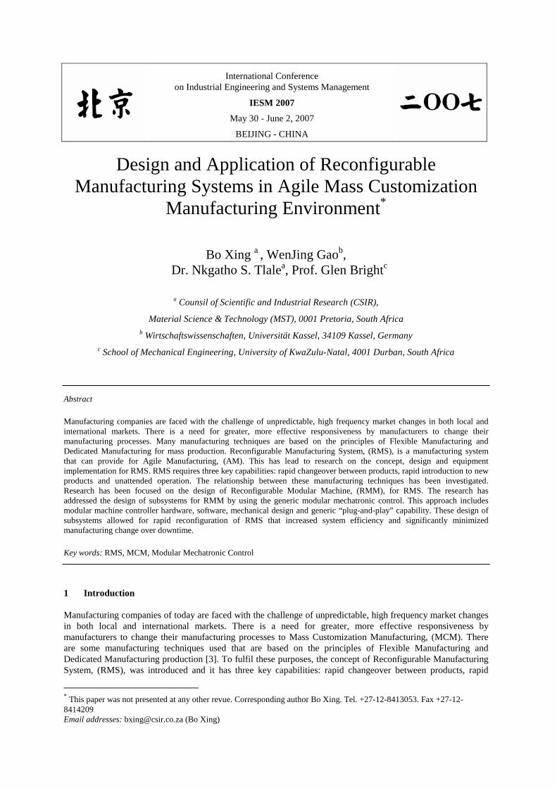
Fig. 6. Part transfer components for RMM.
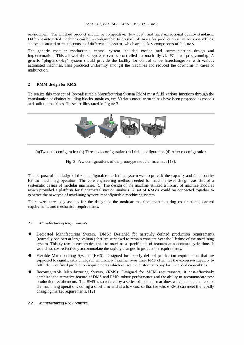
Fig. 7. Lifting table and clamping component for RMM.
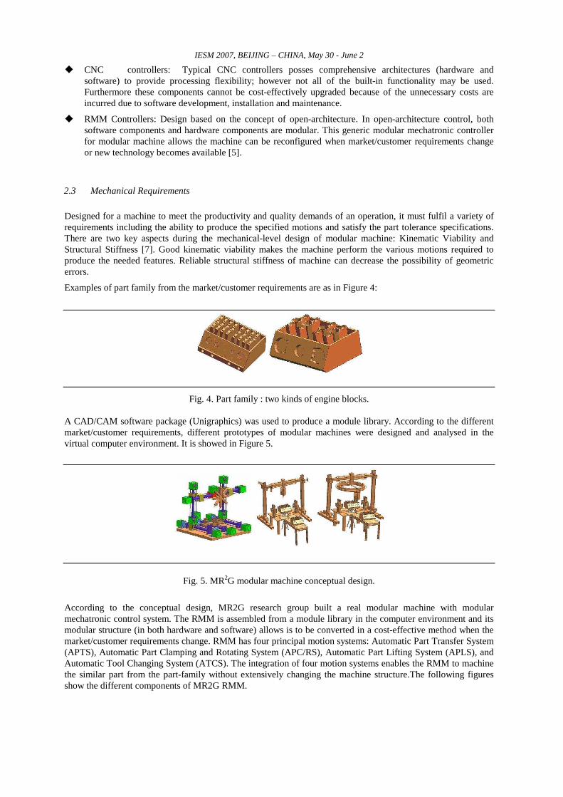
Fig. 8. Auto-tool changing component for RMM.
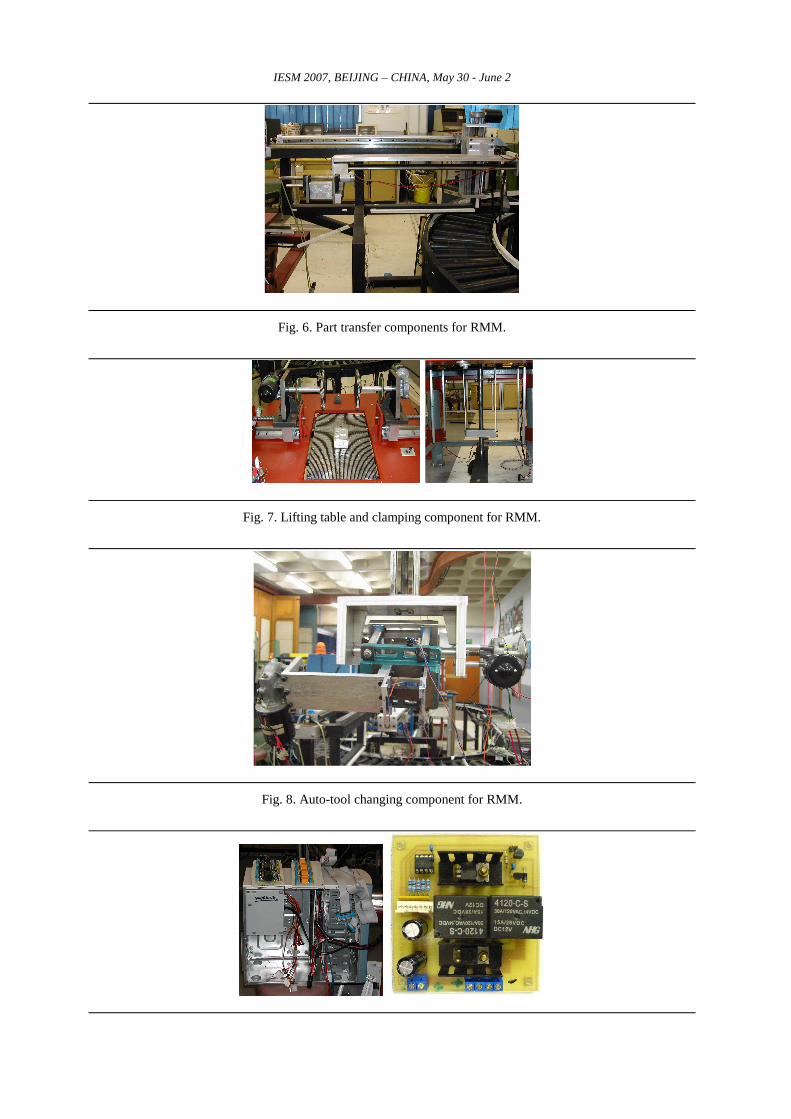
IESM 2007, BEIJING – CHINA, May 30 - June 2 Fig. 9. Modular mechatronic controller card and case for RMM
3 RMS for Mass Customization Manufacturing
3.1 Mass Customization Manufacturing (MCM)
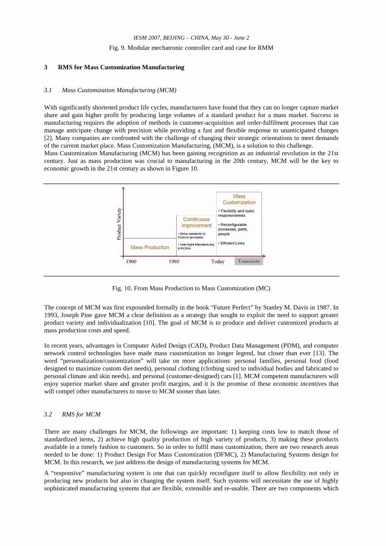
With significantly shortened product life cycles, manufacturers have found that they can no longer capture market share and gain higher profit by producing large volumes of a standard product for a mass market. Success in manufacturing requires the adoption of methods in customer-acquisition and order-fulfilment processes that can manage anticipate change with precision while providing a fast and flexible response to unanticipated changes [2]. Many companies are confronted with the challenge of changing their strategic orientations to meet demands of the current market place. Mass Customization Manufacturing, (MCM), is a solution to this challenge. Mass Customization Manufacturing (MCM) has been gaining recognition as an industrial revolution in the 21st century. Just as mass production was crucial to manufacturing in the 20th century, MCM will be the key to economic growth in the 21st century as shown in Figure 10.
Fig. 10. From Mass Production to Mass Customization (MC)
The concept of MCM was first expounded formally in the book “Future Perfect” by Stanley M. Davis in 1987. In 1993, Joseph Pine gave MCM a clear definition as a strategy that sought to exploit the need to support greater product variety and individualization [10]. The goal of MCM is to produce and deliver customized products at mass production costs and speed. In recent years, advantages in Computer Aided Design (CAD), Product Data Management (PDM), and computer network control technologies have made mass customization no longer legend, but closer than ever [13]. The word “personalization/customization” will take on more applications: personal families, personal food (food designed to maximize custom diet needs), personal clothing (clothing sized to individual bodies and fabricated to personal climate and skin needs), and personal (customer-designed) cars [1]. MCM competent manufacturers will enjoy superior market share and greater profit margins, and it is the promise of these economic incentives that will compel other manufacturers to move to MCM sooner than later.
3.2 RMS for MCM
There are many challenges for MCM, the followings are important: 1) keeping costs low to match those of standardized items, 2) achieve high quality production of high variety of products, 3) making these products available in a timely fashion to customers. So in order to fulfil mass customization, there are two research areas needed to be done: 1) Product Design For Mass Customization (DFMC), 2) Manufacturing Systems design for MCM. In this research, we just address the design of manufacturing systems for MCM.
A “responsive” manufacturing system is one that can quickly reconfigure itself to allow flexibility not only in producing new products but also in changing the system itself. Such systems will necessitate the use of highly sophisticated manufacturing systems that are flexible, extensible and re-usable. There are two components which
IESM 2007, BEIJING – CHINA, May 30 - June 2 are very important for the new manufacturing systems design: 1) RMM design 2) generic modular mechatronic control systems.
The design of the new manufacturing systems for MCM is an extension of the customer-centered concept in fabrication. Success in MCM is achieved by swiftly reconfiguring operations, processes, and business relationships with respect to customers’ individual needs and dynamic manufacturing requirements. It is thus critical to development a manufacturing system that will achieve this goal. A competitive manufacturing system is expected to have enough reconfigurablity to respond to small batches of customer demand. Because the construction of any new production line is a large investment, current production lines must be able to be reconfigured to keep up with increased frequency of new product designs. In MCM, each unpredictable feature demanded by customers is considered an opportunity, whereas current system capabilities may not be able to support new customer requirements. The key to adjusting the manufacturing capability successfully is to reconfigurable the system, developing and integrating new functions when necessary.
4 PC-Based Mechatronic Control for RMM
The complex nature of the motion interactions required for RMM to function correctly and efficiently, required the design of a motion control and function coordinating system. This section details the development of a control system for RMM that employed generic modular mechatronics control approach. The primary task of RMM is to perform automated part machining functions in RMS. RMS is characterized by the large scale implementation of computer based technologies. RMM has been designed by using computer based modular mechatronics control technology. This technology facilitates the integration of RMM into RMS.
4.1 Interfacing Using the Eagle DAQ BoxRMS for MCM
The PC-based control system for the RMM was implemented using an Eagle MicroDAQ Data Acquisition Box USB-120A. This section summarizes the information contained in the Eagle MicroDAQ Data Acquisition Box USB-120A Users Manual and the EDR Software Developers Kit User Manual that is pertinent to the operation of the digital I/O functions of the Eagle MicroDAQ Data Acquisition Box USB-120A. The MicroDAQ USB-120A is general purpose digital I/O products for the USB bus. Based on the industry standard 82C55 PPI device, it communicates with the PC via the USB bus featuring 120 TTL level digital I/O lines. The I/O can be programmed in banks of 8 as inputs or outputs [15].
4.2 Interfacing Using the Pulse Width Modulation (PWM) H-Bridge Controller
The Pulse Width Modulation (PWM) principle utilizes chopper type circuits. The principle operates by applying the full supply voltage to the motor for short pulses of variable duration. This is done by timing the opening and closing of high frequency switch. In practice a power MOSFET (Metal-Oxide Field-Effect Transistor) is used to do this switching. A signal similar to the waveform desired across the motor is sent to the gate of the MOSFET, which is either open or closed with the signal to its gate being high (~11V) or low (~0V). The value of the average voltage applied to the motor is varied by adjusting the ratio of the time that the ‘switch’ is closed to the period of the switching. Advantages of the chopper circuit are that losses in a MOSEFET, just as in any semi-conductor, are less when operated in the saturated region as compared to operation in the linear region. This results in lower losses such as dissipation of energy as heat from the driver circuit and leads to improved on-board battery life. The timing circuit which controls the switching of the transistors has small currents and negligible power passing through it and so does not suffer from heating effects such as drifting. Drifting occurs because parameters like current amplification are highly dependant on temperature and also differ from transistor to transistor. In practice, a frequency of over 15KHZ must be used for the switching circuits as at lower frequencies motor operation will not be smooth and audible noise will be apparent.
IESM 2007, BEIJING – CHINA, May 30 - June 2 The disadvantage of the PWM circuit is that it does not provide for direction reversal of the motor rotation. This would have to be done by a separate circuit using a Double-Pole Double-Throw (DPDT) relay configured specifically for polarity changing of the voltage fed to the motor, or by combining PWM with an H-bridge circuit. A basic H-bridge has 4 switches or transistors that form a circuit to drive a motor. Since each of the four switches can be either open or closed, there are 24 = 16 combinations of switch settings. Many are not useful and in fact, several should be avoided since they short out the supply current (e.g., A1 and B2 both closed at the same time). There are four combinations that are useful, ref Table 1.
Table 1. Switch position for forward and reverse combination.
Closed Switches Polarity Effect A1 & A2 Forward Motor spins forward B1 & B2 Reverse Motor spins backward A1 & B1 Brake Motor acts as a brake
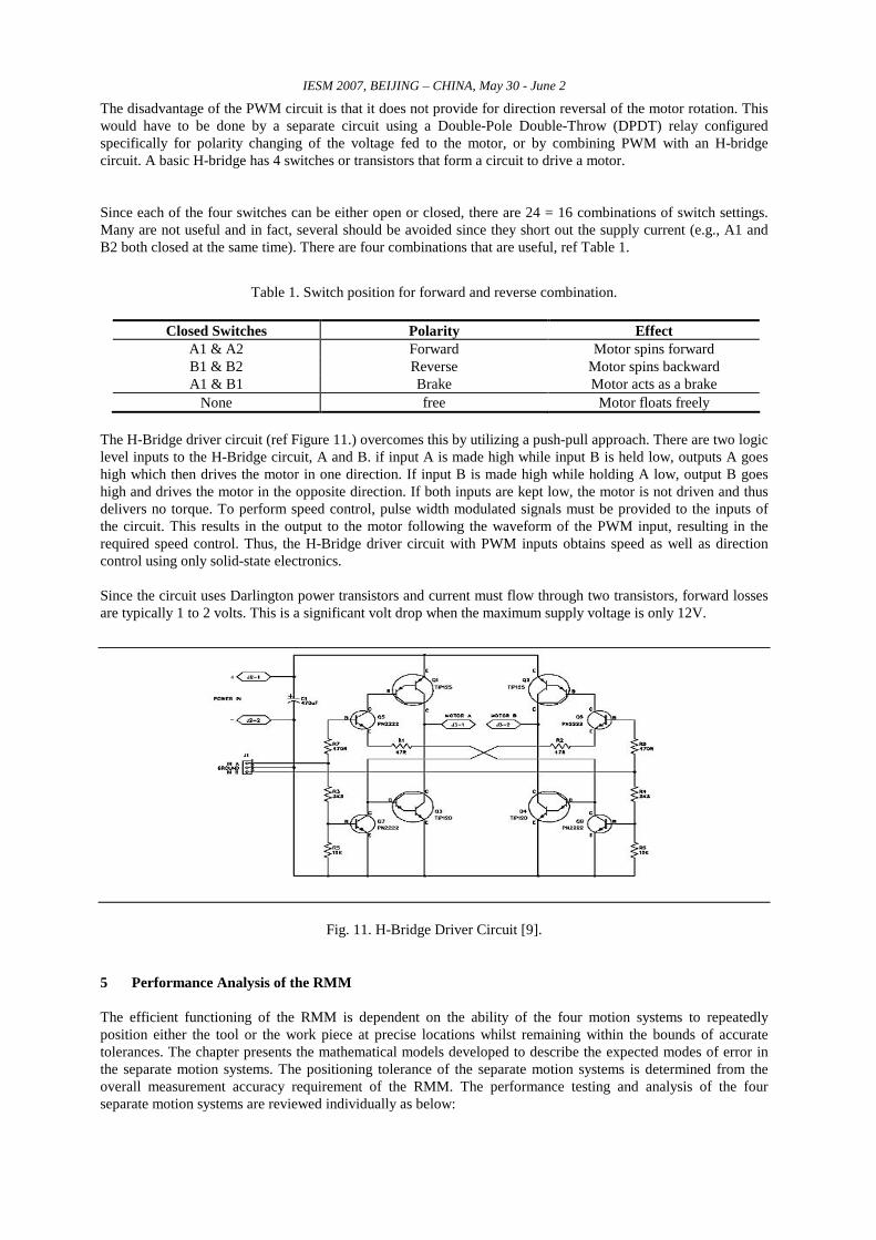
None free Motor floats freely The H-Bridge driver circuit (ref Figure 11.) overcomes this by utilizing a push-pull approach. There are two logic level inputs to the H-Bridge circuit, A and B. if input A is made high while input B is held low, outputs A goes high which then drives the motor in one direction. If input B is made high while holding A low, output B goes high and drives the motor in the opposite direction. If both inputs are kept low, the motor is not driven and thus delivers no torque. To perform speed control, pulse width modulated signals must be provided to the inputs of the circuit. This results in the output to the motor following the waveform of the PWM input, resulting in the required speed control. Thus, the H-Bridge driver circuit with PWM inputs obtains speed as well as direction control using only solid-state electronics. Since the circuit uses Darlington power transistors and current must flow through two transistors, forward losses are typically 1 to 2 volts. This is a significant volt drop when the maximum supply voltage is only 12V.
Fig. 11. H-Bridge Driver Circuit [9].
5 Performance Analysis of the RMM
The efficient functioning of the RMM is dependent on the ability of the four motion systems to repeatedly position either the tool or the work piece at precise locations whilst remaining within the bounds of accurate tolerances. The chapter presents the mathematical models developed to describe the expected modes of error in the separate motion systems. The positioning tolerance of the separate motion systems is determined from the overall measurement accuracy requirement of the RMM. The performance testing and analysis of the four separate motion systems are reviewed individually as below:
IESM 2007, BEIJING – CHINA, May 30 - June 2 � the efficiency of the APTS to move the parts from / back the conveyor and to position parts on the APLS. � the efficiency of the APC/RS to clamp the parts from the APLS and to rotate the parts as required angle. � the efficiency of the APLS to move the parts to the required height. � the efficiency of the ATCS to move the tool box from X-Y-Z axis and to position the tool at the right place
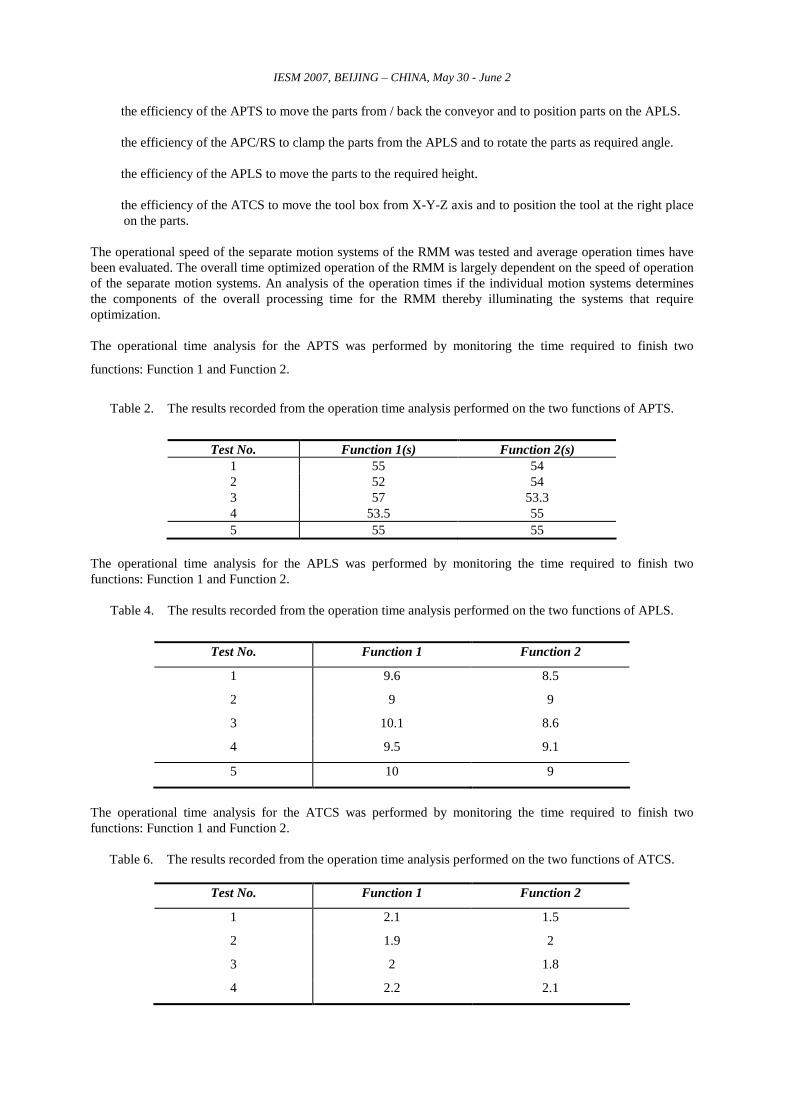
on the parts. The operational speed of the separate motion systems of the RMM was tested and average operation times have been evaluated. The overall time optimized operation of the RMM is largely dependent on the speed of operation of the separate motion systems. An analysis of the operation times if the individual motion systems determines the components of the overall processing time for the RMM thereby illuminating the systems that require optimization. The operational time analysis for the APTS was performed by monitoring the time required to finish two
functions: Function 1 and Function 2.
Table 2. The results recorded from the operation time analysis performed on the two functions of APTS.
Test No. Function 1(s) Function 2(s)
1 55 54 2 52 54 3 57 53.3 4 53.5 55 5 55 55
The operational time analysis for the APLS was performed by monitoring the time required to finish two functions: Function 1 and Function 2.
Table 4. The results recorded from the operation time analysis performed on the two functions of APLS.
Test No. Function 1 Function 2
1 9.6 8.5
2 9 9
3 10.1 8.6
4 9.5 9.1
5 10 9
The operational time analysis for the ATCS was performed by monitoring the time required to finish two functions: Function 1 and Function 2.
Table 6. The results recorded from the operation time analysis performed on the two functions of ATCS.
Test No. Function 1 Function 2
1 2.1 1.5
2 1.9 2
3 2 1.8
4 2.2 2.1
IESM 2007, BEIJING – CHINA, May 30 - June 2 5 2 2
6 Conclusion
The RMM has been developed as a reconfigurable, PC-based technology that implements modular mechanical structure and modular mechatronics control system. The RMM was developed using an alternative modular design approach, including modular mechanical structure design and modular mechatronics control system design, which resulted in the separate development of four motion systems used to implement the advanced reconfigurable manufacturing. The coordinated interaction of the APTS, the APLS, the APC/RS and the ATCS enables the RMM to position the work piece at the right place and then accurately position the tool on the work piece and machine it from multiple sides. The RMM was developed as an autonomous technology that implements a PC-based digital I/O control system to control, sequence and coordinate the interaction of the four motion systems to perform the standard routines were developed and coded in Microsoft Visual Basic 6 (VB 6). The graphical user interface with which the RMM is operated was also developed in VB 6. The structure of the digital I/O system and the development of the control algorithms implemented for the RMM were discussed. The RMM has been developed as an in-line technology that could be able to perform in-process verification tasks in the reconfigurable agile manufacturing environment. The RMM was therefore developed to exhibit a high level of reconfigurability in its capability to integrate with RMS. The two key design factors that guarantee this level of reconfigurability are the modular mechanical structure and the modular mechatronic control system. The combination of these factors results in simple integration, or relocation, of the RMM in the RMS.
7 References
[1] Felton Bob., 2001, Experts Agree: Mass Customization is Almost Here, Journal of Future Factory, NO.4, pp.45-47.
[2] Fulkerson Dill., 1997, A response to dynamic change in the market place, Decision Support System 21(3), 199-214.
[3] Goebel, P., 2005, Reconfigurable Manufacturing Systems, Proceeds of the International Conference on Competitive Manufacturing, COMA’04, Stellenbosch, South Africa, pp.69-79.
[4] Graowski, R, Navarror-Serment, LE, Paredis, C, Khosla., 2002 Institute PK heterogeneous Teams of Modular Robots, Robot Teams, edited by T Balch and L Parker, Carnegie Mellon University.
[5] Koren, Y., and Kota, S., 1999, Reconfigurable Machine Tools. U.S. Patent 5,943,750.
[6] Krar, S, Arthur, G., 2003, Exploring Advanced Manufacturing Technologies, New York: Industrial Press.
[7] Landers, R.G., July 23-26 2000, A New Paradigm in Machines Tools: Reconfigurable Machine Tools.
[8] Moon Y.M., and Kota,S., 1998, Generalized Kinematic Modelling Method for Reconfigurable Machine Tools, Proc. 25th Biannual Mechanism Design Conference, Atlanta, GA.
[9] Mayor R., 2000, Phd Thesis : Automated Visual Inspection Apparatus for Flexible Manufacturing System, University of Natal, Durban South Africa.
[10] Ostia D.I.Nwokah, Yildirim Hurmuzlu, 2002, The Mechanical System Design Handbook-Modeling, Measurement and Control by CRC Press LLC, Southern Methodist University, Dallas, Texas, USA.
[10] Pine Joseph, 1993, Mass Customization: The new frontier in business competition, Harvad Business School Press, Boston, MA.
[11] Potgieter, J., Bright, G., 2002, Modular Mechatronic Contorl System for Internet Manufacturing, Proceeds of the 18th international on CAD/CAM, Robotics and Factories of the Future, Potor, Spain, pp529-536.
[12] Reuven Katz, Yong-Mo Moon, 2000, Virtual Arch Type Reconfigurable Machine Tool Design, Principles and Methodology, The University of Michigan, NSF ERC for RMS Ann Arbor, MI 48109.
[14] Ruddy Mary, 2002, Mass Customization Now Closer Than Ever, Journal of Machine Design, No.6, pp. 59-61.
[15] The Eagle Appliances South Africa (Pty) Ltd, 2006, http://www.eagle.co.za, http://www.eagledaq.com