Embed Size (px)
Citation preview

Matkar Ashish Devidas, Shelke R .D, Deshpande H. N.; International Journal of Advance Research and Development.
© 2017, www.IJARND.com All Rights Reserved Page | 7
(Volume2, Issue10) Available online at www.ijarnd.com
Design and Analysis of Vertical Evaporator Refrigerator
without Freezer Compartment Ashish Devidas Matkar, R. D. Shelke, H. N. Deshpande
1Student, 23Professor 123Mechanical Engineering Heat Power
123PES Modern College of Engineering, Pune, India.
[email protected], [email protected], [email protected]
ABSTRACT
The aim of this paper is to design analysis of Regular 190L household direct cool vertical evaporator refrigerator with refrigerant
134a. In this household refrigerator. The usable cabinet space is improved by 25~30 % with roll bond vertical evaporator by instead
of conventional c or o type roll bond evaporator. This improvement in usable space is based on the volume of existing evaporator
ie. freezer section of house hold a direct cool refrigerator. The design finalization of cooling circuit and internal volume of the
vertical evaporator is done based on 43° no load pull-down test and 32°C energy test. Based on 43°C pull-down test, freezer section
becomes warmer by approximately 9°C~12°C so it can be considered as a refrigerator without a freezer compartment. A further
extension this vertical evaporator, one perforated cover is added to this bare roll bond panel of vertical evaporator from customer
safety and aesthetic point of view and this vertical evaporator refrigerator with 1 perforated cover then compared with baseline
refrigerator. The energy improvement found with vertical evaporator refrigerator with 1 perforated cover when compared to
baseline refrigerator is 9~10 %.
Keywords: Vertical Evaporator, Roll Bond Evaporator, Direct Cool Refrigerator, R134a.
1. INTRODUCTION
The usable cabinet space of household direct cool refrigerator is improved by use of roll bond vertical evaporator instead of
conventional c or o type roll bond evaporator.
This usable space decided based on the volume of existing evaporator i.e. freezer compartment and refrigerator compartment
however in this project freezer compartment is converted into the refrigerator compartment.
In this project for R190L refrigerator 3 cooling circuits based on their internal volumes 120CC, 140CC & 170CC are designed and
analyzed. The energy improvement found in R190L 170CC vertical evaporator refrigerator is 3~6 % compared to its 120CC &
140CC vertical evaporator refrigerators, so based on 43°C NLPD and 32°C energy tests 170CC internal volume circuit is considered
as a final cooling circuit.
As per Bureau of energy efficiency (BEE) guidelines, in 43°C NLPD test freezer compartment temperature should be colder than -
8°C temperature, which is not reaching in case of vertical evaporator refrigerator so it can be registered under ‘refrigerator without
freezer compartment’ category.
Further perforated sheets are added to cover bare roll bond panel ie evaporator, in which 170CC cooling circuit with 1 perforated
cover found the most energy efficient. Then comparative 43°C NLPD and 32°C energy tests are done on baseline R190L refrigerator
and R190L 170CC cooling circuit with 1 perforated cover ie vertical evaporator refrigerator. The energy improvement found in
vertical evaporator refrigerator is 9~10 % compared to baseline refrigerator.
2. LITERATURE REVIEW
A first-principles mathematical model developed to investigate the thermal behavior of a plate-type, roll-bond evaporator by
Christian J. L Hermesa, et.al [1]. The refrigerated cabinet was also taken into account in order to supply the proper boundary
conditions to the evaporator model. The mathematical model was based on the mass, momentum, and energy conservation principles
applied to each of the following domains: (i) refrigerant flow through the evaporator channels; (ii) heat diffusion in the evaporator
plate; and (iii) heat transmission to the refrigerated cabinet. Empirical correlations were also required to estimate the shear stresses,

Gupta Gagan, Sugumaran .S; International Journal of Advance Research and Development.
© 2017, www.IJARND.com All Rights Reserved Page | 8
and the internal and external heat transfer rates. The governing partial differential equations were discretized through the finite
volume approach and the resulting set of algebraic equations was solved by successive iterations. Validation of the model against
experimental steady-state data showed a reasonable level of agreement: the cabinet air temperature and the evaporator cooling
capacity were predicted within error bands of 1.5 C and 6%, respectively. This paper helps to investigate the thermal behavior of a
plate-type, roll-bond evaporator. This paper doesn’t give any idea regarding design and analysis of a vertical roll bond evaporator.
In international engineering research journal paper by Ashish Matkar, et.al [2] the design and analysis of direct cool refrigerator
with vertical evaporator is studied. In this paper effect of vertical evaporator on performance in the household refrigerator instead
of conventional O or C type evaporator is studied but the experimentation and analysis are done with R134a refrigerant whereas
impact with R600a refrigerant is not discussed.
The investigation was done by Erik Bjo rk, et.al [3] for the flow boiling heat transfer in a typical domestic refrigerator evaporator
with horizontal flow, frequent bends, and a non-circular cross-section. The mass flux was varied between 21 and 43 kg/m2 s, the
heat flux between 1 and 5 kW/m2 and the vapor quality between 0.2 and 0.8. In spite of a predicted stratified to wavy-stratified flow
pattern complete tube perimeter wetting was believed to occur except for the lowest mass flux and for positions upstream of the first
bend. It was concluded that the bends helped to wet the tube perimeter. The experimental data revealed heat transfer coefficients
higher than predicted with conventional correlations. This was suggested to be explained by thin film evaporation at a perimeter
repeatedly wetted by liquid slugs. A simple correlation based on the pure convective part of the Shah correlation was derived from
the experimental data. The mean deviation of this was 16.9% compared to Shah’s 54.7%. This paper helps to investigate the flow
boiling heat transfer in a typical domestic refrigerator evaporator with horizontal flow, frequent bends, and a non-circular cross-
section. This paper doesn’t give any idea regarding design and analysis of a vertical roll bond evaporator.
A study is presented on the influence of the air flow rate and surface geometry on the thermal-hydraulic performance of
commercial tube-fin ‘no-frost’ evaporators by Jader R. Barbosa JR. et.al [4]. A specially constructed wind-tunnel calorimeter was
used in the experiments from which data on the overall thermal conductance, pressure drop, Colburn j-factor and Darcy friction
factor f were extracted. Eight different evaporator samples with distinct geometric characteristics, such as the number of tube rows,
number of fins and fin pitch were tested. Semi-empirical correlations for j and f are proposed in terms of the air-side Reynolds
number and the finning factor. A discussion is presented on the performance of the evaporator with respect to specific criteria such
as the pumping power as a function of heat transfer capacity and the volume of material in each evaporator. This paper helps to
study influence of the air flow rate and surface geometry on the thermal-hydraulic performance of commercial tube-fin ‘no-
frost’ evaporators. This paper doesn’t give any idea regarding design and analysis of a vertical roll bond evaporator.
The presentation of a new model for fin-and-tube evaporators, focusing on the solid core simulation and its integration with a quasi-
homogeneous two-phase flow model for the in- tube refrigerant flow was done by C. Oliet, et.al [5]. Special attention is given to
separate in-tube flow patterns (stratified, stratified- wavy), because of their importance in liquid overfeed and domestic refrigerator
evaporators and the impact on the solid core temperature distribution. The paper presents the solid core formulation and numerical
method, the in-tube two-phase flow model, and describes the proposed integration algorithm between them. A selected single-
tube baseline case is analysed in full detail, showing the impact of stratified flow on the fin-and-tube temperature distributions.
Additional studies are finally presented analysing different flow transitions (single phase to stratified flow, stratified-wavy flow to
annular flow, and annular flow to partial dry-out) and several operating parameters (flow regime, tube material, and tube thickness).
This paper is devoted to the presentation of a new model for fin-and-tube evaporators, focusing on the solid core simulation and its
integration with a quasi-homogeneous two-phase flow model for the in- tube refrigerant flow. This paper doesn’t give any idea
regarding design and analysis of a vertical roll bond evaporator.
The study was done by Anand M. Shelke, et.al [6] on the design of solar sterilizer assisted with aqua ammonia solar vapour
absorption system. The projects deal with the fulfillment of sterilized safe drinking water at cheap & reliable cost as well as usage
of nonconventional solar energy source. It consists of a combined system having water sterilizer that usage evacuated tubes and
aqua ammonia vapour absorption system.
The study was done by Sandip S. Sisat, et.al [7] on performance and evaluation of blends of hydrocarbon (R134a/R290 and
R134a/R600a) in the household refrigerator as hydrocarbon are the best-suited fluid for alternatives to conventional refrigerants.
The study was done for usage of blends of R134a/R290 and R134a/R600a for experimentation at the different mass percentage of
refrigerants for different load conditions.
3. HEAT LOAD CALCULATIONS FOR DIRECT COOL REFRIGERATOR WITHOUT FREEZER COMPARTMENT
Below are the steps defined to make the design calculations for the refrigerator. All the design calculation for the refrigerator is
based on heat and mass transfer fundamentals.
Step 1- Calculation of outside Heat Transfer Coefficient (ho)
Step 2- Calculation of Internal Heat Transfer Coefficient (hi)
Step 3 -Wall Heat Load Calculations
Step 4 - Air Change Load Calculations
Step 5 - Calculations for Commodity Load for Refrigerator Compartment
Step 6 - Calculations for Commodity Load for Freezer Compartment
Step 7 - Calculation of Water Load for RC

Gupta Gagan, Sugumaran .S; International Journal of Advance Research and Development.
© 2017, www.IJARND.com All Rights Reserved Page | 9
Step 8 - Calculations for Water Load for FC
Step 9 - Total Heat Load with freezer compartment
Step 10 - Total Heat Load without freezer compartment
Step 11 –Comparison of Total Heat Load with and without freezer
Detail explanation of each step:
Step 1- Calculation of outside Heat Transfer Coefficient (ho) On Condenser Coil
For outside heat transfer calculation, outer wall temperature is considered based on air-cooled condenser temperature and ambient
temperature. For calculating heat transfer coefficient calculated Grasoff No as per given formula. Value of Prandtl No (Pr) is taken
from property table and calculated outside heat transfer coefficient based on below formula. Table 3.1 shows the calculated values
of outside heat transfer coefficient.
Gr =g×β×θ×L3
ϑ2 ------------3.1
Nu = 0.548(Gr × Pr)1/4 ----------3.2
When 105 < Gr. Pr > 1011
Nu = ho × L/K -----------3.3
Table 3.1: Calculation of outside Heat Transfer Coefficient (ho)
Twall = 47°C
Tamb = 43°C
Tmean = 45°C
Taking properties of air at 45°C
ho = 3.6
Step 2- Calculation of Internal Heat Transfer Coefficient (hi)
For inside heat transfer calculation inside wall, temperature is considered based on evaporator temperature and inside surface
temperature. For calculating heat transfer coefficient Reynolds No (Re) and Prandtl No (Pr) is taken from property table and
calculated inside heat transfer coefficient based on below formula.
g=acceleration due to Earth gravity
β=volumetric thermal expansion coefficient (equal to approximately 1/T, for ideal gases,
Where
This absolute temperature)
Ts= Surface temperature
T∞= bulk temperature
L=characteristic length
D=diameter
V=kinetic viscosity
Nu = 0.548 ×(Gr × Pr)1
4 . . . . . . . . . . for 105 < 𝐺𝑟 × Pr < 1011
--------3.5
Internal Heat Transfer Coefficient (hi) based on natural convection.
T liner FC = -13°C
T in FC = -12°C
T mean FC = -12.5°C
T liner RC = +2°C
T in RC = +1°C
T mean RC = +1.5°C
Taking properties at -12.5 mean air temperature.
hi for FC = 1.423
hi for RC = 1.391
Step 3 -Wall Heat Load Calculations
Wall load calculations are finalized on the basis of required refrigerator capacity, performance, and energy requirement for the
refrigerator. As shown in Table 3.1 inside and outside surface area of each refrigerator and freezer walls is calculated. The thermal
resistance considering inside and outside convection and conduction for the each surface of refrigerators like liner, insulation and
sheet metal part for each wall of the refrigerator and freezer compartment is calculated. The total thermal resistance of each
refrigerator and the freezer wall is calculated. Then heat transfer of each wall of refrigerator and freezer compartment is calculated.

Gupta Gagan, Sugumaran .S; International Journal of Advance Research and Development.
© 2017, www.IJARND.com All Rights Reserved Page | 10
R1 = 1/(ho x Ao) --------3.5
R2 = bCRCA/(KCRCA x ACRCA) ------3.6
R3 = bInsulation/(KInsulation x AInsulation) ----3.7 R4 = bLiner/(KLiner x ALiner)
-----3.8
R5 = 1/(hi x Ai) ----3.9
Rt = R1 + R2 + R3 + R4 + R5 -----3.10
Q = (To − Ti)/Rt -----3.11
Figure 3.1: Resistance circuit
Table 3.1: Wall Heat Load Calculations
Walls To Ti hi ho Ao
RC Side Wall LHS 43 +2 1.3912 3.06 0.62
RC Side Wall RHS 48 +2 1.3912 3.06 0.62
RC Back Wall 48 +2 1.3912 3.06 0.88
RC Door 43 +2 1.3912 3.06 0.71
RC Bottom Wall 43 +2 1.3912 3.06 0.23
Comp. Deck-Depth 43 +2 1.3912 3.06 0.10
Comp. Deck-Height 43 +2 1.3912 3.06 0.12
FC Top Wall 43 -
12 1.423 3.06 0.34
FC Side Wall LHS 48 -
12 1.423 3.06 0.33
FC Side Wall RHS 48 -
12 1.423 3.06 0.33
FC Back Wall 53 -
12 1.423 3.06 0.36
FC Door 43 -
12 1.423 3.06 0.29
Table 3.2: Wall Heat Load Calculations
Walls R
total
Q
(watts)
RC Side Wall LHS 5.17 9.48
RC Side Wall RHS 5.22 10.35
RC Back Wall 5.12 10.54
RC Door 5.26 9.31
RC Bottom Wall 12.69 3.86
Comp. Deck-Depth 34.27 1.43
Comp. Deck-Height 29.70 1.65
FC Top Wall 11.02 5.53
FC Side Wall LHS 13.34 4.95
FC Side Wall RHS 13.34 4.95
FC Back Wall 14.08 5.04
FC Door 15.13 4.03
Total Thermal Wall Heat Load (W) = 69.54 Watts.
Step 4 - Air Change Load Calculations

Gupta Gagan, Sugumaran .S; International Journal of Advance Research and Development.
© 2017, www.IJARND.com All Rights Reserved Page | 11
Air change load is calculated based on outside and inside humidity ratio and also considered sensible heat and latent heat. Table 3.4
shows the input values of temperatures and calculated values of inside humidity, outside humidity, sensible heat transfer, latent heat
transfer and the total heat transfer due to air change. Eqs.(3.12) and Eqs. (3.13) Shows the formula to calculate sensible heat transfer
and latent heat transfer respectively.
Qs = ρ ∗ QAir ∗ Cp(To − Ti) -------3.12
Ql = ρ ∗ QAir ∗ Cp(Wo − Wi) ------ 3.13
For FC
Air change Load = V x Air x 0.75 x (hi –ho) /24
= 3 x 36 x 0.75 x (5.66-3.06) /24
=8.7 BTU/hr
Air change Load = 2.54 Watts
For RC
Air change Load = V x Air x 0.75 x (hi –ho) /24
= 9 x 36 x 0.75 x (5.66-3.06) /24
=3.84 BTU/hr
Air change Load = 6.38 Watts.
Step5- Calculations for commodity load for Refrigerator compartment
Q= {weight of commodity (lb) x delta T°C x Sp. Heat ((btu/lb)/F) } / 24
= 9.027 Watts ---------3.14
Table 3.3 shows the commodities taken in Consideration based on consumer’s normal usage and its weight based on storage space
available in the refrigerator compartment. The normal temperature of a commodity is considered as 30°C and storage temperature
of each type of commodity defined based on dew point temperature. Then the specific heat of each commodity calculated as shown
in the formula in Eqs. (3.14). Then heat transfer rate of each commodity for refrigerator compartment is calculated.
For RC:
Table 3.3: Commodity Load for RC
Sr No Commodity Q Watts
1 cabbage 0.994967
2 carrots 0.762102
3 cucumber 0.363782
4 tomatoes 0.867735
5 Apples 0.857768
6 coconut 0.585869
7 Lemon 0.314878
8 Grapes 0.868702
9 water 1.681739
10 milk 0.910289
11 fish 0.819421
Total Commodity load in RC (W) = 9.02725 Watts.
----3.14
Step 6 - Calculations for Commodity Load for Freezer Compartment.
Table 3.4 shows the commodities taken in consideration based on consumer’s normal usage and its weight based on storage space
available in the freezer compartment. The normal temperature of a commodity is considered as 30 ℃and storage temperature of
each type of commodity is defined based on dew point temperature. Then the specific heat of each commodity is calculated as shown
in the formula in Eqs. (3.15). Then latent heat conversion is considered since in freezer compartment phase change happens at 0℃.
Then heat transfer rate of each commodity for freezer compartment is calculated.
Q= { weight of commodity (lb) x delta T°C x Sp. Heat ((Btu/lb)/F) +Lt. heat (Btu/lb) } / 24
= 923.10 Watts ---------3.15
For FC:

Gupta Gagan, Sugumaran .S; International Journal of Advance Research and Development.
© 2017, www.IJARND.com All Rights Reserved Page | 12
Table 3.4: Commodity Load for FC
Sr No Commodity Watts
1 Meat 1.854577
2 Chicken 2.39398
3 Ice cream 5.798294
4 Ice 13.05632
Step 7 - Calculation of Water Load for RC
Water load for refrigerator compartment is calculated based on the normal water temperature of 30℃ to the drinkable water
temperature of 13℃. The amount of water quantity considered based on storage space available and normal usage pattern of the
consumer. The total heat transfer rate for water in refrigerator compartment is calculated
Q= {weight of water (lb) x delta T°C x Sp. Heat ((Btu/lb)/F) } / 24
= 14.76 Watts ---------3.16
Step 8 - Calculations for Water Load for FC
Water load for freezer compartment is calculated based on the normal water temperature of 30℃ to the ice temperature of -5℃. The
amount of water quantity considered based on storage space available and normal usage pattern of the consumer. Then latent heat
conversion is considered since in freezer compartment phase change happens at 0℃. The total heat transfer rate for water in the
freezer compartment is calculated.
Q= {weight (lb) x delta T°C x Sp. Heat ((Btu/lb)/F) x weight of water (lb) x Lt. Heat (Btu/lb)} / 24
---------3.17
For FC
Q = (wt x delta T x Sp) + (wt x latent heat) / 24 3.18
= { 7.04 × [30 - (-4)] × 1 + 7.04 × 144 } /24 = 15.28 W
For RC
Q = (wt x delta T x Sp) + (wt x latent heat) / 24 3.19
= { 31.9 × [30 - (13)] × 1 + 31.9 × 144 } /24 = 6.612 W
For Chiller
Q = { 4.4 × [30 - (1.5)] × 1 + 4.4 × 144 } /24 = 1.52 W 3.20
Total water commodity load = 23.42 Watts.
Step 9 - Total Heat Load (W) with freezer compartment
The total heat load to be handled in the refrigerator is the sum of heat from sources as:
Heat load from walls
Heat load from entering air i.e. Air change load
Heat load from commodity load
Heat load from water and ice
Table 3.5 shows the total thermal load of freezer and refrigerator compartment. Total thermal load for the 190L conventional
refrigerator is 137.08 watts.
Table 3.5: Total Thermal Load for Refrigerator (with freezer compartment)

Gupta Gagan, Sugumaran .S; International Journal of Advance Research and Development.
© 2017, www.IJARND.com All Rights Reserved Page | 13
Sr.
No Parameters
Q-FC
(W)
Q –RC
(W)
Q Total
(W)
1 Thermal
Wall Load 6.14 63.12 69.26
2 Air Change
Load 2.54 3.84 6.38
3 Commodity
Load 23.10 9.02 32.12
4 Water Load 15.28 14.76 30.04
Total heat Load (W) 137.08
As per heat load for given platform size, we can select the compressor from compressor manufactures catalogs to achieve cooling
performance as per requirement and energy target for that cooling target, next we select the condenser and evaporator for given data
of heat load.
In this project, focus is on condenser selection and improvement in condenser performance improvement from given data by keeping
all parameter constant like compressor, platform size, evaporator, capillary length, heat load.
Step 10 - Total Heat Load (W) without freezer compartment
The total heat load to be handled in the refrigerator is the sum of heat from sources as:
Heat load from walls
Heat load from entering air i.e. Air change load
Heat load from commodity load
Heat load from water and ice
Table 3.6 shows the total thermal load of freezer and refrigerator compartment. Total thermal load for the 190L conventional
refrigerator is 96.88 watts.
Table 3.6: Total Thermal Load for Refrigerator (without freezer compartment)
Sr.s No Parameters
Q-
FC
(W
Q –RC (W) Q Total (W)
1 Thermal
Wall Load 6.14 63.12 69.26
2 Air Change
Load 0 3.84 3.84
3 Commodity
Load 0 9.02 9.02
4 Water Load 0 14.76 14.76
Total heat Load (W) 96.88
Step 11 – Comparison Total Heat Load (W) without freezer compartment
As from step 10 and Step 11 it is clear that, total heat load of the refrigerator without freezer compartment is less than total heat load
of the refrigerator without freezer compartment so no need to change compressor specification in terms of cooling capacity and
COP.
Step 12 – Selection of R134a compressor
Based on table 3.7, selected LGE MA42LPJG R134a compressor model for testing.
Table 3.7: R134a compressor details
Compressor R134a Compressor
Make & Model LGE R134a MA42LPJG
Cooling Capacity 107 W
COP (W/W) 1.18 COP
Displacement 4.2 CC
4. Cooling circuit diagrams of vertical evaporator
Gupta Gagan, Sugumaran .S; International Journal of Advance Research and Development.
© 2017, www.IJARND.com All Rights Reserved Page | 14
Figure 4.1: Roll bond panel circuit diagram _ 120CC circuit
Figure 4.2: Roll bond panel circuit diagram _ 140CC circuit
Figure 4.3: Roll bond panel circuit diagram _ 170CC circuit
5. Experimental setup: In the proposed scenario, freezer section is removed and it is converted into usable refrigerator compartment as shown in figure 5.1.
Figure 5.1: Vertical evaporator
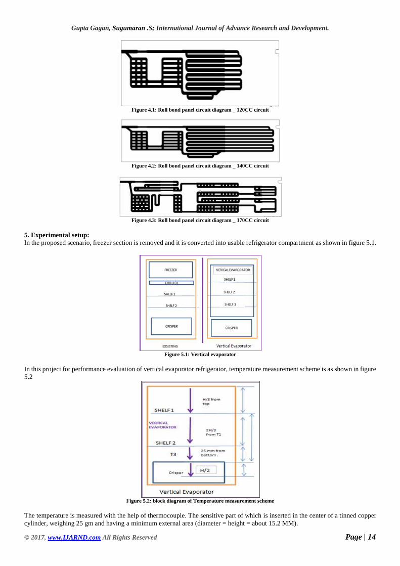
In this project for performance evaluation of vertical evaporator refrigerator, temperature measurement scheme is as shown in figure
5.2
Figure 5.2: block diagram of Temperature measurement scheme
The temperature is measured with the help of thermocouple. The sensitive part of which is inserted in the center of a tinned copper
cylinder, weighing 25 gm and having a minimum external area (diameter = height = about 15.2 MM).

Gupta Gagan, Sugumaran .S; International Journal of Advance Research and Development.
© 2017, www.IJARND.com All Rights Reserved Page | 15
Temperature measuring instruments shall be accurate ±0.3°C .K type’s thermocouples are used to measure temperature inside
cabinets
6. Test matrix:
The tests as per mentioned in Indian Std. S1476 are performed on R190L vertical evaporator and R190L baseline refrigerator.
Based on functional & subject matter experience, 43°C NLPD and 32°C energy tests are selected for experimentation from the
above mentioned standard.
Table 6.1: Experimentation test matrix
Sr.
No
Variation in cooling circuit selected for
experimentation
1 R190L
120CC
R190L
140CC
R190L
170CC ***
2
R190L
170CC
W/O
perforated
cover
R190L
170CC
with 1 P.
cover
R190L
170CC
with 2 P.
covers
R190L
170CC
with 3 P.
covers
3
R190L
Baseline
product
R190L
170CC
W/O P.
cover
R190L
170CC
with 1 P.
cover
***
7. RESULTS & DISCUSSION In this chapter, results are discussed from cooling circuit selection based on its internal volume for vertical evaporator up as per
mentioned in test matrix table no.6.1.
7.1.1 43°C no load pull-down test
43°C no load pull-down test helps to select the refrigerant type based on compartment’s temperature.
The internal volume of R190L baseline refrigerator roll bond panel ie o type evaporator is 165CC, which is taken into consideration
for below-mentioned comparison testing.
Table 7.1: 43°C NLPD test results
Circuit Volume and Gas
charging qty.
R190L Vertical
Evaporator
120CC (~30%
less than final)
R190L Vertical
Evaporator
140CC (~20%
less than final)
R190L Vertical
Evaporator
170CC
(Final circuit)
R134a : 50 gm R134a : 60 gm R134a : 70 gm
Freezer Avg. 6 hr. (°C) NA NA NA
Refrigerator Avg. 6 hr.
(°C) -0.9 -1.7 -3.9

Gupta Gagan, Sugumaran .S; International Journal of Advance Research and Development.
© 2017, www.IJARND.com All Rights Reserved Page | 16
Figure 7.1: 43°C NLPD comparison to select internal volume of cooling circuit based on refrigerator compartment’s temperature
Figure 7.2: 43°C NLPD comparison to select internal volume of cooling circuit based on crisper compartment’s temperature
1) In R134a R190L 170CC internal volume vertical evaporator refrigerator, overall refrigerator compartment’s 6th-hour temperature
is drifted to -3.9°C which is colder compared to 120CC & 140CC internal volume vertical evaporator refrigerators.
2) In R134a R190L 170CC internal volume vertical evaporator refrigerator, crisper compartment’s 6th-hour temperature is drifted
to +1.1°C which is colder compared to 120CC & 140CC internal volume vertical evaporator refrigerators.
7.1.2 32°C Energy test comparison
32°C energy test helps to select energy efficient product on basis of per year energy consumption between R134a & R600a
refrigerant products.
Table 7.2: 32°C Energy Test Results
Cooling
circuits
120CC (30%
Less)
140CC(20%
less)
170CC
(Final
circuit)
Test W.pt. C.pt. W.pt. C.pt. W.pt Cpt.
Individual
Energy/
Year
(Kwh)
250 279 245 272 240 265
Final
Energy/
Year
(Kwh)
275 266 258
-0.9
-1.7
-3.9-4
-3
-2
-1
R190L V.E.120CC
R190L V.E.140CC
R190L V.E. 170CC
Ref
rige
rato
rco
mp
arte
nt'
s
6th
hr
av
g. t
emp
erat
ure
Refrigerator Avg.6th hr.
3.5
2.9
1.11
1.5
2
2.5
3
3.5
R190L V.E.… R190L V.E.… R190L V.E.…
Cri
sper
co
mp
arte
nt'
s 6
th h
r
aver
age
tem
per
atu
re
Crisper Avg.6th hr.

Gupta Gagan, Sugumaran .S; International Journal of Advance Research and Development.
© 2017, www.IJARND.com All Rights Reserved Page | 17
Figure 7.3: 32°C warm & cold pt. energy comparison test to select the internal volume of the cooling circuit
Figure 7.4: 32°C final energy comparison test to select internal volume of cooling circuit
1) In 32°C energy test, R134a R190L vertical evaporator refrigerator with 170CC internal volume circuit consumes less energy ie
258 KWH/year compared to 275 KWH/ year in 120 CC circuit and 266 KWH/ year in140 CC circuit.
2) So based on 43°C NLPD & 32°C energy test 170CC internal volume cooling circuit is considered for further experimentation as
it most efficient compared to other 2 cooling circuits.
7.2 Comparison to select addition of perforated covers
Perforated covers are added to cover bare roll bond panel cooling circuit ie evaporator from aesthetic & customer safety point.
This is to select addition of perforated covers ie thickens to cover vertical evaporator.
The material used for Perforated cover = HIPS with sheet thickness 1.2 MM.
7.2.1 43°C No load pull down comparison
43°C no load pull-down test helps to select perforated cover thickness over vertical evaporator based on compartment’s temperature.
Table 7.3: 43°C NLPD test results
Circuit
Volume and
Gas charging
qty.
R190L
170CC
circuit
V.E.
W/O
P.
cover
R190L
170CC
circuit
V.E
with 1
P.
cover
R190L
170CC
circuit
V.E. with
2 P.
covers
R190L
170CC
circuit
V.E.
with 3 P.
covers
R134a
: 70
gm
R134a
: 70gm
R134a :
70gm
R134a :
70gm
Freezer Avg.
6 hr. (°C) NA NA NA NA
Refrigerator
Avg. 6 hr.
(°C)
-3.9 -3.2 -2.2 -1.3
250
279
245
272
240
265
235
240
245
250
255
260
265
270
275
280
Warmpt.
Cold pt. Warmpt.
Cold pt. Warmpt.
Cold pt.
R190L VE 120CC R190L VE 140CC R190L VE 170CCY
earl
y E
C (
KW
H/Y
ear)
EC /Yr(KWh/Yr.)
275
266
258
245
250
255
260
265
270
275
280
120CC 140CC 170CC
Yea
rly
EC
(K
WH
/Yea
r)
EC /Yr(KWh/Yr.)

Gupta Gagan, Sugumaran .S; International Journal of Advance Research and Development.
© 2017, www.IJARND.com All Rights Reserved Page | 18
Figure 7.5: 43°C NLPD comparison to select addition of perforated covers based on refrigerator compartment’s temperature
Figure 7.6: 43°C NLPD comparison to select addition of perforated covers based on crisper compartment’s temperature
1) In R134a R190L 170CC vertical evaporator, overall refrigerator compartment’s 6th-hour temperature is drifted to -3.2°C which
is colder compared to 2 & 3 perforated cover refrigerators with 1 perforated cover refrigerator
2) In R134a R190L 170CC vertical evaporator with 1 perforated cover refrigerator, crisper compartment’s 6th-hour temperature is
drifted to +2°C which is colder compared to 2 & 3 perforated cover refrigerators.
3) As both, refrigerator compartment's & crisper compartment’s 6 hr. avg. temperatures are colder in the 170CC vertical evaporator
with 1 perforated cover refrigerator compared to other 2 perforated cover options so only 1 perforated cover option is further
considered for 32°C energy test.
7.4 Comparison of baseline product vs vertical evaporator with 1 perforated cover
This is to compare baseline product vs vertical evaporator with 1 perforated cover.
7.4.1 43°C No laod pull down comparison
Table 7.4: 43°C NLPD test results
Circuit
Volume and
Gas
charging
qty.
R190L Base
Line product
with (175
CC) O Type
evaporator
R190L
170CC
circuit
vertical
evaporator
without
perforated
cover
R190L
170CC
circuit
vertical
evaporator
with 1
perforated
cover
R134a :
75gm
R134a :
70gm
R134a :
70gm
Freezer Avg.
6 hr. (°C) -14.7 NA NA
Refrigerator
Avg. 6 hr.
(°C)
-1.7 -3.9 -3.2
-3.9
-3.2
-2.2
-1.3
-4.0
-3.5
-3.0
-2.5
-2.0
-1.5
-1.0
190L V.E.170CC W/Operforated
cover
190L V.E.170CC. with 1
perforatedcover
190L V.E.170CC with 2
perforatedcovers
190L V.E.170CC with 3
perforatedcovers
Ref
rige
rato
r c
om
par
tmen
t's
6th
hr
av
g. t
emp
erat
ure
RefrigeratorAvg.6th hr.
1.1
2.0
2.9
3.8
0
0.5
1
1.5
2
2.5
3
3.5
4
VE W/O Cover VE with 1cover
VE with 2cover
VE with 3cover
Cri
sper
co
mp
artm
ent'
s 6
th h
r
aver
age
tem
per
atu
re
Crisper Avg. 6th hr.

Gupta Gagan, Sugumaran .S; International Journal of Advance Research and Development.
© 2017, www.IJARND.com All Rights Reserved Page | 19
Figure 7.7: 43°C NLPD test comparison of R190L baseline refrigerator vs R190L 170CC vertical evaporator refrigerator based on freezer & refrigerator
compartment temperature
Figure 7.8: 43°C NLPD test comparison of R190L baseline refrigerator vs R190L 170CC vertical evaporator refrigerator based on crisper compartment
temperature
1) In R134a R190L 170CC vertical evaporator with 1 perforated cover refrigerator, overall refrigerator compartment’s 6th-hour
temperature is drifted to -3.2°C which is colder compared to R134a R190L baseline refrigerator.
2) In R134a R190L 170CC vertical evaporator with 1 perforated cover refrigerator, crisper compartment’s 6th-hour temperature is
drifted to +2.0°C which is colder compared to R134a R190L baseline refrigerator.
3) In R134a R190L baseline refrigerator, the coldest compartment’s temperature recorded is of freezer compartments ie -14.7°C.
But whereas in R134a R190L 170CC vertical evaporator refrigerator with 1 perforated cover, the coldest compartment’s temperature
recorded is of refrigerator compartment’s ie -3.2°C.
So the mean shift in vertical evaporator refrigerator’s compartment temperature is at -14.7°C to -3.2°C.
As per BEE guidelines, In 43°C NLPD test freezer compartment temperature should be colder than -8°C temperature, which is not
reaching in case of vertical evaporator refrigerator so it is considered as a refrigerator without a freezer compartment.
7.4.2 32°C energy test comparison Table 7.5: 32°C Energy Test results
Cooling
circuits
R190L Base
Line product
with O Type
evaporator
R190L 170CC
vertical evaporator
with 1 perforated
cover
Test W.pt. C.pt. W.pt Cpt.
Individual
Energy/ Year
(Kwh)
268 293 240 267
Final
Energy/ Year
(Kwh)
295 265
-1.7-3.9
-3.2
-14.7-15
-13
-11
-9
-7
-5
-3
-1
R190L Base LineRefrigerator
R190L V.E.170CC W/O
perforated cover
R190L V.E.170CC. with 1
perforated cover
Fre
ezer
& R
efri
gera
tor
co
mp
artm
ent'
s 6
th h
r a
ver
age
tem
per
atu
re
RefrigeratorAvg. 6th hr.
Freezer Avg.6th hr.
6.4
1.1
2.0
0
1
2
3
4
5
6
7
Base Line Ref. VE W/O cover VE with 1 cover
Cri
sper
co
mp
artm
ent'
s 6
th h
r
aver
age
tem
per
atu
re
Crisper Avg. 6thhr.

Gupta Gagan, Sugumaran .S; International Journal of Advance Research and Development.
© 2017, www.IJARND.com All Rights Reserved Page | 20
Figure 7.9: 32°C warm & cold pt. energy test comparison of R190L baseline refrigerator vs R190L 170CC vertical evaporator refrigerator with 1
perforated cover
Figure 5.10: 32°C final energy test comparison of R190L baseline refrigerator vs R190L 170CC vertical evaporator refrigerator with 1 perforated cover
1) R134a R190L 170CC vertical evaporator refrigerator with 1 perforated cover consumes less energy ie 265 kWh/year compared
to R134a R190L baseline product ie 291 kWh/year.
2) As per BEE table 2.2 The year 2015 given in annexure table no B2 & B3, R134a R190L 170CC vertical evaporator refrigerator
with 1 perforated cover shall be treated as 4 stars whereas R134a R190L baseline product shall be treated as 3 Star.
So energy improvement is 1 star in case of vertical evaporator refrigerator.
3) Based on 43°C NLPD & 32°C energy test R134a R190L 170CC vertical evaporator refrigerator with 1 perforated cover is more
efficient than R190L baseline refrigerator.
CONCLUSION
1) Freezer to refrigerator compartment volume ratio is 30:: 70%. As in R190L vertical evaporator refrigerator, freezer compartment
is converted into refrigerator compartment so it gives an improvement in refrigerator usable space by 25~30% which means larger
food storage area.
2) Based on 43°C pull-down test, as freezer section becomes warmer by 9~12°C in R190L vertical evaporator refrigerator compared
to R190L baseline refrigerator. And as per Bureau of energy efficiency (BEE) guidelines, in 43°C NLPD test freezer compartment
temperature should be colder than -8°C temperature, which is not reaching in case of vertical evaporator refrigerator so it is
considered as a refrigerator without a freezer compartment.
3) In 32°C energy test, R134a R190L vertical evaporator refrigerator with 170CC internal volume circuit consumes 3~6 % less
energy consumption compared to R190L vertical evaporator refrigerator with 120CC & 140CC internal volume circuit options.
4) In R134a R190L 170CC vertical evaporator with 1 perforated cover refrigerator, overall refrigerator compartment’s 6th-hour
temperature is drifted to -3.2°C which is colder compared to 2 & 3 perforated cover refrigerators.
5) In R134a R190L 170CC vertical evaporator with 1 perforated cover refrigerator, crisper compartment’s 6th-hour temperature is
drifted to +2.0°C which is colder compared to 2 & 3 perforated cover refrigerators.
6) In 32°C energy consumption test, R134a R190L 170CC vertical evaporator refrigerator with 1 perforated cover consumes 9~10
% less energy compared to R190L baseline refrigerator. As per guidelines are given by BEE, this vertical evaporator refrigerator
can be registered in ‘refrigerator without freezer compartment’ category for star rating programme.
268
293
240
267
235
245
255
265
275
285
295
Warm pt. Cold pt. Warm pt. Cold pt.
R190L Base Line Refrigerator R190L V.E. 170CC. with 1perforated cover
Yea
rly
EC
(K
WH
/Yea
rr)
EC /Yr (KWh/Yr.)
291
265262
267
272
277
282
287
292
Base Line R190L V.E. with 1 cover
Year
ly E
C (
KW
H/Y
ear)
Yearly EC (KWh / Year )

Gupta Gagan, Sugumaran .S; International Journal of Advance Research and Development.
© 2017, www.IJARND.com All Rights Reserved Page | 21
9. REFERENCES
[1] Christian J.L Hermesa, Cla’udio Meloa, Cezar O. R. Negra ‘A numerical simulation model for plate-type, roll-bond evaporators’
Int. J. Refrigeration 31, pp.335-347, 2008.
[2] Ashish Devidas Matkar, Prof. R. D. Shelke, Prof. H. N. Deshpande ‘Design and analysis of household direct cool refrigerator
with vertical evaporator’ International Engineering Research Journal (IERJ) Special Issue, pp.835-840, ISSN 2395-1621, June 2016.
[3] Erik Bjo RK, Bjo rn Palm ‘Flow boiling heat transfer at low flux conditions in a domestic refrigerator evaporator’ Int. J.
Refrigeration 31, pp.1021-1032, 2008.
[4] Jader R. Barbosa jr. Claudio Melo, Christian J. L. Hermes, Paulo J. Waltrich ‘A study of the air side heat transfer and pressure
drop characteristic of tube fin no frost evaporators’ Applied energy 86, pp 1484–1491, 2009.
[5] C. Oliet, C. D. Perez Segarra, J. Castro, A. Oliva ‘Modeling of fin and tube evaporators considering non-uniform in tube heat
transfer’ Int. J. thermal sciences 49, pp.692-701, 2010.
[6]Anand M. Joshi, Prof. R. D. Shelke, Prof. H. N. Deshpande ‘Design of solar water sterilizer assisted with aqua ammonia solar
vapour absorption system’, international engineering research journal, pp. 801-805, 2016.
[7] Sandip S. Sisat, Prof. S. Y. Bhosale, Prof. H. N. Deshpande ‘Experimental performance evaluation of blends of hydrocarbon
(R134a/R290 and R134a/R600a) in a household refrigerator, international engineering research journal, MECH PGCON 2017.
[8] ASHRAE, 1976. Thermo-physical Properties of Refrigerants.
[9] R S Khurmi and J K Gupta, ‘A Textbook of Refrigeration and Air Conditioning’ 3rd ed., S Chand and Company Ltsd, 2007, pp.
125-144
[10] Study material from Whirlpool University and Product development center, Whirlpool of India Ltd Ranjangoan.


![Optimization of a Dual-Evaporator Vapor Compression ...prosiding.bkstm.org/prosiding/2018/KE-32.pdf · kapiler), dan evaporator [1]. Refrigerator kompresi uap memiliki keunggulan,](https://img.pdfslide.us/doc/110x75/5e59a0267d071108a3672283/optimization-of-a-dual-evaporator-vapor-compression-kapiler-dan-evaporator.jpg)