Embed Size (px)
Citation preview
International Research Journal of Engineering and Technology (IRJET) e-ISSN: 2395-0056
Volume: 04 Issue: 08 | Aug -2017 www.irjet.net p-ISSN: 2395-0072
© 2017, IRJET | Impact Factor value: 5.181 | ISO 9001:2008 Certified Journal | Page 2253
Design and Analysis of Test rig for Rudder pedal
Ch. Hemanth kumar1, Dr. Shivarudraiah2
1PG Student, Department of Mechanical Engineering, University of Visvesvaraya College of Engineering, Bangalore, India.
2 Professor, Department of Mechanical Engineering, University of Visvesvaraya College of Engineering, Bangalore, India.
---------------------------------------------------------------------***---------------------------------------------------------------------
Abstract - Periodic maintenance of aircraft will be carried out as per the defined schedules at line maintenance. Line replaceable units are repaired by removing and testing is carried out in Automatic test equipment. As a part of base level maintenance pre-installation checks of all line replaceable units are carried out to check the serviceability of units prior to installation on aircraft. An indexing test rig is provided for mounting rudder pedal assembly is used for testing and to verify the performance of rudder pedal against specifications before installation on aircraft. However this test rig should withstand the loads acting on Rudder pedal assembly. Finite element analysis was useful to verify the test-rig design. By using computer aided technique, Test rig design is designed and the model is analysed by finite element analysis by applying suitable boundary condition and change the design according to the results. Key Words: Periodic maintenance, Line replaceable units, Test rig, Rudder pedal.
1. Introduction An indexing fixture is provided for mounting the Rudder pedal assembly and controlling the vane position. Rudder Pedals Test Equipment is used for testing Rudder Pedal assembly to verify their performance against specifications before installation on aircraft. The test equipment will generate the reference signals and measure the outputs from the linear variable differential transformer (LVDT). The Test Equipment will provide calibrated deflections to the unit under test along different axes and the output from the linear variable differential transformer will be measured and compared with required values. The unit under test have potentiometer sensors for some translational/rotational movements. The Test Equipment will provide the excitation voltage for the potentiometers and measure the outputs of the potentiometer. Both the unit under test are equipped with Artificial Feel Units (AFU) which give force feedback to the control column and the rudder pedals based on a predefined relationship between the amount of deflection of control column/rudder pedal and the expected aerodynamic forces on the respective control surfaces,
2. Objective The main objective of this project is 1. To design a Test rig to perform various tests on rudder pedal without any damage to the both test rig and rudder pedal. The design should have good load bearing capacity and is designed to withstand loads and stresses built up during testing. 2. To verify the same model by analyzing the design for stress distribution and total deformation caused in loaded condition. Meshing is done to check the accuracy of the model.
2. Analytical analysis of test rig Bending equation is
M/I = Stress/y =E/R Where M = Moment of Resistance I = Moment of inertia of the section about neutral axis. E = Young’s modulus of elasticity. R = Radius of curvature of neutral axis
= Bending stress. Referring to the bending equation,
M/I = Stress/y Stress = My/I = M / (I/y) or Stress = M/Z
Where Z = Section modulus = I/y For rectangular section of width b and depth d. Let the horizontal centroidal axis be neutral axis. Section modulus Z = Moment of inertia about the neutral axis / Distance of the most distant Point of the section from neutral axis Z = I/ymax
But Moment of inertia of rectangular section is I = bd3/12 and ymax = d/2 Z = (bd3/12) / (d/2) = bd2/6
International Research Journal of Engineering and Technology (IRJET) e-ISSN: 2395-0056
Volume: 04 Issue: 08 | Aug -2017 www.irjet.net p-ISSN: 2395-0072
© 2017, IRJET | Impact Factor value: 5.181 | ISO 9001:2008 Certified Journal | Page 2254
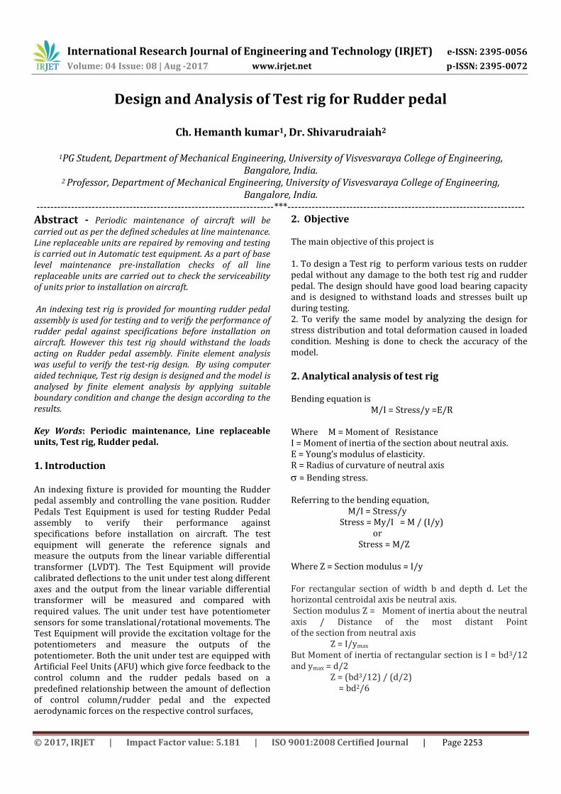
Here load 1400KN acting at pedal at a distance of e = 293 mm from the channel 1 as shown in the figure. Maximum bending stress occurs at channel 1, So calculate stress at channel 1 Bending stress at channel 1 = M / (I/y) Bending moment M = load acting on pedal * Distance between point of acting load and channel =1400*293 = 410200 N mm Now calculate moment of inertia of channel 1 Consider C section of channel 1 as shown I n the figure and calculate cross section area of the channel.
Area of whole section is Area of rectangle 1 – Area of rectangle 2 – Area of rectangle 3 Area of C section = (100*40) – (96*36) – (60*2)
= 4000 -3456-120 = 424 mm2
Component Area a (mm2)
Centroidal distance y from LL(mm)
ay (mm3)
Rectangle 1
100*40=4000 (+)
20 80000(+)
Rectangle 2
96*36 =3456 (-)
20 69120(-)
Rectangle 3
60*2 =120 (-) 39 4680 (-)
a =424 ay=6200 y’ = ay / a =6200/424 =14.62 mm IXX = IXX1 - IXX2 - IXX3 IXX1 = 100(40)3/12 + (100*40)(20-14.62)2 =649,110.9 mm4 IXX2 = 96(36)3 /12 + (96*36)(20-14.62)2 = 473,279.8mm4
IXX3 = 60(2)3 /12 + (60*2)(39-14.62)2 = 22,300.5mm4
Moment of inertia of channel = 153,530.6mm4
Distance of most distant point from neutral axis ymax = 40-14.62 =25.38mm Section modulus of channel = (I/y) =Z = 153530/25.38 =6049.27 mm3 Therefore Bending stress = Moment of resistance / Section modulus = 410,200/6049.27 = 67.80 N/mm2 Direct Stress = Load acting / cross section area of the channel = 1400/424 = 3.301 N/mm2 Total stress acting = Bending stress + Direct stress
= 71.1N/mm2.
3. Modeling of Test rig The model of test rig is designed in solidworks workbench and assembled with Rudder pedal assembly as shown in the figure.

International Research Journal of Engineering and Technology (IRJET) e-ISSN: 2395-0056
Volume: 04 Issue: 08 | Aug -2017 www.irjet.net p-ISSN: 2395-0072
© 2017, IRJET | Impact Factor value: 5.181 | ISO 9001:2008 Certified Journal | Page 2255
Fig:3.1 Test rig model
4. Test rig analysis 4.1 Static analysis
Import Test rig assembly from Solidworks and conduct structural analysis on Ansys workbench. Consider maximum stress and displacements only on test rig not on Rudder pedal assembly.
4.2 Material properties All the parts test rig assembly made up of structural steel and all parts of rudder pedal assembly made up of aluminum alloy
Properties Structural steel
Aluminium alloy
Poisson’s ratio 0.3 0.33 Young’s modulus (Pa)
2*1011 7.1*1010
Density (kg/m3) 7850 2770 4.3 Boundary conditions Fix all the six bottom plates and apply uniformly distributed load on each pedal 4.4 Static Analysis(PEDAL 1) Apply uniformly distributed load of 1050N on pedal 1
Fig 4.4.1 Stress distribution of load 1050N on pedal 1 Here maximum stress is 50.8 N/mm2 occurs at channel adjacent to loading pedal(channel 1) on 1050N loading condition.
Fig 4.4.2Stress distribution on channel
Fig 4.4.3 Displacement contour of laod 1050N on pedal 1 Maximum displacement is 0.35mm as shown in the figure. Apply uniformly distributed load of 1400N on pedal 1

International Research Journal of Engineering and Technology (IRJET) e-ISSN: 2395-0056
Volume: 04 Issue: 08 | Aug -2017 www.irjet.net p-ISSN: 2395-0072
© 2017, IRJET | Impact Factor value: 5.181 | ISO 9001:2008 Certified Journal | Page 2256
Fig 4.4.4 Stress distribution of 1400N on pedal 1 Here maximum stress is 67.7N/mm2 occurs at channel 1 on 1400N loading condition.
Fig 4.4.5. Stress distribution at channel
Fig 4.4.6 Displacement contour of load 1400N on pedal 2 Maximum displacement is 0.46mm when load of 1400N apply on pedal 1. 4.5 Static Analysis (Pedal 2) Apply 1050N uniformly distributed load on pedal 2
Fig 4.5.1 Stress distribution of load 1050N in Pedal 2 Maximum stress is 51.7 N/mm2 occurs on channel adjacent to loading pedal.
Fig 4.5.2 Stress distribution in channel next to loading pedal
Fig 4.5.3 Displacement contour of load 1050N on pedal 2 Maximum displacements is 0.20mm as shown in the figure. Apply uniformly distributed load of 1400N on pedal 2.

International Research Journal of Engineering and Technology (IRJET) e-ISSN: 2395-0056
Volume: 04 Issue: 08 | Aug -2017 www.irjet.net p-ISSN: 2395-0072
© 2017, IRJET | Impact Factor value: 5.181 | ISO 9001:2008 Certified Journal | Page 2257
Fig 4.5.4 Stress distribution of load 1400N on pedal 2 The maximum stress is 68.9 N/mm2 occurs on channel next to loading pedal.
Fig 4.5.5 Stress Distribution on channel next to loading pedal
Fig 4.5.6 Displacement contour of load 1400N on pedal 2 Maximum displacement is 0.25mm 4.6 Transient Analysis Apply dynamic load of 1400N on pedal 1
Fig 4.6.1Stress distribution in dynamic loading on pedal 1
Fig 4.6.2 Stress vs load of dynamic loading (1400N) As shown in figure in dynamic loading up to some period of time up to 0.5 second curve various dynamically after 0.5 seconds stress is constant like static loading. The maximum stress is 67.7N/mm2.
Fig 4.6.3 Displacement contour of dynamic load (1400N) on pedal 1
International Research Journal of Engineering and Technology (IRJET) e-ISSN: 2395-0056
Volume: 04 Issue: 08 | Aug -2017 www.irjet.net p-ISSN: 2395-0072
© 2017, IRJET | Impact Factor value: 5.181 | ISO 9001:2008 Certified Journal | Page 2258
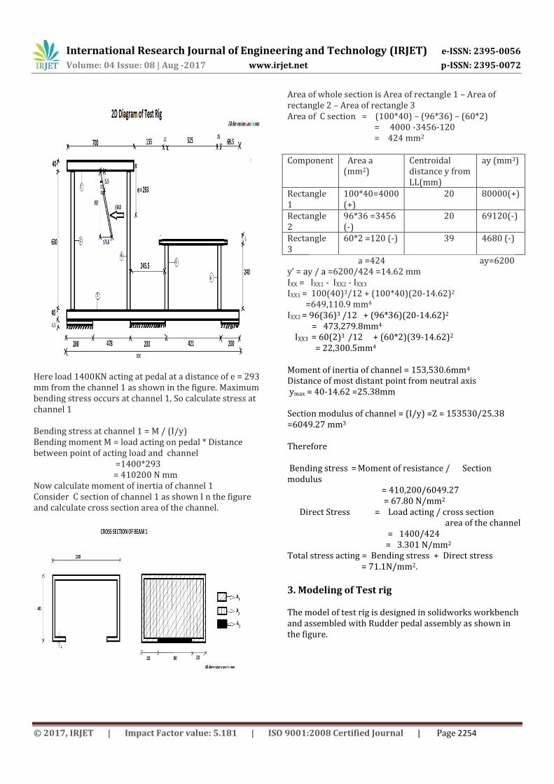
The maximum displacement is 0.28mm if dynamic load of 1400N applied on pedal 1. 5. Results and Discussion 5.1 Static loading
Maximum stress (N/mm2)
Pedal 1
Pedal 2
Load 1050N
50.8 51.7
Load 1400N
67.7 68.9
Maximum displacements (mm)
Pedal
1 Pedal 2
Load 1050N
0.37 0.20
Load 1400N
0.49 0.27
5.2 Dynamic loading(load 1400N)
Maximum stress(N/mm2)
Maximum displacement(mm)
Pedal 1 67.7 0.5
Pedal 2 68.9 0.28
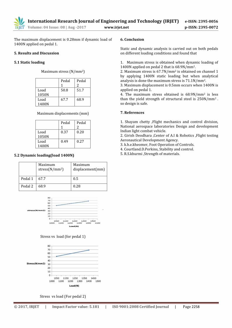
Stress vs load (for pedal 1)
Stress vs load (For pedal 2)
6. Conclusion Static and dynamic analysis is carried out on both pedals on different loading conditions and found that 1. Maximum stress is obtained when dynamic loading of 1400N applied on pedal 2 that is 68.9N/mm2. 2. Maximum stress is 67.7N/mm2 is obtained on channel 1 by applying 1400N static loading but when analytical analysis is done the maximum stress is 71.1N/mm2. 3. Maximum displacement is 0.5mm occurs when 1400N is applied on pedal 1. 4. The maximum stress obtained is 68.9N/mm2 is less than the yield strength of structural steel is 250N/mm2 . so design is safe. 7. References 1. Shayam chetty ,Flight mechanics and control division, National aerospace laboratories Design and development Indian light combat vehicle. 2. Girish Deodhara ,Center of A.I & Robotics ,Flight testing Aeronautical Development Agency. 3. k.h.e.kheomer, Foot Operation of Controls. 4. Courtland.D.Perkins, Stability and control. 5. R.S.khurmi ,Strength of materials.