Embed Size (px)
Citation preview

1
Amandeep Singh Sasan
Master of Engineering (Electronics)
Flinders University
Supervisor: Dr Amin Mahmoudi
October 2017
Submitted to the School of Computer Science, Engineering, and Mathematics to the
Faculty of Science and Engineering for the degree of Master of Engineering
(Electronics)
Design and Analysis of Single-Sided Line-
Start Axial-Flux Permanent Magnet Motor

2
Abstract
This thesis examines the design and development of axial-flux permanent motor
AFPM for the optimal performance. Two four-pole AFPM designs with same stator
design, radial size and excitation is constructed and tested with different rotor
geometries having distinction of induction rings and enclosing magnet within the
rings. The two designs type-1 and type-2 are analyzed with and without magnets as
synchronous and induction motors for comparative study. Both the designs are
analyzed with rotor having separate ring and cage ring induction structure enclosing
magnets. The starting of axial flux permanent magnet motors is based on induction
principle like that of squirrel cage motor. The transient analysis includes the
comparison using speed, torque, harmonics in current during startup. The designs are
also tested and compared under no load and different load conditions. Steady state
analysis includes comparative analysis of Input and Output power, losses and
efficiency. Magnetic analysis is also performed for comparison which covers flux
densities distribution in geometry and airgap of synchronous motor design types. The
analysis and results could be used for further development in design of axial-flux
motors.

3
Contents
Abstract ...................................................................................................................................... 2
List of Figures ............................................................................................................................ 5
List of Tables ............................................................................................................................. 7
Declaration of Academic Integrity ............................................................................................. 8
Acknowledgement ..................................................................................................................... 8
Chapter 1 Introduction……………………………………………………………… 9
1.1 Background……………………………………………………………….. 10
1.2 Problem statement………………………………………………................ 14
1.3 Objectives…………………………………………………………………. 14
1.4 Methodology………………………………………………………………. 14
1.5 Limitations and scope…………………………………………………….. 15
1.6 Thesis Outline………………….…………………………………………. 16
Chapter 2 Literature Review………………………………………………………. 17
2.1 Line Start Permanent Magnet Motor vs Induction Motor……………….. 18
2.2 Axial Flux Motor vs Radial Flux motor…………………………………. 18
2.3 Single sided geometry of axial flux synchronous motor………………… 19
2.4 Magnetic Material……………………………………………………….. 20
2.5 Gap statement…………………………………………………………… 21
2.6 Contribution……………………………................................................... 22
Chapter 3 Design of Motors……………………………………………………….. 23
3.1 Line Start Permanent Magnet Synchronous Motor……………………... 24
3.2 Axial Flux Motor………………………………………………………...
24
3.3 Motor Design Types……………………………………………………..
24
3.3.1 AFPM Motor Type-1……….………………………………………........
25
3.3.2 AFPM Motor Type-2………….……………………………………........ 25
3.4 Design of Stator Disk……………………………………………………. 27
3.5 Design of Stator Winding……………………………………………….. 28
3.6 Design of Rotor…………………………………………………………. 29
3.7 Permanent Magnet………………………………………………………. 30
3.8 Rotor Induction Rings…………..………………………………………. 31
Chapter 4 Simulation Results and Analysis……………………………………… 33
4.1 Method for Simulation and Analysis……………………………………. 34
4.1.1 Meshing………………………………………………………………….. 34
4
4.1.2 Simulation………………………………………………………………. 36
4.1.3 Analysis...……………………………………………………………….. 37
4.2 Magnetic Analysis……………………………………............................. 38
4.2.1 Magnetic Flux Density………………………………………………….. 39
4.2.2 Air Gap Flux Density…………………………………………………… 41
4.2.3 Magnetic Flux Lines……………………………………………………. 43
4.3 Transient Analysis………………………………………………………. 45
4.3.1 Starting and Synchronization……………………………………………. 45
4.3.2 Transient Torque………………………………………………………… 51
4.3.3 Harmonic Content in Current Waveform………………………………... 59
4.3.4 Current distribution in rotor rings……………………………………….. 64
4.4 Steady-state Analysis……………………………………………………. 68
4.4.1 Induced Voltage…………………………………………………………. 68
4.4.2 Input and Output Power…………………………………………………. 71
4.4.3 Losses……………………………………………………........................ 76
4.4.4 Efficiency……………………………………………………………….. 79
Chapter 5 Conclusion and Future Work………………………………………… 80
5.1 Conclusion……………………………………………………………… 81
5.2 Future Work……………………………………………………………… 83
References
Appendices
Appendix A: Stator Excitation Settings.
Appendix B: Mesh Plots.
Appendix C: Exploded view of quarter of geometry used in simulation
Appendix D: Other geometry designs made, and simulation performed during the
project
5
List of Figures
Fig 1: Comparative geometries of radial and axial flux machine…………………… 12
Fig 2: Slotted and Slot less geometry of axial flux permanent magnet machine…… 19
Fig 3: Exploded view of design Type-1 AFPM motor……………..………………..
………...
25
Fig 4: Exploded view of design Type-2 AFPM motor……………..…………..........
………………………….
27
Fig 5: Stator Core Geometry…...………….………………………….........………… 22
Fig 6: Stator Coil Windings.…………………......……………………..……………. 28
Fig 7: Rotor of AFPM Motor Type-1………………………………….……………... 30
Fig 8: Rotor of AFPM Motor Type-2………………………………………………… 30
Fig 9: Magnets of AFPM Motor Type-1……………….……………………….......... 30
Fig 10: Magnets of AFPM Motor Type-2………………………………………........... 30
Fig 11: Induction rings of rotors………………………………………………………. 32
Fig 12: Mesh settings………………………………………………………………….. 35
Fig 13: Motion setup setting…………………………………………………………... 36
Fig 14: Meshes for parts of motor…………………………………………………….. 37
Fig 15: Analysis setup………………………………………………………………… 38
Fig 16: Flux density of design Type-1 and Type-2 induction motors…………………. 40
Fig 17: Air gap flux density of Type-1 AFPM motor…….…………………………… 41
Fig 18: Air gap flux density of Type-2 AFPM motor…….…………………………… 41
Fig 19: Stator Flux Lines in Type-1 AFPM motor…….……………………………… 42
Fig 20: Stator Flux Lines in Type-2 AFPM motor…….………….………...………… 42
Fig 21: Rotor Flux Lines in Type-1 AFPM motor………….………………………… 42
Fig 22: Rotor Flux Lines in Type-2 AFPM motor……….………….……...………… 43
Fig 23: Speed vs. Time at No-load…………………………………………………............. 47
Fig 24: Speed vs Time at 17Nm load……..……….……..…………………………... 48
Fig 25: Speed vs Time at different load…..………………………………………….. 49
Fig 26: Torque vs Time at No Load..……………………..……………………........... 55
Fig 27: Torque vs Time at 17Nm…………………………………………………….. 58
Fig 28: Winding Current vs Time at No Load……………………………………….. 62
Fig 29: Winding Current vs time at Load ………………………………………….. 63
Fig 30: Current Distribution in rotor rings of Type -1 and Type-2 induction motors..
…………………….
67
6
Fig 31: Induced voltage at No Load………………………………………………….. 70
Fig 32: Input and Output power of AFPM motors at 2Nm load……………………….. 70
Fig 33: Input and Output power of induction motors at No load…………………….. 71
Fig 34: Input and Output power of Type-1 and Type-2 at 17 Nm …….…………..… 75
Fig 35: Losses at No Load……………………………………………………………. 76
Fig 36: Losses of Synchronous Motor Type-1 at 20Nm……………………………… 77
Fig 37: Losses of Synchronous Motor type-2 at 17Nm………………………………. 78
Fig 38: Efficiency plots of AFPM motors at 2Nm…………………………………… 79
Fig 38: Efficiency plots of AFPM motors at 17Nm…………………………………. 79

7
List of Tables
Table 1: Scope of standard IEC 60034-30-1:2014……………………………………. 11
Table 2: Scope of Standard IEC 60034-30-1:2014…………………………................ 12
Table 3: Technology comparison chart of Magnax Axial drives……………………... 13
Table 4: Stator Parameters……………………………………………………………. 27
Table 5: Stator Excitation Specifications…………………………………………….. 28
Table 6: Rotor Parameters……..................................................................................... 30
Table 7: Properties of the permanent magnet………………………………………… 31
Table 8: Properties of Aluminium inductor………………………………………….. 31
Table 9: Performance measures across the motor design…………………………….. 82
8
Declaration of Academic Integrity
'I certify that this thesis does not incorporate without acknowledgment any material
previously submitted for a degree or diploma in any university; and that to the best of my
knowledge and belief, does not contain any material previously published or written by
another person except where due reference is made in the text.'
Amandeep Singh Sasan
Date:
Acknowledgements
I would like to acknowledge my supervisor, Dr. Amin Mahmoudi for guiding me throughout
the project and putting all the time and efforts during the time course.

9
Chapter 1
Introduction

10
1.1 Background
Induction Motors
Energy generation in future needs to finds an alternative for saving energy which is
generated on the cost of environmental exploitation. One of the way to optimally use this
energy is by optimizing the design of electric motors to achieve for more higher efficiency.
Highly efficient induction motors are widely used in industrial applications in fact among
all motor applications. Despite the fact more efficient motors are gradually grabbing focus
of the developers.
The standard IEC 60034-30-1 published on March 2014 which replaces the standard IEC
60034-30:2008 by including fourth efficiency level for the classification. The standard has
been appended with 8 pole motors and inclusion of extended power range. The updated
efficiency classes for IEC 60034-30-1 is defined below where IE stands for International
efficiency.
• IE1 (Standard Efficiency)
• IE2 (High Efficiency)
• IE3 (Premium Efficiency)
• IE4 (Super Premium Efficiency)
In the European Union, wide ranging legislation has been ratified with the objective to
reduce energy usage and in turn 𝐶𝑂2 emissions. EU Regulation 640/2009 and the
supplement 04/2014 involve energy usage and/or the energy efficiency of induction motors
in the industrial environment. In the meantime, this regulation is valid in all countries
belonging to the European Union.
11
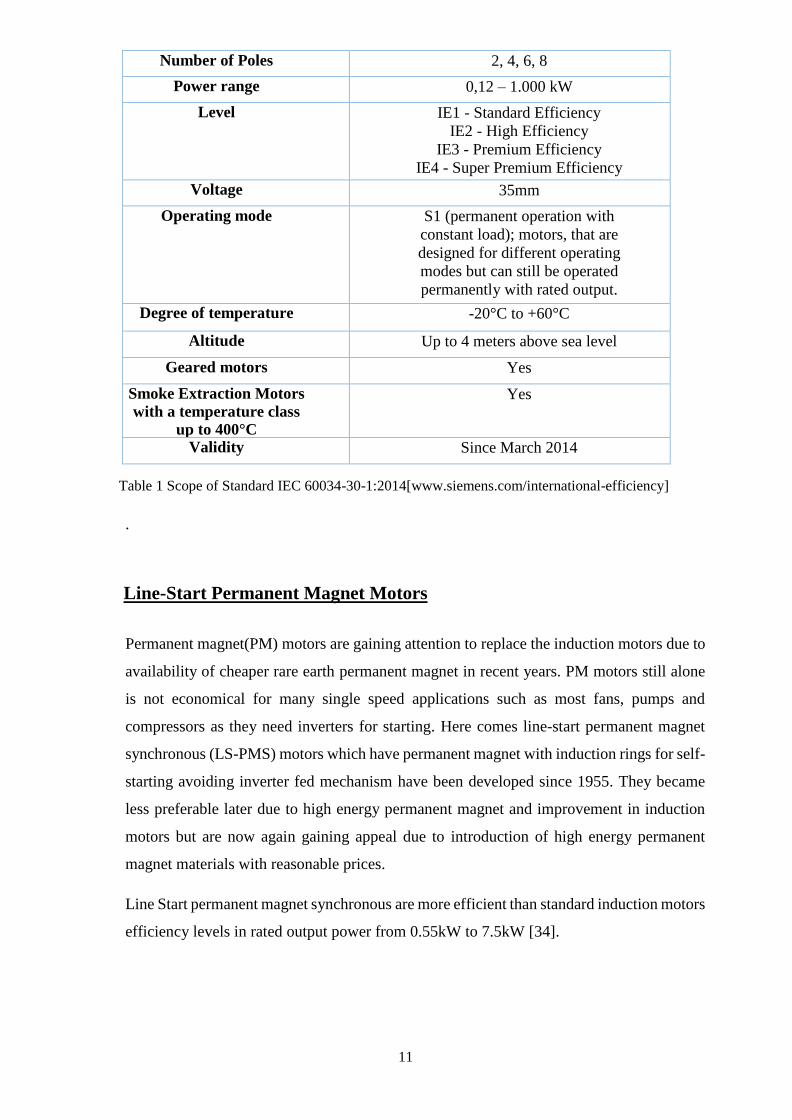
Number of Poles 2, 4, 6, 8
Power range 0,12 – 1.000 kW
Level IE1 - Standard Efficiency
IE2 - High Efficiency
IE3 - Premium Efficiency
IE4 - Super Premium Efficiency
Voltage 35mm
Operating mode S1 (permanent operation with
constant load); motors, that are
designed for different operating
modes but can still be operated
permanently with rated output.
Degree of temperature -20°C to +60°C
Altitude Up to 4 meters above sea level
Geared motors Yes
Smoke Extraction Motors
with a temperature class
up to 400°C
Yes
Validity Since March 2014
Table 1 Scope of Standard IEC 60034-30-1:2014[www.siemens.com/international-efficiency]
.
Line-Start Permanent Magnet Motors
Permanent magnet(PM) motors are gaining attention to replace the induction motors due to
availability of cheaper rare earth permanent magnet in recent years. PM motors still alone
is not economical for many single speed applications such as most fans, pumps and
compressors as they need inverters for starting. Here comes line-start permanent magnet
synchronous (LS-PMS) motors which have permanent magnet with induction rings for self-
starting avoiding inverter fed mechanism have been developed since 1955. They became
less preferable later due to high energy permanent magnet and improvement in induction
motors but are now again gaining appeal due to introduction of high energy permanent
magnet materials with reasonable prices.
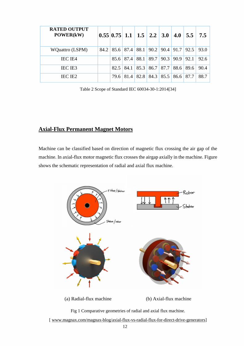
Line Start permanent magnet synchronous are more efficient than standard induction motors
efficiency levels in rated output power from 0.55kW to 7.5kW [34].
12
Table 2 Scope of Standard IEC 60034-30-1:2014[34]
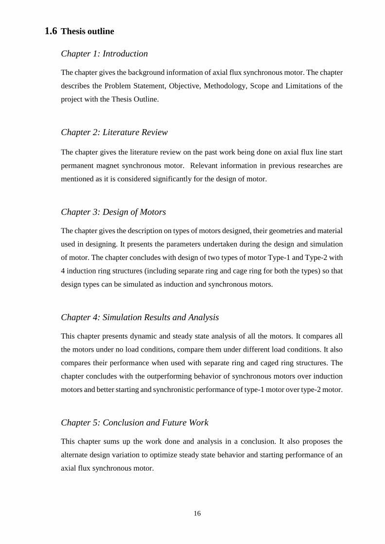
Axial-Flux Permanent Magnet Motors
Machine can be classified based on direction of magnetic flux crossing the air gap of the
machine. In axial-flux motor magnetic flux crosses the airgap axially in the machine. Figure
shows the schematic representation of radial and axial flux machine.
(a) Radial-flux machine (b) Axial-flux machine
Fig 1 Comparative geometries of radial and axial flux machine.
[ www.magnax.com/magnax-blog/axial-flux-vs-radial-flux-for-direct-drive-generators]
RATED OUTPUT
POWER(kW)
0.55
0.75
1.1
1.5
2.2
3.0
4.0
5.5
7.5
WQuattro (LSPM) 84.2 85.6 87.4 88.1 90.2 90.4 91.7 92.5 93.0
IEC IE4 85.6 87.4 88.1 89.7 90.3 90.9 92.1 92.6
IEC IE3 82.5 84.1 85.3 86.7 87.7 88.6 89.6 90.4
IEC IE2 79.6 81.4 82.8 84.3 85.5 86.6 87.7 88.7

13
In axial-flux permanent magnet motors rotor rotates with high-flux magnets and solid
induction rings along disk shape windings on stator. These motors are gaining interest as
major studies have been done in this motor configuration. The magnets are arranged in a
circle enclosed with induction rings facing the stator with space in between to form an axial
air gap.
Axial-flux permanent-magnet (AFPM) machines offers priority features to replace conventional
field winding motor. As it employs permanent magnets losses in field excitation are completed
avoided resulting in high efficiency and output power. Another advantage it offers is requirement
of less core material in construction of such machines which in turn provides high torque to weight
ratio reducing rotor losses significantly.
Recent innovations in axial flux technology low weight and highly efficient direct drive
motors and generators are on the horizon. Table 3 shows the comparison of Axial drive
produced by Magnax corporate of 100kW having rated speed of 60rpm and rated torque of
16kNm with radial flux direct drive and induction motor along with gearbox. The axial drive
is more efficient than typical drives of same output power and rated torque. The axial drive
is far better than commercially available radial and induction drive in terms of weight and
size and are cheaper, reliable and have low maintenance cost.
Table 3 Technology comparison chart of Magnax Axial drives[www.magnax.com-product]
100kW – 60rpm
generator/motor -
16kNm Torque
Induction motor
+ Gearbox
Radial Flux
Direct Drive
Magnax (Axial
Flux) Direct
Drive
Efficiency 80% – 88% 92% – 95% 95% - 97%
Axial Length 1500 mm 700 – 1200 mm 140 mm
Weight 2000-3000 kg 2400 - 5000 kg 850 kg
Investment cost € €€ €
Reliability + +++ +++
Ease of installation - + ++
Maintenance cost Very high Low Low

14
1.2 Problem statement
The axial flux permanent magnet motors today needed to be optimized for industrial
application as it has higher efficiency, high power factor as they are synchronous motors
and addition to that they have other advantages like airgap adjustment because of their air
gap geometry. First of all, it employs permanent magnet which would save lot of power
losses which occurs in winding. Secondly, it uses the axial flux geometry which have
advantage of easily adjustable air gap. Optimized design of such motors would take the
capability of motors to the next level in terms of efficiency and required operating power.
Also, the permanent magnet motor can be useful in constant speed application in industries
and it can replace the small and the medium size of the motor.
1.3 Objectives
1. Create two 3D designs of axial-flux line-start permanent magnet motor with same stator,
same radial size and parameters but different rotor geometries.
2. Simulate and analyze the designs with their magnets removed as well and perform static
and dynamic analysis on both the design types to compare their performances.
3. To compare the both motor design types with separate ring inductor and cage ring
inductor and study the dynamic and steady state response.
1.4 Methodology
The project uses the software Ansys Maxwell 3D to design models of three-phase 4-pole
axial-flux line-start permanent-magnet synchronous motor and simulate geometries for
performance comparison. The project focuses on determining an approach to build single-
sided axial flux line start motor having optimal performance.
Demo models of axial-flux permanent-magnet synchronous motor to give output power of
about 10kW were build and simulated to have prejudgment of parameters to build the motor
with specific requirement to be used in industrial applications. The ideal size, diameter and
width of axial motor is finalized. The first thing was to build the stator which would be used
in all the motors with identical 3-phase source of frequency 50 Hz. Following that rotor

15
with different geometries were tested and designs were developed for AFPM motors. Two
designs were finalized for the comparison of AFPM motors geometries having distinction
of number of induction rings per pole and then motors geometries were also analyzed
without their magnets as induction motor.
Approach to design and development of induction motors prior to synchronous motor was
considered first but adding magnets to induction motor did not give satisfactory results in
analysis so synchronous motor designs were modeled, analyzed and finalized prior to their
analysis with their magnets removed as induction motors. The two designs are analyzed
with separate ring and caged ring rotor. Transient and steady state parameters of the
machines were analyzed and compared and magnetic analysis including distribution of flux
densities, flux lines in design geometry are performed to select the optimal design.
1.5 Limitations and scope
Since the software uses FEM Finite Element Method changing the time step for analysis
affect the dynamic and steady state performances so both the synchronous motors are tested
under same inertia and damping as the geometries are approximately identical in volume.
The results obtained were satisfactory but are limited to simulation analysis and no hardware
model were constructed to validate the analysis.
The motor dynamic and steady state performances could be improved by using hybrid
arrangement axial, radial and circumferential magnetic field of magnets by using
corresponding magnets instead of only axial field magnets. Material used for magnets could
be replaced with NdFeB and aluminum could be replaced with copper for solid rotor cage
in small motors to improve the performance parameters.
16
1.6 Thesis outline
Chapter 1: Introduction
The chapter gives the background information of axial flux synchronous motor. The chapter
describes the Problem Statement, Objective, Methodology, Scope and Limitations of the
project with the Thesis Outline.
Chapter 2: Literature Review
The chapter gives the literature review on the past work being done on axial flux line start
permanent magnet synchronous motor. Relevant information in previous researches are
mentioned as it is considered significantly for the design of motor.
Chapter 3: Design of Motors
The chapter gives the description on types of motors designed, their geometries and material
used in designing. It presents the parameters undertaken during the design and simulation
of motor. The chapter concludes with design of two types of motor Type-1 and Type-2 with
4 induction ring structures (including separate ring and cage ring for both the types) so that
design types can be simulated as induction and synchronous motors.
Chapter 4: Simulation Results and Analysis
This chapter presents dynamic and steady state analysis of all the motors. It compares all
the motors under no load conditions, compare them under different load conditions. It also
compares their performance when used with separate ring and caged ring structures. The
chapter concludes with the outperforming behavior of synchronous motors over induction
motors and better starting and synchronistic performance of type-1 motor over type-2 motor.
Chapter 5: Conclusion and Future Work
This chapter sums up the work done and analysis in a conclusion. It also proposes the
alternate design variation to optimize steady state behavior and starting performance of an
axial flux synchronous motor.

17
Chapter 2
Literature Review

18
2.1 Line Start Permanent Magnet Motor vs Induction Motor
Line Start Permanent Magnet Motor if compared to induction motor are more efficient, has
higher power factor and torque density. Also, it has better thermal properties and are less
sensitive to frequency variations [1]. Starting and Synchronization of such motors depends
on the motor itself and applied load conditions [2].
The permanent magnets provide optimal magnetic flux to minimize the exchanged reactive
power with power supply which in turn provide high power factor corresponding to
minimum line current [4]. The LSPM synchronous motor has two operating modes:
asynchronous mode at starting and transients and synchronous mode at steady state [2]. So,
permanent magnets work under the effect of breaking torque during starting period and
alignment torque during steady state which should be taken into consideration while signing
permanent magnets.
The permanent magnets creating breaking torque during starting is responsible for low
starting torque [5, 6]. The magnetic flux barriers present in the rotor back iron as permanent
magnets are buried below the squirrel cage (for radial flux motor) introduces a breaking
reluctance torque because of rotor saliency, which further lowers the total torque in starting
period. So, the design of LSPM synchronous motor has problem of degrading line starting
performance to be tackled.
2.2 Axial Flux Motor vs Radial Flux motor
Axial flux machines are also gaining appeal as a replacement to radial flux machines as
several researches are carried out in the past few years. The disk shape geometry of this type
of motor offers an advantage of maintaining small air gap in relatively large machines.
Despite of the advantages offered by Axial flux permanent magnet over conventional motor
it was not economically feasible until the rare earth permanent magnets came into use.
There are vast range of papers on this type of machine including more than dozen related to
airgap treatment. AFPM motors have application in electric vehicles which contribute to help in
avoiding environmental pollution.

19
In [12] Parviainen, Niemela, Pyrhonen, and Mantere reported a detailed study comparing
traditional radial flux geometry to the two-slotted stator one rotor axial flux machine,
(AFPM-21). Mechanical constraints were discussed and included in the analysis. Their final
comparison was on cost of the active materials only. Their conclusions were that at 8 poles
the 2 designs were very similar cost, and that at greater than 8 poles the axial flux geometry
was lower cost than the radial flux.
2.3 Single sided geometry of axial flux synchronous motor
Single sided axial flux machine offers some considerable advantages over the conventional
radial flux machine and double sided axial flux machine. Fig 3 shows the slotted and slot
less geometry of single sided axial flux permanent magnet motor [13]. There are certain
developers who developed the axial flux permanent motor such as SAIETTA, MSF
Technologies, EVANS ELECTRIC.
Fig 2 Slotted and Slot less geometry of axial flux permanent magnet machine [13].
20
Studies shows that the single sided axial flux machine has a considerable volumetric
advantage over the traditional radial flux machine. The inside volume of a traditional radial
flux rotor, or indeed the stator on an outside rotor radial flux machine, is not used
electromagnetically. There is a very definite volumetric advantage to axial flux machines at
reasonably high pole counts. The inside volume of a traditional radial flux rotor, or indeed
the stator on an outside rotor radial flux machine, is not used electromagnetically. Ingenious
solutions for “slinky” style wound stators for outside rotor machines, and spiders to support
a rotor structure, will not save volume, but will save active material, and hence both active
and passive mass [8]. Also in slot less stator magnetic force is exerted on iron rather than
on copper winding resulting in twisting of the structure [9].
In [16] a preliminary design of double slotted axial flux permanent magnet AFPM motor
was designed for electric vehicle direct drive. The design was tested with 6 rotor poles for
high torque density and stable rotation. The designed motor is capable to produce 10kW
power and the maximum amplitude of the sinusoidal back EMF was 105V at 1000rpm rated
speed.
In [7] Sitapati and Krishnan focuses on comparison of radial and axial flux geometries. They
employed 5 geometries a slotted single sided, an unslotted single sided, (both AFPM-11),
two stators and one rotor (the AFPM-21), and a variant on the TORUS NS machine in which
the single stator had no iron, using just an airgap winding. They tested their geometries
with 5 different power levels and concluded that for the same torque rating axial flux
machine would have less volume in comparison to radial flux and that it is advantageous to
have slots in stator and rotor of axial flux machine as it reduces the copper and magnetic
material for coils and magnets to work effectively.
On the downside in [10,11] single stator single rotor geometry of axial flux permanent
magnet AFPM machine have unbalanced axial force between their stator and rotor which
consequently requires thick rotor disk and complex bearing arrangement if compared to
double sided geometry.

21
2.4 Startup of Line Start and Axial Flux Permanent Magnet Motor
In [17], axial flux permanent magnet motors having solid rotor and composite rotor designs
were compared. Results showed that the composite rotor significantly improving both
starting torque and synchronization capability over solid rotor. The thin layer of copper on
the rotor-ring surface is employed to increase conductivity of the material for more current
circulation on the rotor-ring surface during start-up to improve dynamic response,
synchronization time and drive heavier loads.
In 2015, 1.1 kW three phase 4 poles hybrid LSPMSM for fans systems is analyzed using
Rmxprt and Maxwell 2D simulation. The effect of the magnet size on breaking torque is
examined in Line Start permanent magnet synchronous motor. It is concluded that breaking
torque which is the sum of cage torque and breaking torque is proportional to the magnet
size directly.
2.5 Gap Statement
The literature review includes the studies on line-start permanent magnet motors and axial
motors and points out advantages of single sided geometry of axial-flux permanent magnet
motors. Also, there is appreciable work done on improving the synchronization time of the
rotor while considering the cost factor as well but the studies demand much more work as
there is a lot of scope to test and improve other parameters to improve the dynamic and
steady state response. This project compares the effect of number of rings under single pole
on the performance of motor. Two four pole axial-flux permanent magnet synchronous
motors are designed with similar stator geometry and analyzed with rotor having distinction
of number of rings and magnets enclosed in them. The project also shows the comparison
with their performance as induction motor when analyzed without magnets.

22
2.6 Contribution
The project aims to develop optimized design of highly efficient axial flux permanent
magnet motor. Two designs constructed are chosen for the comparative analysis to
understand role of parameters considered during the design for such kind of motor. The two
designs are analyzed with and without the magnets to compare their performance in terms
of efficiency, output power, maximum load bearable. The analysis is performed to compare
how the dynamic and steady state behavior get effected with change in induction ring
geometry and magnets and compare the performances on the similar grounds without
magnets as induction motors.
23
Chapter 3
Design of Motors

24
3.1 Line Start Permanent Magnet Synchronous Motor
Line Start Permanent Magnet Motor if compared to induction motor are more efficient, has
higher power factor and torque density. Also, it has better thermal properties and are less
sensitive to frequency variations [1]. Starting and Synchronization of such motors depends
on the motor itself and applied load conditions [2].
3.2 Axial Flux Motor
Axial-flux motor are the motors with different magnetic flux path compared to conventional
radial motor. The magnetic flux flows parallel to axial of the motor. Axial-flux permanent-
magnet (AFPM) motors over conventional radial-flux permanent-magnet (RFPM) motors
are more efficient, better torque-to-weight ratio, more balanced rotor-stator attractive forces,
and better heat-removal [3,4]. Also, axial-flux motor air-gaps are planar and adjustable [5].
3.3 Motor Design Types
Two axial flux line-start permanent magnet motors having same stator geometry are
designed for this project. The synchronous motors are then analyzed without magnets as
induction motors. So, there are 8 different types of motors under analysis in the project. All
the four motors have same stator configuration. The motor differs in induction rings
geometry and magnets embedded on rotor.
Two design types are designed and operated with separated and cage rings with and without
magnet. The stator slot wounded with three phase supply (shown in color green, orange and
blue in Figure 4 and Figure 5) of four poles produces rotating magnetic field. Magnets
enclosed in induction rings are combined with rotor will start as induction motor under the
effect of this rotating magnetic field. On achieving synchronous speed magnets of the rotor
get locked with rotating magnetic field and hence move with synchronous speed.

25
3.3.1 AFPM Motor Type-1
The design type has eight rings and eight magnets embedded on rotor disk with two similar
poles together so that rotor poles would have resultant four poles to interact as it is a four-
pole motor. Figure show exploded view of the axial flux permanent magnet motor type-1.
Fig 3 Exploded view of design Type-1 AFPM motor.
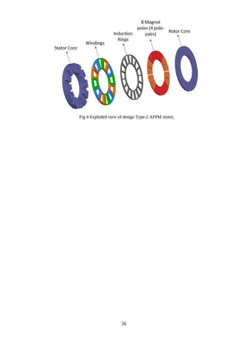
3.3.2 AFPM Type-2
The design type-2 of axial-flux permanent magnet motor is different from type-1 in a way
that it has sixteen rings with magnets embedded on the rotor disk. For magnetic locking
between stator and rotor poles of pole motor four similar magnets are placed consecutively.
26
Fig 4 Exploded view of design Type-2 AFPM motor.
27
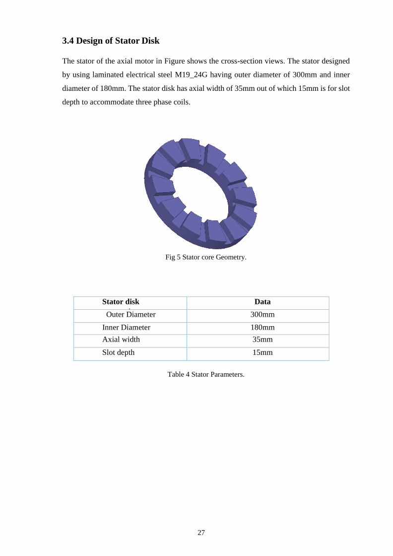
3.4 Design of Stator Disk
The stator of the axial motor in Figure shows the cross-section views. The stator designed
by using laminated electrical steel M19_24G having outer diameter of 300mm and inner
diameter of 180mm. The stator disk has axial width of 35mm out of which 15mm is for slot
depth to accommodate three phase coils.
Fig 5 Stator core Geometry.
Stator disk
parameters
Data
Outer Diameter 300mm
Inner Diameter 180mm
Axial width 35mm
Slot depth 15mm
Table 4 Stator Parameters.

28
3.5 Design of Stator Windings
The 3 phase windings constructed using copper material having axial width of 15mm. The
windings are excited through 310V line to line supply of 50Hz. The table gives the specification
of parameters employed for construction and excitation.
Fig 6 Stator Coil Windings.
Winding parameters Data
Number of conductors per coil
75
Resistance 0.2ohm
Inductance 0.3mH
Phase A 240*sin(2*pi*50*time+2*pi/3) V
Phase B 240*sin(2*pi*50*time) V
Phase C 240*sin(2*pi*50*time-2*pi/3) V Frequency 50Hz
Table 5 Stator Excitation Specifications.

29
3.6 Design of Rotor
The rotor disk of the motors was designed with M19_24G laminated steel having outer and
inner diameter similar to that of the stator. The axial flux permanent magnet motor uses
aluminum induction rings for initial startup of the motor. The magnets are placed inside the
rings for the magnetic locking between stator and rotor magnetic poles. Two rotors having
distinction of number of rings and magnets for comparative analysis. Figure illustrate the
side view of rotors of both the motor types.
Fig 7 Rotor of AFPM Motor Type-1.
Fig 8 Rotor of AFPM Motor Type-2

30
Rotors parameters Data
Outer Diameter 300mm
Inner Diameter 180mm
Width of Rotor Disk 15mm
Axial Width of Aluminium Rings 10mm
Thickness of Aluminium Rings 2mm
Table 6 Rotor Parameters
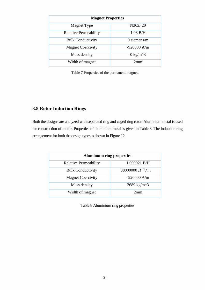
3.7 Permanent magnet
The material N36Z_20 with specifications in Table is added to the library and used in the
simulations. Rare earth permanent magnets like Samarmium-Cobalt or Neodymium could
be used with hardware to make motors more economical on the sake of performance to
some extent. Figure 10 shows the half view of the magnets employed in two axial flux
machine designs modeled for analyses. The direction of arrows shows the direction of
magnetic field lines which distinguishes north pole of the magnet with south pole.
Fig 9 Magnets of AFPM Motor Type-1.
Fig 10 Magnets of AFPM Motor Type-2.
31
Table 7 Properties of the permanent magnet.
3.8 Rotor Induction Rings
Both the designs are analyzed with separated ring and caged ring rotor. Aluminium metal is used
for construction of motor. Properties of aluminium metal is given in Table 8. The induction ring
arrangement for both the design types is shown in Figure 12.
Table 8 Aluminium ring properties
Magnet Properties
Magnet Type N36Z_20
Relative Permeability 1.03 B/H
Bulk Conductivity 0 siemens/m
Magnet Coercivity -920000 A/m
Mass density 0 kg/m^3
Width of magnet 2mm
Alumimum ring properties
Relative Permeability 1.000021 B/H
Bulk Conductivity 38000000 𝛺−1 𝑚⁄
Magnet Coercivity -920000 A/m
Mass density 2689 kg/m^3
Width of magnet 2mm

32
(a) Type-1 Separated Ring
Inductors
(c) Type-1 Caged Ring inductor
(b) Type-2 Separated Ring
Inductors
(d) Type-2 Caged Ring Inductor
Fig 11 Induction rings of rotors

33
Chapter 4
Simulations Results and Analysis

34
4.1 Method for Simulation and Analysis
The software Ansys Maxwell having approach based on Finite Element Analysis is used for
the design of the three motors. The axial flux permanent magnet motors designed were
simulated with and without the magnets. Magneto static and transient Analysis were
performed on one-fourth of the motor using the symmetrical analysis feature (employing
Master and Slave Boundary conditions) of the software. The simulations were performed
with timestep of 0.5ms.
4.1.1 Meshing
Using mesh operations, meshes are defined for transient simulation. The meshes are defined
in such a way that mesh density fulfil the performance requirements and aid in better
analysis. Meshes for different motor parts are defined accordingly and shown in the
following figures.

35
Fig.12 Mesh settings

36
4.1.2 Simulation
The designed motors are assigned with motion setup for simulating the motors. The
parameters like inertia, damping and load torque are assigned for functioning of the motor.
All the motors are assigned with inertia of 0.01 𝐾𝑔𝑚2. However, damping for induction
motors are set to 0 N-m-sec/rad while damping for synchronous motors are set to 0.001 N-
m-sec/rad. The following figure shows settings for Motion Setup of Motors.
Fig 13 Motion Setup Settings
37
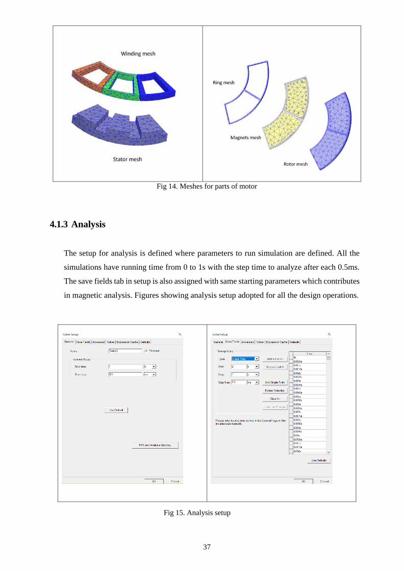
Fig 14. Meshes for parts of motor
4.1.3 Analysis
The setup for analysis is defined where parameters to run simulation are defined. All the
simulations have running time from 0 to 1s with the step time to analyze after each 0.5ms.
The save fields tab in setup is also assigned with same starting parameters which contributes
in magnetic analysis. Figures showing analysis setup adopted for all the design operations.
Fig 15. Analysis setup

38
On completion of simulation report are created for dynamic analysis. The motion setup
created keep track of transient parameters such as moving speed, moving torque, winding
current. Output variables is also defined to obtain performance of input/output power and
efficiency.
4.2 Magnetic Analysis Magnetic Analysis for getting magnetic field intensity and magnetic flux lines around the
machine were performed. The process involves computation of magnetic field in and around the
machine at specific time intervals. Magneto static analysis could be used in applications such
as, motors and generators, relays, sensors and solenoids.
4.2.1 Magnetic Flux Density
The magnetic flux density for the performance evaluation of the machine is calculated in
several ways. analytical (Lee, 1992; Furlani, 1994; Zhilichev, 1998; Qamaruzzaman and
Dahono, 2008; Loureiro et al, 2008; Chan et al., 2009; Kano et al., 2010), quasi 3D (Azzouzi
et al., 2005; Kurronen and Pyrhonen, 2007; Marignetti et al., 2010), finite element method
(FEM) (Bumby et al., 2004; Rong-Jie and Kamper, 2004; Upadhyay and Rajagopal, 2006;
Chan et al., 2010), and method of images (Sang-Ho et al., 2006). FEM is more accurate than
analytical method is, and can be used in complicated machine constructions. Finite element
analysis (FEA) has long computation time, and a different model (including re-meshing) is
needed when machine geometry changes. Magnetic flux density in the motor represent
intensity of magnetic field forces throughout the geometry or on their surface.
High magnetic flux density indicates high magnitude of flux linkage through the coil. The
induced emf (electromotive force) due to excited stator coil is directly proportional to
number of turns and flux linkage and can be given by equation.
𝐼𝑛𝑑𝑢𝑐𝑒𝑑 𝑒. 𝑚. 𝑓 = 𝑁𝑑𝜙
𝑑𝑡
Where N is number of turns and 𝟇 is the flux in the cross section of coil which is changing
with time due to rotational motion of overall flux due to three phase excitation in the
geometry.
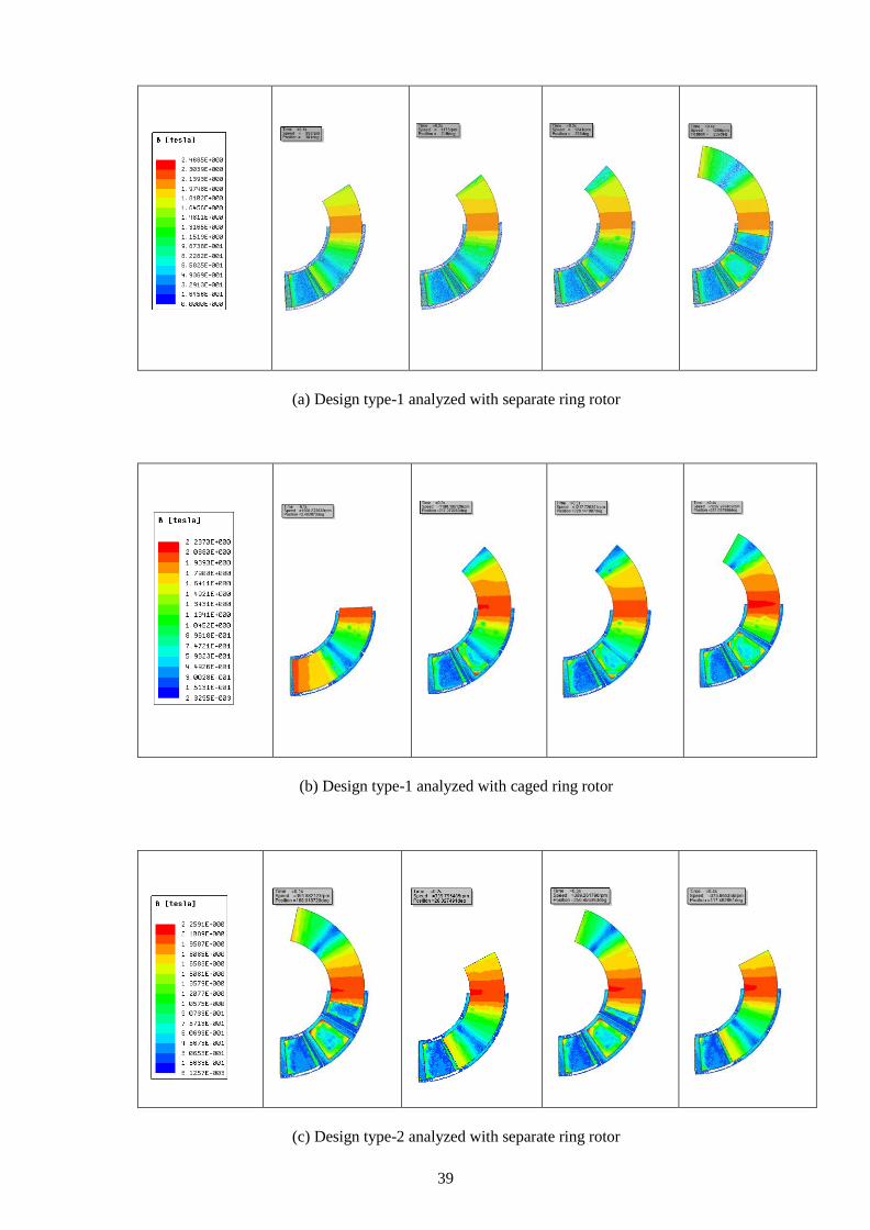
39
(a) Design type-1 analyzed with separate ring rotor
(b) Design type-1 analyzed with caged ring rotor
(c) Design type-2 analyzed with separate ring rotor

40
(d) Design type-2 analyzed with caged ring rotor
Fig 16 Flux density of Type-1 and Type-2 induction motors.
Fig 13 shows that the flux densities is better and higher in type-1 design when compared to
design type-2. Also, when operated and analyzed with caged ring rotor rather than separate
ring rotor improves the flux densities in the motor field which is due to better current
distribution short circuited ring structure.
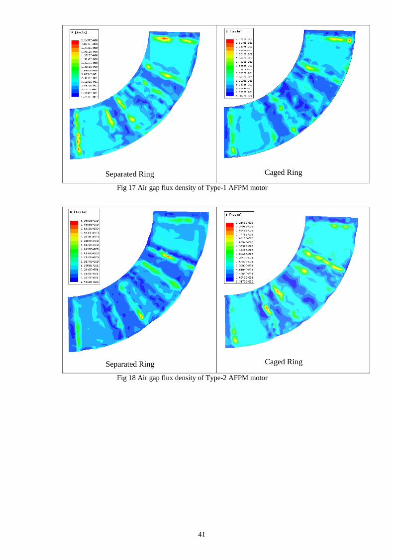
4.2.2 Air Gap Flux Density
The magnetic flux density in the airgap between the stator and rotor is also analyzed for all
the four geometries at no load. From the figures airgap flux density can be seen lower in the
axial regions of coils where the flux is limited by steel and shows a steep rise near the coil
winding. The windings in stator is deep but still very close to stator and because it is axial
flux machine the winding field is exposed to airgap without any laminated steel in the
circumference where it is wounded which makes magnetic flux higher in these regions. This
maximum magnitude could be reduced by employing closed slots in stator.
41
Separated Ring
Caged Ring
Fig 17 Air gap flux density of Type-1 AFPM motor
Separated Ring
Caged Ring
Fig 18 Air gap flux density of Type-2 AFPM motor

42
4.2.3 Magnetic Flux Lines
Magnetic Flux lines illustrates magnetic vector potential in the machine. Magnetic flux
lines are compared for all the four motors. The rainbow color scale shows the vector
potential in Wb/m. Flux lines analysis helps in understanding the locking mechanism of
stator and rotor magnetic poles which could be helpful in designing motors with high
performances.
Fig 19 Stator Flux Lines in Type-1 AFPM motor.
Fig 20 Stator Flux Lines in Type-2 AFPM motor.
Fig 21 Rotor Flux Lines in Type-1 AFPM motor.

43
Fig 22 Rotor Flux Lines in Type-2 synchronous motor.
Magnetic flux vector representation of all four designed motors confirms the correct
working of motors and helps one to understand the interaction between stator and rotor
magnetic pole. The magneto static analysis of permanent magnet and induction motors
designed were observed to identify behavior of travel path of flux lines throughout the
motor and their interaction with each other.
For a continuous charge distribution in motion equation for Lorentz force would be
𝑑𝐹 = 𝑑𝑞(𝐸 + 𝑣 × 𝐵)
where dF is the force on charge dq. From this equation force density can be deduced as
𝑓 = 𝜌(𝐸 + 𝑣 × 𝐵)
𝑓 = 𝜌𝐸 + 𝐽 × 𝐵
where 𝜌 is the charge density (charge per unit volume) and J is the current density. The
total force in the volume integral over the charge distribution is
𝐹 = ∭ (𝜌𝐸 + 𝐽 × 𝐵)𝑑𝑉

44
4.3 Transient analysis
The transient performance of the constructed four designs are examined for comparative
analysis to understand parameters adjustment while making axial motor having optimal
performance. Starting performance at no load are compared based on transient speed
performance, transient torque and transient current. The performances are also analyzed
at the load near to maximum bearable load for starting of the motor. All the simulations
were carried out for 1 second with the time step of 0.5 milliseconds.
4.3.1 Starting and Synchronization
The starting performance of the constructed four designs are examined for comparative
analysis. In this part of the chapter, the focus is on the starting of the motor and the time
to reach the full rated speed is examined. For the starting analysis of the motor the plot
for the Speed Vs. time is considered where input supply voltage is 240V for all the
motors except Type-2 synchronous motor where supply voltage is 400V as type 2
separate ring synchronous motor was not starting at 240V. The moment of inertia of all
the motors were set to 0.01𝑘𝑔𝑚2.The simulation was carried out for 1second and the
step time was set to 0.5ms. While testing the motor for the starting performance it is
tested for two different loading condition such as no-load and full load. The results for
no-load and full-load are illustrated in fig 26 and fig 27 respectively.
(a) Type-1 AFPM motor having separate ring rotor at No-load
supplied with 240V

45
(b) Type-1 AFPM motor having caged ring rotor at No-load
supplied with 240V
(c) Type-2 AFPM motor having separate ring rotor at No-load
supplied with 400V
(d) Type-2 AFPM motor having caged ring rotor at No-load
supplied with 400V

46
(e) Type-1 Induction motor having separate ring rotor at No-load
supplied with 240V
(f) Type-1 Induction motor having caged ring rotor at No-load
supplied with 240V
(g) Type-2 Induction motor having separated ring rotor at No-load
supplied with 240V

47
(h) Type-2 Induction motor having caged ring rotor at No-load
supplied with 240V
Fig 23 Speed Vs. Time at No-load.
(a) Type-1 AFPM motor having separated ring rotor at 17Nm
supplied with 400V
(b) Type-1 AFPM motor having caged ring rotor at 17Nm
supplied with 400V
48
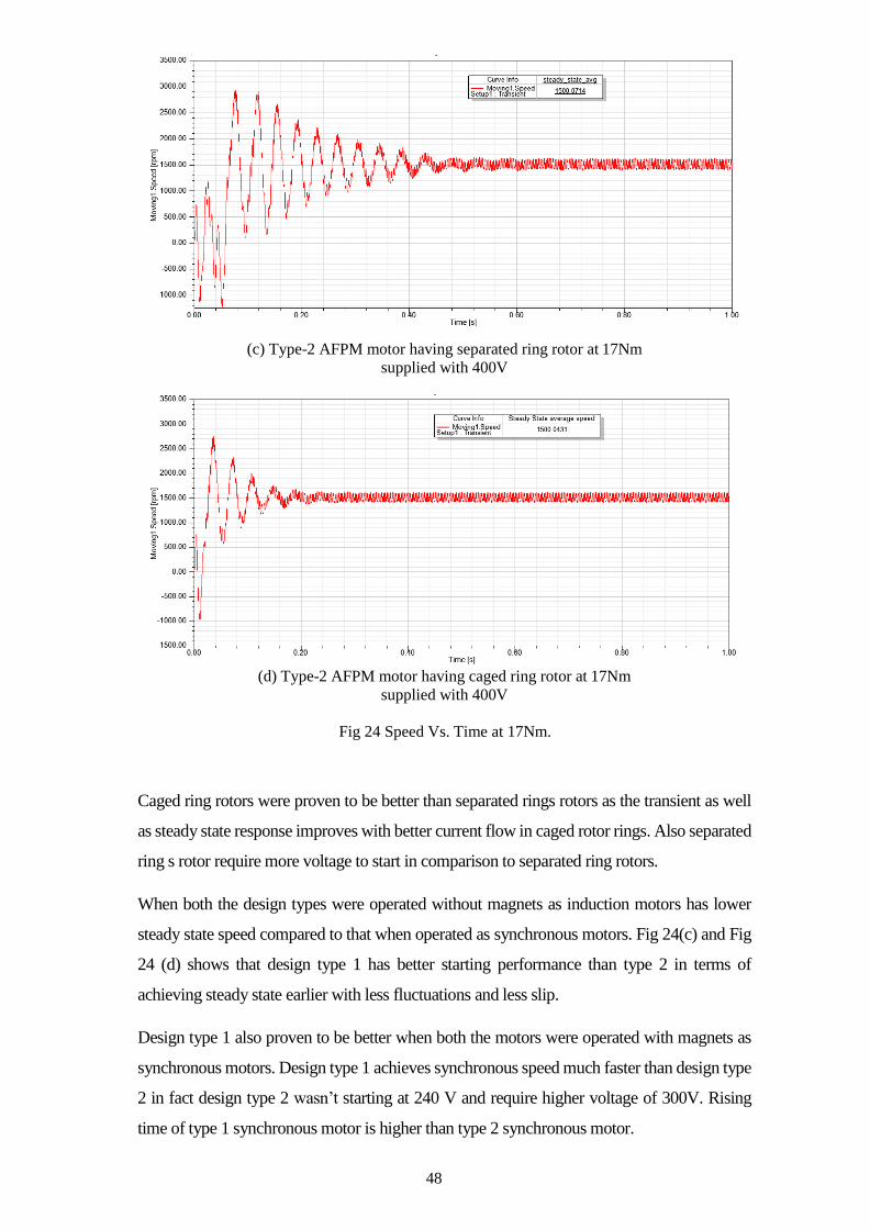
(c) Type-2 AFPM motor having separated ring rotor at 17Nm
supplied with 400V
(d) Type-2 AFPM motor having caged ring rotor at 17Nm
supplied with 400V
Fig 24 Speed Vs. Time at 17Nm.
Caged ring rotors were proven to be better than separated rings rotors as the transient as well
as steady state response improves with better current flow in caged rotor rings. Also separated
ring s rotor require more voltage to start in comparison to separated ring rotors.
When both the design types were operated without magnets as induction motors has lower
steady state speed compared to that when operated as synchronous motors. Fig 24(c) and Fig
24 (d) shows that design type 1 has better starting performance than type 2 in terms of
achieving steady state earlier with less fluctuations and less slip.
Design type 1 also proven to be better when both the motors were operated with magnets as
synchronous motors. Design type 1 achieves synchronous speed much faster than design type
2 in fact design type 2 wasn’t starting at 240 V and require higher voltage of 300V. Rising
time of type 1 synchronous motor is higher than type 2 synchronous motor.

49
From the speed plots, it is observed that design type-1 has better performance than design
type-2. The synchronous motor design and induction motor design of type-1 are better than
their counterparts. The induction motor design however has less overshoot and less settling
time.
The speed vs time graphs of axial flux permanent magnet motors under different load
conditions in Figure illustrates the distinction between the performances of motors.
(a) Type-1 AFPM Motor having separated ring rotor
supplied with 310V
(b) Type-2 AFPM Motor having separated ring rotor
supplied with 310V
Fig 25 Speed Vs Time at different load
-1500
-1000
-500
0
500
1000
1500
2000
2500
3000
3500
0 0.1 0.2 0.3 0.4 0.5 0.6 0.7 0.8 0.9 1
Spee
d(r
pm
)
Time(s)
Speed vs Time
0 Nm 7 Nm 20 Nm 21 Nm
-2000
-1500
-1000
-500
0
500
1000
1500
2000
2500
3000
0 0.1 0.2 0.3 0.4 0.5 0.6 0.7 0.8 0.9 1
Spee
d(r
pm
)
Time(s)
Speed vs Time
0 Nm 7 Nm 17 Nm 18 Nm
50
From the Fig 25 it was founded that the design type-1 of axial flux permanent magnet
motor can bear maximum load of about 20Nm as it is not starting under the load of
21Nm while the design type-2 of axial flux permanent magnet motor have less maximum
load driving capability of about 17Nm and is not starting under 18Nm.
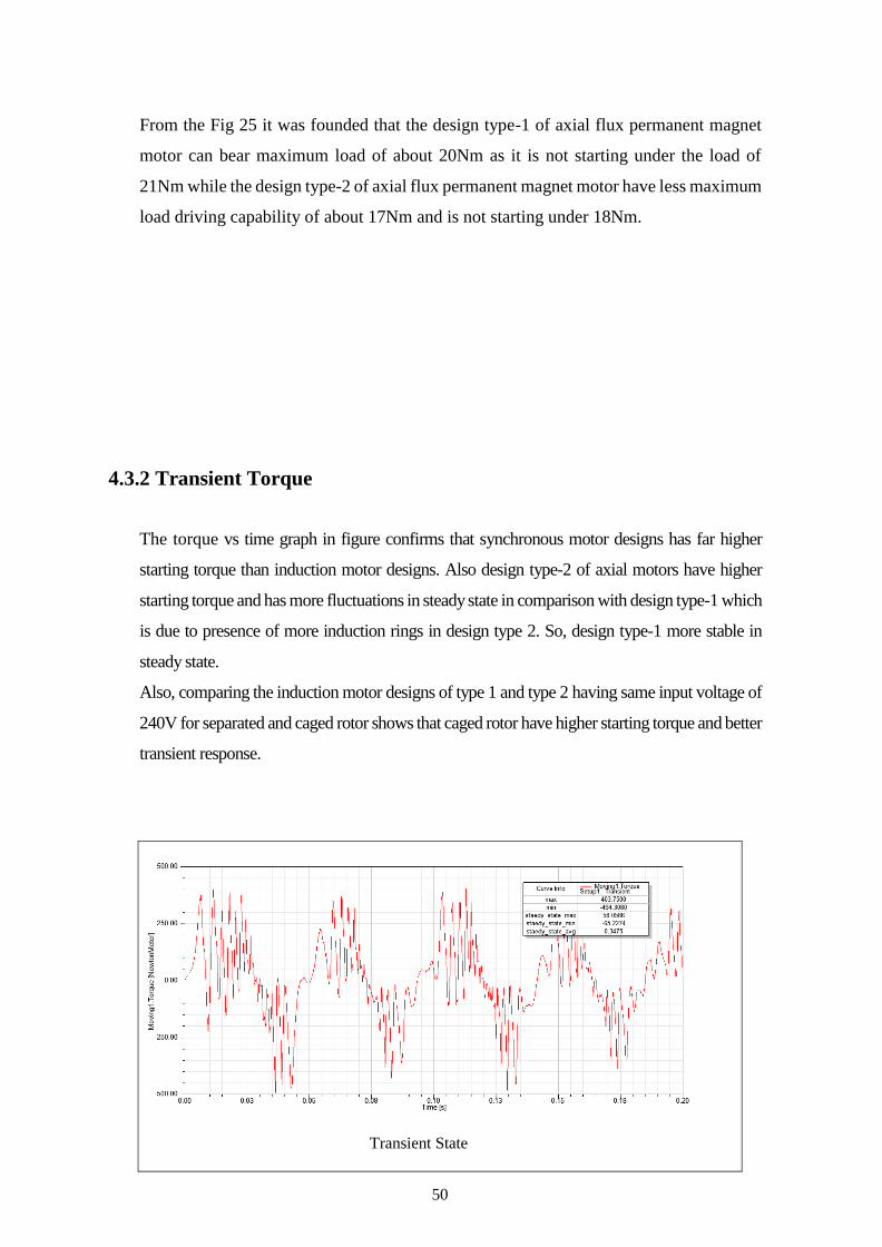
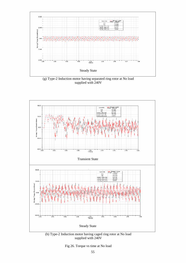
4.3.2 Transient Torque
The torque vs time graph in figure confirms that synchronous motor designs has far higher
starting torque than induction motor designs. Also design type-2 of axial motors have higher
starting torque and has more fluctuations in steady state in comparison with design type-1 which
is due to presence of more induction rings in design type 2. So, design type-1 more stable in
steady state.
Also, comparing the induction motor designs of type 1 and type 2 having same input voltage of
240V for separated and caged rotor shows that caged rotor have higher starting torque and better
transient response.
Transient State

51
Steady State
(a) Type-1 AFPM motor having separated ring rotor at No load
supplied with 240V
Transient State
Steady State
(b) Type-1 AFPM motor having caged ring rotor at No load
supplied with 240V

52
Transient State
Steady State
(c) Type-2 AFPM motor having separated ring rotor at No load
supplied with 400V
Transient State

53
Steady State
(d) Type-2 AFPM motor having caged ring rotor at No load
supplied with 400V
Transient State
Steady State
(e) Type-1 Induction motor having separated ring rotor at No load
supplied with 240V

54
Transient State
Steady State
(f) Type-1 Induction motor having caged ring rotor at No load
supplied with 240V
Transient State
55
Steady State
(g) Type-2 Induction motor having separated ring rotor at No load
supplied with 240V
Transient State
Steady State
(h) Type-2 Induction motor having caged ring rotor at No load
supplied with 240V
Fig 26. Torque vs time at No load
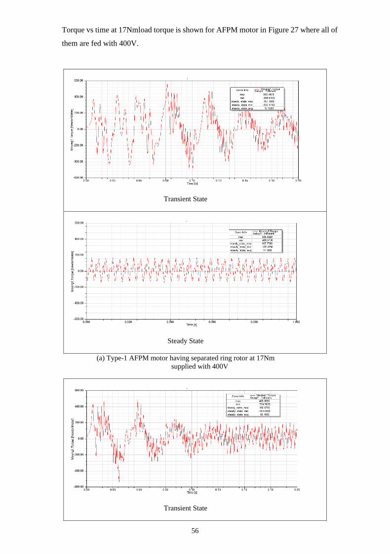
56
Torque vs time at 17Nmload torque is shown for AFPM motor in Figure 27 where all of
them are fed with 400V.
Transient State
Steady State
(a) Type-1 AFPM motor having separated ring rotor at 17Nm
supplied with 400V
Transient State

57
Steady State
(b) Type-1 AFPM motor having caged ring rotor at 17Nm
supplied with 400V
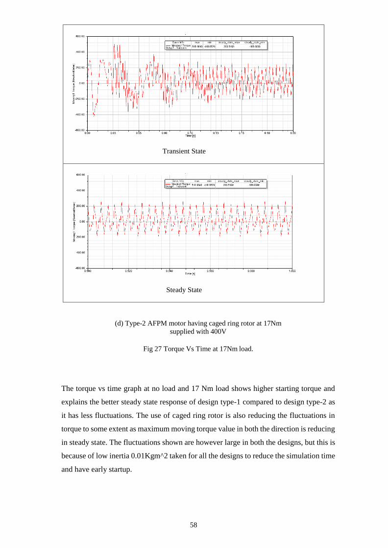
Transient State
Steady State
(c) Type-2 AFPM motor having separated ring rotor at 17Nm
supplied with 400V
58
Transient State
Steady State
(d) Type-2 AFPM motor having caged ring rotor at 17Nm
supplied with 400V
Fig 27 Torque Vs Time at 17Nm load.
The torque vs time graph at no load and 17 Nm load shows higher starting torque and
explains the better steady state response of design type-1 compared to design type-2 as
it has less fluctuations. The use of caged ring rotor is also reducing the fluctuations in
torque to some extent as maximum moving torque value in both the direction is reducing
in steady state. The fluctuations shown are however large in both the designs, but this is
because of low inertia 0.01Kgm^2 taken for all the designs to reduce the simulation time
and have early startup.

59
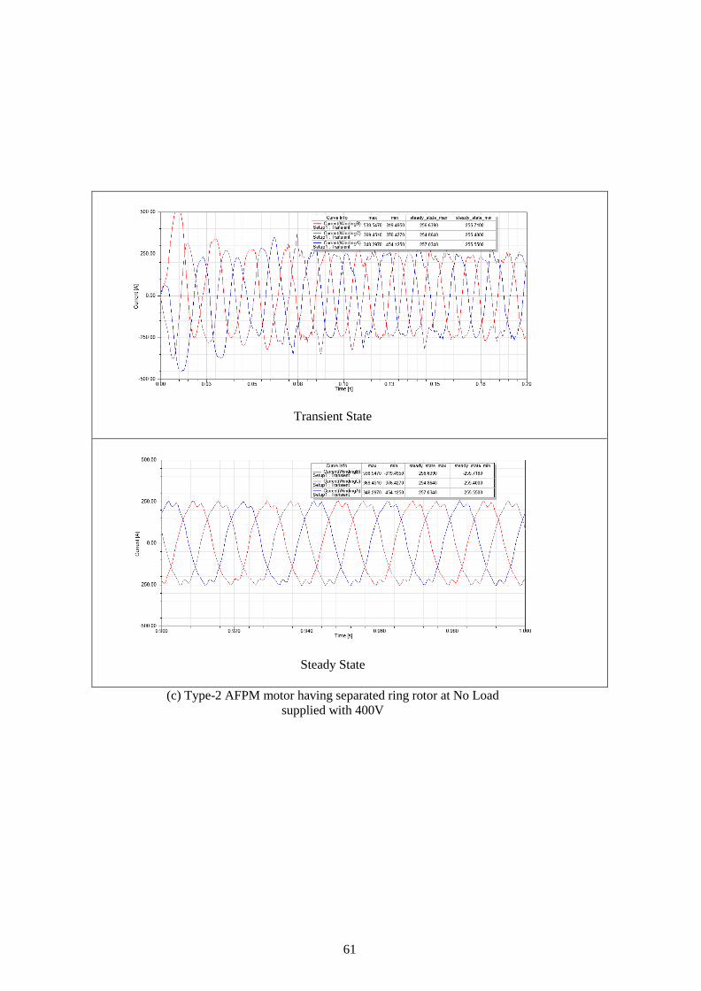
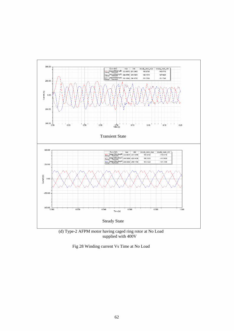
4.3.3 Harmonic Content in Current Waveform
The transients for winding current in all the four designs under no load condition in Fig
27 are presented. It was founded that design type-1 have good transient response as it
take less time to achieve steady state. The winding currents are verified to be sinusoidal
or balanced in terms of phase shift and magnitude for the appropriate working and
performance of the designs.
Transient State
Steady State
(a) Type-1 AFPM motor having separated ring rotor at No Load
supplied with 240V

60
Transient State
Steady State
(b) Type-1 AFPM motor having caged ring rotor at No Load
supplied with 240V
61
Transient State
Steady State
(c) Type-2 AFPM motor having separated ring rotor at No Load
supplied with 400V
62
Transient State
Steady State
(d) Type-2 AFPM motor having caged ring rotor at No Load
supplied with 400V
Fig 28 Winding current Vs Time at No Load

63
Winding Current in Type-1 AFPM motor having separated ring rotor at 20Nm
Winding Current in Type-2 AFPM motor having separated ring rotor at 17Nm
Fig 29 Winding Current at Load
From the current waveforms it is clarified that design type-1 have lower harmonic
content than design type-2 during startup. Also, the harmonics improves when design
are operated with caged ring rotor instead of separated ring rotor. The harmonic content
is far high under load condition and comparatively design type-2 have higher starting
harmonics when compared to design type-1 under load of 17Nm condition with larger
transient state.
64
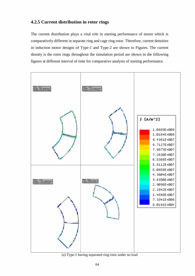
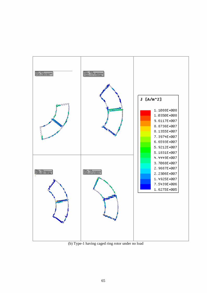
4.2.5 Current distribution in rotor rings
The current distribution plays a vital role in starting performance of motor which is
comparatively different in separate ring and cage ring rotor. Therefore, current densities
in induction motor designs of Type-1 and Type-2 are shown in Figures. The current
density is the rotor rings throughout the simulation period are shown in the following
figures at different interval of time for comparative analysis of starting performance.
(a) Type-1 having separated ring rotor under no load
65
(b) Type-1 having caged ring rotor under no load

66
(b) Type-2 having separated ring rotor under no load

67
(b) Type-2 having caged ring rotor under no load
Fig. 30 Current distribution in rotor rings of Type-1 and Type-2 induction motor
It can be stated from the current density vector figures that the current distribution in
cage ring rotor improves the current density magnitude and hence higher starting
current in rotor ring which improvs the transient response of motor. Design Type -1
have higher current density if compared to design Type-2 which confirms the that

68
design Type-1 have better transient response than type-1.
4.4 Steady State Analysis
Steady State analysis is performed by analyzing the quantities such as winding currents,
input and output power, steady state losses and efficiency. For steady state analysis range
of time period is kept between 0.6s to 1s.
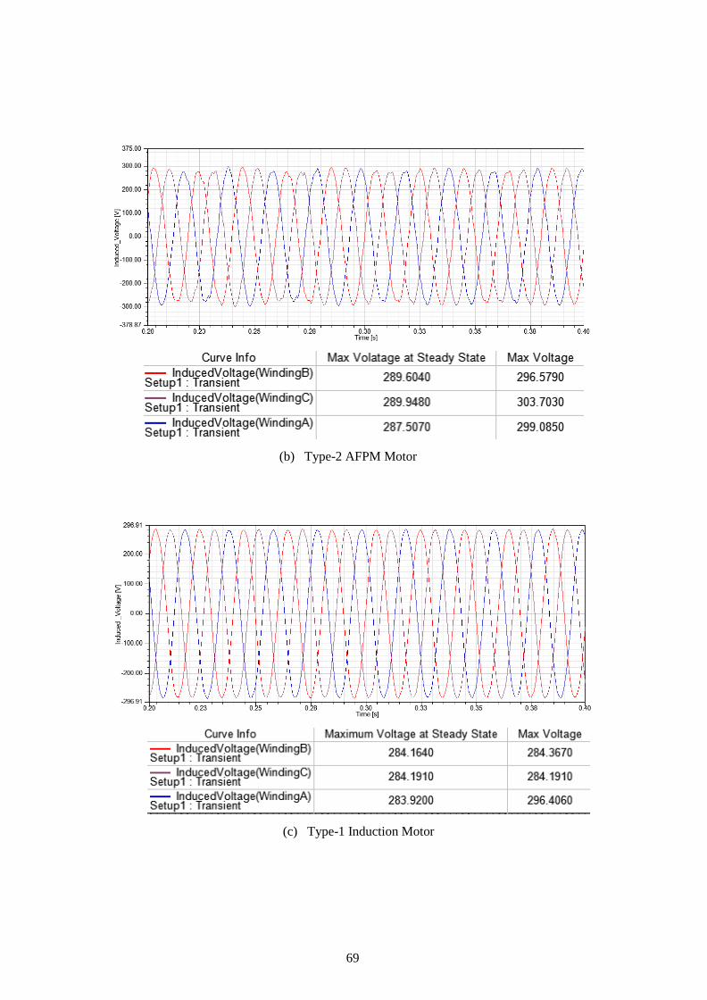
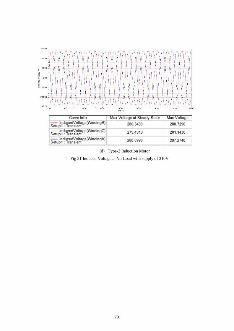
4.4.1 Induced Voltage
The induced voltage depends on the magnitude of magnetic flux and is given by the
equation
𝐸∅𝑟𝑚𝑠= 4.44 𝑁𝑓∅𝑚𝑎𝑥
Where ∅𝑚𝑎𝑥 is peak to peak magnitude of flux density, N are the numbers of turns and
f is the frequency. He simulations are ran for 1s but for the sake of better observable
behavior graph steady state period 0.2s to 0.3 s is magnified.
(a) Type-1 AFPM Motor
69
(b) Type-2 AFPM Motor
(c) Type-1 Induction Motor
70
(d) Type-2 Induction Motor
Fig 31 Induced Voltage at No-Load with supply of 310V
71
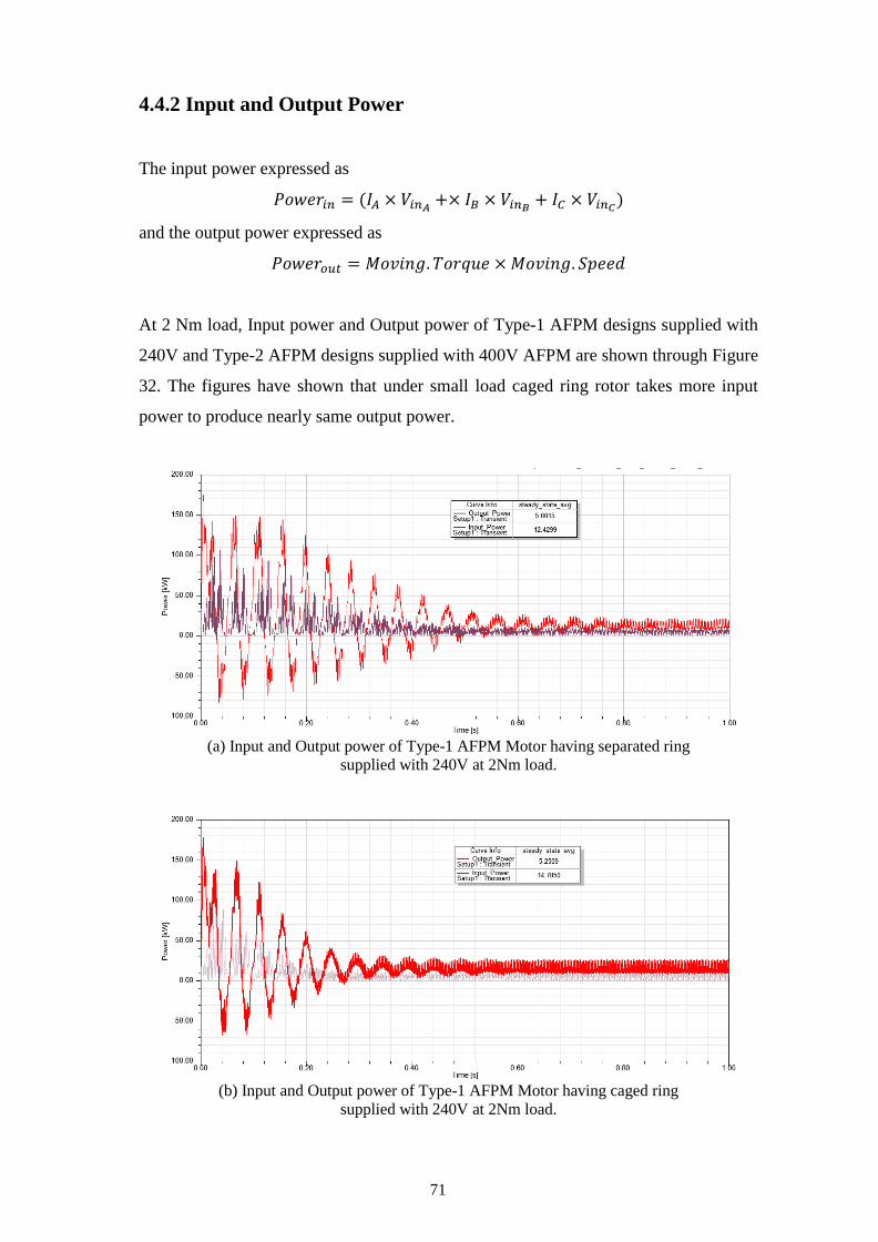
4.4.2 Input and Output Power
The input power expressed as
𝑃𝑜𝑤𝑒𝑟𝑖𝑛 = (𝐼𝐴 × 𝑉𝑖𝑛𝐴+× 𝐼𝐵 × 𝑉𝑖𝑛𝐵
+ 𝐼𝐶 × 𝑉𝑖𝑛𝐶)
and the output power expressed as
𝑃𝑜𝑤𝑒𝑟𝑜𝑢𝑡 = 𝑀𝑜𝑣𝑖𝑛𝑔. 𝑇𝑜𝑟𝑞𝑢𝑒 × 𝑀𝑜𝑣𝑖𝑛𝑔. 𝑆𝑝𝑒𝑒𝑑
At 2 Nm load, Input power and Output power of Type-1 AFPM designs supplied with
240V and Type-2 AFPM designs supplied with 400V AFPM are shown through Figure
32. The figures have shown that under small load caged ring rotor takes more input
power to produce nearly same output power.
(a) Input and Output power of Type-1 AFPM Motor having separated ring
supplied with 240V at 2Nm load.
(b) Input and Output power of Type-1 AFPM Motor having caged ring
supplied with 240V at 2Nm load.
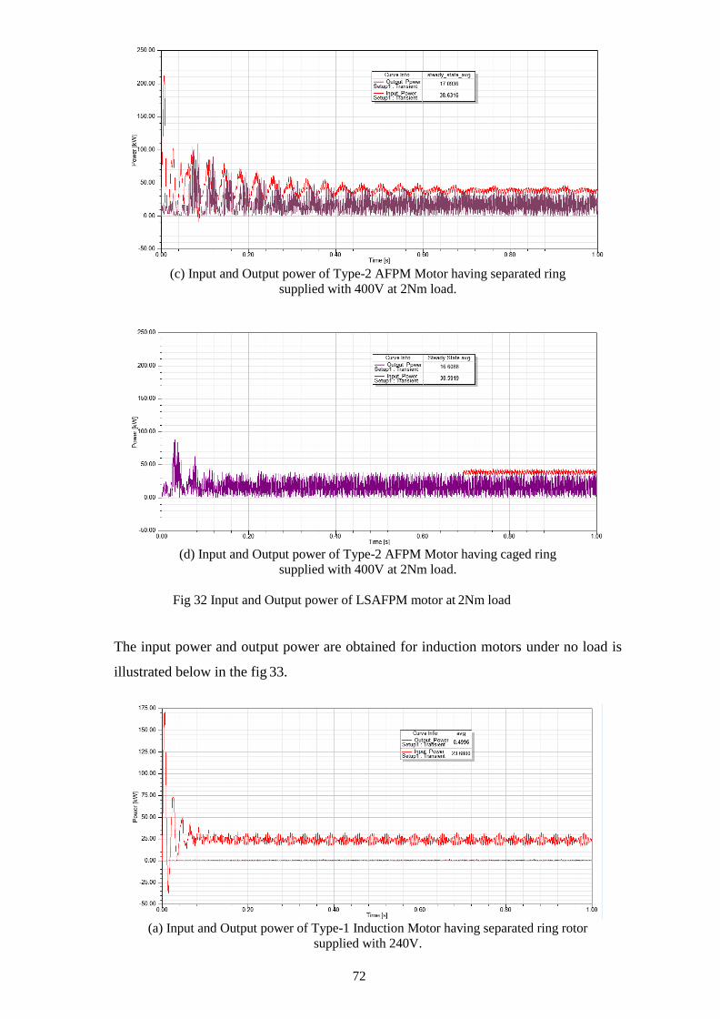
72
(c) Input and Output power of Type-2 AFPM Motor having separated ring
supplied with 400V at 2Nm load.
(d) Input and Output power of Type-2 AFPM Motor having caged ring
supplied with 400V at 2Nm load.
Fig 32 Input and Output power of LSAFPM motor at 2Nm load
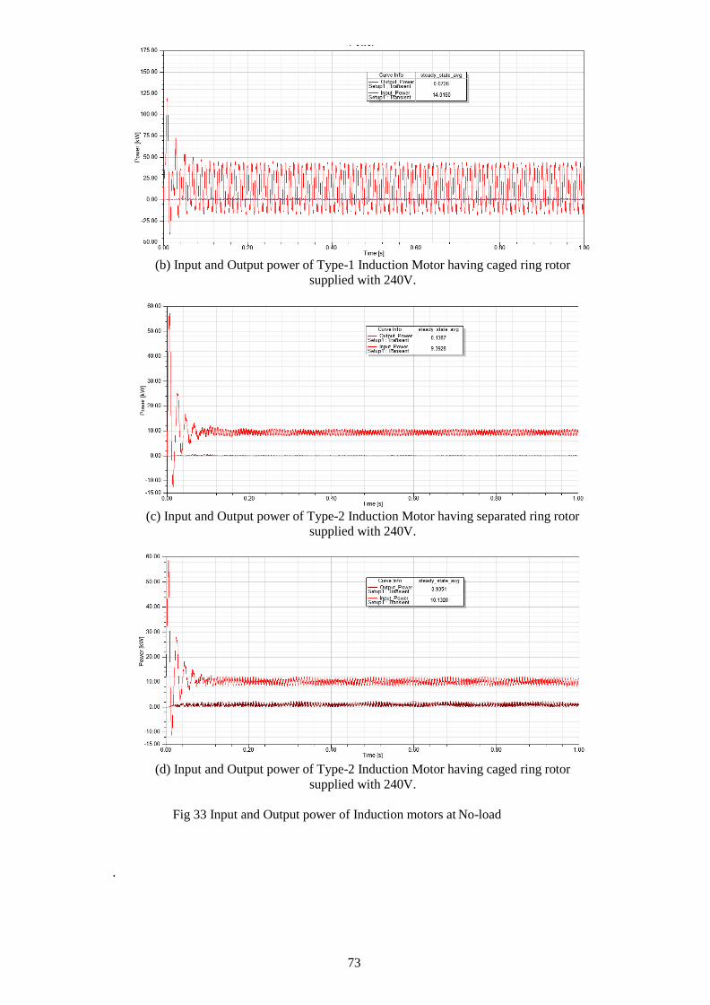
The input power and output power are obtained for induction motors under no load is
illustrated below in the fig 33.
(a) Input and Output power of Type-1 Induction Motor having separated ring rotor
supplied with 240V.
73
(b) Input and Output power of Type-1 Induction Motor having caged ring rotor
supplied with 240V.
(c) Input and Output power of Type-2 Induction Motor having separated ring rotor
supplied with 240V.
(d) Input and Output power of Type-2 Induction Motor having caged ring rotor
supplied with 240V.
Fig 33 Input and Output power of Induction motors at No-load
.

74
Figure 34 shows the power levels in Type-1 and Type-2 AFPM motors under load of
17Nm.
(a) Input and Output power of Type-1 AFPM Motor having separated ring rotor
supplied with 400V.
(b) Input and Output power of Type-1 AFPM Motor having caged ring rotor
supplied with 400V.
(c) Input and Output power of Type-2 AFPM Motor having separated ring rotor
supplied with 400V.

75
(c) Input and Output power of Type-2 AFPM Motor having caged ring rotor
supplied with 400V
Fig 34 Input and Output power of Type-1 and Type-2 AFPM at 17 Nm.
It can be seen from the figures that contrary to small load conditions, cage ring rotor
takes less input power than separate ring rotor to prodce nearly same output power. For
the load of 17Nm cage ring rotor improves the efficiency.

76
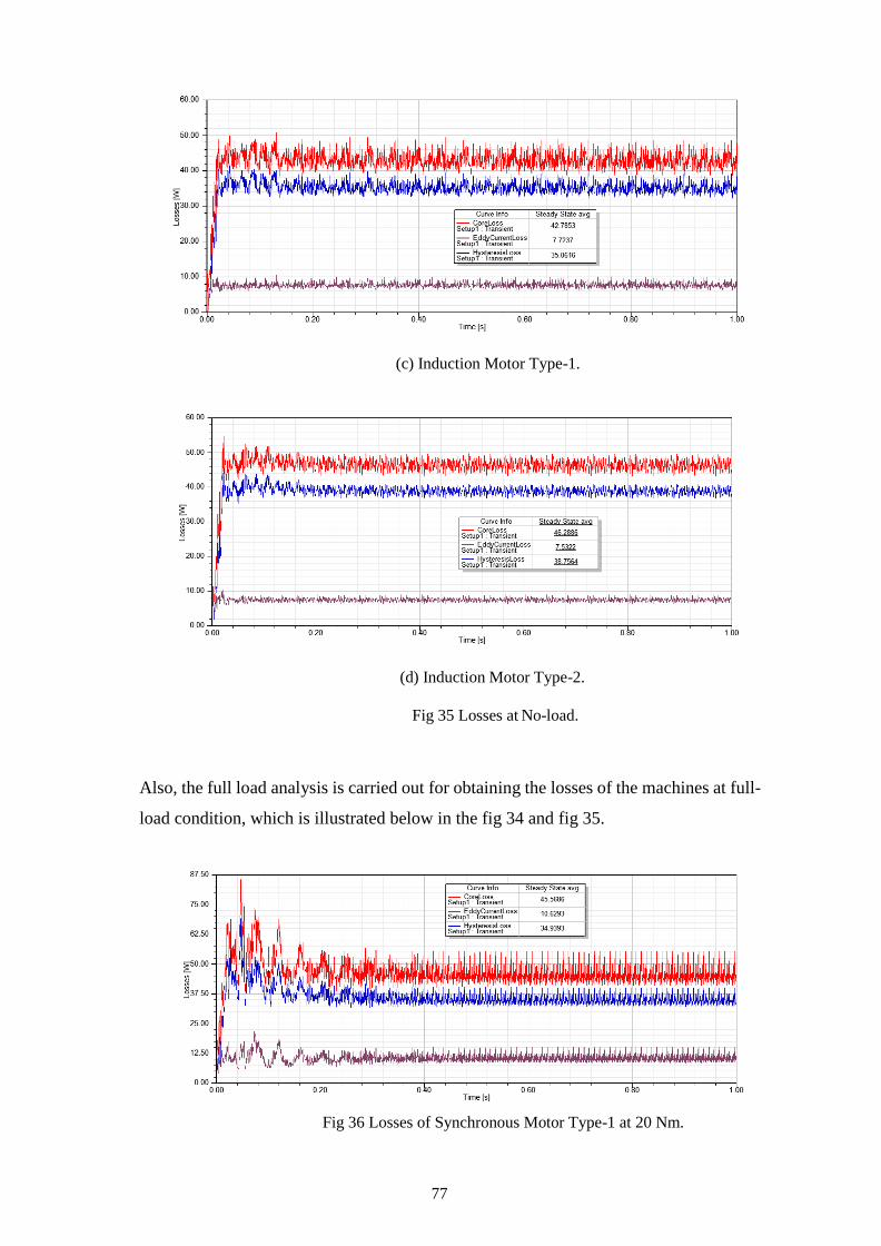
4.4.3 Losses
Core loss, hysteresis loss and eddy current losses are analyzed in fig 33,34 and 35. The
hysteresis losses in the machine produce because of the hysteresis effect of the material
used in the machine and the eddy currents losses are produced because of the induced
currents in the steel. The eddy current losses of the machine can be the reason of heating
of the machine. The results for losses are illustrated in the figure 33 for the no load
condition.
(a) Synchronous Motor Type-1.
(b) Synchronous Motor Type-2.
77
(c) Induction Motor Type-1.
(d) Induction Motor Type-2.
Fig 35 Losses at No-load.
Also, the full load analysis is carried out for obtaining the losses of the machines at full-
load condition, which is illustrated below in the fig 34 and fig 35.
Fig 36 Losses of Synchronous Motor Type-1 at 20 Nm.

78
Fig 37 Losses of Synchronous Motor Type-2 at 17 Nm.
Eddy current losses are more in design type-2 because of more inductor material
employed in geometry.

79
4.4.4 Efficiency
Efficiency of both the AFPM (Axial Flux Permanent Magnet) motor designs under
17Nm load are presented comparatively in the form of bar chart. Input and Output power
are used, and the steady state average efficiencies are labeled in the bar charts. Efficiency
is calculated from the expression stated
𝐸𝑓𝑓𝑖𝑐𝑖𝑒𝑛𝑐𝑦 =𝑂𝑢𝑡𝑝𝑢𝑡 𝑃𝑜𝑤𝑒𝑟
𝐼𝑛𝑝𝑢𝑡 𝑃𝑜𝑤𝑒𝑟× 100
Figure 38 shows efficiency of type-1 and type-2 designs where all the motors are fed
with 400V.
Fig 38 Efficiency plots of AFPM motors at 17Nm load
supplied with 400V.
It can be deduced from both the figure that efficiency improves on employing cage ring
rotor. Efficiency plot under 17Nm signifies that type-1 AFPM motor is better than type-
2 AFPM motor.

80
Chapter 5
Conclusion and Future Work
81
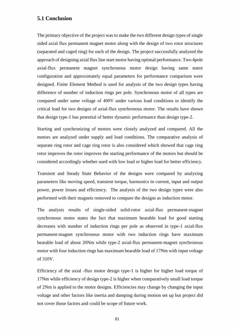
5.1 Conclusion
The primary objective of the project was to make the two different design types of single
sided axial flux permanent magnet motor along with the design of two rotor structures
(separated and caged ring) for each of the design. The project successfully analyzed the
approach of designing axial flux line start motor having optimal performance. Two 4pole
axial-flux permanent magnet synchronous motor design having same stator
configuration and approximately equal parameters for performance comparison were
designed. Finite Element Method is used for analysis of the two design types having
difference of number of induction rings per pole. Synchronous motor of all types are
compared under same voltage of 400V under various load conditions to identify the
critical load for two designs of axial-flux synchronous motor. The results have shown
that design type-1 has potential of better dynamic performance than design type-2.
Starting and synchronizing of motors were closely analyzed and compared. All the
motors are analyzed under supply and load conditions. The comparative analysis of
separate ring rotor and cage ring rotor is also considered which showed that cage ring
rotor improves the rotor improves the starting performance of the motors but should be
considered accordingly whether used with low load or higher load for better efficiency.
Transient and Steady State Behavior of the designs were compared by analyzing
parameters like moving speed, transient torque, harmonics in current, input and output
power, power losses and efficiency. The analysis of the two design types were also
performed with their magnets removed to compare the designs as induction motor.
The analysis results of single-sided solid-rotor axial-flux permanent-magnet
synchronous motor states the fact that maximum bearable load for good starting
decreases with number of induction rings per pole as observed in type-1 axial-flux
permanent-magnet synchronous motor with two induction rings have maximum
bearable load of about 20Nm while type-2 axial-flux permanent-magnet synchronous
motor with four induction rings has maximum bearable load of 17Nm with input voltage
of 310V.
Efficiency of the axial -flux motor design type-1 is higher for higher load torque of
17Nm while efficiency of design type-2 is higher when comparatively small load torque
of 2Nm is applied to the motor designs. Efficiencies may change by changing the input
voltage and other factors like inertia and damping during motion set up but project did
not cover those factors and could be scope of future work.
82
Magnetic analysis of the designs is considered to understand the magnetic behavior
inside the geometry of the designs. Magnetic flux density in the motor geometry through
the simulation period is analyzed for all the motor design when operating with and
without magnets. Air gap flux densities in all the synchronous motor designs are
comparatively analyzed. Distribution of current in rotor induction rings is shown with
current densities for all the design types.
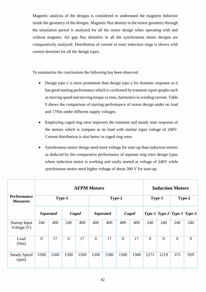
To summarize the conclusions the following has been observed.
• Design type-1 is more prominent than design type-2 for dynamic response as it
has good starting performance which is confirmed by transient report graphs such
as moving speed and moving torque vs time, harmonics in winding current. Table
9 shows the comparison of starting performance of motor design under no load
and 17Nm under different supply voltages.
• Employing caged ring rotor improves the transient and steady state response of
the motors which is compare at no load with similar input voltage of 240V.
Current distribution is also better in caged ring rotor.
• Synchronous motor design need more voltage for start-up than induction motors
as deduced by the comparative performance of separate ring rotor design types
where induction motor is working and easily started at voltage of 240V while
synchronous motor need higher voltage of about 300 V for start-up.
Performance
Measures
AFPM Motors
Induction Motors
Type-1 Type-2 Type-1 Type-2
Separated
Caged
Separated
Caged
Type-1
Type-2
Type-1
Type-2
Startup Input
Voltage (V)
240 400 240 400 400 400 400 400 240 240 240 240
Load
(Nm)
0 17 0 17 0 17 0 17 0 0 0 0
Steady Speed
(rpm)
1500 1500 1500 1500 1500 1500 1500 1500 1271 1219 375 959

83
Table 9 Performance measures across the motor design
5.2 Future work
Prototyping
Prototypes of the all the four motors are required for the affirmation of results obtained
through simulation software.
Other possibilities for the design
Although the motor is axial flux motor different magnetic field directions (radial,
circumferential) inside the magnet can affect the dynamic and steady state performance
depending on locking behavior between stator and rotor magnetic poles. So, different
designs with different magnetic flux lines direction in magnet could be designed and
analyzed in future studies. Single phase motor designs could also be possible for
comparative study.
Further Analysis
The fluctuations in steady response of the designed motors need further improvement by
optimizing the rotor geometry. The project compared the performances under different
load conditions.
The performance of the motor could also be analyzed with different load types such as
Rise Time (sec) 0.01 0.08 0.02 0.01 0.07 0.06 0.025 0.025 0.4 0.2 0.1 0.2
Settling Time
(sec)
0.7 0.3 0.4 0.2 0.5 0.5 0.2 0.2 0.4 0.2 0.5 0.2
Maximum
speed (rpm)
3025 3100 2950 3050 3100 2925 2650 2750 1280 1240 475 980

84
the step load, pulse load and ramp load.
Design type-2 can give higher efficiency if supply with high voltage and different motion
setup having different inertia and damping factor.
Motor performance can be further tested with using skewed induction rings. Different
possible induction rings structures are included in Appendices which are preliminary
designs and not used in this project and could be further optimized and tested.

85
References
[1] Knight, A. M. and C. I. McClay, "The design of high-efficiency line-start motors,"
IEEE Trans. Ind. Appl., Vol. 36, No. 36, 1555-1562, Nov./Dec. 2000.
[2] Aliabad, A. D., M. Mirsalim, and N. F. Ershad, "Line-start permanent-magnet
motors: Significant improvements in starting torque, synchronization, and steady-state
performance," IEEE Trans. Magn., Vol. 46, No. 12, 4066-4072, Dec. 2010.
[3] Mirimani, S. M., A. Vahedi, and F. Marignetti, "Effect of inclined static eccentricity
fault in single stator-single rotor axial flux permanent magnet machines," IEEE Trans.
Magn., Vol. 48, No. 1, 143-149, Jan. 2012.
[4] De la Barriere, O., S. Hlioui, H. Ben Ahmed, M. Gabsi, and M. LoBue, "3-D formal
resolution of Maxwell equations for the computation of the no-load flux in an axial flux
permanent-magnet synchronous machine," IEEE Trans. Magn., Vol. 48, No. 1, 128-136,
Jan. 2012.
[5] De Donato, G., F. G. Capponi, and F. Caricchi, "No-load performance of axial flux
permanent magnet machines mounting magnetic wedges," IEEE Trans. Ind. Electron.,
Vol. 59, No. 10, 3768-3779, Oct. 2012.
[6] Z. Bingyi, Z. Wei, Z. Fuyu, F. Guihong, “Design and Starting Process Analysis of
Multipolar Line-Start PMSM,” Proc. ICEMS 2007, Seoul, 8-11 Oct., 2007, pp. 1629-
1634.
[7] Sitapati, K., Krishnan, K., Performance Comparisons of Radial and Axial Field,
Permanent Magnet, Brushless Machines, IEEE Transactions on Industry Applications,
Vol. 37, No. 5, Sept./Oct. 2001.
[8] Dean J Patterson, Jessica L Colton, Brad Mularcik, Byron J Kennedy, Steven
Camilleri, Rafal Rohoza,” A Comparison of Radial and Axial Flux Structures in
Electrical Machines”
[9] Campbell P, Rosenberg DJ, Stanton DP (1981). The Computer Design and
Optimization of Axial-Field Permanent Magnet Motors. IEEE Trans. Power Apparatus
Syst. PAS-100(4): 1490-1497.
[10] Chan CC (1987). Axial-Field Electrical Machines - Design and Applications. IEEE
Trans. Energy Conversion. EC-2(2): 294-300.
[11] Platt D (1989). Permanent Magnet Synchronous Motor with Axial Flux Geometry.
IEEE Trans. Magnet., 25(4): 3076-3079.
[12] Parviainen, A., Niemela, M., Pyrhonen, J., Mantere, J., Performance comparison
between low-speed axial-flux and radial-flux permanent magnet machines including
mechanical constraints, IEEE International Conference on Electric Machines and
Drives, May 2005, pages 1695-1702.
[13] A. Mahmoudi, N. A. Rahim, and W. P. Hew "Axial-Flux Pemanent Magnet
Machine Modeling, Design, Simulation, and Analysis," Scientific Research and Essay
(SRE), Vol. 6, No. 12, 2525-2549, June 2011.
[14] A. Mahmoudi, N. A. Rahim, and W. P. Hew, "Analytical Method for Determining
Axial-Flux Permanent-Magnet Machine Sensitivity to Design Variables," Intemational
Review of Electrical Engineenng (IREE), Vol. 5, No. 5, 2039-2048, September-October
2010.
[15] A. Mahmoudi, N. A. Rahim, and W. P. Hew, "Al Analylical Complementary FEA
Tool for Optimizing of Arial-Flux PermanentMagnet Machines," Intemational Joumal
of Applied Electromagnetics Machines (IJEAM), Vol. 37, No. 1, 19-34, September
2011.
[16] A. Mahmoudi, N. A. Rahim, and W. P. Hew "Axial-Flux PermanentMagnet Motor
Design for Electnc Vehicle Direct Drive using Sizing Equation and Finite Element
Analysis" Progress [n Electromagnetics Research (PIER), Vol. 122, 467 -496, 2012.
[17] A. Mahmoudi, S. Kahourzade, N. A. Rahim, and H. W. Ping, "Improvement to
Performance of Solid-Rotor-Ringed Line-Start AxialFlux Permanent-Magnet Motor,"
Progress In Electromagnetics Research, Vol. 124, 383-404, 2012.
[18] S. Geetha and D. Platt, "Axial flux permanent magnet servo motor with sixteen
poles," Industry Applications Society Annual Meeting, 1992., Conference Record of the
1992 IEEE.
[19] Chan TF, Lai LL, Shuming X (2009). Field Computation for an Axial Flux
Permanent-Magnet Synchronous Generator. IEEE Trans. Energy Conversion, 24(1): 1-
11.

[20] Furlani EP (1994). Computing the Field in Permanent-Magnet Axial-Field Motors.
IEEE Trans. Magnetics. 30(5): 3660-3663.
[21] Lee JK (1992). Measurement of Magnetic Fields in Axial Field Motors. IEEE
Trans. Mag., 28(5): 3021-3023.
[22] Kano Y, Kosaka T, Matsui N (2010). A Simple Nonlinear Magnetic Analysis for
Axial-Flux Permanent-Magnet Machines. IEEE Trans. Ind. Electronics, 57(6): 2124-
2133.
[23] Loureiro LTR, Filho AFF, Zabadal JRS, Homrich RP (2008). A Model of a
Permanent Magnet Axial-Flux Machine Based on Lie's Symmetries. IEEE Trans. Mag.,
44(11): 4321-4324.
[24] Qamaruzzaman AP, Dahono P (1997). Analytical Prediction of Inductances of
Slotless Axial-Flux Permanent Magnet Synchronous Generator Using Quasi-3D
Method. Int. J. Elect. Eng. Inf., 1(2): 115125.
[25] Zhilichev YN (1998). Three-Dimensional Analytic Model of Permanent Magnet
Axial Flux Machine. IEEE Trans. Mag., 34(6): 3897-3901.
[26] Azzouzi J, Barakat G, Dakyo B (2005). Quasi-3-D Analytical modeling of the
magnetic Field of an Axial Flux Permanent-Magnet Synchronous Machine. IEEE Trans.
Energy Conversion Actions. 20(4): 746-752.
[27] Kurronen P, Pyrhonen J (2007). Analytic Calculation of Axial-Flux Permanent-
Magnet Motor Torque. IET J., 1(1): 59-63.
[28] Marignetti F, Colli VD, Carbone S (2010). Comparison of Axial Flux PM
Synchronous Machines With Different Rotor Back Cores. IEEE Trans. Mag., 46(2):
598-601.
[29] Bumby JR, Martin R, Mueller MA, Spooner E, Brown NL, Chalmers BJ (2004).
Electromagnetic Design of Axial-Flux Permanent Magnet Machines. IET J., 151(2):
151-160.
[30] Chan TF, Weimin W, Lai LL (2010). Performance of an Axial-Flux Permanent
Magnet Synchronous Generator from 3-D Finite-Element Analysis. IEEE Trans. Energy
Conversion, 25(3): 669-676.
[31] Rong-Jie W, Kamper MJ (2004). Calculation of Eddy Current Loss in Axial Field
Permanent-Magnet Machine with Coreless Stator. IEEE Trans. Energy Conversion,
19(3): 532-538.
[32] Upadhyay PR, Rajagopal KR (2006). FE Analysis and Computer-Aided Design of
a Sandwiched Axial-Flux Permanent Magnet Brushless DC Motor. IEEE Trans. Mag.,
42(10): 3401-3403.
[33] Sang-Ho L, Su-Beom P, Soon OK, Ji-Young L, Jung-Jong L, Jung-Pyo H (2006).
Characteristic Analysis of the Slotless Axial-Flux Type Brushless DC Motors Using
Image Method. IEEE Trans. Mag., 42(4): 1327-1330.
[34] Almeida, AT de, Ferreira, F and Duarte, A (2014), ‘Technical and Economical
Considerations on Super High-efficiency three-phase motors,’ IEEE Trans. Ind. Appl.,
vol. 50, no.2, pp. 1274-1285
[35] Seda Küla , Osman Bilgina , Mümtaz Mutluerb (2015), ‘Application of Finite
Element Method to Determine the Performances of the Line Start Permanent Magnet
Synchronous Motor,’ Procedia - Social and Behavioral Sciences 195 ( 2015 ) 2586 –
2591

Appendices
Appendix A: Stator Excitation Setting.
Appendix B: Mesh plots.

Appendix A: Stator Excitation Setting


92
Appendix B: Mesh plots
Stator Mesh
Rotor Disk Mesh
Coil Mesh

93
Induction Rings Mesh for Type-1 design
Magnet mesh for Type-1 design
94
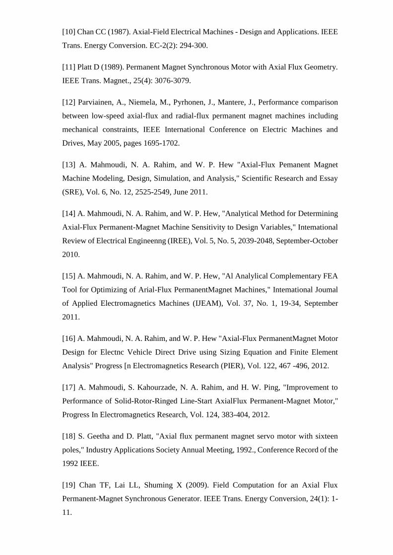
Induction Rings Mesh for Type-2 design
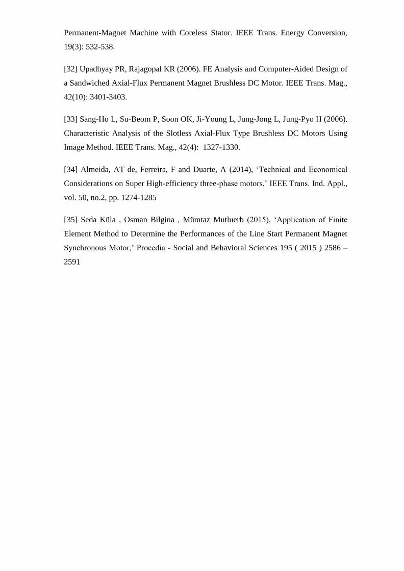
Magnet mesh for Type-2 design

95
Appendix C: Exploded view of quarter of geometry used in
simulation
Exploded view of quarter of type-1 axial-flux permanent motor with
separated ring
96
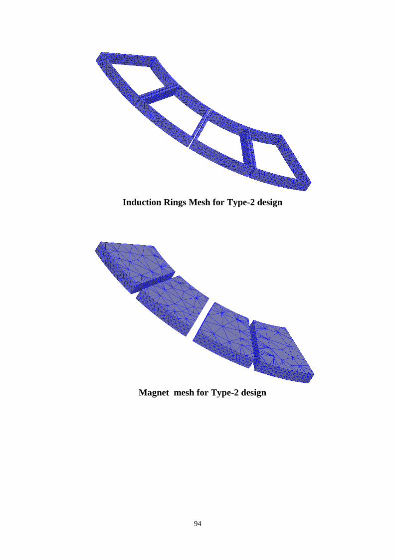
Appendix D: Other geometry designs made, and simulation performed
during the project
Starting performance of type-1 Axial-flux permanent-magnet motor having
separated ring with single magnet in quarter

97
Starting performance of type-1 Axial-flux permanent-magnet motor having
caged ring with single magnet in quarter

98
PRELIMINARY STATOR DESIGNS FOR AXIAL FLUX MOTOR

99
PRELIMINARY ROTOR DESIGNS FOR AXIAL FLUX MOTOR


![Design of Axial-Flux Motor for Traction Applicationradial-flux motors, the axial-flux ones can be modulated which leads to the increase of their torque generation capabilities [1,2,4]](https://img.pdfslide.us/doc/110x75/5e7ecdb1efdfb0767a23aa9b/design-of-axial-flux-motor-for-traction-application-radial-flux-motors-the-axial-flux.jpg)