Embed Size (px)
Citation preview

International Journal of Engineering Research & Technology (IJERT)
ISSN: 2278-0181http://www.ijert.org
IJERTV10IS030027(This work is licensed under a Creative Commons Attribution 4.0 International License.)
Published by :
www.ijert.org
Vol. 10 Issue 03, March-2021
17
Design and Analysis of SAE Supra Chassis
Kondusamy V1, Poovarasan K2, Raguram R S3 , Vivekanandhan M4, Vyshaak R B5, Vignesh G6
1 Assistant Professor, Department of Automobile Engineering, Karpagam college of Engineering, Coimbatore, Tamilnadu. 2,3,4,5,6 Students, Department of Automobile Engineering, Karpagam college of Engineering, Coimbatore, Tamilnadu.
1. INTRODUCTION
The chassis shape must competently assist the
burden of the car components and transmit loads that result
from longitudinal, lateral and vertical accelerations which
might be experienced in a racing environment without
failure. This paper probes the diverse components of chassis
design. Some important questions addressed are: What is the
high-quality manner to transfer the hundreds via the
structure? How stiff ought to the body be? How a chassis has
impact on exceptional race situation? What is the effect of
pipe diameter and pass phase at the stiffness of the chassis?
What need to be the appropriate component of protection
whilst designing a body?
Supra SAE India is a countrywide degree pupil
opposition, organized with the aid of Society of Automobile
Engineers India, wherein students are asked to layout,
manufacture and run a prototype of open wheel racing
automobile. This competition is performed annually in India
and approximately a hundred and eighty faculties take part
each year from throughout India.
Following the technical inspection are the sub
events which include the static occasions like tilt test, brake
check, price report presentation, engineering layout report
and business presentation, dynamic events like acceleration
check, skid pad, autocross and persistence test. In this
excessive octane state of affairs, an automobile is expected
to carry out high on acceleration, dealing with, braking,
aesthetics, ergonomics, fabrication and renovation with least
funding in fabrication without compromising on protection
of the driver. The motive of the thesis is to design and
manufacture tubular space frame chassis that should be
robust enough to take in the power while the front, lower
back, side, torsional loads are applied.
For the cause of the application on a high overall
performance racing automobile, it has to meet the following
criteria:
• Minimize the weight to stiffness ratio
• Maintain Low Center of Gravity
• Reasonable material and manufacturing costs
• Create a solid base chassis to evolve on for years to
come
• Aesthetically pleasing design
The Chassis
The number one objective of the chassis is to offer
a shape that connects the front and rear suspension without
immoderate deflection. When considering a race car chassis,
a frame this is effortlessly twisted will result in massive
coping with troubles. The lateral loading on a vehicle is
taken up in places; the frame and the suspension.
Fig 1.1 SAE Supra Chassis
The suspension may be adjusted, the frame cannot.
So to get required dealing with, the frame have to be stiffer
to compensate lateral loading on the auto. On the whole, a
frame that is capable of preserve torsional loads resulting
from inertial accelerations of components experienced in the
course of cornering or from carried out hundreds acting on
one or opposite corners of the car will almost continually be
sufficiently robust.
Material Selection
The integrity of a layout may be ensured only after
a scientific material selection method. Since the chassis
needs to be designed for harsh riding situations, the choice
of material turns into a critical part of design method.
The mechanical Structural Performance Analysis
of SAE Supra Chassis 241 houses such elasticity modulus E,
the shear modulus G, density ρ and yield stress fy are
important from design point of view. For selection of
suitable fabric for chassis, prepare a selection matrix of
critical aspect which can have an effect on the overall
performance of the auto’s mechanical houses, fee and
availability.
The chassis undergoes various kinds of forces at
some stage in locomotion, it has to live intact without
yielding, and it must be stiff to absorb vibrations,
additionally it need to withstand excessive temperatures.
The fabric assets of the chassis are an important criterion at
the same time as designing and manufacturing the
automobile. A tubular space body chassis became chosen
over a monocoque chassis notwithstanding being heavier
because, its manufacturing is cost effective requires simple
tools and damages to the chassis may be effortlessly
rectified. The very typically used substances for making the
distance body chassis are Chromium Molybdenum metal
(Chromoly) and SAE-AISI 1018.
Both those materials had been analyzed for specific
parameters and subsequently decided on to apply Chromoly
metal 4130 for making the tubular area body chassis due to
several reasons. SAE 1018 grade steel is better in phrases of
Thermal homes however weaker than Chromoly in terms of

International Journal of Engineering Research & Technology (IJERT)
ISSN: 2278-0181http://www.ijert.org
IJERTV10IS030027(This work is licensed under a Creative Commons Attribution 4.0 International License.)
Published by :
www.ijert.org
Vol. 10 Issue 03, March-2021
18
power. But the primary precedence of layout is protection
for the driver therefore the fabric with better stiffness and
energy changed into chosen.
The material must no longer motive any failure
even underneath extreme situations of using as described in
the rule e book. Chromoly metal 4130 exhibits better
structural property than SAE 1018 Grade steel for this
reason the former turned into taken into consideration as the
primary cloth for building a tubular area body chassis. Even
though the cost of Chromoly is marginally higher than that
of SAE 1018 grade steel, the protection of the driving force
remains the maximum priority for the team.
Change in Young’s Modulus with respect to
Compressive Stress
The cloth reveals a three hundred% boom in
Young’s modulus (80 MPa), considerable transition from a
bendy low modulus as-organized figure. We count on latent
heat of solidification to be released into the matrix, but,
estimated dissipation time primarily based on Fourier’s
regulation shows that the change in temperature would be in
large part unnoticeable. In contrast, the EGaIn sample
fractured upon compression whilst stable FM composites
display a statistically insignificant growth in stiffness.
To affirm differences in mechanical houses of the
compressed samples, we issue the substances to excessive
stresses, expecting that shape alternate and network
formation will differentiate compressed ST3R composite
from stable FM samples. Besides the larger (300%) initial
stiffness for ST3R, we found an asymptotic mechanical
response previous to yielding, similar to plastic deformation
in metals. The networks spoil as pressure is accelerated,
main to the knocking down of the strain–pressure curve at
better strains.
This phenomenon is similarly investigated by
varying the volume of filler. When f = 30%, the pre-
compressed ST3R and strong FM samples gave similar
modulus (12–15 MPa). At f=50%, but, a dramatic exchange
in modulus is located in the ST3R. This is consistent with
the formation of networks whereby a minimum filler
quantity is required.
MATERIAL
PROPERTY AISI 1018 AISI 4130
Brinell hardness 130-140 200-300
Tensile strength 430-480 (MPa) 530-1040 (MPa)
Yield strength 240-400 (MPa) 440-980 (MPa)
Shear strength 280-300 (MPa) 340-640 (MPa)
Thermal conductivity 52 (W/m-K) 43 (W/m-K)
Thermal shock resistance 14-15 (points) 16-31 (points)
Chromium content 0 % 0.8-1.1 %
Thus the material AISI 4130 proves to be most
desirable even with the higher cost for a greater safety.
Fig 1.2 Changes in Compressive Stress
Normalized Complex Stiffness
The alternate in elasticity ought to appear as an
asymmetry inside the distribution of complicated stiffness
leading to a unique trend in skewness for the ST3R
composite under dynamic stress compared to static
(nonresponsive) analogous composites (e.g. EGaIn, strong
FM or glycerol). To verify this inference, we achieved
dynamic tensile stress on skinny rectangular samples at 1
Hz, with growing amplitudes from 5–15% stress. As
anticipated, ST3R composite suggests a boom in complex
stiffness as strain is expanded, assisting the notion of a strain
hardening cloth.
We infer that the rise in complicated stiffness is a
result of partial solidification of the below cooled liquid
steel, triggered by way of deformation of the composite. In
evaluation, EGaIn fillers show a small initial upward thrust
in normalized complicated stiffness before a decrease as
pressure is expanded. Additional manage experiments of
solid FM particles, glycerol droplets, and PDMS (matrix) in
addition show a decrease in stiffness as stress is expanded,
highlighting the unique behavior of the ST3R.
We also observed a shift in skewness of the
distribution of complicated stiffness, whereby effective
values represent bias within the mass of the distribution
toward decrease stiffness and terrible values point towards
better stiffness. It is consequently glaring that only the ST3R
composite displayed a shift towards higher complex
stiffness. Although stiffness is enhanced after mechanical
loading, the boom is at the order of 10%.
Fig 1.3 Vehicle Loading

International Journal of Engineering Research & Technology (IJERT)
ISSN: 2278-0181http://www.ijert.org
IJERTV10IS030027(This work is licensed under a Creative Commons Attribution 4.0 International License.)
Published by :
www.ijert.org
Vol. 10 Issue 03, March-2021
19
Vehicle Loading
Frame is described as a fabricated structural
meeting that supports all purposeful car structures. This
meeting can be a single welded structure, multiple welded
structures or an aggregate of composite and welded systems.
Depending upon utility of loads and their path, chassis is
deformed in respective manner proven beneath.
• Longitudinal Torsion - Created specially by a cornering
automobile or bumps in the racetrack. It is the chassis
capacity to withstand deformation below this load that
defines torsional stiffness.
• Vertical Bending - Vertical bending is created by means
of the load of the power and automobile’s components, those
forces may be boosted through vertical acceleration
produced.
• Horizontal Bending - This deformation mode is as a result
of the centrifugal forces created with the aid of the cornering
of the car.
• Horizontal Lozenging - Occurs whilst the automobile
deforms into a parallelogram-like shape, that is caused by
the choppy or opposing application of pressure at the wheels
on opposite facets of the auto.
Effect of Chassis on Different Race Condition
The SAE Supra competition is scored based on two
areas, static and dynamic testing, with both having diverse
sub-categories. The dynamic section includes 4 occasions;
acceleration, skid pad, autocross and staying power. Each of
those events needs extraordinary overall performance from
the chassis. It is a balancing act to reap foremost overall
performance from the vehicle.
Acceleration: This event surely needs a vehicle that
can reach excessive speeds quick, hence looking at
Newton’s 2d law of movement F = ma; accordingly, low
mass of chassis will deliver higher acceleration.
Skid pad: This event is a degree of the car’s
cornering potential around a flat nook. To achieve this, the
chassis is required to have an excessive cost of torsional
stiffness that is properly balanced all through the chassis.
Autocross: The Autocross event is a standard race
track comprising of a straight, regular turns and some
different varieties of turns. Cars run at the tune with the
average speed among 40–48 km/h. This occasion is designed
to measure the automobile’s favored overall performance
effects of dealing with, acceleration and breaking. Thus
higher torsional stress of the chassis will yield higher
managing.
Endurance: The very last event is the measure of
the automobile’s reliability, patience and gas economic
system. The fuel economic system but will be motivated via
the car’s chassis, as any superfluous weight will gradual the
auto down consequently lowering financial system.
Dynamic Loading
Lateral Load Transfer: When cornering in a steady
flip, load is transferred from the internal pairs of the wheels
to the outside pair because of centrifugal pressure. This load
switch is called lateral load transfer.
Lateral Load Transfer (Lb.) = (Lateral Acceleration
* Center of Gravity * Weight) / Track Width
= (1.5 * 10 * 705.479) / 48
Lb. = 220.462 lbs. = 99.99 kg
Force = 99.99 * 9.8 = 979.902 N
Lateral bending is because of the weight switch
while cornering that is same to centrifugal pressure and as a
result the pressure of 4774. Three N is acted on the side
effect member in cockpit, consequently the equal stress is
calculated (246 MPa) that is well beneath permissible limit.
Thus fabric will no longer begin to yield all through
lateral bending. Longitudinal Load Transfer: Such load
switch occurs in a longitudinal plane underneath linear
acceleration or deceleration
Longitudinal Load Transfer (Lb.) = (Acceleration *
Center of Gravity * Weight) / Track Width
= (1.5 * 10 * 731.667) / 68
Lb. = 161.397 lbs. = 73.209 kg
Force = 73.209 * 9.8 = 717.448 N
Acceleration and Brake
Test Due to inertia effect, acceleration forces
generally tend to act in opposite course to the motion of
body. The mass of driver is assumed 70 kg and power train
50 kg and acceleration of engine is three.7 m/s2. As
calculated above, longitudinal pressure is implemented on
the main hoop; and simultaneous static load because of force
and drive teach is acted downward in cockpit region.
Equivalent pressure is calculated for this dynamic take a
look at which comes as 221 MPa. This is much less than the
permissible stress 435 MPa, as a consequence chassis is
secure.
Impact Loading
Type of
impact
forces
Boundary
conditions
Force that
chassis
can
withstand
after the
impact
Von
mises
stress
(MPa)
FOS
Front
impact
Clamping
all
suspension
pickup
points and
applying
force on
front bulk
head
9G 261 1.76
Side
impact
Clamping
all
suspension
pickup
points and
applying
force on
side impact
member
5G 114 4.03
The characteristic of the frame is to provide the car
electricity, structural integrity and to protect the driving
force (in case of serious impacts and rollover) and help the
front and rear suspension structures, engine, drive educate,
steerage system and other structures in the vehicle. It has to
be of good enough strength to guard the motive force in case
of a coincidence.

International Journal of Engineering Research & Technology (IJERT)
ISSN: 2278-0181http://www.ijert.org
IJERTV10IS030027(This work is licensed under a Creative Commons Attribution 4.0 International License.)
Published by :
www.ijert.org
Vol. 10 Issue 03, March-2021
20
Selection of Theory of Failure
Since all of the checks are completed underneath
static structural, the go phase of the issue is thought to be
uniform during, but in exercise due to some irregularities,
fluctuating load can lead to fatigue failure. These fluctuating
masses are very difficult to calculate and so it is usually
desired to have a better issue of safety. It is visible that
Distortion Energy Theory (Huber Von Mises and Hencky’s
Theory) predicts yielding with unique accuracy in all four
quadrants. Moreover, Distortion Energy Theory is used for
ductile materials, while the element of safety is to be held in
close limits and the cause of failure of the element is being
investigated. This concept predicts failure most correctly.
Thus, some of the 3 theories, i.e. Max. Principle Stress
Theory, Max. Shear Stress Theory and Distortion Energy
Theory, Distortion Energy Theory was selected for
designing the chassis.
Torsional Rigidity
It is the torsional reaction of a structure to an
applied torque loading. An exceptional feasible chassis
might be one that has high stiffness; with low weight and
fee. If there is enormous twisting, the chassis will vibrate,
complicating the machine of the automobile and sacrificing
the coping with overall performance. It is proper to layout a
chassis with maximum torsional stress. This allows the
suspension to do their job efficaciously. In order to design
an automobile of most torsional stiffness, the premise or
generalized equation for torsion must be tested. Figure
beneath is a primary shaft confined at one end and an applied
torque T at the opposite, with Φ denoting the ensuing twist
of the shaft.
Fig 1.4 Torsional Rigidity
T = ΦJG / l
This equation can then be rearranged to express torsional
stiffness,
T / Φ = JG / l
This expression presentation that torsional stiffness
in proportion to each the polar moment inertia and fabric
shear modulus, while being inversely proportional to the
period.
The torsional stress can be calculated via locating
the torque implemented to the frame and dividing by using
the angular deflection.
K = R / θ
K = (F * L) / tan-1 ((∆y1 +∆y2) / 2L)
where,
K - Torsional Stiffness
T - Torque
θ - Angular deformation
F - Shear Force
y1, y2 - Translational displacement
Applied
moment
(Nm)
Deflection
(m/deg)
Stiffness
(Nm/deg)
2.4 mm
wall
thickness
450 0.10368 480
3.4 mm
wall
thickness
450 0.034 1470
Force applied 1130 N
y1 = y2 1.68 mm = 0.00168 mm
L 0.20
K = (1130 * 2) / tan-1 ((0.00168 + 0.00168) / (2 * 0.20))
K = 482 Nm / deg
Deakin et al. Concluded that a Formula SAE racer,
which has a total suspension roll stiffness of 500–1500
Nm/deg, requires chassis stiffness among three hundred and
one thousand Nm/deg to permit the dealing with to be tuned.
Effect of Wall
Thickness on Torsional Stiffness from the given
table, it can be inferred that the thickness of the frame has
the maximum impact on the torsional stiffness. The torsional
stiffness increases three instances with 1 mm boom in frame
thickness. Thus, it will increase stiffness notably and not
using a great growth within the weight of the chassis and
growing the stiffness to weight ratio of the chassis
improving the coping with of the auto.
2. LITERATURE REVIEW
❖ SHUBHAM THOSAR, ANTRIKSH MUTHA and
S.A. DHARURKAR discussed in detail in
Innovative Design and Development Practices in
Aerospace and Automotive Engineering, Lecture
Notes in Mechanical Engineering DOI
10.1007/978-981-10-1771-1_27 about the
Structural Performance Analysis of SAE Supra
Chassis.
❖ ABHIJEET DAS discussed in detail in
International Journal of Science and Research
(IJSR) ISSN (Online): 2319-7064 Volume 4 Issue
4, April 2015 about the Design of Student Formula
Race Car Chassis
❖ SWATI UPADHYAY, GANESH BADIGER
discussed in detail in International Research
Journal of Engineering and Technology (IRJET)
Volume: 07 Issue: 05 May 2020 about the Design

International Journal of Engineering Research & Technology (IJERT)
ISSN: 2278-0181http://www.ijert.org
IJERTV10IS030027(This work is licensed under a Creative Commons Attribution 4.0 International License.)
Published by :
www.ijert.org
Vol. 10 Issue 03, March-2021
21
and Analysis of Supra Chassis
❖ PROF. DHAWARE P.A., MISTRY P.T., JOSHI
K.S., KARDILE O.B., KALE G.R discussed in
detail in IOSR Journal of Engineering (IOSR JEN)
ISSN (e): 2250-3021, ISSN (p): 2278-8719,
Special Issue June-2019, PP 81-85 about Design
and Analysis of Supra Car
❖ SHUBHANANDAN DUBEY, RAHUL
JAISWAL, RAUNAK MISHRA discussed in
detail in International Journal of Recent Trends in
Engineering & Research (IJRTER) Volume 03,
Issue 03; March - 2017 [ISSN: 2455-1457] about
Design of Chassis of Student Formula Race Car
❖ AVINASH BARVE1, SANKET LAKHE
discussed in detail in International Journal of
Science and Research (IJSR) ISSN (Online): 2319-
7064 Volume 7 Issue 6, June 2018 about Detailed
Design Calculation & Analysis of Student Formula
3 Race Car
❖ PRASHANT SAHGAL under the guidance of ER.
RAMENDRA SINGH NIRANJAN discussed
about Design and structural performance analysis
of Supra SAE car chassis
❖ AMOGH RAUT, ANIKET PATIL discussed in
detail in International Journal of Engineering and
Advanced Technology (IJEAT) ISSN: 2249 –
8958, Volume-7 Issue-1, October 2017 about
Design Analysis of Chassis used in Students’
Formula Racing Car using FEA Tool
❖ AJAY KASHIKAR, SHREYAS MHATRE,
ANISH, RAHUL CHAVAN, ABHISHEK
SHUKLA discussed in detail in International
Journal of Research Publications in Engineering
and Technology [IJRPET] ISSN: 2454-7875
VOLUME 3, ISSUE 3, March-2017 about Design
and Analysis of Formula Car Chassis
❖ ANKIT PATIL, SAAHIL PATIL, MONIK SHAH,
NITIN SALL discussed in detail in International
Journal of Scientific & Engineering Research
Volume 9, Issue 3, March-2018 about Design and
Analysis of Suspension System with Different
Material for SUPRA SAE INDIA 2018
❖ MOHIT SINHA discussed in detail in International
Journal of Innovative Research in Science,
Engineering and Technology Volume 5 Issue 4
April 2016 about Design of a space frame race car
chassis entailing rectification of preceding flaws
with apt ergonomic considerations, material
selection and Impact analysis
❖ William B. Riley and Albert R. George discussed
in detail in SAE Technical Paper Series Reprinted
from: Proceedings of the 2002 SAE Motorsports
Engineering Conference and Exhibition (P-382)
about Design, Analysis and Testing of a Formula
SAE Car Chassis.
❖ Dr. Tanveer Singh Chawla and Mr. Eric Leonhardt
discussed in detail in 2018 ASEE Annual
Conference & Exposition about Two Approaches
to Optimize Formula SAE Chassis Design Using
Finite Element Analysis
❖ Jannis D.G. van Kerkhoven, 516303 DCT
2008.154 discussed in detail in Technische
Universiteit Eindhoven Department Mechanical
Engineering Dynamics and Control Technology
Group about Design of a Formula Student race car
chassis
❖ Ranjit Kale, Nagesh Koli, Darshan Sonawane,
Dipesh Garud, Rohan Korpenwar discussed in
detail in International Journal of Innovative
Research in Science, Engineering and Technology
Vol. 8, Issue 10, October 2019 about Design,
Analysis, and Material Selection of a Student
Formula Race Car Roll Cage
❖ P.K. AJEET BABU, M.R. SARAF, K.C. VORA
discussed in detail in International Mobility
Conference ISSN 0148-7191, e-ISSN 2688-3627
about Design, Analysis and Testing of the Primary
structure of a race car for Supra SAE India
Competition
❖ N. G. Jogi, Piyush Ram Shahade, Akshay Kumar
Kaware discussed in detail in International Journal
of Engineering Science Invention ISSN Volume 3
Issue 6 June 2014 PP.22-33 about Analysis of
Formula Racing Car Frame Using Ansys
❖ B. Subramanyam, Vishal, Mahesh Kollati, K.
Praveen Kumar discussed in detail in International
Journal of Engineering Research & Technology
(IJERT) ISSN: 2278-0181 IJERTV5IS100046 Vol.
5 Issue 10, October-2016 about Analysis of
Formula Student Race Car
3. DESIGN
Development
The purpose of the body is to rigidly connect the
front and rear suspension even as supplying attachment
points for the extraordinary systems of the car. Relative
movement between the front and rear suspension attachment
factors can reason inconsistent handling. The frame must
additionally offer attachment factors with the intention to no
longer yield within the automobile’s overall performance
envelope. There are many special types of frames; area
frame, monocoque, and ladder are examples of race car
frames.
The most famous fashion for SUPRA
SAEINDIA/FSAE is the tubular space body. Space frames
are a series of tubes which are joined together to form a
shape that connects all of the important components
collectively. However, maximum of the ideas and theories
may be implemented to other chassis designs. A Space body
chassis changed into selected over a monocoque regardless
of being heavy, as its manufacturing is fee-effective,
requires easy gear and damages to the chassis can be
effortlessly rectified. The chassis layout began with fixing
of suspension mounting coordinates and engine tough
factors.
Considerations
The layout manner of the chassis includes many
steps, from the preliminary project to the mission of chassis
layout to the begin of production. These steps are; to become

International Journal of Engineering Research & Technology (IJERT)
ISSN: 2278-0181http://www.ijert.org
IJERTV10IS030027(This work is licensed under a Creative Commons Attribution 4.0 International License.)
Published by :
www.ijert.org
Vol. 10 Issue 03, March-2021
22
aware of the restrict, decide the specified overall
performance standards, studies layout techniques and
technique, use of CAD software program to layout chassis
and ultimately begin creation. Throughout those steps, picks
should be made based on the objectives which might be to
be executed to meet the performance requirement.
The dressmaker of the chassis need to have an idea
as to how all additives of the car are going to feature when
it comes to every different. As a result, the designer has to
understand how all parts ought to interact and take this
interplay into account while designing the body. The design
of a racing vehicle chassis, or any racing chassis for that be
counted, is going to be primarily based on suspension points,
powertrain format, driving force function controls,
protection, and many others. These vital points must come
collectively to form a powerful bundle for the car to perform
as meant.
Stiffness - The suspension is designed with the
purpose of retaining all four tires flat on the ground at some
point of the overall performance range of the vehicle.
Generally, suspension structures are designed under the
belief that the frame is an inflexible body. For example,
undesirable adjustments in camber and toe can arise if the
body lacks stiffness. A photograph of a body subjected to a
torsional load is superimposed on an undeflected frame.
Generally, a chassis that is stiff sufficient for opposition will
not yield. However, a few care should be taken to make sure
that the attachment points of the frame do now not yield
whilst subjected to layout loads. For instance, the engine
mounts have to be made stiff enough to reduce the
opportunity of failure.
Torsional Stiffness - Torsional stiffness is the
resistance of the frame to torsional hundreds. FEA turned
into used to research the torsional stiffness of the chassis. In
order to design a car of most torsional stiffness the premise
or generalized equation for torsion must be examined.
T = ΦJG / l
The above equation is an easy component that
relates the attitude of twist to the carried out torque, with J
representing the shafts polar second of inertia, with θ
denoting the resultant twist of the shaft, G representing the
shear modulus of the cloth and l being the length of the shaft.
Now a chassis may be made extremely stiff by way of
including vast amounts of cloth to the frame. However, this
extra material would possibly degrade the performance of
the auto due to the introduced mass. Therefore, while
designing a race automobile chassis it is crucial to get a
balance among the burden and stiffness of the chassis.
Triangulation - Triangulation can be used to
increase the torsional stiffness of a body, in view that a
triangle is the handiest form that is continually a shape and
now not a mechanism. Obviously, a frame that is a
structure will be torsionally stiffer than a mechanism.
Therefore, an attempt must be made to triangulate the
chassis as an awful lot as possible. Visualizing the frame as
a collection of rods that are connected through pin joints
can help body designers find the mechanisms in a layout.
Fig 3.1 Frame Triangulation
Designers can also evaluate their frame by using
checking to see if every pin jointed node carries at least three
rods which complement the load course. It turned into
determined to use thin wall metal tubing for the frame
design. This required considerable triangulation of the
frame, considering that skinny wall tubing plays thoroughly
in tension and compression but poorly in bending. The
additives which produce big amounts of pressure, as an
example the engine and suspension, need to be connected to
the frame at triangulated factors.
Suspension Points - The suspension geometry is
what determines how well the car controls the tires that
connect the vehicle to the floor. Should the suspension now
not manipulate the tires efficiently, the automobile will not
nook as quickly and therefore be slower ordinary.
Through trying out, facts evaluation, and
simulation we've evolved powerful suspension geometry for
our SUPRA SAEINDIA race vehicle. Packaging of the
suspension to the body is typically not an interference
trouble when you consider that maximum of the components
is exterior to the body. However, it's far particularly vital to
attach the suspension components to stiff portions of the
chassis to correctly distribute the hundreds so one can be
exceeded thru those components.
Designing the frame so the manipulate arms are
attached to a stiff portion of the chassis can on occasion be
very hard. By changing the distance among the manage arm
pivot points can assist to optimize the weight course for the
manipulate fingers. This distance can be modified as it will
now not have an effect on the suspension geometry, for the
reason that rotational axis of the manage arm isn't always
affected. However, reducing the span of the manipulate arms
will lessen the arm’s capability to react to the forces which
can be generated via accelerating or braking. It is suggested
that suspension need to be designed simultaneously with the
body. This permits the clothier to concentrate at the load
paths from the push rods and rockers in order that the body
can efficaciously react to the masses.
Powertrain Layout - Correctly attaching the
components of the drivetrain to the frame is very important
for extended frame life. The relative stiffness among the
engine, differential, and body is not as important as while
attaching the suspension. This is because of the fact that
maximum race automobile chassis layouts have brief
distances among the drivetrain components. The major
design factor is to make certain that the frame does now not
ruin at some point of a wrong downshift or a violent release
of the snatch.
Since SUPRA SAEINDIA race automobiles use
motorbike engine it is simpler to place the engine as it was

International Journal of Engineering Research & Technology (IJERT)
ISSN: 2278-0181http://www.ijert.org
IJERTV10IS030027(This work is licensed under a Creative Commons Attribution 4.0 International License.)
Published by :
www.ijert.org
Vol. 10 Issue 03, March-2021
23
within the motorcycle. The region of the engine on the
subject of the wheelbase of the car performs the biggest
function in weight distribution of the automobile. A smooth
manner to combat this is to distribute extra of the weight of
the automobile closer to the driven wheels to boom vertical
load on the tires. Any exceedingly big mass, being some
distance far away from the centerline of the automobile,
doubtlessly have a bad effect on the yaw inertia of the
automobile.
By shifting the mass to an area inside the middle of
the auto will lower the yaw inertia that's favorable for race
motors. When designing the body across the motor and
differential on chain pushed designs, sufficient clearance
need to exist so that numerous the front and rear sprockets
may be used. This clearance lets in a large choice of very
last power ratios. Well the extra area may be omitted
primarily based upon the clothier’s preference, however it's
miles endorsed to have sufficient clearance as incapacity to
trade the final power ratio has proven to be a drawback when
looking to power the race vehicle inside the confined area of
the SUPRA SAEINDIA competition and the greater open
spaces of autocross. Ease of preservation is likewise an
important layout attention when designing the frame across
the drive train. By providing clearance for direct elimination
of the engine will lessen the amount of mechanic’s pressure
concerned with engine adjustments.
Driver Position and Controls - Another crucial
factor of chassis design is driver positioning and controls. If
the driver is not able to operate the automobile readily, it'll
no longer meet its full capability. Designing the frame across
the controls, which include the steerage wheel and pedals, is
an issue of ensuring that the shape of the frame does now not
intervene with the driver’s venture. Also, the controls ought
to be appropriately supported through the body in order that
the attachment factors do no longer yield even as the
automobile is being driven. Driver consolation concerns
consist of seating perspective, elbow area, head height in
relation to the the front of the auto, and controls operation
(pedals, shifter, and guidance wheel).
Safety - Fortunately, the FSAE policies committee
has set up a group of rules requiring positive tubing sizes in
areas of the frame essential to driver protection in the event
of an accident. These regulations outline outer diameters and
wall thicknesses for the front bulkhead, front roll hoop,
fundamental roll hoop, facet impact tubing, roll hoop
bracing, and front effect zones. The stated rules are adhered
to without deviation so that the motive force can be safe and
the car can skip technical inspection at opposition.
Process
A tubular space frame is designed in several steps
which might be based at the layout issues previously said. A
methodical plan need to be observed so that all parameters
are considered and the layout incorporates a part of the car
efficaciously. We designed the SUPRA SAEINDIA race
vehicle in Solid works 2014 the usage of the weldment
characteristic to model tubes effortlessly and accurately.
Initial Setup - The design changed into initiated by
using determining the height, track width, wheel base, and
general period dimensions of the car. Stemming from these
dimensions were roll hoop places, bulkhead vicinity, cockpit
place, engine mounting vicinity, and wheel centerlines for
an estimation of weight distribution. Once those dimensions
were decided on, a sequence of planes had been created in
Solid works at those factors in order that those locations may
be visualized. Some idea turned into given to the placement
of different crucial or tough-to-package structures. For
instance, the gas gadget had to be packaged near the center
of gravity to reduce the outcomes of its various mass at some
point of the race.
Fig 3.2 Chassis Planes - Side Views
Modeling of Fixed Elements - Fixed elements
include roll hoops, front bulkhead, suspension factors, and
engine mounts. These features will no longer be moved
round at some point of chassis design new release so that the
range of variables able to be manipulated may be decreased.
This allows for a quicker layout period in order that
creation may also begin earlier than normal. The roll hoop
and bulkhead shapes are determined upon to reduce the
duration of tubing for the elements. Since the roll hoops and
bulkhead are required to be at least 1” OD .0.5” wall and 1”
OD .1/2” wall, respectively, the lengths of this heavy tubing
want to be minimized to reduce weight. Once shapes of the
functions are decided upon, they may be drawn on their
respective planes.
Fig 3.3 Roll Hoops and Suspension Points
The suspension mounting points are the next to be
designed. These are drawn as constant factors in space in the
Solid works version. During suspension design, a premier a-
arm span became decided and this dimension ought to now
be incorporated into the chassis.
Suspension mounts needs to be welded to the
chassis so the placement of this mounts are needed to be
obtained from the suspension calculation. Engine mounting
places also are determined upon and glued so that the engine
layout group can correctly vicinity their individual element
models within the automobile assembly while not having to
alternate their elements. This continues the team from
International Journal of Engineering Research & Technology (IJERT)
ISSN: 2278-0181http://www.ijert.org
IJERTV10IS030027(This work is licensed under a Creative Commons Attribution 4.0 International License.)
Published by :
www.ijert.org
Vol. 10 Issue 03, March-2021
24
making drastic changes while farther along in the layout
system.
Modeling of Variable Elements - The next step is
to version the tubes that connect the fixed elements to each
other. Arrangements of these tubes are variable and careful
attention of weight, manufacturability, and chassis stiffness
must be taken, in order that the chassis does not come to be
heavy and too flexible. The competition rules have to
additionally be taken into account whilst drawing those
connecting tubes.
Since the load of the chassis is important to vehicle
overall performance, connecting tubes must be stored brief
and skinny. All the connecting tubes ought to be of the scale
specified in the rule e-book i.e., 1” .049” wall. The simplest
connecting tubes that won't be of this length are the required
roll hoop bracing tubes which should be 1” .1/2” wall. These
bracing tubes are stored to a minimum period. The first
chassis layout underneath had a whole lot of structural
contributors which in-fact improved the weight of the
chassis. The most important purpose of growing the quantity
of structural contributors turned into to increase the torsional
stiffness. By Finite Element Analysis the individuals which
weren’t of any use had been removed and therefore it
reduced the weight without affecting a good deal the
torsional stiffness
Manufacturability is vital to endure in thoughts
because the greater complex the chassis, the more difficult it
will be to manufacture. If the connecting tubes have
extraordinarily tough notches at the ends, it will take the
team member who's making that tube a lot longer to finish.
Subsequently, if every tube at the chassis takes 2 or extra
hours to notch, then it's going to take plenty longer to
complete the frame.
Chassis stiffness relies on the powerful association
of the connecting tubes. This will be discussed in further
detail later. Modeling of the connecting tubes is
exceptionally easy in Solid works the usage of the 3-d
caricature tool. Drawing the strains is just like connecting
the dots, or in this example, nodes. Once a line is drawn
among of the nodes, a structural member may be located
alongside that line. A community of tubes may additionally
then be drawn by connecting nodes in certain locations and
placing structural participants.
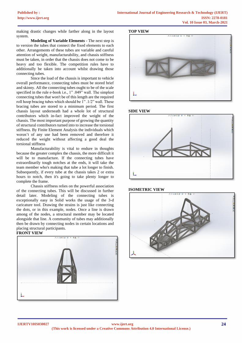
FRONT VIEW
TOP VIEW
SIDE VIEW
ISOMETRIC VIEW

International Journal of Engineering Research & Technology (IJERT)
ISSN: 2278-0181http://www.ijert.org
IJERTV10IS030027(This work is licensed under a Creative Commons Attribution 4.0 International License.)
Published by :
www.ijert.org
Vol. 10 Issue 03, March-2021
25
4. ANALYIS
FRONT IMPACT
REAR IMPACT
SIDE IMPACT
TORSIONAL ANALYSIS
5. CONCLUSION
The purpose of this assignment become to design a
chassis for a competition, a goal that has been completed. In
the work accomplished, a frame is designed that's inflexible
sufficient no longer to deform beneath acceleration and
braking masses and on the same time maintain all the
components together. The work was started out with a
fundamental design of body which would meet the whole
design requirement. Chassis was observed to be secure
appreciably in static (bending) and dynamic (acceleration)
modes with pressure values pretty much less than the yield
power. The dominant characteristic of structural behavior
viz. Torsional rigidity multiplied three instances with a
median boom inside the wall thickness.
The cause of this thesis project is not handiest to
layout the roll cage for the 2019 SUPRA SAEINDA
automobile, however also to offer an intensive study inside
the method taken to arrive on the final layout. With the
general design being cautiously considered beforehand, the
producing manner being managed carefully, and that many
design functions had been established effective within the
performance requirement of the vehicle.
During the design method, the crew should obtain
a compromise among price, manufacturing, overall
performance, and design time in order that their car may be
competitive in all aspects of the SUPRA SAEINDIA
competition. The timeline of the competition, mixed with
the rigorous schedule of college, limits the variety of
iterations for each layout. However, the group ought to take
into account that it'll take several iterations to converge on a
first-class design. The amount of time used for the layout
procedure subtracts from the time to be had for
manufacturing and checking out. Although this paper has
focused on design, it is very critical to check the auto in
order that any design oversights could be highlighted earlier
than opposition.
ACKNOWLEDGEMENT
We would like to thank our faculty Mr.
V. Kondusamy, M.Tech., to give me such an opportunity
to prepare this research paper. I am also grateful to our
college and SUPRA SAE INDIA competition for providing
us with such a platform where we can indulge in this kind of
research work.

International Journal of Engineering Research & Technology (IJERT)
ISSN: 2278-0181http://www.ijert.org
IJERTV10IS030027(This work is licensed under a Creative Commons Attribution 4.0 International License.)
Published by :
www.ijert.org
Vol. 10 Issue 03, March-2021
26
6. REFERENCE [1] https://www.researchgate.net/publication/308277514_Structural_
Performance_Analysis_of_SAE_Supra_Chassis
[2] https://www.researchgate.net/publication/299338429_Design_of_Student_Formula_Race_Car_Chassis
[3] https://www.irjet.net/archives/V7/i5/IRJET-V7I5295.pdf
[4] https://www.iosrjen.org/Papers/Conf.19023-2019/Volume-2/16.%2081-85.pdf
[5] https://www.ijrter.com/papers/volume-3/issue-3/design-of-
chassis-of-student-formula-race-car.pdf [6] https://pdfs.semanticscholar.org/e8e6/3f9725514216cd6b5e97543
1ce417d958b38.pdf
[7] https://www.slideshare.net/PrashantSahgal/design-structural-performance-analysis-of-supra-sae-car-chassis
[8] https://www.ijeat.org/wp-
content/uploads/papers/v7i1/A5219107117.pdf [9] https://journalnx.com/papers/20150193-car-chasis.pdf
[10] https://www.ijser.org/researchpaper/Design-and-Analysis-of-
Suspension-System-with-Different-Material-for-SUPRA-SAE-INDIA-2018.pdf
[11] https://www.scribd.com/document/321690057/81-14-Design
[12] http://users.telenet.be/AudiR8/Chassis%202002-01-
3300Design,%20Analysis%20And%
20Testing%20Of%20A%20Formula%20Sae%20Car%20Chassis.
pdf [13] https://peer.asee.org/two-approaches-to-optimize-formula-sae-
chassis-design-using-finite-element-analysis.pdf
[14] http://www.mate.tue.nl/mate/pdfs/10019.pdf [15] https://www.ijirset.com/upload/2019/october/57_Design_IP.PDF
[16] https://www.sae.org/publications/technical-papers/content/2012-
28-0027/ [17] http://www.ijesi.org/papers/Vol(3)6/Version-1/C0361022033.pdf
[18] https://www.ijert.org/research/analysis-of-formula-student-race-
car-IJERTV5IS100046.pdf [19] SUPRA SAEINDIA 2019 rulebook
[20] Herb Adams, “Chassis Engineering”, Penguin Group (USA) Inc.,
1993, ISBN 1-55788-055-7