Embed Size (px)
Citation preview
DESIGN AND ANALYSIS OF
POLARIZATION RECONFIGURABLE
MICROSTRIP PATCH ANTENNAS
A Thesis submitted with partial fulfillment of Requirements for the degree of
Master of Technology
in
Communication and Networks
by
Ashish Kumar Sahu
Roll No: 213EC5249
Department of Electronics and Communication Engineering
National Institute of Technology Rourkela
Rourkela, Odisha, 769008
May 2015
DESIGN AND ANALYSIS OF
POLARIZATION RECONFIGURABLE
MICROSTRIP PATCH ANTENNAS
A Thesis submitted with partial fulfillment of Requirements for the degree of
Master of Technology
in
Communication and Networks
by
Ashish Kumar Sahu
Roll No: 213EC5249
Under the Guidance of
Dr. Santanu Kumar Behera
Department of Electronics and Communication Engineering
National Institute of Technology Rourkela
Rourkela, Odisha, 769008
May 2015
CERTIFICATE
DEPARTMENT OF ELECTRONICS AND COMMUNICATION
ENGINEERING
NATIONAL INSTITUTE OF TECHNOLOGY, ROURKELA
ROURKELA- 769008, ODISHA, INDIA
This is to certify that the work in this thesis entitled “DESIGN AND ANALYSIS OF
POLARIZATION RECONFIGURABLE MICROSTRIP PATCH ANTENNAS” by Mr.
ASHISH KUMAR SAHU is a record of an original research work carried out by his during
2014-2015 under my supervision and guidance in partial fulfilment of the requirement for the
award of the degree of Master of Technology in Electronics and Communication Engineering
(Communication and Networks), National Institute of Technology, Rourkela. Neither this
thesis nor any part of it, to the best of my knowledge, has been submitted for any degree or
diploma elsewhere.
Place: NIT Rourkela
Date: 19th
May 2015
Dr. Santanu Kumar Behera
Associate Professor

Declaration
I certify that
a) The work comprised in the thesis is original and is done by myself under the
supervision of my supervisor.
b) The work has not been submitted to any other institute for any degree or
diploma.
c) I have followed the guidelines provided by the Institute in writing the thesis.
d) Whenever I have used materials (data, theoretical analysis, and text) from other
sources, I have given due credit to them in the text of the thesis and giving their
details in the references.
e) Whenever I have quoted written materials from other sources, I have put them
under quotation marks and given due credit to the sources by citing them and
giving required details in the references.
DEPARTMENT OF ELECTRONICS AND COMMUNICATION
ENGINEERING
NATIONAL INSTITUTE OF TECHNOLOGY, ROURKELA
ROURKELA- 769008, ODISHA, INDIA
Ashish Kumar Sahu
Roll No 213EC5249

i
Acknowledgements
The work postured in this thesis is by a wide margin the most considerable fulfillment
in my life and it would be incomprehensible without individuals who asserted me and had
faith in me. Above all else I display my significant veneration and profound respects to my
supervisor Prof. S. K. Behera for excellent direction, directing and steady consolation over
the span of this proposal. A respectable man typified, in genuine frame and soul, I consider it
to my favorable luck to have consociated with him.
I might want to reveal a profound feeling of appreciation to admirable Prof. K. K.
Mahapatra, Head of the Department of Electronics and Communication Engineering for
furnishing us with best facilities and his auspicious recommendations.
My special thanks to Prof. S K. Patra, Prof. S. Meher of Department of Electronics
and Communication Engineering for their steady motivation and support amid my
exploration. I need to thank all other faculty of Department of Electronics and
Communication Engineering for their consistent backing and consolation amid my
examination. My special thanks to Ph.D researcher Biswajit Dvivedy for their help,
participation and support. I might want to thank every one of my companions who made my
voyage at NIT Rourkela a permanent and satisfying background.
At long last, my heartfelt gratitude towards my family for their resolute love and
backing for the duration of my life. They taught me the estimation of diligent work by their
own life sample. They issued me enormous backing amid my stay in NIT Rourkela.
Ashish Kumar Sahu
ii
Abstract
The objective of work is to design and develop Polarization Reconfigurable
Microstrip patch antennas which radiate electromagnetic wave of various orthogonal patterns
i.e. VLP, HLP, LHCP and RHCP. A progression of parametric study was done to get that
how the features of the antenna depends on dimensions and material of geometry. Simulation
of antenna has to be done by using CST microwave studio and HFSS. Antennas of various
geometry have to be simulated and fabricated which radiates various orthogonal patterns of
electromagnetic wave. The first antenna is to design and develop dual feed reconfigurable
circularly polarized microstrip patch antenna feeding with microstrip line. Antenna consists
of metallic square radiating patch with thin rectangular slot and dielectric substrate of
permittivity 4.4. Radiating patch fed by microstrip line feeding. By using switch and two
feedline antenna is capable to radiate RHCP and LHCP. The second antenna is to design and
develop reconfigurable circularly polarized microstrip antenna with single feed line, feeding
with Proximity coupled method. Antenna consists of metallic square ring radiating patch and
two substrates of permittivity 1.06 and 4.4. Due to ring shape of radiating patch antenna is
capable to radiate circularly polarized wave. Antenna is capable to radiate LHCP and RHCP
with the help of proper switching action and reconfigurable feedline. The third design is to
design and develop dual feed Quadri-Polarization States microstrip patch antenna feeding
with microstrip line. Antenna consists of metallic square radiating patch and dielectric
substrate of permittivity 2.65. Out of two feedline one is active and other should be isolated at
a time. With the help of two feedline and 4 diodes antenna is capable to radiate VLP, HLP,
LHCP, RHCP. On the patch two opposite corners are slotted and connect by using two PIN
diodes. Due to slotted corner antenna is capable to radiate circularly polarized wave. The
forth design is to design and develop polarization reconfigurable microstrip antenna with
single feedline, feeding with microstrip line. Antenna consists of circular patch with U-slot at
the center and two PIN diodes to make it as reconfigurable and dielectric substrate of
permittivity 4.4. Antenna is capable to radiate electromagnetic wave of various pattern like
LP, LHCP, RHCP. Various S-parameters, surface current distribution, axial ratio, and
radiation patterns are shown for various antennas. Antennas are capable to radiate various
orthogonal patterns which increase the diversity gain. Therefore, antenna have a features of
multipath effects reduction i.e. reduction of fading and interference and antenna can be used
as polarization diversity array.

iii
Contents
Acknowledgement i
Abstract ii
List of Figures v
List of Tables vii
Chapter 1: Introduction 1
1.1 Overview 1
1.2 Objective 2
1.3 Outline 2
Chapter 2: Parameters of Antenna 4
2.1 Directivity 4
2.2 Gain 4
2.3 Antenna Efficiency 5
2.4 Radiation pattern 5
2.5 Field regions 8
2.6 Antenna Bandwidth 8
Chapter 3: Microstrip Patch Antenna 10
3.1 Introduction 10
3.2 Feeding Methods 12
3.2.1 Microstrip Line Feed 13
3.2.2 Coaxial Probe Feed 14
3.2.3 Aperture-coupled feed 15
3.2.4 Proximity-Coupled Feed 16
3.3 Rectangular Microstrip Patch Antenna 18
3.3.1Transmission-Line Model 18
3.3.1.1Fringing Effects 19
3.3.1.2Effective Length 21
3.3.1.3Resonant frequency 22

iv
3.3.1.4Effective Width 23
3.4 Circular Patch Microstrip Antenna 24
Chapter 4: Polarization of Antenna 27
4.1 Introduction 27
4.2Linear, Circular, and Elliptical Polarization 28
4.2.1 Linear Polarization 29
4.2.2 Circular Polarization 30
4.2.3 Elliptical Polarization 31
4.3Left hand and Right hand Polarization 32
4.4Axial Ratio 33
Chapter 5: Polarization Reconfigurable Antenna 34
5.1 Design1: Dual feed thin slot reconfigurable circularly polarized microstrip patch
antenna feeding with microstrip line 34
5.2 Design 2: Single feed reconfigurable circularly polarized microstrip patch antenna
feeding with Proximity coupled method 40
5.3 Design 3: Dual feed Quadri-Polarization States microstrip patch antenna feeding
with microstrip line 45
5.4 Design 4: Single feed polarization reconfigurable microstrip patch antenna
feeding with microstrip line 50
Chapter 6: Conclusion and Future work 55
References 56

v
Figures
Figure 2.1 Radiation pattern of directional antenna (Horn antenna) 6
Figure 2.2 Omnidirectional antenna patterns 7
Figure:2.3 Field regions of an antenna 8
Figure 2.4 Antenna Bandwidth 9
Figure 3.1 Microstrip Patch Antenna 11
Figure 3.2 Shape of patch of microstrip patch antenna 12
Figure 3.3 Microstrip line feed 13
Figure 3.4 Coaxial probe feed, (a) Top view, (b) Side view 14
Figure 3.5 Aperture-coupled feed 15
Figure 3.6 Proximity-coupled feed technique 16
Figure 3.7 Equivalent circuit diagram of feeding techniques 17
Figure 3.8 Rectangular microstrip patch antenna 18
Figure 3.9 Microstrip line and its electric field line 19
Figure 3.10 Effective dielectric constant 20
Figure 3.11 Effective permittivity (𝑟𝑒𝑓𝑓) versus operating frequency (f) 21
Figure 3.12 Effective length of patch due to fringing 22
Figure 3.13 Circular Patch Microstrip Antenna 24
Figure 4.1 Rotation of a plane of EMW and its polarization 28
Figure 4.2 Linearly Polarized Curve 29
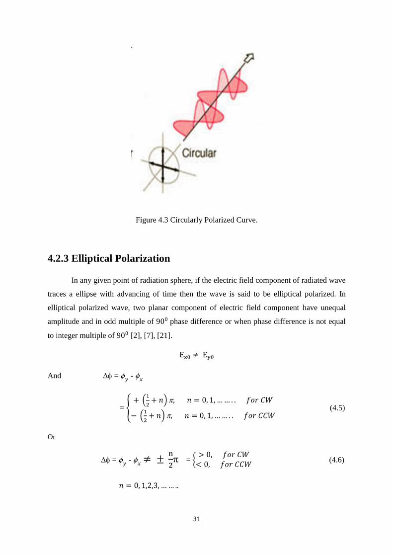
Figure 4.3 Circularly Polarized Curve 31
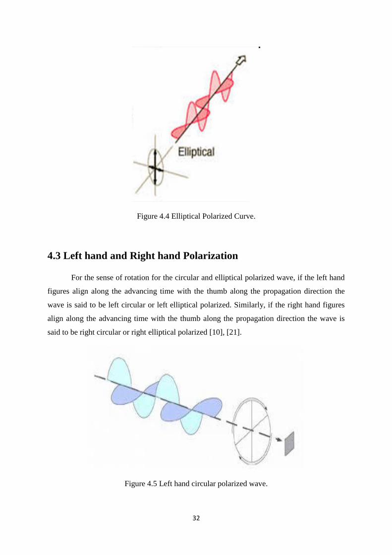
Figure 4.4 Elliptical Polarized Curve 32
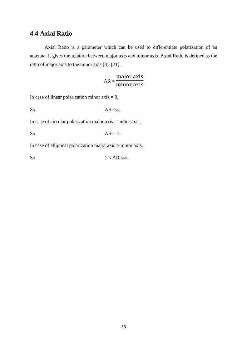
Figure 4.5 Left hand circular polarized wave 32
Figure 5.1 Geometry of proposed antenna (a) LHCP, (b) RHCP 34
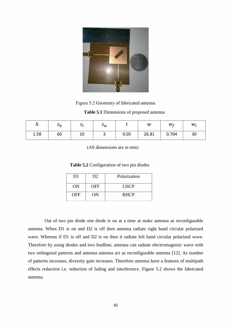
Figure 5.2 Geometry of fabricated antenna 35
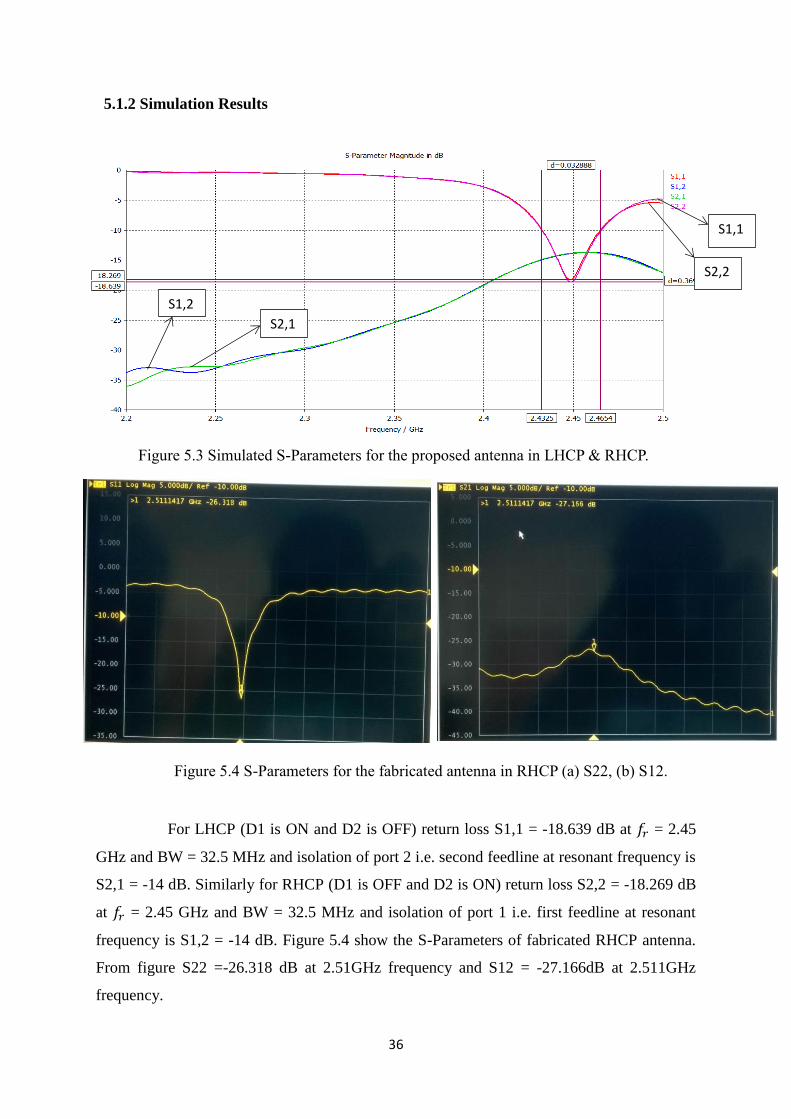
Figure 5.3 Simulated S-Parameters for the proposed antenna in LHCP & RHCP 36
Figure 5.4 S-Parameters for the fabricated antenna in RHCP (a) S22, (b) S12 36
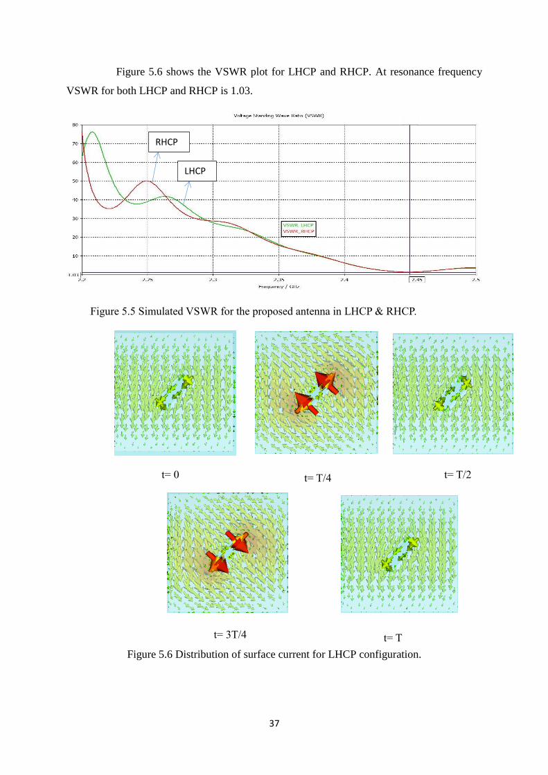
Figure 5.5 Simulated VSWR for the proposed antenna in LHCP & RHCP 37
Figure 5.6 Distribution of surface current for LHCP configuration 37

vi
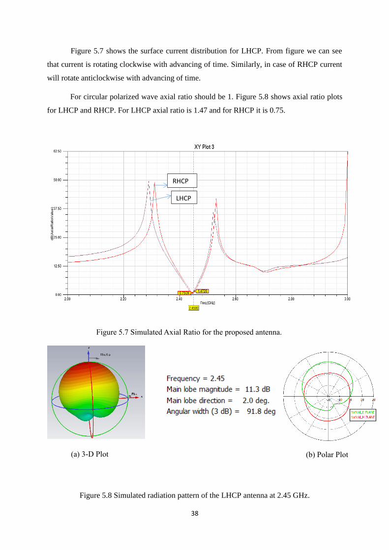
Figure 5.7 Simulated Axial Ratio for the proposed antenna 38
Figure 5.8 Simulated radiation pattern of the LHCP antenna at 2.45 GHz 38
Figure 5.9 Simulated radiation pattern of the RHCP antenna at 2.45 GHz 39
Figure 5.10 Geometry of proposed antenna (a) RHCP, (b) LHCP 40
Figure 5.11 Dimensions of proposed antenna 41
Figure 5.12 S-Parameters for the antenna in LHCP & RHCP 42
Figure 5.13 VSWR for the antenna in LHCP & RHCP 42
Figure 5.14 Axial Ratio plots for LHCP and RHCP 43
Figure 5.15 Radiation pattern of the LHCP antenna at 2.45 GHz 44
Figure 5.16 Radiation pattern of the RHCP antenna at 2.45 GHz 44
Figure 5.17 Geometry of proposed antenna 45
Figure 5.18 Simulated S parameters for the proposed antenna in LHCP & RHCP 46
Figure 5.19 Electric surface current distributions on the RHCP patch antenna 47
Figure 5.20 Simulated Axial Ratio for the proposed antenna 48
Figure 5.21 Simulated radiation pattern of the vertical LP antenna at 5.75 GHz 48
Figure 5.22 Simulated radiation pattern of the horizontal LP antenna at 5.75 GHz 48
Figure 5.23 Simulated radiation pattern of the RHCP antenna at 6.12 GHz 49
Figure 5.24 Simulated radiation pattern of the LHCP antenna at 6.12 GHz 49
Figure 5.25 Geometry of proposed antenna 50
Figure 5.26 S-Parameters for the proposed antenna in LHCP & RHCP 51
Figure 5.27 Electric surface current distributions on the RHCP patch antenna 52
Figure 5.28 Simulated radiation pattern of LHCP antenna at resonant frequency 52
Figure 5.29 Simulated radiation pattern of RHCP antenna at resonant frequency 53
Figure 5.30 Simulated radiation pattern of LP antenna at resonant frequency 53

vii
Tables
Table 3.1 Value of Bessel’s Function 26
Table 5.1 Dimensions of first design 35
Table 5.2 Configuration of two pin diodes of first design 35
Table 5.3 Gain, Directivity and Efficiency of Antenna 39
Table 5.4 Dimensions of second design 41
Table 5.5 Dimensions of third design 45
Table 5.6 Configuration of four pin diodes of third design 46
Table 5.7 Gain and Efficiency of antenna 46
Table 5.8 Dimensions of forth design 50
Table 5.9 Configuration of two pin diodes of forth design 51
Table 5.10 Gain, Directivity and Efficiency of Antenna 54
1
Chapter 1
Introduction
1.1 Overview
Wireless technology is very essential for human life. In most of the electronic
device, wireless system are using. In wireless system, to radiate or receive EMW
(electromagnetic wave) antenna is required. Antenna is very essential element for it. Antenna
is a device which is used to couple the transmitter and receiver section in wireless
communication. At transmitter section, antenna receives the electric power as input and
converts it into the radio wave then radiate into free space. While in receiver section antenna
receive radio wave from free space & convert back into the electric power.
There are such a large number of frameworks that uses antenna, for example, cellular
phones, spacecraft, wireless phones, remote controlled television, radars, etc. Now a days
wireless device demands the compact, small size, light weight, ease of installation. For that
purpose we need antenna low profile. All this requirement can be fulfil by using microstrip
patch antenna. Microstrip antenna is a low profile, light weight, narrow band antenna. It can
easily manufacture by using printed circuit technology which consist of three layers. First
layer is metallic layer in which radiating patch is fabricated by bonding particular shape.
Second layer is dielectric substrate and third layer is metallic layer of ground plane. In some
of microstrip antenna in place of dielectric substrate, dielectric spacers can be used which
increase the bandwidth but coast also increases.
Microstrip antennas are mechanical rugged and low profile antenna and can easily
manufactured on planar and nonplanar surfaces. Microstrip antenna size depends on
operating wavelength generally /2. The size of antenna depends on operating frequency. As
operating frequency increases size of antenna decreases. Therefore in microstrip antenna
operating frequency should be greater than microwave frequency because if frequency is less
size of antenna is very small which have no sense. The use of microstrip patch antenna is
increasing day by day in industrial sector also because of its less expensive, ease of
manufacture i.e. by using printed circuit technology. As increase research in the area of
microstrip patch antenna it can be expect that in future all the conventional antennas can be
replaced by microstrip patch antenna.
2
1.2 Objective
Here we design the microstrip antenna with polarization reconfigurable in
which single antenna act as no of antennas by using the switch. Each antenna radiate different
pattern so it increase the no of patterns and increase the diversity gain.
In many of application of polarization reconfigurable, microstrip antenna is used due to its
low profile properties i.e. light weight, small size, ease of installation, conformability etc.
Antenna diversity, also known as special diversity or space diversity is wireless
diversity scheme that uses number of antennas to improve the reliability and quality of
wireless communication. Polarization reconfigurable antennas have the features of multipath
effects reduction i.e. reduction of fading and interference due to increase in diversity gain.
The shape of the patch of microstrip antenna can be any of rectangular, circular,
square, triangular, rings etc. Each of them has some theoretical design formula. The design of
antenna is inventive where we study the invention of new antenna. By selecting the shape of
antenna we can design reconfigurable antenna in term of polarization, frequency and pattern.
Aim of the work is to study the change of antenna performance with respect to
various parameters of microstrip antenna. Simulation has to be done by using CST MW and
HFSS software.
1.3 Outline
Chapter 1 consist of overview of microstrip antenna, reconfigurable technique and
polarization diversity technique. This chapter also includes the objective of work and outline
of thesis.
Chapter 2 consists of introduction of various parameters of microstrip antenna like gain.
Directivity, radiation pattern, efficiency, bandwidth, field region which depend on antenna
performance.
Chapter 3 consist of basics of microstrip antenna. It includes performance of microstrip
antenna, radiation mechanism, advantage and disadvantage, major applications. Various
feeding techniques are used with advantage and disadvantage of each technique. Most
popular rectangular microstrip antenna discussed with various modelling techniques. Fringing
3
field and its effects on various parameters like length and width of patch and resonant
frequency are discussed. Second most popular microstrip antenna i.e. circular patch antenna
with various design equations are discussed in chapter.
Chapter 4 deals polarization of an antenna and radiating wave. It consist of various
polarization techniques like VLP, HLP, LHCP, RHCP. This chapter deals conditions for
various polarizations with polarization curve.
Chapter 5 explains the design and simulation of polarization reconfigurable antenna of
various geometry. Various switching techniques are shown to switch various polarizations
and to increase no pattern to increase diversity gain. Various simulation results and plots are
explained to increase the performance of antenna. Antennas are simulated by using CST
microwave studio and HFSS software.
Chapter 6 consist of conclusion and future work.
4
Chapter 2
Parameters of Antenna
There are various parameters used antenna and it changes with its application. Performance
and quality of antenna is decided by number of parameters these are Gain, Bandwidth, Directivity,
Efficiency, Aperture effect Radiation pattern etc. These parameters are explained in brief below
2.1 Directivity
Directivity of antenna is the ratio of maximum radiation intensity of test antenna
to the average radiation intensity of test antenna [21], [24]. [26].
𝐷𝑖𝑟𝑒𝑐𝑡𝑖𝑣𝑖𝑡𝑦 =maximum radiation intensity of test antenna
average radiation intensity of test antenna
With respect to isotropic radiator, directivity is defined as the ratio of maximum
radiation intensity of test antenna to the radiation intensity of isotropic antenna i.e.
𝐷𝑖𝑟𝑒𝑐𝑡𝑖𝑣𝑖𝑡𝑦 = maximum radiation intensity of test antenna radiation intensity of isotropic antenna
If antenna is isotropic radiator then directivity is 1. If antenna is transmitting antenna
then directivity in given angle represent the radiation intensity is maximum in that direction.
Whereas, if it is receiving antenna then it shows the power efficiency in particular direction.
2.2 Gain
Gain of the antenna is the ratio of maximum radiation intensity from test antenna to
the radiation intensity from isotropic antenna (lossless) with same power input [21], [24],
[26].
𝐺𝑎𝑖𝑛 =maximum radiation intensity of test antenna
radiation intensity of isotropic (lossless)antenna with same power input
5
For transmitting antenna, it shows the how efficiently it transmit the electromagnetic
wave into free space in given direction with electrical power as input. While in receiving
antenna, it shows the how efficiently it receive electromagnetic wave and convert it into
electrical power.
2.3 Antenna Efficiency
Antenna efficiency is the ratio of radiated power to total input power and it is denoted
by [21], [24], [26].
=Power Radiated
Total Input Power
Relation between gain (G), directivity (D) and efficiency () is
G = . D.
When direction is given then
Directive Gain (,) = . D (,).
2.4 Radiation Patterns
Radiation Pattern is also called as Far-Field Pattern or Antenna Pattern. It is the three
dimensional graphical representation of variation of field strength at particular distance from
antenna. It is a function of direction. In radiating sphere the field strength is not same in all
direction. In some direction it is very high and very less or zero in another direction. The
energy at particular direction in particular distance is measured in term of “field strength”. It
can also be drawn in 2D plane. If azimuth angle is constant then radiation pattern is azimuth
plane pattern, whereas if elevation angle is constant then it is elevation plane pattern. If
radiation is expressed in term of electric field then pattern is called field strength pattern,
whereas if radiation in particular direction is represented in term of power then resulting
pattern is called power pattern [21], [26]. In term of radiation pattern, there are various type
of antenna described below
6
(a) Isotropic antenna:
An antenna which radiate uniformly in all direction is called isotropic antenna. At
particular distance from antenna field strength is same in all direction. It is an ideal and
reference to compare actual antenna and not physically realizable [21], [26].
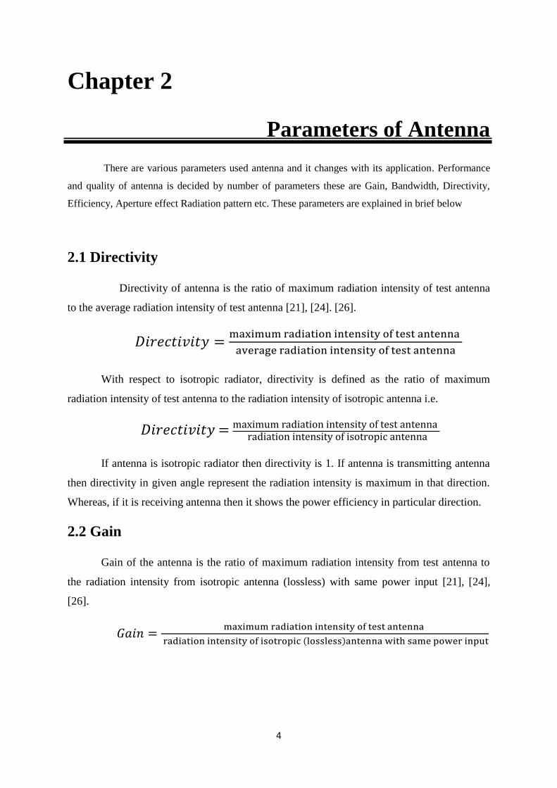
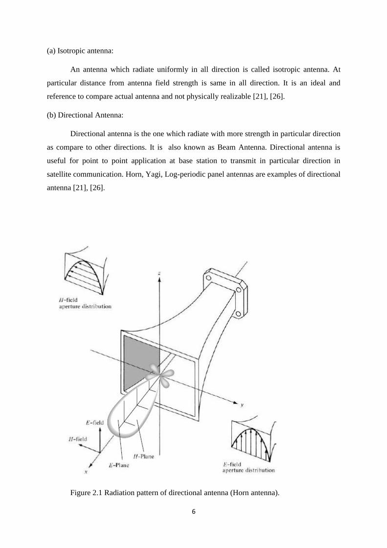
(b) Directional Antenna:
Directional antenna is the one which radiate with more strength in particular direction
as compare to other directions. It is also known as Beam Antenna. Directional antenna is
useful for point to point application at base station to transmit in particular direction in
satellite communication. Horn, Yagi, Log-periodic panel antennas are examples of directional
antenna [21], [26].
Figure 2.1 Radiation pattern of directional antenna (Horn antenna).
7
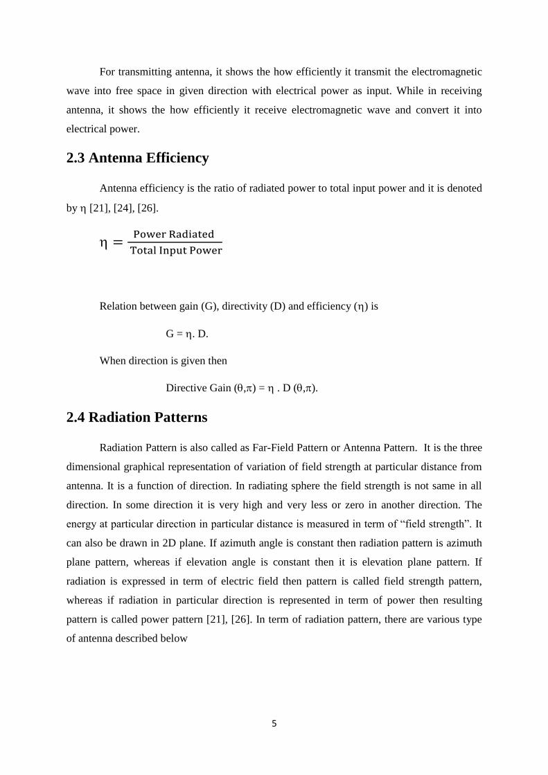
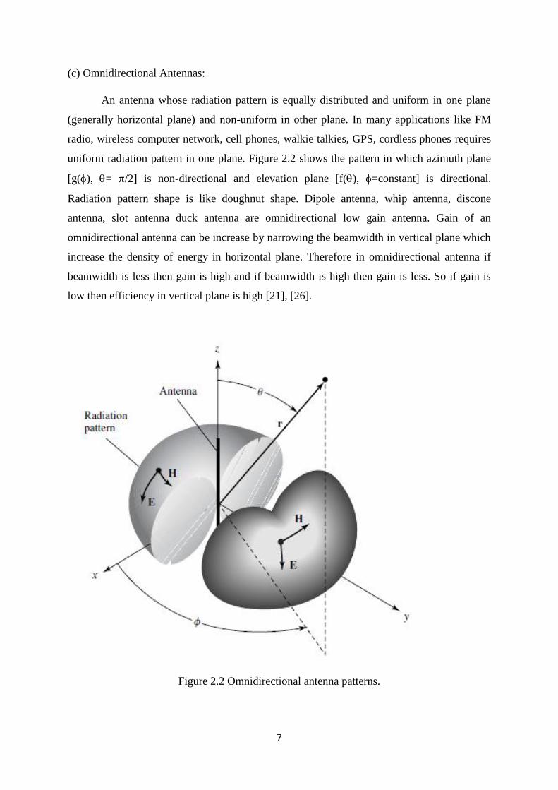
(c) Omnidirectional Antennas:
An antenna whose radiation pattern is equally distributed and uniform in one plane
(generally horizontal plane) and non-uniform in other plane. In many applications like FM
radio, wireless computer network, cell phones, walkie talkies, GPS, cordless phones requires
uniform radiation pattern in one plane. Figure 2.2 shows the pattern in which azimuth plane
[g(), = /2] is non-directional and elevation plane [f(), =constant] is directional.
Radiation pattern shape is like doughnut shape. Dipole antenna, whip antenna, discone
antenna, slot antenna duck antenna are omnidirectional low gain antenna. Gain of an
omnidirectional antenna can be increase by narrowing the beamwidth in vertical plane which
increase the density of energy in horizontal plane. Therefore in omnidirectional antenna if
beamwidth is less then gain is high and if beamwidth is high then gain is less. So if gain is
low then efficiency in vertical plane is high [21], [26].
Figure 2.2 Omnidirectional antenna patterns.
8
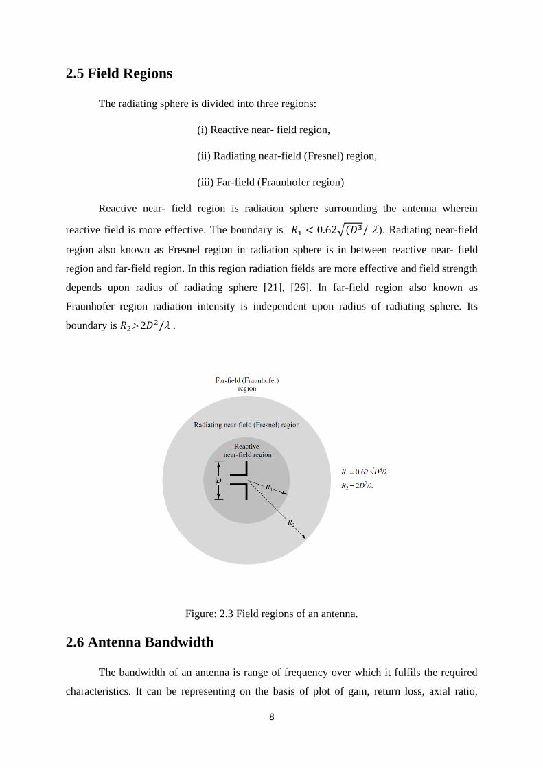
2.5 Field Regions
The radiating sphere is divided into three regions:
(i) Reactive near- field region,
(ii) Radiating near-field (Fresnel) region,
(iii) Far-field (Fraunhofer region)
Reactive near- field region is radiation sphere surrounding the antenna wherein
reactive field is more effective. The boundary is 𝑅1 < 0.62√(𝐷3/ ). Radiating near-field
region also known as Fresnel region in radiation sphere is in between reactive near- field
region and far-field region. In this region radiation fields are more effective and field strength
depends upon radius of radiating sphere [21], [26]. In far-field region also known as
Fraunhofer region radiation intensity is independent upon radius of radiating sphere. Its
boundary is 𝑅2 2𝐷2/ .
Figure: 2.3 Field regions of an antenna.
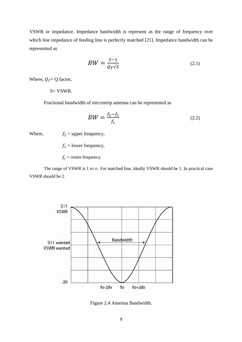
2.6 Antenna Bandwidth
The bandwidth of an antenna is range of frequency over which it fulfils the required
characteristics. It can be representing on the basis of plot of gain, return loss, axial ratio,
9
VSWR or impedance. Impedance bandwidth is represent as the range of frequency over
which line impedance of feeding line is perfectly matched [21]. Impedance bandwidth can be
represented as
𝐵𝑊 =𝑆−1
𝑄𝑇√𝑆 (2.1)
Where, 𝑄𝑇= Q factor,
S= VSWR.
Fractional bandwidth of microstrip antenna can be represented as
𝐵𝑊 =𝑓2−𝑓1
𝑓𝑐 (2.2)
Where, 𝑓2 = upper frequency,
𝑓1 = lower frequency,
𝑓𝑐 = centre frequency.
The range of VSWR is 1 to . For matched line, ideally VSWR should be 1. In practical case
VSWR should be 2.
Figure 2.4 Antenna Bandwidth.
10
Chapter 3
Microstrip Patch Antenna
3.1 Introduction
At the beginning of 19th
century we have used parallel line and coaxial line for
transmission of electromagnetic wave in microwave devices. In the middle of 20th
century
printed circuit board invented allow us to printed circuitry design of transmission lines and it
was very cheap and simple. In printed circuit technology, two wire line act as microstrip line.
Most basic form of microstrip line consists of 3 layers. First layer is metallic radiating patch,
second layer dielectric material and third layer is metallic ground plane. The thought in
transit that microstrip structures can be utilized as radiator for EMW got in 1950s. In 1953
Deschamps presents first time the idea of microstrip patch antenna. A patent of Gutton and
Baissinot was introduced in the year of 1955. After receiving the idea of microstrip antenna
around 20 year practical microstrip radiator was fabricated. At the beginning commercial
microstrip antenna was not available because of poor radiation, high losses, limited existing
in laboratory.
In mobile and wireless communication, where small size light weight, ease of
installation, aero dynamic properties are required, low profile antenna can be used [21].
Currently there are some other aircraft, satellite, spacecraft, and satellite application that
require similar specification. We can use microstrip antenna to get all these requirements
[21]. Microstrip antenna is low profile, comfortable in any surface, low cost, easily
fabricated, robust when attached in rigid surface [14], [15], [21]. By selecting the proper
patch shape, mode of operation, they are flexible in polarization, resonant frequency, and
pattern. By using switch such as pin diode, Varacter diode we can designed reconfigurable
antenna with respect to frequency, polarization, and pattern.
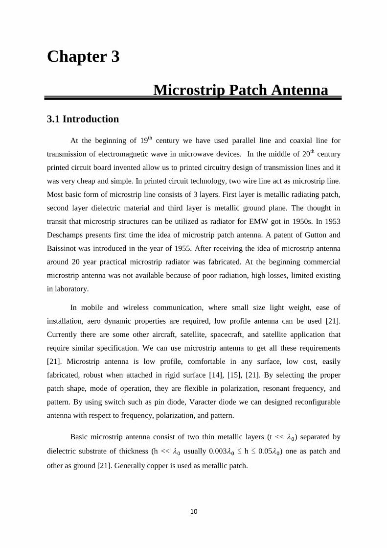
Basic microstrip antenna consist of two thin metallic layers (t << 0) separated by
dielectric substrate of thickness (h << 0 usually 0.0030 ≤ h ≤ 0.050) one as patch and
other as ground [21]. Generally copper is used as metallic patch.
11
Figure 3.1 Microstrip Patch Antenna.
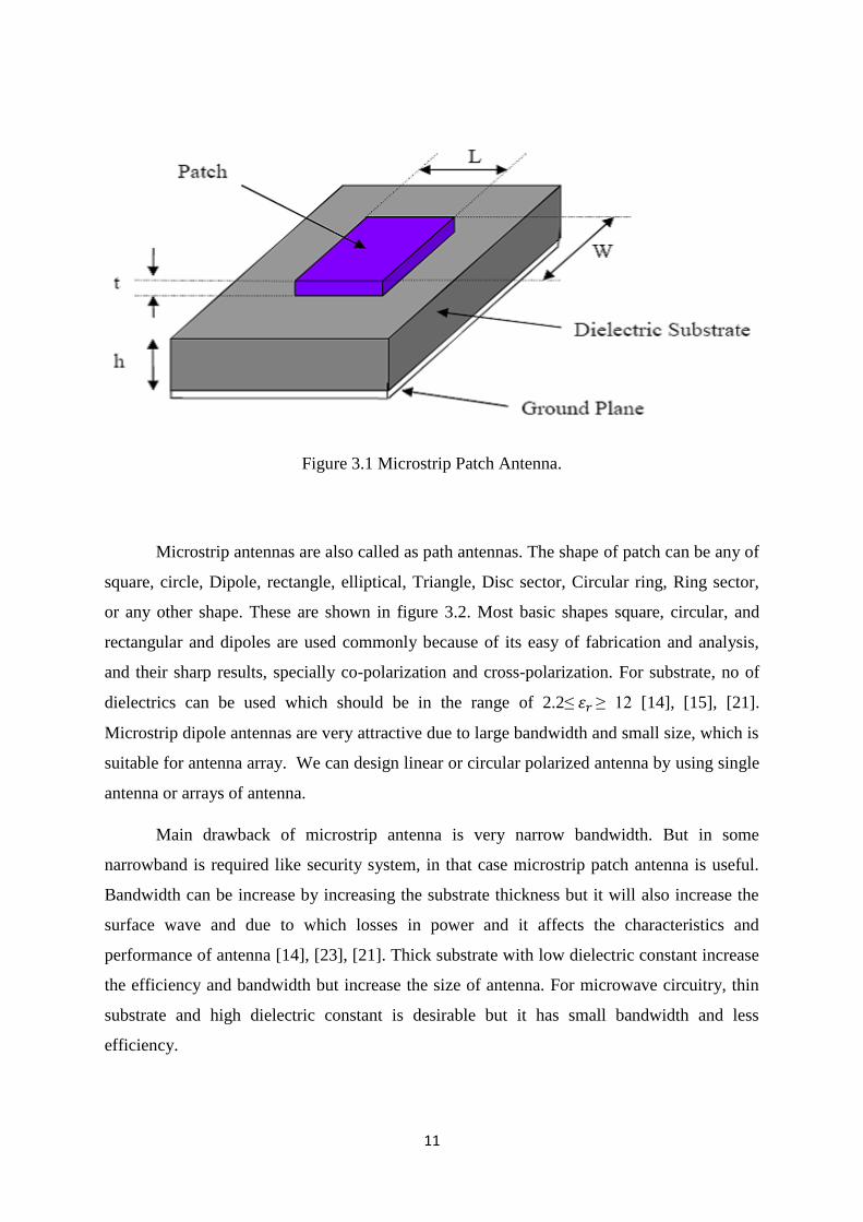
Microstrip antennas are also called as path antennas. The shape of patch can be any of
square, circle, Dipole, rectangle, elliptical, Triangle, Disc sector, Circular ring, Ring sector,
or any other shape. These are shown in figure 3.2. Most basic shapes square, circular, and
rectangular and dipoles are used commonly because of its easy of fabrication and analysis,
and their sharp results, specially co-polarization and cross-polarization. For substrate, no of
dielectrics can be used which should be in the range of 2.2≤ 𝜀𝑟 ≥ 12 [14], [15], [21].
Microstrip dipole antennas are very attractive due to large bandwidth and small size, which is
suitable for antenna array. We can design linear or circular polarized antenna by using single
antenna or arrays of antenna.
Main drawback of microstrip antenna is very narrow bandwidth. But in some
narrowband is required like security system, in that case microstrip patch antenna is useful.
Bandwidth can be increase by increasing the substrate thickness but it will also increase the
surface wave and due to which losses in power and it affects the characteristics and
performance of antenna [14], [23], [21]. Thick substrate with low dielectric constant increase
the efficiency and bandwidth but increase the size of antenna. For microwave circuitry, thin
substrate and high dielectric constant is desirable but it has small bandwidth and less
efficiency.
12
Figure 3.2 Shape of patch of microstrip patch antenna.
Features of antenna not only depends on size of antenna but also depends on input
impedance of antenna and impedance offered by transmission line i.e. impedance matching of
microstrip line and antenna. Generally impedance offered by microstrip patch antenna is
complex and that of transmission line is real (generally 50). Therefore impedance mismatch
and voltage standing wave ratio will introduce and due to which impedance bandwidth will
decrease. To solve this problem, we can use impedance matching network. There are various
impedance matching circuitry are available in circuit theory.
Different methods are presented by researchers like parasitic patch; deserted ground
plane, stacking and bandwidth improvement are interesting topics for research. By selecting
the particular patch shape and mode of operation we can design a patch antenna for particular
radiation pattern, resonant frequency and polarization. By using the switches like MEMS
switch, PIN diode, Varacter diode we can design reconfigurable antenna.
3.2 Feeding Methods
There are large numbers of techniques used to feed microstrip patch antenna [14],
[23], [21].
(a) Microstrip line feed, (b) Coaxial probe feed,
(c) Aperture coupled feed, (d) Proximity-coupled feed.
13
Each method has some advantages and disadvantages. According to requirement
we can choose any one of suitable technique. The main work of feedline is to transfer
electrical power from transmission line to radiating patch. There should be proper impedance
matching between feed line and radiating patch. For impedance matching we need extra
matching circuit. Therefore feedline should be design in such a way that matching circuit
should be design with radiating patch. If we increase the thickness of dielectric substrate, it
will increase bandwidth but also introduce surface wave as well as spurious feed radiation.
Two parameters, spurious feed radiation as well as surface wave depend on the feedline
structure. Spurious feed radiation introduce side lobe in radiation pattern as well as increase
the cross polarisation and surface wave reduce the efficiency of antenna. Out of the above
four feeding techniques, Microstrip line feed and Coaxial probe feed are contacting feeding
technique because feedline directly connected to radiating patch. Whereas Proximity coupled
and Aperture coupled feeding techniques are non-contacting feeding techniques because
feedline mutually coupled to radiating patch. In contacting feeding techniques spurious feed
radiation is more causes compare to non-contacting feeding techniques. So in both microstrip
line feed as well as coaxial feed, introduction of side lobe and generate higher order mode
cause increase cross-polarization are more compare to aperture coupled and proximity
coupled feeding techniques.
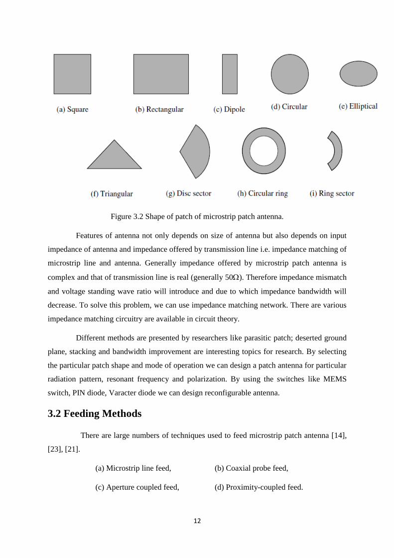
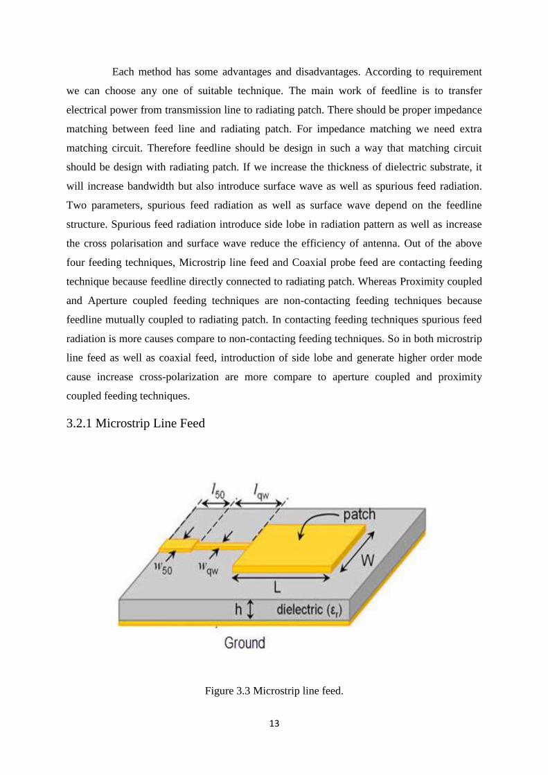
3.2.1 Microstrip Line Feed
Figure 3.3 Microstrip line feed.
14
Microstrip line feed is a metal stripline of thickness equal to radiating patch. Its
width is much less compare to radiating patch. In this method antenna consist of two metal
layers of patch and ground plane on both side of dielectric substrate. This is most basic form
of feeding technique and easy to fabricate. In this method impedance matching is also very
easy by position control only. This technique is contacting technique, so feedline is directly
connected to patch [20], [21], [22]. Therefore it introduce more surface wave and higher
order mode causes cross-polarization. Its bandwidth is also very less about 2-5%.
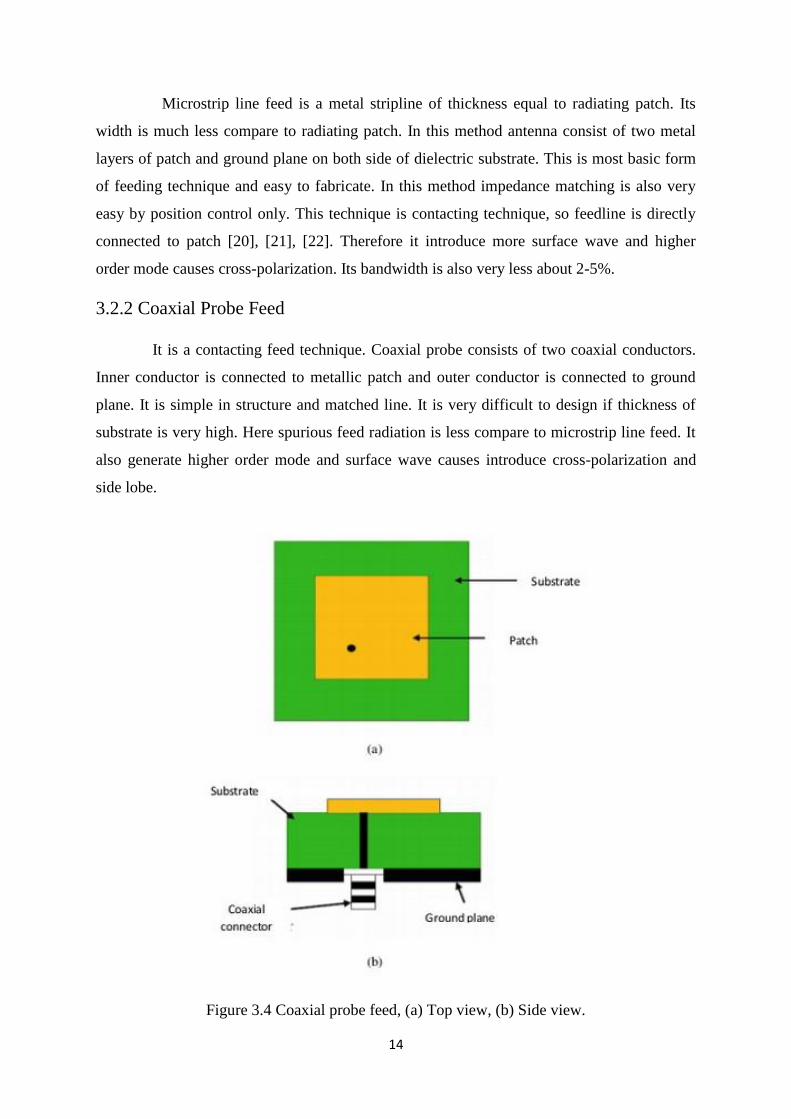
3.2.2 Coaxial Probe Feed
It is a contacting feed technique. Coaxial probe consists of two coaxial conductors.
Inner conductor is connected to metallic patch and outer conductor is connected to ground
plane. It is simple in structure and matched line. It is very difficult to design if thickness of
substrate is very high. Here spurious feed radiation is less compare to microstrip line feed. It
also generate higher order mode and surface wave causes introduce cross-polarization and
side lobe.
Figure 3.4 Coaxial probe feed, (a) Top view, (b) Side view.
15
Its bandwidth is also very less like microstrip feeding technique [21]. To overcome
problems in contacting feeding techniques, non-contacting feeding techniques are introduced.
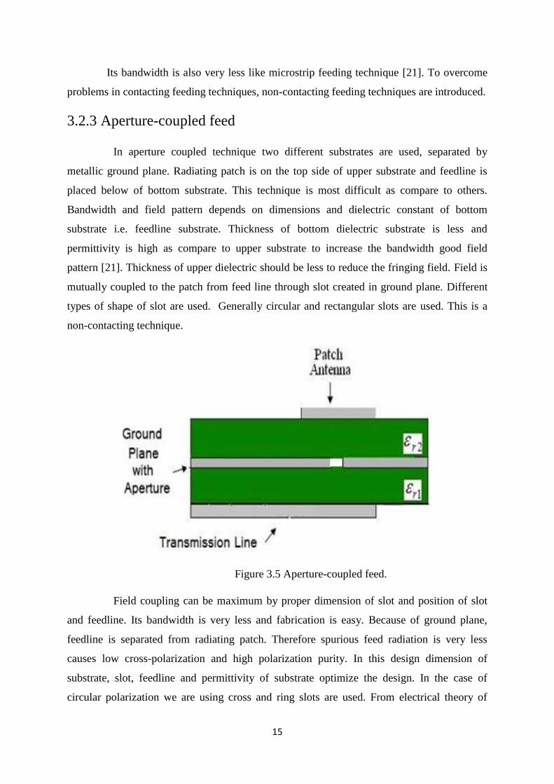
3.2.3 Aperture-coupled feed
In aperture coupled technique two different substrates are used, separated by
metallic ground plane. Radiating patch is on the top side of upper substrate and feedline is
placed below of bottom substrate. This technique is most difficult as compare to others.
Bandwidth and field pattern depends on dimensions and dielectric constant of bottom
substrate i.e. feedline substrate. Thickness of bottom dielectric substrate is less and
permittivity is high as compare to upper substrate to increase the bandwidth good field
pattern [21]. Thickness of upper dielectric should be less to reduce the fringing field. Field is
mutually coupled to the patch from feed line through slot created in ground plane. Different
types of shape of slot are used. Generally circular and rectangular slots are used. This is a
non-contacting technique.
Figure 3.5 Aperture-coupled feed.
Field coupling can be maximum by proper dimension of slot and position of slot
and feedline. Its bandwidth is very less and fabrication is easy. Because of ground plane,
feedline is separated from radiating patch. Therefore spurious feed radiation is very less
causes low cross-polarization and high polarization purity. In this design dimension of
substrate, slot, feedline and permittivity of substrate optimize the design. In the case of
circular polarization we are using cross and ring slots are used. From electrical theory of
16
distribution of voltage and current, at the corner E-field is max and at the centre H-field is
max. If aperture slot is just below the centre of the patch then H-field is max and E-field is
zero [21]. For better impedance matching, feedline length is stretched over slots. The extra
portion of extended feedline acts as open circuit stub. Stub reduces the reactive component of
aperture or slot.
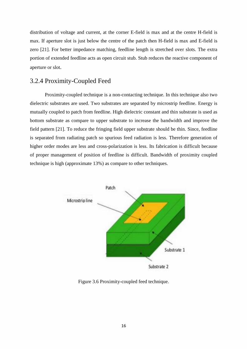
3.2.4 Proximity-Coupled Feed
Proximity-coupled technique is a non-contacting technique. In this technique also two
dielectric substrates are used. Two substrates are separated by microstrip feedline. Energy is
mutually coupled to patch from feedline. High dielectric constant and thin substrate is used as
bottom substrate as compare to upper substrate to increase the bandwidth and improve the
field pattern [21]. To reduce the fringing field upper substrate should be thin. Since, feedline
is separated from radiating patch so spurious feed radiation is less. Therefore generation of
higher order modes are less and cross-polarization is less. Its fabrication is difficult because
of proper management of position of feedline is difficult. Bandwidth of proximity coupled
technique is high (approximate 13%) as compare to other techniques.
Figure 3.6 Proximity-coupled feed technique.
17
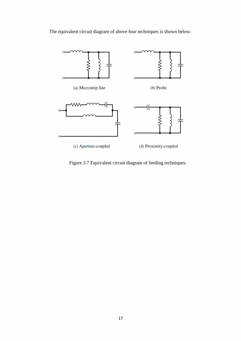
The equivalent circuit diagram of above four techniques is shown below.
Figure 3.7 Equivalent circuit diagram of feeding techniques.
18
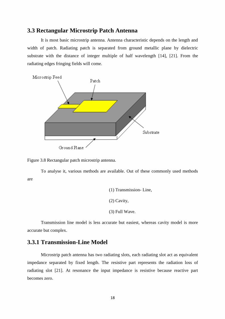
3.3 Rectangular Microstrip Patch Antenna
It is most basic microstrip antenna. Antenna characteristic depends on the length and
width of patch. Radiating patch is separated from ground metallic plane by dielectric
substrate with the distance of integer multiple of half wavelength [14], [21]. From the
radiating edges fringing fields will come.
Figure 3.8 Rectangular patch microstrip antenna.
To analyse it, various methods are available. Out of these commonly used methods
are
(1) Transmission- Line,
(2) Cavity,
(3) Full Wave.
Transmission line model is less accurate but easiest, whereas cavity model is more
accurate but complex.
3.3.1 Transmission-Line Model
Microstrip patch antenna has two radiating slots, each radiating slot act as equivalent
impedance separated by fixed length. The resistive part represents the radiation loss of
radiating slot [21]. At resonance the input impedance is resistive because reactive part
becomes zero.
19
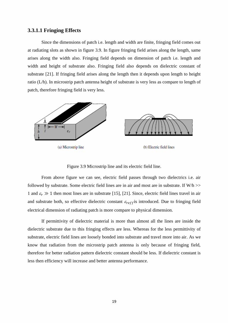
3.3.1.1 Fringing Effects
Since the dimensions of patch i.e. length and width are finite, fringing field comes out
at radiating slots as shown in figure 3.9. In figure fringing field arises along the length, same
arises along the width also. Fringing field depends on dimension of patch i.e. length and
width and height of substrate also. Fringing field also depends on dielectric constant of
substrate [21]. If fringing field arises along the length then it depends upon length to height
ratio (L/h). In microstrip patch antenna height of substrate is very less as compare to length of
patch, therefore fringing field is very less.
Figure 3.9 Microstrip line and its electric field line.
From above figure we can see, electric field passes through two dielectrics i.e. air
followed by substrate. Some electric field lines are in air and most are in substrate. If W/h >>
1 and 𝑟 ≫ 1 then most lines are in substrate [15], [21]. Since, electric field lines travel in air
and substrate both, so effective dielectric constant 𝑟𝑒𝑓𝑓is introduced. Due to fringing field
electrical dimension of radiating patch is more compare to physical dimension.
If permittivity of dielectric material is more than almost all the lines are inside the
dielectric substrate due to this fringing effects are less. Whereas for the less permittivity of
substrate, electric field lines are loosely bonded into substrate and travel more into air. As we
know that radiation from the microstrip patch antenna is only because of fringing field,
therefore for better radiation pattern dielectric constant should be less. If dielectric constant is
less then efficiency will increase and better antenna performance.
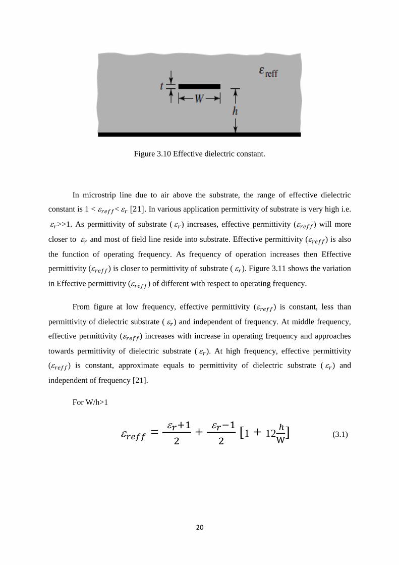
20
Figure 3.10 Effective dielectric constant.
In microstrip line due to air above the substrate, the range of effective dielectric
constant is 1 < 𝑟𝑒𝑓𝑓< 𝑟 [21]. In various application permittivity of substrate is very high i.e.
𝑟>>1. As permittivity of substrate ( 𝑟) increases, effective permittivity (𝑟𝑒𝑓𝑓) will more
closer to 𝑟 and most of field line reside into substrate. Effective permittivity (𝑟𝑒𝑓𝑓) is also
the function of operating frequency. As frequency of operation increases then Effective
permittivity (𝑟𝑒𝑓𝑓) is closer to permittivity of substrate ( 𝑟). Figure 3.11 shows the variation
in Effective permittivity (𝑟𝑒𝑓𝑓) of different with respect to operating frequency.
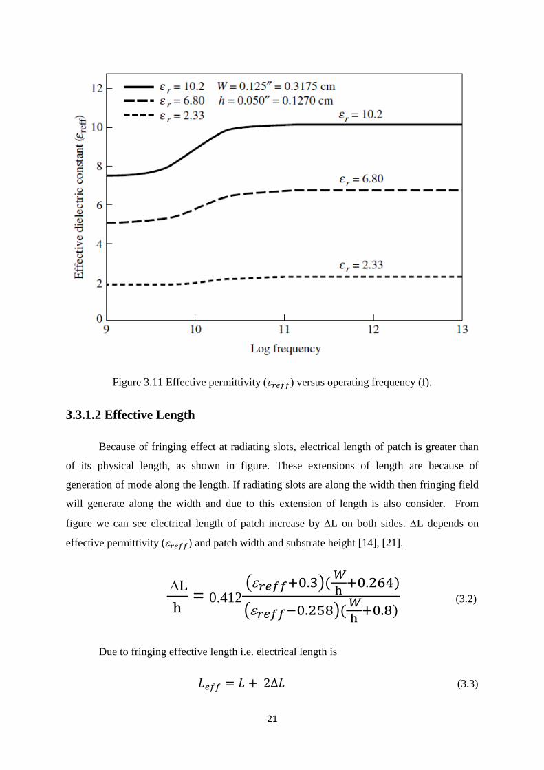
From figure at low frequency, effective permittivity (𝑟𝑒𝑓𝑓) is constant, less than
permittivity of dielectric substrate ( 𝑟) and independent of frequency. At middle frequency,
effective permittivity (𝑟𝑒𝑓𝑓) increases with increase in operating frequency and approaches
towards permittivity of dielectric substrate ( 𝑟). At high frequency, effective permittivity
(𝑟𝑒𝑓𝑓) is constant, approximate equals to permittivity of dielectric substrate ( 𝑟) and
independent of frequency [21].
For W/h>1
𝑟𝑒𝑓𝑓 = 𝑟+1
2 +
𝑟−1
2 [1 + 12
ℎ
W] (3.1)
21
Figure 3.11 Effective permittivity (𝑟𝑒𝑓𝑓) versus operating frequency (f).
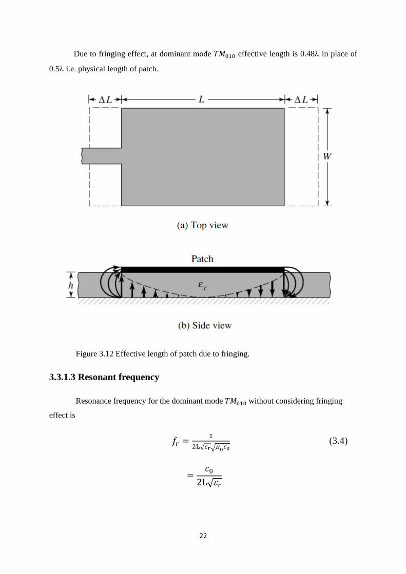
3.3.1.2 Effective Length
Because of fringing effect at radiating slots, electrical length of patch is greater than
of its physical length, as shown in figure. These extensions of length are because of
generation of mode along the length. If radiating slots are along the width then fringing field
will generate along the width and due to this extension of length is also consider. From
figure we can see electrical length of patch increase by L on both sides. L depends on
effective permittivity (𝑟𝑒𝑓𝑓) and patch width and substrate height [14], [21].
L
h = 0.412
(𝑟𝑒𝑓𝑓+0.3)( 𝑊
h+0.264)
(𝑟𝑒𝑓𝑓−0.258)( 𝑊
h+0.8)
(3.2)
Due to fringing effective length i.e. electrical length is
𝐿𝑒𝑓𝑓 = 𝐿 + 2∆𝐿 (3.3)
22
Due to fringing effect, at dominant mode 𝑇𝑀010 effective length is 0.48 in place of
0.5 i.e. physical length of patch.
Figure 3.12 Effective length of patch due to fringing.
3.3.1.3 Resonant frequency
Resonance frequency for the dominant mode 𝑇𝑀010 without considering fringing
effect is
𝑓𝑟 =1
2L√𝑟√00 (3.4)
=𝑐0
2L√𝑟
23
From above equation, we can see resonance frequency depends on length of
patch and length depends on fringing fields. Therefore resonance frequency also depends on
fringing field [21].
𝑓𝑟𝑐 =1
2𝐿𝑒𝑓𝑓√𝑟𝑒𝑓𝑓√00
=1
2(L + 2L )√𝑟𝑒𝑓𝑓√00
= q1
2L√𝑟√00
= q𝑐0
2L√𝑟 (3.5)
Where,
q =𝑓𝑟𝑐
𝑓𝑟
q= fringing factor also known as length reduction factor.
Fringing field increase with the height of the substrate, as a result distance between
radiating edges increase and resonant frequency decrease [21], [23].
3.3.1.4 Effective Width
In dominant mode 𝑇𝑀010, there is no fringing field along the width so effective
permittivity (𝑟𝑒𝑓𝑓) is equal to permittivity of dielectric substrate (𝑟) [21].
𝑟𝑒𝑓𝑓 = 𝑟
Therefore in formula for width we will consider 𝑟 in place of 𝑟𝑒𝑓𝑓 and it is
𝑊 = 1
2𝑓𝑟√0𝜀0 √
2
𝑟+1
24
=𝑐0
2𝑓𝑟 √
2
𝑟+1 (3.6)
Where, 𝑐0 is the velocity of light in free space.
Design:
Based on the above simplified formula we can easily design the rectangular microstrip
patch antenna by using following steps [21]
(a) Specify: 𝑟, h, and 𝑓𝑟
(b) Calculate W and L
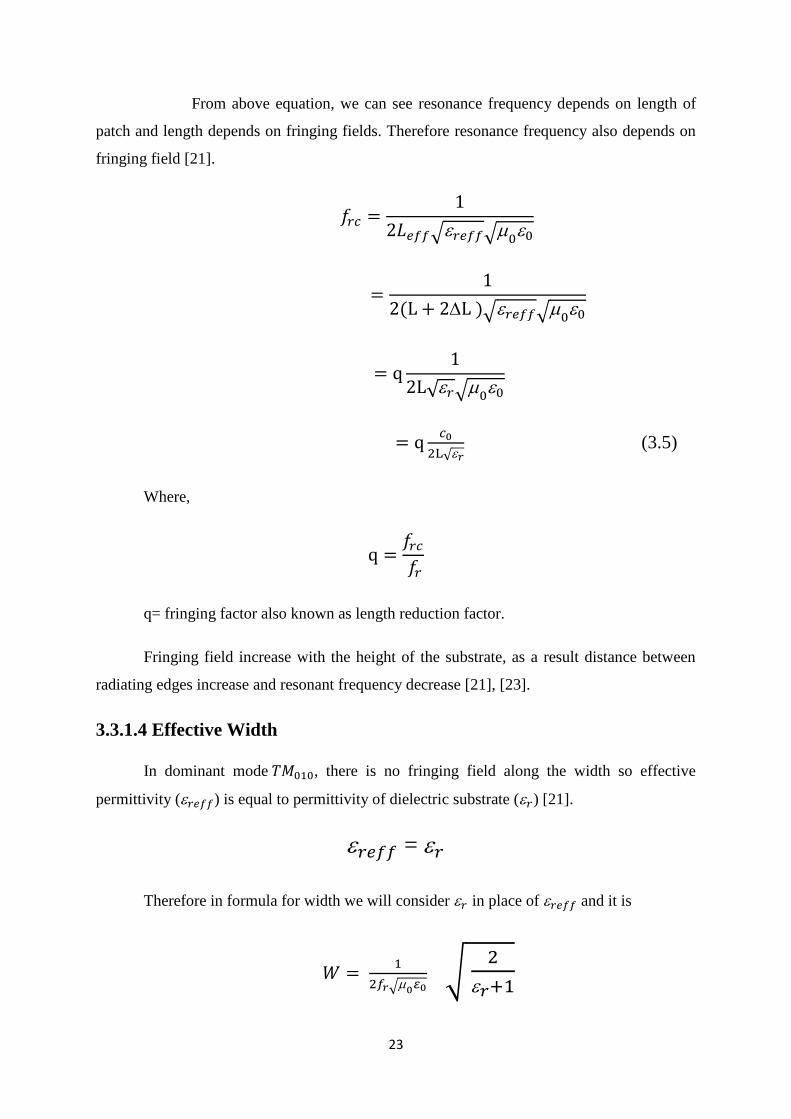
3.4 Circular Patch Microstrip Antenna
Circular patch is also commonly used like rectangular patch in microstrip antenna. As
we have seen two parameters, length and width of rectangular patch antenna calculated to
study the various parameters of antenna, similarly in circular to study the performance of
antenna, we need to calculate only radius of patch [21]. The schematic diagram of circular
patch microstrip antenna is shown below
Figure 3.13 Circular Patch Microstrip Antenna.
25
From above figure we can see that antenna consist of three layers. First layer is
metallic circular patch, second layer is dielectric substrate and third layer is metallic ground
plane. Here, feeding mechanism is coaxial feeding. Metallic patch is fed at a point of distance
‘r’ from centre and angle ‘’ from x-axis. Analysis can be done by assuming cavity having
two metallic walls (metallic patch and metallic ground plane) and edges are acting as
magnetic walls. The E-field component of radiating wave is
𝐸𝑧 = 𝐸0𝐽𝑛(𝑘𝑟)cos (𝑛) (3.7)
Similarly, H-field component is
𝐻𝑟 = −jn
𝑘2𝑟𝐸0𝐽𝑛(𝑘𝑟)sin (𝑛) (3.8)
𝐻 = −j
𝑘𝐸0𝑗𝑛
′(𝑘𝑟)cos (𝑛) (3.9)
Where,
𝐽𝑛 is Bessel’s function of order ‘n’,
𝑗𝑛′ is derivative of Bessel’s function of order ‘n’,
k is propagation constant.
For 𝑇𝑀𝑚𝑛 mode, resonant frequency is
𝑓𝑚𝑛 = 𝑋𝑚𝑛𝑐
2𝑒𝑓𝑓√𝑟 (3.11)
Where,
𝑋𝑚𝑛 is the zeroes of Bessel’s function derivative of order ‘n’
and c represents the light velocity in free space.
Radius of patch can be calculated by

26
𝑎 = 𝑋𝑚𝑛𝑐
2√𝑟 [1 +
2ℎ
𝑎𝑟 (ln {
𝑎
2𝑓𝑚𝑛ℎ} + 1.7726)]
−1/2 (3.12)
Similarly, for 𝑎 /h >> 1, effective radius of patch can be calculated as
𝑎𝑒𝑓𝑓 = 𝑎 [1 + 2ℎ
𝑎𝑟 (ln {
𝑎
2ℎ} + 1.7726)]
−1/2 (3.13)
Table 3.1 Bessel’s Function value
Zeroes of Bessel’s function derivative of order ‘n’ for different modes [21] are
𝑇𝑀𝑚𝑛 1,1 2,1 0,2 3,1
𝑋𝑚𝑛 1.84118 3.05424 3.83171 4.20119
27
Chapter 4
Polarization of Antenna
4.1 Introduction
Polarization of an antenna can be defined like polarization of electromagnetic wave in
given direction of radiation. If direction is not given then we consider in the maximum gain
direction. Polarization of radiated electromagnetic wave can be change by changing the
points in the radiating sphere i.e. polarization can be change by changing with direction from
antenna [21]. Therefore in pattern, at different part polarization is also different.
Polarization is the study of relative orientation of two planar component of electric
field component of radiated electromagnetic wave. Another way, we can define as the
polarization is the orientation of magnitude of electric field with direction. Here the direction
is the time varying direction. Therefore, we can say polarization is a function of time,
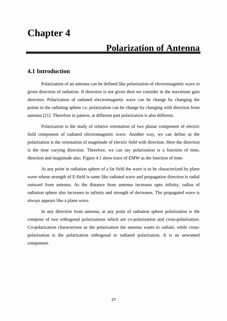
direction and magnitude also. Figure 4.1 show trace of EMW as the function of time.
At any point in radiation sphere of a far field the wave is to be characterized by plane
wave whose strength of E-field is same like radiated wave and propagation direction is radial
outward from antenna. As the distance from antenna increases upto infinity, radius of
radiation sphere also increases to infinity and strength of decreases. The propagated wave is
always appears like a plane wave.
In any direction from antenna, at any point of radiation sphere polarization is the
compose of two orthogonal polarizations which are co-polarization and cross-polarization.
Co-polarization characterizes as the polarization the antenna wants to radiate, while cross-
polarization is the polarization orthogonal to radiated polarization. It is an unwanted
component.
28
Figure 4.1 Rotation of a plane of EMW and its polarization.
4.2Linear, Circular, and Elliptical Polarization
Polarization of radiated wave can be classified as Linear, Circular and Elliptical
Polarization. Electric field component of a plane wave propagating towards negative z
direction can be represented [1], [21] as
29
E(z; t) = E𝑥(z; t) ˆ xa + E𝑦(z; t) ˆ ya (4.1)
Where,
E𝑥(z; t) = Re [Ex 𝑒−𝑗(𝑤𝑡+𝑘𝑧)]
= Re [Ex0 𝑒−𝑗(𝑤𝑡+𝑘𝑧+ 𝑥)] (4.2)
And E𝑦(z; t) = Re [Ey 𝑒−𝑗(𝑤𝑡+𝑘𝑧)]
=Re [Ey0 𝑒−𝑗(𝑤𝑡+𝑘𝑧+ 𝑦)
] (4.3)
Where, Ex0 and Ey0 are maximum amplitude of x and y component of electric field
component.
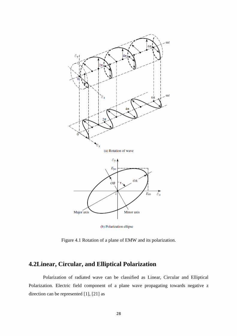
4.2.1 Linear Polarization
In linear polarized wave, two planar component of electric field component of equal
or unequal amplitude are in phase [4], [5], [21].
= 𝑦
- 𝑥 = n, n= 0, 1, 2, …….
Figure 4.2 Linearly Polarized Curve.
In case of linear polarization, if out of the two planar component of electric field of
radiated wave only vertical component exist and there is no any horizontal component i.e.
30
Ex0 = 0
Then polarization is called vertical linear polarization. In this case polarization curve
is along y-axis only.
Similarly, if there is only horizontal component exist and there is no any vertical
component i.e.
Ey0 = 0
Then polarization is called horizontal polarization. In this case polarization curve is
along x-axis only.
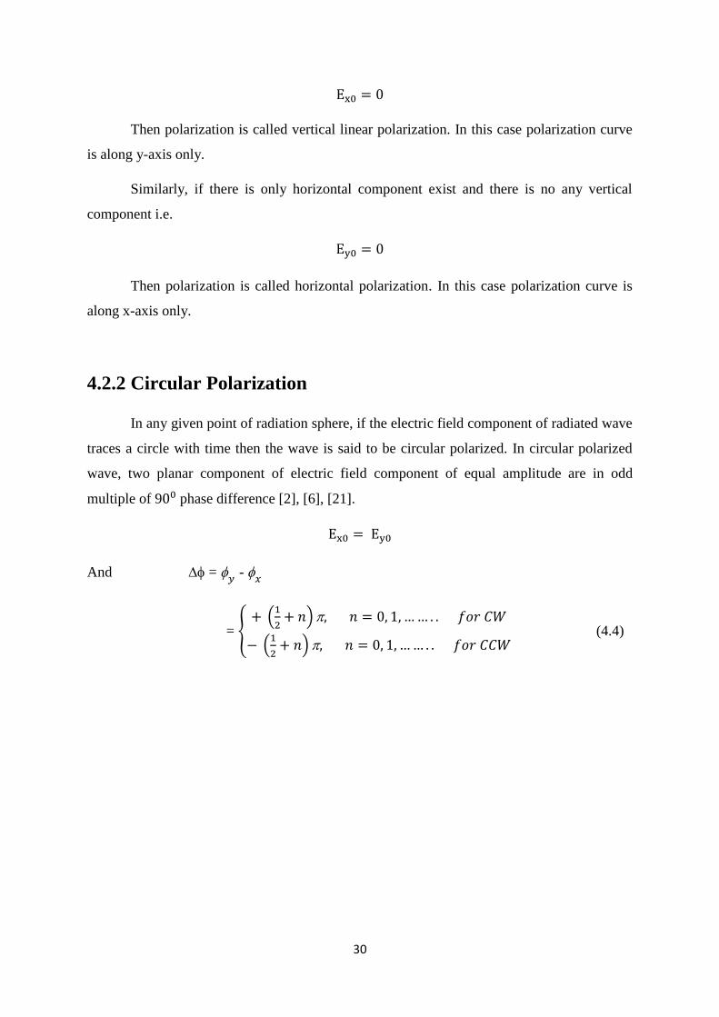
4.2.2 Circular Polarization
In any given point of radiation sphere, if the electric field component of radiated wave
traces a circle with time then the wave is said to be circular polarized. In circular polarized
wave, two planar component of electric field component of equal amplitude are in odd
multiple of 900 phase difference [2], [6], [21].
Ex0 = Ey0
And = 𝑦
- 𝑥
= {+ (
1
2+ 𝑛) , 𝑛 = 0, 1, … … . . 𝑓𝑜𝑟 𝐶𝑊
− (1
2+ 𝑛) , 𝑛 = 0, 1, … … . . 𝑓𝑜𝑟 𝐶𝐶𝑊
(4.4)
31
Figure 4.3 Circularly Polarized Curve.
4.2.3 Elliptical Polarization
In any given point of radiation sphere, if the electric field component of radiated wave
traces a ellipse with advancing of time then the wave is said to be elliptical polarized. In
elliptical polarized wave, two planar component of electric field component have unequal
amplitude and in odd multiple of 900 phase difference or when phase difference is not equal
to integer multiple of 900 [2], [7], [21].
Ex0 ≠ Ey0
And = 𝑦
- 𝑥
= {+ (
1
2+ 𝑛) , 𝑛 = 0, 1, … … . . 𝑓𝑜𝑟 𝐶𝑊
− (1
2+ 𝑛) , 𝑛 = 0, 1, … … . . 𝑓𝑜𝑟 𝐶𝐶𝑊
(4.5)
Or
= 𝑦
- 𝑥 ≠ ±
n
2 = {
> 0, 𝑓𝑜𝑟 𝐶𝑊< 0, 𝑓𝑜𝑟 𝐶𝐶𝑊
(4.6)
𝑛 = 0, 1,2,3, … … ..
32
Figure 4.4 Elliptical Polarized Curve.
4.3 Left hand and Right hand Polarization
For the sense of rotation for the circular and elliptical polarized wave, if the left hand
figures align along the advancing time with the thumb along the propagation direction the
wave is said to be left circular or left elliptical polarized. Similarly, if the right hand figures
align along the advancing time with the thumb along the propagation direction the wave is
said to be right circular or right elliptical polarized [10], [21].
Figure 4.5 Left hand circular polarized wave.
33
4.4 Axial Ratio
Axial Ratio is a parameter which can be used to differentiate polarization of an
antenna. It gives the relation between major axis and minor axis. Axial Ratio is defined as the
ratio of major axis to the minor axis [8], [21].
AR = major axis
minor axis
In case of linear polarization minor axis = 0,
So AR =.
In case of circular polarization major axis = minor axis,
So AR = 1.
In case of elliptical polarization major axis > minor axis,
So 1 < AR <.
34
Chapter 5
Polarization Reconfigurable Antenna
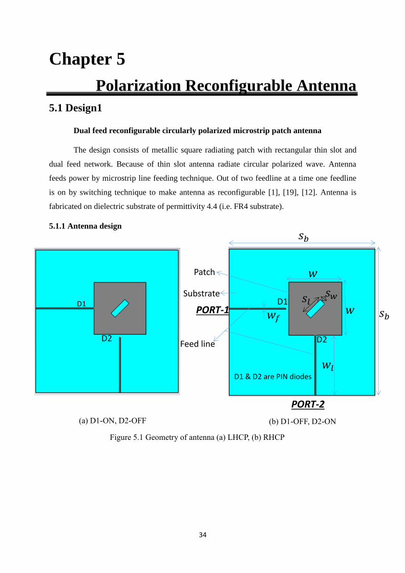
5.1 Design1
Dual feed reconfigurable circularly polarized microstrip patch antenna
The design consists of metallic square radiating patch with rectangular thin slot and
dual feed network. Because of thin slot antenna radiate circular polarized wave. Antenna
feeds power by microstrip line feeding technique. Out of two feedline at a time one feedline
is on by switching technique to make antenna as reconfigurable [1], [19], [12]. Antenna is
fabricated on dielectric substrate of permittivity 4.4 (i.e. FR4 substrate).
5.1.1 Antenna design
(a) D1-ON, D2-OFF (b) D1-OFF, D2-ON
D1
D2
D1
D2
Patch
Substrate
Feed line
D1 & D2 are PIN diodes
PORT-2
PORT-1
𝑠𝑏
𝑠𝑏
𝑤
𝑤 𝑤𝑓
𝑤𝑙
𝑠𝑙 𝑠𝑤
Figure 5.1 Geometry of antenna (a) LHCP, (b) RHCP
35
Table 5.1 Dimensions of proposed antenna
ℎ 𝑠𝑏 𝑠𝑙 𝑠𝑤 𝑡 𝑤 𝑤𝑓 𝑤𝑙
1.58 60 10 3 0.05 26.81 0.704 30
Table 5.2 Configuration of two pin diodes
Out of two pin diode one diode is on at a time at make antenna as reconfigurable
antenna. When D1 is on and D2 is off then antenna radiate right hand circular polarized
wave. Whereas if D1 is off and D2 is on then it radiate left hand circular polarized wave.
Therefore by using diodes and two feedline, antenna can radiate electromagnetic wave with
two orthogonal patterns and antenna antenna act as reconfigurable antenna [12]. As number
of patterns increases, diversity gain increases. Therefore antenna have a features of multipath
effects reduction i.e. reduction of fading and interference. Figure 5.2 shows the fabricated
antenna.
D1 D2 Polarization
ON OFF LHCP
OFF ON RHCP
(All dimensions are in mm)
Figure 5.2 Geometry of fabricated antenna
36
5.1.2 Simulation Results
For LHCP (D1 is ON and D2 is OFF) return loss S1,1 = -18.639 dB at 𝑓𝑟 = 2.45
GHz and BW = 32.5 MHz and isolation of port 2 i.e. second feedline at resonant frequency is
S2,1 = -14 dB. Similarly for RHCP (D1 is OFF and D2 is ON) return loss S2,2 = -18.269 dB
at 𝑓𝑟 = 2.45 GHz and BW = 32.5 MHz and isolation of port 1 i.e. first feedline at resonant
frequency is S1,2 = -14 dB. Figure 5.4 show the S-Parameters of fabricated RHCP antenna.
From figure S22 =-26.318 dB at 2.51GHz frequency and S12 = -27.166dB at 2.511GHz
frequency.
Figure 5.2 Simulated S parameters for the proposed antenna in LHCP & RHCP.
S1,2
S2,1
S1,1
S2,2
Figure 5.3 Simulated S-Parameters for the proposed antenna in LHCP & RHCP.
Figure 5.4 S-Parameters for the fabricated antenna in RHCP (a) S22, (b) S12.
37
Figure 5.6 shows the VSWR plot for LHCP and RHCP. At resonance frequency
VSWR for both LHCP and RHCP is 1.03.
Figure 5.6 Distribution of surface current for LHCP configuration.
RHCP
LHCP
Figure 5.5 Simulated VSWR for the proposed antenna in LHCP & RHCP.
t= 0 t= T/4 t= T/2
t= 3T/4 t= T
38
Figure 5.7 shows the surface current distribution for LHCP. From figure we can see
that current is rotating clockwise with advancing of time. Similarly, in case of RHCP current
will rotate anticlockwise with advancing of time.
For circular polarized wave axial ratio should be 1. Figure 5.8 shows axial ratio plots
for LHCP and RHCP. For LHCP axial ratio is 1.47 and for RHCP it is 0.75.
Figure 5.8 Simulated radiation pattern of the LHCP antenna at 2.45 GHz.
Figure 5.7 Simulated Axial Ratio for the proposed antenna.
RHCP
LHCP
(a) 3-D Plot (b) Polar Plot
39
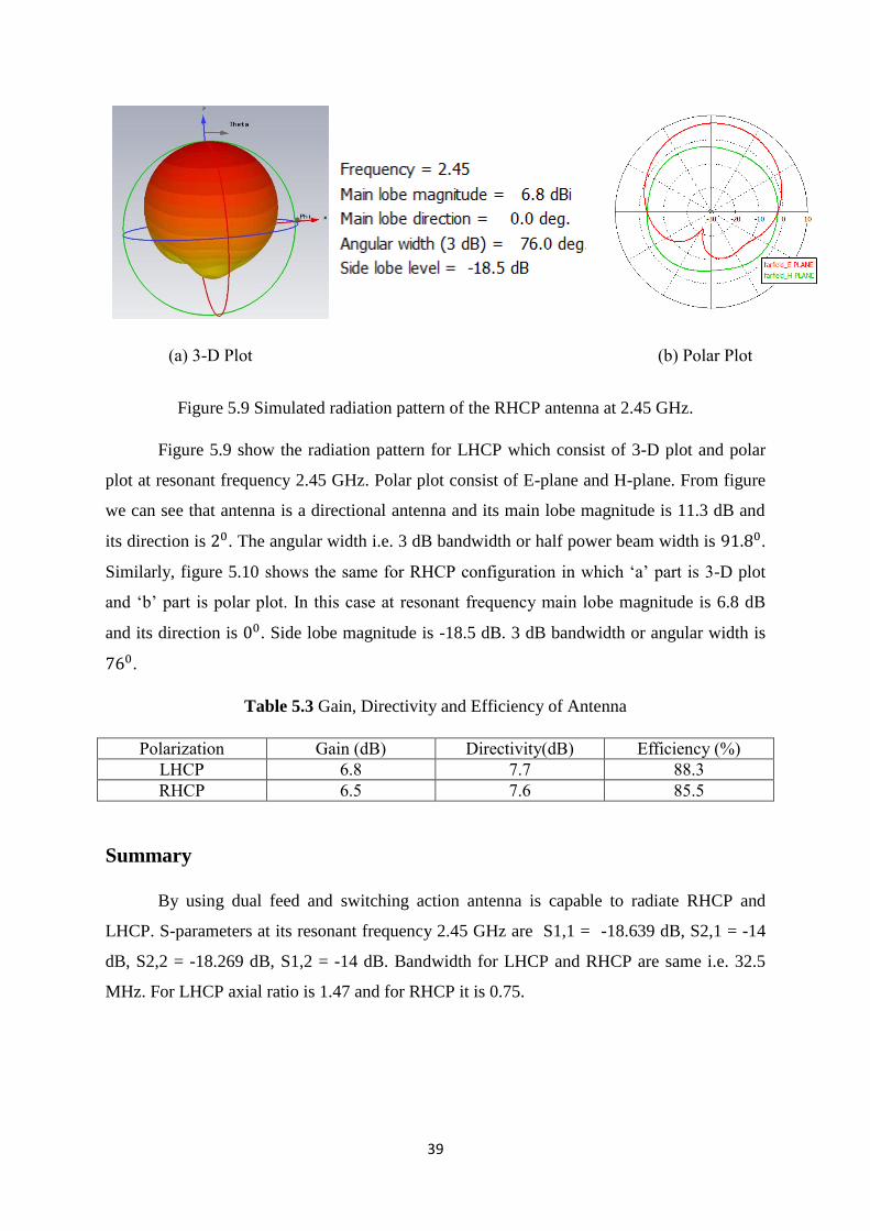
Figure 5.9 Simulated radiation pattern of the RHCP antenna at 2.45 GHz.
Figure 5.9 show the radiation pattern for LHCP which consist of 3-D plot and polar
plot at resonant frequency 2.45 GHz. Polar plot consist of E-plane and H-plane. From figure
we can see that antenna is a directional antenna and its main lobe magnitude is 11.3 dB and
its direction is 20. The angular width i.e. 3 dB bandwidth or half power beam width is 91.80.
Similarly, figure 5.10 shows the same for RHCP configuration in which ‘a’ part is 3-D plot
and ‘b’ part is polar plot. In this case at resonant frequency main lobe magnitude is 6.8 dB
and its direction is 00. Side lobe magnitude is -18.5 dB. 3 dB bandwidth or angular width is
760.
Table 5.3 Gain, Directivity and Efficiency of Antenna
Polarization Gain (dB) Directivity(dB) Efficiency (%)
LHCP 6.8 7.7 88.3
RHCP 6.5 7.6 85.5
Summary
By using dual feed and switching action antenna is capable to radiate RHCP and
LHCP. S-parameters at its resonant frequency 2.45 GHz are S1,1 = -18.639 dB, S2,1 = -14
dB, S2,2 = -18.269 dB, S1,2 = -14 dB. Bandwidth for LHCP and RHCP are same i.e. 32.5
MHz. For LHCP axial ratio is 1.47 and for RHCP it is 0.75.
(a) 3-D Plot (b) Polar Plot
40
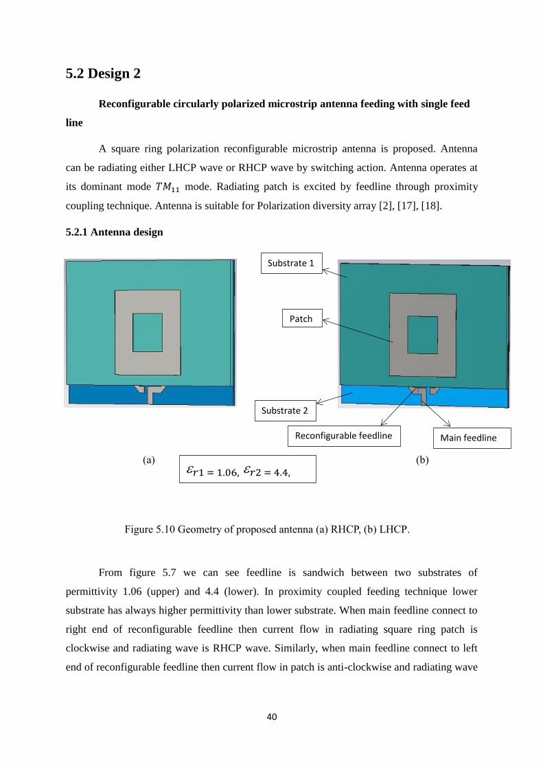
5.2 Design 2
Reconfigurable circularly polarized microstrip antenna feeding with single feed
line
A square ring polarization reconfigurable microstrip antenna is proposed. Antenna
can be radiating either LHCP wave or RHCP wave by switching action. Antenna operates at
its dominant mode 𝑇𝑀11 mode. Radiating patch is excited by feedline through proximity
coupling technique. Antenna is suitable for Polarization diversity array [2], [17], [18].
5.2.1 Antenna design
From figure 5.7 we can see feedline is sandwich between two substrates of
permittivity 1.06 (upper) and 4.4 (lower). In proximity coupled feeding technique lower
substrate has always higher permittivity than lower substrate. When main feedline connect to
right end of reconfigurable feedline then current flow in radiating square ring patch is
clockwise and radiating wave is RHCP wave. Similarly, when main feedline connect to left
end of reconfigurable feedline then current flow in patch is anti-clockwise and radiating wave
Figure 5.10 Geometry of proposed antenna (a) RHCP, (b) LHCP.
(a) (b)
Substrate 1
Patch
Reconfigurable feedline
Substrate 2
𝑟1 = 1.06, 𝑟2 = 4.4,
Main feedline
41
is left hand circularly polarized wave. Therefore we can see here number of pattern increases
and diversity gain increases. So we can use this antenna as polarization diversity array.
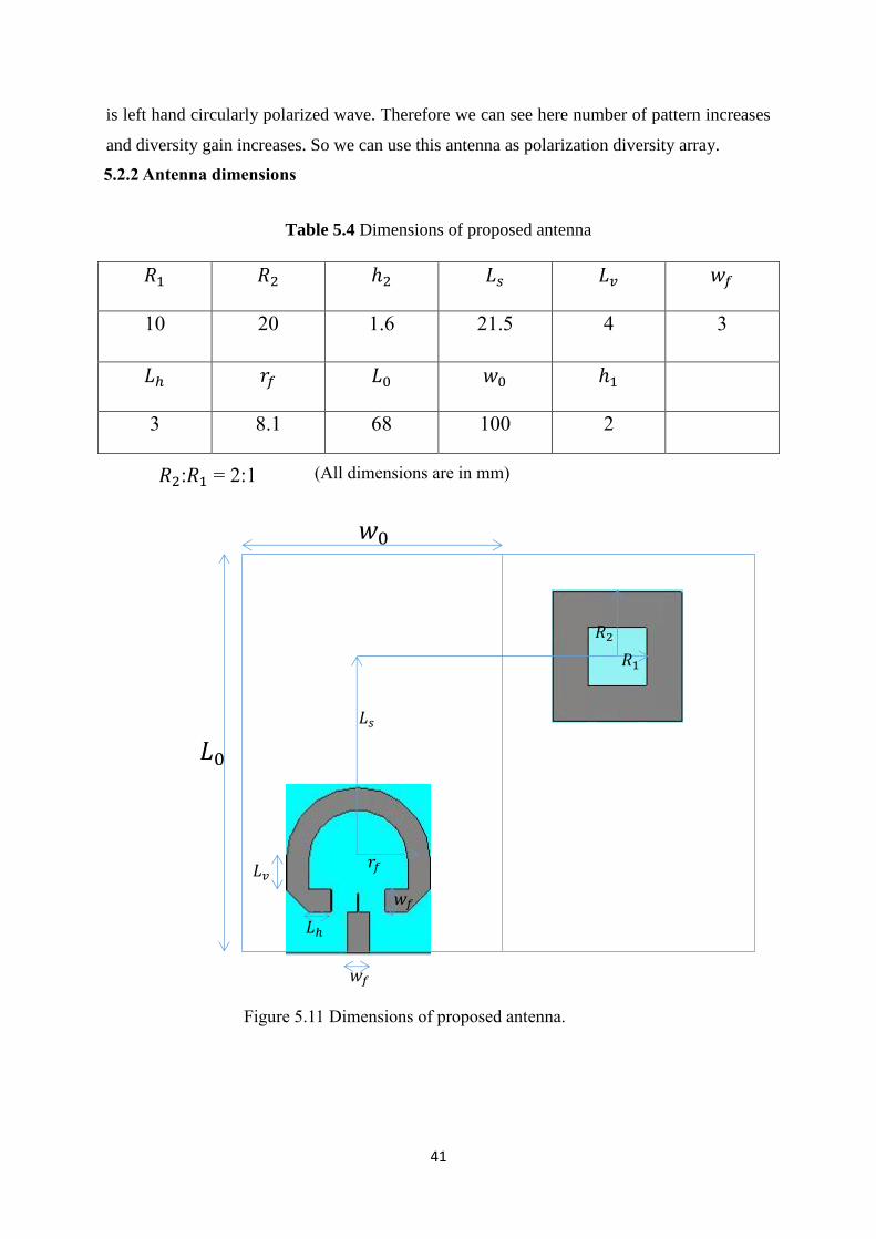
Table 5.4 Dimensions of proposed antenna
𝑅1 𝑅2 ℎ2 𝐿𝑠 𝐿𝑣 𝑤𝑓
10 20 1.6 21.5 4 3
𝐿ℎ 𝑟𝑓 𝐿0 𝑤0 ℎ1
3 8.1 68 100 2
𝐿0
𝑤0
𝑤𝑓
𝐿𝑠
𝑅1
𝑅2
𝑟𝑓 𝐿𝑣
𝐿ℎ
𝑤𝑓
5.2.2 Antenna dimensions
𝑅2:𝑅1 = 2:1 (All dimensions are in mm)
Figure 5.11 Dimensions of proposed antenna.
42
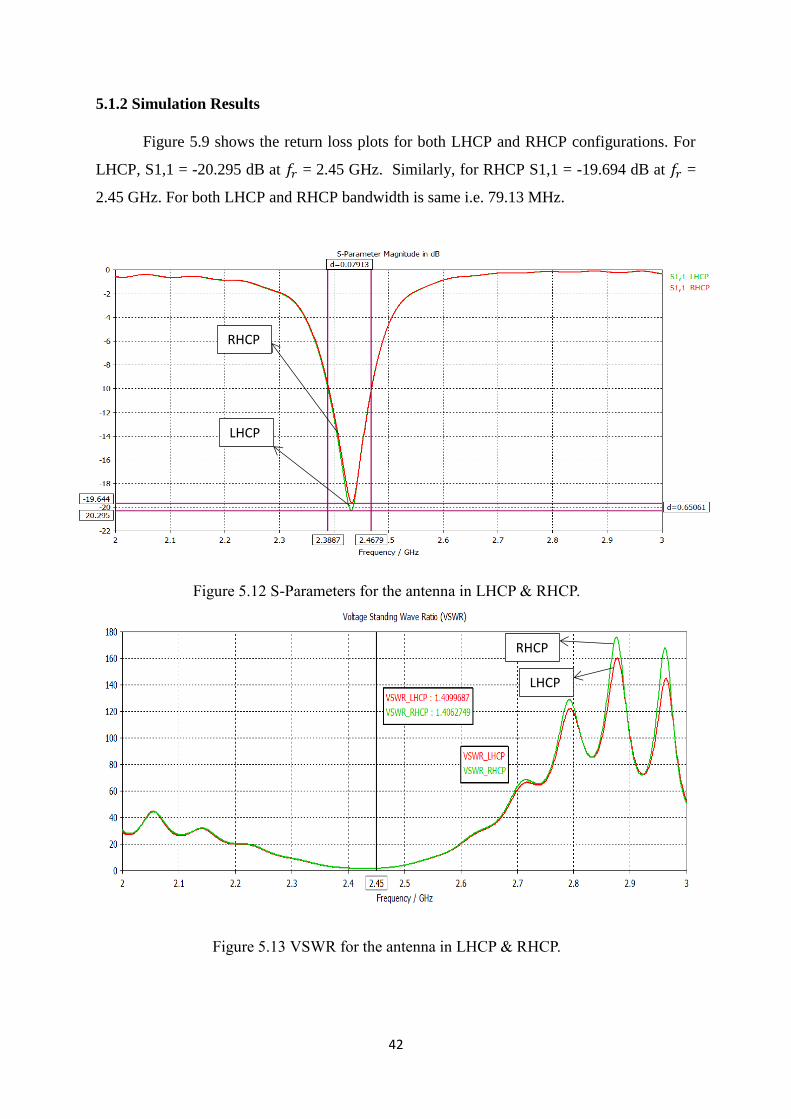
5.1.2 Simulation Results
Figure 5.9 shows the return loss plots for both LHCP and RHCP configurations. For
LHCP, S1,1 = -20.295 dB at 𝑓𝑟 = 2.45 GHz. Similarly, for RHCP S1,1 = -19.694 dB at 𝑓𝑟 =
2.45 GHz. For both LHCP and RHCP bandwidth is same i.e. 79.13 MHz.
Figure 5.12 S-Parameters for the antenna in LHCP & RHCP.
RHCP
LHCP
RHCP
LHCP
Figure 5.13 VSWR for the antenna in LHCP & RHCP.
43
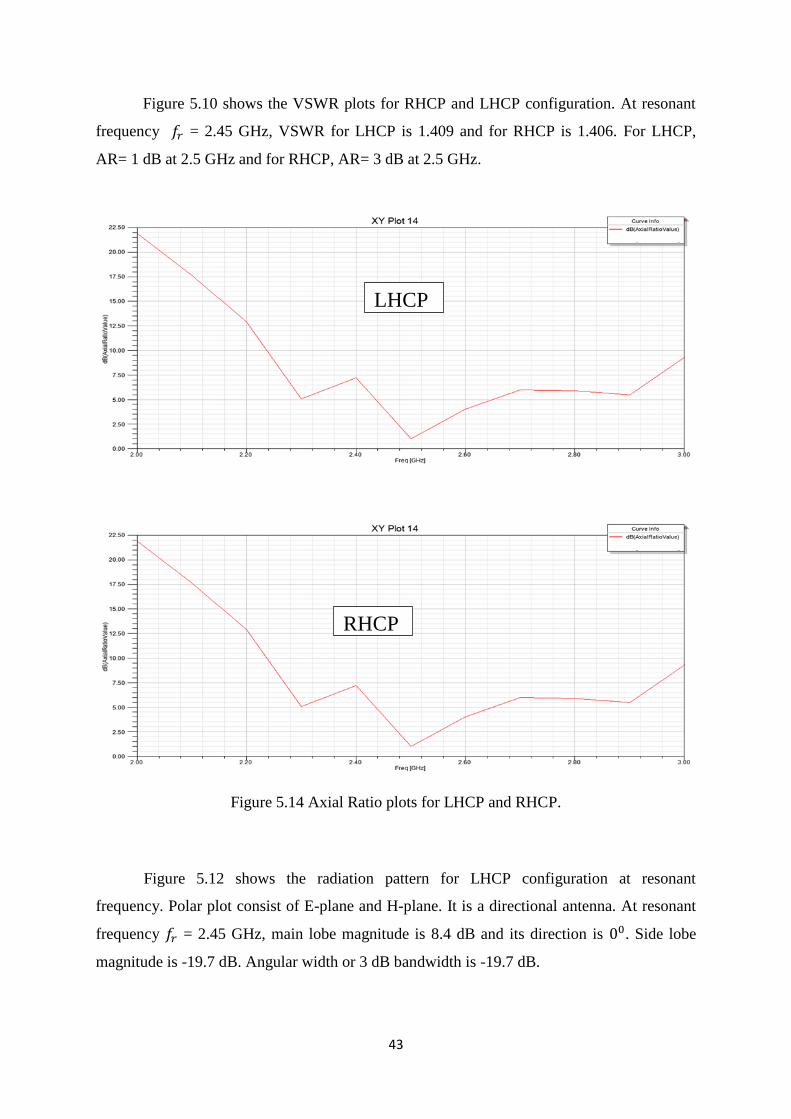
Figure 5.10 shows the VSWR plots for RHCP and LHCP configuration. At resonant
frequency 𝑓𝑟 = 2.45 GHz, VSWR for LHCP is 1.409 and for RHCP is 1.406. For LHCP,
AR= 1 dB at 2.5 GHz and for RHCP, AR= 3 dB at 2.5 GHz.
Figure 5.14 Axial Ratio plots for LHCP and RHCP.
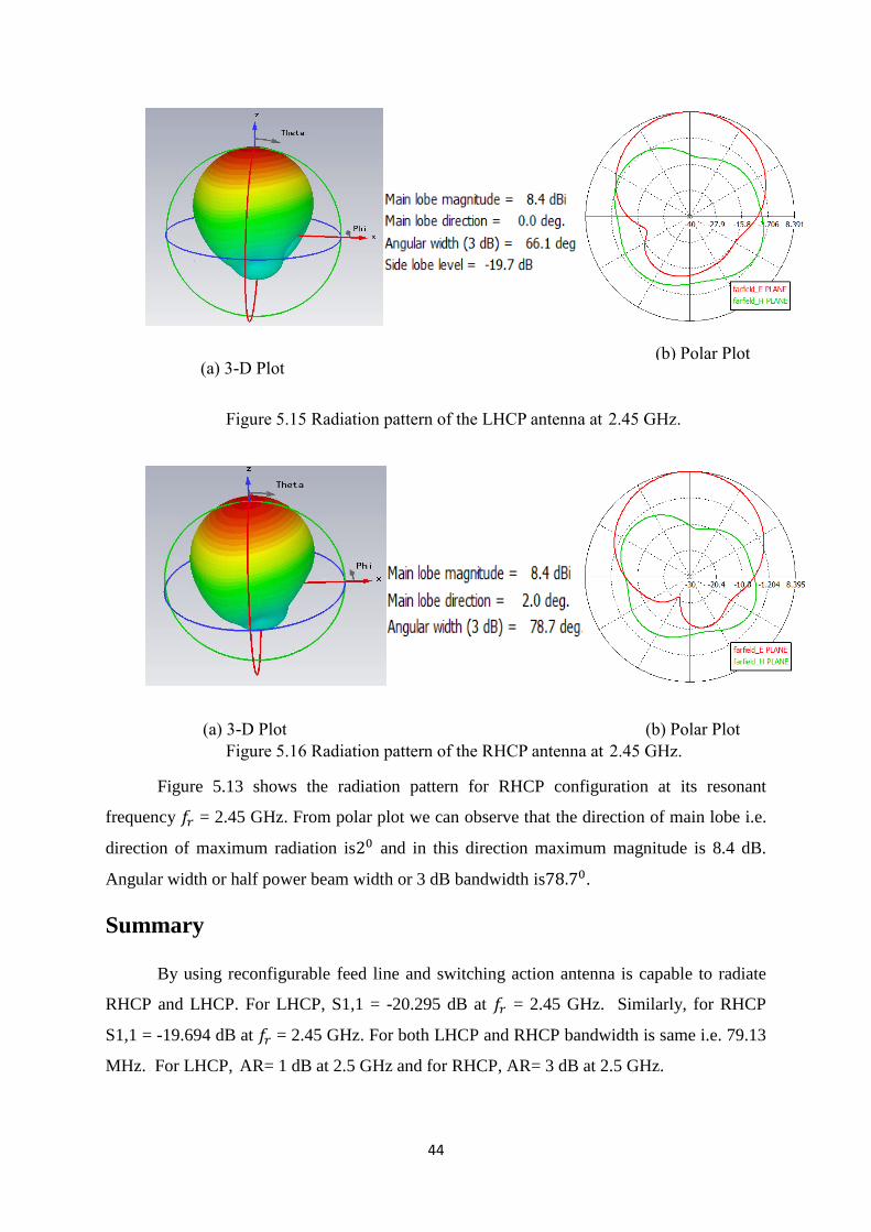
Figure 5.12 shows the radiation pattern for LHCP configuration at resonant
frequency. Polar plot consist of E-plane and H-plane. It is a directional antenna. At resonant
frequency 𝑓𝑟 = 2.45 GHz, main lobe magnitude is 8.4 dB and its direction is 00. Side lobe
magnitude is -19.7 dB. Angular width or 3 dB bandwidth is -19.7 dB.
LHCP
RHCP
44
Figure 5.13 shows the radiation pattern for RHCP configuration at its resonant
frequency 𝑓𝑟 = 2.45 GHz. From polar plot we can observe that the direction of main lobe i.e.
direction of maximum radiation is20 and in this direction maximum magnitude is 8.4 dB.
Angular width or half power beam width or 3 dB bandwidth is78.70.
Summary
By using reconfigurable feed line and switching action antenna is capable to radiate
RHCP and LHCP. For LHCP, S1,1 = -20.295 dB at 𝑓𝑟 = 2.45 GHz. Similarly, for RHCP
S1,1 = -19.694 dB at 𝑓𝑟 = 2.45 GHz. For both LHCP and RHCP bandwidth is same i.e. 79.13
MHz. For LHCP, AR= 1 dB at 2.5 GHz and for RHCP, AR= 3 dB at 2.5 GHz.
(a) 3-D Plot (b) Polar Plot
Figure 5.15 Radiation pattern of the LHCP antenna at 2.45 GHz.
(a) 3-D Plot (b) Polar Plot
Figure 5.16 Radiation pattern of the RHCP antenna at 2.45 GHz.
45
5.3 Design 3
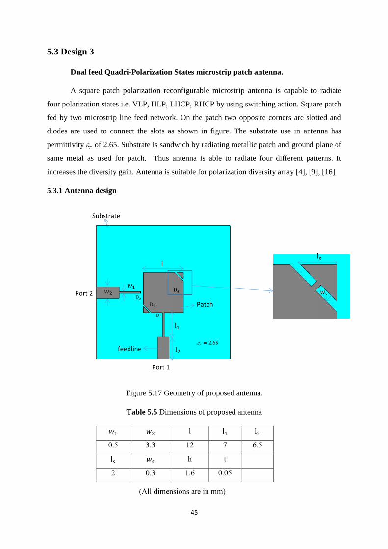
Dual feed Quadri-Polarization States microstrip patch antenna.
A square patch polarization reconfigurable microstrip antenna is capable to radiate
four polarization states i.e. VLP, HLP, LHCP, RHCP by using switching action. Square patch
fed by two microstrip line feed network. On the patch two opposite corners are slotted and
diodes are used to connect the slots as shown in figure. The substrate use in antenna has
permittivity 𝑟 of 2.65. Substrate is sandwich by radiating metallic patch and ground plane of
same metal as used for patch. Thus antenna is able to radiate four different patterns. It
increases the diversity gain. Antenna is suitable for polarization diversity array [4], [9], [16].
5.3.1 Antenna design
Figure 5.17 Geometry of proposed antenna.
Table 5.5 Dimensions of proposed antenna
𝑤1 𝑤2 l l1 l2
0.5 3.3 12 7 6.5
l𝑠 𝑤𝑠 h t
2 0.3 1.6 0.05
l
l1
l2
𝑤2 𝑤1
Port 2
Port 1
D2
D1
D3
D4
Patch
feedline
Substrate
𝑟 = 2.65
l𝑠
𝑤𝑠
(All dimensions are in mm)
46
Table 5.6 Configuration of four pin diodes
D1 D2 D3 D4 Polarization
on off on on LP1(Vertical)
off on on on LP2(Horizontal)
on off off off RHCP
off on off off LHCP
Table 5.5 shows the different configuration with switching action. When diodes D3
and D4 are on then antenna radiates linear polarized wave. In this case when D1 is on and D2
is off then radiated wave is vertical linear polarized wave and when D1 is off and D2 is on
then wave is horizontal linear polarized wave. Similarly, When D3 and D4 are off then
radiated wave is circular polarized wave. In this case when D1 is on and D2 is off then
radiated wave is RHCP and if D1 is off and D2 is on then radiated wave is LHCP wave.
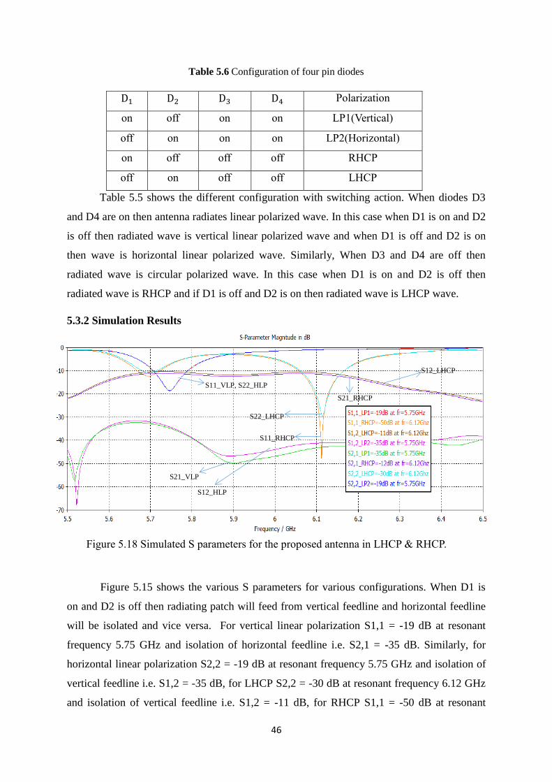
5.3.2 Simulation Results
Figure 5.15 shows the various S parameters for various configurations. When D1 is
on and D2 is off then radiating patch will feed from vertical feedline and horizontal feedline
will be isolated and vice versa. For vertical linear polarization S1,1 = -19 dB at resonant
frequency 5.75 GHz and isolation of horizontal feedline i.e. S2,1 = -35 dB. Similarly, for
horizontal linear polarization S2,2 = -19 dB at resonant frequency 5.75 GHz and isolation of
vertical feedline i.e. S1,2 = -35 dB, for LHCP S2,2 = -30 dB at resonant frequency 6.12 GHz
and isolation of vertical feedline i.e. S1,2 = -11 dB, for RHCP S1,1 = -50 dB at resonant
S11_VLP, S22_HLP
S11_RHCP
S22_LHCP
S21_VLP
S12_HLP
S12_LHCP
S21_RHCP
Figure 5.18 Simulated S parameters for the proposed antenna in LHCP & RHCP.
47
frequency 6.12 GHz and isolation of horizontal feedline i.e. S2,1 = -12 dB. For linear
polarization bandwidth is 0.07 GHz and for circular polarization bandwidth is 0.11 GHz.
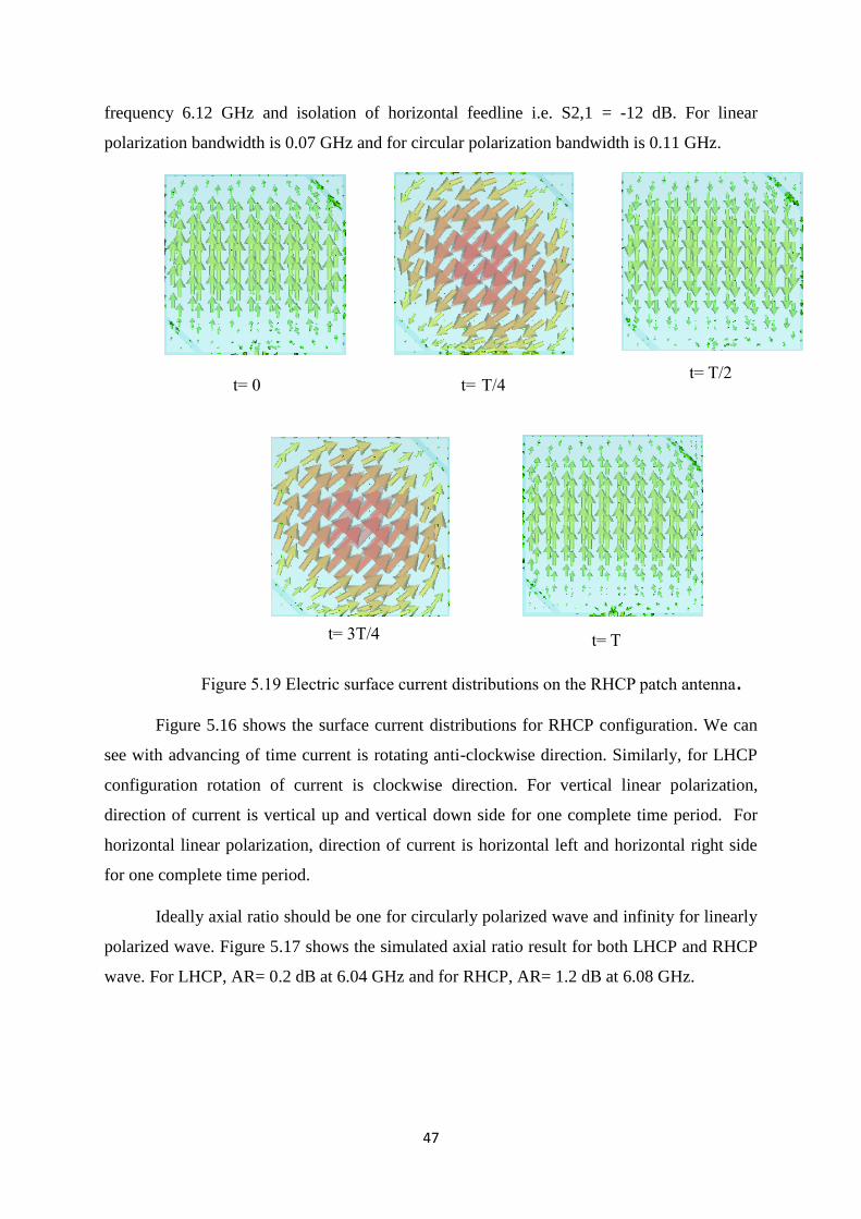
Figure 5.16 shows the surface current distributions for RHCP configuration. We can
see with advancing of time current is rotating anti-clockwise direction. Similarly, for LHCP
configuration rotation of current is clockwise direction. For vertical linear polarization,
direction of current is vertical up and vertical down side for one complete time period. For
horizontal linear polarization, direction of current is horizontal left and horizontal right side
for one complete time period.
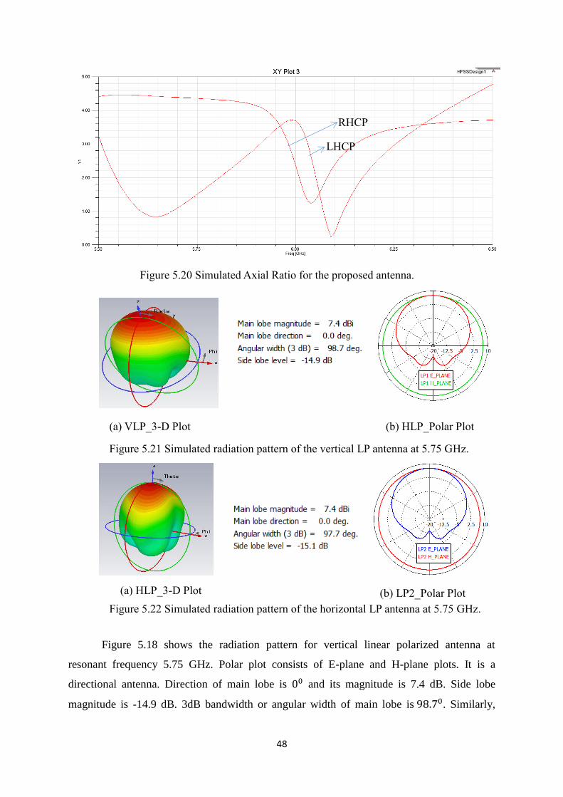
Ideally axial ratio should be one for circularly polarized wave and infinity for linearly
polarized wave. Figure 5.17 shows the simulated axial ratio result for both LHCP and RHCP
wave. For LHCP, AR= 0.2 dB at 6.04 GHz and for RHCP, AR= 1.2 dB at 6.08 GHz.
t= 0 t= T/4 t= T/2
t= 3T/4 t= T
Figure 5.19 Electric surface current distributions on the RHCP patch antenna.
48
Figure 5.18 shows the radiation pattern for vertical linear polarized antenna at
resonant frequency 5.75 GHz. Polar plot consists of E-plane and H-plane plots. It is a
directional antenna. Direction of main lobe is 00 and its magnitude is 7.4 dB. Side lobe
magnitude is -14.9 dB. 3dB bandwidth or angular width of main lobe is 98.70. Similarly,
Figure 5.20 Simulated Axial Ratio for the proposed antenna.
RHCP
LHCP
Figure 5.21 Simulated radiation pattern of the vertical LP antenna at 5.75 GHz.
(a) VLP_3-D Plot (b) HLP_Polar Plot
(a) HLP_3-D Plot (b) LP2_Polar Plot
Figure 5.22 Simulated radiation pattern of the horizontal LP antenna at 5.75 GHz.
49
figure 5.19 shows the radiation pattern for horizontal polarization case. Magnitude of main
lobe is 7.4 dB and its direction is 00. Side lobe magnitude is -15.1 dB. Angular width or 3 dB
bandwidth of main lobe is 97.70.
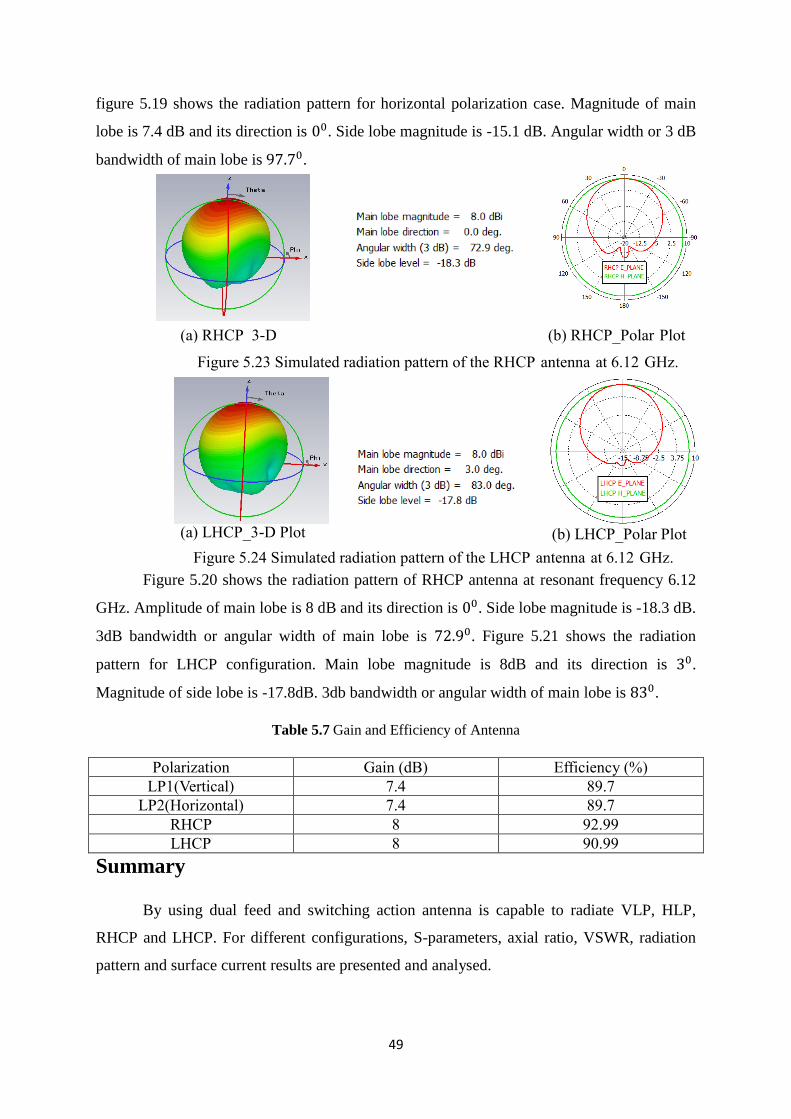
Figure 5.20 shows the radiation pattern of RHCP antenna at resonant frequency 6.12
GHz. Amplitude of main lobe is 8 dB and its direction is 00. Side lobe magnitude is -18.3 dB.
3dB bandwidth or angular width of main lobe is 72.90. Figure 5.21 shows the radiation
pattern for LHCP configuration. Main lobe magnitude is 8dB and its direction is 30.
Magnitude of side lobe is -17.8dB. 3db bandwidth or angular width of main lobe is 830.
Table 5.7 Gain and Efficiency of Antenna
Polarization Gain (dB) Efficiency (%)
LP1(Vertical) 7.4 89.7
LP2(Horizontal) 7.4 89.7
RHCP 8 92.99
LHCP 8 90.99
Summary
By using dual feed and switching action antenna is capable to radiate VLP, HLP,
RHCP and LHCP. For different configurations, S-parameters, axial ratio, VSWR, radiation
pattern and surface current results are presented and analysed.
(a) RHCP_3-D
Plot
(b) RHCP_Polar Plot
Figure 5.23 Simulated radiation pattern of the RHCP antenna at 6.12 GHz.
(a) LHCP_3-D Plot (b) LHCP_Polar Plot
Figure 5.24 Simulated radiation pattern of the LHCP antenna at 6.12 GHz.
50
5.4 Design 4
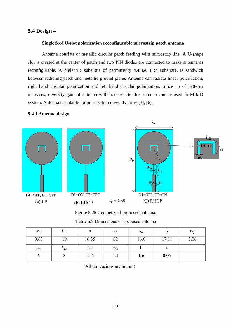
Single feed U-slot polarization reconfigurable microstrip patch antenna
Antenna consists of metallic circular patch feeding with microstrip line. A U-shape
slot is created at the center of patch and two PIN diodes are connected to make antenna as
reconfigurable. A dielectric substrate of permittivity 4.4 i.e. FR4 substrate, is sandwich
between radiating patch and metallic ground plane. Antenna can radiate linear polarization,
right hand circular polarization and left hand circular polarization. Since no of patterns
increases, diversity gain of antenna will increase. So this antenna can be used in MIMO
system. Antenna is suitable for polarization diversity array [3], [6].
5.4.1 Antenna design
Figure 5.25 Geometry of proposed antenna.
Table 5.8 Dimensions of proposed antenna
𝑤𝑚 𝑙𝑚 a 𝑠𝑏 𝑠𝑎 𝑙𝑓 𝑤𝑓
0.63 10 16.35 62 18.6 17.11 3.28
𝑙𝑠1 𝑙𝑠2 𝑙𝑠3 𝑤𝑠 h t
6 8 1.55 1.1 1.6 0.05
(All dimensions are in mm)
D1 D2
a
𝑤𝑚 𝑙𝑚
𝑙𝑓
𝑙𝑠2
𝑙𝑠1
𝑤𝑓
𝑠𝑎
𝑠𝑏 𝑤𝑠
D1=OFF, D2=OFF D1=ON, D2=OFF D1=OFF, D2=ON
(a) LP (b) LHCP (C) RHCP 𝑟 = 2.65
51
D1 D2 Polarization
OFF OFF LP
ON OFF RHCP
OFF ON LHCP
From figure 1.22 we can see the different switching action. When both the diodes are
off then antenna can radiate linearly polarized wave. Similarly, when diode D1 is on and D2
is off then antenna can radiate right hand circular polarized wave and when D1 is off and D2
is on then it can radiate left hand circular polarized wave [10], [12]. Thus we can see by using
switch and U-slot antenna can radiate number of different patterns and increase the diversity
gain to reduce the multi path effects and interference.
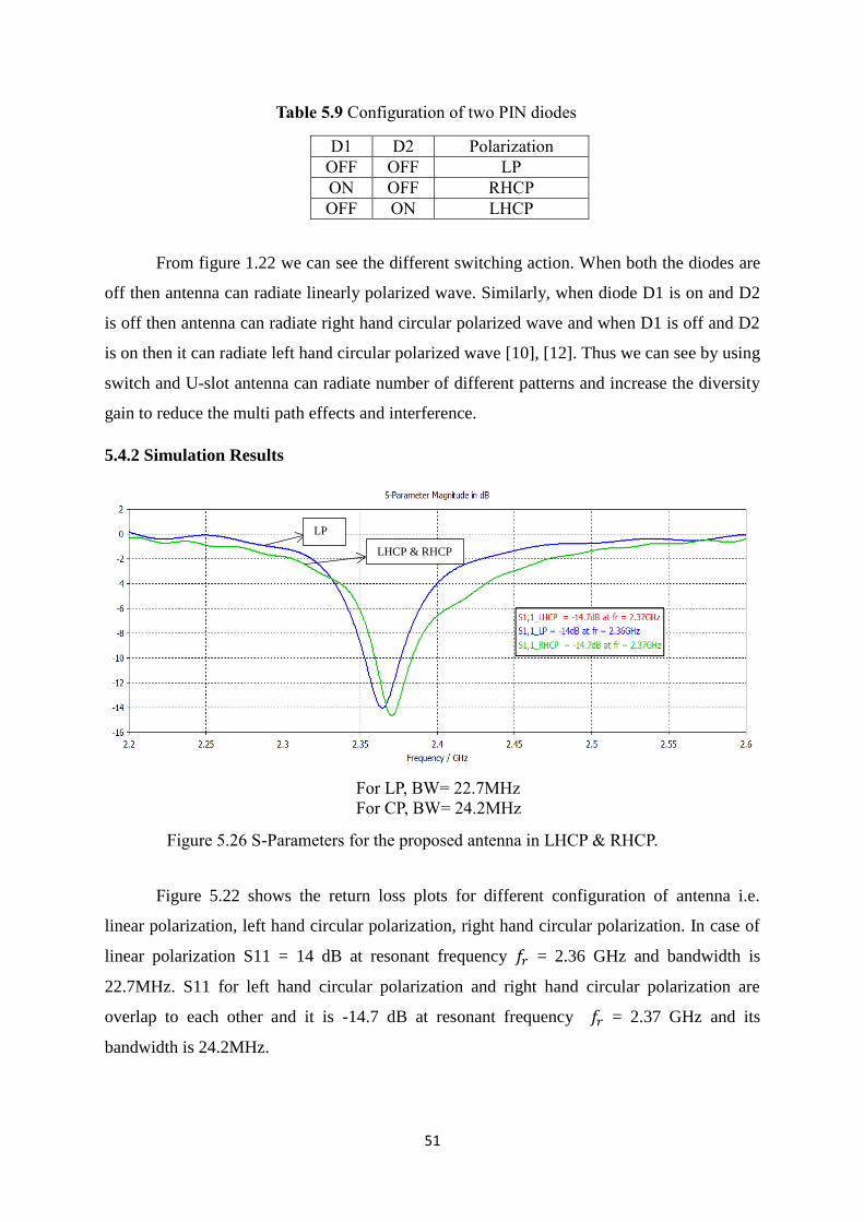
5.4.2 Simulation Results
Figure 5.22 shows the return loss plots for different configuration of antenna i.e.
linear polarization, left hand circular polarization, right hand circular polarization. In case of
linear polarization S11 = 14 dB at resonant frequency 𝑓𝑟 = 2.36 GHz and bandwidth is
22.7MHz. S11 for left hand circular polarization and right hand circular polarization are
overlap to each other and it is -14.7 dB at resonant frequency 𝑓𝑟 = 2.37 GHz and its
bandwidth is 24.2MHz.
Table 5.9 Configuration of two PIN diodes
For LP, BW= 22.7MHz
For CP, BW= 24.2MHz
LP
LHCP & RHCP
Figure 5.26 S-Parameters for the proposed antenna in LHCP & RHCP.
52
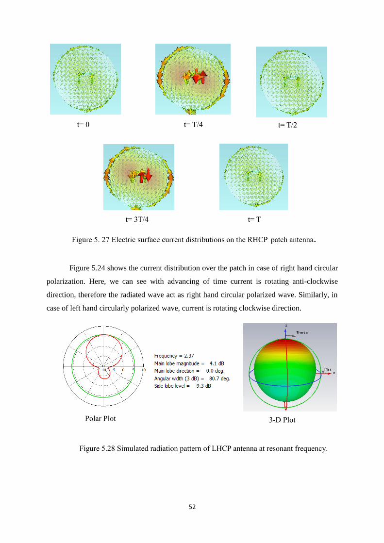
Figure 5.24 shows the current distribution over the patch in case of right hand circular
polarization. Here, we can see with advancing of time current is rotating anti-clockwise
direction, therefore the radiated wave act as right hand circular polarized wave. Similarly, in
case of left hand circularly polarized wave, current is rotating clockwise direction.
t= 0 t= T/4 t= T/2
Figure 5. 27 Electric surface current distributions on the RHCP patch antenna.
t= 3T/4 t= T
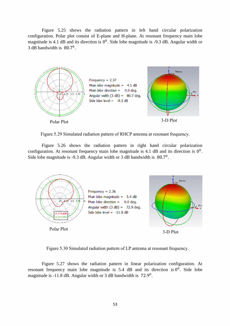
Polar Plot 3-D Plot
Figure 5.28 Simulated radiation pattern of LHCP antenna at resonant frequency.
53
Figure 5.25 shows the radiation pattern in left hand circular polarization
configuration. Polar plot consist of E-plane and H-plane. At resonant frequency main lobe
magnitude is 4.1 dB and its direction is 00. Side lobe magnitude is -9.3 dB. Angular width or
3 dB bandwidth is 80.70.
Figure 5.26 shows the radiation pattern in right hand circular polarization
configuration. At resonant frequency main lobe magnitude is 4.1 dB and its direction is 00.
Side lobe magnitude is -9.3 dB. Angular width or 3 dB bandwidth is 80.70.
Figure 5.27 shows the radiation pattern in linear polarization configuration. At
resonant frequency main lobe magnitude is 5.4 dB and its direction is 00. Side lobe
magnitude is -11.8 dB. Angular width or 3 dB bandwidth is 72.90.
Polar Plot 3-D Plot
Figure 5.29 Simulated radiation pattern of RHCP antenna at resonant frequency.
Polar Plot 3-D Plot
Figure 5.30 Simulated radiation pattern of LP antenna at resonant frequency.
54
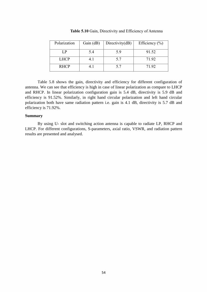
Polarization Gain (dB) Directivity(dB) Efficiency (%)
LP 5.4 5.9 91.52
LHCP 4.1 5.7 71.92
RHCP 4.1 5.7 71.92
Table 5.8 shows the gain, directivity and efficiency for different configuration of
antenna. We can see that efficiency is high in case of linear polarization as compare to LHCP
and RHCP. In linear polarization configuration gain is 5.4 dB, directivity is 5.9 dB and
efficiency is 91.52%. Similarly, in right hand circular polarization and left hand circular
polarization both have same radiation pattern i.e. gain is 4.1 dB, directivity is 5.7 dB and
efficiency is 71.92%.
Summary
By using U- slot and switching action antenna is capable to radiate LP, RHCP and
LHCP. For different configurations, S-parameters, axial ratio, VSWR, and radiation pattern
results are presented and analysed.
Table 5.10 Gain, Directivity and Efficiency of Antenna
55
Chapter 6
Conclusion and Future Work
In this thesis four different polarization reconfigurable antennas with different
geometry are explained. First and second geometry are capable to radiate two
orthogonal pattern i.e. right hand circular polarized and left hand circular polarized
wave. Third design can radiate four different patterns i.e. vertical linear polarized,
horizontal linear polarized, right hand circular polarized and left hand circular
polarized wave. Forth design can radiate three different patterns i.e. linear
polarization, left hand circular polarization and right hand circular polarization. Out of
four, vertical linear polarization and horizontal linear polarization are orthogonal
pattern and right hand circular polarization and left hand circular polarization are
orthogonal pattern. So, by using polarization reconfigurable technique with suitable
bias arrangement and feeding technique we can increase the number of patterns and
increase the diversity gain of antenna. Therefore, we can conclude that Polarization
reconfigurable antennas have the features of multipath effects reduction i.e. reduction
of fading and interference due to increase in diversity gain. So, this design can be
used as a polarization diversity array and suitable for MIMO system.
Since, all the four antennas have very less bandwidth, in future some
optimization technique can be used to increase the bandwidth and enhance the
antenna performance. In future fabrication work for reconfigurable to be done.
56
References
[1] Sennouni, M.A.; Zbitou, J.; Tribak, A.; Benaissa, A.; Latrach, M., "Circular polarized square
patch antenna array for wireless power transmission," Renewable and Sustainable Energy
Conference (IRSEC), 2013 International , vol., no., pp.504,508, 7-9 March 2013.
[2] Jingjing Huang; Kin-Fai Tong; Baker, C., "A new polarization reconfigurable microstrip
antenna for diversity array," Radar Conference, 2008. RADAR '08. IEEE , vol., no., pp.1,4, 26-
30 May 2008.
[3] Taeho Song; Youngki Lee; Deukhyeon Ga; Jaehoon Choi, "A polarization reconfigurable
microstrip patch antenna using PIN diodes," Microwave Conference Proceedings (APMC),
2012 Asia-Pacific , vol., no., pp.616,618, 4-7 Dec. 2012.
[4] Xue-Xia Yang; Bo Gong; Fang Yang; Elsherbeni, A.Z., "A reconfigurable patch antenna with
quadri-polarization states using dual feed ports," Antennas and Propagation Society
International Symposium (APSURSI), 2012 IEEE , vol., no., pp.1,2, 8-14 July 2012.
[5] Parihar, M.S.; Basu, A.; Koul, S.K., "Polarization reconfigurable microstrip
antenna," Microwave Conference, 2009. APMC 2009. Asia Pacific , vol., no., pp.1918,1921, 7-
10Dec.2009.
[6] Sedghara, A.; Atlasbaf, Z., "A new reconfigurable single-feed microstrip antenna with
polarization diversity," Antennas and Propagation (EuCAP), 2013 7th European Conference
on , vol., no., pp.2403,2406, 8-12 April 2013.
[7] Sedghara, A.; Atlasbaf, Z., "Reconfigurable single-feed antenna with switchable
polarization," Electrical Engineering (ICEE), 2013 21st Iranian Conference on , vol., no.,
pp.1,4,14-16May 2013.
[8] Nasimuddin; Esselle, K.P.; Verma, A.K., "Improving the axial-ratio bandwidth of circularly
polarized stacked microstrip antennas and enhancing their gain with short horns," Antennas
and Propagation Society International Symposium 2006, IEEE , vol., no., pp.1545,1548, 9-14
July 2006.
[9] Jeen-Sheen Row; Ming-Jyun Hou, "Design of Polarization Diversity Patch Antenna Based on a
Compact Reconfigurable Feeding Network," Antennas and Propagation, IEEE Transactions
57
on , vol.62, no.10, pp.5349,5352, Oct. 2014.
[10] Noordin, N.H.; Wei Zhou; El-Rayis, A.O.; Haridas, N.; Erdogan, A.T.; Arslan, T., "Single-feed
polarization reconfigurable patch antenna," Antennas and Propagation Society International
Symposium (APSURSI), 2012 IEEE , vol., no., pp.1,2, 8-14 July 2012.
[11] Hettak, K.; Delisle, G.Y.; Morin, G.; Stubbs, M., "A Novel reconfigurable single-feed CPW
coupled patch antenna topology with switchable polarization," Antennas and Propagation
Society International Symposium, 2007 IEEE , vol., no., pp.5199,5202, 9-15 June 2007.
[12] Nikolaou, S.; Boyon Kim; Vryonides, P., "Reconfiguring antenna characteristics using PIN
diodes," Antennas and Propagation, 2009. EuCAP 2009. 3rd European Conference on , vol.,
no., pp.3748,3752, 23-27 March 2009.
[13] Petosa, A.; Ittipiboon, A., "Dielectric Resonator Antennas: A Historical Review and the
Current State of the Art," Antennas and Propagation Magazine, IEEE , vol.52, no.5,
pp.91,116,Oct.2010.
[14] Lo, Y.T., Solomon, D.,and Richards , W.F.,”Theory and Experiment on microstrip Antenna,”
IEEE Transactions on antenna and propagation, March1979, vol. AP-27, pp. 137-149.
[15] Richards, W.F., LO, Y.T., and Harrison, D.D., “An improved theory for microstrip antennas
and application” IEEE Transactions on antenna and propagation January 1981,vol. AP-29,pp.
38-46.
[16] Hansheng Su; Shoaib, I.; Xiadong Chen; Kreouzis, T., "Optically tuned polarisation
reconfigurable antenna," Antennas and Propagation (APCAP), 2012 IEEE Asia-Pacific
Conference on , vol., no., pp.265,266, 27-29 Aug. 2012.
[17] Khidre, A.; Kai-Fong Lee; Fan Yang; Elsherbeni, A.Z., "Circular Polarization Reconfigurable
Wideband E-Shaped Patch Antenna for Wireless Applications," Antennas and Propagation,
IEEE Transactions on , vol.61, no.2, pp.960,964, Feb. 2013.
[18] I-Chian Wu; Shyh-Kang Jeng, "A single-feed switchable wide-band circular polarization E-
shaped patch antenna," Antennas and Propagation Society International Symposium
(APSURSI), 2013 IEEE , vol., no., pp.568,569, 7-13 July 2013.
[19] Hyuck Jin Kim; Ki Suk Yoon; Sung Min Kim; Woon Geun Yang, "Design and
Implementation of Dual-Band Circular Polarization Square Patch Antenna for the Reception of

58
GPS and S-DMB Signals," Antennas and Propagation Society International Symposium 2006,
IEEE , vol., no., pp.2657,2660, 9-14 July 2006.
[20] Randy Bancroft, “Microstrip and Printed Antenna Design” 2nd edition, IET Publication, July
2008.
[21] Constantine A. Balanis “Antenna Theory Analysis and Design” 3rd edition, (WILEY
Publication, 2005).
[22] Antar, Y.M.M., "Microstrip antenna design handbook [Book Review]," Antennas and
Propagation Magazine, IEEE , vol.45, no.2, pp.86,86, April 2003.
[23] Ramesh Garg P.bhatiya, Inder Bahal, A. Ittipiboon “Microstrip Antenna Design Handbook”
(Artech House Publishers, 2001).
[24] K. D. Prasad “Antenna and Wave Propagation” 3rd edition, (Tech India Publications, 2007).
[25] David M. Pozar “Microwave Engineering” 4th
edition, (Wiley Publication, 2013).
[26] Matthew N. O. Sadiku “Elements of Electromagnetics” 4th
edition, ( Published by Oxford
University Press, 2007).