Embed Size (px)
Citation preview

International Journal of Emerging Technologies in Engineering Research (IJETER)
Volume 5, Issue 3, March (2017) www.ijeter.everscience.org
ISSN: 2454-6410 ©EverScience Publications 62
Design and Analysis of Piston in Internal
Combustion Engine Using ANSYS
P.Viswabharathy
Assistant Professor, Department of Mechanical Engineering, Shivani College of Engineering
&Technology,Tiruchirappalli-620 009, India.
N.Jeyakumar
Assistant Professor, Department of Mechanical Engineering, Shivani College of Engineering
&Technology,Tiruchirappalli-620 009, India.
P.kannan
Assistant Professor, Department of Mechanical Engineering, Shivani College of Engineering
&Technology,Tiruchirappalli-620 009, India.
A.Vairamuthu
Research Scholar, Department of Mechanical Engineering, Sethu Institude of Technology,
Virudhunagar - 626 115, India.
Abstract – In this paper, the wok is carried out to measure the
stress and temperature distribution on the top surface of the
piston. In I.C. Engine piston is most complex and important part
therefore for smooth running of vehicle piston should be in proper
working condition. Pistons fail mainly due to mechanical stresses
and thermal stresses. Analysis of piston is done with boundary
conditions, which includes pressure on piston head during
working condition and uneven temperature distribution from
piston head to skirt. The analysis predicts that due to temperature
whether the top surface of the piston may be damaged or broken
during the operating conditions, because damaged or broken
parts are so expensive to replace and generally are not easily
available. The CAD model is created using CREO3.0 TOOL. CAD
model is imported into the Hyper Mesh for geometry cleaning and
meshing purpose. The FEA is performed by using RADIOSS. The
topology optimization of the model is done using OptiStruct
module of Hyper Works software.
Index Terms – I.C Engine, Piston Skirt, Creo 3.0, FEA.
1. INTRODUCTION
Engine pistons are one of the most complex components among
all automotive and other industry field components. The engine
can be called the heart of a vehicle and the piston may be
considered the most important part of an engine [1]. There are
lots of research works proposing, for engine pistons, new
geometries, materials and manufacturing techniques, and this
evolution has undergone with a continuous improvement over
the last decades and required thorough examination of the
smallest details. Notwithstanding all these studies, there are a
huge number of damaged pistons [3]. Damage mechanisms
have different origins and are mainly wearing, temperature, and
fatigue related. The fatigue related piston damages play a
dominant role mainly due to thermal and mechanical fatigue,
either at room or at high temperature. This paper describes the
displacement and stress distribution on piston of internal
combustion engine by using FEA. The FEA is performed by
CAD and CAE software [2]. The main objectives are to
investigate and analyze the thermal stress distribution of piston
at the real engine condition during combustion process. The
paper describes the FEA technique to predict the higher stress
and critical region on the component. The optimization is
carried out to reduce the stress concentration on the piston [4].
Simulate to Innovate Hyper Works. Optimization of piston is
carried out by topology criteria from the result designable and
non-designable area is investigated. Applying different
boundary conditions displacement and stress distribution is
calculated [5]. Software used are CREO3.0 for geometry
creation, Hyper Mesh for meshing, RADIOSS for analysis,
OptiStruct for optimization and Hyper View for post
processing.
1.1 Process Methodology
3D model of piston is imported into the Hyper Mesh for
preprocessing. Preprocessing of model consist of meshing,
selection of material properties, creation of load collectors and
apply boundary conditions on model [7]. Then model is
exported to RADIOSS for solving problem. Results of solution
plotted in Hyper View which is well known postprocessor of
Hyper Works software. For the optimization purpose topology
optimization criteria is selected. According to topology criteria

International Journal of Emerging Technologies in Engineering Research (IJETER)
Volume 5, Issue 3, March (2017) www.ijeter.everscience.org
ISSN: 2454-6410 ©EverScience Publications 63
the designable and non designable space is generated and
subsequently element density contour plot is generate in Hyper
View [6].
Methodology
Drawback of Existing model
Rectifying the drawback
Replace the Material of piston
Analysis of piston
Temperature
Pressure
Total heat flux
2. INTERNAL COMBUSTION ENGINES
An Engine is a device which transforms the chemical energy of
a fuel into thermal energy and uses this thermal energy to
produce mechanical work. Engines normally convert thermal
energy into mechanical work and therefore they are called heat
engines [8].
2.1 Heat engines can be broadly classified:
i) External combustion engines
ii) Internal combustion engines
2.2. External combustion engines:
For example, in steam engine or steam turbine the heat
generated due to combustion of fuel and it is employed to
generate high pressure steam, which is used as working fluid in
a reciprocating engine or turbine. See Figure 1.
2.3 Internal combustion engine:
Internal combustion engines can be classified as Continuous IC
engines and Intermittent IC engines. In continuous IC engines
products of combustion of the fuel enters into the prime mover
as the working fluid. For example: In Open cycle gas turbine
plant. Products of combustion from the combustion chamber
enter through the turbine to generate the power continuously.
See Figure 2. In this case, same working fluid cannot be used
again in the cycle.
In Intermittent internal combustion engine combustion of fuel
takes place inside the engine cylinder. Power is generated
intermittently (only during power stroke) and flywheel is used
to provide uniform output torque. The reciprocating engine
mechanism consists of piston which moves in a cylinder and
forms a movable gas tight seal. By means of a connecting rod
and a crank shaft arrangement, the reciprocating motion of
piston is converted into a rotary motion of the crankshaft [9].
They are most popular because of their use as main prime
mover in commercial vehicles. The shown in figure 3 is layout
of IC engine,
Figure 3: IC Engine
2.4 Advantages of internal combustion engines:
Greater mechanical simplicity.
Higher power output per unit weight because of absence
of auxiliary units like boiler, condenser and feed pump
Low initial cost
Higher brake thermal efficiency as only a small fraction
of heat energy of the fuel is dissipated to cooling system
These units are compact and requires less space

International Journal of Emerging Technologies in Engineering Research (IJETER)
Volume 5, Issue 3, March (2017) www.ijeter.everscience.org
ISSN: 2454-6410 ©EverScience Publications 64
Easy starting from cold conditions
2.5 Disadvantages of internal combustion engines:
I C engines cannot use solid fuels which are cheaper.
Only liquid or gaseous fuel of given specification can be
efficiently used. These fuels are relatively more
expensive.
2. I C engines have reciprocating parts and hence
balancing of them is problem and they are also
susceptible to mechanical vibrations.
3. CLASSIFICATION OF INTERNAL COMBUSTION
ENGINES
There are different types of IC engines that can be classified on
the following basis.
3.1. According to thermodynamic cycle:
i) Otto cycle engine or Constant volume heat supplied cycle.
ii) Diesel cycle engine or Constant pressure heat supplied cycle
iii) Dual-combustion cycle engine
3.2. According to the fuel used:
i) Petrol engine
ii) Diesel engine,
iii) Gas engine
3.3. According to the cycle of operation:
i) Two stroke cycle engine
ii) Four stroke cycle engine
3.4. According to the method of ignition:
i) Spark ignition (S.I) engine
ii) Compression ignition (C I ) engine.
3.5. According to the number of cylinders:
i) Single cylinder engine
ii) Multi cylinder engine
3.6. According to the arrangement of cylinder.
i) Horizontal engine
ii) Vertical engine
iii) V-engine,
v) In-line engine
vi) Radial engine, etc.
3.7. According to the method of cooling the cylinder:
i) Air cooled engine
ii) Water cooled engine
3.8. According to their applications:
i) Stationary engine
ii) Automobile engine,
iii) Aero engine
iv) Locomotive engine,
v) Marine engine, etc.
4. INTERNAL COMBUSTION ENGINE PARTS AND
THEIR FUNCTION
4.1. Cylinder:-
It is a container fitted with piston, where the fuel is burnt and
power is produced [10].
4.2. Cylinder Head/Cylinder Cover:-
One end of the cylinder is closed by means of cylinder head.
This consists of inlet valve for admitting air fuel mixture and
exhaust valve for removing the products of combustion.
4.3. Piston:-
Piston is used to reciprocate inside the cylinder. It transmits the
energy to crankshaft through connecting rod.
4.4. Piston Rings:-
These are used to maintain a pressure tight seal between the
piston and cylinder walls and also it transfer the heat from the
piston head to cylinder walls.
4.5. Connecting Rod:-
One end of the connecting rod is connected to piston through
piston pin while the other is connected to crank through crank
pin. It transmits the reciprocating motion of piston to rotary
crank.
4.6. Crank:
It is a lever between connecting rod and crank shaft.
4.7. Crank Shaft:-
The function of crank shaft is to transform reciprocating motion
in to a rotary motion.
4.8. Fly wheel:-
Fly wheel is a rotating mass used as an energy storing device.
4.9. Crank Case:-
It supports and covers the cylinder and the crank shaft. It is used
to store the lubricating oil.
International Journal of Emerging Technologies in Engineering Research (IJETER)
Volume 5, Issue 3, March (2017) www.ijeter.everscience.org
ISSN: 2454-6410 ©EverScience Publications 65
Figure 4: Crank Case
5. IC ENGINE – TERMINOLOGY
Figure 5: IC Engine – Terminology
5.1 Bore:
The inside diameter of the cylinder is called the bore.
5.2 Stroke:
The linear distance along the cylinder axis between the two
limiting positions of the piston is called stroke.
5.3 Top Dead Centre (T.D.C):
The top most position of the piston towards cover end side of
the cylinder” is called top dead centre. In case of horizontal
engine, it is called as inner dead centre.
5.4 Bottom Dead Centre (B.D.C):
The lowest position of the piston towards the crank end side of
the cylinder is called bottom dead centre. In case of horizontal
engine, it is called outer dead centre (O.D.C).
5.5 Clearance Volume:
The volume contained in the cylinder above the top of the
piston, when the piston is at the top dead centre is called
clearance volume.
5.6 Compression ratio:
It is the ratio of total cylinder volume to clearance volume.
Four-Stroke Petrol Engine OR Four stroke Spark Ignition
Engine (S.I. engine).
6. FOUR STROKE COMPRESSION IGNITION ENGINE
The four stroke cycle diesel engine operates on diesel cycle or
constant pressure cycle [11]. Since ignition in these engines is
due to the temperature of the compressed air, they are also
called compression ignition engines. The construction and
working of the four stroke diesel engine is shown in fig. 4, and
fig. 5 shows a theoretical diesel cycle. The four strokes are as
follows:
Suction
i) Suction stroke
ii) Compression stroke
iii) Working or power or expansion stroke
iv)Exhaust stroke
Figure 6: Four Stroke Diesel Engine
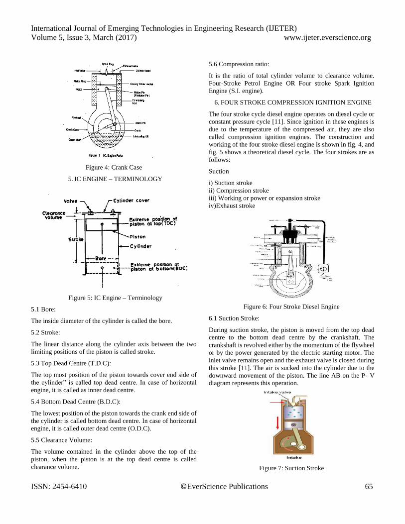
6.1 Suction Stroke:
During suction stroke, the piston is moved from the top dead
centre to the bottom dead centre by the crankshaft. The
crankshaft is revolved either by the momentum of the flywheel
or by the power generated by the electric starting motor. The
inlet valve remains open and the exhaust valve is closed during
this stroke [11]. The air is sucked into the cylinder due to the
downward movement of the piston. The line AB on the P- V
diagram represents this operation.
Figure 7: Suction Stroke

International Journal of Emerging Technologies in Engineering Research (IJETER)
Volume 5, Issue 3, March (2017) www.ijeter.everscience.org
ISSN: 2454-6410 ©EverScience Publications 66
6.2 Compression Stroke:
The air drawn at the atmospheric pressure during suction stroke
is compressed to high pressure and temperature as piston
moves from the bottom dead centre to top dead centre. This
operation is represented by the curve BC on the P- V diagram.
Just before the end of this stroke, a metered quantity of fuel is
injected into the hot compressed air in the form of fine sprays
by means of fuel injector. The fuel starts burning at constant
pressure shown by the line CD. At point D,fuel supply is cut
off, Both the inlet and exhaust valve remain closed during this
stroke [12].
Figure 8: Compression Stroke
6.3 Working Stroke:
The expansion of gases due to the heat of combustion exerts a
pressure on the piston. Under this impulse, the piston moves
from top dead centre to the bottom dead centre and thus work
is obtained in this stroke. Both the inlet and exhaust valves
remain closed during this stroke. The expansion of the gas is
shown by the curve DE [13].
Figure 9: Power stroke
6.4 Exhaust Stroke:
During this stroke, the inlet valve remains closed and the
exhaust valve opens. The greater part of the burnt gases escapes
because of their own expansion. The vertical line EB represents
the drop in pressure at constant volume. The piston moves from
bottom dead centre to top dead centre and pushes the remaining
gases to the atmosphere. When the piston reaches the top dead
centre the exhaust valve closes and the cycle is completed [14].
The line BA on the F- V diagram represents this stroke.
Figure 10: Exhaust stroke
7. FOUR-STROKE PETROL ENGINE (S.I. ENGINE)
The four-stroke cycle petrol engines operate on Otto (constant
volume) cycle shown in Figure 3.0. Since ignition in these
engines is due to a spark, they are also called spark ignition
engines. The four different strokes are:
i) Suction stroke
ii) Compression stroke
iii) Working or power or expansion stroke
iv) Exhaust stroke.
Figure 11: Four-Stroke Petrol Engine
The construction and working of a four-stroke petrol engine is
shown figure 11.
7.1. Suction Stroke:
During suction stroke, the piston is moved from the top dead
centre to the bottom dead centre by the crank shaft. The crank

International Journal of Emerging Technologies in Engineering Research (IJETER)
Volume 5, Issue 3, March (2017) www.ijeter.everscience.org
ISSN: 2454-6410 ©EverScience Publications 67
shaft is revolved either by the momentum of the flywheel or by
the electric starting motor. The inlet valve remains open and
the exhaust valve is closed during this stroke. The
proportionate air-petrol mixture is sucked into the cylinder due
to the downward movement of the piston. This operation is
represented by the line AB on the P-V diagram [15].
Figure 12: Suction Stroke
7.2. Compression Stroke:
During compression stroke, the piston moves from bottom
dead centre to the top dead centre, thus compressing air petrol
mixture. Due to compression, the pressure and temperature are
increased and is shown by the line BC on the P- V diagram.
Just before the end of this stroke the spark - plug initiates a
spark, which ignites the mixture and combustion takes place at
constant volume as shown by the line CD. Both the inlet and
exhaust valves remain closed during this stroke [12].
Figure 13: Compression Stroke
7.3. Working Stroke:
The expansion of hot gases exerts a pressure on the piston. Due
to this pressure, the piston moves from top dead centre to
bottom dead centre and thus the work is obtained in this stroke.
Both the inlet and exhaust valves remain closed during this
stroke. The expansion of the gas is shown by the curve DE.
Figure 14: Power Stroke
7.4. Exhaust Stroke:
During this stroke, the inlet valve remains closed and the
exhaust valve opens. The greater part of the burnt gases escapes
because of their own expansion. The drop in pressure at
constant volume is represented by the line EB. The piston
moves from bottom dead centre to top dead centre and pushes
the remaining gases to the atmosphere. When the piston
reaches the top dead centre the exhaust valve closes and cycle
is completed [14]. This stroke is represented by the line BA on
the P- V diagram. The operations are repeated over and over
again in running the engine. Thus a four stroke engine
completes one working cycle, during this the crank rotate by
two revolutions.
Figure 15: Exhaust Stroke
8. PISTON DESIGN
The piston is designed according to the procedure and
specification which are given in machine design and data hand
books. The dimensions are calculated in terms of SI Units. The
pressure applied on piston head, temperatures of various areas
of the piston, heat flow, stresses, strains, length, diameter of
piston and hole, thicknesses, etc., parameters are taken into
considerations [2,5,7].
8.1. Design Considerations for a Piston:
In designing a piston for an engine, the following points should
be taken into consideration:

International Journal of Emerging Technologies in Engineering Research (IJETER)
Volume 5, Issue 3, March (2017) www.ijeter.everscience.org
ISSN: 2454-6410 ©EverScience Publications 68
It should have enormous strength to withstand the high
pressure.
It should have minimum weight to withstand the inertia
forces.
It should form effective oil sealing in the cylinder.
It should provide sufficient bearing area to prevent
undue wear.
It should have high speed reciprocation without noise.
It should be of sufficient rigid construction to withstand
thermal and mechanical distortions.
It should have sufficient support for the piston pin.
8.2. Procedure for Piston Design parameters:
The procedure for piston designs consists of the
following steps:
Thickness of piston head (tH)
Heat flows through the piston head (H)
Radial thickness of the ring (t1)
Axial thickness of the ring (t2)
Width of the top land (b1)
Width of other ring lands (b2)
8.2.1. Thickness of Piston Head (tH):
The piston thickness of piston head calculated using the
following Grashoff’s formula,
Where
P= maximum pressure in N/mm²
D= cylinder bore/outside diameter of the piston
σt = permissible tensile stress for the material of the piston.
8.2.2. Heat Flow through the Piston Head (H):
The heat flow through the piston head is calculated using the
formula,
𝐇 = 𝟏𝟐. 𝟓𝟔 ∗ 𝐭𝐇 ∗ 𝐊 ∗ 𝐓𝐜 – 𝐓𝐞 (kj/sec)
Where,
K=thermal conductivity of material which is 174.15W/mk
Tc = temperature at centre of piston head in °C.
Te = temperature at edges of piston head in °C.
8.2.3. Radial Thickness of Ring (t1)
Where,
D = cylinder bore in mm
Pw= pressure of fuel on cylinder wall in N/mm². Its value is
limited from 0.025N/mm² to 0.042N/mm². For
Present material, σt is 90Mpa
8.2.4. Axial Thickness of Ring (t2)
The thickness of the rings may be taken as
t2 = 0.7t1 to t1
Let assume t2 =5mm
Minimum axial thickness (t2)
Where nr = number of rings
8.2.5. Width of the top land (b1)
The width of the top land varies from
𝐛𝟏 = 𝐭𝐇 𝐭𝐨 𝟏. 𝟐 ∗ 𝐭𝐇
8.2.6. Width of other lands (b2)
Width of other ring lands varies from
𝐛𝟐 = 𝟎. 𝟕𝟓 ∗ 𝐭𝟐 𝐭𝐨 𝐭𝟐
8.2.7. Maximum Thickness of Barrel (t3)
𝐭𝟑 = 𝟎. 𝟎𝟑 ∗ 𝐃 + 𝐛 + 𝟒. 𝟓𝐦𝐦
Where,
b = Radial depth of piston ring groove
b = t1+0.4
Figure 16: Engineering Details of SS Grade 420

International Journal of Emerging Technologies in Engineering Research (IJETER)
Volume 5, Issue 3, March (2017) www.ijeter.everscience.org
ISSN: 2454-6410 ©EverScience Publications 69
8.3 Creo3.0-Geomentry
Figure 17: Diagram on sketch view
Figure 18: Diagram on sketch view
9. PISTON MODEL -ANSYS 15.0
Figure 19: Modeling on piston skirt
Figure 20: Mesh on hyper in piston skirt
Initial Temperature (450 C)
Temperature setting (12000 C)
Figure 21: Aluminum alloy
Figure 22: Stainless steel

International Journal of Emerging Technologies in Engineering Research (IJETER)
Volume 5, Issue 3, March (2017) www.ijeter.everscience.org
ISSN: 2454-6410 ©EverScience Publications 70
Figure 23: Total Heat Flux Aluminum alloy
Figure 24: Total Heat Flux Stainless steel
10. CONCLUSION
To put it in a nut shell, this paper at continued engineering
research on the IC engine has resulted in performance
improvements through, lean burn combustion fuel injection,
improved combustion area design and weight reduction.
Despite vehicle weight increased. The modified dimensioned
combustion area results in reported to have reduced emission
and fuel economy. The working of piston is analyzed by ansys
workbench. The various properties affecting the piston
performance is justified.
REFERENCES
[1] B.A.Devan1, G. Ravinder “Thermal analysis of aluminum alloy piston”
International Journal of Emerging Trends in Engineering Research
(IJETER), vol. 3 no6,PP: 511 -515 (2015). [2] Ajay Raj Singh, Dr. Pushpendra Kumar Sharma, “Design, Analysis and
Optimization of Three Aluminum Piston Alloys Using FEA” Int. Journal of Engineering Research and Applications, Vol. 4,Issue 1 Version 3,
January 2014,PP.94-102.
[3] Hitesh pandey, Avinchandrakar , PM Bhagwat, “Thermal Stress Analysis of a Speculative IC Engine piston using CAE Tools” int. journal of
Engineering Research and Applications (IJERA), vol.4, issue 11(version-
5),November 2014,PP.60-64. [4] Isam Jasim Jaber and Ajeet Kumar Rai, Design and Analysis of IC
Engine Piston and Piston-Ring Using CATIA and ANSYS Software,
IJMET, Vol.5, 2014.
[5] S.SrikanthReddy,Dr.B.SudheerPremKumar”Thermal Analysis and
Optimization of I.C. Engine Piston Using Finite Element Method” International Journal of Innovative Research in Science Engineering and
Technology.,Vol.2, Issue12, December2013.
[6] A. R.Bhagat1, Y.M. Jibhakate “Thermal Analysis and Optimization of I.C. Engine Piston Using finite Element Method” International Journal of
Modern Engineering Research (IJMER), Vol.2, Issue.4,July-Aug
2012,PP-2919-2921. [7] Aditya Kumar Gupta1, Vinay Kumar Tripathi2, “Design Analysis and
Optimization of Internal Combustion Engine Piston Using CAE tools
ANSYS” IJERA.vol.4, Issue 11(version -5), November 2014. [8] Gudimetal P., Gopinath C.V. “Finite Element Analysis of Reverse
Engineered Internal Combustion Engine Piston”,Asian International
Journal of Science and Technology in Production and Manufacturing Engineering (AIJSTPME), (2009)2(4), PP.85-92.
[9] Yanxia Wang, Yongqi Liu, Haiyan Shi “The Reliability Analysis for
Pistons on Fracture Mechanics”, IEEE 2010,Vol. 4,PP.173-177.
[10] Jadhav Rajendra B, G. J. Vikhe Patil “Computer Aided Design and
Analysis of Piston Mechanism of Four Stroke S.I.Engine” IEEE
2010,Frontiers in automobile and mechanical engineering conference, PP.97-103.
[11] Hideo Okamoto, Nobuo Anno, and Tamotu ltoh “New Computational and Experimental Stress Analysis Method for the Design Decision on
Optimum Piston Configuration of Production Engine” ,Society of
Autonative Engineers (SAE)paper,(1992),PP. 1-5. [12] Yongjun Nie “Finite Element Modeling and Analysis for Key Parts of a
New type Internal Combustion Engine”, International Conferences
onComputer Application and System Modeling, (2010), Vol. 8, PP.181-184.
[13] M. R. Ayatollahi, F. Mohammadi and H. R. Chamani “thermo-
mechanical fatigue life assessment of a diesel engine piston”, Vol. 1, PP. 256-266.
[14] Yan Xia Wang, Hui Gao “Fatigue strength and analysis of diesel engine
piston on finite element analysis”, Advanced Material Research, Vol. 156, (2010), PP. 1086-1089.
[15] D.Janko , Jovanovi,” Finite Element Evaluation and Optimization of
Geometry with DOE”, International Journal for Quality research UDK- 005. Vol.5, No. 1, PP. 39-45, 2011.
![Untere Neckarstraße Piston · PDF file3.8.2 Seizure in the piston pin bore [shrink-fi t connecting rod] .....60 3.8.3 Seizure in the piston pin bore [with piston skirt seizure(s)].....61](https://img.pdfslide.us/doc/110x75/5a71c5597f8b9abb538d1103/untere-neckarstrae-piston-damageswwwboosttowncomenginepistondamagepdfpdf.jpg)

![PISTON TECH - materion.com · material, piston material [or ring groove] and the piston liner and its surface treatment.” 1. A 3D illustration of a piston ring motion 2. With a](https://img.pdfslide.us/doc/110x75/5fcadda8a379fe5ba73c99c0/piston-tech-material-piston-material-or-ring-groove-and-the-piston-liner-and.jpg)