Embed Size (px)
Citation preview
IJRET: International Journal of Research in Engineering and Technology eISSN: 2319-1163 | pISSN: 2321-7308
_______________________________________________________________________________________
Volume: 04 Issue: 06 | June-2015, Available @ http://www.ijret.org 229
DESIGN AND ANALYSIS OF FIXTURE FOR A STONE CRUSHER
BODY
Chetan D. Borse1, Prasad V. Thete
2, Ravi P. Vishwakarma
3, Jainendrakumar S. Yadav
4
1,2,3,4 B. E. Mech.(student), Mechanical Engineering Department, Gokhale Education Society’s R. H. Sapat College of
Engineering, Management Studies & Research, Nasik, Maharashtra, India
Abstract
This paper deals with the design and analysis of the welding fixture for the body of a stone crusher. A fixture is a work-holding or
support device used in the manufacturing industry. Fixtures are used to securely locate (position in a specific location or orientation) and support the work, ensuring that all parts produced using the fixture will maintain conformity and interchange
ability. Locating and supporting areas must usually be large and very sturdy in order to accommodate welding operations; strong
clamps are also a requirement. The toggle clamps are generally used. The body of a stone crusher consists of various plates that
have to be welded to each other with a specified tolerance and weld quality. The material used in the manufacture of different
parts of body of a stone crusher is Mild steel which is one of the most commonly used materials in the field of fabrication. All the
welding processes are carried out by CO2 welding to ensure the quality of weld is as per the requirement. We have modeled a
weld fixture by using UNIGRAPHICS NX8.0 software which is one of the software used for modeling components in most of the
design based industries. While the modeling of the components the material selection is carried out simultaneously based on the
design considerations related to loads, etc. Later the stress concentration and deformation on the baseplate of the weld fixture
have been found by applying certain load on the baseplate, using the Finite Element Analysis (FEA) by using ANSYS software that
provides best output within few seconds. Finally the stress concentration and deformation results are presented in this document.
Key Words: welding fixture, stone crusher body, toggle clamp, modeling, Finite Element Analysis.
--------------------------------------------------------------------***----------------------------------------------------------------------
1. INTRODUCTION
Bucket is the main component of stone crusher. It should be
manufactured as per the accurate dimension. In industry, to
manufacture the component with high accuracy, it must be
properly located and hold against the work table.
1.1 What is Fixture?
A fixture is a device for locating, holding and supporting a
workpiece during a manufacturing operation. This consists of locators, clamps, supports, and fixture body. Fixtures are
essential elements of production processes as they are
required in most of the automated manufacturing,
inspection, and assembly operations. Fixtures must correctly
locate a workpiece in a given orientation with respect to a
welding torch or measuring device, or with respect to
another component. Whenever any component is in space it
will have 6 degrees of freedom and for correct location of
that component it is required to restrict those 6 degrees of
freedom. These degrees of freedom can be restricted by 3-2-
1 location system. Such location must be invariant in the
sense that the devices must clamp and secure the workpiece in that location for the particular processing operation. [1]
Fixture has direct impact upon welding quality, productivity
and cost. Welding fixtures are used for holding different
parts that have to be welded together. Other use of purpose
of fixture is to reduce distortion that is generated during
welding. It helps in reduction of production loss and also
manufacturing lead time for welding, positioning and
holding parts. Variety of residual stresses produced while
welding is responsible for the distortion. There are many
ways to control the residual stresses namely preheating, peening, post weld heat treatment, stress relief by natural
ageing, vibratory stress relief. [2]
1.2 Organization Introduction
SINGH is one of the leading Crushing and Screening
manufacturing conglomerate based in India. Since 1964, the
company is engaged in designing, manufacturing and
supplying World Class Quarry equipment. Right from its
inception, SINGH has been a pioneer.
Reliability and Service are the bywords at SINGH. The
company has a proper ratio of senior & young technocrats.
Along with the invaluable experience of the seniors and the
dynamism as well as eagerness of young team members,
CUSTOMER delight has been an achievable term. In most
parts of the country, a crusher is synonymous with the name
SINGH with more than 15000 installations worldwide.
The Company has been tremendous growth pattern for the
last 4 decades. The Company has thus dedicated all its
resources to delight its customers by providing them with
Quality products and services.
IJRET: International Journal of Research in Engineering and Technology eISSN: 2319-1163 | pISSN: 2321-7308
_______________________________________________________________________________________
Volume: 04 Issue: 06 | June-2015, Available @ http://www.ijret.org 230
1.3 Identification of Problem
Fabrication of body is one of the problems that the
manufacturer is facing during the manufacturing process of
stone crusher because it takes three to four days for
manufacturing.
In manufacturing of jaw stone crusher, fabrication of body is
one of the most important processes. Fabrication of different plates should be very proper of the body, as the success or
failure of the stone crusher is manly depending on the body.
The method they are using for fabrication of the of the body
is conventional which is time consuming and some where
the alignment of the different plates of body is not accurate
due to which there may be a chances of failure of the body
during the working condition of jaw stone crusher.
Actually the need of this project is important for crusher
body because fabrication of different plates of the body
having accurate alignment with heavy load of different
plates is the bigger problem. The handling of different plates
of body is not so easy and the effort require for fabrication is
large as they are using convention method.
One of the problems, which are the sequence they are using
during the fabrication of plates of the crusher body, is time
consuming and large efforts require for handling of plates.
Due to the weight factor the sequencing of different plates
of body during the fabrication is one of the important
parameter due to which more time and effort is require for
handling the plates.
The aim of this project to design a fixture to locate the plates
at correct place, reduce the setting time and analyze the
fixture for the stone crusher body to avoid rejection and the
errors in manufacturing.
2. LITERATURE REVIEW
Various Methods are suggested in the literature for modular
fixture design. Some hybrid techniques were also being used
by researchers. The review is categorized in three major
classes.
2.1 Fixture Design Methods
Jeng and Gill (1997) formulated a fixture design problem in
hierarchical design structure. Mervynet al. (2003) presented
an internet-enabled fixture design system by the use of XML
file format. Rios et al. (2005) and Alarcon et al. (2010)
developed and presented KBE (knowledge based
engineering) application for, modular fixture design. Hunter
et al. (2006) presented a functional design approach in
which the functional requirements and constraints are
considered as an input to the fixture design process. Wang
and Rong (2008) and Sun and Chen (2007) presented the
case based reasoning method to provide a computer aided
fixture design solution. Perremans (1996) developed an
expert system for automatic fixture design [3]
2.2 Fixture Setup and Planning
Toumi et al. (1989) discussed the planning issues and
presented the plans and requirements for automatic setup
and reconfiguration of modular fixtures. Wu et al. (1998) developed the geometric analysis technique with modular
fixture assembly to present the fundamental study of
automated fixture planning. Kang and. Liu and Wang (2007)
presented a hybrid approach in which machining precedence
is determined by knowledge based and feature sequencing is
through geometric reasoning for fixturing setup. [1]
2.3 Fixture Verification and Analysis
Zheng and Qian (2008) presented an efficient algorithm for
optimal fixe locations to enhance localization accuracy and
immobilization capability of 3-D modular fixtures for
complex shapes. Wu et al. (1998) presented a geometric
analysis on fixturing accuracy, clamp planning, fixturing accessibility, and clamping stability for automatic fixture
planning. Song and Rong (2005) presented a methodology
to evaluate the locating scheme and assist fixture designer to
analyze and improve the designed scheme. Kaya (2006)
presented a genetic algorithm (GA) for the optimization of
locating and clamping positions for fixture layout design. [4]
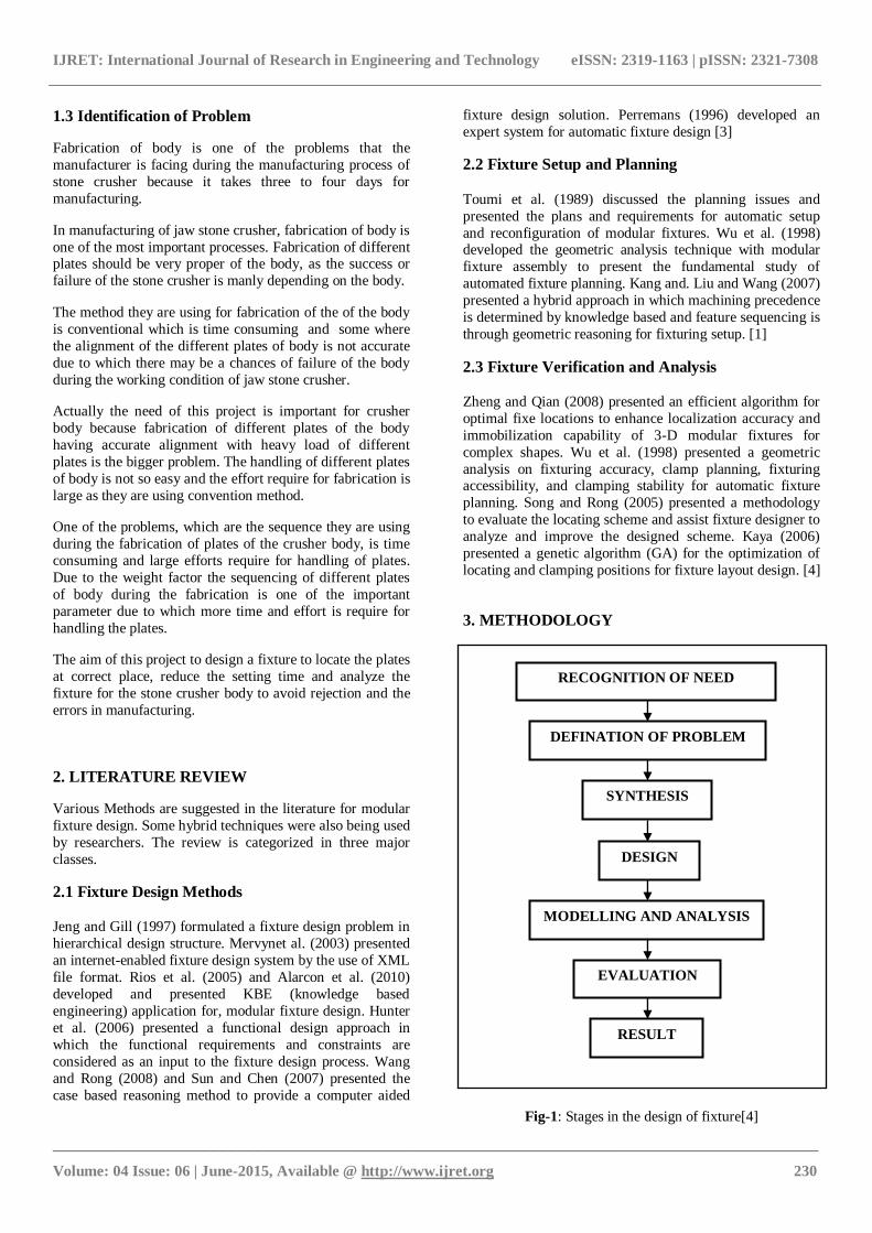
3. METHODOLOGY
Fig-1: Stages in the design of fixture[4]
RECOGNITION OF NEED
DEFINATION OF PROBLEM
SYNTHESIS
DESIGN
MODELLING AND ANALYSIS
EVALUATION
RESULT
IJRET: International Journal of Research in Engineering and Technology eISSN: 2319-1163 | pISSN: 2321-7308
_______________________________________________________________________________________
Volume: 04 Issue: 06 | June-2015, Available @ http://www.ijret.org 231
3.1 Synthesis
Once the problem is defined, the next step is Synthesis. In
this process we are selecting the mechanism, limit, fits,
tolerances, materials, size and shape of the fixture.
3.2 Design
For the designing purpose we select the appropriate yield
strength, ultimate tensile strength of Mild Steel, also we find
out different parameter of fixture and clamping force which
is required for the fixture.
3.4 Evaluation
To check the stresses induced in the fixture are less or
greater than allowable stresses.
3.5 Result
By using ANSYS WORKBENCH we predict the result.
That is stress in induced in the fixture and stress induced in the actual working on the machine.
4. DESIGN AND ANALYSIS OF FIXTURE
4.1 Material Selection
The material selected for fixture is MILD STEEL. [4] Steel
is any alloy of iron, consisting of 0.2% to 2.1% of carbon, as
a hardening agent. What is known as mildest grade of carbon steel or mild steel is typically the variety which has a
comparatively low amount of carbon (0.05% - 0.26%).
The properties of mild steel
The density of mild steel is 7861.093 kg/m3.
Young's modulus, a measure of its stiffness is
around 210,000 MPa.
Compared to other types of steel, this type is ideal
for welding purposes, as it conducts electric current
effectively without tarnishing the metal surface in
any way.
Mild steel can be machined and shaped easily due
to its inherent flexibility.
4.2 Welding Fixture
This fixture is use to locate the various plates on their respective positions on Base plate, with the help of which
following operations will going to perform on component
sequentially:
Perfect positioning
Proper aligning
Proper supporting
Welding
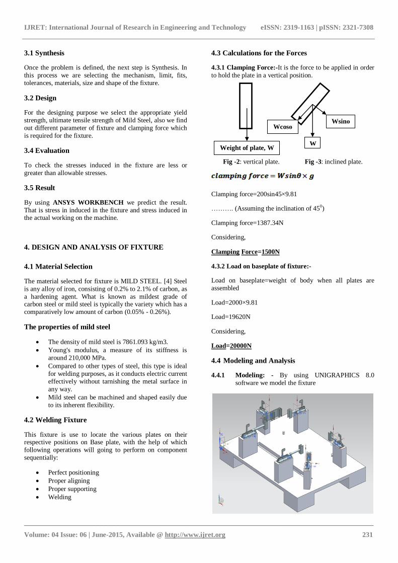
4.3 Calculations for the Forces
4.3.1 Clamping Force:-It is the force to be applied in order
to hold the plate in a vertical position.
Fig -2: vertical plate. Fig -3: inclined plate.
Clamping force=200sin45×9.81
………. (Assuming the inclination of 450)
Clamping force=1387.34N
Considering,
Clamping Force=1500N
4.3.2 Load on baseplate of fixture:-
Load on baseplate=weight of body when all plates are
assembled
Load=2000×9.81
Load=19620N
Considering,
Load=20000N
4.4 Modeling and Analysis
4.4.1 Modeling: - By using UNIGRAPHICS 8.0
software we model the fixture
Weight of plate, W
Wsinɵ Wcosɵ
W
IJRET: International Journal of Research in Engineering and Technology eISSN: 2319-1163 | pISSN: 2321-7308
_______________________________________________________________________________________
Volume: 04 Issue: 06 | June-2015, Available @ http://www.ijret.org 232
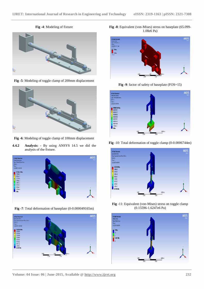
Fig -4: Modeling of fixture
Fig -5: Modeling of toggle clamp of 200mm displacement
Fig -6: Modeling of toggle clamp of 100mm displacement
4.4.2 Analysis: - By using ANSYS 14.5 we did the
analysis of the fixture.
Fig -7: Total deformation of baseplate (0-0.000049165m)
Fig -8: Equivalent (von-Mises) stress on baseplate (65.099-
1.08e6 Pa)
Fig -9: factor of safety of baseplate (FOS=15)
Fig -10: Total deformation of toggle clamp (0-0.0006744m)
Fig -11: Equivalent (von-Mises) stress on toggle clamp
(0.15596-1.6247e6 Pa)
IJRET: International Journal of Research in Engineering and Technology eISSN: 2319-1163 | pISSN: 2321-7308
_______________________________________________________________________________________
Volume: 04 Issue: 06 | June-2015, Available @ http://www.ijret.org 233
Fig -12: Factor of safety of toggle clamp (FOS=1.5-15)
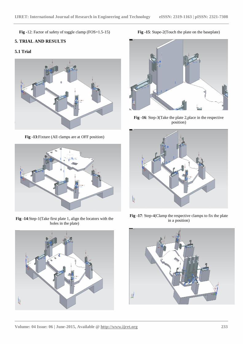
5. TRIAL AND RESULTS
5.1 Trial
Fig -13:Fixture (All clamps are at OFF position)
Fig -14:Step-1(Take first plate 1, align the locators with the
holes in the plate)
Fig -15: Stape-2(Touch the plate on the baseplate)
Fig -16: Step-3(Take the plate 2,place in the respective
position)
Fig -17: Step-4(Clamp the respective clamps to fix the plate
in a position)
IJRET: International Journal of Research in Engineering and Technology eISSN: 2319-1163 | pISSN: 2321-7308
_______________________________________________________________________________________
Volume: 04 Issue: 06 | June-2015, Available @ http://www.ijret.org 234
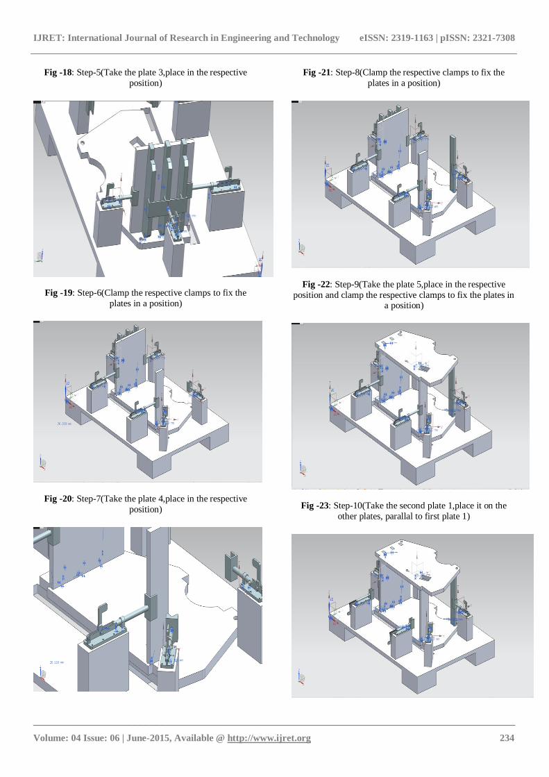
Fig -18: Step-5(Take the plate 3,place in the respective
position)
Fig -19: Step-6(Clamp the respective clamps to fix the
plates in a position)
Fig -20: Step-7(Take the plate 4,place in the respective
position)
Fig -21: Step-8(Clamp the respective clamps to fix the
plates in a position)
Fig -22: Step-9(Take the plate 5,place in the respective
position and clamp the respective clamps to fix the plates in a position)
Fig -23: Step-10(Take the second plate 1,place it on the
other plates, parallal to first plate 1)
IJRET: International Journal of Research in Engineering and Technology eISSN: 2319-1163 | pISSN: 2321-7308
_______________________________________________________________________________________
Volume: 04 Issue: 06 | June-2015, Available @ http://www.ijret.org 235
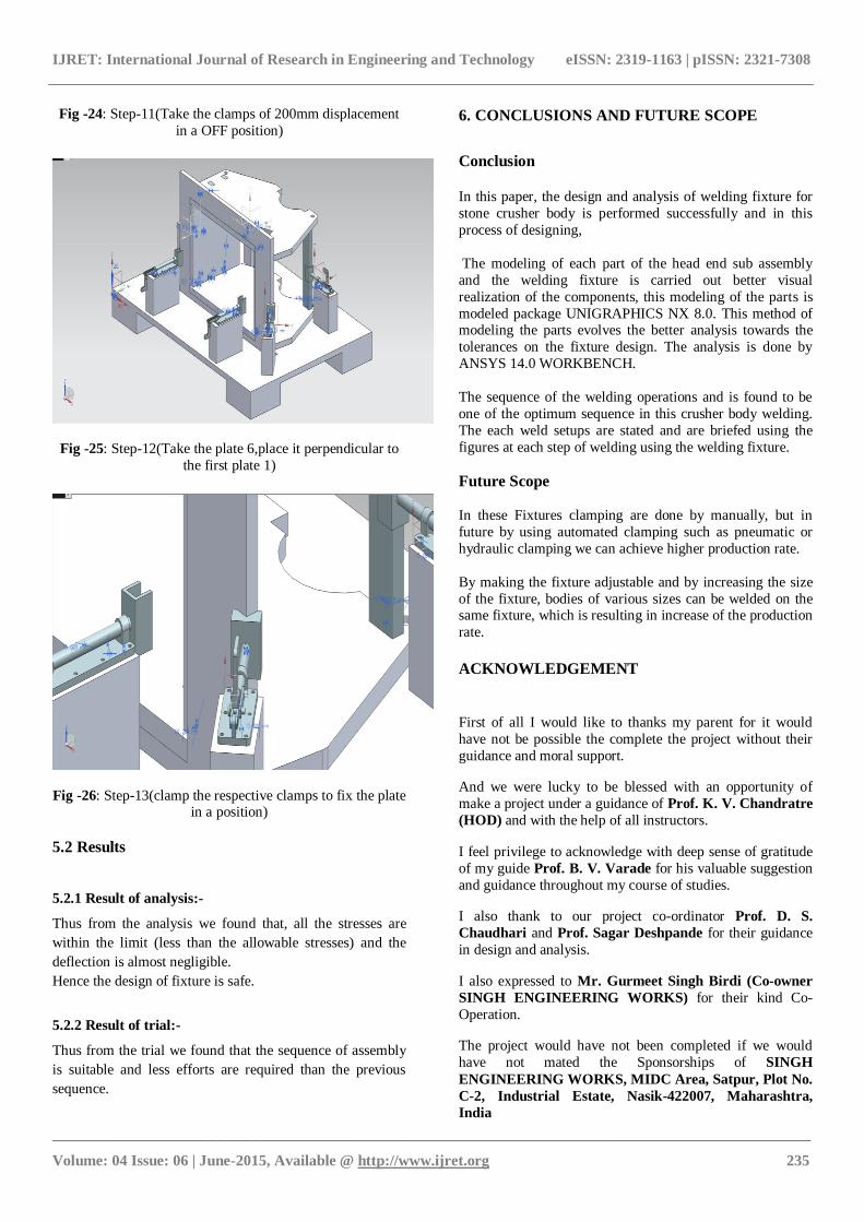
Fig -24: Step-11(Take the clamps of 200mm displacement
in a OFF position)
Fig -25: Step-12(Take the plate 6,place it perpendicular to
the first plate 1)
Fig -26: Step-13(clamp the respective clamps to fix the plate in a position)
5.2 Results
5.2.1 Result of analysis:-
Thus from the analysis we found that, all the stresses are
within the limit (less than the allowable stresses) and the
deflection is almost negligible.
Hence the design of fixture is safe.
5.2.2 Result of trial:-
Thus from the trial we found that the sequence of assembly
is suitable and less efforts are required than the previous
sequence.
6. CONCLUSIONS AND FUTURE SCOPE
Conclusion
In this paper, the design and analysis of welding fixture for
stone crusher body is performed successfully and in this
process of designing,
The modeling of each part of the head end sub assembly
and the welding fixture is carried out better visual
realization of the components, this modeling of the parts is
modeled package UNIGRAPHICS NX 8.0. This method of modeling the parts evolves the better analysis towards the
tolerances on the fixture design. The analysis is done by
ANSYS 14.0 WORKBENCH.
The sequence of the welding operations and is found to be
one of the optimum sequence in this crusher body welding.
The each weld setups are stated and are briefed using the
figures at each step of welding using the welding fixture.
Future Scope
In these Fixtures clamping are done by manually, but in
future by using automated clamping such as pneumatic or
hydraulic clamping we can achieve higher production rate.
By making the fixture adjustable and by increasing the size
of the fixture, bodies of various sizes can be welded on the same fixture, which is resulting in increase of the production
rate.
ACKNOWLEDGEMENT
First of all I would like to thanks my parent for it would
have not be possible the complete the project without their
guidance and moral support.
And we were lucky to be blessed with an opportunity of
make a project under a guidance of Prof. K. V. Chandratre
(HOD) and with the help of all instructors.
I feel privilege to acknowledge with deep sense of gratitude
of my guide Prof. B. V. Varade for his valuable suggestion
and guidance throughout my course of studies.
I also thank to our project co-ordinator Prof. D. S.
Chaudhari and Prof. Sagar Deshpande for their guidance
in design and analysis.
I also expressed to Mr. Gurmeet Singh Birdi (Co-owner
SINGH ENGINEERING WORKS) for their kind Co-
Operation.
The project would have not been completed if we would
have not mated the Sponsorships of SINGH
ENGINEERING WORKS, MIDC Area, Satpur, Plot No.
C-2, Industrial Estate, Nasik-422007, Maharashtra,
India
IJRET: International Journal of Research in Engineering and Technology eISSN: 2319-1163 | pISSN: 2321-7308
_______________________________________________________________________________________
Volume: 04 Issue: 06 | June-2015, Available @ http://www.ijret.org 236
REFERENCES
[1] “JIGS AND FIXTURE DESIGN”, Edward G. Hoffman;
Thomson Publications; Fifth Edition.
[2]. Hui Wang, Yiming (Kevin) Rong,” Case based
reasoning method for computer aided welding xture design”,
Polytechnic Institute, Worcester: May,2005.
[3]. Rong, Y and Zhu, Y, 1999; “Computer-Aided Fixture
Design”, Marcel Dekker Inc. NY; 1999.
[4]. H. Song and Y. Rong; Locating completeness
evaluation and revision in fixture plan, Robotics and Computer-Integrated Manufacturing 21 (2005) 368–378
BIOGRAPHIES
Pursuing Final Year in Bachelor of
Mechanical Engineering degree
from GES’s R.H.S.C.O.E, Nasik,
under the affiliation of University
of Pune, Maharashtra, India.
Pursuing Final Year in Bachelor of
Mechanical Engineering degree
from GES’s R.H.S.C.O.E, Nasik,
under the affiliation of University
of Pune, Maharashtra, India.
Pursuing Final Year in Bachelor of
Mechanical Engineering degree
from GES’s R.H.S.C.O.E, Nasik,
under the affiliation of University
of Pune, Maharashtra, India.
Pursuing Final Year in Bachelor of
Mechanical Engineering degree
from GES’s R.H.S.C.O.E, Nasik,
under the affiliation of University
of Pune, Maharashtra, India.