Embed Size (px)
Citation preview
1
Design and analysis of aerostatic spindle with high load
characteristics for large ultra-precision drum lathe
Dongxu Wu1, Bo Wang1,*, Xichun Luo2, Zheng Qiao1
1. Center for Precision Engineering, Harbin Institute of Technology, Harbin, 15001, P. R. China
2. Centre for Precision Manufacturing, Department of Design, Manufacture and Engineering Management,
Faculty of Engineering, University of Strathclyde, Glasgow G1 1XJ, UK.
Bo Wang, Center for Precision Engineering, Harbin Institute of Technology, 92 West Dazhi Street, Nan Gang
District, Harbin, 15001, P. R. China. Email: [email protected], telephone number: +86-0451-86415244
Abstract
Aerostatic spindles offer low heat generation and high rotation accuracy which make them an
ideal choice for ultra-precision drum lathe where extremely high motional accuracy and
thermal stability are required. However, the limitations such as insufficient load capacity and
stiffness have restricted their permissible application range and make them not suitable for
large ultra-precision machine tools including drum lathe. In order to improve the load
capacity and stiffness, this paper presents a high load capacity aerostatic spindle with
pocketed orifice-type restrictors. Fluent is adopted and three-dimensional simulation models
of aerostatic spindle with orifice and feeding pocket are set up to analyse the load
characteristics. The simulation results show that this restrictor can enhance the throttling
effect of orifice and suppress the pressure drop away from the orifice. Moreover, for
aerostatic journal bearing, when eccentricity ratio is in the range of 0.2-0.3 and gas supply
pressure is 0.6 MPa, carrying capacity and stiffness can reach up to 9499.4 N and 2813.1
N/μm. Finally, a group of loading experiments are carried out which prove that the novel
three-dimensional simulation method is feasible and accurate to calculate the load
characteristics of aerostatic spindles.
Keywords
Ultra-precision, aerostatic spindle, orifice-type restrictor, carrying capacity, stiffness
2
1. Introduction
Ultra-precision machine tools have various applications in manufacturing some
components with optical quality surfaces, microstructured surfaces or free-form surfaces [1-
3]. Ultra-precision drum lathes play an important role in machining large-scale
microstructured drum molds [4-6] which are widely used in roll-to-roll process for mass
production of TFT panel films and antireflective polymer optical film etc. [7, 8]. These
machine tools are required to possess high structural stiffness, load capacity and position
accuracy, as well as good damping property and thermal stability in order to maintain long
term machining accuracy. For example, microstructures of 20 μm must be generated on the
drum molds over a length of 2000 mm with form accuracy of 5 μm, and the pitch variation
should be less than ±0.2 µm for one particular application [9]. Currently, due to high
productivity and cost reduction in manufacturing microstructured surfaces, the drum molds
than 2000 mm long are increasingly required in the market. The weight of such drum molds
can even reach 1000 kg which proposes extremely high requirements in carrying capacity and
stiffness for the machine tool spindles. As a result, oil hydrostatic spindles are normally
adopted in large ultra-precision drum lathes to achieve high carrying capacity up to 3000 kg
and stiffness more than 850 N/μm [10]. However, thermal deformation of oil hydrostatic
bearing will cause excessive pitch error on the machined microstructures and degrade
machining accuracy [11]. Compared with oil hydrostatic bearings, aerostatic bearings have
the advantages of small friction, low heat generation and high rotation accuracy, etc.
Aerostatic bearing is named as externally pressurized gas bearing. When it is working at a
low rotating speed, macroscopic property behaved by the aerostatic effect of the high
pressurized gas will play a dominant role in load characteristics [12]. Even if aerostatic
bearings have been widely used in ultra-precision machine tools and precision instruments for
aviation and aerospace industries, some limitations such as insufficient load capacity and
3
stiffness have restricted their permissible application, especially in large ultra-precision drum
lathe. This is because excessive gas supply pressure will result in a supersonic zone, which
can lead to a sudden drop in carrying capacity. In addition, during the design of aerostatic
bearing, choosing incompatible bearing parameters, such as diameter of orifice and gas film
thickness, will cause self-excited vibration. In this case, bearing cannot work normally,
especially for high pressure and heavy load gas bearings [13, 14]. Moreover, the pneumatic
or whirl instability is likely to occur if aerostatic journal bearing is working at very low or
high speed [15]. Therefore, how to improve the load capacity and stiffness is very important
to the promotion and application of aerostatic bearings.
Yoshimoto [16] used the elastic deformation of O-ring to achieve higher static stiffness
and greater load capacity. Compared with rigid support, the O-ring could present a lower
viscous resistance below the rotor and a larger pressure reduction rate above the rotor in the
axial direction. However, the structure and installation were more complicated than
conventional point source bearings. Additionally, several previous investigations proved that
porous resistance inserted in feeding system could improve the load characteristics, but gas
flow characteristics of porous material had not been fully understood, and
the design and fabrication of the porous material also added more complexity [17-19]. The
research result of Du et al. [20], who studied the relationship between pressure-equalizing
groove and load characteristics of aerostatic journal bearings, showed that pressure-
equalizing groove both in circumferential and axial directions could improve the load
capacity and stiffness. Long et al. [21] carried out some research on the entrance effect of
aerostatic thrust bearing, and the research results showed that for orifice compensated
aerostatic bearing, feeding pocket can improve load capacity with the same geometric
parameters. However, appropriate bearing parameters have to be chosen correctly. Even
though a great deal of excellent research works has been carried out in order to improve
4
carrying capacity and stiffness of the aerostatic bearing, it remains a big challenge in the
design of large scale and heavy load aerostatic bearing, especially for aerostatic journal
bearing. As mentioned above, oil hydrostatic spindles are normally adopted on large ultra-
precision drum lathe due to the high load capacity and stiffness. However, the cooling
devices must be installed in the oil hydrostatic spindles to decrease the thermal deformation.
Development of new design and analysis approach for high carrying capacity and stiffness
aerostatic bearings therefore, becomes an important task for large ultra-precision drum lathe.
For this aim, the flow characteristics of lubricating gas in restrictor should be analyzed
in order to fully understand the load characteristics of aerostatic bearing. Fourka et al. [22]
presented a non-linear model for the stability analysis of air thrust bearing. The model was
based on the finite element method, and the calculated stability threshold by the non-linear
model was more precise compared with the linear analysis. The experimental study
conducted by Belforte et al. [23] showed that for different types of orifice, such as annular
orifice and simple orifice with feeding pocket, the flow characteristics could be described by
using different discharge coefficients. Neves et al. [24] believed that the value of the orifice
discharge coefficient was variable as a function of the pressure ratio, orifice throat discharge
and supply pressures since feeding orifices could operate at either sonic or subsonic flow
conditions. Yang et al. [15] studied the stability threshold and critical whirl ratio of a rigid
rotor-aerostatic bearing system using the perturbation method and eigen-solution method.
Dong et al. [25] adopted differential quadrature method to discretize the Reynolds equation as
a series of algebraic equations, which could be used to analyze the load performance of
aerostatic thrust bearings.
The manufacturing errors have a significant effect on the air flow and bearing
performance of aerostatic bearings. Pande and Somasundaram [26] reported that the
deviations in bearing surfaces from the ideal geometry significantly affected the performance
5
characteristics of aerostatic journal bearings. As a result, form errors reduced the load
capacity by 10-12%, and surface roughness decreased the load capacity by 15-20% and
decreased the flow rate by 10-12% compared with a smooth bearing. Khalil and El-Shorbagy
[27] pointed out that surface roughness reduced the lubricant flow rate and increased the
frictional power. Kwan and Post [28] believed that both static load and stiffness are sensitive
to the manufacturing error such as surface form errors and changes in orifice diameter.
As the computational fluid dynamics (CFD) software is emerging, the analytical
approach of aerostatic bearings' performance has become more diverse. Renn et al. [29]
proposed a new model of the mass flow rate characteristic through an orifice in the aerostatic
bearing through experimental and CFD simulation study. Compared with the conventional
model, the value of the critical pressure ratio was the major difference. Li et al. [30]
conducted a simulation and experimental research which showed that aerostatic thrust
bearing would have good performance if orifice diameter and film thickness were small,
while air chamber diameter was big. Although many efforts have been made to study the load
performance of aerostatic bearings, there are still some areas that need improvement. Few
literatures have conducted the three-dimensional models and analysis of aerostatic spindle.
The two-dimensional simulation method of CFD study is mainly focused on aerostatic thrust
bearing [29, 30], while little attention has been paid to aerostatic journal bearing. Moreover,
conventional numerical approaches have ignored the flow process of lubricating gas in orifice
and feeding pocket, which also has a significant effect on load characteristics of aerostatic
bearing. Hence, the methods mentioned cannot accurately perform the gas flow
characteristics in aerostatic bearings.
This paper presents an orifice-type aerostatic spindle of which the restrictor is
specially designed with orifice and feeding pocket. In order to fully take account of the
influence of flow properties of the lubricating gas on load characteristics, this paper has
6
adopted computational fluid dynamics (CFD) software, Fluent as a new analysis tool. Three-
dimensional simulation models of aerostatic journal bearing and aerostatic thrust bearing are
set up in this paper. Furthermore, the gas pressure distributions in orifice, feeding pocket and
gas film are presented and the load characteristics of the aerostatic spindle are fully analyzed.
Finally, in order to validate the simulation results, some loading experiments on load
performance of the aerostatic spindle are carried out.
2. Design and manufacturing of aerostatic spindle
2.1 Structural design of aerostatic spindle
In this paper, a new aerostatic spindle with orifice-type restrictors is designed in order to
achieve both high carrying capacity and high stiffness. Figure 1(a) shows the internal
structure of the aerostatic spindle and Figure 1(b) is the photograph of the spindle sleeve.
This spindle consists of aerostatic journal bearing and close-type aerostatic thrust bearing.
Aerostatic journal bearing has four-row orifice-type restrictors, and there are 12 orifices in
each row. Aerostatic thrust bearing adopts close-type circular structure, and it has two thrust
surfaces, one is machined on the end surface of the aerostatic journal bearing, and the other
one is on the end surface of the thrust plate. This kind of aerostatic thrust bearing can have
bidirectional carrying capacity in axial direction. In order to improve carrying capacity and
stiffness, the orifice-type restrictor is specially designed with orifice and feeding pocket.
Figure 1(c) shows the structure diagram of orifice-type restrictor. The restrictor is inset in the
hole of spindle sleeve. The depth of feeding pocket h2 is precisely controlled through
restrictor’s mounting position. Table 1 gives the structural parameters of the aerostatic
journal bearing and the aerostatic thrust bearing.
2.2 Manufacturing of aerostatic bearings
Manufacturing errors such as form errors and surface roughness can affect the air flow
and can reduce the bearing performance and lifespan of aerostatic bearings [26-28]. The
7
material of aerostatic bearings is 38CrMoAl. To achieve the good manufacturing quality,
the various machining processes are adopted. First, the workblank of aerostatic bearing is
processed by rough turning and finish turning. Then, the bearing rotor and thrust surfaces are
grinded in precision grinding machine. Sequently the bearings are treated with quenching and
nitriding technique to harden the surfaces. Finally, through lapping and polishing by hand, the
surface roughness Ra is less than 500 nm.
3 Method
In this paper, three-dimensional models of aerostatic journal bearing and aerostatic
thrust bearing are set up by using Computational Fluid Dynamics (CFD) software, Fluent.
Both macroscopic and microscopic properties of the gas flow field are presented for pressure
distribution in different locations of the bearing clearance.
3.1 Simulation models for aerostatic spindle
The aerostatic spindle used in large ultra-precision drum lathe comprises aerostatic
journal bearing and aerostatic thrust bearing. The simulation models represent gas flow field
in orifice, feeding pocket and gas film. Because aerostatic journal bearing are symmetrical in
the axial direction, half model of aerostatic journal bearing is built to simplify the modelling
and calculation process. Aerostatic thrust bearing is symmetrical along the circumferential
direction, so 1/12 model of the aerostatic thrust bearing is enough to present the load
characteristics of the whole bearing. Compared with the two-dimensional Cartesian
coordinate models [29, 30], the three-dimensional simulation models are more complex to
establish. Figure 2 shows the mesh model of the aerostatic journal bearing. Due to non-
uniform thickness of the cylindrical gas film in aerostatic journal bearing’s clearance, it is
very difficult to achieve high-quality mesh model which, however, has a significant influence
on the calculation accuracy. For example, the skewness of mesh elements is an important
factor which can evaluate the mesh quality. The mesh elements with high skewness not only
8
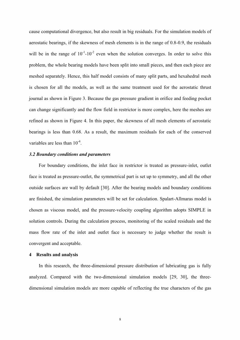
cause computational divergence, but also result in big residuals. For the simulation models of
aerostatic bearings, if the skewness of mesh elements is in the range of 0.8-0.9, the residuals
will be in the range of 10-1
-10-2
even when the solution converges. In order to solve this
problem, the whole bearing models have been split into small pieces, and then each piece are
meshed separately. Hence, this half model consists of many split parts, and hexahedral mesh
is chosen for all the models, as well as the same treatment used for the aerostatic thrust
journal as shown in Figure 3. Because the gas pressure gradient in orifice and feeding pocket
can change significantly and the flow field in restrictor is more complex, here the meshes are
refined as shown in Figure 4. In this paper, the skewness of all mesh elements of aerostatic
bearings is less than 0.68. As a result, the maximum residuals for each of the conserved
variables are less than 10-4
.
3.2 Boundary conditions and parameters
For boundary conditions, the inlet face in restrictor is treated as pressure-inlet, outlet
face is treated as pressure-outlet, the symmetrical part is set up to symmetry, and all the other
outside surfaces are wall by default [30]. After the bearing models and boundary conditions
are finished, the simulation parameters will be set for calculation. Spalart-Allmaras model is
chosen as viscous model, and the pressure-velocity coupling algorithm adopts SIMPLE in
solution controls. During the calculation process, monitoring of the scaled residuals and the
mass flow rate of the inlet and outlet face is necessary to judge whether the result is
convergent and acceptable.
4 Results and analysis
In this research, the three-dimensional pressure distribution of lubricating gas is fully
analyzed. Compared with the two-dimensional simulation models [29, 30], the three-
dimensional simulation models are more capable of reflecting the true characters of the gas
9
flow field in each position of bearing clearance. This is especially important when analyzing
the load characteristics of the aerostatic journal bearing.
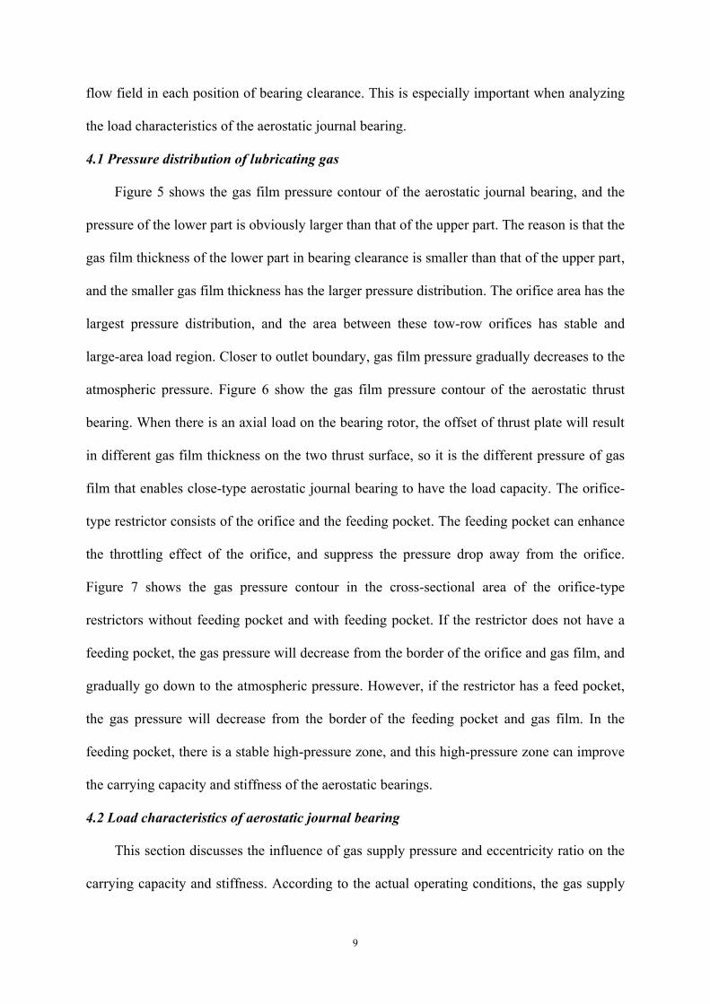
4.1 Pressure distribution of lubricating gas
Figure 5 shows the gas film pressure contour of the aerostatic journal bearing, and the
pressure of the lower part is obviously larger than that of the upper part. The reason is that the
gas film thickness of the lower part in bearing clearance is smaller than that of the upper part,
and the smaller gas film thickness has the larger pressure distribution. The orifice area has the
largest pressure distribution, and the area between these tow-row orifices has stable and
large-area load region. Closer to outlet boundary, gas film pressure gradually decreases to the
atmospheric pressure. Figure 6 show the gas film pressure contour of the aerostatic thrust
bearing. When there is an axial load on the bearing rotor, the offset of thrust plate will result
in different gas film thickness on the two thrust surface, so it is the different pressure of gas
film that enables close-type aerostatic journal bearing to have the load capacity. The orifice-
type restrictor consists of the orifice and the feeding pocket. The feeding pocket can enhance
the throttling effect of the orifice, and suppress the pressure drop away from the orifice.
Figure 7 shows the gas pressure contour in the cross-sectional area of the orifice-type
restrictors without feeding pocket and with feeding pocket. If the restrictor does not have a
feeding pocket, the gas pressure will decrease from the border of the orifice and gas film, and
gradually go down to the atmospheric pressure. However, if the restrictor has a feed pocket,
the gas pressure will decrease from the border of the feeding pocket and gas film. In the
feeding pocket, there is a stable high-pressure zone, and this high-pressure zone can improve
the carrying capacity and stiffness of the aerostatic bearings.
4.2 Load characteristics of aerostatic journal bearing
This section discusses the influence of gas supply pressure and eccentricity ratio on the
carrying capacity and stiffness. According to the actual operating conditions, the gas supply
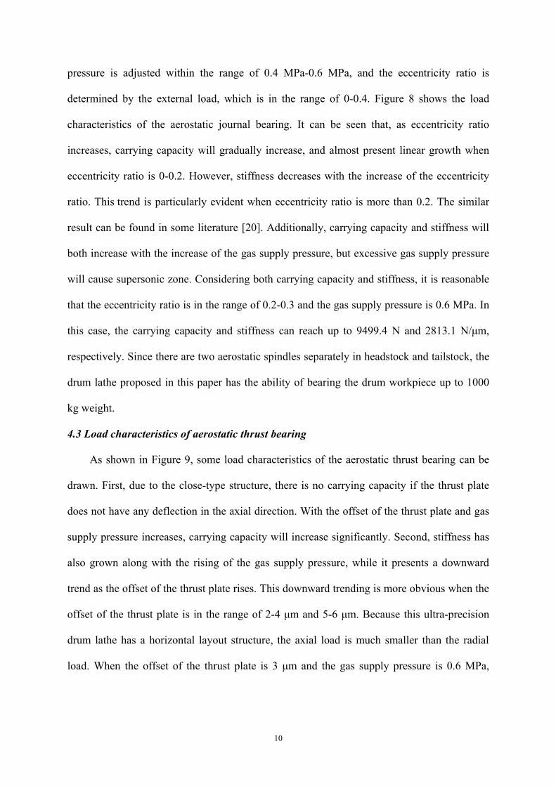
10
pressure is adjusted within the range of 0.4 MPa-0.6 MPa, and the eccentricity ratio is
determined by the external load, which is in the range of 0-0.4. Figure 8 shows the load
characteristics of the aerostatic journal bearing. It can be seen that, as eccentricity ratio
increases, carrying capacity will gradually increase, and almost present linear growth when
eccentricity ratio is 0-0.2. However, stiffness decreases with the increase of the eccentricity
ratio. This trend is particularly evident when eccentricity ratio is more than 0.2. The similar
result can be found in some literature [20]. Additionally, carrying capacity and stiffness will
both increase with the increase of the gas supply pressure, but excessive gas supply pressure
will cause supersonic zone. Considering both carrying capacity and stiffness, it is reasonable
that the eccentricity ratio is in the range of 0.2-0.3 and the gas supply pressure is 0.6 MPa. In
this case, the carrying capacity and stiffness can reach up to 9499.4 N and 2813.1 N/μm,
respectively. Since there are two aerostatic spindles separately in headstock and tailstock, the
drum lathe proposed in this paper has the ability of bearing the drum workpiece up to 1000
kg weight.
4.3 Load characteristics of aerostatic thrust bearing
As shown in Figure 9, some load characteristics of the aerostatic thrust bearing can be
drawn. First, due to the close-type structure, there is no carrying capacity if the thrust plate
does not have any deflection in the axial direction. With the offset of the thrust plate and gas
supply pressure increases, carrying capacity will increase significantly. Second, stiffness has
also grown along with the rising of the gas supply pressure, while it presents a downward
trend as the offset of the thrust plate rises. This downward trending is more obvious when the
offset of the thrust plate is in the range of 2-4 μm and 5-6 μm. Because this ultra-precision
drum lathe has a horizontal layout structure, the axial load is much smaller than the radial
load. When the offset of the thrust plate is 3 μm and the gas supply pressure is 0.6 MPa,
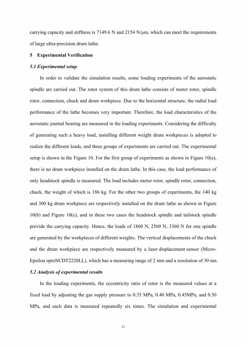
11
carrying capacity and stiffness is 7149.6 N and 2154 N/μm, which can meet the requirements
of large ultra-precision drum lathe.
5 Experimental Verification
5.1 Experimental setup
In order to validate the simulation results, some loading experiments of the aerostatic
spindle are carried out. The rotor system of this drum lathe consists of motor rotor, spindle
rotor, connection, chuck and drum workpiece. Due to the horizontal structure, the radial load
performance of the lathe becomes very important. Therefore, the load characteristics of the
aerostatic journal bearing are measured in the loading experiments. Considering the difficulty
of generating such a heavy load, installing different weight drum workpieces is adopted to
realize the different loads, and three groups of experiments are carried out. The experimental
setup is shown in the Figure 10. For the first group of experiments as shown in Figure 10(a),
there is no drum workpiece installed on the drum lathe. In this case, the load performance of
only headstock spindle is measured. The load includes motor rotor, spindle rotor, connection,
chuck, the weight of which is 186 kg. For the other two groups of experiments, the 140 kg
and 300 kg drum workpiece are respectively installed on the drum lathe as shown in Figure
10(b) and Figure 10(c), and in these two cases the headstock spindle and tailstock spindle
provide the carrying capacity. Hence, the loads of 1860 N, 2560 N, 3360 N for one spindle
are generated by the workpieces of different weights. The vertical displacements of the chuck
and the drum workpiece are respectively measured by a laser displacement sensor (Micro-
Epsilon optoNCDT2220LL), which has a measuring range of 2 mm and a resolution of 30 nm.
5.2 Analysis of experimental results
In the loading experiments, the eccentricity ratio of rotor is the measured values at a
fixed load by adjusting the gas supply pressure to 0.35 MPa, 0.40 MPa, 0.45MPa, and 0.50
MPa, and each data is measured repeatedly six times. The simulation and experimental
12
results are shown in Figure 11, where the lines depict the simulation values, and the discrete
points depict the experimental values. In general, the simulation results are in good
agreement with the experimental results. The maximum standard deviation is 0.011, and the
ratio of the maximum standard deviation to the corresponding mean value of eccentricity
ratio is within 6.6%. The maximum deviation of the simulation values and experimental
values is less than 15.3%. Therefore, the efficiency and accuracy of the simulation method
for calculating the load characteristics of aerostatic bearings has been experimentally proved.
6 Conclusions
This paper presents the design and analysis of an orifice-type aerostatic spindle with
high carrying capacity and stiffness used for a large ultra-precision drum lathe. The novel
three-dimensional simulation models of aerostatic journal bearing and aerostatic thrust
bearing are developed using Fluent, and the load characteristics of the aerostatic spindle are
studied. Finally, the experimental verification is carried out which proves that this simulation
method is feasible and can accurately calculate the load characteristics of the aerostatic
bearings. Based on the results of simulation and experimental studies, the conclusions can be
drawn as follows:
(1) The proposed three-dimensional simulation models can accurately reflect the gas flow
characteristics in bearing clearance.
(2) If the restrictor has a feeding pocket, the gas pressure will decrease from the border of the
feeding pocket and gas film. In feeding pocket, there is a stable high-pressure area, which
can suppress the pressure drop away from the orifice. Hence, the improved throttling
effect of orifice can enhance the load capacity and stiffness.
(3) For aerostatic journal bearing, it is reasonable that eccentricity ratio is in the range of 0.2-
0.3 and gas supply pressure is 0.6 MPa. In this case, carrying capacity and stiffness can
reach up to 9499.4 N and 2813.1 N/μm, which can meet the requirements of large ultra-
13
precision drum lathe.
Acknowledgement
The authors gratefully acknowledge the financial support of National Science and
Technology Major Project of High-end CNC Machine Tools and Basic Manufacturing
Equipment of China and the Aviation Science Foundation Project. The first author also would
like to thanks the EPSRC (EP/K018345/1) and University of Strathclyde to provide
sponsorship for the visiting research in the UK.
Funding
The research is supported by National Science and Technology Major Project of High-
end CNC Machine Tools and Basic Manufacturing Equipment of China (grant number
2011ZX04004-021); and the Aviation Science Foundation Project (grant number
20110877007).
References
1. Weck M, Fischer S and Vos M. Fabrication of microcomponents using ultraprecision
machine tools. Nanotechnol 1997; 8: 145-148.
2. Luo XC, Cheng K, Webb D, et al. Design of ultraprecision machine tools with
applications to manufacture of miniature and micro components. J Mater Process
Technol 2005; 167: 515-528.
3. Park CH, Song CK, Hwang J, et al. Development of an ultra precision machine tool for
micromachining on large surfaces. Int J Precis Eng Manuf 2009; 10: 85-91.
4. Lee JC, Gao W, Shimizu Y, et al. Precision measurement of carriage slide motion error of
a drum roll lathe. Precis Eng 2012; 36: 244-251.
5. Lee JC, Gao W, Shimizu Y, et al. Spindle error motion measurement of a large precision
roll lathe. Int J Precis Eng Manuf 2012; 13: 861-867.
14
6. Lee JC, Shimizu Y, Gao W, et al. Precision evaluation of surface form error of a large-
scale roll workpiece on a drum roll lathe. Precis Eng 2014; 38:839-848.
7. Wang MW, Tseng CC. Analysis and fabrication of a prism film with roll-to-roll
fabrication process. Opt Express 2009; 17: 4718-4725.
8. Ting CJ, Chang FY, Chen CF, et al. Fabrication of an antireflective polymer optical film
with subwavelength structures using a roll-to-roll micro-replication process. J Micromech
Microeng 2008; 18: 1-9.
9. Oh JS, Song CK, Hwang J, et al. An Ultra-precision Lathe for Large-area Micro-
structured Roll Molds. J Korean Soc Precis Eng 2013; 30: 1303-1312.
10. Moore Nanotechnology Systems. http://www.nanotechsys.com/machines/nanotech-hdl-
2000-horizontal-drum-lathe/.
11. Je TJ, Jeon EC, Park SC, et al. Improvement of machining quality of copper-plated roll
mold by controlling temperature variation. Trans Nonferrous Met Soc China 2011; 21:
37-41.
12. Liu ZS, Zhang GH, and Xu HJ. Performance analysis of rotating externally pressurized
air bearings. Proc IMechE Part J: J Engineering Tribology 2009; 223: 653-663.
13. Du JJ, Liu D, Zhang GQ, et al. Study of self-excited vibration for externally pressurized
gas thrust bearing with circumferential groove. Lubr Eng 2010; 35: 9-12.
14. Ye YX, Chen XD, Hu YT, et al. Effects of recess shapes on pneumatic hammering in
aerostatic bearings. Proc IMechE Part J: J Engineering Tribology 2010; 224: 231-237.
15. Yang DW, Chen CH, Kang Y, et al. Influence of orifices on stability of rotor-aerostatic
bearing system. Tribol Int 2009; 42: 1206-1219.
16. Yoshimoto S. Improvement of static characteristics of an aerostatic journal bearing using
the elastic deformation of an O-ring. Tribol Int 1987; 20: 290-296.
15
17. Fourka M and Bonis M. Comparison between externally pressurized gas thrust bearings
with different orifice and porous feeding systems. Wear 1997; 210: 311-317.
18. Yoshimoto S, Tozuka H and Dambara S. Static characteristics of aerostatic porous journal
bearings with a surface-restricted layer. Proc IMechE Part J: J Engineering Tribology
2003; 217: 125-132.
19. Panzera TH, Rubio JC, Bowen CR, et al. Microstructural design of materials for
aerostatic bearings. Cem Concr Compos 2008; 30: 649-660.
20. Du JJ, Zhang GQ, Liu T, et al. Improvement on load performance of externally
pressurized gas journal bearings by opening pressure-equalizing grooves. Tribol Int 2014;
73: 156-166.
21. Long W and Bao G. Entrance effect on load capacity of orifice compensated aerostatic
bearing with feeding pocket. Chin J Mech Eng 2010; 23: 1-9.
22. Fourka M, Tian Y and Bonis M. Prediction of the stability of air thrust bearings by
numerical, analytical and experimental methods. Wear 1996; 198: 1-6.
23. Belforte G, Raparelli T, Viktorov V, et al. Discharge coefficients of orifice-type restrictor
for aerostatic bearings. Tribol Int 2007; 40: 512-521.
24. Neves MT, Schwarz VA and Menon GJ. Discharge coefficient influence on the
performance of aerostatic journal bearings. Tribol Int 2010; 43: 746-751.
25. Dong ZG, Ding Y, Liu PK, et al. On the analysis of aerostatic thrust bearings with the
differential quadrature method. Proc IMechE Part J: J Engineering Tribology 2014; 228:
232-240.
26. Pande SS and Somasundaram S. Effect of manufacturing errors on the performance of
aerostatic journal bearings. Wear 1981; 66: 145-156.
27. Khalil MF and El-Shorbagy KA. Surface roughness effects on externally pressurized
bearing performance. Wear 1985; 103: 1-10.
16
28. Kwan YBP and Post JB. A tolerancing procedure for inherently compensated, rectangular
aerostatic thrust bearings. Tribol Int 2000; 33: 581-585.
29. Renn JC and Hsiao CH. Experimental and CFD study on the mass flow-rate characteristic
of gas through orifice-type restrictor in aerostatic bearings. Tribol Int 2004; 37: 309-315.
30. Li YT and Ding H. Influences of the geometrical parameters of aerostatic thrust bearing
with pocketed orifice-type restrictor on its performance. Tribol Int 2007; 40: 1120-1126.
17
Figure captions
Figure 1. Aerostatic spindle with orifice-type restrictors: (a) Internal structure of aerostatic
spindle; (b) Spindle sleeve; (c) Orifice-type restrictor with feeding pocket with D1 = 6 mm,
D2 = 4 mm, d=0.2 mm, h1= 0.5 mm, h2=0.2 mm.
Figure 2. Mesh model of aerostatic journal bearing.
Figure 3. Mesh model of aerostatic thrust bearing.
Figure 4. Refined meshes in orifice and feeding pocket.
Figure 5. Gas film pressure contour of aerostatic journal bearing, when gas supply pressure is
0.5 MPa, the eccentricity ratio is 0.3.
Figure 6. Gas film pressure contour of aerostatic thrust bearing, when gas supply pressure is
0.5 MPa, the offset of thrust plate is 3 μm.
Figure 7. Gas pressure contour of orifice-type restrictor: (a) Orifice-type restrictor without
feeding pocket; (b) Orifice-type restrictor with feeding pocket.
Figure 8. Load characteristics of aerostatic journal bearing: (a) Carrying capacity; (b)
Stiffness.
Figure 9. Load characteristics of aerostatic thrust bearing: (a) Carrying capacity; (b) Stiffness.
Figure 10. Experimental setup: (a) No drum workpiece installed on the lather; (b) A drum
workpiece of 140 kg installed on the lathe; (c) A drum workpiece of 300 kg installed on the
lathe.
Figure 11. Comparison of simulation values and experimental values: (a) Gas supply pressure
is 0.35 MPa; (b) Gas supply pressure is 0.40 MPa; (c) Gas supply pressure is 0.45MPa; (d)
Gas supply pressure is 0.5 MPa.
Table options
Table 1. Structural parameters of the aerostatic spindle.
Figure 1.Aerostatic spindle with orifice-type restrictors: (a) Internal structure of aerostatic spindle; (b)
Spindle sleeve; (c) Orifice-type restrictor with feeding pocket with D1 = 6 mm, D2 = 4 mm, d=0.2 mm, h1=
0.5 mm, h2=0.2 mm.
Figure 2
Figure 3
Figure 4
Figure 5
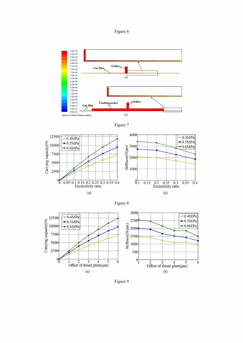
Figure 6
Figure 7
Figure 8
Figure 9
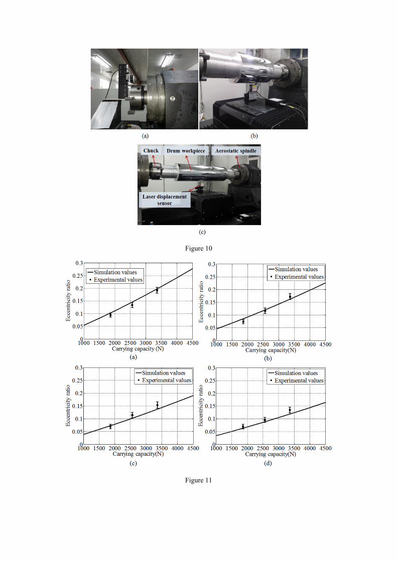
Figure 10
Figure 11