Embed Size (px)
Citation preview

Western Michigan University Western Michigan University
ScholarWorks at WMU ScholarWorks at WMU
Honors Theses Lee Honors College
4-15-2014
Design and Analysis of a Cold Gas Propulsion System for Design and Analysis of a Cold Gas Propulsion System for
Stabilization and Maneuverability of a High Altitude Research Stabilization and Maneuverability of a High Altitude Research
Balloon Balloon
Mitchell Brownell Western Michigan University, [email protected]
Follow this and additional works at: https://scholarworks.wmich.edu/honors_theses
Part of the Mechanical Engineering Commons
Recommended Citation Recommended Citation Brownell, Mitchell, "Design and Analysis of a Cold Gas Propulsion System for Stabilization and Maneuverability of a High Altitude Research Balloon" (2014). Honors Theses. 2396. https://scholarworks.wmich.edu/honors_theses/2396
This Honors Thesis-Open Access is brought to you for free and open access by the Lee Honors College at ScholarWorks at WMU. It has been accepted for inclusion in Honors Theses by an authorized administrator of ScholarWorks at WMU. For more information, please contact [email protected].

DESIGN AND ANALYSIS OF A COLD GAS PROPULSION SYSTEM FOR STABILIZATION AND
MANEUVERABILITY OF A HIGH ALTITUDE RESEARCH BALLOON
A thesis submitted in regards for partial fulfillment of the requirements of graduation applying to the degree program
Bachelor of Science in Engineering, B.S.E
Mechanical Engineering
Western Michigan University
College of Engineering & Applied Sciences
Department of Mechanical & Aerospace Engineering
Kalamazoo, Michigan USA 49008
Submitted By:
Mitchell B. Brownell
Gregory A. Neff
Ryan A. Savard
Tuesday, April 15, 2014

Design of a Cold Gas Propulsion System for a High Altitude Research Balloon | 2
Mitch Brownell | Ryan Savard | Greg Neff College of Engineering & Applied Sciences | Western Michigan University | Kalamazoo, Michigan USA
CREDENTIALS
Dr. Kristina Lemmer
Professor, Department of Mechanical & Aerospace Engineering
Senior Design Project Advisor & Chairperson
Mitchell B. Brownell
Mechanical Engineering Student, B.S.E
Design Team Member
Gregory A. Neff
Mechanical Engineering Student, B.S.E
Design Team Member
Ryan A. Savard
Mechanical Engineering Student, B.S.E
Design Team Member

Design of a Cold Gas Propulsion System for a High Altitude Research Balloon | 3
Mitch Brownell | Ryan Savard | Greg Neff College of Engineering & Applied Sciences | Western Michigan University | Kalamazoo, Michigan USA
TABLE OF CONTENTS
CREDENTIALS…………………………………………………………………………………………………..……………………………………….2
LIST OF FIGURES...……..…………………………………………………………………………....………………………………..…………….....4
LIST OF TABLES………………………………………………………………………………………………………….…………...………………..6
ABSTRACT………………………………………………………………………………………………………………………..……..………………….7
UNIVERSITY DISCLAIMER…………………...………………………………………………………………………………………..……….8
INTRODUCTION………………………………………………………………………………………………………….……………...……………...9
OBJECTIVE…………..……………………………………………………………...……………………………………………………………..……..10
INDUSTRY APPLICATION…………………………………...…………………………………………………………………..……...……..11
DESIGN REQUIREMENTS………………....…………………………………………………………………………………..……………….12
CONCEPT SELECTION EVALUATION MATRIX……………….…………………..……….…………………………….…….13
RESEARCH, SIMULATION, & MODELING…………………………………….…………………………………...……….……...14
GANTT CHART……………………………………………………………………………………………………….……………...………………...15
PERSONNEL & FACILITIES………………………..……………………………………………………….....………………….…………...16
COST ANALYSIS & COMPONENTS……………………..…………………………………………………...……...…………………..17
TANK DESIGN & SIMULATION……………………………………………………………………………………………...…………….18
NOZZLE ANALYSIS AND VALIDATION………………………………………………………………………………….…………31
FRAME ASSEMBLY DESIGN AND OPTIMIZATION…………………………………...………………………….…………41
OVERALL DESIGN ASSEMBLY OVERVIEW……………………………………………..……………………………………….46
VALIDATION METHODOLOGY………………………….………………………………………………………………...….…………...49
FURTHER RECOMMENDATIONS…………………………………………………...…………………………………….……………...50
CONCLUSION…………………………………………………………………………………………………………………..………...…………….51
REFERENCES………………………………………………………………………………………………………………..…...………………….….52
APPENDICES…....………………………………………………………………………………………………...……………...……………………...54
APPENDIX A – CONCEPT & SCHEDULE MATRICES ……...…………………………..………..……...…..…..55
APPENDIX B – TANK ANALYSIS MSDS/FEA RESULTS...……………………………………………....…….57
APPENDIX C – NOZZLE DESIGN & ANALYSIS CODE/FIGURES……………………………………….76
APPENDIX D – FRAME DESIGN ANALYSIS FIGURES……………………………………………………..…..80
APPENDIX E – MECHANICAL & AEROSPACE PROGRAM OUTCOMES……………..……..……..83
APPENDIX F – RESUMES………………………………………………………………………..... ………………………...……..95

Design of a Cold Gas Propulsion System for a High Altitude Research Balloon | 4
Mitch Brownell | Ryan Savard | Greg Neff College of Engineering & Applied Sciences | Western Michigan University | Kalamazoo, Michigan USA
LIST OF FIGURES
FIGURE 1 – THREE DIMENSIONAL RENDERINGS OF THE TANK CONCEPTS………..................…..…..22
FIGURE 2 – THEORETICAL REPRESENTATION OF STATIC LOADING WITHIN TANK..………......24
FIGURE 3 – OCTAHEDRAL (VON MISES) STRESS CRITERION…………………..……….……………………...…25
FIGURE 4 – VON MISES STRESSES OF TANK CONCEPT 1………………………………….………………………….26
FIGURE 5 – VON MISES STRESSES OF TANK CONCEPT 2……………………….………………………...…………..26
FIGURE 6 – VON MISES STRESSES OF TANK CONCEPT 3…………………………….……………………...………..27
FIGURE 7 – VON MISES STRESSES OF TANK CONCEPT 4……………………………………………....……………..27
FIGURE 8 – NOZZLE CROSS SECTION GEOMETRY…………………………………………..………..……….…..………34
FIGURE 9 – FLUID DENSITY OF NOZZLE…………………………………………………………………………....……...……...35
FIGURE 10 – FLUID TEMPERATURE WITHIN NOZZLE……………………………………...……………………...…….35
FIGURE 11 – MESH OF NOZZLE GEOMETRY…………………………………………………...………………………...……..36
FIGURE 12 – FLOW VELOCITY IN NOZZLE………………………………………………….……………….……………...……39
FIGURE 13 – FLUID PRESSURE IN NOZZLE…………………………………………………………………….…………...……39
FIGURE 14 – 3D RENDERING OF NOZZLE DESIGN………………………………………..….……………………………..40
FIGURE 15 – FINAL FRAME ASSEMBLY………………………………………………………...………..……...43
FIGURE 16 – OVERALL 3D VIEW OF COLD GAS PROPULSION SYSTEM…………………...………..……...46
FIGURE 17 – P&ID DIAGRAM OF DUAL THRUSTER SYSTEM…………………...………………………………….47
FIGURE 18 – DESIGN PROCESS GANTT CHART…………………………………………………………………...…………..56
FIGURE 19 – VON MISES STRESSES OF FEA TANK ANALYSIS………………………………...…………………..65
FIGURE 20 – 1ST PRINCIPAL STRESSES OF FEA TANK ANALYSIS…………………………………….....………65
FIGURE 21 – TOTAL DISPLACEMENT OF FEA TANK ANALYSIS………………………………………………....66
FIGURE 22 – 3RD PRINCIPAL STRESSES OF FEA TANK ANALYSIS………………………………………………66
FIGURE 23 – SAFETY FACTOR OF FEA TANK ANALYSIS…………...………………………………………....………67
FIGURE 24 – XX STRESSES OF FEA TANK ANALYSIS…………………...………………………………………...……..67
FIGURE 25 – YY STRESSES OF FEA TANK ANALYSIS…………………………...……………………………...………..68
FIGURE 26 – YZ STRESSES OF FEA TANK ANALYSIS…………………………………………………...………………..68
FIGURE 27 – ZZ STRESS OF FEA TANK ANALYSIS………………….…………………………………….………………..69
FIGURE 28 – XY STRESSES OF FEA TANK ANALYSIS……………...………………………………………...…………..69
FIGURE 29 – Z DISPLACEMENT OF FEA TANK ANALYSIS………………….………………………...………………70
FIGURE 30 – Y DISPLACEMENT OF FEA TANK ANALYSIS………………………………………………..……..…...70
FIGURE 31 – 1ST PRINCIPAL STRAIN OF FEA TANK ANALYSIS………………………………..…………….……71

Design of a Cold Gas Propulsion System for a High Altitude Research Balloon | 5
Mitch Brownell | Ryan Savard | Greg Neff College of Engineering & Applied Sciences | Western Michigan University | Kalamazoo, Michigan USA
FIGURE 32 – EQUIVALENT STRAIN OF FEA TANK ANALYSIS……………………….………………………........71
FIGURE 33 – XX STRAIN OF FEA TANK ANALYSIS……………………………….………………………….…………….72
FIGURE 34 – 3RD PRINCIPAL STRAIN OF FEA TANK ANALYSIS………………………………..……….………...72
FIGURE 35 – YY STRAIN OF FEA TANK ANALYSIS…………………………….…………………………….…………….73
FIGURE 36 – XZ STRAIN OF FEA TANK ANALYSIS………………………….……………………………….…………….73
FIGURE 37 – ZZ STRAIN OF FEA TANK ANALYSIS………………………….……………………………………….……..74
FIGURE 38 – YZ STRAIN OF FEA TANK ANALYSIS…………………………….………………………………….……….74
FIGURE 39 – XY STRAIN OF FEA TANK ANALYSIS……………………………….…………………………………….….75
FIGURE 40 – XZ STRAIN OF FEA TANK ANALYSIS…………………….………………………………………….……….75
FIGURE 41 – SHEAR STRESS MODEL OF NOZZLE………………….……………………………………...………………...78
FIGURE 42 – 3D LAYOUT OF FRICTION COEFFICIENT IN NOZZLE…..…………………………………………79
FIGURE 43 – TOTAL FEA FRAME DISPLACEMENTS……………………………………………………………….………80
FIGURE 44 – DEFORMATION OF FRAME STRUTS…………………………………………………………………..……….80
FIGURE 45 – MAXIMUM PRINCIPAL STRESS OF FRAME STRUT……………………....……………………..…..81
FIGURE 46 – SIDE VIEW OF PROPULSION SYSTEM ASSEMBLY……………………………………..…………...81
FIGURE 47 – TOP VIEW OF PROPULSION SYSTEM ASSEMBLY………………………………………..……….....82
FIGURE 48 – BOTTOM VIEW OF PROPULSION SYSTEM ASSEMBLY……………………..…………………...82

Design of a Cold Gas Propulsion System for a High Altitude Research Balloon | 6
Mitch Brownell | Ryan Savard | Greg Neff College of Engineering & Applied Sciences | Western Michigan University | Kalamazoo, Michigan USA
LIST OF TABLES
TABLE 1 – TABLE OF COMPONENTS FOR CGPS DESIGN……………………………………………………………...17
TABLE 2 – PROPERTIES OF NITROGEN GAS AT 275.8 BAR, -60 DEGREES C…………………....………..19
TABLE 3 – TANK CONCEPT CHARACTERISTIC SUMMARY………………………………………….……………...21
TABLE 4 – MATERIAL PROPERTIES FOR TANK CONCEPTS…………………………………………………..……..23
TABLE 5 – SUMMARIZATION OF SAFETY FACTORS FOR TANK CONCEPTS……………………...……29
TABLE 6 – NOZZLE CONCEPTS SUMMARIZATION………………………………………………………...……………....33
TABLE 7 – CFD ANALYSIS ENVIRONMENT/PARAMETERS……………………………………...…..………………36
TABLE 8 – CALCULATION RESULTS OF NOZZLE CHARACTERISTICS……………………...………………37
TABLE 9 – MATERIAL PROPERTY TABLE INCLUDING FRAME MASS…..………………….……………51
TABLE10 – OVERALL MASS PROPERTY SUMMARY…………………………..…………………………….……………51
TABLE 11 – CONCEPT SELECTION MATRIX……………………………………………………………………………………..58
TABLE 12 – PHYSICAL PROPERTIES OF CARBON FIBER TANK……………………………………..………........63
TABLE 13 – SUMMARY OF FEA OF TANK………………………………………………………………………………………....63
TABLE 14 – FEA TANK DETAILS………………………………………………………………………………….……………………...63
TABLE 15 – MATERIAL PROPERTY SUMMARY…………………………………………………….…………………………63
TABLE 16 – RESULTANT FORCES & MOMENTS……………………………………………………………………………...63
TABLE 17 – SUMMARY OF STRESS/STRAIN RESULTS………………………………………..…………………………64
Design of a Cold Gas Propulsion System for a High Altitude Research Balloon | 7
Mitch Brownell | Ryan Savard | Greg Neff College of Engineering & Applied Sciences | Western Michigan University | Kalamazoo, Michigan USA
ABSTRACT
The purpose of this research project was to develop and create a design for a cold gas propulsion
system which will maneuver and stabilize a high altitude research balloon while proposing an inexpensive,
light weight design that researchers can reproduce. The methodology to the design of this system was based
on factors that are all dependent upon one another. The parameters that directed the decisions made
throughout this design project were the thrust needed to rotate the unit, and the allowable weight permitted
by federal regulations. The frame was designed with a gas storage system, gas transmission system, and
nozzle assembly which was integrated into a single unit with allocated room for cameras and sensors. The
conditions within the tank, storage system, and nozzles were determined by designing a converging nozzle
while also determining the correct pressure and flow rate to sustain a desired thrust impulse. The design
was validated using Autodesk Simulation CFD and ANSYS for the nozzle design and Autodesk’s Inventor
software for the structural analysis of the tank. The design and validation of the frame was done using
Solidworks design software and ANSYS, respectively. The value of this project is to aid in the
reconnaissance and analysis of high altitude conditions as well as provide a stable and controllable platform
for testing equipment that can be ultimately applied to space applications.

Design of a Cold Gas Propulsion System for a High Altitude Research Balloon | 8
Mitch Brownell | Ryan Savard | Greg Neff College of Engineering & Applied Sciences | Western Michigan University | Kalamazoo, Michigan USA
UNIVERSITY DISCLAIMER
This project was accomplished by mechanical engineering students in partial fulfillment of a
Mechanical Engineering Bachelor’s Degree through the College of Engineering & Applied Sciences at
Western Michigan University in Kalamazoo, Michigan USA. The University nor the design team make any
claims to the accuracy of the information nor accept responsibility for those choosing to use the information
contained here within. The components and prototypes within were built, assembled, modeled, and tested
by undergraduate students. Operators of any equipment pertaining to the design do so at their own risk and
accept responsibility for any injuries or deaths that may occur. Western Michigan University and the
members of the undergraduate design team are not responsible for any damages or injuries that occur.

Design of a Cold Gas Propulsion System for a High Altitude Research Balloon | 9
Mitch Brownell | Ryan Savard | Greg Neff College of Engineering & Applied Sciences | Western Michigan University | Kalamazoo, Michigan USA
INTRODUCTION
The project that the undergraduate senior design team was presented with was with regard to a cold
gas propulsion system for applications regarding high altitude research balloons. The project was given to
the team by Department of Mechanical & Aerospace Engineering Faculty Member, Dr. Kristina Lemmer.
The need for this design project extended to the unmet needs of many companies and researchers that are
interested in obtaining data from the upper atmosphere. This data included weather data, space research and
exploration, and also chemical analysis of the ozone layer and upper-atmospheric gases. The design team
created a design for a propulsion system that can be operated remotely, in low pressure conditions that
allowed for maneuverability and stabilization of a high altitude research balloon. The design team utilized
Autodesk Simulation Computational Fluid Dynamics (CFD) and ANSYS software to correctly model a
thruster nozzle, which was determined to be a converging nozzle. Also calculated was the inlet and outlet
conditions to produce a calculated value of thrust of 0.0247 N, including mass flow rate, inlet pressure, inlet
and outlet velocities, and also cross sectional areas of the inlet and outlet of the nozzle. After design
simulation, the team conducted FEA analysis using Autodesk Inventor to analyze and design the frame,
propellant tank, and propellant nozzle. After the system was designed in Autodesk and analyzed in CFD, a
recommendation and outline of a testing system was created regarding the designed nozzle and propellant
tank and feed lines that will provide the designed operating conditions for the nozzle to create the desired
amount of thrust.
Design of a Cold Gas Propulsion System for a High Altitude Research Balloon | 10
Mitch Brownell | Ryan Savard | Greg Neff College of Engineering & Applied Sciences | Western Michigan University | Kalamazoo, Michigan USA
OBJECTIVE
To design, analyze and validate a cold gas propulsion system for a high altitude research balloon
allowing for balloons to be maneuvered and stabilized at high altitudes. The system will be utilized for
stratospheric data acquisition regarding weather and chemical analysis. The design team utilized CAD, FEA,
and CFD modeling programs to successfully design a propulsion system for a desired amount of thrust
while minimizing the total mass of the system to optimize the maneuverability characteristics. The nozzle
and system will then be used to create a recommendation and outline for future testing processes and
prototyping of the proposed propulsion system.

Design of a Cold Gas Propulsion System for a High Altitude Research Balloon | 11
Mitch Brownell | Ryan Savard | Greg Neff College of Engineering & Applied Sciences | Western Michigan University | Kalamazoo, Michigan USA
INDUSTRY APPLICATION
High altitude research is of great importance in a world with an ever growing population, focused
on preserving the environment and enhancing the ability to better predict weather conditions. With the
design and implementation of the cold gas propulsion system it will be possible to maintain heading and
positioning while at altitude. The action is crucial for scientific testing and measuring of greenhouse gas
emissions at high altitude as well as monitoring weather patterns. Cold gas propulsion is an inexpensive
and practical solution for providing surveillance, topography maps and scanning to farmers, or embattled
countries. The main industrial need for a cold gas propulsion system is it provides a relatively low cost yet
effective way of maneuvering a high altitude balloon once at altitude for university and metrological
research purposes.

Design of a Cold Gas Propulsion System for a High Altitude Research Balloon | 12
Mitch Brownell | Ryan Savard | Greg Neff College of Engineering & Applied Sciences | Western Michigan University | Kalamazoo, Michigan USA
DESIGN REQUIREMENTS
To develop the new design, constraints were considered which directed the development of the
design to the correct solution. With the design project, there were various factors that weighed into the
success and validation of the project. According to the Federal Aviation Administration (FAA), a balloon
launch cannot have a payload exceeding a total of 2.72 kg. A balloon can carry a total of 5.44 kilograms
but not as one payload. This limited the design of the propulsion system and its components to a maximum
weight of 2.72 kg. A goal was set to limit the mass of the propulsion system, including frame, and control
system to conform to the regulated mass and total approximately 2.26 kg. This additional 0.46 kg was
allocated to researchers who have sensors and other data acquisition equipment to affix to the unit. With
the entire system designed to be less than 2.72 kg, the propulsion system must be able to provide enough
thrust to provide adequate stability and maneuverability of the unit. A force was determined to be an
adequate amount of force to rotate a six pound or 2.72 kg unit. The value of force, which was determined
to be 0.02547 N, outlined in the Nozzle Design section, was also chosen based on the characteristics of the
nozzle being designed. The nozzles must be small enough to not add significant weight but still efficiently
accelerate the gas to the appropriated thrust. The mass flow rate, inlet pressure and nozzle dimensions were
settled upon simultaneously to provide an exit velocity that provided the desired thrust value. These values
were checked to make sure the system can handle these conditions and would not add significant weight.

Design of a Cold Gas Propulsion System for a High Altitude Research Balloon | 13
Mitch Brownell | Ryan Savard | Greg Neff College of Engineering & Applied Sciences | Western Michigan University | Kalamazoo, Michigan USA
CONCEPT SELECTION EVALUATION MATRIX
To initially evaluate and validate the preliminary design ideas and requirements, a concept selection
matrix was created. This matrix accompanies design requirements and considerations with four different
concepts for the propulsion system. The concept selection matrix is a dynamic diagram that includes the
design considerations on the vertical columns (Y-axis), and the concepts on the horizontal columns (X-
axis). The design considerations have designated weighting factors to provide an appropriated total weight
factor for certain parameters that will have a more significant influence on the design process, or how the
testing/construction will occur. There are two sub-categories for the final overall ‘score’ of each concept.
Within each of these sub-categories, there are individually evaluated items that feed into the sub-category
scores. This then feeds into the overall score of the concept. The parameters included in the Cost/Quality
category are: Manufacturability/Feasibility of Production and Gas Delivery System. The parameters that
were included within the Geometric/Design sub-category were: Thrust Maximization, Design
Considerations, and Geometric Characteristics. As mentioned, each parameter carries different weight
factors which help evaluate each concept allowing for the selection of an ideal final concept. The highest
score for the four evaluated concept was 82.91/100.00. The other concepts scored a 73.00/100.00 or below.
The design concept that achieved the highest evaluation score is a converging, custom propellant tank
design, which is what the design team has chosen to purse. This concept selection matrix was a live, working
document that will be changed (if needed) during our design process and while the concept is being
evaluated to keep an open mind about any of the possible design parameters that can be included. Please
see Table 11 in Appendix A for the Concept Selection Matrix.

Design of a Cold Gas Propulsion System for a High Altitude Research Balloon | 14
Mitch Brownell | Ryan Savard | Greg Neff College of Engineering & Applied Sciences | Western Michigan University | Kalamazoo, Michigan USA
RESEARCH, SIMULATION, & MODELING OVERVIEW
The cold gas propulsion system was analyzed in computational software to ensure that the results
that are to be attained are achieved in the design process. Since the propulsion system utilized properties of
gas dynamics, computational fluid dynamics (CFD) was used with a program called ANSYS Fluent. This
program ensured that the proper gas characteristics were attained within the tank, through the flow delivery
system, and towards the atmosphere through the nozzle. The CFD program had the ability to model the
mass flow rate of the gas based on pressure, density, and other gas characteristics. The CFD program also
validated laminar flow within the nozzle to ensure optimum thrust values with respect to the amount of fuel
used.
Also, the entire designed system was modeled within Autodesk Inventor. This program allowed for
proper geometric modeling of the cold gas propulsion system, and allowed for instantaneous design changes
as research was done in order to update the existing model. The cold gas propulsion system was completely
modeled to ensure proper geometric fits and tolerances of the model. The Inventor software also had the
ability for finite element analysis, which allowed for the design team to properly evaluate the forces within
the propulsion system structure, the forces within the tank, and also the forces and other stresses on the
nozzle. This FEA analysis was crucial to the success of the design as it allowed the design team to minimize
the weight of the components, while still maintaining structural rigidity.

Design of a Cold Gas Propulsion System for a High Altitude Research Balloon | 15
Mitch Brownell | Ryan Savard | Greg Neff College of Engineering & Applied Sciences | Western Michigan University | Kalamazoo, Michigan USA
GANTT CHART
The senior design project, alike many engineering projects, was tracked using a strict time schedule
that ensured proper completion. This time frame was tracked using a Gantt chart. The Gantt chart, as seen
in Figure 18 in Appendix A, provided a visual model for the design and design planning process. The Gantt
chart that the design team produced included a time schedule for the modeling, design, analysis, and report
writing. The Gantt chart served as a dynamic baseline, meaning it was changed slightly when the design
process was on a different schedule, or things happened to change in the schedule, and so forth. The Gantt
chart was first sculpted in the preliminary design process of the project which provided a rough outline and
estimate of the process in which the project would be completed.

Design of a Cold Gas Propulsion System for a High Altitude Research Balloon | 16
Mitch Brownell | Ryan Savard | Greg Neff College of Engineering & Applied Sciences | Western Michigan University | Kalamazoo, Michigan USA
PERSONNEL & FACILITIES
The facilities and personnel required for successful completion of this senior design project can all
be found within Western Michigan University. Personnel that were referenced throughout the process are
Dr. Kristina Lemmer, the design group’s faculty mentor, Mike Conkell, graduate assistant machinist in the
College of Engineering and Applied Science, and Peter Thannhauser, lab technician and LabView specialist.
Other acknowledgements for the design project include Dr. Jenifer Hudson, who provided support and
information to the project as well as sat on the Lee Honors College Thesis Defense Committee for Mr.
Brownell. Dr. Javier Montefort-Sanchez who provided the team with resources for thrust and nozzle
calculations. Facilities that were utilized by the design team include the Aerospace Laboratory for Plasma
Experiments where modeling, concept check testing, and other validation occurred. The ALPE lab also
allowed the design team facilities and other help for the design project and process. Other facilities utilized
throughout the project were the Student Projects Lab, the Computer Aided Engineering (CAE) center, and
numerous laboratories throughout the University.

Design of a Cold Gas Propulsion System for a High Altitude Research Balloon | 17
Mitch Brownell | Ryan Savard | Greg Neff College of Engineering & Applied Sciences | Western Michigan University | Kalamazoo, Michigan USA
COST ANALYSIS & COMPONENTS
Below in Table 1 is a summarization of many of the anticipated components that the design team
considered for testing. Included are the necessary materials for construction of a proof of concept propulsion
system. Although the design project did not include a physical build and test of the propulsion system, the
recommendation of materials and components can be made for future projects. The financial impact figures
are also tentatively listed next to the individual components.
Table 1 – Table of Components for CGPS Design
Component Quantity Price($) Total($)
Mass Flow Reader 1 250.00 250.00
Needle valve 1 110.72 110.72
Gas Solenoid Valve HP 2 551.00 1102.00
Piping 10 (ft) 5.00 50.00
Fittings 10 10.00 100.00
1.5in 303 stainless steel bar stock 1 49.19 49.19
Compressed N2 Tank 1 60.00 60.00
4000 psi Tank 1 600.00 600.00
80/20 8ft Extrusion 1 19.00 19.00
80/20 BHSCS 24 0.61 14.64
80/20 1/4in T-nut 24 0.30 7.20
80/20 2-Hole Inside corner Bracket 12 2.90 34.80
Total $2,399

Design of a Cold Gas Propulsion System for a High Altitude Research Balloon | 18
Mitch Brownell | Ryan Savard | Greg Neff College of Engineering & Applied Sciences | Western Michigan University | Kalamazoo, Michigan USA
TANK DESIGN AND SIMULATION
Gas Properties
The cold gas propulsion system that was designed by the design team included a custom engineered
cold gas tank, which was an integral part of the propulsion system. The tank was, in theory, the power plant
of the propulsion system as it contained the fuel necessary for the propulsion system to apply thrust, which
provided a moment around the z-axis of the entire unit to rotate and provide a yaw positioning system. The
design team recognized the need for a tank to withstand high pressures, yet allowing for minimization of
weight in order to allow for payload for the nozzles, frame, sensors, and other gas delivery components of
the gas to produce thrust.
The process gas for the overall system design was chosen to be Nitrogen. The nitrogen process gas
was chosen for numerous reasons, including it characteristics and behavior with air as well as its relation to
the atmosphere. A main reason for the selection of the nitrogen gas within our system is that it is not reactive
at all with air and its components, since the air that is found in Earth’s atmosphere is nearly 78% nitrogen
gas. Nitrogen was also chosen as the propellant in the system due to its molecular weight, as a nitrogen
molecule weights roughly 28 grams/mole. This allows the gas from the nozzle to produce a thrust according
to the conservation of momentum as the gas (with a mass) exits our control volume. Nitrogen is also a
colorless, odorless and tasteless gas that provides no harm to the atmosphere and its constituents. This plays
a key role in the extent of any ethical issues that this propulsion system may create in regards to pollution
or harm to the environment. The abundance of nitrogen and its availability are also an important
characteristic. Nitrogen is readily available for purchase through many scientific gas supply companies
locally which allows for a financial benefit.
Design of a Cold Gas Propulsion System for a High Altitude Research Balloon | 19
Mitch Brownell | Ryan Savard | Greg Neff College of Engineering & Applied Sciences | Western Michigan University | Kalamazoo, Michigan USA
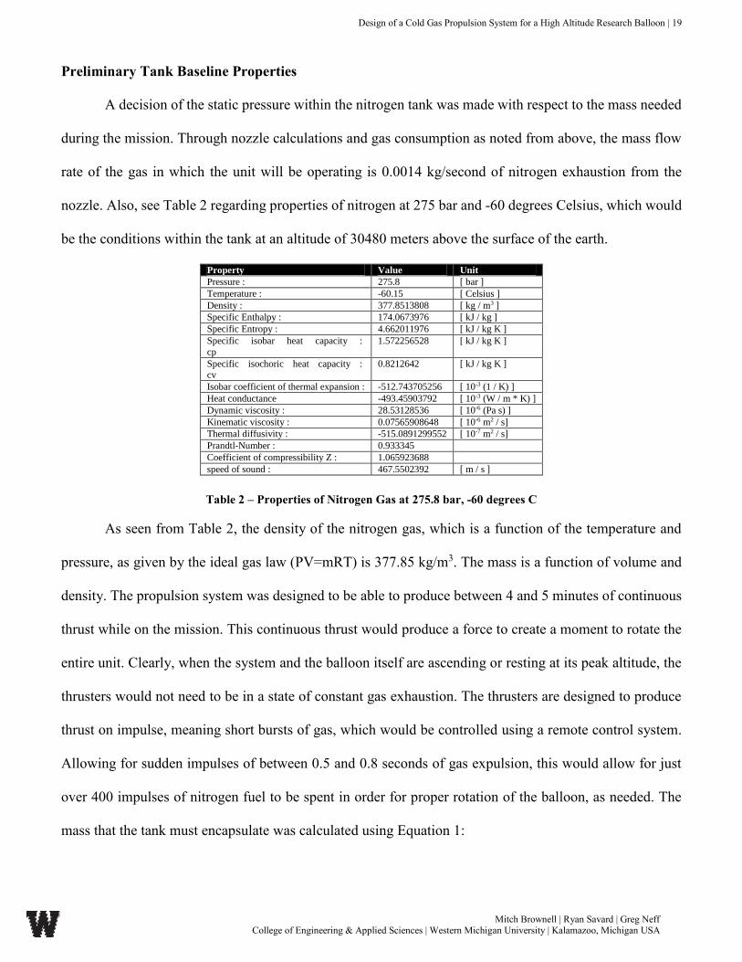
Preliminary Tank Baseline Properties
A decision of the static pressure within the nitrogen tank was made with respect to the mass needed
during the mission. Through nozzle calculations and gas consumption as noted from above, the mass flow
rate of the gas in which the unit will be operating is 0.0014 kg/second of nitrogen exhaustion from the
nozzle. Also, see Table 2 regarding properties of nitrogen at 275 bar and -60 degrees Celsius, which would
be the conditions within the tank at an altitude of 30480 meters above the surface of the earth.
Property Value Unit
Pressure : 275.8 [ bar ]
Temperature : -60.15 [ Celsius ]
Density : 377.8513808 [ kg / m3 ]
Specific Enthalpy : 174.0673976 [ kJ / kg ]
Specific Entropy : 4.662011976 [ kJ / kg K ]
Specific isobar heat capacity :
cp
1.572256528 [ kJ / kg K ]
Specific isochoric heat capacity : cv
0.8212642 [ kJ / kg K ]
Isobar coefficient of thermal expansion : -512.743705256 [ 10-3 (1 / K) ]
Heat conductance -493.45903792 [ 10-3 (W / m * K) ]
Dynamic viscosity : 28.53128536 [ 10-6 (Pa s) ]
Kinematic viscosity : 0.07565908648 [ 10-6 m2 / s]
Thermal diffusivity : -515.0891299552 [ 10-7 m2 / s]
Prandtl-Number : 0.933345
Coefficient of compressibility Z : 1.065923688
speed of sound : 467.5502392 [ m / s ]
Table 2 – Properties of Nitrogen Gas at 275.8 bar, -60 degrees C
As seen from Table 2, the density of the nitrogen gas, which is a function of the temperature and
pressure, as given by the ideal gas law (PV=mRT) is 377.85 kg/m3. The mass is a function of volume and
density. The propulsion system was designed to be able to produce between 4 and 5 minutes of continuous
thrust while on the mission. This continuous thrust would produce a force to create a moment to rotate the
entire unit. Clearly, when the system and the balloon itself are ascending or resting at its peak altitude, the
thrusters would not need to be in a state of constant gas exhaustion. The thrusters are designed to produce
thrust on impulse, meaning short bursts of gas, which would be controlled using a remote control system.
Allowing for sudden impulses of between 0.5 and 0.8 seconds of gas expulsion, this would allow for just
over 400 impulses of nitrogen fuel to be spent in order for proper rotation of the balloon, as needed. The
mass that the tank must encapsulate was calculated using Equation 1:

Design of a Cold Gas Propulsion System for a High Altitude Research Balloon | 20
Mitch Brownell | Ryan Savard | Greg Neff College of Engineering & Applied Sciences | Western Michigan University | Kalamazoo, Michigan USA
𝑚𝑎𝑠𝑠 = 𝑚𝑎𝑠𝑠 𝑓𝑙𝑜𝑤 𝑟𝑎𝑡𝑒(𝑑𝑒𝑠𝑖𝑟𝑒𝑑 𝑡ℎ𝑟𝑢𝑠𝑡 𝑡𝑖𝑚𝑒) = (0.0014𝑘𝑔
𝑚3) (240 𝑠𝑒𝑐𝑜𝑛𝑑𝑠)
= 0.336 𝑘𝑔 𝑜𝑓 𝑁2 𝑔𝑎𝑠
(Eqn.1)
Based on the two independent variables from above (mass flow rate of the gas and desired thrust
time), this would allow for a general calculation of the mass of the nitrogen that would be needed for a
single mission of the balloon flight. Since this number would be the baseline for the tank, a volume
calculation could be obtained using the relationship between mass, density and volume. The above figure
displays the properties of nitrogen gas as a function of the designed pressure and temperature. The following
Equation 2 can be referenced to obtain a geometrical relationship for the volume of the tank that is needed.
𝐴𝑝𝑝𝑟𝑜𝑥𝑖𝑚𝑎𝑡𝑒 𝑉𝑜𝑙𝑢𝑚𝑒 =𝐷𝑒𝑠𝑖𝑔𝑛𝑒𝑑 𝑀𝑎𝑠𝑠
𝐷𝑒𝑛𝑠𝑖𝑡𝑦 𝑎𝑡 𝐷𝑒𝑠𝑖𝑔𝑛𝑒𝑑 𝐶𝑜𝑛𝑑𝑖𝑡𝑖𝑜𝑛𝑠=
0.336 𝑘𝑔
377.85 𝑘𝑔/𝑚3= 8.89𝑥10−4 𝑚3
(Eqn.2)
This calculated volume of 8.89𝑥10−4cubic meters, or 0.88924 liters, allowed for a baseline
volume needed for the proper amount of thrust time within the propulsion system mission. This volume
criteria was crucial in developing the frame and tank size that would be proper for the mission
requirements.
Tank Concepts
Multiple concepts were completed and numerous designs were considered for the custom tank in
which would be used for the final design. From the nozzle analysis through computational fluid dynamics
and nozzle geometry, the mass flow rate and the volume needed, multiple tank geometries, shapes, concepts,
and materials were considered for final use of the tank. The needed properties of the tank consisted of the
following:
Strong material with respect to static, tensile loading
Lightweight material

Design of a Cold Gas Propulsion System for a High Altitude Research Balloon | 21
Mitch Brownell | Ryan Savard | Greg Neff College of Engineering & Applied Sciences | Western Michigan University | Kalamazoo, Michigan USA
High strength to weight ratio
A material with compatibility of tank formation and manufacturing
Low stress concentrators in the corners of the tank (fillets and chamfers)
Compact design, ability to conserve volume and assembly within frame
High safety factor due to high pressure static loading of tank
These properties and requirements allow for numerous designs of the tank to be considered and
analyzed for stress characteristics and other loading. The following table summarizes four tank concepts
that were considered, along with basic properties and geometries.
Table 3 – Tank Concept Characteristic Summary
Table 3 above shows the relationships and different properties of the tank designs, which include 4
different concepts. The tank concepts vary from the wall thickness of the tank, to the material used, the
overall physical geometry of the tank, as well as the volume. The volume of the tank concepts are relatively
consistent, as the analysis and usage for all 4 tanks are consistent. This is due to the fact that the tanks will
have the same application and same loading from within due to the static 285 bar pressure load from the
nitrogen gas. Figure 1 on the following page displays the three dimensional renderings of the 4 tank concepts,
which vary from a square filleted design, to a spherical, and thicker tank design.
Tank Concept Number 1 2 3 4
Overall Length (cm) 16.54 17.78 14.22 15.24
Overall Diameter (cm) 10.16 10.16 12.95 10.16
Gas Displacement Volume (cm^3) 1139.57 1065.94 1145.22 1056.43
Volume of Tank (cm^3) 155.56 140.26 140.05 141.49
Volume Inefficiency (%) 13.65 13.16 12.23 13.39
Tank Material Carbon Fiber Carbon Fiber 304 Stainless Steel Titanium
Wall thickness (cm) 0.25 0.13 0.25 0.25
Density of Tank Material (kg/m^3) 1771.00 1771.00 8050.00 4506.00
Mass of Tank (without gas) (kg) 0.28 0.25 1.13 0.64

Design of a Cold Gas Propulsion System for a High Altitude Research Balloon | 22
Mitch Brownell | Ryan Savard | Greg Neff College of Engineering & Applied Sciences | Western Michigan University | Kalamazoo, Michigan USA
Figure 1 – Three Dimensional Renderings of Tank Concepts
Figure 1 above shows the geometries of the tank vary based on the design and the thickness, diameter,
and overall length. Tank concept number one utilizes a concave bottom portion of the tank, which serves
as a rigid support that will allow for higher pressures to be withstood within the structure. This tank has a
semi-circular upper region that allows for even stress concentrations throughout. The tank concept number
2 utilizes basic hemispherical shapes on the top and bottom of the tank, which like concept 1, allows for the
stress concentrators to be small and for the pressure vessel to hold a considerable amount of weight as
compared to that with sharp corners. The third tank concept utilizes a completely spherical design. Although
the stress concentration factors are low, this design does produce some concern in terms of
manufacturability as well as it is vastly more robust than the other designs. The fourth tank concept utilized
Tank Concept 1 Tank Concept 2
Tank Concept 3 Tank Concept 4

Design of a Cold Gas Propulsion System for a High Altitude Research Balloon | 23
Mitch Brownell | Ryan Savard | Greg Neff College of Engineering & Applied Sciences | Western Michigan University | Kalamazoo, Michigan USA
a much simpler, easier-to-manufacture design. This concept utilized more straight lines and relied less on
the hemispherical designs as the first three concepts did. All three tank concepts provide a significant
amount of volume for storage of the gas at high pressure. The question of which concept to select comes
down to the material strength of each tank concept, and whether or not the material can withstand the
pressure applied (285 bar) within the tank.
All 4 concepts of the tank design were completed within a Finite Element Analysis program. The
program utilized for the purpose of this project was Autodesk Inventor, which allows the user to analyze
static, dynamic, rotational, and point loads on any surface. The program inputs material properties and
loading conditions and results in graphical outputs of stress and displacement of the material. Needed for
the FEA analysis are the material properties of the various materials so the FEA program can compute the
overall stress levels, etc. The following table is the summary of the tank concept materials and their
respective material properties.
Table 4 – Material Properties for Tank Concepts
The tank concepts are dependent on the material properties of the tank, regarding the safety factor
and the stresses. As seen in Table 4 the 304 Stainless Steel and the Titanium are isotropic in respect to the
material behavior. This meaning that the material properties of the 304 and Titanium differ, almost
negligibly, in the X, Y, and Z directions. This gives way to uniformity of the resulting forces and safety
factors within the materials. Carbon fiber, conversely, does not exhibit isotropic material properties. Carbon
Property: Thermal Conductivity (W/m*K) Specific Heat (J/kg*K) Thermal Expansion Coefficient (1/K)
Stainless Steel 2.02 460.24 0.0000104
Carbon Fiber 0.105 154.808 0.000013889
Titanium 1.37 502.08 0.0000086
Property: Youngs Modulus (GPa) Poisson's Ratio Behavior Mode
Stainless Steel 206.7 0.27 Isotropic
Carbon Fiber 275.1 0.1 Orthotropic
Titanium 102.8 0.36 Orthotropic
Property: Density (kg/m^3) Yield Strength (MPa) Tensile Strength (MPa)
Stainless Steel 8050 688.9 861.1
Carbon Fiber 1771 3375 4143
Titanium 4506 275.5 344.5
Material Properties
Isotropic

Design of a Cold Gas Propulsion System for a High Altitude Research Balloon | 24
Mitch Brownell | Ryan Savard | Greg Neff College of Engineering & Applied Sciences | Western Michigan University | Kalamazoo, Michigan USA
fiber is orthotropic, meaning that the material properties of carbon fiber differ in every direction, with
respect to the X, Y, and Z axes. The selection of isotropic and orthotropic can be selected within Autodesk
Inventor FEA, so the program can model the behavior of the material with respect the orientation of its
fibers, etc. The FEA program must input the material properties of carbon fiber in each direction (X,Y, and
Z) in order to have a proper analysis of the material as compared to the isotropic behavior.
Below is an example of the static loading which was placed on the entire interior surface area of
the tank. This loading represents static pressure that is uniformly acting on the entire surface within the tank.
This uniform pressure is a static loading due to the uniform 285 bar pressure exerted by the gas. The FEA
simulation was ran with this static loading condition only since it was the dominant loading that the
component experienced.
Figure 2 – Theoretical Representation of Static Loading Within Tank Concepts
Figure 2 above represents the loading that the FEA program uses as an input to calculate the stresses,
strains, displacements and safety factors of the different tank concepts. Although the geometries are
different, the loading (load per unit area) is the same as all tanks are analyzed using the same mission
requirements and conditions.
Figures 4, 5, 6, and 7 are the result of static FEA analysis for the four separate tank concepts. These
figures display the Von Mises resultant stresses within the tank concepts. These Von Mises stresses
represent the overall stress values from the stresses in the X, Y, and Z directions. The Von Mises stress is

Design of a Cold Gas Propulsion System for a High Altitude Research Balloon | 25
Mitch Brownell | Ryan Savard | Greg Neff College of Engineering & Applied Sciences | Western Michigan University | Kalamazoo, Michigan USA
calculated by combining the stresses in the three dimensions into one number that is compared with the
materials yield strength. This allows the FEA program to compute, even with a complex geometry, the
stress of the material at a certain point as well as safety factors, etc. This Von Mises stress also utilized the
octahedral stress criterion when comparing materials and the point at which they fracture. The octahedral
stress criterion, which are from the loadings due to the stresses along the axis in the body that is being
loaded, is an accurate way to depict the stresses within a material, when the maximum normal stress
criterion (MNS) and maximum shear stress criterion (MSS) do not apply. Refer to Figure 3 below for the
depiction of the Von Mises stress on the graph, along with the MSS and MNS stress failure criterion.
Figure 3 – Octahedral (Von Mises) Stress Criterion

Design of a Cold Gas Propulsion System for a High Altitude Research Balloon | 26
Mitch Brownell | Ryan Savard | Greg Neff College of Engineering & Applied Sciences | Western Michigan University | Kalamazoo, Michigan USA
The following figures (Figures 4, 5, 6, 7) are the results from the stress analysis for the Tank concepts 1-4
that were completed using Autodesk Inventor FEA.
Figure 4 – Von Mises Stresses of Tank Concept 1
Figure 5 – Von Mises Stresses of Tank Concept 2
1478 1185.8 901.1 612.3 323.4 34.5

Design of a Cold Gas Propulsion System for a High Altitude Research Balloon | 27
Mitch Brownell | Ryan Savard | Greg Neff College of Engineering & Applied Sciences | Western Michigan University | Kalamazoo, Michigan USA
Figure 6 – Von Mises Stresses of Tank Concept 3
Figure 7 – Von Mises Stresses of Tank Concept 4
A discussion can be drawn regarding the different tank designs and their respective maximum Von
Mises stresses. See Table 3 for reference of the tank materials. Tank Concept one had maximum octahedral
stresses of over 500 MPa. Although the yield stress of the material, in this case carbon fiber, is more than
3000 MPa, the safety factor and the likelihood of the pressure vessel yielding or buckling is very high due
to the long straight walls causing instability. Table 5, on page 29, summarizes the maximum and minimum
safety factors for the tank concepts. From a manufacturability standpoint, carbon fiber is an orthotropic

Design of a Cold Gas Propulsion System for a High Altitude Research Balloon | 28
Mitch Brownell | Ryan Savard | Greg Neff College of Engineering & Applied Sciences | Western Michigan University | Kalamazoo, Michigan USA
material, which inhibits a simple geometric structure for its material properties to be maximized. Tank
concept 1 envelops a concave bottom design, which for isotropic materials would provide excellent stress
concentrator reducers, but for an orthotropic material such as this, it is not sufficient.
Tank concept 2 has very low octahedral stress values, with a maximum of 214 MPa. As seen from
Figure 5, the majority of the surface of the tank has octahedral stresses from 50 MPa to approximately 130
MPa. Comparing this to the yield strength of carbon fiber, it is nearly negligible. Coupled with the low
values for Von Mises stresses, and the simple geometry, tank concept 2 provides a superior application for
carbon fiber, optimizing its orthotropic material properties and optimizing its strength characteristics. As
seen on the following page in Table 5, the minimum safety factor designed into tank concept 2 was 2.45,
and the maximum was 15. This is over the design requirements for the pressure vessel, which was analyzed
with a load of 27.6 MPa applied statically to the inside.
Tank concept 3, with a finite element analysis model created with material properties of 304
stainless steel, the results provided high octahedral stresses. From Figure 6, the Von Mises stress reached a
maximum value of approximately 500 MPa. The yield stress of the 304 Stainless Steel used in this analysis
was 688 MPa. Though the maximum safety factor in this tank concept calculated from the analysis was
4.51, the minimum safety factor was found to be around 0.3. With a low safety factor couple with the
geometry and material used, concept 3 is not a valid design for this application. Furthermore, the geometry
of the tank creates manufacturability issues with the complex geometry, and the ability to shape the pressure
vessel without causing voids or micro-cracks within the material.
The results from the Von Mises stresses from tank concept 4 can be seen in Figure 7. The yield
strength of the Titanium material used in the FEA analysis of this pressure value was 288 MPa. From the
stress analysis, the overall maximum octahedral stresses in the tank was over 500 MPa, similar to that of
the third concept. Clearly, this tank concept would yield before reaching a maximum static pressure loading
within the vessel. The geometry of the tank is clearly a cause for the stress risers and high Von Mises stress
values. Figure 7 displays the maximum stress values at the ends of the tank, which are perpendicular

Design of a Cold Gas Propulsion System for a High Altitude Research Balloon | 29
Mitch Brownell | Ryan Savard | Greg Neff College of Engineering & Applied Sciences | Western Michigan University | Kalamazoo, Michigan USA
surfaces to the walls of the tank. Tank concept 4 is the only concept in which perpendicularity is a design
root. This FEA analysis disproves the validity of this tank concept, as the stresses within the walls of this
pressure vessel are much too high with respect to yield stress of the material.
Furthermore, along with the analysis and comparison of the Von Mises stresses of the tanks, the
safety factors were also compared to make a just decision on the tank design and which one should be used
for the final design of the cold gas propulsion system. The Safety Factor was calculated using the yield
stress criterion, and can be found from the following equation and table. The tank concepts all contained
different materials, as referenced in Table 3 on page 21.
𝑆𝑎𝑓𝑒𝑡𝑦 𝐹𝑎𝑐𝑡𝑜𝑟 =𝜎𝑎𝑐𝑡𝑢𝑎𝑙
𝜎𝑦𝑖𝑒𝑙𝑑
Table 5 – Summarization of Safety Factors for Tank Concepts
During the design planning process, the design team chose a safety factor that would be a good
baseline for the project going forward, as well based on the scope of the missions and the severity of disaster
if yield/fracture points were reached. The team reached a conclusion, based off industry standards and so-
forth, of a target yield factor of 3 for the tank design. This yield factor would allow for any over-
pressurization that would occur in the system, as well as account for any imperfections of the material itself
or during the process of molding and manufacturing the tank. As seen from Table 5, the minimum safety
factors for concepts 1, 3, and 4 fall well below 1.0. A safety factor below 1.0 is not acceptable in the
application due to the financial and safety risks that could be presented. The reason for the safety factor
being so low in the first concept is due to the geometry of the bottom of the tank with respect to the
orthotropic carbon fiber material behavior. Also, this is due to the fact that the geometry of the bottom of
the tank leaves room for many stress risers as the geometry has small fillets which allow the Von Mises
Tank Concept No. Maximum Safety Factor Minimum Safety Factor
1 4.62 0.006
2 15 2.45
3 4.51 0.3
4 3.03 0.006

Design of a Cold Gas Propulsion System for a High Altitude Research Balloon | 30
Mitch Brownell | Ryan Savard | Greg Neff College of Engineering & Applied Sciences | Western Michigan University | Kalamazoo, Michigan USA
stresses to be high. For concept 3, the stresses are high and the safety factors are low due to the material
properties of Stainless and the geometry of the design. This also applies to the fourth tank concept, although
the safety factors are much lower in the fourth concept due to the straight edges which don’t allow for much
structural rigidity through the sidewalls of the pressure vessel. The second concept provided a much higher
safety factor, as well as had much lower concentrations of stresses, and would allow for simple
manufacturing of the tank.
The design team chose the second concept as the tank of choice for this custom design gas
propulsion system. The second concept offered a carbon fiber shell, which provided very high strength for
the application. This concept contained minimal hoop-stresses and internal loading, though contained high
safety factors compared to the other design concepts.
Based on the final volume of the tank, the maximum allotted mass (based on 285 bar) is given by the
following Equation 3:
𝑚𝑎𝑠𝑠 = 𝑑𝑒𝑛𝑠𝑖𝑡𝑦 (𝑣𝑜𝑙𝑢𝑚𝑒) = (377.85 𝑘𝑔
𝑚3) (0.001065 𝑚3) = 0.4024 𝑘𝑔 (Eqn.3)
Based on the calculations from the 3D solid modeling program, Inventor, the total weight of the
tank without nitrogen gas is 0.25 kg, thus bringing the mass of the tank full of gas at 285 bar to 0.6524 kg.
This mass of gas, based on a 0.0014 kg/sec mass flow rate would allow for 287.42 seconds of continuous
thrust, or about 4.79 minutes of thrust for one mission. This completely satisfies the design requirements
as produced by the design team during the planning stages of the project. See Appendix B, for the full
FEA report for the custom tank chosen by the design team.
Design of a Cold Gas Propulsion System for a High Altitude Research Balloon | 31
Mitch Brownell | Ryan Savard | Greg Neff College of Engineering & Applied Sciences | Western Michigan University | Kalamazoo, Michigan USA
NOZZLE ANALYSIS & VALIDATION
The design of the nozzle starts with parameters that defined the operation of the nozzle. The nozzle
will be operated at a maximum altitude of 100,000ft and therefore the temperature used in the analysis is
the temperature at that altitude, 231K. The working pressure of the gas though the nozzle was set at 100psi.
There are two factors that govern how the nozzle is designed to achieve the desired goal. The factors that
govern how the nozzle is designed are mass flow rate and thrust. In this case, the desired thrust had to be
determined as well. Design of the nozzle was characterized around meeting that desired thrust value. The
majority of the nozzle design was determining the optimal inlet to outlet geometry ratio to achieve that
thrust value using an established mass flow rate. As the ratio increases the exit velocity increases until the
nozzle becomes choked. The mass flow rate was chosen originally based upon research and altered based
on the amount of thrust that the given mass flow rate provided. Based on the mass flow rate, the exit velocity
and thrust were calculated simultaneously using a code written in Matlab, this Matlab code can be found in
Appendix C. If the desired thrust was not met, the mass flow rate was adjusted appropriately. Isentropic
flow and incompressible flow were assumed to complete the analysis.
Required Thrust
In order to start the design process, a final thrust value needed to be determined. To approximate
this value, a conceptual scenario was employed. The force that is needed to stop the system from spinning
is equal to that of the force that is making the system spin. At 100,000 ft. above sea level, the average wind
speed 𝑉, is 55 miles per hour, or 16 meters per secondᶾ. In addition, the density of the air, 𝜌𝑎𝑖𝑟 at this altitude
is about 0.015 𝑘𝑔/𝑚3 in a warmer ambient climate⁴. The surface area 𝐴, of the frame that the wind will be
acting on is close to 0.0113 𝑚2 due to the open, not enclosed nature of the frame. Equation 4 below was
used to calculate the mass flow rate, �̇�, of air. The thrust required to keep the system from spinning is given
in Equation 5 and 6. The thrust value calculated was 0.0476 N.
�̇�𝑎𝑖𝑟 = 𝜌𝑎𝑖𝑟 𝑉𝑎𝑖𝑟𝐴 (Eqn.4)
𝐹𝑎𝑖𝑟 = �̇�𝑎𝑖𝑟𝑉𝑎𝑖𝑟 (Eqn.5)

Design of a Cold Gas Propulsion System for a High Altitude Research Balloon | 32
Mitch Brownell | Ryan Savard | Greg Neff College of Engineering & Applied Sciences | Western Michigan University | Kalamazoo, Michigan USA
𝐹𝑎𝑖𝑟 = 𝜌𝑎𝑖𝑟 𝑉𝑎𝑖𝑟2𝐴 (Eqn.6)
Nozzle Selection
A nozzle concept table was generated to display the differences between different nozzle geometries.
Table 6 on the following page, demonstrated the most efficient reduction in cross sectional area. The
selected nozzle had the largest inlet to outlet area ratio for the most gradual decrease. Looking at Table 6,
all concepts were considered for their ability to increase the velocity of the flow. Higher velocity correlates
to a higher thrust value assuming the mass flow rate remains constant. Concepts 2 and 3 had a more gradual
reduction but failed to generate an exit velocity that delivered the necessary force. Concept 4 was not
selected for the high reduction angle and the inability to generate a high enough exit velocity. The more
mass, the more thrust, but the lower the usable life of the thruster, again assuming the mass flow rate is
constant. Concept 2 was the ideal geometry which best represented thrust and gas preservation. A nozzle
ratio of concept 4 accelerated the flow to an exit velocity that created the desired thrust. A value of 0.7 g/s
was converged upon after multiple iterations using Matlab (see Appendix C). The material of the nozzle is
a non-magnetic, non-corrosive steel that is capable of achieving a very smooth surface finish. The surface
finish is important to reduce sheer stress and flow friction along the walls. These factors can ultimately slow
down the flow, or at a minimum, create a more turbulent flow. It is a heavier material but when dealing
with such small components, this becomes negligible. The thickness of the wall was kept constant because
the working pressure of the fluid also remained constant. The change in reduction angle slightly adds stress
to the walls but not enough to need to increase the thickness of the wall.

Design of a Cold Gas Propulsion System for a High Altitude Research Balloon | 33
Mitch Brownell | Ryan Savard | Greg Neff College of Engineering & Applied Sciences | Western Michigan University | Kalamazoo, Michigan USA
Table 6: Nozzle Concepts Summary
Nozzle Design
The design of a converging nozzle is relatively straight forward, yet still presents challenges. The
area ratio is defined as the inlet area over the outlet area. Too high of an area ratio impedes the flow through
the nozzle, creating backpressure and a choke point. The nozzle defined as concept number 2 has an outlet
radius one-fourth of the inlet radius, giving an area ratio of sixteen. Over the length of the nozzle, which is
0.5 inches, the flow is directed downward at a 10.62 degree angle. An angle less than 45 degrees avoids
creating significant back pressure within the nozzle. A length of 0.5 inches was chosen to keep reduction
angle small to ensure the flow is as laminar as possible. When the incoming fluid stream encounters a
change of direction, it can become turbulent if that change in direction is too great. When the flow
encounters obstacles and change of direction the flow becomes turbulent, which can cause inconsistent
outlet velocities and thrust forces. Figure 8, on the following page illustrates the nozzle profile and
dimensions.

Design of a Cold Gas Propulsion System for a High Altitude Research Balloon | 34
Mitch Brownell | Ryan Savard | Greg Neff College of Engineering & Applied Sciences | Western Michigan University | Kalamazoo, Michigan USA
Figure 8: Cross-Sectional Geometry of Nozzle Design (inches)
Due to the relatively low pressures and velocities, it can be assumed that the flow is incompressible.
Incompressible flow states that the density does not change through the nozzle. This allows for a linear
relationship between the area ratio and the velocity ratio from inlet to outlet within the nozzle. The area
ratio, in this case, is equal to the velocity ratio. The exit velocity is sixteen times that of the inlet velocity.
As soon as the density changes, this linear relationship can no longer be assumed, and a compressible flow
analysis must be used. Incompressible flow was assumed from the beginning and was later proven to be
correct through the use of flow analysis software, as seen in Figure 9 the density is even throughout the
nozzle. The temperature also remains constant (See Figure 10) throughout the nozzle. If the temperature
were to increase, then the stagnation temperature would not be equal to the temperature of the gas. Therefore,
if the flow is brought to a stop by isentropic means, the velocity is not high enough to raise the temperature.
The program ANSYS Fluent was utilized for the computer flow analysis part of the design.

Design of a Cold Gas Propulsion System for a High Altitude Research Balloon | 35
Mitch Brownell | Ryan Savard | Greg Neff College of Engineering & Applied Sciences | Western Michigan University | Kalamazoo, Michigan USA
Figure 9: Fluid Density of Nozzle
Figure 10: Fluid Temperature Through-out Nozzle

Design of a Cold Gas Propulsion System for a High Altitude Research Balloon | 36
Mitch Brownell | Ryan Savard | Greg Neff College of Engineering & Applied Sciences | Western Michigan University | Kalamazoo, Michigan USA
Through the use of the computer software ANSYS Fluent, the nozzle design was finalized, and the
hand analysis was verified. The geometry of the nozzle was modeled in Solidworks for the ease of
construction. The model itself is the volume that the fluid occupies. The ‘nozzle’ that defines the flow
geometry is neglected for fluid analysis purposes. The 3D model was uploaded and generated within the
ANSYS Workbench interface. The model was meshed using a fine mesh to give the most accurate results
(See Figure 11). The inlet and outlet faces were selected on the geometry and assigned their respective titles
for use later in defining the boundary conditions. The boundary conditions and parameters were set as an
inlet of pressure, an outlet of mass flow rate, and environment of exit pressure and the fluid was Nitrogen.
Table 7 – ANSYS Boundary Condition Summaries
Figure 11: Mesh Geometry of Nozzle
Analysis
A hand analysis was necessary in the preliminary design stage, and as a tool to compare the
computer program to. The equations were selected on the basis of incompressible flow, ideal gas, and
isentropic flow.
Description Inlet Outlet Environment Fluid
Designation Pressure Mass flow rate Exit pressure Nitrogen

Design of a Cold Gas Propulsion System for a High Altitude Research Balloon | 37
Mitch Brownell | Ryan Savard | Greg Neff College of Engineering & Applied Sciences | Western Michigan University | Kalamazoo, Michigan USA
The exit velocity 𝑉𝑒 of the nozzle is a function of mass flow rate �̇�, density of nitrogen 𝜌 at 689475
Pa (100psi) and 231K, and the area of the exit 𝐴, as seen in Equation 7 below.
𝑉𝑒 =�̇�
𝜌 𝐴 (Eqn.7)
The thrust from the nozzle that is needed to stabilize the system is a function of mass flow rate
�̇�, and exit velocity 𝑉𝑒. Equation 8 is derived from the Conservation of Momentum equation. Since the exit
pressure of the nozzle is equal to the ambient pressure, that term is neglected, resulting in Equation 9.
𝑇 = �̇�𝑉𝑒 + 𝐴𝑒(𝑃𝑒 − 𝑃0) (Eqn.8)
𝑇 = �̇�𝑉𝑒 (Eqn.9)
From the Fluent (pressure-based) solver in ANSYS (pressure based solver allows for the pressure
to vary to ensure that the mass flow rate is constant), the following results in Table 8 converged after 300
iterations. In addition, the solver was set to steady-state (this assumes the flow has had time to reach its
maximum velocity) with the energy model enabled (takes the conservation of energy equation into account).
Table 8: Calculation Results of Nozzle ANSYS Analysis
Table 8 gives evidence and displays that there are no significant errors in the calculations and no
incorrect values. Most importantly, the minimum and maximum values of the mass imbalance are
extraordinarily small. Mass imbalance is the concept of residual mass build-up. When mass builds up, the
mass flow rate is no longer constant. Negligible mass imbalance shows that mass was in-fact conserved. In
addition, density and temperature did not change. The working pressure of the gas was set at 689475 Pa
Min Max
Pressure (pascal) 1185 7896.444
Density (kg/mᶾ) 10.1699 10.17
Velocity (m/s) 0 36.05
Temperature (K) 230.999 231.0001
Molecular Prandtl Number 0.7132329 0.7132329
Wall Sheer Stress (Pa) 0 14.256
Skin Friction Coeficient 0 23.275
Mass Imbalance (kg/s) -4.23E-10 2.76E-10
Calculation Results
Design of a Cold Gas Propulsion System for a High Altitude Research Balloon | 38
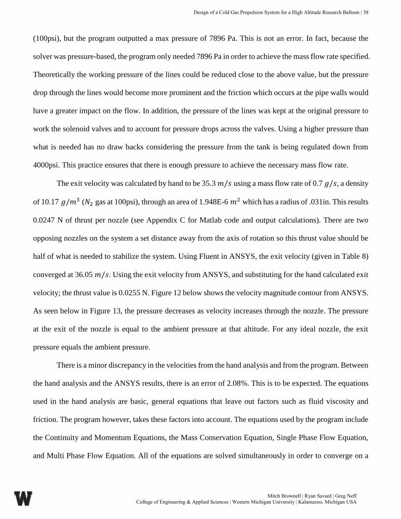
Mitch Brownell | Ryan Savard | Greg Neff College of Engineering & Applied Sciences | Western Michigan University | Kalamazoo, Michigan USA
(100psi), but the program outputted a max pressure of 7896 Pa. This is not an error. In fact, because the
solver was pressure-based, the program only needed 7896 Pa in order to achieve the mass flow rate specified.
Theoretically the working pressure of the lines could be reduced close to the above value, but the pressure
drop through the lines would become more prominent and the friction which occurs at the pipe walls would
have a greater impact on the flow. In addition, the pressure of the lines was kept at the original pressure to
work the solenoid valves and to account for pressure drops across the valves. Using a higher pressure than
what is needed has no draw backs considering the pressure from the tank is being regulated down from
4000psi. This practice ensures that there is enough pressure to achieve the necessary mass flow rate.
The exit velocity was calculated by hand to be 35.3 𝑚/𝑠 using a mass flow rate of 0.7 𝑔/𝑠, a density
of 10.17 𝑔/𝑚3 (𝑁2 gas at 100psi), through an area of 1.948E-6 𝑚2 which has a radius of .031in. This results
0.0247 N of thrust per nozzle (see Appendix C for Matlab code and output calculations). There are two
opposing nozzles on the system a set distance away from the axis of rotation so this thrust value should be
half of what is needed to stabilize the system. Using Fluent in ANSYS, the exit velocity (given in Table 8)
converged at 36.05 𝑚/𝑠. Using the exit velocity from ANSYS, and substituting for the hand calculated exit
velocity; the thrust value is 0.0255 N. Figure 12 below shows the velocity magnitude contour from ANSYS.
As seen below in Figure 13, the pressure decreases as velocity increases through the nozzle. The pressure
at the exit of the nozzle is equal to the ambient pressure at that altitude. For any ideal nozzle, the exit
pressure equals the ambient pressure.
There is a minor discrepancy in the velocities from the hand analysis and from the program. Between
the hand analysis and the ANSYS results, there is an error of 2.08%. This is to be expected. The equations
used in the hand analysis are basic, general equations that leave out factors such as fluid viscosity and
friction. The program however, takes these factors into account. The equations used by the program include
the Continuity and Momentum Equations, the Mass Conservation Equation, Single Phase Flow Equation,
and Multi Phase Flow Equation. All of the equations are solved simultaneously in order to converge on a

Design of a Cold Gas Propulsion System for a High Altitude Research Balloon | 39
Mitch Brownell | Ryan Savard | Greg Neff College of Engineering & Applied Sciences | Western Michigan University | Kalamazoo, Michigan USA
result⁵. Despite the inconsistencies between the two methods, the outlet velocities are different by only
0.65m/s or 2.08%.
Figure 12: Velocity Profile throughout Nozzle
Figure 13: Pressure Variation Throughout Nozzle

Design of a Cold Gas Propulsion System for a High Altitude Research Balloon | 40
Mitch Brownell | Ryan Savard | Greg Neff College of Engineering & Applied Sciences | Western Michigan University | Kalamazoo, Michigan USA
After the geometry was determined for the nozzle, a nozzle was modeled to be incorperated into the
system. The nozzle below in Figure 17, was given a hex head of half inch to fit any standard half inch
wrench. The tail end of the nozzle was threaded to 3/8-32 UNEF to comply with other standard thread
fittings. The nozzle has a mass of .0118 kg using stainless steel as the material. Four nozzles only contribute
to 2.08% percent of the total alloted weight.
Figure 14 – 3D Rendering of Nozzle Concept

Design of a Cold Gas Propulsion System for a High Altitude Research Balloon | 41
Mitch Brownell | Ryan Savard | Greg Neff College of Engineering & Applied Sciences | Western Michigan University | Kalamazoo, Michigan USA
FRAME DESIGN AND ANALYSIS
Overview
Many regulatory and design considerations were deliberated when constructing the various designs
to house this High Altitude Cold Gas Propulsion System. The considerations that were accounted for in the
design of the frame included Federal Aviation Administration (FAA) high altitude research balloon
regulatory requirements, material strength properties, integrated strength in design, research component
fixture points as well as simulated impact testing. In order to achieve an optimal frame design, two iterations
were generated to select the strongest, lightest, and most aerodynamic frame to support the high altitude
propulsion system.
Federal Aviation Administration Frame Design Requirements and Considerations
Requirements provided by the United States Federal Aviation Administration state a payload
attached to a high altitude research balloon must not exceed a total payload weight of twelve pounds, net
weight, not including the weight of the balloon and required rigging. Although the total weight requirement
of the payload is twelve pounds, the individual payload weight limit is six pounds or 2.6kg. Along with the
weight requirements the frame system combination must also conform to the weight per surface area
requirement which requires the payload to not exceed a weight of three ounces per square inch. Since the
payload can experience violent 60-250 miles per hour winds while passing through the jet stream, a light
weight aerodynamic frame was designed with minimal surface area allowing for turbulent winds to pass
through the frame providing stability and minimal wind disturbance.
Frame Iterations
Two iterations of frames were modeled and compared using SolidWorks design software and
ANSYS static simulation software. Various combinations of geometries and materials were selected to see
which configuration would best suit the specific needs and design requirements. The first frame design
consisted of circular hollow dowels that served as struts connecting the top circular ring to the bottom

Design of a Cold Gas Propulsion System for a High Altitude Research Balloon | 42
Mitch Brownell | Ryan Savard | Greg Neff College of Engineering & Applied Sciences | Western Michigan University | Kalamazoo, Michigan USA
circular ring. Top and bottom circular rings were designed using a rectangular cross section. Although this
cross section provided more surface area then the circular rings it was determined that this configuration
would allow for easier mounting of components. This configuration allowed for structural rigidity, as a well
as surfaces dimensions that would provide minimal surface area for wind to catch while passing through
the turbulent jet stream with minimal disruption. The second iteration of the frame provided struts that had
a rectangular cross section. Along with the rectangular profile of the struts the rings were maintained with
a rectangular cross-section. With this second variation it was determined that the additional flat surfaces
area of the rectangular cross section would allow for turbulent air to rotate the frame around its central
fixation point. Each of these Frame Iterations can be seen in the Appendix D.
Integrated Strength in Design
Certain design considerations were taken into account when designing a frame that could withstand
the extreme wind conditions and absorb ground impact while protecting any research devices that will be
affixed to the frame. When designing a frame to support a high altitude cold gas propulsion system,
considerations including component geometry and aerodynamics were accounted for. Using information
gathered from various strength of materials and mechanics of materials courses, geometries were selected
that would decrease surface areas, and provide minimal wind resistance. The design which was selected for
the final iteration of the frame included rings with rectangular cross sections which provided sufficient
surface areas to attach supporting struts and research components. By integrating the cylindrical struts into
the design of the frame structural rigidity and a streamline design features were achieved. The selected
frame design can be seen in Figure 15, on the following page.

Design of a Cold Gas Propulsion System for a High Altitude Research Balloon | 43
Mitch Brownell | Ryan Savard | Greg Neff College of Engineering & Applied Sciences | Western Michigan University | Kalamazoo, Michigan USA
Figure 15: Frame Assembly
Material Strength Properties
The most important aspect of the frame design was selecting a material that could provide superior
structural rigidity and strength. Although structural rigidity and strength were paramount to the design of
the frame, it was equally important to provide a frame that conformed to the weight requirement that was
provided by the FAA. This requirement stated that the total payload must not exceed twelve pounds, and
that weight must be divided into payloads weighing less than six pounds each. With all of these
considerations in mind, various materials were compared throughout the design selection process to insure
that optimal strength was achieved while maintaining the lowest possible weight. The materials that were
considered included, AL 6061-T6 Aluminum alloy, 17-7PH Stainless Steel, Ti-6AL-4V Titanium alloy,
and High Strength Carbon-Fiber-epoxy. These materials mechanical and physical properties can be found
on the following page in Table 9.

Design of a Cold Gas Propulsion System for a High Altitude Research Balloon | 44
Mitch Brownell | Ryan Savard | Greg Neff College of Engineering & Applied Sciences | Western Michigan University | Kalamazoo, Michigan USA
Material Selection
Material AL 6061-T6 Ti-6AL-4V 17-7 Stainless Steel High Modulus Carbon Fiber
Density(g/cc) 2.7 4.43 7.8 1.63
Rockwell Hardness 40 36 38 10.16
Ultimate Tensile Strength (MPa) 310 950 1240 1056
Tensile Strength Yield (Mpa) 276 880 1030 141.4
Elongation at Break (%) 17 14 3-7 N/A
Modulus of Elasticity (Gpa) 68.9 113.8 204 215
Modulus/ weight ratio 2.6 2.53 2.54 13.44
Mass of Frame (grams) 400 572.71 1818.4 380
Table 9 – Material property table with mass of frame properties included 11-15
Material Selection Criterion
As noted above four materials were compared and tested in the design of this frame. It can be
seen in Table 9 above, that all of the materials outlined have sufficient mechanical and physical properties
to conform to the design teams requirements for a high strength frame. Although all of the materials
conform to the desired strength requirements by way of providing high elastic modulus’s and ultimate
tensile strengths, they do not all conform to the low weight requirement presented by the design team and
FAA. Of the four materials presented above, only two of the materials provide both a high strength and
low weight properties. These materials include the AL 6061-T6 aluminum alloy, and the High Modulus
Carbon Fiber. After narrowing the materials down to two, it was determined that the optimum material
for this application was the High Modulus Carbon Fiber. The Carbon Fiber selected provided a very low
density of 1.63 grams per cubic centimeter and very high elastic modulus of 215 GPa. This material
allowed for the high strength to weight requirement to be satisfied. Although the material properties were
the primary deciding factor, the manufacturability of the parts was also taken into consideration. The
High Modulus Carbon Fiber selected provides a diverse ability to be produced into customized complex
shapes at a relatively low cost of manufacturing while removing the human element of error. After the
selecting a material based on the material properties, FEA testing was done to validate the selection of the
High Modulus Carbon Fiber against the other three materials this can be found in the following section.

Design of a Cold Gas Propulsion System for a High Altitude Research Balloon | 45
Mitch Brownell | Ryan Savard | Greg Neff College of Engineering & Applied Sciences | Western Michigan University | Kalamazoo, Michigan USA
FEA Frame Analysis
Frame FEA analysis was conducted using ANSYS Static Loading simulation software. The frame
which was selected to conform to the requirements outlined earlier in this section can be found in the
Appendix D. FEA testing was conducted on the selected frame with an applied material of High Modulus
Carbon Fiber which was determined from calculations and research to posses the ideal material properties
for the design requirements. This FEA analysis was run utilizing a 35 Newton static load applied to the
bottom of the frame while constraining the top of the frame to simulate an impact with the ground which
would be experienced after the research balloon pops and the system returns to earth via parachute. The
variability of the impact is based upon two parameters the weight of the system and the parachute size
which was approximated. Results that were gathered include the total deformation of the frame, and
maximum principal stress which can be found in Appendix D.
Material Selection Conclusion
After analyzing the various options in regards to material selection it was decided that high modulus
carbon fiber would be used in the fabrication of the frame. Many reasons weighed into the selection of high
modulus carbon fiber, but the following are key reasons as to why the material was selected. The versatility
of high strength carbon fiber allows for customizable design features, while maintaining a very high strength
to weight ratio that is not rivaled by any other current materials. Other details leading to the selection of
high strength carbon fiber are cost of production, ease of implementation, and its corrosion resistant
properties that are unmatched by most metals. The ease of implementation allows for the ordering of
specific parts utilizing the SolidWorks model files rather than ordering stock materials and having to
machine components in house risking human error. Subsequently carbon fiber is comprised primarily of a
carbon weave and an epoxy bonding agent. No corrosion would exist from the bonding of the carbon fiber
parts or environmental conditions. Over all the use of carbon fiber in this frame was essential to conform
to the stringent weight requirements that are presented by the FAA as well as the design teams desired
strength requirements that would allow for a stable and safe return of scientific data, and research devices.

Design of a Cold Gas Propulsion System for a High Altitude Research Balloon | 46
Mitch Brownell | Ryan Savard | Greg Neff College of Engineering & Applied Sciences | Western Michigan University | Kalamazoo, Michigan USA
OVERALL DESIGN ASSEMBLY OVERVIEW
The three main components of the cold gas propulsion system, the high-pressure cold gas reservoir,
the converging thrust nozzle, and the frame, were assembled in a three-dimensional solid modeling program
to ensure a geometric fit, as well as to ensure a proper and final design. Figure 16 below displays the final
overall design as modeled in SolidWorks three dimensional software.
Figure 16 –3D View of Overall Cold Gas Propulsion System

Design of a Cold Gas Propulsion System for a High Altitude Research Balloon | 47
Mitch Brownell | Ryan Savard | Greg Neff College of Engineering & Applied Sciences | Western Michigan University | Kalamazoo, Michigan USA
Figure 17 below is the piping and instrumentation diagram (P&ID) in which the designed system
was referenced to. The diagram below clearly outlines the tank, thrusters, pressure regulators in the system
as well as gas filters to ensure proper pressure regulation and laminar flow characteristics on the output of
the thruster nozzle. A relief valve will be installed on the final design of the cold gas propulsion system to
allow for emergency relief to purge the system in case of abrupt altitude declination, acute rise in
temperature that would cause the pressure in the reservoir to burst, etc. As will be outlined in the “Further
Recommendations” section, this P&ID diagram does not include the scope of the control system that would
be essential to remotely controlling the positioning of the balloon, using solenoids and other electronic
devices to control the gas flow.
Figure 17 – P&ID Diagram of Dual Thruster System3
The overall weight of the system, including piping, fasteners, nozzles, frame, tank, and other
components totaled to be 1.7926 kg. The goal of the design for the total propulsion system was to not exceed
2.26 kg without payload. The FAA regulates the maximum payload that a high altitude research balloon
carry is 2.72 kg. The design team originally allocated for 0.46 kg of payload to be used for the scientific
sensors/radiosondes/cameras/equipment that would also be on the flight along with the cold gas propulsion
system. As seen in Table 10, on the following page, 0.92 kg was the remaining mass allotted for scientific
equipment that would be attached to the unit. This would allow for 34% of the FAA regulated weight to be

Design of a Cold Gas Propulsion System for a High Altitude Research Balloon | 48
Mitch Brownell | Ryan Savard | Greg Neff College of Engineering & Applied Sciences | Western Michigan University | Kalamazoo, Michigan USA
‘leftover’ from the design. This mass could be used on the research rig elsewhere besides the cold gas
propulsion system. The lightweight design was a main goal throughout the design process, which included
FEA optimization of the tank and frame to included materials that would allow for high loads to be carried,
as well as be able to have the highest strength to weight ratio possible.
Although the final design from the design team did not include any complete design or in-depth
planning for the valves, regulators, filters, or emergency relief valves, the weight of those components were
factored into the overall design weight due to the importance of those components to the overall application
of the system applied to the research balloon population system. Table 10 below shows the mass breakdown
of the components within the system.
Component Mass Total Mass Percentage of FAA
Standard (2.72 kg)
Frame/Piping 0.293 kg 10.77%
Tank and Gas 0.6524 kg 23.98%
Nozzles 0.0472 kg 1.73%
Valves/Filters/Regulators 0.800 kg 29.41%
Total 1.7926 65.90%
Remainder for
Sensors/Cameras/Equipment
/GPS/Radiosonde
0.9274 34.1%
Table 10 – Overall Mass Property Summary

Design of a Cold Gas Propulsion System for a High Altitude Research Balloon | 49
Mitch Brownell | Ryan Savard | Greg Neff College of Engineering & Applied Sciences | Western Michigan University | Kalamazoo, Michigan USA
VALIDATION METHOLDOLOGY
For any design project, it is crucial to validate theoretical results with experimental results. The
payload unit as a whole, including the frame, gas storage tank, nozzles, and gas transmission system, was
simulated using computer software such as an FEA and a CFD. FEA was performed on the frame to ensure
that it could withstood its own weight, and the load caused by impact, applied to the base of the frame upon
its decent via parachute. The propellant tank was analyzed using FEA within Autodesk Inventor to validate
the designs developed by the design team. The CFD analysis was performed on the propulsion system to
confirm that the nozzles were producing an adequate amount of thrust. FEA was utilized to ensure that the
gas transmission systems, along with the nozzles, were able to withstand the high pressure within the system.
This validation was done alongside of the design of the frame, tank, and propulsions system. No
experimental results were gathered.

Design of a Cold Gas Propulsion System for a High Altitude Research Balloon | 50
Mitch Brownell | Ryan Savard | Greg Neff College of Engineering & Applied Sciences | Western Michigan University | Kalamazoo, Michigan USA
FURTHER RECOMMENDATIONS
The scope of the design project included designing, modeling, analyzing, and building a cold gas
propulsion system that will be able to be affixed to a high altitude research balloon. Due to the timeline of
the project, the design team was unable to carry the project into any prototyping stages such as in-depth
testing, validation, and building of a system.
A recommendation for future projects include designing a control system to provide, in real time,
the proper amount of propellant for each nozzle. Accelerometers and gyroscopes would be placed on the
perimeter of the frame to provide feedback in order to stabilize the system. Another recommendation for
the future of the cold gas propulsion system project is to design a test stand for thorough testing of the
system in a vacuum chamber, which would simulate high-altitude (low pressure) conditions. If the results
of the testing validate the simulated values calculated in this design project, the design team would further
recommend constructing the system outlined in this design report for research implementation.

Design of a Cold Gas Propulsion System for a High Altitude Research Balloon | 51
Mitch Brownell | Ryan Savard | Greg Neff College of Engineering & Applied Sciences | Western Michigan University | Kalamazoo, Michigan USA
CONCLUSION
Cold gas propulsion, as used in many applications today including aerospace/aeronautical research,
is a defining technology in high-altitude weather balloon stabilization today. This design project
encompassed cold gas technology and implements it into a system that can be applied to high altitude
research balloon. This system can provide an ability to consistently and accurately record atmospheric,
weather, and chemical conditions in the stratosphere. Through design, calculations, modeling, CFD
simulation and FEA analysis, the design team successfully modeled a cold gas propulsion system that will
operate within regulations dictated by the FAA, while providing a stable, and safe way to maneuver research
equipment attached to a stratospheric balloon. The target weight for the system was set at 2.26kg so 0.47
kg could be used for data acquisition equipment. The final weight was rendered, using material densities in
Solidworks mass simulator, to give an estimated overall system weight of 1.80 kg which leaves almost
0.8kg for data acquisition equipment. Although the design goal was achieved and exceeded based on
theoretical results, the construction of the high altitude cold gas system was not conducted due to lack of
time, and resources. This technical engineering design project successfully suggested a viable means of
high altitude stabilization and maneuverability.

Design of a Cold Gas Propulsion System for a High Altitude Research Balloon | 52
Mitch Brownell | Ryan Savard | Greg Neff College of Engineering & Applied Sciences | Western Michigan University | Kalamazoo, Michigan USA
REFERENCES
[1] Bzibziak, R. (1992). Miniature cold gas thrusters. AIAA paper, (92-325).
[2] Cardin, J., & Acosta, J. (2000). Design and test of an economical cold gas propulsion system.
[3] High Altitude Wind Speed, Direction and Air Temperature at Black Rock, Nevada for Amature
Rocketry Application, Ken Biba, AeroPac Inc., Santa Rosa, California, 95404.
[4] U.S Standard Atmosphere Air Properties in SI Units http://www.engineeringtoolbox.com/standard-
atmosphere-d_604.html
[5] ANSYS FLUENT Theory Guide, Ansys Inc., October 2012.
[6] Hashem, A. A. Design and Testing of a Cold Gas System. Proceedings of the 4th International
Spacecraft Propulsion Conference (ESA SP-555). 2004. 86.1-86.7
[7] Köhler, J., Bejhed, J., Kratz, H., Bruhn, F., Lindberg, U., Hjort, K., & Stenmark, L. (2002). A hybrid
cold gas microthruster system for spacecraft. Sensors and Actuators A: Physical, 97, 587-598
[8] Lugini, C., & Romano, M. (2009). A ballistic-pendulum test stand to characterize small cold-gas
thruster nozzles. Acta Astronautica, 64(5), 615-625.
[9] Micci, M. M., & Ketsdever, A. D. (Eds.). (2000). Micropropulsion for small spacecraft (Vol. 187).
AIAA.
[10] Nitrogen Material Safety Data Sheet (MSDS) Documentation. Airgas. http://www.airgas.co
m/documents/pdf/001040.pdf
[11] American Metals Company (2002). 17-7 Stainless Steel Technical Data Sheet.
Retrieved February 2, 2014, from https://www.metalshims.com/t-17-7-Stainless-Steel-technical-
data-sheet.aspx
[12] Hegde, R. R., Dahiya, A., & Kamath, M. G. (2004, April). CARBON FIBERS. Retrieved March 6,
2014, from http://www.engr.utk.edu/mse/Textiles/CARBON%20FIBERS.htm
Design of a Cold Gas Propulsion System for a High Altitude Research Balloon | 53
Mitch Brownell | Ryan Savard | Greg Neff College of Engineering & Applied Sciences | Western Michigan University | Kalamazoo, Michigan USA
[13] High Performance Composites (2009, January). The making of carbon fiber: Composites World.
Retrieved March 6, 2014, from http://www.compositesworld.com/articles/the-making-of-carbon-
fiber
[14] Key to Metals (2006, March). Chemical and Mechanical Properties of Titanium and Its Alloys:
KEY to METALS Articles. Retrieved March 6, 2014, from
http://www.keytometals.com/Article126.htm
[15] Key to Metals (2006, March). Properties of Aluminum and Aluminum Alloys: Total Material
Article. Retrieved March 5, 2014, from
http://www.keytometals.com/page.aspx?ID=CheckArticle&site=ktn&NM=142

Design of a Cold Gas Propulsion System for a High Altitude Research Balloon | 54
Mitch Brownell | Ryan Savard | Greg Neff College of Engineering & Applied Sciences | Western Michigan University | Kalamazoo, Michigan USA
APPENDICES
APPENDIX A – CONCEPT & SCHEDULDE MATRICES
APPENDIX B – TANK ANALYSIS MSDS/FEA RESULTS
APPENDIX C – NOZZLE DESIGN & ANALYSIS CODE/FIGURES
APPENDIX D – FRAME DESIGN ANALYSIS FIGURES
APPENDIX E – MECHANICAL & AEROSPACE PROGRAM OUTCOMES
APPENDIX F - RESUMES

Design of a Cold Gas Propulsion System for a High Altitude Research Balloon | 55
Mitch Brownell | Ryan Savard | Greg Neff College of Engineering & Applied Sciences | Western Michigan University | Kalamazoo, Michigan USA
Conc
ept R
efere
nce
Num
ber
1.a
2.a
3.a4.a
Gas/
Prop
ellan
tNi
troge
nNi
troge
nNi
troge
nCa
rbon
Diox
ide
Thru
ster
Mat
erial
Titan
ium41
0 St
ainles
s St
eel
410/
NACE
Sta
inles
s St
eel
410/
NACE
Sta
inles
s St
eel
Othe
r Des
ign N
otes
Conv
ergin
g
Cust
om P
rope
llant
Tan
k
Subs
onic,
Conv
ergin
g/Di
verg
ing
Cust
om P
rope
llant
Tan
k
Conv
ergin
g
Mod
ular P
rope
llant
Tan
k
High
Pre
ssur
e Co
nver
ging
Cust
om T
ank
OVE
RALL
DES
IGN
RATI
NG82
.91
66.0
573
.00
67.5
4
Geom
etric
/Des
ign R
ating
85.0
665
.08
70.5
261
.52
Cost
/Qua
lity R
ating
79.6
867
.51
76.7
376
.58
Impo
rtanc
e Fa
ctor
73.6
74.5
77.3
83.6
1.1
48.
010
.09.
09.
0
1.2
77.
06.
07.
08.
0
83.2
68.8
58.4
70.4
2.1
98.
04.
010
.08.
0
2.2
88.
08.
04.
04.
0
2.3
89.
09.
03.
09.
0
85.7
60.5
76.2
69.5
3.1
69.
06.
07.
08.
0
3.2
87.
07.
06.
07.
0
3.3
710
.05.
010
.06.
0
93.0
74.3
90.0
45.2
4.1
710
.05.
09.
08.
0
4.2
88.
09.
010
.05.
0
4.3
810
.08.
08.
01.
0
78.9
52.1
63.2
68.9
5.1
610
.08.
07.
08.
0
5.2
76.
03.
06.
05.
0
5.3
68.
05.
06.
08.
0
Ratin
g Su
mm
ary
Conc
ept S
elec
tion
Eval
uatio
n
Desig
n fo
r Col
d Ga
s Pro
pulsi
on S
yste
m
Wes
tern
Mich
igan
Unive
rsity
Colle
ge o
f Eng
ineer
ing &
App
lied
Scien
ces
Mitc
h Br
owne
ll
Greg
Nef
f
Ryan
Sav
ard
Ref N
o.
Moun
tabi
lity o
n ap
plica
tion
Desig
n Co
ncep
ts
Optim
izatio
n of
gas
flow
Over
all T
hrus
t Val
ue
Desc
riptio
n of
Des
ign P
aram
eter
Desi
gn P
aram
eter
s/Co
ndito
ns
Abilit
y for
CAD
/ANS
YS m
odel
ing
Maxim
izatio
n of
lam
inar
flow
Size
app
licab
le to
cube
sat
Mach
inib
ility r
elat
ive to
size
Head
Los
s
Gas
Del
iver
y Sys
tem
Tank
Des
ign/
Mate
rials
/Ana
lysis
Gas
Deliv
ery S
yste
m a
nd M
ass
Flow
Mate
rial P
rope
rties
Desi
gn C
onsi
dera
tions
3 4 5
Idea
l gas
pro
perti
es fo
r app
licat
ion
Geo
met
ric C
hara
cter
istic
s
Man
ufac
tura
bilit
y/Pro
duca
bilit
y
Ease
of m
ater
ial a
cces
s
Part
Com
plex
ity
Thru
st M
axim
izat
ion
1 2
APPENDIX A – CONCEPT & SCHEDULDE MATRICES
Table 11 – Concept Selection Matrix

Design of a Cold Gas Propulsion System for a High Altitude Research Balloon | 56
Mitch Brownell | Ryan Savard | Greg Neff College of Engineering & Applied Sciences | Western Michigan University | Kalamazoo, Michigan USA
Per
iod
Hig
hlig
ht:1
Plan
Act
ual
% C
ompl
ete
Act
ual (
beyo
nd p
lan)
% C
ompl
ete
(bey
ond
plan
)
Sep
Oct
Nov
Dec
Jan
Feb
Mar
Apr
PL
AN
PL
AN
AC
TU
AL
AC
TU
AL
PER
CEN
T
AC
TIV
ITY
ST
AR
TD
UR
AT
ION
ST
AR
TD
UR
AT
ION
CO
MP
LET
EP
ERIO
DS
12
34
56
78
910
1112
1314
1516
1718
1920
2122
2324
2526
2728
2930
3132
Secu
re F
undi
ng4
52
810
0%
App
ly to
OV
PR4
44
510
0%
Ope
n Ta
b w
ith M
E of
fice
91
102
100%
Pro
posa
l10
210
00%
Des
ign
(CA
D)
93
90
20%
Con
verg
ing
Noz
zle
93
90
15%
Stor
age
Tank
93
90
0%
Gas
Tra
nsm
issi
on S
yste
m9
39
05%
Har
dwar
e4
84
00%
Res
earc
h C
ompo
nent
s4
84
025
%
Dev
elop
Pri
ce S
heet
48
40
25%
Ord
er h
arda
re15
115
00%
Mak
e no
zzle
172
00
0%
Bui
ld P
ropu
lsio
n Sy
stem
183
180
0%
Con
stru
ct S
yste
m18
418
010
%
Pro
puls
ion
Syst
em T
est
195
190
0%
Dat
a A
naly
sis
202
200
0%
Rep
ort
254
250
0%
Col
d G
as P
ropu
lsio
n Sy
stem
Figure 18 – Design Process Gantt Chart

Design of a Cold Gas Propulsion System for a High Altitude Research Balloon | 57
Mitch Brownell | Ryan Savard | Greg Neff College of Engineering & Applied Sciences | Western Michigan University | Kalamazoo, Michigan USA
APPENDIX B – TANK ANALYSIS MSDS/FEA RESULTS
Material Safety Data Sheet 10
1. CHEMICAL PRODUCT AND COMPANY IDENTIFICATION
MATHESON TRI-GAS, INC. EMERGENCY CONTACT:
959 ROUTE 46 EAST CHEMTREC 1-800-424-9300 PARSIPPANY, NEW JERSEY 07054-0624
INFORMATION CONTACT:
973-257-1100
SUBSTANCE: NITROGEN, COMPRESSED GAS
TRADE NAMES/SYNONYMS:
MTG MSDS 67; DIATOMIC NITROGEN; DINITROGEN; NITROGEN; NITROGEN-14; NITROGEN
GAS; UN 1066; N2; MAT16625; RTECS QW900000
CHEMICAL FAMILY: inorganic, gas
CREATION DATE: Jan 24 1989
REVISION DATE: Jun 16 2005
2. COMPOSITION, INFORMATION ON INGREDIENTS
COMPONENT: NITROGEN, COMPRESSED GAS
CAS NUMBER: 7727-37-9
PERCENTAGE: 100
3. HAZARDS IDENTIFICATION
NFPA RATINGS (SCALE 0-4): HEALTH=1 FIRE=0 REACTIVITY=0
EMERGENCY OVERVIEW:
COLOR: colorless
PHYSICAL FORM: gas
ODOR: odorless
MAJOR HEALTH HAZARDS: difficulty breathing

Design of a Cold Gas Propulsion System for a High Altitude Research Balloon | 58
Mitch Brownell | Ryan Savard | Greg Neff College of Engineering & Applied Sciences | Western Michigan University | Kalamazoo, Michigan USA
PHYSICAL HAZARDS: Containers may rupture or explode if exposed to heat.
POTENTIAL HEALTH EFFECTS: INHALATION:
SHORT TERM EXPOSURE: nausea, vomiting, difficulty breathing, headache, drowsiness, dizziness,
tingling sensation, loss of coordination, convulsions, coma
LONG TERM EXPOSURE: no information is available
SKIN CONTACT:
SHORT TERM EXPOSURE: no information on significant adverse effects LONG TERM EXPOSURE:
no information on significant adverse effects EYE CONTACT:
SHORT TERM EXPOSURE: irritation
LONG TERM EXPOSURE: no information on significant adverse effects
INGESTION:
SHORT TERM EXPOSURE: ingestion of a gas is unlikely
LONG TERM EXPOSURE: ingestion of a gas is unlikely
4. FIRST AID MEASURES
INHALATION: If adverse effects occur, remove to uncontaminated area. Give artificial respiration if not
breathing. If breathing is difficult, oxygen should be administered by qualified personnel. Get immediate
medical attention.
SKIN CONTACT: Wash exposed skin with soap and water.
EYE CONTACT: Flush eyes with plenty of water.
INGESTION: If a large amount is swallowed, get medical attention.
NOTE TO PHYSICIAN: For inhalation, consider oxygen
5. FIRE FIGHTING MEASURES
FIRE AND EXPLOSION HAZARDS: Negligible fire hazard. Pressurized containers may rupture or
explode if exposed to sufficient heat.

Design of a Cold Gas Propulsion System for a High Altitude Research Balloon | 59
Mitch Brownell | Ryan Savard | Greg Neff College of Engineering & Applied Sciences | Western Michigan University | Kalamazoo, Michigan USA
EXTINGUISHING MEDIA: carbon dioxide, regular dry chemical Large fires: Use regular foam or flood
with fine water spray.
FIRE FIGHTING: Move container from fire area if it can be done without risk. Cool containers with
water spray until well after the fire is out. Stay away from the ends of tanks. Withdraw immediately in
case of rising sound from venting safety device or any discoloration of tanks due to fire. For tank, rail car
or tank truck, evacuation radius: 800 meters (1/2 mile). Use extinguishing agents appropriate for
surrounding fire. Cool containers with water spray until well after the fire is out. Apply water from a
protected location or from a safe distance. Do not get water directly on material. Reduce vapors with
water spray. Avoid inhalation of material or combustion by-products. Stay upwind and keep out of low
areas. Consider downwind evacuation if material is leaking.
6. ACCIDENTAL RELEASE MEASURES
OCCUPATIONAL RELEASE:
Stop leak if possible without personal risk. Keep unnecessary people away, isolate hazard area and deny
entry. Stay upwind and keep out of low areas.
7. HANDLING AND STORAGE
STORAGE: Store and handle in accordance with all current regulations and standards. Subject to storage
regulations: U.S. OSHA 29 CFR 1910.101. Keep separated from incompatible substances.
8. EXPOSURE CONTROLS, PERSONAL PROTECTION
EXPOSURE LIMITS: NITROGEN, COMPRESSED GAS: NITROGEN:
ACGIH (simple asphyxiant)
VENTILATION: Provide local exhaust ventilation system. Ensure compliance with applicable exposure
limits.
EYE PROTECTION: Eye protection not required, but recommended.
CLOTHING: Protective clothing is not required.
GLOVES: Protective gloves are not required.
Design of a Cold Gas Propulsion System for a High Altitude Research Balloon | 60
Mitch Brownell | Ryan Savard | Greg Neff College of Engineering & Applied Sciences | Western Michigan University | Kalamazoo, Michigan USA
RESPIRATOR: Under conditions of frequent use or heavy exposure, respiratory protection may be
needed. Respiratory protection is ranked in order from minimum to maximum. Consider warning
properties before use. For Unknown Concentrations or Immediately Dangerous to Life or Health -
Any supplied-air respirator with full facepiece and operated in a pressure-demand or other positive-
pressure mode in combination with a separate escape supply.
Any self-contained breathing apparatus with a full facepiece
9. PHYSICAL AND CHEMICAL PROPERTIES
PHYSICAL STATE: gas
COLOR: colorless ODOR: odorless TASTE: tasteless
MOLECULAR WEIGHT: 28.0134
MOLECULAR FORMULA: N2
BOILING POINT: -321 F (-196 C)
FREEZING POINT: -346 F (-210 C) VAPOR PRESSURE: 760 mmHg @ -196 C VAPOR DENSITY
(air=1): 0.967
SPECIFIC GRAVITY: Not applicable
DENSITY: 1.2506 g/L
WATER SOLUBILITY: 1.6% @ 20 C
PH: Not applicable
VOLATILITY: 100%
ODOR THRESHOLD: Not available EVAPORATION RATE: Not applicable VISCOSITY: 0.01787 cP
@ 27 C
COEFFICIENT OF WATER/OIL DISTRIBUTION: Not applicable
SOLVENT SOLUBILITY:
Soluble: liquid ammonia
Slightly Soluble: alcohol

Design of a Cold Gas Propulsion System for a High Altitude Research Balloon | 61
Mitch Brownell | Ryan Savard | Greg Neff College of Engineering & Applied Sciences | Western Michigan University | Kalamazoo, Michigan USA
10. STABILITY AND REACTIVITY
REACTIVITY: Stable at normal temperatures and pressure.
CONDITIONS TO AVOID: Protect from physical damage and heat. Containers may rupture or explode if
exposed to heat.
INCOMPATIBILITIES: metals, oxidizing materials
HAZARDOUS DECOMPOSITION:
Thermal decomposition products: oxides of nitrogen
POLYMERIZATION: Will not polymerize.
11. TOXICOLOGICAL INFORMATION
Not available
12. ECOLOGICAL INFORMATION
Not available
13. DISPOSAL CONSIDERATIONS
Dispose in accordance with all applicable regulations.
14. TRANSPORT INFORMATION
U.S. DOT 49 CFR 172.101:
PROPER SHIPPING NAME: Nitrogen, compressed
ID NUMBER: UN1066
HAZARD CLASS OR DIVISION: 2.2
LABELING REQUIREMENTS: 2.2
CANADIAN TRANSPORTATION OF DANGEROUS GOODS:
SHIPPING NAME: Nitrogen, compressed
UN NUMBER: UN1066
CLASS: 2.2
15. REGULATORY INFORMATION

Design of a Cold Gas Propulsion System for a High Altitude Research Balloon | 62
Mitch Brownell | Ryan Savard | Greg Neff College of Engineering & Applied Sciences | Western Michigan University | Kalamazoo, Michigan USA
U.S. REGULATIONS:
CERCLA SECTIONS 102a/103 HAZARDOUS SUBSTANCES (40 CFR 302.4): Not regulated.
SARA TITLE III SECTION 302 EXTREMELY HAZARDOUS SUBSTANCES (40 CFR 355.30): Not
regulated.
SARA TITLE III SECTION 304 EXTREMELY HAZARDOUS SUBSTANCES (40 CFR 355.40): Not
regulated.
SARA TITLE III SARA SECTIONS 311/312 HAZARDOUS CATEGORIES (40 CFR 370.21):
ACUTE: Yes CHRONIC: No FIRE: No REACTIVE: No
SUDDEN RELEASE: Yes
SARA TITLE III SECTION 313 (40 CFR 372.65): Not regulated.
OSHA PROCESS SAFETY (29CFR1910.119): Not regulated.
STATE REGULATIONS:
California Proposition 65: Not regulated.
CANADIAN REGULATIONS: WHMIS CLASSIFICATION: A.
NATIONAL INVENTORY STATUS:
U.S. INVENTORY (TSCA): Listed on inventory
TSCA 12(b) EXPORT NOTIFICATION: Not listed.
CANADA INVENTORY (DSL/NDSL): Listed on inventory.
16. OTHER INFORMATION
MSDS SUMMARY OF CHANGES

Design of a Cold Gas Propulsion System for a High Altitude Research Balloon | 63
Mitch Brownell | Ryan Savard | Greg Neff College of Engineering & Applied Sciences | Western Michigan University | Kalamazoo, Michigan USA
Complete FEA Results (Tank Analysis)
Physical
Material Carbon Fiber
Density 1.77151 g/cm^3
Mass 0.122013 kg
Area 0.108354 m^2
Volume 0.000068875 m^3
Center of Gravity x=0.0706366 m
y=0.0000000000000410015 m
z=0 m Table 12 – Physical Properties of Carbon Fiber Tank
Simulation Results
Design Objective Single Point
Simulation Type Static Analysis
Last Modification Date 3/3/2014, 4:32 PM
Detect and Eliminate Rigid Body Modes No
Table 13 – Summary of FEA of Tank
Avg. Element Size (fraction of model diameter) 0.1
Min. Element Size (fraction of avg. size) 0.2
Grading Factor 1.5
Max. Turn Angle 60 deg
Create Curved Mesh Elements Yes
Table 14 – FEA Tank Details
Name Carbon Fiber
General Mass Density 1.77151 g/cm^3
Yield Strength 3375.41 MPa
Ultimate Tensile Strength 4147.78 MPa
Stress Young's Modulus 275.6 GPa
Poisson's Ratio 0.1 ul
Shear Modulus 125.273 GPa
Part Name(s) Tank Design 2.ipt
Table 15 – Material Property Summary
Reaction Force and Moment On Constraints
Constraint Name Reaction Force Reaction Moment
Magnitude Component (X,Y,Z) Magnitude Component (X,Y,Z)
Fixed Constraint:1 13348.1 N 13348.1 N 0 N m 0 N m
0 N 0 N m
0 N 0 N m
Table 16 – Resultant Forces & Moments

Design of a Cold Gas Propulsion System for a High Altitude Research Balloon | 64
Mitch Brownell | Ryan Savard | Greg Neff College of Engineering & Applied Sciences | Western Michigan University | Kalamazoo, Michigan USA
Result Summary
Name Minimum Maximum
Volume 68875 mm^3
Mass 0.122013 kg
Von Mises Stress 34.6488 MPa 1477.23 MPa
1st Principal Stress -31.0323 MPa 1527.5 MPa
3rd Principal Stress -460.342 MPa 148.896 MPa
Displacement 0 mm 0.286294 mm
Safety Factor 2.44589 ul 15 ul
Stress XX -154.623 MPa 1013.17 MPa
Stress XY -758.376 MPa 295.244 MPa
Stress XZ -297.014 MPa 289.754 MPa
Stress YY -94.1332 MPa 1131.14 MPa
Stress YZ -582.549 MPa 583.218 MPa
Stress ZZ -289.746 MPa 1136.63 MPa
X Displacement -0.286233 mm 0.010836 mm
Y Displacement -0.201867 mm 0.198078 mm
Z Displacement -0.200047 mm 0.198466 mm
Equivalent Strain 0.000103584 ul 0.00494942 ul
1st Principal Strain -0.00000246568 ul 0.00529917 ul
3rd Principal Strain -0.00203948 ul 0.000273855 ul
Strain XX -0.000897798 ul 0.00324633 ul
Strain XY -0.0030269 ul 0.0011784 ul
Strain XZ -0.00118547 ul 0.00115649 ul
Strain YY -0.00072349 ul 0.00393116 ul
Strain YZ -0.00232512 ul 0.00232779 ul
Strain ZZ -0.00135858 ul 0.00395335 ul
Table 17 – Summary of Stress/Strain Results

Design of a Cold Gas Propulsion System for a High Altitude Research Balloon | 65
Mitch Brownell | Ryan Savard | Greg Neff College of Engineering & Applied Sciences | Western Michigan University | Kalamazoo, Michigan USA
Figure 19 – Von Mises Stresses
Figure 20 – 1st Principal Stresses

Design of a Cold Gas Propulsion System for a High Altitude Research Balloon | 66
Mitch Brownell | Ryan Savard | Greg Neff College of Engineering & Applied Sciences | Western Michigan University | Kalamazoo, Michigan USA
Figure 21 – Total Displacement
Figure 22 – 3rd Principal Stresses
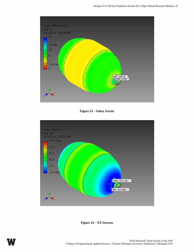
Design of a Cold Gas Propulsion System for a High Altitude Research Balloon | 67
Mitch Brownell | Ryan Savard | Greg Neff College of Engineering & Applied Sciences | Western Michigan University | Kalamazoo, Michigan USA
Figure 23 – Safety Factor
Figure 24 – XX Stresses

Design of a Cold Gas Propulsion System for a High Altitude Research Balloon | 68
Mitch Brownell | Ryan Savard | Greg Neff College of Engineering & Applied Sciences | Western Michigan University | Kalamazoo, Michigan USA
Figure 25 – YY Stresses
Figure 26 – YZ Stresses

Design of a Cold Gas Propulsion System for a High Altitude Research Balloon | 69
Mitch Brownell | Ryan Savard | Greg Neff College of Engineering & Applied Sciences | Western Michigan University | Kalamazoo, Michigan USA
Figure 27 – ZZ Stress
Figure 28 – XY Stresses

Design of a Cold Gas Propulsion System for a High Altitude Research Balloon | 70
Mitch Brownell | Ryan Savard | Greg Neff College of Engineering & Applied Sciences | Western Michigan University | Kalamazoo, Michigan USA
Figure 29 – Z Displacement
Figure 30 – Y Displacement

Design of a Cold Gas Propulsion System for a High Altitude Research Balloon | 71
Mitch Brownell | Ryan Savard | Greg Neff College of Engineering & Applied Sciences | Western Michigan University | Kalamazoo, Michigan USA
Figure 31 – 1st Principal Strain
Figure 32 – Equivalent Strain

Design of a Cold Gas Propulsion System for a High Altitude Research Balloon | 72
Mitch Brownell | Ryan Savard | Greg Neff College of Engineering & Applied Sciences | Western Michigan University | Kalamazoo, Michigan USA
Figure 33 – XX Strain
Figure 34 – 3rd Principal Strain

Design of a Cold Gas Propulsion System for a High Altitude Research Balloon | 73
Mitch Brownell | Ryan Savard | Greg Neff College of Engineering & Applied Sciences | Western Michigan University | Kalamazoo, Michigan USA
Figure 35 – YY Strain
Figure 36 – XZ Strain

Design of a Cold Gas Propulsion System for a High Altitude Research Balloon | 74
Mitch Brownell | Ryan Savard | Greg Neff College of Engineering & Applied Sciences | Western Michigan University | Kalamazoo, Michigan USA
Figure 37 – ZZ Strain
Figure 38 – YZ Strain

Design of a Cold Gas Propulsion System for a High Altitude Research Balloon | 75
Mitch Brownell | Ryan Savard | Greg Neff College of Engineering & Applied Sciences | Western Michigan University | Kalamazoo, Michigan USA
Figure 39 – XY Strain
Figure 40 – XZ Strain

Design of a Cold Gas Propulsion System for a High Altitude Research Balloon | 76
Mitch Brownell | Ryan Savard | Greg Neff College of Engineering & Applied Sciences | Western Michigan University | Kalamazoo, Michigan USA
APPENDIX C – NOZZLE DESIGN & ANALYSIS CODE/FIGURES
Matlab Code: clear,clc syms Cp r_inlet r_outlet Te eta NPR gamma Pe Pi Ti Ve_pipe T Force WindSpeed syms AirDensity SurfaceArea AirFlowRate c k R AreaRatio Mi Me Vi Ve %All calcualations are done at 100,000ft with a temperature of 231K at %that altitude. The working fluid is Nitrogen. Working pressure is 100psi. %ASSUMPTIONS: incompressible flow, isentropic, 95 isentropic efficiency, %adiabatic, constant temperature.
%% %Cp - Specific Heat (kJ/kgK) %Te - total temperature at the exit (K) %Pi - Pressure at the inlet of nozzle (Pa) %Pe - Pressure at the exit of the nozzle (Pa) (ambient pressure) %gamma - specifif heat ratio %rho = density of N2 at 100psi and 231K (kg/m^3)
k = 1.4; R = .2968; T = 231; rho = 10.17; Cp = 1.0039; Pi = 689475.73; Pe = 1185; Te = 231; gamma = 1.4;
%% %The thrust (T) in Newtons (kg*m/s^2) was calculated from a theoretical senario that
takes into %account the wind speed and air density at that altitude
WindSpeed = 16.764; %50ft/s into m/s AirDensity = .015; %kg/m^2 SurfaceArea = .0112903; %1ft^2 to m^2
AirFlowRate = AirDensity*WindSpeed*SurfaceArea; Force = AirFlowRate*WindSpeed; display(Force,'Force to achieve in Newtons'); %% %Setting the geometry for the nozzle inlet and outlet
% 1 in = .0254 meters
D_inlet=.25; %inches D_outlet=.062; %inches
r_inlet = (D_inlet/2)*.0254; r_outlet = (D_outlet/2)*.0254;
Ai = pi*r_inlet^2; Ae = pi*r_outlet^2;
display(Ai,'Area of inlet in meters^2'); display(Ae,'Area of outlet in meters^2');

Design of a Cold Gas Propulsion System for a High Altitude Research Balloon | 77
Mitch Brownell | Ryan Savard | Greg Neff College of Engineering & Applied Sciences | Western Michigan University | Kalamazoo, Michigan USA
ActualAreaRatio=Ai/Ae; display(ActualAreaRatio,'The actual area ratio'); %% %Mdot = Force/Ve_pipe Mdot = .0007; display(Mdot,'mass flow rate kg/s') %% Mdot_max = Ae*Pi*(2/(k+1))^((k+1)/(2*(k+1)))*sqrt((k/(R*T))); display(Mdot_max,'Maximum mass flow rate though the nozzle') %% Vi= Mdot/(rho*Ai); Ve= Mdot/(rho*Ae); display(Vi,'Inlet Velocity of Nozzle') display(Ve,'Exit Velocity of Nozzle')
%% c = sqrt(k*R*T*1000); Mach_inlet = Vi/c Mach_outlet =Ve/c %% AreaRatio = 1/((Vi/Ve)*sqrt(((1+(((k-1)/2)*(Ve/c)^2))/((1+((k-
1)/2)*(Vi/c)^2)))^((k+1)/(k-1)))); display(AreaRatio,'Ideal Nozzle Area Ratio'); %% Thrust=Mdot*Ve; display(Thrust,'Thrust in Newtons')
Matlab Output:
Force to achieve in Newtons =
0.0476
Area of inlet in meters^2 =
3.1669e-05
Area of outlet in meters^2 =
1.9478e-06
The actual area ratio =
16.2591
mass flow rate kg/s =
7.0000e-04
Maximum mass flow rate though the nozzle =
0.1752
Inlet Velocity of Nozzle =
2.1734
Exit Velocity of Nozzle =
35.3375

Design of a Cold Gas Propulsion System for a High Altitude Research Balloon | 78
Mitch Brownell | Ryan Savard | Greg Neff College of Engineering & Applied Sciences | Western Michigan University | Kalamazoo, Michigan USA
Mach_inlet =
0.0070
Mach_outlet =
0.1141
Ideal Nozzle Area Ratio =
16.1333
Thrust in Newtons =
0.0247
>>
Figure 41 – Shear Stress Model of Nozzle

Design of a Cold Gas Propulsion System for a High Altitude Research Balloon | 79
Mitch Brownell | Ryan Savard | Greg Neff College of Engineering & Applied Sciences | Western Michigan University | Kalamazoo, Michigan USA
Figure 42 – 3D Layout of Friction Coefficient in Nozzle

Design of a Cold Gas Propulsion System for a High Altitude Research Balloon | 80
Mitch Brownell | Ryan Savard | Greg Neff College of Engineering & Applied Sciences | Western Michigan University | Kalamazoo, Michigan USA
APPENDIX D – FRAME DESIGN ANALYSIS FIGURES
Figure 43- Total FEA Frame Displacement (with 20N load applied to base)
Figure 44 – Deformation of Frame Struts (with 20N load applied to base)
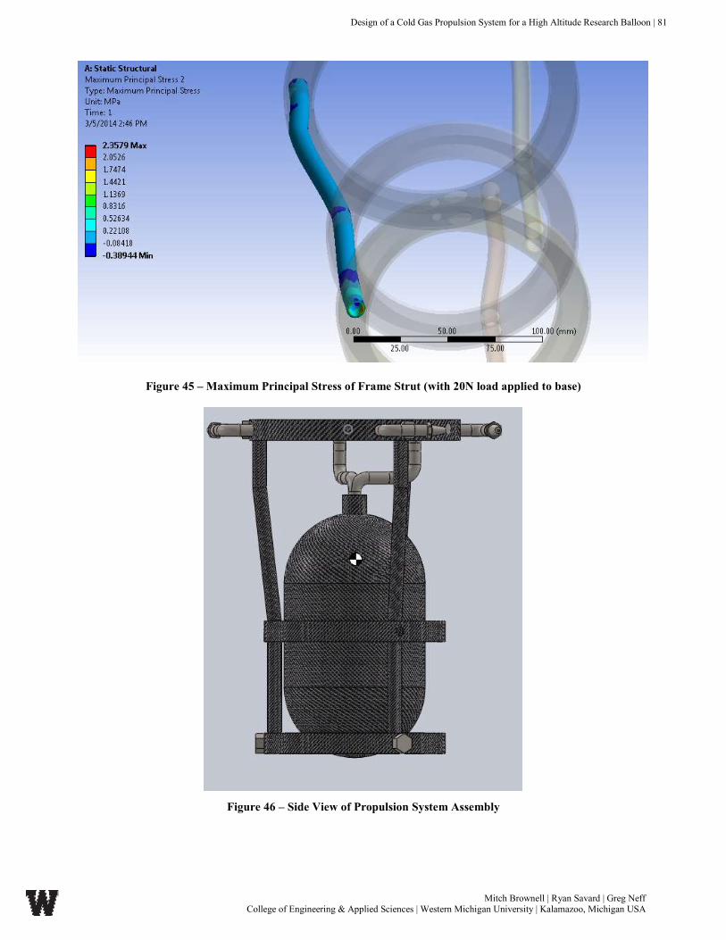
Design of a Cold Gas Propulsion System for a High Altitude Research Balloon | 81
Mitch Brownell | Ryan Savard | Greg Neff College of Engineering & Applied Sciences | Western Michigan University | Kalamazoo, Michigan USA
Figure 45 – Maximum Principal Stress of Frame Strut (with 20N load applied to base)
Figure 46 – Side View of Propulsion System Assembly
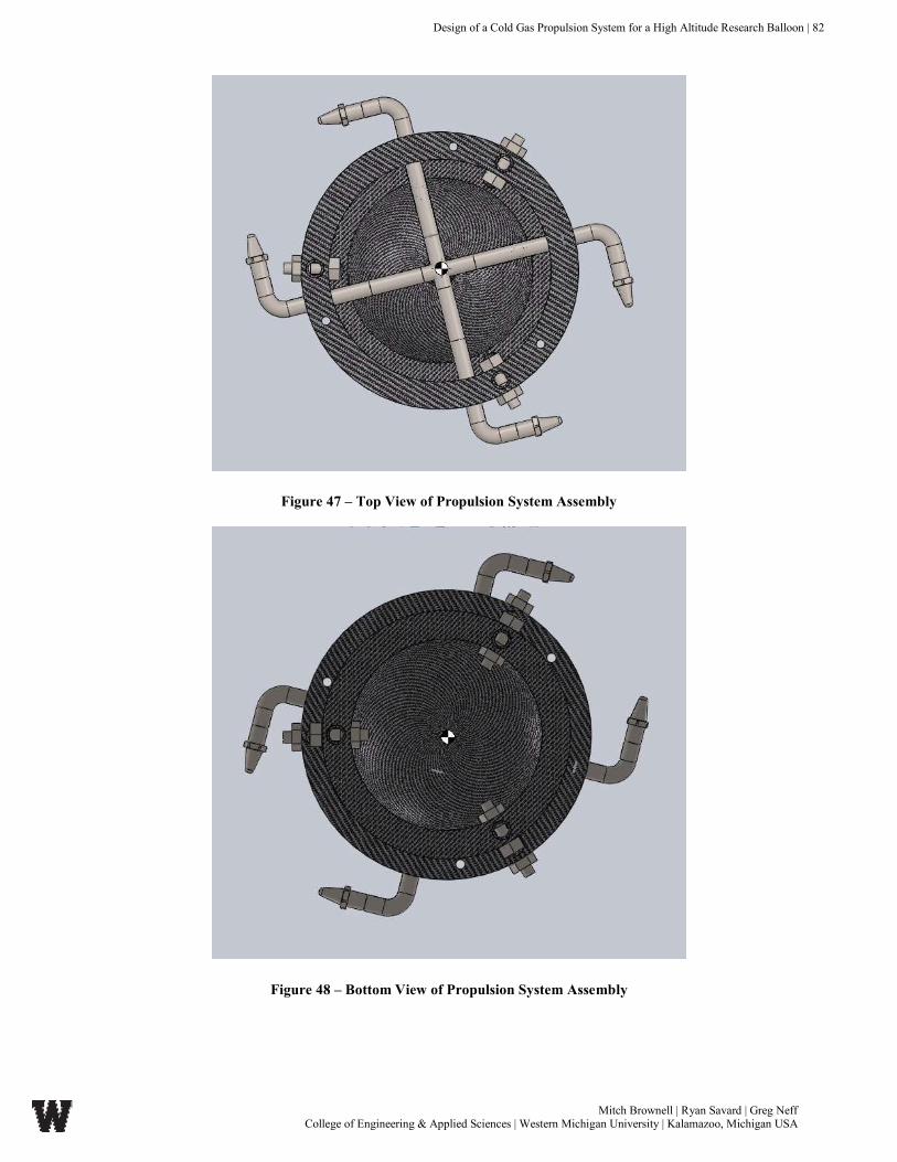
Design of a Cold Gas Propulsion System for a High Altitude Research Balloon | 82
Mitch Brownell | Ryan Savard | Greg Neff College of Engineering & Applied Sciences | Western Michigan University | Kalamazoo, Michigan USA
Figure 47 – Top View of Propulsion System Assembly
Figure 48 – Bottom View of Propulsion System Assembly

Design of a Cold Gas Propulsion System for a High Altitude Research Balloon | 83
Mitch Brownell | Ryan Savard | Greg Neff College of Engineering & Applied Sciences | Western Michigan University | Kalamazoo, Michigan USA
APPENDIX E – MECHANICAL & AEROSPACE PROGRAM OUTCOMES
Assessment of Western Michigan University College of Engineering & Applied Sciences
Department of Mechanical & Aerospace Engineering Academic Program Outcomes
Assessment of Student Outcome #5
Evaluation of student outcome ‘ An ability to design a system, component, or process tot meet
desired needs within realistic constraints such as economic, environmental , social , political, ethical, health
and safety, manufacturability, and sustainability”.
This project involves the design of a: System/component/process
The design project that this outcome pertains to, “Design and analysis of a cold gas propulsion
system for stabilization and maneuverability of a high altitude research balloon”, involved the design of
numerous components and over assembly for a certain application in which was specified before the design
process was started. As seen in this dissertation, a complete design of a high-pressure reservoir, thrust nozzle,
and frame was completed. After this design, a complete analysis was performed of the components to ensure
use once the testing and manufacturing process started. The components that were designed were used to
go into the complete assembly, although were designed individually with respect to its relation to the
assembly. This project did not include much of a design of a process, but it consideration of the
manufacturing processes that would be used to make this were considered.
The Need
The need of this project is outlined in the “Industry Application” portion of this dissertation. The
need for a propulsion system for a high altitude research balloon has clearly demonstrated, in the past few
decades. The past few decades are important due to the steady rise and increase of scientific research within
the upper atmosphere of the earth. A cold gas propulsion system is needed for anti-rotation (yaw) of the
sensors, cameras, and radiosondes that are attached to a research balloon to analyze high atmospheric

Design of a Cold Gas Propulsion System for a High Altitude Research Balloon | 84
Mitch Brownell | Ryan Savard | Greg Neff College of Engineering & Applied Sciences | Western Michigan University | Kalamazoo, Michigan USA
characteristics. The need is present as of now because no concrete, developed technology has been utilized
thus far for high altitude, remote research using a high altitude research balloon.
The constraints: (Explain and justify and constraint that was relevant to the project. At least 3
constrains must be addressed)
Ethical – The design and creation of these components required an ethical consideration due to
certain constrains that were applied due to ethics. One major concern while embarking on this design
process was the process gas that would be applied to the system. The design team was forced to make a
decision regarding the process gas that was used. An ethical decision was made to use nitrogen as the
process gas. This was an ethical decision due to the fact that nitrogen does not pollute the environment, nor
does it react easily with common elements found in the earth. Other gases could’ve been used, such as
xenon, argon, hydrogen, or other toxic/reactive gasses. Although this was no the only constraint regarding
the choice of nitrogen, but it certainly played a role in the selection of the gases.
Health/Safety – This was a significant constraint within the design project, which is being presented
within this dissertation. The main concern for this project pertained to safety of the system, and the safety
of this system in relation to operators and scientists. Since this designed system includes a high-pressure
reservoir (4000 psi) of compressed nitrogen gas. This compressed gas contains an extremely amount of
energy within a small contained unit that could potentially be dangerous. This was brought into the scope
of the project with respect to a few different ways. The first one applies to the safety factor that was designed
into the high-pressure reservoir. Since the minimum safety factor within this high-pressure reservoir does
not drop below 2.45, this is a significant measure of the failure of the system according to the stresses that
are exerted upon the high-pressure tank. Since the safety factor over 2, this means that the stresses that are
expected to be exerted on the tank, can increase by a factor of 2.45 before the tank will yield. This would
mean that the fill pressure of the tank would have to increase to over 10,000 psi, which is nearly un-realistic

Design of a Cold Gas Propulsion System for a High Altitude Research Balloon | 85
Mitch Brownell | Ryan Savard | Greg Neff College of Engineering & Applied Sciences | Western Michigan University | Kalamazoo, Michigan USA
for the application and filling methods that apply. Also considered was the integration of a relief valve
aboard the entire cold gas propulsion system, which included a large drop in pressure, dumping to
atmosphere, in case of an emergency aboard the system.
Manufacturability – Similar too many projects and design optimizations, manufacturability is
always, and should always be, a major concern within a design with respect to how the unit is built and
designed. The three major components all considered manufacturing of the component, whether it was the
materials used, or the processes that would be used to manufacture those materials. For example, although
the design team was trying to optimize the weight, making it as lightweight as possible, and the thrust nozzle
was not built of carbon fiber because it is not realistic. Carbon fiber cannot be precisely machined from a
‘block’ of carbon fiber, and therefore that material was not chosen. Stainless steel was chosen due to its
high strength and resistivity to corrosion, which could be easily machined using high precision methods.
Furthermore, the tank and frame were chosen to be manufactured from carbon fiber since the manufacturing
methods were valid according to these designs. A carbon fiber tank is extremely feasible, as it has been
done a plethora of times throughout history. Although this designed assembly was not built due to the scope
of the project, the manufacturing constraints were considered according to the respective component, etc.
4. Is there a potential for a new patent in your design? Explain and compare with related patents.
In this specific design project and the scope of the project in which it contained, a patent for this product
would not be feasible. This is due to the fact that this would not be a commercial product on the market.
This design project includes only a customized design for scientific applications that would not be
manufactured or sold on a large commercial scale. Also, there have been developments of cold gas
propulsion previously that have been designed using the same technology using different methods
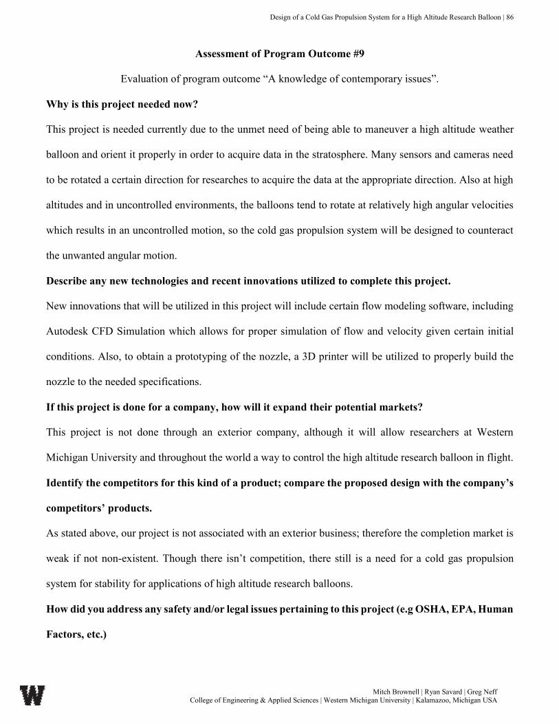
Design of a Cold Gas Propulsion System for a High Altitude Research Balloon | 86
Mitch Brownell | Ryan Savard | Greg Neff College of Engineering & Applied Sciences | Western Michigan University | Kalamazoo, Michigan USA
Assessment of Program Outcome #9
Evaluation of program outcome “A knowledge of contemporary issues”.
Why is this project needed now?
This project is needed currently due to the unmet need of being able to maneuver a high altitude weather
balloon and orient it properly in order to acquire data in the stratosphere. Many sensors and cameras need
to be rotated a certain direction for researches to acquire the data at the appropriate direction. Also at high
altitudes and in uncontrolled environments, the balloons tend to rotate at relatively high angular velocities
which results in an uncontrolled motion, so the cold gas propulsion system will be designed to counteract
the unwanted angular motion.
Describe any new technologies and recent innovations utilized to complete this project.
New innovations that will be utilized in this project will include certain flow modeling software, including
Autodesk CFD Simulation which allows for proper simulation of flow and velocity given certain initial
conditions. Also, to obtain a prototyping of the nozzle, a 3D printer will be utilized to properly build the
nozzle to the needed specifications.
If this project is done for a company, how will it expand their potential markets?
This project is not done through an exterior company, although it will allow researchers at Western
Michigan University and throughout the world a way to control the high altitude research balloon in flight.
Identify the competitors for this kind of a product; compare the proposed design with the company’s
competitors’ products.
As stated above, our project is not associated with an exterior business; therefore the completion market is
weak if not non-existent. Though there isn’t competition, there still is a need for a cold gas propulsion
system for stability for applications of high altitude research balloons.
How did you address any safety and/or legal issues pertaining to this project (e.g OSHA, EPA, Human
Factors, etc.)

Design of a Cold Gas Propulsion System for a High Altitude Research Balloon | 87
Mitch Brownell | Ryan Savard | Greg Neff College of Engineering & Applied Sciences | Western Michigan University | Kalamazoo, Michigan USA
Since there are regulations for high altitude objects by the Federal Communications Commission (FCC)
and the Federal Aviation Administration (FAA) our project must take into consideration these regulations.
The FCC limits cell phone tracking (GPS tracking using cellular wireless data), so the control system that
will be proposed for this system at a later date will account for that. Also, the FAA regulates that the weight
of privately launched research balloons will not exceed 12 lbs. Our design considerations will extensively
include this.
Are there any new standards or regulations on the horizon that could impact the development of this
project?
In regards to cold gas propulsion, new standards and regulation do not seem to be a problem in the future.
Though propulsive force can be created by plasma, new regulations could cover plasma propulsion systems
in the future, though the scope of the design project does not and should not include this.
Is there a potential for a new patent in your design? Please document related patents.
There are no current patents for applications of cold gas propulsion systems on high altitude research
balloons. There are a few patents that include the scope of micro-nozzles for cold gas propulsion and also
underwater cold gas propulsion systems; none of which apply directly to our project. There is a potential
for a patent once the entire system has been designed, including control systems for gas regulation and
stability control of the system in future design project that will not be covered in this design project

Design of a Cold Gas Propulsion System for a High Altitude Research Balloon | 88
Mitch Brownell | Ryan Savard | Greg Neff College of Engineering & Applied Sciences | Western Michigan University | Kalamazoo, Michigan USA
Assessment of Program Outcome #12
An understanding of the impact of the engineering solutions in a global, environmental and societal context
Is this project useful outside of the United States? Describe why it is or is not.
This project is most certainly useful outside of the United States. Not only will a cold gas propulsion system
allow for a better understanding of the high atmosphere, but it will allow for much more accurate data
collection and probing of the gas in the stratosphere. This will be of use outside of the United States due to
the fact that the entire world is concerned, and should be concerned, with the condition of the upper
atmosphere due to climate change, weather, ozone layer health, and many other factors.
Does your project comply with US and/or international standards or regulations? Which standards
are applicable?
As stated above, our project and further recommendations will include all necessary regulatory design
considerations regarding those of the FCC and the FAA. Pertaining to the international regulations, there
are standards that are different in nearly every country, though our design consideration will be thorough
enough to provide for a level necessary for the system to be legal in international travel.
Is this project restricted in its application to specific markets or communities? To which markets or
communities?
The project is not restricted to specific groups of people or individuals. Although the application will be
with respect to that of researches and research balloon rigs, there is no specified markets. There are FAA
and FCC regulations that must be complied with as well as permission by the FAA for the launch site and
launch duration, etc.
If the answer to any of the following is positive, explain how and, where relevant, what were your
actions to address the issues?
The design considerations have all been monitored and evaluated properly, and the outcome of the project
is expected to create productivity with respect to high altitude research.

Design of a Cold Gas Propulsion System for a High Altitude Research Balloon | 89
Mitch Brownell | Ryan Savard | Greg Neff College of Engineering & Applied Sciences | Western Michigan University | Kalamazoo, Michigan USA
Design is focused on serving the human needs. Design also can either negatively or positively influence
quality of life. Address the impact of your project on the following areas.
Air Quality?
The project will not negatively affect the air quality of the environment or atmosphere, as Nitrogen will be
used as propellant and nitrogen makes up the majority of ambient air. Due to the scale of the project, the
amount of nitrogen to affect air conditions is negligible.
Water Quality?
The scope of this project will not positively or negatively impact the quality of water on earth.
Food?
The scope of this project will not positively or negatively impact the supply, methods of supply, or anything
related to food.
Noise Level?
Though the design team is expecting a certain amount of noise created by the immediate drops in pressures
and flow, it will not affect the noise level in the stratosphere as the atmospheric air density is extremely low
and extremely distant from earth.
Does this project Impact:
Human health?
This project certainly impacts human health due to its assistance of helping researches gain data and
understanding of the upper atmospheric conditions of the earth. This directly relates to the health of humans
due to weather, climate change, condition of the ozone, and further understanding of how the human race
can adapt to these changes in the atmosphere.
Wildlife?
This project and/or any of its design consideration will not impact wildlife, though it can impact the way
researchers understand the way wildlife can adapt to the changes in the upper atmosphere as explained
above.

Design of a Cold Gas Propulsion System for a High Altitude Research Balloon | 90
Mitch Brownell | Ryan Savard | Greg Neff College of Engineering & Applied Sciences | Western Michigan University | Kalamazoo, Michigan USA
Vegetation?
The impact that this project has on vegetation is similar to the impact that this project has on human health,
as explain above only with application to vegetation.
Does this project improve?
Human Interaction?
This project does not directly improve how humans interact, although it does assist in the understanding of
the environment in which we are surrounded.
Well being?
This project indirectly improves society well-being due to the fact that researchers will develop a greater
understanding for the upper-atmospheric environment and how the human race can adapt. Since the cold
gas propulsion system will be able to orient the sensors and cameras properly, the high altitude research
balloons will be able to accurately acquire the data, and in turn researchers will further be able to assist in
the development of society without a barrier of uncontrollable sensors.
Safety?
This project and/or its design consideration does not directly improve the safety of anyone and/or anything
as it solely used for high altitude research applications.
Others?
As explained above, the indirect effects of the use of the cold gas propulsion system will allow for
researchers a better understanding of high altitude conditions which will in turn benefit all

Design of a Cold Gas Propulsion System for a High Altitude Research Balloon | 91
Mitch Brownell | Ryan Savard | Greg Neff College of Engineering & Applied Sciences | Western Michigan University | Kalamazoo, Michigan USA
Assessment of Program Outcome #13
A recognition of the need for, and ability to engage in life-long learning
Mitch Brownell
In detail identify the skills you bring to your design project that would be considered assets to the
project team.
Mitch Brownell brings a plethora of experience with fluids and flow with thermal applications regarding
sealing systems through internships. He also brings a steady work ethic and desire to learn. Also included
is a developing understanding of Autodesk Inventor modeling and FEA programming that will be utilized
in the analysis of the cold gas propulsion system frame and subcomponents.
Delineate the skills necessary to successfully execute your responsibilities on the project.
The skills needed on this project include many technical skills as well as project management and teamwork
skills. The technical skills include FEA, CFD, and CAD modeling. They also including a deep
understanding of fluid and thermal systems in order to successfully solve the design problem. The project
management skills are important to have a good understanding of the time frame of the project, as well as
the understanding of the tasks and being able to complete them.
Define the skills you will personally need to strengthen to achieve the task at hand.
The skills that Mitch Brownell wishes to achieve during this project is further understanding of the CFD
program and how that is related to thermal and fluid systems in a cold gas propulsion system. Other skills
that are sought after for development is working together in a design team and being able to a contributing
member of a design team to complete a common goal that will serve and industry need.
Explain how you plan to gain the skill level necessary to successfully execute your responsibilities to
the design team.
Through this process, Mr. Brownell plans to gain the skill level by being tentative to the task at hand and
being a productive and contributing member of the design team. Mr. Brownell also hopes to be able to

Design of a Cold Gas Propulsion System for a High Altitude Research Balloon | 92
Mitch Brownell | Ryan Savard | Greg Neff College of Engineering & Applied Sciences | Western Michigan University | Kalamazoo, Michigan USA
provide leadership during the Inventor FEA modeling portion of the design project, as well as be a
productive learner along with the teammates to achieve a common industry goal.
Ryan Savard
In detail identify the skills you are bringing to your design project that would be considered assets to
the project team.
Ryan Savard brings a variety of experience with industrial design and manufacturing through internships.
He also brings effective problem evaluation and solving skills which will be essential when dealing with a
relatively new topic to the design team. His developed ability to use solid works design software will be
crucial when it comes to conceptually designing and testing of this cold gas propulsion system using CFD
and further developing and building this cold gas propulsion system.
Delineate the skills necessary to successfully execute your responsibilities on the project.
The skills needed to successfully execute this project include technical skills, effective communication and
time management skills. These technical skills include FEA, CFD and CAD modeling. Technical skills
also include a vast understanding of fluid mechanics and thermal systems necessary to successfully solve
the assigned design problem. The communication and time management skills are necessary so that ample
time is allotted to gain a good understanding of the topics and deliver excellent research and design results.
Define your skills you will personally need to strengthen to achieve the task at hand.
The Skills that Ryan Savard desires to achieve during the duration of this project is to deepen his
understanding of fluid and thermal systems in application to a cold gas propulsion system. Other skills that
are being sought are a continued building of team leadership and management skills which will contribute
toward the success of the design group and future endeavors.
Explain how you plan to gain the skill level necessary to successfully execute your responsibilities to
the design team.
At the end of this process, Ryan plans to gain a widened knowledge base that will effectively contribute to
the design and success of this project. Mr. Savard also hopes to provide knowledge based in the fluid flow

Design of a Cold Gas Propulsion System for a High Altitude Research Balloon | 93
Mitch Brownell | Ryan Savard | Greg Neff College of Engineering & Applied Sciences | Western Michigan University | Kalamazoo, Michigan USA
analysis of the nozzle, as well as being an active learner along with his fellow team members to achieve a
common industrial goal.
Greg Neff
In detail identify the skills you are bringing to your design project that would be considered assets to
the project team.
Greg Neff brings a variety of experience with industrial design and manufacturing through his active
experiences working in the advanced Plasma Research Lab at Western Michigan University. He also brings
effective problem evaluation and solving skills which will be essential when dealing with a relatively new
topic to the design team. His developed ability to use Solid Works design software will be crucial when it
comes to conceptually designing and testing of this cold gas propulsion system using CFD and further
developing and building this cold gas propulsion system.
Delineate the skills necessary to successfully execute your responsibilities on the project.
The skills needed to successfully execute this project include technical skills, effective communication and
time management skills. The technical skills include FEA, CFD and CAD modeling. The technical skills
also include a vast understanding of fluid mechanics and thermal systems necessary to successfully solve
the assigned design problem. The communication and time management skills are necessary so that ample
time is allotted to gain a good understanding of the topics and deliver excellent research and design results.
Define your skills you will personally need to strengthen to achieve the task at hand.
The skills that Greg Neff desires to achieve during the duration of this project are a deepened understanding
of fluid and thermal systems in a cold gas propulsion system. Other skills that are being sought are a
continued building of team leadership and management skills which will contribute toward the success of
the design group and future endeavors.
Explain how you plan to gain the skill level necessary to successfully execute your responsibilities to
the design team.

Design of a Cold Gas Propulsion System for a High Altitude Research Balloon | 94
Mitch Brownell | Ryan Savard | Greg Neff College of Engineering & Applied Sciences | Western Michigan University | Kalamazoo, Michigan USA
At the end of this process, Greg plans to gain a widened knowledge base that will effectively contribute to
the design and success of this project. Mr. Neff also hopes to provide knowledge based in the fluid flow
analysis of the nozzle, as well as being an active learner along with his fellow team members to achieve a
common industrial goal.

Design of a Cold Gas Propulsion System for a High Altitude Research Balloon | 95
Mitch Brownell | Ryan Savard | Greg Neff College of Engineering & Applied Sciences | Western Michigan University | Kalamazoo, Michigan USA
APPENDIX F - RESUMES

Design of a Cold Gas Propulsion System for a High Altitude Research Balloon | 96
Mitch Brownell | Ryan Savard | Greg Neff College of Engineering & Applied Sciences | Western Michigan University | Kalamazoo, Michigan USA

Design of a Cold Gas Propulsion System for a High Altitude Research Balloon | 97
Mitch Brownell | Ryan Savard | Greg Neff College of Engineering & Applied Sciences | Western Michigan University | Kalamazoo, Michigan USA


![Gas Dynamics and Jet Propulsion[May2012]](https://img.pdfslide.us/doc/110x75/55cf9202550346f57b92b172/gas-dynamics-and-jet-propulsionmay2012.jpg)


![Gas Dynamics and Jet Propulsion[May2006]](https://img.pdfslide.us/doc/110x75/55cf9202550346f57b92add3/gas-dynamics-and-jet-propulsionmay2006.jpg)