Embed Size (px)
Citation preview
INTERNATIONAL JOURNAL OF PROFESSIONAL ENGINEERING STUDIES Volume VI /Issue 3 / JULY 2016
IJPRES
Design, Analysis and Simulation of Linear Controller of a STATCOM for Reactive Power Compensation on Variation of DC link Voltage by
the Application of STATCOM to Linear and Nonlinear Loads
1GINDAM GANGASAGARA, 2K.V.V.P.CHARI, 3DR. K. SUMANTH 1PG Scholar, Department of EEE, SNIST, Hyderabad, Telangana, India
2Associate Professor, Department of EEE, SNIST, Hyderabad, Telangana, India 3Professor of EEE & Principal, SNIST, Hyderabad, Telangana, India
Abstract- The STATCOM (Static synchronous Compensator) is a shunt connected voltage source converter using self-commutating device and can be effectively used for reactive power control. Its principle of operation is similar to that of a synchronous condenser. This paper describes the modeling of STATCOM along with the design of linear current and voltage controllers. The design of controllers for the converters can be realized in two ways. The first method is a non linear realization, which results in simple control rules with faster dynamics. The second method is a linear method, which requires system modeling. The second approach is adopted and simulated waveforms are presented in the paper. The designed controllers with variation of DC link voltage have been applied to the STATCOM and suitable DC link voltage has been selected on basis of spike and over shoot of the responses. And also we are using STATCOM with nonlinear load instead of linear load to eliminate current harmonics. All responses are obtained through MATLAB SIMULINK tool box and presented here for clarity of the control strategy.
Keywords - Controller design, PI Controller, STATCOM, Linear load and Nonlinear load.
I. INTRODUCTION Reactive power compensation is an important issue in the
control of electric energy systems. Reactive power increases the transmission system losses, reduces the power transmission capability of the transmission lines and can cause large amplitude of the variations in the receiving-end voltage. Moreover, rapid changes of the reactive power consumption of loads can cause voltage-amplitude oscillations (for instance, arc furnaces cause flicker). In addition, voltage variations can change the real power demand in the electric system, resulting in power oscillations. And also Now-a-days power systems have become very complex with interconnected long distance transmission lines [1-3]. The interconnected Grids become unstable as the heavy loads vary dynamically in their magnitude and phase angle and hence power factor [4-6]. Commissioning new transmission systems are extremely expensive and take considerable amount of time to build up. Therefore, in order to meet increasing power demands, utilities must rely on power export/import arrangements through the existing transmission systems. The capacitor banks are used to improve power factor but having a number of disadvantages [7].Power electronic devices are gaining popularity for applications in the field of power transmission and distribution systems.The reactive power (VAR)
compensation and control have been recognized [8] as an efficient & economic means of increasing power system transmission capability and stability. Power Electronic Devices are gaining increasing popularity for applications in the field of power transmission and distribution systems. The availability of semiconductor devices such as thyristors and gate turn-off thyristors (GTO) in suitable ratings makes such applications feasible. Also the tight constraints on right of way and the expense associated with building generation plants result in the need to use the existing networks more efficiently. High Voltage DC (HVDC) Transmission and conventional Static VAR Compensators (SVC) have been used around for a long time. The reactive power (VAR) compensation and control have been recognized [8-11] as an efficient & economic means of increasing power system transmission capability and stability. The FACTS (Flexible AC Transmission Systems) devices, such as STATCOM has been introduced more recently which employs a VSI with a fixed DC link capacitor as a static replacement of the synchronous condenser. In a traditional synchronous condenser, the field current of the synchronous motor controls the amount of VAR absorbed/injected and hence in a similar way, the firing instant of the 3-phase inverter controls the VAR into or out of the STATCOM.
Large numbers of capacitor banks or inductor banks are no more required. Only a fixed set of capacitor provides the required VAR control, with a rapid control of bus voltage and improvement of utility power factor. It offers several advantages over conventional thyristorised converters [12] in terms of speed of response. The penalty paid for this improvement is in terms of introduction of some harmonics, which requires separate handling using active filtration techniques.
Moran et al [13] have shown in details how the utilization of Sinusoidal Pulse Width Modulation (SPWM) techniques reduces harmonic distortion. It has also been shown that an increase of modulation index reduces the size of the link reactor and stress on switches which are significant issues in practical implementation. The modeling and analysis of STATCOM steady state and dynamic performance with conventional control method have been studied by Schauder and Mehta [14] using non-linear controller. In [15] the dynamic responses and steady state behavior of STATCOM with Space Vector Pulse Width Modulation (SVPWM) has
INTERNATIONAL JOURNAL OF PROFESSIONAL ENGINEERING STUDIES Volume VI /Issue 3 / JULY 2016
IJPRES
been studied and the advantages of introducing SVPWM inverter with higher values of modulation index are highlighted.
The controllable reactive power allows for a rapid control of bus voltage and power factor at the system or at the load end. To compensate for the distorted current drawn by the rectifiers from the utility grid, the STATCOM and its current controller must have the capability to track source PWM (Pulse Width Modulation) converters. The linear control is more suitable for STATCOM application reported in [16-17-20-21]. The present paper suggests the design of a linear current controller and voltage controller on the basis of gain and time constant adjustment along with the parameter of the coupling inductor and storage capacitor. These controllers are used in STATCOM and control the reactive power for improvement of power factor on variation of DC link voltage. DC link voltage is very important factor for operating STATCOM to fulfil the objective.
The present paper goes on to develop a closed loop model for investigating transient performance of the STATCOM by using controller parameter. First, in Section 2 focuses on state space model of the STATCOM with the system. Secondly, in Section 3, a current, voltage controllers are designed and the STATCOM is developed by using these controllers and then this STATCOM is connected to grid ,linear and nonlinear loads. The simulated responses with the designed controller parameters on variation of DC link voltage are presented. This scheme is both an extension and a significant improvement of the scheme suggested by Shauder et al [14] and Sensarma et al [18].The results obtained have been compared and appropriate conclusions have been drawn.
II. MODELING OF THE STATCOM AND ANALYSIS
A. Operating Principle: As is well known, the STATCOM is, in principle, a static
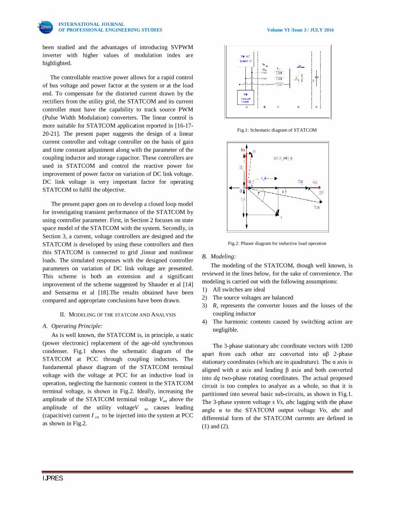
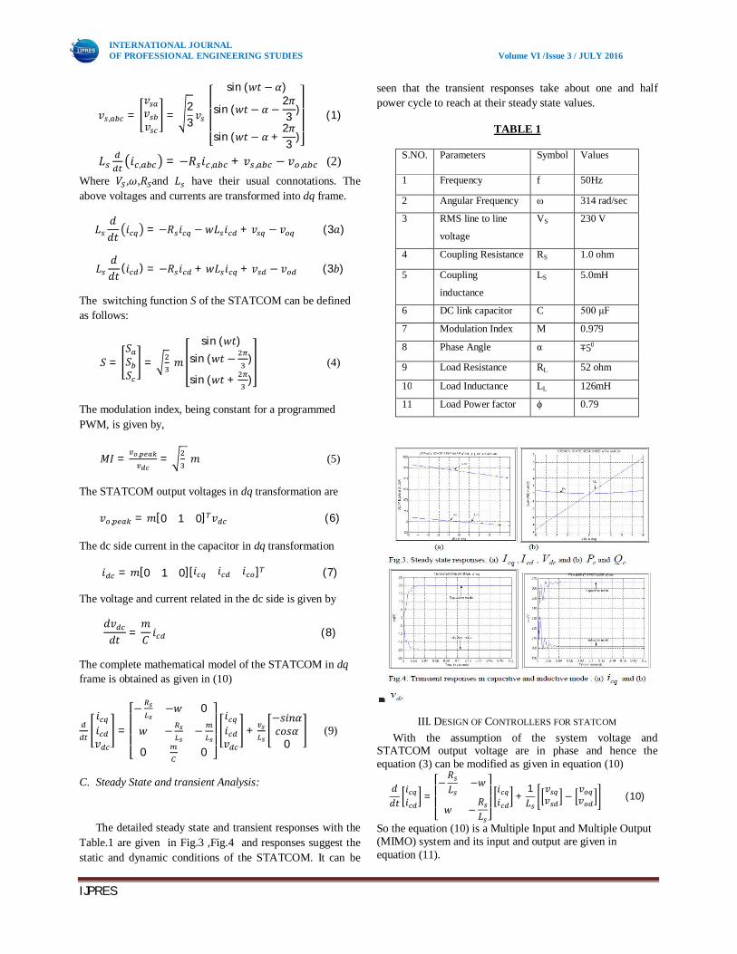
(power electronic) replacement of the age-old synchronous condenser. Fig.1 shows the schematic diagram of the STATCOM at PCC through coupling inductors. The fundamental phasor diagram of the STATCOM terminal voltage with the voltage at PCC for an inductive load in operation, neglecting the harmonic content in the STATCOM terminal voltage, is shown in Fig.2. Ideally, increasing the amplitude of the STATCOM terminal voltage Voa above the amplitude of the utility voltageV sa causes leading (capacitive) current I ca to be injected into the system at PCC as shown in Fig.2.
Fig.1: Schematic diagram of STATCOM
Fig.2: Phasor diagram for inductive load operation
B. Modeling: The modeling of the STATCOM, though well known, is
reviewed in the lines below, for the sake of convenience. The modeling is carried out with the following assumptions: 1) All switches are ideal 2) The source voltages are balanced 3) Rs represents the converter losses and the losses of the
coupling inductor 4) The harmonic contents caused by switching action are
negligible. The 3-phase stationary abc coordinate vectors with 1200
apart from each other are converted into αβ 2-phase stationary coordinates (which are in quadrature). The α axis is aligned with a axis and leading β axis and both converted into dq two-phase rotating coordinates. The actual proposed circuit is too complex to analyze as a whole, so that it is partitioned into several basic sub-circuits, as shown in Fig.1. The 3-phase system voltage s Vs, abc lagging with the phase angle α to the STATCOM output voltage Vo, abc and differential form of the STATCOM currents are defined in (1) and (2).
INTERNATIONAL JOURNAL OF PROFESSIONAL ENGINEERING STUDIES Volume VI /Issue 3 / JULY 2016
IJPRES
푣 , =푣푣푣
=23푣
⎣⎢⎢⎢⎡
sin (푤푡 − 훼)
sin (푤푡 − 훼 −2휋3 )
sin (푤푡 − 훼 +2휋3 )⎦
⎥⎥⎥⎤
(1)
퐿 푖 , = −푅 푖 , + 푣 , − 푣 , (2) Where 푉 ,휔,푅 and 퐿 have their usual connotations. The above voltages and currents are transformed into dq frame.
퐿푑푑푡
푖 = −푅 푖 − 푤퐿 푖 + 푣 − 푣 (3푎)
퐿푑푑푡
(푖 ) = −푅 푖 + 푤퐿 푖 + 푣 − 푣 (3푏)
The switching function S of the STATCOM can be defined as follows:
푆 =푆푆푆
= 푚
sin (푤푡)sin (푤푡 − )
sin (푤푡 + ) (4)
The modulation index, being constant for a programmed PWM, is given by,
푀퐼 = , = 푚 (5)
The STATCOM output voltages in dq transformation are
푣 , = 푚[0 1 0] 푣 (6)
The dc side current in the capacitor in dq transformation
푖 = 푚[0 1 0][푖 푖 푖 ] (7)
The voltage and current related in the dc side is given by
푑푣푑푡 =
푚퐶 푖 (8)
The complete mathematical model of the STATCOM in dq frame is obtained as given in (10)
푖푖푣
=
⎣⎢⎢⎢⎡− −푤 0
푤 − −
0 0 ⎦⎥⎥⎥⎤ 푖푖푣
+−푠푖푛훼푐표푠훼
0 (9)
C. Steady State and transient Analysis:
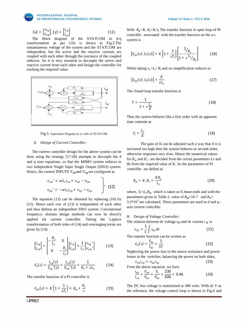
The detailed steady state and transient responses with the Table.1 are given in Fig.3 ,Fig.4 and responses suggest the static and dynamic conditions of the STATCOM. It can be
seen that the transient responses take about one and half power cycle to reach at their steady state values.
TABLE 1
S.NO. Parameters Symbol Values
1 Frequency f 50Hz
2 Angular Frequency ω 314 rad/sec
3 RMS line to line
voltage
VS 230 V
4 Coupling Resistance RS 1.0 ohm
5 Coupling
inductance
LS 5.0mH
6 DC link capacitor C 500 μF
7 Modulation Index M 0.979
8 Phase Angle α ∓50
9 Load Resistance RL 52 ohm
10 Load Inductance LL 126mH
11 Load Power factor ϕ 0.79
III. DESIGN OF CONTROLLERS FOR STATCOM With the assumption of the system voltage and
STATCOM output voltage are in phase and hence the equation (3) can be modified as given in equation (10)
푑푑푡
푖푖 =
⎣⎢⎢⎡−푅퐿
−푤
푤 −푅퐿 ⎦⎥⎥⎤ 푖푖 +
1퐿
푣푣 −
푣푣 (10)
So the equation (10) is a Multiple Input and Multiple Output (MIMO) system and its input and output are given in equation (11).
INTERNATIONAL JOURNAL OF PROFESSIONAL ENGINEERING STUDIES Volume VI /Issue 3 / JULY 2016
IJPRES
[푢] =푣푣 , [푦] =
푖푖 (11)
The block diagram of the STATCOM in d-q transformation as per (10) is shown in Fig.5.The instantaneous voltage of the system and the STATCOM are independent, but the active and the reactive currents are coupled with each other through the reactance of the coupled inductor. So it is very essential to decouple the active and reactive current from each other and design the controller for tracking the required value.
Fig.5: Equivalent Diagram on a.c.side of STATCOM
A. Design of Current Controller:
The current controller design for the above system can be done using the strategy [17-20] attempts to decouple the d and q axes equations, so that the MIMO system reduces to two independent Single Input Single Output (SISO) system. Hence, the control INPUTS Vod and Voq are configured as
푣 ∗ = 푤퐿 푖 + 푣 − 푣
푣 ∗ = −푤퐿 푖 + 푣 − 푣
The equation (13) can be obtained by replacing (10) by (12). Hence each row of (13) is independent of each other and thus defines an independent SISO system. Conventional frequency- domain design methods can now be directly applied for current controller. Taking the Laplace transformation of both sides of (14) and rearranging terms are given by (14).
푖푖 =
⎣⎢⎢⎡−푅퐿 0
0 −푅퐿 ⎦⎥⎥⎤ 푖푖 +
1퐿
푣 ∗
푣 ∗ (13)
퐺 (푠) =퐼 (푠)푉 ∗(푠) =
퐼 (푠)푉 ∗(푠) =
1푅 + 푠퐿 (14)
The transfer function of a PI controller is
퐺 (푠) = 퐾 1 +1푠푇 = 퐾 +
퐾푠 (15)
With Kp=K, Ki=K/τi The transfer function in open loop of PI controller associated with the transfer function on the a.c. system is
퐺 (푠).퐺 (푠) = 퐾 1 +1푠푇
1푅
1 + 푠 퐿 푅 (16)
While taking τi =Ls/ Rs and on simplification reduces to
퐺 (푠).퐺 (푠) =퐾푠퐿 (17)
The closed loop transfer function is
푇 =1
1 + 푠 퐿퐾 (18)
Thus the system behaves like a first order with an apparent time constant as
푇 =퐿퐾 (19)
The gain of K can be adjusted such a way that if it is increased too high then the system behaves as second order, otherwise responses very slow. Hence the numerical values for K p and K i are decided from the circuit parameters Ls and Rs from the required value of K. So the parameters of PI controller are defind as
퐾 = 퐾,퐾 =퐾푅퐿 (20)
where, Ti=Ls/Kp which is taken as 0.3mseconds and with the parameters given in Table.1, value of Kpi=16.7 and Kii= 3.3*103 are calculated. These parameters are used in d and q - axis current controller.
B. Design of Voltage Controller: The relation between dc voltage vdc and dc current i dc is
푣 =1퐶 푖 푑푡 (21)
The transfer function can be written as
퐺 (푠) =푉퐼 =
1푆퐶 (22)
Neglecting the power loss in the source resistance and power losses in the switches, balancing the power on both sides,
푣 푖 = 푣 푖 (23) From the above equation, we have
푖푖 =
푉푉 =
푉푉 =
230500 = 0.46 (24)
The DC bus voltage is maintained at 400 volts. With dc V as the reference, the voltage control loop is shown in Fig.6 and
(12)
INTERNATIONAL JOURNAL OF PROFESSIONAL ENGINEERING STUDIES Volume VI /Issue 3 / JULY 2016
IJPRES
it consists of inner d - axis current control loop. The active power is supplied by the d -axis current which is nothing but the ripple current of the capacitor. To make the steady state error of the voltage loop zero Proportional control is adopted here and it produces the reference d -axis current for the control of the d -axis current. The design of voltage controller is as follows: Then Proportional Integral controller is considering for the voltage control.
Hence, the transfer function of PI controller in(25) is associated with the transfer function on dc side is
Fig.6: DC link voltage control loop
퐺 (푠).퐺 (푠) = 퐾 1 +1푠푇 (25)
After taking Tv = C and on simplification
퐺 (푠).퐺 (푠) = 퐾1 + 푠푇푆 푇
(26)
The transfer function in closed loop
퐺 (푠).퐺 (푠) =1 + 푠푇
1 + 푠푇 + 푆 푇퐾
(27)
So the system behaves like a second order system. As Tv>>Tv
2/K and magnitude plot in Fig.14 shows the initial slop at break point is approximately –20db/decade and hence it reduces to first order system. The value of K can be determined form root locus with approximate settling time as
퐾 = 퐾 = 0.15,퐾 =퐾퐶
= 200 (28)
IV. SIMULATION RESULTS In this paper we take linear and nonlinear load and the
results are compared by means of STATCOM application. And the reactive power is compensated on variation of DC link Voltage.
A. Linear Load: Linear load Could be inductive or capacitive or
Resistive, Inductive or Resistive, capacitive .In this paper we take RL load R and L parameters are given in Table.1.
B. Nonlinear Load:
Usually an equipment with Diode and Capacitor.said to be Nonlinear load.Load parameters are given in table.2 In this paper we take a converter having diodes and RL load.
TABLE 2
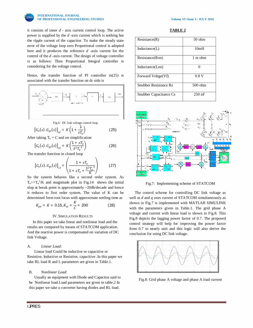
Fig.7: Implementing scheme of STATCOM
The control scheme for controlling DC link voltage as well as d and q axes current of STATCOM simultaneously as shown in Fig.7 is implemented with MATLAB SIMULINK with the parameters given in Table.1. The grid phase A voltage and current with linear load is shown in Fig.8. This Fig.8 depicts the lagging power factor of 0.7. The proposed control strategy will help for improving the power factor from 0.7 to nearly unit and this logic will also derive the conclusion for using DC link voltage.
Fig.8: Grid phase A voltage and phase A load current
Resistance(R)
50 ohm
Inductance(L)
10mH
Resistance(Ron)
1 m ohm
Inductance(Lon)
0
Forward Voltge(Vf)
0.8 V
Snubber Resistance Rs
500 ohm
Snubber Capacitance Cs
250 nF
INTERNATIONAL JOURNAL OF PROFESSIONAL ENGINEERING STUDIES Volume VI /Issue 3 / JULY 2016
IJPRES
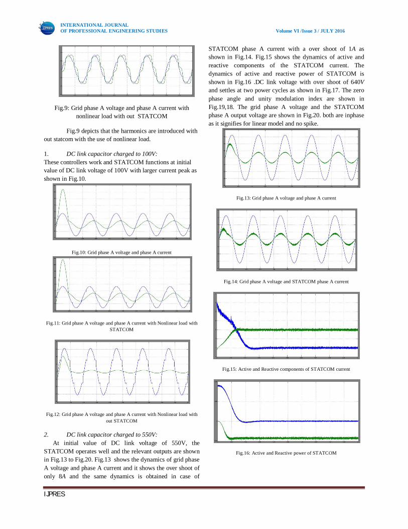
Fig.9: Grid phase A voltage and phase A current with nonlinear load with out STATCOM
Fig.9 depicts that the harmonics are introduced with out statcom with the use of nonlinear load.
1. DC link capacitor charged to 100V: These controllers work and STATCOM functions at initial value of DC link voltage of 100V with larger current peak as shown in Fig.10.
Fig.10: Grid phase A voltage and phase A current
Fig.11: Grid phase A voltage and phase A current with Nonlinear load with STATCOM
Fig.12: Grid phase A voltage and phase A current with Nonlinear load with out STATCOM
2. DC link capacitor charged to 550V: At initial value of DC link voltage of 550V, the
STATCOM operates well and the relevant outputs are shown in Fig.13 to Fig.20. Fig.13 shows the dynamics of grid phase A voltage and phase A current and it shows the over shoot of only 8A and the same dynamics is obtained in case of
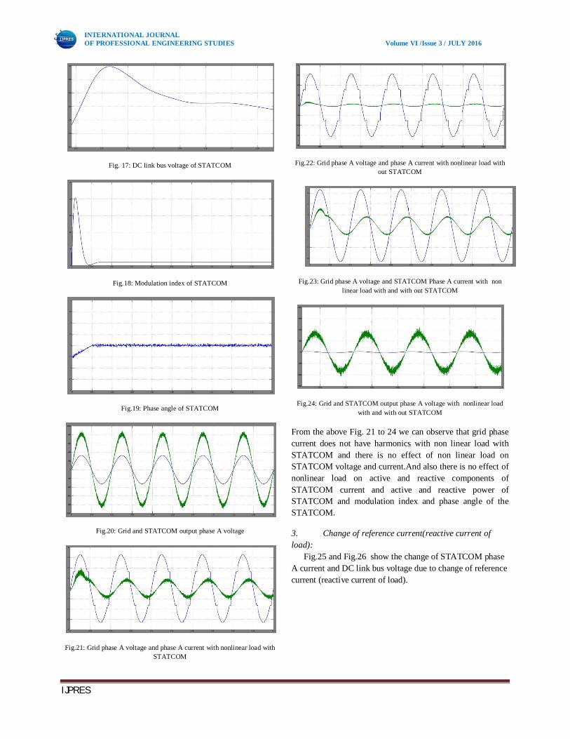
STATCOM phase A current with a over shoot of 1A as shown in Fig.14. Fig.15 shows the dynamics of active and reactive components of the STATCOM current. The dynamics of active and reactive power of STATCOM is shown in Fig.16 .DC link voltage with over shoot of 640V and settles at two power cycles as shown in Fig.17. The zero phase angle and unity modulation index are shown in Fig.19,18. The grid phase A voltage and the STATCOM phase A output voltage are shown in Fig.20. both are inphase as it signifies for linear model and no spike.
Fig.13: Grid phase A voltage and phase A current
Fig.14: Grid phase A voltage and STATCOM phase A current
Fig.15: Active and Reactive components of STATCOM current
Fig.16: Active and Reactive power of STATCOM
INTERNATIONAL JOURNAL OF PROFESSIONAL ENGINEERING STUDIES Volume VI /Issue 3 / JULY 2016
IJPRES
Fig. 17: DC link bus voltage of STATCOM
Fig.18: Modulation index of STATCOM
Fig.19: Phase angle of STATCOM
Fig.20: Grid and STATCOM output phase A voltage
Fig.21: Grid phase A voltage and phase A current with nonlinear load with STATCOM
Fig.22: Grid phase A voltage and phase A current with nonlinear load with out STATCOM
Fig.23: Grid phase A voltage and STATCOM Phase A current with non linear load with and with out STATCOM
Fig.24: Grid and STATCOM output phase A voltage with nonlinear load with and with out STATCOM
From the above Fig. 21 to 24 we can observe that grid phase current does not have harmonics with non linear load with STATCOM and there is no effect of non linear load on STATCOM voltage and current.And also there is no effect of nonlinear load on active and reactive components of STATCOM current and active and reactive power of STATCOM and modulation index and phase angle of the STATCOM.
3. Change of reference current(reactive current of load):
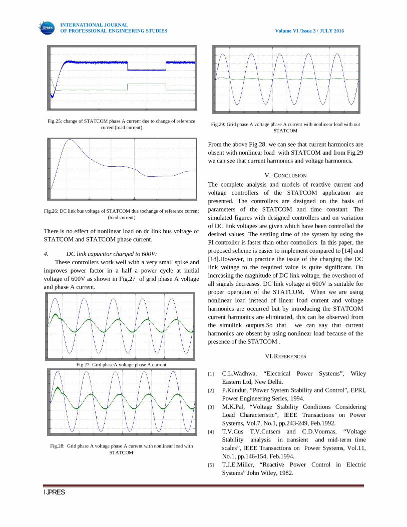
Fig.25 and Fig.26 show the change of STATCOM phase A current and DC link bus voltage due to change of reference current (reactive current of load).
INTERNATIONAL JOURNAL OF PROFESSIONAL ENGINEERING STUDIES Volume VI /Issue 3 / JULY 2016
IJPRES
Fig.25: change of STATCOM phase A current due to change of reference current(load current)
Fig.26: DC link bus voltage of STATCOM due tochange of reference current (load current)
There is no effect of nonlinear load on dc link bus voltage of STATCOM and STATCOM phase current.
4. DC link capacitor charged to 600V: These controllers work well with a very small spike and
improves power factor in a half a power cycle at initial voltage of 600V as shown in Fig.27 of grid phase A voltage and phase A current.
Fig.27: Grid phaseA voltage phase A current
Fig.28: Grid phase A voltage phase A current with nonlinear load with STATCOM
Fig.29: Grid phase A voltage phase A current with nonlinear load with out STATCOM
From the above Fig.28 we can see that current harmonics are obsent with nonlinear load with STATCOM and from Fig.29 we can see that current harmonics and voltage harmonics.
V. CONCLUSION The complete analysis and models of reactive current and voltage controllers of the STATCOM application are presented. The controllers are designed on the basis of parameters of the STATCOM and time constant. The simulated figures with designed controllers and on variation of DC link voltages are given which have been controlled the desired values. The settling time of the system by using the PI controller is faster than other controllers. In this paper, the proposed scheme is easier to implement compared to [14] and [18].However, in practice the issue of the charging the DC link voltage to the required value is quite significant. On increasing the magnitude of DC link voltage, the overshoot of all signals decreases. DC link voltage at 600V is suitable for proper operation of the STATCOM. When we are using nonlinear load instead of linear load current and voltage harmonics are occurred but by introducing the STATCOM current harmonics are eliminated, this can be observed from the simulink outputs.So that we can say that current harmonics are obsent by using nonlinear load because of the presence of the STATCOM .
VI. REFERENCES [1] C.L.Wadhwa, “Electrical Power Systems”, Wiley
Eastern Ltd, New Delhi. [2] P.Kundur, “Power System Stability and Control”, EPRI,
Power Engineering Series, 1994. [3] M.K.Pal, “Voltage Stability Conditions Considering
Load Characteristic”, IEEE Transactions on Power Systems, Vol.7, No.1, pp.243-249, Feb.1992.
[4] T.V.Cus T.V.Cutsem and C.D.Vournas, “Voltage Stability analysis in transient and mid-term time scales”, IEEE Transactions on Power Systems, Vol.11, No.1, pp.146-154, Feb.1994.
[5] T.J.E.Miller, “Reactive Power Control in Electric Systems” John Wiley, 1982.
INTERNATIONAL JOURNAL OF PROFESSIONAL ENGINEERING STUDIES Volume VI /Issue 3 / JULY 2016
IJPRES
[6] K.R.Padiyar, “Power System Dynamics - Stability and Control”, Interline Publishing Ltd, Bangalore, 1996.
[7] C.W.Taylor and A.L.V.Leuven, “CAPS: Improving Power System Stability Using the Time-Over voltage Capability of Large shunt Capacitor Banks”,IEEE Transactions on Power Delivery, Vol.11, No.2, pp.783-792, April 1996.
[8] A.T. Johns, A.Ter-Gazarian and D.F.Wame,”Flexible ac transmission systems (FACTS)”, IEE Power and Energy Series, London, U.K.
[9] Y.H. Song and A.T.John “Flexible AC Transmission Systems (FACTS)” IEE Power and Energy series Inc. 1999.
[10] N.G.Hingorani and L.Gyugyi, “Understanding FACTS”, IEEE PES, Sponsor, Standard publishers Distributors New Delhi,1999.
[11] R.M Mathur and R.K .Varma ,“ Thyristor based FACTS Controllers for Electrical Transmission Systems ”, IEEE power engineering society sponsored,Wiley interscience,2002.
[12] R.M.Mathur and R.K. Varma, “ Thyristors-based FACTS Controllers for Electrical Transmission Systems , IEEE Press ”, Wiley - Interscience Publication.
[13] L.T. Moran, P.D. Ziogas and G.Joos, “ Analysis and Design of a Three- Phase Synchronous Solid- State Var Compansator”, IEEE Trans . Industry Application, Vol. 25, No. 4, 1989, pp. 598-608.
[14] C. Shauder and H.Mehta, “ Vector analysis and control of advanced static VAR compensators”, IEE Proc, 140, No. 4, July 1993.
[15] M.Sengupta ,J.K Moharana and A.Sengupta,“ Study on an Advanced Static VAR Compensator switched from a Space Vector PWM inverter –Analysis, simulation and comparison with the conventional sinusoidal PWM , NPEC 2003, IIT Bombay,16-17 Oct 03 pp 72-78.
[16] D. M.Brod and D.W. Novotny, “ Current control of VSIPWM inverter ” IEEE Trans. Industrial Appl, Vol.IA-21,pp.562-570,July/Aug.1985.
[17] S. Buso , L . Malesani and P. Mattavelli , “Comparison of Current Control Techniques for Active Filter Application”IEEETrans.Industrial Electronics,Vol.45, No.5, pp.722-729, October 1998.
[18] P .S . sensarma , K .R. Padiyar and V. Ramnarayanan , “ Analysis and Performance Evaluation of a Distribution STATCOM for Compensating Voltage Fluctuations”, IEEE Transaction on Power Delivery, Vol.16, No.2, pp.259-264, April 2001.
[19] A .M . Kulkarni and K .R . Padiyara , “ Design of Reactive Current and Voltage Controllers of Static Condenser” , Power and Energy System , Vol.19, No.6, pp.397-410, 1997.
[20] S .K .Sethy and J .K .Moharana , “ Modeling , Design and Simulation of Current and Voltage Linear Controller of a STATCOM for Reactive Power Compensation”, NSPEES-12, Sept.29-30, GIET, BBSR, pp-37-44, 2012.
[21] S.K.Sethy and J.K.Moharana, “ Design and Simulation of Linear Model of a STATCOM for Reactive Power Compensation on variation of DC Link voltage”, IJEIT,Volume 2, Issue 5, November-2012, pp-183-189.