Embed Size (px)
Citation preview

IJSRD - International Journal for Scientific Research & Development| Vol. 4, Issue 07, 2016 | ISSN (online): 2321-0613
All rights reserved by www.ijsrd.com 133
Design, Analysis and Optimization of Four Stroke S.I. Engine Connecting
Rod using Finite Element Analysis with the help of CAE and CAD
Software Ankit Kumar Pandey1 Prof. Sandeep Jain2 Dr. Lokesh Bajpai3
1M.E. Student 2Associate Professor 3Head of Department 1,2,3Department of Mechanical Engineering
1,2,3Samrat Ashok Technological Institute, Vidisha 464001, IndiaAbstract— The aim of this paper is to design, analysis and
optimization of connecting rod which is stronger and light-
weight with respect to existing connecting rod with the help
of CAE and CAD Software. Static structural analysis is
done to analyze stresses, strain, total deformation and factor
of safety distribution in various parts of the connecting rod
to known the effect due to maximum compressive loading
using ANSYS 16.2. Solid parametric models of connecting
rod have been made using CATIA V5R20. In this study
advance materials, aluminium alloy A16T, titanium alloy
Ti-6Al-4V, and carbon-fibre reinforced polymer material are
used to replace the existing material of connecting rod.
These materials have very high strength in compression as
well as in tension and have low density 3 to 4 times less than
existing forged steel material. Therefore, by replacing
existing connecting rod material (forged steel) with these
advance materials connecting rod weight will reduce and
factor of safety will increase. Shape optimization module is
used for weight optimization of the existing connecting rod.
Fatigue analysis is done for aluminium alloy connecting rod.
Connecting rod made of aluminium alloy A16T, titanium
alloy Ti-6Al-4V and carbon-fibre reinforced polymer
material has weight reduction percentage with respect to
existing material (forged steel) is 59.12%, 48.59% and
77.01% respectively. Factor of safety for connecting rod
made of forged steel, aluminium alloy A16T, titanium alloy
Ti-6Al-4V and carbon-fibre reinforced polymer material is
1.8348, 1.1562, 2.2056 and 2.4299 respectively. Fatigue life
for aluminium alloy connecting rod under the effect of
extreme peak compressive gas loading is 99507 cycles and
when load is half its minimum life is 108 cycles.
Key words: S.I. engine connecting rod; weight optimization;
Static structural analysis; CAE and CAD
I. INTRODUCTION
The connecting rod is the intermediate member between the
piston and the crankshaft. It consists of a long shank, a small
end, and a big end. The cross-section of the shank may be
rectangular, tubular, circular, H-section or I-section.
Generally, a circular section is used for low speed engines
while I-section is preferred for high speed engines. Its
primary function is to transmit the power from the piston pin
to the crankpin and thus convert the reciprocating motion of
the piston into the rotary motion of the crank.
Static structural analysis is used to determine the
distribution of displacements, stresses, strains, factor of
safety and forces in components of connecting rod caused
by extreme peak compressive gas loading that do not induce
significant inertia and damping effects.
Shape optimization is used for performing weight-
reduction on existing design. The Shape Finder tries to find
areas where material can be removed without adversely
affecting the strength of the overall structure.
A. Nomenclature
dc Inner diameter of big End
Dc Outer diameter of big End
dp Inner diameter of small End
Dp Outer diameter of small End
n Number of working stroke per minute
Pbp Bearing pressure at big End
Pcp Allowable bearing pressure for piston pin bearing
T Thickness of I section flange
𝜎c Compressive yield strength
Table 1:
II. LITERATURE REVIEW
R.J. Yang et al, described process of shape optimization for
connecting rod upper end (pin end), in their paper they
optimized upper end (pin end) of connecting rod. They
clamped shank of connecting rod, and a uniformly pressure
100 MPa is applied at pin end to simulate the firing force.
Critical stress used for analysis is chosen as 1000 MPa in
two different models. In first model (first case) they took 5
design parameters and optimized volume from 8114 mm2
with 3% stress violation (3% over critical stress) to 7183
mm2 with no stress violation, in second case they took 10
design parameters and optimized volume from 6395 mm2
with 41% stress violation to 7140 mm2 with 2% violation. In
second model design is identical as first model and velocity
is updated for each iteration. They optimized volume from
8114 mm2 with 3% stress violation to 7235 mm2 with 2%
stress validation. [1]
M. Omid et al, Calculated displacements and
stresses under the Maximum compression and tension
loading in the connecting rod of universal tractor (U650). In
their paper they find out critical point of connecting rod of
U650 is end of the shank and near piston hole in tension and
compression loading. That Result is useful for modification
of connecting rod. [2]
Mohammed Mohsin Ali et al, in their paper fatigue
life calculated due to concentrated load and cosine type load
distribution on the bigger end of connecting rod. They
applied contact pressure 54 N/mm2 at the piston pin end, 16
N/mm2 at the crank pin end, they constrained shank of
connecting rod and calculated Alternating stress =139.58
N/mm2, Cycles used/allowed = 0.1000e+07/ 0.1000e+07
and Cumulative fatigue usage = 1.00000. [3]
D.Gopinatha et al, in their paper they deal with two
points, first, static load stress analysis of the connecting rod
for forged steel, aluminium and titanium materials, and
second, optimization for weight of forged steel connecting
rod by 10.38% for the same strength. [4]

Design, Analysis and Optimization of Four Stroke S.I. Engine Connecting Rod using Finite Element Analysis with the help of CAE and CAD Software
(IJSRD/Vol. 4/Issue 07/2016/033)
All rights reserved by www.ijsrd.com 134
Heinz K. Junker, He directed the areas of
development, design, and maintenance of engines,
technology, thermodynamics, and vehicle construction, in
modern gasoline and diesel engines also describe complete
knowledge of S.I. engine components. In this book
explained purpose and function, Boundary conditions
(forces, stress, and temperature), design detail, numerical
simulations and F.E. Analysis, materials, Coating and
surface treatment for piston rings, piston pin and piston pin
clipper, bearings, connecting rod, crankcase and cylinder
linear. [5]
III. DESIGN OF CONNECTING ROD
A. Configuration of Engine
In this paper single cylinder, 4 stroke, air cooled, SOHC,
TVS Scooty Pep+ bike engine configuration considers for
design and FE Analysis of connecting rod for three different
materials. Configuration of engine is shown in Table 1. [6] Cylinder bore, D 51mm
Stroke, L 43mm
Piston displacement 87.8cc
Compression ratio 10.1:1
Maximum power in KW, (IP) 3.68@6500 rpm
Maximum torque in Nm 5.80@4000 rpm
Maximum speed 60km/hr
Table 1: Configuration of engine
B. Standard Properties of I Section Connecting Rod
Standard properties of I section Connecting rod are
summarized in Table 2. [7] Depth of the section, H = 5t
Area of the section, A = 11t2
Depth of the section near the big end, H1 = 1.1H to 1.25H
Depth of the section near the small end, H2 = 0.75H to 0.9H
Moment of inertia about x axis, Ixx = (419/12)1t4
Moment of inertia about y axis, Iyy = (131/12)t4
Ixx/Iyy = 3.2
Radius of gyration of the section about X-axis,
KXX = 1.78t
Length of the crank pin, lc = 1.25dc to
1.5dc
Length of the piston pin, lp = 1.5dp to 2dp
Table 2: Standard properties of I section connecting rod
C. Dimension of Connecting Rod
Dimensions of connecting rod are calculated by shown
formulas: [7]
1) Piston Displacement area,
A = 𝜋×𝐷2
4 (1)
= 2042.8206 mm2
2) Mean effective pressure,
Pm = 60×IP
l×A×n (2)
= 0.7734 N/mm2
3) The Maximum gas Pressure, Pmax is taken as 9 to 10
times of mean effective pressure (Pm ),
PMAX = 0.7734×9 = 6.9606 = 6 N/mm2
4) The maximum force acting on the piston due to gas
pressure,
F = (𝜋×𝐷2×𝑃𝑀𝑎𝑥
4) (3)
= 12256.9236 N
5) Radius of gyration of the section about X-axis,
Kxx =
√419t4 × (1
12) × 11t2
(4)
= 1.78t
6) Length of the connecting rod,
l = Stroke×2 = 86 mm
7) Since factor of safety is considered as, FOS = 2.8995,
So Bulking load
WB= 1225.9236×2.8995 = 35545.085 N
From Rankine’s formula,
WB = σc×A
1+a(l/ Kxx)2 (5)
35545.085 = (415×11t2) / [1+0.0002(86/1.78t) 2]
t = 2.8688 mm
8) Width of the section,
B = 4t= 4 × 2.8688 = 11.4752 mm
9) Height of the section,
H = 5t = 5 × 2.8688 = 14.344 mm
lc = (1.25 to 1.5) dc and lp = (1.5 to 2) dp
10) Load on the crank pin, FL = dc × lc × Pcp
7109.628 = dc ×1.5×dC×8
dc = 24.34 mm
11) Outer diameter of the pin,
DC = (1.25 to 1.65) × dc = 40.161 mm
12) Load on the piston pin, FL = dp × lp × Pbp
13) 109.628 = dP×1.5×dbP×8
dp = 15.394 mm
14) Outer diameter of the pin,
DP = (1.25 to 1.65) × dp = 19.243 mm
15) Length of small End pin,
ls = (0.3 to 0.45) × D
0.3×51= 15.3 mm
16) Length of big End pin,
lc = (0.45 to 0.95) × D
0.58×24.34 = 14.1172 mm
17) Height near the big End,
H1 = (1.1 to 1.25)×H = 16.2 mm
18) Height near the small End,
H2 = (0.75 to 0.9)×H = 14.2 mm
The model of connecting rod is created in CATIA
as shown in figure 1, and drawing of connecting rod is
created in CATIA as shown in figure 2, as per the
dimensions of connecting rod.
The dimensions of the present connecting rod are
taken with the help of vernier caliper from the actual TVS
Scooty Pep+ connecting rod. Comparison of theoretical
dimensions to the actual dimensions calculated by engine
specifications are tabulates in table 3.
Fig. 1: Model of connecting rod in CATIA

Design, Analysis and Optimization of Four Stroke S.I. Engine Connecting Rod using Finite Element Analysis with the help of CAE and CAD Software
(IJSRD/Vol. 4/Issue 07/2016/033)
All rights reserved by www.ijsrd.com 135
Fig. 2: The Drawing of connecting rod is created in CATIA
Dimensions
Theoretical
Dimensions Values
(mm)
Actual Dimensions
Values (mm)
Outer diameter of
big End, Dc 40.161 40.5
Inner diameter of
big End, dc 24.34 -
Outer diameter of
small End, Dp 19.243 18.9
Inner diameter of
small End, dp 15.3 13.006
Thickness of the
flange, t 2.8688 2.87
Height near the big
End, H1 16.2 16.2
Height near the
small End, H2 14.2 14.2
Table 3: Comparison of dimensions of existing
connecting rod to the calculated theorectical diamensions
IV. FINITE ELEMENT ANALYSIS
The objective of FEA is to investigate stresses and problem
area experienced by the connecting rod. Forged steel
connecting rod is existing connecting rod for the FE
Analysis, since this connecting rod is also used for
optimization. Connecting rod is designed for long life where
stresses are mainly elastic. Therefore material properties of
forged steel, aluminium alloy A16T, titanium alloy Ti-6AI-
4V are tabulated in table 4, [8] the mechanical properties of
carbon-fibre reinforced polymer shown in table 5. [8]
Properties Forge
Steel
Aluminium
Alloy A16T
Titanium
Alloy Ti-6AI-
4V
Ultimate tensile
strength σB, Mpa 625 460 ≥930
Tensile yield
strength σ0.2, MPa 625 300 ≥862
Compressive yield
strength σ-0.2, MPa 415 285 917
Modulus of
Elasticity E, GPa 221 71 105-115
Poision ratio μ 0.29 0.33 0.36
Density 𝜌, g/cm3 7.7 2.8 4.43
Hardness, HBN 101 105 255-340
Table 4: Mechanical Properties of materials used for design
of connecting rod
In this study advance materials, aluminium alloy
A16T, titanium alloy Ti-6Al-4V, and carbon-fibre
reinforced polymer material are used, These materials have
very high strength in compression as well as in tension and
also have low density 3 to 4 times less than existing forged
steel material.
Properties Carbon fibreglass
monolayer material
Density ρ, g/cm3 2.0
Elastic Modulus in X Direction
Ex, GPa 125
Elastic Modulus in Y Direction
Ey, GPa 8.4
Poision ration in XY plan μxy 0.29
Poision ration in X plan μyx 0.29
Modulus of rigidity Gxy, GPa 4.3
Tensile strength in X direction
σ+x, Mpa 1050
Compressive strength in X
direction σ-x, Mpa 950
Tensile strength in Y direction
σ+y, Mpa 20
Compressive strength in Y
direction σ-y, MPa 120
Shear stress in XY plane τxy,
MPa 60
Table 5: Mechanical properties of carbon-fibre reinforced
polymer used for design of connecting rod
A. Meshed Model of Connecting Rod
Figure 3, shows meshed model of connecting rod in ANSYS
16.2. Tetrahedral element ware used for the solid mesh. In
table 6, shows meshing properties of existing connecting
rod. Number of nodes Number of elements Size of elements
22961 13405 4.5 mm
Table 6: Meshing properties of existing connecting rod
B. Boundary Conditions for Analysis of Connecting Rod
Using ANSYS
Figure 4, shows loads applied to model of connecting rod,
Pressure of 14 MPa is applied at small end and 8 MPa is
applied at big end. Thus in general practice connecting rod
is designed by assuming the force in the connecting equal to
the maximum force due to pressure, neglecting piston inertia
effect. The compressive force of 12256.9236 N was applied
at small end of the connecting rod.
Fig. 4: Boundary conditions for FEA in ANSYS
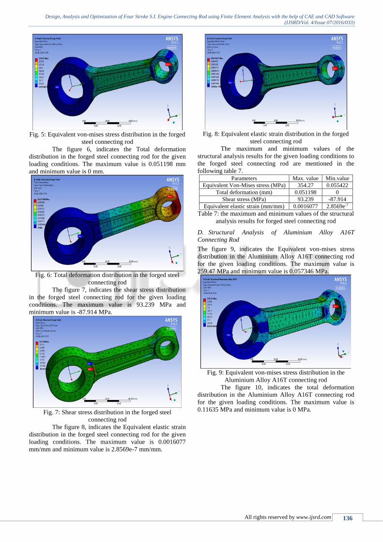
C. Structural Analysis of Forged Steel Connecting Rod
The figure 5, indicates the von-mises stress distribution in
the forged steel connecting rod for the given loading
conditions. The maximum value is 354.27 MPa and
minimum value is 0.055422 MPa.
Design, Analysis and Optimization of Four Stroke S.I. Engine Connecting Rod using Finite Element Analysis with the help of CAE and CAD Software
(IJSRD/Vol. 4/Issue 07/2016/033)
All rights reserved by www.ijsrd.com 136
Fig. 5: Equivalent von-mises stress distribution in the forged
steel connecting rod
The figure 6, indicates the Total deformation
distribution in the forged steel connecting rod for the given
loading conditions. The maximum value is 0.051198 mm
and minimum value is 0 mm.
Fig. 6: Total deformation distribution in the forged steel
connecting rod
The figure 7, indicates the shear stress distribution
in the forged steel connecting rod for the given loading
conditions. The maximum value is 93.239 MPa and
minimum value is -87.914 MPa.
Fig. 7: Shear stress distribution in the forged steel
connecting rod
The figure 8, indicates the Equivalent elastic strain
distribution in the forged steel connecting rod for the given
loading conditions. The maximum value is 0.0016077
mm/mm and minimum value is 2.8569e-7 mm/mm.
Fig. 8: Equivalent elastic strain distribution in the forged
steel connecting rod
The maximum and minimum values of the
structural analysis results for the given loading conditions to
the forged steel connecting rod are mentioned in the
following table 7. Parameters Max. value Min.value
Equivalent Von-Mises stress (MPa) 354.27 0.055422
Total deformation (mm) 0.051198 0
Shear stress (MPa) 93.239 -87.914
Equivalent elastic strain (mm/mm) 0.0016077 2.8569e-7
Table 7: the maximum and minimum values of the structural
analysis results for forged steel connecting rod
D. Structural Analysis of Aluminium Alloy A16T
Connecting Rod
The figure 9, indicates the Equivalent von-mises stress
distribution in the Aluminium Alloy A16T connecting rod
for the given loading conditions. The maximum value is
259.47 MPa and minimum value is 0.057346 MPa.
Fig. 9: Equivalent von-mises stress distribution in the
Aluminium Alloy A16T connecting rod
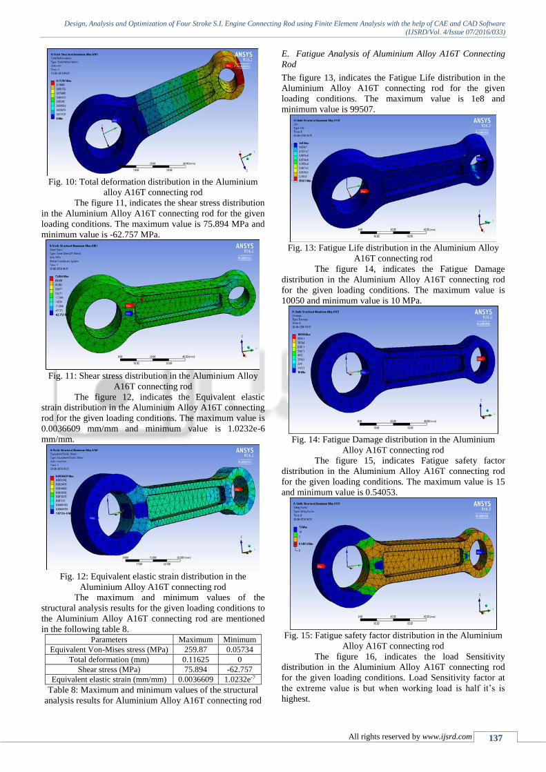
The figure 10, indicates the total deformation
distribution in the Aluminium Alloy A16T connecting rod
for the given loading conditions. The maximum value is
0.11635 MPa and minimum value is 0 MPa.
Design, Analysis and Optimization of Four Stroke S.I. Engine Connecting Rod using Finite Element Analysis with the help of CAE and CAD Software
(IJSRD/Vol. 4/Issue 07/2016/033)
All rights reserved by www.ijsrd.com 137
Fig. 10: Total deformation distribution in the Aluminium
alloy A16T connecting rod
The figure 11, indicates the shear stress distribution
in the Aluminium Alloy A16T connecting rod for the given
loading conditions. The maximum value is 75.894 MPa and
minimum value is -62.757 MPa.
Fig. 11: Shear stress distribution in the Aluminium Alloy
A16T connecting rod
The figure 12, indicates the Equivalent elastic
strain distribution in the Aluminium Alloy A16T connecting
rod for the given loading conditions. The maximum value is
0.0036609 mm/mm and minimum value is 1.0232e-6
mm/mm.
Fig. 12: Equivalent elastic strain distribution in the
Aluminium Alloy A16T connecting rod
The maximum and minimum values of the
structural analysis results for the given loading conditions to
the Aluminium Alloy A16T connecting rod are mentioned
in the following table 8. Parameters Maximum Minimum
Equivalent Von-Mises stress (MPa) 259.87 0.05734
Total deformation (mm) 0.11625 0
Shear stress (MPa) 75.894 -62.757
Equivalent elastic strain (mm/mm) 0.0036609 1.0232e-7
Table 8: Maximum and minimum values of the structural
analysis results for Aluminium Alloy A16T connecting rod
E. Fatigue Analysis of Aluminium Alloy A16T Connecting
Rod
The figure 13, indicates the Fatigue Life distribution in the
Aluminium Alloy A16T connecting rod for the given
loading conditions. The maximum value is 1e8 and
minimum value is 99507.
Fig. 13: Fatigue Life distribution in the Aluminium Alloy
A16T connecting rod
The figure 14, indicates the Fatigue Damage
distribution in the Aluminium Alloy A16T connecting rod
for the given loading conditions. The maximum value is
10050 and minimum value is 10 MPa.
Fig. 14: Fatigue Damage distribution in the Aluminium
Alloy A16T connecting rod
The figure 15, indicates Fatigue safety factor
distribution in the Aluminium Alloy A16T connecting rod
for the given loading conditions. The maximum value is 15
and minimum value is 0.54053.
Fig. 15: Fatigue safety factor distribution in the Aluminium
Alloy A16T connecting rod
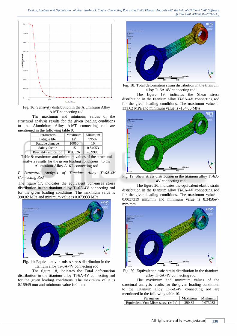
The figure 16, indicates the load Sensitivity
distribution in the Aluminium Alloy A16T connecting rod
for the given loading conditions. Load Sensitivity factor at
the extreme value is but when working load is half it’s is
highest.
Design, Analysis and Optimization of Four Stroke S.I. Engine Connecting Rod using Finite Element Analysis with the help of CAE and CAD Software
(IJSRD/Vol. 4/Issue 07/2016/033)
All rights reserved by www.ijsrd.com 138
Fig. 16: Sensivity distribution in the Aluminium Alloy
A16T connecting rod
The maximum and minimum values of the
structural analysis results for the given loading conditions
to the Aluminium Alloy A16T connecting rod are
mentioned in the following table 9. Parameters Maximum Minimum
Fatigue life 1e8 99507
Fatigue damage 10050 10
Safety factor 15 0.54053
Biaxiality indication 0.93526 -0.9998
Table 9: maximum and minimum values of the structural
analysis results for the given loading conditions to the
Aluminium Alloy A16T connecting rod
F. Structural Analysis of Titanium Alloy Ti-6A-4V
Connecting Rod
The figure 17, indicates the equivalent von-mises stress
distribution in the titanium alloy Ti-6A-4V connecting rod
for the given loading conditions. The maximum value is
390.82 MPa and minimum value is 0.073933 MPa
Fig. 11: Equivalent von-mises stress distribution in the
titanium alloy Ti-6A-4V connecting rod
The figure 18, indicates the Total deformation
distribution in the titanium alloy Ti-6A-4V connecting rod
for the given loading conditions. The maximum value is
0.15949 mm and minimum value is 0 mm.
Fig. 18: Total deformation strain distribution in the titanium
alloy Ti-6A-4V connecting rod
The figure 19, indicates the Shear stress
distribution in the titanium alloy Ti-6A-4V connecting rod
for the given loading conditions. The maximum value is
131.62 MPa and minimum value is -134.86 MPa
Fig. 19: Shear stress distribution in the titanium alloy Ti-6A-
4V connecting rod
The figure 20, indicates the equivalent elastic strain
distribution in the titanium alloy Ti-6A-4V connecting rod
for the given loading conditions. The maximum value is
0.0037319 mm/mm and minimum value is 8.3458e-7
mm/mm.
Fig. 20: Equivalent elastic strain distribution in the titanium
alloy Ti-6A-4V connecting rod
The maximum and minimum values of the
structural analysis results for the given loading conditions
to the Titanium alloy Ti-6A-4V connecting rod are
mentioned in the following table 10. Parameters Maximum Minimum
Equivalent Von-Mises stress (MPa) 390.82 0.073933

Design, Analysis and Optimization of Four Stroke S.I. Engine Connecting Rod using Finite Element Analysis with the help of CAE and CAD Software
(IJSRD/Vol. 4/Issue 07/2016/033)
All rights reserved by www.ijsrd.com 139
Total deformation (mm) 0.15949 0
Shear stress (MPa) 131.62 -134.86
Equivalent elastic strain (mm/mm) 0.0037319 8.3458e-7
Table 10: Maximum and minimum values of the titanium
alloy Ti-6A-4V connecting rod
G. Structural Analysis of Carbon-Fibre Reinforced
Polymer Connecting Rod
The figure 21, indicates the Equivalent von-mises stress
distribution in the Carbon-fibre reinforced polymer
connecting rod for the given loading conditions. The
maximum value is 390.96 MPa and minimum value is
0.0076823 Mpa.
Fig. 21: Equivalent von-mises stress distribution in the
Carbon fiberglass monolayer connecting rod
The figure 22, indicates the Total deformation
distribution in the Carbon-fibre reinforced polymer
connecting rod for the given loading conditions. The
maximum value is 2.0841 mm and minimum value is 0 mm.
Fig. 22: Total deformation distribution in the Carbon
fiberglass monolayer connecting rod
The figure 23, indicates the shear stress distribution
in the Carbon-fibre reinforced polymer connecting rod for
the given loading conditions. The maximum value is 167.08
MPa and minimum value is -148.86 MPa.
Fig. 23: Shear stress distribution in the Carbon-fibre
reinforced polymer connecting rod
The figure 24, indicates the Equivalent elastic
strain distribution in the Carbon-fibre reinforced polymer
connecting rod for the given loading conditions. The
maximum value is 0.051991 mm and minimum value is
1.5877e-6.
Fig. 24: Equivalent elastic strain distribution in the Carbon
fiberglass monolayer connecting rod
Table 11, Maximum and minimum values of the
structural analysis results for the given loading conditions
to the Aluminium Alloy A16T connecting rod Parameters Maximum Minimum
Equivalent Von-Mises stress (MPa) 390.96 0.0076823
Total deformation (mm) 2.0841 0
Shear stress (MPa) 167.08 -148.86
Equivalent elastic strain (mm/mm) 0.051991 1.5877e-6
Table 11: Maximum and minimum values of the titanium
aluminium alloy A16T connecting rod
V. COMPARISON OF CONNECTING ROD FOR DIFFERENT
MATERIALS
Comparisons of Increase in factor of safety and reduction in
mass of connecting rod of advance materials connecting rod
as compare to existing forged steel material connecting rod
is shown in graph also shown factor of safety and mass of
connecting rod designed for advance materials.

Design, Analysis and Optimization of Four Stroke S.I. Engine Connecting Rod using Finite Element Analysis with the help of CAE and CAD Software
(IJSRD/Vol. 4/Issue 07/2016/033)
All rights reserved by www.ijsrd.com 140
Fig. 25:
VI. OPTIMIZATION OF EXISTING CONNECTING ROD
The Objective of shape optimization task is to minimize
mass of connecting rod under the effect of extreme peak
compressive gas load, such that the maximum, minimum,
and Equivalent stress amplitude are within the limits of
allowable stresses. The buckling load factor under the peak
gas load has to be permissible. Optimized model of existing
connecting rod is shown in figure 25. Mathematically stated,
the optimization statement would appear as follows:
Objective: - Minimize Mass and Cost
Compressive load = peak compressive gas load.
Maximum Stress < Allowable Stress.
Side constraints (component dimension).
Fig. 25: optimized model of existing connecting rod
Detail of mass reduction after optimization of existing
connecting rod is shown in Table 12, Original Optimized Percentage of Reduction
0.16053 Kg 0.14434 Kg 10.085%
Table 12: Mass optimization of connecting rod
VII. CONCLUSION
From the static structural analysis it is observed that Von-
Mises stresses, shear stresses of forged steel, aluminium
alloy A16T, titanium alloy Ti-6AI-4V and carbon-fibre
reinforced polymer compared and it is observed that the
stresses are less in aluminium alloy A16T, moderate in
titanium alloy Ti-6AI-4V and carbon-fibre reinforced
polymer and high in forged steel for a given loading
conditions.
After carrying out static structural analysis the
stresses in loading condition were studied and then areas
where excess material can be removed were decided.
Optimization was performed to reduce weight of a forged
steel connecting rod subjected to the peak compressive gas
load.
Mass of the optimized connecting rod is 144.34 grams and
the optimized geometry is 10.85% light-weight than the
current connecting rod for the same strength.
Maximum von-misses stress for forged steel, aluminium
alloy A16T, titanium alloy Ti-6Al-4V and carbon-fibre
reinforced polymer materials is 354.27 MPa, 259 MPa,
390.82 MPa and 390.96 MPa respectively. Maximum
stresses are less than yield stress of their material so these
designs of connecting rod are safe.
Connecting rod made of aluminium alloy A16T, titanium
alloy Ti-6Al-4V and carbon-fibre reinforced polymer
materials has weight reduction percentage with respect to
existing material (forged steel) is 59.12%, 48.59% and
77.01% respectively.
Minimum factor of safety for connecting rod made of
forged steel, aluminium alloy, titanium alloy and carbon-
fibre reinforced polymer material is 1.8348, 1.1562,
2.2056 and 2.4299 respectively. Factor of safety is greater
than 1 at the extreme peak compressive gas loading.
Fatigue life at extreme peak compressive gas loading is
99507 cycles and when load is half minimum life is 108
cycles, here considering factor of safety is 2.89 so that
taken extreme peak compressive gas load is 2.89 times
greater than working load.
ACKNOWLEDGEMENTS
The authors sincerely thank to Department of Mechanical
Engineering, Samrat Ashok Technological Institute Vidisha
for support, co-operation and encouragement that enabled
this project.
REFERENCES
[1] R.J. Yang, D.L. Dewhirst, J.E. and A. Lee, "Shape
optimization of connecting rod pin end using a generic
model," Elsevier Science Publishers, pp. 257-264, 1992.
[2] M. Omid, S.S. Mohtasebi, S.A.Mirreri and E
Mahmoodi, "Fatigue analysis of connecting rod of
U650 Tractor in the finite elements code ANSYS,"
Journal of applied sciences, pp. 4338-4345, 2008.
[3] Mohammed Mohsin Ali H and Mohmed Haneef,
"Analysis of Fatigue Stresses on Connecting Rod
Subjected to Concentrated Loads At The Big End," in
4th International Conference on Materials Processing
and Characterization, INDIA, 2015.
[4] D.Gopinatha, Ch.V.Sushma, "Design and Optimization
of Four Wheeler Connecting Rod Using Finite Element
Analysis," in 4th International Conference on Materials
Processing and Characterization, India, 2015.
[5] H. K. Junker, Cylinder components, 1st ed., vol. 1, M.
GmbH, Ed., Wiesbaden: Vieweg+Teubner |GWV
Fachverlage GmbH, Wiesbaden , 2010, pp. 4-6.
[6] TVS Scooty Pept+ Engine specifications, "Engine
specifications" pp. 5.
[7] R.S.khurmi and J.K. gupta, "Internal combustion
Engine," in Machine design, delhi, EURASIA
PUBLISHING HOUSE (PVT.) LTD, 2005, pp. 1125-
1210.
[8] L. L. Myagkov, K. Mahkamov, N. D. Chainov, I.
Makhkamova, "Advanced and conventional internal
combustion engine materials," Woodhead Publishing
Limited, pp. 370-392, 2014.


![· flame, jive, star city - pheonix 125 new 2013 apache rtr 160 cc - new wego, jupitor, scooty zest . ignition coils for $ suzuki application ... re, all tvs motorcycles - all baja]](https://img.pdfslide.us/doc/110x75/5fa112d9a3b74c17c07b7b81/flame-jive-star-city-pheonix-125-new-2013-apache-rtr-160-cc-new-wego-jupitor.jpg)


![Untitled-2 [] ape.pdf · Customer Satisfaction Qualified Suppliers ... HONDA MOTORCYCLES HONDA ACTIVA TVS ACCESS TVS SCOOTY TVS XL SUPER . 3 Excellence in Quality 9-255 REAR WHELL](https://img.pdfslide.us/doc/110x75/5acc8eaa7f8b9a875a8cbf0b/untitled-2-apepdfcustomer-satisfaction-qualified-suppliers-honda-motorcycles.jpg)