Embed Size (px)
Citation preview

DESIGN, ANALYSIS AND FABRICATION OF REGENERATIVE AUTOMOTIVE
SUSPENSION SYSTEM TEST RIG MODULE
RAZLAN BIN RAZALI
UNIVERSITI TEKNIKAL MALAYSIA MELAKA
SUPERVISOR DECLARATION
“I hereby declare that I have read this thesis and in my opinion, this report is
sufficient in terms of scope and quality for the award of the degree of
Bachelor of Mechanical Engineering (Automotive)”
Signature : ...................................
Supervisor : DR MOHD AZMAN BIN ABDULLAH
Date : ...................................
DESIGN, ANALYSIS AND FABRICATION OF REGENERATIVE AUTOMOTIVE SUSPENSION SYSTEM TEST RIG MODULE
RAZLAN BIN RAZALI
This report is submitted in partial
fulfillment of the requirements for the award
Bachelor of Mechanical Engineering (Automotive)
Faculty of Mechanical Engineering
Universiti Teknikal Malaysia Melaka
JUNE 2015
ii
DECLARATION
“I hereby declare that the work in this thesis is my own except for summaries and
quotations which have been duly acknowledged.”
Signature : ...................................
Author : RAZLAN BIN RAZALI
Date : ...................................

iii
Special to
Beloved Mom and Dad
iv
ACKNOWLEDGEMENT
First of all, I am so thankful and grateful to my Allah The Almighty God for giving
me this life and health in order to complete my final year project. I have had help every
time I encounter many problems and difficulties before and during the completion of the
project. Another essential part of my gratitude and respect goes to my supervisor which is
Dr. Mohd Azman bin Abdullah and my co-supervisor, En. Herdy bin Rusnandi. They had
shown exemplary guidance, monitoring, and encouraging me to complete the project
successfully. Their good value will be my essential key to go through the working
experience after this. I also would like to thank to Mr. Muhammad Afiq Arfan bin Kamal,
the one who helped to open up the Perodua Myvi car and getting the data that I needed.
Not to forget, all the fourth year students of Bachelor of Mechanical Engineering
(Automotive) for giving me moral support and help when I need their opinion regarding
to my project. Besides that, my family whom have supported me in financial and moral
support throughout the year. Furthermore, to my housemate, Thaqif bin Hat, Aizat Hazraf,
and Mohd Junaidi bin Yusof for their help. Last but not least, to those who have
contributed directly or indirectly to the success of this thesis whom I have not mentioned
their name specifically. Without all of them, there will be no success to this thesis. I really
appreciate them all.
v
ABSTRACT
The quantity of vehicle nowadays is increasing rapidly from year to year, the
automotive sector has undergone a new era by producing hybrid vehicle. The definition
of a hybrid is a vehicle utilizes more than one form of on-board energy to achieve
propulsion. This means that a hybrid will have an internal combustion engine and fuel
tank as usual car, but also will have one or more electric motors and a battery pack. This
project is about the energy regenerative suspension system (EReSS). As we know when
the car is moving, it would produce waste energy in the suspension system which will be
wasted. Normally, this waste energy is dumped in a form of thermal energy in
conventional of mechanical shock absorber. This project is about harnessing the energy
and convert it to useful energy such as electrical energy to charge the battery pack by
using the electromagnet concept. Every time vehicle move on the broken or cracked
profile road, then the suspension system will move upward and downwards in vertical
motion. The motion will cause the magnet to move together with the absorber. As the
result of the process, magnetic flux occurs due to the presence of coil copper wire around
the housing which will produce electricity through the copper wires. The main target of
this project is to draw EReSS using CATIA V5R20 software and do deformation analysis
of the model. Then, fabricate the test rig module was fabricated so that it can be used in
the future.
vi
ABSTRAK
Jumlah kenderaan pada masa kini meningkat dengan pesat dari tahun ke tahun.
Sektor automotif telah memasuki era baru dengan menghasilkan kenderaan hibrid.
Definisi hibrid adalah sesebuah kenderaan yang mempunyai lebih daripada satu tenaga
untuk menggerakan kenderaan tersebut. Ini bermakna sebuah kenderaan hibrid akan
mempunyai enjin pembakaran dalaman dan tangki minyak seperti mana kenderaan biasa
yang lain tetapi akan juga mempunyai satu atau lebih motor elektrik dan pek bateri. Projek
ini adalah mengenai sistem tenaga penyerap hentakan regeneratif. Seperti mana yang kita
ketahui, apabila kereta bergerak, kereta tersebut akan menghasilkan sisa tenaga yang
terbuang dalam penyerap hentakan. Kebiasaannya, sisa tenaga ini akan berbentuk sebagai
tenaga haba dalam penyerap hentakan mekanikal. Projek ini akan menggunakan tenaga
tersebut dan menukarkannya kepada tenaga yang boleh diguna pakai seperti tenaga
elektrik untuk mengecas pek beteri dengan mengguakan konsep electromagnet. Apabila
kenderaan bergerak di atas jalan yang rosak atau retak, sistem penggantungan akan
bergerak dari atas ke bawah dalam keadaan menegak. Gerakan ini akan mengakibatkan
magnet tersebut untuk bergerak bersama dengan penyerap hentakan. Hasil daripada
gerakan tersebut, fluk magnet akan terhasil disebabkan oleh kehadiran gegelung wayar
tembaga disekeliling perumahan yang akan menghasilkan tenaga elektrik melalui wayar
tembaga. Tujuan utama projek ini adalah untuk melukis seluruh sistem penggantungan
EReSS menggunakan perisian CATIA V5R20 dan mengkaji perubahan bentuk selepas
meletakkan daya ke atas model tersebut menggunakan perisian yang sama. Selepas itu,
membuat fabrikasi ke atas model tersebut akan dibuat.
vii
TABLE OF CONTENTS
CHAPTER TITLE PAGES
DECLARATION ii
DEDICATION iii
ACKNOWLEDGEMENT iv
ABSTRACT v
ABSTRAK vi
TABLE OF CONTENT vii
LIST OF TABLE x
LIST OF FIGURE xi
LIST OF SYMBOLS xiv
LIST OF ABBREVIATION xv
LIST OF APPENDICES xvi
CHAPTER 1 INTRODUCTION 1
1.0 Introduction 1
1.1 Problem Statement 2
1.3 Objective 2
1.4 Scope of Project 3
1.6 Summary 3
CHAPTER 2 LITERATURE REVIEW 4
2.0 Introduction 4

viii
2.1 Vehicle Suspension System 4
2.1.1 Background of suspension 4
2.1.2 Purpose of the Suspension System 6
2.1.3 Component of Suspension System 6
2.1.4 Spring 7
2.1.5 Shock Absorber 9
2.1.6 Types of Suspension System 11
2.2 Magnet 15
2.3 Electromagnet 16
2.3.1 Introduction of Faraday’s Law 17
2.3.2 Faraday’s Law Concept 17
2.4 Resistivity of Conductor 18
2.5 Past Research on Energy
Regenerative System 19
2.6 Previous Research Result 21
2.7 Test Rig 22
2.8 Stress Analysis 22
2.9 CATIA Software 23
CHAPTER 3 METHODOLOGY 24
3.1 Background Study 24
3.2 Flowchart 25
3.3 Gantt Chart 27
3.4 CATIA Drawing 29
3.4.1 Sketch 29
3.4.2 Dimension 30
3.4.3 Installation of EReSS to Perodua Myvi
Suspension System 31
3.4.4 Part by Part of the Design 32
3.4.5 Spring 32
3.4.6 Energy Regenerative Suspension System

ix
(EReSS) 34
3.4.7 Shock Absorber 39
3.4.8 Initial Design 40
3.4.9 Final Design 41
3.5 Perodua Myvi Specification 43
3.6 Fabrication of Test Rig Module 44
CHAPTER 4 FABRICATION AND ANALYSIS 45
4.1 Introduction 45
4.2 Fabrication 45
4.2.1 Material 46
4.2.2 Shearing Machine 46
4.2.3 Bending Machine 47
4.2.4 Welding Machine 48
4.2.5 The Drill Machine 50
4.2.6 Grinder Machine 52
4.2.7 The Assemble of Product 53
4.3 Analysis 55
4.3.1 Calculation Value of C1 and C2 55
4.3.2 Calculation of Force 57
4.3.3 Deformation Analysis and Safety Factor 58
CHAPTER 5 DISCUSSION 61
CHAPTER 6 CONCLUSION 64
6.1 Conclusion 64
6.2 Recommendation 65
REFERENCES 66
APPENDICES 69

x
LIST OF TABLE
NO TITLE PAGES
3.1 Gantt Chart for The First Semester 27
3.2 Gantt Chart for The Second Semester 28
3.3 Perodua Myvi Specification 43
4.1 Mass of Vehicle Without Driver 56
4.2 Safety Factor 58

xi
LIST OF FIGURE
NO TITLE PAGES
2.1 The Basic Component of The Suspension System 5
2.2 Coil Spring Made From Tapered Rod 7
2.3 The Leaf Spring 8
2.4 The Torsion Bar 8
2.5 The Air Spring 9
2.6 Construction of a Simple Shock Absorber 9
2.7 Shock Absorber Mounted and Assembly With The Coil
Spring
10
2.8 Double Wishbone Suspensions 11
2.9 McPherson Strut Suspensions 12
2.10 Bags and Strut 13
2.11 Multi-Link Suspensions 14
2.12 Trailing-Arm Suspensions 15
2.13 Electromagnetic Induction 16
2.14 The Resistivity of Material 18
2.15 The Regenerative Brakes 21
2.16 Diameter coil = 0.8 mm at 40 Hz 21
2.17 Diameter coil = 0.5 mm at 40 Hz 21
2.18 Test Rig 22
3.1 CATIA Software V5R20 24
3.2 The Flow Chart 25
xii
NO TITLE PAGES
3.3 The Dimension of Each Component in The Perodua
Myvi Car
29
3.4 Taking The Dimension 30
3.5 Jack Up The Perodua Myvi Car and Remove The Tire 30
3.6 Installation of EReSS at Suspension System of Perodua
Myvi
31
3.7 Exploded View 32
3.8 Assembly of Spring 32
3.9 Top Cap 33
3.10 Bottom Cap 33
3.11 Spring 33
3.12 Assembly of EReSS 34
3.13 Exploded View of EReSS 34
3.14 Housing 35
3.15 Magnet Configuration 35
3.16 Aluminium Main Shaft 36
3.17 Aluminium Barer Shaft 36
3.18 Magnet Holder 37
3.19 Top Cap 37
3.20 Bottom Cap 37
3.21 Inner Block 38
3.22 Holder Bracket 38
3.23 Shock Absorber 39
3.24 Assembly of Initial Design 40
3.25 Exploded View of Initial Design 41
3.26 Assembly of Last Design 42
3.27 Exploded View of Last Design 42
3.28 Side View of Perodua Myvi 44

xiii
NO TITLE PAGES
3.29 Mild Steel 46
4.1 Mild Steel (Thickness 3mm) 46
4.2 (a) The Front Side Shearing Machine (b) The Back Side
Shearing Machine
46
4.3 Cutting The Mild Steel 47
4.4 The Steering if Bending Machine 47
4.5 (a) Bending Process (b) The Work Piece of Bottom
Mounting
48
4.6 The MIG Welding Machine 48
4.7 (a) Spring Weld Top and Bottom Cape (b) Cape is
Being Weld With Screw
49
4.8 Top Mounting Being Weld 49
4.9 Drill Machine and its Component 50
4.10 (a) Smaller Screw Being Drill (b) Larger Screw 50
4.11 Oil to Cold The Area and Extend Lifespan of Screw 51
4.12 Spring Attach to The Bottom Mounting 51
4.13 (a) The Grinder Machine (b) The Cylinder Rod is Being
Cut to Four Similar
52
4.14 (a) Bottom Mounting Assemble (b) Top and Bottom
Mounting
53
4.15 Complete Assemble of The Test Rig Module 54
4.16 (a) The Side from EReSS (b) The Side From Spring 54
4.17 Perodua Myvi Wheelbase 54
4.18 Data of Vehicle Mass With Drive 56
4.19 Lower Mounting (Displacement) 59
4.20 Lower Mounting (Von Misses) 59
4.21 Upper Mounting (Displacement) 60
4.22 Upper Mounting (Von Misses) 60

xiv
LIST OF SYMBOLS
N = Newton
˚C = Degree Celsius
Hz = Frequency
V = Volt
% = Percentage
kg = Kilogram
mm = Millimeters
W = Weight
F = Force

xv
LIST OF ABBREVIATION
EReSS = Energy Regenerative Suspension System
KERS = Kinetic Energy Recovery System
CATIA = Computer Aided Three-dimensional Interactive Application
EMF = Electromotive Force
DASYLab = Data Acquisition System Laboratory
MATLab = Matrix Laboratory
COG = Centre of Gravity

xvi
LIST OF APPENDICES
NO. TITLE PAGE
A Different Angle View of Complete Fabrication 70
B Drafting Drawing Test Rig Module

1
CHAPTER 1
INTRODUCTION
1.0 INTRODUCTION
Today’s world is full of technologies and commitment, the need of a person to
be at one place after another is a must. Therefore, a vehicle is a necessity for a person
to do such thing.
Harvesting energy from vibration is one of the most promising technologies.
There were researches to figure out where energy is being wasted in a moving vehicle.
Some hybrid cars are already recovering the energy from breaking. Therefore, the
research interest had been searching elsewhere and narrowed down on the suspension
system. There were different types of car models, which had been attached sensors to
the suspension, to determine energy potential and then recorded the sensor data from
laptop computers. The test revealed that a significant amount of energy was being
wasted in conventional suspension system (Zuo & Tang, 2013).
The waste energy will be used for good, this Energy Regenerative Suspension
System (EReSS) is designed to change the waste energy to form another type of energy
which is electrical energy. The energy then can be used by attempted system. For this
project, we can use the electrical energy to recharge the battery pack. The energy
conversion that will take place is from kinetic energy to electrical energy. In order to
convert this energy, electromagnetic concept is implemented. The magnet will be used
to generate electricity by moving the magnet inside the coil for the regenerative

2
system. This project is to make sure that the test rig module will be used in the future
to compare the data and increase the voltage by research.
1.1 PROBLEM STATEMENT
There was waste energy produced in suspension system while travelling. This
project is to ensure that the waste energy produced from the vibration of suspension
system can be used for something useful. This Energy Regenerative Suspension
System (EReSS) can change the waste energy which is kinetic energy created by the
movement of suspension due to the condition of the road surface to electrical energy
using the theory of electromagnet. This voltage from EReSS can be used to recharge
the battery pack. Unfortunately the voltage produced is in small scale. Therefore,
mathematical models should be developed in order to make a simulation so that the
parameter can be changed and run easily. Therefore, this test rig module is essential
to be used in comparison to EReSS being put at Perodua Myvi to find ways to increase
the voltage in the future.
1.2 OBJECTIVE
The objective of this project are to design, to do analyze and fabricate the
EReSS test rig module.
1.3 SCOPE OF PROJECT The scope of this project is to do the drawing of suspension system with the
three main components which are spring, absorber and EReSS using CATIA V5R20
software. After that, deformation analysis will be done using the CATIA V5R20
software. Then, fabrication will be done using mild steel to produce the top and lower
mounting of the suspension system for test rig module.

3
1.4 SUMMARY In this chapter, the introduction, background, problem statement, objective and
scope of the project are being described. The EReSS should be implanted to the future
vehicles. This is to ensure that we can use the waste energy for good purposes. This
one invention would leads to the development of the green technologies that the world
needed right now.

4
CHAPTER 2
LITERATURE REVIEW
2.0 INTRODUCTION
The regenerative energy from the suspension is the method that uses energy
resulting from the vibration of the vehicle while driving on the road. The kinetic energy
can be converted into useful energy such as electrical energy. The electrical energy
can be used to recharge the battery pack. The product that's being designed in this
project is called as “Energy Regenerative Suspension System” (EReSS). Based on the
study that had been done, the profile of the road surface in this country, mostly bumpy,
uneven and cracked which will help to produce vibration in the vehicle while driving.
Therefore, the energy regenerative vibration can be produced. This chapter will discuss
the vehicle suspension system, the use of magnets and coil to produce regenerative
energy.
2.1 VEHICLE SUSPENSION SYSTEM
2.1.1 Background of Suspension
The suspension of the vehicle has been traditionally designed to have a
compromise between the three factors of conflicting criteria. The three factors are
passenger comfort, load carrying and road holding. The suspension system needs to
support the vehicle, provide the effective isolation of passenger or payload from the
road disturbance and give the proper directional control during handling maneuvers.
5
The thing needed to give good ride comfort is soft suspension, while insensitivity to
applied loads requires stiff suspension. So to give good handling of the vehicle, it
would require a suspension setting between the soft and stiff. The ability to store
energy via a spring and to dissipate the energy via a damper is called as passive
suspension system. While the ability to store, dissipate and to introduce energy to the
system is called as an active suspension system. So due to the demands of consumers,
the suspension need to be designed as something of a compromise. Usually, it will be
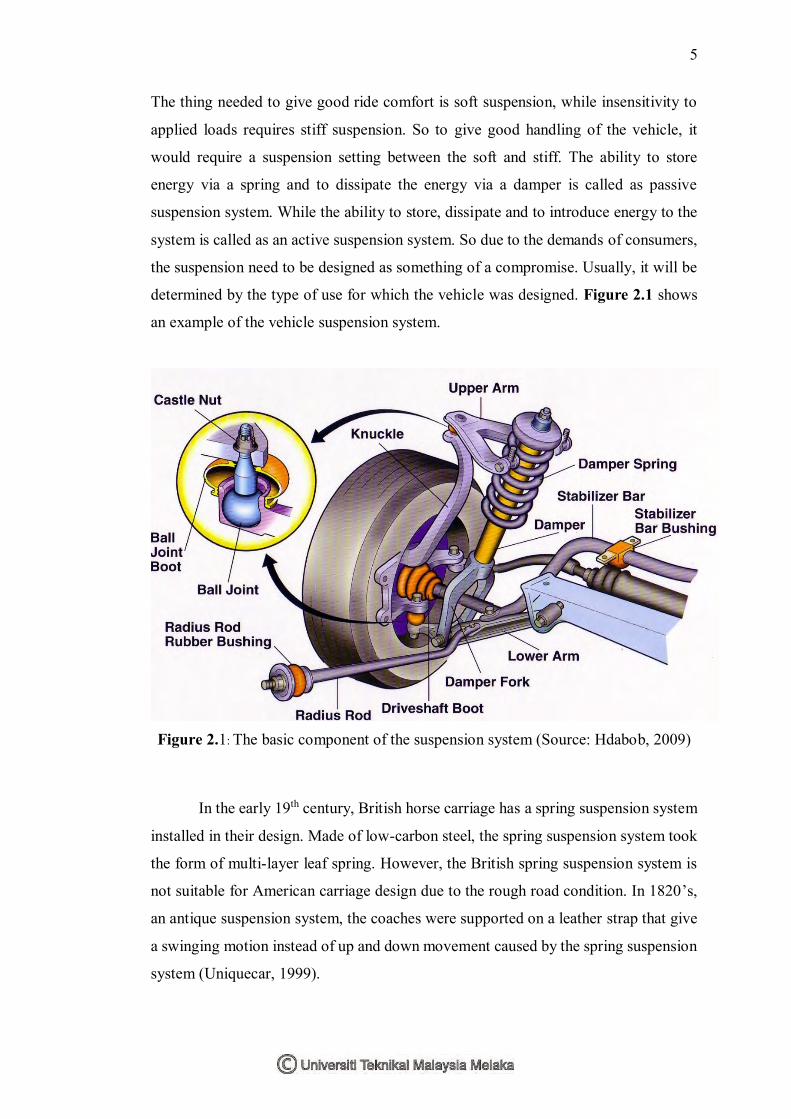
determined by the type of use for which the vehicle was designed. Figure 2.1 shows
an example of the vehicle suspension system.
Figure 2.1: The basic component of the suspension system (Source: Hdabob, 2009)
In the early 19th century, British horse carriage has a spring suspension system
installed in their design. Made of low-carbon steel, the spring suspension system took
the form of multi-layer leaf spring. However, the British spring suspension system is
not suitable for American carriage design due to the rough road condition. In 1820’s,
an antique suspension system, the coaches were supported on a leather strap that give
a swinging motion instead of up and down movement caused by the spring suspension
system (Uniquecar, 1999).
6
As the innovation of auto development, the steed drawn enhancing vehicles
into fueled by interior burning motor, the suspension framework utilized for the
carriage was esteemed out of date because of the distinction in velocity since the
suspension framework for the carriage is inadmissible for motor controlled vehicle.
The suspension framework was later modify by Mors of Paris in 1901, when the car
organization fitted a safeguard to their vehicle. Henri Fournier won the prestigious
Paris-to-Berlin race on the twentieth of June 1901 because of this change.
Torsion bar was presented as a component of the suspension framework in
1921 via Leyland Motors. In 1922, independent front suspension was utilized as part
of the outline of Lancia Lambda and get to be regular in mass business sector vehicle
since 1932.
2.1.2 Purpose of the Suspension System
The suspension system is located between the wheel axles and the vehicle body
or frame. The purpose of suspension system are to support the weight of the vehicle,
to maintain the traction between the tires and the road, cushion bumps and hole in the
road and hold the wheels in alignment.
The suspension system allows the vehicle to travel over rough surfaces with a
minimum of up and down body movement. Besides that, it will also allow the vehicle
to corner with minimum roll to lose the traction between the road surfaces and the
tires. This provides a cushioning action so road shocks have a minimal effect on the
occupants and load in the vehicle. Road shock is the result of action from tires moving
up and down as they meet bumps or holes in the road.
2.1.3 Component of Suspension System
The component of suspension system includes the spring and all the related
parts that support the weight of the vehicle body on the wheels and axles. The main
part of suspension system is the shock absorber and springs. The shock absorber will
help to control the spring action, while the spring will support the weight of the vehicle