Embed Size (px)
Citation preview
1
marleypd.co.uk
D E S I G N & I N S TA L L AT I O N G U I D E
HDPE Soil

I N N OVAT I O N & E X P E RT I S E
MARLEY HDPE |
HDPE Soil
Marley HDPE is a drainage system which offers an
alternative solution to cast iron. It is particularly suited for
commercial applications or where a product with high
impact or abrasion resistance is required, such as hospitals,
hotels, schools, as well as residential buildings. Marley
HDPE is certified to BS EN 1519. HDPE will also cope with
temperature variations of -40°C to 100°C * making it ideal
for external as well as internal installations.
*Applications possible between -40°C and 80°C. HDPE is suitable up to 100°C for short periods of time.
3
4 Range overview
6 Product specification
18 System overview
20 Material properties
22 Installation
23 HDPE jointing methods
32 Transitions to other materials
36 HDPE bracketry
50 Typical installations
52 Appendix
59 Case study
60 HDPE handling and storage
61 British and European standards
62 Technical services
Crayford, Kent
Contents
FM 30637 KM 545820EMS 96207BS EN 1519
54 MARLEY HDPE || MARLEY HDPE
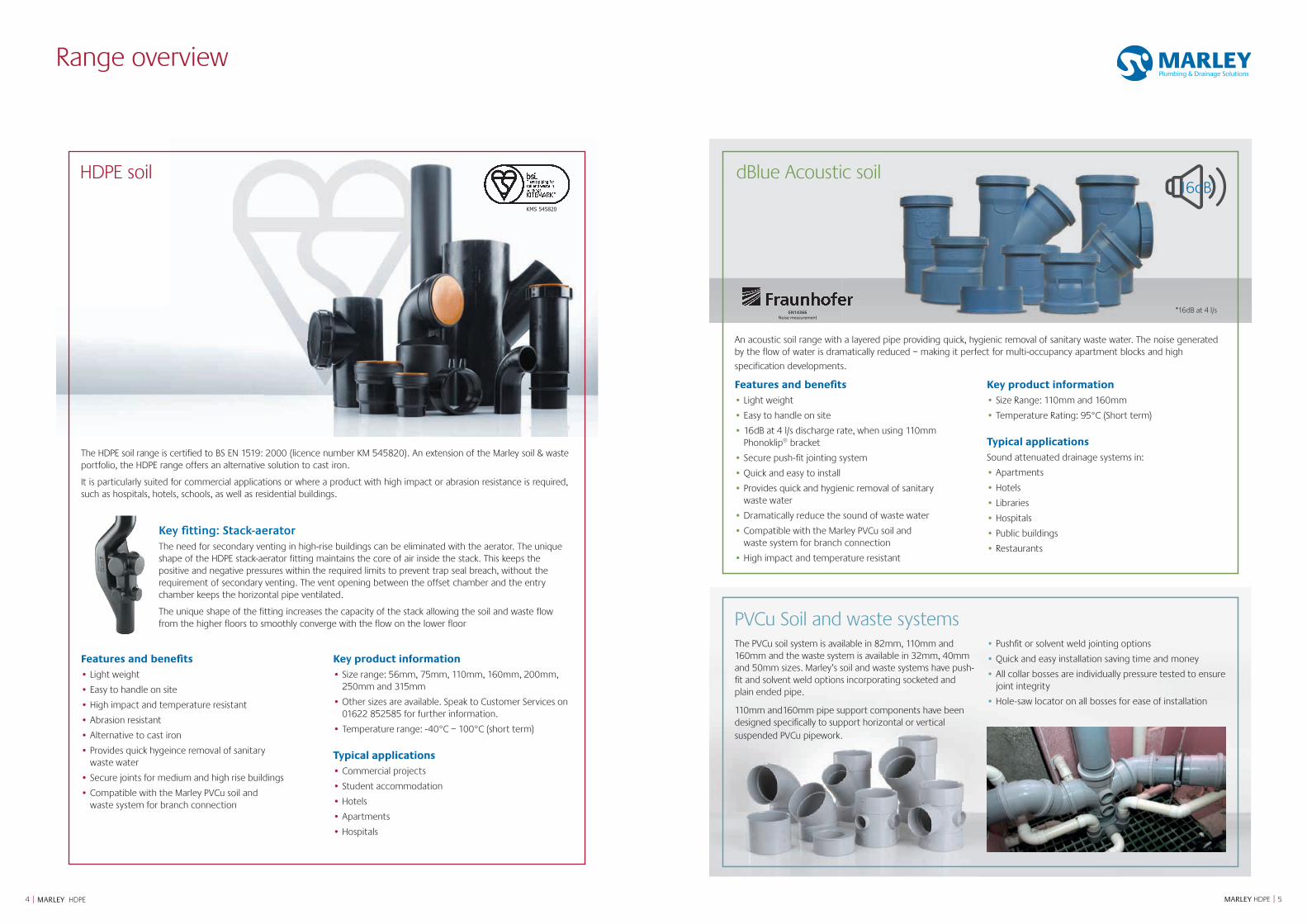
The HDPE soil range is certified to BS EN 1519: 2000 (licence number KM 545820). An extension of the Marley soil & waste portfolio, the HDPE range offers an alternative solution to cast iron.
It is particularly suited for commercial applications or where a product with high impact or abrasion resistance is required, such as hospitals, hotels, schools, as well as residential buildings.
Key fitting: Stack-aeratorThe need for secondary venting in high-rise buildings can be eliminated with the aerator. The unique shape of the HDPE stack-aerator fitting maintains the core of air inside the stack. This keeps the positive and negative pressures within the required limits to prevent trap seal breach, without the requirement of secondary venting. The vent opening between the offset chamber and the entry chamber keeps the horizontal pipe ventilated.
The unique shape of the fitting increases the capacity of the stack allowing the soil and waste flow from the higher floors to smoothly converge with the flow on the lower floor
Features and benefits• Light weight
• Easy to handle on site
• High impact and temperature resistant
• Abrasion resistant
• Alternative to cast iron
• Provides quick hygeince removal of sanitary waste water
• Secure joints for medium and high rise buildings
• Compatible with the Marley PVCu soil and waste system for branch connection
Key product information• Size range: 56mm, 75mm, 110mm, 160mm, 200mm,
250mm and 315mm
• Other sizes are available. Speak to Customer Services on 01622 852585 for further information.
• Temperature range: -40°C – 100°C (short term)
Typical applications• Commercial projects
• Student accommodation
• Hotels
• Apartments
• Hospitals
16dB*
EN14366Noise measurement
dBlue Acoustic soil
*16dB at 4 l/s
PVCu Soil and waste systemsThe PVCu soil system is available in 82mm, 110mm and 160mm and the waste system is available in 32mm, 40mm and 50mm sizes. Marley’s soil and waste systems have push-fit and solvent weld options incorporating socketed and plain ended pipe.
110mm and160mm pipe support components have been designed specifically to support horizontal or vertical suspended PVCu pipework.
• Pushfit or solvent weld jointing options
• Quick and easy installation saving time and money
• All collar bosses are individually pressure tested to ensure joint integrity
• Hole-saw locator on all bosses for ease of installation
An acoustic soil range with a layered pipe providing quick, hygienic removal of sanitary waste water. The noise generated by the flow of water is dramatically reduced – making it perfect for multi-occupancy apartment blocks and high
specification developments.
Features and benefits• Light weight
• Easy to handle on site
• 16dB at 4 l/s discharge rate, when using 110mm Phonoklip® bracket
• Secure push-fit jointing system
• Quick and easy to install
• Provides quick and hygienic removal of sanitary waste water
• Dramatically reduce the sound of waste water
• Compatible with the Marley PVCu soil and waste system for branch connection
• High impact and temperature resistant
Key product information• Size Range: 110mm and 160mm
• Temperature Rating: 95°C (Short term)
Typical applicationsSound attenuated drainage systems in:
• Apartments
• Hotels
• Libraries
• Hospitals
• Public buildings
• Restaurants
HDPE soil
Range overview
KMS 545820
Product Specifications
76 MARLEY HDPE || MARLEY HDPE
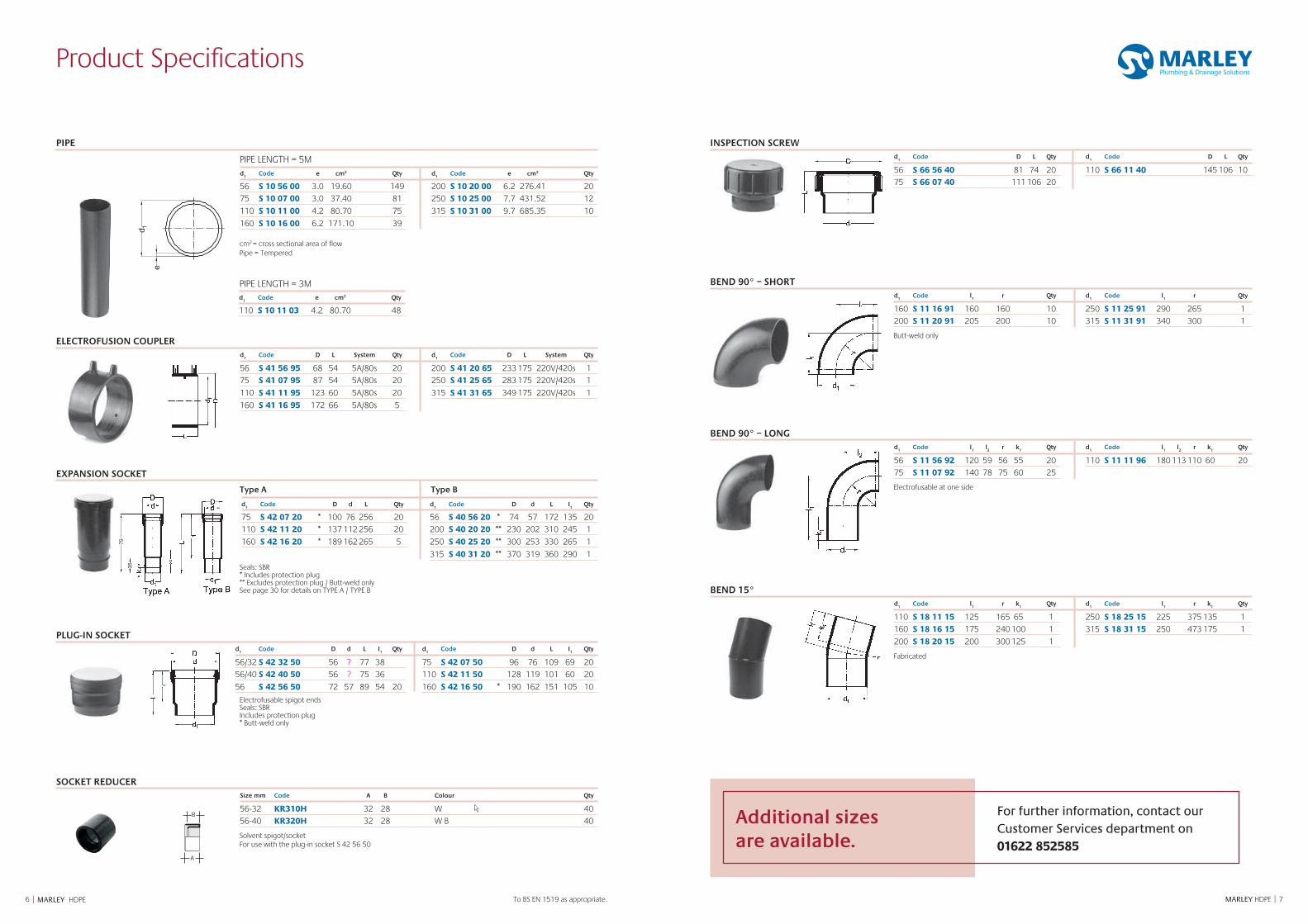
INSPECTION SCREWd
1Code D L Qty d
1Code D L Qty
56 S 66 56 40 81 74 20 110 S 66 11 40 145 106 10
75 S 66 07 40 111 106 20
BEND 90° – SHORT d
1Code l
1 r Qty d
1Code l
1 r Qty
160 S 11 16 91 160 160 10 250 S 11 25 91 290 265 1
200 S 11 20 91 205 200 10 315 S 11 31 91 340 300 1
Butt-weld only
BEND 90° – LONGd
1Code l
1l2
r k1 Qty d
1Code l
1l2
r k1 Qty
56 S 11 56 92 120 59 56 55 20 110 S 11 11 96 180 113 110 60 20
75 S 11 07 92 140 78 75 60 25
Electrofusable at one side
BEND 15° d
1Code l
1r k
1 Qty d
1Code l
1r k
1 Qty
110 S 18 11 15 125 165 65 1 250 S 18 25 15 225 375 135 1
160 S 18 16 15 175 240 100 1 315 S 18 31 15 250 473 175 1
200 S 18 20 15 200 300 125 1
Fabricated
PIPE
d1
Code e cm2 Qty d1
Code e cm2 Qty
56 S 10 56 00 3.0 19.60 149 200 S 10 20 00 6.2 276.41 20
75 S 10 07 00 3.0 37.40 81 250 S 10 25 00 7.7 431.52 12
110 S 10 11 00 4.2 80.70 75 315 S 10 31 00 9.7 685.35 10
160 S 10 16 00 6.2 171.10 39
cm2 = cross sectional area of flow Pipe = Tempered
ELECTROFUSION COUPLERd
1Code D L System Qty d
1Code D L System Qty
56 S 41 56 95 68 54 5A/80s 20 200 S 41 20 65 233 175 220V/420s 1
75 S 41 07 95 87 54 5A/80s 20 250 S 41 25 65 283 175 220V/420s 1
110 S 41 11 95 123 60 5A/80s 20 315 S 41 31 65 349 175 220V/420s 1
160 S 41 16 95 172 66 5A/80s 5
EXPANSION SOCKET
Type A Type B
d1
Code D d L Qty d1
Code D d L I1
Qty
75 S 42 07 20 * 100 76 256 20 56 S 40 56 20 * 74 57 172 135 20
110 S 42 11 20 * 137 112 256 20 200 S 40 20 20 ** 230 202 310 245 1
160 S 42 16 20 * 189 162 265 5 250 S 40 25 20 ** 300 253 330 265 1
315 S 40 31 20 ** 370 319 360 290 1
Seals: SBR * Includes protection plug ** Excludes protection plug / Butt-weld only See page 30 for details on TYPE A / TYPE B
PLUG-IN SOCKETd
1Code D d L I
1Qty d
1Code D d L I
1Qty
56/32 S 42 32 50 56 ? 77 38 75 S 42 07 50 96 76 109 69 20
56/40 S 42 40 50 56 ? 75 36 110 S 42 11 50 128 119 101 60 20
56 S 42 56 50 72 57 89 54 20 160 S 42 16 50 * 190 162 151 105 10
Electrofusable spigot ends Seals: SBR
Includes protection plug * Butt-weld only
SOCKET REDUCERSize mm Code A B Colour Qty
56-32 KR310H 32 28 W 40
56-40 KR320H 32 28 W B 40
Solvent spigot/socket For use with the plug-in socket S 42 56 50
PIPE LENGTH = 5M
PIPE LENGTH = 3M
3575
To BS EN 1519 as appropriate.
d1
Code e cm2 Qty
110 S 10 11 03 4.2 80.70 48
B
A
B
A
A
B C
A
BC
A
B
B
A
C
A
Additional sizes are available.
For further information, contact our Customer Services department on 01622 852585
Product Specifications
98 MARLEY HDPE || MARLEY HDPE
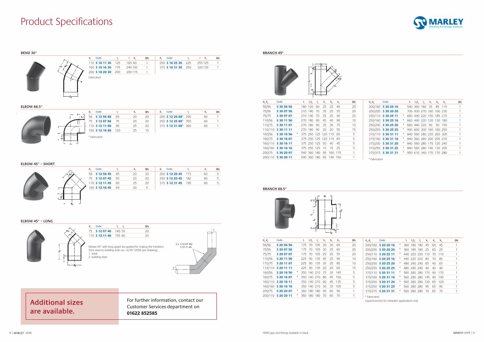
BEND 30° d
1Code l
1r k
1 Qty d
1Code l
1r k
1 Qty
110 S 18 11 30 125 165 60 1 250 S 18 25 30 225 255 125 1
160 S 18 16 30 175 240 100 1 315 S 18 31 30 250 320 135 1
200 S 18 20 30 200 200 115 1
Fabricated
ELBOW 88.5° d
1Code l
1k
1Qty d
1Code l
1k
1Qty
56 S 12 56 88 65 20 20 200 S 12 20 88* 290 60 1
75 S 12 07 88 75 20 20 250 S 12 25 88* 350 60 1
110 S 12 11 88 95 25 20 315 S 12 31 88* 360 60 1
160 S 12 16 88 120 25 10
* Fabricated
ELBOW 45° – SHORT d
1Code l
1k
1Qty d
1Code l
1k
1Qty
56 S 12 56 45 45 20 20 200 S 12 20 45 173 60 5
75 S 12 07 45 50 20 20 250 S 12 25 45 182 60 5
110 S 12 11 45 60 25 20 315 S 12 31 45 195 60 5
160 S 12 16 45 69 20 5
ELBOW 45° – LONGd
1Code l
1l2
Qty
75 S 12 07 46 145 50 20
110 S 12 11 46 155 60 20
Elbows 45° with long spigot are applied for making the transition from stack to building drain acc. to EN 12056 (see drawing). 1 stack 2 building drain
1
2
2 x S 12 07 46/ S 12 11 46
120
25
d1/
d2
Code L l1/l
2l3
k1
k2
k3
Qty
56/56 S 30 56 56 180 120 60 25 25 40 20
75/56 S 30 07 56 210 140 70 35 25 55 20
75/75 S 30 07 07 210 140 70 25 25 40 20
110/56 S 30 11 56 270 180 90 45 40 90 10
110/75 S 30 11 07 270 180 90 35 30 75 10
110/110 S 30 11 11 270 180 90 20 20 55 15
160/56 S 30 16 56 * 375 250 125 120 115 65 5
160/75 S 30 16 07 375 250 125 120 115 65 5
160/110 S 30 16 11 375 250 125 50 40 45 5
160/160 S 30 16 16 375 250 125 10 15 25 5
200/75 S 30 20 07 540 360 180 95 160 175 1
200/110 S 30 20 11 540 360 180 65 140 150 1
d1/
d2
Code L l1/l
2l3
k1
k2
k3
Qty
200/160 S 30 20 16 540 360 180 35 85 115 1
200/200 S 30 20 20 700 430 270 160 160 230 1
250/110 S 30 25 11 * 660 440 220 150 185 215 1
250/160 S 30 25 16 * 660 440 220 120 130 180 1
250/200 S 30 25 20 * 660 440 220 90 50 150 1
250/250 S 30 25 25 * 900 600 300 160 160 250 1
315/110 S 30 31 11 * 840 560 280 235 260 305 1
315/160 S 30 31 16 * 840 560 280 200 205 270 1
315/200 S 30 31 20 * 840 560 280 175 125 240 1
315/250 S 30 31 25 * 840 560 280 140 130 205 1
315/315 S 30 31 31 * 950 610 340 170 170 280 1
* Fabricated
BRANCH 45º
HDPE pipe and fittings available in black.
BRANCH 88.5°
d1/
d2
Code L l1/l
2l3
k1
k2
k3
Qty
56/56 S 20 56 56 175 70 105 30 30 65 20
75/56 S 20 07 56 175 70 105 30 25 65 20
75/75 S 20 07 07 175 70 105 25 25 55 20
110/56 S 20 11 56 225 90 135 45 25 90 10
110/75 S 20 11 07 225 90 135 35 25 85 10
110/110 S 20 11 11 225 90 135 20 20 65 15
160/56 S 20 16 56 * 350 140 210 75 30 145 5
160/75 S 20 16 07 * 350 140 210 80 45 150 5
160/110 S 20 16 11 350 140 210 60 45 135 5
160/160 S 20 16 16 350 140 210 30 35 105 5
200/75 S 20 20 07 * 360 180 180 90 60 90 1
200/110 S 20 20 11 * 360 180 180 70 60 70 1
d1/
d2
Code L l1/l
2l3
k1
k2
k3
Qty
200/160 S 20 20 16 * 360 180 180 45 60 45 1
200/200 S 20 20 20 * 360 180 180 25 60 25 1
250/110 S 20 25 11 * 440 220 220 110 70 110 1
250/160 S 20 25 16 * 440 220 220 85 70 85 1
250/200 S 20 25 20 * 480 240 240 65 40 65 1
250/250 S 20 25 25 * 480 240 240 40 40 40 1
315/110 S 20 31 11 * 560 280 280 170 90 170 1
315/160 S 20 31 16 * 560 280 280 145 90 145 1
315/200 S 20 31 20 * 560 280 280 120 65 120 1
315/250 S 20 31 25 * 560 280 280 95 65 95 1
315/315 S 20 31 31 * 560 280 280 70 65 70 1
* Fabricated
Equal branches for rainwater applications onlyAdditional sizes are available.
For further information, contact our Customer Services department on 01622 852585
Product Specifications
1110 MARLEY HDPE || MARLEY HDPE
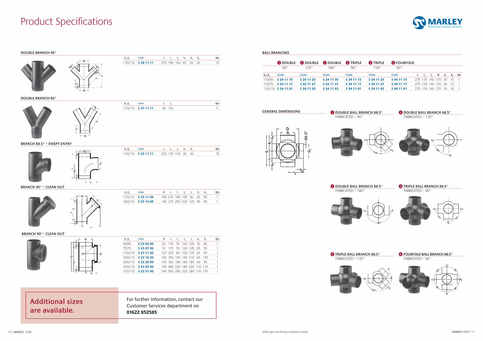
DOUBLE BRANCH 45°d
1/ d
2Code L l
1l2
k1 k
2k
3Qty
110/110 S 36 11 11 270 180 100 65 20 20 10
DOUBLE BRANCH 60°d
1/ d
2Code l
1 l
2 Qty
110/110 S 37 11 11 90 102 5
BRANCH 88.5° – SWEPT ENTRYd
1/ d
2Code L l
1 l
2 k
1 k
3Qty
110/110 S 25 11 11 225 135 130 30 30 15
BRANCH 45° – CLEAN OUTd
1/ d
2Code D L l
1 l
2 l
3 k
1 k
3 Qty
110/110 S 33 11 00 140 270 180 195 90 20 55 1
160/110 S 33 16 00 140 375 250 220 125 45 45 1
BRANCH 90°– CLEAN OUTd
1/ d
2Code D L l
1 l
2 l
3 k
1 k
3Qty
56/56 S 23 56 00 83 175 70 100 105 30 65 1
75/75 S 23 07 00 91 175 70 100 105 25 55 1
110/110 S 23 11 20 127 225 90 105 135 20 65 1
160/110 S 23 16 20 140 350 140 140 210 60 135 1
200/110 S 23 20 00 140 360 180 160 180 90 90 1
250/110 S 23 25 00 140 440 220 185 220 110 110 1
315/110 S 23 31 00 140 560 280 220 280 170 170 1
BALL BRANCHES
GENERAL DIMENSIONS 1 DOUBLE BALL BRANCH 88.5° FABRICATED – 90°
2 DOUBLE BALL BRANCH 88.5° FABRICATED – 135°
3 DOUBLE BALL BRANCH 88.5° FABRICATED – 180°
4 TRIPLE BALL BRANCH 88.5° FABRICATED – 90°
1 DOUBLE 90°
2 DOUBLE 135°
3 DOUBLE 180°
4 TRIPLE 90°
5 TRIPLE 135°
6 FOURFOLD 90°
d1/ d
2Code Code Code Code Code Code L l
1 l
2 D k
1 k
2 Qty
110/56 S 24 11 15 S 24 11 25 S 24 11 35 S 34 11 15 S 34 11 25 S 44 11 15 275 135 140 170 30 15 1
110/75 S 24 11 17 S 24 11 27 S 24 11 37 S 34 11 17 S 34 11 27 S 44 11 17 275 135 140 170 30 15 1
110/110 S 24 11 01 S 24 11 02 S 24 11 03 S 34 11 01 S 34 11 02 S 44 11 01 275 135 140 170 30 30 1
5 TRIPLE BALL BRANCH 88.5° FABRICATED – 135°
6 FOURFOLD BALL BRANCH 88.5° FABRICATED – 90°
HDPE pipe and fittings available in black.
Additional sizes are available.
For further information, contact our Customer Services department on 01622 852585
Product Specifications
1312 MARLEY HDPE || MARLEY HDPE
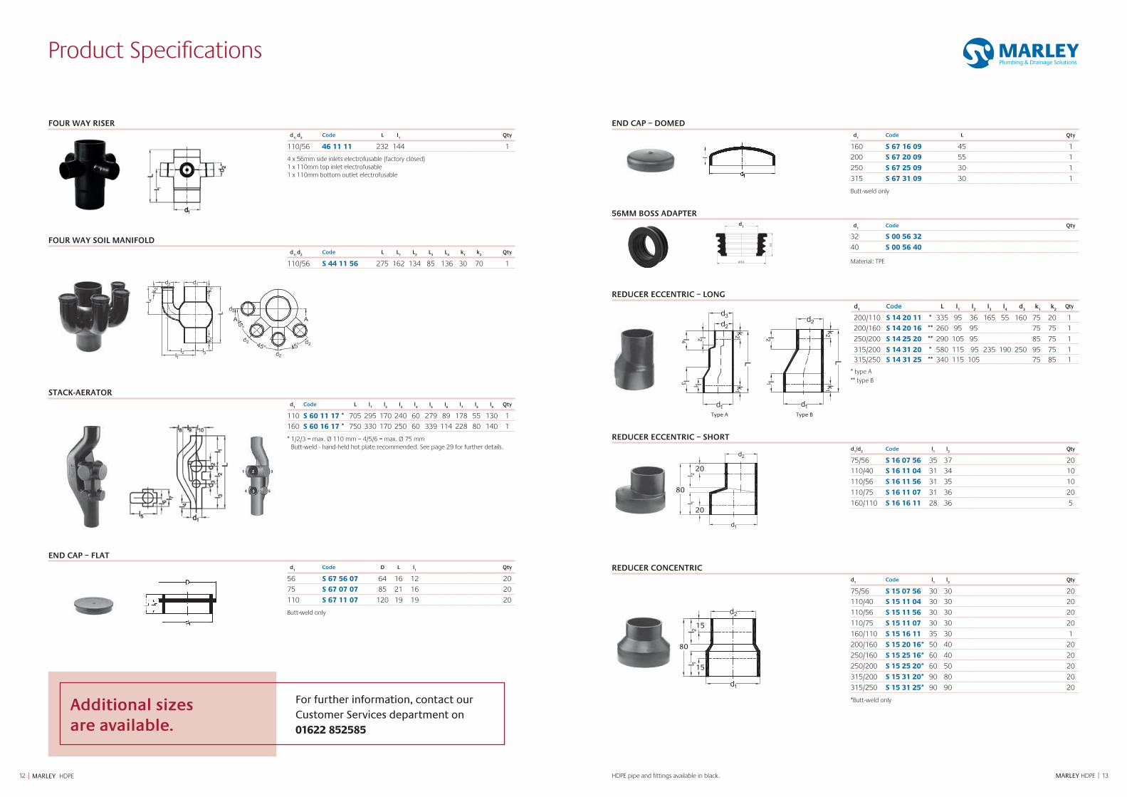
END CAP – DOMEDd
1Code L Qty
160 S 67 16 09 45 1
200 S 67 20 09 55 1
250 S 67 25 09 30 1
315 S 67 31 09 30 1
Butt-weld only
56MM BOSS ADAPTERd
1Code Qty
32 S 00 56 32
40 S 00 56 40
Material: TPE
REDUCER ECCENTRIC – LONGd
1Code L l
1 l
2l3
l4
d3
k1
k2
Qty
200/110 S 14 20 11 * 335 95 36 165 55 160 75 20 1
200/160 S 14 20 16 ** 260 95 95 75 75 1
250/200 S 14 25 20 ** 290 105 95 85 75 1
315/200 S 14 31 20 * 580 115 95 235 190 250 95 75 1315/250 S 14 31 25 ** 340 115 105 75 85 1
* type A ** type B
REDUCER ECCENTRIC – SHORTd
1/d
2Code l
1l2
Qty
75/56 S 16 07 56 35 37 20
110/40 S 16 11 04 31 34 10
110/56 S 16 11 56 31 35 10
110/75 S 16 11 07 31 36 20
160/110 S 16 16 11 28 36 5
REDUCER CONCENTRIC d
1Code l
1l2
Qty
75/56 S 15 07 56 30 30 20110/40 S 15 11 04 30 30 20
110/56 S 15 11 56 30 30 20
110/75 S 15 11 07 30 30 20
160/110 S 15 16 11 35 30 1
200/160 S 15 20 16* 50 40 20
250/160 S 15 25 16* 60 40 20
250/200 S 15 25 20* 60 50 20
315/200 S 15 31 20* 90 80 20
315/250 S 15 31 25* 90 90 20
*Butt-weld only
FOUR WAY RISERd
1/ d
2Code L I
1Qty
110/56 46 11 11 232 144 1
4 x 56mm side inlets electrofusable (factory closed) 1 x 110mm top inlet electrofusable 1 x 110mm bottom outlet electrofusable
FOUR WAY SOIL MANIFOLDd
1/ d
2Code L L
1L
2L
3L
4k
1k
2Qty
110/56 S 44 11 56 275 162 134 85 136 30 70 1
STACK-AERATORd
1Code L l
1 l
2 l
3 l
4l5
l6
l7
l8
l9
Qty
110 S 60 11 17 * 705 295 170 240 60 279 89 178 55 130 1
160 S 60 16 17 * 750 330 170 250 60 339 114 228 80 140 1
* 1/2/3 = max. Ø 110 mm – 4/5/6 = max. Ø 75 mm Butt-weld - hand-held hot plate recommended. See page 29 for further details.
END CAP – FLATd
1Code D L l
1 Qty
56 S 67 56 07 64 16 12 20
75 S 67 07 07 85 21 16 20
110 S 67 11 07 120 19 19 20
Butt-weld only
25
Ø 5 3
Ø 3 6d1
Type A Type B
80
15
15
80
20
20
HDPE pipe and fittings available in black.
Additional sizes are available.
For further information, contact our Customer Services department on 01622 852585
Product Specifications
1514 MARLEY HDPE || MARLEY HDPE
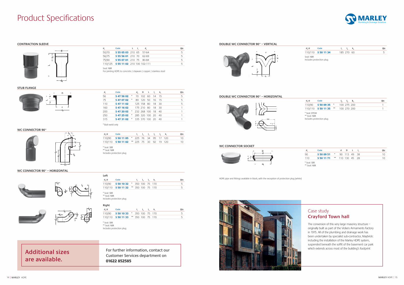
DOUBLE WC CONNECTOR 90° – VERTICALd
1/ d Code I
1I
2k
2Qty
110/110 S 50 11 34 185 270 60 5
Seal: NBR Includes protection plug
DOUBLE WC CONNECTOR 90° – HORIZONTALd
1/ d Code I
2I
3k
1Qty
110/90 S 50 09 35 * 100 275 200 1
110/110 S 50 11 35 ** 100 270 200 1
* Seal: EPDM ** Seal: NBR Includes protection plug
WC CONNECTOR SOCKETd
1Code d D L I
1Qty
90 S 50 09 51 * 90 113 49 38 10
110 S 50 11 71 ** 110 130 45 28 10
* Seal: SBR ** Seal: NBR
CONTRACTION SLEEVEd
1Code L I
1d
xQty
50/70 S 55 05 03 210 65 57-64 5
56/75 S 55 56 01 210 70 62-69 5
75/90 S 55 07 01 210 75 80-84 5
110/125 S 55 11 02 210 100 102-111 5
Seal: NBR For jointing HDPE to concrete / clayware / copper / stainless steel
STUB FLANGEd
1Code d
2 D L l
1 k
1 Qty
56 S 47 56 02 * 70 102 60 14 15 5
75 S 47 07 02 * 89 120 50 16 15 5
110 S 47 11 02 125 158 80 18 30 5
160 S 47 16 02 175 210 80 18 30 1
200 S 47 20 02 * 232 268 100 18 40 1
250 S 47 25 02 * 285 320 100 20 40 1
315 S 47 31 02 * 335 370 100 20 40 1 * Butt-weld only
WC CONNECTOR 90°d
1/ d Code l
1 l
2 l
3l4
l5 k
1Qty
110/90 S 50 11 85 * 225 76 34 95 17 120 10
110/110 S 50 11 82 ** 225 75 30 92 19 120 10 * Seal: SBR ** Seal: NBR Includes protection plug
WC CONNECTOR 90° – HORIZONTAL
Left
d1/ d Code I
1I
2I
3k
1Qty
110/90 S 50 10 32 * 350 100 75 170 5
110/110 S 50 11 32 ** 350 100 75 170 5 * Seal: SBR ** Seal: NBR Includes protection plug
Right
d1/ d Code I
1I
2I
3k
1Qty
110/90 S 50 10 33 * 350 100 75 170 5
110/110 S 50 11 33 ** 350 100 75 170 5 * Seal: SBR ** Seal: NBR Includes protection plug
360
HDPE pipe and fittings available in black, with the exception of protection plug (white)
Additional sizes are available.
For further information, contact our Customer Services department on 01622 852585
Case study Crayford Town hall
The conversion of this very large masonry structure – originally built as part of the Vickers Armaments Factory in 1915. All of the plumbing and drainage work has been undertaken by specialist sub-contractor, Maybrick: including the installation of the Marley HDPE system, suspended beneath the soffit of the basement car park which extends across most of the building’s footprint
Product Specifications
1716 MARLEY HDPE || MARLEY HDPE16 All documentation is available to download from marleypd.co.uk Technical hotline: 01622 852695
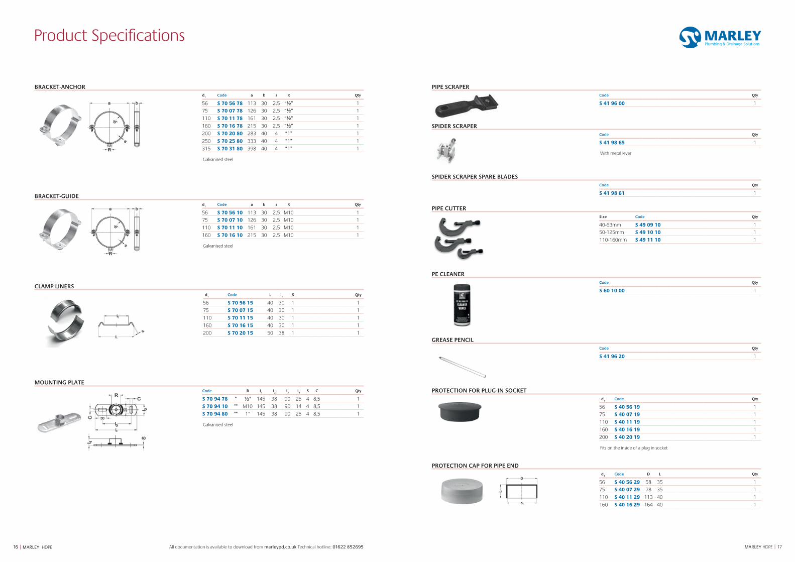
BRACKET-ANCHORd
1Code a b s R Qty
56 S 70 56 78 113 30 2.5 “½” 1
75 S 70 07 78 126 30 2.5 “½” 1
110 S 70 11 78 161 30 2.5 “½” 1
160 S 70 16 78 215 30 2.5 “½” 1
200 S 70 20 80 283 40 4 “1” 1
250 S 70 25 80 333 40 4 “1” 1
315 S 70 31 80 398 40 4 “1” 1
Galvanised steel
BRACKET-GUIDEd
1Code a b s R Qty
56 S 70 56 10 113 30 2.5 M10 1
75 S 70 07 10 126 30 2.5 M10 1
110 S 70 11 10 161 30 2.5 M10 1
160 S 70 16 10 215 30 2.5 M10 1
Galvanised steel
CLAMP LINERSd
1Code L l
1 S Qty
56 S 70 56 15 40 30 1 1
75 S 70 07 15 40 30 1 1
110 S 70 11 15 40 30 1 1
160 S 70 16 15 40 30 1 1
200 S 70 20 15 50 38 1 1
MOUNTING PLATECode R I
1I
2I
3I
4S C Qty
S 70 94 78 * ½” 145 38 90 25 4 8,5 1
S 70 94 10 ** M10 145 38 90 14 4 8,5 1
S 70 94 80 ** 1” 145 38 90 25 4 8,5 1
Galvanised steel
PIPE SCRAPERCode Qty
S 41 96 00 1
SPIDER SCRAPERCode Qty
S 41 98 65 1
With metal lever
SPIDER SCRAPER SPARE BLADESCode Qty
S 41 98 61 1
PIPE CUTTERSize Code Qty
40-63mm S 49 09 10 1
50-125mm S 49 10 10 1
110-160mm S 49 11 10 1
PE CLEANERCode Qty
S 60 10 00 1
GREASE PENCILCode Qty
S 41 96 20 1
PROTECTION FOR PLUG-IN SOCKETd
1Code Qty
56 S 40 56 19 1
75 S 40 07 19 1
110 S 40 11 19 1
160 S 40 16 19 1
200 S 40 20 19 1
Fits on the inside of a plug in socket
PROTECTION CAP FOR PIPE ENDd
1Code D L Qty
56 S 40 56 29 58 35 1
75 S 40 07 29 78 35 1
110 S 40 11 29 113 40 1
160 S 40 16 29 164 40 1
1918 MARLEY HDPE || MARLEY HDPE
System Overview
HDPE Soil is a durable and tough drainage system, designed to be installed in
accordance with EN12056 ‘Gravity drainage systems inside buildings’.
The excellent characteristics of high density polyethylene (HDPE) makes it suitable for a
wide range of applications. HDPE is available in various pipe sizes, with a comprehensive
range of fittings including connection fittings, sanitary fittings and tools.
The system has the following features:
• Complete system with excellent mechanical and chemical resistance properties
• Manufactured from polyethylene: a proven material that is tough, elastic and flexible
• HDPE pipe is tempered for reduced stress on connections
• Homogenous welded joints offer a completely closed system
• A wide range of mechanical joints for adjustability, flexibility and demounting
• Additives makes HDPE UV and weather resistant
• HDPE is highly suited for prefabrication
• Non-toxic plastic, 100% recyclable and environmentally friendly
• Stack-aerator is the perfect high-rise solution
Applications
HDPE is designed to be installed in accordance with EN 12056 and thereby meets the requirements for use in residential, commercial and public buildings.
HDPE is a non-pressure drainage system, not intended for pressure applications.
HDPE has a high temperature and chemical resistance which makes it ideal for drainage in:
• Student accommodation
• Apartments
• Commercial projects
It is flexible and tough for installation:
• Underground
• Embedded in concrete
Its closed system is perfect for applications where system integrity connections are critical like in:
• Industrial applications
• Ceiling voids and hard to reach places
Furthermore HDPE is a light weight system, highly suited for prefabrication. It allows you to meet the challenges of modern
building design.
Application parameters
The pipes, fittings and seals can be used continuously at elevated temperature.
For a complete overview refer to the appendix on page 52. HDPE is suitable for the drainage of chemically aggressive waste water with a pH value of 2 (acidic) to 12 (basic) by default. For installations in applications not listed in this brochure or with chemicals not listed in the chemical resistance list of this brochure, please contact Technical Services on 01622 852695
Behaviour in fire corresponds to B2 normal combustibility according to DIN 4102. When a HDPE pipe system passes through fire-rated building elements, it is mandatory to install fire protection collars that will not reduce the fire-rating of these building elements.
Linear expansion
Marley HDPE material has a linear expansion coefficient of 0.18 mm/mK. We calculate with an expansion of 0.2mm per meter pipe for every °C temperature difference. The total length variation can be calculated as follows:
Δl = L x λ x Δt
Δl = length change in mm
L = total length of pipe
λ = linear expansion coefficient
Δt = temperature difference in °C
Example:
10 metres of pipe with a maximum temperature of 60°C and a minimum temperature of -20°C. This results in an expansion of:
Δl = 10 x 0,2 x 80 = 160 mm
Length changes can be accommodated by the expansion socket which can take up the expansion and contraction of a 5 meter length of pipe for temperatures between -20°C and 70°C.
Abbreviations
Abbreviation
D External dimension fitting part
d1, d2 ... External dimension fitting/pipe
e Wall thickness
k1,k2 ... Maximum length for shortening fittings
L Total length fitting
l1,l2 ... Lengths of part of fitting
TPE Thermoplastic Elastomer
SBR Styrol butadiene rubber
NBR Acrylnitril-butadiene rubber
HDPE High density polethylene
SDRRatio diameter / wall thickness d
1/e
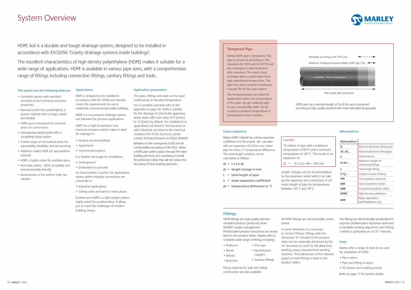
Shrinkage according to EN 1519 (3%)
Maximum shrinkage tempered Marley HDPE pipe (1%)
Pipe length after production
HDPE pipe has a standard length of 3m & 5m and is produced according to high quality standard with many international approvals.
Tempered Pipe
Marley HDPE pipe is tempered. This pipe is produced according to the standards EN 1519 and ISO 8770 and has undergone a heat treatment after extrusion. The result is less shrinkage when cooled down from high operational temperature. This gives less stress on joints resulting in a longer life for the pipe system.
The tempered pipes are suited for applications where the temperature of the pipe can get relatively high or vary considerably. Both can be caused by ambient temperature or temperature of the medium.
Fittings HDPE fittings are high quality injection moulded products produced under ISO9001 quality management. Prefabricated product exceptions are clearly listed in the product tables. Marley offers a complete wide range of fittings including:
• Reducers
• Bends
• Elbows
• Branches
• End caps
• Electrofusion couplers
• Sanitary fittings
Fixing materials for wall and ceiling construction are also available.
All HDPE fittings are electrofusable, unless stated
In some situations, it is necessary to shorten fittings. Fittings with the dimension “k” included in the product table can be maximally shortened by the “k” dimension in order to still allow butt-welding using a standard butt-welding machine. The k-dimension of the relevant spigot of most fittings is listed in the product tables.
The fittings are dimensionally standardised to improve prefabrication repetition work and to facilitate welding alignment. Each fitting contains a graduated arc at 15° intervals.
Tools
Marley offer a range of tools to be used for installation of HDPE:
• Pipe cutters
• Pipe and fitting scrapers
• PE cleaner and marking pencils
Refer to page 17 for further details.
2120 MARLEY HDPE || MARLEY HDPE
Material Properties
HDPE properties
Polyethylene (PE), is a semi crystalline thermoplastic and is a generic term for different kinds of PE. By colouring with 2% of ‘carbon black’ the PE gets its black colour. The following kinds of PE are generally used:
● LDPE (Density 0.90-0.91 g/cm3)
● MDPE (Density 0.93-0.94 g/cm3)
● HDPE (Density 0.94-0.97 g/cm3)
In pipe systems generally only HDPE is used. HDPE has a high resistance against acids, bases and aqueous salt-solutions. Below 60°C it is practically unsolvable in organic solutions. HDPE has a good resistance against light ionised radiation without becoming radioactive itself.
Technical specificationsUnit Test method Value
Density at 23°C g/cm³ ISO 1183 0.954
Elasticity modulus N/mm² ISO 527 850
Bending creep modulus N/mm² DIN 54852-Z4 1000
Tensile strength at 23°C N/mm² ISO 527 22
Elongation at break % ISO R 527 300
Linear expansion coefficient mm/mK DIN 53752 0.18
Indentation hardness N/mm² ISO 2039 36 - 46
Ignition temperature °C - ~350
Thermal conductivity W/m . K DIN 52612 0.37 - 0.43
Shore hardness ISO 868 61
Crystallite melting range °C 125 - 131
Operational temperature range °C - -40 - +80*
Melt Flow Rate MFR 190/5 g/10 min ISO 1133 0.43
* up to 100°C for short periods of time.
Ecological properties of HDPE
Polyethylene consists of only carbon and hydrogen atoms. These substances are not harmful to humans, animals and plants. Marley uses High Density Polyethylene classified with recycle mark 3.
Polyethylene is made from oil and electricity without chemical additives released during production. It is not broken down by bacteria very fast and has a long lifetime. The total energy consumption during production and transport is very low compared to steel, copper or cast iron.
Because PE is a thermoplastic polymer it can be melted at the end of its technical lifetime and used for other applications. When PE is burnt, only non-toxic carbon dioxide and water is released.
Chemical resistance
When transporting chemical waste waters the following factors have to be taken into account:
● The medium
● The concentration of this medium
● Temperature
● Duration of exposure
● Volume
Refer to appendix A for a complete chemical resistance table of Marley HDPE on page 52.
Trace heating
Animal and vegetable-based oil and grease discharged by commercial kitchens are separated from the waste water by grease separators. HDPE is very well suited to connect the discharge fixtures to the grease separator. When the pipe system has enough length, the grease can accumulate and lead to serious blockage of the pipe system. The use of trace heating and additional insulation may be required to reduce heat loss. The trace heating element should not exceed 45°C.
Embedding HDPE in concrete
The HDPE system is suited to be embedded in concrete. Before pouring the concrete all welds need to be cooled down and it is preferable to check the pipe system for leakage. To prevent the pipes from floating upwards the systems needs to be properly bracketed to keep it in place.
Diameter Wall thickness Allowed height (m) (mm) (mm)
Empty Filled with water
40 3.0 26.0 45.0
50 3.0 14.0 24.0
56 3.0 7.0 12.0
63 3.0 7.0 12.0
75 3.0 3.8 6.5
90 3.5 3.8 6.5
110 4.2 3.8 6.5
125 4.8 3.8 6.5
160 6.2 3.8 6.5
200 6.2 2.0 3.5
250 7.7 2.0 3.5
315 9.7 2.0 3.5
200 7.7 3.8 6.5
250 9.6 3.8 6.5
315 12.1 3.8 6.5
Pressure and heat during concrete pouring
When a pipe system is vertically installed into concrete the liquid concrete will cause outer pressure, possibly exceeding the maximum ring stiffness depending on the height of the installation.
To increase the maximum installation height the pipe can be filled with water (and closed) to compensate for the outer pressure. Refer to the table opposite for the maximum allowed height depending also on the wall thickness of the pipes and fittings (at 30°C).
Quick drying concrete
Quick drying concrete will undergo an exothermic reaction which releases heat during its process. The heat will soften the HDPE pipe and influence the maximum allowed pressure. Adequate protection must be provided to the HDPE system like filling the system with water. For further information on embedding HDPE in concrete see page 43.
In residential applications the maximum wall temperature difference of the connector and collector pipes is 40°C, even during short periods of 80°C to 90°C temperature water discharge.
For downpipes and ground pipes the maximum wall temperature difference is 20°C.
In general for a long-lasting discharge of high volume hot water the maximum wall temperature difference is 60°C.
Please note that this is the temperature difference over the complete circumference of the pipe, the variation in the discharge temperature can be a lot higher.
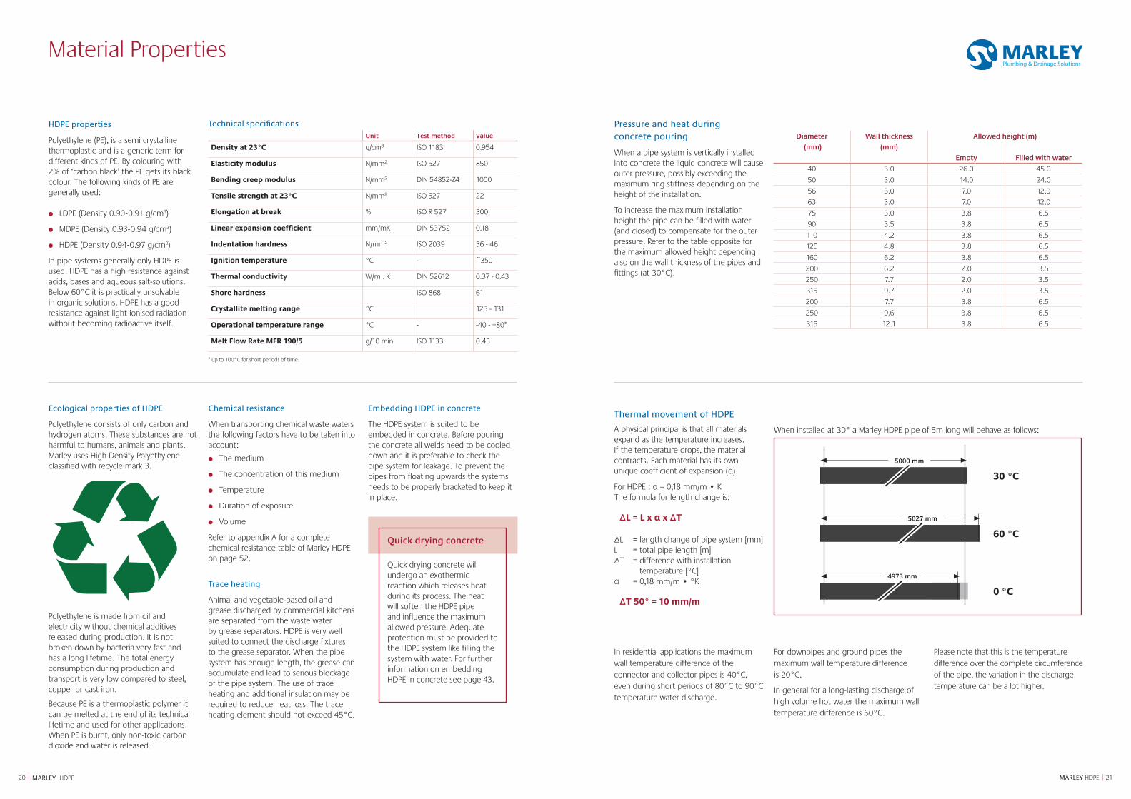
5000 mm
5027 mm
4973 mm
30 °C
60 °C
0 °C
Thermal movement of HDPE
A physical principal is that all materials expand as the temperature increases. If the temperature drops, the material contracts. Each material has its own unique coefficient of expansion (α).
For HDPE : α = 0,18 mm/m • KThe formula for length change is:
ΔL = L x α x ΔT
ΔL = length change of pipe system [mm]L = total pipe length [m]ΔT = difference with installation
temperature [°C]α = 0,18 mm/m • °K
ΔT 50° = 10 mm/m
When installed at 30° a Marley HDPE pipe of 5m long will behave as follows:

2322 MARLEY HDPE || MARLEY HDPE
Installation
Jointing technique Product Welded/mechanical Pull-tight DemountableElectrofusion Welded Yes No
Butt-weld joint Welded Yes No
Plug-in Socket Mechanical No Yes
Expansion Socket Mechanical No Yes
Snap Socket * Mechanical Yes No
Screw Coupler * Mechanical Yes Yes
Flanges * Mechanical Yes Yes
Contraction Joint * Mechanical No No
* Available on request
HDPE fittings and pipes can be joined by different methods. Joints are divided in
welded/mechanical and pull-tight/not pull-tight. Pull-tight joints can’t come apart
under influence of external forces.
To be opened (demountable)These are jointing methods which can be disconnected after assembly. These jointing methods are ideal for pipe sections which need to be cleaned, calibrated, inspected or dismantled on a regular basis.
Not to be opened (fixed)These are jointing methods which cannot be disconnected after assembly. These are permanent joints in which the joints can remain closed for their lifetime.
Tension-resistant (pull tight: PT)These are connections which withstand tensional forces. This is ideal when thermal movement is expected or gravity pulls on the connection.
Non-tension-resistant (not pull tight: NPT)These are connections which cannot withstand tensional forces. This joint is used when the pipe system is designed to accommodate movement without risk that the joint is pulled apart.
HDPE jointing methods
Installation underground
Due to specific properties such as flexibility and resistance to cold temperature (freezing), HDPE pipe systems are ideal for use in underground pipe lines. Buried pipes are exposed to various loads. The stability of HDPE makes it possible to bury the pipes at substantial depth. The suitability depends on such factors as depth, groundwater level, density of the soil and traffic load. For further information on installing HDPE underground see page 44.
Soil and traffic loads
The load capacity of underground plastic pipes is based on changes in the pipe and movement of the ground. The soil load causes the top of the pipe to deflect downward. The sides of pipe are correspondingly pressed outward against the surrounding soil. The reaction pressure, the lateral force exercised on the pipe, prevents a larger cross-sectional deformation (support function). The construction of the trench, the type of bedding used and the backfilling of the trench are, to a large extent, decisive factors determining the load capacity of an underground plastic pipe. The load needs to be evenly distributed over the entire pipe line. For this reason, the trench must be created in such a manner that bends in a longitudinal direction and loads at specific points are avoided. It is assumed that the increased pressure resulting from traffic loads caused by road or rail traffic are surface evenly distributed over the pipe sectional plane.
Groundwater
Underground pipes can be subject to external overpressure, especially in areas with high groundwater levels. In addition, a pipe enclosed in concrete is exposed to external pressure, though just for a short period. Underground pipe systems subject to additional external pressure must be tested for the ability to withstand dinting. The effective load due to external pressure will agree with the related hydrostatic pressure on the pipe axis.
For special circumstances contact our Technical Service department on 01622 852695.

2524 MARLEY HDPE || MARLEY HDPE
Incorrect Jointing procedure
1. Misalignment
2. Coupler sliding when installed vertical
3. Welding more than once 4. Load on vertical pipe
10 mm
10 mm
10 mm
Correct Jointing procedure
1. Cut the pipe square
The pipe ends must be cut square to ensure that the heating element in the coupler is completely covered by the pipe or fitting.
2. Mark insertion depth + 10 mm
This is to ensure that across the full welding zone the oxidised layer will be removed.
3. Scrape pipe and mark insertion depth again
The outer surface of the pipe (approx. 0.2mm deep) must be scraped for the full distance that will be covered by the coupler to remove any surface 'oxidation'.
The insertion depth should be marked again to safeguard full insertion.
4. Clean coupler
Before assembling the pipes into the coupler ensure that all surfaces are clean and dry.
5. Insert pipe and/or fitting up to pipe stop
Ensure that the pipe is pushed as straight as possible into the fitting.
Electrofusion couplers
Couplers are extremely suitable for applications in wastewater and rainwater drainage, with the following features:
1. Injection moulded with excellent dimensional accuracy and stability.
2. Welding indicators on each welding surface for visual identification to show that the coupler has been welded.
3. Centre stops are easy to remove, in order to use the coupler as a slip coupler.
4. Resistance wires fixed to the surface for an optimal heat transfer and therefore a high quality welding connection.
5. Yellow edge surrounding the welding indicators of the diameters 200, 250 and 315mm are provided for better visibility.
The resistance wires are positioned in the fusion zone. On both sides of a fusion zone, a cold zone prevents the molten HDPE from outpouring thereby containing the fusion process.
During the fusion process the pipe/fitting expands and touches the inner coupler wall. The electrofusion joint is made with the pressure caused by the expanding HDPE and the heat from the resistance wires.
Electrofusion coupler with fusion and cold zones
Preparations
The following guidelines are of importance when making an accurate electrofusion joint:
• Establish a work space where the welding can be done without being effected by major weather conditions. Temperature -10°C/+40°C.
• Check if the equipment functions properly. Welding equipment used on site deserves special attention.
• The resistance wire in the electrofusion coupler lies at the surface for a good heat exchange. The resistance wires need to be covered by the inserted pipe or fitting to ensure correct operation.
• Complete insertion is essential to utilise the fusion and cold zones in the coupler.
• Make sure both ends inserted into the coupler have been properly scraped and have been cleaned. Both pipes and fittings need removal of the oxidation layer.
HDPE jointing methods
10 mm
cold zone fusion zone
ElectrofusionElectrofusion is a rapid and simple way of permanent jointing. Using the electrofusion couplers and equipment, pipes, fittings and prefabricated pipe sections can efficiently be assembled. All HDPE products can be welded by electrofusion unless specifically stated in the product table, see pages 6-17.
Welding process After connecting the cables of the control box the welding process can commence by pushing the start button. The control box adapts the welding time to the ambi-ent temperature. When it is colder than 20°C the welding time is extended and when the ambient temperature exceeds 20°C the welding time is shortened. For welding times and cooling down times see table below.
dimension d
1
systemweld time
cooling time
mm sec min
40-160Constant
current 5A80 20
200-315Constant
voltage 220V
420 30
The joint assembly should not be disturbed during the fusion cycle and for the specified cooling time afterwards. A full load can only be applied after the complete cooling time. The cooling period can be reduced by 50% when there is no additional load or strain during cooling.
welding indicators
200 – 315 mm 40 – 160 mm Compared to a butt-weld, it is harder to judge a good electrofusion weld. The welding indicators on the electrofusion coupler provide an indication if the weld has actually been executed. However, they do not guarantee the integrity of the joint. The amount of movement of the pop-out depends on several factors including the size tolerances of the components and any ovality of the pipe or fitting.
A joint can be marked o.k. when the welding indicators are protuded, all welding preparations such as marking insertion depth, scraping making sure that there was no additional load during welding and cooling have been executed successfully. If a significant quantity of melt flows out from the fitting after welding, there may be a misalignment of the components, the tolerances may be excessive or a second welding may have
accidentally occurred. The integrity of such a joint is suspicious.
Please note that the fitting will become too hot to be touched during the welding process. The temperature will continue to increase for some time after the fusion process has been completed.
Deformation
A big deformation of pipe and fitting can cause problems during assembly and welding of the components. The maximum allowed deformation of pipe or fitting spigot is 0.02 x d1. This results in a maximum difference between the largest and smallest diameter corresponding with the table below. The pipe or fitting spigot needs to be “rounded” using clamps when the deformation is larger.
diameter d1
d1 max - d
1 min
(mm) 40 1.050 1.056 1.063 1.075 1.590 2.0110 2.0125 2.5160 3.0200 4.0250 5.0315 6.0
42
KG
2x
42
KG
2x
42
KG
2x
42
KG
2x
10 mm
10 mm
10 mm
Without removing the oxygen layer a weld cannot be guaranteed.
2726 MARLEY HDPE || MARLEY HDPE
Preparations
The following guidelines are of importance when making an accurate butt-weld:
● Establish a work space where the jointing can be done without being effected by major weather conditions.
● Check the equipment functions properly. Welding equipment used on site deserves special attention.
● The fittings and or pipes need to be aligned in the welding machine. Mis-alignment can be up to 10% of the wall thickness.
● Clean the heating element before each jointing operation with a lint-free cloth and suitable cleaner (see instructions supplied with the welding machine).
● Cut the pipe and/or fitting with a pipe cutter to make the end square.
● Make sure that once the pipe and/or fitting ends have been machined, they do not get dirty. Do not touch them with your hands. The surface needs to be clear of oil, grease and dirt.
● Put the pipe parts into the welding machine to facilitate a firm hold during the jointing process.
● A digital thermometer can be used to check the temperature of the heating plate. The temperature should be checked at several points around the plate and should be between 200ºC and 220ºC. Maximum deviation between points is given in the table.
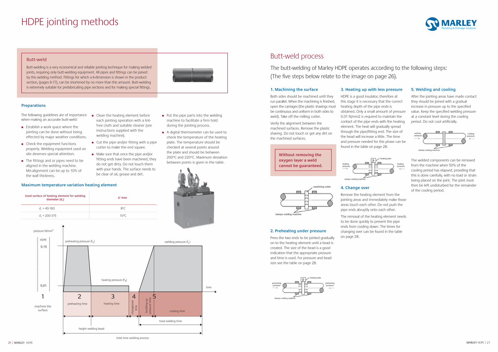
Butt-weld process
The butt-welding of Marley HDPE operates according to the following steps:
(The five steps below relate to the image on page 26).
1. Machining the surface
Both sides should be machined until they run parallel. When the machining is finished, open the carriages (the plastic shavings must be continuous and uniform in both sides to weld). Take off the milling cutter.
Verify the alignment between the machined surfaces. Remove the plastic shaving. Do not touch or get any dirt on the machined surfaces.
Without removing the oxygen layer a weld cannot be guaranteed.
2. Preheating under pressure
Press the two ends to be jointed gradually on to the heating element until a bead is created. The size of the bead is a good indication that the appropriate pressure and time is used. For pressure and bead size see the table on page 28.
3. Heating up with less pressure
HDPE is a good insulator, therefore at this stage it is necessary that the correct heating depth of the pipe ends is obtained. Only a small amount of pressure 0.01 N/mm2 is required to maintain the contact of the pipe ends with the heating element. The heat will gradually spread through the pipe/fitting end. The size of the bead will increase a little. The time and pressure needed for this phase can be found in the table on page 28.
4. Change over
Remove the heating element from the jointing areas and immediately make those areas touch each other. Do not push the pipe ends abruptly onto each other.
The removal of the heating element needs to be done quickly to prevent the pipe ends from cooling down. The times for changing over can be found in the table on page 28.
5. Welding and cooling
After the jointing areas have made contact they should be joined with a gradual increase in pressure up to the specified value. Keep the specified welding pressure at a constant level during the cooling period. Do not cool artificially.
The welded components can be removed from the machine when 50% of the cooling period has elapsed, providing that this is done carefully, with no load or strain being placed on the joint. The joint must then be left undisturbed for the remainder of the cooling period.
HDPE jointing methods
Butt-weld
Butt-welding is a very economical and reliable jointing technique for making welded joints, requiring only butt-welding equipment. All pipes and fittings can be joined by this welding method. Fittings for which a k-dimension is shown in the product section, (pages 6-17), can be shortened by no more than this amount. Butt-welding is extremely suitable for prefabricating pipe sections and for making special fittings.
(PE)
0,15
0,01
preheating pressure (Fo)
pressure N/mm2
heating pressure (Fd)
welding pressure (FL)
preheating time heating time
total time welding process
cooling time
total welding time
time
build
ing-
uppr
essu
re t
ime
chan
geov
ertim
e
height welding bead
HDPE
1 2 3 54
machine the surface
Maximum temperature variation heating element
Used surface of heating element for welding diameter (d
1)
Δt max
d1 = 40-160 8ºC
d1 = 200-315 10ºC
2928 MARLEY HDPE || MARLEY HDPE
HDPE jointing methods
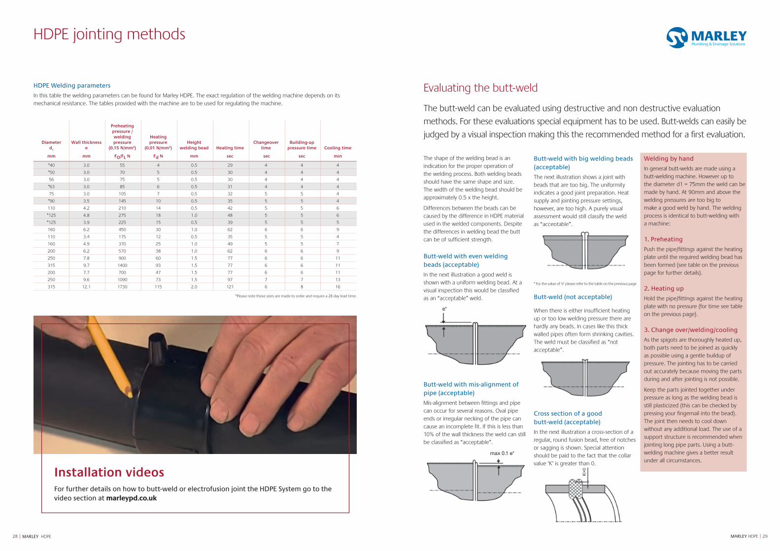
HDPE Welding parameters
In this table the welding parameters can be found for Marley HDPE. The exact regulation of the welding machine depends on its mechanical resistance. The tables provided with the machine are to be used for regulating the machine.
Diameter d
1
Wall thickness e
Preheating pressure / welding pressure
(0,15 N/mm2)
Heating pressure
(0,01 N/mm2)Height
welding bead Heating timeChangeover
timeBuilding-up
pressure time Cooling time
mm mm FO/FL N Fd N mm sec sec sec min
*40 3.0 55 4 0.5 29 4 4 4
*50 3.0 70 5 0.5 30 4 4 4
56 3.0 75 5 0.5 30 4 4 4
*63 3.0 85 6 0.5 31 4 4 4
75 3.0 105 7 0.5 32 5 5 4
*90 3.5 145 10 0.5 35 5 5 4
110 4.2 210 14 0.5 42 5 5 6
*125 4.8 275 18 1.0 48 5 5 6
*125 3.9 225 15 0.5 39 5 5 5
160 6.2 450 30 1.0 62 6 6 9
110 3.4 175 12 0.5 35 5 5 4
160 4.9 370 25 1.0 49 5 5 7
200 6.2 570 38 1.0 62 6 6 9
250 7.8 900 60 1.5 77 6 6 11
315 9.7 1400 93 1.5 77 6 6 11
200 7.7 700 47 1.5 77 6 6 11
250 9.6 1090 73 1.5 97 7 7 13
315 12.1 1730 115 2.0 121 6 8 16
*Please note these sizes are made to order and require a 28 day lead time.
Evaluating the butt-weld
The butt-weld can be evaluated using destructive and non destructive evaluation
methods. For these evaluations special equipment has to be used. Butt-welds can easily be
judged by a visual inspection making this the recommended method for a first evaluation.
The shape of the welding bead is an indication for the proper operation of the welding process. Both welding beads should have the same shape and size. The width of the welding bead should be approximately 0.5 x the height.
Differences between the beads can be caused by the difference in HDPE material used in the welded components. Despite the differences in welding bead the butt can be of sufficient strength.
�Butt-weld with even welding beads (acceptable)
In the next illustration a good weld is shown with a uniform welding bead. At a visual inspection this would be classified as an “acceptable” weld.
e*
Butt-weld with mis-alignment of pipe (acceptable)
Mis-alignment between fittings and pipe can occur for several reasons. Oval pipe ends or irregular necking of the pipe can cause an incomplete fit. If this is less than 10% of the wall thickness the weld can still be classified as “acceptable”.
max 0.1 e*
Butt-weld with big welding beads (acceptable)
The next illustration shows a joint with beads that are too big. The uniformity indicates a good joint preparation. Heat supply and jointing pressure settings, however, are too high. A purely visual assessment would still classify the weld as “acceptable”.
* For the value of ‘e’ please refer to the table on the previous page
Butt-weld (not acceptable)
When there is either insufficient heating up or too low welding pressure there are hardly any beads. In cases like this thick walled pipes often form shrinking cavities. The weld must be classified as “not acceptable”.
Cross section of a good butt-weld (acceptable)
In the next illustration a cross-section of a regular, round fusion bead, free of notches or sagging is shown. Special attention should be paid to the fact that the collar value ‘K’ is greater than 0.
Welding by hand
In general butt-welds are made using a butt-welding machine. However up to the diameter d1 = 75mm the weld can be made by hand. At 90mm and above the welding pressures are too big to make a good weld by hand. The welding process is identical to butt-welding with a machine:
1. Preheating
Push the pipe/fittings against the heating plate until the required welding bead has been formed (see table on the previous page for further details).
2. Heating up
Hold the pipe/fittings against the heating plate with no pressure (for time see table on the previous page).
3. Change over/welding/cooling
As the spigots are thoroughly heated up, both parts need to be joined as quickly as possible using a gentle buildup of pressure. The jointing has to be carried out accurately because moving the parts during and after jointing is not possible.
Keep the parts jointed together under pressure as long as the welding bead is still plasticized (this can be checked by pressing your fingernail into the bead). The joint then needs to cool down without any additional load. The use of a support structure is recommended when jointing long pipe parts. Using a butt-welding machine gives a better result under all circumstances.
Installation videosFor further details on how to butt-weld or electrofusion joint the HDPE System go to the video section at marleypd.co.uk
30 | MARLEY HDPE
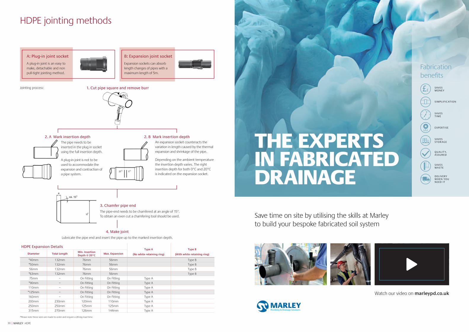
2. A Mark insertion depth
3. Chamfer pipe end
The pipe-end needs to be chamfered at an angle of 15°. To obtain an even cut a chamfering tool should be used.
Jointing process:
HDPE Expansion DetailsType A
(No white retaining ring)
Type B
(With white retaining ring)Diameter Total LengthMin. Insertion Depth @ 20°C
Max. Expansion
*40mm 132mm 76mm 56mm Type B
*50mm 132mm 76mm 56mm Type B
56mm 132mm 76mm 56mm Type B
*63mm 132mm 76mm 56mm Type B
75mm – On Fitting On Fitting Type A
*90mm – On Fitting On Fitting Type A
110mm – On Fitting On Fitting Type A
*125mm – On Fitting On Fitting Type A
160mm – On Fitting On Fitting Type A
200mm 230mm 120mm 110mm Type A
250mm 250mm 125mm 125mm Type A
315mm 270mm 126mm 144mm Type A
*Please note these sizes are made to order and require a 28 day lead time.
An expansion socket counteracts the variation in length caused by the thermal expansion and shrinkage of the pipe.
Depending on the ambient temperature the insertion depth varies. The right insertion depth for both 0°C and 20°C is indicated on the expansion socket.
2. B Mark insertion depth
4. Make joint
Lubricate the pipe end and insert the pipe up to the marked insertion depth.
1. Cut pipe square and remove burr
A: Plug-in joint socket
A plug-in joint is an easy to make, detachable and non pull-tight jointing method.
B: Expansion joint socket
Expansion sockets can absorb length changes of pipes with a maximum length of 5m.
HDPE jointing methods
The pipe needs to be inserted in the plug in socket using the full insertion depth.
A plug-in joint is not to be used to accommodate the expansion and contraction of a pipe system.
THE EXPERTS IN FABRICATED DRAINAGE
Save time on site by utilising the skills at Marley to build your bespoke fabricated soil system
DELIVERY WHEN YOU NEED IT
Fabrication benefits
££SAVES MONEY
SIMPLIFIC ATION
SAVES TIME
E XPERTISE
SAVES STOR AGE
QUALIT Y, ASSURED
SAVES WASTE
Watch our video on marleypd.co.uk
3332 MARLEY HDPE || MARLEY HDPE
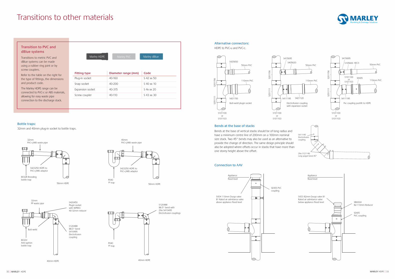
Bends at the base of vertical stacks should be of long radius and have a minimum centre line of 200mm on a 100mm nominal size stack. Two 45° bends may also be used as an alternative to provide the change of direction. The same design principle should also be adopted where offsets occur in stacks that have more than one storey height above the offset.
S411195 Electrofusion coupling
2No S121146 Long spigot bend 45°
Butt-weld plugin socketS251
111 S2
5111
1
S251
111
S201
156 S2
0115
6
S201
156
S425650
S421150 S421120S411195 S411195
S101100 or
S101103
S101100 or
S101103
S101100 or
S101103
S101100 or
S101103
50mm PVC 50mm PVC 50mm PVC
110mm PVC 110mm PVC 110mm PVCSE405
KEC3S105600S405620
S415695S415695
Electrofusion coupling with expansion socket
Pvc coupling pushfit to HDPE
Alternative connectors:HDPE to PVC-u and PVC-c.
Bends at the base of stacks
Connection to AAV
Transitions to other materials
Fitting type Diameter range (mm) Code
Plug-in socket 40-160 S 42 xx 50
Snap socket 40-200 S 40 xx 10
Expansion socket 40-315 S 4x xx 20
Screw coupler 40-110 S 43 xx 30
Bottle traps:32mm and 40mm plug-in socket to bottle traps.
P040 'P' trap
P040 'P' trap
Appliance
flood level
Appliance
flood level
SVD4 110mm Durgo valve B1 Rated air admitance valve above appliance flood level
SVD3 82mm Durgo valve B1 Rated air admitance valve below appliance flood level
40mm PVC-c/ABS waste pipe
56mm HDPE
B032R Resealing bottle trap
B032V Anti-syphon bottle trap
S420450 Plugin socket with WPR43 40-32mm reducer
S120488 88.5° bend with 2No S410495 Electrofusion couplings
SE405 PVC coupling
SRM304 82-110mm Reducer
SE405 PVC coupling
S120488 88.5° bend S410495 Electrofusion coupling
32mm PVC-c/ABS waste pipe
32mm PP waste pipe
S423250 HDPE to PVC-c/ABS adaptor
Butt-weld
S423250 HDPE to PVC-c/ABS adaptor
56mm HDPE
40mm HDPE 40mm HDPE
Transition to PVC and dBlue systems
Transitions to metric PVC and dBlue systems can be made using a rubber ring joint or by screw couplers.
Refer to the table on the right for the type of fittings, the dimensions and product code.
The Marley HDPE range can be connected to PVC-c or ABS materials, allowing for easy waste pipe connection to the discharge stack.
Marley HDPE Marley PVC Marley dBlue
3534 MARLEY HDPE || MARLEY HDPE
Transitions to other materials
All products on this page are available on request unless they have a * against them
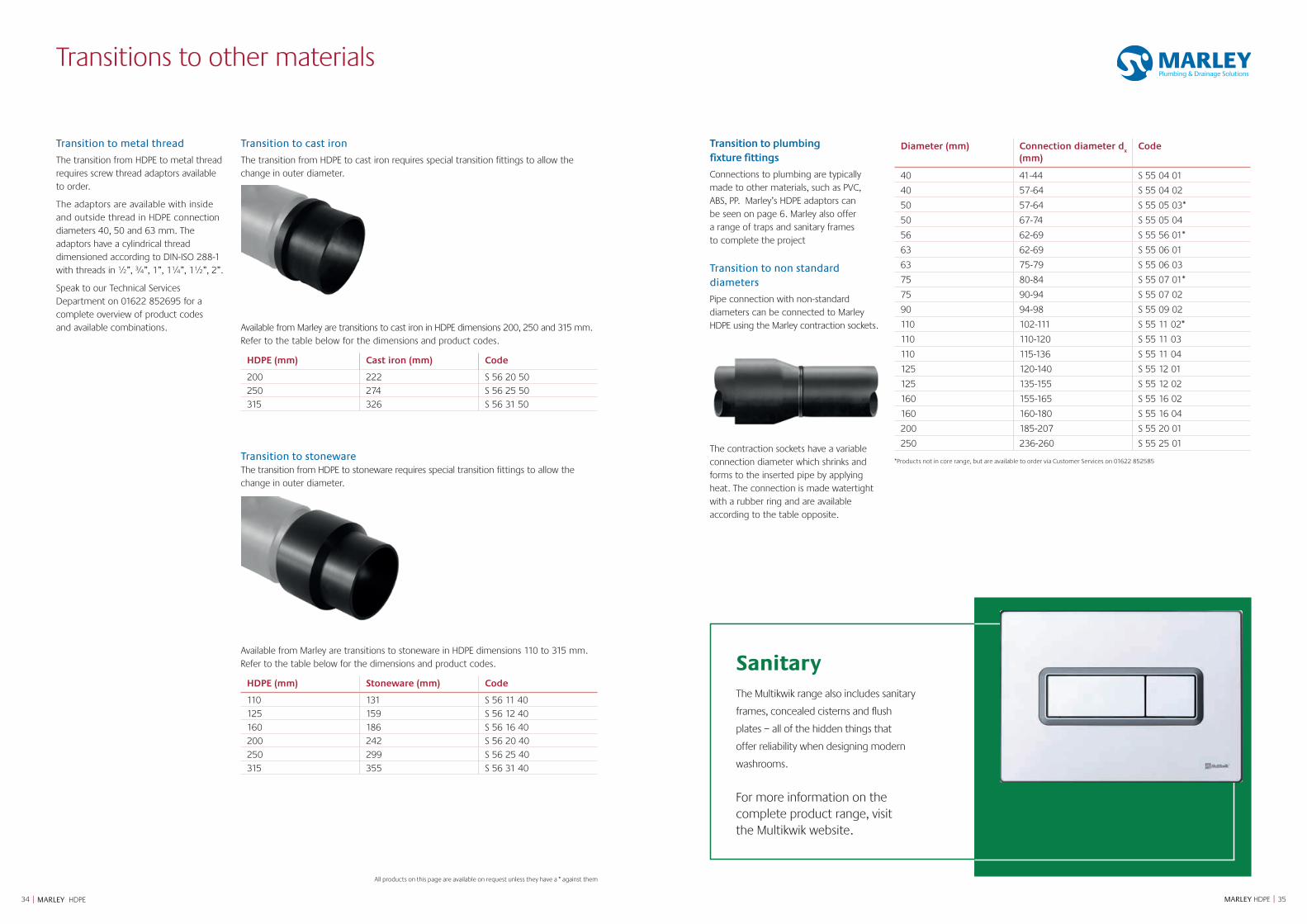
Transition to plumbing fixture fittings
Connections to plumbing are typically made to other materials, such as PVC, ABS, PP. Marley’s HDPE adaptors can be seen on page 6. Marley also offer a range of traps and sanitary frames to complete the project
Transition to non standard diameters
Pipe connection with non-standard diameters can be connected to Marley HDPE using the Marley contraction sockets.
The contraction sockets have a variable connection diameter which shrinks and forms to the inserted pipe by applying heat. The connection is made watertight with a rubber ring and are available according to the table opposite.
Diameter (mm) Connection diameter dx
(mm)Code
40 41-44 S 55 04 01
40 57-64 S 55 04 02
50 57-64 S 55 05 03*
50 67-74 S 55 05 04
56 62-69 S 55 56 01*
63 62-69 S 55 06 01
63 75-79 S 55 06 03
75 80-84 S 55 07 01*
75 90-94 S 55 07 02
90 94-98 S 55 09 02
110 102-111 S 55 11 02*
110 110-120 S 55 11 03
110 115-136 S 55 11 04
125 120-140 S 55 12 01
125 135-155 S 55 12 02
160 155-165 S 55 16 02
160 160-180 S 55 16 04
200 185-207 S 55 20 01
250 236-260 S 55 25 01
Transition to metal thread
The transition from HDPE to metal thread requires screw thread adaptors available to order.
The adaptors are available with inside and outside thread in HDPE connection diameters 40, 50 and 63 mm. The adaptors have a cylindrical thread dimensioned according to DIN-ISO 288-1 with threads in ½”, ¾”, 1”, 1¼”, 1½”, 2”.
Speak to our Technical Services Department on 01622 852695 for a complete overview of product codes and available combinations.
Transition to cast iron
The transition from HDPE to cast iron requires special transition fittings to allow the change in outer diameter.
Available from Marley are transitions to cast iron in HDPE dimensions 200, 250 and 315 mm. Refer to the table below for the dimensions and product codes.
HDPE (mm) Cast iron (mm) Code
200 222 S 56 20 50250 274 S 56 25 50315 326 S 56 31 50
Transition to stonewareThe transition from HDPE to stoneware requires special transition fittings to allow the change in outer diameter.
Available from Marley are transitions to stoneware in HDPE dimensions 110 to 315 mm. Refer to the table below for the dimensions and product codes.
HDPE (mm) Stoneware (mm) Code
110 131 S 56 11 40125 159 S 56 12 40160 186 S 56 16 40200 242 S 56 20 40250 299 S 56 25 40315 355 S 56 31 40
*Products not in core range, but are available to order via Customer Services on 01622 852585
SanitaryThe Multikwik range also includes sanitary
frames, concealed cisterns and flush
plates – all of the hidden things that
offer reliability when designing modern
washrooms.
For more information on the complete product range, visit the Multikwik website.
3736 MARLEY HDPE || MARLEY HDPE
HDPE Bracketry
1. Coupler2. Anchor bracket 3. Mounting plate for
anchor bracket
Support bracket fixed to building structure-brackets must be of sufficient strength to resist forces generated by thermal movement of the pipes
Electrofusion coupler either side of support bracket
1
23
1
1. Guide bracket2. Mounting plate for guide bracket
21
1. Expansion socket2. Clamp liner3. Anchor bracket4. Mounting plate for
anchor bracket
Support bracket fixed to building structure-brackets to be of sufficient strength to resist forces caused by the internal resistance of the expansion socket
Thermal movement of PE pipework
2 31
+4
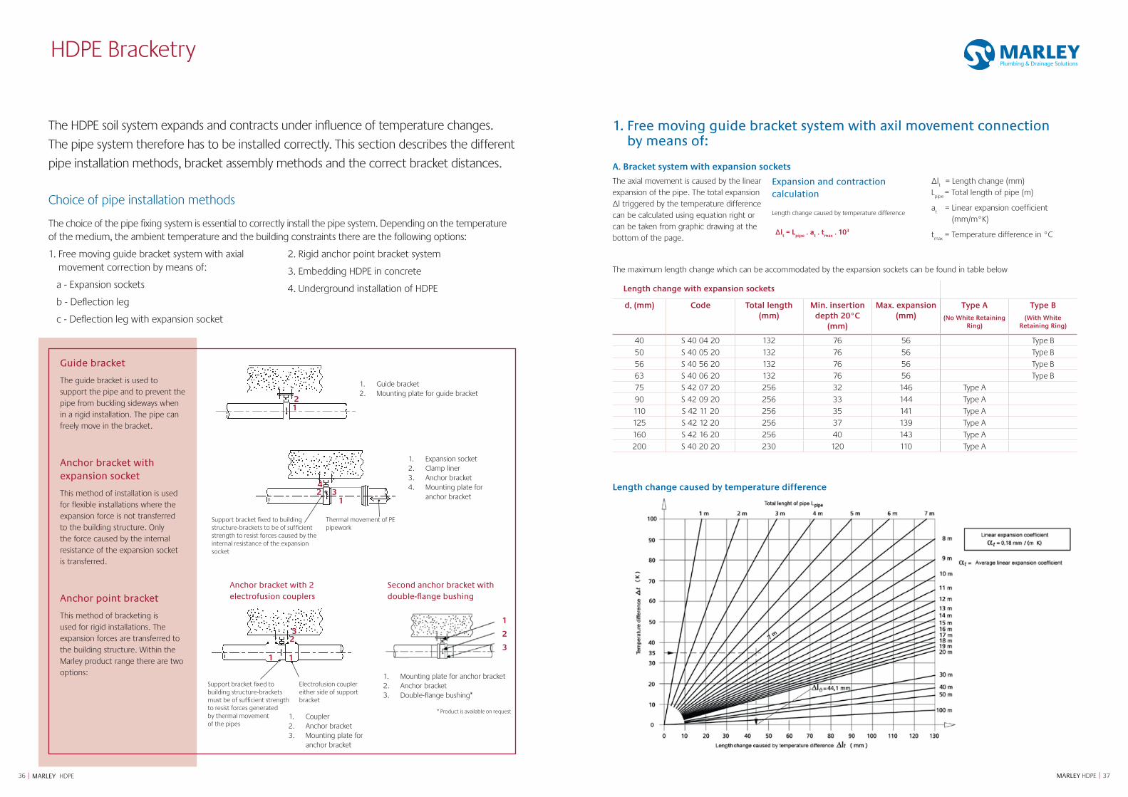
A. Bracket system with expansion sockets
The axial movement is caused by the linear expansion of the pipe. The total expansion Δl triggered by the temperature difference can be calculated using equation right or can be taken from graphic drawing at the bottom of the page.
Expansion and contraction calculation
Length change caused by temperature difference
Δlt
= Length change (mm)L
pipe = Total length of pipe (m)
at
= Linear expansion coefficient (mm/m°K)
tmax
= Temperature difference in °CΔlt = L
pipe . a
t . t
max . 103
The maximum length change which can be accommodated by the expansion sockets can be found in table below
Length change with expansion sockets
d, (mm) Code Total length (mm)
Min. insertion depth 20°C
(mm)
Max. expansion (mm)
Type A(No White Retaining
Ring)
Type B(With White
Retaining Ring)
40 S 40 04 20 132 76 56 Type B50 S 40 05 20 132 76 56 Type B56 S 40 56 20 132 76 56 Type B63 S 40 06 20 132 76 56 Type B75 S 42 07 20 256 32 146 Type A90 S 42 09 20 256 33 144 Type A110 S 42 11 20 256 35 141 Type A125 S 42 12 20 256 37 139 Type A160 S 42 16 20 256 40 143 Type A200 S 40 20 20 230 120 110 Type A
1. Free moving guide bracket system with axil movement connection by means of:
Length change caused by temperature difference
1. Mounting plate for anchor bracket 2. Anchor bracket 3. Double-flange bushing*
2
3
1
* Product is available on request
The HDPE soil system expands and contracts under influence of temperature changes.
The pipe system therefore has to be installed correctly. This section describes the different
pipe installation methods, bracket assembly methods and the correct bracket distances.
Choice of pipe installation methods
The choice of the pipe fixing system is essential to correctly install the pipe system. Depending on the temperature of the medium, the ambient temperature and the building constraints there are the following options:
1. Free moving guide bracket system with axial movement correction by means of:
a - Expansion sockets
b - Deflection leg
c - Deflection leg with expansion socket
2. Rigid anchor point bracket system
3. Embedding HDPE in concrete
4. Underground installation of HDPE
Guide bracket
The guide bracket is used to support the pipe and to prevent the pipe from buckling sideways when in a rigid installation. The pipe can freely move in the bracket.
Anchor bracket with expansion socket
This method of installation is used for flexible installations where the expansion force is not transferred to the building structure. Only the force caused by the internal resistance of the expansion socket is transferred.
Anchor point bracket
This method of bracketing is used for rigid installations. The expansion forces are transferred to the building structure. Within the Marley product range there are two options:
Second anchor bracket with double-flange bushing
Anchor bracket with 2 electrofusion couplers
3938 MARLEY HDPE || MARLEY HDPE
HDPE Bracketry
HDPE expansion sockets can accommodate the expansion and contraction of max. 6m. This rule of thumb can be used when no further calculations are made. This general rule is only applicable with:
Δ ≤ 37.5°C.
The number of expansion sockets can specifically be calculated by using equitation table on previous page.
Pipe section with expansion socket
Example:
Length pipe section (L2 +L
3 +L
4 ): 18 m
Installation temperature: 5°C
Temperature medium: +15°C / +75°C
Temperature difference: 75-5 = 70°K
Total expansion: 18 m x 0.18 mm/mK.
70K = 227 mm expansion length per expansion coupler d110 = 141mm
In a pipe section of 110 mm diameter this results in 227/141 = ~1.6 = 2 expansion sockets. Therefore, based upon the calculation only 2 expansion sockets are needed as opposed to the general rule of thumb (18/6 = 3 expansion sockets). By calculating the maximum expansion a more cost efficient installation can be made.
With short term temperature differences, for example the emptying of a bathtub, a reduction factor of 0.5 can be applied to the temperature difference. In the example this would result in 0.5 x 227/141= ~0.8 = 1 expansion socket.
The general rules can be applied for pipe lengths ≤ 5m in most drainage applications. With extreme high temperatures possibly in combination with a complex route the number of expansion sockets may need to be calculated.
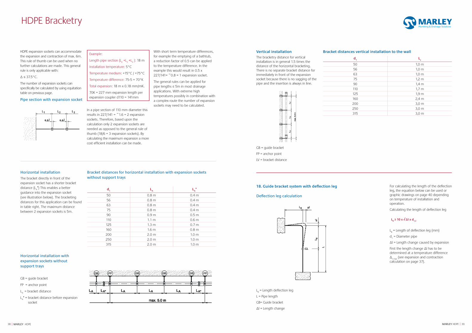
Horizontal installation
The bracket directly in front of the expansion socket has a shorter bracket distance (L
A*) This enables a better
guidance into the expansion socket (see illustration below). The bracketing distances for this application can be found in table right. The maximum distance between 2 expansion sockets is 5m.
Horizontal installation with expansion sockets without support trays
GB = guide bracket
FP = anchor point
LA = bracket distance
LA* = bracket distance before expansion
socket
Bracket distances for horizontal installation with expansion sockets without support trays
d1
LA
LA*
50 0.8 m 0.4 m56 0.8 m 0.4 m63 0.8 m 0.4 m75 0.8 m 0.4 m90 0.9 m 0.5 m110 1.1 m 0.6 m125 1.3 m 0.7 m160 1.6 m 0.8 m200 2.0 m 1.0 m250 2.0 m 1.0 m315 2.0 m 1.0 m
Vertical installationThe bracketry distance for vertical installation is in general 1.5 times the distance of the horizontal bracketing. There is no separate bracket distance for immediately in front of the expansion socket because there is no sagging of the pipe and the insertion is always in line.
GB = guide bracket
FP = anchor point
LV = bracket distance
Bracket distances vertical installation to the wall
d1
Lv
50 1,0 m56 1,0 m63 1,0 m75 1,2 m90 1,4 m110 1,7 m125 1,9 m160 2,4 m200 3,0 m250 3,0 m315 3,0 m
1B. Guide bracket system with deflection leg
Deflection leg calculation
LB = Length deflection leg
L = Pipe length
GB= Guide bracket
Δl = Length change
For calculating the length of the deflection leg, the equation below can be used or graphic drawings on page 40 depending on temperature of installation and operation.
Calculating the length of deflection leg
LB ≥ 10 x √Δl x d
1,2
LB = Length of deflection leg (mm)
d1 = Diameter pipe
Δl = Length change caused by expansion
First the length change Δl has to be determined at a temperature difference Δ
t max (see expansion and contraction
calculation on page 37).
4140 MARLEY HDPE || MARLEY HDPE
HDPE Bracketry
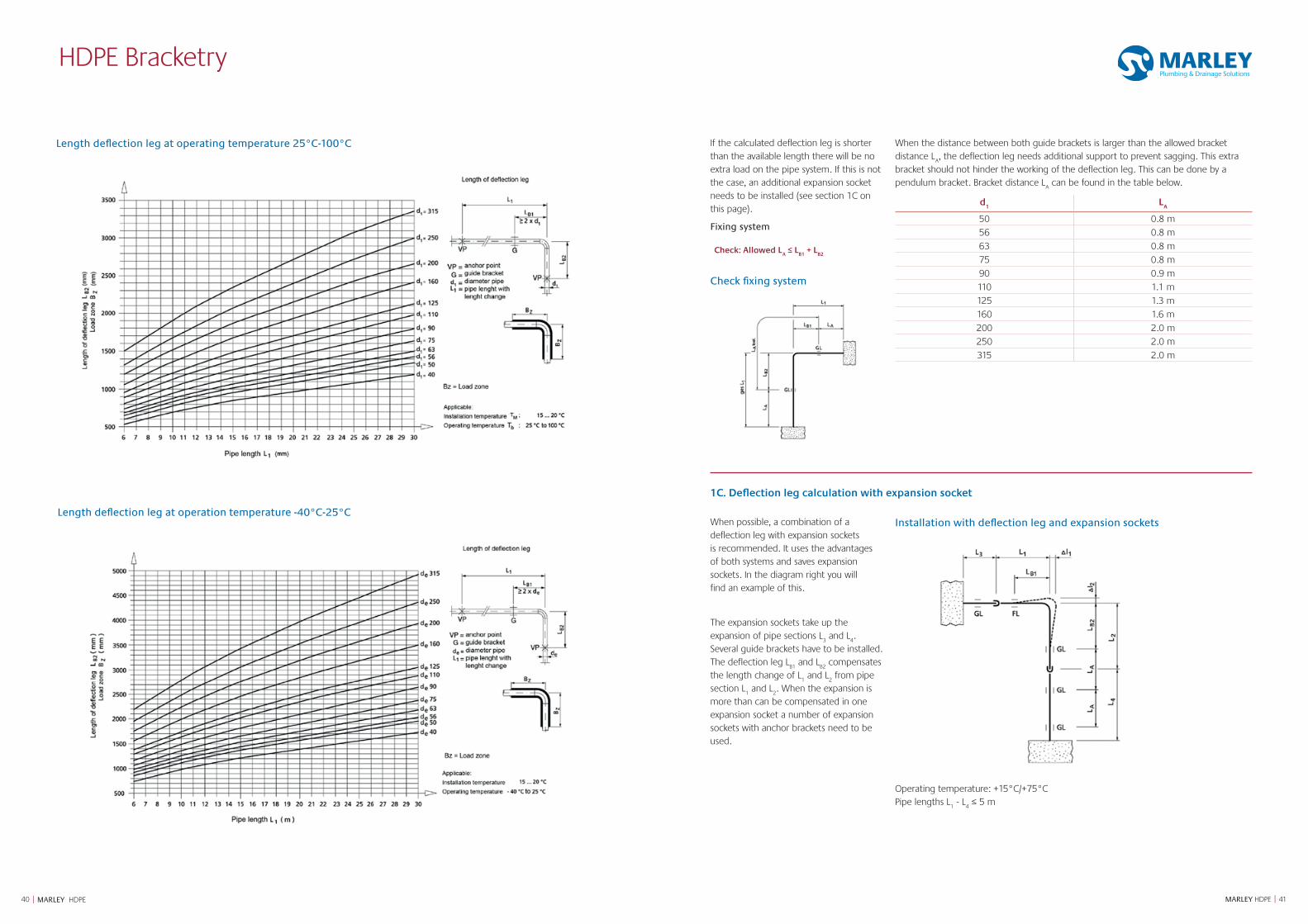
Length deflection leg at operating temperature 25°C-100°C
Length deflection leg at operation temperature -40°C-25°C
1C. Deflection leg calculation with expansion socket
When possible, a combination of a deflection leg with expansion sockets is recommended. It uses the advantages of both systems and saves expansion sockets. In the diagram right you will find an example of this.
The expansion sockets take up the expansion of pipe sections L
3 and L
4.
Several guide brackets have to be installed. The deflection leg L
B1 and L
B2 compensates
the length change of L1 and L
2 from pipe
section L1 and L
2. When the expansion is
more than can be compensated in one expansion socket a number of expansion sockets with anchor brackets need to be used.
Installation with deflection leg and expansion sockets
Operating temperature: +15°C/+75°CPipe lengths L
1 - L
4 ≤ 5 m
If the calculated deflection leg is shorter than the available length there will be no extra load on the pipe system. If this is not the case, an additional expansion socket needs to be installed (see section 1C on this page).
Fixing system
Check: Allowed LA ≤ L
B1 + L
B2
Check fixing system
When the distance between both guide brackets is larger than the allowed bracket distance L
A, the deflection leg needs additional support to prevent sagging. This extra
bracket should not hinder the working of the deflection leg. This can be done by a pendulum bracket. Bracket distance L
A can be found in the table below.
d1
LA
50 0.8 m56 0.8 m63 0.8 m75 0.8 m90 0.9 m110 1.1 m125 1.3 m160 1.6 m200 2.0 m250 2.0 m315 2.0 m
4342 MARLEY HDPE || MARLEY HDPE
HDPE Bracketry
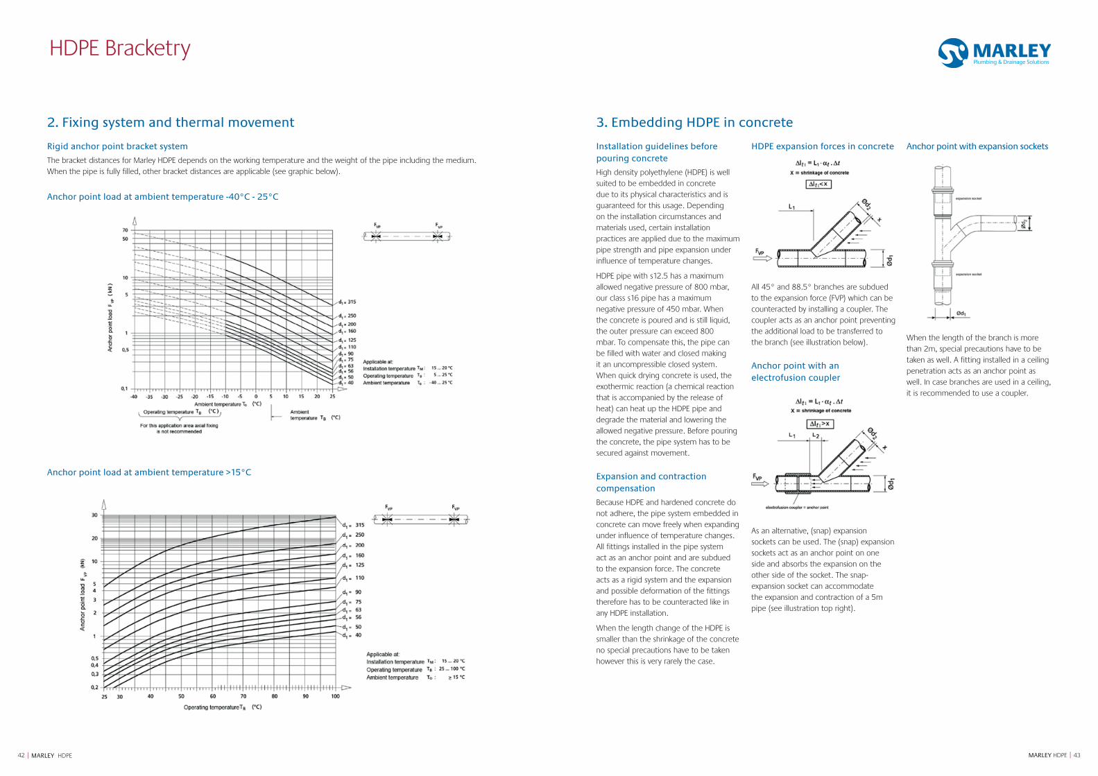
2. Fixing system and thermal movement
Rigid anchor point bracket system
The bracket distances for Marley HDPE depends on the working temperature and the weight of the pipe including the medium. When the pipe is fully filled, other bracket distances are applicable (see graphic below).
Anchor point load at ambient temperature >15°C
Anchor point load at ambient temperature -40°C - 25°C
3. Embedding HDPE in concrete
Installation guidelines before pouring concrete
High density polyethylene (HDPE) is well suited to be embedded in concrete due to its physical characteristics and is guaranteed for this usage. Depending on the installation circumstances and materials used, certain installation practices are applied due to the maximum pipe strength and pipe expansion under influence of temperature changes.
HDPE pipe with s12.5 has a maximum allowed negative pressure of 800 mbar, our class s16 pipe has a maximum negative pressure of 450 mbar. When the concrete is poured and is still liquid, the outer pressure can exceed 800 mbar. To compensate this, the pipe can be filled with water and closed making it an uncompressible closed system. When quick drying concrete is used, the exothermic reaction (a chemical reaction that is accompanied by the release of heat) can heat up the HDPE pipe and degrade the material and lowering the allowed negative pressure. Before pouring the concrete, the pipe system has to be secured against movement.
Expansion and contraction compensation
Because HDPE and hardened concrete do not adhere, the pipe system embedded in concrete can move freely when expanding under influence of temperature changes. All fittings installed in the pipe system act as an anchor point and are subdued to the expansion force. The concrete acts as a rigid system and the expansion and possible deformation of the fittings therefore has to be counteracted like in any HDPE installation.
When the length change of the HDPE is smaller than the shrinkage of the concrete no special precautions have to be taken however this is very rarely the case.
HDPE expansion forces in concrete
All 45° and 88.5° branches are subdued to the expansion force (FVP) which can be counteracted by installing a coupler. The coupler acts as an anchor point preventing the additional load to be transferred to the branch (see illustration below).
Anchor point with an electrofusion coupler
As an alternative, (snap) expansion sockets can be used. The (snap) expansion sockets act as an anchor point on one side and absorbs the expansion on the other side of the socket. The snap-expansion socket can accommodate the expansion and contraction of a 5m pipe (see illustration top right).
Anchor point with expansion sockets
When the length of the branch is more than 2m, special precautions have to be taken as well. A fitting installed in a ceiling penetration acts as an anchor point as well. In case branches are used in a ceiling, it is recommended to use a coupler.
4544 MARLEY HDPE || MARLEY HDPE
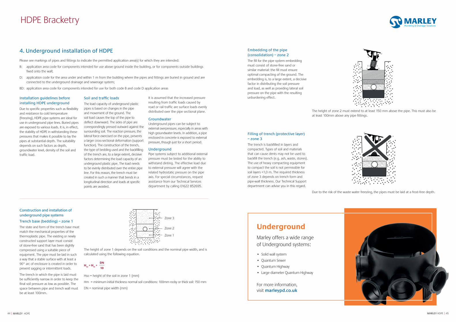
4. Underground installation of HDPE
Please see markings of pipes and fittings to indicate the permitted application area(s) for which they are intended:
B: application area code for components intended for use above ground inside the building, or for components outside buildings fixed onto the wall;
D: application code for the area under and within 1 m from the building where the pipes and fittings are buried in ground and are connected to the underground drainage and sewerage system;
BD: application area code for components intended for use for both code B and code D application areas
Installation guidelines before installing HDPE underground
Due to specific properties such as flexibility and resistance to cold temperature (freezing), HDPE pipe systems are ideal for use in underground pipe lines. Buried pipes are exposed to various loads. It is, in effect, the stability of HDPE in withstanding these pressures that makes it possible to lay the pipes at substantial depth. The suitability depends on such factors as depth, groundwater level, density of the soil and traffic load.
Soil and traffic loads
The load capacity of underground plastic pipes is based on changes in the pipe and movement of the ground. The soil load causes the top of the pipe to deflect downward. The sides of pipe are correspondingly pressed outward against the surrounding soil. The reaction pressure, the lateral force exercised on the pipe, prevents a larger cross-sectional deformation (support function). The construction of the trench, the type of bedding used and the backfilling of the trench are, to a large extent, decisive factors determining the load capacity of an underground plastic pipe. The load needs to be evenly distributed over the entire pipe line. For this reason, the trench must be created in such a manner that bends in a longitudinal direction and loads at specific points are avoided.
It is assumed that the increased pressure resulting from traffic loads caused by road or rail traffic are surface loads evenly distributed over the pipe sectional plane.
Groundwater Underground pipes can be subject to external overpressure, especially in areas with high groundwater levels. In addition, a pipe enclosed in concrete is exposed to external pressure, though just for a short period.
UndergroundPipe systems subject to additional external pressure must be tested for the ability to withstand dinting. The effective load due to external pressure will agree with the related hydrostatic pressure on the pipe axis. For special circumstances, request assistance from our Technical Services department by calling 01622 852695.
HDPE Bracketry
Construction and installation of underground pipe systems
Trench base (bedding) – zone 1
The state and form of the trench base must match the mechanical properties of the thermoplastic pipe. The existing or newly constructed support layer must consist of stone-free sand that has been slightly compressed using a suitable piece of equipment. The pipe must be laid in such a way that a stable surface with at least a 90° arc of enclosure is created in order to prevent sagging or intermittent loads.
The trench in which the pipe is laid must be sufficiently narrow in order to keep the final soil pressure as low as possible. The space between pipe and trench wall must be at least 100mm.
The height of zone 1 depends on the soil conditions and the nominal pipe width, and is calculated using the following equation.
Hso
= Hm
+ DN
10
Hso = height of the soil in zone 1 (mm)
Hm = minimum initial thickness normal soil conditions: 100mm rocky or thick soil: 150 mm
DN = nominal pipe width (mm)
Embedding of the pipe (consolidation) – zone 2
The fill for the pipe system embedding must consist of stone-free sand or similar material: the fill must ensure optimal compacting of the ground. The embedding is, to a large extent, a decisive factor in distributing the soil pressure and load, as well as providing lateral soil pressure on the pipe with the resulting unburdening effect.
The height of zone 2 must extend to at least 150 mm above the pipe. This must also be at least 100mm above any pipe fittings.
Filling of trench (protective layer) – zone 3
The trench is backfilled in layers and compacted. Types of soil and materials that can cause dents may not be used to backfill the trench (e.g. ash, waste, stones). The use of heavy compacting equipment to compact the soil is not permissible for soil layers <1,0 m. The required thickness of zone 3 depends on trench form and pipe-wall thickness. Our Technical Support department can advise you in this regard.
Due to the risk of the waste water freezing, the pipes must be laid at a frost-free depth.
Zone 3
Zone 2
Zone 1
UndergroundMarley offers a wide range of Underground systems:
• Solid wall system
• Quantum Sewer
• Quantum Highway
• Large diameter Quantum Highway
For more information, visit marleypd.co.uk
46 | MARLEY HDPE
ACTIVE DRAINAGE VENTILATION
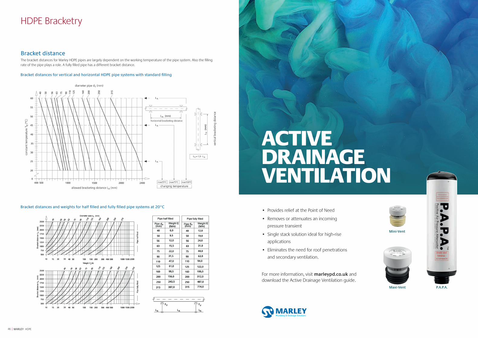
Bracket distanceThe bracket distances for Marley HDPE pipes are largely dependent on the working temperature of the pipe system. Also the filling rate of the pipe plays a role. A fully filled pipe has a different bracket distance.
Bracket distances for vertical and horizontal HDPE pipe systems with standard filling
Bracket distances and weights for half filled and fully filled pipe systems at 20°C
HDPE Bracketry
Maxi-Vent P.A.P.A.
Mini-Vent
• Provides relief at the Point of Need
• Removes or attenuates an incoming
pressure transient
• Single stack solution ideal for high-rise
applications
• Eliminates the need for roof penetrations
and secondary ventilation.
For more information, visit marleypd.co.uk and download the Active Drainage Ventilation guide.
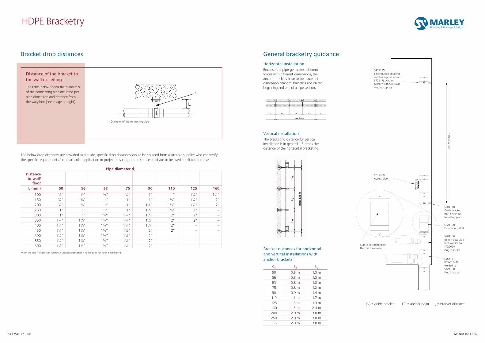
4948 MARLEY HDPE || MARLEY HDPE
HDPE Bracketry
Horizontal installation Because the pipe generates different forces with different dimensions, the anchor brackets have to be placed at dimension changes, branches and on the beginning and end of a pipe section.
General bracketry guidance
Bracket distances for horizontal and vertical installations with anchor brackets
d1
LA
LV
50 0.8 m 1.0 m56 0.8 m 1.0 m63 0.8 m 1.0 m75 0.8 m 1.2 m90 0.9 m 1.4 m110 1.1 m 1.7 m125 1.3 m 1.9 m160 1.6 m 2.4 m200 2.0 m 3.0 m250 2.0 m 3.0 m315 2.0 m 3.0 m
Vertical installationThe bracketing distance for vertical installation is in general 1.5 times the distance of the horizontal bracketing.
GB = guide bracket FP = anchor point LA = bracket distance
S421120Expansion socket
S231100Access pipe
S20115656mm boss pipe butt-welded toS425650Plug in socket
S251111Branch butt-welded toS421150Plug in socket
S411195Electrofusion coupling usedas support aboveS701178Anchor bracket withS709478mounting plate
S701110Guide bracket withS709410Mounting plate
Gap to accommodatethermal movement
1700mm
max
S411195Electrofusion coupling used as support above S701178 Anchor bracket with S709478 mounting plate
S231100Access pipe
Gap to accommodatethermal movement
S701110Guide bracket with S709410 Mounting plate
S421120Expansion socket
S20115656mm boss pipe butt-welded to S425650 Plug in socket
S251111Branch butt-welded to S421150 Plug in socket
1700mm
max
The below drop distances are provided as a guide, specific drop distances should be sourced from a suitable supplier who can verify the specific requirements for a particular application or project ensuring drop distances that are to be used are fit-for-purpose.
Pipe diameter d1
Distance to wall/
floorL (mm) 50 56 63 75 90 110 125 160
100 ½“ ½“ ¾“ ¾“ 1“ 1“ 1¼“ 1½”150 ¾“ ¾“ 1“ 1“ 1“ 1¼“ 1¼“ 2”200 ¾“ ¾“ 1“ 1“ 1¼“ 1½” 1½” 2”250 1” 1” 1” 1” 1¼“ 1½” 2” –300 1” 1” 1¼“ 1¼“ 1¼“ 2” 2” –350 1¼“ 1¼“ 1¼“ 1¼“ 1½” 2” 2” –400 1¼“ 1¼“ 1¼“ 1¼“ 1½” 2” – –450 1¼“ 1¼“ 1½” 1½” 2” 2” – –500 1¼“ 1¼“ 1½” 1½” 2” – – –550 1¼“ 1¼“ 1½” 1½” 2” – – –600 1½” 1½” 1½” 1½” 2” – – –
1 = Diameter of the connecting pipe
Distance of the bracket to the wall or ceiling
The table below shows the diameters of the connecting pipe are listed per pipe dimension and distance from the wall/floor (see image on right).
Bracket drop distances
When the pipe is larger than 160mm, a special construction is needed and has to be dimensioned.
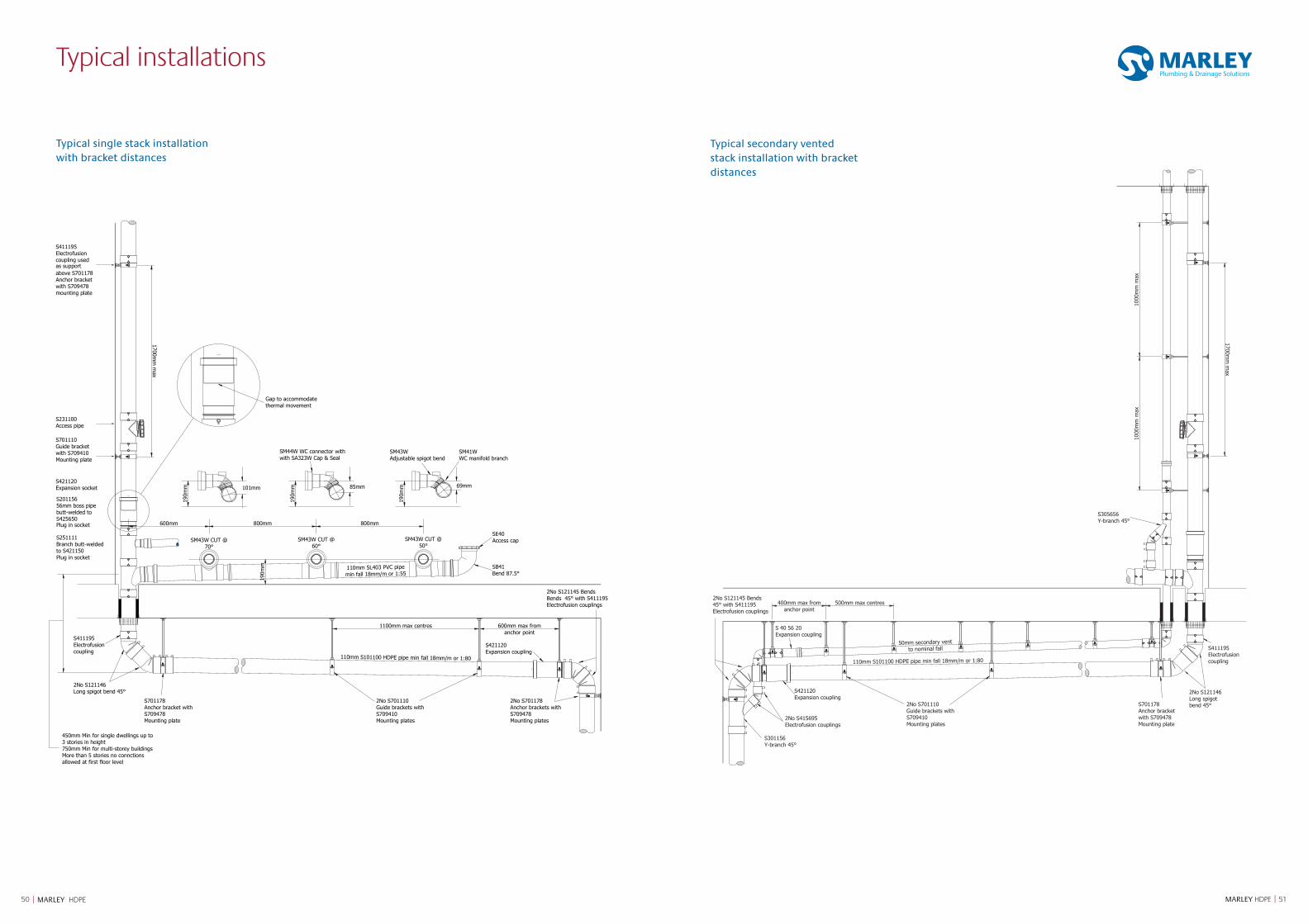
5150 MARLEY HDPE || MARLEY HDPE
Typical single stack installation with bracket distances
Typical secondary vented stack installation with bracket distances
101mm 85mm 69mm
SM43W CUT @70°
SM43W CUT @60°
SM43W CUT @50°
Gap to accommodatethermal movement
1700mm
max
800mm 800mm600mm
190m
m
450mm Min for single dwellings up to3 stories in height750mm Min for multi-storey buildingsMore than 5 stories no connctionsallowed at first floor level
2No S121146Long spigot bend 45°
S411195Electrofusioncoupling
S701178Anchor bracket withS709478Mounting plate
2No S701178Anchor brackets withS709478Mounting plates
S421120Expansion coupling
2No S701110Guide brackets withS709410Mounting plates
110mm S101100 HDPE pipe min fall 18mm/m or 1:80
110mm SL403 PVC pipemin fall 18mm/m or 1:55
1100mm max centres 600mm max fromanchor point
SB41Bend 87.5°
SE40Access cap
190m
m
190m
m
190m
m
SM41WWC manifold branch
SM43WAdjustable spigot bend
SM44W WC connector with
S421120Expansion socket
S20115656mm boss pipe butt-welded to S425650Plug in socket
S251111Branch butt-welded to S421150Plug in socket
S411195Electrofusion coupling used as support above S701178Anchor bracket with S709478mounting plate
S231100Access pipe
S701110Guide bracket with S709410Mounting plate with SA323W Cap & Seal
Electrofusion couplings
2No S121145 BendsBends 45° with S411195
1700mm
max
1000
mm
max
1000
mm
max
400mm max fromanchor point
500mm max centres
50mm secondary ventto nominal fall
Long spigot bend 45°
S411195Electrofusioncoupling
S701178Anchor bracket with S709478Mounting plate
Electrofusion couplings
2No S415695Electrofusion couplings
S421120Expansion coupling
2No S701110Guide brackets withS709410Mounting plates
110mm S101100 HDPE pipe min fall 18mm/m or 1:80
S 40 56 20Expansion coupling
S305656Y-branch 45°
S301156Y-branch 45°
2No S121145 Bends45° with S411195
2No S121146
Typical installations
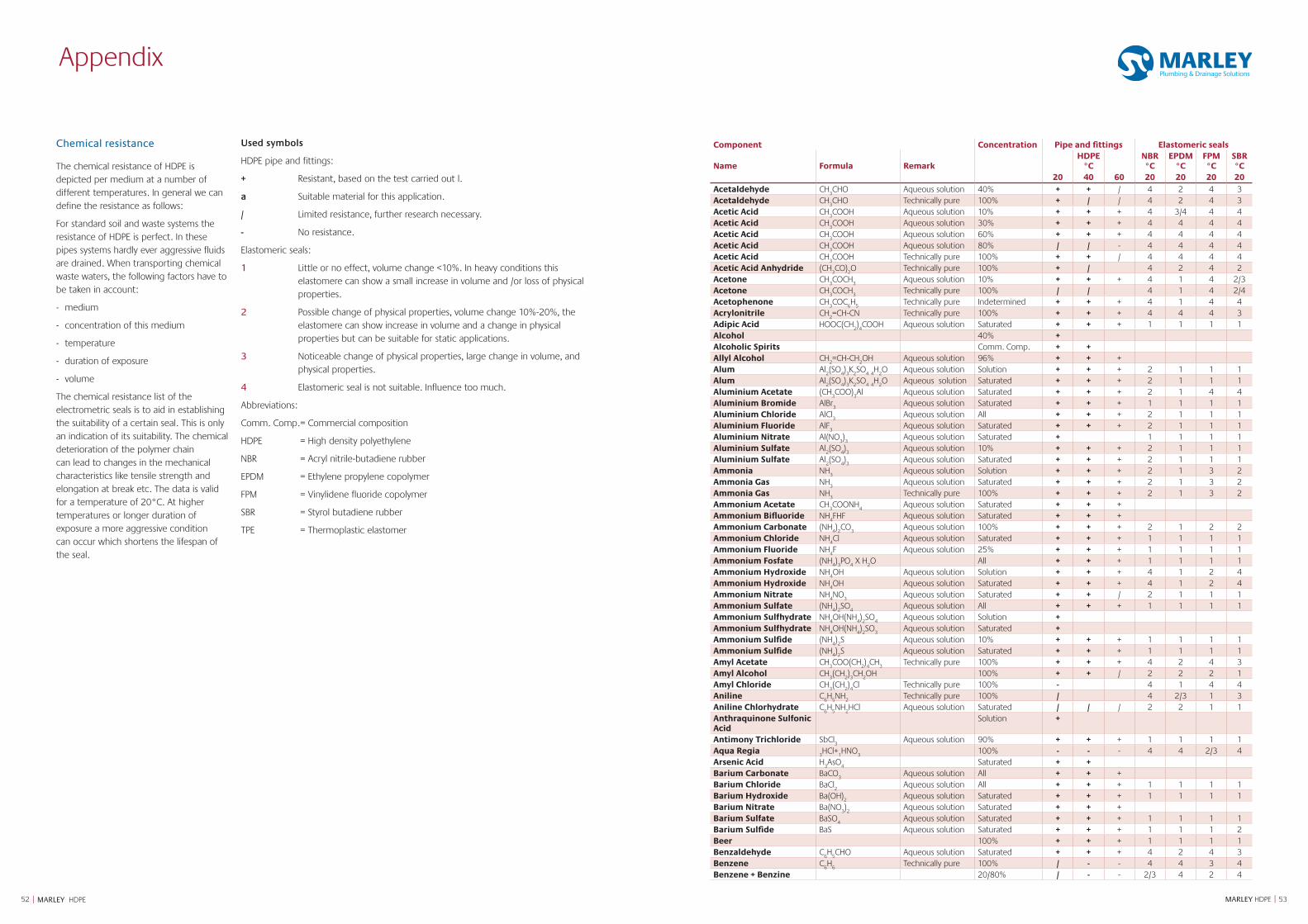
5352 MARLEY HDPE || MARLEY HDPE
Appendix
Chemical resistance
The chemical resistance of HDPE is depicted per medium at a number of different temperatures. In general we can define the resistance as follows:
For standard soil and waste systems the resistance of HDPE is perfect. In these pipes systems hardly ever aggressive fluids are drained. When transporting chemical waste waters, the following factors have to be taken in account:
- medium
- concentration of this medium
- temperature
- duration of exposure
- volume
The chemical resistance list of the electrometric seals is to aid in establishing the suitability of a certain seal. This is only an indication of its suitability. The chemical deterioration of the polymer chain can lead to changes in the mechanical characteristics like tensile strength and elongation at break etc. The data is valid for a temperature of 20°C. At higher temperatures or longer duration of exposure a more aggressive condition can occur which shortens the lifespan of the seal.
Used symbols
HDPE pipe and fittings:
+ Resistant, based on the test carried out l.
a Suitable material for this application.
/ Limited resistance, further research necessary.
- No resistance.
Elastomeric seals:
1 Little or no effect, volume change <10%. In heavy conditions this elastomere can show a small increase in volume and /or loss of physical properties.
2 Possible change of physical properties, volume change 10%-20%, the elastomere can show increase in volume and a change in physical properties but can be suitable for static applications.
3 Noticeable change of physical properties, large change in volume, and physical properties.
4 Elastomeric seal is not suitable. Influence too much.
Abbreviations:
Comm. Comp. = Commercial composition
HDPE = High density polyethylene
NBR = Acryl nitrile-butadiene rubber
EPDM = Ethylene propylene copolymer
FPM = Vinylidene fluoride copolymer
SBR = Styrol butadiene rubber
TPE = Thermoplastic elastomer
Component Concentration Pipe and fittings Elastomeric seals
Name Formula RemarkHDPE
°CNBR°C
EPDM°C
FPM°C
SBR°C
20 40 60 20 20 20 20Acetaldehyde CH
3CHO Aqueous solution 40% + + / 4 2 4 3
Acetaldehyde CH3CHO Technically pure 100% + / / 4 2 4 3
Acetic Acid CH3COOH Aqueous solution 10% + + + 4 3/4 4 4
Acetic Acid CH3COOH Aqueous solution 30% + + + 4 4 4 4
Acetic Acid CH3COOH Aqueous solution 60% + + + 4 4 4 4
Acetic Acid CH3COOH Aqueous solution 80% / / - 4 4 4 4
Acetic Acid CH3COOH Technically pure 100% + + / 4 4 4 4
Acetic Acid Anhydride (CH3CO)
2O Technically pure 100% + / 4 2 4 2
Acetone CH3COCH
3Aqueous solution 10% + + + 4 1 4 2/3
Acetone CH3COCH
3Technically pure 100% / / 4 1 4 2/4
Acetophenone CH3COC
6H
5Technically pure Indetermined + + + 4 1 4 4
Acrylonitrile CH2=CH-CN Technically pure 100% + + + 4 4 4 3
Adipic Acid HOOC(CH2)4COOH Aqueous solution Saturated + + + 1 1 1 1
Alcohol 40% +Alcoholic Spirits Comm. Comp. + +Allyl Alcohol CH
2=CH-CH
2OH Aqueous solution 96% + + +
Alum Al2(SO
4)3K
2SO
4 4H
2O Aqueous solution Solution + + + 2 1 1 1
Alum Al2(SO
4)3K
2SO
4 4H
2O Aqueous solution Saturated + + + 2 1 1 1
Aluminium Acetate (CH3COO)
3Al Aqueous solution Saturated + + + 2 1 4 4
Aluminium Bromide AlBr3
Aqueous solution Saturated + + + 1 1 1 1Aluminium Chloride AlCl
3Aqueous solution All + + + 2 1 1 1
Aluminium Fluoride AlF3
Aqueous solution Saturated + + + 2 1 1 1Aluminium Nitrate Al(NO
3)3
Aqueous solution Saturated + 1 1 1 1Aluminium Sulfate Al
2(SO
4)3
Aqueous solution 10% + + + 2 1 1 1Aluminium Sulfate Al
2(SO
4)3
Aqueous solution Saturated + + + 2 1 1 1Ammonia NH
3Aqueous solution Solution + + + 2 1 3 2
Ammonia Gas NH3
Aqueous solution Saturated + + + 2 1 3 2Ammonia Gas NH
3Technically pure 100% + + + 2 1 3 2
Ammonium Acetate CH3COONH
4Aqueous solution Saturated + + +
Ammonium Bifluoride NH4FHF Aqueous solution Saturated + + +
Ammonium Carbonate (NH4)2CO
3Aqueous solution 100% + + + 2 1 2 2
Ammonium Chloride NH4Cl Aqueous solution Saturated + + + 1 1 1 1
Ammonium Fluoride NH4F Aqueous solution 25% + + + 1 1 1 1
Ammonium Fosfate (NH4)3PO
4 X H
2O All + + + 1 1 1 1
Ammonium Hydroxide NH4OH Aqueous solution Solution + + + 4 1 2 4
Ammonium Hydroxide NH4OH Aqueous solution Saturated + + + 4 1 2 4
Ammonium Nitrate NH4NO
3Aqueous solution Saturated + + / 2 1 1 1
Ammonium Sulfate (NH4)2SO
4Aqueous solution All + + + 1 1 1 1
Ammonium Sulfhydrate NH4OH(NH
4)2SO
4Aqueous solution Solution +
Ammonium Sulfhydrate NH4OH(NH
4)2SO
3Aqueous solution Saturated +
Ammonium Sulfide (NH4)2S Aqueous solution 10% + + + 1 1 1 1
Ammonium Sulfide (NH4)2S Aqueous solution Saturated + + + 1 1 1 1
Amyl Acetate CH3COO(CH
2)4CH
3Technically pure 100% + + + 4 2 4 3
Amyl Alcohol CH3(CH
2)3CH
2OH 100% + + / 2 2 2 1
Amyl Chloride CH3(CH
2)4Cl Technically pure 100% - 4 1 4 4
Aniline C6H
5NH
2Technically pure 100% / 4 2/3 1 3
Aniline Chlorhydrate C6H
5NH
2HCl Aqueous solution Saturated / / / 2 2 1 1
Anthraquinone Sulfonic Acid
Solution +
Antimony Trichloride SbCl3
Aqueous solution 90% + + + 1 1 1 1Aqua Regia
3HCl+
1HNO
3100% - - - 4 4 2/3 4
Arsenic Acid H3AsO
4Saturated + +
Barium Carbonate BaCO3
Aqueous solution All + + +Barium Chloride BaCl
2Aqueous solution All + + + 1 1 1 1
Barium Hydroxide Ba(OH)2
Aqueous solution Saturated + + + 1 1 1 1Barium Nitrate Ba(NO
3)2
Aqueous solution Saturated + + +Barium Sulfate BaSO
4Aqueous solution Saturated + + + 1 1 1 1
Barium Sulfide BaS Aqueous solution Saturated + + + 1 1 1 2Beer 100% + + + 1 1 1 1Benzaldehyde C
6H
5CHO Aqueous solution Saturated + + + 4 2 4 3
Benzene C6H
6Technically pure 100% / - - 4 4 3 4
Benzene + Benzine 20/80% / - - 2/3 4 2 4
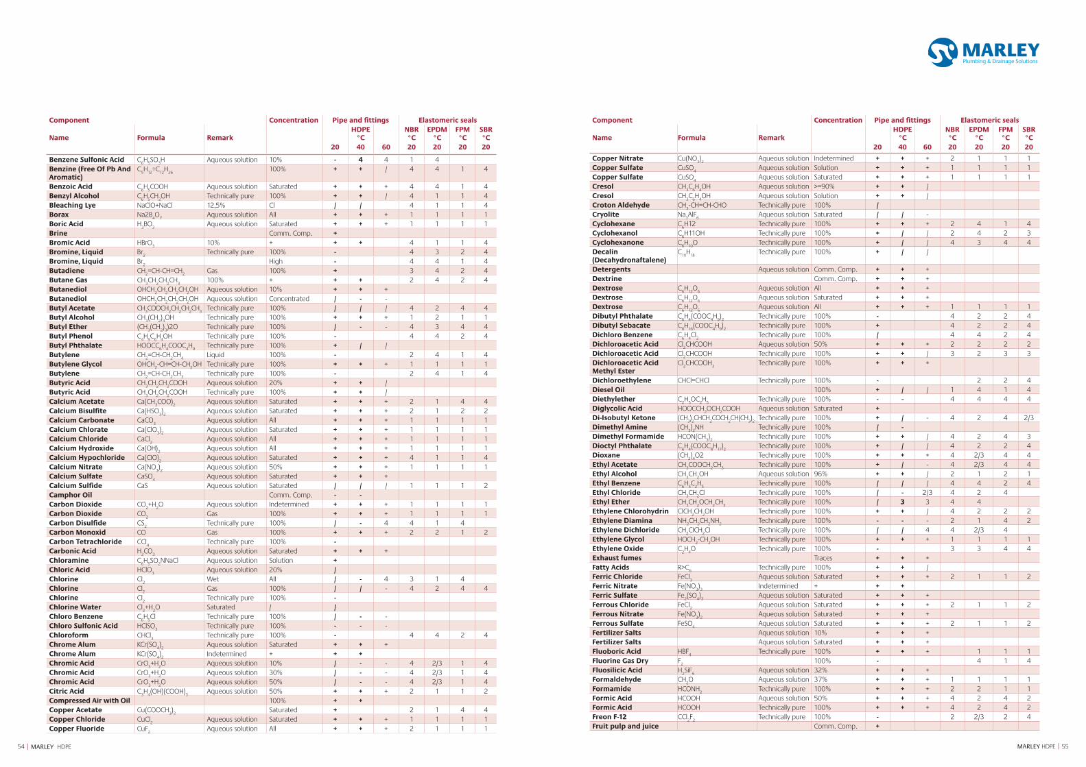
5554 MARLEY HDPE || MARLEY HDPE
Component Concentration Pipe and fittings Elastomeric seals
Name Formula RemarkHDPE
°CNBR°C
EPDM°C
FPM°C
SBR°C
20 40 60 20 20 20 20
Benzene Sulfonic Acid C6H
5SO
3H Aqueous solution 10% - 4 4 1 4
Benzine (Free Of Pb And Aromatic)
C5H
12÷C
12H
26100% + + / 4 4 1 4
Benzoic Acid C6H
5COOH Aqueous solution Saturated + + + 4 4 1 4
Benzyl Alcohol C6H
5CH
2OH Technically pure 100% + + / 4 1 1 4
Bleaching Lye NaClO+NaCl 12,5% Cl / / 4 1 1 4Borax Na2B
4O
7Aqueous solution All + + + 1 1 1 1
Boric Acid H3BO
3Aqueous solution Saturated + + + 1 1 1 1
Brine Comm. Comp. +Bromic Acid HBrO
310% + + + 4 1 1 4
Bromine, Liquid Br2
Technically pure 100% - 4 3 2 4Bromine, Liquid Br
2High - 4 4 1 4
Butadiene CH2=CH-CH=CH
2Gas 100% + 3 4 2 4
Butane Gas CH3CH
2CH
2CH
3100% + + + 2 4 2 4
Butanediol OHCH2CH
2CH
2CH
2OH Aqueous solution 10% + + +
Butanediol OHCH2CH
2CH
2CH
2OH Aqueous solution Concentrated / - -
Butyl Acetate CH3COOCH
2CH
2CH
2CH
3Technically pure 100% / / / 4 2 4 4
Butyl Alcohol CH3(CH
2)3OH Technically pure 100% + + + 1 2 1 1
Butyl Ether (CH3(CH
2)3)2O Technically pure 100% / - - 4 3 4 4
Butyl Phenol C4H
9C
6H
4OH Technically pure 100% - 4 4 2 4
Butyl Phthalate HOOCC6H
4COOC
4H
9Technically pure 100% + / /
Butylene CH2=CH-CH
2CH
4Liquid 100% - 2 4 1 4
Butylene Glycol OHCH2-CH=CH-CH
2OH Technically pure 100% + + + 1 1 1 1
Butylene CH2=CH-CH
2CH
3Technically pure 100% - 2 4 1 4
Butyric Acid CH3CH
2CH
2COOH Aqueous solution 20% + + /
Butyric Acid CH3CH
2CH
2COOH Technically pure 100% + + /
Calcium Acetate Ca(CH3COO)
2Aqueous solution Saturated + + + 2 1 4 4
Calcium Bisulfite Ca(HSO3)2
Aqueous solution Saturated + + + 2 1 2 2Calcium Carbonate CaCO
3Aqueous solution All + + + 1 1 1 1
Calcium Chlorate Ca(ClO3)2
Aqueous solution Saturated + + + 1 1 1 1Calcium Chloride CaCl
2Aqueous solution All + + + 1 1 1 1
Calcium Hydroxide Ca(OH)2
Aqueous solution All + + + 1 1 1 1Calcium Hypochloride Ca(CIO)
2Aqueous solution Saturated + + + 4 1 1 4
Calcium Nitrate Ca(NO3)2
Aqueous solution 50% + + + 1 1 1 1Calcium Sulfate CaSO
4Aqueous solution Saturated + + +
Calcium Sulfide CaS Aqueous solution Saturated / / / 1 1 1 2Camphor Oil Comm. Comp. - -Carbon Dioxide CO
2+H
2O Aqueous solution Indetermined + + + 1 1 1 1
Carbon Dioxide CO2
Gas 100% + + + 1 1 1 1Carbon Disulfide CS
2Technically pure 100% / - 4 4 1 4
Carbon Monoxid CO Gas 100% + + + 2 2 1 2Carbon Tetrachloride CCl
4Technically pure 100% -
Carbonic Acid H2CO
3Aqueous solution Saturated + + +
Chloramine C6H
5SO
2NNaCl Aqueous solution Solution +
Chloric Acid HClO3
Aqueous solution 20% /Chlorine Cl
2Wet All / - 4 3 1 4
Chlorine Cl2
Gas 100% / / - 4 2 4 4Chlorine Cl
2Technically pure 100% -
Chlorine Water Cl2+H
2O Saturated / /
Chloro Benzene C6H
5Cl Technically pure 100% / - -
Chloro Sulfonic Acid HClSO3
Technically pure 100% - - -Chloroform CHCl
3Technically pure 100% - 4 4 2 4
Chrome Alum KCr(SO4)2
Aqueous solution Saturated + + +Chrome Alum KCr(SO
4)2
Indetermined + + +Chromic Acid CrO
3+H
2O Aqueous solution 10% / - - 4 2/3 1 4
Chromic Acid CrO3+H
2O Aqueous solution 30% / - - 4 2/3 1 4
Chromic Acid CrO3+H
2O Aqueous solution 50% / - - 4 2/3 1 4
Citric Acid C3H
4(OH)(COOH)
3Aqueous solution 50% + + + 2 1 1 2
Compressed Air with Oil 100% + +Copper Acetate Cu(COOCH
3)2
Saturated + 2 1 4 4Copper Chloride CuCl
2Aqueous solution Saturated + + + 1 1 1 1
Copper Fluoride CuF2
Aqueous solution All + + + 2 1 1 1
Component Concentration Pipe and fittings Elastomeric seals
Name Formula RemarkHDPE
°CNBR°C
EPDM°C
FPM°C
SBR°C
20 40 60 20 20 20 20
Copper Nitrate Cu(NO3)2
Aqueous solution Indetermined + + + 2 1 1 1Copper Sulfate CuSO
4Aqueous solution Solution + + + 1 1 1 1
Copper Sulfate CuSO4
Aqueous solution Saturated + + + 1 1 1 1Cresol CH
3C
6H
4OH Aqueous solution >=90% + + /
Cresol CH3C
6H
4OH Aqueous solution Solution + + /
Croton Aldehyde CH3-CH=CH-CHO Technically pure 100% /
Cryolite Na3AlF
6Aqueous solution Saturated / / -
Cyclohexane C6H12 Technically pure 100% + + + 2 4 1 4
Cyclohexanol C6H11OH Technically pure 100% + / / 2 4 2 3
Cyclohexanone C6H
10O Technically pure 100% + / / 4 3 4 4
Decalin(Decahydronaftalene)
C10
H18
Technically pure 100% + / /
Detergents Aqueous solution Comm. Comp. + + +Dextrine Comm. Comp. + + +Dextrose C
6H
12O
6Aqueous solution All + + +
Dextrose C6H
12O
6Aqueous solution Saturated + + +
Dextrose C6H
12O
6Aqueous solution All + + + 1 1 1 1
Dibutyl Phthalate C6H
4(COOC
4H
9)2
Technically pure 100% - 4 2 2 4Dibutyl Sebacate C
8H
16(COOC
4H
9)2
Technically pure 100% + 4 2 2 4Dichloro Benzene C
6H
4Cl
2Technically pure 100% / 4 4 2 4
Dichloroacetic Acid Cl2CHCOOH Aqueous solution 50% + + + 2 2 2 2
Dichloroacetic Acid Cl2CHCOOH Technically pure 100% + + / 3 2 3 3
Dichloroacetic Acid Methyl Ester
Cl2CHCOOH
3Technically pure 100% + + +
Dichloroethylene CHCl=CHCl Technically pure 100% - 2 2 4Diesel Oil 100% + / / 1 4 1 4Diethylether C
2H
5OC
2H
5Technically pure 100% - - 4 4 4 4
Diglycolic Acid HOOCCH2OCH
2COOH Aqueous solution Saturated +
Di-Isobutyl Ketone (CH3)2CHCH
2COCH
2CH(CH
3)2
Technically pure 100% + / - 4 2 4 2/3Dimethyl Amine (CH
3)2NH Technically pure 100% / -
Dimethyl Formamide HCON(CH3)2
Technically pure 100% + + / 4 2 4 3Dioctyl Phthalate C
6H
4(COOC
8H
17)2
Technically pure 100% + / / 4 2 2 4Dioxane (CH
2)4O2 Technically pure 100% + + + 4 2/3 4 4
Ethyl Acetate CH3COOCH
2CH
3Technically pure 100% + / - 4 2/3 4 4
Ethyl Alcohol CH3CH
2OH Aqueous solution 96% + + / 2 1 2 1
Ethyl Benzene C6H
5C
2H
5Technically pure 100% / / / 4 4 2 4
Ethyl Chloride CH3CH
2Cl Technically pure 100% / - 2/3 4 2 4
Ethyl Ether CH3CH
2OCH
2CH
3Technically pure 100% / 3 3 4 4
Ethylene Chlorohydrin ClCH2CH
2OH Technically pure 100% + + / 4 2 2 2
Ethylene Diamina NH2CH
2CH
2NH
2Technically pure 100% - - - 2 1 4 2
Ethylene Dichloride CH2CICH
2CI Technically pure 100% / / 4 4 2/3 4
Ethylene Glycol HOCH2-CH
2OH Technically pure 100% + + + 1 1 1 1
Ethylene Oxide C2H
4O Technically pure 100% - 3 3 4 4
Exhaust fumes Traces + + +Fatty Acids R>C
6Technically pure 100% + + /
Ferric Chloride FeCl3
Aqueous solution Saturated + + + 2 1 1 2Ferric Nitrate Fe(NO
3)3
Indetermined + + +Ferric Sulfate Fe
2(SO
4)3
Aqueous solution Saturated + + +Ferrous Chloride FeCl
2Aqueous solution Saturated + + + 2 1 1 2
Ferrous Nitrate Fe(NO3)2
Aqueous solution Saturated + + +Ferrous Sulfate FeSO
4Aqueous solution Saturated + + + 2 1 1 2
Fertilizer Salts Aqueous solution 10% + + +Fertilizer Salts Aqueous solution Saturated + + +Fluoboric Acid HBF
4Technically pure 100% + + + 1 1 1
Fluorine Gas Dry F2
100% - 4 1 4Fluosilicic Acid H
2SiF
6Aqueous solution 32% + + +
Formaldehyde CH2O Aqueous solution 37% + + + 1 1 1 1
Formamide HCONH2
Technically pure 100% + + + 2 2 1 1Formic Acid HCOOH Aqueous solution 50% + + + 4 2 4 2Formic Acid HCOOH Technically pure 100% + + + 4 2 4 2Freon F-12 CCl
2F
2Technically pure 100% - 2 2/3 2 4
Fruit pulp and juice Comm. Comp. +
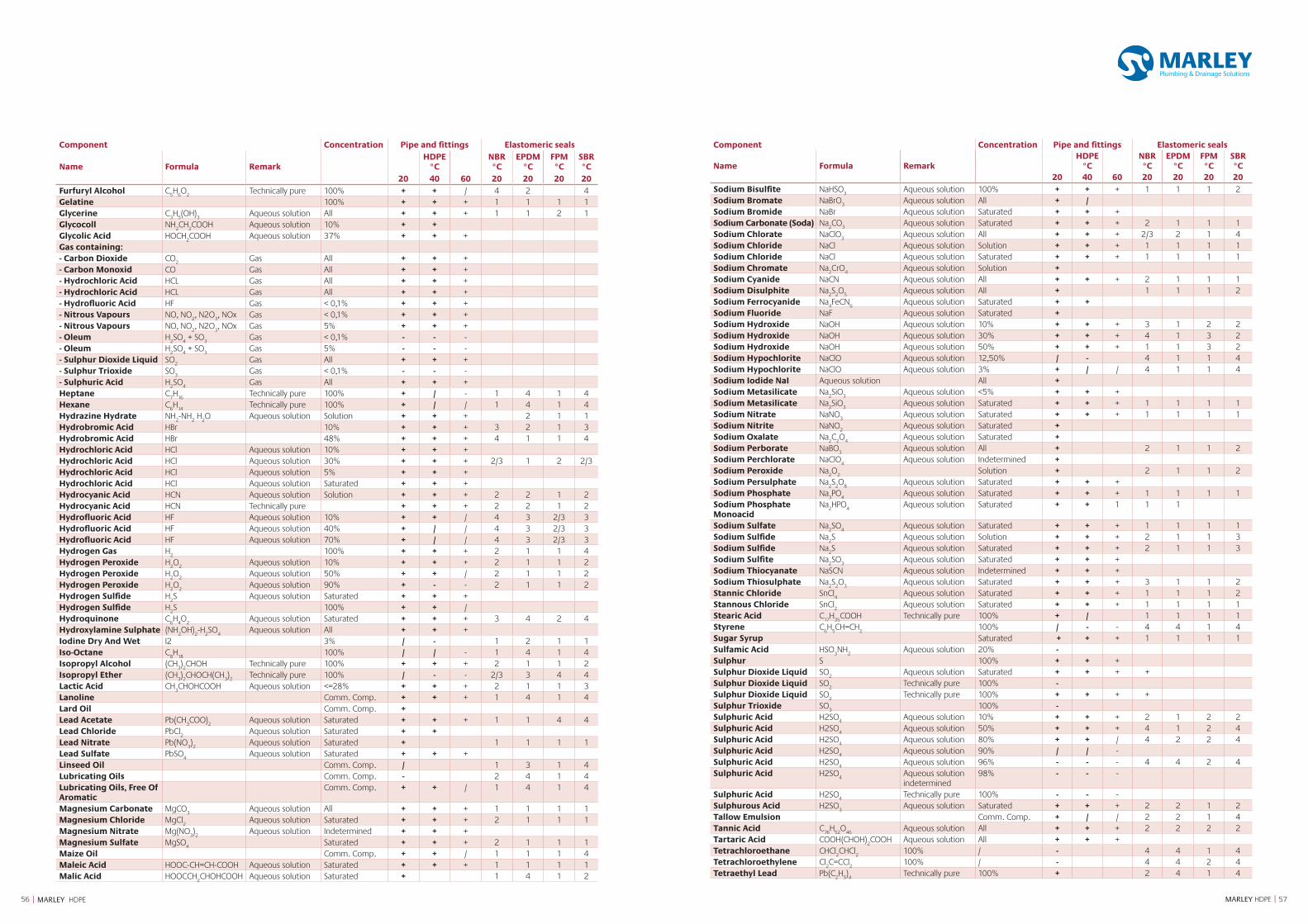
5756 MARLEY HDPE || MARLEY HDPE
Component Concentration Pipe and fittings Elastomeric seals
Name Formula RemarkHDPE
°CNBR°C
EPDM°C
FPM°C
SBR°C
20 40 60 20 20 20 20Furfuryl Alcohol C
5H
6O
2Technically pure 100% + + / 4 2 4
Gelatine 100% + + + 1 1 1 1Glycerine C
3H
5(OH)
3Aqueous solution All + + + 1 1 2 1
Glycocoll NH2CH
2COOH Aqueous solution 10% + +
Glycolic Acid HOCH2COOH Aqueous solution 37% + + +
Gas containing:- Carbon Dioxide CO
2Gas All + + +
- Carbon Monoxid CO Gas All + + +- Hydrochloric Acid HCL Gas All + + +- Hydrochloric Acid HCL Gas All + + +- Hydrofluoric Acid HF Gas < 0,1% + + +- Nitrous Vapours NO, NO
2, N2O
3, NOx Gas < 0,1% + + +
- Nitrous Vapours NO, NO2, N2O
3, NOx Gas 5% + + +
- Oleum H2SO
4 + SO
3Gas < 0,1% - - -
- Oleum H2SO
4 + SO
3Gas 5% - - -
- Sulphur Dioxide Liquid SO2
Gas All + + +- Sulphur Trioxide SO
3Gas < 0,1% - - -
- Sulphuric Acid H2SO
4Gas All + + +
Heptane C7H
16Technically pure 100% + / - 1 4 1 4
Hexane C6H
14Technically pure 100% + / / 1 4 1 4
Hydrazine Hydrate NH2-NH
2 H
2O Aqueous solution Solution + + + 2 1 1
Hydrobromic Acid HBr 10% + + + 3 2 1 3Hydrobromic Acid HBr 48% + + + 4 1 1 4Hydrochloric Acid HCl Aqueous solution 10% + + +Hydrochloric Acid HCl Aqueous solution 30% + + + 2/3 1 2 2/3Hydrochloric Acid HCl Aqueous solution 5% + + +Hydrochloric Acid HCl Aqueous solution Saturated + + +Hydrocyanic Acid HCN Aqueous solution Solution + + + 2 2 1 2Hydrocyanic Acid HCN Technically pure + + + 2 2 1 2Hydrofluoric Acid HF Aqueous solution 10% + + / 4 3 2/3 3Hydrofluoric Acid HF Aqueous solution 40% + / / 4 3 2/3 3Hydrofluoric Acid HF Aqueous solution 70% + / / 4 3 2/3 3Hydrogen Gas H
2100% + + + 2 1 1 4
Hydrogen Peroxide H2O
2Aqueous solution 10% + + + 2 1 1 2
Hydrogen Peroxide H2O
2Aqueous solution 50% + + / 2 1 1 2
Hydrogen Peroxide H2O
2Aqueous solution 90% + - - 2 1 1 2
Hydrogen Sulfide H2S Aqueous solution Saturated + + +
Hydrogen Sulfide H2S 100% + + /
Hydroquinone C6H
4O
2Aqueous solution Saturated + + + 3 4 2 4
Hydroxylamine Sulphate (NH2OH)
2-H
2SO
4Aqueous solution All + + +
Iodine Dry And Wet I2 3% / - 1 2 1 1Iso-Octane C
8H
18100% / / - 1 4 1 4
Isopropyl Alcohol (CH3)2CHOH Technically pure 100% + + + 2 1 1 2
Isopropyl Ether (CH3)2CHOCH(CH
3)2
Technically pure 100% / - - 2/3 3 4 4Lactic Acid CH
3CHOHCOOH Aqueous solution <=28% + + + 2 1 1 3
Lanoline Comm. Comp. + + + 1 4 1 4Lard Oil Comm. Comp. +Lead Acetate Pb(CH
3COO)
2Aqueous solution Saturated + + + 1 1 4 4
Lead Chloride PbCl2
Aqueous solution Saturated + +Lead Nitrate Pb(NO
3)2
Aqueous solution Saturated + 1 1 1 1Lead Sulfate PbSO
4Aqueous solution Saturated + + +
Linseed Oil Comm. Comp. / 1 3 1 4Lubricating Oils Comm. Comp. - 2 4 1 4Lubricating Oils, Free Of Aromatic
Comm. Comp. + + / 1 4 1 4
Magnesium Carbonate MgCO3
Aqueous solution All + + + 1 1 1 1Magnesium Chloride MgCl
2Aqueous solution Saturated + + + 2 1 1 1
Magnesium Nitrate Mg(NO3)2
Aqueous solution Indetermined + + +Magnesium Sulfate MgSO
4Saturated + + + 2 1 1 1
Maize Oil Comm. Comp. + + / 1 1 1 4Maleic Acid HOOC-CH=CH-COOH Aqueous solution Saturated + + + 1 1 1 1Malic Acid HOOCCH
2CHOHCOOH Aqueous solution Saturated + 1 4 1 2
Component Concentration Pipe and fittings Elastomeric seals
Name Formula RemarkHDPE
°CNBR°C
EPDM°C
FPM°C
SBR°C
20 40 60 20 20 20 20Sodium Bisulfite NaHSO
3Aqueous solution 100% + + + 1 1 1 2
Sodium Bromate NaBrO3
Aqueous solution All + /Sodium Bromide NaBr Aqueous solution Saturated + + +Sodium Carbonate (Soda) Na
2CO
3Aqueous solution Saturated + + + 2 1 1 1
Sodium Chlorate NaClO3
Aqueous solution All + + + 2/3 2 1 4Sodium Chloride NaCl Aqueous solution Solution + + + 1 1 1 1Sodium Chloride NaCl Aqueous solution Saturated + + + 1 1 1 1Sodium Chromate Na
2CrO
4Aqueous solution Solution +
Sodium Cyanide NaCN Aqueous solution All + + + 2 1 1 1Sodium Disulphite Na
2S
2O
5Aqueous solution All + 1 1 1 2
Sodium Ferrocyanide Na4FeCN
6Aqueous solution Saturated + +
Sodium Fluoride NaF Aqueous solution Saturated +Sodium Hydroxide NaOH Aqueous solution 10% + + + 3 1 2 2Sodium Hydroxide NaOH Aqueous solution 30% + + + 4 1 3 2Sodium Hydroxide NaOH Aqueous solution 50% + + + 1 1 3 2Sodium Hypochlorite NaClO Aqueous solution 12,50% / - 4 1 1 4Sodium Hypochlorite NaClO Aqueous solution 3% + / / 4 1 1 4Sodium Iodide NaI Aqueous solution All +Sodium Metasilicate Na
2SiO
3Aqueous solution <5% + + +
Sodium Metasilicate Na2SiO
3Aqueous solution Saturated + + + 1 1 1 1
Sodium Nitrate NaNO3
Aqueous solution Saturated + + + 1 1 1 1Sodium Nitrite NaNO
2Aqueous solution Saturated +
Sodium Oxalate Na2C
2O
4Aqueous solution Saturated +
Sodium Perborate NaBO3
Aqueous solution All + 2 1 1 2Sodium Perchlorate NaClO
4Aqueous solution Indetermined +
Sodium Peroxide Na2O
2Solution + 2 1 1 2
Sodium Persulphate Na2S
2O
8Aqueous solution Saturated + + +
Sodium Phosphate Na3PO
4Aqueous solution Saturated + + + 1 1 1 1
Sodium Phosphate Monoacid
Na2HPO
4Aqueous solution Saturated + + 1 1 1
Sodium Sulfate Na2SO
4Aqueous solution Saturated + + + 1 1 1 1
Sodium Sulfide Na2S Aqueous solution Solution + + + 2 1 1 3
Sodium Sulfide Na2S Aqueous solution Saturated + + + 2 1 1 3
Sodium Sulfite Na2SO
3Aqueous solution Saturated + + +
Sodium Thiocyanate NaSCN Aqueous solution Indetermined + + +Sodium Thiosulphate Na
2S
2O
3Aqueous solution Saturated + + + 3 1 1 2
Stannic Chloride SnCl4
Aqueous solution Saturated + + + 1 1 1 2Stannous Chloride SnCl
2Aqueous solution Saturated + + + 1 1 1 1
Stearic Acid C17
H35
COOH Technically pure 100% + / 1 1 1 1Styrene C
6H
5CH=CH
2100% / - - 4 4 1 4
Sugar Syrup Saturated + + + 1 1 1 1Sulfamic Acid HSO
3NH
2Aqueous solution 20% -
Sulphur S 100% + + +Sulphur Dioxide Liquid SO
2Aqueous solution Saturated + + + +
Sulphur Dioxide Liquid SO2
Technically pure 100% -Sulphur Dioxide Liquid SO
2Technically pure 100% + + + +
Sulphur Trioxide SO3
100% -Sulphuric Acid H2SO
4Aqueous solution 10% + + + 2 1 2 2
Sulphuric Acid H2SO4
Aqueous solution 50% + + + 4 1 2 4Sulphuric Acid H2SO
4Aqueous solution 80% + + / 4 2 2 4
Sulphuric Acid H2SO4
Aqueous solution 90% / / -Sulphuric Acid H2SO
4Aqueous solution 96% - - - 4 4 2 4
Sulphuric Acid H2SO4
Aqueous solution indetermined
98% - - -
Sulphuric Acid H2SO4
Technically pure 100% - - -Sulphurous Acid H2SO
3Aqueous solution Saturated + + + 2 2 1 2
Tallow Emulsion Comm. Comp. + / / 2 2 1 4Tannic Acid C
76H
52O
46Aqueous solution All + + + 2 2 2 2
Tartaric Acid COOH(CHOH)2COOH Aqueous solution All + + +
Tetrachloroethane CHCl2CHCl
2100% / - 4 4 1 4
Tetrachloroethylene Cl2C=CCl
2100% / - 4 4 2 4
Tetraethyl Lead Pb(C2H
5)4
Technically pure 100% + 2 4 1 4
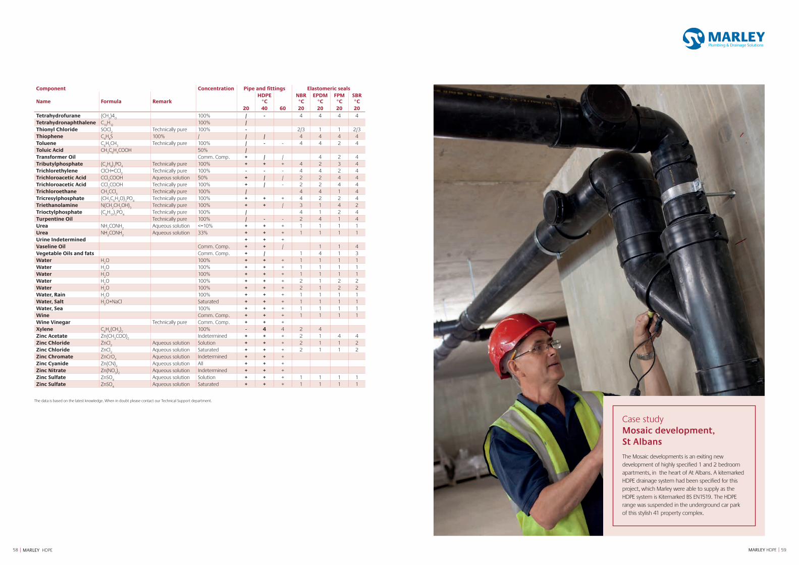
5958 MARLEY HDPE || MARLEY HDPE
Component Concentration Pipe and fittings Elastomeric seals
Name Formula RemarkHDPE
°CNBR°C
EPDM°C
FPM°C
SBR°C
20 40 60 20 20 20 20Tetrahydrofurane (CH
2)4
O100% / - 4 4 4 4
Tetrahydronaphthalene C10
H12
100% /Thionyl Chloride SOCl
2Technically pure 100% - 2/3 1 1 2/3
Thiophene C4H
8S 100% / / / 4 4 4 4
Toluene C6H
5CH
3Technically pure 100% / - - 4 4 2 4
Toluic Acid CH3C
6H
4COOH 50% /
Transformer Oil Comm. Comp. + / / 4 2 4Tributylphosphate (C
4H
9)3PO
4Technically pure 100% + + + 4 2 3 4
Trichlorethylene ClCH=CCl2
Technically pure 100% - - - 4 4 2 4Trichloroacetic Acid CCl
3COOH Aqueous solution 50% + / / 2 2 4 4
Trichloroacetic Acid CCl3COOH Technically pure 100% + / - 2 2 4 4
Trichloroethane CH3CCl
3Technically pure 100% / 4 4 1 4
Tricresylphosphate (CH3C
6H
4O)
3PO
4Technically pure 100% + + + 4 2 2 4
Triethanolamine N(CH2CH
2OH)
3Technically pure 100% + + / 3 1 4 2
Trioctylphosphate (C8H
17)3PO
4Technically pure 100% / 4 1 2 4
Turpentine Oil Technically pure 100% / - - 2 4 1 4Urea NH
2CONH
2Aqueous solution <=10% + + + 1 1 1 1
Urea NH2CONH
2Aqueous solution 33% + + + 1 1 1 1
Urine Indetermined + + +Vaseline Oil Comm. Comp. + + / 1 1 4Vegetable Oils and fats Comm. Comp. + / 1 4 1 3Water H
2O 100% + + + 1 1 1 1
Water H2O 100% + + + 1 1 1 1
Water H2O 100% + + + 1 1 1 1
Water H2O 100% + + + 2 1 2 2
Water H2O 100% + + + 2 1 2 2
Water, Rain H2O 100% + + + 1 1 1 1
Water, Salt H2O+NaCl Saturated + + + 1 1 1 1
Water, Sea 100% + + + 1 1 1 1Wine Comm. Comp. + + + 1 1 1 1Wine Vinegar Technically pure Comm. Comp. + + +Xylene C
6H
4(CH
3)2
100% - 4 4 2 4Zinc Acetate Zn(CH
3COO)
2Indetermined + + + 2 1 4 4
Zinc Chloride ZnCl2
Aqueous solution Solution + + + 2 1 1 2Zinc Chloride ZnCl
2Aqueous solution Saturated + + + 2 1 1 2
Zinc Chromate ZnCrO4
Aqueous solution Indetermined + + +Zinc Cyanide Zn(CN)
2Aqueous solution All + + +
Zinc Nitrate Zn(NO3)2
Aqueous solution Indetermined + + +Zinc Sulfate ZnSO
4Aqueous solution Solution + + + 1 1 1 1
Zinc Sulfate ZnSO4
Aqueous solution Saturated + + + 1 1 1 1
The data is based on the latest knowledge. When in doubt please contact our Technical Support department.
Case study Mosaic development, St Albans
The Mosaic developments is an exiting new development of highly specified 1 and 2 bedroom apartments, in the heart of At Albans. A kitemarked HDPE drainage system had been specified for this project, which Marley were able to supply as the HDPE system is Kitemarked BS EN1519. The HDPE range was suspended in the underground car park of this stylish 41 property complex.
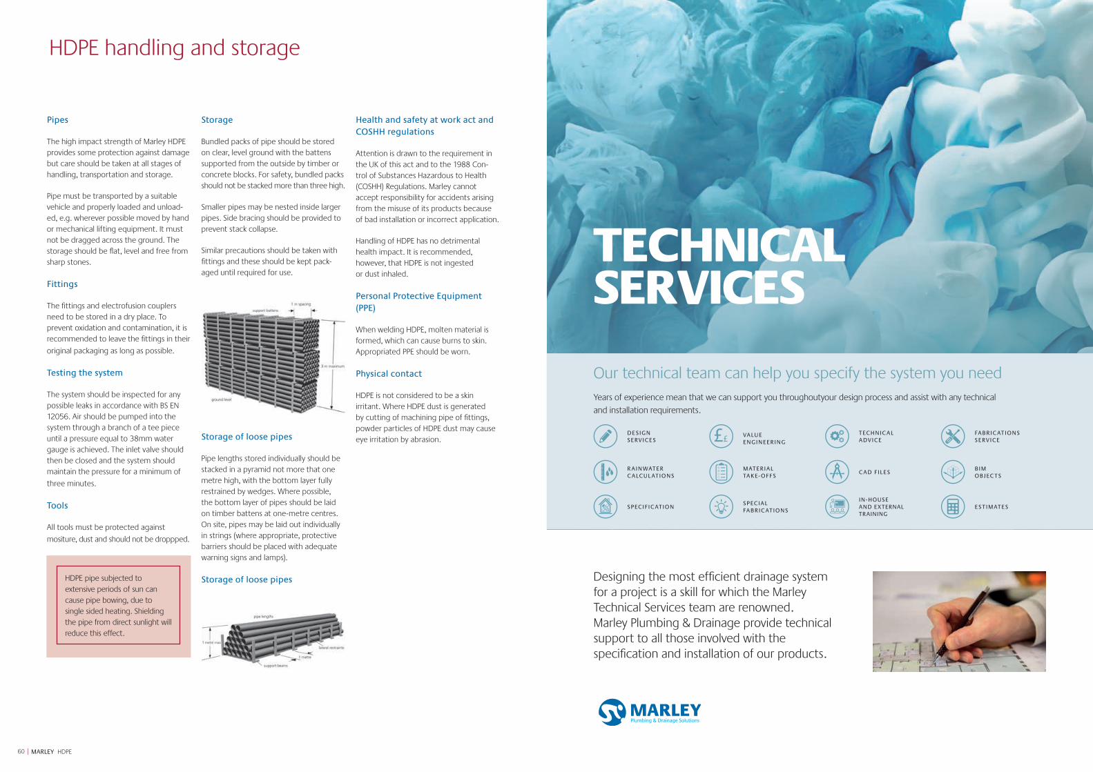
60 | MARLEY HDPE
HDPE handling and storage
Pipes
The high impact strength of Marley HDPE provides some protection against damage but care should be taken at all stages of handling, transportation and storage.
Pipe must be transported by a suitable vehicle and properly loaded and unload-ed, e.g. wherever possible moved by hand or mechanical lifting equipment. It must not be dragged across the ground. The storage should be flat, level and free from sharp stones.
Fittings
The fittings and electrofusion couplers need to be stored in a dry place. To prevent oxidation and contamination, it is recommended to leave the fittings in their
original packaging as long as possible.
Testing the system
The system should be inspected for any possible leaks in accordance with BS EN 12056. Air should be pumped into the system through a branch of a tee piece until a pressure equal to 38mm water gauge is achieved. The inlet valve should then be closed and the system should maintain the pressure for a minimum of
three minutes.
Tools
All tools must be protected against
mositure, dust and should not be droppped.
Storage
Bundled packs of pipe should be stored on clear, level ground with the battens supported from the outside by timber or concrete blocks. For safety, bundled packs should not be stacked more than three high.
Smaller pipes may be nested inside larger pipes. Side bracing should be provided to prevent stack collapse.
Similar precautions should be taken with fittings and these should be kept pack-aged until required for use.
Storage of loose pipes
Pipe lengths stored individually should be stacked in a pyramid not more that one metre high, with the bottom layer fully restrained by wedges. Where possible, the bottom layer of pipes should be laid on timber battens at one-metre centres. On site, pipes may be laid out individually in strings (where appropriate, protective barriers should be placed with adequate warning signs and lamps).
Storage of loose pipes
Health and safety at work act and COSHH regulations
Attention is drawn to the requirement in the UK of this act and to the 1988 Con-trol of Substances Hazardous to Health (COSHH) Regulations. Marley cannot accept responsibility for accidents arising from the misuse of its products because of bad installation or incorrect application.
Handling of HDPE has no detrimental health impact. It is recommended, however, that HDPE is not ingested or dust inhaled.
Personal Protective Equipment (PPE)
When welding HDPE, molten material is formed, which can cause burns to skin. Appropriated PPE should be worn.
Physical contact
HDPE is not considered to be a skin irritant. Where HDPE dust is generated by cutting of machining pipe of fittings, powder particles of HDPE dust may cause eye irritation by abrasion.
HDPE pipe subjected to extensive periods of sun can cause pipe bowing, due to single sided heating. Shielding the pipe from direct sunlight will reduce this effect.
TECHNICAL SERVICES
TECHNICAL SERVICES
Designing the most efficient drainage system for a project is a skill for which the Marley Technical Services team are renowned. Marley Plumbing & Drainage provide technical support to all those involved with the specification and installation of our products.
Our technical team can help you specify the system you needYears of experience mean that we can support you throughoutyour design process and assist with any technical
and installation requirements.
DESIGN SERVICES
VALUE ENGINEERING
TECHNIC AL ADVICE
FABRIC ATIONS SERVICE
R AINWATER C ALCUL ATIONS
MATERIAL TAKE- OFFS
C AD FILESBIM OBJEC TS
SPECIFIC ATIONSPECIAL FABRIC ATIONS
IN-HOUSE AND EXTERNAL TRAINING
ESTIMATES
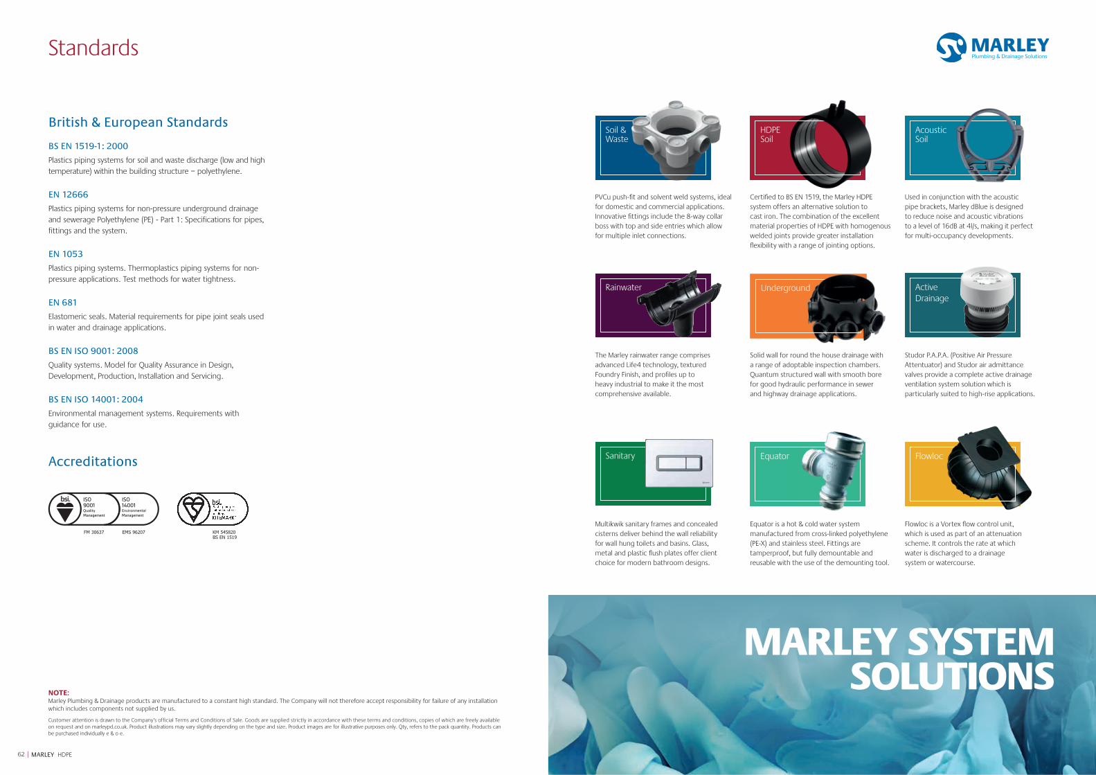
62 | MARLEY HDPE
Standards
British & European Standards
BS EN 1519-1: 2000
Plastics piping systems for soil and waste discharge (low and high temperature) within the building structure – polyethylene.
EN 12666
Plastics piping systems for non-pressure underground drainage and sewerage Polyethylene (PE) - Part 1: Specifications for pipes, fittings and the system.
EN 1053
Plastics piping systems. Thermoplastics piping systems for non-pressure applications. Test methods for water tightness.
EN 681
Elastomeric seals. Material requirements for pipe joint seals used in water and drainage applications.
BS EN ISO 9001: 2008
Quality systems. Model for Quality Assurance in Design, Development, Production, Installation and Servicing.
BS EN ISO 14001: 2004
Environmental management systems. Requirements with guidance for use.
NOTE:Marley Plumbing & Drainage products are manufactured to a constant high standard. The Company will not therefore accept responsibility for failure of any installation which includes components not supplied by us.
Customer attention is drawn to the Company’s official Terms and Conditions of Sale. Goods are supplied strictly in accordance with these terms and conditions, copies of which are freely available on request and on marleypd.co.uk. Product illustrations may vary slightly depending on the type and size. Product images are for illustrative purposes only. Qty, refers to the pack quantity. Products can be purchased individually e & o e.
Accreditations
FM 30637 KM 545820EMS 96207BS EN 1519
PVCu push-fit and solvent weld systems, ideal for domestic and commercial applications. Innovative fittings include the 8-way collar boss with top and side entries which allow for multiple inlet connections.
Certified to BS EN 1519, the Marley HDPE system offers an alternative solution to cast iron. The combination of the excellent material properties of HDPE with homogenous welded joints provide greater installation flexibility with a range of jointing options.
Used in conjunction with the acoustic pipe brackets, Marley dBlue is designed to reduce noise and acoustic vibrations to a level of 16dB at 4l/s, making it perfect for multi-occupancy developments.
HDPE Soil
Soil & Waste
Acoustic Soil
The Marley rainwater range comprises advanced Life4 technology, textured Foundry Finish, and profiles up to heavy industrial to make it the most comprehensive available.
Solid wall for round the house drainage with a range of adoptable inspection chambers. Quantum structured wall with smooth bore for good hydraulic performance in sewer and highway drainage applications.
Studor P.A.P.A. (Positive Air Pressure Attentuator) and Studor air admittance valves provide a complete active drainage ventilation system solution which is particularly suited to high-rise applications.
Rainwater ActiveDrainage
Underground
MARLEY SYSTEM SOLUTIONS
Multikwik sanitary frames and concealed cisterns deliver behind the wall reliability for wall hung toilets and basins. Glass, metal and plastic flush plates offer client choice for modern bathroom designs.
Equator is a hot & cold water system manufactured from cross-linked polyethylene (PE-X) and stainless steel. Fittings are tamperproof, but fully demountable and reusable with the use of the demounting tool.
Flowloc is a Vortex flow control unit, which is used as part of an attenuation scheme. It controls the rate at which water is discharged to a drainage system or watercourse.
Sanitary Equator Flowloc

Underground
64 | MARLEY HDPE
JULY 2019
marleypd.co.uk For general enquiries and details of your nearest stockist please call the customer services department: Tel: 01622 852585Email: [email protected]
To place an order
For delivery to England & WalesEmail: [email protected]: 01622 851111For delivery to ScotlandEmail: [email protected]: 01698 810307
For all estimate requestsEmail: [email protected]
For Technical advice please call 01622 852695
Head Office Lenham, Maidstone Kent ME17 2DE Tel: 01622 858888 Fax: 01622 858725
Email: [email protected]
Scotland Birkenshaw Industrial Estate Uddingston, Glasgow G71 5PA Tel: 01698 815231 Fax: 01698 810307
Export Division Lenham, Maidstone Kent ME17 2DE England Tel: +44 (0)1622 858888 Fax: +44 (0)1622 850778
Email: [email protected]