Embed Size (px)
Citation preview
IACSIT International Journal of Engineering and Technology, Vol.2, No.6, December 2010 ISSN: 1793-8236
508
Abstract— The purpose of this paper is to design and
implement a Middle size soccer robot to conform RoboCup MSL league. In this paper we want to describe computational concepts of cognition that were successfully implemented in the domain of soccer playing robots and show the interactions between cognitive concepts, software engineering and real-time application development. Beside a description of the general concepts we will focus on aspects of Mechanical platform, Motion control module, Omni-directional vision module, Front vision module, Image processing and recognition module, Investigated target object positioning and real coordinate reconstruction, Robot path planning, Competition strategies, and Obstacle avoidance. The methods have been tested in the many Robocup competition field middle size robots.
Index Terms—Mobile robot, Machine vision, Omni directional movement, Autonomous Systems, Robot path planning, Object Localization.
I. INTRODUCTION ROBOCUP is an international competition to prompted
robotics and related subject like: Artificial intelligence, Image processing, control, devise design and etc. One of the subjects in Robocup competitions is Soccer. Naturally robotic soccer is an interactive and complex procedure. It might be so idealistic, but some consider a challenge with a real human football team in 2050, as the final goal of robotic soccer. The robots in middle-size league should only use local sensors and local vision. Each team can have a maximum number of six robots.
They can communicate with each other through a central computer via a radio link. The rules in the competition are the same as the international soccer rules as far as they are practical for robots [1].
The Middle Size League team of the ADRO was founded in 2006. In 2007 we ranked 2nd place Middle Size Soccer Robot League in 2nd International Iran-Open Robocup Competitions the Iran-Open is one of the, Asia’s major RoboCup event. At the China-Open RoboCup 2007 as well as at the Iran–Open RoboCup 2007 we ranked 2nd place Middle Size Soccer Robot League, in 2008 we achieved the First Place in the 3rd International Iran-Open Competitions.
S.H.Kasaei is with the Young Researchers Club of Khorasgan Islamic
Azad University (Isfahan), Iran. (Phone: +98 9133048469 e-mail: [email protected], Web page: http:// www.IranAdro.com).
S.M.Kasaei is with the Young Researchers Club of Khorasgan Islamic Azad University (Isfahan), Iran. (Phone: +98 91312624512 e-mail: Mrezamk2005 @Yahoo.com, Web page: http:// www.IranAdro.com).
The basis for our success was the robust and reliable hardware design, well-structured software architecture and efficient algorithms for sensor fusion and behavior generation. Our main research interest is both, the development of learning robots and the development of improved sensor fusion and sensor integration techniques. Among others, several different approaches have been investigated so far:
1) Reinforcement learning to learn intercepting a ball. 2) Reinforcement learning to learn dribbling and Path
Planning. 3) Development of a computational efficient algorithm for
self-localization. 4) Development of estimation procedures for robot and ball
velocity 5) Development of a vision system with an omni directional
vision sensor and a front camera to recognize ball position and find necessary information in field.
In this paper, we will at first describe the general hard- and
software design of the ADRO Robocup Team, (section 2) and after that focus on our scientic approaches in sensor fusion and learning (section 3). Finally, section 4 concludes this paper.
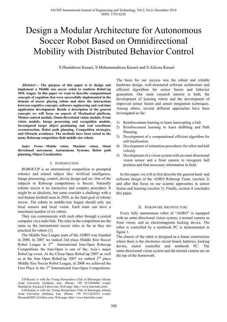
II. HARDWARE ARCHITECTURE Every fully autonomous robot of “ADRO” is equipped
with an omni-directional vision system, a normal camera as front vision, and an electromagnetic kicking device. The robot is controlled by a notebook PC is demonstrated in figure 1. The chassis of the robot is designed as a frame construction where there is the electronic circuit board, batteries, kicking device, motor controller and notebook PC. The omni-directional vision system and the normal camera are on the top of the framework.
S.Hamidreza Kasaei, S.Mohammadreza Kasaei and S.Alireza Kasaei
Design a Modular Architecture for Autonomous Soccer Robot Based on Omnidirectional
Mobility with Distributed Behavior Control
IACSIT International Journal of Engineering and Technology, Vol.2, No.6, December 2010 ISSN: 1793-8236
509
Fig. 1 Our robot is a 3-wheeled omni-directional mobile robot with an
omni-directional vision system, a normal camera and a kicking device, and is controlled by a notebook PC.
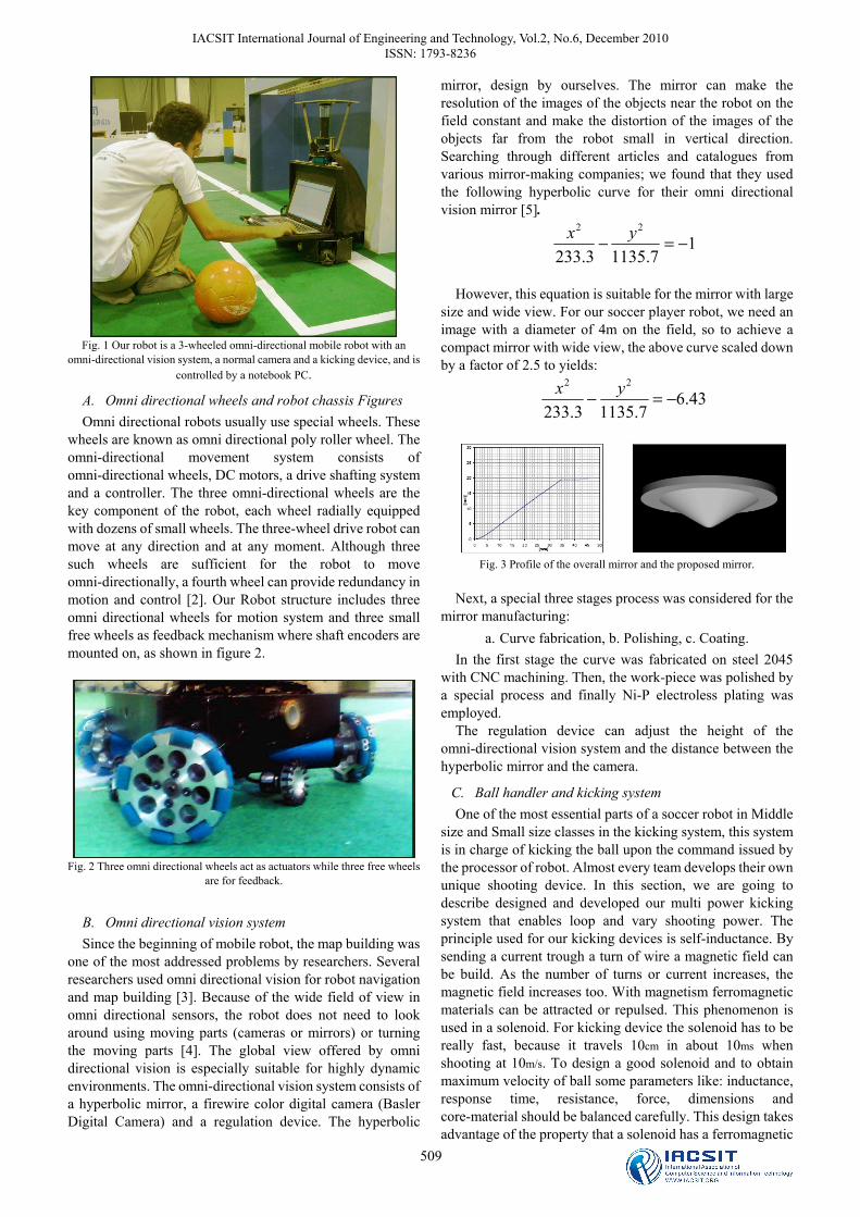
A. Omni directional wheels and robot chassis Figures Omni directional robots usually use special wheels. These
wheels are known as omni directional poly roller wheel. The omni-directional movement system consists of omni-directional wheels, DC motors, a drive shafting system and a controller. The three omni-directional wheels are the key component of the robot, each wheel radially equipped with dozens of small wheels. The three-wheel drive robot can move at any direction and at any moment. Although three such wheels are sufficient for the robot to move omni-directionally, a fourth wheel can provide redundancy in motion and control [2]. Our Robot structure includes three omni directional wheels for motion system and three small free wheels as feedback mechanism where shaft encoders are mounted on, as shown in figure 2.
Fig. 2 Three omni directional wheels act as actuators while three free wheels
are for feedback.
B. Omni directional vision system Since the beginning of mobile robot, the map building was
one of the most addressed problems by researchers. Several researchers used omni directional vision for robot navigation and map building [3]. Because of the wide field of view in omni directional sensors, the robot does not need to look around using moving parts (cameras or mirrors) or turning the moving parts [4]. The global view offered by omni directional vision is especially suitable for highly dynamic environments. The omni-directional vision system consists of a hyperbolic mirror, a firewire color digital camera (Basler Digital Camera) and a regulation device. The hyperbolic
mirror, design by ourselves. The mirror can make the resolution of the images of the objects near the robot on the field constant and make the distortion of the images of the objects far from the robot small in vertical direction. Searching through different articles and catalogues from various mirror-making companies; we found that they used the following hyperbolic curve for their omni directional vision mirror [5].
17.11353.233
22
−=− yx
However, this equation is suitable for the mirror with large
size and wide view. For our soccer player robot, we need an image with a diameter of 4m on the field, so to achieve a compact mirror with wide view, the above curve scaled down by a factor of 2.5 to yields:
43.67.11353.233
22
−=− yx
Fig. 3 Profile of the overall mirror and the proposed mirror.
Next, a special three stages process was considered for the
mirror manufacturing: a. Curve fabrication, b. Polishing, c. Coating.
In the first stage the curve was fabricated on steel 2045 with CNC machining. Then, the work-piece was polished by a special process and finally Ni-P electroless plating was employed.
The regulation device can adjust the height of the omni-directional vision system and the distance between the hyperbolic mirror and the camera.
C. Ball handler and kicking system One of the most essential parts of a soccer robot in Middle
size and Small size classes in the kicking system, this system is in charge of kicking the ball upon the command issued by the processor of robot. Almost every team develops their own unique shooting device. In this section, we are going to describe designed and developed our multi power kicking system that enables loop and vary shooting power. The principle used for our kicking devices is self-inductance. By sending a current trough a turn of wire a magnetic field can be build. As the number of turns or current increases, the magnetic field increases too. With magnetism ferromagnetic materials can be attracted or repulsed. This phenomenon is used in a solenoid. For kicking device the solenoid has to be really fast, because it travels 10cm in about 10ms when shooting at 10m/s. To design a good solenoid and to obtain maximum velocity of ball some parameters like: inductance, response time, resistance, force, dimensions and core-material should be balanced carefully. This design takes advantage of the property that a solenoid has a ferromagnetic
IACSIT International Journal of Engineering and Technology, Vol.2, No.6, December 2010 ISSN: 1793-8236
510
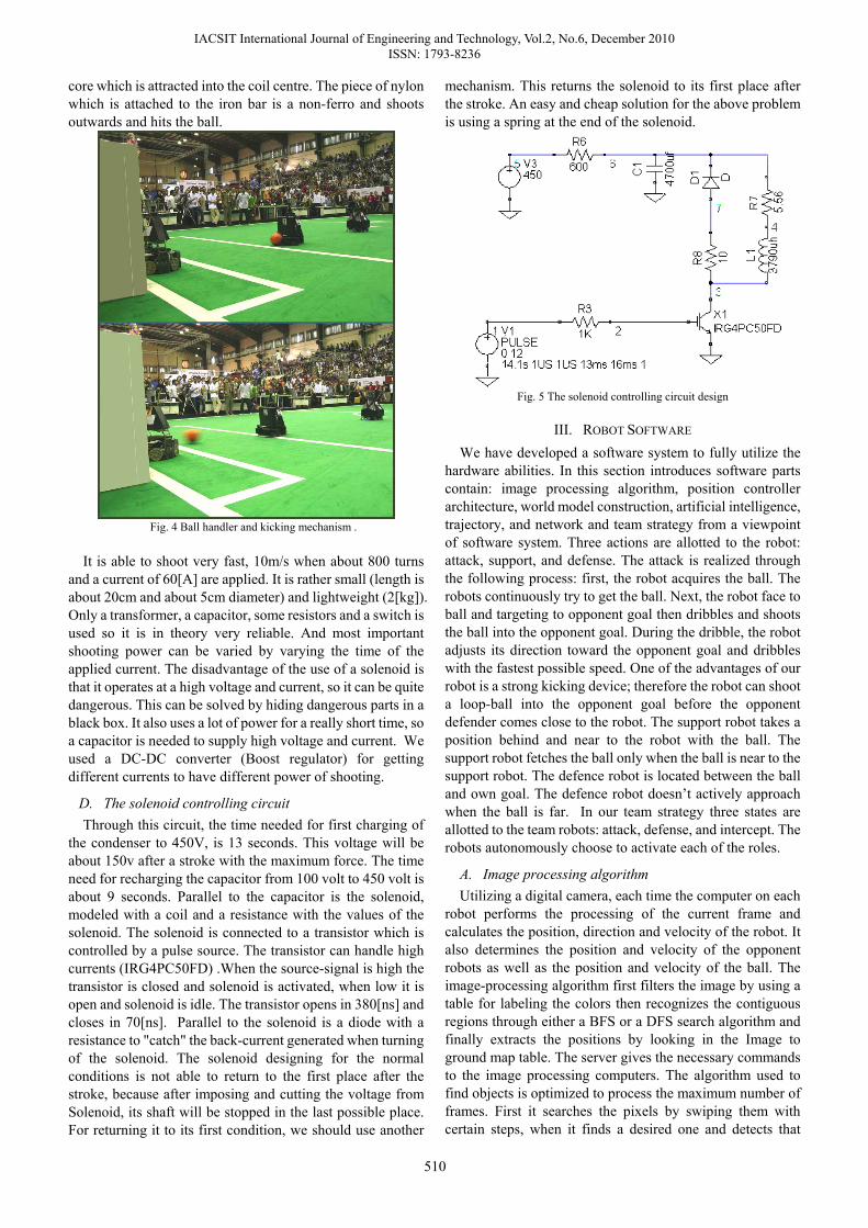
core which is attracted into the coil centre. The piece of nylon which is attached to the iron bar is a non-ferro and shoots outwards and hits the ball.
Fig. 4 Ball handler and kicking mechanism .
It is able to shoot very fast, 10m/s when about 800 turns
and a current of 60[A] are applied. It is rather small (length is about 20cm and about 5cm diameter) and lightweight (2[kg]). Only a transformer, a capacitor, some resistors and a switch is used so it is in theory very reliable. And most important shooting power can be varied by varying the time of the applied current. The disadvantage of the use of a solenoid is that it operates at a high voltage and current, so it can be quite dangerous. This can be solved by hiding dangerous parts in a black box. It also uses a lot of power for a really short time, so a capacitor is needed to supply high voltage and current. We used a DC-DC converter (Boost regulator) for getting different currents to have different power of shooting.
D. The solenoid controlling circuit Through this circuit, the time needed for first charging of
the condenser to 450V, is 13 seconds. This voltage will be about 150v after a stroke with the maximum force. The time need for recharging the capacitor from 100 volt to 450 volt is about 9 seconds. Parallel to the capacitor is the solenoid, modeled with a coil and a resistance with the values of the solenoid. The solenoid is connected to a transistor which is controlled by a pulse source. The transistor can handle high currents (IRG4PC50FD) .When the source-signal is high the transistor is closed and solenoid is activated, when low it is open and solenoid is idle. The transistor opens in 380[ns] and closes in 70[ns]. Parallel to the solenoid is a diode with a resistance to "catch" the back-current generated when turning of the solenoid. The solenoid designing for the normal conditions is not able to return to the first place after the stroke, because after imposing and cutting the voltage from Solenoid, its shaft will be stopped in the last possible place. For returning it to its first condition, we should use another
mechanism. This returns the solenoid to its first place after the stroke. An easy and cheap solution for the above problem is using a spring at the end of the solenoid.
Fig. 5 The solenoid controlling circuit design
III. ROBOT SOFTWARE We have developed a software system to fully utilize the
hardware abilities. In this section introduces software parts contain: image processing algorithm, position controller architecture, world model construction, artificial intelligence, trajectory, and network and team strategy from a viewpoint of software system. Three actions are allotted to the robot: attack, support, and defense. The attack is realized through the following process: first, the robot acquires the ball. The robots continuously try to get the ball. Next, the robot face to ball and targeting to opponent goal then dribbles and shoots the ball into the opponent goal. During the dribble, the robot adjusts its direction toward the opponent goal and dribbles with the fastest possible speed. One of the advantages of our robot is a strong kicking device; therefore the robot can shoot a loop-ball into the opponent goal before the opponent defender comes close to the robot. The support robot takes a position behind and near to the robot with the ball. The support robot fetches the ball only when the ball is near to the support robot. The defence robot is located between the ball and own goal. The defence robot doesn’t actively approach when the ball is far. In our team strategy three states are allotted to the team robots: attack, defense, and intercept. The robots autonomously choose to activate each of the roles.
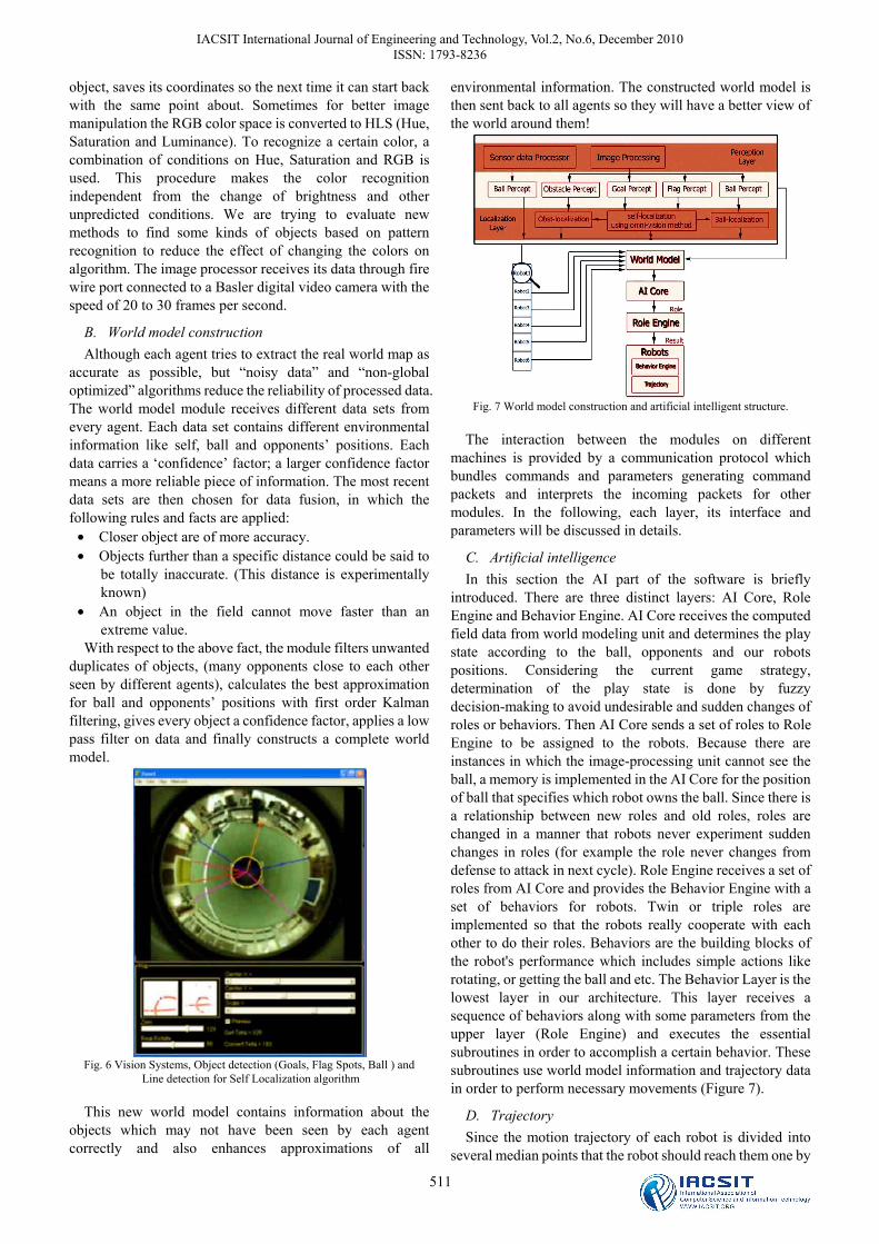
A. Image processing algorithm Utilizing a digital camera, each time the computer on each
robot performs the processing of the current frame and calculates the position, direction and velocity of the robot. It also determines the position and velocity of the opponent robots as well as the position and velocity of the ball. The image-processing algorithm first filters the image by using a table for labeling the colors then recognizes the contiguous regions through either a BFS or a DFS search algorithm and finally extracts the positions by looking in the Image to ground map table. The server gives the necessary commands to the image processing computers. The algorithm used to find objects is optimized to process the maximum number of frames. First it searches the pixels by swiping them with certain steps, when it finds a desired one and detects that
IACSIT International Journal of Engineering and Technology, Vol.2, No.6, December 2010 ISSN: 1793-8236
511
object, saves its coordinates so the next time it can start back with the same point about. Sometimes for better image manipulation the RGB color space is converted to HLS (Hue, Saturation and Luminance). To recognize a certain color, a combination of conditions on Hue, Saturation and RGB is used. This procedure makes the color recognition independent from the change of brightness and other unpredicted conditions. We are trying to evaluate new methods to find some kinds of objects based on pattern recognition to reduce the effect of changing the colors on algorithm. The image processor receives its data through fire wire port connected to a Basler digital video camera with the speed of 20 to 30 frames per second.
B. World model construction Although each agent tries to extract the real world map as
accurate as possible, but “noisy data” and “non-global optimized” algorithms reduce the reliability of processed data. The world model module receives different data sets from every agent. Each data set contains different environmental information like self, ball and opponents’ positions. Each data carries a ‘confidence’ factor; a larger confidence factor means a more reliable piece of information. The most recent data sets are then chosen for data fusion, in which the following rules and facts are applied:
• Closer object are of more accuracy. • Objects further than a specific distance could be said to
be totally inaccurate. (This distance is experimentally known)
• An object in the field cannot move faster than an extreme value.
With respect to the above fact, the module filters unwanted duplicates of objects, (many opponents close to each other seen by different agents), calculates the best approximation for ball and opponents’ positions with first order Kalman filtering, gives every object a confidence factor, applies a low pass filter on data and finally constructs a complete world model.
Fig. 6 Vision Systems, Object detection (Goals, Flag Spots, Ball ) and
Line detection for Self Localization algorithm
This new world model contains information about the objects which may not have been seen by each agent correctly and also enhances approximations of all
environmental information. The constructed world model is then sent back to all agents so they will have a better view of the world around them!
Fig. 7 World model construction and artificial intelligent structure.
The interaction between the modules on different
machines is provided by a communication protocol which bundles commands and parameters generating command packets and interprets the incoming packets for other modules. In the following, each layer, its interface and parameters will be discussed in details.
C. Artificial intelligence In this section the AI part of the software is briefly
introduced. There are three distinct layers: AI Core, Role Engine and Behavior Engine. AI Core receives the computed field data from world modeling unit and determines the play state according to the ball, opponents and our robots positions. Considering the current game strategy, determination of the play state is done by fuzzy decision-making to avoid undesirable and sudden changes of roles or behaviors. Then AI Core sends a set of roles to Role Engine to be assigned to the robots. Because there are instances in which the image-processing unit cannot see the ball, a memory is implemented in the AI Core for the position of ball that specifies which robot owns the ball. Since there is a relationship between new roles and old roles, roles are changed in a manner that robots never experiment sudden changes in roles (for example the role never changes from defense to attack in next cycle). Role Engine receives a set of roles from AI Core and provides the Behavior Engine with a set of behaviors for robots. Twin or triple roles are implemented so that the robots really cooperate with each other to do their roles. Behaviors are the building blocks of the robot's performance which includes simple actions like rotating, or getting the ball and etc. The Behavior Layer is the lowest layer in our architecture. This layer receives a sequence of behaviors along with some parameters from the upper layer (Role Engine) and executes the essential subroutines in order to accomplish a certain behavior. These subroutines use world model information and trajectory data in order to perform necessary movements (Figure 7).
D. Trajectory Since the motion trajectory of each robot is divided into
several median points that the robot should reach them one by
IACSIT International Journal of Engineering and Technology, Vol.2, No.6, December 2010 ISSN: 1793-8236
512
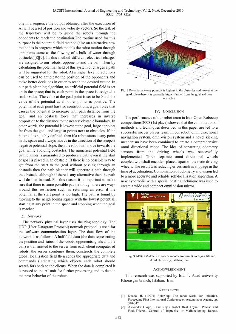
one in a sequence the output obtained after the execution of AI will be a set of position and velocity vectors. So the task of the trajectory will be to guide the robots through the opponents to reach the destination.The routine used for this purpose is the potential field method (also an alternative new method is in progress which models the robot motion through opponents same as the flowing of a bulk of water through obstacles)[8][9]. In this method different electrical charges are assigned to our robots, opponents and the ball. Then by calculating the potential field of this system of charges a path will be suggested for the robot. At a higher level, predictions can be used to anticipate the position of the opponents and make better decisions in order to reach the desired vector. In our path planning algorithm, an artificial potential field is set up in the space; that is, each point in the space is assigned a scalar value. The value at the goal point is set to be 0 and the value of the potential at all other points is positive. The potential at each point has two contributions: a goal force that causes the potential to increase with path distance from the goal, and an obstacle force that increases in inverse proportion to the distance to the nearest obstacle boundary. In other words, the potential is lowest at the goal, large at points far from the goal, and large at points next to obstacles. If the potential is suitably defined, then if a robot starts at any point in the space and always moves in the direction of the steepest negative potential slope, then the robot will move towards the goal while avoiding obstacles. The numerical potential field path planner is guaranteed to produce a path even if the start or goal is placed in an obstacle. If there is no possible way to get from the start to the goal without passing through an obstacle then the path planner will generate a path through the obstacle, although if there is any alternative then the path will do that instead. For this reason it is important to make sure that there is some possible path, although there are ways around this restriction such as returning an error if the potential at the start point is too high. The path is found by moving to the neigh boring square with the lowest potential, starting at any point in the space and stopping when the goal is reached.
E. Network The network physical layer uses the ring topology. The
UDP (User Datagram Protocol) network protocol is used for the software communication layer. The data flow of the network is as follows: A half field data (the data representing the position and status of the robots, opponents, goals and the ball) is transmitted to the server from each client computer of robots, the server combines them, constructs the complete global localization field then sends the appropriate data and commands (indicating which objects each robot should search for) back to the clients. When the data is completed it is passed to the AI unit for further processing and to decide the next behavior of the robots.
Fig. 8 Potential at every point; it is highest in the obstacles and lowest at the
goal. Elsewhere it is generally higher farther from the goal and near obstacles.
IV. CONCLUSION The performance of our robot team in Iran-Open Robocup
competitions 2008 (1st place) showed that the combination of methods and techniques described in this paper are led to a successful soccer player team. In our robot, omni directional navigation system, omni-vision system and a novel kicking mechanism have been combined to create a comprehensive omni directional robot. The idea of separating odometry sensors from the driving wheels was successfully implemented. Three separate omni directional wheels coupled with shaft encoders placed apart of the main driving wheels. The result was reducing errors such as slippage in the time of acceleration. Combination of odometry and vision led to a more accurate and reliable self-localization algorithm. A new hyperbolic with a special coating technique was used to create a wide and compact omni vision mirror.
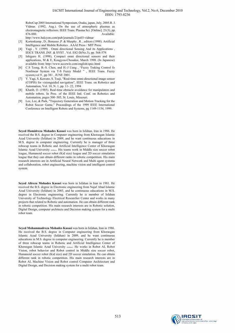
Fig. 9 ADRO Middle size soccer robot team form Khorasgan Islamic
Azad University, Isfahan, Iran
ACKNOWLEDGMENT This research was supported by Islamic Azad university
Khorasgan branch, Isfahan, Iran.
REFERENCES [1] Kitano, H. (1997a) RoboCup: The robot world cup initiative,
Proceeding First International Conference on Autonomous Agents, pp. 340-347
[2] Alexander Gloye, Ra´ul Rojas. Robot Heal Thyself: Precise and Fault-Tolerant Control of Imprecise or Malfunctioning Robots.
IACSIT International Journal of Engineering and Technology, Vol.2, No.6, December 2010 ISSN: 1793-8236
513
RoboCup 2005 International Symposium, Osaka, japan, July, 2005.R. J. Vidmar. (1992, Aug.). On the use of atmospheric plasmas as electromagnetic reflectors. IEEE Trans. Plasma Sci. [Online]. 21(3), pp. 876-880. Available: http://www.halcyon.com/pub/journals/21ps03-vidmar
[3] Kortenkamp , D.; Bonasso ,P. & Murphy , R. , editors (1998). Artificial Intelligence and Mobile Robotics . AAAI Press / MIT Press
[4] Yagi , Y. (1999) . Omni directional Sensing And its Applications , IEICE TRANS ,INF. & SYST . Vol. E82-D(No.3), pp. 568-579.
[5] Ishiguro H. (1998), Compact omni directional sensors and their applications, M & E, Kougyou-Chosakai, March 1998. (In Japanese) available from: http://www.accowle.com/english/spec.html
[6] C.S Tesng, B.-S. Chen, and H.-J Uang , “Fuzzy Traking Control fo Nonlinear System via T-S Fuzzy Model ” , IEEE Trans. Fuzzy sysrem,vol 9 , pp 381 , JUNE 2001.
[7] Y. Yagi, S. Kawato, S. Tsuji, "Real-time omni-directional image sensor (COPIS) for visionguided navigation", IEEE Trans. on Robotics and Automation, Vol. 10, N. 1, pp. 11- 22, 1994
[8] Khatib, O. (1985). Real-time obstacle avoidance for manipulators and mobile robots. In Proc. of the IEEE Intl. Conf. on Robotics and Automation, pages 500–505, St. Louis, Missouri.
[9] Lee, Lee, & Park, "Trajectory Generation and Motion Tracking for the Robot Soccer Game,” Proceedings of the 1999 IEEE International Conference on Intelligent Robots and Systems, pg 1149-1154, 1999.
Seyed Hamidreza Mohades Kasaei was born in Isfahan, Iran in 1986. He received the B.S. degree in Computer engineering from Khorasgan Islamic Azad University (Isfahan) in 2009, and he want continuous educations in M.S. degree in computer engineering. Currently he is manager of three robocup teams in Robotic and Artificial Intelligence Center of Khorasgan Islamic Azad University (Isfahan). His teams work in Middle size soccer robot league, Humanoid soccer robot (Kid size) league and 2D soccer simulation league that they can obtain different ranks in robotic competition. His main research interests are in Artificial Neural Network and Multi agent systems and collaboration, robot engineering, machine vision and intelligent control system. Seyed Alireza Mohades Kasaei was born in Isfahan in Iran in 1981. He received the B.S. degree in Electronic engineering from Najaf Abad Islamic Azad University (Isfahan) in 2003, and he continuous educations in M.S. degree in Electronic engineering. Currently he is member of Isfahan University of Technology Electrical Researcher Center and works in many projects that related to Robotic and automation. He can obtain different rank in robotic competition. His main research interests are in Robotic solution, Digital Design, computer architects and Decision making system for a multi robot team. Seyed Mohammadreza Mohades Kasaei was born in Isfahan, Iran in 1986. He received the B.S. degree in Computer engineering from Khorasgan Islamic Azad University (Isfahan) in 2009, and he want continuous educations in M.S. degree in computer engineering. Currently he is member of three robocup teams in Robotic and Artificial Intelligence Center of Khorasgan Islamic Azad University (Isfahan). He works in Robot AI, Robot Vision, robot behavior and Robot control in Middle size soccer robot, Humanoid soccer robot (Kid size) and 2D soccer simulation. He can obtain different rank in robotic competition. His main research interests are in Robot AI, Machine Vision and Robot control Computer Architecture and Digital Design, and Decision making system for a multi robot team.