Embed Size (px)
Citation preview
.......
( '0
*IR s- -6
IjMA ACTORS ENIERN DESIG .TNR
w~EAN CALULBRARYREFERENCE COPY~
a.1 SpeciliCau' ff ic 'e
Systeis Research Laboratory
Sys eins ~ e 16
Se te l r 19 6L A ~B O -R A T O -R I
HtTMIANFJ~IFRN
?-ROVINGI GIROUND P
ABE IARBYLAND'
Z 0 6 V O O ib t on this doCu m etT I s uiS -iis n-lted

0
Destr6y this report when no longer needed.Do not return it to the originator.
The findings in this report are not to be construed as an official
Department of the Army position unless so designated by other
authorized' doctfhis. •
Use of trade names in this report does not constitute an official
endorsement or approval of the use of such commercial products.

DISCLAIMER NOTICE
THIS DOCUMENT IS BESTQUALITY AVAILABLE. THE COPYFURNISHED TO DTIC CONTAINED
A SIGNIFICANT NUMBER OFPAGES WHICH DO NOTREPRODUCE LEGIBLY.
HEL Standard S-6-660
HUMAN FACTORS ENGINEERING DESIGN STANDARD
FOR WHEELED VEHICLES
"Robert F. ChailletAlfreda R. Honigfeld
0
September 1966
APPROVID:.(L-qOHN D. WEISZ
Technical DirectorHuman Engineering Laboratories
U. S. ARMY HUMAN ENGINEERING LABORATORIESAberdeen Proving Ground, Maryland
Distribution of this document is unlimited.

PROMULGATION SHEET
1. The data contained in this standard reflect the official position of the U. S.Army Human Engineering Laboratories (HEL) and supersede all other data issued bythese laboratories that pertain to the subject of this standard. (Specifically, thisstandard supersedes Technical Memorandum 21-62.)
2. Human Engineering Laboratories standards are issued for use by the majorsubordinate commands of the Army Materiel Command (AMC) in the area of humanfactors engineering, in accordance with AMCR 70-1.
3. HEL standards guide the AMC major subordinate commands and projectmanagers for the inclusion of human factors engineering requirements into researchand development or procurement contractual documents.
4. HEL standards are the basis for the human factors engineering evaluationsthat HEL conducts in accordance with AMCR 10-4.
5. The use of HEL standards does not obviate the need for participation byhuman factors specialists during research, development, test, and evaluation,because neither the areas of interest in this standard nor the contents of these areasis exhaustive.
Iii

CONTROLS
GENERAL . . . . . . . . 66
Considerations in Selecting Controls ......... .... 69
MANIPULATION AND* SEPARATION OF CONTROLS . . . . ... 72
DESIGN CHARACTERISTICS ......................... 73
HAND CRANKS .................... .*. . . 75
HANDWHEELS ........ ........................ . . 77
KEY-OPERATED SWITCH............................. . 79
I(NOBS ..................... ........................... 81
LEVER/JOYSTICK ...................... . 83
PEDALS ................................ .. 85
PUSHBUTTO NS................ . . . . . . . 87
ROTARYSELECTOR SWITCH ..................... 89
TOGGLE SWITCHES ............. 91
DISPLAYS
GENERAL REQUIREMENTS. .................. 92
CRITERIA FOR CHOOSING TYPES OF DISPLAYS . . . . . . . . 95
INDICATOR LIGHTS................. . . . . . . . . . 96
Simple Indicator Lights . . . . . . . . . . . . . . . . . 97
COLOR CODING .. .. .. .. ... . . . ... 98
FCLASH CODING . . . . . ... . . . . . . 98
V
MOVING-POINTER FIXED-SCALE INDICATORS
Circular Scales ....................... . 99
Non-Linear Scales ......... ................... .... 99Pointers ......... .......................... 99
EMERGENCY INDICATIONS ........ .................. .... 101
Auditory Warning Signals ................. 101Visual Warning Signals ...... .................. .... 103
CODING
GENERAL .L................................ . . . . . . 104
CONTROLS
Color ......... ...................... . . . 105Shape .................. .......................... 105Size ................... .......................... 107Location ............ ........................ .... 107
COLOR BANDING OF DISPLAY SCALE ZONES ........... ... 109 0Shape ........... .......................... .... 109Size ................... .......................... 109Location ................. ........................ 110
CONDUCTORS
Electrical Conductors ............ .................. 111Hydraulic and Pneumatic Conductors ................. 111
LABELING
GENERAL .... ........... . . . ............ 113
NUMERAL AND LETTER DESIGN
Style ........ ........................... 114
Height-to-Stroke Width Ratio ..... ................. 114Width ........... .......................... .... 114Spacing and Size ........ ....................... 115
vi
CONTENT . .... ... . .. .. .... .... .. .. . 117
LABELING FOR IDENTIFICATION
Assemblies .......... ......................... 117Connectors ..................................... 117Instruction Plates ............................... 118Lift Points ......... .......................... 119Safety and Hazards ......... ..................... 119
COMMUNICATIONS
GENERAL ........... .......................... .... 120
RADIO SET ............ ......................... .... 121
RADIO ANTENNA ........... ...................... .... 121
CONTROLBOX ......... .......................... 122
AUDIO ACCESSORIES .......... ................... ..... 122
CABLE ROUTING ......... ....................... .... 122
STOWAGE
GENERAL .......... ..................... . ... 123
INTERFERENCE ................. ....................... 124
USE OF STOWAGE SPACE ............. ................... 124
RETAINING ............................. . . 124
STOWAGE BOXES -- DOORS AND COVERS ................ . 125
MAINTENANCE
GENERAL .... ........... . .............. 126
TOOIL.S .............. ........................... .... 128
GENERAL WORK-SPACE REQUIREMENTS ................. 128
vii

GENERAL ACCESS REQUIREMENTS ..... .............. .... 129
ACCESS .................... .......................... 130
Shape of Accesses ............. .................... 131Size of Accesses ........ ..................... .... 131Location of Accesses ........ ................... .... 137
CONNECTORS ............ ....................... .... .. 138
Classification of Connectors ...... ............... .... 141Electrical Connectors ....... .................... 142Fluid and Gas Connectors ............. ................ 143
COVERS AND CASES ............... ..................... 145
FASTENERS ....................................... .... 151
Types of Fasteners ............................. 153
HANDLES ............... ....................... .... 157
HANDLING EQUIPMENT
Jacks ........... .......................... .... 160Cranes ........................................ 160
LINES AND CABLES ............ .................... .... 161
Fluid and Gas Lines ........ ................... .... 163Electrical Wires and Cables ........... ............... 164
MOUNTING AND ARRANGING ............ ................. 166
TEST AND SERVICE POINTS ............. ................. 171
viii

O FIGURES
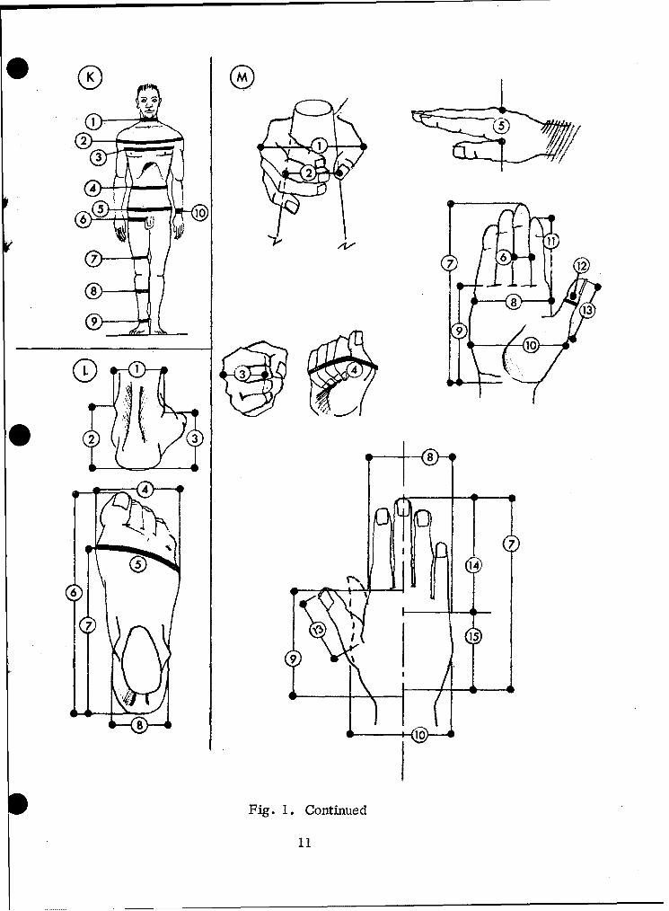
1. Body Dimensions ............. .. . . . . . . 7
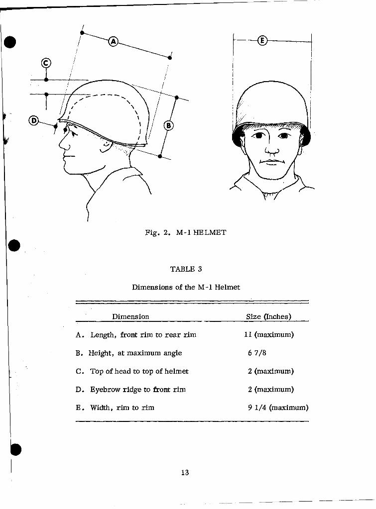
2. M-I Helmet . . . 13
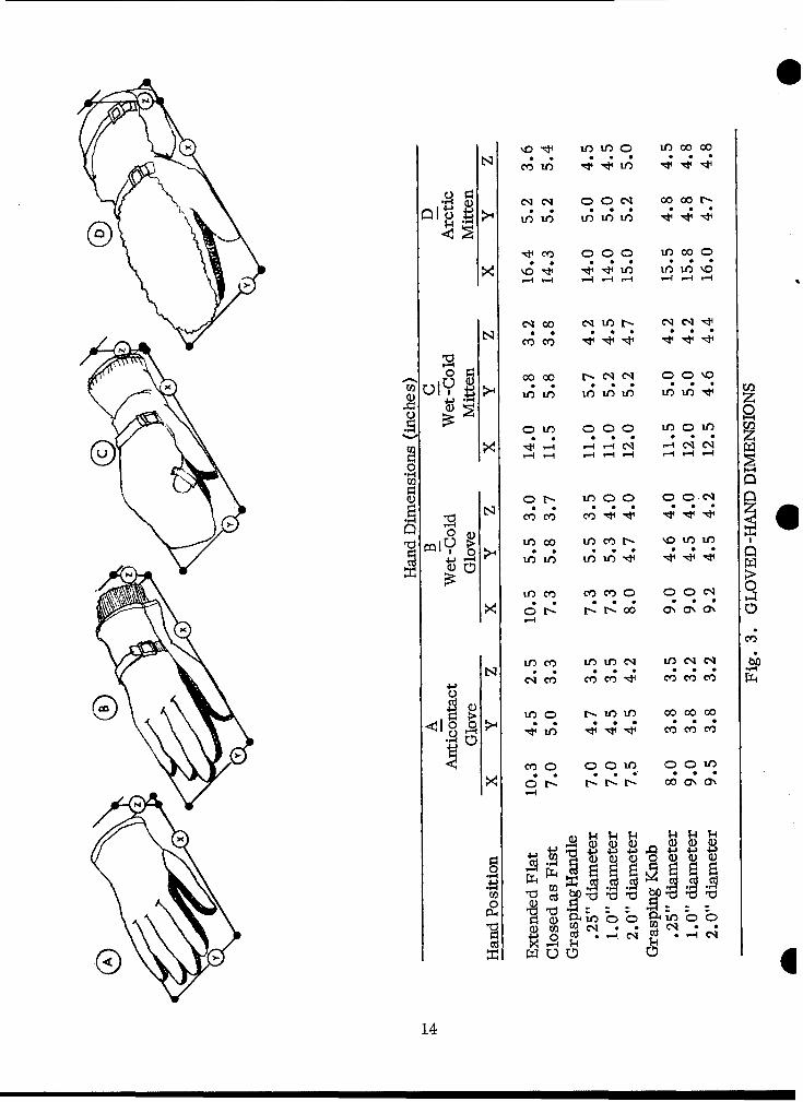
3. Gloved-Hand Dimensions ...... ... . . .. . . . . 14
4. Manual Lifting Capacity ............... . . . . . 16
5. Human Strength ....................... 17
6. Range of Human Motion .......... .......... .21
7. Windchill Chart . . . . . ................. 26
8. Deriving Effective Temperature . .......... . . . 28
9. Person-To-Person Communications..................... . 33
10. Human Reaction to Vertical Vibrations .......... .. 36
11. Incline Angles for the Use of Various Structures . . .... . 58
12. Stair-Ladder Dimensions ........ . . . . . . 59
13. Fixed-Ladder Dimensions ........... 59
14. Dimensions for Vehicle Operator's Seat ...... .............. 62
15. Cranks . . ... ............ . . . .... . 74
16. Handwheels . . . . ...................... 76
17. Key-Operated Switch ................. 78
18. Knobs . . . . . . . ........... . ........ 80
19. Lever/Joystick ............. ........... . 82
20. Pedals........... . . . . . . . .......... . 84
21. Push Buttons . . . . . ............... . ... 86
22. Rotary Selector Switch .................... . . 88
ix
23. Toggle Switches ............. ........... . 90
24. Frequency Characteristics of Auditory Master-Warning Signal . . . 101
25. Coding of Displays . ........... . . . . . . . . . . . 108
26. One-Hand Access Openings ............................... 133
27. Access-Opening Dimensions .......................... 134
28. Covers and Accesses ...... ....................... 136
29. Covers and Cases: Design Examples . . . ........... 144
30. Fastener Examples .......... ......................... 150
31. Minimum Handle Dimensions....................... . 158
TABLES
1. Body Dimensions ......... ........................ 6
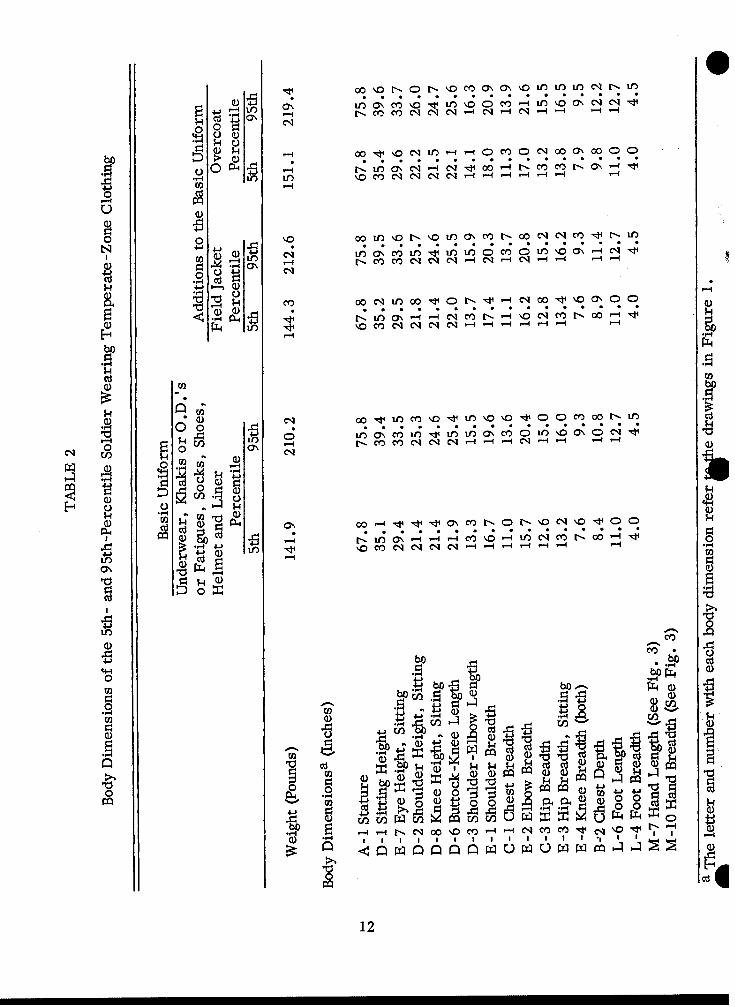
2. Body Dimensions of the 5th- and 95th-Percentile Soldier Wearing 6Temperate-Zone Clothing ......... ..................... 12
3. Dimensions of the M-l Helmet........................ . 13
4. Range of Human Motion ..... ........................ 20
5. Noxious Exhaust Products of Engine Fuels . ........... 30
6. Illumination Requirements for Wheeled Vehicles ... ......... ... 38
7. Illumination Requirements for Representative Tasks. . . . 40
8. Specific-Task Illumination Requirements . . . . ......... 41
9. Brightness Ratios . . . . . . . . . . . . ......... 43
10. Stair-Ladder Dimensions . . . . . . . . . . . . . . . . 59
11. Fixed-Ladder Dimensions .... 59
12. Conventional Control Movements . . . . . . . . . . . . . . . . 66
x

13. Recommended Manual Controls ...... .................... 70
14. Cranks ........ ............ ........ 74
15. Handwheel Dimensions ... . ........................... 76
16. Key-Operatedt-Switch Dimensions ...... ................ o.78
17. Knob Dimensions .......... ....................... ... 80
18. Lever/Joystick o.......... ........................ o .82
19. Pedals ............. ............................. .. 84
20. Push Buttons ............... ......................... 86
21. Rotary Selector Switch ... .. ................. .... o88
22. Toggle Switches .............. ........................ 90
23. Color Codes: Cross Reference ...... ................. .. 106
24. Electrical Cable Coding .......... .................... .. 112
25. Character Height and Viewing Distance .... ............. .. 116
26. One-Hand Access Openings ....... ................... .132
xi

HUMAN FACTORS ENGINEERING DESIGN STANDARD
FOR WHEELED VEHICLES
INTRODUCTION
In order for equipment to be utilized most efficiently, it must be designed forthe specific user population. This constraint upon design is obviously, although per-haps unconsciously, one of the designer's primary considerations.
Designers must design for men who, in tactical situations, will be under con-ditions of stress and fatigue from many causes. A performance decrement may arisein the tactical situation not so much because troops are basically unable to perform,but because the individual soldier is over -loaded, both physically and mentally.
Equipment must be designed so the procedures for using it are as simple as* possible. Equipment should not require intellectual tasks like transforming data
when personnel may be distracted. More complex equipment is likewise undesirable,because it is less reliable and less maintainable.
It is recognized that training can improve crew proficiency; however, trainingshould not be considered a substitute for good design.
As a general comment about the design of Army equipment, more complexweapon systems mean the Army must either find more capable people or designequipment so the people who are available can use it. The latter technique is prefer-able.
It is important to have information about the men who serve as crew members.Their capabilities and limitations are among the basic considerations in designingequipment.
The official Army selection procedures are given in AR 611-201, "Manual ofEnlisted Military Occupational Specialties," and AR 600-200, "Enlisted PersonnelManagement System."
l1

This Standard gives the design engineer both human factors engineering designprinciples and detailed criteria. The design principles are stated as general rulesto be applied during system-development programs or as essential items that mustbe considered during design to insure that sound human factors engineering practiceswill be incorporated. The detailed criteria consist of dimensions, ranges, tolerances,and other specific data. In some cases, the range of acceptable dimensions and otherfactors may be rather large. Where only the minimum and maximum are given,design engineers may select any part or item within the recommended range. Butwhere optimum dimensions are given, designers should aim to approximate themwhenever possible.
2
ANTHROPOMETRICS
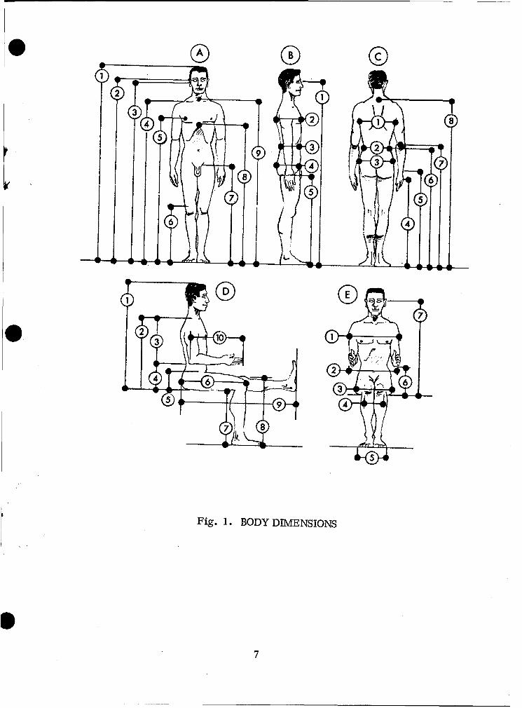
BODY DIMENSIONS
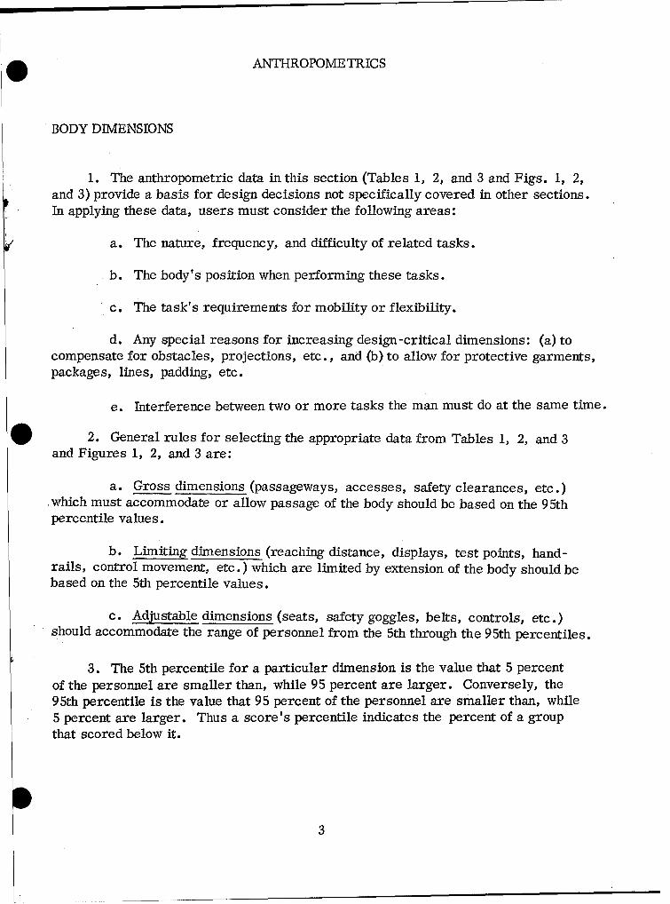
1. The anthropometric data in this section (Tables 1, 2, and 3 and Figs. 1, 2,and 3) provide a basis for design decisions not specifically covered in other sections.In applying these data, users must consider the following areas:
a. The nature, frequency, and difficulty of related tasks.
b. The body's position when performing these tasks.
c. The task's requirements for mobility or flexibility.
d. Any special reasons for increasing design-critical dimensions: (a) tocompensate for obstacles, projections, etc., and (b) to allow for protective garments,packages, lines, padding, etc.
e. Interference between two or more tasks the man must do at the same time.
2. General rules for selecting the appropriate data from Tables 1, 2, and 3and Figures 1, 2, and 3 are:
a. Gross dimensions (passageways, accesses, safety clearances, etc.)which must accommodate or allow passage of the body should be based on the 95thpercentile values.
b. Limiting dimensions (reaching distance, displays, test points, hand-rails, control movement, etc.) which are limited by extension of the body should bebased on the 5th percentile values.
c. Adjustable dimensions (seats, safety goggles, belts, controls, etc.)should accommodate the range of personnel from the 5th through the 95th percentiles.
3. The 5th percentile for a particular dimension is the value that 5 percentof the personnel are smaller than, while 95 percent are larger. Conversely, the95th percentile is the value that 95 percent of the personnel are smaller than, while5 percent are larger. Thus a score's percentile indicates the percent of a groupthat scored below it.
3

4. Probably no individual matches either the 5th or the 95th percentile valuesexactly on all dimensions. For example, an individual may be at the 95th percentilein stature and seated eye -height, but have an arm reach or hand measurement wellbelow the 95th-percentile dimensions.
5. When personnel relax -- slump -- they may reduce their seated eye -heightmeasurements (Fig. 1, E-7) by as much as 2.5 inches. This slump factor must beconsidered in locating displays, in establishing the system's visual requirements,and in selecting a seat's range of adjustment. Note, however, that the slump factoris not a valid reason for lowering ceilings to save space.
6. Anthropometric data in Table 1 are taken on the nude figure. This is toavoid confusions caused by the wide variations in dress. It is necessary to makeallowances for clothing. Table 2 shows increments added by the basic uniform.
I4|
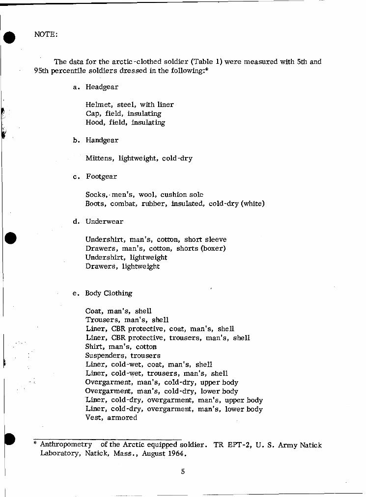
. NOTE:
The data for the arctic -clothed soldier (Table 1) were measured with 5th and95th percentile soldiers dressed in the following:*
a. Headgear
Helmet, steel, with linerCap, field, insulatingHood, field, insulating
b. Handgear
Mittens, lightweight, cold-dry
c. Footgear
Socks, -men's, wool, cushion soleBoots, combat, rubber, insulated, cold-dry (white)
d. Underwear
Undershirt, man's, cotton, short sleeveDrawers, man's, cotton, shorts (boxer)Undershirt, lightweightDrawers, lightweight
e. Body Clothing
Coat, man's, shellTrousers, man's, shellLiner, CBR protective, coat, man's, shellLiner, CBR protective, trousers, man's, shellShirt, man's, cottonSuspenders, trousersLiner, cold-wet, coat, man's, shellLiner, cold-wet, trousers, man's, shellOvergarment, man's, cold-dry, upper bodyOvergarment, man's, cold-dry, lower bodyLiner, cold-dry, overgarment, man's, upper bodyLiner, cold-dry, overgarment, man's, lower bodyVest, armored
* Anthropometry of the Arctic equipped soldier. TR EPT-2, U. S. Army Natick
Laboratory, Natick, Mass., August 1964.
5
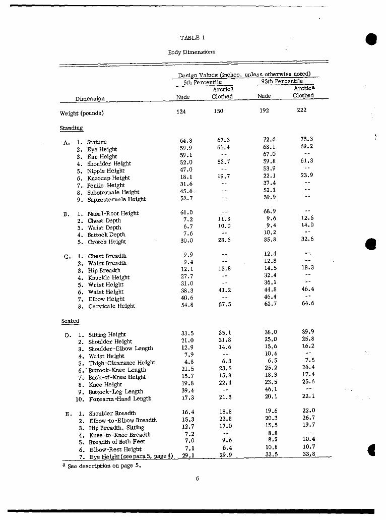
TABLE 1
Body Dimensions
Design Values (inches, unless otherwise noted)5th Percentile 95th Percentile
Arctica Arctica
Dimension Nude Clothed Nude Clothed
Weight (pounds) 124 150 192 222
Standing
A. 1. Stature 64.3 67.3 72.6 75.3
2. Eye Height 59.9 61.4 68.1 69.2
3. Ear Height 59.1 -- 67.0 --
4. Shoulder Height 52.0 53.7 59.8 61.3
5. Nipple Height 47.0 -- 53.9 --
6. Kneecap Height 18.1 19.7 22.1 23.9
7. Penile Height 31.6 -- 37.4 --
8. Substernale Height 45.6, -- 52.1 --
9. Suprasternale Height 52.7 -- 59.9 --
B. 1. Nasal-Root Height 61.0 -- 68.9 --
2. Chest Depth 7.2 11.8 9.6 12.6
3. Waist Depth 6.7 10.0 9.4 14.0
4. Buttock Depth 7.6 -- 10.2 --
5. Crotch Height 30.0 28.6 35.8 32.6
C. 1. Chest Breadth 9.9 -- 12.4
2. Waist Breadth 9.4 -- 12.3 --
3. Hip Breadth 12.1 15.8 14.5 18.3
4. Knuckle Height 27.7 -- 32.4 --
5. Wrist Height 31.0 -- 36.1 --
6. Waist Height 38.3 41.2 44.8 46.4
7. Elbow Height 40.6 -- 46.4 --
8. Cervicale Height 54.8 57.5 62.7 64.6
Seated
D. 1. Sitting Height 33.5 35.1 38.0 39.9
2. Shoulder Height 21.0 21.8 25.0 25.8
3. Shoulder-Elbow Length 12.9 14.6 15.6 16.2
4. Waist Height 7.9 -- 10.4 --
5. Thigh-Clearance Height 4.8 6.3 6.5 7.5
6.' Buttock-Knee Length 21.5 23.5 25.2 26.4
7. Back-of-Knee Height 15.7 15.8 18.3 17.4
8. Knee Height 19.8 22.4 23.5 25.6
9. Buttock-Leg Length 39.4 -- 46.1 --
10. Forearm-Hand Length 17.3 21.3 20.1 22.1
E. 1. Shoulder Breadth 16.4 18.8 19.6 22.0
2. Elbow-to-Elbow Breadth 15.3 22.8 20.3 26.7
3. Hip Breadth, Sitting 12.7 17.0 15.5 19.7
4. Knee-to-Knee Breadth 7.2 -- 8.8 --
5. Breadth of Both Feet 7.0 9.6 8.2 10.4
6. Elbow-Rest Height 7.1 6.4 10.8 10.7
7. Eye Height (see para 5,page 4 ) 29.1 29.9 33.5 33.8
a See description on page 5.
6
3 0
77
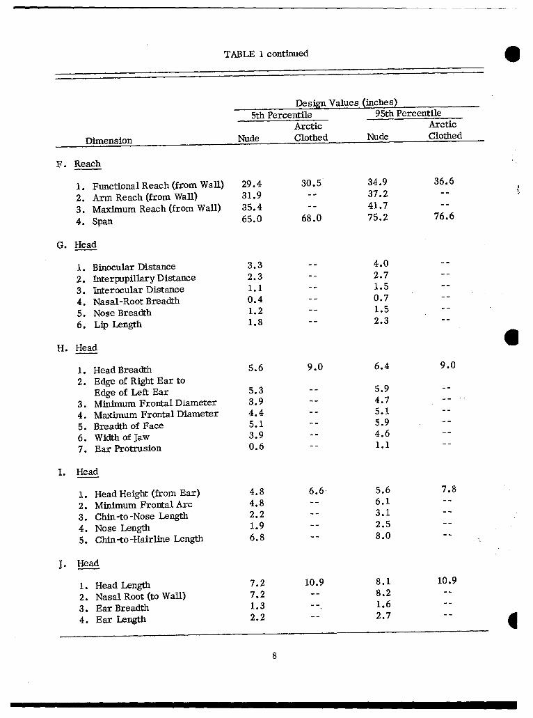
TABLE I continued
Design Values (inches)5th Percentile 95th Percentile
Arctic Arctic
Dimension Nude Clothed Nude Clothed
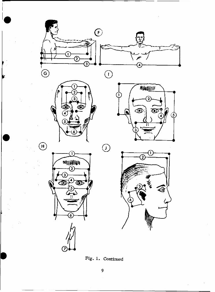
F. Reach
1. Functional Reach (from Wall) 29.4 30.5 34.9 36.6
2. Arm Reach (from Wall) 31.9 -- 37.2 --
3. Maximum Reach (from Wall) 35.4 -- 41.7 --
4. Span 65.0 68.0 75.2 76.6
G. Head
1. Binocular Distance 3.3 -- 4.0 --
2. Interpupillary Distance 2.3 -- 2.7 --
3. Interocular Distance 1.1 -- 1.5 --
4. Nasal-Root Breadth 0.4 -- 0.7 --
5. Nose Breadth 1.2 -- 1.5 --
6. Lip Length 1.8 -- 2.3 --
H. Head 61. Head Breadth 5.6 9.0 6.4 9.0
2. Edge of Right Ear toEdge of Left Ear 5.3 -- 5.9 --
3. Minimum Frontal Diameter 3.9 -- 4.7 --
4. Maximum Frontal Diameter 4.4 -- 5.1 --
5. Breadth of Face 5.1 -- 5.9 --
6. Width of jaw 3.9 -- 4.6 --
7. Ear Protrusion 0.6 -- i.1 --
I. Head
1. Head Height (from Ear) 4.8 6.6 5.6 7.8
2. Minimum Frontal Arc 4.8 -- 6.1 --
3. Chin-to-Nose Length 2.2 -- 3.1 --
4. Nose Length 1.9 -- 2.5 --
5. Chin -to -Hairline Length 6.8 -- 8.0 --
J. Head
1. Head Length 7.2 10.9 8.1 10.9
2. Nasal Root (to Wall) 7.2 -- 8.2 --
3. Ear Breadth 1.3 -- 1.6 --
4. Ear Length 2.2 -- 2.7 --
8
OF
2
3
2
2Fig. 1. Continued
9
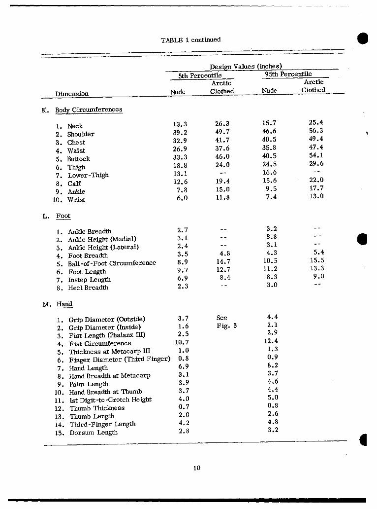
TABLE 1 continued
Design Values (inches)
5th Percentile 95th PercentileArctic Arctic
Dimension Nude Clothed Nude Clothed
K. Body Circumferences
1. Neck 13.3 26.3 15.7 25.4
2. Shoulder 39.2 49.7 46.6 56.3
3. Chest 32.9 41.7 40.5 49.4
4. Waist 26.9 37.6 35.8 47.4
5. Buttock 33.3 46.0 40.5 54.1
6. Thigh 18.8 24.0 24.5 29.6
7. Lower-Thigh 13.1 -- 16.6 --
8. Calf 12.6 19.4 15.6 22.0
9. Ankle 7.8 15.0 9.5 17.7
10. Wrist 6.0 11.8 7.4 13.0
L. Foot
1. Ankle Breadth 2.7 -- 3.2 --
2. Ankle Height (Medial) 3.1 -- 3.8 -- 63. Ankle Height (Lateral) 2.4 -- 3.1 --
4. Foot Breadth 3.5 4.8 4.3 5.4
5. Ball-of-Foot Circumference 8.9 14.7 10.5 15.5
6. Foot Length 9.7 12.7 11.2 13.3
7. Instep Length 6.9 8.4 8.3 9.0
8. Heel Breadth 2.3 -- 3.0 --
M. Hand
I. Grip Diameter (Outside) 3.7 See 4.4
2. Grip Diameter (Inside) 1.6 Fig. 3 2.1
3. Fist Length (Phalanx Ill) 2.5 2.9
4. Fist Circumference 10.7 12.4
5. Thickness at Metacarp 11 1.0 1.3
6. Finger Diameter (Third Finger) 0.8 0.9
7. Hand Length 6.9 8.2
8. Hand Breadth at Metacarp 3.1 3.7
9. Palm Length 3.9 4.6
10. Hand Breadth at Thumb 3.7 4.4
11. 1st Digit-to-Crotch Height 4.0 5.0
12. Thumb Thickness 0.7 0.8
13. Thumb Length 2.0 2.6
14. Third-Finger Length 4.2 4.8
15. Dorsum Length 2.8 3.2
I10
2 7 12
3 13
4 ~4
4 10
kol6
Fig. 8. Continued
91
m N N%. n nm 4I0
o 4q
04 0-f 0N * e ý ý
0
(U \ ce 04 N C- C% -4-1 - -4 -4 -1 -
a) N 0 ' OC CO 0 -L)Crzf Cf) a* -ý" na )t)' ,C q
cnn
a)
a) 0)~ P 4% C 01.4414C ý IAC ýrý jý
ox q --4 - 0
If) ~ ~ cd pf
4-) *j Cd
0o 0~ a)D-
0n *-4- aJ
"4 -J E n J A ) C0a )
a) bo cd 1.40
Q~U~ ) (u PQ a)
Q 0)
ri 004) 00 3
12
* ~AE
CN
Fig. 2. M -1 HELMET
TABLE 3
Dimensions of the M-1 Helmet
Dimension Size (Inches)
A. Length, front rim to rear rim 11 (maximum)
B. Height, at maximum angle 6 7/8
C. Top of head to top of helmet 2 (maximum)
D. Eyebrow ridge to front rim 2 (maximum)
E. Width, rim to rim 9 1/4 (maximum)
13
ci010 C*4~ LOi *4C1'
~c) 00m00
o> to CDC NC 0 00O C
to \0L
0; (7
N LC CO CO4 i LýCl c
or 0000 00 0't *O m *Y . *
Q)(1 0 0 *1 a)
0 41
00
0i "00 c r-.0 o -0 00 .0
Z- wr U --.- 00'0
14-
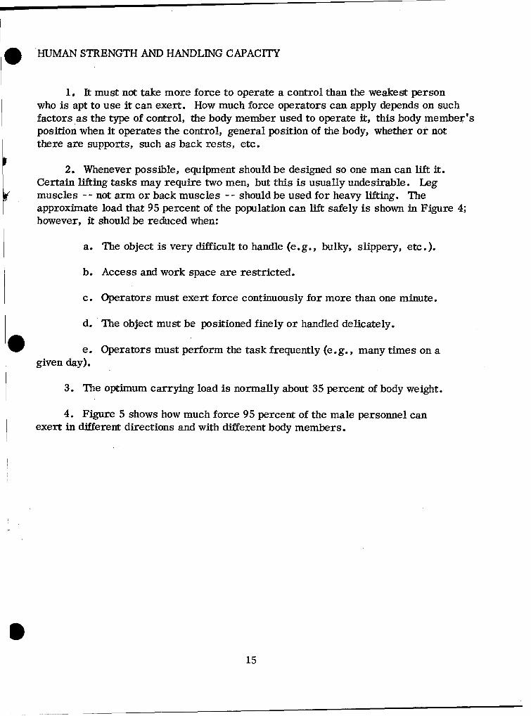
. HUMAN STRENGTH AND HANDLING CAPACITY
1. It must not take more force to operate a control than the weakest personwho is apt to use it can exert. How much force operators can apply depends on suchfactors as the type of control, the body member used to operate it, this body member'sposition when it operates the control, general position of the body, whether or notthere are supports, such as back rests, etc.
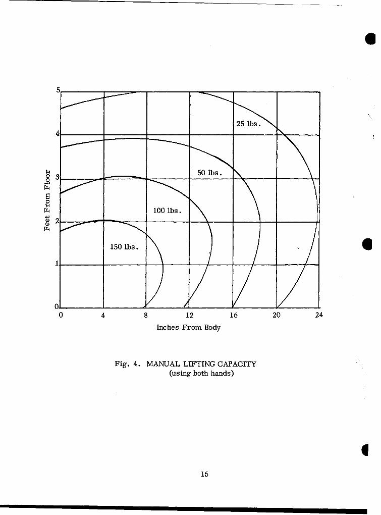
2. Whenever possible, equipment should be designed so one man can lift it.Certain lifting tasks may require two men, but this is usually undesirable. Legmuscles -- not arm or back muscles -- should be used for heavy lifting. Theapproximate load that 95 percent of the population can lift safely is shown in Figure 4;however, it should be reduced when:
a. The object is very difficult to handle (e.g., bulky, slippery, etc.).
b. Access and work space are restricted.
c. Operators must exert force continuously for more than one minute.
d. The object must be positioned finely or handled delicately.
e. Operators must perform the task frequently (e.g., many times on agiven day).
3. The optimum carrying load is normally about 35 percent of body weight.
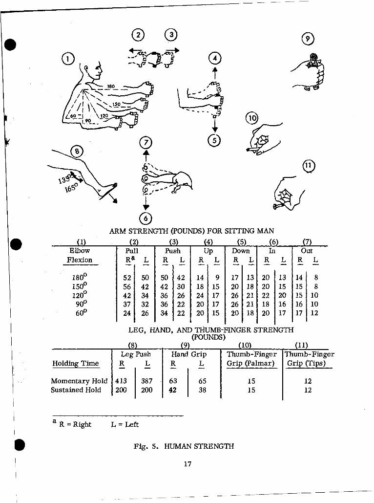
4. Figure 5 shows how much force 95 percent of the male personnel canexert in different directions and with different body members.
115
00
0
Il
4 100 Ibs.
150 Ibs.
0 4 8 12 16 20 24
Inches From Body
Fig. 4. MANUAL LIFTING CAPACITY(using both hands)
116
• ~(D @ ®
(Dl
/ IIL
0 0'80
ARM STRENGTH (POUNDS) FOR SITTING MAN
(2) (3) (4) (5) (6) (7)Elbow Pull Push Up Down In Out
Flexion RaL R L R L R L R L R L
1800 52 50 50 42 14 9 17 13 20 13 14 8
1SO 56 42 42 30 18 15 20 18 20 15 15 8
1200 42 34 36 26 24 17 26 21 22 20 15 10900 37 32 36 22 20 17 26 21 18 16 16 10600 24 26 34 22 20 15 20 18 20 17 17 12
LEG, HAND, AND THUMB-FINGER STRENGTH
(POUNDS)
(8) (9) (10) (11)Leg Push Hand Grip Thumb-Finger Thumb-Finger
Holding Time R L R L Grip (Palmar) Grip (Tips)
Momentary Hold 413 387 63 65 15 12Sustained Hold 200 200 42 38 15 12
a R = Right L = Left
Fig. 5. HUMAN STRENGTH
17
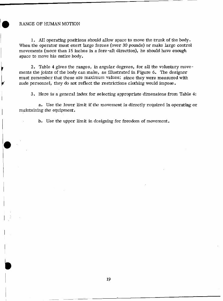
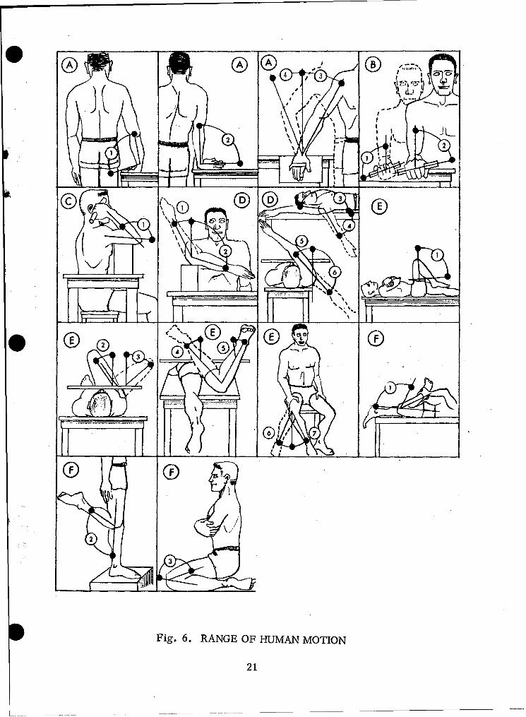
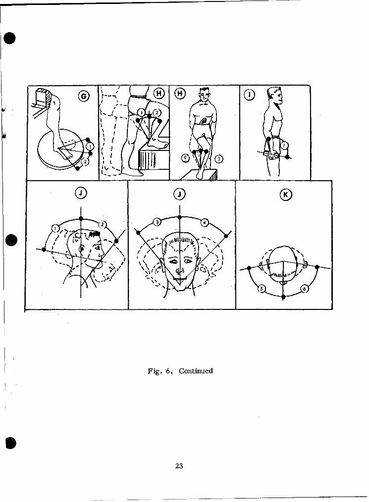
. RANGE OF HUMAN MOTION
1. All operating positions should allow space to move the trunk of the body.When the operator must exert large forces (over 30 pounds) or make large controlmovements (more than 15 inches in a fore -aft direction), he should have enoughspace to move his entire body.
2. Table 4 gives the ranges, in angular degrees, for all the voluntary move-ments the joints of the body can make, as illustrated in Figure 6. The designermust remember that these are maximum values; since they were measured withnude personnel, they do not reflect the restrictions clothing would impose.
3. Here is a general index for selecting appropriate dimensions from Table 4:
a. Use the lower limit if the movement is directly required in operating ormaintaining the equipment.
b. Use the upper limit in designing for freedom of movement.
19

TABLE 4
Range of Human Motiona
Lower UpperLimit Average Limit
Body Member Movement (degrees) (degrees) (degrees)
A. Wrist 1. Flexion 78 90 1022. Extension 86 99 1123. Adduction 18 36 274. Abduction 40 54 47
B. Forearm 1. Supination 91 113 135
2. Pronation 53 77 101
C. Elbow 1. Flexion 132 142 152
D. Shoulder 1. Lateral Rotation 21 34 472. Medial Rotation 75 97 1193. Extension 47 61 754. Flexion 176 188 1905. Adduction 39 48 576. Abduction 117 134 151
E. Hip 1. Flexion 100 113 1262. Adduction 19 31 433. Abduction 41 53 654. Medial Rotation (prone) 29 39 495. Lateral Rotation (prone) 24 34 446. Lateral Rotation (sitting) 21 30 397. Medial Rotation (sitting) 22 31 40
F. Knee Flexion 1. Prone 115 125 1352. Standing 100 113 1263. Kneeling 150 159 168
a These values are based on the nude body. The ranges are larger than they
would be for clothed personnel.
220
CA1~
I g-
1::
Fig. 6. RANGE OF HUMAN MOTION
21
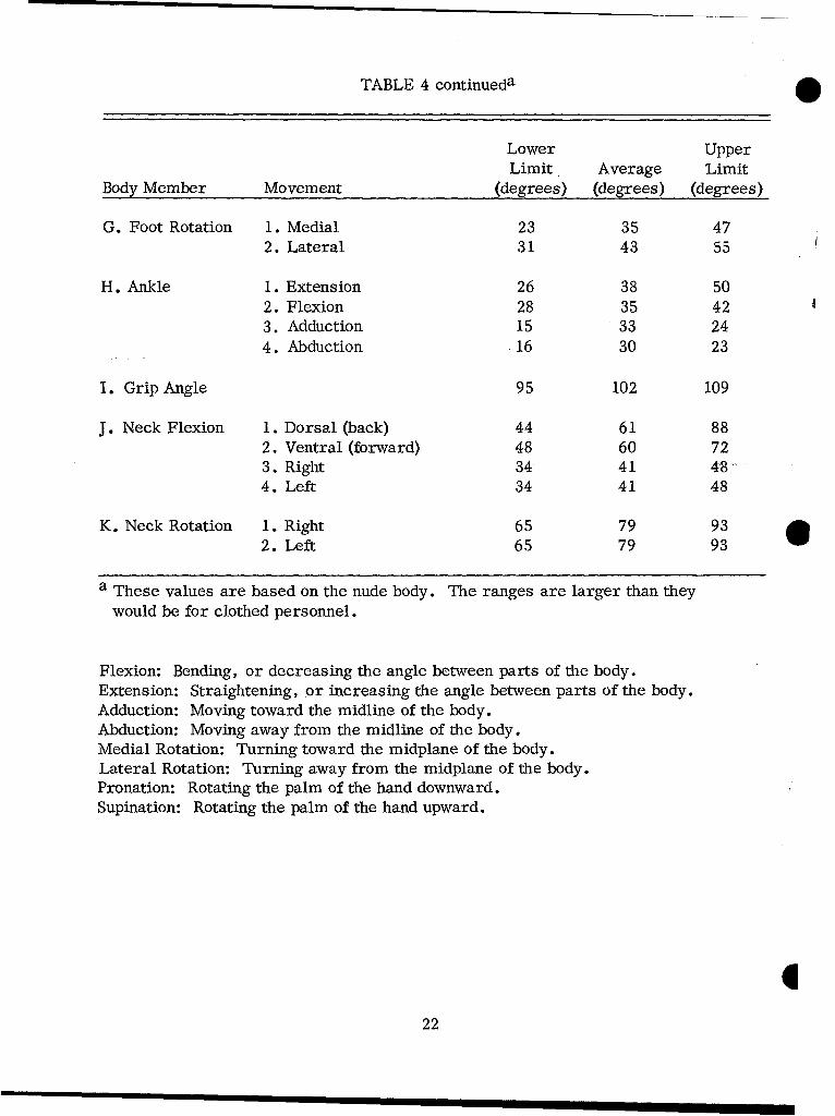
TABLE 4 continueda
Lower UpperLimit Average Limit
Body Member Movement (degrees) (degrees) (degrees)
G. Foot Rotation 1. Medial 23 35 472. Lateral 31 43 55
H. Ankle 1. Extension 26 38 502. Flexion 28 35 423. Adduction 15 33 244. Abduction 16 30 23
I. Grip Angle 95 102 109
J. Neck Flexion 1. Dorsal (back) 44 61 882. Ventral (forward) 48 60 723. Right 34 41 484. Left 34 41 48
K. Neck Rotation 1. Right 65 79 932. Left 65 79 93
a These values are based on the nude body. The ranges are larger than they
would be for clothed personnel.
Flexion: Bending, or decreasing the angle between parts of the body.Extension: Straightening, or increasing the angle between parts of the body.Adduction: Moving toward the midline of the body.Abduction: Moving away from the midline of the body.Medial Rotation: Turning toward the midplane of the body.Lateral Rotation: Turning away from the midplane of the body.Pronation: Rotating the palm of the hand downward.Supination: Rotating the palm of the hand upward.
222
011 2(2)
orI
5 6
' 1" , 1 I .
V,, \J71•
Fig. 6. Continued
23

ENVIRONMENT
GENERAL
1. There are three major categories of environmental factors which affectwheeled-vehicle design:
a. Environmental factors that design can control (e.g., illumination,ventilation rate, etc.).
b. Environmental factors that design cannot control (e.g., amount ofsolar radiation, dust, mud, rain, etc.).
c. Environmental factors that are a function of design (e.g, noxioussubstances, vibration, noise, etc.).
2. Throughout the design phase, designers should consider the environmentalextremes the system will be subjected to and how these extremes can affect humanperformance.
3. Designers should consult the most recent issue of AR 705-15, "Operation 6of Materiel under Extreme Conditions of Environment, " for criteria about designingfor extreme operating conditions.
THERMAL REQUIREMENTS
1. Temperature requirements for personnel compartments depend on the natureof tasks, the conditions they are performed under, and the clothing operators wear.
2. The requirements for hot and cold environments, as specified below, mustbe met under all operating conditions.
224
O Cold Environment
1. The reference temperature is measured 24 inches above the seat reference
point of the operator's normal position. In cold environments (AR 705-15), cab
compartments should be heated so the reference temperature does not fall below
+ 50 F dry bulb. In normal operating positions, air temperatures around theoperator's body should be within the range from 150 F dry bulb above referencetemperature to 100 F dry bulb below the reference temperature, e.g., if the refer -ence temperature is + 200 F, then temperatures at various parts of the body shouldbe between + 350 F and + 100 F. The heater should achieve these requirementswithin one hour after it is turned on.
2. There should be provisions for regulating the amount of heat the heaterdelivers, with devices like shutters, louvers, fan-speed controls, etc.
3. Vehicles used as ambulances should maintain a temperature of at least500 F dry bulb throughout the patient compartment.
4. In vehicles used as troop carriers, the troop-carrying area should beheated as provided in paragraph 1 above.
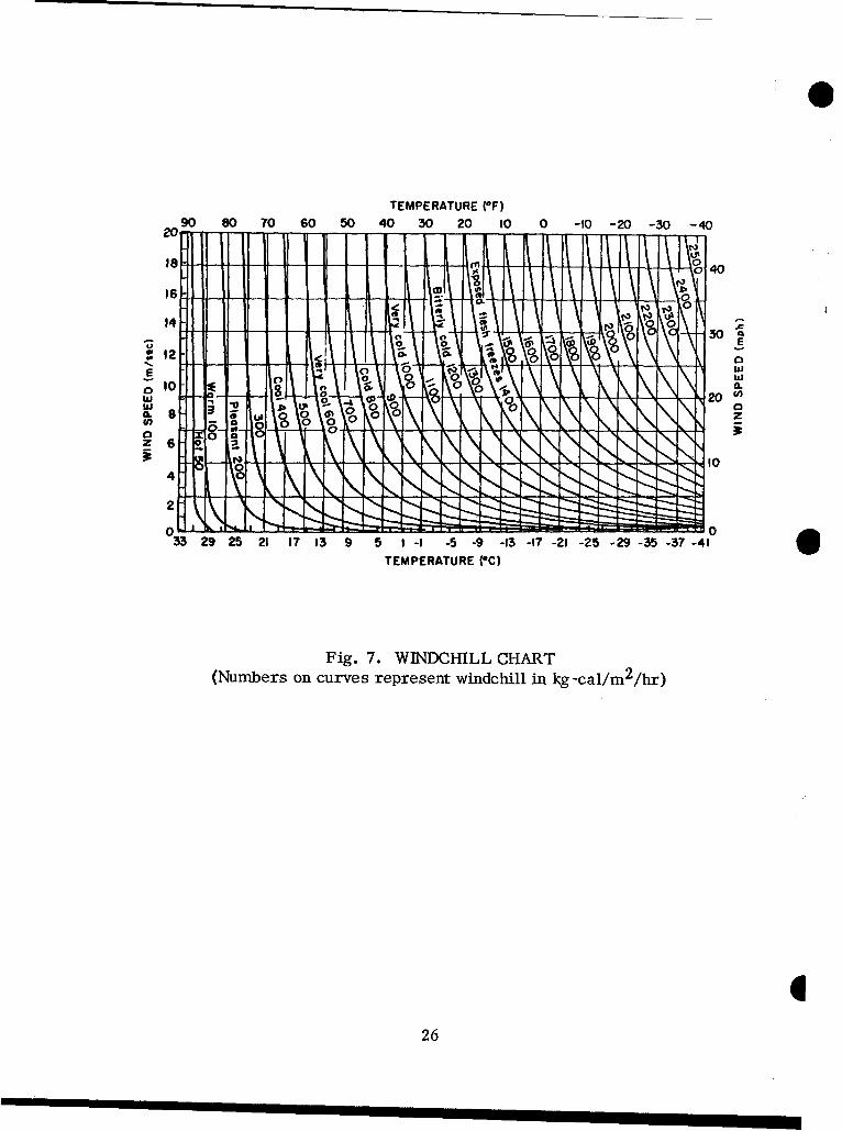
5. Open cabs and machine-gun kits call for special consideration of how* moving air can exaggerate the severity of cold environments. An empirical expres-
sion called the Windchill Index (WI) evaluates the way air movement and air tempera -ture, together, affect the environment's total cooling power.
a. Figure 7 gives values of WI as a function of wind speeds and airtemperatures.
b. In evaluating a windchill hazard, designers must consider air move-ment at personnel positions.
c. If personnel are exposed to a WI of 1200 or above while operating avehicle, they must be protected. As Figure 7 shows, windchill indices this largeare common even in temperate climates.
6. Surfaces that personnel touch -- i.e., gearshift levers, steering wheels,dash controls, seats, side panels, compartment walls, etc. -- should have surfaceswith low heat conductivity.
25
TEMPERATURE (OF)
2090 80 70 60 50 40 30 20 10 0 -10 -20 -30 -40
200-
14- A01 - - - -
we12 I 0 0 SR 10
Iem
10 SI-A 0 1O
4LJ22S
z 26
. Hot Environment
1. Several environmental factors determine how much heat stress personnelcan tolerate: dry-bulb air temperature, humidity, air movement, radiation, anddirect conduction from objects.
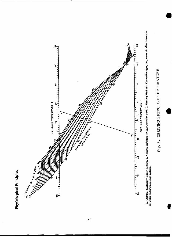
2. The effective temperature (ET) of an environment is an empirical thermalindex that considers how combinations of dry-bulb air temperature, humidity, airmovement, and clothing affect people. Numerically, it is equal to the temperatureof still, saturated air which would induce the same sensation.
3. Effective temperature may be read from Figure 8. This chart is based onmen wearing customary indoor clothing and doing sedentary or light muscular work.It does not include any additional heat stresses from special-purpose clothing, suchas gas masks, chemical protective clothing, or body armor. Likewise, it does notconsider radiant heat inputs, such as radiation from the sun or vehicle components.
4. The greater the input of radiant heat, the less reliably effective temperaturemeasures heat stress. However, if there is a radiant heat problem, environmentalheat stress can be assessed with the Wet-Bulb-Globe Thermometer Index (WBGT).This measure corrects the effective temperature for radiant-heat input; the apparatusand methods for measuring WBGT are described in Appendix 1 of TB Med 175.
5. The maximum ET (WBGT) at which humans perform reliably is 850 F.Designers should make every effort to avoid conditions which expose the individualto ET (WBGT) above 850 F for prolonged periods of time (one hour or more). Someeffective methods foi reducing the environmental heat stress are ventilation, insula-tion, and shielding.
6. If personnel can touch metal surfaces that may get as hot as 1150 F, specialprecautions are indicated: shielding, insulating, relocating components, or at leastadding warning decals, signs, or labels.
27
00
7a
E
00
a
S~.o
o* -b
0 00 t
28C
0ý' 0
_0~
Ci S
00
04
CLC
28C
. VENTILATION
1. Ventilation both cools personnel and controls air contamination. These twofunctions involve different problems, different measurements, and different solutions.
2. Cooling personnel with moving air should satisfy the requirements of the hot-environment section; however, the air should have even flow and distribution, so thatit does not blow on one part of the body.
3. Personnel compartments require at least 10 cubic feet of fresh air perminute per occupant, to control air contamination by body products. If there arealso other noxious substances in the compartment, this rate may not be sufficient.
4. Ventilation should provide air flow sufficient to dilute contaminants anddivert them from personnel positions.
Noxious Substances
1. Noxious substances can enter personnel compartments from the outsideenvironment, engine exhausts, heater exhausts, weapons, etc.
2. From the practical standpoint of controlling health hazards, the mostimportant contaminants in wheeled vehicles are carbon monoxide, ammonia, alde -hydes, and nitrogen oxides. In sufficient concentrations, these substances are lethal.In lower concentrations, they may incapacitate personnel through eye irritation,nausea, reduced mental alertness, and unconsciousness.
3. Carbon monoxide is particularly dangerous. Odorless, colorless, andtasteless, it cannot ordinarily be detected by the human senses. Its effects arecumulative, so concentrations which personnel can tolerate safely for short timesmay become dangerous in longer exposures.
4. The concentration of combustion products in the cab or troop area shouldnot exceed the limits as published in the latest issue of "Threshold Limit Values,"by the American Conference of Government Industrial Hygienists.
5. The composition of exhaust fumes varies with operating conditions. Forexample, concentrations of noxious substances are highest when starting and idlingthe engine in cold weather. In addition, exhaust composition depends on the engine'sloading condition, the ambient temperature, and the type of fuel.
6. Temporary disabilities, such as eye irritation and nausea, commonly occurwhen personnel are exposed to exhaust streams from multi-fuel engines, as whentransporting troops or in convoys.
29
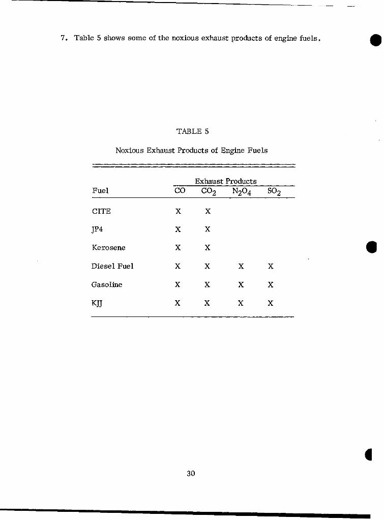
7. Table 5 shows some of the noxious exhaust products of engine fuels.
TABLE 5
Noxious Exhaust Products of Engine Fuels
Exhaust ProductsFuel CO CO 2 N2 0 4 SO 2
CITE X X
JP4 X X
Kerosene X X
Diesel Fuel X X X X
Gasoline X X X X
KJJ X X X X
30
NOISE
General
1. Advancing technology has given Army equipment greater power andincreased mobility, but with an accompanying increase in noise. When this noise,or sound-pressure level (SPL), becomes too great, a number of adverse effectsoccur: noise interferes with communications, it affects human performance, andit increases the probability of detection by an enemy.
2. The sensation of sound arises when certain frequencies of atmospheric -
pressure fluctuations impinge on the ear. The intensity of these fluctuations isexpressed in logarithmic units: decibels (dB). The decibel scale's referencepressure is defined as 0.0002 microbar, or 0.0002 dynes per square centimeter;at a frequency of 1000 Hertz (Hz), this reference is said to be the smallestpressure change that young men with good hearing can detect. A scale measuringpressure fluctuations in decibels referred to 0.0002 microbar is termed sound-pressure level (SPL).
3. Types of Noise. Noises may be classified into five general categories:
a. Steady-State Wide-Band Noise (continuous noise), e.g., tank noise,air moving through ducts, ambient noise.
b. Steady-State Narrow-Band or Pure-Tone Noise, e.g., circular saws,transformer noise, turbine whine.
c. Impulse (impact) Noise, e.g., drop forge, hammer, gunfire, doorslamming.
d. Repeated Impulse (impact) Noise, e.g., riveting, pneumatic hammers,machine guns.
e. Intermittent Noise, e.g., aircraft flyovers, automobile traffic, passingtrain.
31

Speech -Interference Level
1. Communications may be affected by ambient noise -- both surrounding noiseand noise in the communication system itself.
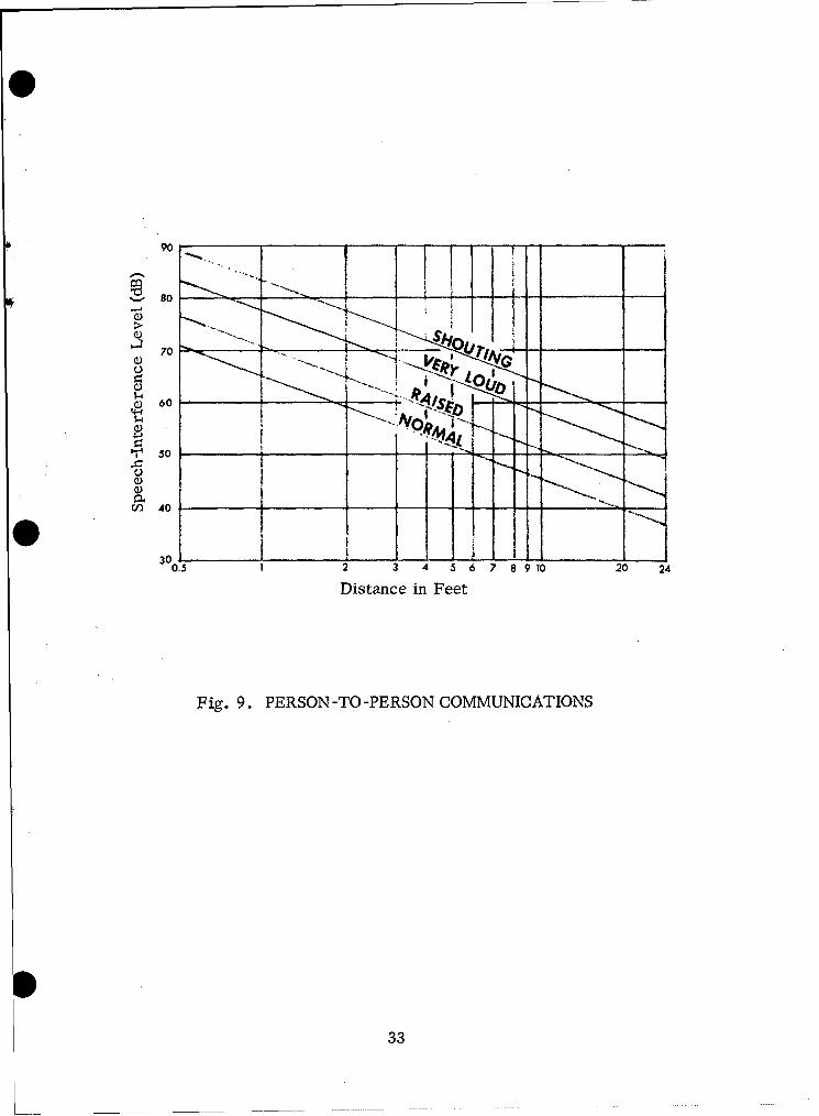
2. The speech-interference level (SIL) describes how effectively noise masksspeech. SIL is defined as the average (in dB) of the masking noise's sound levelsin three octave bands: 600 to 1200, 1200 to 2400, and 2400 to 4800 Hertz (Hz).Sometimes speech interference can be predicted better by also averaging in the300 -600 Hz band if it is 10 dB or more louder than the 600-1200 Hz band. The SILcannot be used if the masking noise has intense low-frequency components or if itis concentrated in a narrow band. The distance and voice level which will permitreliable conversation (70 percent monosyllabic word intelligibility) for direct person-to-person (non-electrically aided) communications at various SIL without lip readingis shown in Figure 9.
3. Voice communication is the most common method of requesting and giving
information. In military systems, voice messages are transmitted in two ways:
a. Electrically, by radio or telephone.
b. Person-to -person.
4. Electrically transmitted speech depends greatly on the characteristics of 6the microphone, transmission equipment, and the earphones. However, direct andelectrically transmitted voice communications have certain limitations in common;one of these limitations is the acoustical environment of both speaker and listener,which has a very important influence on the effectiveness of communication.
5. The frequency range from about 200 to 6000 Hz contains most of the energyrequired for perfect speech intelligibility. However, this range may be narrowedto 300 to 4500 Hz with little loss in intelligibility.
6. Most of the information in English speech is conveyed by the consonants.Unfortunately, consonants are high-frequency sounds with relatively little energy,so they are more subject to masking than vowels. Conversely vowels have moreenergy but transmit a limited amount of intelligence. For example, the s sound isa high-frequency sound, whereas the vowel o is a low-frequency sound.
7. To measure how a noisy environment affects intelligibility, trained talkersand listeners should speak phonetically balanced word lists in accordance with theprovisions and word lists established by the American Standards Association. *
* American Standard S 3.2-1960, American standard method for measurement
of monosyllabic word intelligibility. American Standards Association, Inc., E10 E. 40th St., New York 16, New York.
32
90 ~ 1 -_____
so - ---
Q)
70 1______
60.
0. 05 - + 2 I4 5 6 89102-2
Distance in Fee
Fig 90 PESN-O-ESNCMUIAIN
o3
Equipment Design Criteria
1. When there are steady-state noise sources in the environment -- i.e., on-vehicle generators, air conditioners, etc. - - the maximum noise level for ArmyMateriel Command equipment should not exceed the levels set forth in the latestissue of HEL Standard S-1-63.
2. When the system requires continuous person-to -person communication (notelectrically aided), the steady-state noise level should not exceed that shown in thelatest issue of HEL Standard S-I-63.
I34
O VIBRATION
1. Vibration can affect performance adversely when:
a. At high levels, it causes critical body damage.
b. It makes dials, lettering, and sight reticles difficult to read.
c. It makes controls, tools, or other objects difficult to manipulate.
d. It contributes to increased fatigue, nervousness, and irritabilitythat can lead to oversights, errors in judgment, etc.
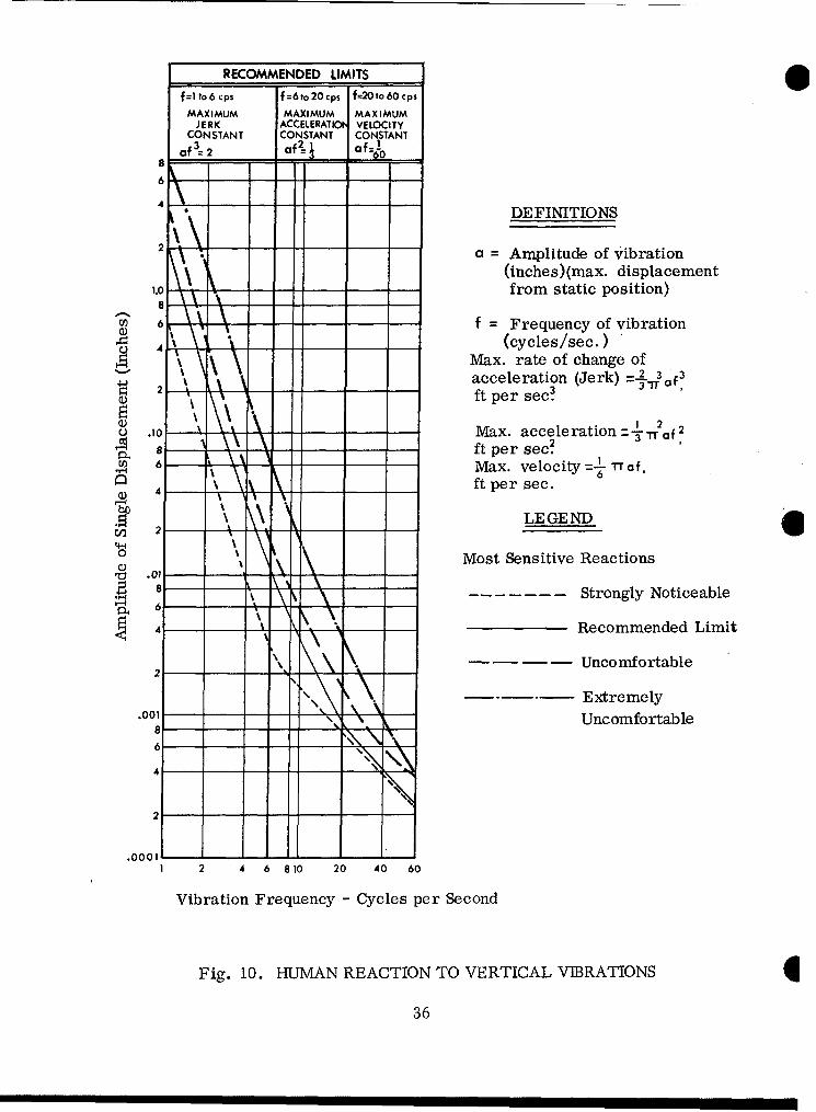
2. In designing equipment, vibration should be:
a. Minimized wherever practical.
b. Kept below the "strongly noticeable" and "recommended limit" rangeof Figure 10 wherever possible.
c. Always kept below the "uncomfortable" to "extremely uncomfortable"*• range of Figure 10.
3. Vibration can be reduced and controlled by:
a. Isolating equipment from vibration sources by shock mountings, fluidcouplings, etc.
b. Properly balancing rotating elements of equipment.
c. Providing damping materials or cushioned seats for standing orseated personnel.
35
RECOMMENDED LIMITS
f=lto6 cps f=6to 20 cps f=2Oto 60 cps
MAXIMUM MAXIMUM MAXIMUMJERK ACCELERATIC* VELOCITY
CONSTANT CONSTANT CONSTANTf3 Of2-i af
Of 12 0 60
6
4 _ DEFINITIONS
2 a = Amplitude of vibration
(inches)(max. displacement1.0 -- from static position)
w 6 \\\" - f = Frequency of vibration- -\ .(cycles/sec.)
Max. rate of change of2 \ -- ___acceleration (Jerk) =-2 3
4ý 2 ~~~ft per sec? f f
o .10 -i N-- -tMax. acceleration= 1-.1TTf 2A 8 ft per see?
S6 Max. velocity='- Trf,4 \ft per sec.
~ LEGEND
0 Most Sensitive Reactions
e.01 - iS-------Strongly Noticeable
2- - Recommended Limit
- - ..- . Uncomfortable
\ -*-*- Extremely\\
.001- -- Uncomfortable
.0001 7 - I I -1 2 4 6 810 20 40 60
Vibration Frequency - Cycles per Second
Fig. 10. HUMAN REACTION TO VERTICAL VIBRATIONS
36
RADIATION
1. Radiation problems are becoming increasingly important as new uses forradioactive materials and new methods for handling them are developed. Radiationis extremely dangerous, and its health hazards are well known.
2. Protective devices, permissible dosages, and dosage rates change as newdata accumulate; therefore, designers should contact the U. S. Army SurgeonGeneral for the latest available data.
3. Microwave radiation: The maximum microwave energy that personnel maybe exposed to is given in AR 40-583.
4. Nuclear radiation: To find the maximum nuclear radiation that personnelmay be exposed to, designers should consult the Atomic Energy Commission andthe U. S. Army Surgeon General.
37
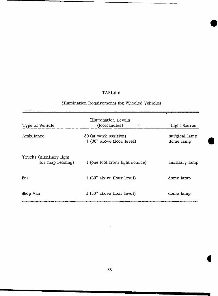
TABLE 6
Illumination Requirements for Wheeled Vehicles
Illumination LevelsType of Vehicle (footcandles) Light Source
Ambulance 30 (at work position) surgical lamp1 (30" above floor level) dome lamp
Trucks (Auxiliary lightfor map reading) I (one foot from light source) auxiliary lamp
Bus 1 (30" above floor level) dome lamp
Shop Van 1 (30" above floor level) dome lamp
338
. VISIBILITY
General
1. A vehicle driver should have a 180-degree field of forward vision (90-degreefield of forward vision on each side of the vehicle's longitudinal centerline). A 220-degree field of forward vision is even more desirable.
2. In his normal driving position, the driver should be able to see the groundat a point 20 feet in front of the vehicle -- or, if at all possible, within ten feet infront of the vehicle. It is also very desirable to allow for looking upward at least15 degrees above the horizontal.
3. Door posts, windshield-wiper motors, and other devices should notobstruct vision.
4. Transparent materials used for windshields or windows should neitherdistort nor obscure vision.
5. Interior surfaces shi0uld not reflect light or glare to the operator.
6. Side closures should operate easily so the driver and assistant driver canlook to the rear on both sides of the vehicle.
7. When possible, there should be a rear window so the driver can see back-ward over the cargo bed.
Illumination
1. To perform their various tasks efficiently, vehicle personnel must havecertain minimum amounts of light (Tables 6, 7, and 8).
2. Auxiliary lighting should be provided where it is needed for tasks likemap reading, troubleshooting, etc.
3. Illumination of visual work areas is considered satisfactorily uniform if theminimum illumination of any point within the area is at least two-thirds as bright asthe maximum illumination.
39

TABLE 7
Illumination Requirements for Representative Tasks
Illumination Levels (footcandles) LightTask Recommended Minimum Source
Perceiving small details with low 150 100 Generalcontrast for prolonged times, or Serviceswhere speed and accuracy are plusessential (examples: repairing supple -small components, inspecting dark mentarymaterials, layout drafting).
Perceiving small details with fair 100 50 Generalcontrast where speed and accuracy Servicesare not so essential (examples: and/orhandwriting, electronic assembly). supple-
mentary
Prolonged reading, desk or bench 70 50 Generalwork, general office and laboratory Serviceswork (examples: assembly work, and/orfiling records). supple -
mentary
Occasional reading, recreation, 50 30 Generalreading signs where visual tasks Servicesare not prolonged (example: reading or supple-a bulletin board). mentary
Perceiving large objects with good 20 10 Generalcontrast (example: locating objects Servicesin bulk supply warehouse).
Passing through walkways, handling 20 10 Generallarge objects (example: loading from Servicesa platform).
40
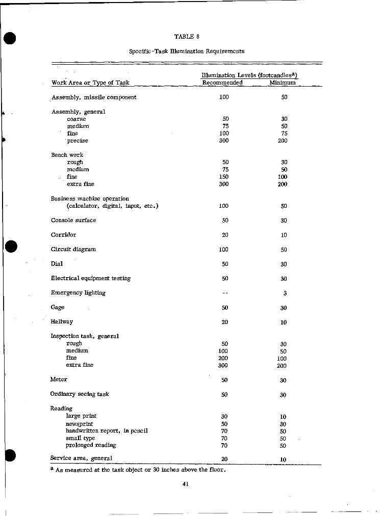
TABLE 8
Specific -Task Ilumination Requirements
Illumination Levels (footcandlesa)Work Area or Type of Task Recommended Minimum
Assembly, missile component 100 50
Assembly, generalcoarse 50 30medium 75 50fine 100 75precise 300 200
Bench workrough 50 30medium 75 50fine 150 100extra fine 300 200
Business machine operation(calculator, digital, input, etc.) 100 50
Console surface 50 30
Corridor 20 10
Circuit diagram 100 50
Dial 50 30
Electrical equipment testing 50 30
Emergency lighting 3
Gage 50 30
Hallway 20 10
Inspection task, generalrough 50 30medium 100 50fine 200 100extra fine 300 200
Meter 50 30
Ordinary seeing task 50 30
Readinglarge print 30 10newsjprint 50 30handwritten report, in pencil 70 50small type 70 50prolonged reading 70 50
Service area, general 20 10
a As measured at the task object or 30 inches above the floor.
41
Dark Adaptation
i. Dark adaptation is the process by which the eyes become more sensitive indim light. The eyes adapt almost completely in about 30 minutes, but the length ofdark adaptation depends on the color and intensity of the previous light.
2. Low-brightness red light is used to do visual work while maintaining maxi-mum dark adaptation. This red light is obtained by passing white light through afilter that transmits only wavelengths longer than 620 millimicrons (red). A filterwith a higher cut-off would maintain dark adaptation still more effectively, but itwould waste too much of the available light energy.
3. Where dark adaptation is required, instrument or display markings shouldbe illuminated with red light (620 millimicrons and above). The brightness of themarkings should be between 0.02 foot-Lambert and 0.1 foot-Lambert.
4. White light is incompatible with dark adaptation. If it is dimmed enoughthat it does not interfere with dark adaptation, it will not be bright enough to workby.Where both white light and dark adaptation are to be required, the conflict shouldbe resolved by evaluating the priorities of the operator's tasks (e.g., if night visionis more important than reading maps, use dim red lighting). Colors often appeardifferent under different types of illumination; unless a display will always be usedunder white light, do not use color coding.
5. At low levels of illumination, red light degrades the eye's dark adaptationless than any other color.
6. Instrument panels should be designed and located for both day and night use.
442

* Brightness Ratios
The brightness ratios between lightest and darkest areas and/or between taskand surroundings should be no greater than specified in Table 9.
TABLE 9
Brightness Ratios
Environmental ClassificationaComparison A B C
Between tasks andadjacent darker surroundings 3 to 1 3 to 1 5 to 1
Between tasks andadjacent lighter surroundings 1 to 3 1 to 3 1 to 5
Between tasks andmore remote darker surfaces 10 to 1 20 to 1 b
Between tasks andmore remote lighter surfaces 1 to 10 1 to 20 b
Between luminaires andadjacent surfaces 20 to 1 b b
Between the immediate work areaand the rest of the environment 40 to I b b
a A -- Interior areas where reflectances of entire space can be controlled
for optimum visual conditions.B -- Areas where reflectances of immediate work area can be controlled,
but there is only limited control over remote surround.C -- Areas (indoor and outdoor) where it is completely impractical to
control reflectances and difficult to alter environmental conditions.
b Brightness -ratio control not practical.
43
Glare
1. One of the most serious of all illumination problems is glare or dazzle --
relatively bright light shining into the observer's eyes as he tries to observe arelatively dim visual field. Glare not only reduces visibility for objects in the fieldof view, but causes visual discomfort.
2. Direct glare arises from a light source within the visual work field. Itshould be controlled by:
a. Avoiding bright light sources within 60 degrees of the center of the visualfield. Since most visual work is at or below the eye's horizontal position, placingluminaires high above the work area minimizes direct glare.
b. Using indirect lighting.
c. Using more relatively dim light sources, rather than a few very bright ones.
d. Using polarized light, shields, hoods, or visors to block the glare inconfined areas.
3. Reflected glare refers to reflections from bright surfaces in the visual field.It should be controlled by:
a. Using surfaces that diffuse incident light, rather than reflecting itspecularly.
b. Arranging direct-light sources so their angle of incidence to the visualwork area is not the same as the operator's viewing angle.
4. These glare-control methods assume the operator is using unaided vision.Eyeglasses reflect glare into the eyes if a bright light behind the viewer is between30 degrees above and 45 degrees below the line of sight -- or if it is within 20 degreesleft or right of the line of sight.
5. Reflected glare from work surfaces is a common, but frequently overlooked,cause of reduced performance in visual tasks.
Reflectances
Large surface areas should be non-glossy. Some non-critical small areas,
such as door frames and molding, may be glossy if ease of cleaning is essential.
444
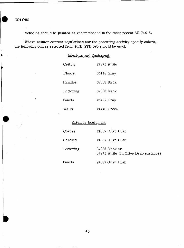
. COLORS
Vehicles should be painted as recommended in the most recent AR 746-5.
Where neither current regulations nor the procuring activity specify colors,the following colors selected from FED STD 595 should be used:
Interiors and Equipment
Ceiling 27875 White
Floors 36118 Gray
Handles 37038 Black
Lettering 37038 Black
Panels 26492 Gray
Walls 24410 Green
[0 Exterior Equipment
Covers 24087 Olive Drab
Handles 24087 Olive Drab
Lettering 37038 Black or37875 White (on Olive Drab surfaces)
Panels 24087 Olive Drab
45
AUTOMOTIVE SUB -SYSTEMS
BATTERIES
1. One man should be able to change a storage battery within ten minutes, usingon-equipment materiel (OEM).
2. Batteries and their compartments should be designed so they can be cleanedand serviced without removing any other components.
3. To prevent incorrect connections, the battery's positive and negative termi-nals should be labeled and have different sizes or shapes.
4. Battery-retaining devices should use either fasteners that can be removedwithout hand tools, or nuts and bolts the same size as the battery-terminal clamps.
5. Batteries should be mounted on racks where they are protected yet easilyaccessible (i.e., under the hood, but within the operator's reach when the hood isopen). Where such a location is not feasible, there should be corrosion-resistant,roll-out racks, slides, or hinges that can be pulled out conveniently without dis- -1connecting them.
6. Battery-access covers should be fastened with quick-release fasteners.It should be readily apparent that an access cover is either loose or fastened. Ifthe cover is hinged, there must be enough clearance to open the door.
7. The storage battery compartment itself, and any adjacent metal parts thatbattery leakage might corrode, should have an acid-resisting paint or coating. Thereshould also be openings for ventilation and drainage.
8. Wherever the starter cable passes through a metal part, it should be insulatedwith an acid-proof and waterproof bushing to prevent grounding.
9. Wherever both battery and fuel tank are under the driver's seat, they shouldbe partitioned from each other, and both compartments should have separate covers,ventilation, and drainage to the outside.
10. There should be a slave receptacle for auxiliary starting. It should belocated near the front of the vehicle and away from areas where there may be fuelvapor.
11. Battery compartments should allow enough space for heating pads and
insulation used to winterize the vehicle. I
46
. BRAKES
1. There should be two separate ways to apply the brakes on every vehicle.One such means should be an auxiliary parking brake. If the two separate brakesystems are connected in any way, they should be constructed so a failure in onesystem will not degrade the other. (Ref. I.C.C. Regulation, parts 190-197,August 1963.)
2. Every truck used to tow a vehicle with full air brakes should have a meansof activating the towed vehicle's brakes.
3. In buses, the front wheels and rear wheels should have separate brakesystems, so that even if the connection to one set of wheels breaks, the driver canstill apply the brakes to the other wheels.
4. Brake tubing and hose should be mounted so fittings are accessible withordinary hand tools.
5. All connections for air, vacuum, or hydraulic braking systems should beaccessible to the operator.
or 6. All vehicles using air or vacuum brakes should have a reserve capacity
or a reservoir that insures full braking even with the engine off.
7. Every air or vacuum reservoir should have a check valve so that leakagein the air or vacuum supply line will not deplete the reservoir. Means should beprovided to determine that the check valve is in working order.
8. All vehicles with compressed-air brakes should have warning signals thatoperate continuously as long as pressure is below a fixed threshold pressure (notless than one-half the cut-out pressure of the compressor governor). These warn-ings should be designed so they are readily audible or visible to the driver. Inaddition, each vehicle should have a pressure gauge indicating the braking pressurein pounds per square inch.
9. All vehicles with vacuum brakes should have a readily audible or visiblewarning signal which gives continuous warning as long as the vacuum in the supplyreservoir is less than eight inches of mercury. In addition, each vehicle shouldhave a vacuum gauge indicating the braking vacuum in inches of mercury or poundsper square inch.
47

10. The master cylinder should be located where it is easily accessible
for servicing.
11. Air reservoir drains should be readily accessible.
48
. CANVAS AND ACCESSORIES
1. When cargo vehicles are used for troop transport or workspace, there shouldbe between 60 to 75 inches of clearance between the tarpaulins and bows covering thebed and the cargo floor.
2. One man should be able to gain access to the cargo compartment within threeminutes, from front or rear, with the tarpaulin and curtains in place.
3. Tarpaulin bows and ropes should be easy to unfasten, and bows should bedesigned so personnel wearing gloves can remove them from sockets under wet,muddy, or freezing conditions.
4. Tarpaulin bows (especially wooden ones) should be designed so moisture,rust, or dirt will not make them seize in their sockets.
5. Tarpaulins and cab tops should be shaped and supported so they shed debrisand do not form water or ice pockets, whether the vehicle is operating or parked.
6. Cab tops, tarpaulins, and curtains should be protected from chafing andflapping.
7. Tarpaulin and cab -top bow sockets should have adequate drain apertures.
8. The cab should be designed so one man can convert it from open to closedtype, and vice versa, in ten minutes or less.
9. Tarpaulins, end curtains, and bows should be designed so two men canremove or install them in ten minutes or less.
NOTE: The time restrictions in 8 and 9 above do not apply to heavy paddedarctic cabs and enclosures.
10. Tarpaulins and end curtains should be fire resistant.
11. Pins and other retaining devices should have the largest working clearancesthat still assure they will be retained properly.
12. Pins and other retaining devices should be designed so men wearing glovescan remove and replace them.
13. There should be chains to keep retaining pins and devices from getting lost.
14. There should be provision for rolling up the sides of cargo-area tarpaulinsto ventilate the troop area.
49

15. There should be space to stow stakes and bows on the vehicle.
16. Vehicles that transport troops should have safety straps at the
rear of the vehicle.
5
50
O INTRA-VEHICULAR COUPLING DEVICES
1. Coupling devices should be long enough that they do not restrict a vehicle'smaneuverability when it tows another vehicle.
2. Coupling devices should be designed so normal use will not damage them.
3. Coupling devices should be designed so they cannot be mismated.
4. Vehicles with air-over-hydraulic brakes or air brakes should have pro-visions at front and rear for connecting to another vehicle's brake system and con-trolling its brakes while towing it.
5. There should be suitable precautions to protect intra -vehicular couplingsfrom accidental disconnection, kinking, entanglement, dragging, abrasion, orpinching during operation.
6. Every full trailer should be coupled to the towing vehicle's frame with asafety chain or chains.
7. Chains or cables should be connected so the tow-bar will not drop to theground if it fails.
8. Each chain or cable should have an ultimate strength at least equal to thegross weight of a loaded trailer being towed.
51
DRAINS AND VENTS
1. Drain valves should be accessible, dependable, and have simple operatingmechanisms.
2. Vents and drains should be designed so mud, ice, or other foreign matterwill not clog them.
3. Drain plugs and valves should be designed to resist seizing, whether theyare open or closed.
4. All drain plugs should be the same size, if possible; if not, the number ofdifferent sizes should be minimized.
5. Drains should be designed so they empty lubricants and hydraulic fluidscompletely.
6. Fluids should drain to the outside of the vehicle, without falling on obstruc -
tions or splashing onto vehicle components. Draining of fluids should not requireany special equipment.
7. Drains that purge pneumatic-system reservoirs should be readily accessible,and they should drain tanks completely.
8. Drains and vents should be located where crew members can clean andcheck them easily.
9. Drains and vents should be easy to identify. They should be located wherethey are easy to close and check before floating or swimming operations.
10. Floating or swimming vehicles should have an instruction plate giving
locations for drains and vents, and procedures for operating them.
11. Vehicles that swim should have bilge pumps.
12. Regardless of whether they are open or closed, drains in the cargo bodyshould remain flush to the surface in which they are located so they do not interferewith the loading, stowage, or unloading of cargo.
552
O EXHAUST SYSTEMS
1. Exhaust systems should be built so they are leakproof. They should bemounted to the chassis securely, yet loosely enough that flexion between componentswill not damage them.
2. The exhaust pipe should be attached to the exhaust manifold securely, yetso it can be disconnected quickly. It should not interfere with removing the engine.
3. The exhaust system should be located or protected so personnel will notcontact hot surfaces.
4. The exhaust system and vehicle should be designed to keep exhaust fumesfrom entering the cab and troop compartments.
5. The exhaust system should reduce exhaust noise. It should not heat tiresunduly, disturb road dust, or clog in mud or in swimming operations.
6. A bus' exhaust system should discharge to the atmosphere at least sixinches in front of the bus' rearmost part so that exhaust gases are not drawn up andinto open rear doors or windows.
7. Exhaust systems should be designed to eliminate any safety hazard, suchas starting grass fires when operating in areas of high grass.
53
ENGINES
1. Air cleaners should be located where they are easy to remove, service, andinstall. It should be possible to service them with OEM tools and equipment.
2. Engine-timing marks should be easily visible.
3. Engine -timing marks should have a visible reference point on the engine,so timing can be checked when the engine is installed in the vehicle.
4. Where required, an air -restriction gauge should be located where it isvisible to the operator.
5. Vehicles should have engine over-speed governors.
6. Over-speed governors should be made tamper-proof.
7. Fan belts and other drives that require adjustment should be simple andreadily accessible.
8. Removing oil-drain plugs should allow the pan to drain completely if thevehicle is on a level surface, so the operator does not have to move the vehicle.
9. Fuel and coolant pumps, starter motors, generators, filters, and otherengine accessories should be accessible without removing the engine from the vehicle.It should be possible to replace any engine accessory without removing more than oneother engine accessory.
10. It should be possible to remove the engine from the chassiswithout firstremoving engine accessories such as starters, generators, pumps, manifolds, etc.
11. Fuel and oil filters should be located where they can be cleaned and replacedwithout disassembling other parts of the vehicle.
12. Spark plugs should be located in an accessible place. It should be possibleto remove them with OEM tools.
13. Ignition-system wiring should be mounted and routed so vehicle vibrationor personnel cannot break connections accidentally.
14. Engines that use diesel or multi-fuels should be designed so it is -easy todrain the primary fuel filter daily.
15. Engines used as electric or pneumatic power sources, and vehicular engineson radio-carrying vehicles, should have tachometers and hand throttles which can belocked at part-throttle positions.
54
. FUEL SYSTEM
1. Neither the fuel tank nor its supports or intake pipe should project beyondthe vehicle's overall width. Ideally, these components should be located slightlyinward of its overall width.
2. As a precaution in case of collision, the fuel tank should not be forward ofthe front axle of the power unit it is on.
3. The fuel tank and its intake pipe must not be inside or over parts of thevehicle that carry passengers.
4. The fuel container should be designed so that, if the vehicle turns over,fuel'will not spill faster than one ounce per minute.
5. The fuel system should be constructed so gravity or syphoning cannot feed
fuel directly to the carburetor or injector.
6. Some specific features of tanks for liquid fuels are:
a. Excess-flow valve: When fuel is forced from the tank with pressure* devices, there should be a safeguard to stop the flow of fuel if the fuel feed line breaks.
b. Fueling rate: Tactical and combat vehicles' fuel tanks that hold 50 gallonsor more should be able to accept fuel at 50 gallons per minute. Tanks that hold lessthan 50 gallons should accept fuel fast enough to be filled in one minute.
c. Air vent: Every fuel tank should have a non-spill air vent. It may bemounted separately or combined with the filler cap or safety vent.
7. The fuel tank's liquid capacity should be marked on it.
8. The fuel-tank drain plug should be accessible and located so it can drain thefuel tank completely. Personnel should be able to remove it with OEM.
9. The nozzle opening in the fill-pipe should be outside the cab or body. Itslocation must minimize the likelihood of spilling fuel on the exhaust system or battery.
10. The fuel fill-pipe should never be more than four feet above the ground orabove the base of the work platform used for refueling.
555
HORN
1. Where horns are required, they should produce complex sound in the audiofrequency band between approximately 250 and 2,000 Hz. Its sound-pressure levelbetween these frequency limits, measured three feet from the exit of the horn and onits axis, should be 110 decibels.
2. Sound-level measurement should be made with instruments that comply withthe latest revision of American Standard Z 24.3-1944.
3. Sound level should be measured with the horn installed in the vehicle. Thereshould not be any reflecting walls or obstacles (other than the ground) within 100 feetof the horn when its sound level is measured.
HEATERS
1. Refer to the environmental section (page 24) for heating and ventilationrequirements.
2. Heaters should be located or protected so personnel cannot touch parts that 6are hot enough to cause burns.
3. Van heaters should be fastened securely so they will stay in place duringnormal use or in case the vehicle overturns.
4. Van heaters should be built so they will not come apart -- exposing partslike exhaust stacks, pipes, or conduits -- if the vehicle overturns.
5. Any heater that burns oil, gas, liquified petroleum gas, or any other com-bustible material, must discharge its combustion products outside the vehicle.
6. Cab heater controls should be accessible to the vehicle operator.
7. The heater's air inlet should be positioned so it cannot take in eitherengine or heater exhaust gases.
8. It should be possible to replace ignitors, resistors, and other "high-mortality" items without having to remove the heater from the vehicle.
556
. LADDERS -- TRAILERS AND VANS
1. Ladders should be used as follows:
a. Be pgovided wherever personnel have to change elevation abruptly bymore than 16 inches in operating or maintaining the vehicle.
b. Be designed, installed, or provided to give the most immediate andefficient access to and between work places.
c. Be built sturdily enough to support the combined weight of the mostmen (assuming 250 pounds per man) and equipment that will be on them at once.
d. Have nonskid surfaces wherever personnel will step, walk, or stand.
e. Have no obstruftions, edges, notches, or burrs which could injurepersonnel or damage hoses and cables.
f. Be adequately marked against any dangers their use involves (e.g.,unavoidable low overhead, possible shock, etc.).
* g. Wherever possible, be designed so one man -- but never more thantwo men -- can carry, handle, and position the ladder.
2. More specifically, ladder designs should consider:
a. Limited spaces and clearances.
b. Probable environmental conditions, particularly whether the structureis likely to get wet, icy, or snowy.
c. The type, direction, and frequency of traffic.
d. Loads or other encumberances personnel must carry.
e. The configuration and weight of other equipment that may have to bemoved over the ladder.
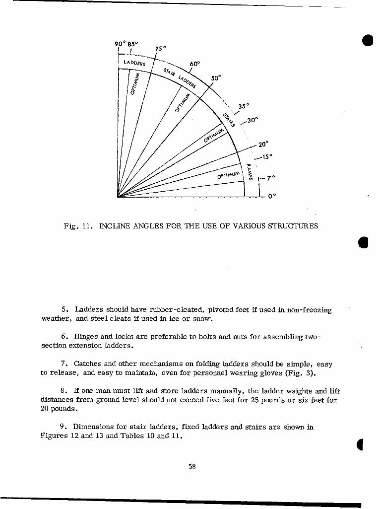
3. The primary basis for selecting a ladder is the slope it must have to getenough structural strength in the available space. Figure 11 shows the preferredand critical angles of incline for various structures.
4. When operational or maintenance vans will remain in one location for aS period of time, stair ladders should be used.
57
900 850 7
5200
, \.. 350
300
Fig. 11. INCLINE ANGLES FOR THE USE OF VARIOUS STRUCTURES
6
5. Ladders should have rubber-cleated, pivoted feet if used in non-freezingweather, and steel cleats if used in ice or snow.
6. Hinges and locks are preferable to bolts and nuts for assembling two-
section extension ladders.
7. Catches and other mechanisms on folding ladders should be simple, easyto release, and easy to maintain, even for personnel wearing gloves (Fig. :3).
8. If one man must lift and store ladders manually, the ladder weights and liftdistances from ground level should not exceed five feet for 25 pounds or six feet for20 pounds.
9. Dimensions for stair ladders, fixed ladders and stairs are shown inFigures 12 and 13 and Tables 10 and 11.E
58
I i i I I l I l I I I I ~IQI II I I I II I I II
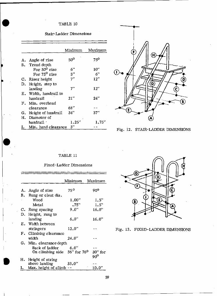
TABLE 10
Stair-Ladder Dimensions
Minimum Maximum
A. Angle of rise 500 750B. Tread depth
For 500 rise 6" 10"
For 750 rise 3" 6"tC. Riser height 7" 12"D. Height, step to
landing 7" 12"E. Width, handrail to
handrail 21" 24"F. Min. overhead
clearance 68" - -
G. Height of handrail 34" 37"H. Diameter of A
handrail, 1.25" 1.75"I. Mini. hand clearance 3" Fig. 12. STAIR-LADDER DIMENSIONS
TABLE 11
Fixed-Ladder Dimensions
Minimum Maximum
A. Angle of rise 750 900 "B. Rung or cleat dia.
Wood 1.00"t 1. 5"EMetal .75" 1.5"
C. Rung spacing 9.0" 16.0"
D. Height, rung tolanding 6.0" 16.0"
E. Width betweenstringers 12.0" Fig. 13. FIXED-LADDER DIMENSIONS
F. Climbing clearancewidth 24.0" --
G. Min. clearance depthBack of ladder 6.0" --
On climbing side 36" for 760 30" for90°
H. Height of string
above landing 33.0" - -
I. Max. height of climb -- 10.0"
59
LIGHTING SYSTEM
1. The headlights should allow the driver his choice of upper (bright) orlower (dim) distribution of light.
2. The regular headlight beam should be aimed straight ahead and so that,25 feet away, the top of the high-intensity zone will be two inches below the lamp'sheight.
3. Headlights should be mounted so they will illuminate at least 500 feet ofthe road in clear atmospheric conditions.
4. The lighting system should be designed so driving lights and turn signalscannot be used when the blackout lighting system is on.
5. Reflectors should be mounted between 24 inches and 60 inches above theground.
Blackout Lighting System
1. The blackout -light source and its housing should be mounted on the left-hand side of the vehicle, as far forward and aimed as near the driver's line-of-sightas practicable.
2. On a level road, the blackout beam should be 30 feet wide at a point 20 feetin front of the vehicle (decreasing density from 20 feet to a point 100 feet in front ofthe vehicle), with the top of the beam directed at least one degree below the horizontal.
3. Blackout marker lights should follow MIL-L-3976.
MIRRORS
1. Where there are two rear-vision mirrors, they should be located so the
driver can look backward along both sides of the vehicle.
2. Mirrors should be braced and clamped so vibration will not obscure the view.
3. Buses with front-engine compartments should have cross -over mirrors (forviewing areas forward and to the side of the driver's position) mounted in front of them
I60
RADIATORS
1. The radiator filler neck should be large enough to accept existing fillers.
2. The filler neck should be positioned so the operator can see the fluid levelinside the tank. He should not have to add fluid to determine the fluid level.
3. There should be an accessible drain in the radiator's lower tank to drain itcompletely.
4. There should be a guard or grill to protect the radiator during travel throughbrush and during maintenance.
5. It should be possible to remove the radiator without having to remove theengine first.
6. Coolant tubing and hose should be:
a. Designed, constructed, and installed to insure they will continuefunctioning properly.
b. Sufficiently long and flexible to accommodate all normal motions of theparts they are attached to without damage.
c. Mounted so they are secure from chafing, kinking, or other mechanicalinjuries.
d. Mounted so clamps are accessible.
661
#A 10ON.M
""-'iF'-. .UMBA5•o•1" g. yea4 MM•.
142 "NMll, MIA1. to F
18e -rm: 0A
Paw R P)
AW. AM6 Srq r * ro8 AOIIA
1?'A,•Alt. •
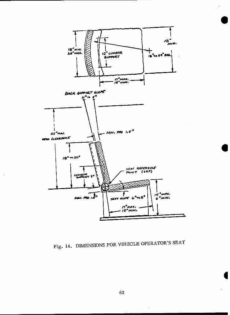
Fig. 14. DIMENSIONS FOR VEHICLE OPERATOR'S SEAT
62
O SEATING
1. Seating for vehicle operators should follow the dimensions recommended inFigure 14.
2. If the seat's height above the floor is variable, requirements for leg roomand foot rest will also vary. When the seat is adjusted higher, there will be moreleg room and larger foot-rest angles.
3. Seats should adjust at least four inches in the fore -aft direction.
4. Back-rest angle should not be more than 105 degrees from horizontal.
5. If only the lumbar area is supported, the back-rest's angle of tilt should be95 degreesto 100 degrees for operators in an alert position.
6. The seat pan should be flat. It should be made from a rigid material.
7. Seat padding should be kept to a minimum, but it should be resilient enoughto keep the operator's body from contacting the seat bottom during severe vibration.
8. Seat padding made of foam-type material should be adequately ventilated.
9. There should be safety seat belts on all administrative -type vehicles.
10. The front edge of troop seats in the vehicle's cargo area should not behigher than 16 inches from the floor.
11. How deep cargo-area seats should be depends on the vehicle's mission;if personnel must wear packs, the seat should be at least 16 inches deep.
63
TIRES
1. The spare tire and tools for servicing it should be readily available. Oneman should be able to remove and stow a tire with OEM only.
2. Vehicles with air -over -hydraulic brake systems should have a pneumaticoutlet and OEM pressure gauge for adjusting tire pressures.
3. The air hose should be long enough to reach all the tires, including the spare,from the air compressor on the same vehicle or another vehicle.
4. When there is no spare tire, the vehicle should have a "limp-home" device(to temporarily take on the function of the flattened tire) that will permit it to continuetraveling for 50 miles after the tire failure.
5. It should be possible to inflate and check the spare tire with a standard airgauge without removing the spare tire from its mounting.
6. DuaL-wheel tires should be designed so both outer and inner tires can beinflated and checked. Valves should be located so tires can be inflated and checkedwhen they are interchanged.
7. Equipment for stowing and unstowing spare tires should be simple to operate 0and safe to use.
8. It should be possible to remove and replace the spare tire with the vehiclefully loaded.
WINDOWS
1. In addition to the windshield area, closed-cab vehicles should have at leastone glass window or curtained aperture on each side of the driver's compartment.
2. Every bus that seats eight or more passengers should have adequate pro-vision for passengers to escape through windows.
3. Each push-out window or other escape window should be clearly identifiedas such by prominent, legible signs, lettering, or decals. These markings shouldtell how to open the emergency exit.
664
O WINDSHIE LDS
1. Windshields should be flat glass sections wherever possible.
2. When windshields must be curved, the curve radius should be large toreduce distortion.
3. The critical visual area extends to, and often beyond, the vehicle's leftcorner post. It is better to use a narrow corner post -- 1 1/2 to 2 inches -- thanto use a wrap-around windshield which severely distorts important visual areas.
4. Buses should have two sun visors, one to shield each half of the windshield,as standard equipment. Sun visors should be constructed to "fit" the areas theyshield. Designers should especially avoid sun visors that leak light around the edges,which can be more annoying than no shielding at all.
5. Buses should have a strip of transparent filter material (generally green)along the top of the windshield, to reduce glare without totally blocking vision.
. WINDSHIELD WIPERS
1. Use electrically operated windshield wipers, rather than vacuum -operatedwipers.
2. Windshield-wiper motors should be at the bottom of the windshield.
3. Windshield wipers should return to the bottom of the windshield when theyare turned off.
4. There should be an emergency handle for operating the windshield wipersmanually if necessary.
5. Windshield wipers should clean the areas of the windshield that the drivermust see through to operate his vehicle adequately.
65
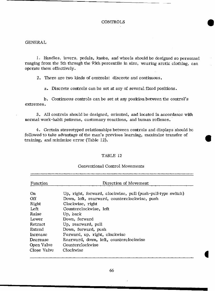
CONTROLS
GENERAL
1. Handles, levers, pedals, knobs, and wheels should be designed so personnelranging from the 5th through the 95th percentile in size, wearing arctic clothing, canoperate them effectively.
2. There are two kinds of controls: discrete and continuous.
a. Discrete controls can be set at any of several fixed positions.
b. Continuous controls can be set at any position between the control'sextremes.
3. All controls should be designed, oriented, and located in accordance withnormal work-habit patterns, customary reactions, and human reflexes.
4. Certain stereotyped relationships between controls and displays should befollowed to take advantage of the man's previous learning, maximize transfer oftraining, and minimize error (Table 12).
TABLE 12
Conventional Control Movements
Function Direction of Movement
On Up, right, forward, clockwise, pull (push-pull-type switch)Off Down, left, rearward, counterclockwise, pushRight Clockwise, rightLeft Counterclockwise, leftRaise Up, backLower Down, forwardRetract Up, rearward, pullExtend Down, forward, pushIncrease Forward, up, right, clockwiseDecrease Rearward, down, left, counterclockwiseOpen Valve CounterclockwiseClose Valve Clockwise
66

5. The direction a control moves in should be consistent with the direction thecontrolled object moves' in.
6. Controls should be distributed so that no one limb will be overburdened.
7. Controls used most frequently should be placed between elbow and shoulderheight. Where "blind" reaching is a requirement, the control should be locatedforward and slightly below elbow height.
8. Operating controls, instruments, and vision devices should be placed sotheir accessibility reflects their importance and frequency of use.
9. The most important controls may not be the ones that are used mostfrequently; therefore, the control's criticality must also be considered.
10. Controls used to perform the same function for different but closelyassociated equipment should be consistent in size and shape.
11. Functionally similar or identical primary controls should be arrangedconsistently from panel to panel and from operating position to operating position.
12. Controls should have labels (on panel or control) that:
a. Identify the control function.
b. Give the method of operation, if it is not obvious.
13. Controls should be coded so they can be identified easily by sight or touch,or both; controls may be distinguished from each other by color, size, shape, orlocation.
14. Using one control should not interfere with using another control unlessthey are purposely interlocked in sequence.
15. Controls should be designed and located so that they cannot be operatedaccidentally.
16. When operating critical controls can be dangerous to equipment orpersonnel, the controls should be guarded appropriately to prevent accidentaloperation.
67
17. Several methods can be recommended for guarding a control againstaccidental operation:
a. Separate it from the area used in the normal sequence of controlmovements.
b. Recess it or place physical barriers around it.
c. Cover it.
d. Interlock it so personnel must make an extra movement to operate it,or operate another control first.
e. Select controls that can be operated only by definite or sustained effort.
18. With proportional controls, including engine throttles, the force and move -ment of the control should parallel the action of the device which is controlled.
19. Proportional controls should not have off positions (dead spots), but controlaction may be disproportionately rapid where settings are not critical, or dispropor-tionately slow where personnel must make fine adjustments.
20. Controls that are located and operated conventionally should have con-
ventional purposes. Also, they must not require peculiar or unique coordinationfor proper, safe operation (e.g., brakes or shift).
21. Control locations and movements should be consistent for all the equipmentthe operator uses. There should be a logical relation between a control's location andmovement, and the action of the equipment it controls.
22. Control operations should require a minimum of movements, particularlywith gear shifting.
23. In successive control movements, the operator's hand should pass easilyfrom sequence to sequence with a minimum change in position or direction.
24. Controls used in a rapid sequence should all operate in the same direction.
25. Control settings should be easy to find and identify.
26. Control knobs should be placed where personnel can operate them without
covering associated indicators, particularly if operators must wear arctic clothing.
27. Control reference positions, such as neutral or maximum limits, should beindicated positively, so they are obvious even under blackout conditions.
I68
28. Discrete controls, such as the gear-ratio selectors, should be marked soW that at least every other step is identified.
29. Hand-operated controls should be positioned so they can be operated easily.There should be clearance for inserting and removing hands and for operating controlswhile wearing arctic mittens.
30. Performance envelopes -- the three-dimensional spaces an operator needsto perform assigned tasks -- must be adequate.
31. Neither the operator's use of controls nor their proper functioning shouldbe affected detrimentally by the vibration of the vehicle.
32. Mechanical transmission controls, such as gear-shifting and parking-brakecontrols, should not be affected by dirt, mud, or ice.
33. Manual steering should be adequate for the driver to stop the vehicle safelyand drive it slowly without any power assist.
Considerations in Selecting Controls
0 1. It is important to consider two basic factors in designing or selectingcontrol devices:
a. Compatibility between the control's movement and location and thoseof the element it controls.
b. The operator's efficiency in using combinations of controls and displays.
2. When the primary considerations in selecting a control are its operatingforce and range of settings, use the recommendations in Table 13.
69
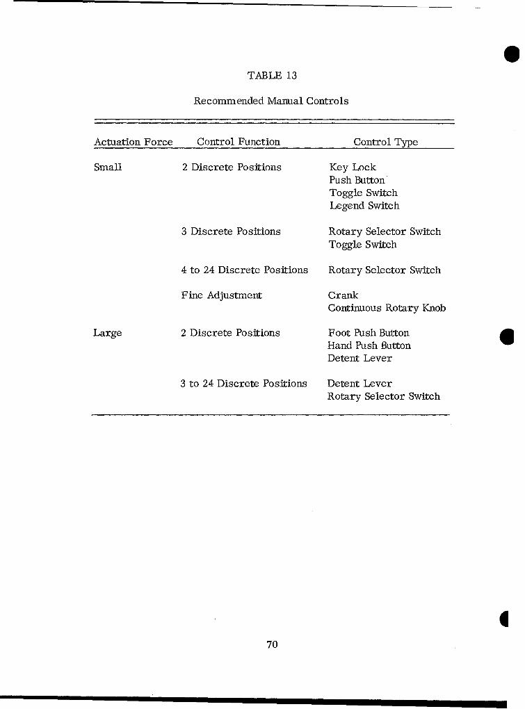
STABLE 13
Recommended Manual Controls
Actuation Force Control Function Control Type
Small 2 Discrete Positions Key LockPush Button
Toggle SwitchLegend Switch
3 Discrete Positions Rotary Selector SwitchToggle Switch
4 to 24 Discrete Positions Rotary Selector Switch
Fine Adjustment CrankContinuous Rotary Knob
Large 2 Discrete Positions Foot Push ButtonHand Push ButtonDetent Lever
3 to 24 Discrete Positions Detent LeverRotary Selector Switch
770
3. The basic information designers need to select the proper control willinclude:
a. The control's function, purpose, and importance to the system; thenature of the controlled object; the type of change to be made, and its extent, direction,and rate of change.
b. The task's requirements -- precision, speed, range, and force requiredto use the control; and how the system is affected by sacrificing in one of these areasto improve another.
c. The information the operator needs, including his requirements forlocating and identifying the control, determining its setting, and sensing any changein its setting.
d. The amount and location of space where the control can be placed.
e. The importance of locating the control in a certain position for propergrouping or proper association with other controls and displays.
4. Hand-operated controls should be used for rapid or precise adjustments.
5. When operators must make precise settings over a wide range, use multi-turn controls.
6. When the controlled object can be adjusted only in a limited number ofdiscrete steps, use discrete -adjustment (detent) controls, rather than continuous-adjustment (non-detent) controls.
7. Controls may be combined to aid sequential or simultaneous operation, toreduce reaching, or to save space. However, designers should minimize the possi-bility of accidental operation.
8. Use foot -operated controls when the man must apply large or continuousforward forces. There should not be more than two foot controls, no matter howsimple, for each foot.
71
MANIPULATION AND SEPARATION OF CONTROLS
1. The driver's control mechanisms should be located on the left side of the cab.
2. The driver should have support if he must make fine or continuous adjust-ments:
a. At the elbow (for gross hand movements).
b. At the forearm (for fine hand movements).
c. At the wrist (for finger movements).
3. When the operator uses controls to supervise an operation, locate themwhere he can supervise continuously while he operates them.
4. How far controls should be separated depends on many factors:
a. Whether the controls are used sequentially or simultaneously.
b. Size of the control.
c. Range over which the control travels. 0d. Cues available for judging the control's setting. (Location deserves
special consideration when the operator's vision is restricted.)
e. How quickly operators must locate and activate the control.
f. How much vibration there is in the operator's compartment or area.
g. Kind of grasp required to operate the control (fingers versus hand grasp).
h. Operator encumbrances (gloves, harnesses, etc.).
i. Likelihood and consequences of operating controls accidentally.
j. Amount of force required to operate controls.
5. Individual control positions depend partly on how they are used, as well ason restrictive garments, harnesses, belts, gloves, etc.
772
S6. For blind locating -- that is, finding and grasping the control without seeingit -- individual controls on a panel must be separated at least five inches if they arein the optimum reaching area directly in front of the operator.
7. When controls are at the man's farthest reach and he must locate themblindly, they should be as far apart as possible within a maximum of 12 inches.
8. When the man can use incidental or casual visual cues to find controls, andhe uses them in random time sequence, with just one hand, the separations betweenthem should be as follows:
a. Minimum separation = two inches.
b. Desired separation = four inches.
c. These separations are measured between the nearest edges of twocontrols.
d. When the man must operate a functional group of several levers at once,with one hand, the end levers must not be more than six inches apart.
9. The operator should be able to manipulate the following controls from hisW normal driving position without strain: steering controls, gear-selection levers,
engine controls, brake controls, rear-view mirror adjustment, clutch, andcommunication controls.
10. The steering wheel should be positioned for easiest operation. There shouldbe at least four inches between its outer edge and the nearest projection from vehicleor equipment.
11. Design foot pedals so an operator can rest his foot on them withoutoperating them.
DESIGN CHARACTERISTICS
Design characteristics for controls are described in Figures 15 through 23and Tables 14 through 22.
73
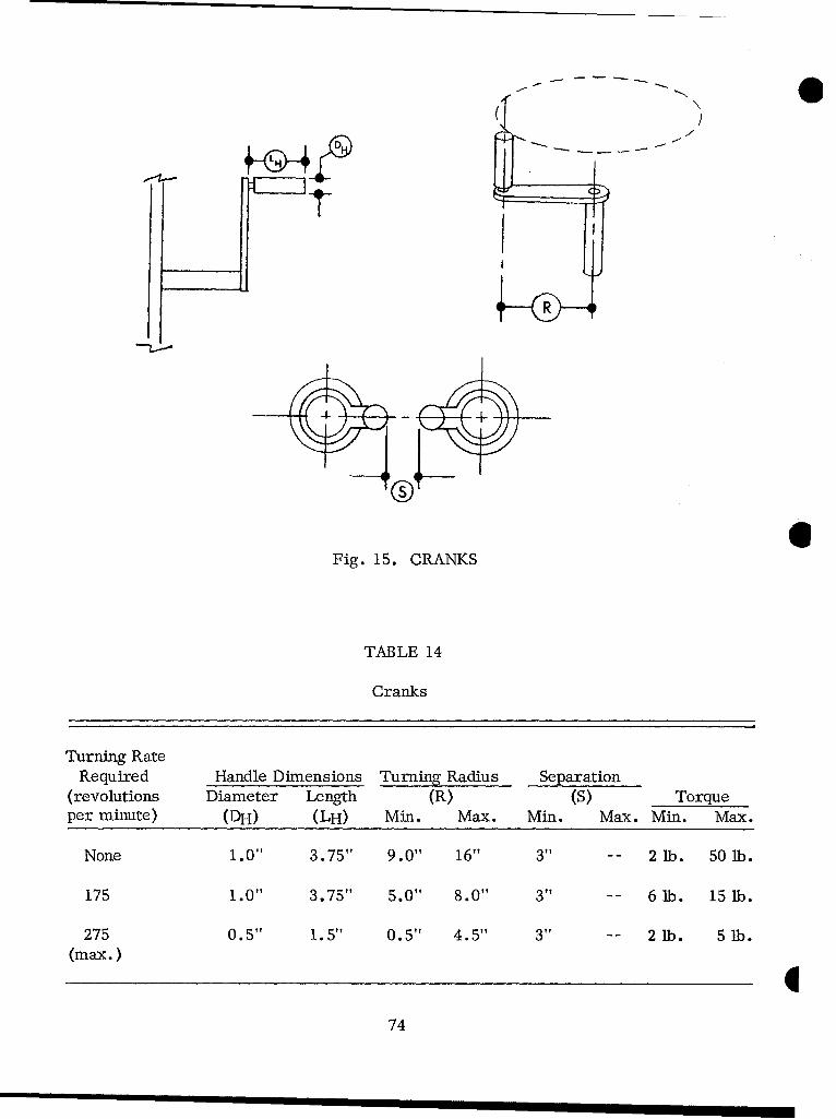
,-4-
©G
Fig. 15. CRANKS
TABLE 14
Cranks
Turning RateRequired Handle Dimensions Turning Radius Separation
(revolutions Diameter Length (R) (S) Torqueper minute) (DH) (LH) Min. Max. Min. Max. Min. Max.
None 1.0" 3.75" 9.0" 16" 3" -- 2 lb. 50 lb.
175 1.0" 3.75" 5.0" 8.0" 3" -- 6 lb. 15 lb.
275 0.5" 1.5" 0.5" 4.5" 3" -- 2 lb. 5 lb.(max.)
774
. HAND CRANKS
1. Cranks should be used primarily when the control must be rotated many times.
2. Handles should be shaped so the area of contact with the hand is as large aspossible.
3. Handles should turn about their shafts freely.
4. For standing operators, handles should be between 36 and 48 inches abovethe floor.
5. If the fastest cranking speed is more than twice the slowest, the operatorshould have a choice of two gear ratios.
6. The outside edge of the crank handle should be at least three inches fromany obstruction.
7. Cranks which must be turned rapidly should be mounted so their turningaxes are between perpendicular to and 60 degrees from the body's frontal plane.
7
75
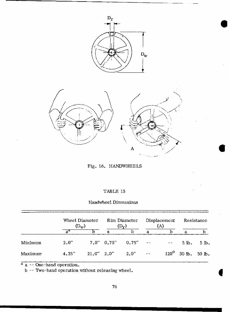
Dr
Dw
A
Fig. 16. HANDWHEELS
TABLE 15
Handwheel Dimensions
Wheel Diameter Rim Diameter Displacement Resistance(Dw) (Dr) (A)
Minimum 2.0"l 7.0" 0.75" 0.75" -- 5 lb. 5 lb.
Maximum. 4.25" 21.0" 2.0" 2.01f 120°0 30 1b. 50 lb.
•a - - One -hand operation.b - - Two -hand operation without releasing wheel.
76
, i I I I I

. HANDWHEELS
1. Use handwheels when the starting or rotational forces are too great for aone-hand control.
2. Handwheels that can be turned only with two hands should not turn morethan 120 degrees.
3. Gripping surfaces should be indented or knurled for more positive grasping.
4. Handwheels should rotate clockwise for on, right, or increase; counter-clockwise for off, left, or decrease.
5. A valve is considered a handwheel.
6. Direction of motion should be indicated on handwheels, or next to them,with double -ended arrows and appropriate legends.
7. Handwheel-type valves should operate conventionally. Direction of move -ment should be shown by double -ended arrows, with the arrow tips marked "open"
and "close."
8. All valve handles should have labels that clearly indicate their functions,as well as the direction of movement.
9. If a handwheel interferes with vision, and if it turns one full revolution orless, the part of it that is not needed for firm hand grasp may be cut away.
10. A spinner handle may be attached to the handwheel if many rotations arerequired.
11. Use multirotation controls for high precision over a wide range of adjust -ments.
12. Handwheel dimensions should be as shown in Table 15.
777
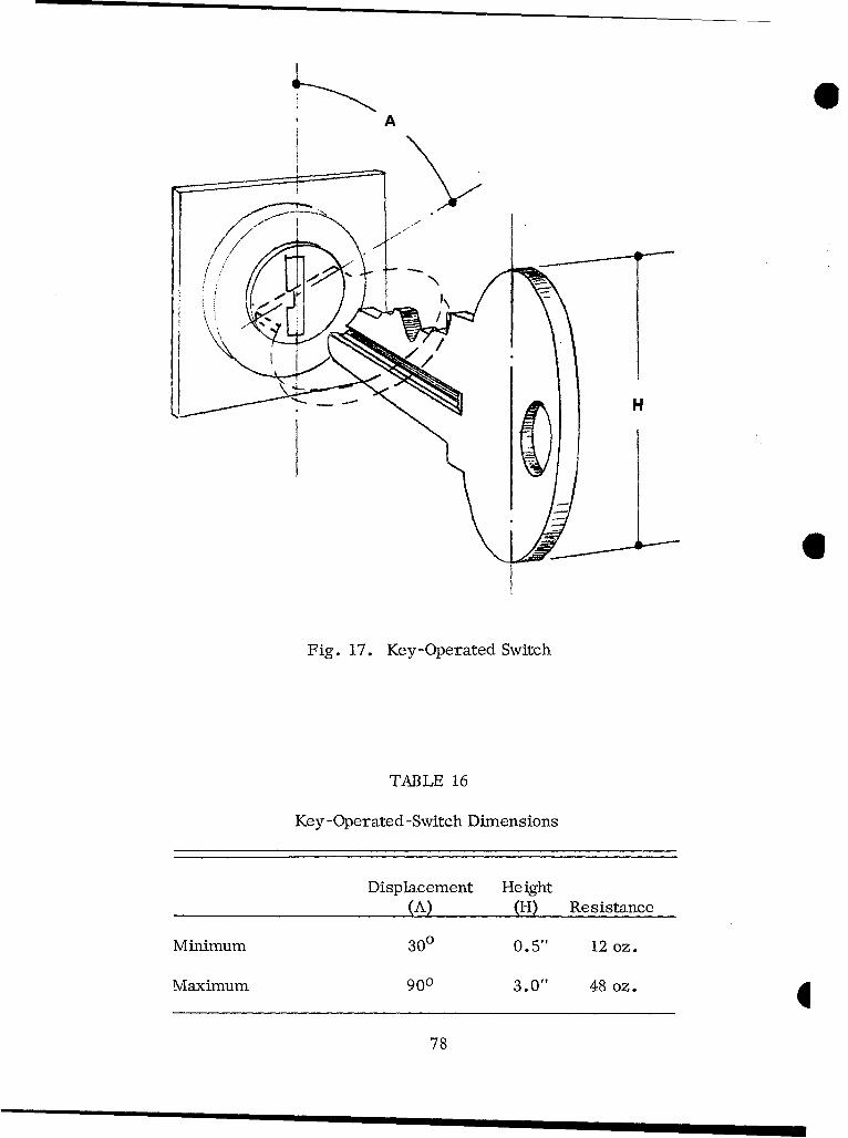
A
1/1
N
/H
Fig. 17. Key-Operated Switch
TABLE 16
Key -Operated -Switch Dimensions
Displacement He ight(A) (H) Resistance
Minimum 300 0. 5" 12 oz.
Maximum 900 3.0" 48 oz.
78

O KEY-OPERATED SWITCH
1. Keys should be shaped so the proper way to insert them is obvious.
2. Keys with a single row of teeth should be inserted into the lock with theteeth pointing up or forward.
3. If keys have teeth on both edges, they should fit the lock with either side up.
4. Locks should be oriented so the key's vertical position is the off position.
5. Operators should not be able to remove the key from the lock unless theswitch is turned off.
6. "On" and "off' positions should be labeled.
79
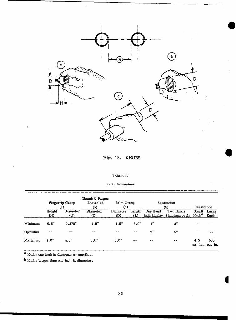
0 0
D D
H- D
Fig. 18. KNOBS
TABLE 17
Knob Dimensions
Thumb & FingerFingertip Grasp Encircled Palm Grasp Separation
(a) (b) (C) (S) ResistanceHeight Diameter Diameter Diameter Length One Hand Two Hands Small Large
(H) (D) (D) (D) (L) Individually Simultaneously Knoba Knobb
Minimum 0.5" 0.375" 1.0" 1.5" 3.0" 1" 3"
Optimum - - -- -- -- -- 2" 5"-
Maximum 1.0" 4.0" 3.0" 3.0" - . ..-- 4.5 6.0oz. in. oz. in.
a Knobs one inch in diameter or smaller.
b Knobs larger than one inch in diameter.
880
O KNOBS
1. Knobs or continuous rotary controls are used to make continuous changesor adjustments.
2. Use knobs where operators must make precise, accurate adjustments of acontinuous variable with little force.
3. Knob diameters should be larger when it takes more force to operate thecontrol. When two or more knobs are mounted concentrically on the same shaft,use the larger knob for fine adjustments and the smaller knobs for coarse adjust -ments.
4. Knobs should be serrated or knurled so the operator's fingers will not slip.
5. Knurled and serrated knobs should be designed so that, if the shaft sticks,the operator will not injure his hands.
6. Knobs which perform the same function should have the same shape.
7. Knobs should have enough resistance that inadvertent touching or accidental* forces like vibration will not change settings.
8. On geared-down vernier knobs and indicators, like those for tuning radios,the pointer should move at least 1. 5 inches for every complete revolution of the knob.
9. Choke and throttle controls should have diameters between 3/4 inch and2 1/2 inches, with a resistance not to exceed two pounds.
81
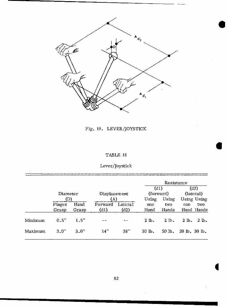
A d
Fig. 19. LEVER/JOYSTICK
6TABLE 18
Lever/Joystick
Resistance(dl) (d2)
Diameter Displacement (forward) (lateral)(D) (A) Using Using Using Using
Finger Hand Forward Lateral one two one twoGrasp Grasp (dl) (d2) Hand Hands Hand Hands
Minimum 0.5" 1.5" 2 lb. 2 lb. 2 lb. 2 lb.
Maximum 3.0" 3.0" 14" 38" 30 lb. 50 lb. 20 lb. 30 lb.
882
.A LEVER/JOYSTICK
1. Use levers for. large displacements or for applying large amounts of force.
2. When levers are close together and may be confused, the lever handlesshould be coded by shape.
3. When levers are mounted perpendicular to the floor, their handles shouldbe between the operator's waist and shoulders.
4. When levers are mounted parallel to the floor, their handles should be28 inches abcve the floor, where a standing operator can exert his greatest liftingforce.
5. For greatest accuracy, the operator should push levers, rather than pullthem.
6. When the man must operate a lever mounted in front of him quickly, itshould move in a fore -aft direction.
7. When a lever must move from side to side, right-handed men can exert* more force pushing leftward with their right hands.
8. When a group of levers in front of the operator pivots about in a common
axis, or relatively close axes, all the levers should move in a fore -and-aft direction.
9. Discrete -position levers should have detents.
10. If men must make fine adjustments with small levers (e.g., joysticks),they should have support:
a. Elbow support for gross hand movements.
b. Forearm support for small hand movements.
c. Wrist support for precise finger movements.
83
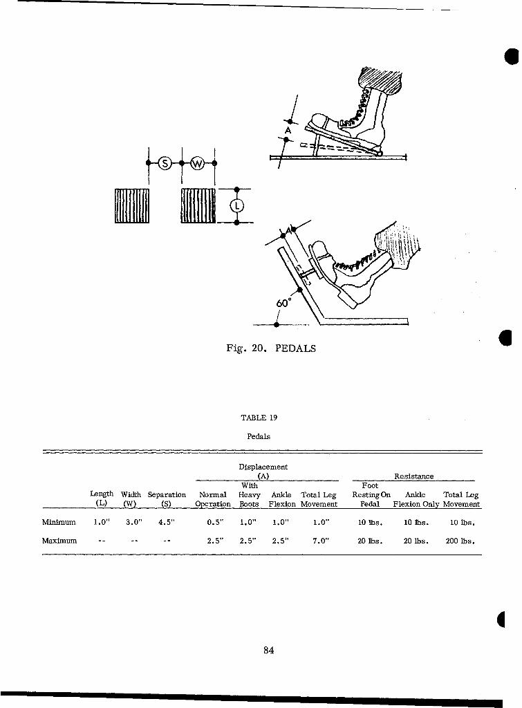
A
60
Fig. 20. PEDALS 0
TABLE 19
Pedals
Displacement(A) Resistance
With FootLength Width Separation Normal Heavy Ankle Total Leg RestingOn Ankle Total Leg
(L) (W) (S) Operation Boots Flexion Movement Pedal Flexion Only Movement
Minimum 1.0" 3.0" 4.5" 0.5' 1.0" 1.0" 1.0" 10 lbs. 10 lbs. 10 lbs.
Maximum -- -- -- 2.5" 2.5" 2.5" 7.0" 20 lbs. 20 lbs. 200 lbs.
884
O PEDALS
1. Use foot -pedal controls for large displacements or applying a great deal offorce.
2. There should be enough spring tension that an operator can rest the weightof his foot on the pedal without operating it.
3. The operator's leg motion should be simple and direct; it should not requiredelicate or complex movements.
"4. There should be a non-skid surface on the face of the pedal and on the heelplate, or the pedal should be made of ribbed rubber, so the operator's foot will notslip.
5. The accelerator and brake pedal should be at least 4 1/2 inches apart.
6. When the brake pedal is depressed fully, it should project at least 1/4 inchabove the accelerator.
7. For an operator to exert maximum force, his thigh should be 20 degrees*O from horizontal and his knee no more than 165 degrees from horizontal when the pedal
is at the end of its travel.
8. Accelerators should not move more than 20 degrees between idling positionand full depression; slightly more than 1 1/2 inches movement is most desirable.
9. The accelerator's pressure against the operator's foot should, ideally,be 8.8 pounds.
85
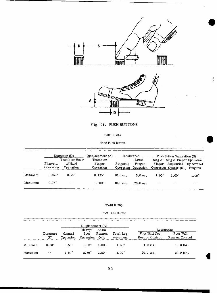
Fig. 21. PUSH BUTTONS
TABLE 20A
Hand Push Button
Diameter (D) Displacement (A) Resistance Push Button Separation (S)Thumb or Heel- Thumb or Little - Single - Single -Finger Operation
Fingertip of-Hand Finger Fingertip Finger Finger Sequential by SeveralOperation Operation Operation Operation Operation Operation Operation Fingers
Minimum 0.375" 0.75" 0. 125" 10.0 oz. 5.0 oz. 1.00" 1.00" 1.00"
Maximum 0.75" -- 1.500" 40.0 oz. 20.0 oz. -- --
TABLE 20B
Foot Push Button
Displacement (A)Heavy - Ankle Resistance
Diameter Normal Boot Flexion Total Leg Foot Will Not Foot Will(D) Operation Operation Only Movement Rest on Control Rest on Control
Minimum 0.50" 0.50" 1.00" 1.00" 1.00" 4.0 Ibs. i0.0 lbs.
Maximum -- 2.50" 2.50" 2.50" 4.00" 20.0 lbs. 20.0 lbs.
86
O PUSH BUTTONS
1. Use finger or hand push buttons to make momentary contacts or to activatelocking circuits which are used very frequently.
2. Push buttons should have feedback cues -- a definite feel and an audible
click - - to tell the man that the push button is activated.
3. Push buttons should have an elastic resistance that increases gradually,then suddenly drops when the control is activated.
4. After the man operates a push button, he should get definite feedback(a visual or auditory indication) of the equipment response.
5. Push buttons should have a concave surface that fits the shape of the finger.Flat push buttons, if used at all, should at least have non-slip surfaces.
6. There are several ways to protect push buttons from accidental operation:
a. Channel or cover guards.
b. Flush mounting.
c. Recessed mounting.
d. Mechanical or electro -mechanical interlocks.
e. Button guards.
7. Use foot push buttons if the operator will probably be using both hands whenhe needs to operate the push button.
8. Foot push buttons are apt to be operated accidentally; avoid using foot pushbuttons if inadvertent operation can have serious consequences.
87
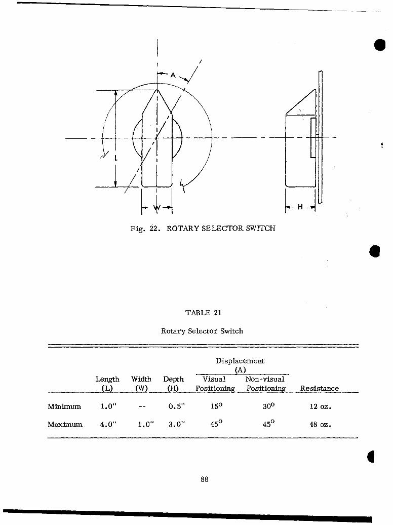
0
//
LLJ~H4
Fig. 22. ROTARY SELECTOR SWITCH
6
TABLE 21
Rotary Selector Switch
Displacement(A)
Length Width Depth Visual Non-visual(L) (W) (H) Positioning Positioning Resistance
Minimum 1.0" 0.5" 150 300 12 oz.
Maximum 4.0" 1.0" 3.0" 450 450 48 oz.
888
. ROTARY SELECTOR SWITCH
1. Rotary selector switches should not have positions that are 180 degreesapart; such positions could be confused if the operator looked at the wrong side of theknob.
2. Switch positions should be between 15 degrees and 45 degrees from eachother.
3. If operators must set rotary selectors without seeing them, the positionsshould not be closer than 30 degrees.
4. Switches should be designed so their detents offer enough resistance tomovement that settings can be made by feel, without looking at them.
5. No rotary selector should have more than 24 positions.
'6. There should be stops at both ends of the range of positions, unless theselector switch itcontinuously sequenced through 360 degrees.
7. Turning a selector switch clockwise should increase the numerical orS alphabetical value associated with it.
8. Rotary selector switches should be designed so they cannot stop betweenpositions.
9. Knobs on rotary selector switches should have pointers that move againsta fixed scale.
10. Moving-pointer knobs should be bar-shaped, with parallel sides;
the index end should taper to a point.
11. The pointer knob should be close to the scale, to minimize parallax.
12. The resistance of selector switches should be measured at the tip of theknob's pointer.
89
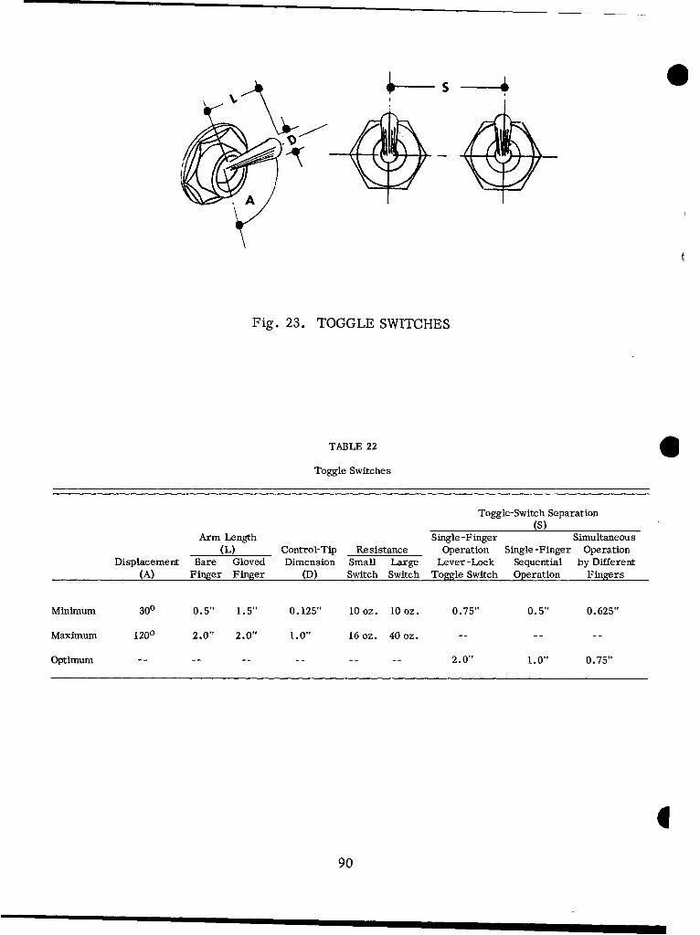
AA
Fig. 23. TOGGLE SWITCHES
TABLE 22
Toggle Switches
Toggle-Switch Separation(S)
Arm Length Single-Finger Simultaneous(L) Control-Tip Resistance Operation Single -Finger Operation
Displacement Bare Gloved Dimension Small Large Lever-Lock Sequential by Different(A) Finger Finger (D) Switch Switch Toggle Switch Operation Fingers
Minimum 300 0.5", 1.5", 0. 125" 10 oz. 10 oz. 0.75" 0.5", 0.625"
Maximum 1200 2.0" 2.0" 1.0"1 16 oz. 40 oz. -...
Optimum ... ... .2.0" 1.0", 0. 75"
90
. TOGGLE SWITCHES
1. Toggle switches should have snap-action contacts and an audible click.
2. When toggle switches are used for momentary contacts, they should be
spring-loaded to return to the off or neutral position.
3. If other displays do not give a positive indication of circuit status, toggleswitches should be accompanied by pilot lights that do so.
4. If an indicator light accompanies a toggle switch, the light should be abovethe toggle switch if possible, or to the left of it.
5. Toggle switches should be oriented vertically, with "on" in the up positionand "off" in the down position.
6. Toggle switches should be mounted horizontally only to make them consistentwith the orientation of controlled functions or equipment.
7. If a toggle switch must be oriented horizontally, the "on" position shouldbe at the right, and the "off" position at the left.
8. Critical toggle switches should have guards -- channel, recess, ring, orcomplete cover -- to protect them from accidental operation.
9. A toggle switch's resistance should increase slowly until it makes contact,then drop to zero as the switch snaps into position (except for momentary contactswitches).
10. Toggle switches should be designed so they cannot stop between positions.
11. If space is severely limited, three -position toggle switches may be usedinstead of rotary selector switches.
12. Three -position toggle switches should not be used for critical systemfunctions.
13. Three-position toggle switches can be used to make momentary contacts,snapping back to the off or neutral position when not manually controlled.
91
DISPLAYS
GENERAL REQUIREMENTS
1. In designing any equipment item that people must operate, giving theminformation about equipment status is always a prime consideration. Almost all ofthe operator's decisions and actions depend on the information which is presentedto him.
2. Selecting or designing a display requires thorough knowledge of the kind,amount, and accuracy of information the operator will require.
3. All displays should conform to these general guidelines:
a. Display only the information that is essential for adequate job perform-ance.
b. Display information only as accurately as the operator's decisions andcontrol actions require.
c. Present information in such a way that any failure or malfunction in the 6display or its circuitry will be obvious immediately.
d. Present data in the most direct, simple, understandable and usableform possible.
e. Arrange displays so the operator can locate and identify them easily,without unnecessary searching.
f. Group displays functionally or sequentially so the operator can use themmore easily.
g. Make sure that all displays are properly illuminated, coded, and labeledby their functions.
992
4. Follow the scale-marking and numbering practices below, to keep the systemconsistent and to maximize legibility:
a. Whenever appropriate, scales should start at zero.
b. Scale graduations should progress by 1 or 5 units, or decimal multiplesthereof (e.g., 10 and 50, or .01 and .05). Graduations of 2 and 20 units may also beused.
c. Numbers should increase from left to right, from bottom to top, orclockwise.
d. Major scale graduations should represent whole numbers, unlessmeasurements are normally.expressed in decimals.
e. There should never be more than nine minor or intermediate marks,and fewer where possible.
f. There should be as much visual contrast as possible between the scale's
face and its markings.
g. On stationary scales, numbers should be upright (never tilted).
h. On moving scales, numbers should be oriented so they will be uprightwhen they are at the reading position.
i. Displays should be designed so pointers will just meet, but not overlap,the shortest graduation marks.
j. Space should be left to enter calibration data on instruments withoutreducing the dial's readability.
k. To minimize parallax, mount pointers as close to dial faces as possible.
1. All displays should be constructed, arranged, and mounted so ambientlight will not reflect toward the operator from glass or plastic covers. It isespecially important to consider reflections when panels slant away from the operator.
m. Use linear scales, rather than non-linear scales, wherever possible.
n. If operators have to interpolate, they must be able to interpolateaccurately enough to meet system requirements.
93
5. Design displays so failures in the display or its circuitry will be obvious.If a display or its circuitry fails, it should not cause associated equipment to fail also.
6. Do not combine information used in different activities (e.g., operation andtrouble -shooting) into a single display unless the activities are comparable andactually require the same information.
7. Arrange displays consistently throughout the system (except as required byother provisions in this section).
8. The displays that are used most often should be grouped together (unlessother provisions in this section require separating them).
0
94

O CRITERIA FOR CHOOSING TYPES OF DISPLAYS
1. Use dials, scales, gauges, or meters:
a. To indicate direction of movement or orientation in space.
b. To show increasing or decreasing trends of the values the instrumentmeasures.
c. When only an approximate reading is needed.
d. For checking readings periodically, rather than continuous monitoring.
2. Use dichotomous (two-valued) indicators:
a. To indicate go-no-go situations qualitatively, on-off status, malfunctions,emergency warnings (use flashing signals), inoperative equipment, cautions, and theoperability of separate components.
b. For especially critical information, illuminate the legends themselves(e.g., use legend lights -- words or numbers that are lighted from behind).
3. Use auditory displays (buzzers, bells, etc.):
a. As emergency or warning devices.
b. When it is important for the operator to react quickly.
4. Use auditory displays with, or instead of, lights:
a. When lights might not be noticed under unusual environmental lighting.
b. When the operator is already busy monitoring lights, dials, counters,and scopes.
c. When critical conditions justify multiple signals (warning, emergency,malfunction).
d. For extreme redundancy.
95
INDICATOR LIGHTS
1. At present, there are two general types of transilluminated indicators:simple indicator lights (e.g., pilot lights, bull's-eye lights, jewel lights, etc.),and single - and multiple -legend lights. Legend lights give information by lightingmeaningful words, numbers, symbols, or abbreviations. Generally, the principlesdiscussed under Simple Indicator Lights apply also to Legend Lights.
2. Use transilluminated indicators to display qualitative information, andprimarily the information that either requires the operator to respond quickly orcalls his attention to an important condition. Occasionally, they are also used topresent maintenance and adjustment information.
3. If indicator lights are used solely for maintenance and adjustment, theyshould be covered during normal operation, yet readily accessible and visible whenneeded.
4. Master action, master warning and summation lights that indicate the con-dition of an entire subsystem should be separated from lights that show componentstatus. Summation lights should also be larger.
5. Lights should indicate that the equipment has actually made the desiredresponse, not merely that the control has been operated. 6
6. Indicators with flashers should be designed so that, if the flasher fails whenthe light should be flashing, it will light steadily.
7. Use lights and all other indicators sparingly -- display only the informationthat is necessary for effective system operation.
8. For easy maintenance, personnel should be able to replace pilot-light bulbsfrom the front of the display panel without using tools.
9. Panels that will be used outdoors should be designed so reflected sunlightcannot make indicators appear to be illuminated.
10. On displays that will be used at night, scale markings should be illuminatedwith red light (620 millimicrons and above) to maintain night vision.
996
* Simple Indicator Lights
1. Use simple indicator lights whenever legend lights are not specificallyrequired.
2. When using types of indicator lights that have only a single bulb, incorporatea master lamp-test control. However, panels with three lights or less may use press -to-test indicators instead.
3. Where a panel has some indicators with a single bulb and others with morethan one bulb, the master light-test control should test both types.
4. Sifliple round indicator-light fixtures should be spaced far enough apart forunambiguous labeling and convenient bulb removal.
:5. Indicate malfunctions positively, by having them turn on malfunction lights,rather than implying them deviously, by turning off the light that indicates satis -.. fctory operation.
.6. Do not use lights that merely indicate the position of a control unless thecontrol position is not (or cannot) be shown by the control's design and labeling.Use lights to display the equipment's response, not merely a control's position.
7. When a control is associated with a transilluminated indicator, locate theindicator light so it is immediately and unambiguously associated with the control.In most instances, the light should be placed above the control.
8. Auxiliary lights should have brightnesses between 5 and 10 foot-Lamberts.
9. Indicators should not be so bright that they dazzle the operator.
10. When lights are used under varying ambient illumination, there should be adimming control. Its range should be limited so that fully dimmed lights will still bevisible under the brightest expected ambient illumination.
11. Critical indicators should be located within 30 degrees of the normal line ofsight. Warning lights should be built into (or near) the control the operator uses totake action.
12. Indicate personnel or equipment danger with a flashing red light one inch indiameter.
13. Master summation indications for a system or subsystem should be steadyred or green lights one inch in diameter.
14. Indicate all other conditions with steady lights 1/2 inch in diameter.
15. One-inch-diameter lights should be obviously brighter than 1/2-inch-diameterlights.
97
COLOR CODING
Red, green, yellow, blue, and white colors should be in accordance withType I, Aviation Colors of MIL-C-25050.
a. Green
Green should indicate that equipment is operating satisfactorily: intolerance, test OK, ready, etc.
b. White
White should show status - - conditions which are neither satisfactorynor unsatisfactory in themselves -- such as alternative functions and selectionmode, test in progress, etc.
c. Yellow
Yellow should alert an operator to situations that call for caution,recheck, or delay.
d. Red
Red should alert an operator to conditions that make the systeminoperative, e.g., error, no-go, failure, malfunction, danger.
e. Blue
Blue is used as a fifth color when necessary. It has no general meaning.
FLASH CODING
1. Flashing lights should flash three to five times a second, and their "on"and "off" times should be approximately equal.
2. Flashing Red -- Flashing red should indicate extreme dangers to equip-ment or personnel.
3. Flashing White -- Flashing white should be used as an alerting signal
on communications equipment.
998
MOVING-POINTER FIXED-SCALE INDICATORS
Circular Scales
1. Clockwise pointer movement should give larger readings, as operatorsexpect.
2. To display values ranging from positive through zero to negative, locate thezero point at the nine or twelve o'clock position. Positive values should increase whenthe pointer moves clockwise (to the right), and negative values should increase when
the pointer moves counterclockwise (to the left).
S3. It is generally better to place numerals inside the graduation marks, so the
bezel will not hide them and so the scale can be relatively larger. If space is not'limited, numbers may be placed outside the scale so the pointer will not cover them.
4. Except for multi-revolution, continuous -scale instruments, such as clocks,there should be an obvious gap -- not less than 1 1/2 divisions -- between the twoends of the scale.
SO Non-Linear Scales
Non-linear scales condense a large range into a relatively small space, yetpermit sensitive readings in critical ranges. Where error tolerances are a constantpercentage of the indication, a logarthmic scale is very suitable. However, logarith-mic scales should have as many numbered graduation marks as possible, to minimizeerrors that might result because people are more used to reading linear scales.
Pointers
1. For best legibility, indicators with scales should have pointers that arerelatively wide at the pivot, tapering gradually to a fine tip.
2. Pointer tips should be as wide as the smallest graduation mark.
3. In "edgewise" indicators -- such as rectangular meters with straight scales --
only the tip of the pointer may be visible. If so, it should be distinctive and obvious:a flag, spade, or target pointer.
4. Pointers should be pivoted at the right for vertical scales, and at the bottomfor horizontal scales.
99
5. Pointer tips should never be more than 1/16 inch from the scale graduations. *6. The angle subtended between the pointer tip and the scale's plane should
never be more than 20 degrees.
7. Pointers should meet, but not overlap, the shortest scale -graduation mark.
8. Pointers should not cover scale numbers completely.
9. Pointers should be the same color as the numbers and scale divisions (butsee 3 above).
10. There should not be more than two pointers on a single shaft.
11. Reciprocal pointer ends should be easy to distinguish from each other.
100
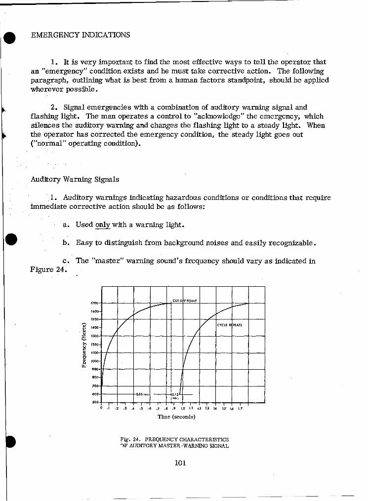
. EMERGENCY INDICATIONS
1. It is very important to find the most effective ways to tell the operator thatan "emergency" condition exists and he must take corrective action. The followingparagraph, outlining what is best from a human factors standpoint, should be appliedwherever possible.
2. Signal emergencies with a combination of auditory warning signal andflashing light. The man operates a control to "acknowledge" the emergency, whichsilences the auditory warning and changes the flashing light to a steady light. Whenthe operator has corrected the emergency condition, the steady light goes out("normal" operating condition).
Auditory Warning Signals
1. Auditory warnings indicating hazardous conditions or conditions that requireimmediate corrective action should be as follows:
a. Used only with a warning light.
b. Easy to distinguish from background noises and easily recognizable.
c. The "master" warning sound's frequency should vary as indicated inFigure 24.
1700-- CUTO F POINT
1600
1500. I
1400 I CYCLE R PEATS1400-
1300-- - __- -
>1 1200-
0) 1100- - - - I1000-
900- - 4--___
7001
70 -ooo- I - - ___
600 - - 0L85,. .1
I SCSoo-
0 .1 .2 .3 .4 .5 .6 .7 .8 .9 1.0 lei L2 1.3 IA 1.1 1.6 1.7
Time (seconds)
Fig. 24. FREQUENCY CHARACTERISTICS")F AUDITORY MASTER-WARNING SIGNAL
101
2. If additional warning sounds are needed, personnel can readily identify thefollowing as different:
a. 1600 + 50 Hz tone, interrupted at a rate of 1 to 10 Hz.
b. 900 + 50 Hz steady tone, plus 1600 ± 50 Hz tone interrupted at a rateof 0 to 1 Hz.
c. 900 - 50 Hz steady tone.
d. 900 + 50 Hz steady tone, plus 400 ± 50 Hz tone interrupted at a rateof 0 to 1 Hz.
e. 400 _ 50 Hz tone, interrupted at a rate of 1 to 10 Hz.
3. Warning signals should be louder than the ambient noise so they can bedetected and identified immediately. In noisy locations, the warning signal shouldbe about 20 dB above the ambient noise level. (See Noise section, page 31.)
4. Warning-signal intensities must be kept as far below the human painthreshold, which is approximately 130 dB, as ambient noise conditions will permit.
5. An auditory signal may be used without an accompanying warning lightwhen there is only one extreme emergency condition (e.g., vehicle on fire, "getout"), but in such cases there should not be any other auditory signals in the vehicle.
1102
* Visual Warning Signals
1. Designers should consider the following guidelines in weighing the physicalcharacteristics and placement of "warning" indicators:
a. For optimum visibility, the master warning indicator should be within30 degrees of the standard line of sight.
b. Emergency indicators should be obviously larger than general statusindicators.
c. An emergency indicator's brightness contrast with the immediate back-ground should be at least 2 to 1.
d. When illuminated, an emergency indicator should be at least as bright
as the brightest light source on the same console.
e. Warning indicators should be colored red (see Indicator Lights, page 96)and located within 60 degrees of the standard line of sight.
f. When there is extreme danger to personnel or equipment, the warningindicator should be flashing red with these'characteristics:
0 (1) Flash rate between three and five pulses per second.
(2) "On" time about equal to "off" time.
(3) If the "flashing" device fails, the light comes on steadily.
(4) Should provide "word" warning (such as DANGER - STOP) wheneverpossible -- and if it does, should be placed within 10 degrees of the standard line ofsight.
(5) If it displays a symbol, instead of a word, the indicator should bewithin 30 degrees of the standard line of sight.
103
CODING
GENERAL
1. Coding helps distinguish controls, indicators, connectors, and other devicesthat perform the same function or are consistently used together. Coding is frequentlyused so various unrelated devices can be distinguished from each other readily.
2. There are many methods of coding; whichever method is selected, it shouldhave a consistent meaning throughout the system.
3. When deciding which kind of coding to use in a particular situation, considerthe following factors:
a. Types of coding already in use.
b. Kinds of information to be coded.
c. Nature of the tasks to be performed and the conditions under which theywill be performed.
d. Number of coding categories each coding method offers (e.g., the numberof different knob shapes available).
e. Space and illumination the various coding methods require.
f. Need for redundant or combination coding.
g. Standardizing coding methods.
104
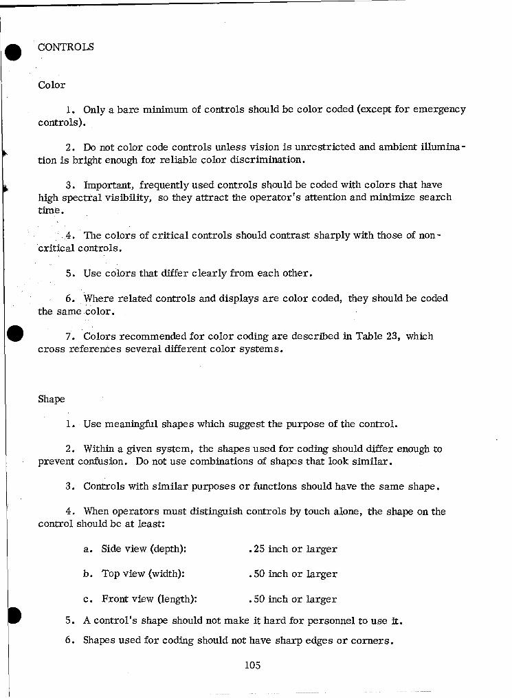
. CONTROLS
Color
1. Only a bare minimum of controls should be color coded (except for emergencycontrols).
2. Do not color code controls unless vision is unrestricted and ambient illumina-tion is bright enough for reliable color discrimination.
3. Important, frequently used controls should be coded with colors that havehigh spectral visibility, so they attract the operator's attention and minimize searchtime.
4. The colors of critical controls should contrast sharply with those of non-critical controls.
5. Use colors that differ clearly from each other.
6. Where related controls and displays are color coded, they should be codedthe same color.
7. Colors recommended for color coding are described in Table 23, whichcross references several different color systems.
Shape
1. Use meaningful shapes which suggest the purpose of the control.
2. Within a given system, the shapes used for coding should differ enough toprevent confusion. Do not use combinations of shapes that look similar.
3. Controls with similar purposes or functions should have the same shape.
4. When operators must distinguish controls by touch alone, the shape on thecontrol should be at least:
a. Side view (depth): .25 inch or larger
b. Top view (width): .50 inch or larger
c. Front view (length): .50 inch or larger
5. A control's shape should not make it hard for personnel to use it.
6. Shapes used for coding should not have sharp edges or corners.
105
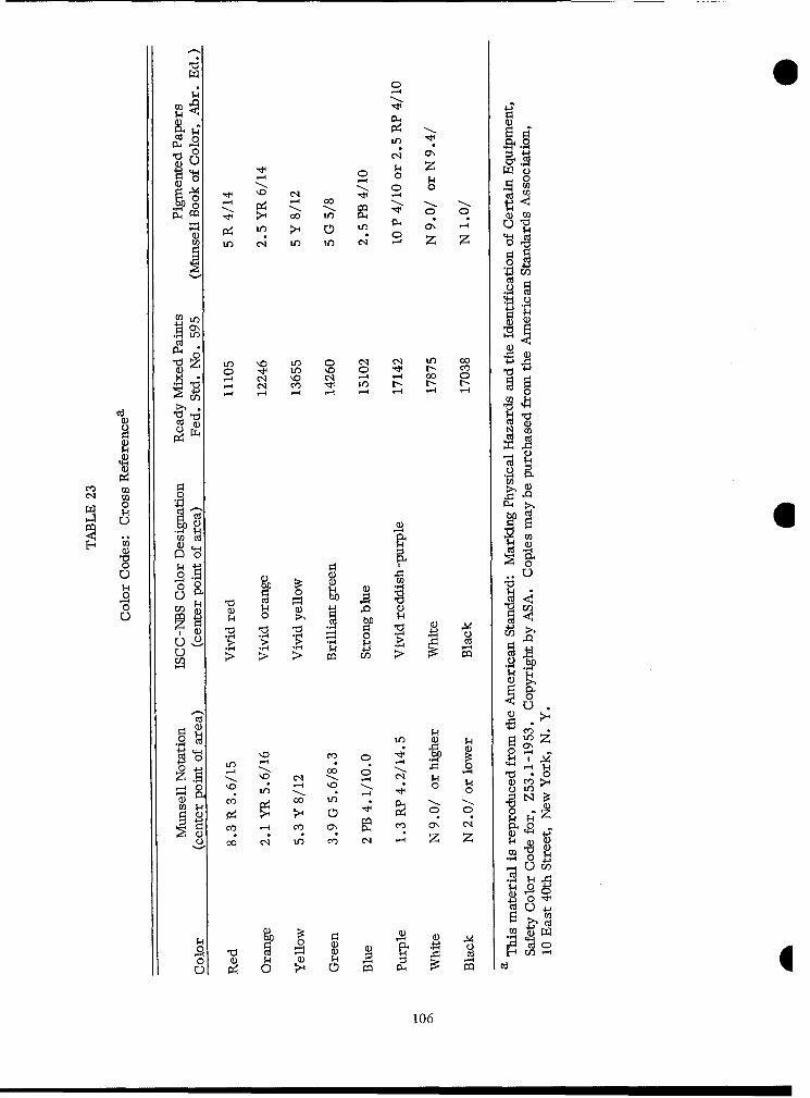
0 C0-4 0 H
0 Cq -44'
000
IA IA 04 \
tr) LO 0A I C1 '4 Zq to 00 4
'~~~Z- IA -4 IA0C1 ~ A 0o ~ A '0 0 '~N w
0Q)
0a) 44 U
oo(1
(Ud
11 ci)
M 000)U
00
00 >4>> 0 0 0 c
\0 00 (N0.-
00 LO _q
00 IA$
0~ 0 p a)0) -0) -: 00 LO
C) C ) 0
O~~~~~ 00ý Zl I 0 C - 0
00 cq U") C) cq z 0N4 0
440 It
CCU4
00
0 (1) N Q) N' -0-0 o H c 0d
106
Size
1. Use size coding when only two or three controls will be coded.
2. Size and shape coding may be combined, since the ability to discriminateshapes is independent of size discrimination.
3. Code consistently when controls have the same function on different items ofequipment.
4. When coding knobs with diameters between 0.5 inch and 4.0 inches by size,each knob should be at least 20 percent larger than the next smaller one.
Location
1. When operators must make blind-positioning movements, the most effectiveway to code controls is by location.
2. Operators discriminate locations more accurately when controls are in frontof them.
3. Location-coded controls should be lower than the operator's shoulder level.
4. Controls in the forward area should be separated about six to eight inchesfor optimum discrimination.
5. When controls are beside or behind the operator, they should be separated12 to 16 inches for effective operation and accurate discrimination.
107
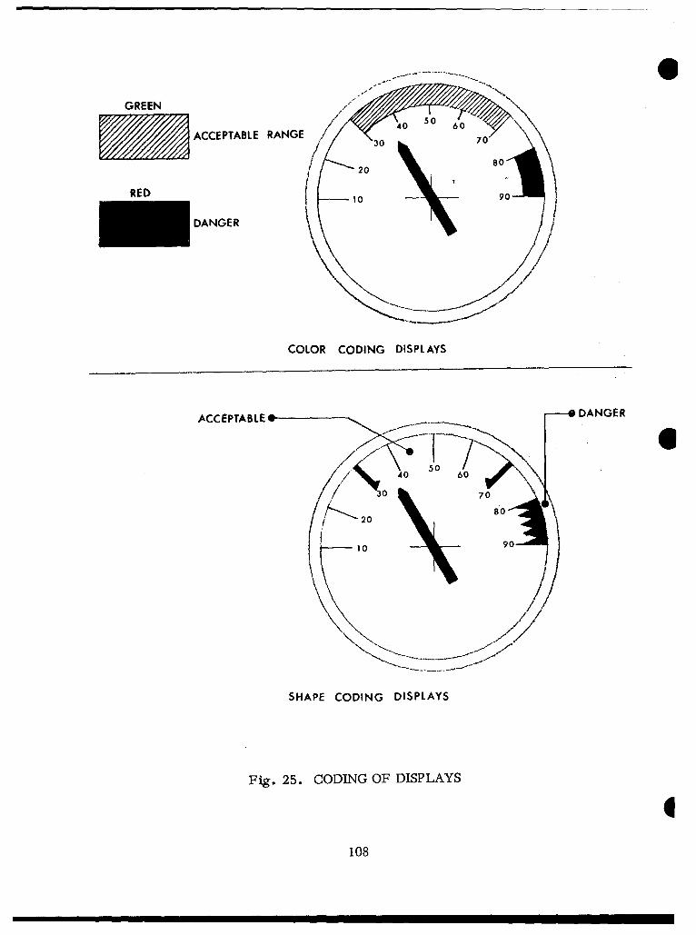
6
GREEN/W
ACCEPTABLE RANGE / "0 70/ 30
S -20 80
RED o10 9
,,, /- DANGER
COLOR CODING DISPLAYS
ACCEPTABLE* 0 DANGER
~30 40 5060•30 707
80
20
10 90
///'
SHAPE CODING DISPLAYS
Fig. 25. CODING OF DISPLAYS
I108

O COLOR BANDING OF DISPLAY SCALE ZONES
1. Use color codes, markings, and bands (Fig. 25) so personnel can readdisplays more effectively:
a. To make it obvious at a glance whether the indication is withinacceptable limits.
b. To make it equally obvious when the indication is a "danger" rangerequiring immediate corrective action.
c. To keep operators from misreading numbers or mistaking a desirednumerical value.
2. Colors often appear different under different types of illumination;unless a display will always be used under white light, do not use color coding.
Shape
1. Although shape -coding displays may occasionally be useful, it is notWO generally recommended.
2. A display's scale zones may be coded with shapes (Fig. 25). The shapesused for coding purposes should be:
a. Easy to learn.
b. Distinguishable under dim illumination.
c. Distinguishable under any color of light.
Size
1. Transilluminated indicator lights that indicate emergency, failure, andmaster summation should be larger than other indicators.
2. All other types of displays may be coded with varying sizes.
109
Location
1. Location coding arranges displays into groups to make them distinguishablefrom each other.
2. Locations may be coded by:
a. Spacing between groups of displays; use horizontal separations wherepossible, rather than vertical separations.
b. Outlining or bordering display groups.
c. Placing display groups on different planes (with respect to the operator).
d. Symmetry.
1
110
O CONDUCTORS
Electrical Conductors
1. The primary method of coding electrical conductors is by colored insulation.Every individual wire in a cable should be color coded over its entire length. Thereare 21 discriminably different patterns of solid colors and solids with striped tracers(Table 24). For coding more than 21 conductors, see MIL STD 686. Several ways ofcoloring wires are, in order of preference:
a. Solid-colored insulation.
b. Solid-colored insulation with colored-stripe tracer.
c. Colored braid insulation with woven tracer.
2. Where conductors are coded with numerals, the numbers should be repeatedat least every two inche.s over the conductor's entire length.
3. Numbered metal tags may also be used to code cables and conductors.
Hydraulic and Pneumatic Conductors
Hydraulic and pneumatic conductors should be coded with numbered metal tags.
111
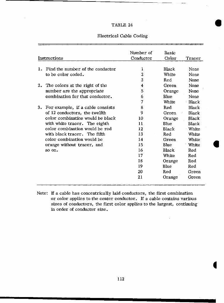
TABLE 24
Electrical Cable Coding
Number of BasicInstructions Conductor Color Tracer
1. Find the number of the conductor I Black Noneto be color coded. 2 White None
3 Red None2. The colors at the right of the 4 Green None
number are the appropriate 5 Orange Nonecombination for that conductor. 6 Blue None
7 White Black3. For example, if a cable consists 8 Red Black
of 12 conductors, the twelfth 9 Green Blackcolor combination would be black 10 Orange Blackwith white tracer. The eighth 11 Blue Blackcolor combination would be red 12 Black Whitewith black tracer. The fifth 13 Red Whitecolor combination would be 14 Green Whiteorange without tracer, and 15 Blue White 0so on. 16 Black Red
17 White Red18 Orange Red19 Blue Red20 Red Green21 Orange Green
Note: If a cable has concentrically laid conductors, the first combinationor color applies to the center conductor. If a cable contains varioussizes of conductors, the first color applies to the largest, continuingin order of conductor size.
112
LABELING
GENERAL
1. Identify things with labels for easy location, reading, or manipulation.The type of labeling depends on a number of factors, such as:
a. How accurately the item must be identified.
b. Time available for reading.
c. Distance between reader and label.
d. Brightness and color of illumination.
2. Labels should conform to these principles:
a. A label should give the user the information he needs to perform his task.
b. Labels should be located consistently throughout the equipment.
c. Labels should use familiar words; avoid overly technical or difficult words.
d. Make labels brief but unambiguous; omit punctuation.
e. Print words so they read horizontally, not vertically.
f. Supplement labeling where necessary with other coding procedures(such as color and shape).
g. Place labels where they can be seen easily, not where other units in theassembly will cover or obscure them.
h. Make labels large enough that the operator can read them easily at hisnormal distance.
i. Generally, use capital letters; however, if the label has several longlines, use upper- and lower-case letters.
j. Use bold-face letters only for short words or phrases that requireemphasis.
k. Place labels on or very near to the item they identify; eliminate anyconfusion with other items and labels.
1. Labeling should be etched or embossed into the surface for durability,rather than stamped, stenciled, or printed. Decals are acceptable, but less desirable.
113
NUMERAL AND LETTER DESIGN
Style
1. The recommended typeface for labeling is Alternate Gothic #2 or anequivalent approved by the procuring activity. The same typeface should be usedconsistently throughout the system.
2. All numerals should be Arabic; avoid Roman numerals.
Height -to -Stroke Width Ratio
Where panel labels are illuminated by ambient or individual illumination,the height-to-stroke width ratio should be within the range 6:1 to 8:1.
Width
1. The average width of characters should be between 65 percent and85 percent of their height.
2. The letters I, M, W, and the numerals 1 and 4, may vary substantiallyfrom the average width. The geometric proportions for these characters aredetermined by the typeface.
1114
*• Spacing and Size*
1. Letters printed from foundry type.
a. Type founders cast their letters so they are automatically spacedproperly when assembled in a composing stick - - so ordinarily printers do not useany spaces between letters. Thus the between-letter spacing is built in, and youhave automatically specified it by your choice of typeface.
b. Spacing between words is not so standard, but it usually is roughlyone-third the point body for material set in caps and lower case - - less for narrowor short letters, and more for wide or tall ones. It is usually about half the pointbody for matarial set in all caps. If copy is justified, the spacing between wordscan be considerably more or less than these averages, and apparently withoutiffecting legibility very much.
c. Spacing between lines is almost purely a matter of judgment -- butit is limited by the fact that two pieces of type can be only so close together,depending on how much of the point body the letters occupy.
2. Lettering should read horizontally, from left to right, and there shouldbe at least 1/8-inch space between lines.
* Type sizes in points give only a rough indication of the heights of characters.
For example, 18 points equals 1/4 inch; but 18-point letters, while cast onbodies 1/4 inch high, will seldom or never be that high. The actual size of18-point characters varies widely from face to face and from foundry to foundry.Unless you have measured the letter heights corresponding to point sizes of agiven face, do not specify lettering by point sizes; specify letter heights infractions of an inch.
1115
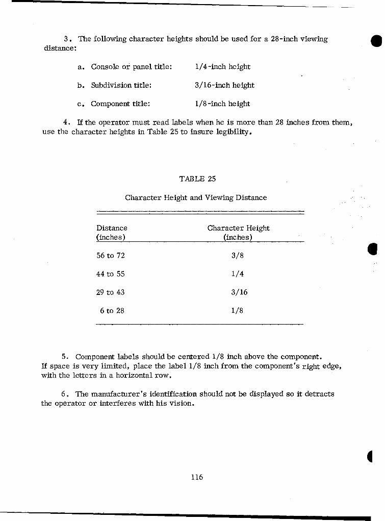
3. The following character heights should be used for a 28-inch viewingdistance:
a. Console or panel title: 1/4-inch height
b. Subdivision title: 3/16-inch height
c. Component title: 1/8 -inch height
4. If the operator must read labels when he is more than 28 inches from them,use the character heights in Table 25 to insure legibility.
TABLE 25
Character Height and Viewing Distance
Distance Character Height(inches) (inches)
56 to 72 3/8 644 to 55 1/4
29 to 43 3/16
6 to 28 1/8
5. Component labels should be centered 1/8 inch above the component.If space is very limited, place the label 1/8 inch from the component's right edge,with the letters in a horizontal row.
6. The manufacturer's identification should not be displayed so it detractsthe operator or interferes with his vision.
1116

. CONTENT
1. Labels should be brief, but not cryptic, ambiguous, or confusing.
2. Use common words or words the operator readily understands and ordinarilyuses. Avoid technical words unless they are necessary to give exact information andthe operator can reasonably be expected to have a working knowledge of them.
3. Avoid abbreviations and symbols if possible. Where space is limited, useMIL STD 12 abbreviations. Symbols, if used at all, should be meaningful and incommon usage.
LABELING FOR IDENTIFICATION
Assemblies
Label assemblies with clearly visible, readable, and meaningful names orsigns. Assembly labels should:
a. Specify the overall system the assembly is a part of.
b. Include the assembly's popular name and function.
c. Include a stock number for requisition purposes.
d. The gross identifying label on an assembly should be located:
(1) Where adjacent assemblies will not obscure it.
(2) On the flattest, most uncluttered surface available.
(3) On a main chassis of the assembly.
(4) Where it will not be removed accidentally, obstructed, ordamaged in handling.
Connectors
Each permanently installed receptacle should have a label indicating type ofoutput and the appropriate connector. This label should be next to the receptacle,aperture, or connector for clear identification.
117

Instruction Plates
1. Consult the latest issue of MIL-P-514 for instruction-plate specifications.
2. Instruction plates should be placed where the operator can see themeasily.
3. Instruction plates should be as brief as clarity allows. Give only theinformation the operator needs - - preferably in diagrammatic form.
4. List instructions in a step-by-step format, rather than in a continuousparagraph.
5. Instructions should read from left to right.
6. Orient instructional diagrams so they relate logically to the objects theypertain to; locate them in conspicuous places on or near controls.
7. Indicate control movements with arrows parallel to the directions thecontrols actually move.
8. Instruction plates should be printed in white letters on a black background.The black color should be 37038, Federal Standard 595, or an approved equivalent.
9. Caution or warning plates should be printed in black letters on a yellowbackground. The black color should be 37038, Federal Standard 595, the yellowcolor should be 23538 or 23655, Federal Standard 595.
10. Information-plate lettering should be 12- to 14-point size, with titles in24-point letters.
11. Avoid vertical lettering.
12. Instruction plates for transmissions should show maximum permissiblerpm and/or road speed for each gear range.
13. Gearshift instruction plates should give operating positions of shift handlesfor transmission and transfer-case mechanisms.
14. Furnish instruction plates for all power take offs and winch controls.
I118
Lift Points
1. Mark lift or hoist points clearly, indicating weight or stress limitations.
2. Label lift or hoist points at the point of lift, not on removable parts of thebody member (e.g., protective cover, access covers, etc.) that may be separatedfrom the lift point.
Safety and Hazards
Wherever possible, design equipment so it does not present hazards topersonnel or equipment. If hazards are unavoidable, display warning signsprominently. These safety labels should be brief and uncluttered -- generallyno more than two or three words.
119
COMMUNICATIONS
GENERAL
1. Voice communication is the most common method of requesting and providing
information. In military systems, communications may be transmitted in several ways:
a. Electrically, using radio or telephone.
b. Operator to operator.
c. Visual (lights, flags).
d. Buzzers and other auditory signals.
2. Communication equipment should be located to maximize its audibility in thearea it serves. When two or more auditory displays (i.e., telephone, radio, intercom,etc.) are in the same area, their sounds should be distinctive.
3. Provide for communication between the vehicle operator and personnel in thecargo or passenger compartment (e.g., a momentary push button in cargo area con-nected to a light on the dashboard).
120
. ' RADIO SET
1. The radio set should be located where the crew and the rest of the systemare least likely to damage it.
2. Do not locate the radio set where it will interfere with the crew's normalmovements or be a hazard to them.
3. The radio operator should be able to see the radio's control panel.
4. The radio operator should be able to reach the radio control panel tochange frequencies.
5. When the radio has devices to protect it from damages like overloadsand excessive heating, provide access points for checking these devices visually.
6. Maintenance personnel should be able to discharge capacitors beforeworking on high-voltage circuits.
7. Protect all bare wires and terminals in medium -voltage or high-voltagecircuits so they will not be short circuited or grounded, and so operating or
*0 maintenance personnel cannot touch them accidentally.
8. All exposed metal parts should be at ground potential.
RADIO ANTENNA
Locate radio antennas to minimize radio frequency (RF) hazards to personnel.
121
CONTROL BOX
1. Radio control boxes should be located so all controls are easily accessible.
2. Locate control boxes so they will not interfere with the crew's normal move -ments or be a hazard to them.
3. Do not locate control boxes where they can be used as steps or footrests.
4. Position control boxes so handset or microphone cables cannot be damaged byrotating or moving linkages.
5. Control boxes must be within the operating length of the standard audioaccessories used with radio -interphone equipment. Control boxes should not be morethan 30 inches from a crewman's normal working area.
6. Signal or warning lights on control units should be within the responsiblecrewman's field of vision.
AUDIO ACCESSORIES 6
1. Provide stowage hooks near each crew member so he can store audioaccessories when he is not using them.
2. Locate hooks where they will not interfere with the crew's normal movements.
CABLE ROUTING
1. Route interconnecting communication cables so crew members will not usethem as handholds or steps. If necessary, place protective guards over the cables.
2. Route all interconnecting cables neatly, without slack or loops. Space cableclamps about 12 inches apart.
i122
STOWAGE
GENERAL
1. Secure stowed items in stowage boxes so they will not be damaged duringcross-country operation. If stowage boxes cannot be provided, retain items withstraps or brackets.
2. If items are inflammable or may be damaged by leaking lubricants, fuels,or water, stow them so they will have reasonable protection from engines, generators,exhaust components, etc.
3. All stowage locations should drain adequately when the vehicle is on levelground. Arrange drain holes so normal stowage will not block them.
4. Consider potential climatic effects in locating stowage space for items thatcrew members must wear.
5. There must be stowage space for life-support equipment (e.g., sleepingIW bags, arctic clothing, rations, etc.).
6. Consider climatic factors in locating items to make sure personnel will be
able to operate them after they have been exposed to the environment.
7. Provide ways to safeguard all stowed equipment from pilferage.
8. Locate floor stowage boxes where they will not interfere with the crew'sfooting.
9. Stow items that are critical to the mission within easy reach of crew members.
10. Label stowage locations clearly and permanently to show where each itemshould be stored.
11. Wherever necessary, provide readily accessible stowage for fireextinguisher(s).
12. Where feasible, make stowage boxes part of the vehicle, rather thanattachments.
123
INTERFERENCE
1. Stowed items should not interfere with the crew's entrance, exit, escape,movement, or operations.
2. Stowage should not interfere with system functions.
3. Design stowage so personnel can remove and replace a stowed item withouthaving to remove or replace other stowed items or system components.
4. The 5th through 95th percentile men, wearing gloves, should be able tostow and unstow all stowed items without assuming unnatural positions.
USE OF STOWAGE SPACE
1. The accessibility and location of stowed equipment should reflect itsfunction and use.
2. Items a particular crew member uses for his task requirement should 0be stowed conveniently and accessibly within his station's functional area.
3. Wherever possible, use dead space for stowing items.
4. There should be stowage for items like individual weapons, small-armsammunition, etc.
RETAINING
1. Retaining devices should be simple, and they should be designed so theycan be replaced quickly.
2. Design retainers so items can be stowed and unstowed by hand; no toolsshould be required.
3. Design retainers so items can be stowed and unstowed under all environ-
mental conditions.
1124
OI STOWAGE BOXES -- DOORS AND COVERS
1. Unless access covers or doors are completely removable, design them sothey will stay open, once opened; unless gravity holds them open, use built-in bracesor latches.
2. If instructions about a component in a box are on the door of the box, orientthe lettering so it can be read when the door is open.
3. If personnel must have access to the rear of sliding, rotating, or hingedunits, design them so they open or rotate their full distance freely and remain "open"by themselves.
. 4. It should be obvious how to open a cover or door; if it is not, attach apermanent instruction plate to the outside of the cover.
5. It should be obvious when a cover or door is in place but not secured.
6. Avoid using sharp edges and corners on doors, covers, and other exposedsurfaces.
* 7. To simplify reinstalling removable inspection-access doors, either makev them interchangeable or use sizes and shapes which will make their proper position
obvious.
8. Obstructions (i.e., OEM or structural members) should never block coversor doors so they cannot be opened or removed.
9. If covers are hinged, allow space equal to the sweep volume of the cover sothe body frame, brackets, etc., will not obstruct its opening.
I125

MAINTENANCE
GENERAL
1. The Army program for materiel readiness emphasizes the complementaryattributes of reliability and maintainability. Reliability is best expressed as theprobability the materiel will perform its intended function, i.e., remain ready withoutrequiring unplanned maintenance. Maintainability is the ease of keeping the materielin (or restoring it to) readiness and availability. Maintainability depends on accessi-bility of parts, internal configuration, use, and repair environment, as well as thetime, tools, and training skills required for maintenance.
2. The objectives of improving maintainability are:
a. Making materiel more available to perform its function and mission.
b. Reducing the cost of operational support during the materiel's service life.
3. Army materiel designers should contact the Maintenance Directorate of theCommodity Command responsible for procurement to get guidance and the latestavailable data about the Army Maintenance Program.
4. To avoid costly maintenance or redesign, maintainability must be designedinto the materiel from its earliest development stage. Therefore it is imperative toprogram a design schedule for maintainability, including the following steps:
a. Planning for maintainability.
b. Designing for maintainability.
c. Testing and revising the design.
5. In planning for maintainability, designers should:
a. Determine the sizes of access openings, work surfaces, and accessspaces maintenance personnel will have to go through to get to components.
b. Study operational vehicles or materiel resembling the one to be designed.List the maintenance features built into it and, from its maintenance history andexperience, identify the maintenance features that should have been built into it, butwere not.
126
c. Determine how components should be arranged and located to give greatestaccessibility to the components that will probably fail most frequently, or whose failurewould critically degrade the end item's performance.
d. Find out which tools and test equipment in the operational system may beadopted for the materiel being designed.
e. Determine what type, number, and organization of manuals the mainte-nance personnel will need to maintain the materiel properly, effectively, and safely.
6. In designing for maintainability the designer should consider:
a. Modular or unit packaging and, where feasible, throw-away units.
b. Replaceable modules or units that are independent and interchangeable.Replacing a module should not require adjusting or realigning other units extensively.
c. Easy access to check or service the materiel.
d. Equipment designs that can be serviced where they are finally installed.
e. Designing equipment so it can be tested with standard equipment already* in the system. Where standard test equipment cannot be used, design and build special
test equipment so it will be ready for issue when the materiel is ready for issue.
f. Because military vehicles must often be maintained on ground coveredwith deep mud or snow, in extreme temperatures, and in tactical blackouts at night,design so components can be maintained from above the vehicle rather than below,and from inside the vehicle rather than outside.
7. Test development and production models for maintainability with representa-tive Army personnel under operational conditions. These tests should:
a. Use the procedures, tools, test equipment, and manuals that maintenancepersonnel will use.
b. Use maintenance personnel with realistic training -- no more than theywould have if assigned to actual field maintenance.
8. Maintenance manuals should be ready for issue when the materiel is releasedfor use.
127

TOOLS
1. Design so equipment can be maintained and adjusted with standard, commonlyavailable hand tools and test equipment; minimize requirements for special tools. Butif special tools are required, they should be designed for a variety of uses.
2. Organizational maintenance should use on-equipment materiel, GeneralMechanic's Tool Sets, Organization Sets, and organic recovery and handling equip-ment.
3. It should be possible to perform field maintenance with field-maintenanceunit equipment.
4. Allow adequate clearances for the type of wrenches and the torques required.Allow clearance for box wrenches if common hand tools are used at torques of 50 ft-lbor more.
GENERAL WORK-SPACE REQUIREMENTS
61. The system work-spaces should be based on the following minimum require-
ments:
a. The interrelationships of personnel and equipment in the work space.
b. Points where operation and maintenance are (or may be) required.
c. Space and clearance needed to accommodate personnel in anticipatedbody positions, using test equipment where needed to perform operation andmaintenance.
d. Requirements for access to the work point, including the size andweight of equipment carried and used at the work station.
e. Requirements for wrenching or grasping items and working on them.
2. Consider protecting personnel against any hazards which might existwhile they are performing their tasks.
3. Top surfaces of equipment should be reinforced (allow 250 pounds per manin calculating anticipated load) and have nonskid surfaces whenever personnel mayuse them as work platforms. E
128
GENERAL ACCESS REQUIREMENTS
1. Where possible and feasible, design for accessibility by:
a. Using modular design.
b. Designing major units and assemblies, particularly engines, turbines,etc., with removable housings so they can be inspected completely.
2. Accesses should be designed, located, covered, and fastened so it will notbe necessary to remove components, wires, etc., to reach an item requiringmaintenance. These openings should be directly in line with the equipment to beserviced or maintained.
3. Design so any replaceable item can be removed after opening only oneaccess (unless the accesses are latched or hinged doors).
4. Items requiring visual inspection (hydraulic reservoirs, gauges, etc.)should be located so personnel can see them without removing panels or othercomponents.
5. Wherever accesses have sharp edges that could injure technicians,damage hoses, etc., line the accesses with internal fillets or other suitableprotection.
6. Always provide visual access when the maintenance man needs to seewhat he is doing, particularly if he can encounter hazards inside the access.Do not require the technician to work blindly.
129
ACCESS
1. Provide access to all points, items, units, and components which requiretesting, servicing, adjusting, removal, replacement or repair.
2. The type, size, shape, and location of access (Table 26 and Figs. 26 through
28) should be based on a thorough understanding of the following:
a. Operational location, setting, and environment of the unit.
b. Frequency of using the access.
c. Maintenance tasks performed through the access.
d. Time required to perform these functions.
e. Types of tools and accessories required.
f. Work clearances required.
g. Type of clothing the technician is likely to wear.
h. How far into the access the technician must reach.
i. The task's visual requirements.
j. Packaging of items and elements, etc., behind the access.
k. Mounting of items, units, and elements behind the access.
1. Hazards in using the access.
m. Size, shape, weight, and clearance requirements for logical combinationsof human appendages, tools, units, etc., that must enter the access.
3. For easy maintenance, some types of access are preferable to others (Fig. 28):
a. Uncovered or exposed equipment -- When structural, environmental,operational, and safety conditions permit, equipment should be left exposed formaintenance -- especially test and service points and maintenance displays andcontrols.
b. Semi-exposed equipment -- Items can be semi-exposed with:
(1) Quick-opening hoods or covers. 4130
(2) Easily and quickly removable dust covers and cases.
c. Uncovered, limited-access openings -- Use uncovered openings onlywhen no environment control is required and there is minimal danger to equipmentor personnel. Work clearances around mounts, components, etc., should be con-sidered as uncovered, limited-access openings.
d. Covered, limited-access openings -- Covered accesses should beevaluated by their covers and fasteners.
e. Riveted panels and doors -- Riveted panels are never acceptable accesspoints. Overall layout and design of equipment should not require removing perma-nently attached structures, even for infrequent maintenance.
Shape of Accesses
1. Accesses should be whatever shape permits easiest passage of the requireditems, body appendages, implements, etc. The following should be considered:
a. Dimensions of the various items that must be replaced through the
access.
b. Protuberances, attachments, handles, etc., on these items.
c. Methods of grasping items during removal, and the requiredclearances.
d. Requirements for clearance to do work within the compartment.
e. The operator's need to see what he is doing inside the compartment.
2. Accesses need not have regular geometric shapes; designers should considerirregular shapes when they will satisfy both structural and accessibility requirementsbest.
Size of Accesses
1. Access sizes depend on the same considerations as access shapes.
2. In general, one large access is better than two or more small ones; butvisual and physical access may be provided separately when structural or otherconsiderations require it.
3. When using stress doors or other access covers that are difficult to remove,provide a smaller access to frequently used test or service points.
131
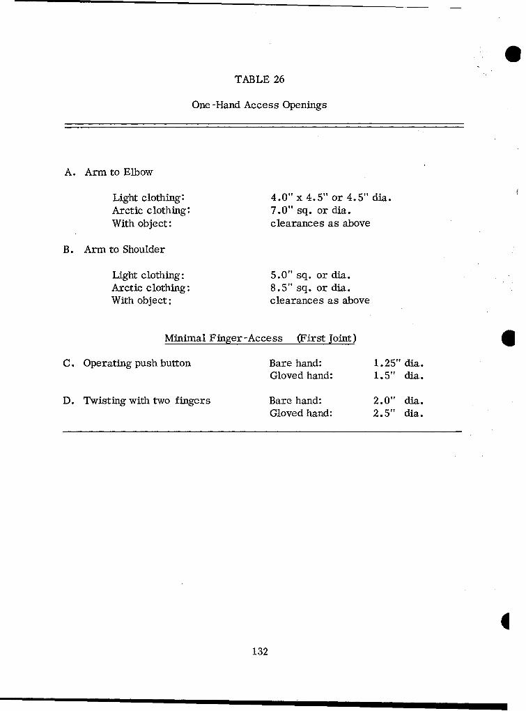
0TABLE 26
One-Hand Access Openings
A. Arm to Elbow
Light clothing: 4.0" x 4.5" or 4.5" dia.Arctic clothing: 7.0" sq. or dia.With object: clearances as above
B. Arm to Shoulder
Light clothing: 5.0" sq. or dia.Arctic clothing: 8.5" sq. or dia.With object: clearances as above
Minimal Finger-Access (First Joint)
C. Operating push button Bare hand: 1.25" dia.Gloved hand: 1.5" dia.
D. Twisting with two fingers Bare hand: 2.0" dia.Gloved hand: 2.5" dia.
1132
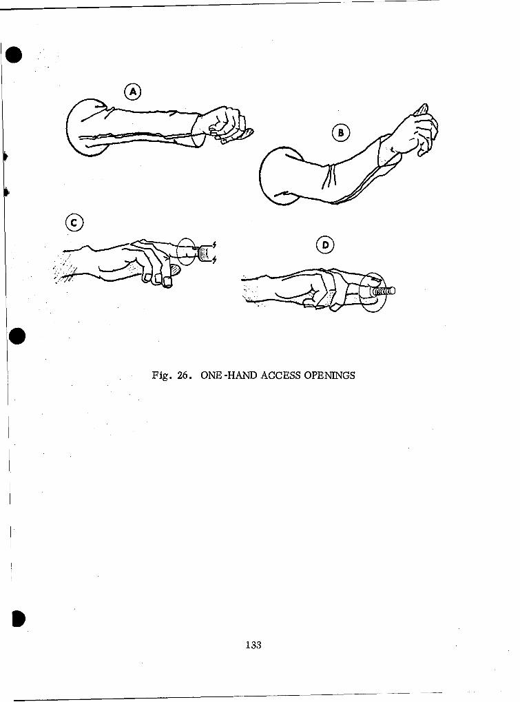
O 0
Fig. 26. ONE-HAND ACCESS OPENINGS
133
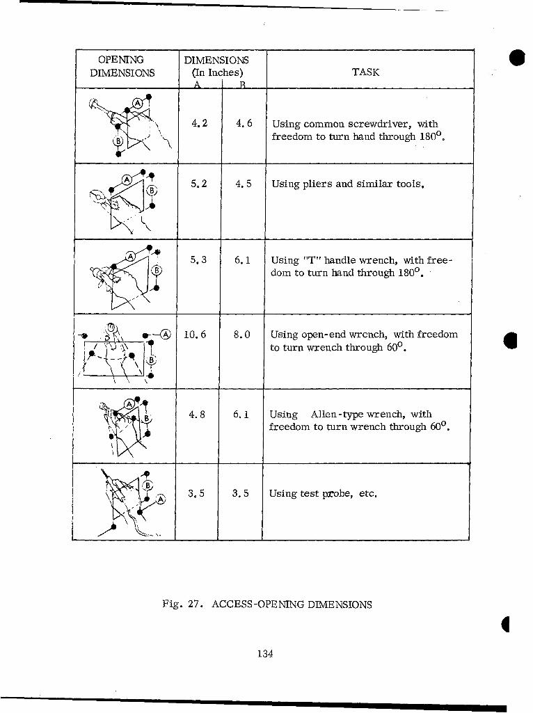
OPENING DIMENSIONS 0DIMENSIONS (In Inches) TASK
___A _
4.2 4.6 Using common screwdriver, with
freedom to turn hand through 1800.
"5.2 4. 5 Using pliers and similar tools.
A 5.3 6. 1 Using "T" handle wrench, with free-
dom to turn hand through 1800.
-1 - 10.6 8.0 Using open-end wrench, with freedomF_/ 77 ito turn wrench through 600.
- 4.8 6. 1 Using Allen-type wrench, withfreedom to turn wrench through 600.
3.5 3.5 Using test probe, etc.
Fig. 27. ACCESS-OPENING DIMENSIONS
134
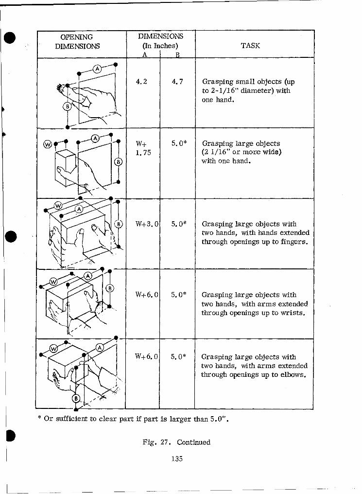
OPENING DIMENSIONSDIMENSIONS (In Inches) TASK
A __B
A
4.2 4.7 Grasping small objects (upto 2-1/16" diameter) with
one hand.
SR --A W+ 5. 0* Grasping large objects1.75 (2 1/16" or more wide)
"with one hand.
B' W+3. 0 5. Q* Grasping large objects withtwo hands, with hands extended
. K through openings up to fingers.
OB W+6. 0 5. 0* Grasping large objects withtwo hands, with arms extended
through openings up to wrists.
A
W+6. 0 5. 0* Grasping large objects withtwo hands, width arms extendedthrough openings up to elbows.
A-
B -
* Or sufficient to clear part if part is larger than 5.0".
Fig. 27. Continued
135
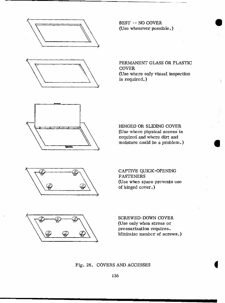
___________________BEST -- NO COVER
(Use whenever possible.)
PERMANENT GLASS OR PLASTICCOVER(Use where only visual inspectionis required.)
HINGED OR SLIDING COVER(Use where physical access isrequired and where dirt andmoisture could be a problem.)
CAPTIVE QUICK-OPENINGFASTENERS(Use when space prevents useof hinged cover.)
_ _ __ SCREWED-DOWN COVER(Use only when stress orpressurization requires.Minimize number of screws.)
Fig. 28. COVERS AND ACCESSES
136
Location of Accesses
Accesses should be located:
a. Only on equipment faces that are accessible as normally installed.
b. For direct access and maximum convenience for job procedures.
c. On the same face of the equipment as related displays, controls, testpoints, cables, etc.
d. Away from high voltages or dangerous moving parts (if not, provideadequate insulation, shielding, etc., around such parts so personnel will not beinjured).
e. So that heavy items can be pulled out, rather than lifted out.
137
CONNECTORS
1. Connectors should be compatible with:
a. Lines and Cables (page 161).
b. Fasteners (page 151).
c. Mounting (page 166).
d. Environmental extremes they will be subjected to.
e. Maintenance routines they are involved in.
2. Connectors should be selected, designed, and mounted for:
a. Fast, easy maintenance operations.
b. Easy removal and replacement of components and units.
c. Fastest time to set up test and service equipment.
d. Minimum danger to personnel and equipment from pressures, contents,or voltages of lines during the release of connectors.
e. Hand operation where possible, or use with common hand tools.
3. Standardize connectors to minimize errors like mismating and crossconnection during installation or maintenance.
4. Use connectors that are clearly different and physically incompatible whenlines differ in content (i.e., different voltages, oils, gases, etc.).
5. Connectors should be accessible:
a. With a minimum of disassembly or removal of other equipment or items.
b. In proportion to how often they are operated; connectors used during pre-operating checks should be the most accessible.
6. Connectors should be located so that:
a. Personnel can reach them easily to connect or disconnect them.
b. They are visible enough that personnel can mate threads or pins withoutdamaging them.
138

c. Fluids will not spill or leak -- but, even if they do, will not damageequipment.
d. There is enough space around each connector to grasp it firmly whenconnecting and disconnecting it.
7. In general, connectors should be separated at least:
a. 0.75" if used with bare fingers.
b. 1.25" if used with both bare and gloved fingers.
c. 3.00" if used with gloved or mittened hand.
d. As required for tool clearances.
8. Connectors should be designed and located so pressures, contents, orvoltages of lines will not endanger personnel or equipment when connectors arereleased or handled.
9. Design and locate connectors so they will not be damaged by:
a. Movements of personnel, shifting objects, opening doors, etc.
b. Excessive tightening or man-handling during operation.
c. Shorts, or arcing from foreign objects, erroneous connection, orhandling after disconnection.
10. Protect connectors by:
a. Recessing receptacles as necessary.
b. Recessing delicate parts (pins, keys, etc.) within the connector so theyare not exposed to harmful contact.
c. Providing protective caps, inserts, covers, cases, and shields asnecessary.
11. Connectors should be selected, designed, and installed so they cannot bemismated or cross-connected. The following means should be considered:
a. Use different sizes or types of connectors.
b. Arrange cables so their lengths correspond to the distances from theconnector to the correct point of attachment.
139

c. Arrange wires, or provide separation blocks or other mounts, so thesequence of leads is obvious.
d. Polarize connectors or use different sizes of prongs and prong receptaclesso lines with different voltages cannot be mismatched.
e. Use different -- and mutually incompatible and irreversible -- arrange-ments of guide pins, keys, or prongs.
f. Color-code or label connectors and receptacles so mismating is unlikely.
12. Connectors and associated parts and wiring should be coded and identified to:
a. Key them to references in the job instructions.
b. Identify replaceable items and parts for reordering.
c. Expedite and facilitate maintenance and trouble -shooting procedures.
d. Indicate the sequence routine or test procedures.
e. Provide adequate warnings or cautions about using connectors.
13. Label or code connectors and receptacles, as necessary, to ensure that:
a. Each plug is clearly identified with its receptacle.
b. Each wire is clearly identified with its terminal post or pin.
c. Test points are clearly identified by a unique mark or symbol.
d. Non-interchangeable connectors are clearly distinguishable.
e. The manner of connection or disconnection is obvious.
f. Plugs and receptacles have painted strips, arrows, or other indicationsto show how pins should be aligned for proper insertion.
g. Terminal strips and circuit boards are marked permanently to identifyindividual terminals and facilitate replacing them.
h. Power receptacles for primary, secondary, or utility systems are clearlylabeled to prevent personnel injury or equipment damage.
1140
14. Labels or codes on connectors and associated items should be located so that:
a. They are maximally visible during maintenance.
b, They are visible whether the connector is connected or disconnected. Itshould be possible to identify connectors without disconnecting them.
c. Their position is consistent in relation to associated pins, terminals,receptacles, etc.
15. The location for labels or codes are, in order of preference:
a. First - - Directly on the connector and receptacle.
b. Second -- On plates permanently attached to the connector and receptacle.
c. Third -- On tabs or tapes attached to the connector.
-- For receptacles, on the surface or panel immediately adjacentto the receptacle.
-- For recessed receptacles, on or near the access opening.
Classification of Connectors (in order of preference)
1. Plug-in connectors are the fastest and easiest to use, but they have lowholding power; therefore:
a. Do not use plug-in connectors when accidental pulls on the cable maydisconnect them.
b. Use plug-in connectors for cables that are connected and disconnectedfrequently.
2. Quick -disconnect devices have a variety of forms, including any type ofconnector that can be released by snap action, twisting up to a full turn, triggeringa latch or spring device, or removing an external pin.
3. Use quick-disconnect devices to connect:
a. Items which must be disconnected or replaced frequently.
b. Items which must be replaced within critical readiness times.
141
4. Threaded connectors provide very secure connections, particularly whenlocked into place by set screws, retainers, or safety wires. They usually take longerto operate, depending on the number of turns and the types of tools they require.
5. Threaded connectors should:
a. Use the fewest turns that will satisfy holding requirements.
b. Operate by hand, if used for electrical connections.
c. Require only common hand tools.
d. Minimize the danger of accidentally loosening other connectors whileworking on one.
Electrical Connectors
1. Electrical connectors should have low insertion forces to minimize thepossibility of damaging contact surfaces.
2. Electrical plugs should be designed, installed, and mounted so that:
a. It is impossible to insert the wrong plug into a receptacle.
b. It is impossible to insert a plug in its own receptacle the wrong way.
c. Wherever possible, plugs have multiple contacts, to reduce the numberof plugs and, consequently, the number of maintenance operations.
d. Connectors "plug-in" or secure with no more than one complete turn,especially with auxiliary or test equipment.
e. Wiring is routed through the plugs and receptacles so disconnection doesnot expose "hot" leads.
f. All "hot" contacts are socket contacts or female connectors (i.e., recep-
tacles are "hot" and plugs are "cold" when disconnected).
g. Plugs are self-locking or use safety catches, rather than requiring safetywiring.
1142
3. Alignment keys or pins should be designed and located within the plug so that:
a. They extend beyond electrical pins to protect the pins from damage if theconnector is misaligned.
b. They are arranged asymmetrically to prevent incorrect plug insertions.
c. All alignment pins for a given plug or series of plugs are oriented in thesame direction. If this conflicts with precautions against mismating, pin orientationsshould differ consistently and systematically, for the technician's convenience.
4. Test points should be:
a. In plugs when test points are required but have not been provided elsewhere
b. In adapters to be inserted between the plug and receptacle, if test pointscannot be incorporated into the plug and no other test points are available.
c. Accessible, with adequate working clearances, when the plug or adapteris in its normal position.
d. Coded and labeled so they can be seen clearly and identified easily in* test procedures.
Fluid and Gas Connectors
1. Connectors for pipes, tubing, hoses, etc., should be located andinstalled so that:
a. It is not necessary to jack the equipment up to drain it, fill it, orperform other maintenance involving the connectors.
b. The technician can perform leakage tests easily and without danger.Tests should be planned so the technician does not have to hold his head in areas ofextreme noise, vibration, or other danger while the equipment is running.
2. Gaskets and seals should be selected and installed so that they can bereplaced easily without removing other connector parts or disassembling otherequipment.
3. There should be job instructions giving the expected life of seals andgaskets and recommending when they should be changed.
4. Part of a gasket or seal should be visible after it is installed, as a checkW on failure to replace seals after disassembly.
143
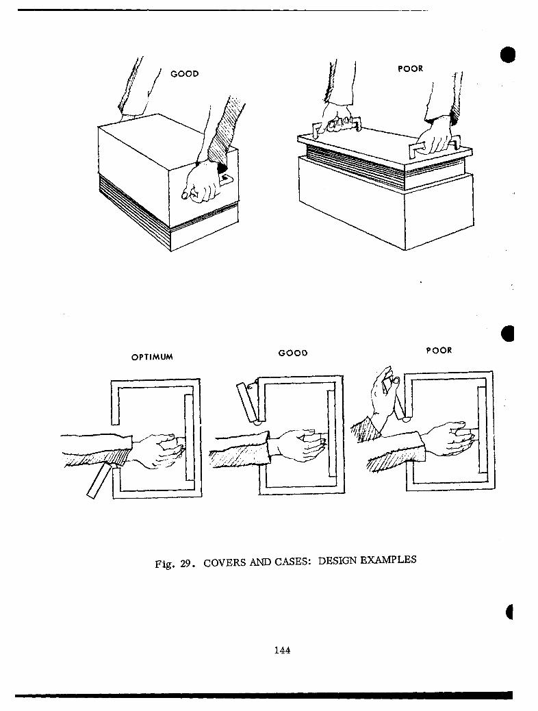
GOOD /POORS
J II
OPTIMUM GOOD POOR
Fig. 29. COVERS AND CASES: DESIGN EXAMPLES
1
144t

O COVERS AND CASES
1. Covers, cases, and shields should be provided as necessary to:
a. Divide enclosures into sections which are cleaned by different methods.
b. Keep personnel from touching dangerous electrical or mechanical parts.
c. Protect delicate or sensitive equipment so it will not be damaged bymovements of personnel, shifting cargo, loose objects, or installing and maintainingnearby assemblies.
2. Covers, cases, and shields should also be designed for fast, easy mainte-
nance (Fig. 29). Their maintenance characteristics depend largely on:
a. How they are fastened.
b. Size, weight, and ease of handling.
c. Handles or provisions for tool grips.
d. Work space and clearance around them.
e. How often they must be opened or removed (i.e., the reliability andmaintainability of the components they enclose).
3. A cover, case, or shield should have these characteristics:
a. Lightweight if possible, but whatever size is necessary for the degree ofenclosure and the accessibility required.
b. Openable, removable, and transportable by one hand, by one man, orby two men (in that order of preference).
c. Handles or tool grips provided if it is heavy, difficult to open, ordifficult to handle.
d. Enough clearance around enclosed components to prevent damage andavoid requiring extremely fine or careful positioning and handling.
e. Designed and located so bulkheads, brackets, or other units do notinterfere with using it, and so it will not interfere with other maintenance operationswhen it is open.
145
4. The shape of the cover, case, or shield should be chosen as follows:
a. Use any shape appropriate for the degree of enclosure, accessibility,and the clearances required.
b. Make it obvious how the item must be positioned or mounted.
c. Make it obvious how enclosed delicate components are oriented, toprevent damage during removal.
d. Avoid indentations or settling areas on top surfaces, to prevent rustand corrosion, and keep dirt and grease from accumulating.
5. Covers, cases, and shields should be designed, located, and mounted so that:
a. They can be completely removed and replaced if they are damaged.
b. Irregular extensions and accessories can be removed readily.
c. They can be opened or removed as necessary, without taking the equip-ment apart or removing auxiliary equipment.
d. They have props, retainers, or other support where required so theequipment will not be unbalanced when opened.
e. When open, they do not obscure or interfere with controls, displays,test points, or connections used in working inside the access or enclosure.
f. They have adequate stops and retainers to keep them from swingingagainst or being dropped on fragile equipment or on personnel.
g. They have locking devices or retaining bars to hold them open if theymight otherwise fall shut and cause damage, injury, or inconvenience. This isparticularly necessary for doors, covers, and shields which may be used in highwinds.
1146
6. Fasteners for covers, cases, and shields should be selected, applied, andmounted so that:
a. They satisfy the preferences, requirements, and standardization aspectsunder "Fasteners" (page 151).
b. Hinges, latches, and catches are used wherever possible to reducehandling and stowirg of covers and cases.
c. It is obvious when a cover or case is not in place or is not securelyfastened. Where possible, spring-load fasteners so they stand out or the cover itselfstays ajar when it is not secure.
7. Labels and markings on covers and cases should:
a. Tell how to open, remove, and position them, unless the design itselfmakes operation obvious.
b. Clearly indicate the functions of units behind the enclosure or thefunctions which are performed through the access (such as "Battery, " "Fuel Pump,""Oil Here," etc.).
c. Warn about any dangers or hazards involved in removing the cover orW case, or working within the enclosure.
d. Indicate how units, service equipment, etc., should be oriented orconnected to go through the opening (unless this is already obvious).
e. Present instructions so they will be visible and properly oriented to amaintenance technician when the cover, door, or case is open.
8. Cases should be selected, designed, and mounted so that:
a. Cases lift off of units, rather than units lifting out of cases -- particularlywhen subassemblies are heavy (Fig. 29).
b. They are somewhat larger than the items they cover, so items insidecan be removed and replaced easily without damaging wires or other components.
c. They have guidepins and tracks as necessary to help align the case,prevent it from cocking or binding, and to protect delicate or sensitive componentsfrom damage when the case is moved.
d. There is access to frequently used adjustment, test, or service points,so the case need not be removed for routine maintenance.
147
e. All aspects and portions of the equipment that are significant for mainte-nance are fully exposed when the case is removed.
f. Rubber stripping or other sealing material is selected and mounted sopersonnel will not damage it when the case is moved.
9. Covers are listed below in order of preference, and should have the followingcharacteristics:
a. Hinged doors, hoods, and caps allow fastest and easiest access, withrelatively few fasteners, and the cover is supported so the technician does not have tohandle it. However, these covers do require "swinging space," which may interferewith other operations or components. When using hinged covers, consider the following:
(1) Where "swinging" or opening space is limited, use double-hingedor split doors.
(2) Place hinges at the bottom of the door, or provide a prop, catch, orlatch to hold the door open - - particularly if the door must be opened in high winds(Fig. 29).
(3) When hinged doors are adjacent, they should open in opposite direc-tions to maximize accessibility.
(4) Design hinged caps over service or test points so they will notinterfere with inserting or attaching service or test equipment.
(5) Use stops, retainers, etc., as necessary to keep doors from swing-ing into adjacent controls or fragile components, and so they will not spring theirhinges.
b. Sliding doors or caps are particularly useful where "swinging space" islimited. Small sliding caps are useful for small accesses that do not require a tightseal. When sliding covers are used, the following should be considered:
(1) Sliding doors and caps should lock positively.
(2) They should be designed so they will not jam or stick.
(3) They should be easy to use, and personnel should be able to usethem without tools.
(4) Opening or closing them should not interfere with, damage, or makepotentially harmful contact with wires or other equipment items.
1148
c. Removable doors, plates, or caps require little space for opening and,once removed, do not interfere with work space. However, handling them takes timeand effort, e.g., searching, bending, reaching, etc. When using removable covers,consider the following:
(1) Use tongue-and-slot or similar catches wherever possible for smallplates, doors, and caps, to minimize the number of fasteners required.
(2) If small plates and caps are likely to be misplaced or damaged,secure them with retainer chains (see "Fasteners," page 151).
(3) If a removable plate must be attached in a certain way, design it soit cannot be attached improperly (i.e., use an asymmetric shape, locate mountingholes asymmetrically, or code both plate and structure with labels that will align whenthe plate is properly installed).
d. Removable panels or sections give access to whole sides of equipment.They discourage non-maintenance personnel from opening the access. They do notrequire "swinging space," but they are easily damaged and awkward to handle. Theymay also interfere with maintenance. When they are used, the following should beconsidered:
(1) Panels that must be removed for maintenance should be held with aminimum of combination-head, captive fasteners. Spring-loaded, quarter-turnfasteners are particularly recommended.
(2) It should be apparent when fasteners have been released.
(3) Panels and sections should be designed so one man can carry themand install or remove them with common hand tools.
(4) Panels and sections should have handles to facilitate removal,handling, and replacement.
(5) It should not be necessary to disconnect wires, components, etc.,from a panel before removing it. If such items are attached to the panel, the panelshould be hinged so they need not be removed.
I1149
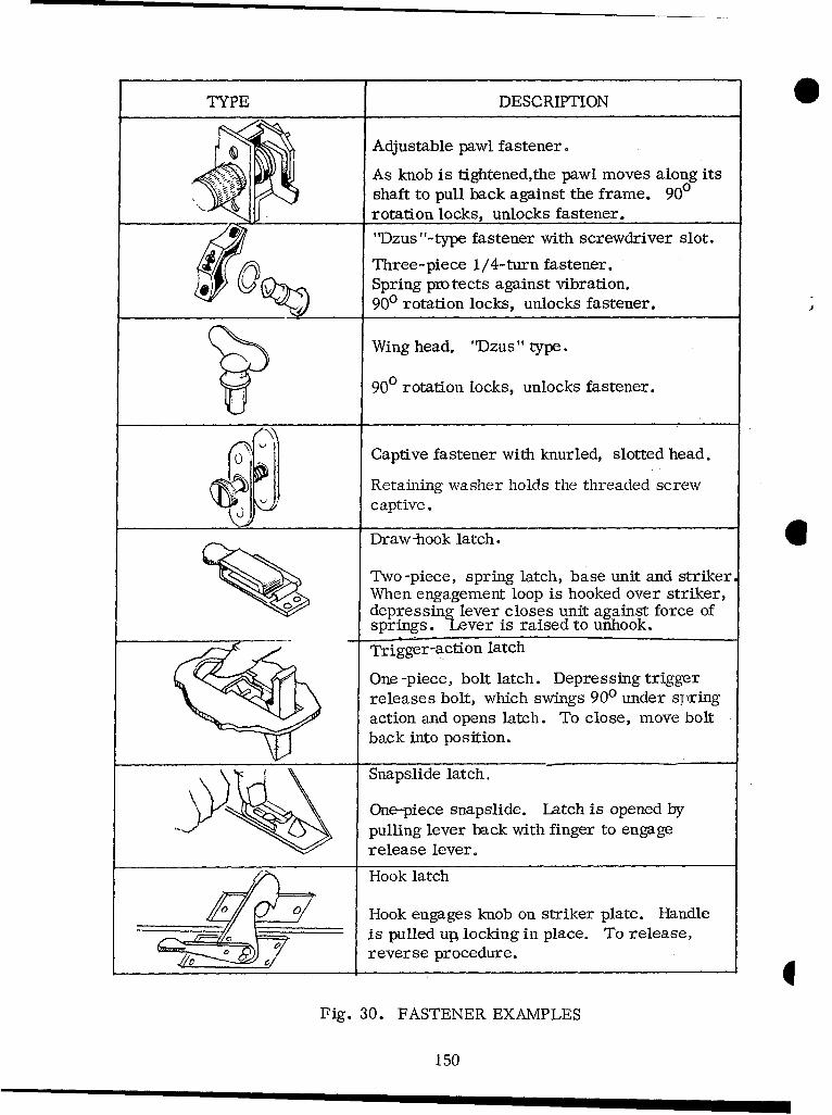
TYPE DESCRIPTION
Adjustable pawl fastener.
As knob is tightened,the pawl moves along itsshaft to pull back against the frame. 900rotation locks, unlocks fastener.
"Dzus "-type fastener with screwdriver slot.
Three-piece 1/4-turn fastener.Spring pro tects against vibration.900 rotation locks, unlocks fastener.
Wing head. "Dzus " type.
90 rotation locks, unlocks fastener.
Captive fastener with knurled, slotted head.
Retaining washer holds the threaded screw0• captive.
Draw-hook latch.
Two-piece, spring latch, base unit and striker.When engagement loop is hooked over striker,depressing lever closes unit against force ofsprings. Lever is raised to unhook.
Trigger-action latch
One-piece, bolt latch. Depressing triggerreleases bolt, which swings 900 under springaction and opens latch. To close, move boltback into position.
Snapslide latch.
One-piece snapslide. Latch is opened by"pulling lever back with finger to engagerelease lever.
Hook latchHook engages knob on striker plate. Handle
is pulled up locking in place. To release,reverse procedure.
Fig. 30. FASTENER EXAMPLES
150
. FASTENERS
1. The desigh, selection, or application of fasteners should consider thefollowing factors:
a. Work space, tool clearance, and wrenching space needed around thefastener.
b. Types of tools required to operate the fastener, depending on type offastener, application, and location.
c. Frequency of use.
d. Time available for tasks involving operation of the fasteners.
2. Fasteners are available in a wide variety of types and sizes, and new typesare always appearing. Before selecting fasteners, review the varieties available.Fasteners should be selected for durability, easy operation, speed, easy replacement,and other criteria in this section.
3. Standardize fasteners wherever possible to reduce spare parts and minimize* the danger that personnel will damage them by using the wrong tool or fastener for a
given application.
4. Minimize the number of types and sizes of fasteners within the system by:
a. Using only a few basic types and sizes which are readily distinguishablefrom each other (see Fig. 30 for representative examples).
b. Using the same type and size of fastener consistently for a given applica-tion (e.g., all mounting bolts should be the same for a given type of item).
c. Making certain that screws, bolts, and nuts with different threads alsohave clearly different physical sizes, so they will not be interchanged.
5. Minimize the types and sizes of tools required for fastener operation by:
a. Avoiding fasteners that require special tools.
b. Selecting fasteners that can be operated by hand or by common hand tools.
6. In designing, consider how stripped, worn, or damaged fasteners can bereplaced. Avoid fasteners (studs) which are an integral part of the housing.
I151
7. Fastener mounting holes or other tolerances should be large enough to allow *"starting" fasteners without perfect alignment.
8. Attach hinges, catches, latches, locks, and other quick-disconnect deviceswith small bolts or screws, not with rivets.
9. Mount nuts and bolts, particularly those which are operated frequently orwhich are not very accessible, so they can be operated with one hand or one tool:
a. Provide recesses to hold either the nut or the bolt.
b. Attach either the nut or the bolt semi-permanently.
c. Use double nuts on terminal boards and similar applications.
d. Use nut plates, gang-channeling, or floating nuts.
10. Use a few large fasteners rather than many small ones (unless systemrequirements dictate otherwise).
11. Fasteners should be located so that they:
a. Can be operated without removing other parts or units first.
b. Can be operated with minimum interference from other structures.
c. Do not interfere with each other or with other components during release.
d. Are not hazards to personnel, wires, or hoses.
e. Have adequate hand or tool clearance for easy operation. Consider thatit may take two hands or power tools to manipulate, breakaway, or remove stuckfasteners.
12. Fasteners that are normally operated by hand should be durable enough thatthey can be turned with a wrench.
152
* Types of Fasteners (in order of preference)
1. Quick connect-disconnect devices -- Fast and easy to use, do not requiretools, may be operated with one hand, and are very good for securing plug-in compo-nents, small components, and covers. However, their holding power is low, andthey cannot be used where a smooth surface is required.
2. The following factors should be considered in selecting quick connect-disconnect fasteners:
a. Use these fasteners wherever possible when components must bedismantled or removed frequently.
b. These fasteners must fasten and release easily, without requiring tools.
c. They should fasten or unfasten with a single motion of the hand.
d. It should be obvious when they are not correctly engaged.
e. When there are many of these fasteners, prevent misconnections bygiving the female section a color or shape code, location, shape, or size so it willbe attached only to the correct male section.
3. Latches and catches -- Very fast and easy to use, do not require tools, havegood holding power; especially good for large units, panels, covers, and cases. Theycannot be used where a smooth surface is required.
4. The following factors should be considered in selecting latches and catches:
a. Use long-latch catches to minimize inadvertent releasing of the latch.
b. Spring-load catches so they lock on contact, rather than requiringpositive locking.
c. If the latch has a handle, locate the latch release on or near the handleso it can be operated with one hand.
5. Captive fasteners -- Slower and more difficult to use, depending upon type,and usually require using common hand tools; but they stay in place, saving time thatwould otherwise be wasted handling and looking for bolts and screws; can be operatedwith one hand.
6. The following factors should be considered in the selection of captivefasteners:
a. Use captive fasteners when "lost" screws, bolts, or nuts might cause a
malfunction or excessive maintenance time.
153

b. Use fasteners which can be operated by hand or with a common hand tool.
c. Use fasteners which can be replaced easily if they are damaged.
d. Captive fasteners of the quarter-turn type should be self-locking andspring-loaded.
7. Regular screws -- Round, square, or flat-head screws take longer to useand are more subject to loss, damage, stripping, and misapplication.
8. Square-head screws are generally preferable to round or flat ones; theyprovide better tool contact, have sturdier slots, and can be removed with wrenches.
9. The following factors should be considered in the selection of screws:
a. Screw heads should have deep slots that will resist damage.
b. Use screws only when personnel can use screwdrivers in a "straight-in"fashion; do not require personnel to use offset screwdrivers.
10. If personnel must drive screws blindly, provide a guide in the assembly tohelp keep the screwdriver positioned properly.
11. Bolts and nuts -- Bolts are usually slow and difficult to use. Personnel musthave access to both ends of the bolt, use both hands and, often, use two tools. Also,starting nuts requires precise movements. There are many loose parts to handle andlose (nuts, washers, etc.).
12. Keep bolts as short as possible, so they will not snag personnel or equipment.
13. Coarse threads are preferable to fine threads for low torques.
14. Avoid left-hand threads unless system requirements demand them; thenidentify both bolts and nuts clearly by marking, shape, or color.
15. Use wing nuts (preferably) or knurled nuts for low-torque applications,because they do not require tools.
16. Combination-head bolts and screws -- Preferable to other screws or bolts,because they can be operated with either a wrench or a screwdriver, whichever ismore convenient, and there is less danger of damaged slots and stuck fasteners. Ingeneral, slotted hexagon heads are preferable to slotted knurled heads.
17. Internal -wrenching screws and bolts - - Allow higher torque, better tool grip,and less wrenching space. But they require special tools, are easily damaged, andare difficult to remove if damaged. They also become filled with ice and frozen mud.
154
18. The following factors should be considered in selecting internal-wrenchingfasteners:
a. Minimize the number of different sizes to minimize the number of specialtools; preferably, use only one size.
b. Select fasteners with deep slots, to reduce the danger of damaged fasteners.
c. Design so there will be a way to remove damaged internal-wrenchingfasteners.
19. Rivets -- These permanent fasteners are very hard and time-consuming to
remove. They should not be used on any part which may require removal.
20. Cotter key use should consider the following:
a. Keys and pins should fit snugly, but they should not have to be driven inor out.
b. Cotter keys should have large heads, for easy removal.
21. Safety wire use should consider the following:
a. Use safety wire only where self-locking fasteners or cotter pins cannotwithstand the expected vibration or stress.
b. Attach safety wire so it is easy to remove and replace.
22. Retainer ring use should consider the following:
a. Avoid rings which become difficult to remove and replace when they areworn.
b. Use rings which hold with a positive snap action when possible.
23. Retainer chains should be used to:
a. Keep hatches or doors from opening too far and springing their hinges.
b. Turn doors or covers into useful shelves for the technician.
c. Prevent small covers, plates, or caps from being misplaced.
d. Secure small, special tools where they will be used.
155

e. Secure objects which might otherwise fall and injure personnel.
24. The selection of retainer chains for use in design should consider thefollowing:
a. Use link, sash, or woven-mesh chains. Avoid bead-link chain, becauseit breaks more easily than other types.
b. Attach chains with screws or bolts; attach them strongly and positively,but so they can be disconnected easily when required.
c. Provide eyelets at both ends of the chain for attaching to the fasteners.
d. Chains should not be longer than their function requires.
1
156
. HANDLES
1. The dimensions (Fig. 31), location, and position of a handle depend on:
a. Weight of the item or unit.
b. Number of men, or hands, required to lift or carry it.
c. Type of clothing and gloves users wear.
d. Itemis operational position relative to other items and obstructions.
e. How the item is handled or positioned.
f. How far the item must be carried.
g. How often the item must be handled or carried.
h. Additional uses for the handle.
2. Handles should be designed and located to:
0 a. Guard against operating controls accidentally.
b. Protect delicate parts of instrument faces.
c. Serve as locking devices to secure components in place.
d. Serve as protective supports or stands (e.g., so they can be used asmaintenance stands when items are inverted).
* 3. Use hand-shaped handles when items must be carried frequently or for longperiods, to prevent undue side pressure on the fingers.
4C Recessed, concealed, or folding handles may be used to conserve space,but they must be accessible without tools and must remain securely folded when notin use.
5. Handles should be located so that:
a. If there is only one handle, it is over the center of gravity.
b. If there are two or four handles, they are equidistant from the center ofgravity.
1157
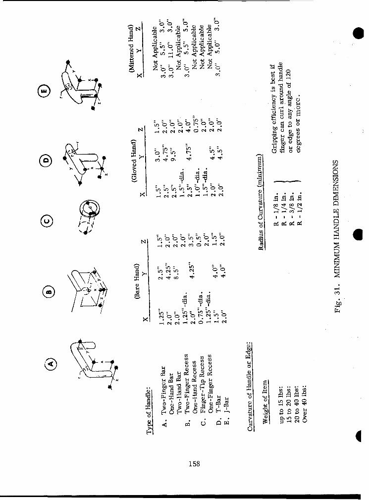
0 u 00
'-O -- ' '-r
0 4.
0 -7
0 0
0)0
7 4-1-4
Or-if r-
. . . .E -. zj~W
r- Lr - mL
z
4-T
0)0
"I C I I ýC
""1 00x ý4 -4
0d co
NU
MI158CýC'
c. Their locations do not interfere with operating or maintaining the equipment.
d. There is at least 2.5 inches of clearance between handles and obstructions.
e. They are on the front of a panel if it must be pulled from a rack.
f. They can be held comfortably.
g. The item which is carried will ride clear of the legs of personnel.
6. Handles, lugs, and other handling gear (casters, push bars, etc.) should bepermanent parts of the equipment case.
7. Hoist lugs (lifting-eyes) should be provided on all equipment weighing morethan 150 pounds. Mark "LIFT HERE" adjacent to each lug, and allow at least fourinches space around the lifting eyes, for convenient use.
159
HANDLING EQUIPMENT
Jacks
1. Jacks should be designed so they can be transported, handled, and storedeasily. Small jacks that one man must lift and carry should not weigh more than40 pounds.
2. Jack handles should be designed so they can be removed or folded when thejack is not in use.
3. Jacks should be labeled to indicate:
a. The direction to turn the jack handle for raising and lowering.
b. The load they are designed to carry.
4. On hydraulic jacks, there should be mechanical safety-locking devices tokeep the load from falling if the hydraulic system fails.
Cranes 61. Sections of crane booms should have hook eyes at their center of gravity for
easier assembly and disassembly.
2. Where feasible, the boom length should be adjustable to make the equipmentmore versatile.
3. The crane operator's station should be located where he will have the bestview of the load, the ground, and other equipment in the vicinity.
4. The main boom angle -indicator display should be easily visible to theoperator and coded to alert the operator when there is danger of exceeding the maxi-mum load angle.
5. Boom controls should have labels indicating their functions and direction ofmotion.
6. Boom controls should be spring loaded so they return to the stop positionwhen released.
7. Crane hooks should have handles so operators can hold or guide hooks duringlifting, without danger of injury. 4
160
8. The mouths of crane hooks should have safety-closure locking devices thatare easy to open or close.
9. Retainers or locks used to keep booms in place during transport should beidentified clearly and unambiguously.
LINES AND CABLES
1. Lines and cables should be selected, designed, bound, routed, and installedso the following operations can be performed quickly:
a. Troubleshooting, testing, checking, and isolating malfunctions.
b. Tracing, removal, repair, and replacement.
c. Removing and replacing other items and components.
0 d. Connecting and disconnecting.
2. Lines and cables should be compatible with:
a. Connectors (page 138).
b. Fasteners (page 151).
c. Accesses (page 130).
d. Environmental extremes they will be subjected to.
3. Lines and cables should be routed and mounted so that:
a. They are accessible without disassembling or removing other equipment.
b. Points of connection, mounting, splicing, or testing should be especiallyaccessible.
c. They can be removed and replaced completely if they are damaged.
d. There are accesses and clearances for removing and replacing them.
161
4. Lines and cables should be routed so personnel will not use them for hand-holds or footrests.
5. Lines and cables should be routed and mounted so moving or rotating partswill not snag them, and so they do not interfere with normal operation.
6. Clamps or plates that mount lines and cables:
a. Should be spaced not more than 24 inches apart so personnel canremove one with each hand.
b. Should have heat-insulating liners so they do not become hot enoughthat personnel could be burned.
c. Should be designed so personnel can install or remove them with onehand, with or without common hand tools.
d. If cables are removed frequently, should be of a quick-release, hinged,or spring type. Hinged clamps are preferable, because they support the weight of theline during maintenance, freeing the technician's hands for other tasks. For overheadmounting, use a spring clamp with a hinged-locking latch over the clamp's open sideto prevent accidents.
7. There should be adequate provision for handling and storing extension cables 0and cables used with ground power, service, and test equipment.
a. Provide adequate, covered space for storing lines and cables in supportequipment.
b. Provide suitable racks, hooks, or cable winders in the storage space tohold lines and cables conveniently accessible.
c. Provide reels or reel carts for handling large, heavy, or very long linesand cables. Use automatic or power tensioning or rewinding reels where possible tomake handling easier.
d. Use wheeled or mobile supports for extra-large lines and cables thatmust be moved frequently.
8. Install cables so foreign objects, flying stones, etc., will not damage them.
1162
O Fluid and Gas Lines
1. To avoid the possibility of mismating connectors during servicing or mainte-nance:
a. Standardize fittings so lines that differ in content cannot be interchanged.
b. Code lines by arrangement, size, shape, and color as necessary.
c. Use colored bands to identify all lines that carry fluids.
*2. Keep lines from spraying or draining fluid on personnel or equipment whenthey are disconnected by:
a. Locating connections away from work areas and sensitive components.
b. Shielding sensitive components where required.
c. Providing drains and bleed fittings so lines can be drained or depressurizedbefore they are disconnected.
d. Providing highly visible warning signs at connectors or wherever pressuresor the contents of lines could injure personnel.
3. Prevent drainage problems by:
a. Designing lines so they can be emptied completely when necessary.
b. Making bends horizontal, rather than vertical, to avoid fluid traps.
c. Avoiding low points or dips in lines that make them difficult to drain.
d. Providing special drains at low points where necessary.
4. Mount and install lines so that:
a. Rigid lines with fittings do not have to be backed-off before they can bedisconnected.
b. Use flexible tubing, rather than rigid lines, where feasible -- it allowseasier handling, can be backed-off easily, and is easier to thread through equipmentwhen it must be replaced.
c. Use flexible hose, rather than pipes or tubing, when there is only limitedspace for removing, replacing, or handling lines. It can be backed-off or pushedaside for access to other components.
163
5. Provide adequate supports for lines from external service or test equipment,or where extensions will be attached for other purposes. These supports must with-stand not only the initial pressure through the line and the weight of its externalextensions, but the rigors of handling and repeated connection and disconnection aswell.
Electrical Wires and Cables
1. Make the layout and routing of wires as simple and logical as possible by:
a. Combining wires into cables (preferable) or into harnesses.
b. Minimizing the number of wires, harnesses, and cables.
c. Grouping conductors into cables - - and within cables or harnesses -- bytheir functions and relationships to replaceable items.
2. Conductors should be coded and labeled:
a. As provided under "Connector Requirements," (page 138).
b. So each conductor can be identified throughout the length of each cable orharness, wherever tracing is required.
c. So codes and labels correspond to connector designations, test pointdesignations, and connector functions.
3. Mount electrical wires, harnesses, and cables so there is adequate accessi-bility through raceways, conduits, junction boxes, etc.
4. Route electrical wires and cables over, rather than under, pipes or fluidcontainers.
5. Wire and cable routes should be away from or suspended over areas wherefluids may drip or accumulate (e.g., pans and trenches, under floorboards, etc.).
6. Leads should not be longer than necessary, but their lengths should allow:
a. Easy connection and disconnection, with enough slack to back wiresaway from attachment points so units can be removed easily.
b. Enough slack so terminal fittings can be replaced at least twice andpreferably three times (if electrical considerations permit). 4
164
c. Moving units which are difficult to handle when mounted, to a moreconvenient position for connection or disconnection.
7. Mount leads so they are:
a. Separated far enough to clear the technician's hand or any tool requiredfor checking or connecting them.
b. Oriented, where possible, so they will not be connected incorrectly or"crossed."
8. Use extension cables to:
a. Increase efficiency and make maintenance easier.
b. Test assemblies or components without removing them.
c. Check each functioning unit in a convenient place.
d. Allow parking support equipment or setting it in a convenient place.
e. Serve as many related functions as possible, but avoid the possiblity ofOid misuse or misconnection.
165
MOUNTING AND ARRANGING
1. Most parts, items, and assemblies can be located in many places andarranged in many ways. For ease of maintenance and training, select arrangementsby these criteria:
a. Accessibility.
b. Standardization.
c. Reliability figures and factors (as indicators of access requirements.)
d. Operating stress, vibration, temperature, etc.
e. Requirements for built-in test and malfunction circuits or indicators.
f. The peculiar characteristics of each item or module, and particularly:
(1) Size, weight, and clearance.
(2) Fragility or sensitivity, which impose needs to protect it.
(3) Needs and procedures for servicing, adjusting, or repairing it. 0(4) Clearance for removing and replacing it.
(5) Access and clearance for tools around fasteners, connectors, test,or service points, etc.
(6) Specific factors such as critical lead length, weight balance, heatdissipation, etc., which may make it hard for personnel to carry out their tasks.
2. Arrange components, subassemblies and assemblies for easiest maintenanceby:
a. Minimizing requirements for technicians to move from place to placeduring servicing, checkout, or troubleshooting.
b. Minimizing the need for the technician to retrace his movements or stepsduring servicing, checkout, or troubleshooting.
c. Minimizing the number of inputs and outputs to components and items.
d. Arranging the equipment so the technician can either replace an individualitem of a group or replace the whole group, depending on the maintenance philosophy.
166
e. Equipping replacement components with new fasteners or brackets if theold ones are likely to be lost or damaged.
f. Avoiding making technicians follow long sequences of assembly stepsbefore they can maintain the equipment.
g. Using sliding racks, or hinged assemblies, for maximum accessibility.
h. Organizing equipment by maintenance specialties, so one specialist canmaintain his part of the system without removing or handling equipment that anotherspecialist maintains -- particularly when the equipment is critical or maintaining itrequires highly specialized skills.
3. Mount parts, subassemblies, assemblies, etc., so that:
a. They are accessible.
b. Fasteners are as recommended under "Fasteners," page 151.
4. Design mounting fixtures, brackets, etc., so:
a. Only interconnecting wires and structural members are permanently* attached to units; make all other fixtures removable for easy maintenance.
b. Fixtures attached to the chassis are either strong enough to last forthe life of the system or are replaceable.
c. Mounting is compatible with the part's size and weight, so leads will notfatigue and break, or the like, from the stress of normal handling.
5. Provide supports, guides, and guide pins as necessary to simplify handling,aligning, and positioning units.
6. Use shock mounts as necessary to:
a. Keep displays, markings, etc., from vibrating, not only to protectfragile or vibration-sensitive components and instruments, but also to prevent read-ing errors.
b. Isolate sources of high or dangerous noise and vibration, for moreeffective human performance.
7. Where personnel must mount parts without seeing them:
a. Secure the inaccessible side with mounts that allow exceptionally easymating.
167

b. Do not use friction lugs, tongue and groove fittings, etc.
8. Mount components, modules, and parts so they will not inadvertently bereversed, mismated, or misaligned during installation or replacement.
9. Components with the same form, function, and value should be completelyinterchangeable throughout the system; however, components with the same or similarform, but different functional properties, should be:
a. Mounted with the same orientation throughout the unit.
b. Readily identifiable, distinguishable from each other, and not physicallyinterchangeable.
10. Arrange and mount assemblies, components, parts, etc., so that:
a. There is adequate access around fasteners for tools and wrenches.
b. There is enough space to use test probes and other service or testequipment.
c. A given unit or component can be maintained:
(1) With the unit or component in place, if possible.
(2) Without having to disconnect, disassemble, or remove other itemsfirst.
d. All replaceable items, particularly disposable components, can be
removed:
(1) Without removing or disassembling other items or units.
(2) By opening a minimum number of covers, cases, panels, etc.
(3) Without hindrance from structural members or other parts.
(4) Along a straight or slightly curved line, rather than through anangle or a more devious course.
e. All heavy, large, or awkward units are located so they:
(1) May be slid out or pulled out, rather than lifted out.
(2) Do not block access to other removable items.
1168

a f. When one unit must be placed behind or under another, the unit requiringmorefrequent maintenance should be more accessible.
g. Structural members of items, chassis, or enclosures do not block accessto removable items, or to their connectors or fasteners.
h. Removing and replacing items require minimal tools and equipment, and,if practicable, only common hand tools.
i. Rapid, easy removal and replacement can be done by one man, by twomen, or by handling equipment (in that order of preference).
j. Irregular, fragile, or awkward extensions -- such as cables, hoses,etc. -- are easy to remove before the unit is handled; such protrusions make handlingdifficult, because they are so easy to damage.
k. Handling and carrying can be done efficiently by one man.
(1) Removable items should weigh less than 45 pounds.
(2) Items that are difficult to reach should weigh less than 25 pounds.
Sby two men. (3) Items weighing more than 45 pounds should be designed for handling
(4) Provide hoist lugs for assemblies weighing more than 90 pounds.
11. The design, arrangement, and mounting of components, units, parts, etc.,should give personnel maximum protection against injury.
12. Items should be located, arranged, mounted, and shielded so personnel canreach them, their fasteners, and adjacent items without danger from electricalpotentials, heat, sharp edges or points, moving parts, chemical contamination, orother hazards. Specifically:
a. Do not locate parts, fasteners, service, or test points, etc., that requirefrequent servicing, near exposed terminals or moving parts.
b. Provide guards or shields to keep personnel from touching dangerousmoving parts or electrical potentials.
c. Make ventilation holes small, and locate them where personnel cannotpoke fingers, tools, etc., into hazardous areas (e.g., 1/4" -diameter holes willexclude fingers).
169
d. Capacitors, exhaust pipes, and other parts which retain heat or electricalpotentials after the equipment is turned off should be located or shielded so personnel W
cannot touch them accidentally.
13. Mount adjustment and alignment devices where technicians cannot operatethem unintentionally.
14. Hold small removable pins, caps, covers, etc., captive with chains or thelike so they will not be lost or damaged.
15. Protect vital, fragile, sensitive, or easily damaged components by locating,arranging, and shielding them so they will not be:
a. Used for handholds, footholds, or rests.
b. Damaged by flying particles, loose objects, or movements of personnelor tools during maintenance.
1
170

O .TEST AND SERVICE POINTS
1. This section recommends ways to simplify testing and servicing.
2. Use distinctively different connectors or fittings for each type of test orservice equipment, probe, grease, oil, etc., so they cannot be used incorrectly.
3. Avoid requiring separate funnels, strainers, adapters, and other accessories.Wherever practical, build such items into the equipment, or into service equipment,so they need not be handled separately.
4. Provide lubrication points so it will not be necessary to disassemble equip-ment to oil it; but if such points are not feasible, provide easy access for directlubrication.
5. For operators to utilize the test and service points most efficiently, they
should be provided, designed, and located:
a. By frequency of use and time required for use.
b. So they minimize disassembly or removal of other equipment or items.
c. On surfaces or behind accesses where they are easy to reach and operatewhen the equipment is fully assembled and installed.
d. So they are clearly distinguishable from each other; where necessary,use color coding and labeling to make them discriminable.
e. So there is adequate clearance between connectors, probes, controls,etc., for easy grasping and manipulation. The minimum clearances recommendedare:
(1) 0.75 inch when only finger control is required.
(2) 3.0 inches when the gloved hand must be used.
f. So they offer positive indication -- by calibration, labeling or otherfeatures -- of the direction, degree, and effect of the adjustment.
g. With guards and shields to protect both personnel and test or serviceequipment, particularly if the equipment must be serviced while running.
h. So single test or service points are not in isolated positions, where they
might be overlooked or neglected.
171
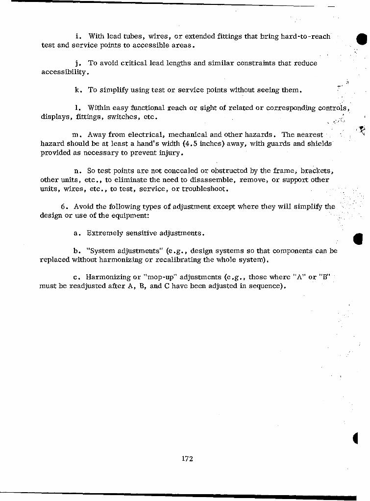
i. With lead tubes, wires, or extended fittings that bring hard-to -reachtest and service points to accessible areas.
j. To avoid critical lead lengths and similar constraints that reduceaccessibility.
k. To simplify using test or service points without seeing them.
1. Within easy functional reach or sight of related or corresponding controls,displays, fittings, switches, etc.
m. Away from electrical, mechanical and other hazards. The nearest "hazard should be at least a hand's width (4.5 inches) away, with guards and shieldsprovided as necessary to prevent injury.
n. So test points are not concealed or obstructed by the frame, brackets,other units, etc., to eliminate the need to disassemble, remove, or support otherunits, wires, etc., to test, service, or troubleshoot.
6. Avoid the following types of adjustment except where they will simplify the.
design or use of the equipment:
a. Extremely sensitive adjustments.
b. "System adjustments" (e.g., design systems so that components can bereplaced without harmonizing or recalibrating the whole system).
c. Harmonizing or "mop-up" adjustments (e.g., those where "A" or "B"must be readjusted after A, B, and C have been adjusted in sequence).
1172
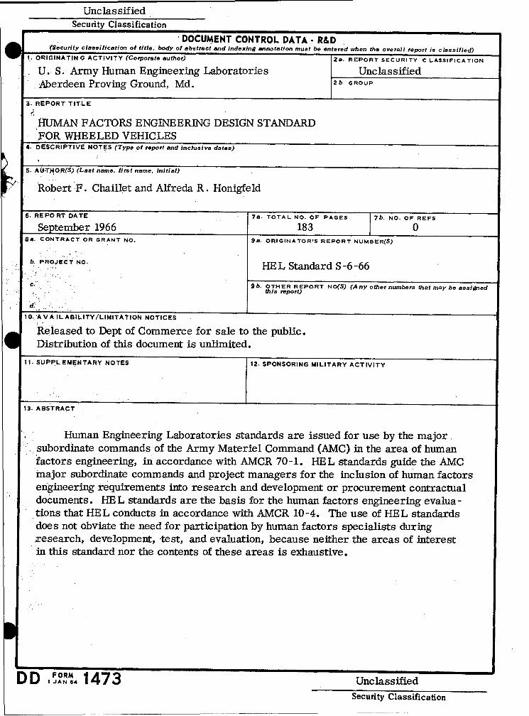
UnclassifiedSecurity Classification
"DOCUMENT CONTROL DATA- R&D(Security claesification of title, body of abstract and indexing annotation must be entered when the overall report is classified)
1.- ORIGINATING ACTIVITY (Corporate author) 28. REPORT SECURITY CLASSIFICATION
U. S. Army Human Engineering Laboratories UnclassifiedAberdeen Proving Ground, Md. 2b. GROUP
3. REPORT TITLE
14UMAN FACTORS ENGINEERING DESIGN STANDARDFOR WHEELED VEHICLES
4. DESCRIPTIVE NOTES (Type of report and inclusive dates)
5. AUTHOR(S) (Last name, first name, initial)
Robert F. Chaillet and Alfreda R. Honigfeld
6. REPORT DATE 7a. TOTAL NO. OF PAGES b- OF REPS
September 1966 183 08a. CONTRACT OR GRANT NO. 9a. ORIGINATOR'S REPORT NUMBER(S)
b. PROJECT NO.. E HE L Standard S -6 -66
C Sb. OTHER REPORT NO(S) (A ny other numbers that may be assignedthis report)
d.
10. A VA IL ABILITY/LIMITATION NOTICES
Released to Dept of Commerce for sale to the public.Distribution of this document is unlimited.
I I. SUPPL EMENTARY NOTES 12. SPONSORING MILITARY ACTIVITY
13. ABSTRACT
Human Engineering Laboratories standards are issued for use by the majorsubordinate commands of the Army Materiel Command (AMC) in the area of humanfactors engineering, in accordance with AMCR 70-1. HEL standards guide the AMCmajor subordinate commands and project managers for the inclusion of human factorsengineering requirements into research and development or procurement contractualdocuments. HE L standards are the basis for the human factors engineering evalua-tions that HEL conducts in accordance with AMCR 10-4. The use of HEL standardsdoes not obviate the need for participation by human factors specialists duringxesearch, development, test, and evaluation, because neither the areas of interestin this standard nor the contents of these areas is exhaustive.
FORM IA7DD, JAN.1473 UnclassifiedSecurity Classification

Security Classification4KEY WORDS LINK A LINK B LINK C
ROLE WT ROLE WT ROLE WT
INSTRUCTIONS
1. ORIGINATING ACTIVITY: Enter the name and address 10. AVAILABILITY/LIMITATION NOTICES: Enter any lir-of the contractor, subcontractor, grantee, Department of De- itations on further dissemination of the report, other than thosefense activity or other organization (corporate author) issuing imposed by security classification, using standard statementsthe report. suc as:such as:2a. REPORT SECURITY CLASSIFICATION: Enter the over- (1) "Qualified requesters may obtain copies of thisall security classification of the report. Indicate whether"Restricted Data" is included. Marking is to be in accord- report from DDC."ance with appropriate security regulations. (2) "Foreign announcement and dissemination of this2b. GROUP: Automatic downgrading is specified in DoD Di- report by DDC is not authorized."rective 5200.10 and Armed Forces Industrial Manual. Enter (3) "U. S. Government agencies may obtain copies ofthe group number. Also, when applicable, show thai optional this report directly from DDC. Other qualified DDCmarkings have been used for Group 3 and Group 4 as author- users shall request throughized.
3. REPORT TITLE: Enter the complete report title in all (4) "U. S. military agencies may obtain copies of thiscapital letters. Titles in all cases should be unclassified. report directly from DDC. Other qualified usersIf a meaningful title cannot be selected without classifica- shall request throughtion, show title classification in all capitals in parenthesisimmediately following the title. _"
4. DESCRIPTIVE NOTES: If appropriate, enter the type of (5) "All distribution of this report is controlled. Qual-report, e.g., interim, progress, summary, annual, or final. ified DDC users shall request throughGive the inclusive dates when a specific reporting period iscovered.
If the report has been furnished to the Office of Technical5. AUTHOR(S): Enter the name(s) of author(s) as shown on Services, Department of Commerce, for sale to the public, indi-or in the report. Enter last name, -first name, miiddle initial. cate this fact and enter the price, if known.If military, show rank and branch of service. The name ofthe principal author is an absolute minimum requirement. 11. SUPPLEMENTARY NOTES: Use for additional explana-6. REPORT DATE: Enter the date of the report as day, tory notes.month, year; or month, year. If more than one date appears 12. SPONSORING MILITARY ACTIVITY: Enter the name ofon the report, useidate of publication, the departmental project office or laboratory sponsoring (pay-7a. TOTAL NUMBER OF PAGES: The total page count ing for) the research" and development. Include address.should follow normal pagination proceduree, i.e., enter the 13. ABSTRACT: Enter an abstract giving a brief and factualnumber of pages containing information. summary of the document indicative of the report, even though
it may also appear elsewhere in the body of the technical re-7b. NUMBER OF REFERENCES: Enter the total number of port. If additional space is required, a continuation sheetreferences cited in the report. shall be attached.
8a. CONTRACT OR GRANT NUMBER: If appropriate, enter It is highly desirable that the abstract of classified re-the applicable number of the contract or.grant under which ports be unclassified, Each paragraph of the abstract shallthe report was written. end with an indication of the military security classification8b, 8c, & 8d. PROJECT NUMBER: Enter the appropriate of the information in the paragraph, represented as (TS), (S),military department identification, such as project number, (C), or (U).subproject number, system numbers, task number, etc. There is no limitation on the length of the abstract. How-9a. ORIGINATOR'S REPORT NUMBER(S): Enter the offi- ever, the suggested length is from 150 to 225 words.cial report number by which the document will be identified 14. KEY WORDS: Key words are technically meaningful termsand controlled by the originating activity. This number must or short phrases that characterize a report and may be" used asbe unique to this report. index entries for cataloging the report. Key words must be9b. OTHER REPORT NUMBER(S): If the report has been selected so that no security classification is required. Iden-assigned any other report numbers (either by the originator fiers, such as equipment model designation, trade name, mili-or by the sponsor), also enter this number(s). tary project code name, geographic location, may be used as
key words but will be followed 'by an indication of technicalcontext. The assignment of links, rules, and weights isoptional.
Security Classification