Embed Size (px)
Citation preview
415 T E C H N I C A L D A T A S H E E T
Primer for Polysulfide Sealants
B E N E F I T S
• One component
• Easy to apply
• Fast recoat time
R E C O M M E N D E D U S E S
• Used in conjunction with Thiokol sealants
G E N E R I C D E S C R I P T I O N
Primer
S T A N D A R D C O L O R S
Amber
P A C K A G I N G
1-Gallon Unit
C O V E R A G E
Concrete: 300 ft2 / gallon @ 3–5 mils
Steel: 400 ft2 / gallon @ 2–3 mils
D E S C R I P T I O N
Thiokol 415 Primer is a low viscosity primer for polysulfide sealants.
T Y P I C A L A P P L I C A T I O N
• Primer Thiokol 415 Primer @ 3–5 mils (concrete) / 2–3 mils (steel)
• Sealant Thiokol Sealant System
P E R F O R M A N C E D A T A
V O C . . . . . . . . . . . . . . . . . . . . . . . . . . . . . . . . . . . . . . . . . . . . . . . . . . . . . . . . . . . . . . . . . 6 . 5 l b / ga l ; 7 8 1 .5 g m / L
S T O R A G E & I N S T A L L A T I O N
St o r a g e E n v i r o n m e n t . . . . . . . . . . . . . . . . . . . . . . . . . . . . . . . . . . . . . . . . . . . . . . . . D r y a r e a , 6 5 – 8 0 º F A p p l i c a t i o n Te m p e r a t u r e , a mb i e n t . . . . . . . . . . . . . . . . . . . . . . . . . . . . . . . . . . . . . . . . . . . . 4 0 – 9 5 º F A p p l i c a t i o n Te m p e r a t u r e , s u b s t r a t e . . . . . . . . . . . . . M i n i m u m 5 º F a b o v e d e w p o i n t S h e l f L i f e . . . . . . . . . . . . . . . . . . . . . . . . . . . . . . . . . . . . . . . . . . . . . . . . . . . . . . . . . . . . . . . . . . . . . . . . . . . . . . . . 1 y e a r S e t T i me , @ 7 7 º F . . . . . . . . . . . . . . . . . . . . . . . . . . . . . . . . . . . . . . . . . . . . . . . . . . . . . . . . . . . . . . . 6 0 m i n u t e s
Material cures more slowly at cooler temperatures, and working time will be substantially reduced at higher temperatures. In hot weather, material should be cooled to 65ºF to 80ºF prior to mixing and application to improve workability and avoid shortened pot life. The data shown above reflects typical results based on laboratory testing under controlled conditions. Reasonable variations from the data shown above may result.
C O N S I D E R A T I O N S & L I M I T A T I O N S
1. Do not thin with solvents unless advised to do so by PolySpec. 2. Confirm product performance in specific chemical environment prior to use. 3. Prepare substrate according to “Surface Preparation” portion of this document. 4. Always use protective clothing, gloves and goggles consistent with OSHA
regulations during use. Avoid eye and skin contact. Do not ingest or inhale. Refer to Material Safety Data Sheet for detailed safety precautions.
5. For industrial/commercial use. Installation by trained personnel only.
PolySpec, L.P. warrants its products to be free from defects in material and workmanship. PolySpec's sole obligation and Buyer's exclusive remedy in connection with the products shall be limited, at PolySpec's option, to either replacement of products not conforming to this warranty or credit to Buyer's account in the invoiced amount of the nonconforming products. Any claim under this Warranty must be made by Buyer to PolySpec in writing within five days of Buyer's discovery of the claimed defect, but in no event later than the expiration of the applicable shelf life, or one year from the delivery date, whichever is earlier. Buyer's failure to notify PolySpec of such nonconformance as required herein shall bar Buyer from recovery under this warranty. PolySpec makes no other warranties concerning this product. No other warranties, either expressed or implied, or statutory, such as warranties of merchantability or fitness for a particular purpose, shall apply. In no event shall PolySpec be liable for consequential or incidental damages. Any recommendation or suggestion relating to the use of the products made by PolySpec, whether in its technical literature, or in response to specific inquiry, or otherwise, is based on data believed to be reliable; however, the products and information are intended for use by Buyers having requisite skill and know-how in the industry, and therefore it is for the Buyer to satisfy itself of the suitability of the products for its own particular use, and it shall be deemed that Buyer has done so, at its sole discretion and risk. Variation in environment changes in procedures of use, or extrapolation of data may cause unsatisfactory results. PolySpec cannot guarantee that color will conform to sample, if provided.
P O LY S P E C L . P. • 6 6 1 4 G A N T R O A D , H O U S T O N T E X A S 7 7 0 6 6 U S A • T: 2 8 1 . 3 9 7 . 0 0 3 3 • F : 2 8 1 . 3 9 7 . 6 5 1 2 • www.po l yspec .com
S U R F A C E P R E P A R A T I O N Concrete: Apply only to clean, dry and sound concrete substrates that are free of all coatings, sealers, curing compounds, oils, greases or any other contaminants. • New concrete should be cured a
minimum of 28 days. • Concrete that has been contaminated
with chemicals or other foreign matter must be neutralized or removed.
• Remove any laitance or weak surface layers.
• Concrete should have a minimum surface tensile strength of at least 300 PSI per ASTM D-4541.
• Surface profile shall be CSP-3 to CSP-5 meeting ICRI (International Concrete Repair Institute) standard guideline #03732 for coating concrete, producing a profile equal to 60-grit sandpaper or coarser. Prepare surface by mechanical means to achieve this desired profile.
• Moisture vapor transmission should be 3 pounds or less per 1,000 square feet over a 24 hour time period, as confirmed through a calcium chloride test, as per ASTM E-1907. Quantitative relative humidity (RH) testing, ASTM F-2170, should confirm concrete RH results <75%.
• All surface irregularities, cracks, expansion joints and control joints should be properly addressed prior to application.
• Outgassing may occur due to the porosity of some concrete surfaces. To reduce the effect of outgassing, the primer and coating should be applied when the temperature of the concrete substrate is dropping. This usually occurs in the evening; however, the concrete substrate temperature should be measured with a surface thermometer for verification. Double priming will greatly reduce the effects of outgassing by additionally filling the pores in the concrete.
Steel: For immersion service, “White Metal” abrasive blast with an anchor profile of 2–4 mils in accordance with Steel Structures Painting Council Specification SP-5-63 or NACE No. 1 is required. For splash and spillage exposure, “Near White” SP-10-63 or NACE No. 2 is required.
Refer to PolySpec Surface Preparation Guidelines for more details.
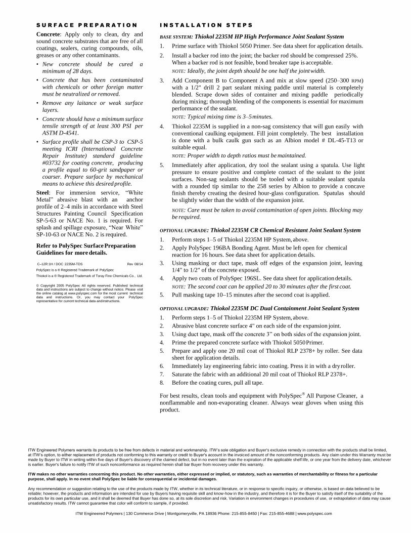
I N S T A L L A T I O N S T E P S
1. Thiokol 415 Primer can be applied by spray, brush or roller. NOTE: Use of a brush will allow for joints to be primed before the application
of Thiokol sealants.
Spray Application: Apply Thiokol 415 primer in a spray mist-coat at a rate not to exceed the following:
• Concrete:............. 300 ft2/gallon maximum • Steel: .................. 400 ft2/gallon maximum
Brush or Roller Application: Thiokol 415 may be applied by brush or roller; however, coverage will be significantly reduced.
• Concrete:............. 3–5 mils • Steel: .................. 2–3 mils
2. Allow primer to cure until it is dry to the touch (typically 1 hour @ 77ºF) before proceeding to application of Thiokol sealant.
3. For best results, clean tools and equipment with PolySpec® All Purpose Cleaner, a nonflammable and non-evaporating cleaner. Always wear gloves when using this product.
Premixed / DOC 415-TDS Rev 03/05
Thiokol is a ® Registered Trademark of Toray Fine Chemicals Co., Ltd.
© Copyright 2005 PolySpec L.P. All rights reserved. Published technical data and instructions are subject to change without notice. Please visit the online catalog at www.polyspec.com for the most current technical data and instructions. Or, you may contact your PolySpec representative for current technical data and instructions.
D E S C R I P T I O N
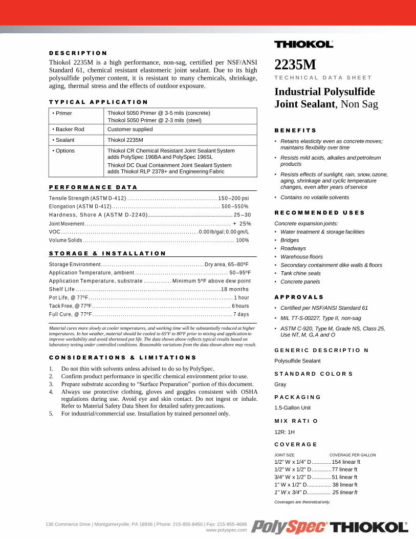
Thiokol 2235M is a high performance, non-sag, certified per NSF/ANSI
Standard 61, chemical resistant elastomeric joint sealant. Due to its high
polysulfide polymer content, it is resistant to many chemicals, shrinkage,
aging, thermal stress and the effects of outdoor exposure.
T Y P I C A L A P P L I C A T I O N
• Primer Thiokol 5050 Primer @ 3-5 mils (concrete)
Thiokol 5050 Primer @ 2-3 mils (steel)
• Backer Rod Customer supplied
• Sealant Thiokol 2235M
• Options Thiokol CR Chemical Resistant Joint Sealant System adds PolySpec 196BA and PolySpec 196SL
Thiokol DC Dual Containment Joint Sealant System adds Thiokol RLP 2378+ and Engineering Fabric
P E R F O R M A N C E D A T A
Te n s i l e St r e n g t h ( A S T M D - 412) . . . . . . . . . . . . . . . . . . . . . . . . . . . . . . . . . . . . . . . . . . . 150 – 2 0 0 p s i
E l o n g a t i o n ( A S T M D - 4 1 2 ) . . . . . . . . . . . . . . . . . . . . . . . . . . . . . . . . . . . . . . . . . . . . . . . . . . . . . . 500 – 5 5 0 %
H a r d n e s s , S h o r e A ( A S T M D - 2 2 4 0 ) ................................................................. 25 – 30
J o i n t M o v e m e n t . . . . . . . . . . . . . . . . . . . . . . . . . . . . . . . . . . . . . . . . . . . . . . . . . . . . . . . . . . . . . . . . . . . . . . . . 25%
V O C . . . . . . . . . . . . . . . . . . . . . . . . . . . . . . . . . . . . . . . . . . . . . . . . . . . . . . . . . . . . . . . . . 0 . 0 0 l b / g a l ; 0 . 0 0 g m / L
Vo l u m e S o l i d s . . . . . . . . . . . . . . . . . . . . . . . . . . . . . . . . . . . . . . . . . . . . . . . . . . . . . . . . . . . . . . . . . . . . . . . . . . . 1 0 0 %
S T O R A G E & I N S T A L L A T I O N
St o r a g e E n v i r o n m e n t . . . . . . . . . . . . . . . . . . . . . . . . . . . . . . . . . . . . . . . . . . . . . . . . . D r y a r e a , 6 5 – 8 0 º F
A p p l i c a t i o n Te m p e r a t u r e , a m b i e n t . . . . . . . . . . . . . . . . . . . . . . . . . . . . . . . . . . . . . . . . . . . . 50 – 9 5 º F
A p p l i c a t i o n Te m p e r a t u r e , s u b s t r a t e . . . . . . . . . . . . . M i n i m u m 5 º F a b o v e d e w p o i n t
S h e l f L i f e . . . . . . . . . . . . . . . . . . . . . . . . . . . . . . . . . . . . . . . . . . . . . . . . . . . . . . . . . . . . . . . . . . . . . . . . . . . 1 8 m o n t h s
P o t L i f e , @ 7 7 º F . . . . . . . . . . . . . . . . . . . . . . . . . . . . . . . . . . . . . . . . . . . . . . . . . . . . . . . . . . . . . . . . . . . . . . . 1 h o u r
Ta c k F r e e , @ 7 7 º F . . . . . . . . . . . . . . . . . . . . . . . . . . . . . . . . . . . . . . . . . . . . . . . . . . . . . . . . . . . . . . . . .. 6 h o u r s
F u l l C u r e , @ 7 7 º F . . . . . . . . . . . . . . . . . . . . . . . . . . . . . . . . . . . . . . . . . . . . . . . . . . . . . . . . . . . . . . . . . . . . . 7 d a y s
Material cures more slowly at cooler temperatures, and working time will be substantially reduced at higher
temperatures. In hot weather, material should be cooled to 65ºF to 80ºF prior to mixing and application to
improve workability and avoid shortened pot life. The data shown above reflects typical results based on
laboratory testing under controlled conditions. Reasonable variations from the data shown above may result.
C O N S I D E R A T I O N S & L I M I T A T I O N S
1. Do not thin with solvents unless advised to do so by PolySpec.
2. Confirm product performance in specific chemical environment prior to use.
3. Prepare substrate according to “Surface Preparation” portion of this document.
4. Always use protective clothing, gloves and goggles consistent with OSHA
regulations during use. Avoid eye and skin contact. Do not ingest or inhale.
Refer to Material Safety Data Sheet for detailed safety precautions.
5. For industrial/commercial use. Installation by trained personnel only.
2235M T E C H N I C A L D A T A S H E E T
Industrial Polysulfide
Joint Sealant, Non Sag
B E N E F I T S
• Retains elasticity even as concrete moves; maintains flexibility over time
• Resists mild acids, alkalies and petroleum products
• Resists effects of sunlight, rain, snow, ozone, aging, shrinkage and cyclic temperature changes, even after years of service
• Contains no volatile solvents
R E C O M M E N D E D U S E S
Concrete expansion joints:
• Water treatment & storage facilities
• Bridges
• Roadways
• Warehouse floors
• Secondary containment dike walls & floors
• Tank chine seals
• Concrete panels
A P P R O V A L S
• Certified per NSF/ANSI Standard 61
• MIL TT-S-00227, Type II, non-sag
• ASTM C-920, Type M, Grade NS, Class 25, Use NT, M, G, A and O
G E N E R I C D E S C R I P T I O N
Polysulfide Sealant
S T A N D A R D C O L O R S
Gray
P A C K A G I N G
1.5-Gallon Unit
M I X R A T I O
12R: 1H
C O V E R A G E
JOINT SIZE COVERAGE PER GALLON
1/2" W x 1/4" D ............. 154 linear ft
1/2" W x 1/2" D ............. 77 linear ft
3/4" W x 1/2" D ............. 51 linear ft
1" W x 1/2" D................ 38 linear ft
1" W x 3/4" D................ 25 linear ft
Coverages are theoretical only.
130 Commerce Drive | Montgomeryville, PA 18936 | Phone: 215-855-8450 | Fax: 215-855-4688
www.polyspec.com
S U R F A C E P R E P A R A T I O N
Concrete: Apply only to clean, dry and
sound concrete substrates that are free of all
coatings, sealers, curing compounds, oils,
greases or any other contaminants.
• New concrete should be cured a
minimum of 28 days.
• Concrete that has been contaminated
with chemicals or other foreign matter
must be neutralized or removed.
• Remove any laitance or weak surface
layers.
• Concrete should have a minimum surface
tensile strength of at least 300 PSI per
ASTM D-4541.
• Surface profile shall be CSP-3 to CSP-5
meeting ICRI (International Concrete
Repair Institute) standard guideline
#03732 for coating concrete, producing
a profile equal to 60-grit sandpaper or
coarser. Prepare surface by mechanical
means to achieve this desired profile.
Steel: For immersion service, “White
Metal” abrasive blast with an anchor
profile of 2–4 mils in accordance with Steel
Structures Painting Council Specification
SP-5-63 or NACE No. 1 is required. For
splash and spillage exposure, “Near White”
SP-10-63 or NACE No. 2 is required.
Refer to PolySpec Surface Preparation
Guidelines for more details.
C–12R:1H / DOC 2235M-TDS Rev 08/14
PolySpec is a ® Registered Trademark of PolySpec
Thiokol is a ® Registered Trademark of Toray Fine Chemicals Co., Ltd.
© Copyright 2005 PolySpec All rights reserved. Published technical data and instructions are subject to change without notice. Please visit the online catalog at www.polyspec.com for the most current technical data and instructions. Or, you may contact your PolySpec representative for current technical data and instructions.
I N S T A L L A T I O N S T E P S
BASE SYSTEM: Thiokol 2235M HP High Performance Joint Sealant System
1. Prime surface with Thiokol 5050 Primer. See data sheet for application details.
2. Install a backer rod into the joint; the backer rod should be compressed 25%.
When a backer rod is not feasible, bond breaker tape is acceptable.
NOTE: Ideally, the joint depth should be one half the joint width.
3. Add Component B to Component A and mix at slow speed (250–300 RPM)
with a 1/2" drill 2 part sealant mixing paddle until material is completely
blended. Scrape down sides of container and mixing paddle periodically
during mixing; thorough blending of the components is essential for maximum
performance of the sealant.
NOTE: Typical mixing time is 3–5 minutes.
4. Thiokol 2235M is supplied in a non-sag consistency that will gun easily with
conventional caulking equipment. Fill joint completely. The best installation
is done with a bulk caulk gun such as an Albion model # DL-45-T13 or
suitable equal.
NOTE: Proper width to depth ratios must be maintained.
5. Immediately after application, dry tool the sealant using a spatula. Use light
pressure to ensure positive and complete contact of the sealant to the joint
surfaces. Non-sag sealants should be tooled with a suitable sealant spatula
with a rounded tip similar to the 258 series by Albion to provide a concave
finish thereby creating the desired hour-glass configuration. Spatulas should
be slightly wider than the width of the expansion joint.
NOTE: Care must be taken to avoid contamination of open joints. Blocking may
be required.
OPTIONAL UPGRADE: Thiokol 2235M CR Chemical Resistant Joint Sealant System
1. Perform steps 1–5 of Thiokol 2235M HP System, above.
2. Apply PolySpec 196BA Bonding Agent. Must be left open for chemical
reaction for 16 hours. See data sheet for application details.
3. Using masking or duct tape, mask off edges of the expansion joint, leaving
1/4" to 1/2" of the concrete exposed.
4. Apply two coats of PolySpec 196SL. See data sheet for application details.
NOTE: The second coat can be applied 20 to 30 minutes after the first coat.
5. Pull masking tape 10–15 minutes after the second coat is applied.
OPTIONAL UPGRADE: Thiokol 2235M DC Dual Containment Joint Sealant System
1. Perform steps 1–5 of Thiokol 2235M HP System, above.
2. Abrasive blast concrete surface 4" on each side of the expansion joint.
3. Using duct tape, mask off the concrete 3” on both sides of the expansion joint.
4. Prime the prepared concrete surface with Thiokol 5050 Primer.
5. Prepare and apply one 20 mil coat of Thiokol RLP 2378+ by roller. See data
sheet for application details.
6. Immediately lay engineering fabric into coating. Press it in with a dry roller.
7. Saturate the fabric with an additional 20 mil coat of Thiokol RLP 2378+.
8. Before the coating cures, pull all tape.
For best results, clean tools and equipment with PolySpec® All Purpose Cleaner, a
nonflammable and non-evaporating cleaner. Always wear gloves when using this
product.
ITW Engineered Polymers warrants its products to be free from defects in material and workmanship. ITW’s sole obligation and Buyer's exclusive remedy in connection with the products shall be limited,
at ITW’s option, to either replacement of products not conforming to this warranty or credit to Buyer's account in the invoiced amount of the nonconforming products. Any claim under this Warranty must be
made by Buyer to ITW in writing within five days of Buyer's discovery of the claimed defect, but in no event later than the expiration of the applicable shelf life, or one year from the delivery date, whichever
is earlier. Buyer's failure to notify ITW of such nonconformance as required herein shall bar Buyer from recovery under this warranty.
ITW makes no other warranties concerning this product. No other warranties, either expressed or implied, or statutory, such as warranties of merchantability or fitness for a particular
purpose, shall apply. In no event shall PolySpec be liable for consequential or incidental damages.
Any recommendation or suggestion relating to the use of the products made by ITW, whether in its technical literature, or in response to specific inquiry, or otherwise, is based on data believed to be
reliable; however, the products and information are intended for use by Buyers having requisite skill and know-how in the industry, and therefore it is for the Buyer to satisfy itself of the suitability of the
products for its own particular use, and it shall be deemed that Buyer has done so, at its sole discretion and risk. Variation in environment changes in procedures of use, or extrapolation of data may cause
unsatisfactory results. ITW cannot guarantee that color will conform to sample, if provided.
ITW Engineered Polymers | 130 Commerce Drive | Montgomeryville, PA 18936 Phone: 215-855-8450 | Fax: 215-855-4688 | www.polyspec.com

Hilti HIT-HY 150 MAX with rebar
09 / 2012
602
Hilti HIT-HY 150 MAX with rebar
Injection mortar system Benefits
Hilti HIT- HY 150 MAX 330 ml foil pack
(also available as 500 ml and 1400 ml foil pack)
- suitable for non-cracked and cracked concrete C 20/25 to C 50/60
- suitable for dry and water saturated concrete
- high loading capacity - rapid curing - small edge distance and anchor
spacing possible - large diameter applications - in service temperature range up
to 120°C short term/72°C long term
- manual cleaning for anchor size Ø8 to Ø14 and embedment depth hef ≤ 10d for non-cracked concrete
- embedment depth range: from 60 ... 160 mm for Ø8 to 100 ... 500 mm for Ø25
Static mixer
rebar BSt 500 S
Concrete Tensile zone
Small edge distance
and spacing
Variable embedment
depth
European Technical Approval
CE conformity
PROFIS Anchor design software
Approvals / certificates Description Authority / Laboratory No. / date of issue European technical approval a) DIBt, Berlin ETA-08/0352 / 2010-04-01
a) All data given in this section according ETA-08/0352 issue 2010-04-01. Basic loading data (for a single anchor) All data in this section applies to For details see Simplified design method - Correct setting (See setting instruction) - No edge distance and spacing influence - Steel failure - Base material thickness, as specified in the table - One typical embedment depth, as specified in the table - Anchor material: rebar BSt 500 S - Concrete C 20/25, fck,cube = 25 N/mm² - Temperate range I
(min. base material temperature -40°C, max. long ter m/short term base material temperature: +24°C/40°C) - Installation temperature range -10°C to +40°C
Hilti HIT-HY 150 MAX with rebar
09 / 2012
603
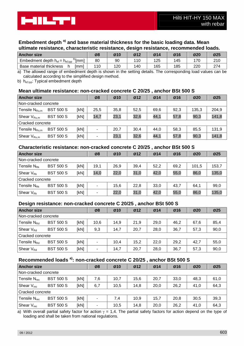
Embedment depth a) and base material thickness for the basic loading d ata. Mean ultimate resistance, characteristic resistance, des ign resistance, recommended loads. Anchor size Ø8 Ø10 Ø12 Ø14 Ø16 Ø20 Ø25 Embedment depth hef = hef,typ
b)[mm] 80 90 110 125 145 170 210 Base material thickness h [mm] 110 120 140 165 185 220 274
a) The allowed range of embedment depth is shown in the setting details. The corresponding load values can be calculated according to the simplified design method.
b) hef,typ: Typical embedment depth Mean ultimate resistance: non -cracked concrete C 20/25 , anchor BSt 500 S Anchor size Ø8 Ø10 Ø12 Ø14 Ø16 Ø20 Ø25 Non-cracked concrete
Tensile NRu,m BST 500 S [kN] 25,5 35,8 52,5 69,6 92,3 135,3 204,9
Shear VRu,m BST 500 S [kN] 14,7 23,1 32,6 44,1 57,8 90,3 141,8
Cracked concrete
Tensile NRu,m BST 500 S [kN] - 20,7 30,4 44,0 58,3 85,5 131,9
Shear VRu,m BST 500 S [kN] - 23,1 32,6 44,1 57,8 90,3 141,8
Characteristic resistance: non -cracked concrete C 20/25 , anchor B St 500 S Anchor size Ø8 Ø10 Ø12 Ø14 Ø16 Ø20 Ø25 Non-cracked concrete
Tensile NRk BST 500 S [kN] 19,1 26,9 39,4 52,2 69,2 101,5 153,7
Shear VRk BST 500 S [kN] 14,0 22,0 31,0 42,0 55,0 86,0 135,0
Cracked concrete
Tensile NRk BST 500 S [kN] - 15,6 22,8 33,0 43,7 64,1 99,0
Shear VRk BST 500 S [kN] - 22,0 31,0 42,0 55,0 86,0 135,0
Design resistance: non -cracked concrete C 20/25 , anchor BSt 500 S Anchor size Ø8 Ø10 Ø12 Ø14 Ø16 Ø20 Ø25 Non-cracked concrete
Tensile NRd BST 500 S [kN] 10,6 14,9 21,9 29,0 46,2 67,6 85,4
Shear VRd BST 500 S [kN] 9,3 14,7 20,7 28,0 36,7 57,3 90,0
Cracked concrete
Tensile NRd BST 500 S [kN] - 10,4 15,2 22,0 29,2 42,7 55,0
Shear VRd BST 500 S [kN] - 14,7 20,7 28,0 36,7 57,3 90,0 Recommended loads a): non -cracked concrete C 20/25 , anchor BSt 500 S Anchor size Ø8 Ø10 Ø12 Ø14 Ø16 Ø20 Ø25 Non-cracked concrete
Tensile Nrec BST 500 S [kN] 7,6 10,7 15,6 20,7 33,0 48,3 61,0
Shear Vrec BST 500 S [kN] 6,7 10,5 14,8 20,0 26,2 41,0 64,3
Cracked concrete
Tensile Nrec BST 500 S [kN] - 7,4 10,9 15,7 20,8 30,5 39,3
Shear Vrec BST 500 S [kN] - 10,5 14,8 20,0 26,2 41,0 64,3
a) With overall partial safety factor for action γ = 1,4. The partial safety factors for action depend on the type of loading and shall be taken from national regulations.
Hilti HIT-HY 150 MAX with rebar
09 / 2012
604
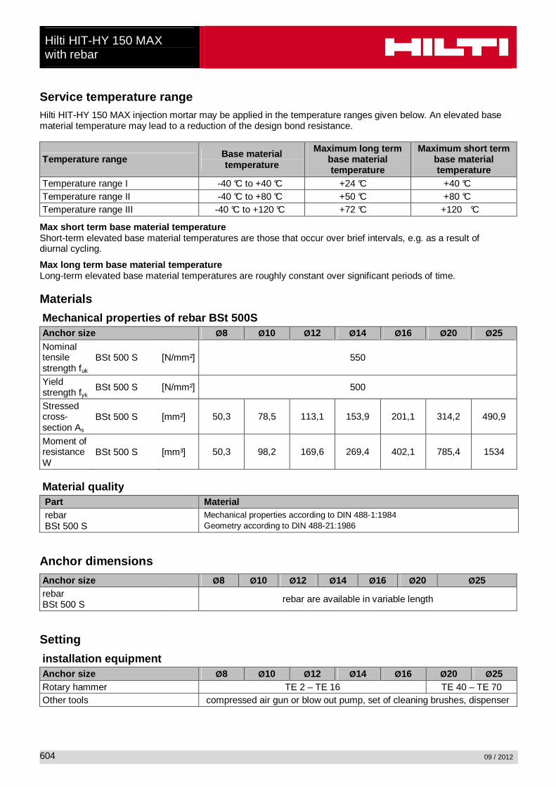
Service temperature range Hilti HIT-HY 150 MAX injection mortar may be applied in the temperature ranges given below. An elevated base material temperature may lead to a reduction of the design bond resistance.
Temperature range Base material temperature
Maximum long term base material temperature
Maximum short term base material temperature
Temperature range I -40 °C to +40 °C +24 °C +40 °C Temperature range II -40 °C to +80 °C +50 °C +80 °C Temperature range III -40 °C to +120 °C +72 °C +120 °C
Max short term base material temperature Short-term elevated base material temperatures are those that occur over brief intervals, e.g. as a result of diurnal cycling.
Max long term base material temperature Long-term elevated base material temperatures are roughly constant over significant periods of time. Materials
Mechanical properties of rebar BSt 500S Anchor size Ø8 Ø10 Ø12 Ø14 Ø16 Ø20 Ø25 Nominal tensile strength fuk
BSt 500 S [N/mm²] 550
Yield strength fyk
BSt 500 S [N/mm²] 500
Stressed cross-section As
BSt 500 S [mm²] 50,3 78,5 113,1 153,9 201,1 314,2 490,9
Moment of resistance W
BSt 500 S [mm³] 50,3 98,2 169,6 269,4 402,1 785,4 1534
Material quality Part Material rebar BSt 500 S
Mechanical properties according to DIN 488-1:1984 Geometry according to DIN 488-21:1986
Anchor dimensions
Anchor size Ø8 Ø10 Ø12 Ø14 Ø16 Ø20 Ø25 rebar BSt 500 S rebar are available in variable length
Setting
installation equipment Anchor size Ø8 Ø10 Ø12 Ø14 Ø16 Ø20 Ø25 Rotary hammer TE 2 – TE 16 TE 40 – TE 70 Other tools compressed air gun or blow out pump, set of cleaning brushes, dispenser
Hilti HIT-HY 150 MAX with rebar
09 / 2012
605
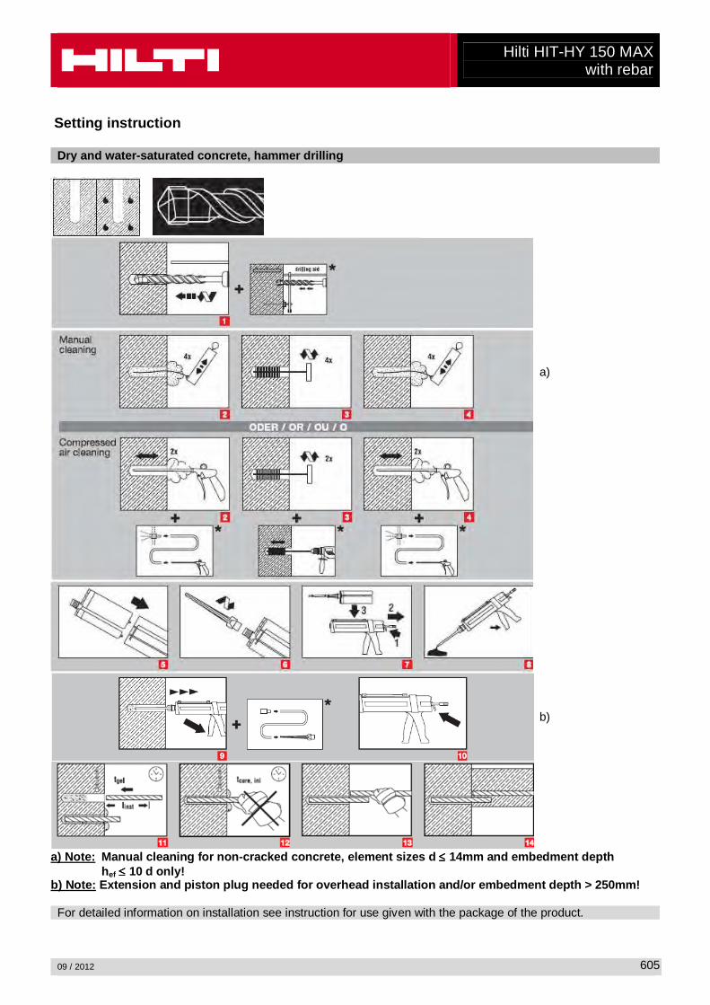
Setting instruction Dry and water-saturated concrete, hammer drilling
a)
b)
a) Note: Manual cleaning for non-cracked concrete, element sizes d ≤≤≤≤ 14mm and embedment depth hef ≤≤≤≤ 10 d only! b) Note: Extension and piston plug needed for overh ead installation and/or embedment depth > 250mm! For detailed information on installation see instruction for use given with the package of the product.
Hilti HIT-HY 150 MAX with rebar
09 / 2012
606
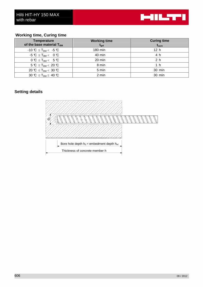
Working time, Curing time Temperature
of the base material T BM Working time
tgel Curing time
tcure -10 °C ≤ TBM < -5 °C 180 min 12 h
-5 °C ≤ TBM < 0 °C 40 min 4 h
0 °C ≤ TBM < 5 °C 20 min 2 h
5 °C ≤ TBM < 20 °C 8 min 1 h
20 °C ≤ TBM < 30 °C 5 min 30 min
30 °C ≤ TBM ≤ 40 °C 2 min 30 min Setting details
d 0
Bore hole depth h0 = embedment depth hef
Thickness of concrete member h
Hilti HIT-HY 150 MAX with rebar
09 / 2012
607
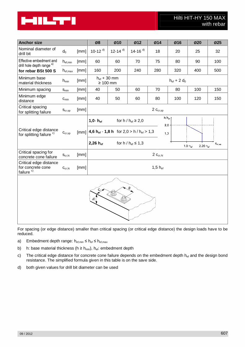
Anchor size Ø8 Ø10 Ø12 Ø14 Ø16 Ø20 Ø25
Nominal diameter of drill bit
d0 [mm] 10-12 d) 12-14 d) 14-16 d) 18 20 25 32
Effective embedment and drill hole depth range
a)
for rebar BSt 500 S
hef,min [mm] 60 60 70 75 80 90 100
hef,max [mm] 160 200 240 280 320 400 500
Minimum base material thickness
hmin [mm] hef + 30 mm ≥ 100 mm
hef + 2 d0
Minimum spacing smin [mm] 40 50 60 70 80 100 150
Minimum edge distance cmin [mm] 40 50 60 80 100 120 150
Critical spacing for splitting failure
scr,sp [mm] 2 ccr,sp
Critical edge distance for splitting failure c) ccr,sp [mm]
1,0 ⋅⋅⋅⋅ hef for h / hef ≥ 2,0
4,6 hef - 1,8 h for 2,0 > h / hef > 1,3
2,26 hef for h / hef ≤ 1,3
Critical spacing for concrete cone failure scr,N [mm] 2 ccr,N
Critical edge distance for concrete cone failure c)
ccr,N [mm] 1,5 hef
For spacing (or edge distance) smaller than critical spacing (or critical edge distance) the design loads have to be reduced.
a) Embedment depth range: hef,min ≤ hef ≤ hef,max
b) h: base material thickness (h ≥ hmin), hef: embedment depth
c) The critical edge distance for concrete cone failure depends on the embedment depth hef and the design bond resistance. The simplified formula given in this table is on the save side.
d) both given values for drill bit diameter can be used
Hilti HIT-HY 150 MAX with rebar
09 / 2012
608
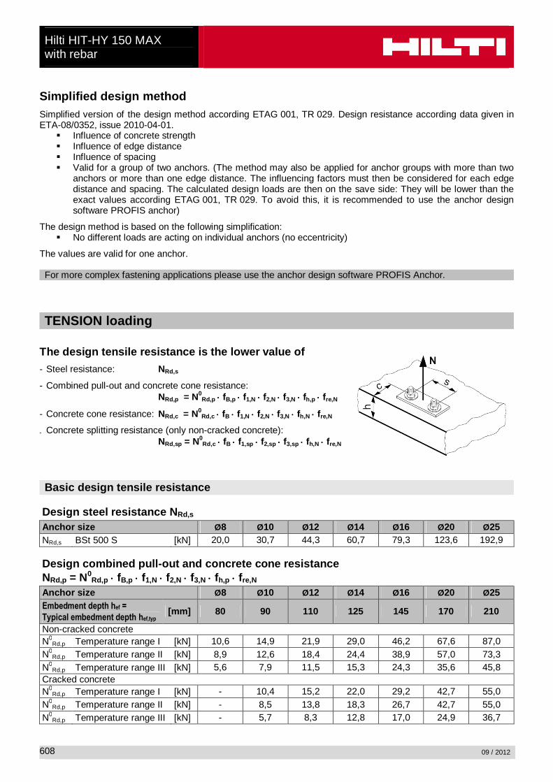
Simplified design method Simplified version of the design method according ETAG 001, TR 029. Design resistance according data given in ETA-08/0352, issue 2010-04-01.
� Influence of concrete strength � Influence of edge distance � Influence of spacing � Valid for a group of two anchors. (The method may also be applied for anchor groups with more than two
anchors or more than one edge distance. The influencing factors must then be considered for each edge distance and spacing. The calculated design loads are then on the save side: They will be lower than the exact values according ETAG 001, TR 029. To avoid this, it is recommended to use the anchor design software PROFIS anchor)
The design method is based on the following simplification: � No different loads are acting on individual anchors (no eccentricity)
The values are valid for one anchor. For more complex fastening applications please use the anchor design software PROFIS Anchor.
TENSION loading
The design tensile resistance is the lower value of
- Steel resistance: NRd,s
- Combined pull-out and concrete cone resistance: NRd,p = N0
Rd,p ⋅⋅⋅⋅ fB,p ⋅⋅⋅⋅ f1,N ⋅⋅⋅⋅ f2,N ⋅⋅⋅⋅ f3,N ⋅⋅⋅⋅ fh,p ⋅⋅⋅⋅ fre,N
- Concrete cone resistance: NRd,c = N0Rd,c ⋅⋅⋅⋅ fB ⋅⋅⋅⋅ f1,N ⋅⋅⋅⋅ f2,N ⋅⋅⋅⋅ f3,N ⋅⋅⋅⋅ fh,N ⋅⋅⋅⋅ fre,N
- Concrete splitting resistance (only non-cracked concrete): NRd,sp = N0
Rd,c ⋅⋅⋅⋅ fB ⋅⋅⋅⋅ f1,sp ⋅⋅⋅⋅ f2,sp ⋅⋅⋅⋅ f3,sp ⋅⋅⋅⋅ fh,N ⋅⋅⋅⋅ fre,N
Basic design tensile resistance
Design steel resistance N Rd,s Anchor size Ø8 Ø10 Ø12 Ø14 Ø16 Ø20 Ø25 NRd,s BSt 500 S [kN] 20,0 30,7 44,3 60,7 79,3 123,6 192,9
Design combined pull -out and concrete cone re sistance NRd,p = N0
Rd,p ⋅⋅⋅⋅ fB,p ⋅⋅⋅⋅ f1,N ⋅⋅⋅⋅ f2,N ⋅⋅⋅⋅ f3,N ⋅⋅⋅⋅ fh,p ⋅⋅⋅⋅ fre,N Anchor size Ø8 Ø10 Ø12 Ø14 Ø16 Ø20 Ø25 Embedment depth hef =
Typical embedment depth hef,typ [mm] 80 90 110 125 145 170 210
Non-cracked concrete N0
Rd,p Temperature range I [kN] 10,6 14,9 21,9 29,0 46,2 67,6 87,0 N0
Rd,p Temperature range II [kN] 8,9 12,6 18,4 24,4 38,9 57,0 73,3 N0
Rd,p Temperature range III [kN] 5,6 7,9 11,5 15,3 24,3 35,6 45,8 Cracked concrete N0
Rd,p Temperature range I [kN] - 10,4 15,2 22,0 29,2 42,7 55,0 N0
Rd,p Temperature range II [kN] - 8,5 13,8 18,3 26,7 42,7 55,0 N0
Rd,p Temperature range III [kN] - 5,7 8,3 12,8 17,0 24,9 36,7
Hilti HIT-HY 150 MAX with rebar
09 / 2012
609
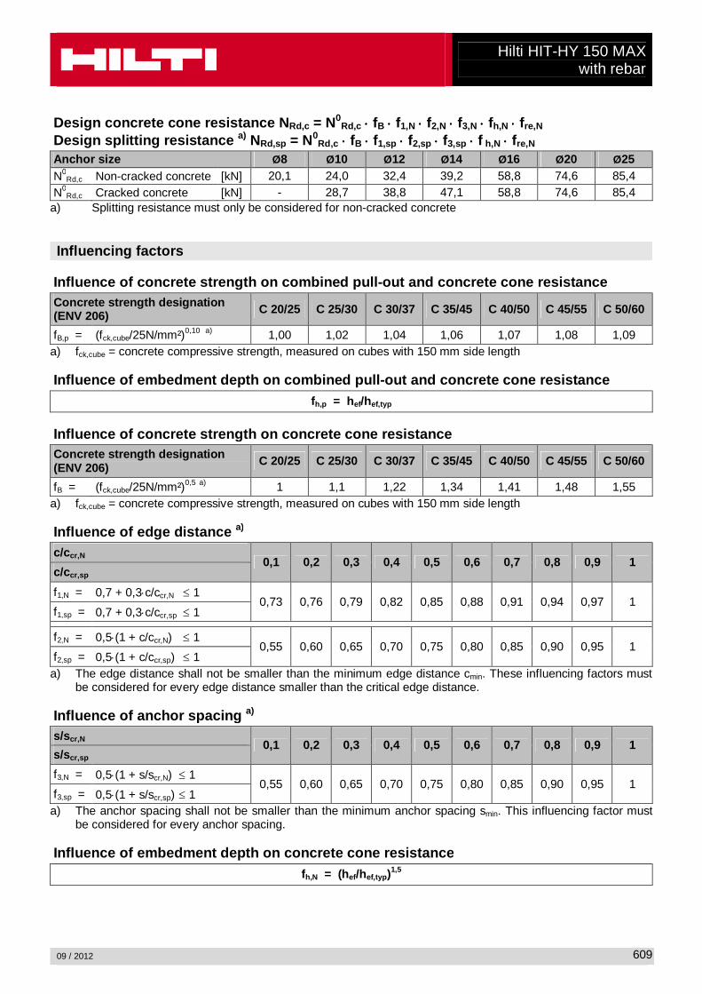
Design concrete cone resistance N Rd,c = N0Rd,c ⋅⋅⋅⋅ fB ⋅⋅⋅⋅ f1,N ⋅⋅⋅⋅ f2,N ⋅⋅⋅⋅ f3,N ⋅⋅⋅⋅ fh,N ⋅⋅⋅⋅ fre,N
Design splitting resistance a) NRd,sp = N0Rd,c ⋅⋅⋅⋅ fB ⋅⋅⋅⋅ f1,sp ⋅⋅⋅⋅ f2,sp ⋅⋅⋅⋅ f3,sp ⋅⋅⋅⋅ f h,N ⋅⋅⋅⋅ fre,N
Anchor size Ø8 Ø10 Ø12 Ø14 Ø16 Ø20 Ø25 N0
Rd,c Non-cracked concrete [kN] 20,1 24,0 32,4 39,2 58,8 74,6 85,4 N0
Rd,c Cracked concrete [kN] - 28,7 38,8 47,1 58,8 74,6 85,4 a) Splitting resistance must only be considered for non-cracked concrete Influencing factors
Influence of concrete strength on combined pull -out and concrete cone resistance
Concrete strength designation (ENV 206) C 20/25 C 25/30 C 30/37 C 35/45 C 40/50 C 45/55 C 50/60
fB,p = (fck,cube/25N/mm²)0,10 a) 1,00 1,02 1,04 1,06 1,07 1,08 1,09 a) fck,cube = concrete compressive strength, measured on cubes with 150 mm side length Influence of embedment depth on combined pull -out and concrete cone resistance
fh,p = hef/hef,typ
Influence of concrete strength on concrete cone resistance
Concrete strength designation (ENV 206)
C 20/25 C 25/30 C 30/37 C 35/45 C 40/50 C 45/55 C 50/60
fB = (fck,cube/25N/mm²)0,5 a) 1 1,1 1,22 1,34 1,41 1,48 1,55 a) fck,cube = concrete compressive strength, measured on cubes with 150 mm side length Influence of edge distance a)
c/c cr,N 0,1 0,2 0,3 0,4 0,5 0,6 0,7 0,8 0,9 1
c/c cr,sp
f1,N = 0,7 + 0,3⋅c/ccr,N ≤ 1 0,73 0,76 0,79 0,82 0,85 0,88 0,91 0,94 0,97 1
f1,sp = 0,7 + 0,3⋅c/ccr,sp ≤ 1
f2,N = 0,5⋅(1 + c/ccr,N) ≤ 1 0,55 0,60 0,65 0,70 0,75 0,80 0,85 0,90 0,95 1
f2,sp = 0,5⋅(1 + c/ccr,sp) ≤ 1 a) The edge distance shall not be smaller than the minimum edge distance cmin. These influencing factors must
be considered for every edge distance smaller than the critical edge distance. Influence of anchor spacing a)
s/s cr,N 0,1 0,2 0,3 0,4 0,5 0,6 0,7 0,8 0,9 1
s/s cr,sp
f3,N = 0,5⋅(1 + s/scr,N) ≤ 1 0,55 0,60 0,65 0,70 0,75 0,80 0,85 0,90 0,95 1
f3,sp = 0,5⋅(1 + s/scr,sp) ≤ 1 a) The anchor spacing shall not be smaller than the minimum anchor spacing smin. This influencing factor must
be considered for every anchor spacing. Influence of embedment depth on concrete cone resis tance
fh,N = (hef/hef,typ )1,5
Hilti HIT-HY 150 MAX with rebar
09 / 2012
610
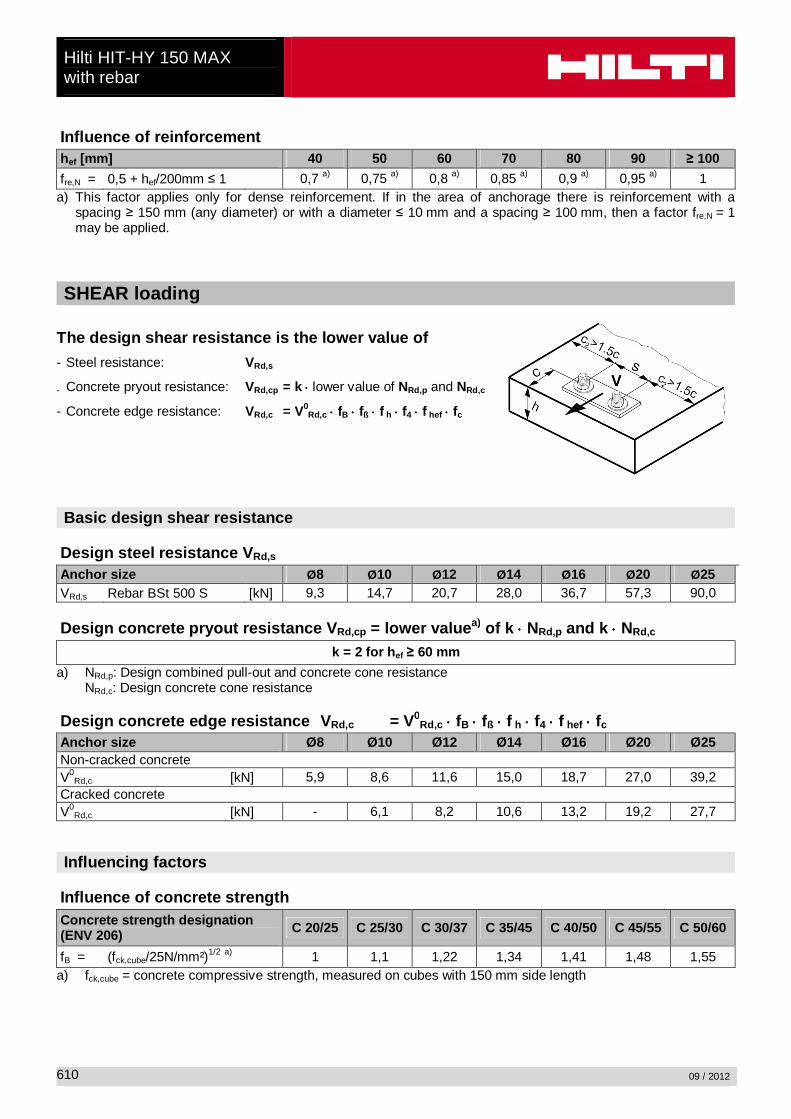
Influence of reinforcement
hef [mm] 40 50 60 70 80 90 ≥ 100
fre,N = 0,5 + hef/200mm ≤ 1 0,7 a) 0,75 a) 0,8 a) 0,85 a) 0,9 a) 0,95 a) 1 a) This factor applies only for dense reinforcement. If in the area of anchorage there is reinforcement with a
spacing ≥ 150 mm (any diameter) or with a diameter ≤ 10 mm and a spacing ≥ 100 mm, then a factor fre,N = 1 may be applied.
SHEAR loading
The design shear resistance is the lower value of
- Steel resistance: VRd,s
- Concrete pryout resistance: VRd,cp = k ⋅⋅⋅⋅ lower value of NRd,p and NRd,c
- Concrete edge resistance: VRd,c = V0Rd,c ⋅⋅⋅⋅ fB ⋅⋅⋅⋅ fß ⋅⋅⋅⋅ f h ⋅⋅⋅⋅ f4 ⋅⋅⋅⋅ f hef ⋅⋅⋅⋅ fc
Basic design shear resistance
Design steel resistance V Rd,s Anchor size Ø8 Ø10 Ø12 Ø14 Ø16 Ø20 Ø25 VRd,s Rebar BSt 500 S [kN] 9,3 14,7 20,7 28,0 36,7 57,3 90,0
Design concrete pryout resistance V Rd,cp = lower value a) of k ⋅⋅⋅⋅ NRd,p and k ⋅⋅⋅⋅ NRd,c
k = 2 for h ef ≥ 60 mm
a) NRd,p: Design combined pull-out and concrete cone resistance NRd,c: Design concrete cone resistance
Design concrete edge resistance V Rd,c = V0
Rd,c ⋅⋅⋅⋅ fB ⋅⋅⋅⋅ fß ⋅⋅⋅⋅ f h ⋅⋅⋅⋅ f4 ⋅⋅⋅⋅ f hef ⋅⋅⋅⋅ fc Anchor size Ø8 Ø10 Ø12 Ø14 Ø16 Ø20 Ø25 Non-cracked concrete V0
Rd,c [kN] 5,9 8,6 11,6 15,0 18,7 27,0 39,2 Cracked concrete V0
Rd,c [kN] - 6,1 8,2 10,6 13,2 19,2 27,7 Influencing factors
Influence of concrete strength
Concrete strength designation (ENV 206) C 20/25 C 25/30 C 30/37 C 35/45 C 40/50 C 45/55 C 50/60
fB = (fck,cube/25N/mm²)1/2 a) 1 1,1 1,22 1,34 1,41 1,48 1,55 a) fck,cube = concrete compressive strength, measured on cubes with 150 mm side length
Hilti HIT-HY 150 MAX with rebar
09 / 2012
611
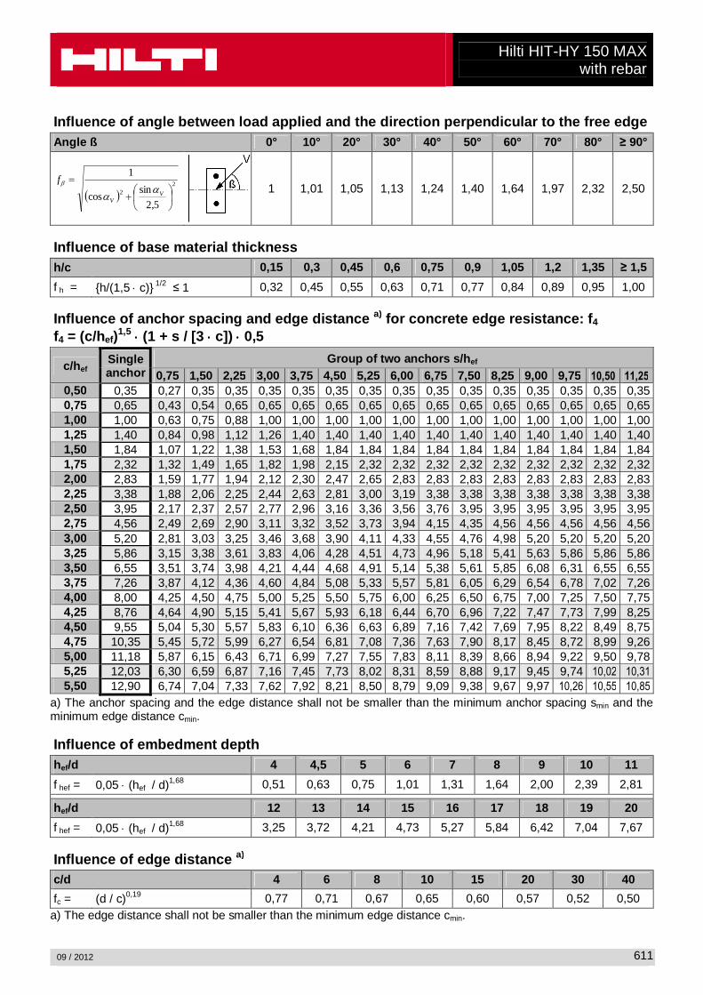
Influence of angle between load applied and the dir ection perpendicular to the free edge
Angle ß 0° 10° 20° 30° 40° 50° 60° 70° 80° ≥ 90°
( )2
2
5,2
sincos
1
+
=V
V
fα
αβ
1 1,01 1,05 1,13 1,24 1,40 1,64 1,97 2,32 2,50
Influence of base material thickness
h/c 0,15 0,3 0,45 0,6 0,75 0,9 1,05 1,2 1,35 ≥ 1,5
f h = {h/(1,5 ⋅ c)} 1/2 ≤ 1 0,32 0,45 0,55 0,63 0,71 0,77 0,84 0,89 0,95 1,00 Influence of anchor spacing and edge distance a) for concrete edge resistance: f 4 f4 = (c/hef)1,5 ⋅⋅⋅⋅ (1 + s / [3 ⋅⋅⋅⋅ c]) ⋅⋅⋅⋅ 0,5
c/h ef Single anchor
Group of two anchors s/h ef 0,75 1,50 2,25 3,00 3,75 4,50 5,25 6,00 6,75 7,50 8,25 9,00 9,75 10,50 11,25
0,50 0,35 0,27 0,35 0,35 0,35 0,35 0,35 0,35 0,35 0,35 0,35 0,35 0,35 0,35 0,35 0,35 0,75 0,65 0,43 0,54 0,65 0,65 0,65 0,65 0,65 0,65 0,65 0,65 0,65 0,65 0,65 0,65 0,65 1,00 1,00 0,63 0,75 0,88 1,00 1,00 1,00 1,00 1,00 1,00 1,00 1,00 1,00 1,00 1,00 1,00 1,25 1,40 0,84 0,98 1,12 1,26 1,40 1,40 1,40 1,40 1,40 1,40 1,40 1,40 1,40 1,40 1,40 1,50 1,84 1,07 1,22 1,38 1,53 1,68 1,84 1,84 1,84 1,84 1,84 1,84 1,84 1,84 1,84 1,84 1,75 2,32 1,32 1,49 1,65 1,82 1,98 2,15 2,32 2,32 2,32 2,32 2,32 2,32 2,32 2,32 2,32 2,00 2,83 1,59 1,77 1,94 2,12 2,30 2,47 2,65 2,83 2,83 2,83 2,83 2,83 2,83 2,83 2,83 2,25 3,38 1,88 2,06 2,25 2,44 2,63 2,81 3,00 3,19 3,38 3,38 3,38 3,38 3,38 3,38 3,38 2,50 3,95 2,17 2,37 2,57 2,77 2,96 3,16 3,36 3,56 3,76 3,95 3,95 3,95 3,95 3,95 3,95 2,75 4,56 2,49 2,69 2,90 3,11 3,32 3,52 3,73 3,94 4,15 4,35 4,56 4,56 4,56 4,56 4,56 3,00 5,20 2,81 3,03 3,25 3,46 3,68 3,90 4,11 4,33 4,55 4,76 4,98 5,20 5,20 5,20 5,20 3,25 5,86 3,15 3,38 3,61 3,83 4,06 4,28 4,51 4,73 4,96 5,18 5,41 5,63 5,86 5,86 5,86 3,50 6,55 3,51 3,74 3,98 4,21 4,44 4,68 4,91 5,14 5,38 5,61 5,85 6,08 6,31 6,55 6,55 3,75 7,26 3,87 4,12 4,36 4,60 4,84 5,08 5,33 5,57 5,81 6,05 6,29 6,54 6,78 7,02 7,26 4,00 8,00 4,25 4,50 4,75 5,00 5,25 5,50 5,75 6,00 6,25 6,50 6,75 7,00 7,25 7,50 7,75 4,25 8,76 4,64 4,90 5,15 5,41 5,67 5,93 6,18 6,44 6,70 6,96 7,22 7,47 7,73 7,99 8,25 4,50 9,55 5,04 5,30 5,57 5,83 6,10 6,36 6,63 6,89 7,16 7,42 7,69 7,95 8,22 8,49 8,75 4,75 10,35 5,45 5,72 5,99 6,27 6,54 6,81 7,08 7,36 7,63 7,90 8,17 8,45 8,72 8,99 9,26 5,00 11,18 5,87 6,15 6,43 6,71 6,99 7,27 7,55 7,83 8,11 8,39 8,66 8,94 9,22 9,50 9,78 5,25 12,03 6,30 6,59 6,87 7,16 7,45 7,73 8,02 8,31 8,59 8,88 9,17 9,45 9,74 10,02 10,31
5,50 12,90 6,74 7,04 7,33 7,62 7,92 8,21 8,50 8,79 9,09 9,38 9,67 9,97 10,26 10,55 10,85
a) The anchor spacing and the edge distance shall not be smaller than the minimum anchor spacing smin and the minimum edge distance cmin. Influence of embedment depth
hef/d 4 4,5 5 6 7 8 9 10 11
f hef = 0,05 ⋅ (hef / d)1,68 0,51 0,63 0,75 1,01 1,31 1,64 2,00 2,39 2,81 hef/d 12 13 14 15 16 17 18 19 20
f hef = 0,05 ⋅ (hef / d)1,68 3,25 3,72 4,21 4,73 5,27 5,84 6,42 7,04 7,67 Influence of edge distance a)
c/d 4 6 8 10 15 20 30 40
fc = (d / c)0,19 0,77 0,71 0,67 0,65 0,60 0,57 0,52 0,50 a) The edge distance shall not be smaller than the minimum edge distance cmin.
Hilti HIT-HY 150 MAX with rebar
09 / 2012
612
Combined TENSION and SHEAR loading For combined tension and shear loading see section “Anchor Design”. Precalculated values – design resistance values All data applies to: - non-cracked concrete C 20/25 – fck,cube =25 N/mm² - temperature range I (see service temperature range) - minimum thickness of base material - no effects of dense reinforcement Recommended loads can be calculated by dividing the design resistance by an overall partial safety factor for action γ = 1,4. The partial safety factors for action depend on the type of loading and shall be taken from national regulations.

Hilti HIT-HY 150 MAX with rebar
09 / 2012
613
Design resistance: concrete C 20/25 - minimum embedment depth
Anchor size Ø8 Ø10 Ø12 Ø14 Ø16 Ø20 Ø25
Embedment depth hef = hef,min [mm] 60 60 70 80 90 100 110
Base material thickness h = hmin [mm] 100 100 102 116 130 150 174
Tensile N Rd: single anchor, no edge effects Non-cracked concrete
BSt 500 S [kN] 8,0 9,9 13,9 18,6 28,7 33,7 32,4
Cracked concrete
BSt 500 S [kN] - 6,9 9,7 14,1 18,1 24,0 23,1
Shear VRd: single anchor, no edge effects, without lever arm Non-cracked concrete
BSt 500 S [kN] 9,3 14,7 20,7 28,0 36,7 57,3 64,7
Cracked concrete
BSt 500 S [kN] - 13,8 19,4 28,0 36,2 48,0 46,1 Design resistance: concrete C 20/25 - minimum embedment depth
Anchor size Ø8 Ø10 Ø12 Ø14 Ø16 Ø20 Ø25
Embedment depth hef = hef,min [mm] 60 60 70 80 90 100 110
Base material thickness h = hmin [mm] 100 100 102 116 130 150 174
Edge distance c = cmin [mm] 40 50 60 80 100 120 135
Tensile N Rd: single anchor, min. edge distance (c = c min ) Non-cracked concrete
BSt 500 S [kN] 4,8 6,7 9,5 12,8 19,4 24,4 25,0
Cracked concrete
BSt 500 S [kN] - 4,7 6,6 10,6 14,5 20,3 19,8
Shear VRd: single anchor, min. edge distance (c = c min ), without lever arm Non-cracked concrete
BSt 500 S [kN] 3,5 4,9 6,6 10,0 13,2 17,4 21,8
Cracked concrete
BSt 500 S [kN] - 3,5 4,7 7,1 9,4 12,3 15,4 Design resistance: concrete C 20/25 - minimum embedment depth (load values are valid for single anchor)
Anchor size Ø8 Ø10 Ø12 Ø14 Ø16 Ø20 Ø25
Embedment depth hef = hef,min [mm] 60 60 70 80 90 100 110
Base material thickness h = hmin [mm] 100 100 100 116 138 156 170
Spacing s = smin [mm] 40 50 60 80 100 120 135
Tensile N Rd: double anchor, no edge effects, min. spacing (s = smin ) Non-cracked concrete
BSt 500 S [kN] 5,4 6,8 9,3 12,2 17,6 21,3 22,5
Cracked concrete
BSt 500 S [kN] - 4,9 6,7 9,5 12,1 15,2 16,0
Shear VRd: double anchor, no edge effects, min. spacing (s = smin ), without lever arm Non-cracked concrete
BSt 500 S [kN] 9,3 12,7 17,9 24,0 36,7 44,9 47,1
Cracked concrete
BSt 500 S [kN] - 8,8 12,4 18,2 23,5 32,0 33,6
Hilti HIT-HY 150 MAX with rebar
09 / 2012
614
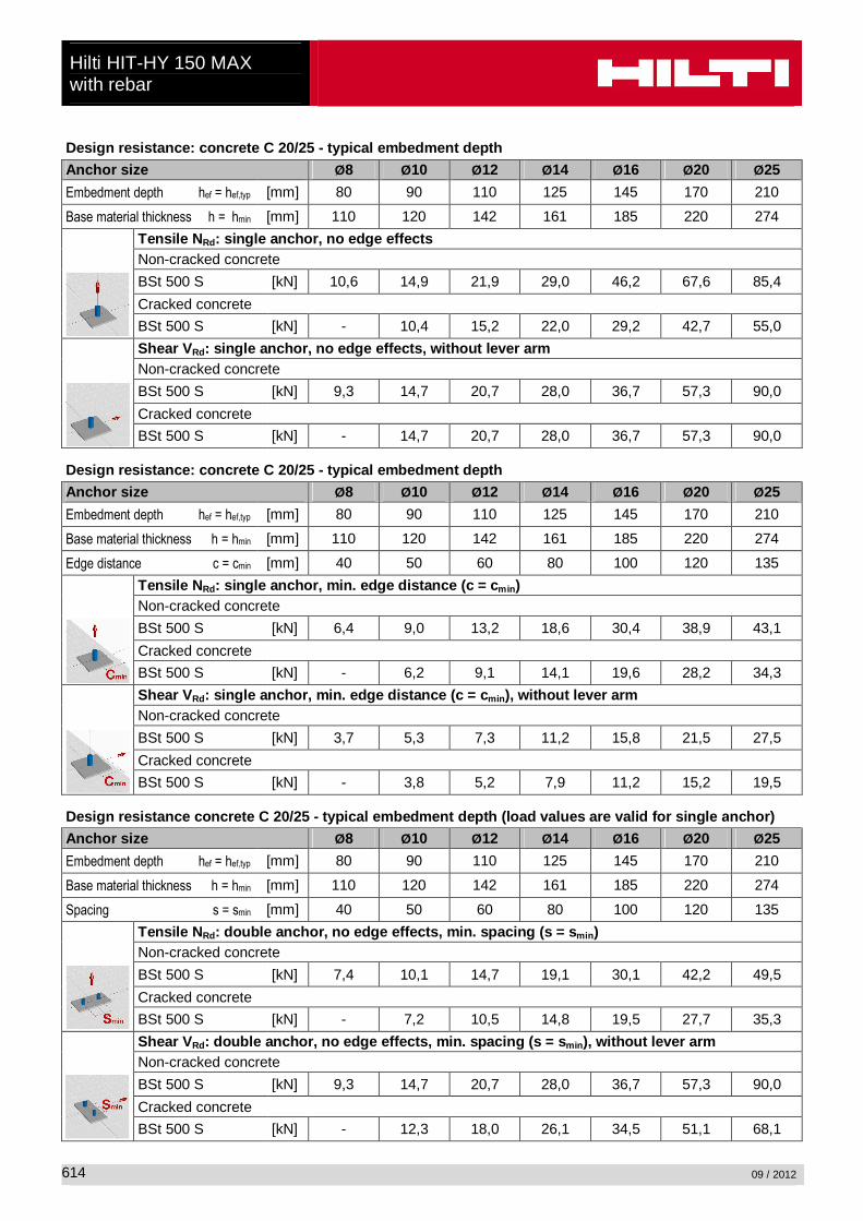
Design resistance: concrete C 20/25 - typical embedment depth
Anchor size Ø8 Ø10 Ø12 Ø14 Ø16 Ø20 Ø25
Embedment depth hef = hef,typ [mm] 80 90 110 125 145 170 210
Base material thickness h = hmin [mm] 110 120 142 161 185 220 274
Tensile N Rd: single anchor, no edge effects Non-cracked concrete
BSt 500 S [kN] 10,6 14,9 21,9 29,0 46,2 67,6 85,4
Cracked concrete
BSt 500 S [kN] - 10,4 15,2 22,0 29,2 42,7 55,0
Shear VRd: single anchor, no edge effects, without lever arm Non-cracked concrete
BSt 500 S [kN] 9,3 14,7 20,7 28,0 36,7 57,3 90,0
Cracked concrete
BSt 500 S [kN] - 14,7 20,7 28,0 36,7 57,3 90,0 Design resistance: concrete C 20/25 - typical embedment depth
Anchor size Ø8 Ø10 Ø12 Ø14 Ø16 Ø20 Ø25
Embedment depth hef = hef,typ [mm] 80 90 110 125 145 170 210
Base material thickness h = hmin [mm] 110 120 142 161 185 220 274
Edge distance c = cmin [mm] 40 50 60 80 100 120 135
Tensile N Rd: single anchor, min. edge distance (c = c min ) Non-cracked concrete
BSt 500 S [kN] 6,4 9,0 13,2 18,6 30,4 38,9 43,1
Cracked concrete
BSt 500 S [kN] - 6,2 9,1 14,1 19,6 28,2 34,3
Shear VRd: single anchor, min. edge distance (c = c min ), without lever arm Non-cracked concrete
BSt 500 S [kN] 3,7 5,3 7,3 11,2 15,8 21,5 27,5
Cracked concrete
BSt 500 S [kN] - 3,8 5,2 7,9 11,2 15,2 19,5 Design resistance concrete C 20/25 - typical embedment depth (load values are valid for single a nchor)
Anchor size Ø8 Ø10 Ø12 Ø14 Ø16 Ø20 Ø25
Embedment depth hef = hef,typ [mm] 80 90 110 125 145 170 210
Base material thickness h = hmin [mm] 110 120 142 161 185 220 274
Spacing s = smin [mm] 40 50 60 80 100 120 135
Tensile N Rd: double anchor, no edge effects, min. spacing (s = smin ) Non-cracked concrete
BSt 500 S [kN] 7,4 10,1 14,7 19,1 30,1 42,2 49,5
Cracked concrete
BSt 500 S [kN] - 7,2 10,5 14,8 19,5 27,7 35,3
Shear VRd: double anchor, no edge effects, min. spacing (s = smin ), without lever arm Non-cracked concrete
BSt 500 S [kN] 9,3 14,7 20,7 28,0 36,7 57,3 90,0
Cracked concrete
BSt 500 S [kN] - 12,3 18,0 26,1 34,5 51,1 68,1
Hilti HIT-HY 150 MAX with rebar
09 / 2012
615
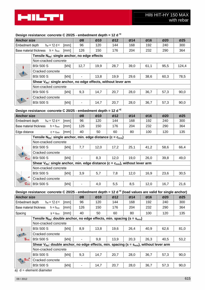
Design resistance: concrete C 20/25 - embedment depth = 12 d a)
Anchor size Ø8 Ø10 Ø12 Ø14 Ø16 Ø20 Ø25 Embedment depth hef = 12 d a) [mm] 96 120 144 168 192 240 300
Base material thickness h = hmin [mm] 126 150 176 204 232 290 364
Tensile N Rd: single anchor, no edge effects Non-cracked concrete
BSt 500 S [kN] 12,7 19,9 28,7 39,0 61,1 95,5 124,4
Cracked concrete
BSt 500 S [kN] - 13,8 19,9 29,6 38,6 60,3 78,5
Shear VRd: single anchor, no edge effects, without lever arm Non-cracked concrete
BSt 500 S [kN] 9,3 14,7 20,7 28,0 36,7 57,3 90,0
Cracked concrete
BSt 500 S [kN] - 14,7 20,7 28,0 36,7 57,3 90,0 Design resistance: concrete C 20/25 - embedment depth = 12 d a) Anchor size Ø8 Ø10 Ø12 Ø14 Ø16 Ø20 Ø25 Embedment depth hef = 12 d a) [mm] 96 120 144 168 192 240 300
Base material thickness h = hmin [mm] 126 150 176 204 232 290 364
Edge distance c = cmin [mm] 40 50 60 80 100 120 135
Tensile N Rd: single anchor, min. edge distance (c = c min ) Non-cracked concrete
BSt 500 S [kN] 7,7 12,0 17,2 25,1 41,2 58,6 66,4
Cracked concrete
BSt 500 S [kN] - 8,3 12,0 19,0 26,0 39,8 49,0
Shear VRd: single anchor, min. edge distance (c = c min ), without lever arm Non-cracked concrete
BSt 500 S [kN] 3,9 5,7 7,8 12,0 16,9 23,6 30,5
Cracked concrete
BSt 500 S [kN] - 4,0 5,5 8,5 12,0 16,7 21,6 Design resistance: concrete C 20/25 - embedment depth = 12 d a) (load values are valid for single anchor) Anchor size Ø8 Ø10 Ø12 Ø14 Ø16 Ø20 Ø25 Embedment depth hef = 12 d a) [mm] 96 120 144 168 192 240 300
Base material thickness h = hmin [mm] 126 150 176 204 232 290 364
Spacing s = smin [mm] 40 50 60 80 100 120 135
Tensile N Rd: double anchor, no edge effects, min. spacing (s = smin ) Non-cracked concrete
BSt 500 S [kN] 8,9 13,8 19,6 26,4 40,9 62,6 81,0
Cracked concrete
BSt 500 S [kN] - 9,8 13,9 20,3 26,3 40,5 53,2
Shear VRd: double anchor, no edge effects, min. spacing (s = smin ), without lever arm Non-cracked concrete
BSt 500 S [kN] 9,3 14,7 20,7 28,0 36,7 57,3 90,0
Cracked concrete
BSt 500 S [kN] - 14,7 20,7 28,0 36,7 57,3 90,0 a) d = element diameter
REV. 02/02/16
Henry Company 999 N. Sepulveda, Ste 800, El Segundo CA 90245-2754
Technical Services- Phone (800) 486-1278 – Email: [email protected]
TECHNICAL DATA SHEET
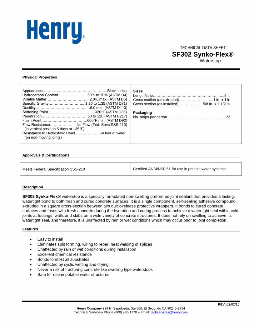
SF302 Synko-Flex® Waterstop
Physical Properties
Appearance…………………………………………….Black strips Hydrocarbon Content…………………. 50% to 70% (ASTM D4) Volatile Matter……………………………..2.0% max. (ASTM D6) Specific Gravity………………………...1.20 to 1.35 (ASTM D71) Ductility…………………………………..…5.0 min. (ASTM D113) Softening Point……………………………..…320°F (ASTM D36) Penetration……………………………….50 to 120 (ASTM D217) Flash Point……………………………….600°F min. (ASTM D92) Flow Resistance………………....No Flow (Fed. Spec SSS-210) (in vertical position 5 days at 135°F) Resistance to Hydrostatic Head………………..68 feet of water (on non-moving joints)
Sizes Length/strip……………………………………………..…..3 ft. Cross section (as extruded)……………………....1 in. x 1 in. Cross section (as installed)……………..…5/8 in. x 1-1/2 in.
Packaging No. strips per carton…………………………………..…….35
Approvals & Certifications
Meets Federal Specification SSS-210
Certified ANSI/NSF 61 for use in potable water systems
Description
SF302 Synko-Flex® waterstop is a specially formulated non-swelling preformed joint sealant that provides a lasting, watertight bond to both fresh and cured concrete surfaces. It is a single component, self-sealing adhesive compound, extruded in a square cross-section between two quick-release protective wrappers. It bonds to cured concrete surfaces and fuses with fresh concrete during the hydration and curing process to achieve a watertight seal within cold joints at footings, walls and slabs on a wide variety of concrete structures. It does not rely on swelling to achieve its watertight seal, and therefore, it is unaffected by rain or wet conditions which may occur prior to joint completion.
Features
Easy to install
Eliminates split forming, wiring to rebar, heat welding of splices
Unaffected by rain or wet conditions during installation
Excellent chemical resistance
Bonds to most all substrates
Unaffected by cyclic wetting and drying
Never a risk of fracturing concrete like swelling type waterstops
Safe for use in potable water structures
REV. 02/02/16
Henry Company 999 N. Sepulveda, Ste 800, El Segundo CA 90245-2754
Technical Services- Phone (800) 486-1278 – Email: [email protected]
SF302 Synko-Flex®
Uses
SF302 Synko-Flex® is designed to provide a watertight seal of cold joints in a wide range of concrete structures including: residential and commercial basements, secondary containment structures, highway tunnels, concrete lined storm drainage and irrigation channels, pedestrian tunnels and below-grade walkways, swimming pools and water features, below-grade parking garages, waste-water treatment plants, fish hatcheries and aquariums, potable water reservoirs, and water theme
parks. SF302 Synko-Flex® may also be used to seal around concrete, steel, PVC, or HDPE pipe penetrations through
concrete walls or floor slabs. SF302 Synko-Flex® is also ideal for use as a joint sealant on precast structures such as box culverts, septic tanks and utility vaults.
Surface Preparation
Joint surfaces should be clean and dry before priming and just prior to placing the SF302 Synko-Flex® strips. Concrete should cure a minimum of 24 hours prior to priming. Ensure that concrete surfaces are free from form oils, release agents, curing compounds, laitance and other dirt or debris. Use a wire brush or stiff bristle brush to clean surface prior to priming.
Application
Positioning: SF302 Synko-Flex® is generally positioned in the center of the joint. It may be placed at the bottom of a keyway, if a keyway is incorporated into the joint design. However, a keyway is not required for the use of this product. Two inches of concrete coverage is recommended.
Standard Method: Apply primer to the cured surface and allow to dry. Drying time generally takes 2 to 3 hours. Drying time will take longer in low temperatures and in humid environments.
Peel the protective release paper from one side of the Synko-Flex® strip. Place the strip onto the primed surface pressing firmly along the entire length of the strip. The strip should be depressed to approximately 5/8 inch in thickness forcing it to widen to approximately 1-1/2 inches. Splice strips together with a 1-inch overlap or side lap.
Remove the remaining release film. Fresh concrete may then be poured directly against the Synko-Flex®. The waterstop sealing system is complete when the fresh concrete cures.
In cold weather, both the Synko-Flex® strips and the concrete surface should be warmed just prior to application.
Alternate Application Method: Synko-Flex® may also be installed directly in the fresh concrete.
Horizontal Applications: Peel the protective release paper from one side of the Synko-Flex® strip. While concrete is still
wet, carefully press the Synko-Flex® strips into the fresh concrete, leaving approximately ½ inch exposed above the concrete surface. When concrete cures, remove remaining release film, and continue with pour.
Vertical Applications: Peel off release paper from one side of the strip, leaving the polyethylene release film on the
formwork side of the Synko-Flex® to prevent the Synko-Flex® from adhering to the formwork and to keep the
Synko-Flex® clean once the forms are removed. The Synko-Flex® is then nailed to the inside of the concrete form using
small finishing nails. Chamfer strips (1/2”) should be positioned on each side of the Synko-Flex® strip. Finishing nails will
pull through the Synko-Flex® strips when end form is removed.
Limitations: Synko-Flex® is designed for use in non-moving or reinforced joints. Contact manufacturer regarding applications where limited movement could be expected.
REV. 02/02/16
Henry Company 999 N. Sepulveda, Ste 800, El Segundo CA 90245-2754
Technical Services- Phone (800) 486-1278 – Email: [email protected]
SF302 Synko-Flex
®
Caution
WARNING. Causes skin irritation. Causes serious eye irritation. May cause respiratory irritation.
Prevention: Wash thoroughly after handling. Avoid breathing mists and sprays. Use only outdoors or in a well-ventilated area. Wear protective gloves and eye protection.
Response: IF ON SKIN: Wash with plenty of soap and water. If skin irritation occurs; Get medical advice or attention. Take off contaminated clothing and wash it before reuse. IF IN EYES: Rinse cautiously with water for several minutes. Remove contact lenses, if present and easy to do. Continue rinsing. If eye irritation persists; Get medical advice or attention. IF INHALED: Remove person to fresh air and keep comfortable for breathing. Call a POISON CENTER or doctor if you feel unwell.
Storage: Store in a well-ventilated place. Store locked up.
Disposal: Dispose of contents/containers in accordance with local/regional/national/international regulations. See safety data sheet for further details regarding the safe use of this product.
KEEP OUT OF REACH OF CHILDREN.
This product contains chemicals known to the State of California to cause cancer and/or birth defects or other reproductive harm.
LIMITED PRODUCT WARRANTY AND LIABILITY DISCLAIMER
We, the manufacturer, warrant only that this product is free of defects, since many factors which affect the results obtained from this product- such as weather, workmanship, equipment utilized and prior condition of the substrate - are all beyond our control. We will replace at no charge any product proved to have a material defect within12-months of purchase, provided it has been applied in accordance with our written directions for uses we recommend as suitable for this product. Proof of purchase must be provided. DISCLAIMER OF WARRANTIES AND LIMITATION OF LIABILITY: THIS LIMITED WARRANTY IS IN LIEU OF ANY OTHER WARRANTIES EXPRESS OR IMPLIED INCLUDING BUT NOT LIMITED TO ANY IMPLIED WARRANTY OF MERCHANTABILITY OR FITNESS FOR A PARTICULAR PURPOSE. MANUFACTURER SHALL HAVE NO LIABILITY OF ANY KIND BEYOND PRODUCT REPLACEMENT, INCLUDING FOR CONSEQUENTIAL OR INCIDENTAL DAMAGES RESULTING FROM ANY DEFECTS OR ANY DELAYS CAUSED BY REPLACEMENT OR OTHERWISE. IF PURCHASER DOES NOT ACCEPT THESE TERMS OF HENRY'S LIMITED WARRANTY, PURCHASER MAY RETURN ALL CONTAINERS OR PACKAGES OF PRODUCT PURCHASED FOR A FULL REFUND (PROVIDED THE CONTAINERS OR PACKAGING IS UNOPENED AND LESS SHIPPING CHARGES IF ANY) WITHIN 30-DAYS OF PURCHASE. RETENTION OF PRODUCT BEYOND 30-DAYS FROM PURCHASE, OR USE OF PRODUCT SHALL CONSTITUTE ACCEPTANCE OF HENRY'S LIMITED WARRANTY TERMS, CONDITIONS AND DISCLAIMERS. THIS LIMITED WARRANTY PROVIDES THE PURCHASER'S EXCLUSIVE REMEDY FOR ANY DEFECT IN THE PRODUCT. For further details of Henry's product warranty, see our website at www.henry.com/warranty.
Statement of Responsibility
The technical and application information herein is based on the present state of our best scientific and practical knowledge. As the information herein is of a general nature, no assumption can be made as to a product’s suitability for a particular use or application and no warranty as to its accuracy, reliability or completeness either expressed or implied is given other than those required by law. The user is responsible for checking the suitability of products for their intended use. Henry Company data sheets are updated on a regular basis; it is the user’s responsibility to obtain and to confirm the most recent version. Information contained in this data sheet may change without notice.
Waterproo
fing
PRIOR TO EACH USE OF ANY SIKA PRODUCT, THE USER MUST ALWAYS READ AND FOLLOW THE WARNINGS AND INSTRUCTIONS ON THE PRODUCT’S MOST CURRENT PRODUCT DATA SHEET, PRODUCT LABEL AND SAFETY DATA SHEET WHICH ARE AVAILABLE ONLINE AT HTTP://USA.SIKA.COM/ OR BY CALLING SIKA’S TECHNICAL SERVICE DEPARTMENT AT 800-933-7452. NOTHING CONTAINED IN ANY SIKA MATERIALS RELIEVES THE USER OF THE OBLIGATION TO READ AND FOLLOW THE WARNINGS AND INSTRUCTION FOR EACH SIKA PRODUCT AS SET FORTH IN THE CURRENT PRODUCT DATA SHEET, PRODUCT LABEL AND SAFETY DATA SHEET PRIOR TO PRODUCT USE.
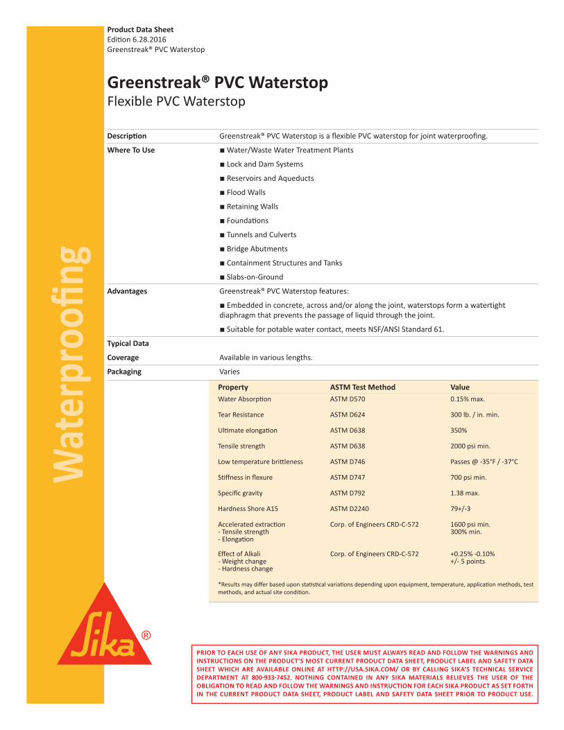
Property ASTM Test Method ValueWater Absorption ASTM D570 0.15% max.
Tear Resistance ASTM D624 300 lb. / in. min.
Ultimate elongation ASTM D638 350%
Tensile strength ASTM D638 2000 psi min.
Low temperature brittleness ASTM D746 Passes @ -35°F / -37°C
Stiffness in flexure ASTM D747 700 psi min.
Specific gravity ASTM D792 1.38 max.
Hardness Shore A15 ASTM D2240 79+/-3
Accelerated extraction Corp. of Engineers CRD-C-572 1600 psi min. - Tensile strength 300% min.- Elongation Effect of Alkali Corp. of Engineers CRD-C-572 +0.25% -0.10%- Weight change +/- 5 points- Hardness change
*Results may differ based upon statistical variations depending upon equipment, temperature, application methods, testmethods, and actual site condition.
Greenstreak® PVC WaterstopFlexible PVC Waterstop
Description Greenstreak® PVC Waterstop is a flexible PVC waterstop for joint waterproofing.
Where To Use • Water/Waste Water Treatment Plants
• Lock and Dam Systems
• Reservoirs and Aqueducts
• Flood Walls
• Retaining Walls
• Foundations
• Tunnels and Culverts
• Bridge Abutments
• Containment Structures and Tanks
• Slabs-on-Ground
Advantages Greenstreak® PVC Waterstop features:
• Embedded in concrete, across and/or along the joint, waterstops form a watertight diaphragm that prevents the passage of liquid through the joint.
• Suitable for potable water contact, meets NSF/ANSI Standard 61.
Typical Data
Coverage Available in various lengths.
Packaging Varies
Product Data SheetEdition 6.28.2016Greenstreak® PVC Waterstop
Wat
erpr
oofin
g
KEEP CONTAINER TIGHTLY CLOSED • KEEP OUT OF REACH OF CHILDREN • NOT FOR INTERNAL CONSUMPTION • FOR INDUSTRIAL USE ONLY • FOR PROFESSIONAL USE ONLY
All information provided by Sika Corporation (“Sika”) concerning Sika products, including but not limited to, any recommendations and ad-vice relating to the application and use of Sika products, is given in good faith based on Sika’s current experience and knowledge of its prod-ucts when properly stored, handled and applied under normal conditions in accordance with Sika’s instructions. In practice, the differences in materials, substrates, storage and handling conditions, actual site conditions and other factors outside of Sika’s control are such that Sika assumes no liability for the provision of such information, advice, recommendations or instructions related to its products, nor shall any le-gal relationship be created by or arise from the provision of such information, advice, recommendations or instructions related to its prod-ucts. The user of the Sika product(s) must test the product(s) for suitability for the intended application and purpose before proceeding with the full application of the product(s). Sika reserves the right to change the properties of its products without notice. All sales of Sika product(s) are subject to its current terms and conditions of sale which are available at http://usa.sika.com/ or by calling 800-933-7452.
Sika warrants this product for one year from date of installation to be free from manufacturing defects and to meet the technical proper-ties on the current Product Data Sheet if used as directed within shelf life. User determines suitability of product for intended use and as-sumes all risks. Buyer’s sole remedy shall be limited to the purchase price or replacement of product exclusive of labor or cost of labor.
NO OTHER WARRANTIES EXPRESS OR IMPLIED SHALL APPLY INCLUDING ANY WARRANTY OF MERCHANTABILITY OR FITNESS FOR A PARTICULAR PURPOSE. SIKA SHALL NOT BE LIABLE UNDER ANY LEGAL THEORY FOR SPECIAL OR CONSEQUENTIAL DAMAGES. SIKA SHALL NOT BE RESPONSIBLE FOR THE USE OF THIS PRODUCT IN A MANNER TO INFRINGE ON ANY PATENT OR ANY OTHER INTELLECTUAL PROPERTY RIGHTS HELD BY OTHERS.
Sika Corporation201 Polito AvenueLyndhurst, NJ 07071Phone: (201) 933-8800Fax: (201) 933-6225usa.sika.com
Sika Greenstreak Sales Office3400 Tree Court Industrial Blvd.St. Louis, MO 63122Tel: (636) 225-9400Fax: (636) 225-2049usa.sika.com
Sika Canada Inc.601, Delmar AvenuePointe-Claire, QC H9R 4A9Phone: (514) 697-2610Fax: (514) 697-3087can.sika.com
PRIOR TO EACH USE OF ANY SIKA PRODUCT, THE USER MUST ALWAYS READ AND FOLLOW THE WARNINGS AND INSTRUCTIONS ON THE PRODUCT’S MOST CURRENT PRODUCT DATA SHEET, PRODUCT LABEL AND SAFETY DATA SHEET WHICH ARE AVAILABLE ONLINE AT HTTP://USA.SIKA.COM/ OR BY CALLING SIKA’S TECHNICAL SERVICE DEPARTMENT AT 800-933-7452. NOTHING CONTAINED IN ANY SIKA MATERIALS RELIEVES THE USER OF THE OBLIGATION TO READ AND FOLLOW THE WARNINGS AND INSTRUCTION FOR EACH SIKA PRODUCT AS SET FORTH IN THE CURRENT PRODUCT DATA SHEET, PRODUCT LABEL AND SAFETY DATA SHEET PRIOR TO PRODUCT USE.
How to Use
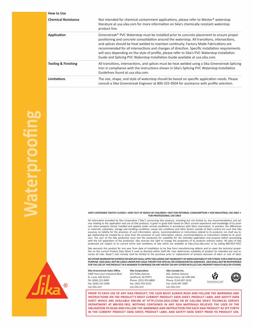
Chemical Resistance Not intended for chemical containment applications, please refer to Westec® waterstop literature at usa.sika.com for more information on Sika’s chemically resistant waterstop product line.
Application Greenstreak® PVC Waterstop must be installed prior to concrete placement to ensure proper positioning and concrete consolidation around the waterstop. All transitions, intersections, and splices should be heat welded to maintain continuity. Factory Made Fabrications are recommended for all intersections and changes of direction. Specific installation requirements will vary depending on the style of profile, please refer to Sika’s PVC Waterstop Installation Guide and Splicing PVC Waterstop Installation Guide available at usa.sika.com.
Tooling & Finishing All transitions, intersections, and splices must be heat welded using a Sika Greenstreak Splicing Iron in compliance with the instructions shown in Sika’s Splicing PVC Waterstop Installation Guidelines found at usa.sika.com.
Limitations The size, shape, and style of waterstop should be based on specific application needs. Please consult a Sika Greenstreak Engineer at 800-325-9504 for assistance with profile selection.
DESCRIPTIONA water-based, liquid membrane forming, resin curingcompound for freshly finished concrete. The WhiteResin Cure J10W is white pigmented to reflect the heatof the sun.
USEWhite Resin Cure J10W is a curing compoundformulated to retain moisture in freshly finishedconcrete to insure full hydration of the cement.Specifically designed for use on exterior commercialprojects such as highway pavements, residential paving,airport runways, parking lots and other pavementprojects.
FEATURES■ Water-based■ Meets ASTM and AASHTO Standards■ Approved by numerous state highway departments■ Clean-Up with Water■ White pigments to reflect the heat of the sun
PROPERTIESASTM C-309 Type 2, Classes A & BAASHTO M-148 Type 2, Classes A & B
Drying time:Approximately 2 hrs. at 70° F (21°C)
VOCLess than 350 g/l. Complies with Canadian and U.S.Federal EPA ,OTC, LADCO & CARB Standards forConcrete Curing Compounds
For areas in California governed by SCAQMD thisproduct can be used FOR ROADWAYS AND BRIDGESONLY (Not for Use on Curbs and Gutters, Sidewalks,Islands, Driveways and Other Miscellaneous ConcreteAreas)
Estimating GuideCoverage: 200 sq. ft./gal. (4.9 sq. M/L)
Packaging
PRODUCTCODE PACKAGE
SIZE
Gallons Liters
69104 Pail 5 18.93
69103 Drum 55 208.20
STORAGEThe White Resin Cure J10W should be stored in tightlysealed original factory containers. Store in a horizontalposition to prevent moisture accumulation on the drumhead. Do not allow to freeze. Shelf life of properlystored, unopened containers is 18 months
Mixing:White Resin Cure J10W should be thoroughly stirred priorto each days use. Do not over agitate or use high speedmixing equipment.
Placement:Apply immediately after all surface water has disappearedand the surface cannot be marred. Do not delay inapplying the curing compound. Use low pressure spray,roller or brush. For best results, a spray application is thepreferred method. All application equipment and toolsshould be thoroughly cleaned prior to use to avoidcontamination. Do not thin. Apply uniformly withoutpuddling. Do not interchange spray equipment that hasbeen used with solvent-based curing compounds withspray equipment that has been used with water-basedcuring compounds without thorough cleaning.
CLEAN UPTools and Equipment: While wet use water. After theproduct dries, Dayton Superior Citrus Cleaner J48 ororganic solvents such as xylene may be necessary toremove the product.
LIMITATIONS
FOR PROFESSIONAL USE ONLYThe White Resin Cure J10W should be thoroughly stirredprior to each use.Do not apply at temperature below 40°F (4°C). Cool, dampconditions and/or over application may extend drying anddissipation time.If surface is to be painted, sealed, topped, or otherwisetreated after application, residual membrane should beremoved.
PRECAUTIONS
READ SDS PRIOR TO USING PRODUCT■ Use with adequate ventilation■ Wear protective clothing, gloves and eye protection
(goggles, safety glasses and/or face shield)■ Keep out of the reach of children■ Do not take internally■ In case of ingestion, seek medical help immediately■ May cause skin irritation upon contact, especially
prolonged or repeated. If skin contact occurs, washimmediately with soap and water and seek medicalhelp as needed.
■ If eye contact occurs, flush immediately with cleanwater and seek medical help as needed
■ Dispose of waste material in accordance with federal,state and local requirements
Cur
ing
Com
poun
ds
Sec5
White Resin Cure J10WConcrete Curing Compound
TECHNICAL DATA SHEET
Visit www.daytonsuperior.com for the most up to date technical information
Page 1 of 2 File Date: 1/26/2015
MANUFACTURERDayton Superior Corporation1125 Byers RoadMiamisburg, OH 45342Customer Service: 888-977-9600Technical Services: 877-266-7732Website: www.daytonsuperior.com
WARRANTYDayton Superior Corporation ("Dayton") warrants for 12 monthsfrom the date of manufacture or for the duration of the publishedproduct shelf life, whichever is less, that at the time of shipmentby Dayton, the product is free of manufacturing defects andconforms to Dayton’s product properties in force on the date ofacceptance by Dayton of the order. Dayton shall only be liableunder this warranty if the product has been applied, used, andstored in accordance with Dayton’s instructions, especially surfacepreparation and installation, in force on the date of acceptance byDayton of the order. The purchaser must examine the productwhen received and promptly notify Dayton in writing of any non-conformity before the product is used and no later than 30 daysafter such non-conformity is first discovered. If Dayton, in its solediscretion, determines that the product breached the abovewarranty, it will, in its sole discretion, replace the non-conformingproduct, refund the purchase price or issue a credit in the amountof the purchase price. This is the sole and exclusive remedy forbreach of this warranty. Only a Dayton officer is authorized tomodify this warranty. The information in this data sheetsupersedes all other sales information received by the customerduring the sales process. THE FOREGOING WARRANTY SHALL BEEXCLUSIVE AND IN LIEU OF ANY OTHER WARRANTIES, EXPRESS ORIMPLIED, INCLUDING WARRANTIES OF MERCHANTABILITY ANDFITNESS FOR A PARTICULAR PURPOSE, AND ALL OTHERWARRANTIES OTHERWISE ARISING BY OPERATION OF LAW,COURSE OF DEALING, CUSTOM, TRADE OR OTHERWISE.
Dayton shall not be liable in contract or in tort (including,without limitation, negligence, strict liability or otherwise) forloss of sales, revenues or profits; cost of capital or funds;business interruption or cost of downtime, loss of use, damageto or loss of use of other property (real or personal); failure torealize expected savings; frustration of economic or businessexpectations; claims by third parties (other than for bodilyinjury), or economic losses of any kind; or for any special,incidental, indirect, consequential, punitive or exemplarydamages arising in any way out of the performance of, orfailure to perform, its obligations under any contract for saleof product, even if Dayton could foresee or has been advisedof the possibility of such damages. The Parties expressly agreethat these limitations on damages are allocations of riskconstituting, in part, the consideration for this contract, andalso that such limitations shall survive the determination ofany court of competent jurisdiction that any remedy providedin these terms or available at law fails of its essential purpose.
Curing C
ompounds
Sec5
White Resin Cure J10WConcrete Curing Compound
TECHNICAL DATA SHEET
Visit www.daytonsuperior.com for the most up to date technical information
Page 2 of 2 File Date: 1/26/2015
Form 13302 r05/16 12000 E. 47th Ave., #200, Denver, CO 80239 | Phone: 303-288-7873 | Fax: 303-287-8531 | www.hydrogate.com Page 1 of 2
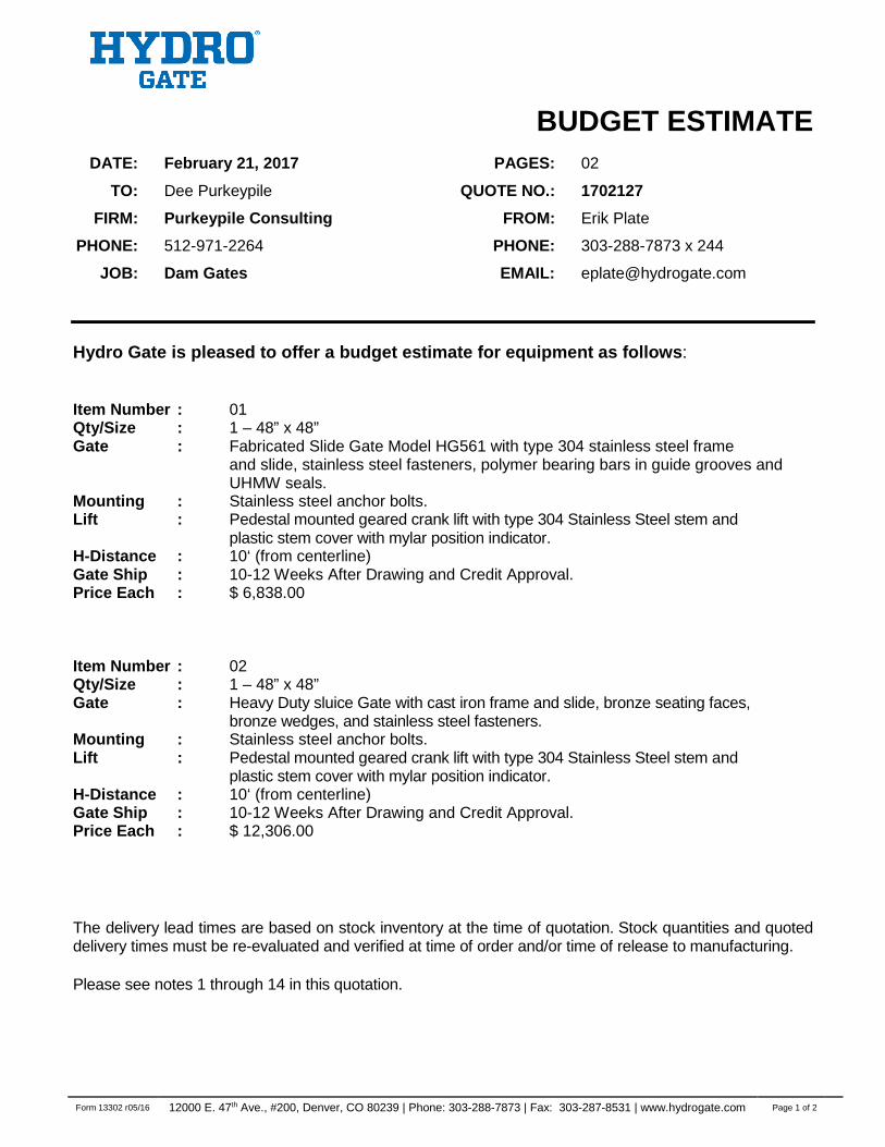
BUDGET ESTIMATE DATE: February 21, 2017 PAGES: 02
TO: Dee Purkeypile QUOTE NO.: 1702127
FIRM: Purkeypile Consulting FROM: Erik Plate
PHONE: 512-971-2264 PHONE: 303-288-7873 x 244
JOB: Dam Gates EMAIL: [email protected]
Hydro Gate is pleased to offer a budget estimate for equipment as follows: Item Number : 01 Qty/Size : 1 – 48” x 48” Gate : Fabricated Slide Gate Model HG561 with type 304 stainless steel frame and slide, stainless steel fasteners, polymer bearing bars in guide grooves and
UHMW seals. Mounting : Stainless steel anchor bolts. Lift : Pedestal mounted geared crank lift with type 304 Stainless Steel stem and plastic stem cover with mylar position indicator. H-Distance : 10‘ (from centerline) Gate Ship : 10-12 Weeks After Drawing and Credit Approval. Price Each : $ 6,838.00 Item Number : 02 Qty/Size : 1 – 48” x 48” Gate : Heavy Duty sluice Gate with cast iron frame and slide, bronze seating faces,
bronze wedges, and stainless steel fasteners. Mounting : Stainless steel anchor bolts. Lift : Pedestal mounted geared crank lift with type 304 Stainless Steel stem and plastic stem cover with mylar position indicator. H-Distance : 10‘ (from centerline) Gate Ship : 10-12 Weeks After Drawing and Credit Approval. Price Each : $ 12,306.00 The delivery lead times are based on stock inventory at the time of quotation. Stock quantities and quoted delivery times must be re-evaluated and verified at time of order and/or time of release to manufacturing. Please see notes 1 through 14 in this quotation.
Form 13302 r05/16 12000 E. 47th Ave., #200, Denver, CO 80239 | Phone: 303-288-7873 | Fax: 303-287-8531 | www.hydrogate.com Page 2 of 2
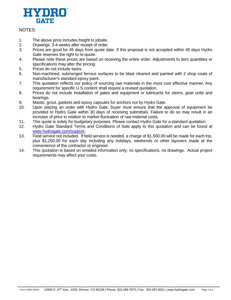
NOTES: 1. The above price includes freight to jobsite. 2. Drawings: 3-4 weeks after receipt of order. 3. Prices are good for 45 days from quote date. If this proposal is not accepted within 45 days Hydro
Gate reserves the right to re-quote. 4. Please note these prices are based on receiving the entire order. Adjustments to item quantities or
specifications may alter the pricing. 5. Prices do not include taxes. 6. Non-machined, submerged ferrous surfaces to be blast cleaned and painted with 2 shop coats of
manufacturer's standard epoxy paint. 7. This quotation reflects our policy of sourcing raw materials in the most cost effective manner. Any
requirement for specific U.S content shall require a revised quotation. 8. Prices do not include installation of gates and equipment or lubricants for stems, gear units and
bearings. 9. Mastic, grout, gaskets and epoxy capsules for anchors not by Hydro Gate. 10. Upon placing an order with Hydro Gate, buyer must ensure that the approval of equipment be
provided to Hydro Gate within 30 days of receiving submittals. Failure to do so may result in an increase of price in relation to market fluctuation of raw material costs.
11. This quote is solely for budgetary purposes. Please contact Hydro Gate for a standard quotation. 12. Hydro Gate Standard Terms and Conditions of Sale apply to this quotation and can be found at
www.hydrogate.com/support. 13. Field service not included. If field service is needed, a charge of $1,500.00 will be made for each trip,
plus $1,250.00 for each day including any holidays, weekends or other layovers made at the convenience of the contractor or engineer.
14. This quotation is based on emailed information only; no specifications, no drawings. Actual project requirements may affect your costs.
PRODUCT SPECIFICATIONS
STAINLESS STEEL SLIDE & WEIR GATE
Form 13718 r2-17 page 1 of 5
GENERAL
SUMMARY
A. The Contractor shall provide all labor, materials, equipment, and incidentals required to furnish and install slide gates, operating stems, and operating floor stands, complete and operational with all necessary accessories as shown on the Contract Drawings, as specified herein, or as required for complete operation.
B. The Contractor shall obtain all equipment specified in this Section from one manufacturer to
ensure proper coordination and functionality. The manufacturer shall have responsibility for performance and compatibility of the entire system. This does in no way relieve the Contractor for ultimate responsibility under this Contract for equipment, coordination, installation, operation and guarantee.
C. The Contract Drawings are for the purpose of guidance and to show functional features and
required external connections. They do not necessarily show all components necessary to accomplish the desired results nor do they necessarily show all components required to interface with the equipment. The Contractor shall provide all parts, equipment, and devices necessary to meet the functional requirements of the system.
REFERENCES
A. Comply with applicable provisions and recommendations of the following, except as
otherwise shown or specified:
1. American Water Works Association (AWWA C561) 2. American National Standards Institute (ANSI) 3. American Society for Testing and Materials (ASTM)
SYSTEM DESCRIPTION
A. Design Requirements:
1. The slide gates shall be manufactured in accordance with the latest version of AWWA
C561, and shall be constructed of stainless steel (ASTM 304L or 316L).
2. Liberal safety factors will be used in the design of all equipment. Working stresses will not exceed the lower value of one half of the yield strength or one fourth of the ultimate strength of the material, whichever is less. The slide gates and appurtenances shall be designed for installation in the structures as shown on the plans.
PRODUCT SPECIFICATIONS
STAINLESS STEEL SLIDE & WEIR GATE
Form 13718 r2-17 page 2 of 5
SUBMITTALS
A. For approval: Submit the following shop drawings for approval:
1. Manufacturer’s information, specifications, and data showing dimensions, materials
of construction, and weight of all major items of equipment.
2. Installation diagrams showing location, arrangement, and size of all fasteners required for the equipment.
3. Setting drawings, templates, and instructions for installation of frames, thimbles, etc.
4. Certification that all components were designed based upon the maximum seating
and unseating heads described herein.
B. Upon completion of installation, submit a digital copy of the Operation and Maintenance Manual for this equipment. A final copy of this manual shall be approved by the Engineer prior to distribution and as a minimum shall contain the following:
1. Operational and maintenance manuals shall include all approved shop drawings
associated with this Section, complete instructions for installation, and parts list for all components.
2. Include a list and frequency of specific maintenance activities.
PRODUCTS
MANUFACTURERS
A. Provide slide gates as manufactured by the following:
1. Henry Pratt Company (Hydro Gate brand). 2. Approved equal.
EQUIPMENT MATERIALS
A. All slide gates shown on the plans and listed in the specifications shall conform in all respects to
the latest version of AWWA C561, with the noted changes and additions: Materials used in construction of slide gates and appurtenances will be best suited for the application and will conform to the following specifications:
1. Frame, Slide, Reinforcing Members and Self-contained Yoke (as required):
Stainless Steel, ASTM A240/A240M, Type 304L or 316L.
2. Stems and retainer bars: Stainless Steel, ASTM A276, Type 304 or 316.
3. Fasteners: Stainless Steel, ASTM F593/F594, Alloy Group 1 or 2 (Type 304 or 316).
PRODUCT SPECIFICATIONS
STAINLESS STEEL SLIDE & WEIR GATE
Form 13718 r2-17 page 3 of 5
4. Invert seals and compression load pad: Neoprene or EPDM, ASTM D2000, 60 Durometer.
5. Side seal: Ultra High Molecular Weight (UHMW) Polymer, ASTM D4020. 6. Top wedges: Stainless Steel, ASTM A351-CF8M, Type 304 or 316 7. Pedestals, Wall Brackets and Stem Guide Brackets: Cast Iron, ASTM A126, Class B or
Stainless Steel, ASTM A276, Type 304 or 316. 8. Stem Guide Bushings: Silicon Bronze, ASTM B584, Alloy 873 or Ultra High Molecular
Weight (UHMW) Polymer, ASTM D4020
B. Gate frame shall be flat back, embedded or channel mount as shown in the “Gate Schedule.” Spigot-back frames are not acceptable. The frame shall be an integral unit of brake form and structural shapes, rigidly assembled to form the waterway openings. Holes shall be provided for mounting on anchor bolts. Seats and seals shall be secured to the frame in a manner to insure they will remain in place, free from distortion or loosening during the life of the gate. Seat contact pressure shall not exceed 600psi at the design head.
C. Gate slide shall conform to the safety factors stated under “General”, but shall, in no case, be
less than ¼ inch thick. Deflection under full head shall be limited to 1/720 of the span. The stem connector clips or stem block pocket shall be welded to the slide. Gates over 24” wide shall have adjustable top wedges in order to prevent deflection in the slide resulting from over closure.
D. Flush Bottom: Slide gates shall incorporate a flush-bottom seal that is mechanically fastened to
the bottom frame invert member. The seal shall be of the materials shown in “Materials of Construction.” Press fit seals are not acceptable.
E. Side Seals: UHMW seals shall be provided as specified in the “Gate Schedule.” Seals shall
be securely fastened to the frame with formed stainless steel retainers and shall be replaceable and adjustable without removing the gate from the installed position. A compression load pad shall be set behind the UHMW seal to allow for a self-adjusting seal system. The face of the UHMW guide that is in contact with the cover bar shall have a machined or extruded groove, in order to create a raised surface on each side, to allow for secondary adjustment of the seal clamp force.
F. Yoke: Self-contained gates shall be provided with a yoke designed to withstand the thrust of the
operator. Yoke deflection shall not exceed 1/360 of the gate width or a maximum of ¼ inch, whichever is less at maximum operating load. The yoke head channels shall be welded to the gate frame. The channels shall be sufficiently spaced to allow removal of the gate slide.
G. The operating stem shall be of a size to safely withstand, without buckling or permanent distortion,
the stresses induced by normal operating forces. In addition, the stem shall be designed to transmit in compression at least 2 times the rated output of the floor stand or bench stand with a 40-pound effort on the crank or handwheel. The threaded portion of the stem will have cold rolled threads of the double lead Acme type. Stainless Steel couplings, threaded and keyed to the stems, will join stems of more than one section. All threaded and keyed couplings of the same
PRODUCT SPECIFICATIONS
STAINLESS STEEL SLIDE & WEIR GATE
Form 13718 r2-17 page 4 of 5
size will be interchangeable. Manually operated, rising stem type gates will be provided with an adjustable stop collar on the stem to prevent over-opening of the gate.
H. Gates 48 inch and wider and having widths greater than twice their height shall be provided with
two operators connected by a tandem shaft for simultaneous operation.
I. Stem guides will be split collar bronze type, mounted on cast iron brackets to allow for installation after the stem is placed. They will be adjustable in two directions and will be spaced at sufficient intervals to adequately support the stem. The inside diameter of the guide shall be 1/8 inch to ¼ inch larger than the outside diameter of the stem. Stem guide spacing will not exceed an L/r ratio of 200.
J. Manually operated lifts shall be handwheel or geared crank type as shown in the “Gate
Schedule.” Lifts shall operate the gate with a maximum pull of 40 lb on the handwheel or crank. Handwheel or crank shall be located approximately 36 in. above grating or walkway. All lifts shall have thrust bearings, bronze lift nuts, and a bronze stop nut to limit the downward travel of the stem and slide. All geared lifts shall have cast or ductile iron housings and cast or fabricated pedestals. All lifts shall be rising stem type if possible. Lifts shall be grease lubricated and regreasable through grease zerks. Oil bath lifts are not acceptable.
K. Motor operated lifts shall be a 460-V, 3-phase, 60-Hz motor with precision reduction gearing
enclosed in weatherproof housing. The operator shall be designed to raise the gate at a rate of approximately 10 to 14 inches/min. Integral controls shall include a control power transformer, reversing controller, torque switches, limit switches, internal atmospheric controls to prevent condensation, open- stop-closed push-buttons, and gate position indicator. Where applicable, the controls shall also include a local-off remote selector switch. Motor reduction helical gear and pinion shall be of heat- treated alloy steel. Final reduction worm shall be of alloy steel and worm gear of machined, high- tensile strength bronze. All gearing shall be proportioned for 100% overload condition. Operator shall have a de-clutch lever and handwheel for manual operation.
L. A clear, polycarbonate plastic stem cover and indicator shall be provided on each slide gate
operator. Stem indication shall be provided to denote gate level. A cast aluminum adaptor shall be used to mount the cover to the lift or operator. The covers shall be capped, vented, and of sufficient length to allow full travel of the gate.
FINISHES
A. The gate manufacturer shall be responsible for shop prime and finish painting of all cast iron
and steel accessories supplied under this contract. All coatings shall conform to VOC Emission Regulations in effect at the manufacturing location and at the project site to allow touch up or recoating to be performed with the same products.
B. Submerged surfaces shall be cleaned to SSPC SP10, dry, and grease-free prior to painting in
conformance with the paint manufacturer’s instructions. Non-submerged surfaces shall be cleaned to SSPC SP6.
C. Stainless steel gates and accessories shall not be painted.
PRODUCT SPECIFICATIONS
STAINLESS STEEL SLIDE & WEIR GATE
Form 13718 r2-17 page 5 of 5
D. All cast iron and steel accessories shall receive a primer and finished coat with a high-solids epoxy
coat or approved equal for potable water use. Primer and finished coats shall be applied in the manufacturer’s shop.
E. Where required by application, the coating shall be approved for contact with drinking water by the
NSF, EPA, or other appropriate governing agencies. Number of coats, mil thickness, and surface preparation shall be in accordance with the paint manufacturer’s recommendations for that application.
F. Coating for all cast iron and steel accessories shall be Ameron Amerlock 400, medium gray color.
SHOP TESTING
The completely assembled gate will be shop inspected for proper seating. Seals shall be adjusted to exclude a 0.004 inch thickness gauge between the seating surfaces. The slide gate shall be shop-operated from the fully open to the fully closed position to verify the assembly is workable.
EXECUTION
INSTALLATION
A. The slide gate equipment and appurtenances shall be installed in accordance with the Installation
Manual furnished by the gate manufacturer. Extreme care should be used in handling, storage, and installation of this equipment to prevent damage or distortion of the equipment and to insure proper performance.
FIELD QUALITY CONTROL
A. Field testing shall be performed after installation of the equipment. The field testing shall
demonstrate the following:
1. The equipment has been properly installed in accordance with manufacturer’s instructions and recommendations.
2. The equipment has been installed in the specified location and orientation or as shown on
the Contract Drawings. 3. The equipment has been aligned. 4. There are no mechanical defects in any of the parts. 5. The slide gates shall undergo a leakage test following installation. The leakage test shall
be in accordance with the latest version of AWWA C561.
Hydro Gate 1.800.678.8228 www.hydrogate.com [email protected]
Mueller Canada 1.705.719.9965 www.muellercanada.com [email protected]
International 1.423.490.9555 www.mueller-international.com [email protected]
Copyright © 2017 Henry Pratt Company, LLC. All Rights Reserved. The trademarks, logos and service marks displayed in this document herein are the property of Henry Pratt Company, LLC, its affiliates or other third parties. These products are intended for use in potable water applications. Please contact your Hydro Gate Sales or Customer Service Representative concerning any other application(s).
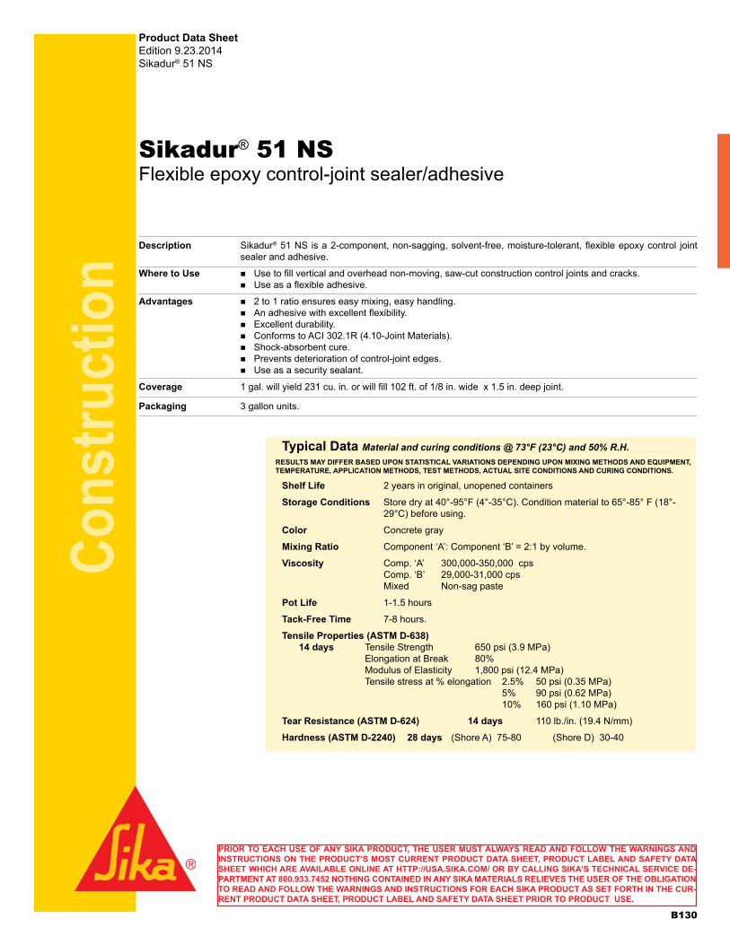
Cons
truct
ion
Sikadur® 51 NS Flexible epoxy control-joint sealer/adhesive
Description Sikadur® 51 NS is a 2-component, non-sagging, solvent-free, moisture-tolerant, flexible epoxy control joint sealer and adhesive.
Where to Use nUse to fill vertical and overhead non-moving, saw-cut construction control joints and cracks. nUse as a flexible adhesive.
Advantages n2 to 1 ratio ensures easy mixing, easy handling. nAn adhesive with excellent flexibility. nExcellent durability. nConforms to ACI 302.1R (4.10-Joint Materials). nShock-absorbent cure. nPrevents deterioration of control-joint edges. nUse as a security sealant.
Coverage 1 gal. will yield 231 cu. in. or will fill 102 ft. of 1/8 in. wide x 1.5 in. deep joint.
Packaging 3 gallon units.
Product Data SheetEdition 9.23.2014Sikadur® 51 NS
Typical Data Material and curing conditions @ 73°F (23°C) and 50% R.H.
Shelf Life 2 years in original, unopened containers
Storage Conditions Store dry at 40°-95°F (4°-35°C). Condition material to 65°-85° F (18°-29°C) before using.
Color Concrete gray
Mixing Ratio Component ‘A’: Component ‘B’ = 2:1 by volume.
Viscosity Comp. ‘A’ 300,000-350,000 cps Comp. ‘B’ 29,000-31,000 cps Mixed Non-sag paste
Pot Life 1-1.5 hours
Tack-Free Time 7-8 hours.
Tensile Properties (ASTM D-638) 14 days Tensile Strength 650 psi (3.9 MPa) Elongation at Break 80% Modulus of Elasticity 1,800 psi (12.4 MPa) Tensile stress at % elongation 2.5% 50 psi (0.35 MPa) 5% 90 psi (0.62 MPa) 10% 160 psi (1.10 MPa)
Tear Resistance (ASTM D-624) 14 days 110 lb./in. (19.4 N/mm)
Hardness (ASTM D-2240) 28 days (Shore A) 75-80 (Shore D) 30-40
RESULTS MAY DIFFER BASED UPON STATISTICAL VARIATIONS DEPENDING UPON MIXING METHODS AND EQUIPMENT, TEMPERATURE, APPLICATION METHODS, TEST METHODS, ACTUAL SITE CONDITIONS AND CURING CONDITIONS.
PRIOR TO EACH USE OF ANY SIKA PRODUCT, THE USER MUST ALWAYS READ AND FOLLOW THE WARNINGS AND INSTRUCTIONS ON THE PRODUCT’S MOST CURRENT PRODUCT DATA SHEET, PRODUCT LABEL AND SAFETY DATA SHEET WHICH ARE AVAILABLE ONLINE AT HTTP://USA.SIKA.COM/ OR BY CALLING SIKA’S TECHNICAL SERVICE DE-PARTMENT AT 800.933.7452 NOTHING CONTAINED IN ANY SIKA MATERIALS RELIEVES THE USER OF THE OBLIGATION TO READ AND FOLLOW THE WARNINGS AND INSTRUCTIONS FOR EACH SIKA PRODUCT AS SET FORTH IN THE CUR-RENT PRODUCT DATA SHEET, PRODUCT LABEL AND SAFETY DATA SHEET PRIOR TO PRODUCT USE.
B130
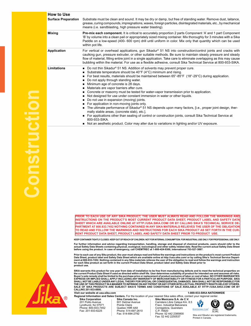
Cons
truct
ion
Visit our website at usa.sika.com 1-800-933-SIKA NATIONWIDERegional Information and Sales Centers. For the location of your nearest Sika sales office, contact your regional center.
Sika Corporation Sika Canada Inc. Sika Mexicana S.A. de C.V. 201 Polito Avenue 601 Delmar Avenue Carretera Libre Celaya Km. 8.5Lyndhurst, NJ 07071 Pointe Claire Fracc. Industrial BalvaneraPhone: 800-933-7452 Quebec H9R 4A9 Corregidora, QueretaroFax: 201-933-6225 Phone: 514-697-2610 C.P. 76920 Fax: 514-694-2792 Phone: 52 442 2385800
Fax: 52 442 2250537
KEEP CONTAINER TIGHTLY CLOSED. KEEP OUT OF REACH OF CHILDREN. NOT FOR INTERNAL CONSUMPTION. FOR INDUSTRIAL USE ONLY. FOR PROFESSIONAL USE ONLY.
For further information and advice regarding transportation, handling, storage and disposal of chemical products, users should refer to the actual Safety Data Sheets containing physical, ecological, toxicological and other safety related data. Read the current actual Safety Data Sheet before using the product. In case of emergency, call CHEMTREC at 1-800-424-9300, International 703-527-3887.
Prior to each use of any Sika product, the user must always read and follow the warnings and instructions on the product’s most current Product Data Sheet, product label and Safety Data Sheet which are available online at http://usa.sika.com/ or by calling Sika’s Technical Service Depart-ment at 800-933-7452. Nothing contained in any Sika materials relieves the user of the obligation to read and follow the warnings and instruction for each Sika product as set forth in the current Product Data Sheet, product label and Safety Data Sheet prior toproduct use.
SIKA warrants this product for one year from date of installation to be free from manufacturing defects and to meet the technical properties on the current Product Data Sheet if used as directed within shelf life. User determines suitability of product for intended use and assumes all risks. Buyer’s sole remedy shall be limited to the purchase price or replacement of product exclusive of labor or cost of labor. NO OTHER WARRANTIESEXPRESS OR IMPLIED SHALL APPLY INCLUDING ANY WARRANTY OF MERCHANTABILITY OR FITNESS FOR A PARTICULAR PURPOSE. SIKA SHALL NOT BE LIABLE UNDER ANY LEGAL THEORY FOR SPECIAL OR CONSEQUENTIAL DAMAGES. SIKA SHALL NOT BE RESPONSIBLE FOR THE USE OF THIS PRODUCT IN A MANNER TO INFRINGE ON ANY PATENT OR ANY OTHER INTELLECTUAL PROPERTY RIGHTS HELD BY OTHERS.SALE OF SIKA PRODUCTS ARE SUBJECT SIKA’S TERMS AND CONDITIONS OF SALE AVAILABLE AT HTTP://USA.SIKA.COM/ OR BYCALLING 201-933-8800.
ISO 9001Certificate # FM 69711
RC 14001Certificate # RC 510999
PRIOR TO EACH USE OF ANY SIKA PRODUCT, THE USER MUST ALWAYS READ AND FOLLOW THE WARNINGS AND INSTRUCTIONS ON THE PRODUCT’S MOST CURRENT PRODUCT DATA SHEET, PRODUCT LABEL AND SAFETY DATA SHEET WHICH ARE AVAILABLE ONLINE AT HTTP://USA.SIKA.COM/ OR BY CALLING SIKA’S TECHNICAL SERVICE DE-PARTMENT AT 800.933.7452 NOTHING CONTAINED IN ANY SIKA MATERIALS RELIEVES THE USER OF THE OBLIGATION TO READ AND FOLLOW THE WARNINGS AND INSTRUCTIONS FOR EACH SIKA PRODUCT AS SET FORTH IN THE CUR-RENT PRODUCT DATA SHEET, PRODUCT LABEL AND SAFETY DATA SHEET PRIOR TO PRODUCT USE.
Sika and Sikadur are registered trademarks. Printed in Canada.
How to UseSurface Preparation Substrate must be clean and sound. It may be dry or damp, but free of standing water. Remove dust, laitance,
grease, curing compounds, impregnations, waxes, foreign particles, disintegrated materials, etc., by mechanical means (i.e. sandblasting, high pressure water blasting).
Mixing Pre-mix each component. It is critical to accurately proportion 2 parts Component ‘A’ and 1 part Component ‘B’ by volume into a clean pail or appropriately sized mixing container. Mix thoroughly for 3 minutes with a Sika Paddle on a low-speed (400- 600 rpm) drill until uniform in color. Mix only that quantity which can be used within pot life.
Application For vertical or overhead applications, gun Sikadur® 51 NS into construction/control joints and cracks with caulking gun, pressure extruder, or other suitable methods. Be sure to maintain steady pressure and steady flow of material, filling entire joint in a single application. Take care to eliminate overlapping as this may cause bubbling within the material. For use as a flexible adhesive, consult Sika Technical Service at 800-933-SIKA.
Limitations nDo not thin Sikadur® 51 NS. Addition of solvents may prevent proper cure. nSubstrate temperature should be 40°F (4°C) minimum and rising. nFor best results, materials should be maintained between 65°-85°F (18°-29°C) during application. nDo not apply through standing water. nMinimum age of concrete is 28 days. nMaterials are vapor barriers after cure. nConcrete or masonry must be tested for water-vapor transmission prior to application. nNot designed for use under constant immersion in water or other liquids. nDo not use in expansion (moving) joints. nFor application in non-moving joints only. nThe ultimate performance of Sikadur® 51 NS depends upon many factors, [i.e., proper joint design, ther-
mally stable areas, (concrete slab), etc.]. nFor applications other than sealing of control or construction joints, consult Sika Technical Service at
800-933-SIKA. nNot an aesthetic product. Color may alter due to variations in lighting and/or UV exposure.
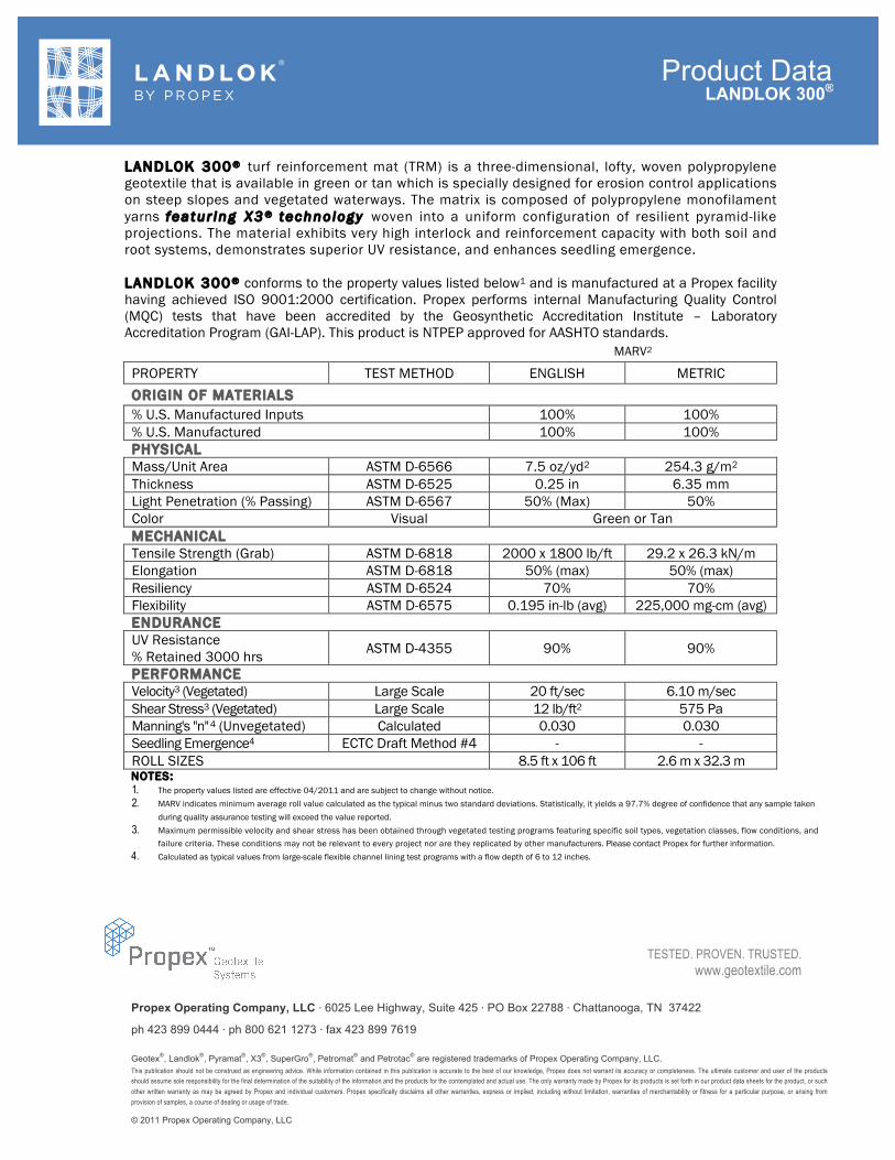
Propex Operating Company, LLC ⋅ 6025 Lee Highway, Suite 425 ⋅ PO Box 22788 ⋅ Chattanooga, TN 37422
ph 423 899 0444 ⋅ ph 800 621 1273 ⋅ fax 423 899 7619 Geotex®, Landlok®, Pyramat®, X3®, SuperGro®, Petromat® and Petrotac® are registered trademarks of Propex Operating Company, LLC. This publication should not be construed as engineering advice. While information contained in this publication is accurate to the best of our knowledge, Propex does not warrant its accuracy or completeness. The ultimate customer and user of the products
should assume sole responsibility for the final determination of the suitability of the information and the products for the contemplated and actual use. The only warranty made by Propex for its products is set forth in our product data sheets for the product, or such
other written warranty as may be agreed by Propex and individual customers. Propex specifically disclaims all other warranties, express or implied, including without limitation, warranties of merchantability or fitness for a particular purpose, or arising from
provision of samples, a course of dealing or usage of trade.
© 2011 Propex Operating Company, LLC
Product Data
TESTED. PROVEN. TRUSTED. www.geotextile.com
LANDLOK 300 ® turf reinforcement mat (TRM) is a three-dimensional, lofty, woven polypropylene geotextile that is available in green or tan which is specially designed for erosion control applications on steep slopes and vegetated waterways. The matrix is composed of polypropylene monofilament yarns f e a t u r i n g X 3 ® t e c h n o l o g y woven into a uniform configuration of resilient pyramid-like projections. The material exhibits very high interlock and reinforcement capacity with both soil and root systems, demonstrates superior UV resistance, and enhances seedling emergence. LANDLOK 300 ® conforms to the property values listed below1 and is manufactured at a Propex facility having achieved ISO 9001:2000 certification. Propex performs internal Manufacturing Quality Control (MQC) tests that have been accredited by the Geosynthetic Accreditation Institute – Laboratory Accreditation Program (GAI-LAP). This product is NTPEP approved for AASHTO standards. MARV2 PROPERTY TEST METHOD ENGLISH METRIC ORIGIN OF MATERIALS % U.S. Manufactured Inputs 100% 100% % U.S. Manufactured 100% 100% PHYSICAL Mass/Unit Area ASTM D-6566 7.5 oz/yd2 254.3 g/m2
Thickness ASTM D-6525 0.25 in 6.35 mm Light Penetration (% Passing) ASTM D-6567 50% (Max) 50% Color Visual Green or Tan MECHANICAL Tensile Strength (Grab) ASTM D-6818 2000 x 1800 lb/ft 29.2 x 26.3 kN/m Elongation ASTM D-6818 50% (max) 50% (max) Resiliency ASTM D-6524 70% 70% Flexibility ASTM D-6575 0.195 in-lb (avg) 225,000 mg-cm (avg) ENDURANCE UV Resistance % Retained 3000 hrs ASTM D-4355 90% 90%
PERFORMANCE Velocity3 (Vegetated) Large Scale 20 ft/sec 6.10 m/sec
Shear Stress3 (Vegetated) Large Scale 12 lb/ft2 575 Pa Manning's "n" 4 (Unvegetated) Calculated 0.030 0.030 Seedling Emergence4 ECTC Draft Method #4 - - ROLL SIZES 8.5 ft x 106 ft 2.6 m x 32.3 m NOTES: 1. The property values listed are effective 04/2011 and are subject to change without notice. 2. MARV indicates minimum average roll value calculated as the typical minus two standard deviations. Statistically, it yields a 97.7% degree of confidence that any sample taken
during quality assurance testing will exceed the value reported. 3. Maximum permissible velocity and shear stress has been obtained through vegetated testing programs featuring specific soil types, vegetation classes, flow conditions, and
failure criteria. These conditions may not be relevant to every project nor are they replicated by other manufacturers. Please contact Propex for further information. 4. Calculated as typical values from large-scale flexible channel lining test programs with a flow depth of 6 to 12 inches.
LANDLOK 300®