Embed Size (px)
Citation preview
. EL = ~·~·
~ ~ MENBEBS L£GEND h-h ... ~ A • V2 1/2x2 1/2x3/16 v ANTENNA Tx-Une B ,. lt 1/2xt 1/2x1/8 ~ Description ~· ~fi)· ,~r Description C = l3x3x3/16 v
lc lm :Sic D .. V3 1/2x3 1/2x1/4 ~b:. 7~~ " DB-589Y 25.9 85 0 1 LDfSP-SOA
E = l1 3/4x1 3/4x3/16 h-h = . k Pl2 24.4 80 180 2 L.Or4P-50A Pl2 24.4 80 60 2 L.Or4P-50A
,~ B<l.TS l.f.:~D K Pl2 24.4 80 240 2 L.Or4P-50A
I~ A • {1) 1/2 in A325 Pl2 24.4 80 120 2 L.Or4P-50A lm ~c EL "6~.~ l/ Pl2 24.4 80 0 2 L.Or4P-50A
SPUCE !I<US L£GEND !'-... 25X loading 24.4 80 0 h-h = .. A .. (8) 1/2 in AJ25/leg K (t.l PCTEL Moxrod 22.9 75 0 (2) LDr4P-50A B .. (12) 1/2 in AJ25/leg
lo lm I~ lc D..~·~· K STEP BOLTS c!c SAfETY CABL£ h-h .. . ~ v
[) 1\ I~ ml~ D Q c EL • ~·88' I \ z
[> h-h ... I
L~~ [> 0 lm I~ lc c EL • ~·W' [> h-h ... I
T06 CROSS SECTION
,5 [> RECEIVED ~ ,.... > 1::.:: lm 1:;:; c ~ .. 2QI~ -h • 3. • l> JAN 2 6 2012 15 [) GARFIELD COUNTY ~ 1::.:: ... I~ lc ~~.. . ~~~· t> BUILDING & PLANNING
h-h • • I
... t> 15 lr DIRECT EMBED TOYttR SEC110N BY lR'!tON- TSF. SEE rDN. DV«l. ~ ...IS1 ~~ El - 0' '> ,::_:: lc lm h-h - 4-:oo'
':a I!! 11 1-=
h ~ ~~ ;; tt LEG EWMD!D!Jtj LQ!DS GUII!L EWMD!DW LQ!DS
!
a ~~ Nox Download • 89 (Kips) Mox Axkll = 3 (Kips)
§~ ~~ Nox Uplift " 79 (Kips) Max ON = 306 (Kipsft)
ii Nox Shear " 4 (Kips) Mox Shear= 6 (Klps)
DESIGN CODE: EIA-222- G BASIC 3 SEC. GUST ~NO SPEED: 90.0 (mph) BASIC 3 SEC. GUST ~NO SPEED ~TH ICE: 50.0 (mph) BASIC ICE lHICKNESS: 0.25 (in) EXPOSURE CATEGORY: C IMPORTANCE CLASS:2
CONFlOENTlAl: All INTEU£C11JIL PROPERTY RIGHlS HEREIN ARE lHE PROPERlY Or lR'!tON TSr Inc. All OUPUCA110N, RECOROING, DISCLOSURE OR USE IS PROHIBITED WITHOUT WRITTEN CONSENT or TRYLON TSE,...Iac.
REV • REV. CHK. DESCRIPTION DATE ..cP"::-nn 1 ~ BY: BY:
NOTES: 'IJJ'f.!i•· .. ·~·-=~~~ UTRYLON Tn ~··~R. H~··. IS' Bl.tJ "'<\(~ .
{ PE-415~1 ~ .... ~ CUSTOMER: ; ISITE: SCALE:
THINAJR COMMUNICATIONS PN30, CO 15 ............. DATE: I BY: ICHK: l APP: 12 JAN 12 ss
._ TITLE: DRAWING NO.
,,. '"'1,. 80' H510 81039 .
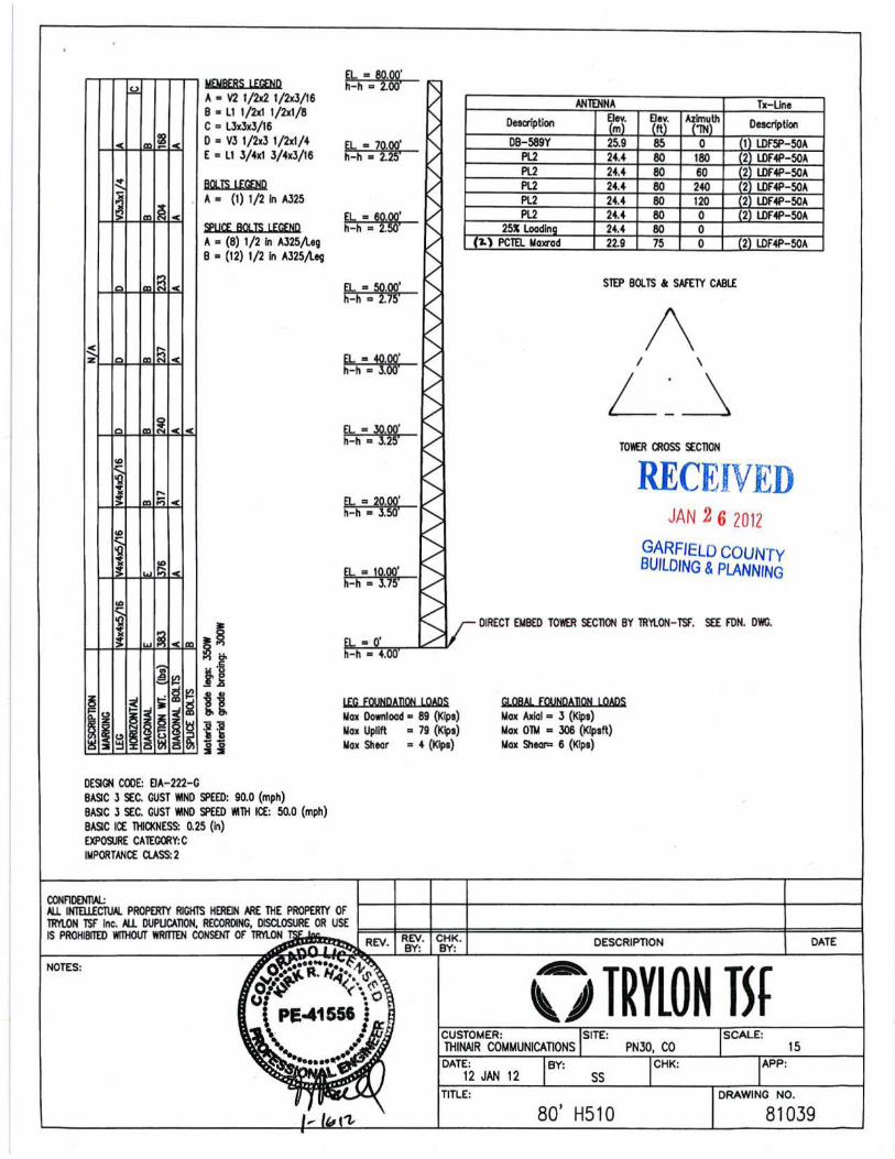
/Total Concre te - 12.3 C.Y. o· t 1rec em e b d tower section
. See Try/on by Try/on TSF
1 1\.
installation d wgs for embedment, c. C/L tower & orientation et n coincide. ' "' C/L foundatio
\: /)<,~ /X"\ /)<,~
\ 66" SQ Pie 12" Min. (36
1'-0'
T r
) #6 Bars Embed 'I>
#4 <.o I _L
Ties on 6" c/c 'in
"'=' """-
-'-- -1 '-6"
T -..... ......
#6 Bars at 12" c/c - top & bottom
9" Min. Bend~!'--Shea
- both ways
r Key FOUNDATION NOTES: 11'-0" X 11'-0" form w/2"x6"x18" long GENERAL: 1) ALL WORKMANSHIP AND MATERIALS SHALL BE IN ACCORDANCE WITH APPLICABLE LOCAL STANDARDS. 2) FOUNDATIONS DESIGNED BASED ON GEOTECHNICAL REPORT BY CTL REF GS05622-125 DATED DEC 20, 2011
NO ALLOWANCE WAS MADE FOR SOFT SOILS, FILL, PEATS, ORGANICS, WATER, OR ROCK IN EXCAVATION. 3) THE TOWER BASE PAD SHALL BE PLACED AGAINST UNDISTURBED SOIL.
CONCRETE SHALL HAVE A MINIMUM COMPRESSIVE STRENGTH AT 28 DAYS OF NOT LESS THAN 4000 psi. CONCRETE SHALL CONTAIN AN AIR ENTRAINING AGENT. THE MAXIMUM SIZE OF COARSE AGGREGATE SHALL BE 3/4". SLUMP SHALL BE 4 in +/- 1 in
4) ALL GROUT SHALL BE NON-FERROUS AND NON SHRINK WITH A MINIMUM COMPRESSIVE STRENGTH OF 5000 psi AT 28 DAYS, EDGES GROUT SHALL BE TAPERED OFF AT 45'.
ALL REINFORCEMENT SHALL HAVE 3 in CONCRETE COVER. 2) REINFORCING STEEL SHALL BE ASTM A615 DEFORMED BARS WITH A MINIMUM YIELD OF 60 ksi.
I BACKFILL SHALL BE PLACED IN THIN LIFTS {MAXIMUM 6 in) AND COMPACTED TO A MINIMUM OF 95 PERCENT OF STANDARD PROCTOR MAXIMUM DRY DENSITY {100 pet min.). IN THE EVENT THAT EXCAVATED MATERIALS ARE NOT SUITABLE FOR BACKFILL, IT SHALL BE THE RESPONSIBILITY OF THE CONTRACTOR TO SUPPLY AND COMPACT SUITABLE CLEAN MATERIAL TO MEET THAT REQUIREMENT.
NOTES:
15
80' H51 0 81039
•
' ~
' ~ ~
f.- f.- ~~ f.-
• ' ~ s '
I- f.- f.-~ f.-
' ' •
I-§
h1- f-~ " • " ~
' ~ ' s
~ ~ N
I- 1-w Of-~
' '
- I-- ~~ -
' '
f- f- ~ f-
• , I • > •
I- i 1-1!- f.-
~ "' "
' •
N
~ g g
j I I e ~ 0 g
I ~ d • J ! ~ • • l
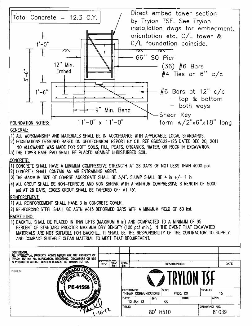
DESIGNED APPURTENANCE LOADING TYPE lYPE
; 80
~ P2 80
~ P2
180 IP2
MATERIAL STRENGTH
I .. ~~DE I Fy .""".. 51 ksl !65ksl Fu Iss ksi Fu
TOWER DESIGN NOTES 1. Tower is located in Garfield County, Colorado. 2. Tower designed for Exposure C to the TIA-222-G Standard. 3. Tower designed for a 90 mph basic wind in accordance with the TIA-222-G Standard. 4. Tower is also designed for a 50 mph basic wind with 0.25 in ice. Ice is considered to
increase in thickness with height. 5. Deflections are based upon a 60 mph wind. 6. Tower Structure Class II. 7. Topographic Category 1 with Crest Height of 0.00 ft 8. TOWER RATING: 90.4%
ALL REACTIONS ARE FACTORED
M~. CORNER REACTIONS AT BASE: DOWN: 89K UPLIFT: -79 K SHEAR: 4K
~IAL 6K
SHEAR~ MOMENT 2KLj \ 79kip-ff
TORQUE 0 kip-n 50 mph WIND - 0.2500 in ICE
~IAL 3K
SHEAR~ MOMENT aKU \ 306kip-n
TORQUE 1 kip-n REACTIONS- 90 mph WIND
World Tower Company ~,. Q11-1084 Pn>Joa: 80' Hiiih Mesa PN30 CO 1213 Compressor Drive
Mayfield, Kentucky 42066 Client Trvlon #81 039 for ThinAir CommunicatlonsfDravm by: Kirk Hal App'd:
Phone: (270) 247-3642 Code: TIA-222-G loate:01115112 scale: NH FAX: 12701.247-0909 """ osu-'. DwgNo. E-·
RJSATower Job
011-1084
World Tower Company Project
I 213 Compressor Drive 80' High Mesa PN30, CO Mayfield, Kentucky 42066 Client
Phone: (270) 247-3642 Trylon #81039 for ThinAir Communications FAX (270) 247-0909
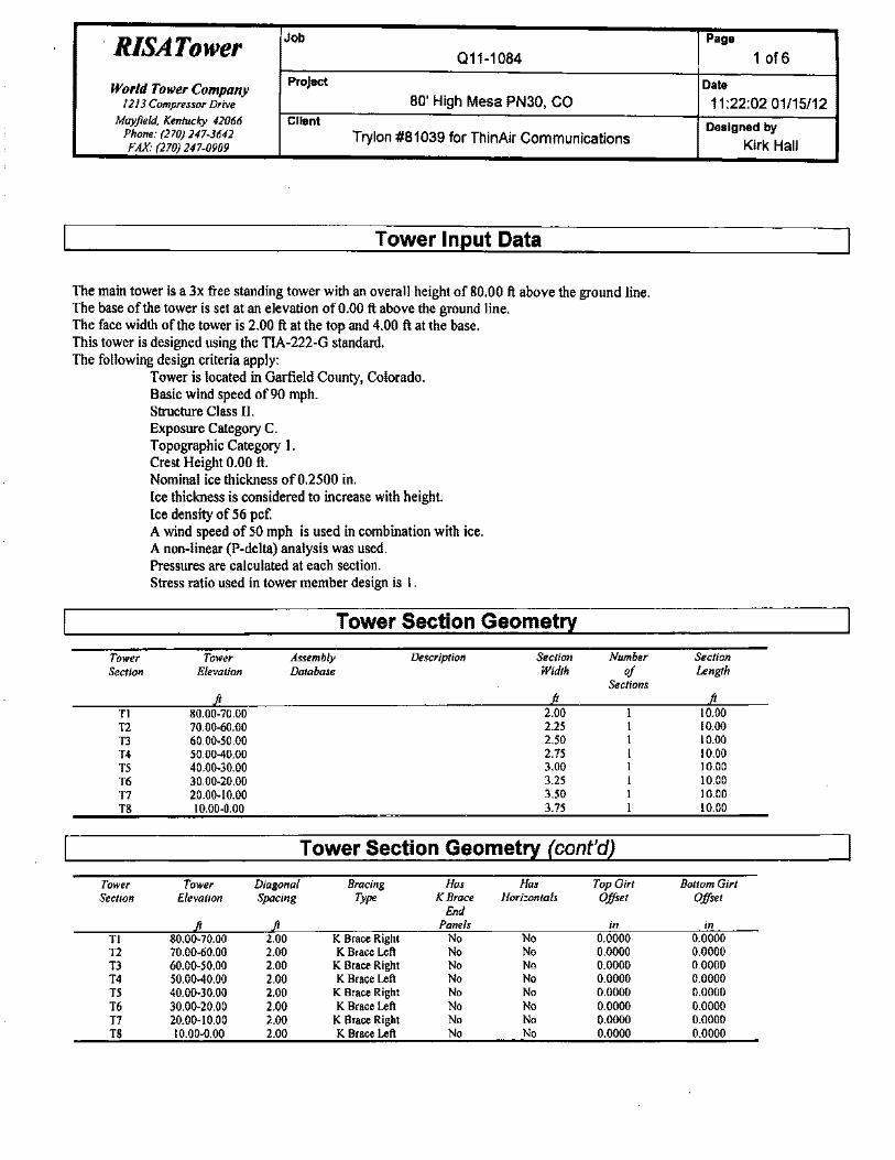
Tower Input Data
The main tower is a 3x free standing tower with an overall height of 80.00 ft above the ground line. The base of the tower is set at an elevation ofO.OO ft above the ground line. The face width of the tower is 2.00 ft at the top and 4.00 ft at the base. This tower is designed using the TIA-222-G standard. The following design criteria apply:
Tower is located in Garfield County, Colorado. Basic wind speed of90 mph. Structure Class II. Exposure Category C. Topographic Category I. Crest Height 0.00 ft. Nominal ice thickness of0.2500 in. Ice thickness is considered to increase with height. Ice density of 56 pcf. A wind speed of 50 mph is used in combination with ice. A non-linear (P-delta) analysis was used. Pressures are calculated at each section. Stress ratio used in tower member design is I.
Tower Section Geometry
Tower Section
Tl T2 T3 T4 T5 T6 T7 T8
Tower Elevation
80.00-70.00 70.00-60.00 60.00-50.00 50.00-40.00 40.00-30.00 30.00-20.00 20.00-10.00 10.00-0.00
Assembly Database
Description Sec lion Width
2.00 2.25 2.50 2.75 3.00 3.25 3.50 3.75
Number of
Sections
Tower Section Geometry (cont'd)
Tower Tower Diagonal Bracing Hos Hos Top Girt Section Elevation Spacing Type K Brace Horizontals Offset
End Panels in
Tl 80.00-70.00 2.00 K Brace Right No No 0.0000 T2 70.00-60.00 2.00 K Brace Left No No 0.0000 T3 60.00-50.00 2.00 K Brace Right No No 0.0000 T4 50.00-40.00 2.00 K Brace Left No No 0.0000 T5 40.00-30.00 2.00 K Brace Right No No 0.0000 T6 30.00-20.00 2.00 K Brace Left No No 0.0000 T7 20.00-10.00 2.00 K Brace Right No No 0.0000 TS 10.00-0.00 2.00 K Brace Left No No 0.0000
Page
1 of6
Date
11:22:02 01/15/12
Designed by
Section Length
10.00 10.00 10.00 10.00 10.00 10.00 10.00 10.00
Bottom Girl Offset
in 0.0000 0.0000 0.0000 0.0000 0.0000 0.0000 0.0000 0.0000
Kirk Hall
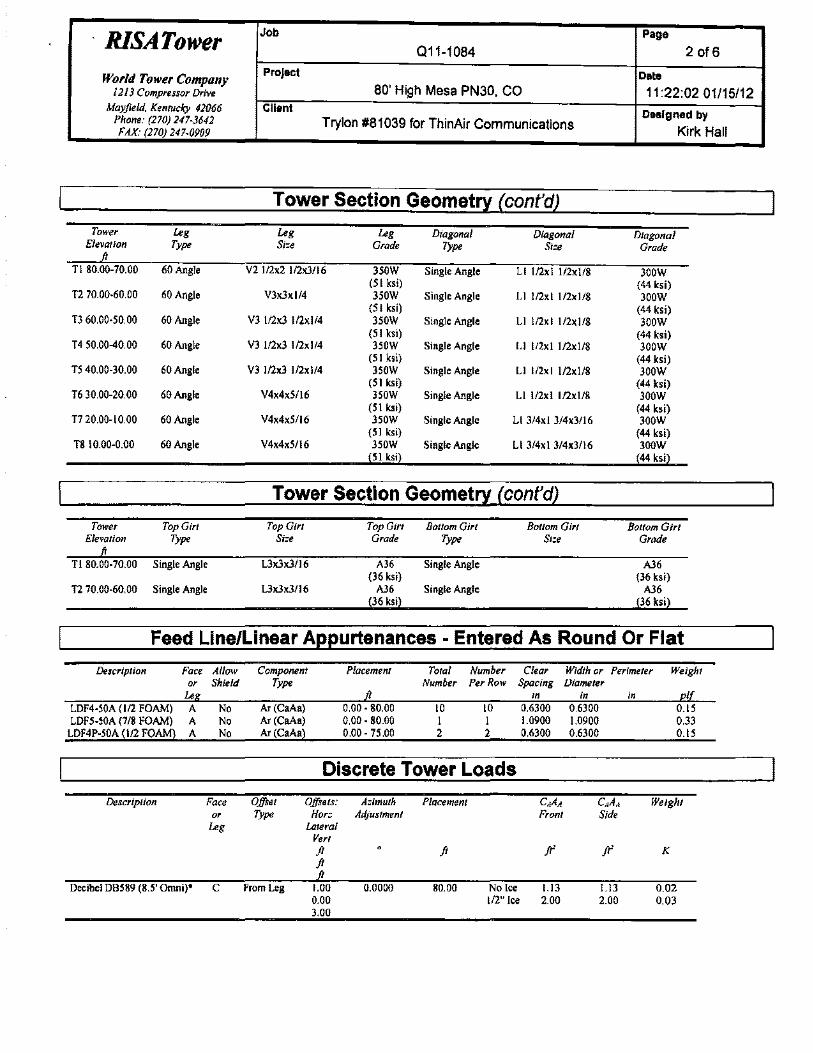
RISATower Job Page
011-1084 2 of6
World Tower Company Project Date 1213 Compressor Drive 80' High Mesa PN30, CO 11:22:02 01/15/12
Mayfield, Kentucky 42066 Client Designed by Phone: (270) 247-3642 Trylon #81 039 for ThinAir Communications
FAX: (270) 247-0909 Kirk Hall
Tower Section Geometry (cont'dl
Tower Leg Leg Leg Diagonal Diagonal Diagonal Elevation Type Si=e Grade Type Si=e Grade
T1 80.00-70.00 60 Angle V2 1/2x2 l/2x3/16 350W Single Angle Ll l/2x I l/2x 1/8 300W (5 I ksi) (44 ksi)
T2 70.00-60.00 60 Angle V3x3xl/4 350W Single Angle Ll l/2xl l/2xl/8 300W (5 I ksi) (44 ksi)
T3 60.00-50.00 60 Angle V3 l/2x3 l/2xl/4 350W Single Angle Ll l/2xl l/2xl/8 300W (5 I ksi) (44 ksi)
T4 50.00-40.00 60 Angle V3 l/2x3 l/2xl/4 350W Single Angle L I l/2x I l/2x 1/8 300W (5 I ksi) (44 ksi)
T5 40.00-30.00 60 Angle V3 l/2x3 1/2xl/4 350W Single Angle Ll l/2x I l/2x 1/8 300W (51 ksi) (44 ksi)
T6 30.00-20.00 60Angle V4x4x5/16 350W Single Angle Ll l/2xl l/2xl/8 300W (5 I ksi) (44 ksi)
T7 20.00-10.00 60Angle V4x4x5/16 350W Single Angle Ll 3/4xl 3/4x3/16 300W (5 I ksi) (44 ksi)
T8 10.00-0.00 60 Angle V4x4x5/16 350W Single Angle Ll 3/4x I 3/4x3/16 300W 51 ksi
Tower Section Geomet!1 (cont'dl
Tower Top Girt Top Girt Top Girt Bottom Girt Bottom Girt Bottom Girt Elevation Type Si=e Grade Type Si=e Grade
T1 80.00-70.00 Single Angle L3x3x3/16 Single Angle
T2 70.00-60.00 Single Angle L3x3x3/16 Single Angle
Feed Line/Linear Appurtenances - Entered As Round Or Flat
Description Face Allow Component Placement Total Number Clear Width· or Perimeter Weight or Shield Type Number PerRow Spacing Diameter
Le in in in I LDF4-50A (1/2 FOAM) A No Ar (CaAa) 0.00-80.00 10 10 0.6300 0.6300 0.15 LDF5-50A (7/8 FOAM) A No Ar (CaAa) 0.00-80.00 I I 1.0900 1.0900 0.33
LDF4P-50A (1/2 FOAM) A No Ar (CaAa) 0.00-75.00 2 2 0.6300 0.6300 0.15
Discrete Tower Loads
Description Face Offset Offsets: A=imuth Placemenl CAAA CAAA Weight or Type Hor= Adjustment Fronl Side
Leg Lateral Vert ji ji ft' ft' K ji
Decibel DB589 (8.5' Omni)' C From Leg 1.00 0.0000 80.00 No lee 1.13 1.13 0.02 0.00 1/2" Ice 2.00 2.00 0,03 3.00
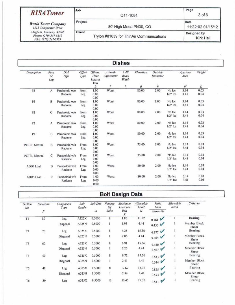
. RISATower Job Page
011-1084 3 of6
World Tower Company Project Date
1213 Compressor Drive 80' High Mesa PN30, CO 11 :22:02 01/15/12 Mayfield, Kentucky 42066 Client Designed by
Phone: (270) 247-3642 Trylon #81039 for ThinAir Communications FAX: (270) 247-0909 Kirk Hall
Dishes
Dcscriplion Face Dish Offset Offse/s: A:imuth 3d8 Eleva/ion Oulside Aperllm: Weigh/ or Type Type /-lor: Adjustment Beam Diameter Area Leg Lateral Width
Vert [I 0 [I [I rr K
P2 A Paraboloid w/o From 1.00 Worst 80.00 2.00 No Icc 3. 14 O.Q3 Radomc Leg 0.00 1/2" Ice 3.41 0.04
0.00 P2 B Paraboloid w/o From 1.00 Worst 80.00 2.00 No Icc 3.14 0.03
Radomc Leg 0.00 1/2" Icc 3.4 1 0.04 0.00
P2 c Paraboloid w/o From 1.00 Worst 80.00 2.00 No Icc 3.14 0.03 Radomc Leg 0.00 112" Icc 3.4 1 0.04
0.00 P2 A Paraboloid w/o From 1.00 Worst 80.00 2.00 No Icc 3.14 0.03
Radome Leg 0.00 1/2" Icc 3.41 0.04 0.00
P2 B Paraboloid w/o From 1.00 Worst 80.00 2.00 No Icc 3.14 0.03 Radome Leg 0.00 1/2" Icc 3.4 1 0.04
0.00 PCTEL Maxrad B Paraboloid w/o From 1.00 Worst 75.00 2.00 No Icc 3. 14 0.03
Radome Leg 0.00 1/2" Icc 3.41 0.04 0.00
PCTEL Maxrad c Paraboloid w/o From 1.00 Worst 75.00 2.00 No Icc 3.14 0.03 Radome Leg 0.00 1/2" tee 3.41 0.04
0.00 ADD'l Load B Paraboloid w/o From 1.00 Worst 80.00 2.00 No Icc 3.14 0.03
Radome Leg 0.00 112" Icc 3.4 1 0.04 0.00
ADD'l Load c Paraboloid w/o Fro1_n 1.00 Worst 80.00 2.00 No Icc 3.14 0.03 Radome Leg o.oa 112" Ice 3.41 0.04
0.00
Bolt Design Data
Section Elevation Component Bolt Bolt Si:e Number Maximum Allowable Ratio Allowable Criteria
No. 7)•pe Grade Of Load per Load Load Ratio
ft in /Jolts Bolt K Allowable K
Tl 80 Leg A325X 0.5000 8 1.86 11 .52 0.161 v Bearing
Diagonal A325N 0.5000 1.93 4.44 0.435 V' Member Block Shear
T2 70 Leg A325X 0.5000 8 4.25 15.36 0.277 V' Bearing
Diagonal A325N 0.5000 2.06 4.44 0.464 V' Member Block Shear
T3 60 Leg A325X 0.5000 8 6.91 15.36 0.450 V' Bearing
Diagonal A325N 0.5000 2.25 4.44 0.507 V' Member Block Shear
T4 50 Leg A325X 0.5000 8 9.72 15.36 0.633 V' Bearing
Diagonal A325N 0.5000 2.4 1 4.44 0.544 V' Member Block Shear
TS 40 Leg A325X 0.5000 8 12.67 15.36 0.825 V' Bearing
Diagonal A325N 0.5000 2.54 4.44 0.573 V' Member Block Shear
T6 30 Leg A325X 0.5000 12 10.45 19.33 0.54 1 v Bearing
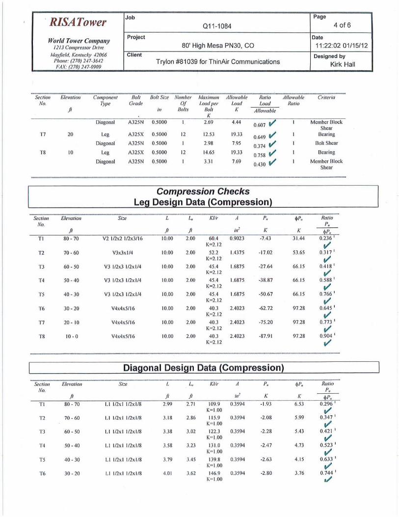
· RISATower Job Page
01 1-1084 4 of 6
World Tower Company Project Date
1213 Compressor Drive 80' High Mesa PN30, CO 11:22:02 01/15/12 ,\-Iayfieid, Kentudy 42066 Client Designed by
Phone: (270) 247-3642 Trylon #81039 for ThinAir Communications Kirk Hall FAX: (270) 247-0909
Section Elevation Component Bolt Bolt Si:e Number Maximum Allowable Ratio Allowable Criteria No. Type Grade Of Load per Load Load Ratio
ft ill Botts 8oft K Allowabfe K
Diagonal A325N 0.5000 2.69 4.44 0.607 tl' Member Block
Shear T7 20 Leg A3 25X 0.5000 12 12.53 19.33
0.649 v Bearing
Diagonal A325N 0.5000 2.98 7.95 0.374 tl' Bolt Shear
T8 10 Leg A325X 0.5000 12 14.65 19.33 0.758 tl' Bearing
Diagonal A325N 0.5000 3.3 1 7.69 0.430 v Member Block
Shear
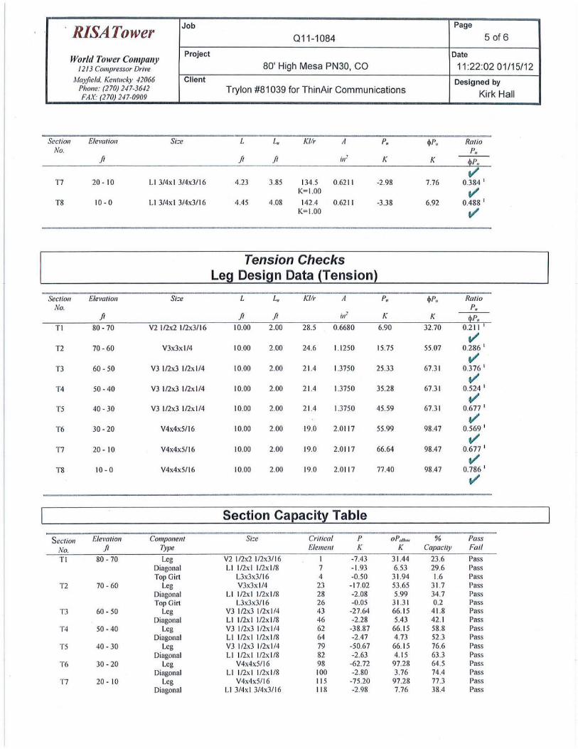
Compression Checks Leg Design Data (Compression)
Section Elevation Si:e L L. Kllr A P, ~P .. Ratio No. P,
ft ft ft in~ K K P, Tl 80-70 V2 112x2 I /2x3/ 16 10.00 2.00 60.4 0.9023 -7.43 3 1.44 0.236 1
K=2. 12 1/ T2 70-60 V3x3x l /4 10.00 2.00 52.2 1.4375 -17.02 53.65 0.317 1
K=2.12 v T3 60 - 50 V3 l/2x3 l/2x l /4 10.00 2.00 45.4 1.6875 -27.64 66.15 0.4 18 1
K=2. 12 v T4 50-40 V3 l/2x3 l /2x 1/4 10.00 2.00 45.4 1.6875 -38.87 66.15 0.588 1
K=2.12 v TS 40 - 30 V3 l/2x3 1/2x 1/4 10.00 2.00 45.4 I .6875 -50.67 66. 15 0.766 1
K=2.12 t/ T6 30-20 V4x4x5/16 10.00 2.00 40.3 2.4023 -62.72 97.28 0.645 1
K=2 .12 .,. T7 20 - 10 V4x4x5/16 10.00 2.00 40.3 2.4023 -75.20 97.28 0.773 1
K=2. 12 v T8 10- 0 V4x4x5/16 10.00 2.00 40.3 2.4023 -87.9 1 97.28 0.904 1
K=2.12 V'
Diagonal Design Data {Com~ression}
Section Elevation Si:e L L, Kflr A P, ~P .. Ratio No. P,
ft ft ft ;n! K K P, T l 80 -70 Ll l/2x I l /2x 1/8 2.99 2.71 109.9 0.3594 -1.93 6.53 0.296 1
K=I.OO v T2 70-60 Ll l/2x l l/2x l/8 3.18 2.86 II 5.9 0.3594 -2.08 5.99 0.347 1
K= I. OO v T3 60 - 50 Ll l/2x l l/2x l/8 3.38 3.02 122.3 0.3594 -2.28 5.43 0.42 1 1
K= I. OO v T4 50-40 Ll l/2x l l/2x l/8 3.58 3.23 13 1.0 0.3594 -2.47 4.73 0.523 1
K= I.OO v' TS 40 - 30 Ll l/2xl l/2x l /8 3.79 3.45 139.8 0.3594 -2.63 4. 15 0.633 1
K= I.OO v T6 30-20 Ll l/2x l l /2x l /8 4.01 3.62 146.9 0.3594 -2.80 3.76 0.744 1
K= I.OO a/
. RISATower Job Page
Q11-1084 5 of6
World Tower Company Project Date
1213 Compressor Drive 80' High Mesa PN30, CO 11 :22:02 01/15/12 A4a>freld. Kentuci.J' 42066 Client Designed by
Phone: (270) 247-3642 Trylon #81 039 for ThinAir Communications FAX: (270) 247-0909 Kirk Ha ll
Section Elevation Si=e L /.., Kllr A P, $P, Ratio No. P,
ft ft ft . ' Ill" K K P,
v T7 20- 10 Ll 3/4x I 3/4x3/ 16 4.23 3.85 134.5 0.6211 -2.98 7.76 0.384 I
K= I.OO V' T8 10-0 Ll 3/4x I 3/4x3/16 4.45 4.08 142.4 0.621 1 -3.38 6.92 0.488 I
K= I.OO v'
Tension Checks Leg Design Data (Tension)
Section Elevation Si=e L L, Kllr A P, $P, Ratio No. P,
ft ft ft in: K K P, Tl 80-70 Y2 l /2x2 I /2x3/ 16 10.00 2.00 28.5 0.6680 6.90 32.70 0.2 11 I
V' T2 70-60 V3x3x l/4 10.00 2.00 24.6 1.1 250 15.75 55.07 0.286 I
v T3 60- 50 Y3 l/2x3 1/2xl/4 10.00 2.00 21.4 1.3750 25.33 67.3 1 0.376 I
v T4 50-40 V3 l/2x3 l/2x 1/4 10.00 2.00 21.4 1.3750 35.28 67.3 1 0.524 1
v TS 40-30 Y3 l /2x3 l/2xl/4 10.00 2.00 21.4 1.3750 45.59 67.31 0.677 I
v T6 30 - 20 V4x4x5/ 16 10.00 2.00 19.0 2.011 7 55.99 98.47 0.569 I
v' T7 20- 10 V4x4x5/16 10.00 2.00 19.0 2.01 17 66.64 98.47 0.677 I
1/ T8 10-0 V4x4x5/16 10.00 2.00 19.0 2.0 117 77.40 98.47 0.786 I
v
Section Capacity Table
Section Elevation Component Si=e Critical p oPtlllm1· % Pass
No. ft Type Element K K Capacity Fail
Tl 80-70 Leg V2 l /2x2 l/2x3/ 16 I -7.43 31.44 23.6 Pass Diagonal Ll l/2xl 1/2:\1/8 7 -1.93 6.53 29.6 Pass Top Girl L3x3x3/16 4 -0.50 31.94 1.6 Pass
T2 70-60 Leg V3x3x 1/4 23 -17.02 53.65 31.7 Pass Diagonal Ll l /2xl l /2x l /8 28 -2 .08 5.99 34.7 Pass Top Girl L3x3x3/16 26 -0.05 31.3 1 0.2 Pass
T3 60- 50 Leg V3 l/2x3 l/2x l /4 43 -27.64 66. 15 41.8 Pass Diagonal Ll l /2xl l/2x l /8 46 -2.28 5.43 42. 1 Pass
T4 50-40 Leg V3 l /2x3 l /2x l /4 62 -38.87 66. 15 58.8 Pass Diagonal L I l /2x I l/2x 1/8 64 -2.47 4.73 52.3 Pass
TS 40-30 Leg V3 l /2x3 1/2xl /4 79 -50.67 66.15 76.6 Pass Diagonal Ll l /2x l l/2x l/8 82 -2.63 4. 15 63.3 Pass
T6 30-20 Leg V4x4x5/16 98 -62.72 97.28 64.5 Pass Diagonal L I l/2x l l/2x 1/8 100 -2.80 3.76 74.4 Pass
T7 20 - 10 Leg V4x4x5/ 16 115 -75.20 97.28 77.3 Pass Diagonal L I 3/4x I 3/4x3!16 118 -2.98 7.76 38.4 Pass
RISATower Job Page
011-1084 6 of6
World Tower Company Project Date
I 213 Compressor Drive 80' High Mesa PN30, CO 11:22:02 01/15/12 Mayfield, Kentucky 42066 Client Designed by
Phone: (270) 247-3642 Trylon #81039 for ThinAir Communications Kirk Hall FAX: (270) 247-0909
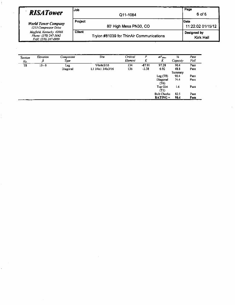
Section Elevation Component Si=e Critical p flPollow % Pass
No. fi Type Element K K Capacity Fail
T8 10-0 Leg V4x4x5/16 134 -87.91 97.28 90.4 Pass Diagonal Ll 3/4xl 3/4x3/16 136 -3.38 6.92 48.8 Pass
Summary Leg (T8) 90.4 Pass Diagonal 74.4 Pass
(T6) Top Girt 1.6 Pass
(TI) Bolt Checks 82.5 Pass RATING= 90.4 Pass
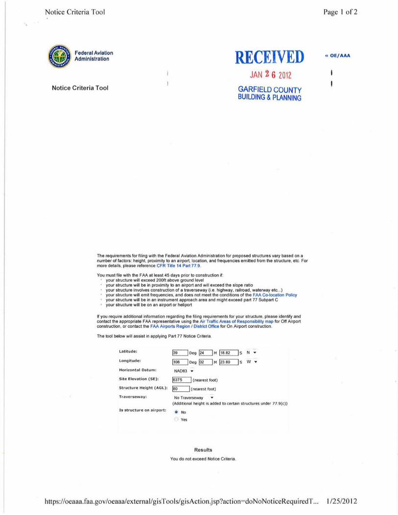
Notice Criteri a Too l
Federal Aviation Administration RECEIVED
Notice Criteria Tool
JAN 2 6 2012
GARFIELD COUNTY BUILDING & PLANNING
The requirements for f iling with the Federal Aviation Administration for proposed structures vary based on a number of factors: height, proximity to an airport, location, and frequencies emitted from the structure, etc. For more details, please reference CFR Title 14 Part 77.9.
You must file with the FAA at least 45 days prior to construction if: your structure will exceed 200ft above ground level your structure will be in proximity to an airport and will exceed the slope ratio your structure involves construction of a traverseway {i.e. highway, ra~road , waterway etc ... ) your structure will emit frequencies, and does not meet the conditions of the FAA Co-location Policy your structure will be in an instrument approach area and might exceed part 77 Subpart C your structure will be on an airport or heliport
If you require additional information regarding the filing requirements for your structure, please identify and contact the appropriate FAA representative using the Air Traffic Areas of Responsibility map for Off Airport construction, or contact the FAA Airports Region I District Offoce for On Airport construction .
The tool below will assist in applying Part 77 Notice Criteria.
l atitude:
l ongitude:
Horizonta l Datum:
Site Elevation (SE):
Structure Height (AGl):
Traverseway :
I s structure on airport:
~Deg~M~S NT
~Deg~M ~S w T
NA083 T
~(nearest foot)
~(nearest foot)
No T raverseway (Additional height is added to certain structures under 77.9(c))
G No
Yes
Results
You do not exceed Notice Criteria.
https://oeaaa.faa.gov/oeaaa/external/gisTools/gisAction.jsp?action=doNoNoticeRequiredT ...
Page I of2
« OE/AAA
1/25/201 2
Notice Criteria Tool Page 2 of 2
https://oeaaa.faa.gov/oeaaa/external/gisTools/gisAction.jsp?action=doNoNoticeRequiredT ... 1/25/20 12
RECEIVED JAN 2 6 2012
GARFIELD COUNTY BUILDING & PLANNING
GEOTECHNICAL INVESTIGATION HIGH MESA PN30 TOWER SITE
GARFIELD COUNTY, COLORADO
Prepared For:
THINAIR COMMUNICATIONS, INC. 27473 Forest Ridge Drive
Kiowa, CO 80117
Attention: Mr. David Kissinger
Project No. GS05622-125
234 Center Drive I Glenwood Springs, Colorado 81601
Telephone: 970-945-2809 Fax: 970-945-7411
December 20, 2011
TABLE OF CONTENTS
SCOPE ............................................................................................................................................. 1
SUMMARY •.••••••••••••••.•.•......•.•.............•...............•.••...•..........•............•.•......•....•....•..•..•.............••..•.. 1
SITE CONDITIONS ......................................................................................................................... 2
PROPOSED CONSTRUCTION ...••.......•...••.•..••.......•.••..•...•.....••••.......•..•......••..•....••........••••••••••••••.. 2
INVESTIGATION AND SUBSOILS ................................................................................................. 2
SITE GEOLOGY .............................................................................................................................. 3
SITE EARTHWORK ........................................................................................................................ 3 Excavations .................................................................................................................................... 3 Backfill ............................................................................................................................................ 4
FOUNDATIONS .......................•...•..•.•.......•.•••..•.........•......•...•.••......••.....•..•......••••.......•...•.•...•....•.•••• 4 Mat Foundation ............................................................•.....•.•...........................................•••........... 5
BELOW-GRADE CONSTRUCTION ............................................................................................... 5
SURFACE DRAINAGE .................................................................................................................... 6
CONCRETE ..................................................................................................................................... &
DESIGN CONSULTATION AND CONSTRUCTION OBSERVATIONS ......................................... 6
GEOTECHNICAL RISK ................................................................................................................... 7
LIMITATIONS .................................................................................................................................. 7
FIGURE 1 -LOCATION OF EXPLORATORY BORING
FIGURE 2- SUMMARY LOG OF EXPLORATORY BORING
FIGURE 3 - GRADATION TEST RESULTS
TABLE I- SUMMARY OF LABORATORY TEST RESULTS
THINAIR COMMUNICATIONS, INC. HIGH MESA PNJD TOWER SITE PROJECT NO. GS05622·125 S:\GS05622.000\125\2. Reports\0805622125 R1.doc::
SCOPE
This report presents the results of our geotechnical investigation for the High
Mesa PN30 Tower Site at an existing Encana drill pad and communications facility in
Garfield County, Colorado. The purpose of our investigation was to evaluate
subsurface conditions at the site and provide geotechnical criteria for design and
construction of the planned communications tower. The scope of this investigation
was described in our Service Agreement (GS 11-240) dated November 3, 2011.
This report includes a description of subsurface conditions found in our
exploratory borings, results of field and laboratory tests, engineering characteristics
of the subsoils, and our opinions and recommendations regarding geotechnical
design criteria for the proposed construction. A summary of our findings and
conclusions Is presented below, with more complete descriptions and
recommendations included in the report. Assessment of environmental conditions
was not within the scope of our services.
SUMMARY
1. The subsurface conditions encountered in our exploratory borings were about 6 inches of sandy clay "topsoil" underlain by silty sand with lenses of sandy clay and occasional gravel, cobbles and boulders to the maximum drilled depth of 13.5 feet below existing ground surface. Ground water was not encountered in our borings during exploratory drilling operations.
2. The communications tower can be supported by a mat foundation constructed on the undisturbed, natural sand. Resistance to overturning loads may control the mat thickness design. Design and construction criteria for a mat foundation are presented in the report.
3. Surface drainage should be constructed to provide rapid runoff of water away from the proposed structure.
THINAIR COMMUNICATIONS, INC. HIGH MESA PN3D TOWER SITE PROJECT NO. GS05622-125 S:\GS05622.000\125\2. Reports\GS05622125 R1.doc
1
SITE CONDITIONS
The site is located approximately 3.5 miles southeast of Parachute, Colorado.
The planned location is at an existing Encana drill pad and communications facility
(latitude: N39 °24'19", longitude: W108 °2'24", elevation 6,366 feet above mean sea
level). The parcel Is accessed from a dirt access road via 304 Road. The parcel is
relatively flat, sloping to the north at grades less than 5 percent. Steeper slopes of
about 40 percent are present south of the site. Vegetation surrounding the drill pad
consisted of sparse grasses, brush and pinion trees.
PROPOSED CONSTRUCTION
Based on our understanding of the planned construction, a new 80 foot tall
lattice (self-supporting) tower will be constructed. Maximum foundation excavations
will likely be about 4 feet for frost protection. No below-grade areas are planned. We
are not aware of the tower leg loads. Uplift may control foundation design and
require a comparatively thick concrete mat. If construction will differ significantly
from the descriptions above, we should be informed so that we can adjust our
recommendations and design criteria, if necessary.
INVESTIGATION AND SUBSOILS
Our field investigation consisted of drilling exploratory borings in the same
area at the approximate location shown on Figure 1. The borings were advanced
using a track-mounted drill rig and 4-inch diameter, continuous-flight solid-stem
auger. Our laboratory/field manager observed drilling operations, logged the soils
encountered and obtained samples. A summary log of the soils encountered in our
borings and results of field penetration resistance tests are shown on Figure 2.
Our exploratory borings encountered about 6 inches of sandy clay "topsoil"
underlain by silty sand with lenses of sandy clay and occasional gravels, cobbles and
boulders to the maximum drilled depth of 13.5 feet below existing ground surface.
THINAIR COMMUNICATIONS, INC. HIGH MESA PN30 TOWER SITE PROJECT NO. GS05622-125 S:\GS05622.000\125\2. Reports\GS05622125 R1.doc
2
Practical auger refusal occurred In our borings. We made several attempts to
advance the borings through the cobbles and boulders. F'leld penetration resistance
tests and our observations Indicated the sand was very dense. Ground water was not
encountered during drilling operations. The borings were backfilled upon completion
of drilling operations. We do not anticipate ground water will affect the proposed
construction.
Samples obtained In the field were returned to our laboratory where field
classifications were checked and samples were selected for testing. Samples of the
soil had a liquid limit of 32 percent, plasticity index of 13 percent, and contained
between 21 to 60 percent silt and clay sized particles (passing the No. 200 sieve).
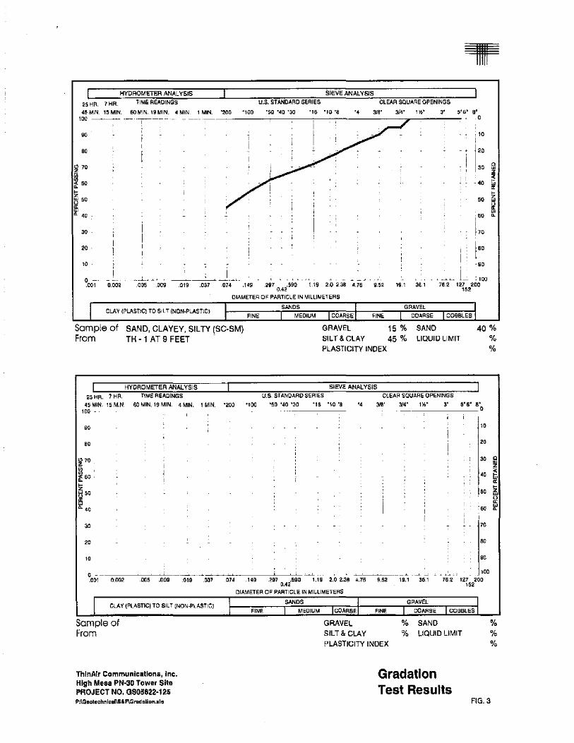
Gradation test results are shown on Figure 3. Laboratory test results are summarized
in Table I.
SITE GEOLOGY
The ge.ology of the site was evaluated using our in-house collection of
geologic maps (Preliminary Geologic Map of the Grand Valley Quadrangle, Garfield
County, Colorado by Donnell, Yeend and Smith, 1986). We interpretthe surficial soils
of the site as pediment gravel deposits underlain by the Wasatch Formation. The
subsurface conditions found In our borings are as expected based on the mapping
we reviewed.
SITE EARTHWORK
Excavations
Based on our subsurface information, excavations for the tower will primarily
encounter silty sand and can be accomplished with conventional, heavy duty
excavation equipment. Excavation sides will need to be sloped or braced to meet
local, state and federal safety regulations, or be retained. The silty sand will likely
classify as a Type C soli based on OSHA standards. Excavations deeper than 4 feet in
Type C soils should be sloped at a 1.5 to 1 (horizontal to vertical) slope. The
THINAIR COMMUNlCA TIONS, INC. HIGH MESA PNJO TOWER SITE PROJECT NO. GS05622-t25 S:\GS05622.000\125\2. Reports\GS05622 125 Rt.doc
3
contractor should identify the soils encountered in excavations and refer to OSHA
standards to determine appropriate slopes. Contractors are responsible to provide
safe and stable exc!ivations. Site safety and maintenance is the contractor's
responsibility.
Free ground water was not found in our exploratory borings on the day of
drilling. We do not anticipate that ground water will significantly impactthe proposed
construction. Excavations should be sloped such that water from precipitation can
drain to a positive gravity outfall or to a temporary sump where water can be removed
by pumping, if necessary.
Backfill
Proper compaction of backfill adjacent to foundations and in utility trenches is
important to reduce subsequent settlement and infiltration of surface water. We
anticipate that excavation backfill will consist of the natural sand. Backfill should be
placed and compacted to reduce settlement. We recommend backfill be placed in ainch thick loose lifts, moisture conditioned to within 2 percent of optimum moisture
content and compacted to at least 95 percent of standard Proctor maximum dry
density (ASTM D 698) to reduce settlement. Particles in excess of 3 Inches in
diameter should be excluded from the backfill soils. Frost or frozen soils should not
be used for backfill. Properly placed fill may settle 'lz to 1 percent of the backfill
thickness. Maintenance of grading In backfill areas may be necessary in the future.
FOUNDATIONS
Our investigation indicates silty sand with sandy clay lenses and occasional
gravel, cobbles and boulders is present at depths likely to influence foundation
performance. The communications tower can be constructed on a mat foundation
constructed on the undisturbed, natural sand and gravel soils. If greater resistance to
overturning due to wind loads is required, micropiles can be drilled below the mat.
The micro piles should be connected to the mat with a bearing plate and nut. Design
THINAIR COMMUNICATIONS, INC. HIGH MESA PN30 TOWER SITE PROJECT NO. GS05622·125 S:\GS05622.000\125\2. Reports\GSD5622125 R1.doc
4
and construction criteria for a mat foundation are presented below. We can provide
recommendations for mlcropiles, If requested.
Mat Foundation
1. The reinforced concrete mat foundation can be constructed on the undisturbed, natural sand and gravel soils.
2. The mat foundation should be designed for a maximum allowable soil pressure of 2,000 psf If constructed on the natural sand and gravel soils.
3. Modulus of subgrade reaction (K,)Is normally used for mat foundation design. The modulus of subgrade reaction is dependent upon the compressibility of the foundation soils and the size (or effective loaded area) ofthe foundation. If the entire mat foundation Is uniformly loaded, then a K. value of 400 pci should be used for the natural sand and gravel soils.
4. To resist lateral loads, a coefficient of friction of 0.40 can be used for concrete In contact with the natural sand and gravel soils. Lateral loads can be resolved by evaluating passive resistance using an equivalent fluid density of 300 pcf for the natural soils, provided the backfill is compacted and is not removed. A moist unit weight of 130 pcf can be assumed for backfill soils. These values have not been factored; appropriate factors of safety should be applied in design.
5. Soil beneath the foundation must be protected from freezing. We recommend the bottom of the foundation be constructed at a depth of at least 36 inches below finished exterior grades. The applicable building department should be consulted regarding required frost depths.
BELOW-GRADE CONSTRUCTION
We understand that no below-grade areas are planned. If construction plans
change, we should be informed so that we can provide below-grade geotechnical
recommendations.
THINAIR COMMUNICATIONS, INC, HIGH MESA PN30 TOWER SITE PROJECT NO. GS05622-125 S:\GS05622.000\125\2, Reports\GS05622 125 R1.doc
5
SURFACE DRAINAGE
Performance of the foundations is influenced by the moisture conditions
existing within the near-surface soils. The risk of wetting foundation soils can be
reduced by properly planned and maintained surface drainage. It is critical that
surface drainage should be designed to provide rapid runoff of water away from the
proposed communications tower. We recommend the following precautions.
1. Wetting or drying of the open foundation excavations should be avoided.
2. Backfill around the foundations should be placed as recommended in the Backfill section. The backfill should be sloped to drain away from the structure in all directions.
CONCRETE
Concrete In contact with soils can be subject to sulfate attack. We measured a
water-soluble sulfate concentration of 0.00 percent in a sample from the site. Sulfate
concentrations less than 0.1 percent indicate Class 0 exposure to sulfate attack for
concrete in contact with the subsoils, according to the American Concrete Institute
(ACI). ACIIndlcates any type of portland cement can be used for concrete that comes
Into contact with the subsoils. In our experience, superficial damage may occur to
the exposed surfaces of highly permeable concrete, even though sulfate levels are
relatively low. To control this risk and to resist freeze-thaw deterioration, the water
to-cementitious material ratio should not exceed 0.50. Concrete should be air
entrained.
DESIGN CONSULTATION AND CONSTRUCTION OBSERVATIONS
This report has been prepared for the exclusive use of ThinAir
Communications, Inc. for the purpose of providing geotechnical criteria for the
proposed project. The information, conclusions and recommendations presented
herein are based upon the considerations of many factors including, but not limited
THINAIR COMMUNICATIONS, INC. HIGH MESA PN30 TOWER SITE PROJECT NO. 0505622·125 S:\G$05622.000\125\2. Reports\0505622125 R1.doc
6
to, the type of structure proposed, the configuration and location of the structure, the
geologic setting, and the subsurface conditions encountered. The conclusions and
recommendations contained in the report are not valid for use by others.
We recommend that CTL 1 Thompson, Inc. be retained to provide general
review of the final construction plans prior to construction. Our firm should also
provide geotechnical and materials testing during construction. The purpose is to
observe the construction with respect to the geotechnical design concepts,
specifications or recommendations, and to facilitate design changes in areas where
the subsurface conditions differ from those anticipated prior to start of construction.
GEOTECHNICAL RISK
The concept of risk is an Important aspect ofany geotechnical evaluation. The
primary reason for this is that the analytical methods used to develop geotechnical
recommendations do not comprise an exact science. The analytical tools which
geotechnical engineers use are generally empirical and must be tempered by
engineering judgment and experience. Therefore, the solutions or recommendations
presented in any geotechnical evaluation should not be considered risk-free and,
more importantly, are not a guarantee that the interaction between the soils and the
proposed structures will perform as desired or intended. What the engineering
recommendations presented in the preceding sections do constitute is our judgment
of those measures that are necessary to increase changes that the project will
perform satisfactorily. The owner must understand this concept of risk, as it is they
who must decide what is an acceptable level of risk.
LIMITATIONS
We drilled our borings near the proposed tower site to obtain a reasonably
accurate picture of subsurface conditions. Variations in the subsurface conditions
not indicated by our borings are possible. Fill placement and compaction should be
THINAIR COMMUNICATIONS. INC. HIGH MESA PN30 TOWER SITE PROJECT NO. GS05622·125 S:\GS05622.000\125\2. Reports\GS05622 125 R1.doc
7
observed and tested by a representative of our firm during construction. We should
observe the foundation excavation prior to concrete placement.
We believe this investigation was conducted with that level of skill and care
ordinarily used by geotechnical engineers practicing in this area at this time. No
warranty, express or implied, is made. If we can be offurther service in discussing the
contents ofthis report, or in the analysis of the influence of the subsurface conditions
on the design of the structure, please call.
cc: Via Email to [email protected]
THIN AIR COMMUNICATIONS, INC, HIGH MESA PN30 TOWER SITE PROJECT NO. GS05622·125 S:IGS05622.000\12512. Reports\GS05622125 R1.doc
8
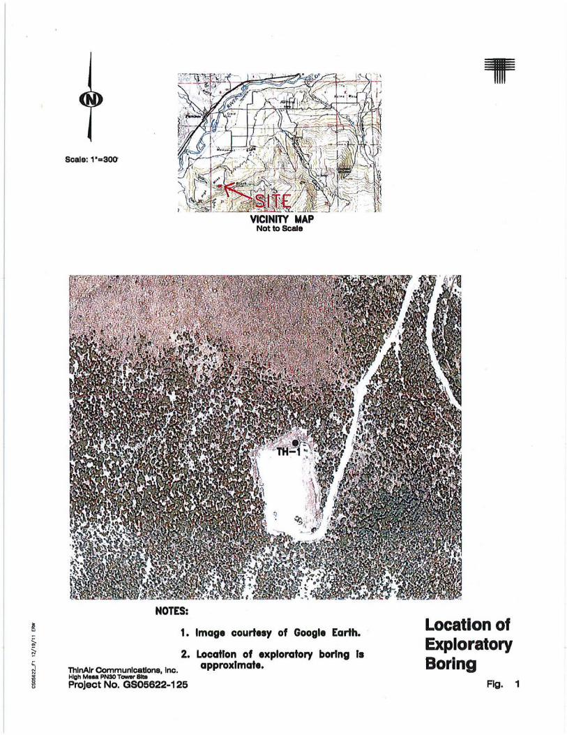
Scale: 1"=300'
VICINITY MAP Notto8cale
1. Image courtesy of Google Earth.
2. Location of exploratory boring Is ThlnAlr CommunlcaUons Inc approximate. High Meea PN30 Tower 81t11 ' '
Project No. GS05622-125
Location of Exploratory Boring
Fig. 1
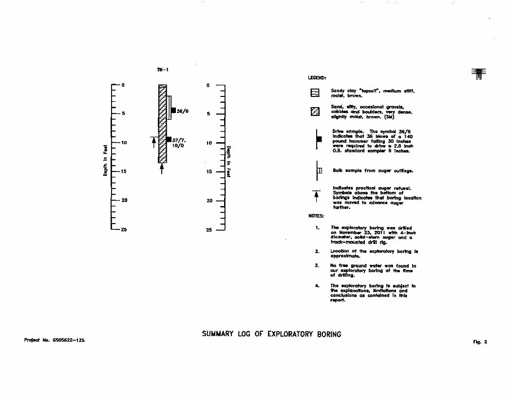
SUMt.lARY LOG OF EXPLORATORY BORING ProJect No. GS05622-125 Fig. 2
HYDROMETER ANALYSIS SIEVE ANALYSIS
25 HR. 7 HR.
45 MIN. 15 MIN. 100-.---
90
80
30 .
20 .
10 .
0 .001 0.002
TIME READINGS U.S. STANDARD SERIES CLEAR SQUARE OPENINGS
60MIN.I9MIN. 4MIN. 1 MIN. '200 '100 '50 '40 '30 '16 '10 '8 '4 318' 3/4' 11-!1' 3' 5'6' B' ·-! --~-- -, ----.,.----.,----c----,--,-.,---,----,--~-.,..---;--- 0
10
20
30
• 40
50
l ;50 I
170
-~ ............... --~---·~~ • ..J..J.. ~ _j_ -'--'--'---'----'-'-- _.._ ~ _._~~---
i I BO
I • 90
j_ ~ 100
.005 .009 .019 .037 .074 .149 .297 .590 1.19 2.0 2.38 4.76 9.52 0.42
19.1 36.1 76.2 127 200 152
CLAY (PLASTIC) TO SILT (NON-PLASTIC)
DIAMETER OF PARTICLE IN MILLIMETERS
SANDS
FINE MEDIUM COARSE
GRAVEL
FINE COARSE COBBLES
0 w z
~ ~ ~ z w if w ~
Sample of From
SAND, CLAYEY, SILTY (SC-SM) TH • 1 AT 9 FEET .
GRAVEL 15% SILT & CLAY 45% PLASTICITY INDEX
SAND LIQUID LIMIT
40% % %
HYDROMETER ANALYSIS SIEVE ANALYSIS
25 HR. 7HR. TIME READINGS U.S. STANDARD SERIES CLEAR SQUARE OPENINGS
45MIN. 15M.N. 60 MIN. 19 MIN. 4MIN. 1 MIN. '200 '100 ·so '40 '30 '16 ·,o ·a '4 319' ~··
1W 3' 5'6' 8' 100 0
90 10
90 20
~ 70 30 0 w 00 ~ 00 40 ~ 60.
~ ~
i 50 ~ z z
~so w
" "' ~ 40 50 w ~
I
30 70
20 90
10 90
0 • -~~-- 100
.001 0.002 .005 .009 .019 .037 .074 .149 .297 .590 1.19 2.0 2.38 4.76 9.52 19.1 36.1 76.2 127 200 0.42 152
DIAMETER OF PARTICLE IN MILLIMETERS
CLAY (PLASTIC) TO SILT (NON-PLASTICI SANDS GRAVEL
FINE MEDIUM COARSE FINE COARSE COBBLES
Sample of GRAVEL % SAND % From SILT & CLAY % LIQUID LIMIT %
PLASTICITY INDEX %
ThlnAir Communications, Inc. Gradation High Mesa PN-30 Tower Site
Test Results PROJECT NO. GSD5622·125 P:\Geotechnicei\S&F\Gradellan.xla FIG. 3
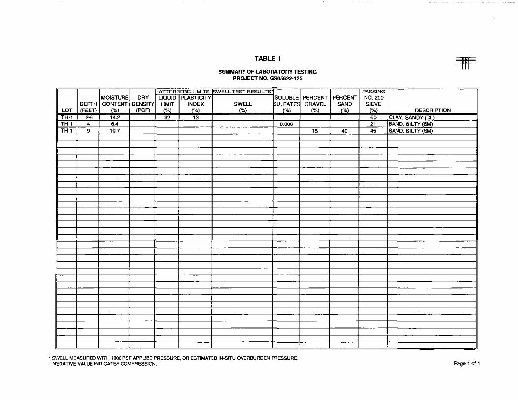
MOISTURE DRY DEPTH CONTENT DENSITY
LOT (FEET) (%) (PC F)
TH-1 2-6 14.2 TH-1 4 6.4 TH-1 9 10.7
ATTERBERG LIMITS LIQUID PLASTICITY LIMIT INDEX (%) (%) 32 13
TABLE I
SUMMARY OF LABORATORY TESTING PROJECT NO. GS05622-125
-SWELL TEST RESULTS
SOLUBLE PERCENT SWELL ~ULFATE~ GRAVEL
(%) (%) (%)
0.000 15
• SWELL MEASURED WITH 1000 PSF APPLIED PRESSURE, OR ESTIMATED IN-51TU OVERBURDEN PRESSURE. NEGATIVE VALUE INDICATES COMPRESSION.
T ----
PASSING PERCENT N0.200
SAND SIEVE (%) (%) DESCRIPTION
60 CLAY, SANDY (CL) 21 SAND, SILTY (SM)
40 45 SAND, SILTY (SM)
Page 1 of 1
\
n w
~ ~UJO:::> ~ ~
0\oLSSON ASSOCIATES
January 25, 2011
Molly Orkild-Larson, Senior Planner Garfield County Building and Planning Department 108 81
h Street, #401 Glenwood Springs, CO 81601
---
RE: Completeness Review Daybreak Realty LLP- Encana Oil and Gas (USA) Inc. Communication Facility (File LIPA -7054)
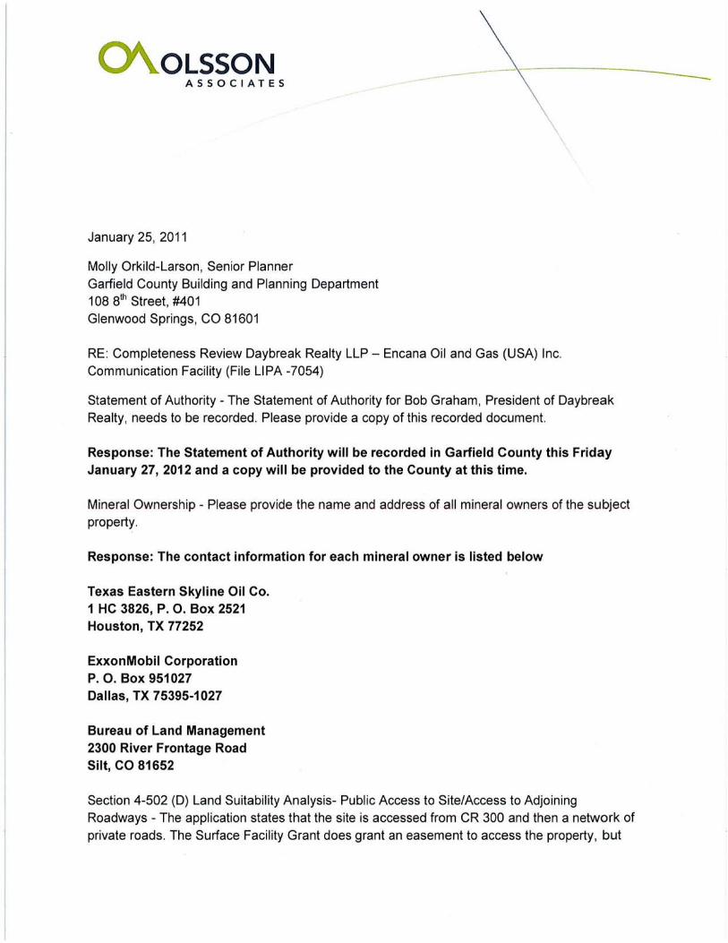
Statement of Authority- The Statement of Authority for Bob Graham, President of Daybreak Realty, needs to be recorded. Please provide a copy of this recorded document.
Response: The Statement of Authority will be recorded in Garfield County this Friday January 27, 2012 and a copy will be provided to the County at this time.
Mineral Ownership- Please provide the name and address of all mineral owners of the subject property.
Response: The contact information for each mineral owner is listed below
Texas Eastern Skyline Oil Co. 1 HC 3826, P. 0. Box 2521 Houston, TX 77252
ExxonMobil Corporation P. 0 . Box 951027 Dallas, TX 75395-1027
Bureau of Land Management 2300 River Frontage Road Silt, CO 81652
Section 4-502 (D) Land Suitability Analysis- Public Access to Site/Access to Adjoining Roadways - The application states that the site is accessed from CR 300 and then a network of private roads. The Surface Facility Grant does grant an easement to access the property, but
based on the vicinity map it does not appear that access is through the parcel owned by Daybreak Realty. What parcels does the private road cross between CR 300 and the site? And what legal right does EnCana have to use these roads? Please provide documentation thrt
demonstrates legal access to the subject parcel.
Response Pending
Section 7-823 Additional Standards Applicable to Telecommunication Facilities Structural and Engineering Standards. Submit evidence from a qualified professional engineer licensed by the State of Colorado verifying that structural and engineering standards of the proposed communication facility are adequate.
Response: Attached to this document is a copy of the Construction Drawings and Geotechnical and Soils Report prepared by Professional Engineers.
Federal Aviation Agency (FAA) Form. From reviewing your application it appears that the proposed communication facility does not need FAA approval since the tower's height is less than 200 feet and is located more than five miles from an airport. Is this correct? The band width wasn't specified in the application but from the narrative I'm assuming that FCC regulations do not apply since the tower radio frequency operates within a band width that doesn't require licensing. To verify this assumption please indicate what frequency this facility will be operating
at.
Response: SCADA radio traffic will operate in the 900Mhz band, and the corporate network radio traffic will operate in the licensed 11 Ghz frequency band. Attached to this document is a copy of the FAA Noticing requirement demonstrating that additional FAA permits will not be required for this proposal.
Please review at your earliest convenience and contact me for further questions. Thank you Sincerely
Grant C. Griffin Project Scientist Olsson Associates [email protected] TEL: 970-263-7800
CC: Renata Busch, Encana Oil and Gas (USA) Inc. Permitting/South Rockies Construction Lorne Prescott, Olsson Associates Senior Project Scientist
December 2, 2011
Attention: Grant Griffin Olsson Associates 826 21 Y2 Road Grand Junction, CO 81505
Garfield County BUILDING & PLANNING DEPARTMENT
RE: Daybreak Realty LLC - High Mesa PN-30 Communication Facility (LIPA 7038)
Dear Grant,
I am writing this letter regarding the Daybreak Realty LLC - High Mesa PN-30 Communication Facility application for Limited Impact Review for a Communication Facil ity. At th is time the application does not include all required information per Garfield County Regulations. The application is therefore deemed technically incomplete and the Planning Department will not process this application any further until the following information, listed below, has been provided to the satisfaction of this office. Please address the following items and submit three copies of the modified information to this office so that we may continue the review of this application:
ULUR 4-502 Description of Submittal Requirements (for Limited Impact Review) To meet the ULUR requirements for the Site Plan include the following:
General Submittal Requirements Statement of Authority
• The Statement of Authority for Bob Graham, President of Daybreak Realty, needs to be recorded. Please provide a copy of this recorded document.
Mineral Ownership • Please provide the name and address of all mineral owners of the subject property.
Section 4-502 (D) Land Suitability Analysis Public Access to Site/Access to Adjoining Roadways - The application states that the site is accessed from CR 300 and then a network of private roads. The Surface Facility Grant does grant an easement to access the property, but based on the vicinity map it does not appear that access is through the parcel owned by Daybreak Realty. What parcels does the private road cross between CR 300 and the site? And what legal right does EnCana have to use these roads? Please provide documentation that demonstrates legal access to the subject parcel.
Section 7-823 Additional Standards Applicable to Telecommunication Facilities C. Structural and Engineering Standards. Submit evidence from a qualified professional
0375 County Road 352, Building #2060 • Rifle, CO 81650 (970) 625-5900 • Fax: (970) 625-5939
108 Eighth Street, Suite 401 • Glenwood Springs, CO 81601 (970) 945-8212 • Fax: (970) 384-3470
engineer licensed by the State of Colorado verifying that structural and engineering standards of the proposed communication facility are adequate.
0. Federal Aviation Agency (FAA) Form. From reviewing your application it appears that the proposed communication facility does not need FAA approval since the tower's height is less than 200 feet and is located more than five miles from an airport. Is this correct?
The band width wasn 't specified in the application but from the narrative I'm assuming that FCC regulations do not apply since the tower radio frequency operates within a band width that doesn't require licensing. To verify this assumption please indicate what frequency this facility will be operating at.
Please note, as per Section 4-103 (C) (1 }, if the application is not complete, the Director shall inform the applicant of the deficiencies in writing and shall take no further action on the application until the deficiencies are remedied. If the applicant fails to correct the deficiencies within sixty (60) calendar days which ends January 31, 2012, the application shall be considered withdrawn and returned to the applicant.
Sincerely,
MOiiYC)fkii:Larson, AICP, RLA Senior Planner
970-625-5903
2
Federal Communications Commission- Wikipedia, the free encyclopedia Page 1 of2
Offices
The FCC's Offices provide support services to the Bureaus. Though the Bureaus and Offices have their individual functions, they regularly work together on FCC issues.
• The Office of Administrative Law Judges (OALJ) is responsible for conducting hearings ordered by the Commission. The hearing function includes acting on interlocutory requests filed in the proceedings such as petitions to intervene, petitions to enlarge issues, and contested discovery requests. An Administrative Law Judge, appointed under the Administrative Procedure Act, presides at the hearing during which documents and sworn testimony are received in evidence, and witnesses are cross-examined. At the conclusion of the evidentiary phase of a proceeding, the presiding Administrative Law Judge writes and issues an Initial Decision which may be appealed to the Commission.
• The Office of Communications Business Opportunities (OCBO) promotes telecommunications business opportunities for small, minority-owned, and women-owned businesses. OCBO works with entrepreneurs, industry, public interest organizations, individuals, and others to provide information about FCC policies, increase ownership and employment opportunities, foster a diversity of voices and viewpoints over the airwaves, and encourage participation in FCC proceedings.
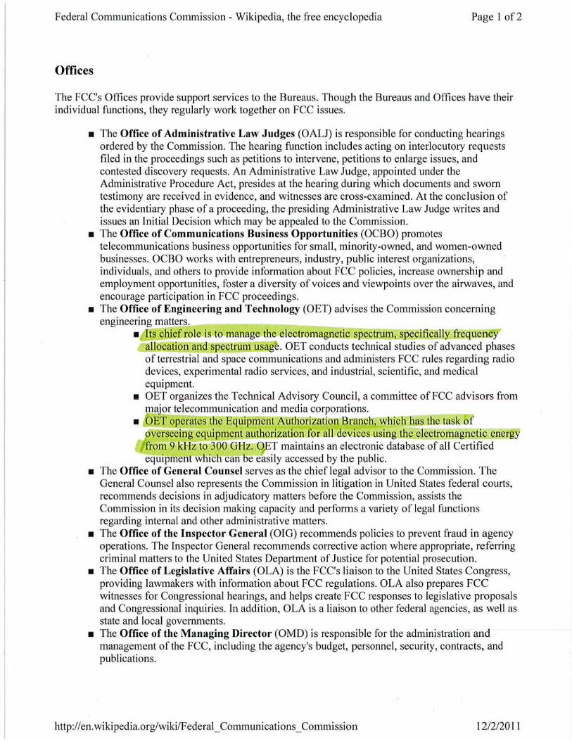
• The Office of Engineering and Technology (OET) advises the Commission concerning engineering matters.
• ts chief role is to manage the electromagnetic spectrum, specifically frequency allocation and spectrum usag . OET conducts technical studies of advanced phases of terrestrial and space communications and administers FCC rules regarding radio devices, experimental radio services, and industrial, scientific, and medical equipment.
• OET organizes the Technical Advisory Council, a committee of FCC advisors from major telecommunication and media corporations.
• OET operates the Equipment Authorization Branch, which has the task of overseeing equipment authorizationior all devices using the electromagnetic energy from 9 KHz to-300 GHz. O,.ET maintains an electronic database of all Certified equipment which can be easily accessed by the public.
• The Office of General Counsel serves as the chief legal advisor to the Commission. The General Counsel also represents the Commission in litigation in United States federal courts, recommends decisions in adjudicatory matters before the Commission, assists the Commission in its decision making capacity and performs a variety of legal functions regarding internal and other administrative matters. ·
• The Office of the Inspector General (010) recommends policies to prevent fraud in agency operations. The Inspector General recommends corrective action where appropriate, referring criminal matters to the United States Department of Justice for potential prosecution.
• The Office of Legislative Affairs (OLA) is the FCC's liaison to the United States Congress, providing lawmakers with information about FCC regulations. OLA also prepares FCC witnesses for Congressional hearings, and helps create FCC responses to legislative proposals and Congressional inquiries. In addition, OLA is a liaison to other federal agencies, as well as state and local governments.
• The Office of the Managing Director (OMD) is responsible for the administration and management of the FCC, including the agency's budget, personnel, security, contracts, and publications.
http: //en. wikipedia.org/wiki/Federal_ Communications_ Commission 12/2/2011
Federal Communications Commission- Wikipedia, the free encyclopedia Page 2 of2
• The Office of Media Relations (OMR) is responsible for the dissemination of Commission announcements, orders, proceedings, and other information per media requests. OMR manages the FCC Daily Digest, website, and Audio Visual Center.
• The Office of the Secretary (OSEC) oversees the receipt and distribution of documents filed by the public through electronic and paper filing systems and the FCC Library collection. In addition, OSEC publishes legal notices of Commission decisions in the Federal Register and the FCC Record.
• The Office of Strategic Planning & Policy Analysis (OSP), essentially a think tank within the FCC, identifies policy objectives for the agency. OSP works closely with the FCC Chairman and is responsible for monitoring the state ofthe communications industry to identify trends, issues and overall industry health. OSP acts as expert consultants to the Commission in areas of economic, business, and market analysis. The Office also reviews legal trends and developments not necessarily related to current FCC proceedings, such as intellectual property law, the Internet, and electronic commerce. Previously OSP was called the Office of Plans and Policy (OPP). Catherine Bohigian has been the chief of the OSP since 2005J8l
• The Office of Workplace Diversity (OWD) develops policy to provide a full and fair opportunity for all employees, regardless of non-merit factors such as race, religion, gender, color, age, disability, sexual orientation or national origin, to carry out their duties in the workplace free from unlawful discriminatory treatment, including sexual harassment and retaliation for engaging in legally protected activities.
http://en. wikipedia.org/wiki/F ederal_ Communications_ Commission 12/2/2011
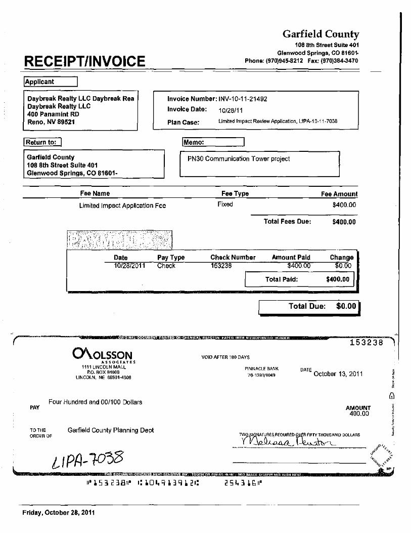
(
RECEIPT/INVOICE !Applicant
Daybreak Realty LLC Daybreak Rea Daybreak Realty LLC 400 Panamint RD Reno, NV 89521
I Return to: I Garfield County 108 8th Street Suite 401 Glenwood Springs, CO 81601-
Fee Name
Garfield County 108 8th Street Suite 401
Glenwood Springs, CO 81601-Phone: (970)945-8212 Fax: (970)384-3470
Invoice Number: INV-1 0-11-21492
Invoice Date: 10/28/11
Plan Case: Limited Impact Review Application, LIPA-1 0-11-7038
I Memo:
PN30 Communication Tower project
Fee Type Fee Amount
Limited Impact Application Fee Fixed $400.00
Date 10/28/2011
Pay Type Check
Check Number 153238
Total Fees Due:
Amount Paid $400.00
Total Paid:
$400.00
Change $0.00
$400.00 1
Total Due: $0.00 I
of;!iolh't.! lij o!U3 II I Iii 'i j!lil·llliil'loio!, IOJ#!#! I !!of·l"l ;J#i.jij 1\9 :a i/.1ij'!l •b\ Ill I I t@ •lo@ih U:!J i:IWU I§!·
153238 ~"l 0\oLSSON
ASSOCIATES 1111 LINCOLN MALL
P.O. BOX 84608 LINCOLN, NE 68501·4608
Four Hundred and 00/100 Dollars PAY
TO THE ORDER OF
Garfield County Planning Dept
VOID AFTER 180 DAYS
PINNACLE BANK
76-1391/1049 DATE
October 13, 2011
AMOUNT 400.00
~~~DDOLLARS
@O-J o!oiO(i!l @I 110(•1 IU.! 1/!.'Jl!i'f.! iJili!/j;::ji U'jilii!:Mio!IIOJ: Mo!-lij·!ijf!Oil@·i:W·i i! oli \!.13 ::W o!!Wi!\1#1·\i!. ..... !li! I mt.1
Friday, October 28, 2011