Embed Size (px)
Citation preview
ITEM 664.84000010 – SANITARY SEWER PUMPING STATION
Page 1 of 24 March 2016
DESCRIPTION
The work shall consist of providing a sanitary pumping station complete with submersible
pumps; flow meter; piping; fittings; valves and specials; hatches; control enclosure; pump
controls; alarm system, remote alarm equipment; all required instrumentation and control
equipment for a sanitary sewer pump station including, but not limited to, a fully functional
electric motor(s) (including all required parts and accessories to drive the explosion proof
blower), an explosion proof blower to provide ventilation to the wet well during use, explosion
proof lighting to provide illumination inside of the wet well during use, and explosion proof
switches for the activation of the blower and lights in the wet well and valve vault, and all
appurtenances in accordance with Plans and Specifications or as directed or as approved by the
Engineer. The Contractor shall provide all labor, materials and equipment for a complete
installation and a ready for operation sanitary sewer pumping station.
MATERIALS
1. General:
All materials and appurtenances required for the work shall be new and of quality matching that
specified herein. Where no specific kind or quality of material is given, a first class standard
article as accepted by the Engineer shall be furnished.
2. Sanitary Pump Wet Well and Valve Chamber:
a. Bedding Material: Bedding material for the wet well shall be crushed stone meeting the
requirements of Material Designation 703-0201 of the NYSDOT Standard Specifications
and/or as directed or as approved by the Engineer.
b. Structures: The wet well and valve chamber shall be of pre-cast reinforced concrete
construction meeting the requirements of Subsection 704-03 “Precast Concrete –
General” of the NYSDOT Standard Specifications, except as noted herein. Precast
concrete shall attain a minimum 28-day compression strength of 3,000 PSI. The
Engineer reserves the right to reject any pre-cast units that show evidence of poor
workmanship or subsequent damage. All tie wires, spreaders, conduit openings, etc.,
shall be cut back at openings, at least two (2) inches then repaired in accordance with
Subsection 704-03. The manufacturer shall comply with all recommendations of the
waterproofing company so as to produce a completely waterproof structure. The Precast
Sanitary Pump Wet Well and Valve Chamber shall be manufactured by:
Coastal Pipeline Products Corp.
Calverton, NY 11933
Long Island Precast, Inc.
Brookhaven, NY 11719
Old Castle Precast Inc.
Middle Island, NY 11953
Or equal, as directed or as approved by the Engineer.
Wall thickness, floor thickness, together with length, width and height of the pump
station shall be as shown on the Drawings. If shown on the Drawings, a counter flotation
ring of concrete shall be poured in place. Joints shall be made with flexible gaskets
conforming to ASTM C361.
c. Access Hatches: Heavy Duty with Safety Grate: Where shown on the Contract
Drawings, an access hatch shall be furnished and installed on the wet well and valve
chamber structure top slabs. The access hatch shall be constructed of 1/4 inch aluminum
channel frame with an anchor flange around the perimeter. The access door shall be
ITEM 664.84000010 – SANITARY SEWER PUMPING STATION
Page 2 of 24 March 2016
1/4 inch aluminum diamond shape pattern designed and constructed to withstand a live
load of 300 pounds per square foot and shall be equipped with stainless steel hardware
throughout and automatic hold open arm(s) with release handle. A snap lock with a
removable handle with a recessed hasp covered by a hinged lid flush with surface shall be
provided. A bituminous coating shall be applied to the exterior of the frame. A
1-1/2 inch drainage coupling shall be located in the front right corner of channel frame.
The device shall be provided with an 8-inch minimum curb. An integral powder coated
aluminum safety grate with hinged mechanism shall also be included. When closed, the
grate shall conform with OSHA 1910.23 for fall protection. The access hatches shall be
manufactured by:
EJ Group,
Cicero, NY 13039
Nystrom Building Products,
Minneapolis, MN 55428
Halliday Products Inc.
Orlando, FL 32810
Or equal, as directed or as approved by the Engineer.
d. Piping, Fittings, Valves and Specials, Etc.: The Contractor shall furnish and install all
necessary piping, fittings, valves and specials, etc. at the pump station, as required and as
shown on the Drawings.
1) Plug Valve, 4 Inches and Larger:
a) Valves shall be non-lubricated, tapered type.
b) Type: Cast iron body.
c) Plug: Drip-tight, steel with resilient facing bonded to sealing surface and suitable
for sewage application.
d) Packing: Nitrile-Butadiene.
e) Bearings: Heavy duty stainless steel.
f) Pressures: Working Pressure: 125 psi Cold Working Pressure (CWP).
g) Flanged Joint: ANSI B16.1; Class 125, 250 psi working pressure minimum.
h) Coatings: All internal surfaces, except finished surfaces, gaskets, or bearing
surfaces shall be epoxy coated in accordance with AWWA C550.
i) Eccentric plug valves shall conform to current AWWA standards and shall be
opened and closed with wheel operators. The eccentric plug valves shall be
manufactured by:
Kennedy Valve Co.
Elmira, NY 14901
Henry Pratt Co.
Aurora, IL 60506
DeZurik / APCO / Hilton
Sartell, MN 56377
Or equal, as directed or as approved by the Engineer.
2) Check Valves: Check valves shall be a non-clog, unobstructed, free flow rolling ball
type. The ball shall be out of the flow in the open position and be directed to and
from the body seat by guiderails integral with the valve body. The ball shall be
actuated by the flowing medium, without the use of springs, levers, weights, etc. The
body shall be flanged, cast iron and the ball shall be a hollow steel sphere with a
smooth covering of nitrile rubber. The valve shall be suitable for 1030 kPa (150 psi)
working pressure. Flanges shall be flat faced and drilled to ANSI B16.1, Class 125
cast iron. The check valve shall be manufactured by:
ITT Flygt Corp.
Trumble, CT 06611
Clow Valve Co.
Oskaloosa, IA 52577
Kennedy Valve Co.
Elmira, NY 14901
ITEM 664.84000010 – SANITARY SEWER PUMPING STATION
Page 3 of 24 March 2016
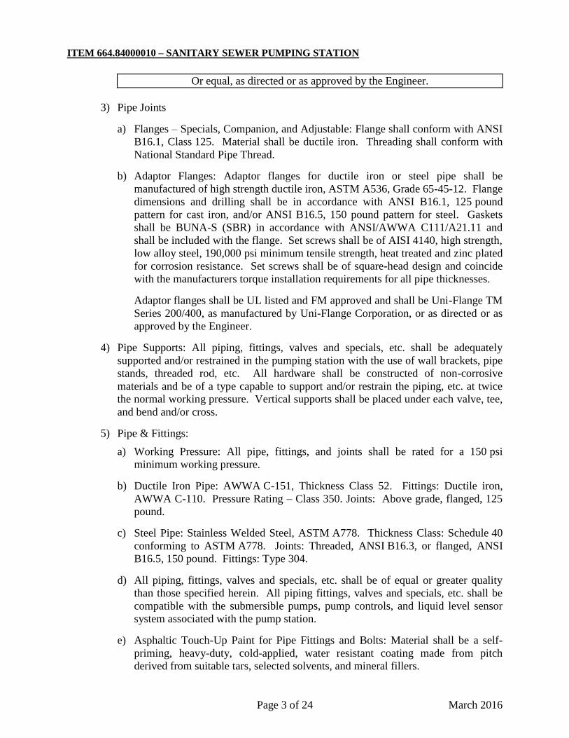
Or equal, as directed or as approved by the Engineer.
3) Pipe Joints
a) Flanges – Specials, Companion, and Adjustable: Flange shall conform with ANSI
B16.1, Class 125. Material shall be ductile iron. Threading shall conform with
National Standard Pipe Thread.
b) Adaptor Flanges: Adaptor flanges for ductile iron or steel pipe shall be
manufactured of high strength ductile iron, ASTM A536, Grade 65-45-12. Flange
dimensions and drilling shall be in accordance with ANSI B16.1, 125 pound
pattern for cast iron, and/or ANSI B16.5, 150 pound pattern for steel. Gaskets
shall be BUNA-S (SBR) in accordance with ANSI/AWWA C111/A21.11 and
shall be included with the flange. Set screws shall be of AISI 4140, high strength,
low alloy steel, 190,000 psi minimum tensile strength, heat treated and zinc plated
for corrosion resistance. Set screws shall be of square-head design and coincide
with the manufacturers torque installation requirements for all pipe thicknesses.
Adaptor flanges shall be UL listed and FM approved and shall be Uni-Flange TM
Series 200/400, as manufactured by Uni-Flange Corporation, or as directed or as
approved by the Engineer.
4) Pipe Supports: All piping, fittings, valves and specials, etc. shall be adequately
supported and/or restrained in the pumping station with the use of wall brackets, pipe
stands, threaded rod, etc. All hardware shall be constructed of non-corrosive
materials and be of a type capable to support and/or restrain the piping, etc. at twice
the normal working pressure. Vertical supports shall be placed under each valve, tee,
and bend and/or cross.
5) Pipe & Fittings:
a) Working Pressure: All pipe, fittings, and joints shall be rated for a 150 psi
minimum working pressure.
b) Ductile Iron Pipe: AWWA C-151, Thickness Class 52. Fittings: Ductile iron,
AWWA C-110. Pressure Rating – Class 350. Joints: Above grade, flanged, 125
pound.
c) Steel Pipe: Stainless Welded Steel, ASTM A778. Thickness Class: Schedule 40
conforming to ASTM A778. Joints: Threaded, ANSI B16.3, or flanged, ANSI
B16.5, 150 pound. Fittings: Type 304.
d) All piping, fittings, valves and specials, etc. shall be of equal or greater quality
than those specified herein. All piping fittings, valves and specials, etc. shall be
compatible with the submersible pumps, pump controls, and liquid level sensor
system associated with the pump station.
e) Asphaltic Touch-Up Paint for Pipe Fittings and Bolts: Material shall be a self-
priming, heavy-duty, cold-applied, water resistant coating made from pitch
derived from suitable tars, selected solvents, and mineral fillers.
ITEM 664.84000010 – SANITARY SEWER PUMPING STATION
Page 4 of 24 March 2016
e. Slide Rail System: A corrosion resistant slide rail base complete with lower guide bar,
holder, discharge elbow, and hydraulic sealing flange shall be bolted to the floor of the
pump chamber with stainless steel bolts. Each slide rail shall be sized per pump
manufacturer’s recommendations and shall be anchored to the wet wall with stainless steel
anchors at 10 feet maximum intervals to prevent deflection. All mounting brackets and
hardware shall be stainless steel.
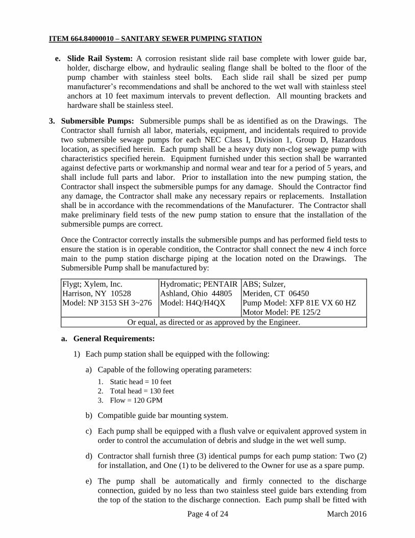
3. Submersible Pumps: Submersible pumps shall be as identified as on the Drawings. The
Contractor shall furnish all labor, materials, equipment, and incidentals required to provide
two submersible sewage pumps for each NEC Class I, Division 1, Group D, Hazardous
location, as specified herein. Each pump shall be a heavy duty non-clog sewage pump with
characteristics specified herein. Equipment furnished under this section shall be warranted
against defective parts or workmanship and normal wear and tear for a period of 5 years, and
shall include full parts and labor. Prior to installation into the new pumping station, the
Contractor shall inspect the submersible pumps for any damage. Should the Contractor find
any damage, the Contractor shall make any necessary repairs or replacements. Installation
shall be in accordance with the recommendations of the Manufacturer. The Contractor shall
make preliminary field tests of the new pump station to ensure that the installation of the
submersible pumps are correct.
Once the Contractor correctly installs the submersible pumps and has performed field tests to
ensure the station is in operable condition, the Contractor shall connect the new 4 inch force
main to the pump station discharge piping at the location noted on the Drawings. The
Submersible Pump shall be manufactured by:
Flygt; Xylem, Inc.
Harrison, NY 10528
Model: NP 3153 SH 3~276
Hydromatic; PENTAIR
Ashland, Ohio 44805
Model: H4Q/H4QX
ABS; Sulzer,
Meriden, CT 06450
Pump Model: XFP 81E VX 60 HZ
Motor Model: PE 125/2
Or equal, as directed or as approved by the Engineer.
a. General Requirements:
1) Each pump station shall be equipped with the following:
a) Capable of the following operating parameters:
1. Static head = 10 feet
2. Total head = 130 feet
3. Flow = 120 GPM
b) Compatible guide bar mounting system.
c) Each pump shall be equipped with a flush valve or equivalent approved system in
order to control the accumulation of debris and sludge in the wet well sump.
d) Contractor shall furnish three (3) identical pumps for each pump station: Two (2)
for installation, and One (1) to be delivered to the Owner for use as a spare pump.
e) The pump shall be automatically and firmly connected to the discharge
connection, guided by no less than two stainless steel guide bars extending from
the top of the station to the discharge connection. Each pump shall be fitted with
ITEM 664.84000010 – SANITARY SEWER PUMPING STATION
Page 5 of 24 March 2016
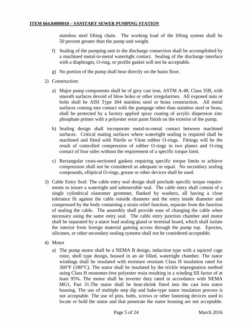
stainless steel lifting chain. The working load of the lifting system shall be
50 percent greater than the pump unit weight.
f) Sealing of the pumping unit to the discharge connection shall be accomplished by
a machined metal-to-metal watertight contact. Sealing of the discharge interface
with a diaphragm, O-ring, or profile gasket will not be acceptable.
g) No portion of the pump shall bear directly on the basin floor.
2) Construction:
a) Major pump components shall be of grey cast iron, ASTM A-48, Class 35B, with
smooth surfaces devoid of blow holes or other irregularities. All exposed nuts or
bolts shall be AISI Type 304 stainless steel or brass construction. All metal
surfaces coming into contact with the pumpage other than stainless steel or brass,
shall be protected by a factory applied spray coating of acrylic dispersion zinc
phosphate primer with a polyester resin paint finish on the exterior of the pump.
b) Sealing design shall incorporate metal-to-metal contact between machined
surfaces. Critical mating surfaces where watertight sealing is required shall be
machined and fitted with Nitrile or Viton rubber O-rings. Fittings will be the
result of controlled compression of rubber O-rings in two planes and O-ring
contact of four sides without the requirement of a specific torque limit.
c) Rectangular cross-sectioned gaskets requiring specific torque limits to achieve
compression shall not be considered as adequate or equal. No secondary sealing
compounds, elliptical O-rings, grease or other devices shall be used.
3) Cable Entry Seal: The cable entry seal design shall preclude specific torque require-
ments to insure a watertight and submersible seal. The cable entry shall consist of a
single cylindrical elastomer grommet, flanked by washers, all having a close
tolerance fit against the cable outside diameter and the entry inside diameter and
compressed by the body containing a strain relief function, separate from the function
of sealing the cable. The assembly shall provide ease of changing the cable when
necessary using the same entry seal. The cable entry junction chamber and motor
shall be separated by a stator lead sealing gland or terminal board, which shall isolate
the interior from foreign material gaining access through the pump top. Epoxies,
silicones, or other secondary sealing systems shall not be considered acceptable.
4) Motor
a) The pump motor shall be a NEMA B design, induction type with a squirrel cage
rotor, shell type design, housed in an air filled, watertight chamber. The stator
windings shall be insulated with moisture resistant Class H insulation rated for
360°F (180°C). The stator shall be insulated by the trickle impregnation method
using Class H monomer-free polyester resin resulting in a winding fill factor of at
least 95%. The motor shall be inverter duty rated in accordance with NEMA
MG1, Part 31.The stator shall be heat-shrink fitted into the cast iron stator
housing. The use of multiple step dip and bake-type stator insulation process is
not acceptable. The use of pins, bolts, screws or other fastening devices used to
locate or hold the stator and that penetrate the stator housing are not acceptable.
ITEM 664.84000010 – SANITARY SEWER PUMPING STATION
Page 6 of 24 March 2016
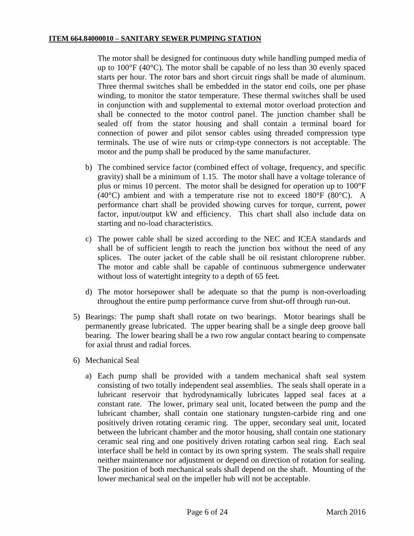
The motor shall be designed for continuous duty while handling pumped media of
up to 100°F (40°C). The motor shall be capable of no less than 30 evenly spaced
starts per hour. The rotor bars and short circuit rings shall be made of aluminum.
Three thermal switches shall be embedded in the stator end coils, one per phase
winding, to monitor the stator temperature. These thermal switches shall be used
in conjunction with and supplemental to external motor overload protection and
shall be connected to the motor control panel. The junction chamber shall be
sealed off from the stator housing and shall contain a terminal board for
connection of power and pilot sensor cables using threaded compression type
terminals. The use of wire nuts or crimp-type connectors is not acceptable. The
motor and the pump shall be produced by the same manufacturer.
b) The combined service factor (combined effect of voltage, frequency, and specific
gravity) shall be a minimum of 1.15. The motor shall have a voltage tolerance of
plus or minus 10 percent. The motor shall be designed for operation up to 100°F
(40°C) ambient and with a temperature rise not to exceed 180°F (80°C). A
performance chart shall be provided showing curves for torque, current, power
factor, input/output kW and efficiency. This chart shall also include data on
starting and no-load characteristics.
c) The power cable shall be sized according to the NEC and ICEA standards and
shall be of sufficient length to reach the junction box without the need of any
splices. The outer jacket of the cable shall be oil resistant chloroprene rubber.
The motor and cable shall be capable of continuous submergence underwater
without loss of watertight integrity to a depth of 65 feet.
d) The motor horsepower shall be adequate so that the pump is non-overloading
throughout the entire pump performance curve from shut-off through run-out.
5) Bearings: The pump shaft shall rotate on two bearings. Motor bearings shall be
permanently grease lubricated. The upper bearing shall be a single deep groove ball
bearing. The lower bearing shall be a two row angular contact bearing to compensate
for axial thrust and radial forces.
6) Mechanical Seal
a) Each pump shall be provided with a tandem mechanical shaft seal system
consisting of two totally independent seal assemblies. The seals shall operate in a
lubricant reservoir that hydrodynamically lubricates lapped seal faces at a
constant rate. The lower, primary seal unit, located between the pump and the
lubricant chamber, shall contain one stationary tungsten-carbide ring and one
positively driven rotating ceramic ring. The upper, secondary seal unit, located
between the lubricant chamber and the motor housing, shall contain one stationary
ceramic seal ring and one positively driven rotating carbon seal ring. Each seal
interface shall be held in contact by its own spring system. The seals shall require
neither maintenance nor adjustment or depend on direction of rotation for sealing.
The position of both mechanical seals shall depend on the shaft. Mounting of the
lower mechanical seal on the impeller hub will not be acceptable.
ITEM 664.84000010 – SANITARY SEWER PUMPING STATION
Page 7 of 24 March 2016
b) Each pump shall be provided with a lubricant chamber for the shaft sealing
system. The lubricant chamber shall be designed to prevent overfilling and to
provide lubricant expansion capacity. The drain and inspection plug, with
positive anti-leak seal shall be easily accessible from the outside. The seal system
shall not rely upon the pumped media for lubrication. The motor shall be able to
operate dry without damage while pumping under load. Seal lubricant shall be
FDA approved, nontoxic.
7) Pump Shaft:
a) Pump and motor shaft shall be the same unit. The pump shaft is an extension of
the motor shaft. Couplings shall not be acceptable. The shaft shall be AISI Type
431 stainless steel.
b) If a shaft material of lower quality than 431 stainless steel is used, a shaft sleeve
of 431 stainless steel is used to protect the shaft material. However, shaft sleeves
only protect the shaft around the lower mechanical seal. No protection is
provided in the oil housing and above. Therefore, the use of stainless steel
sleeves will not be considered equal to stainless steel shafts.
8) Impeller: The impeller(s) shall be of grey cast iron, class 35B, dynamically balanced,
single shrouded design having a long throughlet without acute turns. The impellers
shall be capable of handling raw sewage. Mass moment of inertia calculations shall
be provided by the pump manufacturer upon request. Impeller(s) shall be taper collet
fitted and retained with an Allen head bolt. All impellers shall be coated with an
acrylic dispersion zinc phosphate primer. Grinder pump impellers shall be designed
to handle fine slurry from the rotary cutters.
9) Volute: Pump volute(s) shall be single-piece grey cast iron. Class 35B, nonconcentric
design with smooth passages large enough to pass any media that may enter the
impeller. Minimum inlet and discharge size shall be as specified.
10) Motor Protection
a) All stators shall incorporate thermal switches in series to monitor the temperature
of each phase winding. At 260°F (125°C) the thermal switches shall open, stop
the motor and activate an alarm.
b) The thermal switches and FLS shall be connected to a Mini CAS (Control and
Status) monitoring unit. The Mini CAS is designed to be mounted in any control
panel.
11) Spare Parts: Contractor shall furnish to the Owner the following spare parts:
a) One (1) set of wearing rings for each pump.
b) One (1) set of special tools required for maintenance of the pumps.
c) One (1) complete set of mechanical seals for each pump.
d) Two spare liquid level sensors for each pump station.
e) One (1) spare flush valve.
ITEM 664.84000010 – SANITARY SEWER PUMPING STATION
Page 8 of 24 March 2016
4. Pump Control Panel: The motor control panel shall be assembled and tested by a shop
meeting U.L. Standard 508 for industrial controls. All motor control panels shall be
assembled and tested by the same manufacturer so as to insure suitability and assurance of
experience in matching controls to motors and to insure single source responsibility for the
equipment. All control panels shall be furnished by the pump supplier.
a. General Requirements:
1) The control panel will operate the electrical pump motors at the power characteristics
noted on the plans.
2) The control function provides for the lead pump under normal conditions. If the
incoming flow exceeds the pumping capacity of the lead pump, the lag pump will
automatically start and pump the station to the "ALL OFF" elevation as shown on the
plans.
3) Provide necessary relays and terminal blocks for the proper performance of the
telephone dialer. Signals shall be provided for alarm conditions specified in
Paragraph 7.d.1 of this section
4) Electrical systems and components (e.g., motors, lights, cables, conduits,
switchboxes, control circuits, etc.) in raw wastewater wet well, or in enclosed or
partially enclosed spaces where hazardous concentrations of flammable gases or
vapors may be present, shall comply with the National Electrical Code requirements
for Class I Group D, Division 1 locations. In addition, equipment located in the wet
well shall be suitable for use under corrosive conditions. Each flexible cable shall be
provided with a watertight seal and separate strain relief. A fused disconnect switch
located aboveground shall be provided for the main power feed for the pumping
station. When such equipment is exposed to weather, it shall meet the requirements
of weatherproof equipment NEMA 3R. Ground fault interruption protection shall be
provided for all outdoor receptacles.
5) Adequate space shall be provided for mounting of the dialer (Section 16700) inside
the control panel enclosure.
6) The system shall be capable of running on two 480VAC, 3-phase pumps, and meeting
all additional requirements of the approved project plans.
b. Construction:
1) The control enclosure shall be a NEMA 3R steel. The door shall be gasketed with a
rubber composition material around the perimeter and shall be installed with a
retainer to assure a positive weatherproof seal. The door shall open a minimum of
360°F (180°C). A padlock hasp shall be provided.
2) A polished aluminum inner dead front door shall be mounted on a continuous
aluminum aircraft type hinge and shall contain cutouts for the protrusion of the
control breakers and provide protection of personnel from internal live voltages. All
control switches, pilot indicator lights, elapsed time meters, duplex receptacle and
other operational devices shall be mounted on the external surface of the dead front.
The dead front door shall open a minimum of 300°F (150°C) degrees to allow for
ITEM 664.84000010 – SANITARY SEWER PUMPING STATION
Page 9 of 24 March 2016
access to the equipment for maintenance. A 3/4" break shall be formed around the
perimeter of the dead front to provide rigidity.
3) The back plate shall be manufactured from 12 gauge sheet steel and be finished with
a primer coat and two (2) coats of baked-on white enamel. All hardware shall be
mounted using machine thread screws. Sheet metal screws shall not be acceptable.
All installed devices will be permanently identified.
4) The panel power distribution shall include all necessary components and be wired
with stranded copper conductors rated at 200°F (90°C). Conductor terminations shall
be as recommended by the device manufacturer.
5) The control system shall contain motor breakers (MB), control circuit breaker (CCB),
and any other devices as shown on the drawings.
6) All circuit breakers shall be heavy duty thermal magnetic or motor circuit protector
similar and equal to square "D" type "FAL". Each breaker shall be sized to
adequately meet the operating conditions of the load and have a minimum
interrupting capacity of 22,000 amps at 240 vac.
7) Breakers shall be indicating type, providing "ON-OFF-TRIPPED" positions of the
handle. They shall be quick make-quick break on manual and automatic operation
and have inverse time characteristics.
8) Breakers shall be designed so that tripping of one pole automatically trips all poles.
9) Motor starters shall be solid state, soft-start type. Product shall be Altistart as
manufactured by ABB Inc., Square D Company, or equal, as directed or as approved
by the Engineer.
10) A lightning-transient protector with tell-tale operational indicators on each phase shall
be provided. Indicators shall indicate loss of protection for that phase. The device
shall be a solid state device with a response time of less than 5 nano-seconds with a
withstand surge capacity of 6,500 amperes. Units shall be instant recovery, long life
and have no holdover currents.
c. Equipment: The control panel shall include but not be limited to the following
equipment. The below list is to determine the required devices for the proper operation
of the system.
1) Control transformers shall be provided to provide the 120 vac and/or 24 vac for
control circuits. Transformers shall be fused on the primary and secondary circuits.
The secondaries shall be grounded.
2) A line voltage rated, adjustable phase monitor shall be installed to sense low voltage,
loss of power, reversed phasing and loss of a phase. Control circuit shall de-energize
upon sensing any of the faults and shall automatically restore service upon return to
normal power.
3) A solid state ground check relay shall be provided that will constantly monitor the
condition of the ground wire and connection in the pump housing. In the event the
resistance of the cable or terminations exceed 500 ohms resistance the relay shall
ITEM 664.84000010 – SANITARY SEWER PUMPING STATION
Page 10 of 24 March 2016
change state, indicated and alarm condition with an LED and shut down the pump.
An indicator shall be mounted on the dead front to indicate the condition. The relay
shall assure that the resistance joint between the ground wire and the ground check
wire in the pump cable where they are attached in the pump housing shall not exceed
500 ohms.
4) A solid state relay that will differentiate between a moisture condition and an over
temperature condition occurring in the pump shall be supplied. When moisture is
detected in the pump chamber, an indication shall be activated. The indication shall
require reset function. New pumps stator windings shall have temperature switches
imbedded in the stator. In the event of an over temperature condition, the pump shall
shut down and an indicator shall be provided to indicate the condition.
5) A green run pilot indicator shall be mounted on the dead front door.
6) An elapsed time meter for each pump shall be mounted on the dead front door. The
meter shall operate on 120 vac, shall indicate in hours (6 digits) and tenths and shall
be non-resetable.
7) A final as built drawing encapsulated in mylar shall be attached to the inside to the
front door. A list of all legends shall be included.
8) All component parts in the control panel shall be permanently marked and identified
as they are indicated on the drawing. Marking shall be on the back plate adjacent to
the component. All control conductors shall be identified with wire markers at each
end as close as practical to the end of conductor.
9) All panels shall be tested to the power requirements as shown on the plans to assure
proper operation of all the components. Each control function shall be activated to
check for proper operation.
10) Provide a strip heater inside the control panel to eliminate condensation. Hoffman
Model #D-AH1001A, 100W-115V, or equal, as directed or as approved by the
Engineer.
11) The material selected for the digital display must be UL listed, capable of operating
between -20°F & 160°F (-30°C & 70°C), have an intrusion prevention rating of IP65
(or higher), be compatible with all necessary electrical equipment, and be capable of
displaying all required information.
5. Level Sensors:
a. Pump operation shall be controlled by a submersible pressure transducer. The control
system shall meet the requirements of the National Electrical Code as being intrinsically
safe.
1) The system shall provide for the automatic and manual control and alternation of the
pumps to maintain a pumped down condition of the wet well. Levels shall be sensed
by non-fouling pressure transducers continuous 4-20 m ADC signal adjusted to the
level shown on the plans. Each pump’s operation shall be controlled by a field
adjustable Duplex Pump Controller, Model 2411, as manufactured by Essex
Engineering Corp., or equal, as directed or as approved by the Engineer. Controller
ITEM 664.84000010 – SANITARY SEWER PUMPING STATION
Page 11 of 24 March 2016
shall be mounted 48 inches above finish floor within the pump control panel to
accommodate operator use. The pump(s) shall remain "ON" until a common "OFF"
level is reached. At the conclusion of each pump cycle, an alternator shall switch the
pumps on the next cycle to equalize run time on the pumps. The system shall provide
indication for the levels and indicate a failure of the "OFF" unit. Submersible
transducer Series 750 as manufactured by KPSI, or equal, as directed or as approved
by the Engineer. The transducer shall have a welded 316 stainless steel internal
diaphragm with a PTFE outer diaphragm. The housing, threaded coupling, hanger
pipe, and suspension cable shall all be corrosion resistant stainless steel.
2) The transducer cable shall be protected from moisture and condensation by providing
a compatible aneroid bellows mounted in the control panel.
3) The manufacturer, must demonstrate 3 years of successful implementation of
equivalent sensor installations, to the satisfaction of the Engineer.
b. Redundant Level Controls:
1) Non-mercury tube type switch level controls, sealed in a leak-proof and shock-proof
polyurethane float, shall be provided for backup pump “off” controls. High wet well
level warning alarm shall also be provided.
2) Floats shall be Type S-M, manufactured by F.E. Myers, or equal, as directed or as
approved by the Engineer. Two (2) mercury switch level controls shall be supplied.
One shall operate to close circuit for high water level alarm activation indicated and
the other provides a redundant “ALL OFF” control for both pumps and a “LOW
WATER” alarm.
3) Provide a manual override switch in the control panel for each float level sensor.
4) The manufacturer, must demonstrate 3 years of successful implementation of
equivalent sensor installations, to the satisfaction of the Engineer.
6. Alarm Light: An alarm-activated red 4 watt shatterproof light shall be furnished in a
weatherproof enclosure. This light shall be located on the control enclosure as shown on the
drawings.
7. Telephone Dialer System:
a. Quality Assurance:
1) Supplier/Installer: Company specializing in the phone dialer communication system,
with a minimum of three years documented experience, and authorized by the
equipment manufacturer.
2) Capable of accepting all required alarm input signals.
3) The dialer shall be capable of storing and dialing a minimum of eight (8) predefined
numbers.
b. Acceptable Manufacturers: Specification is based on Sensaphone Model 4100
Monitoring System. This product is recognized as a standard product utilized by the
Suffolk County Department of Public Works. No substitutions will be considered.
ITEM 664.84000010 – SANITARY SEWER PUMPING STATION
Page 12 of 24 March 2016
c. Construction:
1) Central Control:
a) Rotary pulse or tone dialing, keyboard selectable.
b) Dials up to 8 different numbers, each up to 32 digits long.
c) Microphone to enable remote monitoring of sounds.
d) AC power failure sensing.
e) Alarm Acknowledgement: Touch tone key or by calling back.
f) Clock.
g) Temperature Sensing: -20°F & 160°F (-30°C & 70°C).
h) Communicates in simple voice – synthesized English.
i) Environmental: Temperature Range: 32°F & 120°F (0°C & 50°C).
j) 120V power supply.
k) 8-user selectable inputs, temperature or dry contact.
l) Surge protection.
m) Local alarm relay output.
n) Keypad for local programming and status report. Nonvolatile memory.
o) Telephone Interface: Approved RJ-11 plug-in connector with 6 foot cord.
2) Batteries
a) Six (6) 1.5 volt “D” cell alkaline batteries.
b) Battery condition monitor.
3) Enclosure
a) To be mounted 48 inches above finish floor in space allocated inside the pump
control panel to accommodate operator use.
b) Size: 2" H x 7.5" W x 8.5" D nominal.
d. Sequence of Operations:
1) System will alarm five (5) separate inputs plus power failure.
a) Lag pump is on.
b) High level in wet well.
c) High pump temperature.
d) Lead pump does not start.
e) Low water level in wet well.
f) Power failure: Provide 10 second (adjustable) time delay.
2) Each alarm will initiate the phone dialing sequence and a voice message.
3) Phone Dialing Sequence
a) Call each number sequentially until call is acknowledged.
b) Allow each phone to ring 9 times (adjustable) before dialing next number.
c) All numbers shall be furnished by Owner during setup.
8. Circular Chart Recorder:
a. Enclosure must be IP65/NEMA3 (minimum)
b. Communications over Modbus
ITEM 664.84000010 – SANITARY SEWER PUMPING STATION
Page 13 of 24 March 2016
c. Two (2) 4-20 mA inputs recorded simultaneously
d. Two (2) outputs for control loops
e. Sampling rate of less than 500 mS
f. Totalizer on each input
9. Signal Conditioners: Each item selected for this material must comply with the below list of
required general features
1). 4-way isolation
2). Duplication of a standard analog signal on two current outputs
3). Highly-compact isolating amplifier for electrical isolation, conversion, amplification,
filtering, and duplication of standard analog signals
a) Ambient conditions
Ambient temperature (operation) -20°F to160°F (-30°C to 70°C)
Degree of protection IP20
b) Input data
Description of the input 0 mA - 24 mA (freely selectable in 0.1 mA steps)
0 V ... 12 V (freely selectable in 0.1 V steps) Description of the input
c) General
No. of channels 2
Protective circuit Transient protection
10. Electrical Controls, Relays & Push Buttons: The materials selected must comply with the
below list of requirements. All electrical components installed must be UL listed and
compatible with the project plans.
A. Control Relays
1). Relays shall be 600 V Industrial Control Relays.
2). All 600 VAC and 250 VDC magnetic relays shall have convertible contacts. Contacts shall be double break, silver alloy. Contacts shall be convertible from normally open to normally closed or vice versa, without removing any wiring. Contacts shall be color coded to indicate status
3). Contacts shall be rated NEMA A600 with a continuous thermal rating of 10 amperes ac and NEMA P300/P600 with a continuous thermal rating of 5 amperes DC and shall conform to NEMA ICS 2.
4). Relays shall be available with interchangeable ac or dc magnetic coils. Coil voltages shall be available from 12 to 600 VAC and 6 to 250 VDC. Coils shall be of molded construction and continuous duty rated. Terminals shall be provided with pressure wire connectors
5). The Control Relays shall be 4-pole as standard and available in any fixed configuration of NO or NC contacts or have convertible contacts. Expansion of the number of available contacts shall be possible through the addition of top mount front deck adders. These adders shall be available in 2-pole or 4-pole units. Relay shall have common mechanical tie bar.
ITEM 664.84000010 – SANITARY SEWER PUMPING STATION
Page 14 of 24 March 2016
6). Relay shall have logic reed adder deck available.
7). Relay shall have transient suppressor accessory available.
8). Relay shall have the capability of mounting directly to a panel and also to mounting track.
B. Pushbuttons
1). Provide Unguarded, Flush, Recessed, Shrouded, Shielded, Covered, Lockable type push button operators with contact blocks.
2). Pushbuttons and Pilot Devices shall be 1-1/4 inch, heavy-duty, oil-tight type or approved equal.
3). Device bodies shall be zinc die cast with chrome plating or cathodic epoxy coating.
4). Devices shall utilize a single panel gasket and provide integral grounding by means of either a built-in grounding terminal or a pointed grounding surface integral to the device.
5). Devices shall be UL or CSA listed or CE marked for types 1, 2, 3, 3R, 4, 4X, 12 and 13 when mounted in a suitable enclosure with the same ratings.
6). Devices shall have an operating temperature range of -20°F to160°F (-30°C to 70°C).
7). Pushbuttons and contact blocks shall have a published mechanical life of not fewer
than 5,000,000 operations.
C. Selector Switches
1). Selector Switches shall be 1-1/4 inch, heavy-duty, oil-tight type or approved equal.
2). Each shall be Two, Three, or Four-position rotary selector switches with contact
blocks.
3). Device bodies shall be zinc die cast with chrome plating or cathodic epoxy coating.
4). Devices shall utilize a single panel gasket and provide integral grounding by means of
either a built-in grounding terminal or a pointed grounding surface integral to the
device.
5). Devices shall be UL or CSA listed or CE marked for types 1, 2, 3, 3R, 4, 4X, 12 and
13 when mounted in a suitable enclosure with the same ratings.
6). Devices shall have an operating temperature range of -20°F to160°F (-30°C to 70°C).
D. Indicating Lights
1). All light modules shall have terminals that are finger-safe, meeting VDE0106 Part 100, single screw mounting, and captive, ready-to-wire, plus/minus terminal screws. All light modules will accept #12-#24 solid or stranded wires
2). Indicating lights shall be 1-1/4 inch, heavy-duty, oil-tight type or approved equal.
3). Device bodies shall be zinc die cast with chrome plating or cathodic epoxy coating.
ITEM 664.84000010 – SANITARY SEWER PUMPING STATION
Page 15 of 24 March 2016
4). Devices shall utilize a single panel gasket and provide integral grounding by means of either a built-in grounding terminal or a pointed grounding surface integral to the device.
5). Devices shall be UL or CSA listed or CE marked for types, 1, 2, 3, 3R, 4, 4X, 12 and 13 when mounted in a suitable enclosure with the same ratings.
6). Devices shall have an operating temperature range of -20°F to160°F (-30°C to 70°C).
7). Indicating lights shall be full voltage LED type. Lens color shall be as indicated on
the contract drawings.
E. Control Stations
1). Control Stations shall be standard duty, heavy-duty or approved equals.
2). For applications exceeding NEMA Type 1, devices shall be suitable for NEMA
Types 4X and 13. Shall be UL listed as complete assembly.
11. Electromagnetic Flow Meter:
a. Operating Conditions: Head tube sensor is to be installed in discharge force main of raw
sewage pumps at the location shown on the plans.
b. General Requirements:
1) The electromagnetic flow meter shall be a solid state, obstructionless flow rate
measuring device which is capable of measuring raw sewage with high accuracy that
is unaffected by the liquids physical characteristics (density, temperature, pH,
pressure, etc.).
2) The sensor shall be coupled with remote signal converter to power the sensor coils
and convert voltage into flow data. The converter with visual display shall be
mounted as shown on the plans.
c. Construction:
1) Sensor
a) The flow tube shall be the wafer body style utilizing pulsed direct current field
coil excitation. The unit shall produce an output signal of 0-10 kHz proportional
to flow rate and provide a factored and/or scaled pulse output. Low power
consumption of approximately 15 watts. All wiring compartments shall be sealed
and coil housings potted for environmental protection.
b) Flow tube shall be TEFZEL or PTFE lined. Electrodes shall be 316 stainless
steel. Additional grounding rings to prevent grounding problems shall be
provided.
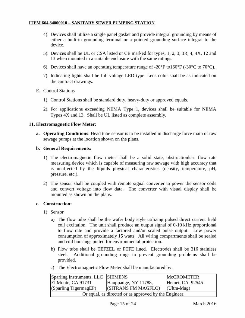
c) The Electromagnetic Flow Meter shall be manufactured by:
Sparling Instruments, LLC
El Monte, CA 91731
(Sparling TigermagEP)
SIEMENS
Hauppauge, NY 11788,
(SITRANS FM MAGFLO)
McCROMETER
Hemet, CA 92545
(Ultra-Mag)
Or equal, as directed or as approved by the Engineer.
ITEM 664.84000010 – SANITARY SEWER PUMPING STATION
Page 16 of 24 March 2016
2) Remote Electronics
a) Panel-mounted microprocessor based transmitter used to convert low level signals
from the flow tube to 4-20 mA output. Local operator interface keypad and
display to allow review and changing of transmitter settings. Capable of
displaying present flow rate in gallons per minute as well as totalized flow.
NEMA-4X transmitter enclosure and NEMA-7 rated junction box on meter for
sensor connections. Mount enclosure 48 inches above finish floor to
accommodate operator use.
b) Accuracy ± 0.5 percent of rate. Automatic zero. Continuous self-diagnostics
with fault messages in English. Battery backup of totalizer.
c) Manufacturer – Must be supplied by and compatible with the same manufacturer
as the flow meter sensor.
12. Miscellaneous:
a. Pipe Supports:
1) Black steel welded construction with stainless steel expansion bolts and hardware.
Coat all ferrous surfaces with two coats of coal tar epoxy.
b. Floor Drain and Drain Pipe:
1) Floor drain shall be single-body coated cast iron, equipped with bottom outlet, square
top, round hinged grate, or as approved.
2) Drain pipe shall be ductile iron pipe, or grey cast iron or cast standard weight, plain
end, unlined, conforming to the Cast Iron Soil Pipe Institute (CISPI) Standard 301.
Grey cast iron fittings shall be beaded end.
3) Acceptable Manufacturers
a) J.R. Smith Manufacturing Co.
b) Josam Manufacturing Co.
c) Or equal, as directed or as approved by the Engineer.
4) Refer to plans for location(s) of combination floor drain with integral backwater valve
and trap.
c. Backwater Valve:
1) PVC construction.
2) Noncorrosive flexible PVC flapper.
3) Removable plastic access cover secured with stainless steel bolts.
4) Refer to plans for location(s) of combination floor drain with integral backwater valve
and trap.
d. Wall Sleeves and Seals:
1) All penetrations shall be provided with a precast sleeve or cored opening. Sleeve size
shall be a minimum of 2 inches larger than the piping outside diameter.

ITEM 664.84000010 – SANITARY SEWER PUMPING STATION
Page 17 of 24 March 2016
2) Penetrations shall be sealed using a modular link style rubber seal. Manufactured by
Thunderline Corp., or equal, as directed or as approved by the Engineer.
e. Scrubber: For removal of odorous gases from municipal vent pipes with a 99.5+% gas
removal efficiency. Used for small vent applications and came standard with media
which is designed to remove a broad spectrum of odorous gases including mercaptans,
hydrocarbons, hydrogen sulfide and general sewer odors. Scrubber shall be delivered and
installed at the location noted on the plans or where directed by the Engineer. Including
but not limited scrubber, bolts, and mounting bracket.
f. Trash Basket: For removal unwanted materials that could damage the pumps. Trash
basket should have the following features:
1) All aluminum basket and rails
2) Solid aluminum wheels and stainless steel axles
3) Heavy duty ladder/guiderail combination
4) 1 3/8” type “D” rung with flat slip resistant surface
5) Bar screen style basket
6) Available without ladder rungs (guide rails only)
7) Stainless steel basket available
8) Stainless steel channel rail system available
g. Crane: Crane shall be Thern Captain Series 572 delivered and installed at the location
noted on the plans or where directed by the Engineer. Including but not limited crane,
bolts, power winch, wire rope, and base. Crane should have the following features:
1) Adjustable book angle
2) Bearings for smooth 360° rotation.
3) Handle on the mast makes rotation easy.
4) Power winch operation include 115 volt 1 phase ac electric winch with pendant
control and break
5) Epoxy finish. Corrosion resistant finish
6) Mast locks in four positions with hand tightened lock bolt
7) Up to 25’ long lift capability
8) 2,200 lb. capacity
9) Gusset style base for permanent installation and stability under load
10) Wire rope assemblies
h. Explosion Proof Blower: The materials selected for the explosion proof blower must be
listed as Class 1, Division 1 explosion proof. Product must be submitted and approved
prior to installation. Explosion proof blower must be capable of 525CFM (Minimum).
i. Explosion Proof Lighting: The materials selected must be Class 1 Division 1 explosion
proof rated, and UL listed. All materials must be submitted and approved prior to
installation.
j. Explosion Proof Switches: The materials selected must be Class 1 Division 1 explosion
proof rated, and UL listed.
13. General Requirements – Electrical: Secure necessary permits and pay all required fees
applicable to the work. Obtain NYBFU or NYS Electrical Inspection Certificate.
ITEM 664.84000010 – SANITARY SEWER PUMPING STATION
Page 18 of 24 March 2016
CONSTRUCTION DETAILS
1) General Product Delivery, Storage, and Handling: Fittings, valves, pipe, controls,
equipment, and other accessories shall be handled in such a manner as to ensure delivery to
the site in sound, undamaged condition. Take special care not to injure factory finishes.
Replace or make satisfactory repairs to pipe or fittings with damaged coatings or linings.
Store pipe, valves, and other accessories in conformance with the manufacturer's
recommendations.
2) Shop Drawings. A complete set of shop drawings covering all aspects of the pumping
station, valve chamber and appurtenances shall be submitted to the Engineer as a package.
Separate submittals of various components will not be accepted.
3) Manufacturer’s Representative. The Contractor shall arrange for a qualified service
representative(s) from the company(ies) manufacturing or supplying the pumping, controls,
dialer, flow meter, and related equipment to perform the duties herein described. Service
representative shall be responsible for all start-up and programming functions.
4) Electrical Installation: The Contractor shall make preliminary field tests to ensure that the
reconnection of the electrical pump control panel is correct. The manufacturer’s
representative shall supervise the installation of all submersible pump equipment. After
installation of the equipment has been completed and the equipment is presumably ready for
operation, but before it is operated by others, the manufacturer’s representative shall inspect,
operate, pretest and adjust the equipment. The Contractor shall assist in the pretest. The
Engineer shall be notified one (1) week in advance so he may attend and make notification to
the municipality’s operator or representative to be present for all testing. Engineer will
notify three (3) work days prior to pre-test. The inspection shall include, but not be limited
to, the following points as applicable:
a. Soundness (without cracked or otherwise damaged parts).
b. Completeness in all details as specified.
c. Correctness of setting, alignment and relative arrangement of various parts.
d. Adequacy and correctness of overall installation and performance.
The operation, testing and adjustment shall be as required to provide that the equipment is
left in proper condition for satisfactory operation under the conditions specified. On
completion of his work, the manufacturer’s or supplier’s representative shall submit in
triplicate to the Engineer a complete signed report of the results of his inspection, operation,
adjustment and tests. The report shall include detailed descriptions of the points inspected,
tests and adjustments made, quantitative results obtained if such are specified and a
certificate that the equipment conforms to the requirements of the Contract and is ready for
permanent operation and that nothing in the installation will render the manufacturer’s
warranty null and void.
Provide on-site startup and training for system operator. Eight (8) hours minimum required,
unless otherwise directed or approved by the Engineer after consultation with the system
operator.

ITEM 664.84000010 – SANITARY SEWER PUMPING STATION
Page 19 of 24 March 2016
5) Meter Installation:
a) The electromagnetic flow meter shall be installed in accordance with the manufacturer's
recommendations.
b) The flangeless wafer body sensor shall be installed between ANSI 150 flanges and
tightened with all-thread rods or long bolts. The center of the meter shall be mounted a
minimum of 3 straight pipe diameters on each end to any fitting or flow obstruction.
c) The remote transmitter panel shall be securely mounted in the control enclosure structure.
Provide adequate length of cable to sensor.
d) Provide on-site startup and training for system operator.
6) Pipe And Fitting, Installation: Inspect the pipe, fittings, and other materials for damage and
other defects. Reject all unsound or damaged material.
a) Cleanliness: Foreign material shall be prevented from entering the pipe and fittings while
they are being placed.
b) Cutting of Pipe:
1) Cut pipe in a neat workmanlike manner.
2) Ductile iron pipe may be cut with an abrasive pipe saw, rotary wheel cutter, guillotine
pipe saw, or milling wheel saw. Avoid damage to cement mortar lining.
3) Smooth all cut ends and edges by grinding.
c) Joints: Assemble joints in strict accordance with manufacturer's instructions using
recommended lubricants, gaskets, and sealing tape.
d) Painting
1) Paint all piping and accessories as specified or noted on plans.
2) Touch Up: Paint any previously uncoated bolts, fittings, tie rods, clamps, or other
accessories and touch up any scraped areas of the pipe.
7. Valves:
a. Set plumb unless otherwise noted on drawings.
b. Valves and other fittings shall have flanged joints unless otherwise specified.
c. Valve components shall be carefully inspected prior to installation. Valve discs shall be
opened and closed to make sure the valve operates properly, that stops and limiting
devices are properly set, and that the valve seats properly.
d. Strictly adhere to manufacturer's installation requirements.
8. Drain, Waste, and Vent Piping:
a. All drain and vent piping shall be installed as shown on the plans.
b. Install all necessary piping and appurtenances in order to provide a properly functioning
drain and vent system.
ITEM 664.84000010 – SANITARY SEWER PUMPING STATION
Page 20 of 24 March 2016
9. Painting
a. Paint all piping, valves, and applicable accessories.
b. Touch Up: Paint any previously uncoated bolts, fittings, tie rods, clamps, and
accessories.
c. Painting includes field painting of exposed bare and covered pipes, hangers, exposed
steel and iron work, and primed metal surfaces of mechanical and electrical equipment.
d. Do not paint prefinished items, concealed surfaces, finished metal surfaces, operating
parts, and labels.
e. Follow paint manufacturer’s instructions for storage and application of paint products.
f. Primer: Metal surfaces not factory primed shall receive a field application of a quick-
drying, rush-inhibitive, alkyd-based or epoxy-metal primer, as recommended by the paint
manufacturer. One coat required.
g. Finish Coat – Apply two coats of black semi-gloss acrylic-latex enamel (interior or
exterior, depending on location). Follow manufacturer’s recommendations for
application. Color shall be confirmed by system operator / owner.
10. Pump Station Installation:
a. Install the duplex pumps, piping, valves, control panel and alarm devices as shown on the
Contract Drawings and in strict accordance with the manufacturer's recommendations.
Operationally test the system for plumbing leaks, operation of valves and controls.
Check the pumping rate by timing the cycle time between on-off levels.
b. Electrical work shall conform to all applicable State and Local Codes and the National
Electrical Code (N.E.C.).
c. Items of specific manufacturers shall be installed in strict accordance with manufacturer's
printed instructions and/or manufacturer's representative's directions.
d. Provide grounding system as per the N.E.C.
e. All power and control cables from control panel to the pump station shall be continuous.
No splices or junction boxes shall be used in wet well. The wet well shall be considered
a Class I, Division 1, Group D, location.
f. All access hatches shall be installed per manufacturer's instructions.
g. Provide intermediate platform with removable corrosion-resistant grating where required.
Flygt “TOP” Fiberglass basin insert, or equivalent, shall be sized for each pump
installation.
h. Immediately after the placing of one section on another, the exterior portion of the joint
shall be filled with Axpandcrete RM, or equivalent. After completing the joint, the entire
exterior surface of the station shall be coated with two heavy, troweled bitumastic
coatings. The interior of the joint shall be filled with “Anti-Hydro” mortar and give a
smooth finish.
ITEM 664.84000010 – SANITARY SEWER PUMPING STATION
Page 21 of 24 March 2016
11. Explosion Proof Equipment: Install explosion proof blower in accordance with the
manufacturer’s directions. See Contract Plans for location, unless directed otherwise by the
engineer. Blower motor shall be installed in accordance with the manufacturer's installation
instructions and written requirements of the manufacturer of the driven equipment.
Explosion proof lighting shall be installed as per the manufacturer’s instruction. Explosion
proof lighting shall be installed where shown on the approved project plans or where directed
by the engineer.
Explosion proof switches shall be installed as per the manufacturer’s instruction. Explosion
proof switches shall be installed where shown on the approved project plans or where
directed by the engineer.
12. Field Test. After installation of the unit together with all accessories, it shall be put in first
class operating condition; and after inspection, testing, operation and adjustments have been
completed by the manufacturer’s representative and after the manufacturer’s representative
has submitted his report to the Engineer, the pumping equipment shall be field tested by the
Contractor in the presence of the Engineer to demonstrate the ability of the unit to operate
properly without vibration or overheating.
All defects or defective equipment shall be corrected or replaced at the expense of the
Contractor and, if necessary, the tests shall be repeated until satisfactory results are obtained.
The Contractor shall furnish all labor, piping, equipment, water, power and materials
necessary for testing.
13. Operating Instructions and Training. The Contractor shall furnish five (5) bound copies
of instruction manuals covering operation and maintenance of all equipment furnished. The
manuals shall be complete with wiring diagrams, lubrication schedules, drawings, functional
descriptions, cuts, troubleshooting recommendations, parts lists and other information
required for the proper operation, maintenance, repair and adjustment of the equipment. All
parts shall be numbered or otherwise clearly identified to facilitate ordering of replacements.
Upon completion of all work and all tests, the Contractor shall furnish the necessary skilled
labor and helpers for operating the system and equipment for a period of one (1) day. During
this period, he shall instruct the Owner or his representative fully in the operations,
adjustment and maintenance of all equipment furnished.
14. General
a. Provide conduit seals in all conduits between control panel and wet well.
b. Provide separate conduit for 4-20ma wiring to the pressure transducer. Do not run with
any other wiring (including the control wiring for the redundant level control system).
c. Provide one spare control conduit from the wet well equal in size to those used.
Terminate this spare conduit below the control panel with sufficient space to add a seal
and connection to the control panel in the future.
d. The Contractor shall furnish and install new submersible pump electric supply cables
with sufficient length to reach the electric control panel. Under no circumstance will
splices in this cable be permitted. Each electric supply cable will be housed individually
ITEM 664.84000010 – SANITARY SEWER PUMPING STATION
Page 22 of 24 March 2016
in their own conduit running from the sanitary pump station wet well to the electric
control panel. The electric cable installation shall be done by the qualified service
representative and shall be included in their duties as described under the Construction
Details, Section 3) and 4).
15. Warranty. Contractor shall provide a warranty for the work covered by this special
specification, transferrable to the municipality/system operator, upon completion of the work.
This warranty shall insure that defects not due to improper use that develop within two (2)
years from the date the completed project is turned over to the municipality/system operator
are corrected. Warranty includes full parts, labor, materials, and other necessary expenses.
16. Controls Installation. Install all pump control system components as per the manufacturer’s
installation instructions, and in compliance with the most current version of the National
Electric Code. Provide a complete and working installation at each location shown for all
required equipment.
The Installer shall be experienced in the installation of digital displays, measuring
instruments, and programmable logic control panels (PLC). Installation should be performed
by a mechanical/electrical contractor or qualified persons as specified by the contractor / end-
user prior to the system being commissioned. The manufacturer/supplier should provide
sufficient documentation that allows/support the electrical and mechanical installation of
each digital display by independent contractors as specified and shown on the plan.
The Contractor shall have all necessary basic materials to perform the work at the site. In
addition, the Contractor shall perform any corrective measures necessary, due to the
installation of this equipment. Prior to commissioning/Startup the supplier/manufacturer of
the system shall be available to ensure installation has been performed correctly to ensure
trouble free commissioning/startup. The supplier/manufacturer of the system shall be
available to provide commissioning/startup service for the instrumentation system locally to
ensure all components operate within specified ranges for accuracy and repeatability, and all
readings are displayed across the system components consistently. The Contractor shall
calibrate all components to meet the requirements of the specified equipment. The work site
shall be cleaned of any debris or remnants of the work of this Contract.
Demonstration and Training: The supplier/manufacturer of the digital display system shall be
available as necessary to provide local operator demonstration and training to include,
operation and troubleshooting using the operator interface, and operator commands that are
non-service related.
Install the signal conditioners as per the manufacturer’s instructions. Installation of signal
conditioners shall conform to the most recent version of the national electric code, and must
comply with the below list of requirements:
a. All control power, and data communications wire shall be factory wired and harnessed
within the equipment enclosure
b. Where external circuit connections are required, terminal blocks shall be provided and
the manufacturer's drawings must clearly identify the interconnection requirements
including wire type to be used.
c. Install all control equipment, accessories, wiring, and piping in a neat and workmanlike
manner. All control devices must be installed in accessible locations. This contractor

ITEM 664.84000010 – SANITARY SEWER PUMPING STATION
Page 23 of 24 March 2016
shall verify that all control devices furnished under this Section are functional and
operating the instrument or equipment.
Installers:
1). The Installer shall be experienced in the installation of low voltage, control panel
components and analog signal requirements.
2). Installation should be performed by a mechanical/electrical contractor or qualified
persons as specified by the contractor/end-user prior to the system being
commissioned.
3). The manufacturer/supplier should provide sufficient documentation that allows /
supports the electrical and mechanical installation of the signal conditioner by
independent contractors as specified and shown on the plan.
Preparation:
1). The Contractor shall have all necessary basic materials to perform the work at the
site. In addition, the Contractor shall perform any corrective measures necessary,
due to the installation of this instrument.
Field Quality Control:
1). Prior to commissioning/Startup the supplier/manufacturer of the system shall be
available to ensure installation has been performed correctly, and to ensure
trouble free commissioning/startup.
2). Provide all technical coordination, installation, integration, and testing of all
components.
Identification:
1). Install a permanent wire marker on each wire at each termination.
2). Identifying numbers and letters on the wire markers shall correspond to those on
the wiring diagrams used for installing the systems.
3). Wire markers shall retain their markings after cleaning.
System Startup:
1). The supplier/manufacturer of the system shall be available to provide
commissioning/startup service for the instrumentation system locally to ensure the
following:
2). All components operate within specified ranges for accuracy and repeatability.
3). All readings are displayed across the system components consistently.
Cleaning:
1). The work site shall be cleaned of any debris or remnants of the work of this
Contract.
ITEM 664.84000010 – SANITARY SEWER PUMPING STATION
Page 24 of 24 March 2016
Protection:
1) Provide protection, if needed by, fabricating a support or guard for the instrument
to prevent damage during access to the installation location.
2) Install devices and equipment in accordance with manufacturer's instructions.
Install individual relays and time delay relays in enclosures. Make electrical
wiring interconnections as shown on Drawings. Label each terminal and
conductor at every termination point. Identification and labels shall be unique to
the installation of the new components.
METHOD OF MEASUREMENT
There will be no measurement under this item, the work described herein to be paid for on a
lump sum basis.
BASIS OF PAYMENT
Payment for Sanitary Sewer Pumping Station will be made on a lump sum basis.
The Lump Sum price bid for this item shall include the cost of all equipment, materials and labor
required for a complete installation of a Sanitary Sewer Pumping Station, (including all fees for
inspection, service connections, licenses, electrical energy, excavation, backfill, sheeting and any
other cost that may incur in constructing/installation of the Sanitary Sewer Pumping Station)
ready for its intended use.