Embed Size (px)
Citation preview
TYDEX-Format Reference Manual, Release 1.3
TYDEX
TYDEX-Format
Description and
Reference Manual
Release 1.3
Initiated by the TYDEX Workshop
worked out by
Dipl.-Ing. H.-J. Unrau, Universität Karlsruhe (TH)
Dr.-Ing. J. Zamow, Dr.Ing.h.c.F.Porsche AG
09.01.1997
TYDEX-Format Reference Manual, Release 1.3 Page 2
TYDEX Contents
Contents Page
1. Introduction 4
1.1 Participating Companies 5
2. Description of the File Structure 6
2.1 General Remarks 6
2.2 Keywords 7
2.2.1 **HEADER 8
2.2.2 **COMMENTS 9
2.2.3 **CONSTANTS 9
2.2.4 **MEASURCHANNELS 11
2.2.5 **MEASURDATA 13
2.2.6 **MODELDEFINITION 14
2.2.7 **MODELPARAMETERS 17
2.2.8 **MODELCOEFFICIENTS 18
2.2.9 **MODELCHANNELS 19
2.2.10 **MODELOUTPUTS 20
2.2.11 **MODELEND 21
2.2.12 **END 21
2.3 Physical Units 22
2.4 Examples 25
2.5 Parameter List 34
2.5.1 HEADER 34
2.5.2 CONSTANTS and CHANNELS 35
2.6 Axis Systems 47
2.6.1 C-Axis System 47
2.6.2 H-Axis System 49
2.6.3 W-Axis System 51
TYDEX-Format Reference Manual, Release 1.3 Page 3
TYDEX Contents
2.7 Longitudinal Slip 53
2.7.1 Definition 53
2.7.2 Approximation 54
3. Literature 55
TYDEX-Format Reference Manual, Release 1.3 Page 4
TYDEX 1. Introduction
1. Introduction
The Tyre Data Exchange Format (TYDEX) has been developed and unified by an
international tyre working group to make the tyre measurement data exchange
easier.
This format can be used by anybody without special permission and without paying
any licence fee.
Proposals for further extensions to this format should be given to the chairman of the
TYDEX Working Group, to persons listed below or to other members of this group.
JJaann JJ..MM.. vvaann OOoosstteenn ((CChhaaiirrmmaann ooff tthhee TTYYDDEEXX WWoorrkkiinngg GGrroouupp TTMM--TTMM)) TTNNOO RRooaadd--VVeehhiicclleess RReesseeaarrcchh IInnssttiittuuttee PP..OO.. BBooxx 66003333 NNLL--22660000 JJAA DDeellfftt PPhhoonnee:: ++3311 1155 226699 66442200 FFaaxx:: ++3311 1155 226699 77331144 DDiippll..--IInngg.. HHaannss--JJooaacchhiimm UUnnrraauu UUnniivveerrssiittäätt KKaarrllssrruuhhee ((TTHH)) IInnssttiittuutt ffüürr MMaasscchhiinneennkkoonnssttrruukkttiioonnsslleehhrree uunndd KKrraaffttffaahhrrzzeeuuggbbaauu KKaaiisseerrssttrr..1122 DD--7766112288 KKaarrllssrruuhhee PPhhoonnee:: ++4499--772211//660088--33779955 FFaaxx:: ++4499--772211//660088--66005511
TYDEX-Format Reference Manual, Release 1.3 Page 5
TYDEX 1.1 Participating Companies
1.1 Participating Companies
Following companies or institutes are supporting the TYDEX file format described
here:
BMW AG Germany
Robert Bosch GmbH Germany
Centro Ricerche FIAT Italy
Continental AG Germany
Daimler-Benz AG Germany
FTH Esslingen Germany
Ford Werke AG Germany
Goodyear S.A. Luxembourg
IPG GmbH Germany
Mercedes-Benz AG Germany
Michelin France
NedCar The Netherlands
Porsche AG Germany
PSA France
Steyr-Daimler-Puch Austria
Toyota (TCL) Japan
Volkswagen AG Germany
Volvo Car Corp. Sweden
Volvo Truck Corp. Sweden
TNO The Netherlands
University of Berlin Germany
University of Delft The Netherlands
University of Karlsruhe Germany
University of Vienna Austria
TYDEX-Format Reference Manual, Release 1.3 Page 6
TYDEX 2.1 General Remarks
2. Description of the File Structure
An example of the file structure can be seen in chapter 2.4.
The proposed file extension of the TYDEX data file is .tdx (e.g. a complete file name
may be MEAS01.TDX) .
2.1 General Remarks
The keywords, the physical units and all other text may be written either in upper or in
lower case letters or mixed (TIME=Time=time). The 8-bit ANSI-ASCII character set
has to be used. National character sets are not allowed.
Each record line may be 80 characters long except the **MEASURDATA, the
**MODELCOEFFICIENTS and the **MODELOUTPUTS sections for which it will be
more comfortable to have one line per sample. In that case the record length may be
up to 255 characters.
Blank lines are ignored. They can be used to structure the file and to improve its
readability.
Comments can be given in lines starting with ! (exclamation mark). These lines may
have any position in any block of the file, but they will be ignored during reading the
file. These comment lines may be helpful to add remarks using an editor.
Example:
Column
1 11 41 51 61 71
! The rest of this line is comment that will be ignored during reading
TYDEX-Format Reference Manual, Release 1.3 Page 7
TYDEX 2.2 Keywords
2.2 Keywords
Every keyword (except **MODELEND and **END) is the header of a section
containing special information on the data.
The data file may consist of up to 12 keywords:
****HHEEAADDEERR
****CCOOMMMMEENNTTSS
****CCOONNSSTTAANNTTSS
****MMEEAASSUURRCCHHAANNNNEELLSS
****MMEEAASSUURRDDAATTAA
****MMOODDEELLDDEEFFIINNIITTIIOONN
****MMOODDEELLPPAARRAAMMEETTEERRSS
****MMOODDEELLCCOOEEFFFFIICCIIEENNTTSS
****MMOODDEELLCCHHAANNNNEELLSS
****MMOODDEELLOOUUTTPPUUTTSS
****MMOODDEELLEENNDD
****EENNDD
All keywords start in column 1 with 2 asterisks. They may be written in lower,
upper case or mixed case letters (HEADER=Header=header). They must not
contain any blanks.
The keywords **HEADER and **END must appear in every file. The other
keywords are optional.
If sections concerning the tyre model are used, the keywords
**MODELDEFINITION and **MODELEND must appear.
Only one **CONSTANTS section is allowed in one data file. This
**CONSTANTS section is valid for all sections referring to the measurement
and the model.
TYDEX-Format Reference Manual, Release 1.3 Page 8
TYDEX 2.2 Keywords
If **MEASURCHANNELS is given also a **MEASURDATA section must occur.
Only one **MEASURCHANNELS and one **MEASURDATA keyword is
allowed.
If sections concerning the tyre model are used they have to be pooled in one
block. In the beginning of this block the section **MODELDEFINITION
appears, in which the used tyre model is defined and a model reference code
is shown to avoid mistakes. In the end of the block **MODELEND appears so
that it is clear that all sections between **MODELDEFINITION and
**MODELEND are related to one tyre model.
Several blocks of MODEL sections are allowed. This makes it possible to
describe lateral force and aligning moment models in consecutive sections
within the same file.
If more than one block of MODEL sections is used in one file, the connected
**MODELDEFINITION and **MODELEND also appears several times. The
blocks have to refer to the same testing conditions, i.e. to the same
**CONSTANTS section.
For certain tyre models, the mixing of model and measurement data does not
appear to be sensible. If model data concerning these tyre models is to be
stored in TYDEX format, the keywords **MEASURCHANNELS and
**MEASURDATA do not appear.
2.2.1 **HEADER
This section contains information to identify the measurement. It is suitable for the file
management.
This keyword must occur in every TYDEX data file !
It must be the first keyword.
It may be written in lower or upper case letters or mixed.
TYDEX-Format Reference Manual, Release 1.3 Page 9
TYDEX 2.2 Keywords
This section consists of only 5 parameters, as shown in the following example:
Column
1 11 41 51 61 71
**HEADER
RELEASE Release of TYDEX-Format 1.3
MEASID Measurement ID 05039ABC
SUPPLIER Data Supplier MICHELIN
DATE Date 26/01/97
CLCKTIME Clocktime 09:50
For further details, see chapter 2.5.1 .
2.2.2 **COMMENTS
This section contains information which cannot be put into other blocks or which is
additional user information. This block will be read in during the postprocessing
phase and can be printed or plotted (instead of comment lines starting with „!“).
Lines after this keyword have free format. They can be generated by a
computer program as well as using an editor.
An unlimited number of comment lines is allowed. This section ends one line
before the next keyword starting with 2 asterisks (**).
In this section the quality of the model-to-measurements-fitting can be
specified.
2.2.3 **CONSTANTS
This section contains measurement and model data and character information which
is constant for the whole measurement or model given in this file. Normally, all
information about tyre, rim and test conditions is given in this section if a parameter
has been defined (see chapter 2.5). If any information is unknown it can be omitted
although there is a parameter. However, the user should be endeavoured to give all
information available for the parameters which have been defined.
TYDEX-Format Reference Manual, Release 1.3 Page 10
TYDEX 2.2 Keywords
Numerical values given in the **CONSTANTS section instead of the
**MEASURDATA or **MODELOUTPUT sections save disk space, but they can be
used as if they were measured or modelled (e.g. by expansion to a full vector during
postprocessing).
The number of constants is not limited.
The names of the constants are fixed and have definite meanings to use them
for an automated postprocessing system (see chapter 2.5.2).
The given physical unit makes it possible to switch automatically to another unit.
The **CONSTANTS section has the following format:
Column
1 11 41 51 61 71
pppppppp text unit value
using
pppppppp parameter (see parameter list below)
can be written in upper case, lower case or mixed case letters
max. 8 characters long
starting in column 1
text channel text, either in English or in another language
spelling not fixed, max. 29 characters long
starting in column 11
unit physical unit (see list of allowed physical units below)
starting in column 41
value may be either a numerical value or a text string (depending on
parameter)
starting in column 51
TYDEX-Format Reference Manual, Release 1.3 Page 11
TYDEX 2.2 Keywords
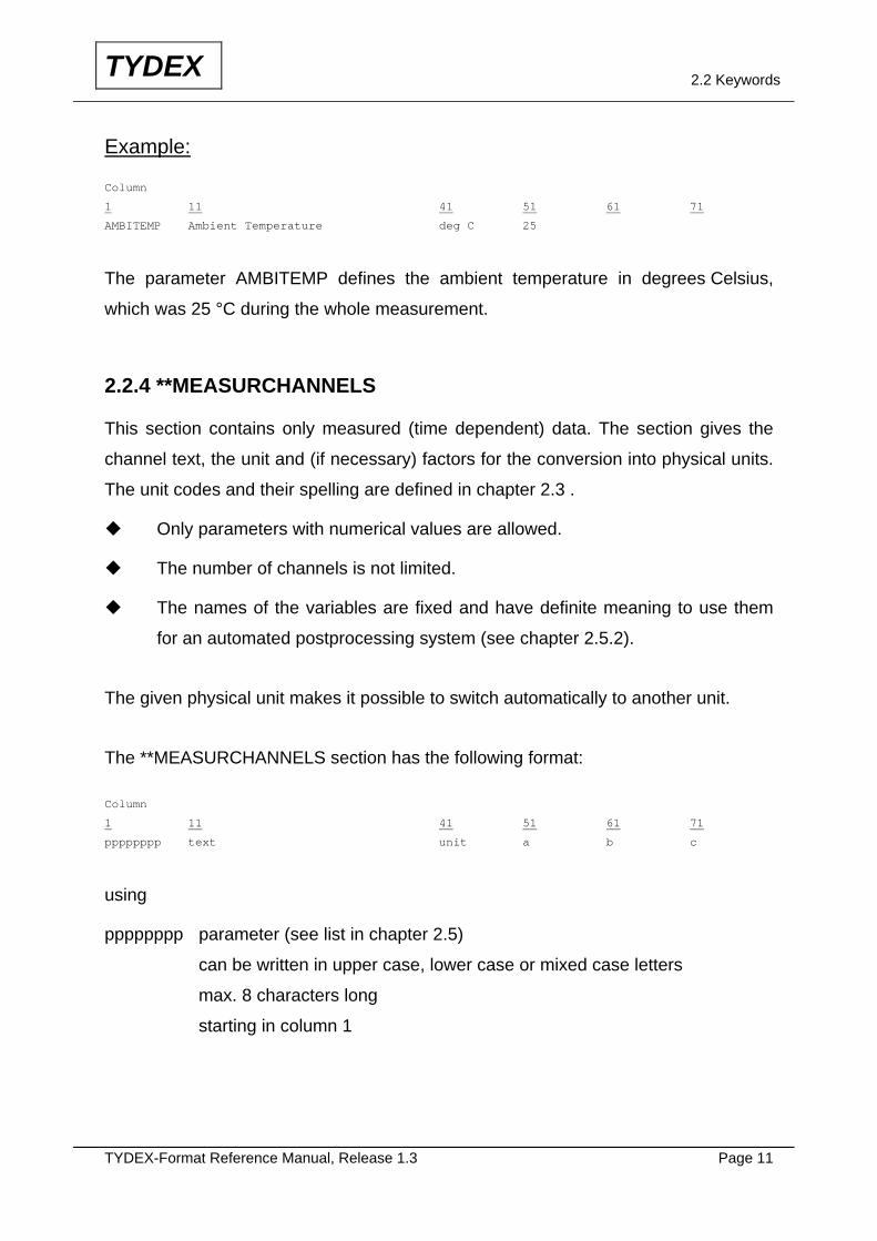
Example:
Column
1 11 41 51 61 71
AMBITEMP Ambient Temperature deg C 25
The parameter AMBITEMP defines the ambient temperature in degrees Celsius,
which was 25 °C during the whole measurement.
2.2.4 **MEASURCHANNELS
This section contains only measured (time dependent) data. The section gives the
channel text, the unit and (if necessary) factors for the conversion into physical units.
The unit codes and their spelling are defined in chapter 2.3 .
Only parameters with numerical values are allowed.
The number of channels is not limited.
The names of the variables are fixed and have definite meaning to use them
for an automated postprocessing system (see chapter 2.5.2).
The given physical unit makes it possible to switch automatically to another unit.
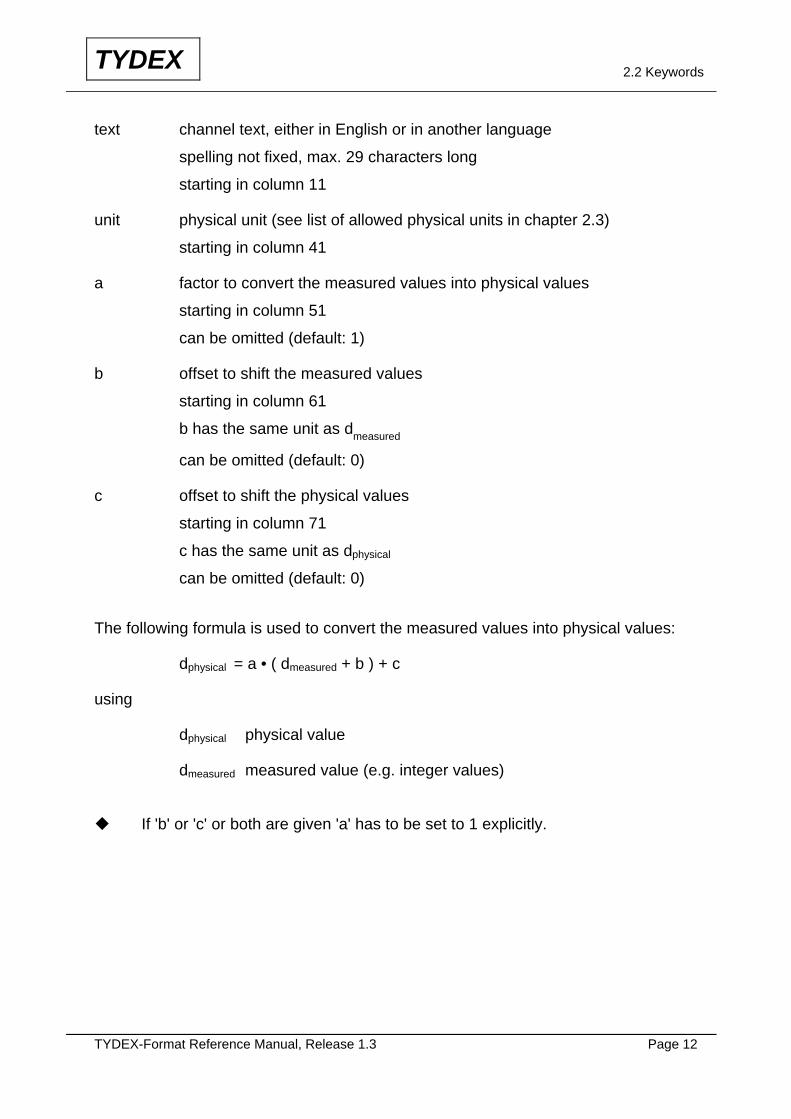
The **MEASURCHANNELS section has the following format:
Column
1 11 41 51 61 71
pppppppp text unit a b c
using
pppppppp parameter (see list in chapter 2.5)
can be written in upper case, lower case or mixed case letters
max. 8 characters long
starting in column 1
TYDEX-Format Reference Manual, Release 1.3 Page 12
TYDEX 2.2 Keywords
text channel text, either in English or in another language
spelling not fixed, max. 29 characters long
starting in column 11
unit physical unit (see list of allowed physical units in chapter 2.3)
starting in column 41
a factor to convert the measured values into physical values
starting in column 51
can be omitted (default: 1)
b offset to shift the measured values
starting in column 61
b has the same unit as dmeasured
can be omitted (default: 0)
c offset to shift the physical values
starting in column 71
c has the same unit as dphysical
can be omitted (default: 0) The following formula is used to convert the measured values into physical values:
dphysical = a • ( dmeasured + b ) + c
using
dphysical physical value
dmeasured measured value (e.g. integer values)
If 'b' or 'c' or both are given 'a' has to be set to 1 explicitly.
TYDEX-Format Reference Manual, Release 1.3 Page 13
TYDEX 2.2 Keywords
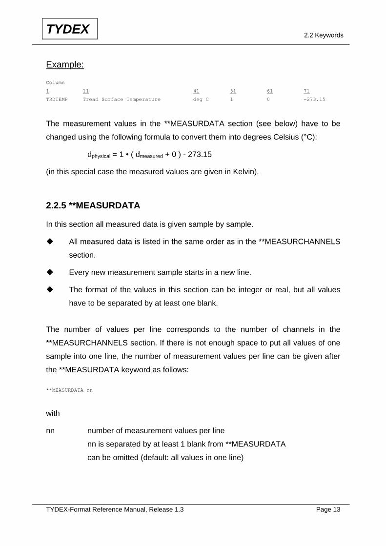
Example:
Column
1 11 41 51 61 71
TRDTEMP Tread Surface Temperature deg C 1 0 -273.15
The measurement values in the **MEASURDATA section (see below) have to be
changed using the following formula to convert them into degrees Celsius (°C):
dphysical = 1 • ( dmeasured + 0 ) - 273.15
(in this special case the measured values are given in Kelvin).
2.2.5 **MEASURDATA
In this section all measured data is given sample by sample.
All measured data is listed in the same order as in the **MEASURCHANNELS
section.
Every new measurement sample starts in a new line.
The format of the values in this section can be integer or real, but all values
have to be separated by at least one blank.
The number of values per line corresponds to the number of channels in the
**MEASURCHANNELS section. If there is not enough space to put all values of one
sample into one line, the number of measurement values per line can be given after
the **MEASURDATA keyword as follows:
**MEASURDATA nn
with
nn number of measurement values per line
nn is separated by at least 1 blank from **MEASURDATA
can be omitted (default: all values in one line)

TYDEX-Format Reference Manual, Release 1.3 Page 14
TYDEX 2.2 Keywords
This feature makes it possible to store an unlimited number of channels in the data
file.
Example:
The measurement consists of 20 measurement channels (20 values per sample), but
only 8 values can be put into one line. The **MEASURDATA section starts as follows
(only 2 samples are shown):
**MEASURDATA 8
1231.7 8467.3 0.02604 329.6 -142E3 0.01828 17.947 182.9
48.9274 27.2 2483 -3.192 -93716 -1024 +4.7E-3 9376.
111.11 222.22 3333.3 4444.4
1231.7 8467.3 0.02604 329.6 -143E3 0.01828 17.947 182.9
48.9274 27.2 2483 -3.512 -93716 -1024 +4.7E-3 9179.
111.11 222.22 3333.3 4444.4
This format is not very clearly arranged, but there is no problem to read the data set
with a computer program automatically.
2.2.6 **MODELDEFINITION
This section is the first one for a model description. The first line is formatted and
contains the keyword MODELREF followed by the name of the model in column 11,
the supplier’s model reference code in column 41 and the supplier name in column
51.
Example:
Column
1 11 41 51 61 71
**MODELDEFINITION
MODELREF IPG-TIRE 3.6 IPG
TYDEX-Format Reference Manual, Release 1.3 Page 15
TYDEX 2.2 Keywords
The following lines in this section are used to define which are the inputs and the
outputs of the model. For input data, the minimum and maximum values allowed for
each parameter can be specified in order to lay down a validity domain.
The unit codes and their spelling are defined in chapter 2.3.
The number of lines is not limited.
The model supplier is allowed to use variables not mentioned in the parameter
list (see chapter 2.5), but in this case he is obliged to give a definition to his
customer.
The given physical unit makes it possible to switch automatically to another unit.
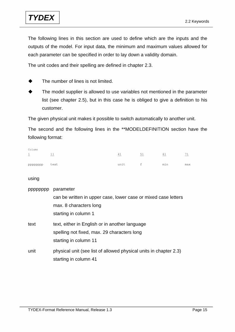
The second and the following lines in the **MODELDEFINITION section have the
following format:
Column
1 11 41 51 61 711
11
pppppppp text unit f min max
using
pppppppp parameter
can be written in upper case, lower case or mixed case letters
max. 8 characters long
starting in column 1
text text, either in English or in another language
spelling not fixed, max. 29 characters long
starting in column 11
unit physical unit (see list of allowed physical units in chapter 2.3)
starting in column 41

TYDEX-Format Reference Manual, Release 1.3 Page 16
TYDEX 2.2 Keywords
f indicator for input / output of the model
'out' denoting output data of the model
'in' denoting input data of the model
starting in column 51
min minimum value allowed for the input channel
starting in column 61
can be omitted (default: no limit)
no value for output channels
max maximum value allowed for the input channel
starting in column 71
can be omitted (default: no limit)
no value for output channels If some specific information about the model has to be given to the user of the model
(e.g. the quality of the model-to-measurements-fitting) it may be transmitted as
comment lines.
Example:
Column
1 11 41 51 61 71
**MODELDEFINITION
MODELREF Pacejka Magic Formula (FYH) ADY9006A MICHELIN
FYH Lateral Force N out
FZH Vertical Force kN in 0.5 10
SLIPANGL Slip Angle deg in -9 9
INCLANGL Inclination Angle deg in -5 5
!
! ----- Quality identification of the model -----
! ETR Residual Standard Deviation N 55.10
! TAUXERR Error Ratio % 2.47
! ECARTMAX Maximum deviation N 118.45
TYDEX-Format Reference Manual, Release 1.3 Page 17
TYDEX 2.2 Keywords
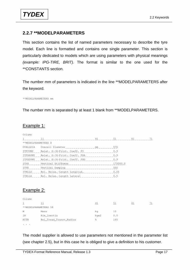
2.2.7 **MODELPARAMETERS
This section contains the list of named parameters necessary to describe the tyre
model. Each line is formatted and contains one single parameter. This section is
particularly dedicated to models which are using parameters with physical meanings
(example: IPG-TIRE, BRIT). The format is similar to the one used for the
**CONSTANTS section.
The number mm of parameters is indicated in the line **MODELPARAMETERS after
the keyword.
**MODELPARAMETERS mm
The number mm is separated by at least 1 blank from **MODELPARAMETERS.
Example 1:
Column
1 11 41 51 61 71
**MODELPARAMETERS 8
OVALLDIA Overall Diameter mm 576
ITFYVMY Relat. G-/H-Frict. Coeff. FY 0.9
ITFXAVMY Relat. G-/H-Frict. Coeff. FXA 0.9
ITFXDVMY Relat. G-/H-Frict. Coeff. FXD 0.9
ITVS Vertical Stiffness 175000.0
ITVD Vertical Damping 500
ITRLLO Rel. Relax.-Length Longitud. 0.05
ITRLLA Rel. Relax.-Length Lateral 0.5
Example 2:
Column
1 11 41 51 61 71
**MODELPARAMETERS 58
M Mass kg 10
IR Rim_Inertia kgm2 0.5
RTTR Rel_Tread_Transv_Radius % 165
. . .
The model supplier is allowed to use parameters not mentioned in the parameter list
(see chapter 2.5), but in this case he is obliged to give a definition to his customer.
TYDEX-Format Reference Manual, Release 1.3 Page 18
TYDEX 2.2 Keywords
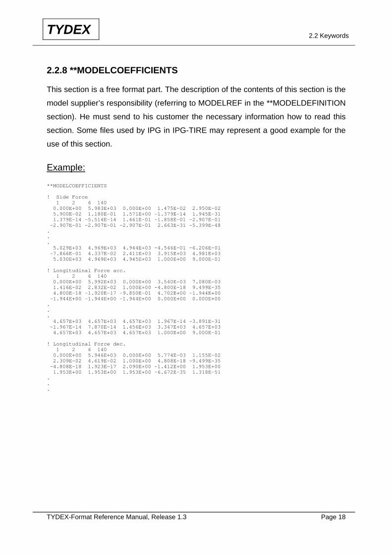
2.2.8 **MODELCOEFFICIENTS
This section is a free format part. The description of the contents of this section is the
model supplier’s responsibility (referring to MODELREF in the **MODELDEFINITION
section). He must send to his customer the necessary information how to read this
section. Some files used by IPG in IPG-TIRE may represent a good example for the
use of this section.
Example:
**MODELCOEFFICIENTS ! Side Force 1 2 6 140 0.000E+00 5.983E+03 0.000E+00 1.475E-02 2.950E-02 5.900E-02 1.180E-01 1.571E+00 -1.379E-14 1.945E-31 1.379E-14 -5.514E-14 1.461E-01 -1.858E-01 -2.907E-01 -2.907E-01 -2.907E-01 -2.907E-01 2.663E-31 -5.399E-48 . . . 5.029E+03 4.969E+03 4.944E+03 -4.546E-01 -6.206E-01 -7.866E-01 4.337E-02 2.411E+03 3.915E+03 4.981E+03 5.030E+03 4.969E+03 4.945E+03 1.000E+00 9.000E-01 ! Longitudinal Force acc. 1 2 6 140 0.000E+00 5.992E+03 0.000E+00 3.540E-03 7.080E-03 1.416E-02 2.832E-02 1.000E+00 -4.800E-18 9.499E-35 4.800E-18 -1.920E-17 -9.850E-01 4.702E+00 -1.944E+00 -1.944E+00 -1.944E+00 -1.944E+00 0.000E+00 0.000E+00 . . . 4.657E+03 4.657E+03 4.657E+03 1.967E-14 -3.891E-31 -1.967E-14 7.870E-14 1.456E+03 3.347E+03 4.657E+03 4.657E+03 4.657E+03 4.657E+03 1.000E+00 9.000E-01 ! Longitudinal Force dec. 1 2 6 140 0.000E+00 5.946E+03 0.000E+00 5.774E-03 1.155E-02 2.309E-02 4.619E-02 1.000E+00 4.808E-18 -9.499E-35 -4.808E-18 1.923E-17 2.090E+00 -1.412E+00 1.953E+00 1.953E+00 1.953E+00 1.953E+00 -6.672E-35 1.318E-51 . . .
TYDEX-Format Reference Manual, Release 1.3 Page 19
TYDEX 2.2 Keywords
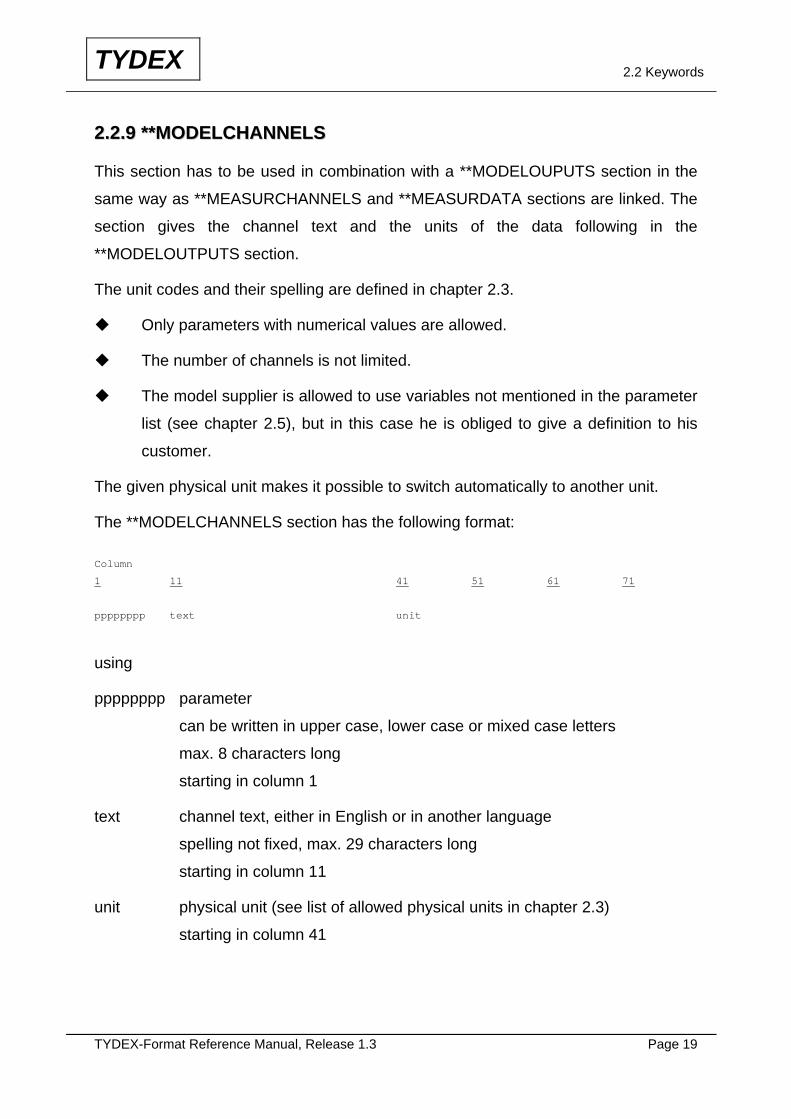
22..22..99 ****MMOODDEELLCCHHAANNNNEELLSS
This section has to be used in combination with a **MODELOUPUTS section in the
same way as **MEASURCHANNELS and **MEASURDATA sections are linked. The
section gives the channel text and the units of the data following in the
**MODELOUTPUTS section.
The unit codes and their spelling are defined in chapter 2.3.
Only parameters with numerical values are allowed.
The number of channels is not limited.
The model supplier is allowed to use variables not mentioned in the parameter
list (see chapter 2.5), but in this case he is obliged to give a definition to his
customer.
The given physical unit makes it possible to switch automatically to another unit.
The **MODELCHANNELS section has the following format:
Column
1 11 41 51 61 711
11
pppppppp text unit
using
pppppppp parameter
can be written in upper case, lower case or mixed case letters
max. 8 characters long
starting in column 1
text channel text, either in English or in another language
spelling not fixed, max. 29 characters long
starting in column 11
unit physical unit (see list of allowed physical units in chapter 2.3)
starting in column 41
TYDEX-Format Reference Manual, Release 1.3 Page 20
TYDEX 2.2 Keywords
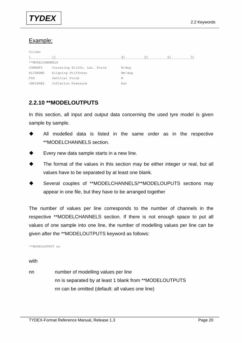
Example:
Column
1 11 41 51 61 71
**MODELCHANNELS
CORNSFY Cornering Stiffn. Lat. Force N/deg
ALIGNSMZ Aligning Stiffness Nm/deg
FZH Vertical Force N
INFLPRES Inflation Pressure bar
2.2.10 **MODELOUTPUTS
In this section, all input and output data concerning the used tyre model is given
sample by sample.
All modelled data is listed in the same order as in the respective
**MODELCHANNELS section.
Every new data sample starts in a new line.
The format of the values in this section may be either integer or real, but all
values have to be separated by at least one blank.
Several couples of **MODELCHANNELS/**MODELOUPUTS sections may
appear in one file, but they have to be arranged together
The number of values per line corresponds to the number of channels in the
respective **MODELCHANNELS section. If there is not enough space to put all
values of one sample into one line, the number of modelling values per line can be
given after the **MODELOUTPUTS keyword as follows:
**MODELOUTPUT nn
with
nn number of modelling values per line
nn is separated by at least 1 blank from **MODELOUTPUTS
nn can be omitted (default: all values one line)
TYDEX-Format Reference Manual, Release 1.3 Page 21
TYDEX 2.2 Keywords
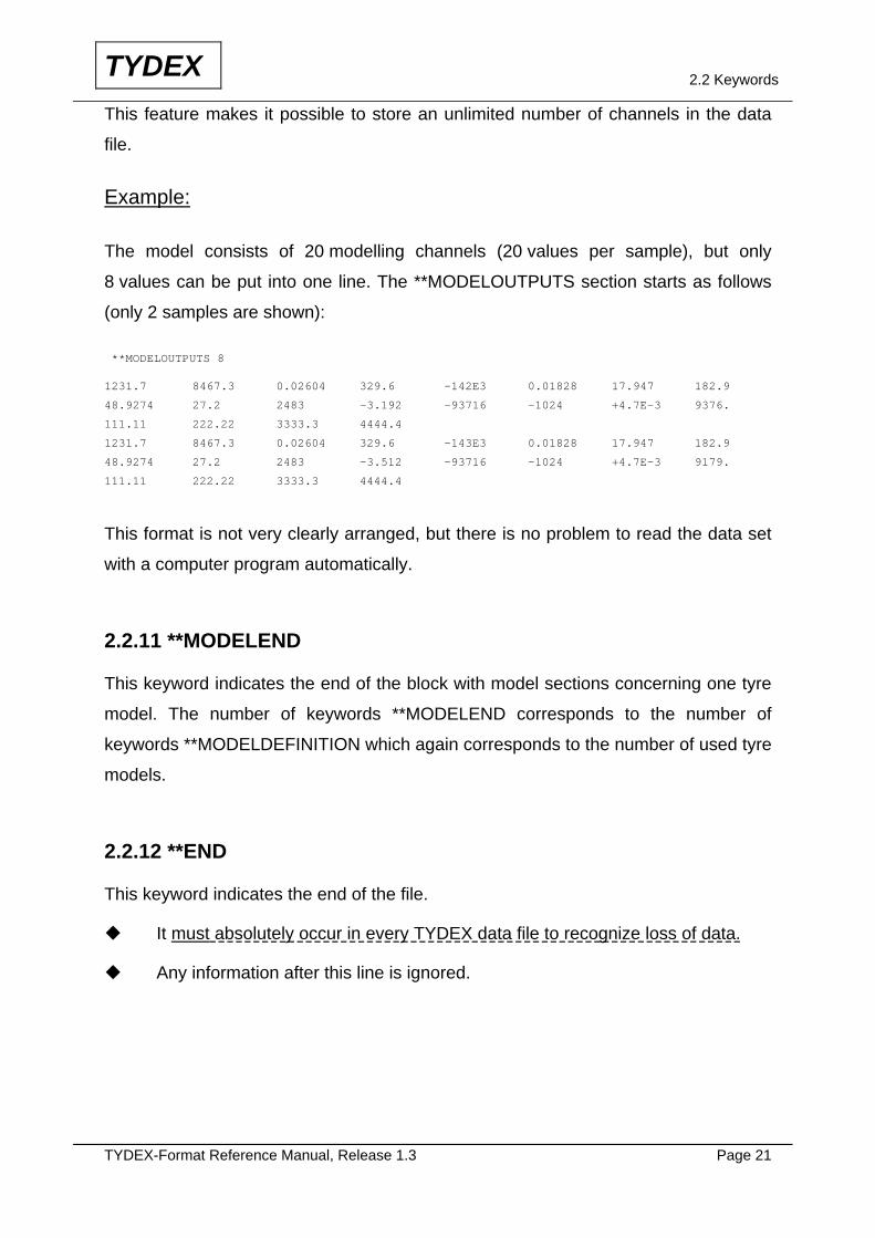
This feature makes it possible to store an unlimited number of channels in the data
file.
Example:
The model consists of 20 modelling channels (20 values per sample), but only
8 values can be put into one line. The **MODELOUTPUTS section starts as follows
(only 2 samples are shown):
**MODELOUTPUTS 8
1231.7 8467.3 0.02604 329.6 -142E3 0.01828 17.947 182.9
48.9274 27.2 2483 -3.192 -93716 -1024 +4.7E-3 9376.
111.11 222.22 3333.3 4444.4
1231.7 8467.3 0.02604 329.6 -143E3 0.01828 17.947 182.9
48.9274 27.2 2483 -3.512 -93716 -1024 +4.7E-3 9179.
111.11 222.22 3333.3 4444.4
This format is not very clearly arranged, but there is no problem to read the data set
with a computer program automatically.
2.2.11 **MODELEND
This keyword indicates the end of the block with model sections concerning one tyre
model. The number of keywords **MODELEND corresponds to the number of
keywords **MODELDEFINITION which again corresponds to the number of used tyre
models.
2.2.12 **END
This keyword indicates the end of the file.
It must absolutely occur in every TYDEX data file to recognize loss of data.
Any information after this line is ignored.
TYDEX-Format Reference Manual, Release 1.3 Page 22
TYDEX 2.3 Physical Units
2.3 Physical Units
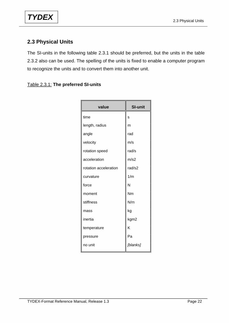
The SI-units in the following table 2.3.1 should be preferred, but the units in the table
2.3.2 also can be used. The spelling of the units is fixed to enable a computer program
to recognize the units and to convert them into another unit.
Table 2.3.1: The preferred SI-units
value SI-unit
time s
length, radius m
angle rad
velocity m/s
rotation speed rad/s
acceleration m/s2
rotation acceleration rad/s2
curvature 1/m
force N
moment Nm
stiffness N/m
mass kg
inertia kgm2
temperature K
pressure Pa
no unit [blanks]
TYDEX-Format Reference Manual, Release 1.3 Page 23
TYDEX 2.3 Physical Units
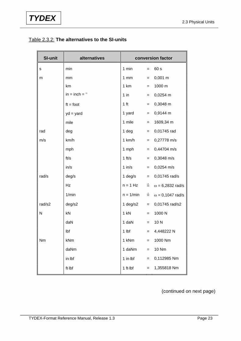
Table 2.3.2: The alternatives to the SI-units
SI-unit alternatives conversion factor
s min 1 min = 60 s
m mm 1 mm = 0,001 m
km 1 km = 1000 m
in = inch = ’’ 1 in = 0,0254 m
ft = foot 1 ft = 0,3048 m
yd = yard 1 yard = 0,9144 m
mile 1 mile = 1609,34 m
rad deg 1 deg = 0,01745 rad
m/s km/h 1 km/h = 0,27778 m/s
mph 1 mph = 0,44704 m/s
ft/s 1 ft/s = 0,3048 m/s
in/s 1 in/s = 0,0254 m/s
rad/s deg/s 1 deg/s = 0,01745 rad/s
Hz n = 1 Hz $= ω = 6,2832 rad/s
1/min n = 1/min $= ω = 0,1047 rad/s
rad/s2 deg/s2 1 deg/s2 = 0,01745 rad/s2
N kN 1 kN = 1000 N
daN 1 daN = 10 N
lbf 1 lbf = 4,448222 N
Nm kNm 1 kNm = 1000 Nm
daNm 1 daNm = 10 Nm
in⋅lbf 1 in⋅lbf = 0,112985 Nm
ft⋅lbf 1 ft⋅lbf = 1,355818 Nm
(continued on next page)
TYDEX-Format Reference Manual, Release 1.3 Page 24
TYDEX 2.3 Physical Units
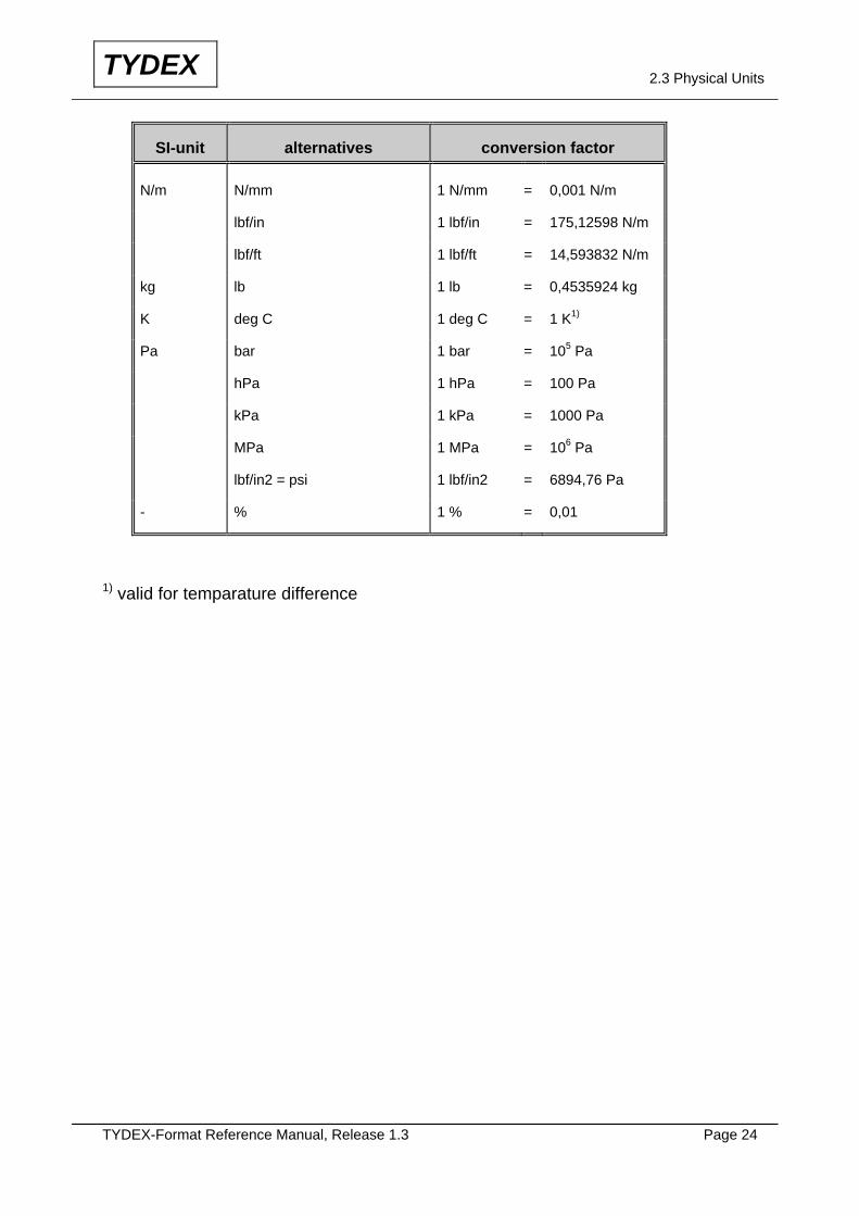
SI-unit alternatives conversion factor
N/m N/mm 1 N/mm = 0,001 N/m
lbf/in 1 lbf/in = 175,12598 N/m
lbf/ft 1 lbf/ft = 14,593832 N/m
kg lb 1 lb = 0,4535924 kg
K deg C 1 deg C = 1 K1)
Pa bar 1 bar = 105 Pa
hPa 1 hPa = 100 Pa
kPa 1 kPa = 1000 Pa
MPa 1 MPa = 106 Pa
lbf/in2 = psi 1 lbf/in2 = 6894,76 Pa
- % 1 % = 0,01
1) valid for temparature difference
TYDEX-Format Reference Manual, Release 1.3 Page 25
TYDEX 2.4 Examples
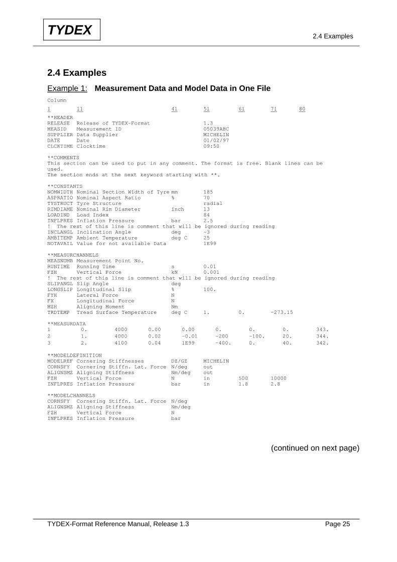
2.4 Examples Example 1: Measurement Data and Model Data in One File Column
1 11 41 51 61 71 80
**HEADER RELEASE Release of TYDEX-Format 1.3 MEASID Measurement ID 05039ABC SUPPLIER Data Supplier MICHELIN DATE Date 01/02/97 CLCKTIME Clocktime 09:50 **COMMENTS This section can be used to put in any comment. The format is free. Blank lines can be used. The section ends at the next keyword starting with **. **CONSTANTS NOMWIDTH Nominal Section Width of Tyre mm 185 ASPRATIO Nominal Aspect Ratio % 70 TYSTRUCT Tyre Structure radial RIMDIAME Nominal Rim Diameter inch 13 LOADIND Load Index 84 INFLPRES Inflation Pressure bar 2.5 ! The rest of this line is comment that will be ignored during reading INCLANGL Inclination Angle deg -3 AMBITEMP Ambient Temperature deg C 25 NOTAVAIL Value for not available Data 1E99 **MEASURCHANNELS MEASNUMB Measurement Point No. RUNTIME Running Time s 0.01 FZH Vertical Force kN 0.001 ! The rest of this line is comment that will be ignored during reading SLIPANGL Slip Angle deg LONGSLIP Longitudinal Slip % 100. FYH Lateral Force N FX Longitudinal Force N MZH Aligning Moment Nm TRDTEMP Tread Surface Temperature deg C 1. 0. -273.15 **MEASURDATA 1 0. 4000 0.00 0.00 0. 0. 0. 343. 2 1. 4000 0.02 -0.01 -200 -100. 20. 344. 3 2. 4100 0.04 1E99 -400. 0. 40. 342. **MODELDEFINITION MODELREF Cornering Stiffnesses DZ/GZ MICHELIN CORNSFY Cornering Stiffn. Lat. Force N/deg out ALIGNSMZ Aligning Stiffness Nm/deg out FZH Vertical Force N in 500 10000 INFLPRES Inflation Pressure bar in 1.8 2.8 **MODELCHANNELS CORNSFY Cornering Stiffn. Lat. Force N/deg ALIGNSMZ Aligning Stiffness Nm/deg FZH Vertical Force N INFLPRES Inflation Pressure bar
(continued on next page)
TYDEX-Format Reference Manual, Release 1.3 Page 26
TYDEX 2.4 Examples
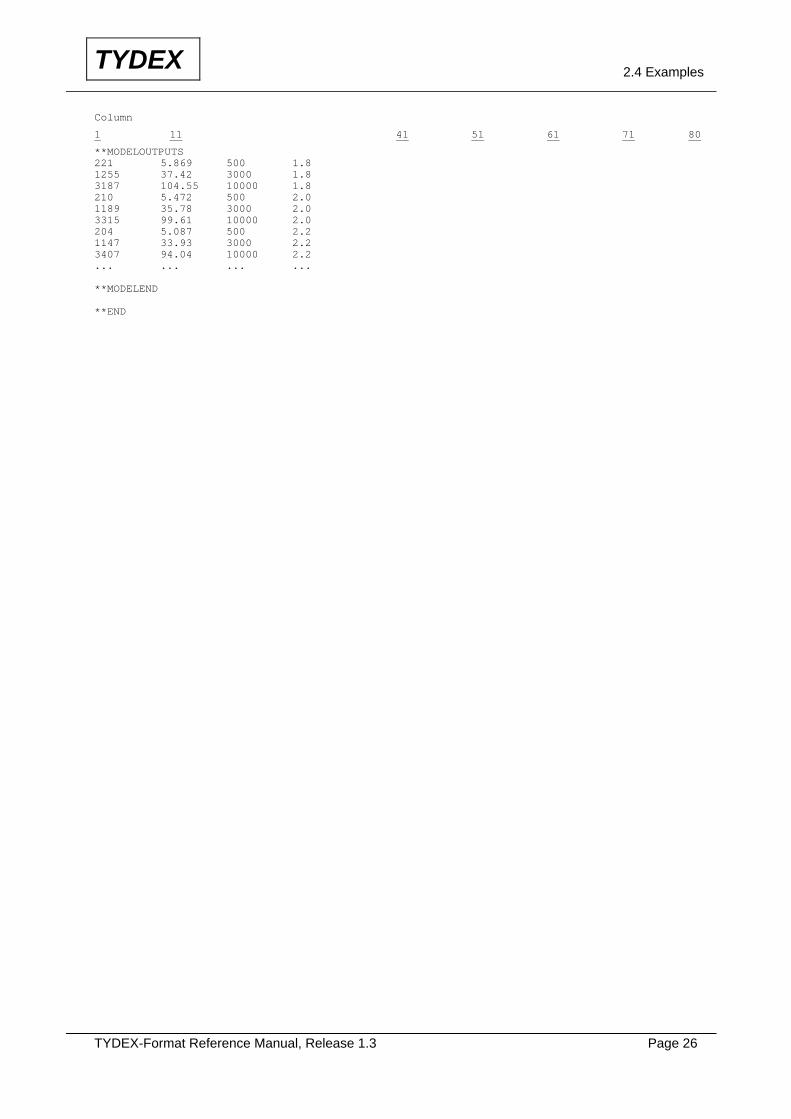
Column
1 11 41 51 61 71 80
**MODELOUTPUTS 221 5.869 500 1.8 1255 37.42 3000 1.8 3187 104.55 10000 1.8 210 5.472 500 2.0 1189 35.78 3000 2.0 3315 99.61 10000 2.0 204 5.087 500 2.2 1147 33.93 3000 2.2 3407 94.04 10000 2.2 ... ... ... ... **MODELEND **END
TYDEX-Format Reference Manual, Release 1.3 Page 27
TYDEX 2.4 Examples
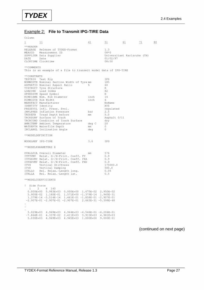
Example 2: File to Transmit IPG-TIRE Data Column
1 11 41 51 61 71 80
**HEADER RELEASE Release of TYDEX-Format 1.3 MEASID Measurement ID 08*0 SUPPLIER Data Supplier Universitaet Karlsruhe (TH) DATE Date 01/02/97 CLCKTIME Clocktime 08:50 **COMMENTS This is an example of a file to transmit model data of IPG-TIRE **CONSTANTS TESTRIG Test Rig IPS NOMWIDTH Nominal Section Width of Tyre mm 185 ASPRATIO Nominal Aspect Ratio % 60 TYSTRUCT Tyre Structure R LOADIND Load Index 82 SPEEDSYM Speed Symbol H RIMDIAME Nom. Rim Diameter inch 14 RIMWIDTH Rim Width inch 6 MANUFACT Manufacturer NoName IDENTITY Identity XYZ PRESEVOL Infl. Press. Evol. regulated INFLPRES Inflation Pressure bar 2.5 TRDDEPB Tread Depth before mm 5.0 TRCKSURF Surface of Track Asphalt 0/11 TRCKCOND Condition of Track Surface dry AMBITEMP Ambient Temperature deg C 20 WATDEPTH Waterfilm Depth mm 0 INCLANGL Inclination Angle deg 0 **MODELDEFINITION MODELREF IPG-TIRE 3.6 IPG **MODELPARAMETERS 8 OVALLDIA Overall Diameter mm 576 ITFYVMY Relat. G-/H-Frict. Coeff. FY 0.9 ITFXAVMY Relat. G-/H-Frict. Coeff. FXA 0.9 ITFXDVMY Relat. G-/H-Frict. Coeff. FXD 0.9 ITVS Vertical Stiffness 175000.0 ITVD Vertical Damping 500.0 ITRLLO Rel. Relax.-Length long. 0.05 ITRLLA Rel. Relax.-Length lat. 0.5 **MODELCOEFFICIENTS ! Side Force 1 2 6 140 0.000E+00 5.983E+03 0.000E+00 1.475E-02 2.950E-02 5.900E-02 1.180E-01 1.571E+00 -1.379E-14 1.945E-31 1.379E-14 -5.514E-14 1.461E-01 -1.858E-01 -2.907E-01 -2.907E-01 -2.907E-01 -2.907E-01 2.663E-31 -5.399E-48 . . . 5.029E+03 4.969E+03 4.944E+03 -4.546E-01 -6.206E-01 -7.866E-01 4.337E-02 2.411E+03 3.915E+03 4.981E+03 5.030E+03 4.969E+03 4.945E+03 1.000E+00 9.000E-01
(continued on next page)
TYDEX-Format Reference Manual, Release 1.3 Page 28
TYDEX 2.4 Examples
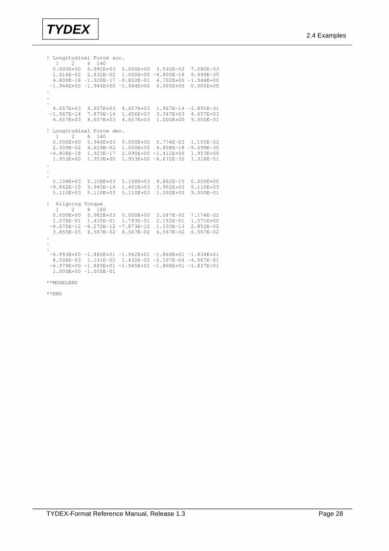
! Longitudinal Force acc. 1 2 6 140 0.000E+00 5.992E+03 0.000E+00 3.540E-03 7.080E-03 1.416E-02 2.832E-02 1.000E+00 -4.800E-18 9.499E-35 4.800E-18 -1.920E-17 -9.850E-01 4.702E+00 -1.944E+00 -1.944E+00 -1.944E+00 -1.944E+00 0.000E+00 0.000E+00 . . . 4.657E+03 4.657E+03 4.657E+03 1.967E-14 -3.891E-31 -1.967E-14 7.870E-14 1.456E+03 3.347E+03 4.657E+03 4.657E+03 4.657E+03 4.657E+03 1.000E+00 9.000E-01 ! Longitudinal Force dec. 1 2 6 140 0.000E+00 5.946E+03 0.000E+00 5.774E-03 1.155E-02 2.309E-02 4.619E-02 1.000E+00 4.808E-18 -9.499E-35 -4.808E-18 1.923E-17 2.090E+00 -1.412E+00 1.953E+00 1.953E+00 1.953E+00 1.953E+00 -6.672E-35 1.318E-51 . . . 5.108E+03 5.108E+03 5.108E+03 9.862E-15 0.000E+00 -9.862E-15 3.945E-14 1.401E+03 3.902E+03 5.110E+03 5.110E+03 5.110E+03 5.110E+03 1.000E+00 9.000E-01 ! Aligning Torque 1 2 8 160 0.000E+00 5.982E+03 0.000E+00 3.587E-02 7.174E-02 1.076E-01 1.435E-01 1.793E-01 2.152E-01 1.571E+00 -4.670E-12 -6.272E-12 -7.873E-12 1.333E-13 2.852E-02 3.855E-03 6.567E-02 6.567E-02 6.567E-02 6.567E-02 . . . -6.993E+00 -1.882E+01 -1.942E+01 -1.864E+01 -1.834E+01 8.506E-03 1.141E-02 1.432E-02 -2.107E-04 -4.567E-01 -6.979E+00 -1.885E+01 -1.945E+01 -1.868E+01 -1.837E+01 1.000E+00 -1.000E-01 **MODELEND **END
TYDEX-Format Reference Manual, Release 1.3 Page 29
TYDEX 2.4 Examples
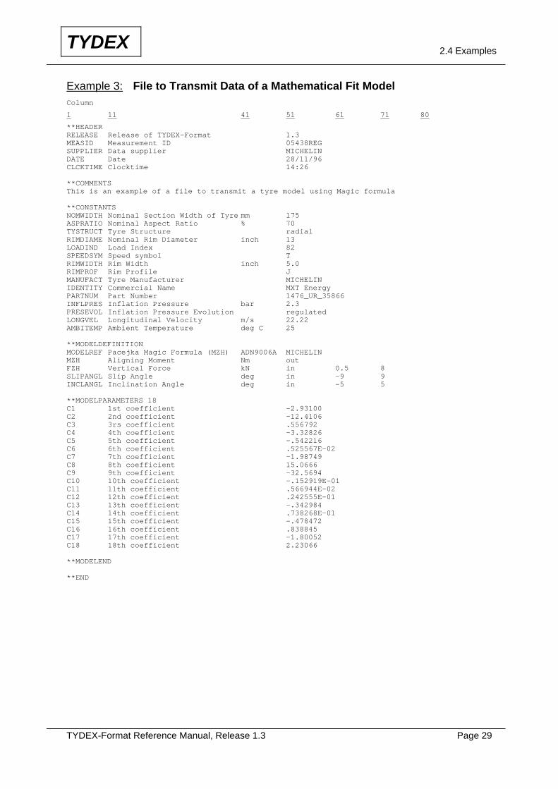
Example 3: File to Transmit Data of a Mathematical Fit Model Column
1 11 41 51 61 71 80
**HEADER RELEASE Release of TYDEX-Format 1.3 MEASID Measurement ID 05438REG SUPPLIER Data supplier MICHELIN DATE Date 28/11/96 CLCKTIME Clocktime 14:26 **COMMENTS This is an example of a file to transmit a tyre model using Magic formula **CONSTANTS NOMWIDTH Nominal Section Width of Tyre mm 175 ASPRATIO Nominal Aspect Ratio % 70 TYSTRUCT Tyre Structure radial RIMDIAME Nominal Rim Diameter inch 13 LOADIND Load Index 82 SPEEDSYM Speed symbol T RIMWIDTH Rim Width inch 5.0 RIMPROF Rim Profile J MANUFACT Tyre Manufacturer MICHELIN IDENTITY Commercial Name MXT Energy PARTNUM Part Number 1476_UR_35866 INFLPRES Inflation Pressure bar 2.3 PRESEVOL Inflation Pressure Evolution regulated LONGVEL Longitudinal Velocity m/s 22.22 AMBITEMP Ambient Temperature deg C 25 **MODELDEFINITION MODELREF Pacejka Magic Formula (MZH) ADN9006A MICHELIN MZH Aligning Moment Nm out FZH Vertical Force kN in 0.5 8 SLIPANGL Slip Angle deg in -9 9 INCLANGL Inclination Angle deg in -5 5 **MODELPARAMETERS 18 C1 1st coefficient -2.93100 C2 2nd coefficient -12.4106 C3 3rs coefficient .556792 C4 4th coefficient -3.32826 C5 5th coefficient -.542216 C6 6th coefficient .525567E-02 C7 7th coefficient -1.98749 C8 8th coefficient 15.0666 C9 9th coefficient -32.5694 C10 10th coefficient -.152919E-01 C11 11th coefficient .566944E-02 C12 12th coefficient .242555E-01 C13 13th coefficient -.342984 C14 14th coefficient .738268E-01 C15 15th coefficient -.478472 C16 16th coefficient .838845 C17 17th coefficient -1.80052 C18 18th coefficient 2.23066 **MODELEND **END
TYDEX-Format Reference Manual, Release 1.3 Page 30
TYDEX 2.4 Examples
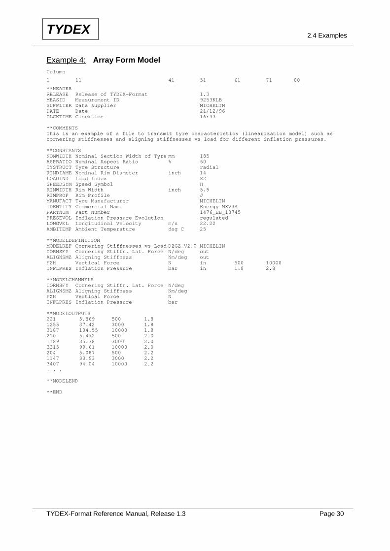
Example 4: Array Form Model Column
1 11 41 51 61 71 80
**HEADER RELEASE Release of TYDEX-Format 1.3 MEASID Measurement ID 9253KLB SUPPLIER Data supplier MICHELIN DATE Date 21/12/96 CLCKTIME Clocktime 16:33 **COMMENTS This is an example of a file to transmit tyre characteristics (linearization model) such as cornering stiffnesses and aligning stiffnesses vs load for different inflation pressures. **CONSTANTS NOMWIDTH Nominal Section Width of Tyre mm 185 ASPRATIO Nominal Aspect Ratio % 60 TYSTRUCT Tyre Structure radial RIMDIAME Nominal Rim Diameter inch 14 LOADIND Load Index 82 SPEEDSYM Speed Symbol H RIMWIDTH Rim Width inch 5.5 RIMPROF Rim Profile J MANUFACT Tyre Manufacturer MICHELIN IDENTITY Commercial Name Energy MXV3A PARTNUM Part Number 1476_EB_18745 PRESEVOL Inflation Pressure Evolution regulated LONGVEL Longitudinal Velocity m/s 22.22 AMBITEMP Ambient Temperature deg C 25 **MODELDEFINITION MODELREF Cornering Stiffnesses vs Load DZGZ_V2.0 MICHELIN CORNSFY Cornering Stiffn. Lat. Force N/deg out ALIGNSMZ Aligning Stiffness Nm/deg out FZH Vertical Force N in 500 10000 INFLPRES Inflation Pressure bar in 1.8 2.8 **MODELCHANNELS CORNSFY Cornering Stiffn. Lat. Force N/deg ALIGNSMZ Aligning Stiffness Nm/deg FZH Vertical Force N INFLPRES Inflation Pressure bar **MODELOUTPUTS 221 5.869 500 1.8 1255 37.42 3000 1.8 3187 104.55 10000 1.8 210 5.472 500 2.0 1189 35.78 3000 2.0 3315 99.61 10000 2.0 204 5.087 500 2.2 1147 33.93 3000 2.2 3407 94.04 10000 2.2 . . . **MODELEND **END

TYDEX-Format Reference Manual, Release 1.3 Page 31
TYDEX 2.4 Examples
Example 5: File to Transmit Data of a Physical Tyre Model Column
1 11 41 51 61 71 80
**HEADER RELEASE Release of TYDEX-Format 1.3 MEASID Measurement ID 5937URS SUPPLIER Data Supplier MICHELIN DATE Date 18/01/97 CLCKTIME Clocktime 08:56 **COMMENTS This is an example of a file to transmit a physical tyre model **CONSTANTS NOMWIDTH Nominal Section Width of Tyre mm 205 ASPRATIO Nominal Aspect Ratio % 60 TYSTRUCT Tyre Structure radial RIMDIAME Nominal Rim Diameter inch 15 LOADIND Load Index 90 SPEEDSYM Speed Symbol H RIMWIDTH Rim Width inch 6.0 RIMPROF Rim Profile J MANUFACT Tyre Manufacturer MICHELIN IDENTITY Commercial Name Energy MXV3A PARTNUM Part Number 7476_TR_87523 INFLPRES Inflation Pressure bar 2.4 PRESEVOL Inflation Pressure Evolution regulated LONGVEL Longitudinal Velocity m/s 1.0 AMBITEMP Ambient Temperature deg C 25 **MODELDEFINITION MODELREF Simple Brush/String Model Test_1 MICHELIN FYH Lateral Force N out FZH Vertical Force N in 1000 7000 SLIPANGL Slip Angle deg in -5 5 **MODELPARAMETERS 13 A 1st coef. cont. patch length m/N0.5 0.134E-2 B 2nd coef. cont. patch length m/N 0.419E-4 C Width of the cont. patch m 0.142 H0 Tread depth m 0.008 CSR Contact surface Ratio % 73 G Rubber shear modulus Pa 2.2E06 TAU Load distribution cont. patch 0.66 MU Adherence Coefficient 0.87 K6 Ply-steer Coefficient 1.942 ALPHA1 Ply-steer Angle deg 0.207 KY Lateral stiffness of the belt N/m 1.27E+5 S2 Lat. bending stiffn. of belt Nm 1.24E+4 T Torsional stiffness of belt Nm/rad 6855 **MODELEND **END
TYDEX-Format Reference Manual, Release 1.3 Page 32
TYDEX 2.4 Examples
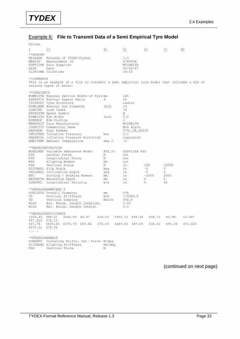
Example 6: File to Transmit Data of a Semi Empirical Tyre Model Column
1 11 41 51 61 71 80
**HEADER RELEASE Release of TYDEX-Format 1.3 MEASID Measurement ID 4789TGH SUPPLIER Data Supplier MICHELIN DATE Date 03/02/97 CLCKTIME Clocktime 18:55 **COMMENTS This is an example of a file to transmit a semi empirical tyre model that includes a mix of various types of datas. **CONSTANTS NOMWIDTH Nominal Section Width of Tyre mm 165 ASPRATIO Nominal Aspect Ratio % 65 TYSTRUCT Tyre Structure radial RIMDIAME Nominal Rim Diameter inch 13 LOADIND Load Index 76 SPEEDSYM Speed Symbol Q RIMWIDTH Rim Width inch 5.0 RIMPROF Rim Profile J MANUFACT Tyre Manufacturer MICHELIN IDENTITY Commercial Name M+S Alpin PARTNUM Part Number 5741_CB_84239 INFLPRES Inflation Pressure bar 2.1 PRESEVOL Inflation Pressure Evolution regulated AMBITEMP Ambient Temperature deg C -2 **MODELDEFINITION MODELREF Variable Adherence Model XYZ_V1 SUPPLIER XYZ FYH Lateral Force N out FXH Longitudinal Force N out MZH Aligning Moment Nm out FZH Vertical Force N in 100 10000 SLIPANGL Slip Angle deg in -5 5 INCLANGL Inclination Angle deg in -5 5 MYC Driving / Braking Moment Nm in -2000 2000 WATDEPTH Waterfilm Depth mm in 0 6 LONGVEL Longitudinal Velocity m/s in 0 40 **MODELPARAMETERS 5 OVALLDIA Overall Diameter mm 576 VS Vertical Stiffness N/m 175000.0 VD Vertical Damping Ns2/m 500.0 RLLO Rel. Relax. Length longitud. 0.05 RLLA Rel. Relax. Length lateral 0.5 **MODELCOEFFICIENTS 1024.45 399.21 3560.09 45.87 456.33 5902.10 498.34 638.71 63.98 12.587 457.025 478.12 567.78 5639.05 4378.78 653.82 375.19 4289.50 387.05 530.03 490.38 471.025 4573.01 578.34 . . . **MODELCHANNELS CORNSFY Cornering Stiffn. Lat. Force N/deg ALIGNSMZ Aligning Stiffness Nm/deg FZH Vertical Force N
(continued on next page)
TYDEX-Format Reference Manual, Release 1.3 Page 33
TYDEX 2.4 Examples
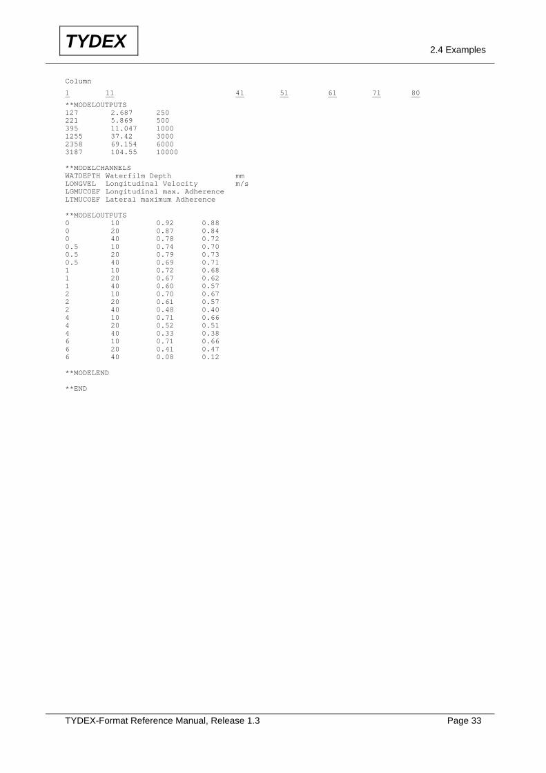
Column
1 11 41 51 61 71 80
**MODELOUTPUTS 127 2.687 250 221 5.869 500 395 11.047 1000 1255 37.42 3000 2358 69.154 6000 3187 104.55 10000 **MODELCHANNELS WATDEPTH Waterfilm Depth mm LONGVEL Longitudinal Velocity m/s LGMUCOEF Longitudinal max. Adherence LTMUCOEF Lateral maximum Adherence **MODELOUTPUTS 0 10 0.92 0.88 0 20 0.87 0.84 0 40 0.78 0.72 0.5 10 0.74 0.70 0.5 20 0.79 0.73 0.5 40 0.69 0.71 1 10 0.72 0.68 1 20 0.67 0.62 1 40 0.60 0.57 2 10 0.70 0.67 2 20 0.61 0.57 2 40 0.48 0.40 4 10 0.71 0.66 4 20 0.52 0.51 4 40 0.33 0.38 6 10 0.71 0.66 6 20 0.41 0.47 6 40 0.08 0.12 **MODELEND **END

TYDEX-Format Reference Manual, Release 1.3 Page 34
TYDEX 2.5 Parameter List
2.5 Parameter List Terms marked with Δ are standardized in ISO 8855 respectively DIN 70000. Terms marked with are completed according to ISO 8855 respectively DIN 70000. Terms marked with ◊ are standardized in ISO 3911. Terms marked with are used in ETRTO-Standard. Terms marked with are used in SAE J2047. Note:
The term WHEEL (RAD, ROUE) used in this TYDEX-Reference Manual is an abbreviation for the tyre - wheel assembly. The term WHEEL (RAD, ROUE) is capitalized in order to distinguish it from a related term "wheel" (Rad, roue), which is used for rim - disc assembly (see SAE J2047).
2.5.1 HEADER Abbrev. Parameter Unit Example (8 char.) (max. 29 characters) RELEASE release of TYDEX-format - 1.3 Version des TYDEX-Formats No. de vers. du TYDEX-format MEASID measurement id. - 05039ABC (local ident. format alphanumeric) Kennzahl der Messung numéro de la mesure SUPPLIER data supplier - MICHELIN (name of measurement supplier) Datenlieferant fournisseur de la mesure DATE date - 01/02/97 (format dd/mm/yy) Datum date CLCKTIME clocktime - 10:21 (format hh:mm) Uhrzeit heure
TYDEX-Format Reference Manual, Release 1.3 Page 35
TYDEX 2.5 Parameter List
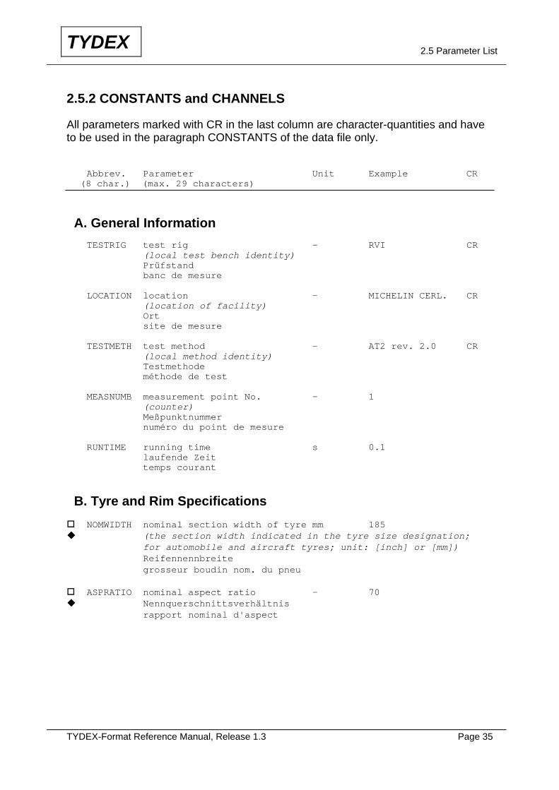
2.5.2 CONSTANTS and CHANNELS All parameters marked with CR in the last column are character-quantities and have to be used in the paragraph CONSTANTS of the data file only. Abbrev. Parameter Unit Example CR (8 char.) (max. 29 characters) A. General Information TESTRIG test rig - RVI CR (local test bench identity) Prüfstand banc de mesure LOCATION location - MICHELIN CERL. CR (location of facility) Ort site de mesure TESTMETH test method - AT2 rev. 2.0 CR (local method identity) Testmethode méthode de test MEASNUMB measurement point No. - 1 (counter) Meßpunktnummer numéro du point de mesure RUNTIME running time s 0.1 laufende Zeit temps courant
B. Tyre and Rim Specifications NOMWIDTH nominal section width of tyre mm 185 (the section width indicated in the tyre size designation;
for automobile and aircraft tyres; unit: [inch] or [mm]) Reifennennbreite grosseur boudin nom. du pneu ASPRATIO nominal aspect ratio - 70 Nennquerschnittsverhältnis
rapport nominal d'aspect
TYDEX-Format Reference Manual, Release 1.3 Page 36
TYDEX 2.5 Parameter List
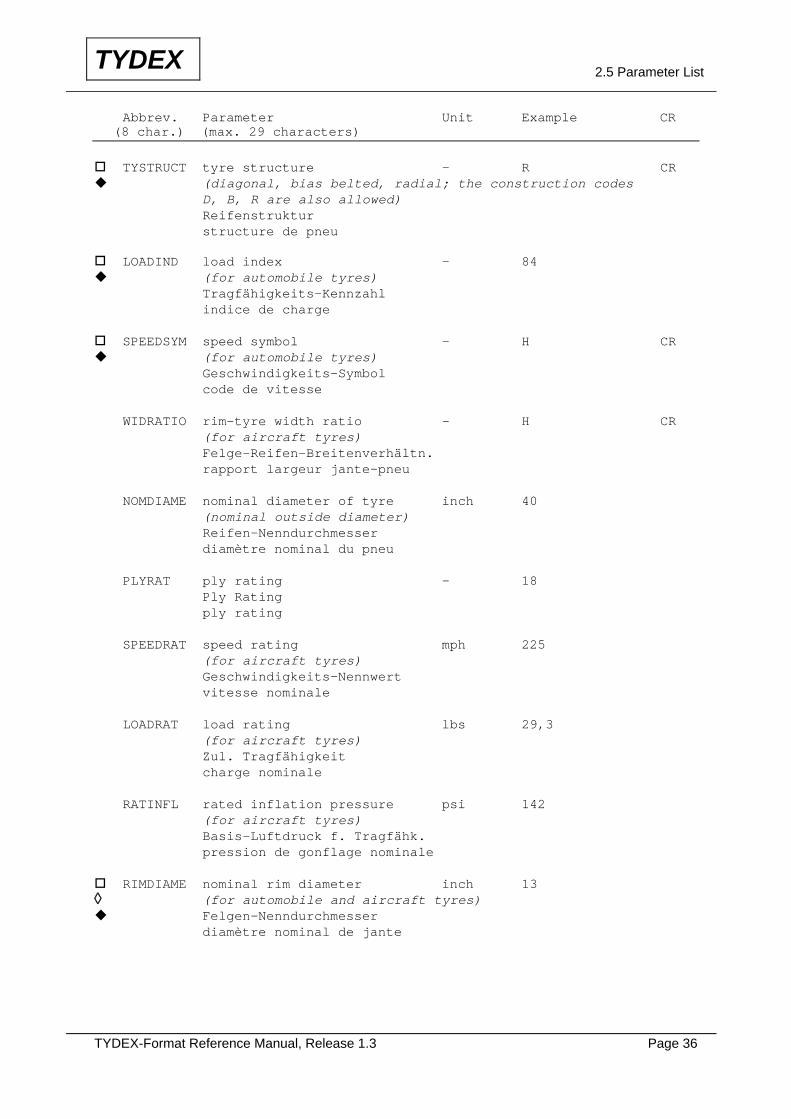
Abbrev. Parameter Unit Example CR (8 char.) (max. 29 characters) TYSTRUCT tyre structure - R CR (diagonal, bias belted, radial; the construction codes
D, B, R are also allowed) Reifenstruktur structure de pneu LOADIND load index - 84 (for automobile tyres)
Tragfähigkeits-Kennzahl indice de charge SPEEDSYM speed symbol - H CR (for automobile tyres)
Geschwindigkeits-Symbol code de vitesse WIDRATIO rim-tyre width ratio - H CR (for aircraft tyres) Felge-Reifen-Breitenverhältn. rapport largeur jante-pneu NOMDIAME nominal diameter of tyre inch 40 (nominal outside diameter) Reifen-Nenndurchmesser diamètre nominal du pneu PLYRAT ply rating - 18 Ply Rating ply rating SPEEDRAT speed rating mph 225 (for aircraft tyres) Geschwindigkeits-Nennwert vitesse nominale LOADRAT load rating lbs 29,3 (for aircraft tyres) Zul. Tragfähigkeit charge nominale RATINFL rated inflation pressure psi 142 (for aircraft tyres) Basis-Luftdruck f. Tragfähk. pression de gonflage nominale RIMDIAME nominal rim diameter inch 13
◊ (for automobile and aircraft tyres) Felgen-Nenndurchmesser
diamètre nominal de jante
TYDEX-Format Reference Manual, Release 1.3 Page 37
TYDEX 2.5 Parameter List
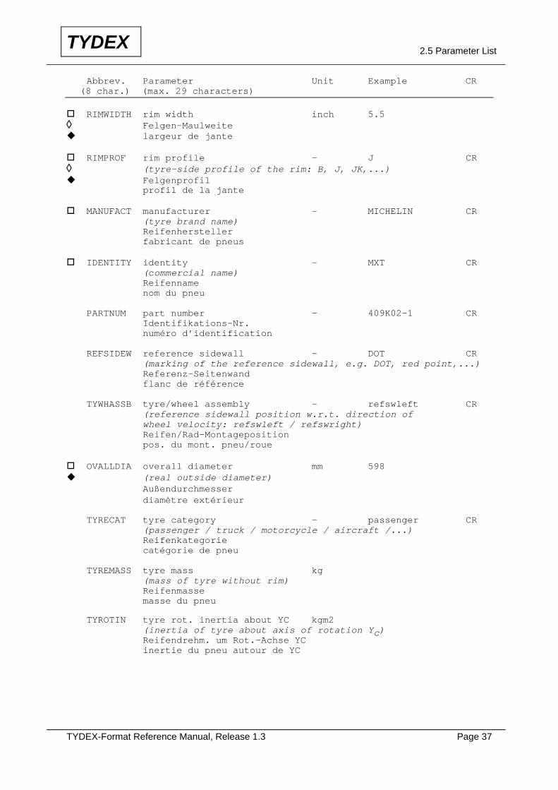
Abbrev. Parameter Unit Example CR (8 char.) (max. 29 characters) RIMWIDTH rim width inch 5.5
◊ Felgen-Maulweite largeur de jante
RIMPROF rim profile - J CR
◊ (tyre-side profile of the rim: B, J, JK,...) Felgenprofil
profil de la jante MANUFACT manufacturer - MICHELIN CR
(tyre brand name) Reifenhersteller fabricant de pneus IDENTITY identity - MXT CR
(commercial name) Reifenname nom du pneu PARTNUM part number - 409K02-1 CR Identifikations-Nr. numéro d’identification REFSIDEW reference sidewall - DOT CR (marking of the reference sidewall, e.g. DOT, red point,...) Referenz-Seitenwand flanc de référence TYWHASSB tyre/wheel assembly - refswleft CR (reference sidewall position w.r.t. direction of wheel velocity: refswleft / refswright) Reifen/Rad-Montageposition pos. du mont. pneu/roue OVALLDIA overall diameter mm 598 (real outside diameter)
Außendurchmesser diamètre extérieur TYRECAT tyre category - passenger CR (passenger / truck / motorcycle / aircraft /...) Reifenkategorie catégorie de pneu TYREMASS tyre mass kg (mass of tyre without rim) Reifenmasse masse du pneu TYROTIN tyre rot. inertia about YC kgm2 (inertia of tyre about axis of rotation Yc) Reifendrehm. um Rot.-Achse YC inertie du pneu autour de YC
TYDEX-Format Reference Manual, Release 1.3 Page 38
TYDEX 2.5 Parameter List
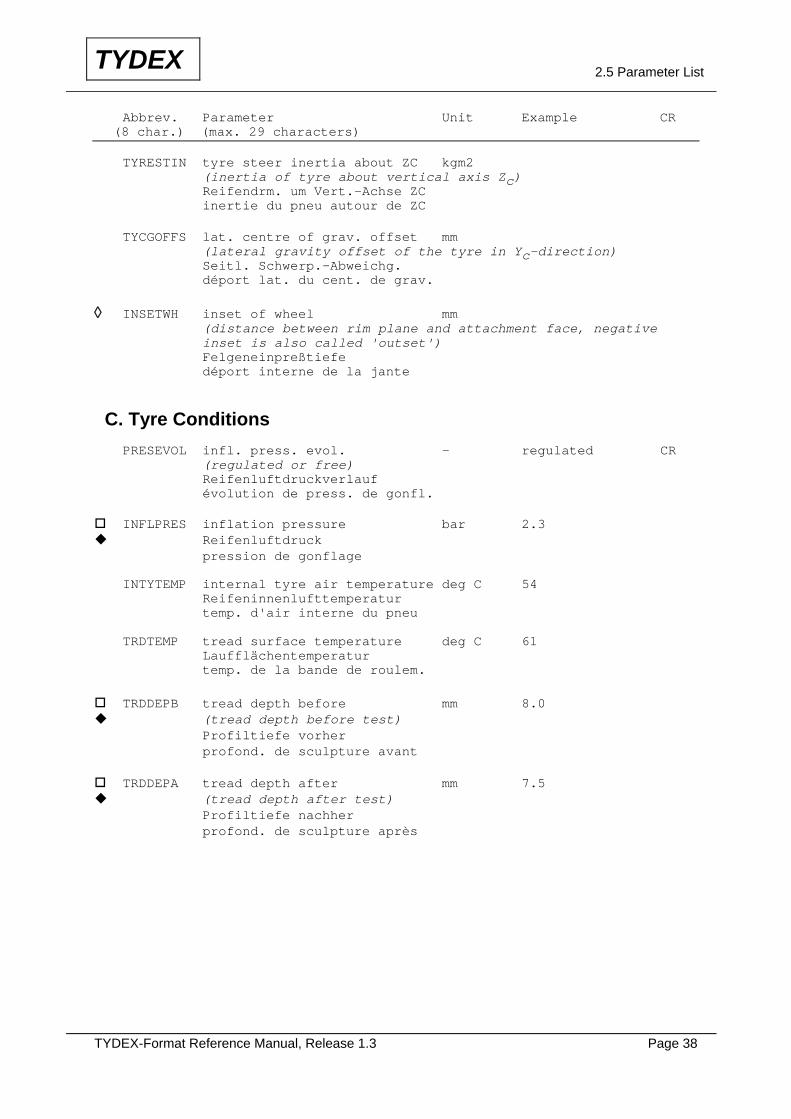
Abbrev. Parameter Unit Example CR (8 char.) (max. 29 characters) TYRESTIN tyre steer inertia about ZC kgm2 (inertia of tyre about vertical axis Zc) Reifendrm. um Vert.-Achse ZC inertie du pneu autour de ZC TYCGOFFS lat. centre of grav. offset mm (lateral gravity offset of the tyre in Yc-direction) Seitl. Schwerp.-Abweichg. déport lat. du cent. de grav.
◊ INSETWH inset of wheel mm (distance between rim plane and attachment face, negative inset is also called 'outset') Felgeneinpreßtiefe déport interne de la jante
C. Tyre Conditions PRESEVOL infl. press. evol. - regulated CR (regulated or free) Reifenluftdruckverlauf évolution de press. de gonfl. INFLPRES inflation pressure bar 2.3 Reifenluftdruck
pression de gonflage INTYTEMP internal tyre air temperature deg C 54 Reifeninnenlufttemperatur temp. d'air interne du pneu TRDTEMP tread surface temperature deg C 61 Laufflächentemperatur temp. de la bande de roulem. TRDDEPB tread depth before mm 8.0 (tread depth before test)
Profiltiefe vorher profond. de sculpture avant TRDDEPA tread depth after mm 7.5 (tread depth after test)
Profiltiefe nachher profond. de sculpture après
TYDEX-Format Reference Manual, Release 1.3 Page 39
TYDEX 2.5 Parameter List
Abbrev. Parameter Unit Example CR (8 char.) (max. 29 characters)
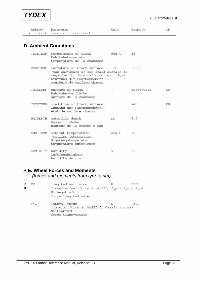
D. Ambient Conditions TRCKTEMP temperature of track deg C 22 Fahrbahntemperatur température de la chaussée CURVTRSF curvature of track surface 1/m -0.526 (the curvature of the track surface is negative for internal drum test rigs) Krümmung der Fahrbahnoberfl. courbure de surface chauss. TRCKSURF surface of track - safetywalk CR Fahrbahnoberfläche surface de la chaussée TRCKCOND condition of track surface - wet CR Zustand der Fahrbahnoberfl. état de surface chauss. WATDEPTH waterfilm depth mm 3.0 Wasserfilmhöhe hauteur de la couche d'eau AMBITEMP ambient temperature deg C 20 (outside temperature) Umgebungstemperatur température extérieure HUMIDITY humidity % 60 Luftfeuchtigkeit humidité de l'air
Δ E. Wheel Forces and Moments (forces and moments from tyre to rim) Δ FX longitudinal force N 2000 (longitudinal force at WHEEL, FXC = FXH = FXW)
Umfangskraft force longitudinale FYC lateral force N 1500 (lateral force at WHEEL in C-axis system) Seitenkraft force transversale
TYDEX-Format Reference Manual, Release 1.3 Page 40
TYDEX 2.5 Parameter List
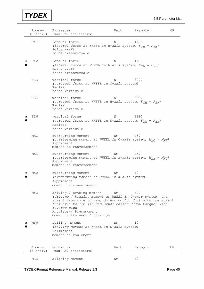
Abbrev. Parameter Unit Example CR (8 char.) (max. 29 characters) FYH lateral force N 1605 (lateral force at WHEEL in H-axis system, FYH = FYW) Seitenkraft force transversale Δ FYW lateral force N 1605 (lateral force at WHEEL in W-axis system, FYW = FYH)
Seitenkraft force transversale FZC vertical force N 3000 (vertical force at WHEEL in C-axis system) Radlast force verticale FZH vertical force N 2990 (vertical force at WHEEL in H-axis system, FZH = FZW) Radlast force verticale Δ FZW vertical force N 2990 (vertical force at WHEEL in W-axis system, FZW = FZH)
Radlast force verticale MXC overturning moment Nm 450 (overturning moment at WHEEL in C-axis system, MXC = MXH) Kippmoment moment de renversement MXH overturning moment Nm 450 (overturning moment at WHEEL in H-axis system, MXH = MXC) Kippmoment moment de renversement Δ MXW overturning moment Nm 60 (overturning moment at WHEEL in W-axis system)
Kippmoment moment de renversement MYC driving / braking moment Nm 600 (driving / braking moment at WHEEL in C-axis system, the moment from tyre to rim; do not confound it with the moment from axle to rim (in SAE J2047 called WHEEL torque) with reverse sign) Antriebs-/ Bremsmoment moment entrainem. / freinage Δ MYW rolling moment Nm 10 (rolling moment at WHEEL in W-axis system)
Rollmoment moment de roulement Abbrev. Parameter Unit Example CR (8 char.) (max. 29 characters) MZC aligning moment Nm 60
TYDEX-Format Reference Manual, Release 1.3 Page 41
TYDEX 2.5 Parameter List
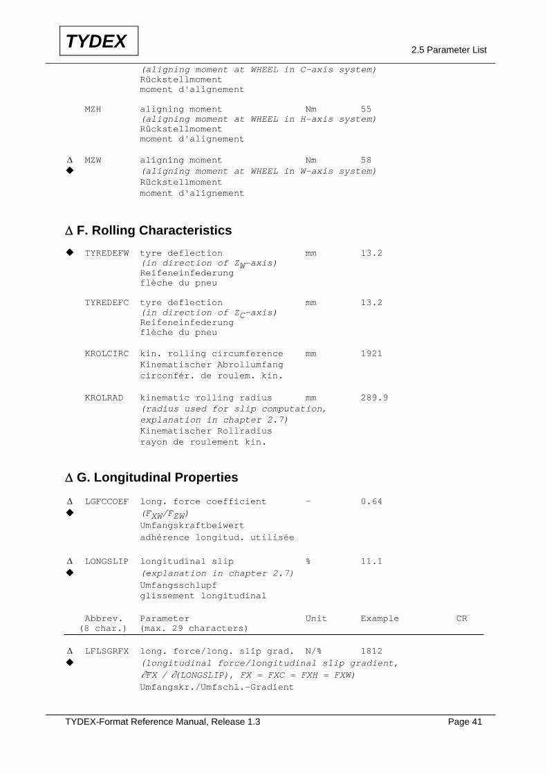
(aligning moment at WHEEL in C-axis system) Rückstellmoment moment d'alignement MZH aligning moment Nm 55 (aligning moment at WHEEL in H-axis system) Rückstellmoment moment d'alignement Δ MZW aligning moment Nm 58 (aligning moment at WHEEL in W-axis system)
Rückstellmoment moment d'alignement
Δ F. Rolling Characteristics TYREDEFW tyre deflection mm 13.2
(in direction of ZW-axis) Reifeneinfederung flèche du pneu TYREDEFC tyre deflection mm 13.2 (in direction of ZC-axis) Reifeneinfederung flèche du pneu KROLCIRC kin. rolling circumference mm 1921 Kinematischer Abrollumfang circonfér. de roulem. kin. KROLRAD kinematic rolling radius mm 289.9 (radius used for slip computation, explanation in chapter 2.7) Kinematischer Rollradius rayon de roulement kin.
Δ G. Longitudinal Properties
Δ LGFCCOEF long. force coefficient - 0.64 (FXW/FZW)
Umfangskraftbeiwert adhérence longitud. utilisée
Δ LONGSLIP longitudinal slip % 11.1 (explanation in chapter 2.7)
Umfangsschlupf glissement longitudinal Abbrev. Parameter Unit Example CR (8 char.) (max. 29 characters) Δ LFLSGRFX long. force/long. slip grad. N/% 1812 (longitudinal force/longitudinal slip gradient,
∂ ∂FX LONGSLIP/ ( ), FX = FXC = FXH = FXW) Umfangskr./Umfschl.-Gradient

TYDEX-Format Reference Manual, Release 1.3 Page 42
TYDEX 2.5 Parameter List
grad. de la force longitudin. (gradient de la force longitudinale à la roue par rapport au glissement longitudinal, rigidité de pseudo-glissement longitudinal)
H. Lateral Properties
Δ LTFCCOEF lateral force coefficient - 0.59 (FYW/FZW)
Seitenkraftbeiwert adhérence latérale utilisée
Δ SLIPANGL slip angle deg 8 (angle from the XW-axis to the tangent to the trajectory of
the WHEEL intersection point (origin of W-axis system)) Schräglaufwinkel angle de dérive du pneu Δ CORNSFY cornering stiffn. lat. force N/deg 1702 (cornering stiffness, −∂ ∂FY SLIPANGL/ ( ))
Seitenkr.-Schräglw.-Gradient raideur de dérive fce. trnsv. (rigidité de poussée de dérive) ALIGNSMZ aligning stiffness Nm/deg 77.4
(∂ ∂MZ SLIPANGL/ ( )) Rückstm.-Schräglw.-Gradient rig. couple autoalign. dérive (rigidité de couple d’autoalignement en dérive) Δ CAMBSFY camber stiffness lat. force N/deg 41.7 ( −∂ ∂FY INCLANGL/ ( ))
Seitenkr.-Radsturzw.-Gradient raideur de carrossage (rigidité de poussée de carrossage) CAMBSMZ camber stiffn. aligning mom. Nm/deg 1.3 (∂ ∂MZ INCLANGL/ ( ) ) Rückstm.-Radsturzw.-Gradient rig. couple autoalign. carr. (rigidité de couple d’autoalignement en carrossage)
TYDEX-Format Reference Manual, Release 1.3 Page 43
TYDEX 2.5 Parameter List
Abbrev. Parameter Unit Example CR (8 char.) (max. 29 characters)
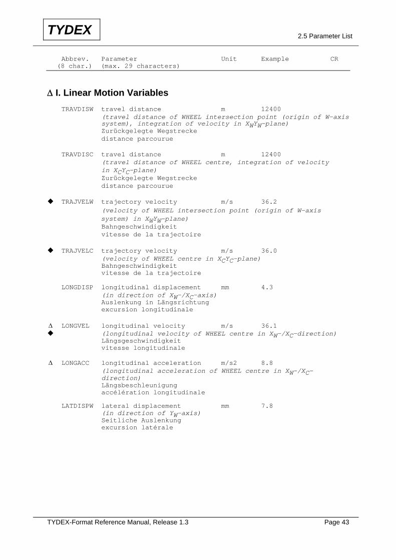
Δ I. Linear Motion Variables TRAVDISW travel distance m 12400 (travel distance of WHEEL intersection point (origin of W-axis system), integration of velocity in XWYW-plane) Zurückgelegte Wegstrecke distance parcourue TRAVDISC travel distance m 12400 (travel distance of WHEEL centre, integration of velocity in XCYC-plane) Zurückgelegte Wegstrecke distance parcourue
TRAJVELW trajectory velocity m/s 36.2 (velocity of WHEEL intersection point (origin of W-axis system) in XWYW-plane) Bahngeschwindigkeit vitesse de la trajectoire TRAJVELC trajectory velocity m/s 36.0
(velocity of WHEEL centre in XCYC-plane) Bahngeschwindigkeit vitesse de la trajectoire LONGDISP longitudinal displacement mm 4.3 (in direction of XW-/XC-axis) Auslenkung in Längsrichtung excursion longitudinale Δ LONGVEL longitudinal velocity m/s 36.1 (longitudinal velocity of WHEEL centre in XW-/XC-direction)
Längsgeschwindigkeit vitesse longitudinale Δ LONGACC longitudinal acceleration m/s2 8.8 (longitudinal acceleration of WHEEL centre in XW-/XC- direction) Längsbeschleunigung accélération longitudinale LATDISPW lateral displacement mm 7.8 (in direction of YW-axis) Seitliche Auslenkung excursion latérale
TYDEX-Format Reference Manual, Release 1.3 Page 44
TYDEX 2.5 Parameter List
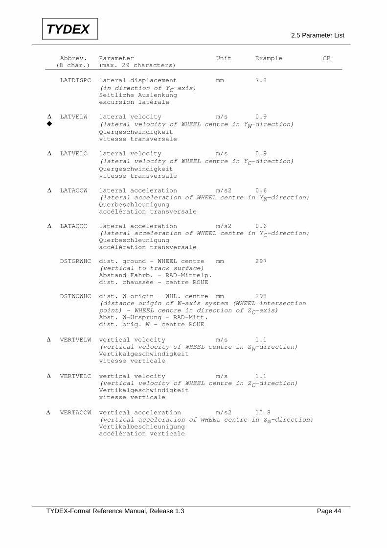
Abbrev. Parameter Unit Example CR (8 char.) (max. 29 characters) LATDISPC lateral displacement mm 7.8 (in direction of YC-axis) Seitliche Auslenkung excursion latérale Δ LATVELW lateral velocity m/s 0.9 (lateral velocity of WHEEL centre in YW-direction)
Quergeschwindigkeit vitesse transversale Δ LATVELC lateral velocity m/s 0.9 (lateral velocity of WHEEL centre in YC-direction) Quergeschwindigkeit vitesse transversale Δ LATACCW lateral acceleration m/s2 0.6 (lateral acceleration of WHEEL centre in YW-direction) Querbeschleunigung accélération transversale Δ LATACCC lateral acceleration m/s2 0.6 (lateral acceleration of WHEEL centre in YC-direction) Querbeschleunigung accélération transversale DSTGRWHC dist. ground - WHEEL centre mm 297 (vertical to track surface) Abstand Fahrb. - RAD-Mittelp. dist. chaussée - centre ROUE DSTWOWHC dist. W-origin - WHL. centre mm 298 (distance origin of W-axis system (WHEEL intersection point) - WHEEL centre in direction of ZC-axis) Abst. W-Ursprung - RAD-Mitt. dist. orig. W - centre ROUE Δ VERTVELW vertical velocity m/s 1.1 (vertical velocity of WHEEL centre in ZW-direction) Vertikalgeschwindigkeit vitesse verticale Δ VERTVELC vertical velocity m/s 1.1 (vertical velocity of WHEEL centre in ZC-direction) Vertikalgeschwindigkeit vitesse verticale Δ VERTACCW vertical acceleration m/s2 10.8 (vertical acceleration of WHEEL centre in ZW-direction) Vertikalbeschleunigung accélération verticale
TYDEX-Format Reference Manual, Release 1.3 Page 45
TYDEX 2.5 Parameter List
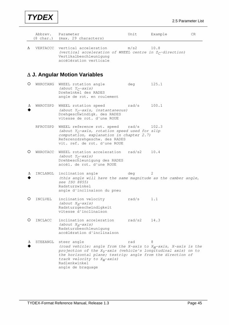
Abbrev. Parameter Unit Example CR (8 char.) (max. 29 characters) Δ VERTACCC vertical acceleration m/s2 10.8 (vertical acceleration of WHEEL centre in ZC-direction) Vertikalbeschleunigung accélération verticale
Δ J. Angular Motion Variables WHROTANG WHEEL rotation angle deg 125.1
(about YC-axis) Drehwinkel des RADES angle de rot. en roulement Δ WHROTSPD WHEEL rotation speed rad/s 100.1 (about YC-axis, instantaneous)
Drehgeschwindigk. des RADES vitesse de rot. d'une ROUE RFROTSPD WHEEL reference rot. speed rad/s 102.3 (about YC-axis, rotation speed used for slip computation, explanation in chapter 2.7) Referenzdrehgeschw. des RADES vit. ref. de rot. d'une ROUE WHROTACC WHEEL rotation acceleration rad/s2 10.4
(about YC-axis) Drehbeschleunigung des RADES accél. de rot. d'une ROUE Δ INCLANGL inclination angle deg 2 (this angle will have the same magnitude as the camber angle,
see ISO 8855) Radsturzwinkel angle d'inclinaison du pneu INCLVEL inclination velocity rad/s 1.1
(about XH-axis) Radsturzgeschwindigkeit vitesse d'inclinaison INCLACC inclination acceleration rad/s2 14.3
(about XH-axis) Radsturzbeschleunigung accélération d'inclinaison Δ STEEANGL steer angle rad 8 (road vehicle: angle from the X-axis to XW-axis, X-axis is the
projection of the XV-axis (vehicle's longitudinal axis) on to the horizontal plane; testrig: angle from the direction of track velocity to XW-axis) Radlenkwinkel angle de braquage
TYDEX-Format Reference Manual, Release 1.3 Page 46
TYDEX 2.5 Parameter List
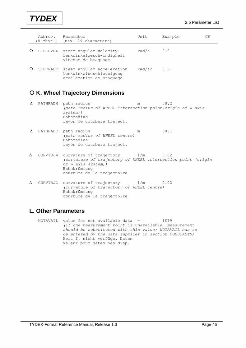
Abbrev. Parameter Unit Example CR (8 char.) (max. 29 characters) STEERVEL steer angular velocity rad/s 0.8
Lenkwinkelgeschwindigkeit vitesse de braquage STEERACC steer angular acceleration rad/s2 0.6
Lenkwinkelbeschleunigung accélération de braquage
K. Wheel Trajectory Dimensions Δ PATHRADW path radius m 50.2 (path radius of WHEEL intersection point(origin of W-axis system)) Bahnradius rayon de courbure traject. Δ PATHRADC path radius m 50.1 (path radius of WHEEL centre) Bahnradius rayon de courbure traject. Δ CURVTRJW curvature of trajectory 1/m 0.02 (curvature of trajectory of WHEEL intersection point (origin of W-axis system)) Bahnkrümmung courbure de la trajectoire Δ CURVTRJC curvature of trajectory 1/m 0.02 (curvature of trajectory of WHEEL centre) Bahnkrümmung courbure de la trajectoire
L. Other Parameters NOTAVAIL value for not available data - 1E99 (if one measurement point is unavailable, measurement should be substituted with this value; NOTAVAIL has to be entered by the data supplier in section CONSTANTS) Wert f. nicht verfügb. Daten valeur pour dates pas disp.
TYDEX-Format Reference Manual, Release 1.3 Page 47
TYDEX 2.6 Axis Systems
2.6 Axis Systems
For the TYDEX-data files three right-hand orthogonal axis systems are defined.
These axis systems are explained in the following chapters. In each respective
illustration are shown
- a positive slip angle α,
- a positive inclination angle γ and
- a positive wheel rotation speed ω.
Note: The inclination angle is called inclination angle γ in SAE J2047 and inclination
angle εW in ISO 8855.
It is permissible to use both symbols in context with the TYDEX-Format.
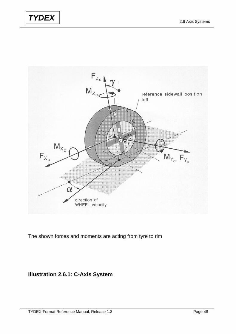
2.6.1 C-Axis System
The C-axis system (centre axis system) is shown in illustration 2.6.1. The origin of
this axis system is fixed in the centre of the WHEEL.
The XC-axis is in the central plane of the WHEEL and is parallel to the ground.
The YC-axis turns with the inclination angle γ. It is identical with the spin axis of the
WHEEL.
The ZC-axis points upwards and also turns with the inclination angle γ. It is in the
central plane of the WHEEL.
Note: In SAE J2047 a C-axis system (WHEEL center system) is also defined. The
orientation of this axis system corresponds to the TYDEX C-axis system, but
in SAE J2047 the axis system is shown without inclination angle.
TYDEX-Format Reference Manual, Release 1.3 Page 48
TYDEX 2.6 Axis Systems
The shown forces and moments are acting from tyre to rim Illustration 2.6.1: C-Axis System
TYDEX-Format Reference Manual, Release 1.3 Page 49
TYDEX 2.6 Axis Systems
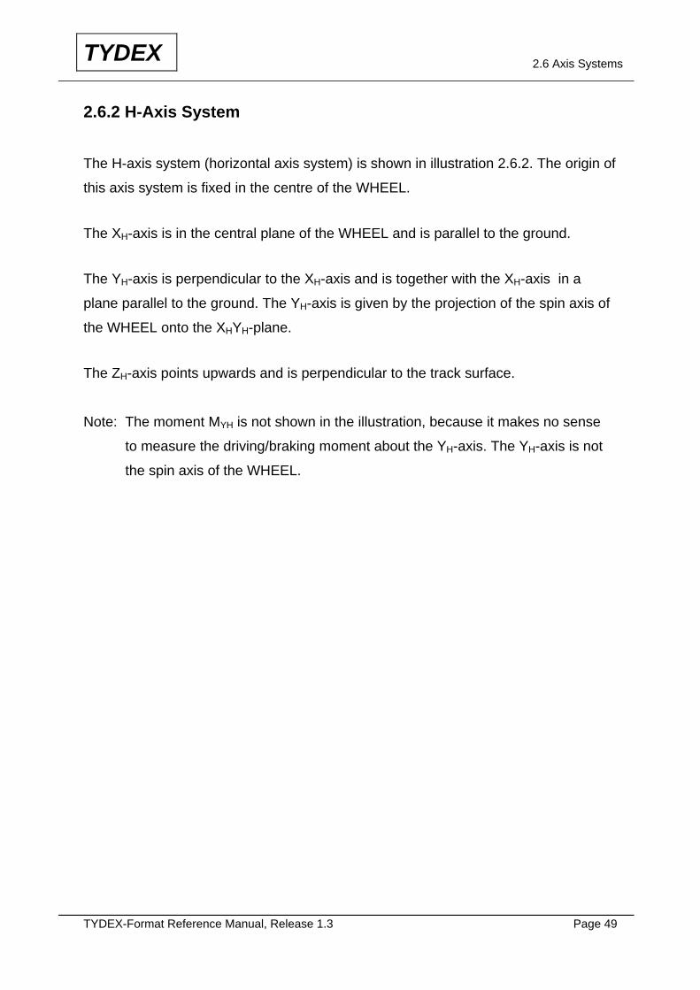
2.6.2 H-Axis System
The H-axis system (horizontal axis system) is shown in illustration 2.6.2. The origin of
this axis system is fixed in the centre of the WHEEL.
The XH-axis is in the central plane of the WHEEL and is parallel to the ground.
The YH-axis is perpendicular to the XH-axis and is together with the XH-axis in a
plane parallel to the ground. The YH-axis is given by the projection of the spin axis of
the WHEEL onto the XHYH-plane.
The ZH-axis points upwards and is perpendicular to the track surface.
Note: The moment MYH is not shown in the illustration, because it makes no sense
to measure the driving/braking moment about the YH-axis. The YH-axis is not
the spin axis of the WHEEL.
TYDEX-Format Reference Manual, Release 1.3 Page 50
TYDEX 2.6 Axis Systems
The shown forces and moments are acting from tyre to rim Illustration 2.6.2: H-Axis System
TYDEX-Format Reference Manual, Release 1.3 Page 51
TYDEX 2.6 Axis Systems
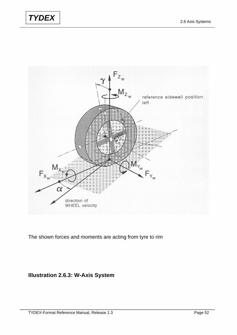
2.6.3 W-Axis System
The W-axis system (WHEEL axis system) is standardized in ISO 8855 and is shown
in illustration 2.6.3.
In ISO the track surface is defined as horizontal (horizontal plane = ground plane),
but in this TYDEX Axis System also a sloped ground is permissible.
The XW-axis is given by the intersection of the central plane of the WHEEL with the
track surface.
The YW-axis is given by the projection of the spin axis onto the ground.
The ZW-axis is normal to the ground and points upwards.
The origin of the W-axis system is also called "WHEEL intersection point" in this
TYDEX-Reference Manual.
TYDEX-Format Reference Manual, Release 1.3 Page 52
TYDEX 2.6 Axis Systems
The shown forces and moments are acting from tyre to rim Illustration 2.6.3: W-Axis System
TYDEX-Format Reference Manual, Release 1.3 Page 53
TYDEX 2.7 Longitudinal Slip
2.7 Longitudinal Slip
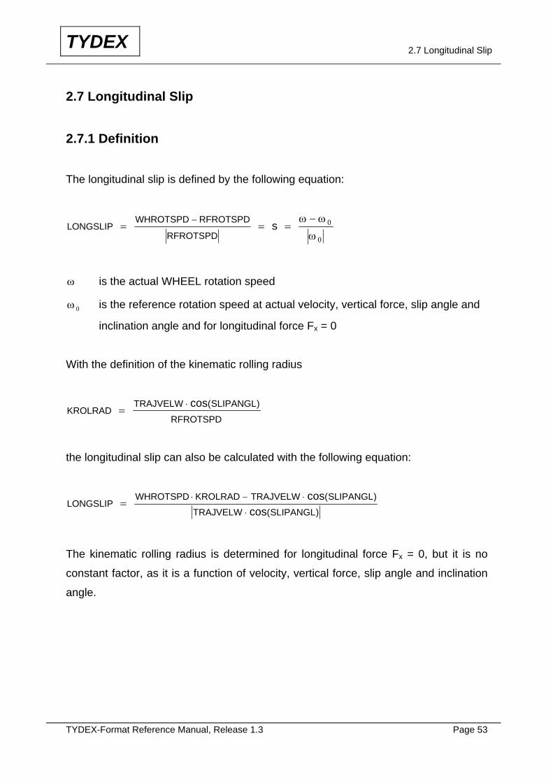
2.7.1 Definition
The longitudinal slip is defined by the following equation:
LONGSLIPWHROTSPD RFROTSPD
RFROTSPDs= = =
−− ω ω
ω0
0
ω is the actual WHEEL rotation speed
ω 0 is the reference rotation speed at actual velocity, vertical force, slip angle and
inclination angle and for longitudinal force Fx = 0
With the definition of the kinematic rolling radius
KROLRADTRAJVELW SLIPANGL
RFROTSPD=
⋅ cos( )
the longitudinal slip can also be calculated with the following equation:
LONGSLIPWHROTSPD KROLRAD TRAJVELW SLIPANGL
TRAJVELW SLIPANGL=
⋅ − ⋅
⋅
coscos
( )
( )
The kinematic rolling radius is determined for longitudinal force Fx = 0, but it is no
constant factor, as it is a function of velocity, vertical force, slip angle and inclination
angle.
TYDEX-Format Reference Manual, Release 1.3 Page 54
TYDEX 2.7 Longitudinal Slip
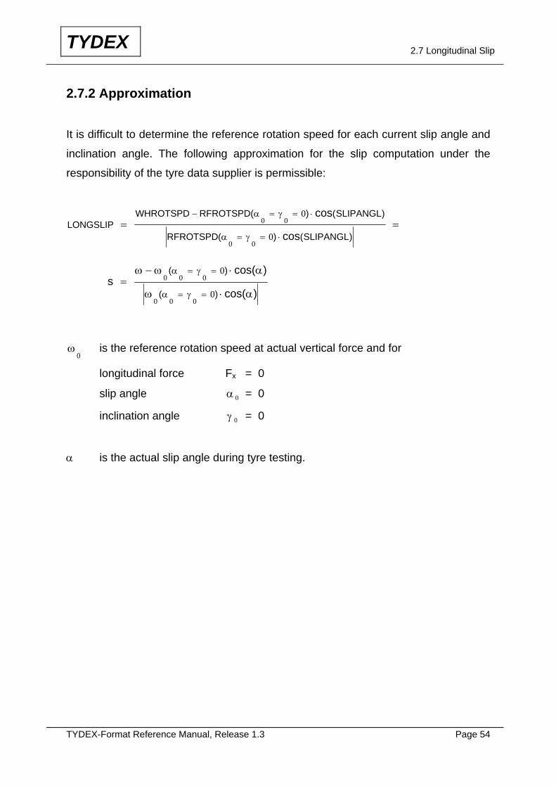
2.7.2 Approximation
It is difficult to determine the reference rotation speed for each current slip angle and
inclination angle. The following approximation for the slip computation under the
responsibility of the tyre data supplier is permissible:
LONGSLIPRFROTSPD SLIPANGL
RFROTSPD SLIPANGL= =
− = = ⋅
= = ⋅
WHROTSPD ( ) ( )
( ) ( )
cos
cos
α γ
α γ
0 0
0 0
0
0
s =− ⋅
⋅
= =
= =
ω ω α
ω α
α γ
α γ
0 0 0
0 0 0
0
0
( )
( )
cos( )
cos( )
ω0 is the reference rotation speed at actual vertical force and for
longitudinal force Fx = 0
slip angle α 0 = 0
inclination angle γ 0 = 0
α is the actual slip angle during tyre testing.
TYDEX-Format Reference Manual, Release 1.3 Page 55
TYDEX 3. Literature
3. Literature ISO 3911 Wheels/rims - Nomenclature, designation, marking and units of measurement, 1977 ISO 8855 Road vehicles - Vehicle dynamics and road-holding ability - Vocabulary, 1991 DIN 70000 Straßenfahrzeuge - Fahrdynamik und Fahrverhalten - Begriffe, 1994 ETRTO Engineering Design Information, 1994 ETRTO Standards Manual, 1994 ETRTO Technical Dictionary, 1993 SAE J2047 Surface Vehicle Information Report, Proposed Draft June 1994