Embed Size (px)
Citation preview

®
©Copyright 2008. All Rights Reserved
User Manual Product Model: xStack® DES-3500 Series
Layer 2 Managed Stackable Fast Ethernet Switch
Release 5.1

ii
__________________________________________________________________________________ Information in this document is subject to change without notice. © 2008 D-Link Corporation. All rights reserved. Reproduction in any manner whatsoever without the written permission of D-Link Corporation is strictly forbidden. Trademarks used in this text: D-Link and the D-LINK logo are trademarks of D-Link Corporation; Microsoft and Windows are registered trademarks of Microsoft Corporation. Other trademarks and trade names may be used in this document to refer to either the entities claiming the marks and names or their products. D-Link Corporation disclaims any proprietary interest in trademarks and trade names other than its own. July 2008
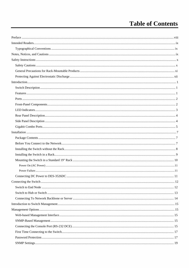
Table of Contents
Preface ..............................................................................................................................................................................................viii Intended Readers................................................................................................................................................................................. ix
Typographical Conventions .......................................................................................................................................................... ix Notes, Notices, and Cautions .............................................................................................................................................................. ix Safety Instructions ............................................................................................................................................................................... x
Safety Cautions .............................................................................................................................................................................. x General Precautions for Rack-Mountable Products ...................................................................................................................... xi Protecting Against Electrostatic Discharge.................................................................................................................................. xii
Introduction.......................................................................................................................................................................................... 1 Switch Description......................................................................................................................................................................... 1 Features .......................................................................................................................................................................................... 1 Ports ............................................................................................................................................................................................... 2 Front-Panel Components................................................................................................................................................................ 2 LED Indicators ............................................................................................................................................................................... 3 Rear Panel Description................................................................................................................................................................... 4 Side Panel Description ................................................................................................................................................................... 4 Gigabit Combo Ports...................................................................................................................................................................... 5
Installation ........................................................................................................................................................................................... 7 Package Contents ........................................................................................................................................................................... 7 Before You Connect to the Network.............................................................................................................................................. 7 Installing the Switch without the Rack........................................................................................................................................... 8 Installing the Switch in a Rack....................................................................................................................................................... 9 Mounting the Switch in a Standard 19" Rack .............................................................................................................................. 10
Power On (AC Power) ..................................................................................................................................................................................11 Power Failure ................................................................................................................................................................................................11
Connecting DC Power to DES-3526DC ...................................................................................................................................... 11 Connecting the Switch ....................................................................................................................................................................... 12
Switch to End Node ..................................................................................................................................................................... 12 Switch to Hub or Switch .............................................................................................................................................................. 13 Connecting To Network Backbone or Server .............................................................................................................................. 14
Introduction to Switch Management.................................................................................................................................................. 15 Management Options ......................................................................................................................................................................... 15
Web-based Management Interface............................................................................................................................................... 15 SNMP-Based Management .......................................................................................................................................................... 15 Connecting the Console Port (RS-232 DCE) ............................................................................................................................... 15 First Time Connecting to the Switch............................................................................................................................................ 17 Password Protection ..................................................................................................................................................................... 17 SNMP Settings............................................................................................................................................................................. 19

Traps .............................................................................................................................................................................................................19 MIBs .............................................................................................................................................................................................................19
IP Address Assignment ................................................................................................................................................................ 20 Connecting Devices to the Switch ............................................................................................................................................... 21
Web-based Switch Configuration ...................................................................................................................................................... 22 Introduction........................................................................................................................................................................................ 22
Login to Web Manager ................................................................................................................................................................ 22 Web-based User Interface ............................................................................................................................................................ 23
Areas of the User Interface ...........................................................................................................................................................................23 Web Pages.................................................................................................................................................................................... 24
Configuring the Switch ...................................................................................................................................................................... 25 Switch Information ............................................................................................................................................................................ 26 IP Address.......................................................................................................................................................................................... 26 Advanced Settings ............................................................................................................................................................................. 30 Port Configuration ............................................................................................................................................................................. 32 Port Description ................................................................................................................................................................................. 34 Port Mirroring .................................................................................................................................................................................... 35 Link Aggregation............................................................................................................................................................................... 36
Understanding Port Trunk Groups ................................................................................................................................................................36 LACP Port Setting ............................................................................................................................................................................. 39 MAC Notification .............................................................................................................................................................................. 40
MAC Notification Global Settings............................................................................................................................................... 40 MAC Notification Port Settings................................................................................................................................................... 41
IGMP ................................................................................................................................................................................................. 42 IGMP Snooping ........................................................................................................................................................................... 42 Static Router Ports Entry.............................................................................................................................................................. 44 Forbidden Router Ports Entry ...................................................................................................................................................... 45 IGMP Multicast VLAN................................................................................................................................................................ 46
Spanning Tree .................................................................................................................................................................................... 49 802.1s MSTP ................................................................................................................................................................................................49 802.1w Rapid Spanning Tree........................................................................................................................................................................49 Port Transition States ....................................................................................................................................................................................49 Edge Port.......................................................................................................................................................................................................50 P2P Port ........................................................................................................................................................................................................50 802.1d/802.1w/802.1s Compatibility ............................................................................................................................................................50
STP Bridge Global Settings ......................................................................................................................................................... 51 MST Configuration Table ............................................................................................................................................................ 54 MSTI Settings .............................................................................................................................................................................. 56 STP Instance Settings................................................................................................................................................................... 57 MSTP Port Information................................................................................................................................................................ 59
Loopback Detection........................................................................................................................................................................... 62 Forwarding Filtering .......................................................................................................................................................................... 63

Unicast Forwarding...................................................................................................................................................................... 63 Multicast Forwarding ................................................................................................................................................................... 64 Multicast Port Filtering Mode...................................................................................................................................................... 65
VLANs............................................................................................................................................................................................... 67 Understanding IEEE 802.1p Priority.............................................................................................................................................................67
VLAN Description....................................................................................................................................................................... 67 Notes about VLANs on the xStack® DES-3500 Series switches ..................................................................................................................67
IEEE 802.1Q VLANs................................................................................................................................................................... 67 802.1Q VLAN Tags......................................................................................................................................................................................69 Port VLAN ID...............................................................................................................................................................................................69 Tagging and Untagging.................................................................................................................................................................................70 Ingress Filtering ............................................................................................................................................................................................70 Default VLANs.............................................................................................................................................................................................70 Port-based VLANs........................................................................................................................................................................................71 VLAN Segmentation.....................................................................................................................................................................................71 Asymmetric VLANs .....................................................................................................................................................................................72 VLAN and Trunk Groups .............................................................................................................................................................................73
Static VLAN Entry....................................................................................................................................................................... 73 GVRP Setting............................................................................................................................................................................... 76 Traffic Control ............................................................................................................................................................................. 77 Port Security................................................................................................................................................................................. 81
QoS .................................................................................................................................................................................................... 82 Advantages of QoS .......................................................................................................................................................................................82 Understanding QoS.......................................................................................................................................................................................83
Port Bandwidth ............................................................................................................................................................................ 84 Scheduling.................................................................................................................................................................................... 85 802.1p Default Priority................................................................................................................................................................. 86 802.1p User Priority ..................................................................................................................................................................... 86 Traffic Segmentation.................................................................................................................................................................... 87
System Severity Alerts....................................................................................................................................................................... 88 System Log Server............................................................................................................................................................................. 88 SNTP Settings.................................................................................................................................................................................... 90
Time Setting................................................................................................................................................................................. 90 Time Zone and DST..................................................................................................................................................................... 91
ACL ................................................................................................................................................................................................... 93 Access Profile Table .................................................................................................................................................................... 93
ACL Flow Meter.............................................................................................................................................................................. 111 CPU Interface Filtering.................................................................................................................................................................... 112
CPU Interface Filtering Profile Table ........................................................................................................................................ 112 Time Range Settings ........................................................................................................................................................................ 123 IP-MAC Binding.............................................................................................................................................................................. 123
ACL Mode ................................................................................................................................................................................. 123

IP-MAC Binding Port ................................................................................................................................................................ 126 IP-MAC Binding Table.............................................................................................................................................................. 127 IP-MAC Binding Blocked.......................................................................................................................................................... 128 DHCP Snooping Entries ............................................................................................................................................................ 128 IP-MAC Binding Permit IP Pool ............................................................................................................................................... 129
Limited IP Multicast Range ............................................................................................................................................................. 130 Limited IP Multicast Range Profile Settings.............................................................................................................................. 130 Limited IP Multicast Range Status Setting ................................................................................................................................ 131 Limited IP Multicast Range Setting ........................................................................................................................................... 132
Layer 3 IP Networking..................................................................................................................................................................... 133 Static ARP Table........................................................................................................................................................................ 133
Gratuitous ARP Settings .................................................................................................................................................................. 134 DHCP/BOOTP Relay................................................................................................................................................................. 135
DHCP / BOOTP Relay Global Settings ......................................................................................................................................................135 The Implementation of DHCP Information Option 82 in the xStack® DES-3500 Series switches .............................................................137 DHCP/BOOTP Relay Interface Settings.....................................................................................................................................................138 DHCP Option 60 Settings ...........................................................................................................................................................................139 DHCP Option 61 Settings ...........................................................................................................................................................................140 DHCP Local Relay Settings........................................................................................................................................................................141
LLDP ............................................................................................................................................................................................... 142 LLDP Global Settings ................................................................................................................................................................ 142 Basic LLDP Port Settings .......................................................................................................................................................... 144 802.1 Extension LLDP Port Settings ......................................................................................................................................... 145 802.3 Extension LLDP Port Settings ......................................................................................................................................... 146 LLDP Management Address Settings ........................................................................................................................................ 147 LLDP Statistics .......................................................................................................................................................................... 148 LLDP Management Address Table............................................................................................................................................ 149 LLDP Local Port Table.............................................................................................................................................................. 149 LLDP Remote Port Information................................................................................................................................................. 152
Security Management ...................................................................................................................................................................... 153 Trusted Host..................................................................................................................................................................................... 153 User Accounts.................................................................................................................................................................................. 154 Port Access Entity (802.1X) ............................................................................................................................................................ 156
802.1x Port-Based and MAC-Based Access Control................................................................................................................. 156 Authentication Server .................................................................................................................................................................................157 Authenticator ..............................................................................................................................................................................................157 Client...........................................................................................................................................................................................................158
Authentication Process............................................................................................................................................................... 158 Port-Based Network Access Control.......................................................................................................................................... 159 MAC-Based Network Access Control ....................................................................................................................................... 160 Configure Authenticator............................................................................................................................................................. 161 PAE System Control .................................................................................................................................................................. 164

Port Capability ............................................................................................................................................................................................164 Initializing Ports for Port Based 802.1x ......................................................................................................................................................165 Initializing Ports for MAC Based 802.1x....................................................................................................................................................166 Reauthenticate Port(s) for Port Based 802.1x .............................................................................................................................................166 Reauthenticate Port(s) for MAC Based 802.1x...........................................................................................................................................167
RADIUS Server ......................................................................................................................................................................... 167 Guest VLANs............................................................................................................................................................................. 168
Limitations Using the Guest VLAN............................................................................................................................................................168 Guest VLAN Configuration....................................................................................................................................................... 169
Access Authentication Control ........................................................................................................................................................ 169 Policy & Parameters................................................................................................................................................................... 171 Application's Authentication Settings ........................................................................................................................................ 171 Authentication Server Group ..................................................................................................................................................... 172 Authentication Server Hosts....................................................................................................................................................... 173 Login Method Lists .................................................................................................................................................................... 175 Enable Method Lists .................................................................................................................................................................. 176 Local Enable Password .............................................................................................................................................................. 178 Enable Admin ............................................................................................................................................................................ 178
Secure Socket Layer (SSL) .............................................................................................................................................................. 180 Download Certificate ................................................................................................................................................................. 180 Configuration ............................................................................................................................................................................. 181
Secure Shell (SSH) .......................................................................................................................................................................... 182 SSH Configuration..................................................................................................................................................................... 182 SSH Algorithm........................................................................................................................................................................... 183 SSH User Authentication ........................................................................................................................................................... 185
SNMP Manager ............................................................................................................................................................................... 187 SNMP Settings........................................................................................................................................................................... 187
Traps ...........................................................................................................................................................................................................187 MIBs ...........................................................................................................................................................................................................187
SNMP User Table ...................................................................................................................................................................... 188 SNMP View Table ..................................................................................................................................................................... 190 SNMP Group Table.................................................................................................................................................................... 191 SNMP Community Table........................................................................................................................................................... 192 SNMP Host Table ...................................................................................................................................................................... 193 SNMP Engine ID ....................................................................................................................................................................... 194 SNMP Trap ................................................................................................................................................................................ 194
Safeguard Engine............................................................................................................................................................................. 196 Filter................................................................................................................................................................................................. 198
DHCP Server Screening Setting ................................................................................................................................................ 198 DHCP Client Filtering Setting ................................................................................................................................................... 199 NetBIOS Filtering Setting.......................................................................................................................................................... 200 CPU Filtering Settings ............................................................................................................................................................... 202

ARP Spoofing Prevention .......................................................................................................................................................... 202 Monitoring ....................................................................................................................................................................................... 204 Port Utilization................................................................................................................................................................................. 204 CPU Utilization................................................................................................................................................................................ 205 Memory Usage................................................................................................................................................................................. 205 Packets ............................................................................................................................................................................................. 207
Received (RX)............................................................................................................................................................................ 207 UMB Cast (RX) ......................................................................................................................................................................... 208 Transmitted (TX) ....................................................................................................................................................................... 211
Errors ............................................................................................................................................................................................... 213 Received (RX)............................................................................................................................................................................ 213 Transmitted (TX) ....................................................................................................................................................................... 215
Size - Packet Size............................................................................................................................................................................. 216 MAC Address .................................................................................................................................................................................. 219 Switch History Log.......................................................................................................................................................................... 220 IGMP Snooping Group.................................................................................................................................................................... 221 IGMP Snooping Forwarding............................................................................................................................................................ 222 VLAN Status.................................................................................................................................................................................... 223 Router Port....................................................................................................................................................................................... 223 Port Access Control ......................................................................................................................................................................... 223
Authenticator State..................................................................................................................................................................... 224 Layer 3 Features............................................................................................................................................................................... 226
Browse ARP Table..................................................................................................................................................................... 226 Safeguard Engine Status .................................................................................................................................................................. 227 Cable Diagnostic.............................................................................................................................................................................. 228 Maintenance..................................................................................................................................................................................... 229 TFTP Services.................................................................................................................................................................................. 229
Download Firmware................................................................................................................................................................... 229 Download Configuration File..................................................................................................................................................... 230 Upload Configuration................................................................................................................................................................. 230 Upload Log ................................................................................................................................................................................ 231
Multiple Image Services .................................................................................................................................................................. 231 Firmware Information ................................................................................................................................................................ 231 Config Firmware Image ............................................................................................................................................................. 232
Ping Test .......................................................................................................................................................................................... 233 Save Changes................................................................................................................................................................................... 233 Reset ................................................................................................................................................................................................ 234 Reset System.................................................................................................................................................................................... 234 Reset Config .................................................................................................................................................................................... 235 Reboot Device.................................................................................................................................................................................. 235 Logout.............................................................................................................................................................................................. 235

D-Link Single IP Management ........................................................................................................................................................ 236 Single IP Management (SIM) Overview.......................................................................................................................................... 236
The Upgrade to v1.6....................................................................................................................................................................................237 SIM Using the Web Interface .......................................................................................................................................................... 238 Topology.......................................................................................................................................................................................... 239 Tool Tips.......................................................................................................................................................................................... 241
Right-Click................................................................................................................................................................................. 242 Group Icon ..................................................................................................................................................................................................242 Commander Switch Icon.............................................................................................................................................................................243 Member Switch Icon...................................................................................................................................................................................244 Candidate Switch Icon ................................................................................................................................................................................245
Menu Bar ................................................................................................................................................................................... 247 Group ..........................................................................................................................................................................................................247 Device .........................................................................................................................................................................................................247 View............................................................................................................................................................................................................247
Firmware Upgrade ..................................................................................................................................................................... 248 Configuration File Backup/Restore............................................................................................................................................ 248 Upload Log File ......................................................................................................................................................................... 248
Technical Specifications .................................................................................................................................................................. 250 Cables and Connectors..................................................................................................................................................................... 252 System Log Entries .......................................................................................................................................................................... 253 Cable Lengths .................................................................................................................................................................................. 264 Mitigating ARP Spoofing Attacks Using Packet Content ACL....................................................................................................... 265 Glossary ........................................................................................................................................................................................... 273 Warrenties/Registration ................................................................................................................................................................... 276 Tech Support.................................................................................................................................................................................... 284

xStack® DES-3500 Series Layer 2 Stackable Fast Ethernet Managed Switch User Manual
viii
Preface The DES-3500 Series Manual is divided into sections that describe the system installation and operating instructions with examples.
Section 1, Introduction - Describes the Switch and its features.
Section 2, Installation- Helps you get started with the basic installation of the Switch and also describes the front panel, rear panel, side panels, and LED indicators of the Switch. Included in this section is a description of how to hook up the DC power supply for the DES-3500 Series switches.
Section 3, Connecting the Switch - Tells how you can connect the Switch to your Ethernet/Fast Ethernet network.
Section 4, Introduction to Switch Management - Introduces basic Switch management features, including password protection, SNMP settings, IP address assignment and connecting devices to the Switch.
Section 5, Introduction to Web-based Switch Management - Talks about connecting to and using the Web-based switch management feature on the Switch.
Section 6, Configuring the Switch - A detailed discussion about configuring some of the basic functions of the Switch, including accessing the Switch information, using the Switch's utilities and setting up network configurations, such as Quality of Service, The Access Profile Table, port mirroring and configuring the Spanning Tree.
Section 7, Security Management - A discussion of the security features of the Switch, including Security IP, User Accounts, Access Authentication Control, and SNMP.
Section 8, Monitoring - Features graphs and screens used in monitoring features and packets on the Switch.
Section 9, Maintenance - Features information on Switch utility functions, including TFTP Services, Switch History, Ping Test Save Changes and Rebooting Services.
Section 10, Single IP Management - Discussion on the Single IP Management function of the Switch, including functions and features of the Java based user interface and the utilities of the SIM function.
Appendix A, Technical Specifications - The technical specifications of the DES-3500 Series switches.
Appendix B, Cables and Connectors - Describes the RJ-45 receptacle/connector, straight through and crossover cables and standard pin assignments.
Appendix C, Cable Lengths - Information on cable types and maximum distances.
Glossary - Lists definitions for terms and acronyms used in this document.

xStack® DES-3500 Series Layer 2 Stackable Fast Ethernet Managed Switch User Manual
ix
Intended Readers The DES-3500 Manual contains information for setup and management of the Switch. This manual is intended for network managers familiar with network management concepts and terminology.
Typographical Conventions Convention Description
[ ] In a command line, square brackets indicate an optional entry. For example: [copy filename] means that optionally you can type copy followed by the name of the file. Do not type the brackets.
Bold font Indicates a button, a toolbar icon, menu, or menu item. For example: Open the File menu and choose Cancel. Used for emphasis. May also indicate system messages or prompts appearing on your screen. For example: You have mail. Bold font is also used to represent filenames, program names and commands. For example: use the copy command.
Boldface Typewriter Font
Indicates commands and responses to prompts that must be typed exactly as printed in the manual.
Initial capital letter Indicates a window name. Names of keys on the keyboard have initial capitals. For example: Click Enter.
Italics Indicates a window name or a field. Also can indicate a variables or parameter that is replaced with an appropriate word or string. For example: type filename means that you should type the actual filename instead of the word shown in italic.
Menu Name > Menu Option
Menu Name > Menu Option Indicates the menu structure. Device > Port > Port Properties means the Port Properties menu option under the Port menu option that is located under the Device menu.
Notes, Notices, and Cautions
A NOTE indicates important information that helps you make better use of your device.
A NOTICE indicates either potential damage to hardware or loss of data and tells you how to avoid the problem.
A CAUTION indicates a potential for property damage, personal injury, or death.
xStack® DES-3500 Series Layer 2 Stackable Fast Ethernet Managed Switch User Manual
x
Safety Instructions Use the following safety guidelines to ensure your own personal safety and to help protect your system from potential damage. Throughout this document, the caution icon ( ) is used to indicate cautions and precautions that you need to review and follow.
Safety Cautions
To reduce the risk of bodily injury, electrical shock, fire, and damage to the equipment, observe the following precautions.
• Observe and follow service markings.
• Do not service any product except as explained in your system documentation.
• Opening or removing covers that are marked with the triangular symbol with a lightning bolt may expose you to electrical shock.
• Only a trained service technician should service components inside these compartments.
• If any of the following conditions occur, unplug the product from the electrical outlet and replace the part or contact your trained service provider:
• The power cable, extension cable, or plug is damaged.
• An object has fallen into the product.
• The product has been exposed to water.
• The product has been dropped or damaged.
• The product does not operate correctly when you follow the operating instructions.
• Keep your system away from radiators and heat sources. Also, do not block cooling vents.
• Do not spill food or liquids on your system components, and never operate the product in a wet environment. If the system gets wet, see the appropriate section in your troubleshooting guide or contact your trained service provider.
• Do not push any objects into the openings of your system. Doing so can cause fire or electric shock by shorting out interior components.
• Use the product only with approved equipment.
• Allow the product to cool before removing covers or touching internal components.
• Operate the product only from the type of external power source indicated on the electrical ratings label. If you are not sure of the type of power source required, consult your service provider or local power company.
• To help avoid damaging your system, be sure the voltage on the power supply is set to match the power available at your location:
• 115 volts (V)/60 hertz (Hz) in most of North and South America and some Far Eastern countries such as South Korea and Taiwan
• 100 V/50 Hz in eastern Japan and 100 V/60 Hz in western Japan
• 230 V/50 Hz in most of Europe, the Middle East, and the Far East
• –48 VDC for DC power supply unit on DES-3526DC only
• Also, be sure that attached devices are electrically rated to operate with the power available in your location.
• Use only approved power cable(s). If you have not been provided with a power cable for your system or for any AC-powered option intended for your system, purchase a power cable that is approved for use in your country. The power cable must be rated for the product and for the voltage and current marked on the product's electrical ratings label. The voltage and current rating of the cable should be greater than the ratings marked on the product.
• To help prevent electric shock, plug the system and peripheral power cables into properly grounded electrical outlets. These cables are equipped with three-prong plugs to help ensure proper grounding. Do not use adapter plugs or remove the grounding prong from a cable. If you must use an extension cable, use a 3-wire cable with properly grounded plugs.
xStack® DES-3500 Series Layer 2 Stackable Fast Ethernet Managed Switch User Manual
xi
• Observe extension cable and power strip ratings. Make sure that the total ampere rating of all products plugged into the extension cable or power strip does not exceed 80 percent of the ampere ratings limit for the extension cable or power strip.
• To help protect your system from sudden, transient increases and decreases in electrical power, use a surge suppressor, line conditioner, or uninterruptible power supply (UPS).
• Position system cables and power cables carefully; route cables so that they cannot be stepped on or tripped over. Be sure that nothing rests on any cables.
• Do not modify power cables or plugs. Consult a licensed electrician or your power company for site modifications. Always follow your local/national wiring rules.
• When connecting or disconnecting power to hot-pluggable power supplies, if offered with your system, observe the following guidelines:
• Install the power supply before connecting the power cable to the power supply.
• Unplug the power cable before removing the power supply.
• If the system has multiple sources of power, disconnect power from the system by unplugging all power cables from the power supplies.
• Move products with care; ensure that all casters and/or stabilizers are firmly connected to the system. Avoid sudden stops and uneven surfaces.
General Precautions for Rack-Mountable Products
Observe the following precautions for rack stability and safety. Also, refer to the rack installation documentation accompanying the system and the rack for specific caution statements and procedures.
• Systems are considered to be components in a rack. Thus, "component" refers to any system as well as to various peripherals or supporting hardware.
• Before working on the rack, make sure that the stabilizers are secured to the rack, extended to the floor, and that the full weight of the rack rests on the floor. Install front and side stabilizers on a single rack or front stabilizers for joined multiple racks before working on the rack.
• Always load the rack from the bottom up, and load the heaviest item in the rack first.
• Make sure that the rack is level and stable before extending a component from the rack.
• Use caution when pressing the component rail release latches and sliding a component into or out of a rack; the slide rails can pinch your fingers.
• After a component is inserted into the rack, carefully extend the rail into a locking position, and then slide the component into the rack.
• Do not overload the AC supply branch circuit that provides power to the rack. The total rack load should not exceed 80 percent of the branch circuit rating.
• Ensure that proper airflow is provided to components in the rack.
• Do not step on or stand on any component when servicing other components in a rack.
NOTE: A qualified electrician must perform all connections to DC power and to safety grounds. All electrical wiring must comply with applicable local, regional or national codes and practices.
CAUTION: Never defeat the ground conductor or operate the equipment in the absence of a suitably installed ground conductor. Contact the appropriate electrical inspection authority or an electrician if you are uncertain that suitable grounding is available.
CAUTION: The system chassis must be positively grounded to the rack cabinet frame. Do not attempt to connect power to the system until grounding cables are connected. A qualified electrical inspector must inspect completed power and safety ground wiring. An energy hazard will exist if the safety ground cable is omitted or disconnected.

xStack® DES-3500 Series Layer 2 Stackable Fast Ethernet Managed Switch User Manual
xii
Protecting Against Electrostatic Discharge Static electricity can harm delicate components inside your system. To prevent static damage, discharge static electricity from your body before you touch any of the electronic components, such as the microprocessor. You can do so by periodically touching an unpainted metal surface on the chassis.
You can also take the following steps to prevent damage from electrostatic discharge (ESD): 1. When unpacking a static-sensitive component from its shipping carton, do not remove the component from the antistatic
packing material until you are ready to install the component in your system. Just before unwrapping the antistatic packaging, be sure to discharge static electricity from your body.
2. When transporting a sensitive component, first place it in an antistatic container or packaging. 3. Handle all sensitive components in a static-safe area. If possible, use antistatic floor pads, workbench pads and an
antistatic grounding strap.

xStack® DES-3500 Series Layer 2 Stackable Fast Ethernet Managed Switch User Manual
1
Section 1 Introduction
Switch Description Features Ports Front-Panel Components Side Panel Description Rear Panel Description Gigabit Combo Ports
The DES-3500 layer 2 Fast Ethernet switches are members of the D-Link xStack® family. Ranging from 10/100Mbps edge switches to core gigabit switches, the xStack® switch family has been future-proof designed to provide a stacking architecture with fault tolerance, flexibility, port density, robust security and maximum throughput with a user-friendly management interface for the networking professional.
The following manual describes the installation, maintenance and configurations concerning members of the xStack® DES-3500 switch series. These three switches, the DES-3526, DES-3526DC, and the DES-3550 are all very similar in configurations and basic hardware and consequentially, most of the information in this manual will be universal to the whole xStack® DES-3500 switch series. Corresponding screen pictures of the web manager may be taken from any one of these switches but the configuration will be identical, except for varying port counts.
Switch Description The DES-3500 Series switches are equipped with unshielded twisted-pair (UTP) cable ports providing dedicated 10 or 100 Mbps bandwidth. The Switch has 24 UTP ports (48 UTP ports for the DES-3550) and Auto MDI-X/MDI-II convertible ports that can be used for unlinking to another switch. These ports can be used for connecting PCs, printers, servers, hubs, routers, switches and other networking devices. The dual speed ports use standard twisted-pair cabling and are ideal for segmenting networks into small, connected sub networks for superior performance. Each 10/100 port can support up to 200 Mbps of throughput in full-duplex mode. In addition, the Switch has 2 Mini-GBIC combo ports. These two-gigabit combo ports are ideal for connecting to a server or network backbone. This stand-alone Switch enables the network to use some of the most demanding multimedia and imaging applications concurrently with other user applications without creating bottlenecks. The built-in console interface can be used to configure the Switch's settings for priority queuing, VLANs, and port trunk groups, port monitoring, and port speed.
NOTE: For the remainder of this manual, all hardware versions of the DES-3500 Series switches will be referred to as simply the Switch or the DES-3500 except where the differences are relevant.
Features
• IEEE 802.3 10BASE-T compliant
• IEEE 802.3u 100BASE-TX compliant
• IEEE 802.1p Priority Queues
• IEEE 802.3x flow control in full duplex mode
• IEEE 802.3ad Link Aggregation Control Protocol support.
• IEEE 802.1x Port-based and MAC-based Access Control
• IEEE 802.1Q VLAN
• IEEE 802.1D Spanning Tree, IEEE 802.1W Rapid Spanning Tree and IEEE 802.1s Multiple Spanning Tree support
• Access Control List (ACL) support
• Single IP Management support
• Access Authentication Control utilizing TACACS, XTACACS and TACACS+
• Dual Image Firmware
• Simple Network Time Protocol support

xStack® DES-3500 Series Layer 2 Stackable Fast Ethernet Managed Switch User Manual
2
• MAC Notification support
• Asymmetric VLAN support
• System and Port Utilization support
• System Log Support
• Address table: Supports up to 8K MAC addresses per device
• Supports 16M Bytes buffer memory per device
• Supports Port-based VLAN Groups
• Port Trunking with flexible load distribution and fail-over function
• IGMP Snooping support
• SNMP support
• Secure Sockets Layer (SSL) and Secure Shell (SSH) support
• Port Mirroring support
• MIB support for:
• RFC1213 MIB II
• RFC1493 Bridge
• RFC1757 RMON
• RFC1643 Ether-like MIB
• RFC2233 Interface MIB
• Private MIB
• RFC2674 for 802.1p
• IEEE 802.1x MIB
• RS-232 DCE console port for Switch management
• Provides parallel LED display for port status such as link/act, speed, etc.
• High performance switching engine performs forwarding and filtering at full wire speed, maximum 14, 881 packets/sec on each 10Mbps Ethernet port, and maximum 148,810 packet/sec on 100Mbps Fast Ethernet port.
• Full- and half-duplex for both 10Mbps and 100Mbps connections. Full duplex allows the switch port to simultaneously transmit and receive data. It only works with connections to full-duplex-capable end stations and switches. Connections to a hub must take place at half-duplex
• Support broadcast storm filtering
• Non-blocking store and forward switching scheme capability to support rate adaptation and protocol conversion
• Supports by-port Egress/Ingress rate control.
• Supports IP-MAC Port Binding.
• Efficient self-learning and address recognition mechanism enables forwarding rate at wire speed
• Safeguard Engine Support
Ports • Twenty-four (48 for the DES-3550) high-performance (MDI-X/MDI-II) ports for connecting to end stations, servers,
hubs and other networking devices.
• All UTP ports can auto-negotiate between 10Mbps and 100Mbps, half-duplex and full duplex, and feature flow control.
• Two 1000BASE-T Mini-GBIC combo ports for connecting to another switch, server, or network backbone.
• RS-232 DCE Diagnostic port (console port) for setting up and managing the Switch via a connection to a console terminal or PC using a terminal emulation program.
NOTE: For customers interested in D-View, D-Link Corporation's proprietary SNMP management software, go to the D-Link Website (www.dlink.com) and download the software and manual.

xStack® DES-3500 Series Layer 2 Stackable Fast Ethernet Managed Switch User Manual
2
Front-Panel Components The front panel of the Switch consists of LED indicators for power and for each 10/100 Mbps twisted-pair ports, and two 1000BASE-T Mini-GBIC ports.
Figure 1- 1. Front Panel View of the DES-3526 switch
Figure 1- 2. Front Panel View of the DES-3550 switch
The DES-3526DC does not support a redundant power supply and therefore the RPS indicator does not appear on the front panel.
Figure 1- 3. Front Panel View of DES-3526DC
Comprehensive LED indicators display the status of the Switch and the network.

xStack® DES-3500 Series Layer 2 Stackable Fast Ethernet Managed Switch User Manual
3
LED Indicators The Switch supports LED indicators for Power, Console, RPS (DES-3526/3550) and Port LEDs. The following shows the LED indicators for the DES-3500 Series switches along with an explanation of each indicator. LEDs and there corresponding meanings are displayed below.
Figure 1- 4. LED Indicators on DES-3526 Series switches
Figure 1- 5. Indicators on DES-3550 Series switch
LED Description
Power This LED will light green after the Switch is powered on to indicate the ready state of the device. The indicator is dark when the Switch is powered off.
Console This LED should blink during the Power-On Self Test (POST). When the POST is finished, the LED goes dark. This indicator is lit sold green when the Switch is being logged into via out-of-band/local console management through the RS-232 console port in the back of the Switch using a straight-through serial cable.
RPS (DES-3526DC not supported)
This LED will be lit when the redundant power supply is present and in use. Otherwise it will remain dark.
Port LEDs One row of LEDs for each port is located above the ports on the front panel. The first LED is for the top port and the second one is for the bottom ports. These port LEDs will light two different colors for 10M and 100M.
• Amber - For speeds of 10 Mbps. A solid light denotes activity on the port while a blinking light indicates a valid link.
• Green - For speeds of 100 Mbps. A solid light denotes activity on the port while a blinking light indicates a valid link.
100M/10M These LEDs will light steady green to indicate that the port is transferring data at 100Mbps.
Gigabit Ports The Switch's two Mini GBIC ports have their own corresponding LEDs: Speed - This LED will light solid green when the port is transferring at a rate of 1000Mbps. When dark, the port is transferring at 10/100Mbps. Link/Act - This LED will light solid green when there is a valid link. A blinking LED indicates current activity on the port. A dark LED indicates no activity on the port.

xStack® DES-3500 Series Layer 2 Stackable Fast Ethernet Managed Switch User Manual
4
Rear Panel Description The rear panel of the Switch contains an AC power connector.
Figure 1- 6. Rear panel view of the DES-3526
Figure 1- 7. Rear panel view of the DES-3550
The AC power connector is a standard three-pronged connector that supports the power cord. Plug-in the female connector of the provided power cord into this socket, and the male side of the cord into a power outlet. The Switch automatically adjusts its power setting to any supply voltage in the range from 100 ~ 240 VAC at 50 ~ 60 Hz. The rear panel also includes an outlet for an optional external power supply. When power fails, the optional external RPS will take over all the power immediately and automatically.
Figure 1- 8. Rear panel view of DES-3526DC
The rear panel of the DC power version of the Switch includes an opening designed to accommodate the DC power wiring assembly. See the installation instructions in this Section for details.
Side Panel Description The right-hand side panel of the Switch contains a system fan, while the left hand panel includes a system fan and a heat vent. The system fans are used to dissipate heat. The sides of the system also provide heat vents to serve the same purpose. Do not block these openings, and leave at least 6 inches of space at the rear and sides of the Switch for proper ventilation. Be reminded that without proper heat dissipation and air circulation, system components might overheat, which could lead to system failure.
Figure 1- 9. Side panels of the DES-3526/DES-3526DC

xStack® DES-3500 Series Layer 2 Stackable Fast Ethernet Managed Switch User Manual
5
Figure 1- 10. Side panels of the DES-3550
Gigabit Combo Ports In addition to the 24 (or 48) 10/100 Mbps ports, the Switch features two Gigabit Ethernet Combo ports. These two ports are 1000BASE-T copper ports (provided) and Mini-GBIC ports (optional). See the diagram below to view the two Mini-GBIC port modules being plugged into the Switch. Please note that although these two front panel modules can be used simultaneously, the ports must be different. The GBIC port will always have the highest priority.
Figure 1- 11. Inserting the Mini-GBIC modules into the DES-3526
Figure 1- 12. Inserting the Mini-GBIC modules into the DES-3550

xStack® DES-3500 Series Layer 2 Stackable Fast Ethernet Managed Switch User Manual
6
Figure 1- 13. Installing the Mini-GBIC Module
xStack® DES-3500 Series Layer 2 Stackable Fast Ethernet Managed Switch User Manual
7
SECTION 2 Installation
Package Contents
Before You Connect to the Network
Installing the Switch without the Rack
Rack Installation
Power On
Package Contents Open the shipping carton of the Switch and carefully unpack its contents. The carton should contain the following items:
• One xStack® DES-3500 Series switch
• One AC power cord
• One CD Kit for User’s Guide/CLI/D-View module
• Quick Installation Guide
• Registration card
• Mounting kit (two brackets and screws)
• Four rubber feet with adhesive backing
• RS-232 console cable
If any item is found missing or damaged, please contact your local D-Link Reseller for replacement.
Before You Connect to the Network The site where you install the Switch may greatly affect its performance. Please follow these guidelines for setting up the Switch.
• Install the Switch on a sturdy, level surface that can support at least 6.6 lb. (3 kg) of weight. Do not place heavy objects on the Switch.
• The power outlet should be within 1.82 meters (6 feet) of the Switch.
• Visually inspect the power cord and see that it is fully secured to the AC power port.
• Make sure that there is proper heat dissipation from and adequate ventilation around the Switch. Leave at least 10 cm (4 inches) of space at the front and rear of the Switch for ventilation.
• Install the Switch in a fairly cool and dry place for the acceptable temperature and humidity operating ranges.
• Install the Switch in a site free from strong electromagnetic field generators (such as motors), vibration, dust, and direct exposure to sunlight.
• When installing the Switch on a level surface, attach the rubber feet to the bottom of the device. The rubber feet cushion the Switch, protect the casing from scratches and prevent it from scratching other surfaces.

xStack® DES-3500 Series Layer 2 Stackable Fast Ethernet Managed Switch User Manual
8
Installing the Switch without the Rack When installing the Switch on a desktop or shelf, the rubber feet included with the Switch should first be attached. Attach these cushioning feet on the bottom at each corner of the device. Allow enough ventilation space between the Switch and any other objects in the vicinity.
Figure 2- 1. Preparing the DES-3526 for installation on a desktop or shelf
Figure 2- 2. Preparing the DES-3550 for installation on a desktop or shelf

xStack® DES-3500 Series Layer 2 Stackable Fast Ethernet Managed Switch User Manual
9
Installing the Switch in a Rack The Switch can be mounted in a standard 19" rack. Use the following diagrams to guide you.
Figure 2- 3. Fasten mounting brackets to the DES-3526
Figure 2- 4. Fasten mounting brackets to the DES-3550
Fasten the mounting brackets to the Switch using the screws provided. With the brackets attached securely, you can mount the Switch in a standard rack as shown in Figure 2-3 below.

xStack® DES-3500 Series Layer 2 Stackable Fast Ethernet Managed Switch User Manual
10
Mounting the Switch in a Standard 19" Rack
CAUTION: Installing systems in a rack without the front and side stabilizers installed could cause the rack to tip over, potentially resulting in bodily injury under certain circumstances. Therefore, always install the stabilizers before installing components in the rack. After installing components in a rack, do not pull more than one component out of the rack on its slide assemblies at one time. The weight of more than one extended component could cause the rack to tip over and may result in injury.
Figure 2- 5. Installing the DES-3526 in a rack
Figure 2- 6. Installing the DES-3550 in a rack

xStack® DES-3500 Series Layer 2 Stackable Fast Ethernet Managed Switch User Manual
11
Power On (AC Power) Plug one end of the AC power cord into the power connector of the Switch and the other end into the local power source outlet. After the Switch is powered on, the LED indicators will momentarily blink. This blinking of the LED indicators represents a reset of the system.
Power Failure As a precaution for AC power supply units, in the event of a power failure, unplug the Switch. When power has resumed, plug the Switch back in.
Connecting DC Power to DES-3526DC Follow the instructions below to connect the DC power supply of the DES-3526DC to a DC power source.
Figure 2- 7. Power connections attached to contacts on assembly 1. Firmly attach the DC power to the negative and positive contacts on the wiring assembly.
• The negative pole (-) connects to the -48V contact. • The positive pole (+) connects to the -48V Return contact. • If available, the earth ground may be connected to center contact post.
2. Tighten the contact screws so the connection is secure.

xStack® DES-3500 Series Layer 2 Stackable Fast Ethernet Managed Switch User Manual
12
Section 3 Connecting the Switch
Switch to End Node
Switch to Hub or Switch
Connecting To Network Backbone or Server
NOTE: All 24 (48 for the DES-3550) high-performance NWay Ethernet ports can support both MDI-II and MDI-X connections.
Switch to End Node End nodes include PCs outfitted with a 10, 100 or 1000 Mbps RJ-45 Ethernet/Fast Ethernet Network Interface Card (NIC) and most routers. An end node can be connected to the Switch via a twisted-pair Category 3, 4, or 5 UTP/STP cable. The end node should be connected to any of the ports of the Switch.
Figure 3- 1. DES-3526 connected to an end node
Figure 3- 2 DES-3550 connected to an end node
The Link/Act LEDs for each UTP port will light green or amber when the link is valid. A blinking LED indicates packet activity on that port.
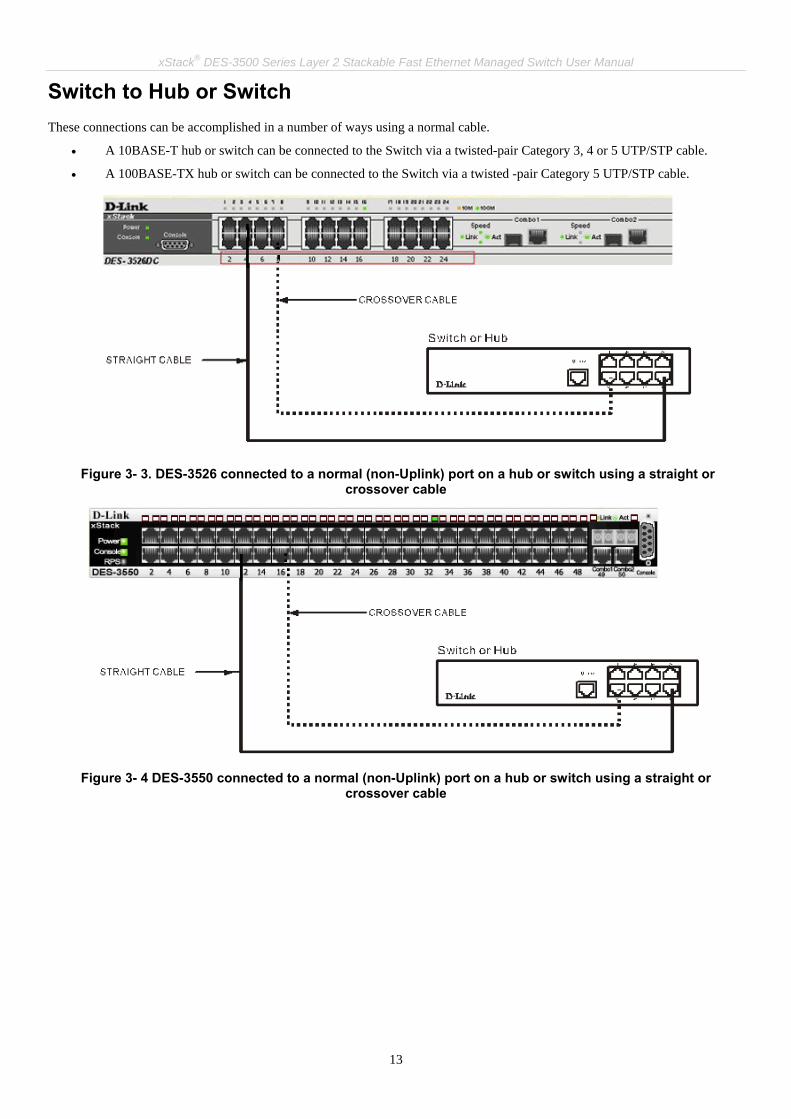
xStack® DES-3500 Series Layer 2 Stackable Fast Ethernet Managed Switch User Manual
13
Switch to Hub or Switch These connections can be accomplished in a number of ways using a normal cable.
• A 10BASE-T hub or switch can be connected to the Switch via a twisted-pair Category 3, 4 or 5 UTP/STP cable.
• A 100BASE-TX hub or switch can be connected to the Switch via a twisted -pair Category 5 UTP/STP cable.
Figure 3- 3. DES-3526 connected to a normal (non-Uplink) port on a hub or switch using a straight or
crossover cable
Figure 3- 4 DES-3550 connected to a normal (non-Uplink) port on a hub or switch using a straight or
crossover cable

xStack® DES-3500 Series Layer 2 Stackable Fast Ethernet Managed Switch User Manual
14
Connecting To Network Backbone or Server The two Mini-GBIC combo ports are ideal for unlinking to a network backbone or server. The copper ports operate at a speed of 1000, 100 or 10Mbps in full or half duplex mode. The fiber optic ports can operate at 1000Mbps in full duplex mode. Connections to the Gigabit Ethernet ports are made using fiber optic cable or Category 5 copper cable, depending on the type of port. A valid connection is indicated when the Link LED is lit.
Figure 3- 5. Connecting the DES-3500 Series switch to a Server
xStack® DES-3500 Series Layer 2 Stackable Fast Ethernet Managed Switch User Manual
15
Section 4
Introduction to Switch Management Management Options
Web-based Management Interface
SNMP-Based Management
Managing User Accounts
Command Line Console Interface through the Serial Port
Connecting the Console Port (RS-232 DCE)
First Time Connecting to the Switch
Password Protection
SNMP Settings
IP Address Assignment
Connecting Devices to the Switch
Management Options This system may be managed out-of-band through the console port on the front panel or in-band using Telnet. The user may also choose the web-based management, accessible through a web browser.
Web-based Management Interface After you have successfully installed the Switch, you can configure the Switch, monitor the LED panel, and display statistics graphically using a web browser, such as Netscape Navigator (version 6.2 and higher) or Microsoft® Internet Explorer (version 5.0).
SNMP-Based Management You can manage the Switch with an SNMP-compatible console program. The Switch supports SNMP version 1.0, version 2.0 and version 3.0. The SNMP agent decodes the incoming SNMP messages and responds to requests with MIB objects stored in the database. The SNMP agent updates the MIB objects to generate statistics and counters.
Connecting the Console Port (RS-232 DCE) The Switch provides an RS-232 serial port that enables a connection to a computer or terminal for monitoring and configuring the Switch. This port is a female DB-9 connector, implemented as a data terminal equipment (DTE) connection. To use the console port, you need the following equipment:
• A terminal or a computer with both a serial port and the ability to emulate a terminal.
• A null modem or crossover RS-232 cable with a female DB-9 connector for the console port on the Switch.

xStack® DES-3500 Series Layer 2 Stackable Fast Ethernet Managed Switch User Manual
16
To connect a terminal to the console port: 1. Connect the female connector of the RS-232 cable directly to the console port on the Switch, and tighten the captive
retaining screws. 2. Connect the other end of the cable to a terminal or to the serial connector of a computer running terminal emulation
software. Set the terminal emulation software as follows: 3. Select the appropriate serial port (COM port 1 or COM port 2). 4. Set the data rate to 9600 baud. 5. Set the data format to 8 data bits, 1 stop bit, and no parity. 6. Set flow control to none. 7. Under Properties, select VT100 for Emulation mode. 8. Select Terminal keys for Function, Arrow, and Ctrl keys. Ensure that you select Terminal keys (not Windows keys).
9. After you have correctly set up the terminal, plug the power cable into the power receptacle on the back of the Switch. The boot sequence appears in the terminal.
10. After the boot sequence completes, the console login screen displays. 11. If you have not logged into the command line interface (CLI) program, press the Enter key at the User name and
password prompts. There is no default user name and password for the Switch. The administrator must first create user names and passwords. If you have previously set up user accounts, log in and continue to configure the Switch.
12. Enter the commands to complete your desired tasks. Many commands require administrator-level access privileges. Read the next section for more information on setting up user accounts. See the DES-3500 Series switches Command Line Interface Reference Manual on the documentation CD for a list of all commands and additional information on using the CLI.
13. When you have completed your tasks, exit the session with the logout command or close the emulator program.
Make sure the terminal or PC you are using to make this connection is configured to match these settings. If you are having problems making this connection on a PC, make sure the emulation is set to VT-100. You will be able to set the emulation by clicking on the File menu in you HyperTerminal window, clicking on Properties in the drop-down menu, and then clicking the Settings tab. This is where you will find the Emulation options. If you still do not see anything, try rebooting the Switch by disconnecting its power supply. Once connected to the console, the screen below will appear on your console screen. This is where the user will enter commands to perform all the available management functions. The Switch will prompt the user to enter a user name and a password. Upon the initial connection, there is no user name or password and therefore just press enter twice to access the command line interface.
Figure 4- 1. Initial screen after first connection
NOTE: When you use HyperTerminal with the Microsoft® Windows® 2000 operating sys-tem, ensure that you have Windows 2000 Service Pack 2 or later installed. Windows 2000 Service Pack 2 allows you to use arrow keys in HyperTerminal's VT100 emulation. See www.microsoft.com for information on Windows 2000 service packs.

xStack® DES-3500 Series Layer 2 Stackable Fast Ethernet Managed Switch User Manual
17
First Time Connecting to the Switch The Switch supports user-based security that can allow you to prevent unauthorized users from accessing the Switch or changing its settings. This section tells how to log onto the Switch.
NOTE: The passwords used to access the Switch are case-sensitive; therefore, "S" is not the same as "s."
When you first connect to the Switch, you will be presented with the first login screen.
NOTE: Press Ctrl+R to refresh the screen. This command can be used at any time to force the console program in the Switch to refresh the console screen.
Press Enter in both the Username and Password fields. You will be given access to the command prompt DES-3500 Series switches:4# shown below: There is no initial username or password. Leave the Username and Password fields blank.
Figure 4- 2. Command Prompt
NOTE: The first user automatically gets Administrator level privileges. It is recommended to create at least one Admin-level user account for the Switch.
Password Protection The DES-3500 Series switches do not have a default user name and password. One of the first tasks when settings up the Switch is to create user accounts. If you log in using a predefined administrator-level user name, you have privileged access to the Switch's management software. After your initial login, define new passwords for both default user names to prevent unauthorized access to the Switch, and record the passwords for future reference. To create an administrator-level account for the Switch, do the following:
• At the CLI login prompt, enter create account admin followed by the <user name> and press the Enter key.
• You will be asked to provide a password. Type the <password> used for the administrator account being created and press the Enter key.
• You will be prompted to enter the same password again to verify it. Type the same password and press the Enter key.

xStack® DES-3500 Series Layer 2 Stackable Fast Ethernet Managed Switch User Manual
18
• Successful creation of the new administrator account will be verified by a Success message.
NOTE: Passwords are case sensitive. User names and passwords can be up to 15 characters in length.
The sample below illustrates a successful creation of a new administrator-level account with the user name "newmanager".
Figure 4- 3. Create a new account
NOTICE: CLI configuration commands only modify the running configuration file and are not saved when the Switch is rebooted. To save all your configuration changes in nonvolatile storage, you must use the save command to copy the running configuration file to the startup configuration.
NOTICE: In case of lost passwords or password corruption, please refer to the D-Link website and the White Paper entitled “Password Recovery Procedure”, which will guide you through the steps necessary to resolve this issue.

xStack® DES-3500 Series Layer 2 Stackable Fast Ethernet Managed Switch User Manual
19
SNMP Settings Simple Network Management Protocol (SNMP) is an OSI Layer 7 (Application Layer) designed specifically for managing and monitoring network devices. SNMP enables network management stations to read and modify the settings of gateways, routers, switches, and other network devices. Use SNMP to configure system features for proper operation, monitor performance and detect potential problems in the Switch, switch group or network. Managed devices that support SNMP include software (referred to as an agent), which runs locally on the device. A defined set of variables (managed objects) is maintained by the SNMP agent and used to manage the device. These objects are defined in a Management Information Base (MIB), which provides a standard presentation of the information controlled by the on-board SNMP agent. SNMP defines both the format of the MIB specifications and the protocol used to access this information over the network. The DES-3500 Series switches supports SNMP versions 1, 2c, and 3. You can specify which version of SNMP you want to use to monitor and control the Switch. The three versions of SNMP vary in the level of security provided between the management station and the network device. In SNMP v.1 and v.2, user authentication is accomplished using 'community strings', which function like passwords. The remote user SNMP application and the Switch SNMP must use the same community string. SNMP packets from any station that has not been authenticated are ignored (dropped). The default community strings for the Switch used for SNMP v.1 and v.2 management access are:
• public - Allows authorized management stations to retrieve MIB objects.
• private - Allows authorized management stations to retrieve and modify MIB objects.
SNMP v.3 uses a more sophisticated authentication process that is separated into two parts. The first part is to maintain a list of users and their attributes that are allowed to act as SNMP managers. The second part describes what each user on that list can do as an SNMP manager. The Switch allows groups of users to be listed and configured with a shared set of privileges. The SNMP version may also be set for a listed group of SNMP managers. Thus, you may create a group of SNMP managers that are allowed to view read-only information or receive traps using SNMP v.1 while assigning a higher level of security to another group, granting read/write privi-leges using SNMP v.3. Using SNMP v.3 individual users or groups of SNMP managers can be allowed to perform or be restricted from performing specific SNMP management functions. The functions allowed or restricted are defined using the Object Identifier (OID) associated with a specific MIB. An additional layer of security is available for SNMP v.3 in that SNMP messages may be encrypted. To read more about how to configure SNMP v.3 settings for the Switch read the section entitled Management.
Traps Traps are messages that alert network personnel of events that occur on the Switch. The events can be as serious as a reboot (someone accidentally turned OFF the Switch), or less serious like a port status change. The Switch generates traps and sends them to the trap recipient (or network manager). Typical traps include trap messages for Authentication Failure, Topology Change and Broadcast\Multicast Storm.
MIBs The Switch in the Management Information Base (MIB) stores management and counter information. The Switch uses the standard MIB-II Management Information Base module. Consequently, values for MIB objects can be retrieved from any SNMP-based network management software. In addition to the standard MIB-II, the Switch also supports its own proprietary enterprise MIB as an extended Management Information Base. Specifying the MIB Object Identifier may also retrieve the proprietary MIB. MIB values can be either read-only or read-write.
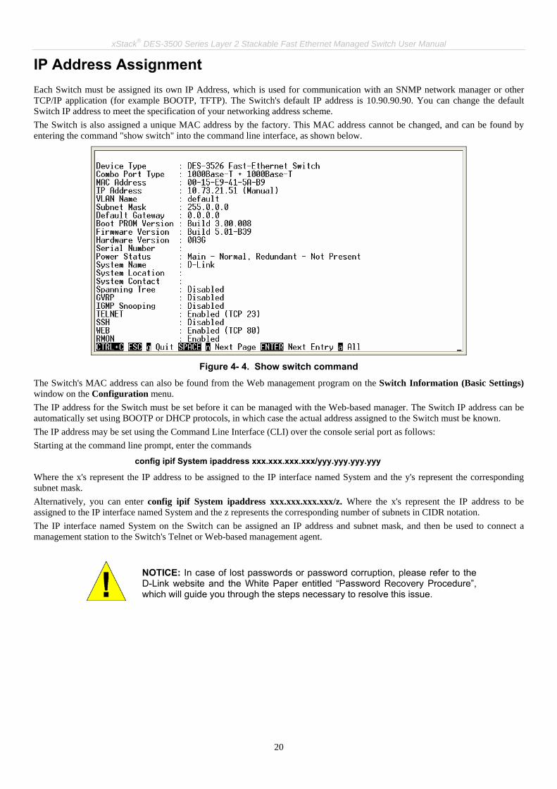
xStack® DES-3500 Series Layer 2 Stackable Fast Ethernet Managed Switch User Manual
20
IP Address Assignment Each Switch must be assigned its own IP Address, which is used for communication with an SNMP network manager or other TCP/IP application (for example BOOTP, TFTP). The Switch's default IP address is 10.90.90.90. You can change the default Switch IP address to meet the specification of your networking address scheme. The Switch is also assigned a unique MAC address by the factory. This MAC address cannot be changed, and can be found by entering the command "show switch" into the command line interface, as shown below.
Figure 4- 4. Show switch command
The Switch's MAC address can also be found from the Web management program on the Switch Information (Basic Settings) window on the Configuration menu. The IP address for the Switch must be set before it can be managed with the Web-based manager. The Switch IP address can be automatically set using BOOTP or DHCP protocols, in which case the actual address assigned to the Switch must be known. The IP address may be set using the Command Line Interface (CLI) over the console serial port as follows: Starting at the command line prompt, enter the commands
config ipif System ipaddress xxx.xxx.xxx.xxx/yyy.yyy.yyy.yyy
Where the x's represent the IP address to be assigned to the IP interface named System and the y's represent the corresponding subnet mask. Alternatively, you can enter config ipif System ipaddress xxx.xxx.xxx.xxx/z. Where the x's represent the IP address to be assigned to the IP interface named System and the z represents the corresponding number of subnets in CIDR notation. The IP interface named System on the Switch can be assigned an IP address and subnet mask, and then be used to connect a management station to the Switch's Telnet or Web-based management agent.
NOTICE: In case of lost passwords or password corruption, please refer to the D-Link website and the White Paper entitled “Password Recovery Procedure”, which will guide you through the steps necessary to resolve this issue.

xStack® DES-3500 Series Layer 2 Stackable Fast Ethernet Managed Switch User Manual
21
Figure 4- 5. Assigning the Switch an IP Address
In the above example, the Switch was assigned an IP address of 10.41.44.254 with a subnet mask of 255.0.0.0. The system message Success indicates that the command was executed successfully. The Switch can now be configured and managed via Telnet and the CLI or via the Web-based management.
Connecting Devices to the Switch After you assign IP addresses to the Switch, you can connect devices to the Switch. To connect a device to an SFP transceiver port:
• Use your cabling requirements to select an appropriate SFP transceiver type.
• Insert the SFP transceiver (sold separately) into the SFP transceiver slot.
• Use the appropriate network cabling to connect a device to the connectors on the SFP transceiver.
NOTICE: When the SFP transceiver acquires a link, the associated integrated 10/100/1000BASE-T port is disabled.

xStack® DES-3500 Series Layer 2 Stackable Fast Ethernet Managed Switch User Manual
22
Section 5 Web-based Switch Configuration
Introduction
Login to Web manager
Web-Based User Interface
Basic Setup
Reboot
Basic Switch Setup
Network Management
Switch Utilities
Network Monitoring
IGMP Snooping Status
Introduction All software functions of the DES-3500 Series switches can be managed, configured and monitored via the embedded web-based (HTML) interface. The Switch can be managed from remote stations anywhere on the network through a standard browser such as Opera, Netscape Navigator/Communicator, or Microsoft Internet Explorer. The browser acts as a universal access tool and can communicate directly with the Switch using the HTTP protocol. The Web-based management module and the Console program (and Telnet) are different ways to access the same internal switching software and configure it. Thus, all settings encountered in web-based management are the same as those found in the console program.
Login to Web Manager To begin managing your Switch, simply run the browser you have installed on your computer and point it to the IP address you have defined for the device. The URL in the address bar should read something like: http://123.123.123.123, where the numbers 123 represent the IP address of the Switch.
NOTE: The Factory default IP address for the Switch is 10.90.90.90.
This opens the management module's user authentication window, as seen below.

xStack® DES-3500 Series Layer 2 Stackable Fast Ethernet Managed Switch User Manual
23
Figure 5- 1. Enter Network Password window
Leave both the User Name field and the Password field blank and click OK. This will open the Web-based user interface. The Switch management features available in the web-based manager are explained below.
Web-based User Interface The user interface provides access to various Switch configuration and management screens, allows you to view performance statistics, and permits you to graphically monitor the system status.
Areas of the User Interface The figure below shows the user interface. The user interface is divided into three distinct areas as described in the table.
Figure 5- 2. Main Web-Manager page
Area Function
Area 1 Select the menu or window to be displayed. The folder icons can be opened to display the hyper-linked menu buttons and subfolders contained within them. Click the D-Link logo to go to the D-Link website.
Area 2 Presents a graphical near real-time image of the front panel of the Switch. This area displays the Switch's ports and expansion modules, showing port activity, duplex mode, or flow control, depending on the specified mode.
Area 1
Area 2
Area 3

xStack® DES-3500 Series Layer 2 Stackable Fast Ethernet Managed Switch User Manual
24
Various areas of the graphic can be selected for performing management functions, including port configuration.
Area 3 Presents switch information based on your selection and the entry of configuration data.
NOTICE: Any changes made to the Switch configuration during the current session must be saved in the Save Changes web menu (explained below) or use the command line interface (CLI) command save.
Web Pages When you connect to the management mode of the Switch with a web browser, a login window is displayed. Enter a user name and password to access the Switch's management mode. Below is a list and description of the main folders available in the web interface: Configuration – Contains windows concerning configurations for Switch Information, IP Address, Advanced Settings, Port Configuration, Port Description, Port Mirroring, Link Aggregation, LACP Port Setting, MAC Notification, IGMP, Spanning Tree, Loopback Detection, Forwarding Filtering, VLANs, Traffic Control, Port Security, QoS, System Severity Settings, System Log Server, SNTP Settings, ACL, Time Range Settings, IP-MAC Binding, Limited IP Multicast Range and Layer 3 IP Networking and LLDP. Security Management – Contains windows concerning configurations for Security including Trusted Host, User Accounts, Port Access Entity, Access Authentication Control, Secure Sockets Layer (SSL), Secure Shell (SSH), SNMP Manager, Safeguard Engine Settings, Filter and ARP Spoofing Prevention. Monitoring – Contains windows concerning monitoring the Switch, pertaining to Port Utilization, CPU Utilization, Memory Usage, Packets, Errors, Size, MAC Address, Switch History Log, IGMP Snooping Group, IGMP Snooping Forwarding, VLAN Status, Router Port, Port Access Control, Layer 3 Feature, Safeguard Engine Status and Cable Diagnostics. Maintenance – Contains windows concerning configurations and information about Switch maintenance, including TFTP Services, Multiple Image Services, Ping Test, Save Changes, Reset, Reset System, Reset Config, Reboot Device and Logout. Single IP Management – Contains windows concerning information on Single IP Management, including SIM Settings, Topology, and Firmware/Configuration downloads.
NOTE: Be sure to configure the user name and password in the User Accounts menu before connecting the Switch to the greater network.
NOTICE: In case of lost passwords or password corruption, please refer to the D-Link website and the White Paper entitled “Password Recovery Procedure”, which will guide you through the steps necessary to resolve this issue.

xStack® DES-3500 Series Layer 2 Stackable Fast Ethernet Managed Switch User Manual
25
Section 6 Configuring the Switch
Switch Information
IP Address
Advanced Settings
Port Configuration
Port Description
Port Mirroring
Link Aggregation
LACP Port Setting
MAC Notification
IGMP
Spanning Tree
Forward Filtering
VLANs
Traffic Control
Port Security
QoS
System Severity Settings
System Log Server
SNTP Settings
ACL
Time Range Settings
IP-MAC Binding
Limited IP Multicast Range Settings
Layer 3 IP Networking
LLDP

xStack® DES-3500 Series Layer 2 Stackable Fast Ethernet Managed Switch User Manual
26
Switch Information The subsections below describe how to change some of the basic settings for the Switch such as changing IP settings and assigning user names and passwords for management access privileges, as well as how to save the changes and restart the Switch. Click, Configuration > Switch Information to view the following window.
Figure 6- 1. Switch Information (Basic Settings) window
The Switch Information (Basic Settings) window shows the Switch's MAC Address (assigned by the factory and unchangeable), the Boot PROM, Firmware Version, and Hardware Version. This information is helpful to keep track of PROM and firmware updates and to obtain the Switch's MAC address for entry into another network device's address table, if necessary. The user may also enter a System Name, System Location and System Contact to aid in defining the Switch, to the user's preference.
IP Address The IP Address may initially be set using the console interface prior to connecting to it through the Ethernet. If the Switch IP address has not yet been changed, read the introduction of the xStack® DES-3500 Series Command Line Interface Manual or return to Section 4 of this manual for more information. To change IP settings using the web manager you must access the IP Address menu located in the Configuration folder. To configure the Switch's IP address: Open the Configuration folder and click the IP Address menu link. The web manager will display the Switch's current IP settings in the IP configuration menu, as seen below.

xStack® DES-3500 Series Layer 2 Stackable Fast Ethernet Managed Switch User Manual
27
Figure 6- 2. IP Address Settings window
To manually assign the Switch's IP address, subnet mask, and default gateway address: 1. Select Manual from the Get IP From drop-down menu. 2. Enter the appropriate IP Address and Subnet Mask. 3. If you want to access the Switch from a different subnet from the one it is installed on, enter the IP address of the Default
Gateway. If you will manage the Switch from the subnet on which it is installed, you can leave the default address (0.0.0.0) in this field.
4. If no VLANs have been previously configured on the Switch, you can use the default VLAN Name. The default VLAN contains all of the Switch ports as members. If VLANs have been previously configured on the Switch, you will need to enter the VLAN ID of the VLAN that contains the port connected to the management station that will access the Switch. The Switch will allow management access from stations with the same VID listed here.
NOTE: The Switch's factory default IP address is 10.90.90.90 with a subnet mask of 255.0.0.0 and a default gateway of 0.0.0.0.
To use the BOOTP or DHCP protocols to assign the Switch an IP address, subnet mask, and default gateway address. Use the Get IP From pull-down menu to choose from BOOTP or DHCP. This selects how the Switch will be assigned an IP address on the next reboot.
NOTE: If you enable the AutoConfig, the Get IP From setting will automatically become DHCP.
The IP Address Settings options are:
Parameter Description
BOOTP The Switch will send out a BOOTP broadcast request when it is powered up. The BOOTP protocol allows IP addresses, network masks, and default gateways to be assigned by a central BOOTP server. If this option is set, the Switch will first look for a BOOTP server to provide it with this information before using the default or previously entered settings.
DHCP The Switch will send out a DHCP broadcast request when it is powered up. The DHCP protocol allows IP addresses, network masks, and default gateways to be assigned by a DHCP server. If this option is set, the Switch will first look for a DHCP server to provide it with this information before using the default or previously entered settings.
Manual Allows the entry of an IP address, Subnet Mask, and a Default Gateway for the Switch. These fields should be of the form xxx.xxx.xxx.xxx, where each xxx is a number (represented in decimal form) between 0 and 255. This address should be a unique address on the network assigned for use by the network administrator.
Subnet Mask A Bitmask that determines the extent of the subnet that the Switch is on. Should be of the form xxx.xxx.xxx.xxx, where each xxx is a number (represented in decimal) between 0 and 255. The value should be 255.0.0.0 for a Class A network, 255.255.0.0 for a Class B network, and

xStack® DES-3500 Series Layer 2 Stackable Fast Ethernet Managed Switch User Manual
28
255.255.255.0 for a Class C network, but custom subnet masks are allowed.
Default Gateway
IP address that determines where packets with a destination address outside the current subnet should be sent. This is usually the address of a router or a host acting as an IP gateway. If your network is not part of an intranet, or you do not want the Switch to be accessible outside your local network, you can leave this field unchanged.
VLAN Name This allows the entry of a VLAN Name from which a management station will be allowed to manage the Switch using TCP/IP (in-band via web manager or Telnet). Management stations that are on VLANs other than the one entered here will not be able to manage the Switch in-band unless their IP addresses are entered in the Security IP Management menu. If VLANs have not yet been configured for the Switch, the default VLAN contains all of the Switch's ports. There are no entries in the Security IP Management table, by default, so any management station that can connect to the Switch can access the Switch until a management VLAN is specified or Management Station IP Addresses are assigned.
Admin State This allows the user to enable or disable the Admin State for the IP interface, by the using the pull-down menu. Disabling this feature will render all remote management inoperable, and thus the only way to configure the Switch will be to use the Console port for the Command Line Interface.
Auto Config State
When autoconfig is enabled, the Switch is instructed to get a configuration file via TFTP, and it becomes a DHCP client automatically. The configuration file will be loaded upon booting up. In order to use Auto Config, the DHCP server must be set up to deliver the TFTP server IP address and configuration file name information in the DHCP reply packet. The TFTP server must be running and have the requested configuration file stored in its base directory when the request is received from the Switch. Consult the DHCP server and/or TFTP server software instructions for information on loading a configuration file for use by a client. (Also see the section titled Upload Configuration for instructions on uploading a configuration to a TFTP server. If the Switch is unable to complete the autoconfiguration process the previously saved configuration file present in Switch memory will be loaded.
Click Apply to let your changes take effect.

xStack® DES-3500 Series Layer 2 Stackable Fast Ethernet Managed Switch User Manual
29
NOTICE: In case of lost passwords or password corruption, please refer to the D-Link website and the White Paper entitled “Password Recovery Procedure”, which will guide you through the steps necessary to resolve this issue.

xStack® DES-3500 Series Layer 2 Stackable Fast Ethernet Managed Switch User Manual
30
Advanced Settings The Switch Information (Advanced Settings) window contains the main settings for all major functions for the Switch. To view this window click, Configuration > Advanced Settings.
Figure 6- 3. Switch Information (Advanced Settings) window
Parameter Description
Serial Port Auto Logout Time
Select the logout time used for the console interface. This automatically logs the user out after an idle period of time, as defined. Choose from the following options: 2 Minutes, 5 Minutes, 10 Minutes, 15 Minutes or Never. The default setting is 10 minutes.
MAC Address Aging Time
This field specifies the length of time a learned MAC Address will remain in the forwarding table without being accessed (that is, how long a learned MAC Address is allowed to remain idle). To change this, enter a different value representing the MAC address age-out time in seconds. The MAC Address Aging Time can be set to any value between 10 and 1,000,000 seconds. The default setting is 300 seconds.
IGMP Snooping To enable system-wide IGMP Snooping capability select Enabled. IGMP snooping is Disabled by default. Enabling IGMP snooping allows you to specify use of a multicast router only (see below). To configure IGMP Snooping for individual VLANs, use the IGMP Snooping window under the IGMP folder.
GVRP Status Use this pull-down menu to enable or disable GVRP on the Switch. Telnet Status Telnet configuration is Enabled by default. If you do not want to allow configuration of the
system through Telnet choose Disabled. TCP Port Number (1-65535)
The TCP port number. TCP ports are numbered between 1 and 65535. The "well-known" TCP port for the Telnet protocol is 23.
Web Status Web-based management is Enabled by default. If you choose to disable this by selecting Disabled, you will lose the ability to configure the system through the web interface as soon as these settings are applied.
Web TCP Port The TCP port number currently being utilized by the Switch to connect to the web interface.

xStack® DES-3500 Series Layer 2 Stackable Fast Ethernet Managed Switch User Manual
31
Number The "well-known" TCP port for the Web interface is 80. Link Aggregation Algorithm
The algorithm that the Switch uses to balance the load across the ports that make up the port trunk group is defined by this definition. Choose MAC Source, MAC Destination, MAC Src & Dest, IP Source, IP Destination or IP Src & Dest (See the Link Aggregation section of this manual).
RMON Status Remote monitoring (RMON) of the Switch is Enabled or Disabled here. 802.1x Status MAC Address may enable by port or the Switch’s 802.1x function; the default is Disabled.
This field must be enabled to view and configure certain windows for 802.1x. More information regarding 802.1x, its functions and implementation can be found later in this section, under the Port Access Entity folder. Port-Based 802.1x specifies that ports configured for 802.1x are initialized based on the port number only and are subject to any authorization parameters configured. MAC-based Authorization specifies that ports configured for 802.1x are initialized based on the port number and the MAC address of the computer being authorized and are then subject to any authorization parameters configured.
802.1x Authentication Protocol
The user may use the pull-down menu to choose between radius eap and radius pap for the 802.1x authentication protocol on the Switch. The default setting is radius eap.
Asymmetric VLAN This field will enable or disable Asymmetric VLANs on the Switch. The default is Disabled. Syslog Global State Enables or disables Syslog State; default is Disabled.
Click Apply to implement changes made.
NOTE: When the Asymmetric VLAN function is Disabled, the user must change the VLAN setting on the Switch to its default configurations.

xStack® DES-3500 Series Layer 2 Stackable Fast Ethernet Managed Switch User Manual
32
Port Configuration This section contains information for configuring various attributes and properties for individual physical ports and Err-disabled Ports, including port speed and flow control. To display the following window click, Configuration > Port Configuration.
Figure 6- 4. Port Configuration window
To configure switch ports: 1. Choose the port or sequential range of ports using the From…To… port pull-down menus. 2. Use the remaining pull-down menus to configure the parameters described below:
Parameter Description
State Toggle the State field to either enable or disable a given port or group of ports.
MDIX Medium dependent interface crossover is a female port connection on the Switch used to connect to end stations, servers and hubs. The drop down menu allows the user to choose

xStack® DES-3500 Series Layer 2 Stackable Fast Ethernet Managed Switch User Manual
33
between Auto, Normal or Cross. Auto will automatically switch to the proper configuration once a cable is connected. Normal will be selected if a straight-through cable is being used and Cross should be selected if a crossover cable is being used.
Speed/Duplex Toggle the Speed/Duplex field to either select the speed and duplex/half-duplex state of the port. Auto denotes auto-negotiation between 10 and 100 Mbps devices, in full- or half-duplex. The Auto setting allows the port to automatically determine the fastest settings the device the port is connected to can handle, and then to use those settings. The other options are Auto, 10M/Half, 10M/Full, 100M/Half, 100M/Full, and 1000M/Full. There is no automatic adjustment of port settings with any option other than Auto.
Flow Control Displays the flow control scheme used for the various port configurations. Ports configured for full-duplex use 802.3x flow control, half-duplex ports use backpressure flow control, and Auto ports use an automatic selection of the two. The default is Disabled.
Learn Enable or disable MAC address learning for the selected ports. When Enabled, destination and source MAC addresses are automatically listed in the forwarding table. When learning is Dis-abled, MAC addresses must be manually entered into the forwarding table. This is sometimes done for reasons of security or efficiency. See the section on Forwarding/Filtering for information on entering MAC addresses into the forwarding table. The default setting is Disabled.
Trap Enables or disables trap support on the switch. The default setting is Disabled.
Click Apply to implement the new settings on the Switch.

xStack® DES-3500 Series Layer 2 Stackable Fast Ethernet Managed Switch User Manual
34
Port Description The DES-3500 Series switches support a port description feature where the user may name various ports on the Switch. To assign names to various ports, click Configuration > Port Description:
Figure 6- 5. Port Description Settings window
Use the From and To pull down menu to choose a port or range of ports and enter a description of the port(s). Click Apply to set the descriptions in the Port Description Table.

xStack® DES-3500 Series Layer 2 Stackable Fast Ethernet Managed Switch User Manual
35
Port Mirroring The Switch allows you to copy frames transmitted and received on a port and redirect the copies to another port. You can attach a monitoring device to the mirrored port, such as a sniffer or an RMON probe, to view details about the packets passing through the first port. This is useful for network monitoring and troubleshooting purposes. To view the Port Mirroring window, click Configuration > Port Mirroring.
Figure 6- 6. Setup Port Mirroring window
To configure a mirror port:
• Select the Source Port from where you want to copy frames and the Target Port, which receives the copies from the source port.
• Select the Source Direction, Ingress, Egress, or Both and change the Status drop-down menu to Enabled.
• Click Apply to let the changes take effect.
NOTE: You cannot mirror a fast port onto a slower port. For example, if you try to mirror the traffic from a 100 Mbps port onto a 10 Mbps port, this can cause throughput problems. The port you are copying frames from should always support an equal or lower speed than the port to which you are sending the copies. Also, the target port for the mirroring cannot be a member of a trunk group. Please note a target port and a source port cannot be the same port.

xStack® DES-3500 Series Layer 2 Stackable Fast Ethernet Managed Switch User Manual
36
Link Aggregation Understanding Port Trunk Groups Port trunk groups are used to combine a number of ports together to make a single high-bandwidth data pipeline. The DES-3500 Series switches support up to six port trunk groups with 2 to 8 ports in each group. A potential bit rate of 8000 Mbps can be achieved.
Figure 6- 7. Example of Port Trunk Group

xStack® DES-3500 Series Layer 2 Stackable Fast Ethernet Managed Switch User Manual
37
The Switch treats all ports in a trunk group as a single port. Data transmitted to a specific host (destination address) will always be transmitted over the same port in a trunk group. This allows packets in a data stream to arrive in the same order they were sent.
NOTE: If any ports within the trunk group become disconnected, packets intended for the discon-nected port will be load shared among the other unlinked ports of the link aggregation group.
Link aggregation allows several ports to be grouped together and to act as a single link. This gives a bandwidth that is a multiple of a single link's bandwidth. Link aggregation is most commonly used to link a bandwidth intensive network device or devices, such as a server, to the backbone of a network. The Switch allows the creation of up to six link aggregation groups, each group consisting of 2 to 8 links (ports). The aggregated links must be contiguous (they must have sequential port numbers) except the two (optional) Gigabit ports, which can only belong to a single link aggregation group. All of the ports in the group must be members of the same VLAN, and their STP status, static multicast, traffic control; traffic segmentation and 802.1p default priority configurations must be identical. Port locking, port mirroring and 802.1X must not be enabled on the trunk group. Further, the aggregated links must all be of the same speed and should be configured as full duplex. The Master Port of the group is to be configured by the user, and all configuration options, including the VLAN configuration that can be applied to the Master Port, are applied to the entire link aggregation group. Load balancing is automatically applied to the ports in the aggregated group, and a link failure within the group causes the network traffic to be directed to the remaining links in the group. The Spanning Tree Protocol will treat a link aggregation group as a single link, on the switch level. On the port level, the STP will use the port parameters of the Master Port in the calculation of port cost and in determining the state of the link aggregation group. If two redundant link aggregation groups are configured on the Switch, STP will block one entire group; in the same way STP will block a single port that has a redundant link. To configure port trunking, click Configuration > Link Aggregation to view the following window:
Figure 6- 8. Port Link Aggregation Group window
To configure port trunk groups, click the Add button to add a new trunk group and use the Link Aggregation Settings window (see example below) to set up trunk groups. To modify a port trunk group, click the Modify button corresponding to the entry you wish to alter. To delete a port trunk group, click the corresponding X under the Delete heading in the Current Link Aggregation Group Entries table.
Figure 6- 9. Link Aggregation Settings window – Add

xStack® DES-3500 Series Layer 2 Stackable Fast Ethernet Managed Switch User Manual
38
Figure 6- 10. Link Aggregation Settings window - Modify
The user-changeable parameters are as follows:
Parameter Description
Group ID Select an ID number for the group, between 1 and 6.
State Trunk groups can be toggled between Enabled and Disabled. This is used to turn a port trunking group on or off. This is useful for diagnostics, to quickly isolate a bandwidth intensive network device or to have an absolute backup aggregation group that is not under automatic control.
Master Port Choose the Master Port for the trunk group using the pull-down menu.
Member Ports Choose the members of a trunked group. Up to eight ports per group can be assigned to a group.
Flooding Port A trunking group must designate one port to allow transmission of broadcasts and unknown unicasts.
Active Port Shows the port that is currently forwarding packets.
Type This pull-down menu allows you to select between Static and LACP (Link Aggregation Control Protocol). LACP allows for the automatic detection of links in a Port Trunking Group.
After setting the previous parameters, click Apply to allow your changes to be implemented. Successfully created trunk groups will be show in the Current Link Aggregation Group Entries table as seen in Figure 6-8.

xStack® DES-3500 Series Layer 2 Stackable Fast Ethernet Managed Switch User Manual
39
LACP Port Setting The LACP Port Setting window is used in conjunction with the Link Aggregation window to create port trunking groups on the Switch. Using the following window, the user may set which ports will be active and passive in processing and sending LACP control frames. To view this window, click Configuration > LACP Port Setting.
Figure 6- 11. LACP Port Settings window
The user may set the following parameters:
Parameter Description
From/To A consecutive group of ports may be configured starting with the selected port.
Mode Active - Active LACP ports are capable of processing and sending LACP control frames. This allows LACP compliant devices to negotiate the aggregated link so the group may be changed dynamically as needs require. In order to utilize the ability to change an aggregated port group, that is, to add or subtract ports from the group, at least one of the participating devices must designate LACP ports as active. Both devices must support LACP. Passive - LACP ports that are designated as passive cannot initially send LACP control frames. In order to allow the linked port group to negotiate adjustments and make changes

xStack® DES-3500 Series Layer 2 Stackable Fast Ethernet Managed Switch User Manual
40
dynamically, one end of the connection must have "active" LACP ports (see above).
After setting the previous parameters, click Apply to allow your changes to be implemented. The LACP Port Table shows which ports are active and/or passive.
MAC Notification MAC Notification is used to monitor MAC addresses learned and entered into the forwarding database.
MAC Notification Global Settings To globally set MAC notification on the Switch, open the following window by opening Configuration > MAC Notification > MAC Notification Global Settings:
Figure 6- 12. MAC Notification Global Settings window
The following parameters may be modified:
Parameter Description
State Enable or disable MAC notification globally on the Switch
Interval (sec) The time in seconds between notifications.
History size The maximum number of entries listed in the history log used for notification. Up to 500 entries can be specified.

xStack® DES-3500 Series Layer 2 Stackable Fast Ethernet Managed Switch User Manual
41
MAC Notification Port Settings To change MAC notification settings for a port or group of ports on the Switch, click Configuration > MAC Notification > MAC Notification Port Settings, which will display the following window:
Figure 6- 13. MAC Notification Port Settings window
The following parameters may be set:
Parameter Description
From…To Select a port or group of ports to enable for MAC notification using the pull-down menus.
State Enable MAC Notification for the ports selected using the pull-down menu.
Click Apply to implement changes made.

xStack® DES-3500 Series Layer 2 Stackable Fast Ethernet Managed Switch User Manual
42
IGMP Internet Group Management Protocol (IGMP) snooping allows the Switch to recognize IGMP queries and reports sent between network stations or devices and an IGMP host. When enabled for IGMP snooping, the Switch can open or close a port to a specific device based on IGMP messages passing through the Switch. In order to use IGMP Snooping it must first be enabled for the entire Switch (see Advanced Settings). You may then fine-tune the settings for each VLAN using the IGMP Snooping link in the Configuration folder. When enabled for IGMP snooping, the Switch can open or close a port to a specific multicast group member based on IGMP messages sent from the device to the IGMP host or vice versa. The Switch monitors IGMP messages and discontinues forwarding multicast packets when there are no longer hosts requesting that they continue.
IGMP Snooping Use the Current IGMP Snooping Group Entries window to view IGMP Snooping settings. To modify the settings, click the Modify button of the VLAN ID you want to change. To view this window click, Configuration > IGMP > IGMP Snooping.
Figure 6- 14. Current IGMP Snooping Group Entries window
Clicking the Modify button will open the IGMP Snooping Settings window, shown below:
Figure 6- 15. IGMP Snooping Settings window

xStack® DES-3500 Series Layer 2 Stackable Fast Ethernet Managed Switch User Manual
43
The following parameters may be viewed or modified:
Parameter Description
VLAN ID This is the VLAN ID that, along with the VLAN Name, identifies the VLAN the user wishes to modify the IGMP Snooping Settings for.
VLAN Name This is the VLAN Name that, along with the VLAN ID, identifies the VLAN the user wishes to modify the IGMP Snooping Settings for.
Query Interval The Query Interval field is used to set the time (in seconds) between transmitting IGMP queries. Entries between 1 and 65535 seconds are allowed. Default = 125.
Max Response Time This determines the maximum amount of time in seconds allowed before sending an IGMP response report. The Max Response Time field allows an entry between 1 and 25 (seconds). Default = 10.
Robustness Variable Adjust this variable according to expected packet loss. If packet loss on the VLAN is expected to be high, the Robustness Variable should be increased to accommodate increased packet loss. This entry field allows an entry of 1 to 255. Default = 2.
Last Member Query Interval
This field specifies the maximum amount of time between group-specific query messages, including those sent in response to leave group messages. Default = 1.
Host Timeout This is the maximum amount of time in seconds allowed for a host to continue membership in a multicast group without the Switch receiving a host membership report. Default = 260.
Router Timeout This is the maximum amount of time in seconds a route is kept in the forwarding table without receiving a membership report. Default = 260.
Leave Timer This specifies the maximum amount of time in seconds between the Switch receiving a leave group message from a host, and the Switch issuing a group membership query. If no response to the membership query is received before the Leave Timer expires, the (multicast) forwarding entry for that host is deleted.
Querier State Choose Enabled to enable transmitting IGMP Query packets or Disabled to disable. The default is Disabled.
State Select Enabled to implement IGMP Snooping. This field is Disabled by default.
Click Apply to implement the new settings. Click the Show All IGMP Group Entries link to return to the Current IGMP Snooping Group Entries window.

xStack® DES-3500 Series Layer 2 Stackable Fast Ethernet Managed Switch User Manual
44
Static Router Ports Entry A static router port is a port that has a multicast router attached to it. Generally, this router would have a connection to a WAN or to the Internet. Establishing a router port will allow multicast packets coming from the router to be propagated through the network, as well as allowing multicast messages (IGMP) coming from the network to be propagated to the router. A router port has the following behavior:
• All IGMP Report packets will be forwarded to the router port.
• IGMP queries (from the router port) will be flooded to all ports.
• All UDP multicast packets will be forwarded to the router port. Because routers do not send IGMP reports or implement IGMP snooping, a multicast router connected to the router port of a Layer 3 switch would not be able to receive UDP data streams unless the UDP multicast packets were all forwarded to the router port.
A router port will be dynamically configured when IGMP query packets, RIPv2 multicast, DVMRP multicast or PIM-DM multicast packets are detected flowing into a port. To view this window click, Configuration > IGMP > Static Router Ports Entry.
Figure 6- 16. Current Static Router Ports Entries window
The Current Static Router Ports Entries window displays all of the current entries to the Switch's static router port table. To modify an entry, click the Modify button. This will open the Static Router Ports Settings window, as shown below.
Figure 6- 17. Static Router Ports Settings window
The following parameters can be set:
Parameter Description
VID (VLAN ID) This is the VLAN ID that, along with the VLAN Name, identifies the VLAN where the multicast router is attached.
VLAN Name This is the name of the VLAN where the multicast router is attached.
Member Ports Ports on the Switch that will have a multicast router attached to them.
Click Apply to implement the new settings, Click the Show All Static Router Port Entries link to return to the Current Static Router Port Entries window.

xStack® DES-3500 Series Layer 2 Stackable Fast Ethernet Managed Switch User Manual
45
Forbidden Router Ports Entry The Forbidden Router Ports Entry section will allow users to set a port or group of ports belonging to a VLAN as being forbidden from receiving information from or being connected to multicast routers. To view the following window, click Configuration > IGMP > Forbidden Router Ports Entry.
Figure 6- 18. Current Forbidden MC Router Ports Entries
To change the forbidden router ports settings for a listed VLAN, click its corresponding Modify button, which will display the following configurable window.
Figure 6- 19. Forbidden MC Router Ports Settings
To add ports as forbidden router ports, click the corresponding check box of the port or ports, and click Apply. Properly set forbidden ports will be displayed in the Current Forbidden MC Router Ports Entries window under the Port List heading.
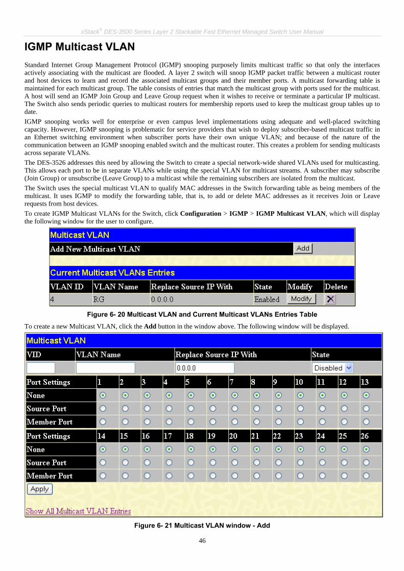
xStack® DES-3500 Series Layer 2 Stackable Fast Ethernet Managed Switch User Manual
46
IGMP Multicast VLAN Standard Internet Group Management Protocol (IGMP) snooping purposely limits multicast traffic so that only the interfaces actively associating with the multicast are flooded. A layer 2 switch will snoop IGMP packet traffic between a multicast router and host devices to learn and record the associated multicast groups and their member ports. A multicast forwarding table is maintained for each multicast group. The table consists of entries that match the multicast group with ports used for the multicast. A host will send an IGMP Join Group and Leave Group request when it wishes to receive or terminate a particular IP multicast. The Switch also sends periodic queries to multicast routers for membership reports used to keep the multicast group tables up to date. IGMP snooping works well for enterprise or even campus level implementations using adequate and well-placed switching capacity. However, IGMP snooping is problematic for service providers that wish to deploy subscriber-based multicast traffic in an Ethernet switching environment when subscriber ports have their own unique VLAN; and because of the nature of the communication between an IGMP snooping enabled switch and the multicast router. This creates a problem for sending multicasts across separate VLANs. The DES-3526 addresses this need by allowing the Switch to create a special network-wide shared VLANs used for multicasting. This allows each port to be in separate VLANs while using the special VLAN for multicast streams. A subscriber may subscribe (Join Group) or unsubscribe (Leave Group) to a multicast while the remaining subscribers are isolated from the multicast. The Switch uses the special multicast VLAN to qualify MAC addresses in the Switch forwarding table as being members of the multicast. It uses IGMP to modify the forwarding table, that is, to add or delete MAC addresses as it receives Join or Leave requests from host devices. To create IGMP Multicast VLANs for the Switch, click Configuration > IGMP > IGMP Multicast VLAN, which will display the following window for the user to configure.
Figure 6- 20 Multicast VLAN and Current Multicast VLANs Entries Table
To create a new Multicast VLAN, click the Add button in the window above. The following window will be displayed.
Figure 6- 21 Multicast VLAN window - Add

xStack® DES-3500 Series Layer 2 Stackable Fast Ethernet Managed Switch User Manual
47
The following parameters can be set:
Parameter Description
VID The VLAN ID of the multicast VLAN to be created. The user may choose a number between 1-4094 to identify this VLAN. Up to 3 multicast VLANs can be configured.
VLAN Name The name of the multicast VLAN to be configured. Each multicast VLAN is given a name that can be up to 32 characters. Up to 3 multicast VLANs can be configured.
Replace Source IP With
Enter a source IP address that you want to replace.
State The user may enable or disable this VLAN using the pull down menu here.
Source Port A port on the Switch to be designated as the source port for multicast traffic. Multicast traffic entering the switch will be forwarded from this port to member ports on the same VLAN. Note that the Source port must be different from the member ports of the created VLAN.
Member Port A port or range of member ports to add to the multicast VLAN. These ports will receive multicast traffic from the source port. Remember, the source port cannot be the same as any member port.
Click Apply to create the multicast VLAN. To modify a previously created multicast VLAN, click the Modify button in the Current Multicast VLANs Entries Table, which will display the following window for the user to configure.
Figure 6- 22 Multicast VLAN window - Modify
The following parameters can be set:
Parameter Description
VID Displays the VLAN ID of the configured multicast VLAN. Up to 3 multicast VLANs can be configured.
VLAN Name The name of the configured multicast VLAN. Each multicast VLAN is given a name that can be up to 32 characters. Up to 3 multicast VLANs can be configured.
Replace Source IP With
Enter a source IP address that you want to replace in this field.
State The user may enable or disable this VLAN using the pull down menu here.

xStack® DES-3500 Series Layer 2 Stackable Fast Ethernet Managed Switch User Manual
48
Source Port A port on the Switch to be designated as the source port for multicast traffic. Multicast traffic entering the switch will be forwarded from this port to member ports on the same VLAN. Note that the Source port must be different from the member ports of the created VLAN.
Member Port A port or range of member ports to add to the multicast VLAN. These ports will receive multicast traffic from the source port. Remember, the source port cannot be the same as any member port.
Click Apply to configure the multicast VLAN.
Note: Once a Multicast VLAN has been configured and enabled on the switch, other IGMP Snooping settings will be overridden and the IGMP Snooping Multicast VLAN will take precedence.

xStack® DES-3500 Series Layer 2 Stackable Fast Ethernet Managed Switch User Manual
49
Spanning Tree This Switch supports three versions of the Spanning Tree Protocol; 802.1d STP, 802.1w Rapid STP and 802.1s MSTP. 802.1d STP will be familiar to most networking professionals. However, since 802.1w RSTP and 802.1s MSTP has been recently introduced to D-Link managed Ethernet switches, a brief introduction to the technology is provided below followed by a description of how to set up 802.1d STP, 802.1w RSTP and 802.1s MSTP.
802.1s MSTP Multiple Spanning Tree Protocol, or MSTP, is a standard defined by the IEEE community that allows multiple VLANs to be mapped to a single spanning tree instance, which will provide multiple pathways across the network. Therefore, these MSTP configurations will balance the traffic load, preventing wide scale disruptions when a single spanning tree instance fails. This will allow for faster convergences of new topologies for the failed instance. Frames designated for these VLANs will be processed quickly and completely throughout interconnected bridges utilizing any of the three spanning tree protocols (STP, RSTP or MSTP). This protocol will also tag BPDU packets so receiving devices can distinguish spanning tree instances, spanning tree regions and the VLANs associated with them. An MSTI ID will classify these instances. MSTP will connect multiple spanning trees with a Common and Internal Spanning Tree (CIST). The CIST will automatically determine each MSTP region, its maximum possible extent and will appear as one virtual bridge that runs a single spanning tree. Consequentially, frames assigned to different VLANs will follow different data routes within administratively established regions on the network, continuing to allow simple and full processing of frames, regardless of administrative errors in defining VLANs and their respective spanning trees. Each switch utilizing the MSTP on a network will have a single MSTP configuration that will have the following three attributes:
1. A configuration name defined by an alphanumeric string of up to 32 characters (defined in the STP Bridge Global Settings window in the Configuration Name field).
2. A configuration revision number (named here as a Revision Level and found in the STP Bridge Global Settings window) and;
3. A 4096-element table (defined here as a VID List in the MST Configuration Table window), which will associate each of the possible 4096, VLANs supported by the Switch for a given instance.
To utilize the MSTP function on the Switch, three steps need to be taken: 1. The Switch must be set to the MSTP setting (found in the STP Bridge Global Settings window in the STP Version field) 2. The correct spanning tree priority for the MSTP instance must be entered (defined here as a Priority in the MST
Configuration Table window when configuring an MSTI ID settings). 3. VLANs that will be shared must be added to the MSTP Instance ID (defined here as a VID List in the MST
Configuration Table window when configuring an MSTI ID settings).
802.1w Rapid Spanning Tree The Switch implements three versions of the Spanning Tree Protocol, the Multiple Spanning Tree Protocol (MSTP) as defined by the IEEE 802.1s, the Rapid Spanning Tree Protocol (RSTP) as defined by the IEEE 802.1w specification and a version compatible with the IEEE 802.1d STP. RSTP can operate with legacy equipment implementing IEEE 802.1d, however the advantages of using RSTP will be lost. The IEEE 802.1w Rapid Spanning Tree Protocol (RSTP) evolved from the 802.1d STP standard. RSTP was developed in order to overcome some limitations of STP that impede the function of some recent switching innovations, in particular, certain Layer 3 functions that are increasingly handled by Ethernet switches. The basic function and much of the terminology is the same as STP. Most of the settings configured for STP are also used for RSTP. This section introduces some new Spanning Tree concepts and illustrates the main differences between the two protocols.
Port Transition States An essential difference between the three protocols is in the way ports transition to a forwarding state and in the way this transition relates to the role of the port (forwarding or not forwarding) in the topology. MSTP and RSTP combine the transition states disabled, blocking and listening used in 802.1d and creates a single state Discarding. In either case, ports do not forward packets. In the STP port transition states disabled, blocking or listening or in the RSTP/MSTP port state discarding, there is no functional difference, the port is not active in the network topology. Table 6-1 below compares how the three protocols differ regarding the port state transition. All three protocols calculate a stable topology in the same way. Every segment will have a single path to the root bridge. All bridges listen for BPDU packets. However, BPDU packets are sent more frequently - with every Hello packet. BPDU packets are sent even if a BPDU packet was not received. Therefore, each link between bridges is sensitive to the status of the link. Ultimately this difference results in faster detection of failed links, and thus faster topology adjustment. A drawback of 802.1d is this absence of immediate feedback from adjacent bridges.

xStack® DES-3500 Series Layer 2 Stackable Fast Ethernet Managed Switch User Manual
50
802.1d MSTP 802.1w RSTP 802.1d STP Forwarding Learning
Discarding Discarding Disabled No No
Discarding Discarding Blocking No No
Discarding Discarding Listening No No
Learning Learning Learning No Yes
Forwarding Forwarding Forwarding Yes Yes
Table 6- 1. Comparing Port States RSTP is capable of a more rapid transition to a forwarding state - it no longer relies on timer configurations - RSTP compliant bridges are sensitive to feedback from other RSTP compliant bridge links. Ports do not need to wait for the topology to stabilize before transitioning to a forwarding state. In order to allow this rapid transition, the protocol introduces two new variables: the edge port and the point-to-point (P2P) port.
Edge Port The edge port is a configurable designation used for a port that is directly connected to a segment where a loop cannot be created. An example would be a port connected directly to a single workstation. Ports that are designated as edge ports transition to a forwarding state immediately without going through the listening and learning states. An edge port loses its status if it receives a BPDU packet, immediately becoming a normal spanning tree port.
P2P Port A P2P port is also capable of rapid transition. P2P ports may be used to connect to other bridges. Under RSTP/MSTP, all ports operating in full-duplex mode are considered to be P2P ports, unless manually overridden through configuration.
802.1d/802.1w/802.1s Compatibility MSTP or RSTP can interoperate with legacy equipment and is capable of automatically adjusting BPDU packets to 802.1d format when necessary. However, any segment using 802.1d STP will not benefit from the rapid transition and rapid topology change detection of MSTP or RSTP. The protocol also provides for a variable used for migration in the event that legacy equipment on a segment is updated to use RSTP or MSTP. The Spanning Tree Protocol (STP) operates on two levels:
1. On the switch level, the settings are globally implemented. 2. On the port level, the settings are implemented on a per user-defined group of ports basis.

xStack® DES-3500 Series Layer 2 Stackable Fast Ethernet Managed Switch User Manual
51
STP Bridge Global Settings To view the STP Bridge Global Settings, click Configuration > Spanning Tree > STP Bridge Global Settings.
Figure 6- 23. STP Bridge Global Settings window - STP

xStack® DES-3500 Series Layer 2 Stackable Fast Ethernet Managed Switch User Manual
52
Figure 6- 24. STP Bridge Global Settings window - RSTP (default)
Figure 6- 25. STP Bridge Global Settings window - MSTP
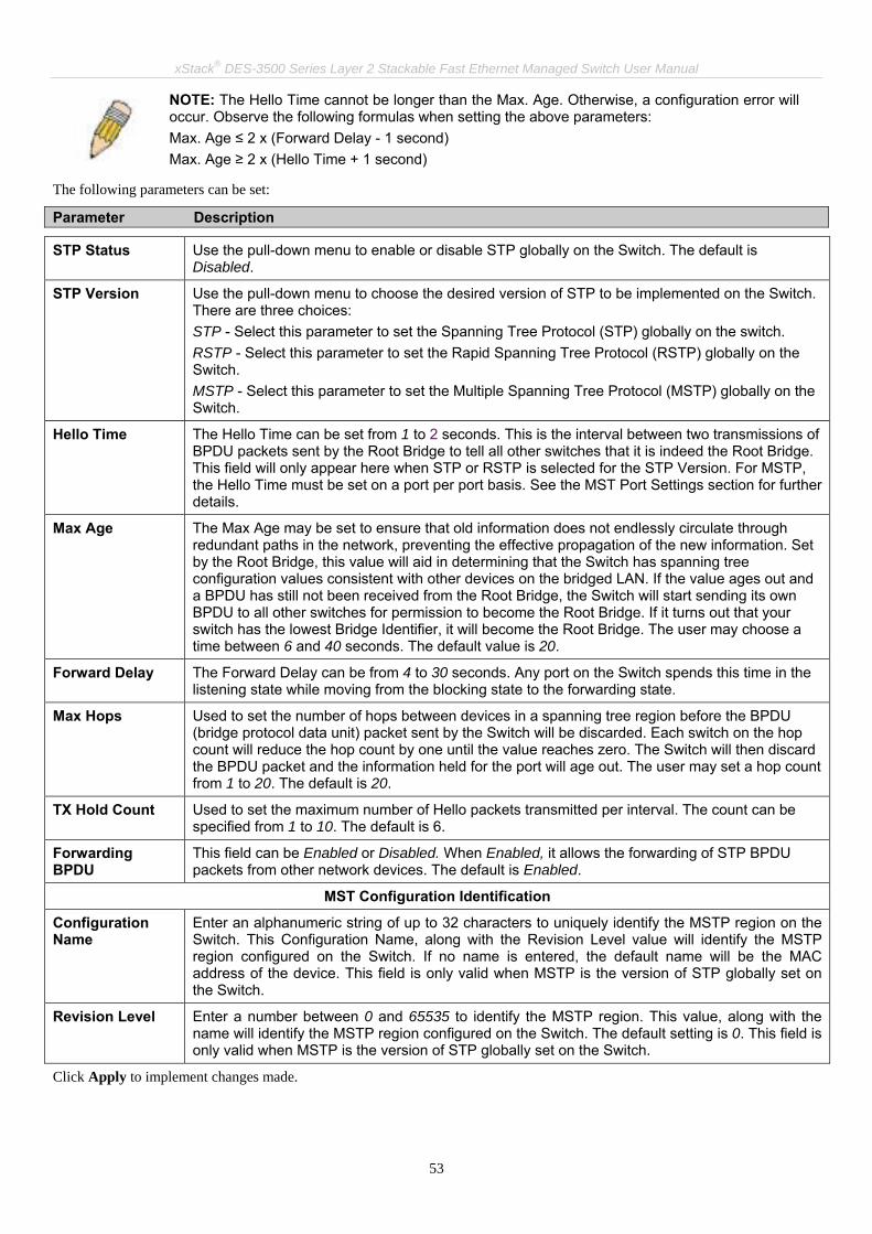
xStack® DES-3500 Series Layer 2 Stackable Fast Ethernet Managed Switch User Manual
53
NOTE: The Hello Time cannot be longer than the Max. Age. Otherwise, a configuration error will occur. Observe the following formulas when setting the above parameters: Max. Age ≤ 2 x (Forward Delay - 1 second) Max. Age ≥ 2 x (Hello Time + 1 second)
The following parameters can be set:
Parameter Description
STP Status Use the pull-down menu to enable or disable STP globally on the Switch. The default is Disabled.
STP Version Use the pull-down menu to choose the desired version of STP to be implemented on the Switch. There are three choices: STP - Select this parameter to set the Spanning Tree Protocol (STP) globally on the switch. RSTP - Select this parameter to set the Rapid Spanning Tree Protocol (RSTP) globally on the Switch. MSTP - Select this parameter to set the Multiple Spanning Tree Protocol (MSTP) globally on the Switch.
Hello Time The Hello Time can be set from 1 to 2 seconds. This is the interval between two transmissions of BPDU packets sent by the Root Bridge to tell all other switches that it is indeed the Root Bridge. This field will only appear here when STP or RSTP is selected for the STP Version. For MSTP, the Hello Time must be set on a port per port basis. See the MST Port Settings section for further details.
Max Age The Max Age may be set to ensure that old information does not endlessly circulate through redundant paths in the network, preventing the effective propagation of the new information. Set by the Root Bridge, this value will aid in determining that the Switch has spanning tree configuration values consistent with other devices on the bridged LAN. If the value ages out and a BPDU has still not been received from the Root Bridge, the Switch will start sending its own BPDU to all other switches for permission to become the Root Bridge. If it turns out that your switch has the lowest Bridge Identifier, it will become the Root Bridge. The user may choose a time between 6 and 40 seconds. The default value is 20.
Forward Delay The Forward Delay can be from 4 to 30 seconds. Any port on the Switch spends this time in the listening state while moving from the blocking state to the forwarding state.
Max Hops Used to set the number of hops between devices in a spanning tree region before the BPDU (bridge protocol data unit) packet sent by the Switch will be discarded. Each switch on the hop count will reduce the hop count by one until the value reaches zero. The Switch will then discard the BPDU packet and the information held for the port will age out. The user may set a hop count from 1 to 20. The default is 20.
TX Hold Count Used to set the maximum number of Hello packets transmitted per interval. The count can be specified from 1 to 10. The default is 6.
Forwarding BPDU
This field can be Enabled or Disabled. When Enabled, it allows the forwarding of STP BPDU packets from other network devices. The default is Enabled.
MST Configuration Identification
Configuration Name
Enter an alphanumeric string of up to 32 characters to uniquely identify the MSTP region on the Switch. This Configuration Name, along with the Revision Level value will identify the MSTP region configured on the Switch. If no name is entered, the default name will be the MAC address of the device. This field is only valid when MSTP is the version of STP globally set on the Switch.
Revision Level Enter a number between 0 and 65535 to identify the MSTP region. This value, along with the name will identify the MSTP region configured on the Switch. The default setting is 0. This field is only valid when MSTP is the version of STP globally set on the Switch.
Click Apply to implement changes made.

xStack® DES-3500 Series Layer 2 Stackable Fast Ethernet Managed Switch User Manual
54
MST Configuration Table The following screens in the MST Configuration Table window allow the user to configure a MSTI instance on the Switch. These settings will uniquely identify a multiple spanning tree instance set on the Switch. The Switch initially possesses one CIST or Common Internal Spanning Tree of which the user may modify the parameters for but cannot change the MSTI ID for, and cannot be deleted. To view the Current MST Configuration Identification window, click Configuration > Spanning Tree > MST Configuration Table:
Figure 6- 26. Current MST Configuration Identification window
The window above contains the following information:
Parameter Description
Configuration Name A previously configured name set on the Switch to uniquely identify the MSTI (Multiple Spanning Tree Instance). If a configuration name is not set, this field will show the MAC address to the device running MSTP. This field can be set in the STP Bridge Global Settings window.
Revision Level This value, along with the Configuration Name will identify the MSTP region configured on the Switch. This field can also be set in the STP Bridge Global Settings window.
MSTI ID This field shows the MSTI IDs currently set on the Switch. This field will always have the CIST MSTI, which may be configured but not deleted. Clicking the hyperlinked name will open a new window for configuring parameters associated with that particular MSTI.
VID List This field displays the VLAN IDs associated with the specific MSTI.
Clicking the Add button will reveal the following window to configure:
Figure 6- 27. Instance ID Settings window – Add
The user may configure the following parameters to create a MSTI in the Switch.
Parameter Description
MSTI ID Enter a number between 1 and 4 to set a new MSTI on the Switch.
Type Create is selected to create a new MSTI. No other choices are available for this field when creating a new MSTI.

xStack® DES-3500 Series Layer 2 Stackable Fast Ethernet Managed Switch User Manual
55
VID List (1-4094) This field is used to specify the VID range from configured VLANs set on the Switch. Supported VIDs on the Switch range from ID number 1 to 4094.
Priority (0-61440) Select a value between 0 and 61440 to specify the priority for a specified MSTI for forwarding packets. The lower the value, the higher the priority. This entry must be divisible by 4094.
Click Apply to implement changes made. To configure the settings for the CIST, click on its hyperlinked name in the Current MST Configuration Identification window, which will reveal the following window to configure:
Figure 6- 28. Instance ID Settings window - CIST modify
The user may configure the following parameters to configure the CIST on the Switch.
Parameter Description
MSTI ID The MSTI ID of the CIST is 0 and cannot be altered.
Type The type of configuration about to be processed. This window is used to set the priority for the CIST only. All other parameters are permanently set and therefore unchangeable.
VID List (1-4094) This field is used to specify the VID range from configured VLANs set on the Switch. Supported VIDs on the Switch range from ID number 1 to 4094. This field is inoperable when configuring the CIST.
Priority (0-61440) Select a value between 0 and 61440 to specify the priority for a specified MSTI for forwarding packets. The lower the value, the higher the priority. This entry must be divisible by 4094.
Click Apply to implement changes made. To configure the parameters for a previously set MSTI, click on its hyperlinked MSTI ID number, which will reveal the following window for configuration.
Figure 6- 29. Instance ID Settings window – modify
The user may configure the following parameters for a MSTI on the Switch.
Parameter Description
MSTI ID Displays the MSTI ID previously set by the user.
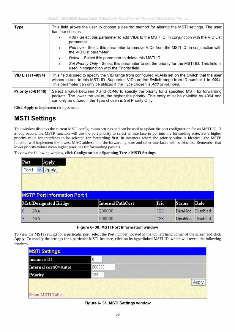
xStack® DES-3500 Series Layer 2 Stackable Fast Ethernet Managed Switch User Manual
56
Type This field allows the user to choose a desired method for altering the MSTI settings. The user has four choices.
• Add - Select this parameter to add VIDs to the MSTI ID, in conjunction with the VID List parameter.
• Remove - Select this parameter to remove VIDs from the MSTI ID, in conjunction with the VID List parameter.
• Delete - Select this parameter to delete this MSTI ID. • Set Priority Only - Select this parameter to set the priority for the MSTI ID. This field is
used in conjunction with the Priority field.
VID List (1-4094) This field is used to specify the VID range from configured VLANs set on the Switch that the user wishes to add to this MSTI ID. Supported VIDs on the Switch range from ID number 1 to 4094. This parameter can only be utilized if the Type chosen is Add or Remove.
Priority (0-61440) Select a value between 0 and 61440 to specify the priority for a specified MSTI for forwarding packets. The lower the value, the higher the priority. This entry must be divisible by 4094 and can only be utilized if the Type chosen is Set Priority Only.
Click Apply to implement changes made.
MSTI Settings This window displays the current MSTI configuration settings and can be used to update the port configuration for an MSTI ID. If a loop occurs, the MSTP function will use the port priority to select an interface to put into the forwarding state. Set a higher priority value for interfaces to be selected for forwarding first. In instances where the priority value is identical, the MSTP function will implement the lowest MAC address into the forwarding state and other interfaces will be blocked. Remember that lower priority values mean higher priorities for forwarding packets. To view the following window, click Configuration > Spanning Tree > MSTI Settings:
Figure 6- 30. MSTI Port Information window
To view the MSTI settings for a particular port, select the Port number, located in the top left hand corner of the screen and click Apply. To modify the settings for a particular MSTI Instance, click on its hyperlinked MSTI ID, which will reveal the following window.
Figure 6- 31. MSTI Settings window

xStack® DES-3500 Series Layer 2 Stackable Fast Ethernet Managed Switch User Manual
57
Parameter Description
Instance ID Displays the MSTI ID of the instance being configured. An entry of 0 in this field denotes the CIST (default MSTI).
Internal cost (0=Auto)
This parameter is set to represent the relative cost of forwarding packets to specified ports when an interface is selected within a STP instance. The default setting is 0 (auto). There are two options:
• 0 (auto) - Selecting this parameter for the internalCost will set quickest route automatically and optimally for an interface. The default value is derived from the media speed of the interface.
• value 1-2000000 - Selecting this parameter with a value in the range of 1-2000000 will set the quickest route when a loop occurs. A lower Internal cost represents a quicker transmission.
Priority Enter a value between 0 and 240 to set the priority for the port interface. A higher priority will designate the interface to forward packets first. A lower number denotes a higher priority.
Click Apply to implement changes made.
STP Instance Settings The following window displays MSTIs currently set on the Switch. To view the following table, click Configuration > Spanning Tree > STP Instance Settings:
Figure 6- 32. STP Instance Table window
The following information is displayed:
Parameter Description
Instance Type Displays the instance type(s) currently configured on the Switch. Each instance type is classified by a MSTI ID. CIST refers to the default MSTI configuration set on the Switch.
Instance Status Displays the current status of the corresponding MSTI ID
Instance Priority Displays the priority of the corresponding MSTI ID. The lowest priority will be the root bridge.
Click Apply to implement changes made. To acquire more detailed information on a particular STP Instance, click its hyperlinked Instance Type, which will display the following read-only window.

xStack® DES-3500 Series Layer 2 Stackable Fast Ethernet Managed Switch User Manual
58
Figure 6- 33. STP Instance Operational Status

xStack® DES-3500 Series Layer 2 Stackable Fast Ethernet Managed Switch User Manual
59
MSTP Port Information STP can be set up on a port per port basis. To view the following window click Configuration > Spanning Tree > MSTP Port Information:
Figure 6- 34. STP Port Settings window
In addition to setting Spanning Tree parameters for use on the switch level, the Switch allows for the configuration of groups of ports, each port-group of which will have its own spanning tree, and will require some of its own configuration settings. An STP Group will use the switch-level parameters entered above, with the addition of Port Priority and Port Cost. An STP Group spanning tree works in the same way as the switch-level spanning tree, but the root bridge concept is replaced with a root port concept. A root port is a port of the group that is elected based on port priority and port cost, to be the connection to the network for the group. Redundant links will be blocked, just as redundant links are blocked on the switch level. The STP on the switch level blocks redundant links between switches (and similar network devices). The port level STP will block redundant links within an STP Group. It is advisable to define an STP Group to correspond to a VLAN group of ports.

xStack® DES-3500 Series Layer 2 Stackable Fast Ethernet Managed Switch User Manual
60
NOTE: If you want to enable Forwarding BPDU on a per port basis, the following settings must first be in effect: 1. STP must be globally disabled and 2. Forwarding BPDU must be globally enabled. These are the default settings configurable in the STP Bridge Global Settings menu discussed previously.
The following STP Port Settings fields can be set:
Parameter Description
From/To A consecutive group of ports may be configured starting with the selected port.
External Cost This defines a metric that indicates the relative cost of forwarding packets to the specified port list. Port cost can be set automatically or as a metric value. The default value is 0 (auto). 0 (auto) - Setting 0 for the external cost will automatically set the speed for forwarding packets to the specified port(s) in the list for optimal efficiency. Default port cost: 100Mbps port = 200000. Gigabit port = 20000. value 1-200000000 - Define a value between 1 and 200000000 to determine the external cost. The lower the number, the greater the probability the port will be chosen to forward packets.
Hello Time The time interval between transmissions of configuration messages by the designated port, to other devices on the bridged LAN. The user may choose a time between 1 and 2 seconds. The default is 2 seconds. This field is only operable when the Switch is enabled for MSTP.
Migration Setting this parameter as "yes" will set the ports to send out BPDU packets to other bridges, requesting information on their STP setting If the Switch is configured for RSTP, the port will be capable to migrate from 802.1d STP to 802.1w RSTP. If the Switch is configured for MSTP, the port is capable of migrating from 802.1d STP to 802.1s MSTP. RSTP and MSTP can coexist with standard STP, however the benefits of RSTP and MSTP are not realized on a port where an 802.1d network connects to an 802.1w or 802.1s enabled network. Migration should be set as yes on ports connected to network stations or segments that are capable of being upgraded to 802.1w RSTP or 802.1s MSTP on all or some portion of the segment.
Edge Choosing the True parameter designates the port as an edge port. Edge ports cannot create loops, however an edge port can lose edge port status if a topology change creates a potential for a loop. An edge port normally should not receive BPDU packets. If a BPDU packet is received, it automatically loses edge port status. Choosing the False parameter indicates that the port does not have edge port status.
Restricted Role A Boolean value set by management. Two options are available for this parameter: Ture and False. If TRUE causes the Port not to be selected as Root Port for the CIST or any MSTI, even it has the best spanning tree priority vector. Such a Port will be selected as an Alternate Port after the Root Port has been selected. This parameter should be FALSE by default. If set, it can cause lack of spanning tree connectivity. It is set by a network administrator to prevent bridges external to a core region of the network influencing the spanning tree active topology, possibly because those bridges are not under the full control of the administrator.
Restricted Tcn A Boolean value set by management. Two options are available for this parameter: Ture and False. If TRUE causes the Port not to propagate received topology change notifications and topology changes to other Ports. This parameter should be FALSE by default. If set it can cause temporary loss of connectivity after changes in a spanning trees active topology as a result of persistent incorrectly learned station location information. It is set by a network administrator to prevent bridges external to a core region of the network, causing address flushing in that region, possibly because those bridges are not under the full control of the administrator or MAC_Operational for the attached LANs transitions frequently.
P2P Choosing the True parameter indicates a point-to-point (P2P) shared link. P2P ports are similar to edge ports, however they are restricted in that a P2P port must operate in full duplex. Like edge ports, P2P ports transition to a forwarding state rapidly thus benefiting from RSTP. A p2p value of False indicates that the port cannot have p2p status. Auto allows the port to have p2p status whenever possible and operate as if the p2p status were true. If the port cannot maintain this status, (for example if the port is forced to half-duplex operation) the p2p status changes to operate as if the p2p value were false. The default setting for this parameter is auto.
Forward BPDU Choosing True will allow the forwarding of BPDU packets in the specified ports from other network devices. This will go into effect only if STP is globally disabled AND Forwarding BPDU

xStack® DES-3500 Series Layer 2 Stackable Fast Ethernet Managed Switch User Manual
61
is globally enabled (See STP Bridge Global Settings above). hw_filtering is an option that is only required by some legacy chipsets, which cannot support per L2 protocol packet control. When the state is set to hw_filtering, if STP BPDU is received by this port, the port will be changed to BPDU hardware filtering mode such that all layer 2 control packets will be dropped by the hardware. The default setting False, does not forward BPDU packets when STP is disabled.
State This drop-down menu allows you to enable or disable STP for the selected group of ports. The default is Enabled.
Recover HW Filtering
When a port is in BPDU hardware filtering mode, it can be recovered by this option.
Click Apply to implement changes made.

xStack® DES-3500 Series Layer 2 Stackable Fast Ethernet Managed Switch User Manual
62
Loopback Detection This feature is used to temporarily shutdown a port on the Switch when a CTP (Configuration Testing Protocol) packet has been looped back to the switch. When the Switch detects CTP packets are received from a port or a VLAN, it signifies a loop on the network. The Switch will automatically block the port or the VLAN and send an alert to the administrator. The Loopback Detection port will restart (change to discarding state) when the Loopback Detection Recover Time times out. The Loopback Detection function can be implemented on a range of ports at a time. The user may enable or disable this function using the pull-down menu. To view this window click, Configuration > Loopback Detection.
Figure 6- 35 Loopback Detection Global Settings window

xStack® DES-3500 Series Layer 2 Stackable Fast Ethernet Managed Switch User Manual
63
The following parameters can be set:
Parameter Description
Loopback Detection Global Settings
Loopback Detection Status
Use the pull-down menu to enable or disable Loopback Detection globally on the Switch. The default is Disabled.
Interval (1-32767) Use the pull-down menu to set up the time interval (inseconds) at which the remote device transmits all the CTP packets to detect the loop-back event. The default value is 10, with a valid range of 1 to 32767,
Recover Time (0 or 60 – 1000000)
The time interval (in seconds) used by the Auto-Recovery mechanism to decide how long to check if the loop status is gone. The valid range is 60 to 1000000. Zero is a special value, which means to disable the auto-recovery mechanism. The default value is 60.
Mode Two modes are available: Port_based, VLAN_based. In port-based mode, the port will be disabled during the loop detection. In vlan-based mode, the port cannot porcess VLAN packets destined for ports involved in detecting the loop.
Loopback Detection Status Settings
From/To A consecutive group of ports may be configured starting with the selected port.
State Use the pull-down menu to enable or disable Loopback Detection on consecutive group of ports of the Switch. The default is Disabled.
Click Apply to implement changes made.
Forwarding Filtering Unicast Forwarding Open the Forwarding Filtering folder in the Configuration menu and click on the Unicast Forwarding link. This will open the Setup Static Unicast Forwarding Table, as shown below:
Figure 6- 36. Setup Static Unicast Forwarding Table window
To add or edit an entry, define the following parameters and then click Add/Modify:
Parameter Description
VLAN ID (VID) The VLAN ID number of the VLAN on which the above Unicast MAC address resides.
MAC Address The MAC address to which packets will be statically forwarded. This must be a unicast MAC address.
Allowed to Go Port Allows the selection of the port number on which the MAC address entered above resides.
Click Apply to implement the changes made. To delete an entry in the Static Unicast Forwarding Table, click the corresponding X under the Delete heading.

xStack® DES-3500 Series Layer 2 Stackable Fast Ethernet Managed Switch User Manual
64
Multicast Forwarding The following figure and table describe how to set up Multicast Forwarding on the Switch. To view this window click, Configuration > Forwarding Filtering > Multicast Forwarding:
Figure 6- 37. Static Multicast Forwarding Settings window
The Static Multicast Forwarding Settings window displays all of the entries made into the Switch's static multicast forwarding table. Click the Add button to open the Setup Static Multicast Forwarding Table window, as shown below:
Figure 6- 38. Setup Static Multicast Forwarding Table window
The following parameters can be set:
Parameter Description
VID The VLAN ID of the VLAN to which the corresponding MAC address belongs.
Multicast MAC Address
The MAC address of the static source of multicast packets. This must be a multicast MAC address.
Port Settings Allows the selection of ports that will be members of the static multicast group and ports either that are forbidden from joining dynamically, or that can join the multicast group dynamically, using GMRP. The options are: None - No restrictions on the port dynamically joining the multicast group. When None is chosen, the port will not be a member of the Static Multicast Group. Egress - The port is a static member of the multicast group.
Click Apply to implement the changes made. To delete an entry in the Static Multicast Forwarding Table, click the corresponding X under the Delete heading. Click the Show All Multicast Forwarding Entries link to return to the Static Multicast Forwarding Settings window.

xStack® DES-3500 Series Layer 2 Stackable Fast Ethernet Managed Switch User Manual
65
Multicast Port Filtering Mode The following figure and table describe how to set up multicast forwarding on the Switch. To view this window click, Configuration > Forwarding Filtering > Multicast Port Filtering Mode Setup.
Figure 6- 39. Multicast Port Filtering Mode Setup window
The following parameters can be set:
Parameter Description
From/To These two drop-down menus allow you to select a range of ports to which the filter settings will be applied.
Mode This drop-down menu allows you to select the action the Switch will take when it receives a multicast packet that is to be forwarded to one of the ports in the range specified above.

xStack® DES-3500 Series Layer 2 Stackable Fast Ethernet Managed Switch User Manual
66
• Forward All Groups - This will instruct the Switch to forward a multicast packet to all multicast groups residing within the range of ports specified above.
• Forward Unregistered Groups - This will instruct the Switch to forward a multicast packet whose destination is an unregistered multicast group residing within the range of ports specified above.
• Filter Unregistered Groups - This will instruct the Switch to filter any multicast packets whose destination is an unregistered multicast group residing within the range of ports specified above.
Click Apply to implement changes made.

xStack® DES-3500 Series Layer 2 Stackable Fast Ethernet Managed Switch User Manual
67
VLANs Understanding IEEE 802.1p Priority Priority tagging is a function defined by the IEEE 802.1p standard designed to provide a means of managing traffic on a network where many different types of data may be transmitted simultaneously. It is intended to alleviate problems associated with the delivery of time critical data over congested networks. The quality of applications that are dependent on such time critical data, such as video conferencing, can be severely and adversely affected by even very small delays in transmission. Network devices that are in compliance with the IEEE 802.1p standard have the ability to recognize the priority level of data packets. These devices can also assign a priority label or tag to packets. Compliant devices can also strip priority tags from packets. This priority tag determines the packet's degree of expeditiousness and determines the queue to which it will be assigned. Priority tags are given values from 0 to 7 with 0 being assigned to the lowest priority data and 7 assigned to the highest. The highest priority tag 7 is generally only used for data associated with video or audio applications, which are sensitive to even slight delays, or for data from specified end users whose data transmissions warrant special consideration. The Switch allows you to further tailor how priority tagged data packets are handled on your network. Using queues to manage priority tagged data allows you to specify its relative priority to suit the needs of your network. There may be circumstances where it would be advantageous to group two or more differently tagged packets into the same queue. Generally, however, it is rec-ommended that the highest priority queue, Queue 1, be reserved for data packets with a priority value of 7. Packets that have not been given any priority value are placed in Queue 0 and thus given the lowest priority for delivery. A weighted round robin system is employed on the Switch to determine the rate at which the queues are emptied of packets. The ratio used for clearing the queues is 4:1. This means that the highest priority queue, Queue 1, will clear 4 packets for every 1 packet cleared from Queue 0. Remember, the priority queue settings on the Switch are for all ports, and all devices connected to the Switch will be affected. This priority queuing system will be especially beneficial if your network employs switches with the capability of assigning priority tags.
VLAN Description A Virtual Local Area Network (VLAN) is a network topology configured according to a logical scheme rather than the physical layout. VLANs can be used to combine any collection of LAN segments into an autonomous user group that appears as a single LAN. VLANs also logically segment the network into different broadcast domains so that packets are forwarded only between ports within the VLAN. Typically, a VLAN corresponds to a particular subnet, although not necessarily. VLANs can enhance performance by conserving bandwidth, and improve security by limiting traffic to specific domains. A VLAN is a collection of end nodes grouped by logic instead of physical location. End nodes that frequently communicate with each other are assigned to the same VLAN, regardless of where they are physically on the network. Logically, a VLAN can be equated to a broadcast domain, because broadcast packets are forwarded to only members of the VLAN on which the broadcast was initiated.
Notes about VLANs on the xStack® DES-3500 Series switches No matter what basis is used to uniquely identify end nodes and assign these nodes VLAN membership, packets cannot cross VLANs without a network device performing a routing function between the VLANs. The DES-3500 Series switches supports IEEE 802.1Q VLANs and Port-Based VLANs. The port untagging function can be used to remove the 802.1Q tag from packet headers to maintain compatibility with devices that are tag-unaware. The Switch's default is to assign all ports to a single 802.1Q VLAN named "default." The "default" VLAN has a VID = 1. The member ports of Port-based VLANs may overlap, if desired.
IEEE 802.1Q VLANs Some relevant terms:
• Tagging - The act of putting 802.1Q VLAN information into the header of a packet. • Untagging - The act of stripping 802.1Q VLAN information out of the packet header. • Ingress port - A port on a switch where packets are flowing into the Switch and VLAN decisions must
be made. • Egress port - A port on a switch where packets are flowing out of the Switch, either to another switch
or to an end station, and tagging decisions must be made.

xStack® DES-3500 Series Layer 2 Stackable Fast Ethernet Managed Switch User Manual
68
IEEE 802.1Q (tagged) VLANs are implemented on the Switch. 802.1Q VLANs require tagging, which enables them to span the entire network (assuming all switches on the network are IEEE 802.1Q-compliant). VLANs allow a network to be segmented in order to reduce the size of broadcast domains. All packets entering a VLAN will only be forwarded to the stations (over IEEE 802.1Q enabled switches) that are members of that VLAN, and this includes broadcast, multicast and unicast packets from unknown sources. VLANs can also provide a level of security to your network. IEEE 802.1Q VLANs will only deliver packets between stations that are members of the VLAN. Any port can be configured as either tagging or untagging. The untagging feature of IEEE 802.1Q VLANs allows VLANs to work with legacy switches that don't recognize VLAN tags in packet headers. The tagging feature allows VLANs to span multiple 802.1Q-compliant switches through a single physical connection and allows Spanning Tree to be enabled on all ports and work normally. The IEEE 802.1Q standard restricts the forwarding of untagged packets to the VLAN the receiving port is a member of. The main characteristics of IEEE 802.1Q are as follows:
• Assigns packets to VLANs by filtering. • Assumes the presence of a single global spanning tree. • Uses an explicit tagging scheme with one-level tagging. • 802.1Q VLAN Packet Forwarding • Packet forwarding decisions are made based upon the following three types of rules: • Ingress rules - rules relevant to the classification of received frames belonging to a VLAN. • Forwarding rules between ports - decides whether to filter or forward the packet. • Egress rules - determines if the packet must be sent tagged or untagged.
Figure 6- 40. IEEE 802.1Q Packet Forwarding

xStack® DES-3500 Series Layer 2 Stackable Fast Ethernet Managed Switch User Manual
69
802.1Q VLAN Tags The figure below shows the 802.1Q VLAN tag. There are four additional octets inserted after the source MAC address. Their presence is indicated by a value of 0x8100 in the EtherType field. When a packet's EtherType field is equal to 0x8100, the packet carries the IEEE 802.1Q/802.1p tag. The tag is contained in the following two octets and consists of 3 bits of user priority, 1 bit of Canonical Format Identifier (CFI - used for encapsulating Token Ring packets so they can be carried across Ethernet backbones), and 12 bits of VLAN ID (VID). The 3 bits of user priority are used by 802.1p. The VID is the VLAN identifier and is used by the 802.1Q standard. Because the VID is 12 bits long, 4094 unique VLANs can be identified. The tag is inserted into the packet header making the entire packet longer by 4 octets. All of the information originally contained in the packet is retained.
Figure 6- 41. IEEE 802.1Q Tag
The EtherType and VLAN ID are inserted after the MAC source address, but before the original EtherType/Length or Logical Link Control. Because the packet is now a bit longer than it was originally, the Cyclic Redundancy Check (CRC) must be recalculated.
Figure 6- 42. Adding an IEEE 802.1Q Tag
Port VLAN ID Packets that are tagged (are carrying the 802.1Q VID information) can be transmitted from one 802.1Q compliant network device to another with the VLAN information intact. This allows 802.1Q VLANs to span network devices (and indeed, the entire network, if all network devices are 802.1Q compliant).

xStack® DES-3500 Series Layer 2 Stackable Fast Ethernet Managed Switch User Manual
70
Unfortunately, not all network devices are 802.1Q compliant. These devices are referred to as tag-unaware. 802.1Q devices are referred to as tag-aware. Prior to the adoption of 802.1Q VLANs, port-based and MAC-based VLANs were in common use. These VLANs relied upon a Port VLAN ID (PVID) to forward packets. A packet received on a given port would be assigned that port's PVID and then be forwarded to the port that corresponded to the packet's destination address (found in the Switch's forwarding table). If the PVID of the port that received the packet is different from the PVID of the port that is to transmit the packet, the Switch will drop the packet. Within the Switch, different PVIDs mean different VLANs (remember that two VLANs cannot communicate without an external router). So, VLAN identification based upon the PVIDs cannot create VLANs that extend outside a given switch (or switch stack). Every physical port on a switch has a PVID. 802.1Q ports are also assigned a PVID, for use within the Switch. If no VLANs are defined on the Switch, all ports are then assigned to a default VLAN with a PVID equal to 1. Untagged packets are assigned the PVID of the port on which they were received. Forwarding decisions are based upon this PVID, in so far as VLANs are concerned. Tagged packets are forwarded according to the VID contained within the tag. Tagged packets are also assigned a PVID, but the PVID is not used to make packet-forwarding decisions, the VID is. Tag-aware switches must keep a table to relate PVIDs within the Switch to VIDs on the network. The Switch will compare the VID of a packet to be transmitted to the VID of the port that is to transmit the packet. If the two VIDs are different, the Switch will drop the packet. Because of the existence of the PVID for untagged packets and the VID for tagged packets, tag-aware and tag-unaware network devices can coexist on the same network. A switch port can have only one PVID, but can have as many VIDs as the Switch has memory in its VLAN table to store them. Because some devices on a network may be tag-unaware, a decision must be made at each port on a tag-aware device before packets are transmitted - should the packet to be transmitted have a tag or not? If the transmitting port is connected to a tag-unaware device, the packet should be untagged. If the transmitting port is connected to a tag-aware device, the packet should be tagged.
Tagging and Untagging Every port on an 802.1Q compliant switch can be configured as tagging or untagging. Ports with tagging enabled will put the VID number, priority and other VLAN information into the header of all packets that flow into and out of it. If a packet has previously been tagged, the port will not alter the packet, thus keeping the VLAN information intact. Other 802.1Q compliant devices on the network to make packet-forwarding decisions can then use the VLAN information in the tag. Ports with untagging enabled will strip the 802.1Q tag from all packets that flow into and out of those ports. If the packet doesn't have an 802.1Q VLAN tag, the port will not alter the packet. Thus, all packets received by and forwarded by an untagging port will have no 802.1Q VLAN information. (Remember that the PVID is only used internally within the Switch). Untagging is used to send packets from an 802.1Q-compliant network device to a non-compliant network device.
Ingress Filtering A port on a switch where packets are flowing into the Switch and VLAN decisions must be made is referred to as an ingress port. If ingress filtering is enabled for a port, the Switch will examine the VLAN information in the packet header (if present) and decide whether or not to forward the packet. If the packet is tagged with VLAN information, the ingress port will first determine if the ingress port itself is a member of the tagged VLAN. If it is not, the packet will be dropped. If the ingress port is a member of the 802.1Q VLAN, the Switch then determines if the destination port is a member of the 802.1Q VLAN. If it is not, the packet is dropped. If the destination port is a member of the 802.1Q VLAN, the packet is forwarded and the destination port transmits it to its attached network segment. If the packet is not tagged with VLAN information, the ingress port will tag the packet with its own PVID as a VID (if the port is a tagging port). The switch then determines if the destination port is a member of the same VLAN (has the same VID) as the ingress port. If it does not, the packet is dropped. If it has the same VID, the packet is forwarded and the destination port transmits it on its attached network segment. This process is referred to as ingress filtering and is used to conserve bandwidth within the Switch by dropping packets that are not on the same VLAN as the ingress port at the point of reception. This eliminates the subsequent processing of packets that will just be dropped by the destination port.
Default VLANs The Switch initially configures one VLAN, VID = 1, called "default." The factory default setting assigns all ports on the Switch to the "default." As new VLANs are configured in Port-based mode, their respective member ports are removed from the "default." Packets cannot cross VLANs. If a member of one VLAN wants to connect to another VLAN, the link must be through an external router.

xStack® DES-3500 Series Layer 2 Stackable Fast Ethernet Managed Switch User Manual
71
NOTE: If no VLANs are configured on the Switch, then all packets will be forwarded to any desti-nation port. Packets with unknown source addresses will be flooded to all ports. Broadcast and multicast packets will also be flooded to all ports.
An example is presented below:
VLAN Name VID Switch Ports
System (default) 1 5, 6, 7, 8, 21, 22, 23, 24
Engineering 2 9, 10, 11, 12
Marketing 3 13, 14, 15, 16
Finance 4 17, 18, 19, 20
Sales 5 1, 2, 3, 4
Table 6- 2. VLAN Example - Assigned Ports
Port-based VLANs Port-based VLANs limit traffic that flows into and out of switch ports. Thus, all devices connected to a port are members of the VLAN(s) the port belongs to, whether there is a single computer directly connected to a switch, or an entire department. On port-based VLANs, NICs do not need to be able to identify 802.1Q tags in packet headers. NICs send and receive normal Ethernet packets. If the packet's destination lies on the same segment, communications take place using normal Ethernet protocols. Even though this is always the case, when the destination for a packet lies on another switch port, VLAN considerations come into play to decide if the packet gets dropped by the Switch or delivered.
VLAN Segmentation Take for example a packet that is transmitted by a machine on Port 1 that is a member of VLAN 2. If the destination lies on another port (found through a normal forwarding table lookup), the Switch then looks to see if the other port (Port 10) is a member of VLAN 2 (and can therefore receive VLAN 2 packets). If Port 10 is not a member of VLAN 2, then the packet will be dropped by the Switch and will not reach its destination. If Port 10 is a member of VLAN 2, the packet will go through. This selective forwarding feature based on VLAN criteria is how VLANs segment networks. The key point being that Port 1 will only transmit on VLAN 2.

xStack® DES-3500 Series Layer 2 Stackable Fast Ethernet Managed Switch User Manual
72
Asymmetric VLANs The xStack® DES-3500 Switch Series has the capability to create and utilize Asymmetric VLANs on the Switch. Asymmetric VLANs allow devices to transmit packets on one VLAN and receive it on another VLAN. This configuration is accomplished through the use of three functions: enabling Asymmetric VLANs, VLAN creation, and GVRP configuration. Consider the example below.
Figure 6- 43. Asymmetric VLANs Example
In order to accomplish an Asymmetric VLAN configuration, the user must do a three part configuration: 1. Enable Asymmetric VLANs using the Advanced Settings window located in the Configuration folder. Overlapping
VLANs cannot be configured unless this function is enabled. 2. Configure the VLAN settings. The example above uses ports 1-8 to hold the devices to be shared on the network, such as
shared servers and shared printers. Therefore, this group of ports is to be included for all VLANs. VLAN V2 is then configured to include ports 1-8 (shared VLAN ports) and the set of ports to be separated from the other subsetted VLANs (ports 9-16). VLAN V3 is then configured to include ports 1-8 (shared ports) and the set of ports to be separated from the other subsetted VLANs (17-24). Therefore we have two VLANs who both share ports and have ports that are separated from each other and thus cannot communicate with each other.
3. Configure the PVID settings for the Switch through the GVRP function located in the VLANs folder. The user is to set the shared set of ports as PVID 1, the other separated groups of ports as PVID 2 and PVID 3.
After completing the previous configuration, the user is now able to share the network resources set on the shared group of ports (nominated as PVID 1), with both smaller subsets of VLANs (nominated PVID 2 and PVID 3). Yet, VLAN V1 and VLAN V2 are incapable of sharing information with each other and the Overlapping VLAN configuration has been successfully created.

xStack® DES-3500 Series Layer 2 Stackable Fast Ethernet Managed Switch User Manual
73
VLAN and Trunk Groups
The members of a trunk group have the same VLAN setting. Any VLAN setting on the members of a trunk group will apply to the other member ports.
NOTE: In order to use VLAN segmentation in conjunction with port trunk groups, you can first set the port trunk group(s), and then you may configure VLAN settings. If you wish to change the port trunk grouping with VLANs already in place, you will not need to reconfigure the VLAN settings after changing the port trunk group settings. VLAN settings will automatically change in conjunction with the change of the port trunk group settings.
Static VLAN Entry To view the Static VLAN Entries on the Switch click, Configuration > VLAN > Static VLAN Entry which will open the following window:
Figure 6- 44. Current 802.1Q Static VLANs Entries window
The 802.1Q Static VLANs window lists all previously configured VLANs by VLAN ID and VLAN Name. To delete an existing 802.1Q VLAN, click the corresponding X button under the Delete heading. To create a new 802.1Q VLAN, click the Add button in the 802.1Q Static VLANs Entries window. A new window will appear, as shown below, to configure the port settings and to assign a unique name and number to the new VLAN. See the table below for a description of the parameters in the new window.

xStack® DES-3500 Series Layer 2 Stackable Fast Ethernet Managed Switch User Manual
74
Figure 6- 45. 802.1Q Static VLAN window - Add
To return to the Current 802.1Q Static VLANs Entries window, click the Show All Static VLAN Entries link. To change an existing 802.1Q VLAN entry, click the Modify button of the corresponding entry you wish to modify. A new menu will appear to configure the port settings and to assign a unique name and number to the new VLAN. See the table below for a description of the parameters in the new menu. To configure a VLAN by its VID List, click the Add or configure VLAN by VID List button on the Current 802.1Q Static VLANs Entries table, the following window will appear.
Figure 6- 46. 802.1Q Static VLAN window - Add or configure VLAN by VID List

xStack® DES-3500 Series Layer 2 Stackable Fast Ethernet Managed Switch User Manual
75
NOTE: The Switch supports up to 255 static VLAN entries.
Figure 6- 47. 802.1Q Static VLAN window - Modify
The following fields can then be set in either the Add or Modify 802.1Q Static VLANs windows:
Parameter Description
VID (VLAN ID) Allows the entry of a VLAN ID in the Add window, or displays the VLAN ID of an existing VLAN in the Modify window. VLANs can be identified by either the VID or the VLAN name.
VLAN Name Allows the entry of a name for the new VLAN in the Add window, or for editing the VLAN name in the Modify window.
Advertisement Enabling this function will allow the Switch to send out GVRP packets to outside sources, notifying that they may join the existing VLAN.
Port Settings Allows an individual port to be specified as member of a VLAN.
Tag Specifies the port as either 802.1Q tagging or 802.1Q untagged. Checking the box will desig-nate the port as Tagged.
None Allows an individual port to be specified as a non-VLAN member.
Egress Select this to specify the port as a static member of the VLAN. Egress member ports are ports that will be transmitting traffic for the VLAN. These ports can be either tagged or untagged.
Forbidden Select this to specify the port as not being a member of the VLAN and that the port is forbidden from becoming a member of the VLAN dynamically.
Click Apply to implement changes made.

xStack® DES-3500 Series Layer 2 Stackable Fast Ethernet Managed Switch User Manual
76
GVRP Setting
Figure 6- 48. 802.1Q Port Settings window
The following fields can be set:
Parameter Description
From/To These two fields allow you to specify the range of ports that will be included in the Port-based VLAN that you are creating using the 802.1Q Port Settings window.
PVID The read-only field in the 802.1Q Port Table shows the current PVID assignment for each port, which may be manually assigned to a VLAN when created in the 802.1Q Port Settings table. The Switch's default is to assign all ports to the default VLAN with a VID of 1.The PVID is used by the port to tag outgoing, untagged packets, and to make filtering decisions about incoming packets. If the port is specified to accept only tagged frames - as tagging, and an untagged packet is forwarded to the port for transmission, the port will add an 802.1Q tag using the PVID to write the VID in the tag. When the packet arrives at its destination, the receiving device will use the PVID to make VLAN forwarding decisions. If the port receives a packet, and Ingress filtering is enabled, the port will compare the VID of the incoming packet to its PVID. If the two are unequal, the port will drop the packet. If the two are equal, the port will receive the packet.
GVRP The Group VLAN Registration Protocol (GVRP) enables the port to dynamically become a member of a VLAN. GVRP is Disabled by default.
Ingress This field can be toggled using the space bar between Enabled and Disabled. Enabled enables the port to compare the VID tag of an incoming packet with the PVID number assigned to the port. If the two are different, the port filters (drops) the packet. Disabled disables ingress fil-tering. Ingress Checking is Disabled by default.
Acceptable Frame Type
This field denotes the type of frame that will be accepted by the port. The user may choose between Tagged Only, which means only VLAN tagged frames will be accepted, and Admit_All, which mean both tagged and untagged frames will be accepted. Admit_All is enabled by default.
The 802.1Q Port Settings window, shown below, allows you to determine whether the Switch will share its VLAN configuration information with other GARP VLAN Registration Protocol (GVRP) enabled switches. In addition, Ingress Checking can be used to limit traffic by filtering incoming packets whose PVID does not match the PVID of the port. Results can be seen in the table under the configuration settings, as seen below. To view this window click, Configuration > VLANs > GVRP Setting.

xStack® DES-3500 Series Layer 2 Stackable Fast Ethernet Managed Switch User Manual
77
Click Apply to implement changes made.
Traffic Control On a computer network, packets such as Multicast packets and Broadcast packets continually flood the network as normal procedure. At times, this traffic may increase do to a malicious endstation on the network or a malfunctioning device, such as a faulty network card. Thus, switch throughput problems will arise and consequently affect the overall performance of the switch network. To help rectify this packet storm, the Switch will monitor and control the situation. The packet storm is monitored to determine if too many packets are flooding the network, based on the threshold level provided by the user. Once a packet storm has been detected, the Switch will drop packets coming into the Switch until the storm has subsided. This method can be utilized by selecting the Drop option of the Action field in the window below. The Switch will also scan and monitor packets coming into the Switch by monitoring the Switch’s chip counter. This method is only viable for Broadcast and Multicast storms because the chip only has counters for these two types of packets. Once a storm has been detected (that is, once the packet threshold set below has been exceeded), the Switch will shutdown the port to all incoming traffic with the exception of STP BPDU packets, for a time period specified using the CountDown field. If this field times out and the packet storm continues, the port will be placed in a Shutdown Forever mode which will produce a warning message to be sent to the Trap Receiver. Once in Shutdown Forever mode, one method of recovering this port is to manually recoup it using the Port Configuration window in the Configuration folder, and selecting the disabled port and returning it to an Enabled status. Otherwise, the Shutdown Forever mode will be Auto-Recovery after 5 mins. To utilize this method of Storm Control, choose the Shutdown option of the Action field in the window below. To view this window click, Configuration > Traffic Control.
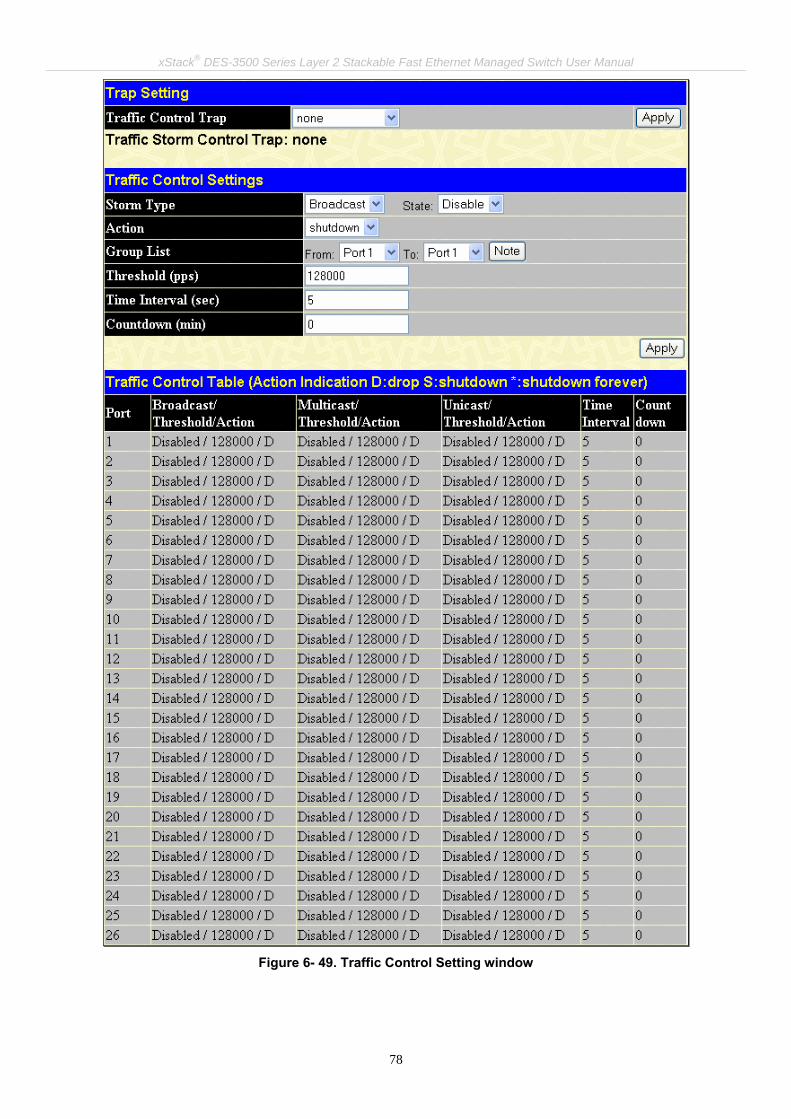
xStack® DES-3500 Series Layer 2 Stackable Fast Ethernet Managed Switch User Manual
78
Figure 6- 49. Traffic Control Setting window

xStack® DES-3500 Series Layer 2 Stackable Fast Ethernet Managed Switch User Manual
79
Use the Traffic Control Setting window to enable or disable storm control and adjust the threshold for multicast and broadcast storms, as well as Unicast (Destination Look Up Failure). Traffic control settings are applied to individual Switch modules. To view the following window, click Configuration > Traffic Control: The user may set the following parameters:
Parameter Description
Trap Setting
Traffic Control Trap
Enable sending of Storm Trap messages when the type of action taken by the Traffic Control function in handling a Traffic Storm is one of the following: None – Will send no Storm trap warning messages regardless of action taken by the Traffic Control mechanism. Storm Occurred – Will send Storm Trap warning messages upon the occurrence of a Traffic Storm only. Storm Cleared – Will send Storm Trap messages when a Traffic Storm has been cleared by the Switch only. Both – Will send Storm Trap messages when a Traffic Storm has been both detected and cleared by the Switch. This function cannot be implemented in the Hardware mode. (When Drop is chosen in the Action field.
Traffic Control Settings
Storm Type Select the type of Storm Type to detect, either Broadcast Multicast or Unicast. Once selected , use the pull-down menu to enable or disable this storm detection.
Action Select the method of traffic Control from the pull down menu. The choices are: shutdown – Utilizes the Switch’s software Traffic Control mechanism to determine the Packet Storm occurring. Once detected, the port will deny all incoming traffic to the port except STP BPDU packets, which are essential in keeping the Spanning Tree operational on the Switch. If the countdown timer has expired and yet the Packet Storm continues, the port will be placed in Shutdown Forever mode and is no longer operational until the user manually resets the port using the config ports enable command or waits for 5 mins to let the Shutdown Forever mode enter Auto-Recovery. Choosing this option obligates the user to configure the Interval setting as well, which will provide packet count samplings from the Switch’s chip to determine if a Packet Storm is occurring. drop – Utilizes the hardware Traffic Control mechanism, which means the Switch’s hardware will determine the Packet Storm based on the Threshold value stated and drop packets until the issue is resolved.
Group List Select the ports to be manually recovered from the Shutdown state.
Threshold Specifies the maximum number of packets per second that will trigger the Traffic Control function to commence. The configurable threshold range is from 0-255000 with a default setting of 128000.
Time Interval The Interval will set the time between Multicast and Broadcast packet counts sent from the Switch’s chip to the Traffic Control function. These packet counts are the determining factor in deciding when incoming packets exceed the Threshold value. The Interval may be set between 5 and 30 seconds with the default setting of 5 seconds.
Count Down The Count Down timer is set to determine the amount of time, in minutes, that the Switch will wait before shutting down the port that is experiencing a traffic storm. This parameter is only useful for ports configured as Shutdown in their Action field and therefore will not operate for Hardware based Traffic Control implementations. The possible time settings for this field are 0, 5-30 minutes. 0 is the default setting for this field and 0 will denote that the port will immediately shutdown.
Click Apply to implement the settings made.
NOTE: Traffic Control cannot be implemented on ports that are set for Link Aggregation (Port Trunking).

xStack® DES-3500 Series Layer 2 Stackable Fast Ethernet Managed Switch User Manual
80
NOTE: Ports that are in the Shutdown forever mode will be seen as Discarding in Spanning Tree windows and implementations though these ports will still be forwarding BPDUs to the Switch’s CPU.
NOTE: Ports that are in Shutdown Forever mode will be seen as link down in all windows and screens until the user recovers these ports or waits for 5 mins to let the Shutdown Forever mode enter Auto-Recovery.
NOTE: When configuring the traffic storm settings, remember that when it is configured for shutdown, the Group List will refer to individual ports. Yet, when the traffic control is configured for drop, the group list refers to groups of ports. (Ex – 1 refers to ports 1 through 8, 2 refers to ports 9-16…)
The group list settings for drop are as follows: Group 1 - Inclusive for ports 1-8. Group 2 - Inclusive for ports 9-16. Group 3 - Inclusive for ports 17-24. Group 4 - Inclusive for ports 9-16 (DES-3550). Inclusive for Gigabit port 25 (DES-3526). Group 5 - Inclusive for ports 33-40 (DES-3550). Inclusive for Gigabit port 26 (DES-3526). Group 6 - Inclusive for ports 41-48 (DES-3550 only). Group 7 - Inclusive for Gigabit port 49 (DES-3550 only). Group 8 - Inclusive for Gigabit port 50 (DES-3550 only).

xStack® DES-3500 Series Layer 2 Stackable Fast Ethernet Managed Switch User Manual
81
Port Security
Figure 6- 50. Port Security Settings window
The following parameters can be set:
Parameter Description
Port Security Trap/Log State Use the pull-down menu the enable or disable Port Security Trap/Log messages to be sent to
the Switch’s log file and to the SNMP manager.
Port Security Settings From/To A consecutive group of ports may be configured starting with the selected port.
Admin State This pull-down menu allows you to enable or disable Port Security (locked MAC address table for the selected ports).
Max. Learning Addr. (0-64)
The number of MAC addresses that will be in the MAC address-forwarding table for the selected switch and group of ports.
Lock Address Mode
This pull-down menu allows you to select how the MAC address table locking will be implemented on the Switch, for the selected group of ports. The options are:
• Permanent – The locked addresses will not age out after the aging timer expires. • Delete OnTimeout – The locked addresses will age out after the aging timer expires. • Delete On Reset – The locked addresses will not age out until the Switch has been
reset.
Click Apply to implement changes made.
A given port's (or a range of ports') dynamic MAC address learning can be locked such that the current source MAC addresses entered into the MAC address forwarding table can not be changed once the port lock is enabled. Using the Admin State pull-down menu to Enabled, and clicking Apply can lock the port. Port Security is a security feature that prevents unauthorized computers (with source MAC addresses) unknown to the Switch prior to locking the port (or ports) from connecting to the Switch's locked ports and gaining access to the network. To view this window click, Configuration > Port Security.

xStack® DES-3500 Series Layer 2 Stackable Fast Ethernet Managed Switch User Manual
82
QoS The DES-3500 Series switches supports 802.1p priority queuing Quality of Service. The following section discusses the implementation of QoS (Quality of Service) and benefits of using 802.1p priority queuing.
Advantages of QoS QoS is an implementation of the IEEE 802.1p standard that allows network administrators a method of reserving bandwidth for important functions that require a large bandwidth or have a high priority, such as VoIP (voice-over Internet Protocol), web browsing applications, file server applications or video conferencing. Not only can a larger bandwidth be created, but other less critical traffic can be limited, so excessive bandwidth can be saved. The Switch has separate hardware queues on every physical port to which packets from various applications can be mapped to, and, in turn prioritized. View the following map to see how the DES-3500 Series switches implements 802.1P priority queuing.
Figure 6- 51. Mapping QoS on the Switch
The picture above shows the default priority setting for the Switch. Class-3 has the highest priority of the four priority queues on the Switch. In order to implement QoS, the user is required to instruct the Switch to examine the header of a packet to see if it has the proper identifying tag tagged. Then the user may forward these tagged packets to designated queues on the Switch where they will be emptied, based on priority. For example, lets say a user wishes to have a video conference between two remotely set computers. The administrator can add priority tags to the video packets being sent out, utilizing the Access Profile commands. Then, on the receiving end, the administrator instructs the Switch to examine packets for this tag, acquires the tagged packets and maps them to a class queue on the Switch. Then in turn, the administrator will set a priority for this queue so that will be emptied before any other packet is forwarded. This results in the end user receiving all packets sent as quickly as possible, thus prioritizing the queue and allowing for an uninterrupted stream of packets, which optimizes the use of bandwidth available for the video conference.

xStack® DES-3500 Series Layer 2 Stackable Fast Ethernet Managed Switch User Manual
83
Understanding QoS
The Switch has four priority queues. These priority queues are labeled as 3, the high queue to 0, the lowest queue. The eight priority tags, specified in IEEE 802.1p are mapped to the Switch's priority tags as follows:
• Priority 0 is assigned to the Switch's Q1 queue.
• Priority 1 is assigned to the Switch's Q0 queue.
• Priority 2 is assigned to the Switch's Q0 queue.
• Priority 3 is assigned to the Switch's Q1 queue.
• Priority 4 is assigned to the Switch's Q2 queue.
• Priority 5 is assigned to the Switch's Q2 queue.
• Priority 6 is assigned to the Switch's Q3 queue.
• Priority 7 is assigned to the Switch's Q3 queue.
For strict priority-based scheduling, any packets residing in the higher priority queues are transmitted first. Multiple strict priority queues empty based on their priority tags. Only when these queues are empty, are packets of lower priority transmitted. For weighted round robin queuing, the number of packets sent from each priority queue depends upon the assigned weight. For a configuration of 8 CoS queues, A~H with their respective weight value: 8~1, the packets are sent in the following sequence: A1, B1, C1, D1, E1, F1, G1, H1, A2, B2, C2, D2, E2, F2, G2, A3, B3, C3, D3, E3, F3, A4, B4, C4, D4, E4, A5, B5, C5, D5, A6, B6, C6, A7, B7, A8, A1, B1, C1, D1, E1, F1, G1, H1. For weighted round robin queuing, if each CoS queue has the same weight value, then each CoS queue has an equal opportunity to send packets just like round robin queuing. For weighted round-robin queuing, if the weight for a CoS is set to 0, then it will continue processing the packets from this CoS until there are no more packets for this CoS. The other CoS queues that have been given a nonzero value, and depending upon the weight, will follow a common weighted round-robin scheme. Remember that the DES-3500 Series switches has four priority queues (and four Classes of Service) for each port on the Switch.

xStack® DES-3500 Series Layer 2 Stackable Fast Ethernet Managed Switch User Manual
84
Port Bandwidth The bandwidth control settings are used to place a ceiling on the transmitting and receiving data rates for any selected port. Click Configuration > QoS > Port Bandwidth, to view the window shown below.
Figure 6- 52. Bandwidth Settings window
The following parameters can be set or are displayed:
Parameter Description
From/To A consecutive group of ports may be configured starting with the selected port. Type This drop-down menu allows you to select between RX (receive), TX (transmit), and Both. This
setting will determine whether the bandwidth ceiling is applied to receiving, transmitting, or both

xStack® DES-3500 Series Layer 2 Stackable Fast Ethernet Managed Switch User Manual
85
receiving and transmitting packets. No Limit This drop-down menu allows you to specify that the selected port will have no bandwidth limit.
Enabled disables the limit. Rate This field allows you to enter the data rate, in Mbit/s, that will be the limit for the selected port.
Effective Rx rate Specifies the limitation of the received data rate.
Effective Tx rate Specifies the limitation of the transmitted data rate.
Click Apply to set the bandwidth control for the selected ports. Results of configured Bandwidth Settings will be displayed in the Port Bandwidth Table.
Scheduling Changing the output scheduling used for the hardware queues in the Switch can customize QoS. As with any changes to QoS implementation, careful consideration should be given to how network traffic in lower priority queues is affected. Changes in scheduling may result in unacceptable levels of packet loss or significant transmission delay. If you choose to customize this setting, it is important to monitor network performance, especially during peak demand, as bottlenecks can quickly develop if the QoS settings are not suitable. Click, Configuration > QoS > Scheduling to view the window shown below.
Figure 6- 53. QoS Output Scheduling window
You may assign the following values to the QoS classes to set the scheduling.
Parameter Description
Max. Packets (0-255) Specifies the maximum number of packets the above specified hardware priority queue would be allowed to transmit before allowing the next lowest priority queue to transmit its packets. A value between 0 and 255 can be specified.
Max. Latency (0-255) Specifies the maximum amount of time the above specified hardware priority queue will be allowed to transmit packets before allowing the next lowest hardware priority queue to begin transmitting its packets. A value between 0 and 255 can be specified - with this value multiplied by 16 ms to arrive at the total allowed time for the queue to transmit packets. For example, a value of 3 specifies 3 X 16 = 48 ms. The queue will continue transmitting the last packet until it is finished when the max latency timer expires.
Click Apply to implement changes made.
NOTE: The settings you assign to the queues, numbers 0-7, represent the IEEE 802.1p priority tag number. Do not confuse these settings with port numbers.
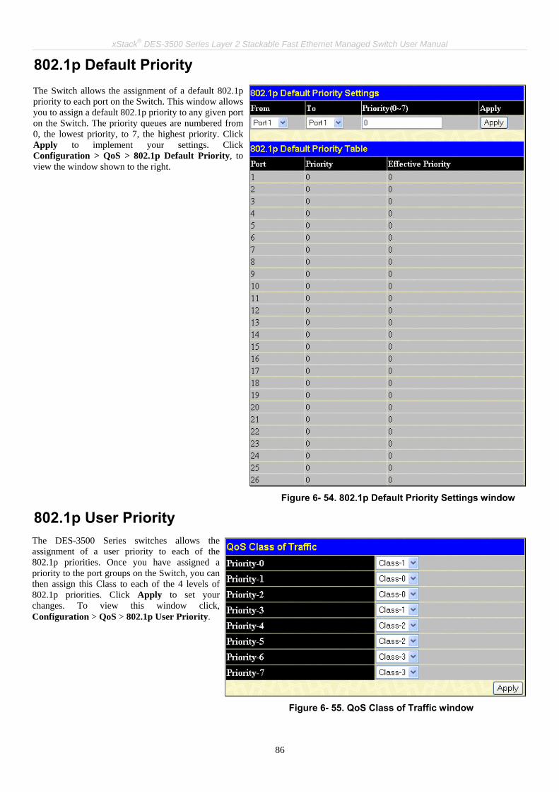
xStack® DES-3500 Series Layer 2 Stackable Fast Ethernet Managed Switch User Manual
86
802.1p Default Priority
Figure 6- 54. 802.1p Default Priority Settings window
802.1p User Priority
Figure 6- 55. QoS Class of Traffic window
The Switch allows the assignment of a default 802.1p priority to each port on the Switch. This window allows you to assign a default 802.1p priority to any given port on the Switch. The priority queues are numbered from 0, the lowest priority, to 7, the highest priority. Click Apply to implement your settings. Click Configuration > QoS > 802.1p Default Priority, to view the window shown to the right.
The DES-3500 Series switches allows the assignment of a user priority to each of the 802.1p priorities. Once you have assigned a priority to the port groups on the Switch, you can then assign this Class to each of the 4 levels of 802.1p priorities. Click Apply to set your changes. To view this window click, Configuration > QoS > 802.1p User Priority.

xStack® DES-3500 Series Layer 2 Stackable Fast Ethernet Managed Switch User Manual
87
Traffic Segmentation Traffic segmentation is used to limit traffic flow from a single port to a group of ports on either a single switch (in standalone mode) or a group of ports on another switch in a switch stack (Single IP). This method of segmenting the flow of traffic is similar to using VLANs to limit traffic, but is more restrictive. It provides a method of directing traffic that does not increase the overhead of the Master switch CPU. To view this window click, Configuration >QoS > Traffic Segmentation.
Figure 6- 56. Traffic Segmentation Setting window
This page allows you to determine which port on a given switch will be allowed to forward packets to other ports on that switch. The user may set the following parameters:
Parameter Description
Port Check the corresponding boxes for the port(s) you wish to transmit packets.
Forward Portlist Check the boxes to select which of the ports on the Switch will be able to forward packets. These ports will be allowed to receive packets from the port specified above.
Clicking the Apply button will enter the combination of transmitting port and allowed receiving ports into the Switch's Traffic Segmentation Table.

xStack® DES-3500 Series Layer 2 Stackable Fast Ethernet Managed Switch User Manual
88
System Severity Alerts
Figure 6- 57. System Severity Settings
Use the drop-down menus to configure the parameters described below.
Parameter Description
Severity Name Choose how the alerts are used from the drop-down menu. Select log to send the alert of the Severity Type configured to the Switch’s log for analysis. Choose trap to send it to an SNMP agent for analysis, or select all to send the chosen alert type to an SNMP agent and the Switch’s log for analysis.
Severity Type Choose what level of alert will trigger sending the log entry or trap message as defined by the Severity Name. Select critical to send only critical events to the Switch’s log or SNMP agent. Choose warning to send critical and warning events to the Switch’s log or SNMP agent. Select information send informational, warning and critical events to the Switch’s log or SNMP agent.
Click Apply to implement the new System Severity alert level.
System Log Server
Figure 6- 58. System Log Servers window
The parameters configured for adding and editing System Log Server settings are the same. See the table below for a description.
The Switch can be configured to allow alerts be logged or sent as a trap to an SNMP agent or both. The level at which the alert triggers either a log entry or a trap message can be set as well. Use the System Severity Settings menu to set the criteria for alerts. The current settings are displayed below the Settings menu. To view this window click, Configuration > System Severity Alerts.
NOTE: For detailed information regarding Log entries that will appear in this window, please refer to Appendix C at the back of this manual.
The Switch can send Syslog messages to as many as four designated servers using the System Log Server. To view this window click, Configuration > System Log Server.

xStack® DES-3500 Series Layer 2 Stackable Fast Ethernet Managed Switch User Manual
89
Figure 6- 59. System Log Server window – Add
The following parameters can be set:
Parameter Description
Index Syslog server settings index (1-4).
Server IP The IP address of the Syslog server.
Severity This drop-down menu allows you to select the level of messages that will be sent. The options are Warning, Informational, and All.
Facility Some of the operating system daemons and processes have been assigned Facility values. Processes and daemons that have not been explicitly assigned a Facility may use any of the "local use" facilities or they may use the "user-level" Facility. Those Facilities that have been designated are shown in the following: Bold font means the facility values that the Switch currently now. Numerical Facility Code

xStack® DES-3500 Series Layer 2 Stackable Fast Ethernet Managed Switch User Manual
90
0 1 2 3 4 5 7 8 9 10 11 12 13 14 15 16 17 18 19 20 21 22 23
kernel messages user-level messages mail system system daemons security/authorization messages messages generated internally by syslog line printer subsystem network news subsystem UUCP subsystem clock daemon security/authorization messages FTP daemon NTP subsystem log audit log alert clock daemon local use 0 (local0) local use 1 (local1) local use 2 (local2) local use 3 (local3) local use 4 (local4) local use 5 (local5) local use 6 (local6) local use 7 (local7)
UDP Port (514 or 6000-65535)
Type the UDP port number used for sending Syslog messages. The default is 0.
Status Choose Enabled or Disabled to activate or deactivate.
To set the System Log Server configuration, click Apply. To delete an entry from the System Log Server window, click the corresponding button under “Delete” heading of the entry you wish to delete. To return to the Current System Log Servers window, click the Show All System Log Servers link.
SNTP Settings Time Setting To configure the time settings for the Switch, click Configuration > SNTP Settings > Time Setting link, revealing the following window for the user to configure.

xStack® DES-3500 Series Layer 2 Stackable Fast Ethernet Managed Switch User Manual
91
Figure 6- 60. Current Time: Status window
The following parameters can be set or are displayed:
Parameter Description
Current Time: Status Current Time The current local date and time for the system. Time Source Displays the time source for the system.
Current Time: SNTP Settings SNTP State Use this pull-down menu to Enabled or Disabled SNTP. SNTP Primary Server This is the IP address of the primary server the SNTP information will be taken from. SNTP Secondary Server
This is the IP address of the secondary server the SNTP information will be taken from.
SNTP Poll Interval in Seconds
This is the interval, in seconds, between requests for updated SNTP information.
Current Time: Set Current Time
Year Enter the current year, if you want to update the system clock. Month Enter the current month, if you would like to update the system clock. Day Enter the current day, if you would like to update the system clock. Time in HH MM Enter the current time in hours and minutes, if you would like to update the system clock.
Click Apply to implement your changes.
Time Zone and DST The following windows are used to configure time zones and Daylight Savings time settings for SNTP. Click, Configuration > SNTP Settings > Time Zone and DST.

xStack® DES-3500 Series Layer 2 Stackable Fast Ethernet Managed Switch User Manual
92
Figure 6- 61. Time Zone and DST Settings window
The following parameters can be set:
Parameter Description
Time Zone and DST Settings
Daylight Saving Time State
Use this pull-down menu set the DST Settings as disabled, repeating, or annual.
Daylight Saving Time Offset in Minutes
Use this pull-down menu to specify the amount of time that will constitute your local DST offset 30, 60, 90, or 120 minutes.
Time Zone Offset from GMT in +/- HH:MM
Use these pull-down menus to specify your local time zone's offset from Greenwich Mean Time (GMT.)
DST Repeating Settings Using repeating mode will enable DST seasonal time adjustment. Repeating mode requires that the DST beginning and ending date be specified using a formula. For example, specify to begin DST on Saturday during the second week of April and end DST on Sunday during the last week of October.
From: Which Day Enter the week of the month that DST will start.
From: Day of Week Enter the day of the week that DST will start on.
From: Month Enter the month DST will start on.
From: time in Enter the time of day that DST will start on.

xStack® DES-3500 Series Layer 2 Stackable Fast Ethernet Managed Switch User Manual
93
HH:MM
To: Which Day Enter the week of the month the DST will end.
To: Day of Week Enter the day of the week that DST will end.
To: Month Enter the month that DST will end.
To: time in HH:MM Enter the time DST will end.
DST Annual Settings Using annual mode will enable DST seasonal time adjustment. Annual mode requires that the DST beginning and ending date be specified concisely. For example, specify to begin DST on April 3 and end DST on October 14.
From: Month Enter the month DST will start on, each year.
From: Day Enter the day of the week DST will start on, each year.
From: Time in HH:MM
Enter the time of day DST will start on, each year.
To: Month Enter the month DST will end on, each year.
To: Day Enter the day of the week DST will end on, each year.
To: Time in HH:MM Enter the time of day that DST will end on, each year.
Click Apply to implement changes made to the Time Zone and DST window.
ACL Access Profile Table Access profiles allow you to establish criteria to determine whether or not the Switch will forward packets based on the information contained in each packet's header.
Note: Treatment of the Access Profile feature has been changed for the Release III version of the firmware. There are also some restrictions on the use of access profiles on the Switch. For more information on the changes for Release III and the limitations on access profiles, please read the CLI Reference Manual’s discussion of Access Control Lists (ACL) Commands.
Creating an access profile is divided into two basic parts. The first is to specify which part or parts of a frame the Switch will examine, such as the MAC source address or the IP destination address. The second part is entering the criteria the Switch will use to determine what to do with the frame. To display the currently configured Access Profiles on the Switch, click, Configuration > ACL > Access Profile Table. This will open the Access Profile Table window, as shown below.

xStack® DES-3500 Series Layer 2 Stackable Fast Ethernet Managed Switch User Manual
94
Figure 6- 62. Access Profile Table window
All free ACL rules will be listed in the Free ACL Rules Table as above. To add an entry to the Access Profile Table, click the Add button. This will open the Access Profile Configuration window, as shown below. There are three Access Profile Configuration windows; one for Ethernet (or MAC address-based) profile configuration, one for IP address-based profile con-figuration and one for the Packet Content Mask. You can switch between the three Access Profile Configuration windows by using the Type drop-down menu. To clear all access profiles, click Clear All button on the above window.
The window shown below is the Access Profile Configuration window for Ethernet.
Note: Up to nine Access Profiles of the possible 255 profile IDs available may be created for the Switch. The Profile ID is used for relative priority for an Access Profile should a conflict arise between a rule created in one profile and a rule created in a different profile. Please read the CLI Reference Manual chapter discussing Access Control List (ACL) Commands.
Figure 6- 63. Access Profile Configuration window (Ethernet)
The following parameters can be set, for the Ethernet type:
Parameter Description
Profile ID (1-255) Type in a unique identifier number for this profile set. The number is used to set the relative priority for the profile. Priority is set relative to other profiles where the lowest profile ID has the highest priority. If a conflict occurs among configured access rules, the profile ID establishes relative priority of the rules. The value can be set from 1 to 255 however there is

xStack® DES-3500 Series Layer 2 Stackable Fast Ethernet Managed Switch User Manual
95
a limit to the total number of profiles that can be created.
Type Select profile based on Ethernet (MAC Address), IP address or packet content mask. This will change the menu according to the requirements for the type of profile.
• Select Ethernet to instruct the Switch to examine the layer 2 part of each packet header.
• Select IP to instruct the Switch to examine the IP address in each frame's header. • Select Packet Content Mask to specify a mask to hide the content of the packet
header.
VLAN Selecting this option instructs the Switch to examine the VLAN identifier of each packet header and use this as the full or partial criterion for forwarding.
Source Mac Source MAC Mask - Enter a MAC address mask for the source MAC address.
Destination Mac Destination MAC Mask - Enter a MAC address mask for the destination MAC address.
802.1p Selecting this option instructs the Switch to examine the 802.1p priority value of each packet header and use this as the, or part of the criterion for forwarding.
Ethernet type Selecting this option instructs the Switch to examine the Ethernet type value in each frame's header.
The window shown below is the Access Profile Configuration window for IP.

xStack® DES-3500 Series Layer 2 Stackable Fast Ethernet Managed Switch User Manual
96
Figure 6- 64. Access Profile Configuration window (IP)
The following parameters can be set, for IP:
Parameter Description
Profile ID (1-255) Type in a unique identifier number for this profile set. The number is used to set the relative priority for the profile. Priority is set relative to other profiles where the lowest profile ID has the highest priority. If a conflict occurs among configured access rules, the profile ID establishes relative priority of the rules. The value can be set from 1 to 255 however there is a limit to the total number of profiles that can be created.
Type Select profile based on Ethernet (MAC Address), IP address or packet content mask. This will change the menu according to the requirements for the type of profile.
• Select Ethernet to instruct the Switch to examine the layer 2 part of each packet header.
• Select IP to instruct the Switch to examine the IP address in each frame's header. • Select Packet Content Mask to specify a mask to hide the content of the packet
header.

xStack® DES-3500 Series Layer 2 Stackable Fast Ethernet Managed Switch User Manual
97
VLAN Selecting this option instructs the Switch to examine the VLAN part of each packet header and use this as the, or part of the criterion for forwarding.
Source IP Mask Enter an IP address mask for the source IP address.
Destination IP Mask Enter an IP address mask for the destination IP address.
DSCP Selecting this option instructs the Switch to examine the DiffServ Code part of each packet header and use this as the, or part of the criterion for forwarding.
Protocol Selecting this option instructs the Switch to examine the protocol type value in each frame's header. You must then specify what protocol(s) to include according to the following guidelines: Select ICMP to instruct the Switch to examine the Internet Control Message Protocol (ICMP) field in each frame's header.
• Select Type to further specify that the access profile will apply an ICMP type value, or specify Code to further specify that the access profile will apply an ICMP code value.
Select IGMP to instruct the Switch to examine the Internet Group Management Protocol (IGMP) field in each frame's header.
• Select Type to further specify that the access profile will apply an IGMP type value
Select TCP to use the TCP port number contained in an incoming packet as the forwarding criterion. Selecting TCP requires that you specify a source port mask and/or a destination port mask. The user may also identify which flag bits to deny. Flag bits are parts of a packet that determine what to do with the packet. The user may deny packets by denying certain flag bits within the packets, by checking the boxes corresponding to the flag bits of the TCP field. The user may choose between urg (urgent), ack (acknowledgement), psh (push), rst (reset), syn (synchronize), fin (finish).
• src port mask - Specify a TCP port mask for the source port in hex form (hex 0x0-0xffff), which you wish to deny.
• dest port mask - Specify a TCP port mask for the destination port in hex form (hex 0x0-0xffff) which you wish to deny.
Select UDP to use the UDP port number contained in an incoming packet as the forwarding criterion. Selecting UDP requires that you specify a source port mask and/or a destination port mask.
• src port mask - Specify a TCP port mask for the source port in hex form (hex 0x0-0xffff).
• dest port mask - Specify a TCP port mask for the destination port in hex form (hex 0x0-0xffff).
protocol id - Enter a value defining the protocol ID in the packet header to mask. Specify up to 5, Layer 4 port masks for the destination port in hex form (hex 0x0-0xffffffff).
The window shown below is the Access Profile Configuration window for Packet Content Mask.

xStack® DES-3500 Series Layer 2 Stackable Fast Ethernet Managed Switch User Manual
98
Figure 6- 65. Access Profile Configuration window (Packet Content Mask)
This screen will aid the user in Switch to mask packet headers beginning with the offset value specified. The following fields are used to configure the Packet Content Mask:
Parameter Description
Profile ID (1-255) Type in a unique identifier number for this profile set. This value can be set from 1 to 255.
Type Select profile based on Ethernet (MAC Address), IP address or Packet Content Mask. This will change the menu according to the requirements for the type of profile.
• Select Ethernet to instruct the Switch to examine the layer 2 part of each packet header.
• Select IP to instruct the Switch to examine the IP address in each frame's header. • Select Packet Content Mask to specify a mask to hide the content of the packet
header.
Offset This field will instruct the Switch to mask the packet header beginning with the offset value specified:
• value (0-15) - Enter a value in hex form to mask the packet from the beginning of the

xStack® DES-3500 Series Layer 2 Stackable Fast Ethernet Managed Switch User Manual
99
packet to the 16th byte. • value (16-31) – Enter a value in hex form to mask the packet from byte 16 to byte 31. • value (32-47) – Enter a value in hex form to mask the packet from byte 32 to byte 47. • value (48-63) – Enter a value in hex form to mask the packet from byte 48 to byte 63. • value (64-79) – Enter a value in hex form to mask the packet from byte 64 to byte 79.
Click Apply to implement changes made.
To return to the Access Profile Table click the hyperlinked Show All Access Profiile Table Entries.
Figure 6- 66. Access Profile Table window
To establish a rule for a previously configured Access Profile click the corresponding Add button under the Access Rule heading in the Access Profile Table the following window will be displayed:
Figure 6- 67. Access Rule Table window
The user may search for the settings of a particular Access ID by entering that ID into the Access ID field and clicking Find. The user may display all Access ID entries by clicking the View All Entry button. To create a new rule set for an access profile click the Add button. A new window will be displayed. To remove a previously created rule, click the corresponding button.

xStack® DES-3500 Series Layer 2 Stackable Fast Ethernet Managed Switch User Manual
100
Figure 6- 68. Access Rule Configuration window (IP)
Configure the following Access Rule Configuration settings:
Parameter Description
Profile ID This is the identifier number for this profile set.
Mode Select Permit to specify that the Switch, according to any additional rule, forward the packets that match the access profile added (see below). Select Deny to specify that packets that match the access profile are not forwarded by the Switch and will be filtered.
Access ID Type in a unique identifier number for this access. This value can be set from 1 - 65535. Auto Assign – Checking this field will instruct the Switch to automatically assign an Access ID for the rule being created.
Type Selected profile based on Ethernet (MAC Address), IP address or Packet Content Mask. • Ethernet instructs the Switch to examine the layer 2 part of each packet header. • IP instructs the Switch to examine the IP address in each frame's header. • Packet Content Mask instructs the Switch to examine the packet header
Priority (0-7) This parameter is specified if you want to re-write the 802.1p default priority previously set in the Switch, which is used to determine the CoS queue to which packets are forwarded to. Once this field is specified, packets accepted by the Switch that match this priority are forwarded to the CoS queue specified previously by the user.
Replace Priority with − Click the corresponding box if you want to re-write the 802.1p default priority of a packet to the value entered in the Priority (0-7) field, which meets the criteria specified previously in this command, before forwarding it on to the specified CoS queue. Otherwise, a packet will have its incoming 802.1p user priority re-written to its original value before being forwarded by the Switch. For more information on priority queues, CoS queues and mapping for 802.1p, see the QoS section of this manual.

xStack® DES-3500 Series Layer 2 Stackable Fast Ethernet Managed Switch User Manual
101
Replace DSCP (0-63) Select this option to instruct the Switch to replace the DSCP value (in a packet that meets the selected criteria) with the value entered in the adjacent field.
VLAN Name Allows the entry of a name for a previously configured VLAN.
Source IP Source IP Address - Enter an IP Address mask for the source IP address.
Destination IP Destination IP Address - Enter an IP Address mask for the destination IP address.
DSCP (0-63) This field allows the user to enter a DSCP value in the space provided, which will instruct the Switch to examine the DiffServ Code part of each packet header and use this as the, or part of the criterion for forwarding. The user may choose a value between 0 and 63.
Protocol This field allows the user to modify the protocol used to configure the Access Rule Table; depending on which protocol the user has chosen, or configured in the Access Profile Table.
Port Number Enter the switch port number(s) to which you wish this rule to apply.
Time Range Enter a Time Range that will set specific times when this access rule will be implemented on the Switch.
To view the settings of a previously correctly configured rule, click in the Access Rule Table to view the following window:
Figure 6- 69. Access Rule Display window (IP)
To return to the Access Rule Table, click the hyperlinked Show All Access Rule Entries.

xStack® DES-3500 Series Layer 2 Stackable Fast Ethernet Managed Switch User Manual
102
Figure 6- 70. Access Rule Table
To configure the ACL Flow Meter settings click the Configure button under the Flow Meter heading of the Access Rule Table. These settings are used to limit the bandwidth of the ingress traffic on the Switch. When the users create an ACL rule to filter packets, a metering rule can be created to associate with this ACL rule to limit traffic. The bandwidth is 1000Kbps on ether ports and 8000Kbps on giga ports. Be aware that due to limited metering rules, not all ACL rules can associate with a metering rule.
Figure 6- 71 ACL Meter Setting window (Configuration)
To return to the Access Rule Entry Table click the hyperlinked Show All Access Rule Entries. To view the Flow Metering Entries click the hyperlinked Show All Flow Metering Entries the following window will be displayed.
Figure 6- 72 Flow Meter Table window (Display)

xStack® DES-3500 Series Layer 2 Stackable Fast Ethernet Managed Switch User Manual
103
To configure the Access Rule for Ethernet, open the Access Profile Table and click Modify for an Ethernet entry. This will open the following window:
Figure 6- 73. Access Rule Table window (Ethernet)
The user may search for the settings of a particular Access ID by entering that ID into the Access ID field above and clicking Find. The user may display all Access ID entries by clicking the View All Entry button. To remove a previously created rule, select it and click the button. To add a new Access Rule, click the Add button:
Figure 6- 74. Access Rule Configuration window (Ethernet)
To set the Access Rule for Ethernet, adjust the following parameters and click Apply.
Parameters Description
Profile ID This is the identifier number for this profile set.
Mode Select Permit to specify that the Switch, according to any additional rule, forwards the packets that match the access profile added (see below).

xStack® DES-3500 Series Layer 2 Stackable Fast Ethernet Managed Switch User Manual
104
Select Deny to specify that packets that match the access profile are not forwarded by the Switch and will be filtered.
Access ID Type in a unique identifier number for this access. This value can be set from 1 - 65535. Auto Assign – Checking this field will instruct the Switch to automatically assign an Access ID for the rule being created.
Type Selected profile based on Ethernet (MAC Address), IP address or Packet Content Mask.
• Ethernet instructs the Switch to examine the layer 2 part of each packet header.
• IP instructs the Switch to examine the IP address in each frame's header.
• Packet Content Mask instructs the Switch to examine the packet header
Priority (0-7) This parameter is specified if you want to re-write the 802.1p default priority previously set in the Switch, which is used to determine the CoS queue to which packets are forwarded to. Once this field is specified, packets accepted by the Switch that match this priority are forwarded to the CoS queue specified previously by the user.
Replace Priority with − Click the corresponding box if you want to re-write the 802.1p default priority of a packet to the value entered in the Priority (0-7) field, which meets the criteria specified previously in this command, before forwarding it on to the specified CoS queue. Otherwise, a packet will have its incoming 802.1p user priority re-written to its original value before being forwarded by the Switch. For more information on priority queues, CoS queues and mapping for 802.1p, see the QoS section of this manual.
Replace Dscp with (0-63)
Select this option to instruct the Switch to replace the DSCP value (in a packet that meets the selected criteria) with the value entered in the adjacent field.
VLAN Name Allows the entry of a name for a previously configured VLAN.
Source MAC Source MAC Address - Enter a MAC Address for the source MAC address.
Destination MAC Destination MAC Address - Enter a MAC Address mask for the destination MAC address.
802.1p (0-7) Enter a value from 0 to 7 to specify that the access profile will apply only to packets with this 802.1p priority value.
Ethernet Type Specifies that the access profile will apply only to packets with this hexadecimal 802.1Q Ethernet type value (hex 0x0-0xffff) in the packet header. The Ethernet type value may be set in the form: hex 0x0-0xffff, which means the user may choose any combination of letters and numbers ranging from a-f and from 0-9999.
Port Number Enter the switch port number(s) to which you wish this rule to apply.
Time Range Enter a Time Range that will set specific times when this access rule will be implemented on the Switch.
To view the settings of a previously correctly configured rule, click in the Access Rule Table to view the following window:

xStack® DES-3500 Series Layer 2 Stackable Fast Ethernet Managed Switch User Manual
105
Figure 6- 75. Access Rule Display window (Ethernet)
To return to the Access Rule Table, click the hyperlinked Show All Access Rule Entries.
Figure 6- 76. Access Rule Table
To configure the ACL Flow Meter settings click the Configure button under the Flow Meter heading of the Access Rule Table. These settings are used to limit the bandwidth of the ingress traffic on the Switch. When the users create an ACL rule to filter packets, a metering rule can be created to associate with this ACL rule to limit traffic. The bandwidth is 1000Kbps on ether ports and 8000Kbps on giga ports. Be aware that due to limited metering rules, not all ACL rules can associate with a metering rule.

xStack® DES-3500 Series Layer 2 Stackable Fast Ethernet Managed Switch User Manual
106
Figure 6- 77 ACL Meter Setting window (Configuration)
To return to the Access Rule Entry Table click the hyperlinked Show All Access Rule Entries. To view the Flow Metering Entries click the hyperlinked Show All Flow Metering Entries the following window will be displayed.
Figure 6- 78 Flow Meter Table window (Display)
To configure the Access Rule for Packet Content Mask, open the Access Profile Table and click Modify for a Packet Content Mask entry. This will display the Access Rule Table shown below.
Figure 6- 79. Access Rule Table window (Packet Content Mask)
The user may search for the settings of a particular Access ID by entering that ID into the Access ID field and clicking Find. The user may display all Access ID entries by clicking the View All Entry button.

xStack® DES-3500 Series Layer 2 Stackable Fast Ethernet Managed Switch User Manual
107
To remove a previously created rule, select it and click the button. Access rules are indexed using the Access ID number. To locate a specific Access Rule in the table, enter the Access ID and click Find. To display all rules in the table, click the View All Entries button. To add a new Access Rule, click the Add button above the Access Rule Table to view the Access Rule Configuration menu.
Figure 6- 80. Access Rule Configuration window (Packet Content Mask)
To set the Access Rule for the Packet Content Mask, adjust the following parameters and click Apply.
Parameter Description
Profile ID This is the identifier number for this profile set.

xStack® DES-3500 Series Layer 2 Stackable Fast Ethernet Managed Switch User Manual
108
Mode Select Permit to specify that the Switch, according to any additional rule, forwards the packets that match the access profile added (see below). Select Deny to specify the packets that match the access profile are not forwarded by the Switch and will be filtered.
Access ID Type in a unique identifier number for this access or use Auto Assign.
Type Selected profile based on Ethernet (MAC Address), IP address or Packet Content Mask. • Ethernet instructs the Switch to examine the layer 2 part of each packet header. • IP instructs the Switch to examine the IP address in each frame's header. • Packet Content Mask instructs the Switch to examine the packet header.
Priority (0-7) This parameter is specified if you want to re-write the 802.1p default priority previously set in the Switch, which is used to determine the CoS queue to which packets are forwarded to. Once this field is specified, packets accepted by the Switch that match this priority are forwarded to the CoS queue specified previously by the user.
Replace Priority with − Click the corresponding box if you want to re-write the 802.1p default priority of a packet to the value entered in the Priority (0-7) field, which meets the criteria specified previously in this command, before forwarding it on to the specified CoS queue. Otherwise, a packet will have its incoming 802.1p user priority re-written to its original value before being forwarded by the Switch. For more information on priority queues, CoS queues and mapping for 802.1p, see the QoS section of this manual.
Replace Dscp (0-63)
Select this option to instruct the Switch to replace the DSCP value (in a packet that meets the selected criteria) with the value entered in the adjacent field.
Offset This field will instruct the Switch to mask the packet header beginning with the offset value specified:
• value (0-15) - Enter a value in hex form to mask the packet from the beginning of the packet to the 16th byte.
• value (16-31) - Enter a value in hex form to mask the packet from byte 16 to byte 31. • value (32-47) - Enter a value in hex form to mask the packet from byte 32 to byte 47. • value (48-63) - Enter a value in hex form to mask the packet from byte 48 to byte 63. • value (64-79) - Enter a value in hex form to mask the packet from byte 64 to byte 79.
Port Number Enter the switch port number(s) to which you wish this rule to apply.
Time Range Enter a Time Range that will set specific times when this access rule will be implemented on the Switch.
To view the settings of a previously correctly configured rule, click in the Access Rule Table to view the following window:

xStack® DES-3500 Series Layer 2 Stackable Fast Ethernet Managed Switch User Manual
109
Figure 6- 81. Access Rule Display window (Packet Content)
To return to the Access Rule Table, click the hyperlinked Show All Access Rule Entries.

xStack® DES-3500 Series Layer 2 Stackable Fast Ethernet Managed Switch User Manual
110
Figure 6- 82. Access Rule Table
To configure the ACL Flow Meter settings click the Configure button under the Flow Meter heading of the Access Rule Table. These settings are used to limit the bandwidth of the ingress traffic on the Switch. When the users create an ACL rule to filter packets, a metering rule can be created to associate with this ACL rule to limit traffic. The bandwidth is 1000Kbps on ether ports and 8000Kbps on giga ports. Be aware that due to limited metering rules, not all ACL rules can associate with a metering rule.
Figure 6- 83 ACL Meter Setting window (Configuration)
To return to the Access Rule Entry Table click the hyperlinked Show All Access Rule Entries. To view the Flow Metering Entries click the hyperlinked Show All Flow Metering Entries the following window will be displayed.
Figure 6- 84 Flow Meter Table window (Display)

xStack® DES-3500 Series Layer 2 Stackable Fast Ethernet Managed Switch User Manual
111
ACL Flow Meter ACL Flow Metering Table is a per flow bandwidth control used to limit the bandwidth of the ingress traffic. When the users create an ACL rule to filter packets, a metering rule can be created to associate with this ACL rule to limit traffic. The step of bandwidth is 64kbps. Due to limited metering rules, not all ACL rules can associate with a metering rule. To open this window, click Configuration > ACL > Flow Metering Table:
Figure 6- 85 Flow Meter Table window
To reconfigure a previously created Flow Meter click the corresponding Configure button, the ACL Meter Setting window will displayed.
Figure 6- 86 ACL Meter Setting window
NOTE: Address Resolution Protocol (ARP) is the standard for finding a host's hardware address (MAC Address). However, ARP is vulnerable as it can be easily spoofed and utilized to attack a LAN. For a more detailed explanation on how ARP works and how to employ D-Link’s advanced unique Packet Content ACL to prevent ARP spoofing attack, please see Appendix E, at the end of this manual.
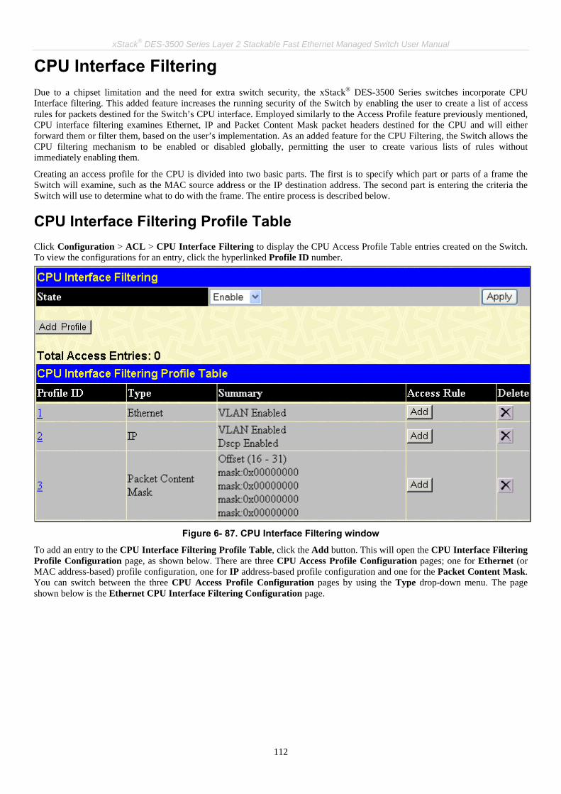
xStack® DES-3500 Series Layer 2 Stackable Fast Ethernet Managed Switch User Manual
112
CPU Interface Filtering Due to a chipset limitation and the need for extra switch security, the xStack® DES-3500 Series switches incorporate CPU Interface filtering. This added feature increases the running security of the Switch by enabling the user to create a list of access rules for packets destined for the Switch’s CPU interface. Employed similarly to the Access Profile feature previously mentioned, CPU interface filtering examines Ethernet, IP and Packet Content Mask packet headers destined for the CPU and will either forward them or filter them, based on the user’s implementation. As an added feature for the CPU Filtering, the Switch allows the CPU filtering mechanism to be enabled or disabled globally, permitting the user to create various lists of rules without immediately enabling them.
Creating an access profile for the CPU is divided into two basic parts. The first is to specify which part or parts of a frame the Switch will examine, such as the MAC source address or the IP destination address. The second part is entering the criteria the Switch will use to determine what to do with the frame. The entire process is described below.
CPU Interface Filtering Profile Table Click Configuration > ACL > CPU Interface Filtering to display the CPU Access Profile Table entries created on the Switch. To view the configurations for an entry, click the hyperlinked Profile ID number.
Figure 6- 87. CPU Interface Filtering window
To add an entry to the CPU Interface Filtering Profile Table, click the Add button. This will open the CPU Interface Filtering Profile Configuration page, as shown below. There are three CPU Access Profile Configuration pages; one for Ethernet (or MAC address-based) profile configuration, one for IP address-based profile configuration and one for the Packet Content Mask. You can switch between the three CPU Access Profile Configuration pages by using the Type drop-down menu. The page shown below is the Ethernet CPU Interface Filtering Configuration page.

xStack® DES-3500 Series Layer 2 Stackable Fast Ethernet Managed Switch User Manual
113
Figure 6- 88. CPU Interface Filtering Profile Configuration window for Ethernet
The following fields may be modified:
Parameter Description
Profile ID (1-5) Type in a unique identifier number for this profile set. This value can be set from 1 - 5.
Type Select profile based on Ethernet (MAC Address), IP address or packet content mask. This will change the menu according to the requirements for the type of profile.
• Select Ethernet to instruct the Switch to examine the layer 2 part of each packet header.
• Select IP to instruct the Switch to examine the IP address in each frame's header. • Select Packet Content Mask to specify a mask to hide the content of the packet
header.
VLAN Selecting this option instructs the Switch to examine the VLAN identifier of each packet header and use this as the full or partial criterion for forwarding.
Source MAC Source MAC Mask - Enter a MAC address mask for the source MAC address.
Destination MAC Destination MAC Mask - Enter a MAC address mask for the destination MAC address.
802.1p Enter a value from 0-7 to specify that the access profile will apply only to packets with this 802.1p priority value.
Ethernet type Selecting this option instructs the Switch to examine the Ethernet type value in each frame's header.
Click Apply to set this entry in the Switch’s memory.

xStack® DES-3500 Series Layer 2 Stackable Fast Ethernet Managed Switch User Manual
114
The page shown below is the CPU Interface Filtering Profile Configuration for IP page.
Figure 6- 89. CPU Interface Filtering Profile Configuration window for IP
The following parameters can be modified:
Parameter Description Profile ID (1-5) Type in a unique identifier number for this profile set. This value can be set from 1 - 5.
Type Select profile based on Ethernet (MAC Address), IP address or Packet Content Mask. This will change the menu according to the requirements for the type of profile.
• Select Ethernet to instruct the Switch to examine the layer 2 part of each packet header.
• Select IP to instruct the Switch to examine the IP address in each frame's header. • Select Packet Content Mask to specify a mask to hide the content of the packet
header.
VLAN Selecting this option instructs the Switch to examine the VLAN part of each packet header and use this as the, or part of the criterion for forwarding.

xStack® DES-3500 Series Layer 2 Stackable Fast Ethernet Managed Switch User Manual
115
Source IP Mask Enter an IP address mask for the source IP address.
Destination IP Mask Enter an IP address mask for the destination IP address.
DSCP Selecting this option instructs the Switch to examine the DiffServ Code part of each packet header and use this as the, or part of the criterion for forwarding.
Protocol Selecting this option instructs the Switch to examine the protocol type value in each frame's header. You must then specify what protocol(s) to include according to the following guidelines: Select ICMP to instruct the Switch to examine the Internet Control Message Protocol (ICMP) field in each frame's header.
• Select Type to further specify that the access profile will apply an ICMP type value, or specify Code to further specify that the access profile will apply an ICMP code value.
Select IGMP to instruct the Switch to examine the Internet Group Management Protocol (IGMP) field in each frame's header.
• Select Type to further specify that the access profile will apply an IGMP type value.
Select TCP to use the TCP port number contained in an incoming packet as the forwarding criterion. Selecting TCP requires that you specify a source port mask and/or a destination port mask. The user may also identify which flag bits to filter. Flag bits are parts of a packet that determine what to do with the packet. The user may filter packets by filtering certain flag bits within the packets, by checking the boxes corresponding to the flag bits of the TCP field. The user may choose between urg (urgent), ack (acknowledgement), psh (push), rst (reset), syn (synchronize), fin (finish).
• src port mask - Specify a TCP port mask for the source port in hex form (hex 0x0-0xffff), which you wish to filter.
• dest port mask - Specify a TCP port mask for the destination port in hex form (hex 0x0-0xffff) which you wish to filter.
Select UDP to use the UDP port number contained in an incoming packet as the forwarding criterion. Selecting UDP requires that you specify a source port mask and/or a destination port mask.
• src port mask - Specify a TCP port mask for the source port in hex form (hex 0x0-0xffff).
• dest port mask - Specify a TCP port mask for the destination port in hex form (hex 0x0-0xffff).
protocol id - Enter a value defining the protocol ID in the packet header to mask. Specify the protocol ID mask in hex form (hex 0x0-0xffffffff).
Click Apply to set this entry in the Switch’s memory.
The page shown below is the CPU Interface Filtering Profile Configuration window for the Packet Content Mask.

xStack® DES-3500 Series Layer 2 Stackable Fast Ethernet Managed Switch User Manual
116
Figure 6- 90. CPU Interface Filtering Profile Configuration window for Packet Content Mask
This screen will aid the user in configuring the Switch to mask packet headers beginning with the offset value specified. The following fields are used to configure the Packet Content Mask:
Parameter Description
Profile ID (1-4) Type in a unique identifier number for this profile set. This value can be set from 1 - 5.
Type Select profile based on Ethernet (MAC Address), IP address or packet content mask. This will change the menu according to the requirements for the type of profile.
• Select Ethernet to instruct the Switch to examine the layer 2 part of each packet header.
• Select IP to instruct the Switch to examine the IP address in each frame's header. • Select Packet Content Mask to specify a mask to hide the content of the packet
header.
Offset This field will instruct the Switch to mask the packet header beginning with the offset value specified:
• value (0-15) - Enter a value in hex form to mask the packet from the beginning of the

xStack® DES-3500 Series Layer 2 Stackable Fast Ethernet Managed Switch User Manual
117
packet to the 15th byte. • value (16-31) – Enter a value in hex form to mask the packet from byte 16 to byte 31. • value (32-47) – Enter a value in hex form to mask the packet from byte 32 to byte 47. • value (48-63) – Enter a value in hex form to mask the packet from byte 48 to byte 63. • value (64-79) – Enter a value in hex form to mask the packet from byte 64 to byte 79.
Click Apply to implement changes made. To establish the rule for a previously created CPU Access Profile: Click Configuraion > ACL > CPU Interface Filtering to open the CPU Interface Filtering Profile Table. In this window, the user may add a rule to a previously created CPU access profile by clicking the corresponding Add Rule button.
Figure 6- 91. CPU Interface Filtering Rule Table
Click the Add Rule button to continue on to the CPU Interface Filtering Rule Table window. A new window, for Ethernet, IP and Packet Content will open as shown in the examples below. To change a rule for a previously created CPU Access Profile Rule: In this window, the user may change a rule that has been previously created by clicking the corresponding Modify button of the entry.
Figure 6- 92. CPU Interface Filtering window
The CPU Interface Filtering Rule Table will open. Click to observe a previously created rule or to delete. The following window is the configuration page for the Ethernet Rule.

xStack® DES-3500 Series Layer 2 Stackable Fast Ethernet Managed Switch User Manual
118
Figure 6- 93. CPU Interface filtering rule Configuration window for Ethernet
To set the CPU Access Rule for Ethernet, adjust the following parameters and click Apply.
Parameters Description
Profile ID This is the identifier number for this profile set.
Mode Select Permit to specify that the packets that match the access profile are forwarded by the Switch, according to any additional rule added (see below). Select Deny to specify that packets that match the access profile are not forwarded by the Switch and will be filtered.
Access ID Type in a unique identifier number for this access and priority. This value can be set from 1 - 65535.
Type Selected profile based on Ethernet (MAC Address), IP address or Packet Content. • Ethernet instructs the Switch to examine the layer 2 part of each packet header. • IP instructs the Switch to examine the IP address in each frame's header. • Packet Content Mask instructs the Switch to examine the packet header.
VLAN Name Allows the entry of a name for a previously configured VLAN.
Source MAC Source MAC Address - Enter a MAC Address for the source MAC address.
Destination MAC Destination MAC Address - Enter a MAC Address mask for the destination MAC address.
802.1P (0-7) Enter a value from 0-7 to specify that the access profile will apply only to packets with this 802.1p priority value.
Ethernet Type Specifies that the access profile will apply only to packets with this hexadecimal 802.1Q Ethernet type value (hex 0x0-0xffff) in the packet header. The Ethernet type value may be set in the form: hex 0x0-0xffff, which means the user may choose any combination of letters and numbers ranging from a-f and from 0-9999.

xStack® DES-3500 Series Layer 2 Stackable Fast Ethernet Managed Switch User Manual
119
To view the settings of a previously configured rule, click in the CPU Interface Filtering Rule Table to view the following screen:
Figure 6- 94. CPU Interface Filtering Rule Display for Ethernet
The following window is the CPU Interface Filtering Rule Configuration for IP.
Figure 6- 95. CPU Interface Filtering Rule Configuration window for IP

xStack® DES-3500 Series Layer 2 Stackable Fast Ethernet Managed Switch User Manual
120
Configure the following CPU Interface Filtering Rule Configuration settings for IP:
Parameter Description
Profile ID This is the identifier number for this profile set.
Mode Select Permit to specify that the packets that match the access profile are forwarded by the Switch, according to any additional rule added (see below). Select Deny to specify that packets that match the access profile are not forwarded by the Switch and will be filtered.
Access ID Type in a unique identifier number for this access. This value can be set from 1 -65535.
Type Selected profile based on Ethernet (MAC Address), IP address or Packet Content. • Ethernet instructs the Switch to examine the layer 2 part of each packet header. • IP instructs the Switch to examine the IP address in each frame's header. • Packet Content Mask instructs the Switch to examine the packet header.
VLAN Name Allows the entry of a name for a previously configured VLAN.
Source IP Source IP Address - Enter an IP Address mask for the source IP address.
Destination IP Destination IP Address- Enter an IP Address mask for the destination IP address.
Dscp (0-63) This field allows the user to enter a DSCP value in the space provided, which will instruct the Switch to examine the DiffServ Code part of each packet header and use this as the, or part of the criterion for forwarding. The user may choose a value between 0 and 63.
Protocol This field allows the user to modify the protocol used to configure the CPU Interface Filtering Rule Table; depending on which protocol the user has chosen in the CPU Interface Filtering Profile Table.
To view the settings of a previously configured rule, click in the CPU Interface Filtering Rule Table to view the following screen:
Figure 6- 96. CPU Interface Filtering Rule Display for IP

xStack® DES-3500 Series Layer 2 Stackable Fast Ethernet Managed Switch User Manual
121
The following window is the CPU Interface Filtering Rule Configuration for Packet Content.
Figure 6- 97. CPU Interface Filtering Rule Configuration window for Packet Content Mask
To set the rule for CPU Packet Content, adjust the following parameters and click Apply.
Parameters Description
Profile ID This is the identifier number for this profile set.
Mode Select Permit to specify that the packets that match the access profile are forwarded by the Switch, according to any additional rule added (see below). Select Deny to specify that packets that match the access profile are not forwarded by the Switch and will be filtered.
Access ID Type in a unique identifier number for this access. This value can be set from 1 - 65535.
Type Selected profile based on Ethernet (MAC Address), IP address or Packet Content.

xStack® DES-3500 Series Layer 2 Stackable Fast Ethernet Managed Switch User Manual
122
• Ethernet instructs the Switch to examine the layer 2 part of each packet header. • IP instructs the Switch to examine the IP address in each frame's header. • Packet Content Mask instructs the Switch to examine the packet header.
Offset This field will instruct the Switch to mask the packet header beginning with the offset value specified:
• value (0-15) - Enter a value in hex form to mask the packet from the beginning of the packet to the 15th byte.
• value (16-31) - Enter a value in hex form to mask the packet from byte 16 to byte 31. • value (32-47) - Enter a value in hex form to mask the packet from byte 32 to byte 47. • value (48-63) - Enter a value in hex form to mask the packet from byte 48 to byte 63. • value (64-79) - Enter a value in hex form to mask the packet from byte 64 to byte 79.
To view the settings of a previously correctly configured rule, click in the Access Rule Table to view the following screen:
Figure 6- 98. CPU Interface Filtering Rule Display for IP

xStack® DES-3500 Series Layer 2 Stackable Fast Ethernet Managed Switch User Manual
123
Time Range Settings The Time Range window is used in conjunction with the Access Profile feature to determine a starting point and an ending point, based on days of the week, and when an Access Profile configuration will be enabled on the Switch. Once configured here, the time range settings are to be applied to an access profile rule using the Access Profile table. The user may enter up to 64 time range entries on the Switch. To open this window, click Configuration > Time Range Settings:
Figure 6- 99. Time Range Settings window
To delete an entry click the corresponding , to view a previously configured time range entry click the following window will be displayed.
Figure 6- 100. Time Range Settings window – View
To return to the Time Range Configuration window, click the hyperlinked Return to Time Range Settings.
IP-MAC Binding The IP network layer uses a four-byte address. The Ethernet link layer uses a six-byte MAC address. Binding these two address types together allows the transmission of data between the layers. The primary purpose of IP-MAC binding is to restrict the access to a switch to a number of authorized users. Only the authorized client can access the Switch’s port by checking the pair of IP-MAC addresses with the pre-configured database. If an unauthorized user tries to access an IP-MAC binding enabled port, the system will block the access by dropping its packet. The maximum number of IP-MAC binding entries is dependant on chip capability (e.g. the ARP table size) and storage size of the device. For the xStack® DES-3500 Series switches, the maximum number of IP-MAC Binding entries is 512. The creation of authorized users can be manually configured by CLI or Web. The function is port-based, meaning a user can enable or disable the function on the individual port.
ACL Mode Due to some special cases that have arisen with the IP-MAC binding, this Switch has been equipped with a special ACL Mode for IP-MAC Binding, which should alleviate this problem for users. When enabled in the IP-MAC Binding Port window, the Switch will create two entries in the Access Profile Table as shown below. The entries may only be created if there are at least two Access Profile IDs available on the Switch. If not, when the ACL Mode is enabled, an error message will be prompted to the user. When the ACL Mode is enabled, the Switch will only accept IP packets from a created entry in the IP-MAC Binding Setting window. All others will be discarded.

xStack® DES-3500 Series Layer 2 Stackable Fast Ethernet Managed Switch User Manual
124
To view the particular configurations associated with these two entries, click their corresponding hyperlinked Profile IDs, which will display the following:
Figure 6- 101. Access Profile Entry Display for IP-MAC ACL Mode Enabled Entries
These two entries cannot be modified or deleted using the Access Profile Table, and any attempt to do so will result in the following warning message:
Figure 6- 102. IP-MAC ACL Mode warning
The user may only remove these two entries by disabling the ACL Mode in the IP-MAC Binding Port window. Also, rules will be created for every port on the Switch. To view the ACL rule configurations set for the ACL mode, click the corresponding Modify button of the entry in the Access Profile Table, which will produce an Access Rule Table as the next figure shows.
Figure 6- 103. Access Profile Table for IP-MAC Binding rule

xStack® DES-3500 Series Layer 2 Stackable Fast Ethernet Managed Switch User Manual
125
NOTE: When configuring the ACL mode function of the IP-MAC binding function, please pay close attention to previously set ACL entries. Since the ACL mode entries will fill the first two available access profiles and access profile IDs denote the ACL priority, the ACL mode entries may take precedence over other configured ACL entries. This may render some user-defined ACL parameters inoperable due to the overlapping of settings combined with the ACL entry priority (defined by profile ID). For more information on ACL settings, please see “Configuring the Access Profile” section mentioned previously in this chapter.
NOTE: Once ACL profiles have been created by the Switch through the IP-MAC binding function, the user cannot modify, delete or add ACL rules to these ACL mode access profile entries. Any attempt to modify, delete or add ACL rules will result in a configuration error as seen in the previous figure.
NOTE: When uploading configuration files to the Switch, be aware of the ACL configurations loaded, as compared to the ACL mode access profile entries set by this function, which may cause both access profile types to experience problems.
The user may view the configurations on a port-by-port basis by clicking the View button under the Display heading of the corresponding port entry. These entries cannot be modified or deleted, and new rules cannot be added. Yet, these windows will offer vital information to the user when configuring other access profile entries. Note that the option, Flow Meter, is only available to be configured for ACL owner. Click Next to view the next page of rules. The user may also search for an entry by Access ID by entering that ID into the field and clicking Find.
b
Figure 6- 104 Access Rule Table for IP-MAC Binding rule (Modify)

xStack® DES-3500 Series Layer 2 Stackable Fast Ethernet Managed Switch User Manual
126
IP-MAC Binding Port This window is used to enable or disable IP-MAC binding on specific ports of the Switch. Select a port or a range of ports with the From and To fields. Enable or disable the port with the State field. Enable or disable zero IP address with the Allow Zero IP field. The user may also enable the ACL Mode for IP-MAC Binding which will create two Access Profile Entries on the Switch, as previously stated. Click Apply to save changes. To view this window click, Configuration > IP-MAC Binding > IP-MAC Binding Port.
Figure 6- 105. IP-MAC Binding Ports window

xStack® DES-3500 Series Layer 2 Stackable Fast Ethernet Managed Switch User Manual
127
IP-MAC Binding Table The window shown below can be used to create IP-MAC binding entries. Enter the IP and MAC addresses of the authorized users in the appropriate fields and click Add. To modify either the IP address or the MAC address of the binding entry, make the desired changes in the appropriate field and Click Modify. To find an IP-MAC binding entry, enter the IP and MAC addresses and click Find. To delete an entry click Delete. To clear all the entries from the table click Delete All. To view this window click, Configuration > IP-MAC Binding > IP-MAC Binding Table.
Figure 6- 106. IP-MAC Binding Table window
The following fields can be set or modified:
Parameter Description
IP Address Enter the IP address you wish to bind to the MAC address set below.
MAC Address Enter the MAC address you wish to bind to the IP Address set above.
All Ports Click this check box to configure this IP-MAC binding entry (IP Address + MAC Address) for all ports on the Switch.
Ports Specify the switch ports for which to configure this IP-MAC binding entry (IP Address + MAC Address).
Mode The user may set the IP-MAC Binding Mode here by using the pull-down menu. The choices are: ARP – Choosing this selection will set a normal IP-Mac Binding entry for the IP address and MAC address entered. ACL – Choosing this entry will allow only packets from the source IP-MAC binding entry created here. All other packets with a different IP address will be discarded by the Switch. This mode can only be used if the ACL Mode has been enabled in the IP-MAC Binding Ports window as seen previously.

xStack® DES-3500 Series Layer 2 Stackable Fast Ethernet Managed Switch User Manual
128
IP-MAC Binding Blocked This window is used to view unauthorized devices that have been blocked by IP-MAC binding restrictions. To view this window click, Configuration > IP-MAC Binding > IP-MAC Binding Blocked.
Figure 6- 107. IP-MAC Binding Blocked window
To find an unauthorized device that has been blocked by the IP-MAC binding restrictions, enter the VLAN name and MAC Address in the appropriate fields and click Find. To delete an entry click the delete button next to the entry’s MAC address. To delete all the entries in the IP-MAC Binding Blocked Table click Delete All.
DHCP Snooping Entries This table is used to enable and view dynamic entries on specific ports. To enable particular port settings, enter the port range and click Apply. To delete an entry, click Delete. To view this window click, Configuration > IP-MAC Binding > IP-MAC Binding DHCP Snooping.
Figure 6- 108. IP-MAC Binding DHCP Snooping window

xStack® DES-3500 Series Layer 2 Stackable Fast Ethernet Managed Switch User Manual
129
IP-MAC Binding Permit IP Pool This table is used to enable and view IP-MAC Binding Permit IP Pool entries on specific ports. To enable particular port settings, enter the port range and click Add. To modify a previously created entry, enter the IP Address range and click Modify, to delete an entry, click Delete. To view this window click, Configuration > IP-MAC Binding > IP-MAC Binding Permit IP Pool.
Figure 6- 109. IP-MAC Binding DHCP Snooping window

xStack® DES-3500 Series Layer 2 Stackable Fast Ethernet Managed Switch User Manual
130
Limited IP Multicast Range The Limited IP Multicast Range window allows the user to specify which multicast address(es) reports are to be received on specified ports on the switch. This function will therefore limit the number of reports received and the number of multicast groups configured on the Switch. The user may set an IP address or range of IP addresses to accept reports (Permit) or deny reports (Deny) coming into the specified switch ports.
Limited IP Multicast Range Profile Settings This window is used to create a multicast address profile. To create a new profile specify the multicast ranges of the multicast addresses in the profile by entering the lowest and highest multicast IP addresses of the range into From Multicast IP and To Multicast IP fields. Click Apply to implement the settings. The new multicast range profile will be listed in The Port Information Table. To remove the existing profile from The Port Information Table list, click the corresponding button under the “Delete” heading. To view this window click, Configuration > Limited IP Multicast Range > Limited IP Multicast Range Profile Settings.
Figure 6- 110. Limited Multicast Range Profile Settings window
Parameter Description
Name Enter a meaningful description for the profile.
From Multicast IP Enter the lowest multicast IP address of the range.
To Multicast IP Enter the highest multicast IP address of the range.

xStack® DES-3500 Series Layer 2 Stackable Fast Ethernet Managed Switch User Manual
131
Limited IP Multicast Range Status Setting After Multicast Range Profiles are created, you may start to configure the multicast address filtering function on a port or a range of ports by configuring the Limited IP Multicast Range Status window as below. To view the following window, click Configuration > Limited IP Multicast Range > Limited IP Multicast Range Status Settings window.
Figure 6- 111 Limited Multicast Range Status Settings window
Parameter Description
From…To Select a port or group of ports using the pull-down menus.
State Toggle the State field to either Enabled or Disabled a given port or group of ports where access is to be either permitted or denied.
Access Two options are available: Permint and Deny. The default mode is Permit. Permint specifies that the packet that match the addresses defined in the profiles will be permitted. Deny specifies that the packet that match the addresses defined in the profiles will be denied.

xStack® DES-3500 Series Layer 2 Stackable Fast Ethernet Managed Switch User Manual
132
Click Apply to implement the configuration.
Limited IP Multicast Range Setting The Limited IP Multicast Range Settings enables the user to configure the ports on the switch that will be involved in the Limited IP Multicast Range. The user can configure the range of multicast ports that will be accepted by the source ports to be forwarded to the receiver ports. To configure these settings, click Configuration > Limited IP Multicast Range > Limited IP Multicast Range Settings.
Figure 6- 112 Limited Multicast Range Settings window
To add a new Limited IP Multicast Range click Add, the following window will be displayed. To search for a range use the drop down menu to select the port and click Find.
Figure 6- 113 Limited Multicast Range Settings window (Add)
Use the drop down menu to select the range of ports that will be included in the Limited IP Multicast Range, enter the previously configured name for the range and click Apply. To view the Port Information Table click, the hyperlinked Show The Port Information Table.
Figure 6- 114 Limited Multicast Range Settings window (Add)
To remove an entry, click the corresponding button under “Delete” heading.

xStack® DES-3500 Series Layer 2 Stackable Fast Ethernet Managed Switch User Manual
133
Layer 3 IP Networking Static ARP Table The Address Resolution Protocol (ARP) is a TCP/IP protocol that converts IP addresses into physical addresses. This table allows network managers to view, define, modify and delete ARP information for specific devices. Static entries can be defined in the ARP Table. When static entries are defined, a permanent entry is entered and is used to translate IP addresses to MAC addresses. To open the Static ARP Table click, Configuration > Layer 3 IP Networking > Static ARP Settings.
Figure 6- 115. Static ARP Settings window
To add a new entry, click the Add button, the following window will be displayed:
Figure 6- 116. Static ARP Table – Add a New Entry window
To modify an entry, click the Modify button, the following window will be displayed:
Figure 6- 117. Static ARP Table - Modify
The following fields can be set:
Parameter Description
IP Address The IP address of the ARP entry.
MAC Address The MAC address of the ARP entry.
After entering the IP Address and MAC Address of the Static ARP entry, click Apply to implement the new entry. To completely clear the Static ARP Settings, click the Clear All button.
NOTE: The Switch supports up to 255 static ARP entries.
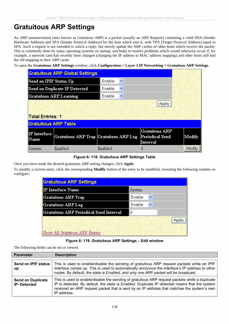
xStack® DES-3500 Series Layer 2 Stackable Fast Ethernet Managed Switch User Manual
134
Gratuitous ARP Settings An ARP announcement (also known as Gratuitous ARP) is a packet (usually an ARP Request) containing a valid SHA (Sender Hardware Address) and SPA (Sender Protocol Address) for the host which sent it, with TPA (Target Protocol Address) equal to SPA. Such a request is not intended to solicit a reply, but merely update the ARP caches of other hosts which receive the packet. This is commonly done by many operating systems on startup, and helps to resolve problems which would otherwise occur if, for example, a network card had recently been changed (changing the IP address to MAC address mapping) and other hosts still had the old mapping in their ARP cache. To open the Gratuitous ARP Settings window, click Configuration > Layer 3 IP Networking > Gratuitous ARP Settings.
Figure 6- 118. Gratuitous ARP Settings Table
Once you have made the desired gratuitous ARP setting changes, click Apply. To modify a current entry, click the corresponding Modify button of the entry to be modified, revealing the following window to configure:
Figure 6- 119. Gratuitous ARP Settings – Edit window
The following fields can be set or viewed:
Parameter Description
Send on IPIF status up
This is used to enable/disable the sending of gratuitous ARP request packets while an IPIF interface comes up. This is used to automatically announce the interface’s IP address to other nodes. By default, the state is Enabled, and only one ARP packet will be broadcast.
Send on Duplicate IP- Detected
This is used to enable/disable the sending of gratuitous ARP request packets while a duplicate IP is detected. By default, the state is Enabled. Duplicate IP detected means that the system received an ARP request packet that is sent by an IP address that matches the system’s own IP address.
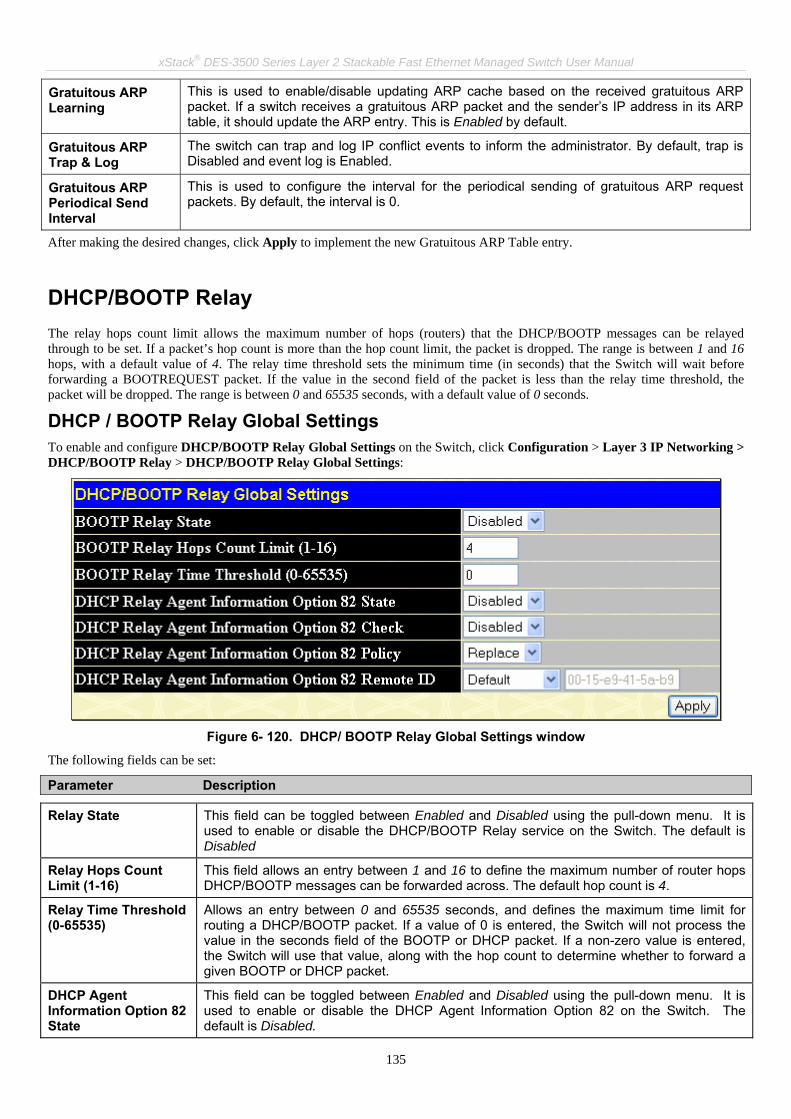
xStack® DES-3500 Series Layer 2 Stackable Fast Ethernet Managed Switch User Manual
135
Gratuitous ARP Learning
This is used to enable/disable updating ARP cache based on the received gratuitous ARP packet. If a switch receives a gratuitous ARP packet and the sender’s IP address in its ARP table, it should update the ARP entry. This is Enabled by default.
Gratuitous ARP Trap & Log
The switch can trap and log IP conflict events to inform the administrator. By default, trap is Disabled and event log is Enabled.
Gratuitous ARP Periodical Send Interval
This is used to configure the interval for the periodical sending of gratuitous ARP request packets. By default, the interval is 0.
After making the desired changes, click Apply to implement the new Gratuitous ARP Table entry.
DHCP/BOOTP Relay The relay hops count limit allows the maximum number of hops (routers) that the DHCP/BOOTP messages can be relayed through to be set. If a packet’s hop count is more than the hop count limit, the packet is dropped. The range is between 1 and 16 hops, with a default value of 4. The relay time threshold sets the minimum time (in seconds) that the Switch will wait before forwarding a BOOTREQUEST packet. If the value in the second field of the packet is less than the relay time threshold, the packet will be dropped. The range is between 0 and 65535 seconds, with a default value of 0 seconds.
DHCP / BOOTP Relay Global Settings To enable and configure DHCP/BOOTP Relay Global Settings on the Switch, click Configuration > Layer 3 IP Networking > DHCP/BOOTP Relay > DHCP/BOOTP Relay Global Settings:
Figure 6- 120. DHCP/ BOOTP Relay Global Settings window
The following fields can be set:
Parameter Description
Relay State This field can be toggled between Enabled and Disabled using the pull-down menu. It is used to enable or disable the DHCP/BOOTP Relay service on the Switch. The default is Disabled
Relay Hops Count Limit (1-16)
This field allows an entry between 1 and 16 to define the maximum number of router hops DHCP/BOOTP messages can be forwarded across. The default hop count is 4.
Relay Time Threshold (0-65535)
Allows an entry between 0 and 65535 seconds, and defines the maximum time limit for routing a DHCP/BOOTP packet. If a value of 0 is entered, the Switch will not process the value in the seconds field of the BOOTP or DHCP packet. If a non-zero value is entered, the Switch will use that value, along with the hop count to determine whether to forward a given BOOTP or DHCP packet.
DHCP Agent Information Option 82 State
This field can be toggled between Enabled and Disabled using the pull-down menu. It is used to enable or disable the DHCP Agent Information Option 82 on the Switch. The default is Disabled.

xStack® DES-3500 Series Layer 2 Stackable Fast Ethernet Managed Switch User Manual
136
Enabled –When this field is toggled to Enabled the relay agent will insert and remove DHCP relay information (option 82 field) in messages between DHCP servers and clients. When the relay agent receives the DHCP request, it adds the option 82 information, and the IP address of the relay agent (if the relay agent is configured), to the packet. Once the option 82 information has been added to the packet it is sent on to the DHCP server. When the DHCP server receives the packet, if the server is capable of option 82, it can implement policies like restricting the number of IP addresses that can be assigned to a single remote ID or circuit ID. Then the DHCP server echoes the option 82 field in the DHCP reply. The DHCP server unicasts the reply to the back to the relay agent if the request was relayed to the server by the relay agent. The switch verifies that it originally inserted the option 82 data. Finally, the relay agent removes the option 82 field and forwards the packet to the switch port that connects to the DHCP client that sent the DHCP request.
Disabled- If the field is toggled to Disabled the relay agent will not insert and remove DHCP relay information (option 82 field) in messages between DHCP servers and clients, and the check and policy settings will have no effect.
DHCP Agent Information Option 82 Check
This field can be toggled between Enabled and Disabled using the pull-down menu. It is used to enable or disable the Switches ability to check the validity of the packet’s option 82 field. Enabled– When the field is toggled to Enable, the relay agent will check the validity of the packet’s option 82 field. If the switch receives a packet that contains the option-82 field from a DHCP client, the switch drops the packet because it is invalid. In packets received from DHCP servers, the relay agent will drop invalid messages. Disabled- When the field is toggled to Disabled, the relay agent will not check the validity of the packet’s option 82 field.
DHCP Agent Information Option 82 Policy
This field can be toggled between Replace, Drop, and Keep by using the pull-down menu. It is used to set the Switches policy for handling packets when the DHCP Agent Information Option 82 Check is set to Disabled. The default is Replace. Replace- The option 82 field will be replaced if the option 82 field already exists in the packet received from the DHCP client. Drop- The packet will be dropped if the option 82 field already exists in the packet received from the DHCP client. Keep-The option 82 field will be retained if the option 82 field already exists in the packet received from the DHCP client.
DHCP Agent Information Option 82 Remote ID
This field specifies the feature which allows the user to configure the Remote ID as any specific string. When the Remote ID state is set to Default, the switch’s system MAC address is used as the Remote ID. When the Remote ID state is configured to be user-defined, the user-defined string is used as the Remote ID. Note: The maximum number of characters that can be used is 32.
Click Apply to implement any changes that have been made.
NOTE: If the Switch receives a packet that contains the option-82 field from a DHCP client and the information-checking feature is enabled, the switch drops the packet because it is invalid. However, in some instances, you might configure a client with the option-82 field. In this situation, you should disable the information-check feature so that the switch does not remove the option-82 field from the packet. You can configure the action that the switch takes when it receives a packet with existing option-82 information by configuring the DHCP Agent Information Option 82 Policy.

xStack® DES-3500 Series Layer 2 Stackable Fast Ethernet Managed Switch User Manual
137
The Implementation of DHCP Information Option 82 in the xStack® DES-3500 Series switches The config dhcp_relay option_82 command configures the DHCP relay agent information option 82 setting of the switch. The formats for the circuit ID sub-option and the remote ID sub-option are as follows:
NOTE: For the circuit ID sub-option of a standalone switch, the module field is always zero.
Circuit ID sub-option format:
1. 2. 3. 4. 5. 6. 7.
1 6 0 4 VLAN Module Port
1 byte 1 byte 1 byte 1 byte 2 bytes 1 byte 1 byte
a. Sub-option type b. Length c. Circuit ID type d. Length e. VLAN : the incoming VLAN ID of DHCP client packet. f. Module : For a standalone switch, the Module is always 0; For a stackable switch, the Module is the Unit ID. g. Port : The incoming port number of DHCP client packet, port number starts from 1.
Remote ID sub-option format 1:
1. 2. 3. 4. 5.
2 8 0 6 MAC address
1 byte 1 byte 1 byte 1 byte 6 bytes
1. Sub-option type 2. Length 3. Remote ID type 4. Length 5. MAC address: The Switch’s system MAC address.
Remote ID sub-option format 2 (Using user-defined string as remote ID): 1. 2. 3. 4. 5.
2 n+2 1 n User-defined String
1 byte 1 byte 1 byte 1 byte 6 bytes
1. Sub-option type 2. Length: the string length of the Remote ID suboption 3. Remote ID type 4. Length: the string length of user-defined string 5. User-defined string
Figure 6- 121. Circuit ID and Remote ID Sub-option Format

xStack® DES-3500 Series Layer 2 Stackable Fast Ethernet Managed Switch User Manual
138
DHCP/BOOTP Relay Interface Settings
The DHCP/ BOOTP Relay Interface Settings allows the user to set up a server, by IP address, for relaying DHCP/ BOOTP information to the Switch. The user may enter a previously configured IP interface on the Switch that will be connected directly to the DHCP/BOOTP server using the following window. Properly configured settings will be displayed in the BOOTP Relay Table at the bottom of the following window, once the user clicks the Add button under the Apply heading. The user may add up to four server IPs per IP interface on the Switch. Entries may be deleted by clicking it’s corresponding . To enable and configure DHCP/BOOTP Relay Global Settings on the Switch, click Configuration > Layer 3 IP Networking > DHCP/BOOTP Relay > DHCP/BOOTP Relay Interface Settings:
Figure 6- 122. DHCP/BOOTP Relay Interface Settings and DHCP/BOOTP Relay Interface Table window
The following parameters may be configured or viewed.
Parameter Description
Interface The IP interface on the Switch that will be connected directly to the Server.
Server IP Enter the IP address of the DHCP/BOOTP server. Up to four server IPs can be configured per IP Interface

xStack® DES-3500 Series Layer 2 Stackable Fast Ethernet Managed Switch User Manual
139
DHCP Option 60 Settings
The DHCP Option 60 Settings allows the Switch to monitor Option 60 contents of the DHCP client packets and determine which client packets to relay to the DHCP Server and which packets to drop.
To enable and configure DHCP Option 60 Global Settings on the Switch, click Configuration > Layer 3 IP Networking > DHCP/BOOTP Relay > DHCP Option 60 Settings:
Figure 6- 123. DHCP Option 60 Settings Table window
The following parameters may be configured or viewed.
Parameter Description
Status Use the drop down menu to Enable or Disable the DHCP Option 60 Global Settings.
Default Processing Mode
Use the drop down menu to choose between Drop or Relay. This function allows the User to specify how the Switch will assess the content of the DHCP client packet and decide whether to relay the packet to a DHCP Server or just simply drop it.
Server IP Enter the Server IP Address and click Add.
String A string can map to multiple DHCP servers, but not more than 4 servers at a time, also a DHCP server can map to multiple strings, but not to any more than 50. Enter the String and press Delete to delete the entry.
IP Address Enter the Server IP Address and click Add.
Match Type Use the drop down menu to choose between Exact Match or Partial Match. Exact Match will exactly match the client string to the specified string. Partial Match will only partically match the DHCP client string to the specified string.

xStack® DES-3500 Series Layer 2 Stackable Fast Ethernet Managed Switch User Manual
140
DHCP Option 61 Settings
The DHCP Option 61 Settings allows the Switch to monitor Option 61 contents of the DHCP client packets and determine which client packets to relay to the DHCP Server and which packets to drop.
To enable and configure DHCP Option 61 Global Settings on the Switch, click Configuration > Layer 3 IP Networking > DHCP/BOOTP Relay > DHCP Option 61 Settings:
Figure 6- 124. DHCP Option 60 Settings Table window
The following parameters may be configured or viewed.
Parameter Description
Status Use the drop down menu to Enable or Disable the DHCP Option 61 Global Settings.
Default Processing Mode
Use the drop down menu to choose between Drop or Relay. This function allows the User to specify how the Switch will assess the content of the DHCP client packet and decide whether to relay the packet to a DHCP Server or just simply drop it.
Default Server Enter the IP Address of the Default Server that will be used during processing.
Client ID Use the drop down menu to select String or MAC Address as the identifier.
Mode Use the drop down menu to choose between Exact Match or Partial Match. Exact Match will exactly match the client string to the specified string. Partial Match will only partically match the DHCP client string to the specified string.
IP Address Enter the Server IP Address and click Add.
String A string can map to multiple DHCP servers, but not more than 4 servers at a time, also a DHCP server can map to multiple strings, but not to any more than 50. Enter the String and press Delete to delete the entry.
MAC Address Enter the MAC Address and click Delete to remove the entry.

xStack® DES-3500 Series Layer 2 Stackable Fast Ethernet Managed Switch User Manual
141
DHCP Local Relay Settings
The DHCP Local Relay Settings are used to request packets from the Client to the Server. As a result of the customer’s networking environment, DCHP Local Relay is implemented so that it is independent from the original behavior of DHCP relay. The DHCP Local Relay is also independent from the option82 module in the forwarding way and the content of DHCP request packets from Client to Server. To enable and configure DHCP Local Relay Global Settings on the Switch, click Configuration > Layer 3 IP Networking > DHCP/BOOTP Relay > DHCP Local Relay Settings:
Figure 6- 125. DHCP Local Relay Settings window
The following parameters may be configured or viewed.
Parameter Description
DHCP/BOOTP Local Relay Operation State
Used to Enable or Disable the DHCP/BOOTP Local Relay Operation State.
VLAN Name This is the VLAN Name that identifies the VLAN the user wishes to modify the DHCP/BOOTP Local Relay Settings for.
VID List This is the VID List that identifies the VLAN the user wishes to modify the DHCP/BOOTP Local Relay Settings for.
State Enable or Disable the DHCP/BOOTP Local Relay Settings state.
Click Apply to implement changes made.

xStack® DES-3500 Series Layer 2 Stackable Fast Ethernet Managed Switch User Manual
142
LLDP The Link Layer Discovery Protocol (LLDP) allows stations attached to an IEEE 802 LAN to advertise, to other stations attached to the same IEEE 802 LAN. The major capabilities provided by this system is that it incorporates the station, the management address or addresses of the entity or entities that provide management of those capabilities, and the identification of the station’s point of attachment to the IEEE 802 LAN required by those management entity or entities. The information distributed via this protocol is stored by its recipients in a standard Management Information Base (MIB), making it possible for the information to be accessed by a Network Management System (NMS) through a management protocol such as the Simple Network Management Protocol (SNMP).
LLDP Global Settings To view this window, click Configuration > LLDP > LLDP Global Settings
Figure 6- 126. LLDP Global Settings window
The following parameters can be set:
Parameter Description
LLDP State Used to Enable or Disable LLDP on the Switch.
LLDP Forward Message
Enable or Disable the message forwarding of the LLDP function, to advertise to other stations attached to the same IEEE 802 LAN.
Message TX Interval (5-32768)
This interval controls how often active ports retransmit advertisements to their neighbors. To change the packet transmission interval, enter a value in seconds (5 to 32768).
Message TX Hold Multiplier (2-10)
This function calculates the Time-to-Live for creating and transmitting the LLDP advertisements to LLDP neighbors by changing the multiplier used by an LLDP Switch. When the Time-to-Live for an advertisement expires the advertised data is then deleted from the neighbor Switch’s MIB.

xStack® DES-3500 Series Layer 2 Stackable Fast Ethernet Managed Switch User Manual
143
Re Init Delay (1-10)
The LLDP reinitialization delay interval is the minimum time that an LLDP port will wait before reinitializing after receiving an LLDP disable command. To change the LLDP Reinit Delay, enter a value in seconds (1 to 10).
TX Delay (1-8192) LLDP TX Delay allows the user to change the minimum time delay interval for any LLDP port which will delay advertising any successive LLDP advertisements due to change in the LLDP MIB content. To change the LLDP TX Delay, enter a value in seconds (1 to 8192).
Notification Interval (5-3600)
LLDP Notification Interval is used to send notifications to configured SNMP trap receiver(s) when an LLDP change is detected in an advertisement received on the port from an LLDP neighbor. To set the LLDP Notification Interval, enter a value in seconds (5 to 3600).
Click Apply to implement changes made.

xStack® DES-3500 Series Layer 2 Stackable Fast Ethernet Managed Switch User Manual
144
Basic LLDP Port Settings To view this window, click Configuration > LLDP > Basic LLDP Port Settings
Figure 6- 127. Basic LLDP Port Settings window
The following parameters can be set:
Parameter Description
From Port/To Port
Use the pull-down menu to select a range of ports to be configured.
Notification State Use the pull-down menu to Enable or Disable the status of the LLDP notification.
Admin State Select the status of the notification, use the drop-down menu to choose between TX, RX, TX And RX or Disabled.
Port Description Use the pull-down menu to Enable or Disable the status of the LLDP Port Description.
System Name Use the pull-down menu to Enable or Disable the status of the LLDP System Name.
System Description
Use the pull-down menu to Enable or Disable the status of the LLDP System Description.
System Use the pull-down menu to Enable or Disable the status of the LLDP System Capabilities.
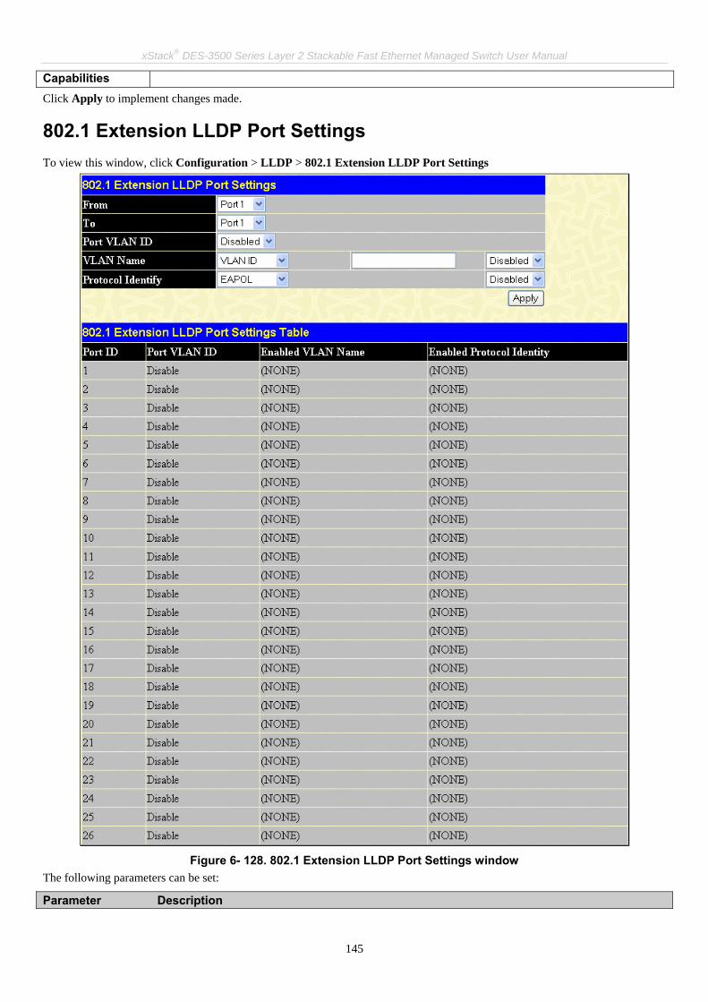
xStack® DES-3500 Series Layer 2 Stackable Fast Ethernet Managed Switch User Manual
145
Capabilities Click Apply to implement changes made.
802.1 Extension LLDP Port Settings To view this window, click Configuration > LLDP > 802.1 Extension LLDP Port Settings
Figure 6- 128. 802.1 Extension LLDP Port Settings window
The following parameters can be set:
Parameter Description

xStack® DES-3500 Series Layer 2 Stackable Fast Ethernet Managed Switch User Manual
146
From Port/To Use the drop-down menu to select a range of ports to be configured.
Port VLAN ID Use the drop-down menu to Enable or Disable the advertise Port VLAN ID.
VLAN Name Use the drop-down menu to Enable or Disable the advertised VLAN ID, VLAN Name or All.
Protocol Identify Use the drop-down menu to Select the advertised Protocol Identity. Select EAPOL, LACP, GVRP, STP or All.
Click Apply to implement changes made.
802.3 Extension LLDP Port Settings To view this window, click Configuration > LLDP > 802.3 Extension LLDP Port Settings
Figure 6- 129. 802.3 Extension LLDP Port Settings window
The following parameters can be set:

xStack® DES-3500 Series Layer 2 Stackable Fast Ethernet Managed Switch User Manual
147
Parameter Description
From Port/To Use the drop-down menu to select a range of ports to be configured.
MAC/PHY Configuration Status
Use the drop-down menu to configure the advertise MAC PHY status of the switch.
Link Aggregation Use the drop-down menu to Enable or Disable the advertise link aggregation state on the Switch.
Maximum Frame Size
Use the drop-down menu to Enable or Disable the advertised Maximum Frame Size.
Click Apply to implement changes made.
LLDP Management Address Settings To view this window, click Configuration > LLDP > LLDP Management Address Settings
Figure 6- 130. LLDP Management Address List window

xStack® DES-3500 Series Layer 2 Stackable Fast Ethernet Managed Switch User Manual
148
The following parameters can be set:
Parameter Description
Port From/To Use the drop-down menu to select a range of ports to be configured.
Address Type/Address
Enter the management ip address or the ip address of the entity you wish to advertise to. IPv4 will ensure the message is sent by the router to ask for the advertisements.
Port State Use the drop-down menu to Enable or Disable the Port State.
Click Find to implement changes made.
LLDP Statistics This window is used to view the settings for LLDP Statistics. To view this window, click Configuration > LLDP > LLDP Statistics
Figure 6- 131. LLDP Statistics window

xStack® DES-3500 Series Layer 2 Stackable Fast Ethernet Managed Switch User Manual
149
LLDP Management Address Table To view this window, Click Configuration > LLDP > LLDP Management Address Table
Figure 6- 132. LLDP Management Address Table window
Enter the IPv4 Address of the LLDP entry and click Find to display the details in the table.
LLDP Local Port Table LLDP Local Port Information window displays the information on a per port basis in the local port brief table shown below. To view this window, click Configuration > LLDP > LLDP Local Port Table
Figure 6- 133. LLDP Local Port Table window

xStack® DES-3500 Series Layer 2 Stackable Fast Ethernet Managed Switch User Manual
150
To view the information on a per port basis click the View (Normal) button, which will display the following window:
Figure 6- 134. LLDP Local Port Information (Normal) window
To view detailed information about MAC/PHY Configuration/Status or Link Aggregration, click the hyperlinked see detailed. To return to the previous window click the hyperlinked Show LLDP Local Port Berif Table. To view more detailed information of individual parameters click the hyperlinked Show LLDP Local Port Detailed Table, which will reveal the following window;
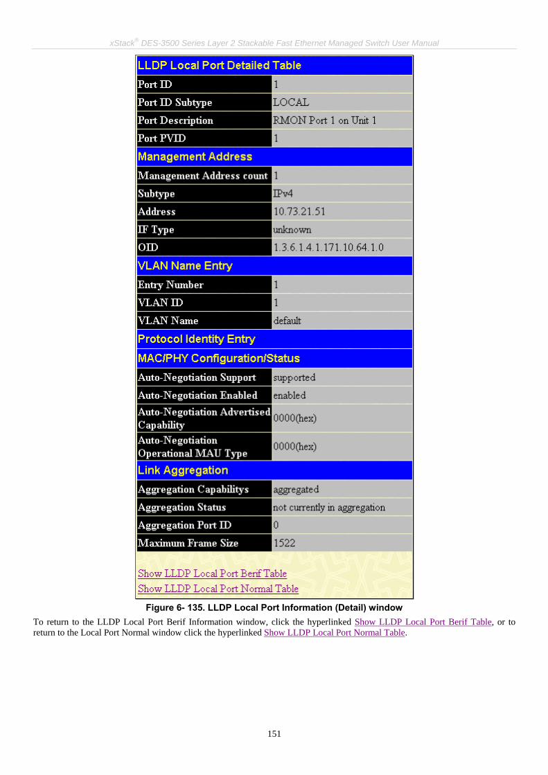
xStack® DES-3500 Series Layer 2 Stackable Fast Ethernet Managed Switch User Manual
151
Figure 6- 135. LLDP Local Port Information (Detail) window
To return to the LLDP Local Port Berif Information window, click the hyperlinked Show LLDP Local Port Berif Table, or to return to the Local Port Normal window click the hyperlinked Show LLDP Local Port Normal Table.

xStack® DES-3500 Series Layer 2 Stackable Fast Ethernet Managed Switch User Manual
152
LLDP Remote Port Information To view this window, click Configuration > LLDP > LLDP Remote Port Table
Figure 6- 136. LLDP Remote Port Information window
Select the port you wish to view by using the drop-down menu and click Find the information will be displayed in the lower half of the table.

xStack® DES-3500 Series Layer 2 Stackable Fast Ethernet Managed Switch User Manual
153
Section 7 Security Management
Tustred Host
User Accounts
Port Access Entity
Access Authentication Control
Secure Sockets Layer (SSL)
Secure Shell (SSH)
SNMP Manager
Safeguard Engine Settings
Filter
ARP Spoofing Prevention
The following section will aid the user in configuring security functions for the Switch. The Switch includes various functions for security, including TACACS, Security IPs, SSL, SSH and SNMP, all discussed in detail in the following section.
Trusted Host Use the Security IP Management to permit remote stations to manage the Switch. If you choose to define one or more designated management stations, only the chosen stations, as defined by IP address, will be allowed management privilege through the web manager or Telnet session. You are allowed to enter IP address or IP submask to manage the Switch, and then click the Apply button to implement the setting. To remove an individual security IP address from the Switch, click the corresponding button under the Delete heading. To remove all security IP addresses from the Switch, click the button. To view this window, click Security Management > Trusted Host, the following window will appear.

xStack® DES-3500 Series Layer 2 Stackable Fast Ethernet Managed Switch User Manual
154
Figure 7- 1. Trusted Host window
User Accounts Use the User Account Management window to control user privileges. To view existing User Accounts, open the Security Management folder and click on the User Accounts link. This will open the User Account Management window, as shown below.
Figure 7- 2. User Accounts Management window
To add a new user, click on the Add button. To modify or delete an existing user, click on the Modify button for that user.
Figure 7- 3. User Accounts Modify Table window - Add

xStack® DES-3500 Series Layer 2 Stackable Fast Ethernet Managed Switch User Manual
155
Add a new user by typing in a User Name, and New Password and retype the same password in the Confirm New Password. Choose the level of privilege (Admin, Operator, or User) from the Access Right drop-down menu and click Apply. To return to the User Account Table click the hyperlinked Show All User Account Entries.
NOTICE: In case of lost passwords or password corruption, please refer to the D-Link website and the White Paper entitled “Password Recovery Procedure”, which will guide you through the steps necessary to resolve this issue.
Figure 7- 4. User Accounts Modify Table window - Modify
Modify or delete an existing user account in the User Account Modify Table. To delete the user account, click on the Delete button. To change the password, type in the New Password and retype it in the Confirm New Password entry field. The level of privilege (Admin, Operator, or User) can be viewed in the Access Right field. To return to the User Account Table click the hyperlinked Show All User Account Entries.

xStack® DES-3500 Series Layer 2 Stackable Fast Ethernet Managed Switch User Manual
156
Port Access Entity (802.1X) 802.1x Port-Based and MAC-Based Access Control The IEEE 802.1x standard is a security measure for authorizing and authenticating users to gain access to various wired or wireless devices on a specified Local Area Network by using a Client and Server based access control model. This is accomplished by using a RADIUS server to authenticate users trying to access a network by relaying Extensible Authentication Protocol over LAN (EAPOL) packets between the Client and the Server. The following figure represents a basic EAPOL packet:
Figure 7- 5. EAPOL Packet
Utilizing this method, unauthorized devices are restricted from connecting to a LAN through a port to which the user is connected. EAPOL packets are the only traffic that can be transmitted through the specific port until authorization is granted. The 802.1x Access Control protocol consists of three components, each of which is vital to creating and maintaining a stable and working Access Control security method.
Figure 7- 6. Three Functions of 802.1x
The following section will explain Client, Authenticator, and Authentication Server in greater detail.

xStack® DES-3500 Series Layer 2 Stackable Fast Ethernet Managed Switch User Manual
157
Authentication Server The Authentication Server is a remote device that is connected to the same network as the Client and Authenticator, must be running a RADIUS Server program and must be configured properly on the Authenticator (Switch). The Authentication Server (RADIUS) must authenticate clients connected to a port on the Switch before attaining any services offered by the Switch on the LAN. The role of the Authentication Server is to certify the identity of the Client attempting to access the network by exchanging secure information between the RADIUS server and the Client through EAPOL packets and, in turn, informs the Switch whether or not the Client is granted access to the LAN and/or switch services.
Figure 7- 7. Authentication Server
Authenticator The Authenticator (the Switch) is an intermediary between the Authentication Server and the Client. The Authenticator serves two purposes when utilizing 802.1x. The first purpose is to request certification information from the Client through EAPOL packets, which is the only information allowed to pass through the Authenticator before access is granted to the Client. The second purpose of the Authenticator is to verify the information gathered from the Client with the Authentication Server, and to then relay that information back to the Client.
Three steps must be implemented on the Switch to properly configure the Authenticator. 1. The 802.1x State must be enabled. (Configuration > Switch Information > Advanced Settings > 802.1x Status) 2. The 802.1x settings must be implemented by port. (Port Access Entity > PAE System Control > Port Capability >
Capability) 3. A RADIUS server must be configured on the Switch. (Port Access Entity > RADIUS Server > Authentic RADIUS
Server)
Figure 7- 8. Authenticator
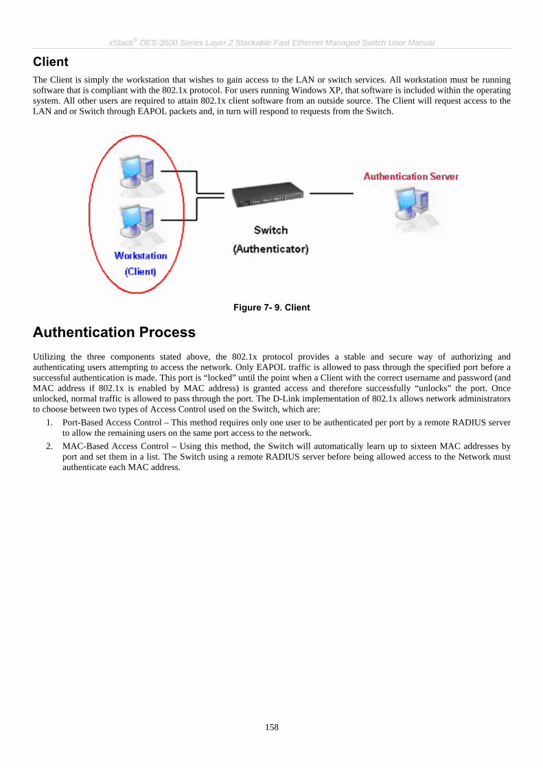
xStack® DES-3500 Series Layer 2 Stackable Fast Ethernet Managed Switch User Manual
158
Client The Client is simply the workstation that wishes to gain access to the LAN or switch services. All workstation must be running software that is compliant with the 802.1x protocol. For users running Windows XP, that software is included within the operating system. All other users are required to attain 802.1x client software from an outside source. The Client will request access to the LAN and or Switch through EAPOL packets and, in turn will respond to requests from the Switch.
Figure 7- 9. Client
Authentication Process Utilizing the three components stated above, the 802.1x protocol provides a stable and secure way of authorizing and authenticating users attempting to access the network. Only EAPOL traffic is allowed to pass through the specified port before a successful authentication is made. This port is “locked” until the point when a Client with the correct username and password (and MAC address if 802.1x is enabled by MAC address) is granted access and therefore successfully “unlocks” the port. Once unlocked, normal traffic is allowed to pass through the port. The D-Link implementation of 802.1x allows network administrators to choose between two types of Access Control used on the Switch, which are:
1. Port-Based Access Control – This method requires only one user to be authenticated per port by a remote RADIUS server to allow the remaining users on the same port access to the network.
2. MAC-Based Access Control – Using this method, the Switch will automatically learn up to sixteen MAC addresses by port and set them in a list. The Switch using a remote RADIUS server before being allowed access to the Network must authenticate each MAC address.

xStack® DES-3500 Series Layer 2 Stackable Fast Ethernet Managed Switch User Manual
159
Port-Based Network Access Control The original intent behind the development of 802.1x was to leverage the characteristics of point-to-point in LANs. Any single LAN segment in such an infrastructures has no more than two devices attached to it, one of which is a Bridge Port. The Bridge Port detects events that indicate the attachment of an active device at the remote end of the link, or an active device becoming inactive. These events can be used to control the authorization state of the Port and initiate the process of authenticating the attached device if the Port is unauthorized. This is the Port-Based Network Access Control.
…802.1XClient
802.1XClient
802.1XClient
802.1XClient
802.1XClient
802.1XClient
802.1XClient
802.1XClient
802.1XClient
Network access controlled port
Network access uncontrolled port
RADIUSServer
Ethernet Switch
Figure 7- 10. Example of Typical Port-Based Configuration
Once the connected Client has successfully been authenticated, the Port then becomes Authorized, and all subsequent traffic on the Port is not subject to access control restriction until an event occurs that causes the Port to become Unauthorized. Hence, if the Port is actually connected to a shared media LAN segment with more than one attached device, successfully authenticating one of the attached devices effectively provides access to the LAN for all devices on the shared segment. Clearly, the security offered in this situation is open to attack.

xStack® DES-3500 Series Layer 2 Stackable Fast Ethernet Managed Switch User Manual
160
MAC-Based Network Access Control
802.1XClient
Network access controlled port
Network access uncontrolled port
RADIUSServer
Ethernet Switch
802.1XClient
802.1XClient
802.1XClient
802.1XClient
802.1XClient
802.1XClient
802.1XClient
802.1XClient
802.1XClient
802.1XClient
802.1XClient
…
Figure 7- 11. Example of Typical MAC-Based Configuration
In order to successfully make use of 802.1x in a shared media LAN segment, it would be necessary to create “virtual” Ports, one for each attached device that required access to the LAN. The Switch would regard the single physical Port connecting it to the shared media segment as consisting of a number of distinct virtual Ports, each virtual Port being independently controlled from the point of view of EAPOL exchanges and authorization state. The Switch learns each attached device’s individual MAC address, and effectively creates a virtual Port that the attached device can then use to communicate with the LAN via the Switch.

xStack® DES-3500 Series Layer 2 Stackable Fast Ethernet Managed Switch User Manual
161
Configure Authenticator To configure the 802.1X Authenticator Settings, click Security > Port Access Entity > Configure Authenticator:
Figure 7- 12. 802.1X Authenticator Settings window
To configure the settings by port, click on the hyperlinked port number under the Port heading, which will display the following table to configure:

xStack® DES-3500 Series Layer 2 Stackable Fast Ethernet Managed Switch User Manual
162
Figure 7- 13. 802.1X Authenticator Settings window (Modify)
This window allows you to set the following features:
Parameter Description
From [ ] To [ ] Enter the port or ports to be set.
AdmCtrlDir Sets the administrative-controlled direction to either in or both. If in is selected, control is only exerted over incoming traffic through the port you selected in the first field. If both are selected, control is exerted over both incoming and outgoing traffic through the controlled port selected in the first field.
PortControl This allows you to control the port authorization state. Select forceAuthorized to disable 802.1X and cause the port to transition to the authorized state without any authentication exchange required. This means the port transmits and receives normal traffic without 802.1X-based authentication of the client. If forceUnauthorized is selected, the port will remain in the unauthorized state, ignoring all attempts by the client to authenticate. The Switch cannot provide authentication services to the client through the interface. If Auto is selected, it will enable 802.1X and cause the port to begin in the unauthorized state, allowing only EAPOL frames to be sent and received through the port. The authentication process begins when the link state of the port transitions from down to up, or when an EAPOL-start frame is received. The Switch then requests the identity of the client and begins relaying authentication messages between the client and the authentication server. The default setting is Auto.
TxPeriod This sets the TxPeriod of time for the authenticator PAE state machine. This value determines the period of an EAP Request/Identity packet transmitted to the client. The default setting is 30 seconds.
QuietPeriod This allows you to set the number of seconds that the Switch remains in the quiet state following a failed authentication exchange with the client. The default setting is 60 seconds.
SuppTimeout This value determines timeout conditions in the exchanges between the Authenticator and the client. The default setting is 30 seconds.

xStack® DES-3500 Series Layer 2 Stackable Fast Ethernet Managed Switch User Manual
163
ServerTimeout This value determines timeout conditions in the exchanges between the Authenticator and the authentication server. The default setting is 30 seconds.
MaxReq The maximum number of times that the Switch will retransmit an EAP Request to the client before it times out of the authentication sessions. The default setting is 2.
ReAuthPeriod A constant that defines a nonzero number of seconds between periodic reauthentication of the client. The default setting is 3600 seconds.
ReAuth Determines whether regular reauthentication will take place on this port. The default setting is Disabled.
Click Apply to implement your configuration changes. To view configurations for the 802.1X Authenticator Settings on a port-by-port basis, see the 802.1X Authenticator Settings table. To return to the Authenticator Table click the hyperlinked Show Authenticators Setting.

xStack® DES-3500 Series Layer 2 Stackable Fast Ethernet Managed Switch User Manual
164
PAE System Control Existing 802.1x port settings are displayed and can be configured using the windows below.
Port Capability Click, Security Management > Port Access Entity > PAE System Control > Port Capability to view the following window:
Figure 7- 14. 802.1x Capability Settings window
To set up the Switch's 802.1x port-based authentication, select which ports are to be configured in the From and To fields. Next, enable the ports by selecting Authenticator from the drop-down menu under Capability. Click Apply to let your change take effect. Configure the following 802.1x capability settings:
Parameter Description

xStack® DES-3500 Series Layer 2 Stackable Fast Ethernet Managed Switch User Manual
165
From and To Ports being configured for 802.1x settings.
Capability Two role choices can be selected: Authenticator - A user must pass the authentication process to gain access to the network. None - The port is not controlled by the 802.1x functions.
Initializing Ports for Port Based 802.1x Existing 802.1x port and MAC settings are displayed and can be configured using the window below. Click Security Management > Port Access Entity > PAE System Control > Initialize Port(s) to open the following window:
Figure 7- 15. Initialize Port window
This window allows the initialization of a port or group of ports. The Initialize Port Table in the bottom half of the window displays the current status of the port(s). This window displays the following information:
Parameter Description
From and To Select ports to be initialized.
Port A read-only field indicating a port on the Switch.
MAC Address The MAC address of the Switch connected to the corresponding port, if any.
Auth PAE State The Authenticator PAE State will display one of the following: Initialize, Disconnected, Connecting, Authenticating, Authenticated, Aborting, Held, ForceAuth, ForceUnauth, and N/A.
Backend State The Backend Authentication State will display one of the following: Request, Response, Success, Fail, Timeout, Idle, Initialize, and N/A.
Port Status The status of the controlled port can be Authorized, Unauthorized, or N/A.

xStack® DES-3500 Series Layer 2 Stackable Fast Ethernet Managed Switch User Manual
166
Initializing Ports for MAC Based 802.1x
To initialize ports for the MAC side of 802.1x, the user must first enable 802.1x by MAC address in the Advanced Settings window. Click Security Management > Port Access Entity > PAE System Control > Initialize Port(s) to open the following window:
Figure 7- 16. Initialize Port(s) window (MAC based 802.1x)
To initialize ports, first choose the range of ports in the From and To field. Then the user must specify the MAC address to be initialized by entering it into the MAC Address field and checking the corresponding check box. To begin the initialization, click Apply.
NOTE: The user must first globally enable 802.1X in the Switch Information (Advanced Settings) window in the Configuration folder before initializing ports. Information in the Initialize Ports Table cannot be viewed before enabling 802.1X.
Reauthenticate Port(s) for Port Based 802.1x This window allows you to reauthenticate a port or group of ports by choosing a port or group of ports by using the pull down menus From and To and clicking Apply. The Reauthenticate Port Table displays the current status of the reauthenticated port(s) once you have clicked Apply. Click Security Management > Port Access Entity > PAE System Control > Reauthenticate Port(s) to open the Reauthenticate Port(s) window:
Figure 7- 17. Reauthenticate Port (Port Based 802.1x) window
This window displays the following information:
Parameter Description
Port The port number of the reauthenticated port.
MAC Address Displays the physical address of the Switch where the port resides.
Auth State The Authenticator State will display one of the following: Initialize, Disconnected, Connecting, Authenticating, Authenticated, Aborting, Held, ForceAuth, ForceUnauth, and N/A.

xStack® DES-3500 Series Layer 2 Stackable Fast Ethernet Managed Switch User Manual
167
BackendState The Backend State will display one of the following: Request, Response, Success, Fail, Timeout, Idle, Initialize, and N/A.
OpenDir Operational Controlled Directions are both and in.
PortStatus The status of the controlled port can be Authorized, Unauthorized, or N/A.
Reauthenticate Port(s) for MAC Based 802.1x This window allows you to reauthenticate a port or group of ports by using the pull down menus From and To to select the ports , enter a MAC Address and click Apply. Click Security Management > Port Access Entity > PAE System Control > Reauthenticate Port(s) to open the Reauthenticate Port(s) window:
Figure 7- 18. Reauthenticate Port (MAC Based 802.1x) window
RADIUS Server The RADIUS feature of the Switch allows you to facilitate centralized user administration as well as providing protection against a sniffing, active hacker. The Web Manager offers three windows. Click Security Management > Port Access Entity > RADIUS Server > Authentic RADIUS Server to open the RADIUS Server Authentication Setting window shown below:
Figure 7- 19. RADIUS Server Authentication Setting window

xStack® DES-3500 Series Layer 2 Stackable Fast Ethernet Managed Switch User Manual
168
This window displays the following information:
Parameter Description
Succession Choose the desired RADIUS server to configure: First, Second or Third.
RADIUS Server Set the RADIUS server IP.
Authentic Port Set the RADIUS authentic server(s) UDP port. The default port is 1812.
Accounting Port Set the RADIUS account server(s) UDP port. The default port is 1813.
Key Set the key the same as that of the RADIUS server.
Confirm Key Confirm the shared key is the same as that of the RADIUS server.
Accounting Method This allows you to Add/Modify or Delete the RADIUS Server.
Guest VLANs
Figure 7- 20. Guest VLAN Authentication Process
Limitations Using the Guest VLAN 1. Guest VLANs are only supported for port-based VLANs. MAC-based VLANs cannot undergo this procedure. 2. Ports supporting Guest VLANs cannot be GVRP enabled and vice versa. 3. A port cannot be a member of a Guest VLAN and a static VLAN simultaneously. 4. Once a client has been accepted into the target VLAN, it can no longer access the Guest VLAN. 5. If a port is a member of multiple VLANs, it cannot become a member of the Guest VLAN.
On 802.1x security enabled networks, there is a need for non 802.1x supported devices to gain limited access to the network, due to lack of the proper 802.1x software or incompatible devices, such as computers running Windows 98 or lower operating systems, or the need for guests to gain access to the network without full authorization. To supplement these circumstances, this switch now implements Guest 802.1x VLANs. These VLANs should have limited access rights and features separate from other VLANs on the network.
To implement Guest 802.1x VLANs, the user must first create a VLAN on the network with limited rights and then enable it as an 802.1x guest VLAN. Then the administrator must configure the guest accounts accessing the Switch to be placed in a Guest VLAN when trying to access the Switch. Upon initial entry to the Switch, the client wishing services on the Switch will need to be authenticated by a remote RADIUS Server or local authentication on the Switch to be placed in a fully operational VLAN. If authenticated and the authenticator posseses the VLAN placement information, that client will be accepted into the fully operational target VLAN and normal switch functions will be open to the client. If the authenticator does not have target VLAN placement information, the client will be returned to its originating VLAN. Yet, if the client is denied authentication by the authenticator, it will be placed in the Guest VLAN where it has limited rights and access. The adjacent figure should give the user a better understanding of the Guest VLAN process.

xStack® DES-3500 Series Layer 2 Stackable Fast Ethernet Managed Switch User Manual
169
Guest VLAN Configuration Remember, to set a guest 802.1x VLAN, the user must first configure a normal VLAN which can be enabled here for Guest VLAN status. To view this window, click Security Management > Port Access Entity > RADIUS Server > Guest VLAN, which will display the following window for the user to configure.
Figure 7- 21. Guest VLAN Configuration window
The following fields may be modified to enable the guest 802.1x VLAN:
Parameter Description
VLAN Name Enter the pre-configured VLAN name to create as a guest 802.1x VLAN.
Operation Allows the user to enable or disable ports for the guest 802.1x VLAN, using the Port List stated below.
Port List Set the port list of ports to be enabled or disabled for the guest 802.1x VLAN using the pull down menus.
Click Apply to implement the guest 802.1x VLAN. Once properly configured, the Guest VLAN Name and associated ports will be listed in the lower part of the window.
NOTE: For more information and configuration examples for the 802.1X Guest VLAN function, please refer to the Guest VLAN Configuration Example located on the D-Link website.
Access Authentication Control The TACACS/XTACACS/TACACS+/RADIUS commands let you secure access to the Switch using the TACACS/XTACACS/TACACS+/RADIUS protocols. When a user logs in to the Switch or tries to access the administrator level privilege, he or she is prompted for a password. If TACACS/XTACACS/TACACS+/RADIUS authentication is enabled on the Switch, it will contact a TACACS/XTACACS/TACACS+/RADIUS server to verify the user. If the user is verified, he or she is granted access to the Switch. There are currently three versions of the TACACS security protocol, each a separate entity. The Switch's software supports the following versions of TACACS:
• TACACS (Terminal Access Controller Access Control System) - Provides password checking and authentication, and notification of user actions for security purposes utilizing via one or more centralized TACACS servers, utilizing the UDP protocol for packet transmission.
• Extended TACACS (XTACACS) - An extension of the TACACS protocol with the ability to provide more types of authentication requests and more types of response codes than TACACS. This protocol also uses UDP to transmit packets.
• TACACS+ (Terminal Access Controller Access Control System plus) - Provides detailed access control for authentication for network devices. TACACS+ is facilitated through Authentication commands via one or more centralized servers. The TACACS+ protocol encrypts all traffic between the Switch and the TACACS+ daemon, using the TCP protocol to ensure reliable delivery

xStack® DES-3500 Series Layer 2 Stackable Fast Ethernet Managed Switch User Manual
170
In order for the TACACS/XTACACS/TACACS+/RADIUS security function to work properly, a TACACS/XTACACS/TACACS+/RADIUS server must be configured on a device other than the Switch, called an Authentication Server Host and it must include usernames and passwords for authentication. When the user is prompted by the Switch to enter usernames and passwords for authentication, the Switch contacts the TACACS/XTACACS/TACACS+/RADIUS server to verify, and the server will respond with one of three messages:
• The server verifies the username and password, and the user is granted normal user privileges on the Switch. • The server will not accept the username and password and the user is denied access to the Switch. • The server doesn't respond to the verification query. At this point, the Switch receives the timeout from the server and
then moves to the next method of verification configured in the method list.
The Switch has four built-in Authentication Server Groups, one for each of the TACACS, XTACACS, TACACS+ and RADIUS protocols. These built-in Authentication Server Groups are used to authenticate users trying to access the Switch. The users will set Authentication Server Hosts in a preferable order in the built-in Authentication Server Groups and when a user tries to gain access to the Switch, the Switch will ask the first Authentication Server Hosts for authentication. If no authentication is made, the second server host in the list will be queried, and so on. The built-in Authentication Server Groups can only have hosts that are running the specified protocol. For example, the TACACS Authentication Server Groups can only have TACACS Authentication Server Hosts. The administrator for the Switch may set up six different authentication techniques per user-defined method list (TACACS/XTACACS/TACACS+/RADIUS/local/none) for authentication. These techniques will be listed in an order preferable, and defined by the user for normal user authentication on the Switch, and may contain up to eight authentication techniques. When a user attempts to access the Switch, the Switch will select the first technique listed for authentication. If the first technique goes through its Authentication Server Hosts and no authentication is returned, the Switch will then go to the next technique listed in the server group for authentication, until the authentication has been verified or denied, or the list is exhausted. Please note that users granted access to the Switch will be granted normal user privileges on the Switch. To gain access to administrator level privileges, the user must access the Enable Admin window, which is only available for logining in the Switch from the three versions of the TACACS server, and then enter a password, which was previously configured by the administrator of the Switch.
NOTE: TACACS, XTACACS and TACACS+ are separate entities and are not compatible. The Switch and the server must be configured exactly the same, using the same protocol. (For example, if the Switch is set up for TACACS authentication, so must be the host server.)
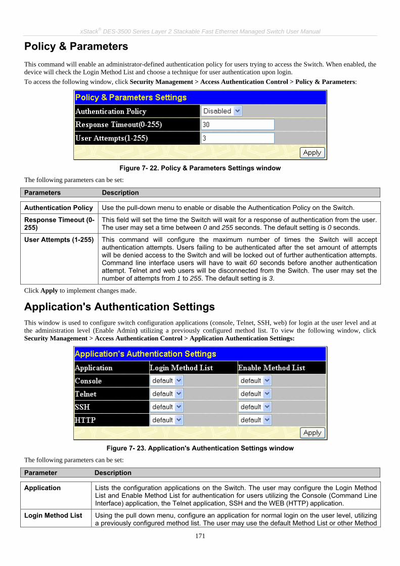
xStack® DES-3500 Series Layer 2 Stackable Fast Ethernet Managed Switch User Manual
171
Policy & Parameters This command will enable an administrator-defined authentication policy for users trying to access the Switch. When enabled, the device will check the Login Method List and choose a technique for user authentication upon login. To access the following window, click Security Management > Access Authentication Control > Policy & Parameters:
Figure 7- 22. Policy & Parameters Settings window
The following parameters can be set:
Parameters Description
Authentication Policy Use the pull-down menu to enable or disable the Authentication Policy on the Switch.
Response Timeout (0-255)
This field will set the time the Switch will wait for a response of authentication from the user. The user may set a time between 0 and 255 seconds. The default setting is 0 seconds.
User Attempts (1-255) This command will configure the maximum number of times the Switch will accept authentication attempts. Users failing to be authenticated after the set amount of attempts will be denied access to the Switch and will be locked out of further authentication attempts. Command line interface users will have to wait 60 seconds before another authentication attempt. Telnet and web users will be disconnected from the Switch. The user may set the number of attempts from 1 to 255. The default setting is 3.
Click Apply to implement changes made.
Application's Authentication Settings This window is used to configure switch configuration applications (console, Telnet, SSH, web) for login at the user level and at the administration level (Enable Admin) utilizing a previously configured method list. To view the following window, click Security Management > Access Authentication Control > Application Authentication Settings:
Figure 7- 23. Application's Authentication Settings window
The following parameters can be set:
Parameter Description
Application Lists the configuration applications on the Switch. The user may configure the Login Method List and Enable Method List for authentication for users utilizing the Console (Command Line Interface) application, the Telnet application, SSH and the WEB (HTTP) application.
Login Method List Using the pull down menu, configure an application for normal login on the user level, utilizing a previously configured method list. The user may use the default Method List or other Method

xStack® DES-3500 Series Layer 2 Stackable Fast Ethernet Managed Switch User Manual
172
List configured by the user. See the Login Method Lists window, in this section, for more information.
Enable Method List Using the pull down menu, configure an application for normal login on the user level, utilizing a previously configured method list. The user may use the default Method List or other Method List configured by the user. See the Enable Method Lists window, in this section, for more information
Click Apply to implement changes made.
Authentication Server Group This window will allow users to set up Authentication Server Groups on the Switch. A server group is a technique used to group TACACS/XTACACS/TACACS+/RADIUS server hosts into user-defined categories for authentication using method lists. The user may define the type of server group by protocol or by previously defined server group. The Switch has three built-in Authentication Server Groups that cannot be removed but can be modified. Up to eight authentications server hosts may be added to any particular group. To view the following window, click Security Management > Access Authentication Control > Authentication Server Group:
Figure 7- 24. Authentication Server Group Settings window
This screen displays the Authentication Server Groups on the Switch. The Switch has four built-in Authentication Server Groups that cannot be removed but can be modified. To modify a particular group, click its hyperlinked Group Name, which will then display the following window.
Figure 7- 25. Add a Server Host to Server Group (xtacas) window
To add an Authentication Server Host to the list, enter its IP address in the IP Address field, choose the protocol associated with the IP address of the Authentication Server Host and click Add to Group to add this Authentication Server Host to the group.
To add a user-defined server group that is not displayed on the screen, click the add button, revealing the following window for the user to configure.

xStack® DES-3500 Series Layer 2 Stackable Fast Ethernet Managed Switch User Manual
173
Figure 7- 26. Authen Server Group Table Add Settings
Enter a group name of up to 15 alphanumeric characters to identify the users Group Name and click Add. The user’s new Group Name will then appear in the Authentication Server Group Settings window as seen below, defined as Trinity.
Figure 7- 27. Authentication Server Group Settings window
The new group may be modified in the same way as the other groups, by clicking the hyperlinked name. Yet, unlike the other groups, the user-defined Group Name can have any combination of Protocol hosts to be in this group. (Ex. TACACS – XTACACS – TACACS+)
NOTE: The user must configure Authentication Server Hosts using the Authentication Server Hosts window before adding hosts to the list. Authentication Server Hosts must be configured for their specific protocol on a remote centralized server before this function can work properly.
NOTE: The three built in server groups can only have server hosts running the same TACACS daemon. TACACS/XTACACS/TACACS+ protocols are separate entities and are not compatible with each other.
Authentication Server Hosts This window will set user-defined Authentication Server Hosts for the TACACS/XTACACS/TACACS+/RADIUS security protocols on the Switch. When a user attempts to access the Switch with Authentication Policy enabled, the Switch will send authentication packets to a remote TACACS/XTACACS/TACACS+/RADIUS server host on a remote host. The TACACS/XTACACS/TACACS+/RADIUS server host will then verify or deny the request and return the appropriate message to the Switch. More than one authentication protocol can be run on the same physical server host but, remember that TACACS/XTACACS/TACACS+/RADIUS are separate entities and are not compatible with each other. The maximum supported number of server hosts is 16. To view the following window, click Security Management > Access Authentication Control > Authentication Server Host:

xStack® DES-3500 Series Layer 2 Stackable Fast Ethernet Managed Switch User Manual
174
Figure 7- 28. Authentication Server Host Settings window
To add an Authentication Server Host, click the Add button, revealing the following window:
Figure 7- 29. Authentication Server Host Settings – Add window
Configure the following parameters to add an Authentication Server Host:
Parameter Description
IP Address The IP address of the remote server host the user wishes to add.
Protocol The protocol used by the server host. The user may choose one of the following:
• TACACS - Enter this parameter if the server host utilizes the TACACS protocol.
• XTACACS - Enter this parameter if the server host utilizes the XTACACS protocol.
• TACACS+ - Enter this parameter if the server host utilizes the TACACS+ protocol.
• RADIUS - Enter this parameter if the server host utilizes the RADIUS protocol.
Port (1-65535) Enter a number between 1 and 65535 to define the virtual port number of the authentication protocol on a server host. The default port number is 49 for TACACS/XTACACS/TACACS+ servers and 1813 for RADIUS servers but the user may set a unique port number for higher security.
Timeout (1-255) Enter the time in seconds the Switch will wait for the server host to reply to an authentication request. The default value is 5 seconds.
Retransmit (1-255) Enter the value in the retransmit field to change how many times the device will resend an authentication request when the TACACS server does not respond. The default value is 2 seconds.
Key Authentication key to be shared with a configured TACACS+ or RADIUS servers only. Specify an alphanumeric string up to 254 characters.
Click Apply to add the server host.

xStack® DES-3500 Series Layer 2 Stackable Fast Ethernet Managed Switch User Manual
175
NOTE: More than one authentication protocol can be run on the same physical server host but, remember that TACACS/XTACACS/TACACS+ are separate entities and are not compatible with each other.
Login Method Lists This command will configure a user-defined or default Login Method List of authentication techniques for users logging on to the Switch. The sequence of techniques implemented in this command will affect the authentication result. For example, if a user enters a sequence of techniques, for example TACACS - XTACACS- local, the Switch will send an authentication request to the first TACACS host in the server group. If no response comes from the server host, the Switch will send an authentication request to the second TACACS host in the server group and so on, until the list is exhausted. At that point, the Switch will restart the same sequence with the following protocol listed, XTACACS. If no authentication takes place using the XTACACS list, the local account database set in the Switch is used to authenticate the user. When the local method is used, the privilege level will be dependant on the local account privilege configured on the Switch. Successful login using any of these techniques will give the user a "User" privilege only. If the user wishes to upgrade his or her status to the administrator level, the user must use the Enable Admin window, in which the user must enter a previously configured password, set by the administrator. (See the Enable Admin part of this section for more detailed information concerning the Enable Admin command.) To view the following window click Security Management > Access Authentication Control > Login Method Lists:
Figure 7- 30. Login Method Lists Settings window
The Switch contains one Method List that is set and cannot be removed, yet can be modified. To delete a Login Method List defined by the user, click the X under the Delete heading corresponding to the entry desired to be deleted. To modify a Login Method List, click on its hyperlinked Method List Name. To configure a new Method List, click the Add button. Both actions will result in the same window to configure:
Figure 7- 31. Login Method List - Edit window (default)

xStack® DES-3500 Series Layer 2 Stackable Fast Ethernet Managed Switch User Manual
176
Figure 7- 32. Login Method List – Add window
To define a Login Method List, set the following parameters and click Apply:
Parameter Description
Method List Name Enter a method list name defined by the user of up to 15 characters.
Method 1, 2, 3, 4 The user may add one, or a combination of up to four of the following authentication methods to this method list:
• tacacs - Adding this parameter will require the user to be authenticated using the TACACS protocol from a remote TACACS server.
• xtacacs - Adding this parameter will require the user to be authenticated using the XTACACS protocol from a remote XTACACS server.
• tacacs+ - Adding this parameter will require the user to be authenticated using the TACACS+ protocol from a remote TACACS+ server.
• radius - Adding this parameter will require the user to be authenticated using the RADIUS protocol from a remote RADIUS server.
• server_group - Adding this parameter will require the user to be authenticated using a user-defined server group previously configured on the Switch.
• local - Adding this parameter will require the user to be authenticated using the local user account database on the Switch.
• none - Adding this parameter will require an authentication to access the Switch.
Enable Method Lists The Enable Method List Settings window is used to set up Method Lists to promote users with user level privileges to Administrator (Admin) level privileges using authentication methods on the Switch. Once a user acquires normal user level privileges on the Switch, he or she must be authenticated by a method on the Switch to gain administrator privileges on the Switch, which is defined by the Administrator. A maximum of eight Enable Method Lists can be implemented on the Switch, one of which is a default Enable Method List. This default Enable Method List cannot be deleted but can be configured. The sequence of methods implemented in this command will affect the authentication result. For example, if a user enters a sequence of methods like TACACS - XTACACS - Local Enable, the Switch will send an authentication request to the first TACACS host in the server group. If no verification is found, the Switch will send an authentication request to the second TACACS host in the server group and so on, until the list is exhausted. At that point, the Switch will restart the same sequence with the following protocol listed, XTACACS. If no authentication takes place using the XTACACS list, the Local Enable password set in the Switch is used to authenticate the user. Successful authentication using any of these methods will give the user an "Admin" privilege.
NOTE: To set the Local Enable Password, see the next section, entitled Local Enable Password.
To view the following table, click Security Management > Access Authentication Control > Enable Method Lists:

xStack® DES-3500 Series Layer 2 Stackable Fast Ethernet Managed Switch User Manual
177
Figure 7- 33. Enable Method List Settings window
To delete an Enable Method List defined by the user, click the X under the Delete heading corresponding to the entry desired to be deleted. To modify an Enable Method List, click on its hyperlinked Method List Name. To configure a Method List, click the Add button. Both actions will result in the same window to configure:
Figure 7- 34. Enable Method List - Edit window
Figure 7- 35. Enable Method List - Add window
To define an Enable Login Method List, set the following parameters and click Apply:
Parameter Description
Method List Name Enter a method list name defined by the user of up to 15 characters.
Method 1, 2, 3, 4 The user may add one, or a combination of up to four of the following authentication methods to this method list:
• local_enable - Adding this parameter will require the user to be authenticated using the local enable password database on the Switch. The user in the next section entitled Local Enable Password must set the local enable password.
• none - Adding this parameter will require an authentication to access the Switch.

xStack® DES-3500 Series Layer 2 Stackable Fast Ethernet Managed Switch User Manual
178
• radius - Adding this parameter will require the user to be authenticated using the RADIUS protocol from a remote RADIUS server.
• tacacs - Adding this parameter will require the user to be authenticated using the TACACS protocol from a remote TACACS server.
• xtacacs - Adding this parameter will require the user to be authenticated using the XTACACS protocol from a remote XTACACS server.
• tacacs+ - Adding this parameter will require the user to be authenticated using the TACACS protocol from a remote TACACS server.
• server_group - Adding a previously configured server group will require the user to be authenticated using a user-defined server group previously configured on the Switch.
Local Enable Password This window will configure the locally enabled password for the Enable Admin command. When a user chooses the "local_enable" method to promote user level privileges to administrator privileges, he or she will be prompted to enter the password configured here that is locally set on the Switch. To view the following window, click Security Management > Access Authentication Control > Local Enable Password:
Figure 7- 36. Configure Local Enable Password window
To set the Local Enable Password, set the following parameters and click Apply.
Parameter Description
Old Local Enabled If a password was previously configured for this entry, enter it here in order to change it to a new password.
New Local Enabled Enter the new password that you wish to set on the Switch to authenticate users attempting to access Administrator Level privileges on the Switch. The user may set a password of up to 15 characters.
Confirm Local Enabled Confirm the new password entered above. Entering a different password here from the one set in the New Local Enabled field will result in a fail message.
Enable Admin The Enable Admin window is for users who have logged on to the Switch at Adminstrator level. Possible authentication methods for this function include TACACS/XTACACS/TACACS+/RADIUS, user defined server groups, local enable (local account on the Switch), or no authentication (none). Because XTACACS and TACACS do not support the enable function, the user must create a special account on the server host, which has the username "enable", and a password configured by the administrator that will support the "enable" function. This function becomes inoperable when the authentication policy is disabled. To view the following window, click Security Management > Access Authentication Control > Enable Admin:

xStack® DES-3500 Series Layer 2 Stackable Fast Ethernet Managed Switch User Manual
179
Figure 7- 37. Enable Admin Screen
If the Authentication Policy is disabled the message in the lower half of the screen will indicate Authentication Policy is disabled!

xStack® DES-3500 Series Layer 2 Stackable Fast Ethernet Managed Switch User Manual
180
Secure Socket Layer (SSL) Secure Sockets Layer or SSL is a security feature that will provide a secure communication path between a host and client through the use of authentication, digital signatures and encryption. These security functions are implemented through the use of a ciphersuite, which is a security string that determines the exact cryptographic parameters, specific encryption algorithms and key sizes to be used for an authentication session and consists of three levels:
1. Key Exchange: The first part of the cyphersuite string specifies the public key algorithm to be used. This switch utilizes the Rivest Shamir Adleman (RSA) public key algorithm and the Digital Signature Algorithm (DSA), specified here as the DHE DSS Diffie-Hellman (DHE) public key algorithm. This is the first authentication process between client and host as they “exchange keys” in looking for a match and therefore authentication to be accepted to negotiate encryptions on the following level.
2. Encryption: The second part of the ciphersuite that includes the encryption used for encrypting the messages sent between client and host. The Switch supports two types of cryptology algorithms:
• Stream Ciphers – There are two types of stream ciphers on the Switch, RC4 with 40-bit keys and RC4 with 128-bit keys. These keys are used to encrypt messages and need to be consistent between client and host for optimal use.
• CBC Block Ciphers – CBC refers to Cipher Block Chaining, which means that a portion of the previously encrypted block of encrypted text is used in the encryption of the current block. The Switch supports the 3DES EDE encryption code defined by the Data Encryption Standard (DES) to create the encrypted text.
3. Hash Algorithm: This part of the ciphersuite allows the user to choose a message digest function which will determine a Message Authentication Code. This Message Authentication Code will be encrypted with a sent message to provide integrity and prevent against replay attacks. The Switch supports two hash algorithms, MD5 (Message Digest 5) and SHA (Secure Hash Algorithm).
These three parameters are uniquely assembled in four choices on the Switch to create a three-layered encryption code for secure communication between the server and the host. The user may implement any one or combination of the ciphersuites available, yet different ciphersuites will affect the security level and the performance of the secured connection. The information included in the ciphersuites is not included with the Switch and requires downloading from a third source in a file form called a certificate. This function of the Switch cannot be executed without the presence and implementation of the certificate file and can be downloaded to the Switch by utilizing a TFTP server. The Switch supports SSLv3 and TLSv1. Other versions of SSL may not be compatible with this Switch and may cause problems upon authentication and transfer of messages from client to host.
Download Certificate
Figure 7- 38. Download Certificate window
To download certificates, set the following parameters and click Apply.
Parameter Description
Certificate Type Enter the type of certificate to be downloaded. This type refers to the server responsible for issuing certificates. This field has been limited to local for this firmware release.
Server IP Enter the IP address of the TFTP server where the certificate files are located.
Certificate File Name Enter the path and the filename of the certificate file to download. This file must have a .der extension. (Ex. c:/cert.der)
Key File Name Enter the path and the filename of the key file to download. This file must have a .der extension (Ex. c:/pkey.der)
This window is used to download a certificate file for the SSL function on the Switch from a TFTP server. The certificate file is a data record used for authenticating devices on the network. It contains information on the owner, keys for authentication and digital signatures. Both the server and the client must have consistent certificate files for optimal use of the SSL function. The Switch only supports certificate files with .der file extensions. The Switch is shipped with a certificate pre-loaded though the user may need to download more, depending on user circumstances. To view the following window, click Configuration > Secure Socket Layer (SSL) > Download Certificate:

xStack® DES-3500 Series Layer 2 Stackable Fast Ethernet Managed Switch User Manual
181
Configuration This window will allow the user to enable SSL on the Switch and implement any one or combination of listed ciphersuites on the Switch. A ciphersuite is a security string that determines the exact cryptographic parameters, specific encryption algorithms and key sizes to be used for an authentication session. The Switch possesses four possible ciphersuites for the SSL function, which are all enabled by default. To utilize a particular ciphersuite, disable the unwanted ciphersuites, leaving the desired one for authentication. When the SSL function has been enabled, the web will become disabled. To manage the Switch through the web based management while utilizing the SSL function, the web browser must support SSL encryption and the header of the URL must begin with https://. (Ex. https://10.90.90.90) Any other method will result in an error and no access can be authorized for the web-based management. To view the following window, click Configuration > Secure Socket Layer (SSL) > Configuration:
Figure 7- 39. Ciphersuite window
To set up the SSL function on the Switch, configure the following parameters and click Apply.
Parameter Description
SSL Status Use the pull-down menu to enable or disable the SSL status on the switch. The default is Disabled.
Cache Timeout(60-86400 sec)
Enter the Cache Timeout in seconds the default value is 600 seconds.
RSA with RC4 128 MD5
This ciphersuite combines the RSA key exchange, stream cipher RC4 encryption with 128-bit keys and the MD5 Hash Algorithm. Use the pull-down menu to enable or disable this ciphersuite. This field is Enabled by default.
RSA with 3DES EDE CBC SHA
This ciphersuite combines the RSA key exchange, CBC Block Cipher 3DES_EDE encryption and the SHA Hash Algorithm. Use the pull-down menu to enable or disable this ciphersuite. This field is Enabled by default.
DHS DSS with 3DES EDE CBC SHA
This ciphersuite combines the DSA Diffie Hellman key exchange, CBC Block Cipher 3DES_EDE encryption and SHA Hash Algorithm. Use the pull-down menu to enable or disable this ciphersuite. This field is Enabled by default.
RSA EXPORT with RC4 40 MD5
This ciphersuite combines the RSA Export key exchange and stream cipher RC4 encryption with 40-bit keys. Use the pull-down menu to enable or disable this ciphersuite. This field is Enabled by default.
NOTE: Certain implementations concerning the function and configuration of SSL are not available on the web-based management of this Switch and need to be configured using the command line interface. For more information on SSL and its functions, see the DES-3500 Series Command Line Reference Manual, located on the documentation CD of this product.

xStack® DES-3500 Series Layer 2 Stackable Fast Ethernet Managed Switch User Manual
182
NOTE: Enabling the SSL command will disable the web-based switch management. To log on to the Switch again, the header of the URL must begin with https://. Entering anything else into the address field of the web browser will result in an error and no authentication will be granted.
Secure Shell (SSH) SSH is an abbreviation of Secure Shell, which is a program allowing secure remote login and secure network services over an insecure network. It allows a secure login to remote host computers, a safe method of executing commands on a remote end node, and will provide secure encrypted and authenticated communication between two non-trusted hosts. SSH, with its array of unmatched security features is an essential tool in today’s networking environment. It is a powerful guardian against numerous existing security hazards that now threaten network communications. The steps required to use the SSH protocol for secure communication between a remote PC (the SSH client) and the Switch (the SSH server) are as follows:
1. Create a user account with admin-level access using the User Accounts window in the Security Management folder. This is identical to creating any other admin-level User Account on the Switch, including specifying a password. This password is used to logon to the Switch, once a secure communication path has been established using the SSH protocol.
2. Configure the User Account to use a specified authorization method to identify users that are allowed to establish SSH connections with the Switch using the SSH User Authentication window. There are three choices as to the method SSH will use to authorize the user, which are Host Based, Password and Public Key.
3. Configure the encryption algorithm that SSH will use to encrypt and decrypt messages sent between the SSH client and the SSH server, using the SSH Algorithm window.
4. Finally, enable SSH on the Switch using the SSH Configuration window. After completing the preceding steps, a SSH Client on a remote PC can be configured to manage the Switch using a secure, in band connection.
SSH Configuration The following window is used to configure and view settings for the SSH server and can be opened by clicking Security Management > Secure Shell (SSH) > SSH Configuration:

xStack® DES-3500 Series Layer 2 Stackable Fast Ethernet Managed Switch User Manual
183
Figure 7- 40. Current SSH Configuration Settings
To configure the SSH server on the Switch, modify the following parameters and click Apply:
Parameter Description
SSH Server Status Use the pull-down menu to enable or disable SSH on the Switch. The default is Disabled.
Max Session (1-8) Enter a value between 1 and 8 to set the number of users that may simultaneously access the Switch. The default setting is 8.
Time Out (120-600) Allows the user to set the connection timeout. The use may set a time between 120 and 600 seconds. The default setting is 300 seconds.
Auth. Fail (2-20) Allows the Administrator to set the maximum number of attempts that a user may try to log on to the SSH Server utilizing the SSH authentication. After the maximum number of attempts has been exceeded, the Switch will be disconnected and the user must reconnect to the Switch to attempt another login. The number of maximum attempts may be set between 2 and 20. The default setting is 2.
Session Rekeying Using the pull-down menu uses this field to set the time period that the Switch will change the security shell encryptions. The available options are Never, 10 min, 30 min, and 60 min. The default setting is Never.
Port(1-65535) Enter the ports for the SSH Configuration.
SSH Algorithm The SSH Algorithm window allows the configuration of the desired types of SSH algorithms used for authentication encryption. There are four categories of algorithms listed and specific algorithms of each may be enabled or disabled by using their corresponding pull-down menus. All algorithms are enabled by default. To open the following window, click Security Management > Secure Shell (SSH) > SSH Algorithm:

xStack® DES-3500 Series Layer 2 Stackable Fast Ethernet Managed Switch User Manual
184
Figure 7- 41. Encryption Algorithm window
The following algorithms may be set:
Parameter Description
Encryption Algorithm
3DES-CBC Use the pull-down to enable or disable the Triple Data Encryption Standard encryption algorithm with Cipher Block Chaining. The default is Enabled.
Blow-fish CBC Use the pull-down to enable or disable the Blowfish encryption algorithm with Cipher Block Chaining. The default is Enabled.
AES128-CBC Use the pull-down to enable or disable the Advanced Encryption Standard AES128 encryption algorithm with Cipher Block Chaining. The default is Enabled.
AES192-CBC Use the pull-down to enable or disable the Advanced Encryption Standard AES192 encryption algorithm with Cipher Block Chaining. The default is Enabled.
AES256-CBC Use the pull-down to enable or disable the Advanced Encryption Standard AES-256 encryption algorithm with Cipher Block Chaining. The default is Enabled.
ARC4 Use the pull-down to enable or disable the Arcfour encryption algorithm with Cipher Block Chaining. The default is Enabled.
Cast128-CBC Use the pull-down to enable or disable the Cast128 encryption algorithm with Cipher Block Chaining. The default is Enabled.
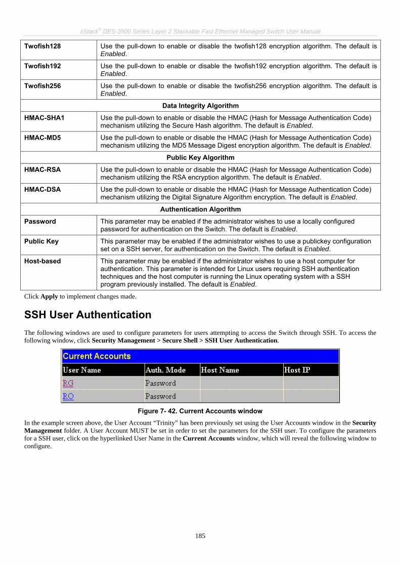
xStack® DES-3500 Series Layer 2 Stackable Fast Ethernet Managed Switch User Manual
185
Twofish128 Use the pull-down to enable or disable the twofish128 encryption algorithm. The default is Enabled.
Twofish192 Use the pull-down to enable or disable the twofish192 encryption algorithm. The default is Enabled.
Twofish256 Use the pull-down to enable or disable the twofish256 encryption algorithm. The default is Enabled.
Data Integrity Algorithm
HMAC-SHA1 Use the pull-down to enable or disable the HMAC (Hash for Message Authentication Code) mechanism utilizing the Secure Hash algorithm. The default is Enabled.
HMAC-MD5 Use the pull-down to enable or disable the HMAC (Hash for Message Authentication Code) mechanism utilizing the MD5 Message Digest encryption algorithm. The default is Enabled.
Public Key Algorithm
HMAC-RSA Use the pull-down to enable or disable the HMAC (Hash for Message Authentication Code) mechanism utilizing the RSA encryption algorithm. The default is Enabled.
HMAC-DSA Use the pull-down to enable or disable the HMAC (Hash for Message Authentication Code) mechanism utilizing the Digital Signature Algorithm encryption. The default is Enabled.
Authentication Algorithm
Password This parameter may be enabled if the administrator wishes to use a locally configured password for authentication on the Switch. The default is Enabled.
Public Key This parameter may be enabled if the administrator wishes to use a publickey configuration set on a SSH server, for authentication on the Switch. The default is Enabled.
Host-based This parameter may be enabled if the administrator wishes to use a host computer for authentication. This parameter is intended for Linux users requiring SSH authentication techniques and the host computer is running the Linux operating system with a SSH program previously installed. The default is Enabled.
Click Apply to implement changes made.
SSH User Authentication The following windows are used to configure parameters for users attempting to access the Switch through SSH. To access the following window, click Security Management > Secure Shell > SSH User Authentication.
Figure 7- 42. Current Accounts window
In the example screen above, the User Account “Trinity” has been previously set using the User Accounts window in the Security Management folder. A User Account MUST be set in order to set the parameters for the SSH user. To configure the parameters for a SSH user, click on the hyperlinked User Name in the Current Accounts window, which will reveal the following window to configure.
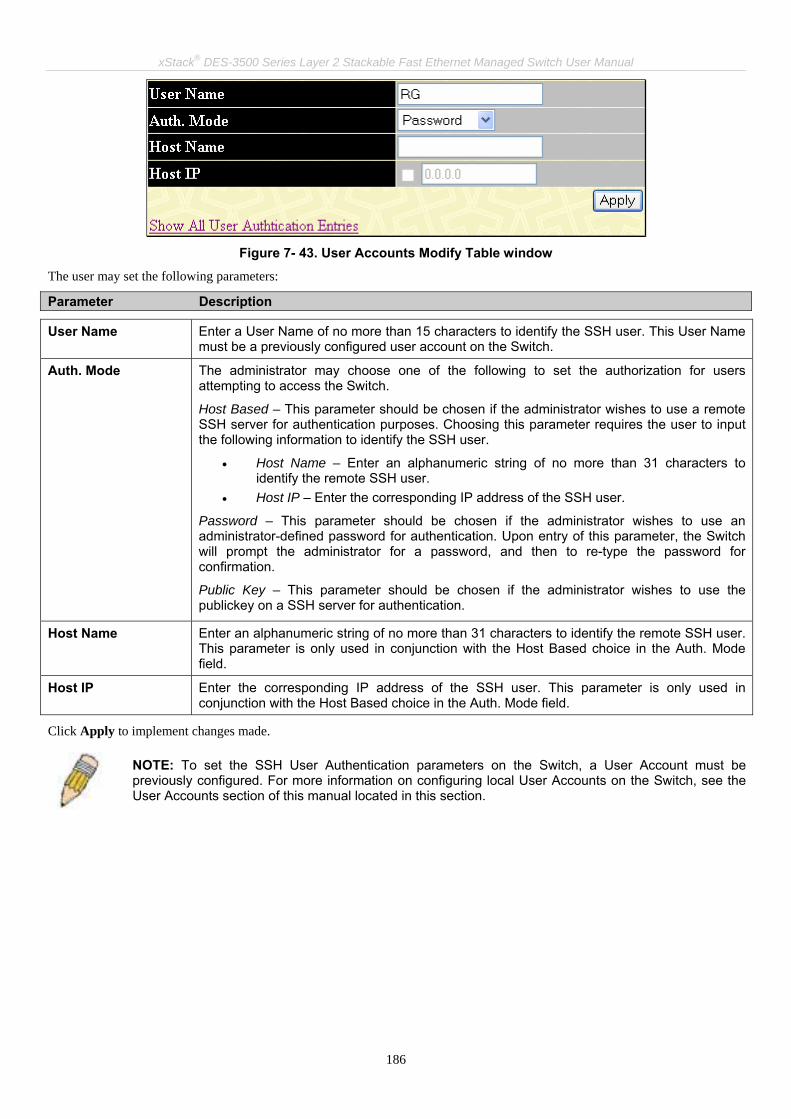
xStack® DES-3500 Series Layer 2 Stackable Fast Ethernet Managed Switch User Manual
186
Figure 7- 43. User Accounts Modify Table window
The user may set the following parameters:
Parameter Description
User Name Enter a User Name of no more than 15 characters to identify the SSH user. This User Name must be a previously configured user account on the Switch.
Auth. Mode The administrator may choose one of the following to set the authorization for users attempting to access the Switch.
Host Based – This parameter should be chosen if the administrator wishes to use a remote SSH server for authentication purposes. Choosing this parameter requires the user to input the following information to identify the SSH user.
• Host Name – Enter an alphanumeric string of no more than 31 characters to identify the remote SSH user.
• Host IP – Enter the corresponding IP address of the SSH user.
Password – This parameter should be chosen if the administrator wishes to use an administrator-defined password for authentication. Upon entry of this parameter, the Switch will prompt the administrator for a password, and then to re-type the password for confirmation.
Public Key – This parameter should be chosen if the administrator wishes to use the publickey on a SSH server for authentication.
Host Name Enter an alphanumeric string of no more than 31 characters to identify the remote SSH user. This parameter is only used in conjunction with the Host Based choice in the Auth. Mode field.
Host IP Enter the corresponding IP address of the SSH user. This parameter is only used in conjunction with the Host Based choice in the Auth. Mode field.
Click Apply to implement changes made.
NOTE: To set the SSH User Authentication parameters on the Switch, a User Account must be previously configured. For more information on configuring local User Accounts on the Switch, see the User Accounts section of this manual located in this section.
xStack® DES-3500 Series Layer 2 Stackable Fast Ethernet Managed Switch User Manual
187
SNMP Manager SNMP Settings Simple Network Management Protocol (SNMP) is an OSI Layer 7 (Application Layer) designed specifically for managing and monitoring network devices. SNMP enables network management stations to read and modify the settings of gateways, routers, switches, and other network devices. Use SNMP to configure system features for proper operation, monitor performance and detect potential problems in the Switch, switch group or network. Managed devices that support SNMP include software (referred to as an agent), which runs locally on the device. A defined set of variables (managed objects) is maintained by the SNMP agent and used to manage the device. These objects are defined in a Management Information Base (MIB), which provides a standard presentation of the information controlled by the on-board SNMP agent. SNMP defines both the format of the MIB specifications and the protocol used to access this information over the network. The DES-3500 Series switches support the SNMP versions 1, 2c, and 3. You can specify which version of the SNMP you want to use to monitor and control the Switch. The three versions of SNMP vary in the level of security provided between the management station and the network device. In SNMP v.1 and v.2, user authentication is accomplished using 'community strings', which function like passwords. The remote user SNMP application and the Switch SNMP must use the same community string. SNMP packets from any station that has not been authenticated are ignored (dropped). The default community strings for the Switch used for SNMP v.1 and v.2 management access are:
• public - Allows authorized management stations to retrieve MIB objects. • private - Allows authorized management stations to retrieve and modify MIB objects.
SNMPv3 uses a more sophisticated authentication process that is separated into two parts. The first part is to maintain a list of users and their attributes that are allowed to act as SNMP managers. The second part describes what each user on that list can do as an SNMP manager. The Switch allows groups of users to be listed and configured with a shared set of privileges. The SNMP version may also be set for a listed group of SNMP managers. Thus, you may create a group of SNMP managers that are allowed to view read-only information or receive traps using SNMPv1 while assigning a higher level of security to another group, granting read/write privi-leges using SNMPv3. Using SNMPv3 individual users or groups of SNMP managers can be allowed to perform or be restricted from performing specific SNMP management functions. The functions allowed or restricted are defined using the Object Identifier (OID) associated with a specific MIB. An additional layer of security is available for SNMPv3 in that SNMP messages may be encrypted. To read more about how to configure SNMPv3 settings for the Switch read the next section.
Traps Traps are messages that alert network personnel of events that occur on the Switch. The events can be as serious as a reboot (someone accidentally turned OFF the Switch), or less serious like a port status change. The Switch generates traps and sends them to the trap recipient (or network manager). Typical traps include trap messages for Authentication Failure, Topology Change and Broadcast\Multicast Storm.
MIBs The Switch in the Management Information Base (MIB) stores management and counter information. The Switch uses the standard MIB-II Management Information Base module. Consequently, values for MIB objects can be retrieved from any SNMP-based network management software. In addition to the standard MIB-II, the Switch also supports its own proprietary enterprise MIB as an extended Management Information Base. Specifying the MIB Object Identifier may also retrieve the proprietary MIB. MIB values can be either read-only or read-write. The DES-3500 Series switches incorporate a flexible SNMP management for the switching environment. SNMP management can be customized to suit the needs of the networks and the preferences of the network administrator. Use the SNMP V3 menus to select the SNMP version used for specific tasks. The DES-3500 Series switches support the Simple Network Management Protocol (SNMP) versions 1, 2c, and 3. The administrator can specify the SNMP version used to monitor and control the Switch. The three versions of SNMP vary in the level of security provided between the management station and the network device. SNMP settings are configured using the menus located on the SNMP V3 folder of the web manager. Workstations on the network that are allowed SNMP privileged access to the Switch can be restricted with the Management Station IP Address menu.

xStack® DES-3500 Series Layer 2 Stackable Fast Ethernet Managed Switch User Manual
188
SNMP User Table The SNMP User Table displays all of the SNMP User's currently configured on the Switch. To view this window click, Security Management > SNMP Manager > SNMP User Table.
Figure 7- 44. SNMP User Table window
To delete an existing SNMP User Table entry, click the button under the Delete heading corresponding to the entry you wish to delete. To display the detailed entry for a given user, click on the hyperlinked User Name. This will open the SNMP User Table Display window, as shown below.
Figure 7- 45. SNMP User Table Display window
The following parameters are displayed:
Parameter Description
User Name An alphanumeric string of up to 32 characters. This is used to identify the SNMP users.
Group Name This name is used to specify the SNMP group created can request SNMP messages.
SNMP Version V1 - Indicates that SNMP version 1 is in use. V2 - Indicates that SNMP version 2 is in use. V3 - Indicates that SNMP version 3 is in use.
Auth-Protocol None - Indicates that no authorization protocol is in use. MD5 - Indicates that the HMAC-MD5-96 authentication level will be used. SHA - Indicates that the HMAC-SHA authentication protocol will be used.
Priv-Protocol None - Indicates that no authorization protocol is in use. DES - Indicates that DES 56-bit encryption is in use based on the CBC-DES (DES-56) standard.
To return to the SNMP User Table, click the Show All SNMP User Table Entries link. To add a new entry to the SNMP User Table Configuration window, click on the Add button on the SNMP User Table window. This will open the SNMP User Table Configuration window, as shown below.

xStack® DES-3500 Series Layer 2 Stackable Fast Ethernet Managed Switch User Manual
189
Figure 7- 46. SNMP User Table Configuration window
The following parameters can set:
Parameter Description
User Name Enter an alphanumeric string of up to 32 characters. This is used to identify the SNMP user.
Group Name This name is used to specify the SNMP group created can request SNMP messages.
SNMP Version V1 - Specifies that SNMP version 1 will be used. V2 - Specifies that SNMP version 2 will be used. V3 - Specifies that SNMP version 3 will be used.
Auth-Protocol MD5 - Specifies that the HMAC-MD5-96 authentication level will be used. This field is only operable when V3 is selected in the SNMP Version field and the Encryption field has been checked. This field will require the user to enter a password. SHA - Specifies that the HMAC-SHA authentication protocol will be used. This field is only operable when V3 is selected in the SNMP Version field and the Encryption field has been checked. This field will require the user to enter a password.
Priv-Protocol None - Specifies that no authorization protocol is in use. DES - Specifies that DES 56-bit encryption is in use, based on the CBC-DES (DES-56) standard. This field is only operable when V3 is selected in the SNMP Version field and the Encryption field has been checked. This field will require the user to enter a password between 8 and 16 alphanumeric characters.
Encrypted Checking the corresponding box will enable encryption for SNMP V3 and is only operable in SNMP V3 mode.
To implement changes made, click Apply. To return to the SNMP User Table, click the Show All SNMP User Table Entries link.

xStack® DES-3500 Series Layer 2 Stackable Fast Ethernet Managed Switch User Manual
190
SNMP View Table The SNMP View Table is used to assign views to community strings that define which MIB objects can be accessed by a remote SNMP manager. To view this window click, Security Management > SNMP Manager > SNMP View Table.
Figure 7- 47. SNMP View Table window
To delete an existing SNMP View Table entry, click the button in the Delete column corresponding to the entry you wish to delete. To create a new entry, click the Add button and a separate window will appear.
Figure 7- 48. SNMP View Table Configuration window
The SNMP Group created with this table maps SNMP users (identified in the SNMP User Table) to the views created in the previous window. The following parameters can set:
Parameter Description
View Name Type an alphanumeric string of up to 32 characters. This is used to identify the new SNMP view being created.
Subtree OID Type the Object Identifier (OID) Subtree for the view. The OID identifies an object tree (MIB tree) that will be included or excluded from access by an SNMP manager.
View Type Select Included to include this object in the list of objects that an SNMP manager can access. Select Excluded to exclude this object from the list of objects that an SNMP manager can access.
To implement your new settings, click Apply. To return to the SNMP View Table, click the Show All SNMP View Table Entries link.

xStack® DES-3500 Series Layer 2 Stackable Fast Ethernet Managed Switch User Manual
191
SNMP Group Table An SNMP Group created with this table maps SNMP users (identified in the SNMP User Table) to the views created in the previous menu. To view this window click, Security Management > SNMP Manager > SNMP Group Table.
Figure 7- 49. SNMP Group Table window
To delete an existing SNMP Group Table entry, click the corresponding button under the Delete heading. To display the current settings for an existing SNMP Group Table entry, click the hyperlink for the entry under the Group Name.
Figure 7- 50. SNMP Group Table Display window
To add a new entry to the Switch's SNMP Group Table, click the Add button in the upper left-hand corner of the SNMP Group Table window. This will open the SNMP Group Table Configuration window, as shown below.

xStack® DES-3500 Series Layer 2 Stackable Fast Ethernet Managed Switch User Manual
192
Figure 7- 51. SNMP Group Table Configuration window
The following parameters can set:
Parameter Description
Group Name Type an alphanumeric string of up to 32 characters. This is used to identify the new SNMP group of SNMP users.
Read View Name Specify a SNMP group name for users that are allowed SNMP read privileges to the Switch's SNMP agent. The view name must exist in the SNMP View Table.
Write View Name Specify a SNMP group name for users that are allowed SNMP write privileges to the Switch's SNMP agent. The view name must exist in the SNMP View Table.
Notify View Name Specify a SNMP group name for users that can receive SNMP trap messages generated by the Switch's SNMP agent. The view name must exist in the SNMP View Table.
Security Model SNMPv1 - Specifies that SNMP version 1 will be used. SNMPv2 - Specifies that SNMP version 2c will be used. The SNMPv2 supports both centralized and distributed network management strategies. It includes improvements in the Structure of Management Information (SMI) and adds some security features. SNMPv3 - Specifies that the SNMP version 3 will be used. SNMPv3 provides secure access to devices through a combination of authentication and encrypting packets over the network.
Security Level The Security Level settings only apply to SNMPv3. NoAuthNoPriv - Specifies that there will be no authorization and no encryption of packets sent between the Switch and a remote SNMP manager. AuthNoPriv - Specifies that authorization will be required, but there will be no encryption of packets sent between the Switch and a remote SNMP manager. AuthPriv - Specifies that authorization will be required, and that packets sent between the Switch and a remote SNMP manger will be encrypted.
To implement your new settings, click Apply. To return to the SNMP Group Table, click the Show All SNMP Group Table Entries link.
SNMP Community Table Use this table to create an SNMP community string to define the relationship between the SNMP manager and an agent. The community string acts like a password to permit access to the agent on the Switch. One or more of the following characteristics can be associated with the community string:
• An Access List of IP addresses of SNMP managers that are permitted to use the community string to gain access to the Switch's SNMP agent.
• Any MIB view that defines the subset of all MIB objects will be accessible to the SNMP community.
• Read/write or read-only level permission for the MIB objects accessible to the SNMP community.

xStack® DES-3500 Series Layer 2 Stackable Fast Ethernet Managed Switch User Manual
193
To configure SNMP Community entries, open the SNMP Manager folder, located in the Security Management folder, and click the SNMP Community Table link, which will open the following window:
Figure 7- 52. SNMP Community Table Configuration window
The following parameters can set:
Parameter Description
Community Name Type an alphanumeric string of up to 32 characters that is used to identify members of an SNMP community. This string is used like a password to give remote SNMP managers access to MIB objects in the Switch's SNMP agent.
View Name Type an alphanumeric string of up to 32 characters that is used to identify the group of MIB objects that a remote SNMP manager is allowed to access on the Switch. The view name must exist in the SNMP View Table.
Access Right Read Only - Specifies that SNMP community members using the community string created can only read the contents of the MIBs on the Switch. Read Write - Specifies that SNMP community members using the community string created can read from, and write to the contents of the MIBs on the Switch.
To implement the new settings, click Apply. To delete an entry from the SNMP Community Table, click the under the Delete heading, corresponding to the entry you wish to delete.
SNMP Host Table Use the SNMP Host Table window to set up SNMP trap recipients. To open this window click, Security Management > SNMP Manager > SNMP Host Table.
To delete an existing SNMP Host Table entry, click the corresponding button under the Delete heading. To display the current settings for an existing SNMP Host Table entry, click the blue link for the entry under the Host IP Address heading.
Figure 7- 53. SNMP Host Table window
To add a new entry to the Switch's SNMP Host Table, click the Add button in the upper left-hand corner of the window. This will open the SNMP Host Table Configuration window, as shown below.

xStack® DES-3500 Series Layer 2 Stackable Fast Ethernet Managed Switch User Manual
194
Figure 7- 54. SNMP Host Table Configuration window
The following parameters can set:
Parameter Description
Host IP Address Type the IP address of the remote management station that will serve as the SNMP host for the Switch.
SNMP Version V1 - To specifies that SNMP version 1 will be used. V2 - To specify that SNMP version 2 will be used. V3-NoAuth-NoPriv - To specify that the SNMP version 3 will be used, with a NoAuth-NoPriv security level. V3-Auth-NoPriv - To specify that the SNMP version 3 will be used, with an Auth-NoPriv security level. V3-Auth-Priv - To specify that the SNMP version 3 will be used, with an Auth-Priv security level.
Community String/SNMP V3 User Name
Type in the community string or SNMP V3 user name as appropriate.
To implement your new settings, click Apply. To return to the SNMP Host Table, click the Show All SNMP Host Table Entries link.
SNMP Engine ID The Engine ID is a unique identifier used for SNMP V3 implementations. This is an alphanumeric string used to identify the SNMP engine on the Switch. To display the Switch's SNMP Engine ID, click Security Management > SNMP Manger > SNMP Engine ID. This will open the SNMP Engine ID Configuration window, as shown below.
Figure 7- 55. SNMP Engine ID Configuration window
To change the Engine ID, type the new Engine ID in the space provided and click the Apply button.
SNMP Trap The following window is used to enable or disable trap settings for the SNMP function on the Switch. To view this window for configuration, click Security Management > SNMP Manger > SNMP Trap.

xStack® DES-3500 Series Layer 2 Stackable Fast Ethernet Managed Switch User Manual
195
Figure 7- 56. SNMP Trap Global Settings window
To enable or disable the SNMP Trap State and/or the Authenticate Traps State, use the corresponding pull-down menu to change and click Apply.

xStack® DES-3500 Series Layer 2 Stackable Fast Ethernet Managed Switch User Manual
196
Safeguard Engine Periodically, malicious hosts on the network will attack the Switch by utilizing packet flooding (ARP Storm) or other methods. These attacks may increase the Safeguard Engine beyond its capability. To alleviate this problem, the Safeguard Engine function was added to the Switch’s software. The Safeguard Engine can help the overall operability of the Switch by minimizing the workload of the Switch while the attack is ongoing, thus making it capable to forward essential packets over its network in a limited bandwidth. When the Switch either (a) receives too many packets to process or (b) exerts too much memory, it will enter an Exhausted mode. When in this mode, the Switch will drop all ARP and IP broadcast packets for a calculated time interval. Every five seconds, the Switch will check to see if there are too many packets flooding the Switch. If the threshold has been crossed, the Switch will initially stop all ingress ARP and IP broadcast packets for five seconds. After another five-second checking interval arrives, the Switch will again check the ingress flow of packets. If the flooding has stopped, the Switch will again begin accepting all packets. Yet, if the checking shows that there continues to be too many packets flooding the Switch, it will stop accepting all ARP and IP broadcast packets for double the time of the previous stop period. This doubling of time for stopping ingress ARP and IP broadcast packets will continue until the maximum time has been reached, which is 320 seconds and every stop from this point until a return to normal ingress flow would be 320 seconds. For a better understanding, examine the following example of the Safeguard Engine.
Figure 7- 57. Safeguard Engine example
For every consecutive checking interval that reveals a packet flooding issue, the Switch will double the time it will discard ingress ARP and IP broadcast packets. In the example above, the Switch doubled the time for dropping ARP and IP broadcast packets when consecutive flooding issues were detected at 5 second intervals. (First stop = 5 seconds, second stop = 10 seconds, third stop = 20 seconds) Once the flooding is no longer detected, the wait period for dropping ARP and IP broadcast packets will return to 5 seconds and the process will resume.
Once in Exhausted mode, the packet flow will decrease by half of the level that caused the Switch to enter Exhausted mode. After the packet flow has stabilized, the rate will initially increase by 25% and then return to a normal packet flow. To configure the Safeguard Engine for the Switch, click Security > Safeguard Engine > which will open the following window.

xStack® DES-3500 Series Layer 2 Stackable Fast Ethernet Managed Switch User Manual
197
Figure 7- 58. Safeguard Engine window
To configure the Switch’s Safeguard Engine, change the State to Enabled. To configure the parameters for the Safeguard Engine, click the Advanced Settings button which will alter the previous screen to look like this:
Figure 7- 59. Safeguard Engine window - Advanced Settings
To set the Safeguard Engine for the Switch, complete the following fields:
Parameter Description
State Toggle the State field to either Enabled or Disabled for the Safeguard Engine of the Switch.
Rising Threshold Used to configure the acceptable level of CPU utilization before the Safeguard Engine mechanism is enabled. Once the CPU utilization reaches this percentage level, the Switch will move into the Exhausted state.
Falling Threshold Used to configure the acceptable level of CPU utilization as a percentage, where the Switch leaves the Exhausted state and returns to normal mode.
Trap/log Use the pull-down menu to enable or disable the sending of messages to the device’s SNMP agent and switch log once the Safeguard Engine has been activated by a high CPU utilization rate.

xStack® DES-3500 Series Layer 2 Stackable Fast Ethernet Managed Switch User Manual
198
Filter DHCP Server Screening Setting Due to this function allow you not only to restrict all DHCP Server packets but also to receive any specified DHCP server packet by any specified DHCP client, it is useful when one or more than one DHCP servers are present on the network and both provide DHCP services to different distinct groups of clients. Enabling the DHCP filter in the first time will create both an access profile and access rule per port, then creat other access rules following. These rules are used to block all DHCP server packets. Similarly, addition of a permit DHCP entry will create one access profile and create one access rule only in the first time where DHCP client MAC address is the client MAC address, and the Source IP address is the same as the DHCP server’s IP address (UDP port number 67) that set in the DHCP Client Screening Setting window. These rules are used to permit the DHCP server packets with specific fileds, which the user configured. To view this window, click Security Management > Filter > DHCP Server Screening Settings. When DHCP Server filter function is enabled in DHCP Server Screening Setting window, all DHCP Server packets will be filtered from a specific port.
Figure 7- 60. DHCP Server Screening Setting window

xStack® DES-3500 Series Layer 2 Stackable Fast Ethernet Managed Switch User Manual
199
The parameters of DHCP Server Screening window are described as below:
Parameter Description
From/To These two drop-down menus allow you to select a range of ports to which the filter settings will be applied.
State Enable or disable DHCP Server filter for the ports selected using the pull-down menu. The default setting is Disable.
To implement the new settings, click Apply. Then the current configuration will be displayed in the DHCP Server Screening Status table.
DHCP Client Filtering Setting This window allows you to create entries for specific Server IP address and Client MAC address binding by port-based. Be aware that the DHCP Server filter function must be enabled in DHCP Server Screening Setting window first. Once all setting is done, all DHCP Server packets will be filtered from a specific port except those that meet the Server IP Address and Client MAC Address binding set in the following DHCP Client Screening Setting window. To view this window, click Security Management > Filter > DHCP Client Filtering Settings.
Figure 7- 61. DHCP Client Filtering Setting window
The parameters of the above window are described as below:
Parameter Description
Server IP Address Enter IP address of the Server.
Client MAC Address Enter MAC address of the Client.
All Ports Check it to select all port of the Switch.
Ports Check the corresponding boxes for the port(s) you wish to apply the settings.
Click Apply to implement the new settings or Modify to renew the settings. Then the DHCP Client Filtering Status table will show up the current status for all existing entries. To delete any existing entry, click the corresponding button under the Delete heading.
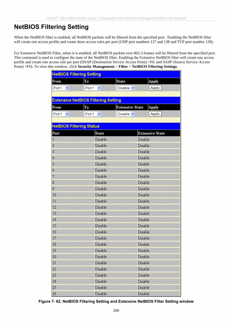
xStack® DES-3500 Series Layer 2 Stackable Fast Ethernet Managed Switch User Manual
200
NetBIOS Filtering Setting When the NetBIOS filter is enabled, all NetBIOS packets will be filtered from the specified port. Enabling the NetBIOS filter will create one access profile and create three access rules per port (UDP port numbers 137 and 138 and TCP port number 139). For Extensive NetBIOS Filter, when it is enabled, all NetBIOS packets over 802.3 frames will be filtered from the specified port. This command is used to configure the state of the NetBIOS filter. Enabling the Extensive NetBIOS filter will create one access profile and create one access rule per port (DSAP (Destination Service Access Point) =F0, and SASP (Source Service Access Point) =F0). To view this window, click Security Management > Filter > NetBIOS Filtering Settings.
Figure 7- 62. NetBIOS Filtering Setting and Extensive NetBIOS Filter Setting window

xStack® DES-3500 Series Layer 2 Stackable Fast Ethernet Managed Switch User Manual
201
The parameters are described as below:
Parameter Description
From/To These two drop-down menus allow you to select a range of ports to which the filter settings will be applied.
State Enable or disable NetBIOS filter for the ports selected using the pull-down menu. The default setting is Disable.
Extensive State Enable or disable Extensive NetBIOS filter for the ports selected using the pull-down menu. The default setting is Disable.
To implement the new settings, click Apply. Then the current configuration will be displayed in the NetBIOS Filtering Status table.

xStack® DES-3500 Series Layer 2 Stackable Fast Ethernet Managed Switch User Manual
202
CPU Filtering Settings
Figure 7- 63. CPU Filtering Settings window
ARP Spoofing Prevention ARP spoofing, also known as ARP poisoning, is a method to attack an Ethernet network which may allow an attacker to sniff data frames on a LAN, modify the traffic, or stop the traffic altogether (known as a Denial of Service – Dos attack). The principle of ARP spoofing is to send the fakes, or spoofed ARP messages to an Ethernet network. Generally, the aim is to associate the attacker’s or random MAC address with the IP address of another node (such as the default gateway). Any traffic meant for that IP address would be mistakenly re-directed to the node specified by the attacker.
This table is used to adjust the CPU Filtering Settings. This table allows the user to Enable or Disable a number of settings for different ports on the Switch including; RIP, OSPF, VRRP, PIM, DVMRP or IGMP Query. Select the settings you wish to change for individual ports or port ranges and click Apply the changes can be viewed in the CPU Filtering Status – L3 Control Packet table on the lower have of the screen. To view this window, click Security Management > Filter > CPU Filtering Settings.
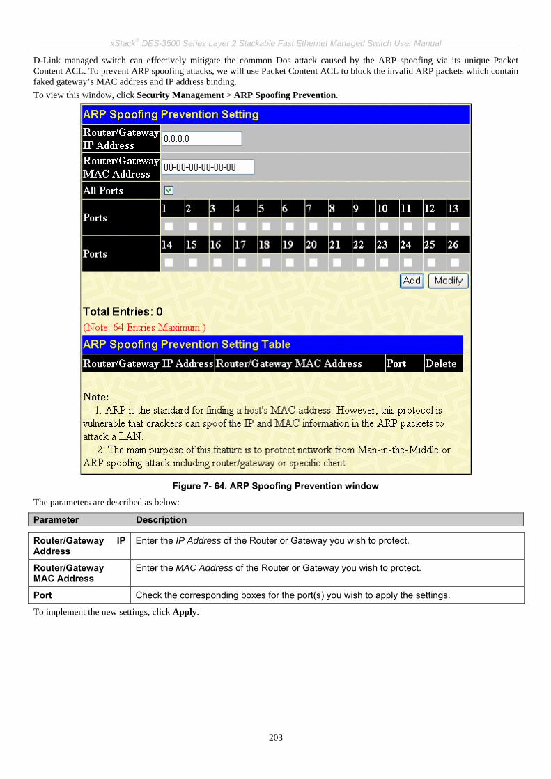
xStack® DES-3500 Series Layer 2 Stackable Fast Ethernet Managed Switch User Manual
203
D-Link managed switch can effectively mitigate the common Dos attack caused by the ARP spoofing via its unique Packet Content ACL. To prevent ARP spoofing attacks, we will use Packet Content ACL to block the invalid ARP packets which contain faked gateway’s MAC address and IP address binding. To view this window, click Security Management > ARP Spoofing Prevention.
Figure 7- 64. ARP Spoofing Prevention window
The parameters are described as below:
Parameter Description
Router/Gateway IP Address
Enter the IP Address of the Router or Gateway you wish to protect.
Router/Gateway MAC Address
Enter the MAC Address of the Router or Gateway you wish to protect.
Port Check the corresponding boxes for the port(s) you wish to apply the settings.
To implement the new settings, click Apply.

xStack® DES-3500 Series Layer 2 Stackable Fast Ethernet Managed Switch User Manual
204
Section 8 Monitoring
Port Utilization
CPU Utilization
Memory Usage
Packets
Errors
Size
MAC Address
Switch History Log
IGMP Snooping Group
IGMP Snooping Forwarding
VLAN Status
Router Port
Port Access Control
Layer 3 Feature
Safeguard Engine Status
Cable Diagnostic
Port Utilization
Figure 8- 1. Utilization window
The following field can be set:
Parameter Description
Time Interval Select the desired setting between 1s and 60s, where "s" stands for seconds. The default
The Utilization window displays the percentage of the total available bandwidth being used on the ports. To view the port utilization, click Monitoring > Port Utilization:

xStack® DES-3500 Series Layer 2 Stackable Fast Ethernet Managed Switch User Manual
205
value is one second.
Record Number Select number of times the Switch will be polled between 20 and 200. The default value is 200.
Click Clear to refresh the graph. Click Apply to set changes implemented.
CPU Utilization The CPU Utilization window displays the percentage of the CPU being used, expressed as an integer percentage and calculated as a simple average by time interval. To view this window, click Monitoring > CPU Utilization.
Figure 8- 2. CPU Utilization window
Click Apply to implement the configured settings. The window will automatically refresh with new updated statistics The information is described as follows:
Parameter Description
Time Interval Select the desired setting between 1s and 60s, where "s" stands for seconds. The default value is one second.
Record Number Select number of times the Switch will be polled between 20 and 200. The default value is 20.
Utilization Check whether or not to display Utilization.
Memory Usage The Memory Usage window displays the percentage of the CPU Memory being used. To view this window, click Monitoring > Memory Usage.

xStack® DES-3500 Series Layer 2 Stackable Fast Ethernet Managed Switch User Manual
206
Figure 8- 3. Memory Usage window
Click Apply to implement the configured settings. The window will automatically refresh with new updated statistics The information is described as follows:
Parameter Description
Time Interval Select the desired setting between 1s and 60s, where "s" stands for seconds. The default value is one second.
Record Number Select number of times the Switch will be polled between 20 and 200. The default value is 200.
Show/Hide Check whether or not to display Usage.

xStack® DES-3500 Series Layer 2 Stackable Fast Ethernet Managed Switch User Manual
207
Packets The Web Manager allows various packet statistics to be viewed as either a line graph or a table. Six windows are offered.
Received (RX) To view this window, click Monitoring > Packets > Received (RX) to view the following graph of packets received on the Switch.
Figure 8- 4. Rx Packets Analysis window (line graph for Bytes and Packets)
To view the Received Packets Table, click the link View Table, which will show the following table:

xStack® DES-3500 Series Layer 2 Stackable Fast Ethernet Managed Switch User Manual
208
Figure 8- 5. Rx Packets Analysis window (table for Bytes and Packets)
The following fields may be set or viewed:
Parameter Description
Time Interval Select the desired setting between 1s and 60s, where "s" stands for seconds. The default value is one second.
Record Number Select number of times the Switch will be polled between 20 and 200. The default value is 20.
Bytes Counts the number of bytes received on the port.
Packets Counts the number of packets received on the port.
Show/Hide Check whether to display Bytes and Packets.
Clear Clicking this button clears all statistics counters on this window.
View Table Clicking this button instructs the Switch to display a table rather than a line graph.
View Line Chart Clicking this button instructs the Switch to display a line graph rather than a table.
UMB Cast (RX) Click, Monitoring > Packets > UMB Cast (RX) to view the following graph of UMB cast packets received on the Switch.

xStack® DES-3500 Series Layer 2 Stackable Fast Ethernet Managed Switch User Manual
209
Figure 8- 6. Rx Packets Analysis window (line graph for Unicast, Multicast, and Broadcast Packets)
To view the UMB Cast Table, click the View Table link, which will show the following table:

xStack® DES-3500 Series Layer 2 Stackable Fast Ethernet Managed Switch User Manual
210
Figure 8- 7. Rx Packets Analysis window (table for Unicast, Multicast, and Broadcast Packets)
The following fields may be set or viewed:
Parameter Description
Time Interval Select the desired setting between 1s and 60s, where "s" stands for seconds. The default value is one second.
Record Number Select number of times the Switch will be polled between 20 and 200. The default value is 20.
Unicast Counts the total number of good packets that were received by a unicast address.
Multicast Counts the total number of good packets that were received by a multicast address.
Broadcast Counts the total number of good packets that were received by a broadcast address.
Show/Hide Check whether or not to display Multicast, Broadcast, and Unicast Packets.
Clear Clicking this button clears all statistics counters on this window.
View Table Clicking this button instructs the Switch to display a table rather than a line graph.
View Line Chart Clicking this button instructs the Switch to display a line graph rather than a table.

xStack® DES-3500 Series Layer 2 Stackable Fast Ethernet Managed Switch User Manual
211
Transmitted (TX) Click Monitoring > Packets > Transmitted (TX) to view the following graph of packets transmitted from the Switch.
Figure 8- 8. Tx Packets Analysis window (line graph for Bytes and Packets)
To view the Transmitted (TX) Table, click the link View Table, which will show the following table:
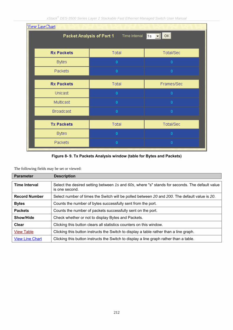
xStack® DES-3500 Series Layer 2 Stackable Fast Ethernet Managed Switch User Manual
212
Figure 8- 9. Tx Packets Analysis window (table for Bytes and Packets)
The following fields may be set or viewed:
Parameter Description
Time Interval Select the desired setting between 1s and 60s, where "s" stands for seconds. The default value is one second.
Record Number Select number of times the Switch will be polled between 20 and 200. The default value is 20.
Bytes Counts the number of bytes successfully sent from the port.
Packets Counts the number of packets successfully sent on the port.
Show/Hide Check whether or not to display Bytes and Packets.
Clear Clicking this button clears all statistics counters on this window.
View Table Clicking this button instructs the Switch to display a table rather than a line graph.
View Line Chart Clicking this button instructs the Switch to display a line graph rather than a table.

xStack® DES-3500 Series Layer 2 Stackable Fast Ethernet Managed Switch User Manual
213
Errors The Web Manager allows port error statistics compiled by the Switch's management agent to be viewed as either a line graph or a table. Four windows are offered.
Received (RX) Click, Monitoring > Error > Received (RX) to view the following graph of error packets received on the Switch.
Figure 8- 10. Rx Error Analysis window (line graph)
To view the Received Error Packets Table, click the link View Table, which will show the following table:

xStack® DES-3500 Series Layer 2 Stackable Fast Ethernet Managed Switch User Manual
214
Figure 8- 11. Rx Error Analysis window (table)
The following fields can be set:
Parameter Description
Time Interval Select the desired setting between 1s and 60s, where "s" stands for seconds. The default value is one second.
Record Number Select number of times the Switch will be polled between 20 and 200. The default value is 20.
Crc Error Counts otherwise valid packets that did not end on a byte (octet) boundary.
Under Size The number of packets detected that are less than the minimum permitted packets size of 64 bytes and have a good CRC. Undersize packets usually indicate collision fragments, a nor-mal network occurrence.
Over Size Counts packets received that were longer than 1518 octets, or if a VLAN frame is 1522 octets, and less than the MAX_PKT_LEN. Internally, MAX_PKT_LEN is equal to 1522.
Fragment The number of packets less than 64 bytes with either bad framing or an invalid CRC. These are normally the result of collisions.
Jabber The number of packets with lengths more than the MAX_PKT_LEN bytes. Internally, MAX_PKT_LEN is equal to 1522.
Drop The number of packets that are dropped by this port since the last Switch reboot.
Show/Hide Check whether or not to display Crc Error, Under Size, Over Size, Fragment, Jabber, and Drop errors.
Clear Clicking this button clears all statistics counters on this window.
View Table Clicking this button instructs the Switch to display a table rather than a line graph.
View Line Chart Clicking this button instructs the Switch to display a line graph rather than a table.

xStack® DES-3500 Series Layer 2 Stackable Fast Ethernet Managed Switch User Manual
215
Transmitted (TX) Click, Monitoring > Error > Transmitted (TX) to view the following graph of error packets received on the Switch.
Figure 8- 12. Tx Error Analysis window (line graph)
To view the Transmitted Error Packets Table, click the link View Table, which will show the following table:
Figure 8- 13. Tx Error Analysis window (table)

xStack® DES-3500 Series Layer 2 Stackable Fast Ethernet Managed Switch User Manual
216
The following fields may be set or viewed:
Parameter Description
Time Interval Select the desired setting between 1s and 60s, where "s" stands for seconds. The default value is one second.
Record Number Select number of times the Switch will be polled between 20 and 200. The default value is 20.
ExDefer Counts the number of packets for which the first transmission attempt on a particular interface was delayed because the medium was busy.
LateColl Counts the number of times that a collision is detected later than 512 bit-times into the transmission of a packet.
ExColl Excessive Collisions. The number of packets for which transmission failed due to excessive collisions.
SingColl Single Collision Frames. The number of successfully transmitted packets for which transmission is inhibited by more than one collision.
Coll An estimate of the total number of collisions on this network segment.
Show/Hide Check whether or not to display ExDefer, LateColl, ExColl, SingColl, and Coll errors.
Clear Clicking this button clears all statistics counters on this window.
View Table Clicking this button instructs the Switch to display a table rather than a line graph.
View Line Chart Clicking this button instructs the Switch to display a line graph rather than a table.
Size - Packet Size The Web Manager allows packets received by the Switch, arranged in six groups and classed by size, to be viewed as either a line graph or a table. Two windows are offered. To view this window click, Monitoring > Errors > Packet Size.

xStack® DES-3500 Series Layer 2 Stackable Fast Ethernet Managed Switch User Manual
217
Figure 8- 14. Rx Size Analysis window (line graph)
To view the Packet Size Analysis Table, click the link View Table, which will show the following table:
Figure 8- 15. Rx Size Analysis window (table)

xStack® DES-3500 Series Layer 2 Stackable Fast Ethernet Managed Switch User Manual
218
The following fields can be set or viewed:
Parameter Description
Time Interval Select the desired setting between 1s and 60s, where "s" stands for seconds. The default value is one second.
Record Number Select number of times the Switch will be polled between 20 and 200. The default value is 20.
64 The total number of packets (including bad packets) received that were 64 octets in length (excluding framing bits but including FCS octets).
65-127 The total number of packets (including bad packets) received that were between 65 and 127 octets in length inclusive (excluding framing bits but including FCS octets).
128-255 The total number of packets (including bad packets) received that were between 128 and 255 octets in length inclusive (excluding framing bits but including FCS octets).
256-511 The total number of packets (including bad packets) received that were between 256 and 511 octets in length inclusive (excluding framing bits but including FCS octets).
512-1023 The total number of packets (including bad packets) received that were between 512 and 1023 octets in length inclusive (excluding framing bits but including FCS octets).
1024-1518 The total number of packets (including bad packets) received that were between 1024 and 1518 octets in length inclusive (excluding framing bits but including FCS octets).
Show/Hide Check whether or not to display 64, 65-127, 128-255, 256-511, 512-1023, and 1024-1518 packets received.
Clear Clicking this button clears all statistics counters on this window.
View Table Clicking this button instructs the Switch to display a table rather than a line graph.
View Line Chart Clicking this button instructs the Switch to display a line graph rather than a table.

xStack® DES-3500 Series Layer 2 Stackable Fast Ethernet Managed Switch User Manual
219
MAC Address
Figure 8- 16. MAC Address Table window
The following fields can be viewed or set:
Parameter Description
VLAN ID Enter a VLAN ID for the forwarding table to be browsed by.
MAC Address Enter a MAC address for the forwarding table to be browsed by.
Find Allows the user to move to a sector of the database corresponding to a user defined port, VLAN, or MAC address.
VID The VLAN ID of the VLAN the port is a member of.
MAC Address The MAC address entered into the address table.
Port The port that the MAC address above corresponds to.
Learned How the Switch discovered the MAC address. The possible entries are Dynamic, Self, and Static.
Next Click this button to view the next page of the address table.
View All Entry Clicking this button will allow the user to view all entries of the address table.
Delete All Entry Clicking this button will allow the user to delete all entries of the address table.
This allows the Switch's dynamic MAC address forwarding table to be viewed. When the Switch learns an association between a MAC address and a port number, it makes an entry into its forwarding table. These entries are then used to forward packets through the Switch. To view the MAC Address forwarding table, click, Monitoring > MAC Address:

xStack® DES-3500 Series Layer 2 Stackable Fast Ethernet Managed Switch User Manual
220
Switch History Log The Web manager allows the Switch's history log, as compiled by the Switch's management agent, to be viewed. To view the Switch history log click, Maintenance > Switch History Log.
Figure 8- 17. Switch History window
The Switch can record event information in its own logs, to designated SNMP trap receiving stations, and to the PC connected to the console manager. Click Next to go to the next page of the Switch History Log. Clicking Clear will allow the user to clear the Switch History Log. The information is described as follows:
Parameter Description
Sequence A counter incremented whenever an entry to the Switch's history log is made. The table displays the last entry (highest sequence number) first.
Time Displays the time in days, hours, and minutes since the Switch was last restarted.
Log Text Displays text describing the event that triggered the history log entry.
NOTE: For detailed information regarding Log entries that will appear in this window, please refer to Appendix C at the back of this manual.

xStack® DES-3500 Series Layer 2 Stackable Fast Ethernet Managed Switch User Manual
221
IGMP Snooping Group IGMP Snooping allows the Switch to read the Multicast Group IP address and the corresponding MAC address from IGMP packets that pass through the Switch. The number of IGMP reports that were snooped is displayed in the Reports field. To view the IGMP Snooping Table, click Monitoring > IGMP Snooping Group.
Figure 8- 18. IGMP Snooping Table window
The user may search the IGMP Snooping Table by VLAN ID (VID) by entering the VID in the top left hand corner and clicking Search.
NOTE: The Switch supports up to 128 IGMP Snooping groups.
The following field can be viewed:
Parameter Description
VLAN ID The VLAN ID (VID) of the multicast group.
Multicast Group The IP address of the multicast group.
MAC Address The MAC address of the multicast group.
Queries A read-only field showing the status of the Querier State. Disabled implies that the Switch is not transmitting IGMP Snooping Query packets, while Enabled means those packets are being transmitted.
Reports The total number of reports received for this group.
Port Map These are the ports where the IGMP packets were snooped are displayed.
NOTE: To configure IGMP snooping for the DES-3500 Series switches, go to the Configuration folder and select IGMP. Configuration and other information concerning IGMP snooping may be found in Section 6 of this manual under IGMP.

xStack® DES-3500 Series Layer 2 Stackable Fast Ethernet Managed Switch User Manual
222
IGMP Snooping Forwarding This window will display the current IGMP snooping forwarding table entries currently configured on the Switch. To view the following screen, click, Monitoring > IGMP Snooping Forwarding.
Figure 8- 19. IGMP Snooping Forwarding Table window
The user may search the IGMP Snooping Forwarding Table by VID clicking the top left hand corner Search button. The following field can be viewed:
Parameter Description
VLAN ID The VLAN ID (VID) of the multicast group.
Multicast Group The IP address of the multicast group.
MAC Address The MAC address of the multicast group.
Port Map These are the ports where the IGMP packets were snooped are displayed.

xStack® DES-3500 Series Layer 2 Stackable Fast Ethernet Managed Switch User Manual
223
VLAN Status This allows the VLAN status for each of the Switch's ports to be viewed by VLAN. This window displays the ports on the Switch that are currently Egress or Tag ports. To view the following table, click Monitoring > VLAN Status.
Figure 8- 20. VLAN Status window
Router Port This displays which of the Switch's ports are currently configured as router ports. A router port configured by a user (using the console or Web-based management interfaces) is displayed as a static router port, designated by S. D designates a router port that is dynamically configured by the Switch. To view the following window, click Monitoring > Router Port.
Figure 8- 21. Router Port window
Port Access Control The following windows are used to monitor 802.1x statistics of the Switch, on a per port basis.

xStack® DES-3500 Series Layer 2 Stackable Fast Ethernet Managed Switch User Manual
224
Authenticator State The following section window displays the 802.1X Status on the Switch. To view the Authenticator State, click Monitoring > Port Access Control > Authenticator State.
Figure 8- 22. Authenticator State window – Port-based 802.1x

xStack® DES-3500 Series Layer 2 Stackable Fast Ethernet Managed Switch User Manual
225
Figure 8- 23. Show Authenticator State window – MAC-Based 802.1x
This window displays the Authenticator State for individual ports on a selected device. To select a unit within the switch stack, use the pull-down menu at the top of the window and click Apply. A polling interval between 1 and 60 seconds can be set using the drop-down menu at the top of the window and clicking OK. The information on this window is described as follows:
Parameter Description
Auth PAE State The Authenticator PAE State value can be: Initialize, Disconnected, Connecting, Authenticating, Authenticated, Aborting, Held, Force_Auth, Force_Unauth, or N/A. N/A (Not Available) indicates that the port's authenticator capability is disabled.
Backend State The Backend Authentication State can be Request, Response, Success, Fail, Timeout, Idle, Initialize, or N/A. N/A (Not Available) indicates that the port's authenticator capability is disabled.
Port Status Controlled Port Status can be Authorized, Unauthorized, or N/A.

xStack® DES-3500 Series Layer 2 Stackable Fast Ethernet Managed Switch User Manual
226
Layer 3 Features Browse ARP Table The ARP Table window may be found by clicking, Monitoring > Layer 3 Feature > Browse ARP Table. This window will show current ARP entries on the Switch. To search a specific ARP entry, enter an interface name into the Interface Name field or an IP address and click Find.
Figure 8- 24. ARP Table window

xStack® DES-3500 Series Layer 2 Stackable Fast Ethernet Managed Switch User Manual
227
Safeguard Engine Status The following window displays parameters configured for and about the Safeguard Engine Status currently set on the Switch. To view this window click, Monitoring > Safeguard Engine Status.
Figure 8- 25. Safeguard Engine Status and CPU Utilization Information window
The information is described as follows:
Parameter Description
State Displays the current running state of the Safeguard Engine, whether enabled or disabled.
Current Status Displays the current running status of the Safeguard Engine, whether in exhausted mode or normal mode.
Interval Displays the time interval between the checking of the rising and falling threshold of packets entering the Switch. The default setting is 5 seconds.
Rising Threshold Displays the set percentage of the rising threshold of packets determinant of the Safeguard Engine.
Falling Threshold Displays the set percentage of the falling threshold of packets determinant of the Safeguard Engine.
Trap/log Displays the status of the sending of messages to the switch’s log or SNMP trap. Enabled will denote the switch will send trap messages in the event of a Safeguard Engine engagement.

xStack® DES-3500 Series Layer 2 Stackable Fast Ethernet Managed Switch User Manual
228
Cable Diagnostic The following window displays parameters configured for and about the Cable Diagnostics currently set on the Switch. To view this window click, Monitoring > Cable Diagnostic.
Figure 8- 26. Cable Diagnostic Table window

xStack® DES-3500 Series Layer 2 Stackable Fast Ethernet Managed Switch User Manual
229
Section 9 Maintenance
TFTP Services
Multiple Image Services
Ping Test
Save Changes
Reset
Reset System
Reset Config
Reboot Device
Logout
TFTP Services Trivial File Transfer Protocol (TFTP) services allow the Switch's firmware to be upgraded by transferring a new firmware file from a TFTP server to the Switch. A configuration file can also be loaded into the Switch from a TFTP server. Switch settings can be saved to the TFTP server, and a history log can be uploaded from the Switch to the TFTP server.
Download Firmware To update the Switch's firmware, click Maintenance > TFTP Services > Download Firmware:
Figure 9- 1. Download/Update Firmware from TFTP Server window
The Switch can hold two firmware versions for the user, which can be specified in the Type field by clicking the Update radio button and selecting the Image 1 or Image 2. To download or update firmware, configure the following fields and click Start.
Parameter Description
Server IP Enter the IP address of the server from which you wish to download firmware.
File Name Specify the path and filename of the firmware on the Server.

xStack® DES-3500 Series Layer 2 Stackable Fast Ethernet Managed Switch User Manual
230
Type Specify the purpose of the firmware: Download: Clicking this radio button will specify a download to the Switch. This will be the firmware that the Switch will immediately use. Update: Clicking this radio button will save the firmware to the Switch's memory but not configure the Switch for this firmware. The Switch may hold two firmware versions specified as Section 1 and Section 2.
Information about firmware on the Switch can be viewed in the Firmware Management table in the same window. It holds the following information:
Parameter Description
ID The user-defined Section ID of the firmware on the Switch.
Boot Status The firmware that is currently being run on the Switch will be identified in this field with the term "Boot".
Version The runtime version of the firmware.
Size The size of the firmware, in bytes.
Date The date that the firmware was added to the Switch.
From The IP address of the Server from which the firmware came.
User The name of the user who downloaded the firmware.
Set Boot Click the Apply button in this field to set the firmware version to be used upon the next boot up of the Switch.
Delete Click the X in this column to permanently delete the corresponding firmware from the Switch.
Download Configuration File To download a settings file from a TFTP server, click Maintenance > TFTP Service > Download Configuration File:
Figure 9- 2. Download Settings from TFTP Server window
Enter the IP address of the TFTP server and specify the location of the switch settings file on the TFTP server. Click Start to record the IP address of the TFTP server and to initiate the file transfer.
Upload Configuration To upload the switch settings to a TFTP server, click Maintenance > TFTP Services > Upload Configuration:
Figure 9- 3. Upload Settings to TFTP Server window
Enter the IP address of the TFTP server and the path and filename for the switch settings on the TFTP server. Click Start to record the IP address of the TFTP server and to initiate the file transfer.

xStack® DES-3500 Series Layer 2 Stackable Fast Ethernet Managed Switch User Manual
231
Upload Log To upload the switch history log file to a TFTP server, click Maintenance > TFTP Services > Upload Log:
Figure 9- 4. Upload Log to TFTP Server window
Enter the IP address of the TFTP server and the path and filename for the history log on the TFTP server. Click Start to record the IP address of the TFTP server and to initiate the file transfer.
Multiple Image Services The Multiple Image Services folder allows users of the xStack® family of switches to configure and view information regarding firmware located on the Switch. The Switch allows two firmware images to be stored in its memory and either can be configured to be the boot up firmware for the Switch. For information regarding firmware images located on the Switch, open the Firmware Information link. The default setting for the Switch’s firmware will have the boot up firmware stored in Image 1, but the user may set either firmware stored to be the boot up firmware by using the Config Firmware Image window.
Firmware Information The following screen allows the user to view information about current firmware images stored on the Switch. To access the following screen, click Maintenance > Multiple Image Services > Firmware Information.
Figure 9- 5. Firmware Information window
This window holds the following information:
Parameter Description
BOX States the stacking ID number of the switch in the switch stack.
ID States the image ID number of the firmware in the Switch’s memory. The Switch can store 2 firmware images for use. Image ID 1 will be the default boot up firmware for the Switch unless otherwise configured by the user.

xStack® DES-3500 Series Layer 2 Stackable Fast Ethernet Managed Switch User Manual
232
Version States the firmware version.
Size States the size of the corresponding firmware, in bytes.
Update Time States the specific time the firmware version was downloaded to the Switch.
From States the IP address of the origin of the firmware. There are five ways firmware may be downloaded to the Switch.
• R – If the IP address has this letter attached to it, it denotes a firmware upgrade through the Console Serial Port (RS-232).
• T - If the IP address has this letter attached to it, it denotes a firmware upgrade through Telnet.
• S - If the IP address has this letter attached to it, it denotes a firmware upgrade through the Simple Network Management Protocol (SNMP).
• W - If the IP address has this letter attached to it, it denotes a firmware upgrade through the web-based management interface.
• SIM – If the IP address has this letter attached to it, it denotes a firmware upgrade through the Single IP Management feature.
User States the user who downloaded the firmware. This field may read “Anonymous” or “Unknown” for users that are not identified.
Config Firmware Image The Config Firmware Image window allows users to configure firmware images saved in the memory of the Switch. To access the following window, click Maintenance > Multiple Image Services > Config Firmware Image.
Figure 9- 6. Config Firmware Image window
This window offers the following information:
Parameter Description
Image Select the firmware image to be configured using the pull-down menu. The Switch allows two firmware images to be stored in the Switch’s memory.
Action This field has two options for configuration.
• Delete – Select this option to delete the firmware image specified in the Image field above.
• Boot – Select this option to set the firmware image specified above as the boot up firmware for the Switch. This firmware will be set as the boot up firmware after a switch reboot has been performed. The default setting has firmware image ID 1 as the boot up firmware image for the Switch unless specified here.
Click Apply to implement changes made.
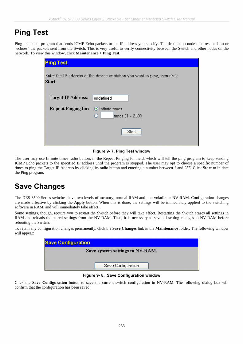
xStack® DES-3500 Series Layer 2 Stackable Fast Ethernet Managed Switch User Manual
233
Ping Test Ping is a small program that sends ICMP Echo packets to the IP address you specify. The destination node then responds to or "echoes" the packets sent from the Switch. This is very useful to verify connectivity between the Switch and other nodes on the network. To view this window, click Maintenance > Ping Test.
Figure 9- 7. Ping Test window
The user may use Infinite times radio button, in the Repeat Pinging for field, which will tell the ping program to keep sending ICMP Echo packets to the specified IP address until the program is stopped. The user may opt to choose a specific number of times to ping the Target IP Address by clicking its radio button and entering a number between 1 and 255. Click Start to initiate the Ping program.
Save Changes The DES-3500 Series switches have two levels of memory; normal RAM and non-volatile or NV-RAM. Configuration changes are made effective by clicking the Apply button. When this is done, the settings will be immediately applied to the switching software in RAM, and will immediately take effect. Some settings, though, require you to restart the Switch before they will take effect. Restarting the Switch erases all settings in RAM and reloads the stored settings from the NV-RAM. Thus, it is necessary to save all setting changes to NV-RAM before rebooting the Switch. To retain any configuration changes permanently, click the Save Changes link in the Maintenance folder. The following window will appear:
Figure 9- 8. Save Configuration window
Click the Save Configuration button to save the current switch configuration in NV-RAM. The following dialog box will confirm that the configuration has been saved:
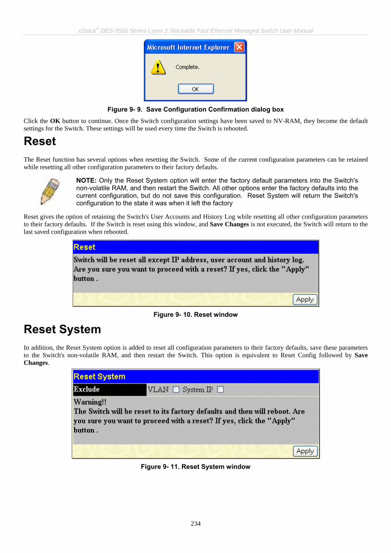
xStack® DES-3500 Series Layer 2 Stackable Fast Ethernet Managed Switch User Manual
234
Figure 9- 9. Save Configuration Confirmation dialog box
Click the OK button to continue. Once the Switch configuration settings have been saved to NV-RAM, they become the default settings for the Switch. These settings will be used every time the Switch is rebooted.
Reset The Reset function has several options when resetting the Switch. Some of the current configuration parameters can be retained while resetting all other configuration parameters to their factory defaults.
NOTE: Only the Reset System option will enter the factory default parameters into the Switch's non-volatile RAM, and then restart the Switch. All other options enter the factory defaults into the current configuration, but do not save this configuration. Reset System will return the Switch's configuration to the state it was when it left the factory
Reset gives the option of retaining the Switch's User Accounts and History Log while resetting all other configuration parameters to their factory defaults. If the Switch is reset using this window, and Save Changes is not executed, the Switch will return to the last saved configuration when rebooted.
Figure 9- 10. Reset window
Reset System In addition, the Reset System option is added to reset all configuration parameters to their factory defaults, save these parameters to the Switch's non-volatile RAM, and then restart the Switch. This option is equivalent to Reset Config followed by Save Changes.
Figure 9- 11. Reset System window
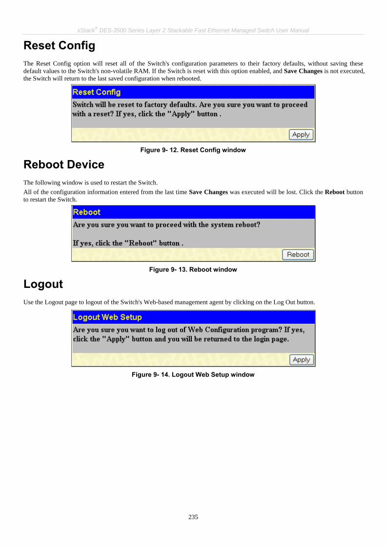
xStack® DES-3500 Series Layer 2 Stackable Fast Ethernet Managed Switch User Manual
235
Reset Config The Reset Config option will reset all of the Switch's configuration parameters to their factory defaults, without saving these default values to the Switch's non-volatile RAM. If the Switch is reset with this option enabled, and Save Changes is not executed, the Switch will return to the last saved configuration when rebooted.
Figure 9- 12. Reset Config window
Reboot Device The following window is used to restart the Switch. All of the configuration information entered from the last time Save Changes was executed will be lost. Click the Reboot button to restart the Switch.
Figure 9- 13. Reboot window
Logout Use the Logout page to logout of the Switch's Web-based management agent by clicking on the Log Out button.
Figure 9- 14. Logout Web Setup window

xStack® DES-3500 Series Layer 2 Stackable Fast Ethernet Managed Switch User Manual
236
Section 10 D-Link Single IP Management
Single IP Management (SIM) Overview
Topology
Firmware Upgrade
Configuration Backup/Restore
Upload Log File
Single IP Management (SIM) Overview Simply put, D-Link Single IP Management is a concept that will stack switches together over Ethernet instead of using stacking ports or modules. There are some advantages in implementing the "Single IP Management" feature:
1. SIM can simplify management of small workgroups or wiring closets while scaling the network to handle increased bandwidth demand.
2. SIM can reduce the number of IP address needed in your network. 3. SIM can eliminate any specialized cables for stacking connectivity and remove the distance barriers that typically limit
your topology options when using other stacking technology. Switches using D-Link Single IP Management (labeled here as SIM) must conform to the following rules:
• SIM is an optional feature on the Switch and can easily be enabled or disabled through the Command Line Interface or Web Interface. SIM grouping has no effect on the normal operation of the Switch in the user's network.
• There are three classifications for switches using SIM. The Commander Switch (CS), which is the master switch of the group, Member Switch (MS), which is a switch that is recognized by the CS a member of a SIM group, and a Candidate Switch (CaS), which is a Switch that has a physical link to the SIM group but has not been recognized by the CS as a member of the SIM group.
• A SIM group can only have one Commander Switch (CS). • All switches in a particular SIM group must be in the same IP subnet (broadcast domain). Members of a SIM group
cannot cross a router. • A SIM group accepts one Commander Switch (numbered 0) and up to 32 switches (numbered 0-31).
There is no limit to the number of SIM groups in the same IP subnet (broadcast domain), however a single switch can only belong to one group. If multiple VLANs are configured, the SIM group will only utilize the system VLAN that has been assigned the switch’s IP address. SIM allows intermediate devices that do not support SIM. This enables the user to manage switches that are more than one hop away from the CS. The SIM group is a group of switches that are managed as a single entity. The DES-3500 Series switches may take on three different roles:
1. Commander Switch (CS) - This is a switch that has been manually configured as the controlling device for a group, and takes on the following characteristics:
• It has an IP Address. • It is not a command switch or member switch of another Single IP group. • It is connected to the member switches through its management VLAN.
2. Member Switch (MS) - This is a switch that has joined a single IP group and is accessible from the CS, and it takes on the following characteristics:
• It is not a CS or MS of another IP group. • It is connected to the CS through the CS management VLAN.
3. Candidate Switch(CaS) - This is a switch that is ready to join a SIM group but is not yet a member of the SIM group. The Candidate Switch may join the SIM group through an automatic function of the DES-3500 Series switches, or by

xStack® DES-3500 Series Layer 2 Stackable Fast Ethernet Managed Switch User Manual
237
manually configuring it to be a MS of a SIM group. A switch configured as a CaS is not a member of a SIM group and will take on the following characteristics:
• It is not a CS or MS of another Single IP group.
• It is connected to the CS through the CS management VLAN
The following rules also apply to the above roles:
• Each device begins in a Commander state.
• CS's must change their role to CaS and then to MS, to become a MS of a SIM group. Thus the CS cannot directly be converted to a MS.
• The user can manually configure a CS to become a CaS.
A MS can become a CaS by:
• Being configured as a CaS through the CS.
• If report packets from the CS to the MS time out.
• The user can manually configure a CaS to become a CS
• The CaS can be configured through the CS to become a MS.
After configuring one switch to operate as the CS of a SIM group, additional DES-3500 Series switches may join the group either by an automatic method or by manually configuring the Switch to be a MS. The CS will then serve as the in band entry point for access to the MS. The CS's IP address will become the path to all MS's of the group and the CS's Administrator's password, and/or authentication will control access to all MS's of the SIM group. With SIM enabled, the applications in the CS will redirect the packet instead of executing the packets. The applications will decode the packet from the administrator, modify some data, and then send it to the MS. After execution, the CS may receive a response packet from the MS, which it will encode and send it back to the administrator. When a CS becomes a MS, it automatically becomes a member of the first SNMP community (include read/write and read only) to which the CS belongs. However, if a MS has its own IP address, it can belong to SNMP communities to which other switches in the group, including the CS, do not belong.
The Upgrade to v1.6 To better improve SIM management, the xStack® DES-3500 Series switches have been upgraded to version 1.6 in this release. Many improvements have been made, including: 1. The Commander Switch (CS) now has the capability to automatically rediscover member switches that have left the SIM group, either through a reboot or web malfunction. This feature is accomplished through the use of Discover packets and Maintain packets that previously set SIM members will emit after a reboot. Once a MS has had its MAC address and password saved to the CS’s database, if a reboot occurs in the MS, the CS will keep this MS information in its database and when a MS has been rediscovered, it will add the MS back into the SIM tree automatically. No configuration will be necessary to rediscover these switches. There are some instances where pre-saved MS switches cannot be rediscovered. For example, if the Switch is still powered down, if it has become the member of another group, or if it has been configured to be a Commander Switch, the rediscovery process cannot occur.
3. This version will support multiple switch upload and downloads for firmware, configuration files and log files, as follows:
Firmware – The switch now supports multiple MS firmware downloads from a TFTP server. Configuration Files – This switch now supports multiple downloading and uploading of configuration files both to (for configuration restoration) and from (for configuration backup) MS’s, using a TFTP server. Log – The switch now supports uploading multiple MS log files to a TFTP server.
2. The topology map now includes new features for connections that are a member of a port trunking group. It will display the speed and number of Ethernet connections creating this port trunk group, as shown in the adjacent picture.
NOTE: For more details regarding improvements made in SIMv1.6, please refer to the D-Link Single IP Management White Paper located on the D-Link website.

xStack® DES-3500 Series Layer 2 Stackable Fast Ethernet Managed Switch User Manual
238
4. The user may zoom in and zoom out when utilizing the topology window to get a better, more defined view of the configurations.
SIM Using the Web Interface All DES-3500 Series switches are set as Candidate (CaS) switches, as their factory default configuration and Single IP Management will be disabled. To enable SIM for the Switch using the Web interface, click Single IP Management > SIM Settings.
Figure 10- 1. SIM Settings window (disabled)
Change the SIM State to Enabled using the pull-down menu and click Apply. The window will then refresh and the SIM Settings window will look like this:
Figure 10- 2. SIM Settings window (enabled)
The following parameters can be set:
Parameters Description
SIM State Use the pull-down menu to either enable or disable the SIM state on the Switch. Disabled will render all SIM functions on the Switch inoperable.
Role State Use the pull-down menu to change the SIM role of the Switch. The two choices are: Candidate - A Candidate Switch (CaS) is not the member of a SIM group but is connected to a Commander Switch. This is the default setting for the SIM role of the DES-3500 Series switches. Commander - Choosing this parameter will make the Switch a Commander Switch (CS). The user may join other switches to this Switch, over Ethernet, to be part of its SIM group. Choosing this option will also enable the Switch to be configured for SIM.
Discovery Interval The user may set the discovery protocol interval, in seconds that the Switch will send out discovery packets. Returning information to a Commander Switch will include information about other switches connected to it. (Ex. MS, CaS). The user may set the Discovery Interval from 30 to 90 seconds.
Holdtime This parameter may be set for the time, in seconds; the Switch will hold information sent to it from other switches, utilizing the Discovery Interval. The user may set the hold time from 100 to 255 seconds.
Group Name The user may enter a Group Name of up to 64 characters to define the SIM group created.

xStack® DES-3500 Series Layer 2 Stackable Fast Ethernet Managed Switch User Manual
239
Click Apply to implement the settings changed. After enabling the Switch to be a Commander Switch (CS), the Single IP Management folder will then contain four added links to aid the user in configuring SIM through the web, including Topology, Firmware Upgrade, Configuration Backup/Restore and Upload Log File.
Topology The Topology window will be used to configure and manage the Switch within the SIM group and requires Java script to function properly on your computer. The following message should appear the first time the user clicks the Topology link in the Single IP Management folder.
Figure 10- 3. Java window
Clicking the here link will setup the Java Runtime Environment on your server and lead you to the topology window, as seen below.
Figure 10- 4. Single IP Management window-Tree View
The Tree View window holds the following information under the Data tab:
Parameter Description
Device Name This field will display the Device Name of the switches in the SIM group configured by the user. If no Device Name is configured by the name, it will be given the name default and tagged with the last six digits of the MAC Address to identify it.
Local Port Displays the number of the physical port on the CS that the MS or CaS is connected to. The CS will have no entry in this field. The CS will not display an entry in this field.

xStack® DES-3500 Series Layer 2 Stackable Fast Ethernet Managed Switch User Manual
240
Speed Displays the connection speed between the CS and the MS or CaS. The CS will not display an entry in this field.
Remote Port Displays the number of the physical port on the MS or CaS that the CS is connected to. The CS will have no entry in this field. The CS will not display an entry in this field.
MAC Address Displays the MAC Address of the corresponding Switch.
Model Name Displays the full Model Name of the corresponding Switch.
To view the Topology Map, click the View menu in the toolbar and then Topology, which will produce the following window. The Topology View will refresh itself periodically (20 seconds by default).
Figure 10- 5. Topology view
This window will display how the devices within the Single IP Management Group are connected to other groups and devices. Possible icons in this window are as follows:
Icon Description
Group
Layer 2 commander switch
Layer 3 commander switch
Commander switch of other group

xStack® DES-3500 Series Layer 2 Stackable Fast Ethernet Managed Switch User Manual
241
Layer 2-member switch.
Layer 3 member switch
Member switch of other group
Layer 2 candidate switch
Layer 3 candidate switch
Unknown device
Non-SIM devices
Tool Tips In the Topology view window, the mouse plays an important role in configuration and in viewing device information. Setting the mouse cursor over a specific device in the topology window (tool tip) will display the same information about a specific device as the Tree view does. See the window below for an example.
Figure 10- 6. Device Information Utilizing the Tool Tip
Setting the mouse cursor over a line between two devices will display the connection speed between the two devices, as shown below.

xStack® DES-3500 Series Layer 2 Stackable Fast Ethernet Managed Switch User Manual
242
Figure 10- 7. Port Speed Utilizing the Tool Tip
Right-Click Right clicking on a device will allow the user to perform various functions, depending on the role of the Switch in the SIM group and the icon associated with it.
Group Icon
Figure 10- 8. Right-Clicking a Group Icon
The following options may appear for the user to configure:
• Collapse - to collapse the group that will be represented by a single icon.
• Expand - to expand the SIM group, in detail.
• Property - to pop up a window to display the group information.

xStack® DES-3500 Series Layer 2 Stackable Fast Ethernet Managed Switch User Manual
243
Figure 10- 9. Property window
Commander Switch Icon
Figure 10- 10. Right-Clicking a Commander Icon
The following options may appear for the user to configure:
• Collapse - to collapse the group that will be represented by a single icon.
• Expand - to expand the SIM group, in detail.
• Property - to pop up a window to display the group information.

xStack® DES-3500 Series Layer 2 Stackable Fast Ethernet Managed Switch User Manual
244
Figure 10- 11. Property window
Member Switch Icon
Figure 10- 12. Right-Clicking a Member icon
The following options may appear for the user to configure:
• Collapse - to collapse the group that will be represented by a single icon.
• Expand - to expand the SIM group, in detail.
• Remove from group - remove a member from a group.
• Configure - launch the web management to configure the Switch.
• Property - to pop up a window to display the device information.

xStack® DES-3500 Series Layer 2 Stackable Fast Ethernet Managed Switch User Manual
245
Figure 10- 13. Property window
Candidate Switch Icon
Figure 10- 14. Right-Clicking a Candidate icon
The following options may appear for the user to configure:
• Collapse - to collapse the group that will be represented by a single icon.
• Expand - to expand the SIM group, in detail.
• Add to group - add a candidate to a group. Clicking this option will reveal the following dialog box for the user to enter a password for authentication from the Candidate Switch before being added to the SIM group. Click OK to enter the password or Cancel to exit the window.
Figure 10- 15. Input password dialog box
• Property - to pop up a window to display the device information, as shown below.

xStack® DES-3500 Series Layer 2 Stackable Fast Ethernet Managed Switch User Manual
246
Figure 10- 16. Property window
This window holds the following information:
Parameter Description
Device Name This field will display the Device Name of the switches in the SIM group configured by the user. If no Device Name is configured by the name, it will be given the name default and tagged with the last six digits of the MAC Address to identify it.
Module Name Displays the full module name of the switch that was right-clicked.
MAC Address Displays the MAC Address of the corresponding Switch.
Remote Port No. Displays the number of the physical port on the MS or CaS that the CS is connected to. The CS will have no entry in this field.
Local Port No. Displays the number of the physical port on the CS that the MS or CaS is connected to. The CS will have no entry in this field.
Port Speed Displays the connection speed between the CS and the MS or CaS. The CS will have no entry in this field.
Click Close to close the Property window.

xStack® DES-3500 Series Layer 2 Stackable Fast Ethernet Managed Switch User Manual
247
Menu Bar The Single IP Management window contains a menu bar for device configurations, as seen below.
Figure 10- 17. Menu Bar of the Topology View
The five menus on the menu bar are as follows.
File • Print Setup - will view the image to be printed.
• Print Topology - will print the topology map.
• Preference - will set display properties, such as polling interval, and the views to open at SIM startup.
Group • Add to group - add a candidate to a group. Clicking this option will reveal the following dialog box for the user to
enter a password for authentication from the Candidate Switch before being added to the SIM group. Click OK to enter the password or Cancel to exit the window.
Figure 10- 18. Input password dialog box
• Remove from Group - remove an MS from the group.
Device • Configure - will open the web manager for the specific device.
View • Refresh - update the views with the latest status.
• Topology - display the Topology view.
Help • About - Will display the SIM information, including the current SIM version.

xStack® DES-3500 Series Layer 2 Stackable Fast Ethernet Managed Switch User Manual
248
NOTE: Upon this firmware release, some functions of the SIM can only be configured through the Command Line Interface. See the DES-3500 Series Command Line Interface Reference Manual for more information on SIM and its configurations.
Firmware Upgrade This window is used to upgrade firmware from the Commander Switch to the Member Switch. Member Switches will be listed in the table and will be specified by Port (port on the CS where the MS resides), MAC Address, Model Name and Version. To specify a certain Switch for firmware download, click its corresponding check box under the Port heading. To update the firmware, enter the Server IP Address where the firmware resides and enter the Path/Filename of the firmware. Click Download to initiate the file transfer.
Figure 10- 19. Firmware Upgrade window
Configuration File Backup/Restore This window is used to upgrade configuration files from the Commander Switch to the Member Switch. Member Switches will be listed in the table and will be specified by Port (port on the CS where the MS resides), MAC Address, Model Name and Version. To specify a certain Switch for upgrading configuration files, click its corresponding radio button under the Port heading. To update the configuration file, enter the Server IP Address where the firmware resides and enter the Path/Filename of the firmware. Click Download to initiate the file transfer.
Figure 10- 20. Configuration File Backup/Restore window
Upload Log File The following window is used to upload log files from SIM member switches to a specified PC. To view this window, click Single IP Management > Upload Log File. To upload a log file, enter the IP address of the SIM member switch and then enter the path on your PC to which to save this file. Click Upload to initiate the file transfer.

xStack® DES-3500 Series Layer 2 Stackable Fast Ethernet Managed Switch User Manual
249
Figure 10- 21. Upload Log File window

xStack® DES-3500 Series Layer 2 Stackable Fast Ethernet Managed Switch User Manual
250
Appendix A Technical Specifications
General
Standards IEEE 802.3 Nway auto-negotiation IEEE 802.3 10BASE-T Ethernet IEEE 802.3u 100BASE-TX Fast Ethernet IEEE 802.3ab 1000BASE-T Gigabit Ethernet IEEE 802.3z 1000BASE-T (SFP “Mini GBIC”) IEEE 802.1D Spanning Tree IEEE 802.1w Rapid Spanning Tree IEEE 802.1s Multiple Spanning Tree IEEE 802.1Q VLAN IEEE 802.1p Priority Queues IEEE 802.3ad Link Aggregation Control IEEE 802.3x Full-duplex Flow Control
Protocols CSMA/CD
Data Transfer Rates: Ethernet Fast Ethernet Gigabit Ethernet Fiber Optic
Half-duplex Full-duplex 10 Mbps 20Mbps 100Mbps 200Mbps n/a 2000Mbps SFP (Mini GBIC) Support IEEE 802.3z 1000BASE-LX (DEM-310GT transceiver) IEEE 802.3z 1000BASE-SX (DEM-311GT transceiver) IEEE 802.3z 1000BASE-LH (DEM-314GT transceiver) IEEE 802.3z 1000BASE-ZX (DEM-315GT transceiver)
Topology Star
Network Cables
Cat.5 Enhanced for 1000BASE-T UTP Cat.5, Cat. 5 Enhanced for 100BASE-TX UTP Cat.3, 4, 5 for 10BASE-T EIA/TIA-568 100-ohm screened twisted-pair (STP)(100m)
Number of Ports 24 10/100/1000 Mbps ports (DES-3526/DES-DES-3526DC) 48 10/100/1000 Mbps ports (DES-3550) 2 1000BASE-T Mini-GBIC Combo Ports

xStack® DES-3500 Series Layer 2 Stackable Fast Ethernet Managed Switch User Manual
251
Physical and Environmental
Internal power supply AC Input: 100 – 120; 200 – 240 VAC, 50/60 Hz DC 60W DC Power Input: 48V Output: 12V
Power Consumption For DES-3526/ DES-3526DC, Max. 23 watts For DES-3550, Max. 40 watts
DC fans For DES-3526/ DES-3526DC, one 40 mm fan For DES-3550, two 40mm fan
Operating Temperature 0 - 40°C
Storage Temperature -40 - 70°C
Humidity 5 - 95% non-condensing
Dimensions For DES-3526/ DES-3526DC, 441(W) x 207(D) x 44(H) mm, 19-inch, 1U Rack-mount size For DES-3550, 441(W) × 309(D) × 44(H) mm
Weight For DES-3526, 2.56 kg For DES-3526DC, 2.5 kg For DES-3550, 5Kg
EMI CE class A, FCC Class A, C-Tick, VCCI class A
Safety CSA International
Performance
Transmission Method Store-and-forward
Packet Buffer 16 MB per device
Packet Filtering/Forwarding Rate Full-wire speed for all connections. 1,488,095 pps per port (for 1000Mbps)
MAC Address Learning Automatic update. Supports 8K MAC address.
Priority Queues 4 Priority Queues per port.
Forwarding Table Age Time Max age: 10-1000000 seconds. Default = 300.
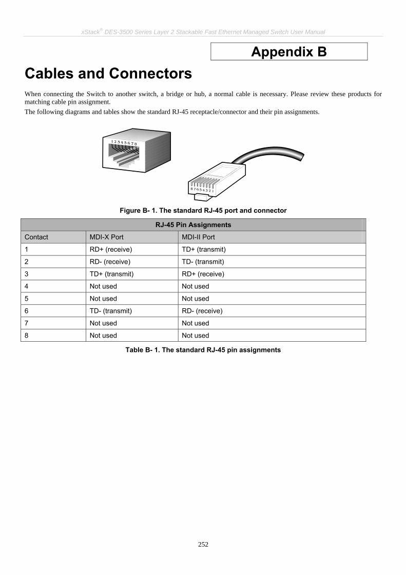
xStack® DES-3500 Series Layer 2 Stackable Fast Ethernet Managed Switch User Manual
252
Appendix B Cables and Connectors When connecting the Switch to another switch, a bridge or hub, a normal cable is necessary. Please review these products for matching cable pin assignment. The following diagrams and tables show the standard RJ-45 receptacle/connector and their pin assignments.
Figure B- 1. The standard RJ-45 port and connector
RJ-45 Pin Assignments
Contact MDI-X Port MDI-II Port
1 RD+ (receive) TD+ (transmit)
2 RD- (receive) TD- (transmit)
3 TD+ (transmit) RD+ (receive)
4 Not used Not used
5 Not used Not used
6 TD- (transmit) RD- (receive)
7 Not used Not used
8 Not used Not used
Table B- 1. The standard RJ-45 pin assignments
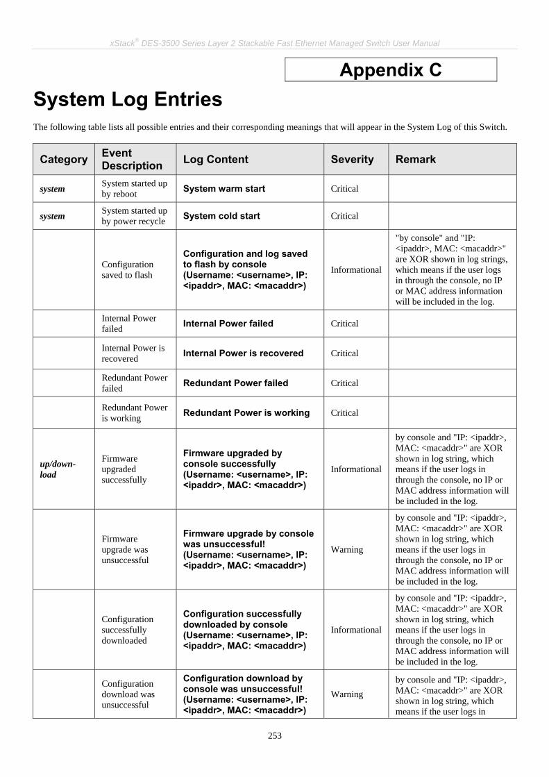
xStack® DES-3500 Series Layer 2 Stackable Fast Ethernet Managed Switch User Manual
253
Appendix C System Log Entries The following table lists all possible entries and their corresponding meanings that will appear in the System Log of this Switch.
Category Event Description Log Content Severity Remark
system System started up by reboot System warm start Critical
system System started up by power recycle System cold start Critical
Configuration saved to flash
Configuration and log saved to flash by console (Username: <username>, IP: <ipaddr>, MAC: <macaddr>)
Informational
"by console" and "IP: <ipaddr>, MAC: <macaddr>" are XOR shown in log strings, which means if the user logs in through the console, no IP or MAC address information will be included in the log.
Internal Power failed Internal Power failed Critical
Internal Power is recovered Internal Power is recovered Critical
Redundant Power failed Redundant Power failed Critical
Redundant Power is working Redundant Power is working Critical
up/down-load
Firmware upgraded successfully
Firmware upgraded by console successfully (Username: <username>, IP: <ipaddr>, MAC: <macaddr>)
Informational
by console and "IP: <ipaddr>, MAC: <macaddr>" are XOR shown in log string, which means if the user logs in through the console, no IP or MAC address information will be included in the log.
Firmware upgrade was unsuccessful
Firmware upgrade by console was unsuccessful! (Username: <username>, IP: <ipaddr>, MAC: <macaddr>)
Warning
by console and "IP: <ipaddr>, MAC: <macaddr>" are XOR shown in log string, which means if the user logs in through the console, no IP or MAC address information will be included in the log.
Configuration successfully downloaded
Configuration successfully downloaded by console (Username: <username>, IP: <ipaddr>, MAC: <macaddr>)
Informational
by console and "IP: <ipaddr>, MAC: <macaddr>" are XOR shown in log string, which means if the user logs in through the console, no IP or MAC address information will be included in the log.
Configuration download was unsuccessful
Configuration download by console was unsuccessful! (Username: <username>, IP: <ipaddr>, MAC: <macaddr>)
Warning by console and "IP: <ipaddr>, MAC: <macaddr>" are XOR shown in log string, which means if the user logs in

xStack® DES-3500 Series Layer 2 Stackable Fast Ethernet Managed Switch User Manual
254
Category Event Description Log Content Severity Remark
through the console, no IP or MAC address information will be included in the log.
Configuration successfully uploaded
Configuration successfully uploaded by console (Username: <username>, IP: <ipaddr>, MAC: <macaddr>)
Informational
by console and "IP: <ipaddr>, MAC: <macaddr>" are XOR shown in log string, which means if the user logs in through the console, no IP or MAC address information will be included in the log.
Configuration upload was unsuccessful
Configuration upload by console was unsuccessful! (Username: <username>, IP: <ipaddr>, MAC: <macaddr>)
Warning
by console and "IP: <ipaddr>, MAC: <macaddr>" are XOR shown in log string, which means if the user logs in through the console, no IP or MAC address information will be included in the log.
Log message successfully uploaded
Log message successfully uploaded by console (Username: <username>, IP: <ipaddr>, MAC: <macaddr>)
Informational
by console and "IP: <ipaddr>, MAC: <macaddr>" are XOR shown in log string, which means if the user logs in through the console, no IP or MAC address information will be included in the log.
Log message upload was unsuccessful
Log message upload by console was unsuccessful! (Username: <username>, IP: <ipaddr>, MAC: <macaddr>)
Warning
by console and "IP: <ipaddr>, MAC: <macaddr>" are XOR shown in log string, which means if the user logs in through the console, no IP or MAC address information will be included in the log.
Interface Port link up Port <portNum> link up, <link state> Informational Port link state (ex: , 100Mbps
FULL duplex)
Port link down Port <portNum> link down Informational
Console Successful login through Console
Successful login through Console (Username: <username>)
Informational
If the user logs in through the console, no IP or MAC address information will be included in the log.
Login failed through Console
Login failed through Console (Username: <username>) Warning
If the user logs in through the console, no IP or MAC address information will be included in the log.
Logout through Console
Logout through Console (Username: <username>) Informational
If the user logs in through the console, no IP or MAC address information will be included in the log.
Console session timed out
Console session timed out (Username: <username>) Informational
If the user logs in through the console, no IP or MAC address information will be included in the log.
Web Successful login through Web
Successful login through Web (Username: <username>, IP:
Informational

xStack® DES-3500 Series Layer 2 Stackable Fast Ethernet Managed Switch User Manual
255
Category Event Description Log Content Severity Remark
<ipaddr>, MAC: <macaddr>)
Login failed through Web
Login failed through Web (Username: <username>, IP: <ipaddr>, MAC: <macaddr>)
Warning
Logout through Web
Logout through Web (Username: <username>, IP: <ipaddr>, MAC: <macaddr>)
Informational
Successful login through SSL
Successful login through Web (SSL) (Username: <string>, IP: <ip>, MAC: <mac>)
Informational
Logout through SSL
Logout through Web (SSL) (Username: <string>, IP: <ip>, MAC: <mac>)
Informational
Login failed through SSL
Login failed through Web (SSL) (Username: <string>, IP: <ip>, MAC: <mac>)
Warning
Telnet Successful login through Telnet
Successful login through Telnet (Username: <username>, IP: <ipaddr>, MAC: <macaddr>)
Informational
Login failed through Telnet
Login failed through Telnet (Username: <username>, IP: <ipaddr>, MAC: <macaddr>)
Warning
Logout through Telnet
Logout through Telnet (Username: <username>, IP: <ipaddr>, MAC: <macaddr>)
Informational
Telnet session timed out
Telnet session timed out (Username: <username>, IP: <ipaddr>, MAC: <macaddr>)
Informational
SNMP SNMP request received with invalid community string
SNMP request received from <ipAddress> with invalid community string!
Informational
STP Topology changed Topology changed Informational
New Root selected New Root selected Informational
BPDU Loop Back on port
BPDU Loop Back on Port <portNum> Warning
Spanning Tree Protocol is enabled
Spanning Tree Protocol is enabled Informational
Spanning Tree Protocol is disabled
Spanning Tree Protocol is disabled Informational
SSH Successful login through SSH
Successful login through SSH (Username: <username>, IP: <ipaddr>, MAC: <macaddr>)
Informational

xStack® DES-3500 Series Layer 2 Stackable Fast Ethernet Managed Switch User Manual
256
Category Event Description Log Content Severity Remark
Login failed through SSH
Login failed through SSH (Username: <username>, IP: <ipaddr>, MAC: <macaddr>)
Warning
Logout through SSH
Logout through SSH (Username: <username>, IP: <ipaddr>, MAC: <macaddr>)
Informational
SSH session timed out
SSH session timed out (Username: <username>, IP: <ipaddr>, MAC: <macaddr>)
Informational
Enable SSH server SSH server is enabled Informational
Disable SSH server SSH server is disabled Informational
AAA Authentication Policy is enabled
Authentication Policy is enabled (Module: AAA) Informational
Authentication Policy is disabled
Authentication Policy is disabled (Module: AAA) Informational
Successful login through Console authenticated by AAA local method
Successful login through Console authenticated by AAA local method (Username: <username>)
Informational
Login failed through Console authenticated by AAA local method
Login failed through Console authenticated by AAA local method (Username: <username>)
Warning
Successful login through Web authenticated by AAA local method
Successful login through Web from <userIP> authenticated by AAA local method (Username: <username>, MAC: <macaddr>)
Informational
Login failed through Web authenticated by AAA local method
Login failed through Web from <userIP> authenticated by AAA local method (Username: <username>, MAC: <macaddr>)
Warning
Successful login through Web (SSL) authenticated by AAA local method
Successful login through Web (SSL) from <userIP> authenticated by AAA local method (Username: <username>, MAC: <macaddr>)
Informational
Login failed through Web (SSL) authenticated by AAA local method
Login failed through Web (SSL) from <userIP> authenticated by AAA local method (Username: <username>, MAC: <macaddr>)
Warning

xStack® DES-3500 Series Layer 2 Stackable Fast Ethernet Managed Switch User Manual
257
Category Event Description Log Content Severity Remark
Successful login through Telnet authenticated by AAA local method
Successful login through Telnet from <userIP> authenticated by AAA local method (Username: <username>, MAC: <macaddr>)
Informational
Login failed through Telnet authenticated by AAA local method
Login failed through Telnet from <userIP> authenticated by AAA local method (Username: <username>, MAC: <macaddr>)
Warning
Successful login through SSH authenticated by AAA local method
Successful login through SSH from <userIP> authenticated by AAA local method (Username: <username>, MAC: <macaddr>)
Informational
Login failed through SSH authenticated by AAA local method
Login failed through SSH from <userIP> authenticated by AAA local method (Username: <username>, MAC: <macaddr>)
Warning
Successful login through Console authenticated by AAA none method
Successful login through Console authenticated by AAA none method (Username: <username>)
Informational
Successful login through Web authenticated by AAA none method
Successful login through Web from <userIP> authenticated by AAA none method (Username: <username>, MAC: <macaddr>)
Informational
Successful login through Web (SSL) authenticated by AAA none method
Successful login through Web (SSL) from <userIP> authenticated by AAA none method (Username: <username>, MAC: <macaddr>)
Informational
Successful login through Telnet authenticated by AAA none method
Successful login through Telnet from <userIP> authenticated by AAA none method (Username: <username>, MAC: <macaddr>)
Informational
Successful login through SSH authenticated by AAA none method
Successful login through SSH from <userIP> authenticated by AAA none method (Username: <username>, MAC: <macaddr>)
Informational
Successful login through Console authenticated by AAA server
Successful login through Console authenticated by AAA server <serverIP> (Username: <username>)
Informational
If the user logs in through the console, no IP or MAC address information will be included in the log.

xStack® DES-3500 Series Layer 2 Stackable Fast Ethernet Managed Switch User Manual
258
Category Event Description Log Content Severity Remark
Login failed through Console authenticated by AAA server
Login failed through Console authenticated by AAA server <serverIP> (Username: <username>)
Warning There are no IP and MAC if login by console.
Login failed through Console due to AAA server timeout or improper configuration
Login failed through Console due to AAA server timeout or improper configuration (Username: <username>)
Warning
Successful login through Web authenticated by AAA server
Successful login through Web from <userIP> authenticated by AAA server <serverIP> (Username: <username>, MAC: <macaddr>)
Informational
Login failed through Web authenticated by AAA server
Login failed through Web from <userIP> authenticated by AAA server <serverIP> (Username: <username>, MAC: <macaddr>)
Warning
Login failed through Web due to AAA server timeout or improper configuration
Login failed through Web from <userIP> due to AAA server timeout or improper configuration (Username: <username>, MAC: <macaddr>)
Warning
Successful login through Web (SSL) authenticated by AAA server
Successful login through Web (SSL) from <userIP> authenticated by AAA server <serverIP> (Username: <username>, MAC: <macaddr>)
Informational
Login failed through Web (SSL) authenticated by AAA server
Login failed through Web (SSL) from <userIP> authenticated by AAA server <serverIP> (Username: <username>, MAC: <macaddr>)
Warning
Login failed through Web (SSL) due to AAA server timeout or improper configuration
Login failed through Web(SSL) from <userIP> due to AAA server timeout or improper configuration (Username: <username>, MAC: <macaddr>)
Warning
Successful login through Telnet authenticated by AAA server
Successful login through Telnet from <userIP> authenticated by AAA server <serverIP> (Username: <username>, MAC: <macaddr>)
Informational
Login failed through Telnet authenticated by
Login failed through Telnet from <userIP> authenticated by AAA server <serverIP>
Warning

xStack® DES-3500 Series Layer 2 Stackable Fast Ethernet Managed Switch User Manual
259
Category Event Description Log Content Severity Remark
AAA server (Username: <username>, MAC: <macaddr>)
Login failed through Telnet due to AAA server timeout or improper configuration
Login failed through Telnet from <userIP> due to AAA server timeout or improper configuration (Username: <username>, MAC: <macaddr>)
Warning
Successful login through SSH authenticated by AAA server
Successful login through SSH from <userIP> authenticated by AAA server <serverIP> (Username: <username>, MAC: <macaddr>)
Informational
Login failed through SSH authenticated by AAA server
Login failed through SSH from <userIP> authenticated by AAA server <serverIP> (Username: <username>, MAC: <macaddr>)
Warning
Login failed through SSH due to AAA server timeout or improper configuration
Login failed through SSH from <userIP> due to AAA server timeout or improper configuration (Username: <username>, MAC: <macaddr>)
Warning
Successful Enable Admin through Console authenticated by AAA local_enable method
Successful Enable Admin through Console authenticated by AAA local_enable method (Username: <username>)
Informational
Enable Admin failed through Console authenticated by AAA local_enable method
Enable Admin failed through Console authenticated by AAA local_enable method (Username: <username>)
Warning
Successful Enable Admin through Web authenticated by AAA local_enable method
Successful Enable Admin through Web from <userIP> authenticated by AAA local_enable method (Username: <username>, MAC: <macaddr>)
Informational
Enable Admin failed through Web authenticated by AAA local_enable method
Enable Admin failed through Web from <userIP> authenticated by AAA local_enable method (Username: <username>, MAC: <macaddr>)
Warning

xStack® DES-3500 Series Layer 2 Stackable Fast Ethernet Managed Switch User Manual
260
Category Event Description Log Content Severity Remark
Successful Enable Admin through Web (SSL) authenticated by AAA local_enable method
Successful Enable Admin through Web (SSL) from <userIP> authenticated by AAA local_enable method (Username: <username>, MAC: <macaddr>)
Informational
Enable Admin failed through Web (SSL) authenticated by AAA local_enable method
Enable Admin failed through Web (SSL) from <userIP> authenticated by AAA local_enable method (Username: <username>, MAC: <macaddr>)
Warning
Successful Enable Admin through Telnet authenticated by AAA local_enable method
Successful Enable Admin through Telnet from <userIP> authenticated by AAA local_enable method (Username: <username>, MAC: <macaddr>)
Informational
Enable Admin failed through Telnet authenticated by AAA local_enable method
Enable Admin failed through Telnet from <userIP> authenticated by AAA local_enable method (Username: <username>, MAC: <macaddr>)
Warning
Successful Enable Admin through SSH authenticated by AAA local_enable method
Successful Enable Admin through SSH from <userIP> authenticated by AAA local_enable method (Username: <username>, MAC: <macaddr>)
Informational
Enable Admin failed through SSH authenticated by AAA local_enable method
Enable Admin failed through <Telnet or Web or SSH> from <userIP> authenticated by AAA local_enable method (Username: <username>, MAC: <macaddr>)
Warning
Successful Enable Admin through Console authenticated by AAA none method
Successful Enable Admin through Console authenticated by AAA none method (Username: <username>)
Informational
Successful Enable Admin through Web authenticated by AAA none method
Successful Enable Admin through Web from <userIP> authenticated by AAA none method (Username: <username>, MAC: <macaddr>)
Informational

xStack® DES-3500 Series Layer 2 Stackable Fast Ethernet Managed Switch User Manual
261
Category Event Description Log Content Severity Remark
Successful Enable Admin through Web (SSL) authenticated by AAA none method
Successful Enable Admin through Web (SSL) from <userIP> authenticated by AAA none method (Username: <username>, MAC: <macaddr>)
Informational
Successful Enable Admin through Telnet authenticated by AAA none method
Successful Enable Admin through Telnet from <userIP> authenticated by AAA none method (Username: <username>, MAC: <macaddr>)
Informational
Successful Enable Admin through SSH authenticated by AAA none method
Successful Enable Admin through SSH from <userIP> authenticated by AAA none method (Username: <username>, MAC: <macaddr>)
Informational
Successful Enable Admin through Console authenticated by AAA server
Successful Enable Admin through Console authenticated by AAA server <serverIP> (Username: <username>)
Informational
Enable Admin failed through Console authenticated by AAA server
Enable Admin failed through Console authenticated by AAA server <serverIP> (Username: <username>)
Warning
Enable Admin failed through Console due to AAA server timeout or improper configuration
Enable Admin failed through Console due to AAA server timeout or improper configuration (Username: <username>)
Warning
Successful Enable Admin through Web authenticated by AAA server
Successful Enable Admin through Web from <userIP> authenticated by AAA server <serverIP> (Username: <username>, MAC: <macaddr>)
Informational
Enable Admin failed through Web authenticated by AAA server
Enable Admin failed through Web from <userIP> authenticated by AAA server <serverIP> (Username: <username>, MAC: <macaddr>)
Warning
Enable Admin failed through Web due to AAA server timeout or improper configuration
Enable Admin failed through Web from <userIP> due to AAA server timeout or improper configuration (Username: <username>, MAC: <macaddr>)
Warning

xStack® DES-3500 Series Layer 2 Stackable Fast Ethernet Managed Switch User Manual
262
Category Event Description Log Content Severity Remark
Successful Enable Admin through Web (SSL) authenticated by AAA server
Successful Enable Admin through Web (SSL) from <userIP> authenticated by AAA server <serverIP> (Username: <username>, MAC: <macaddr>)
Informational
Enable Admin failed through Web (SSL) authenticated by AAA server
Enable Admin failed through Web (SSL) from <userIP> authenticated by AAA server <serverIP> (Username: <username>, MAC: <macaddr>)
Warning
Enable Admin failed through Web (SSL) due to AAA server timeout or improper configuration
Enable Admin failed through Web (SSL) from <userIP> due to AAA server timeout or improper configuration (Username: <username>, MAC: <macaddr>)
Warning
Successful Enable Admin through Telnet authenticated by AAA server
Successful Enable Admin through Telnet from <userIP> authenticated by AAA server <serverIP> (Username: <username>, MAC: <macaddr>)
Informational
Enable Admin failed through Telnet authenticated by AAA server
Enable Admin failed through Telnet from <userIP> authenticated by AAA server <serverIP> (Username: <username>, MAC: <macaddr>)
Warning
Enable Admin failed through Telnet due to AAA server timeout or improper configuration
Enable Admin failed through Telnet from <userIP> due to AAA server timeout or improper configuration (Username: <username>, MAC: <macaddr>)
Warning
Successful Enable Admin through SSH authenticated by AAA server
Successful Enable Admin through SSH from <userIP> authenticated by AAA server <serverIP> (Username: <username>, MAC: <macaddr>)
Informational
Enable Admin failed through SSH authenticated by AAA server
Enable Admin failed through SSH from <userIP> authenticated by AAA server <serverIP> (Username: <username>, MAC: <macaddr>)
Warning
Enable Admin failed through SSH due to AAA server timeout or improper
Enable Admin failed through SSH from <userIP> due to AAA server timeout or improper configuration (Username: <username>,
Warning

xStack® DES-3500 Series Layer 2 Stackable Fast Ethernet Managed Switch User Manual
263
Category Event Description Log Content Severity Remark
configuration MAC: <macaddr>)
AAA server timed out
AAA server <serverIP> (Protocol: <protocol>) connection failed
Warning <protocol> is one of TACACS, XTACACS, TACACS+ or RADIUS
Port Security
port security has reached its maximum learning size and will not learn any new addresses
Port security violation (Port: <portNum>, MAC: <macaddr>) Warning
IP-MAC-PORT Binding
Unauthenticated IP address discarded by IP mac port binding
Unauthenticated IP-MAC address and discarded by ip mac port binding (IP: <ipaddr>, MAC: <macaddr>, Port <portNum>)
Warning
Safeguard Engine
Safeguard Engine is in normal mode
SafeGuard Engine enters NORMAL mode Informational
Safeguard Engine is in filtering packet mode
Safeguard Engine enters EXHAUSTED mode Warning
Packet Storm
Broadcast storm occurence
Broadcast storm is occurring (port: <id>) Warning
Broadcast storm has cleared
Broadcast storm has cleared (port: <id>) Informational
Multicast storm occurence
Multicast storm is occurring (port: <id>) Warning
Multicast storm has cleared
Multicast storm has cleared (port: <id>) Informational
Security
Packet received containing a MAC address identical to the MAC address of the device’s interface
Possible spoofing attack from <mac> port <u16> Critical

xStack® DES-3500 Series Layer 2 Stackable Fast Ethernet Managed Switch User Manual
264
Appendix D Cable Lengths Use the following table to as a guide for the maximum cable lengths.
Standard Media Type Maximum Distance
Mini-GBIC 1000BASE-LX, Single-mode fiber module 1000BASE-SX, Multi-mode fiber module 1000BASE-LHX, Single-mode fiber module 1000BASE-ZX, Single-mode fiber module
10km 550m 40km 80km
1000BASE-T Category 5e UTP Cable Category 5 UTP Cable (1000 Mbps)
100m
100BASE-TX Category 5 UTP Cable (100 Mbps) 100m
10BASE-T Category 3 UTP Cable (10 Mbps) 100m

xStack® DES-3500 Series Layer 2 Stackable Fast Ethernet Managed Switch User Manual
265
Appendix E
Mitigating ARP Spoofing Attacks Using Packet Content ACL Address Resolution Protocol (ARP) is the standard method for finding a host's hardware address (MAC address) when only its IP address is known. This protocol is vulnerable because it can spoof the IP and MAC information in the ARP packets to attack a LAN (known as ARP spoofing). This document is intended to introduce ARP protocol, ARP spoofing attacks, and the counter measure brought by D-Link's switches to counter the ARP spoofing attack.
• How Address Resolution Protocol works
In the process of ARP, PC A will, firstly, issue an ARP request to query PC B’s MAC address. The network structure is shown in Figure-1.
Figure-1
In the mean time, PC A’s MAC address will be written into the “Sender H/W Address” and its IP address will be written into the “Sender Protocol Address” in ARP payload. As PC B’s MAC address is unknown, the “Target H/W Address” will be “00-00-00-00-00-00” while PC B’s IP address will be written into the “Target Protocol Address”, shown in Table-1.
H/W type
Protocol type
H/W address length
Protocol address length
Operation Sender H/W address
Sender protocol address
Target H/W address
Target protocol address
ARP request 00-20-5C-01-11-11 10.10.10.1 00-00-00-00-00-00 10.10.10.2
Table -1 (ARP Payload)
The ARP request will be encapsulated into Ethernet frame and sent out. As can be seen in Table-2, the “Source Address” in the Ethernet frame will be PC A’s MAC address. Since an ARP request is sent via a broadcast, the “Destination address” is in the format of an Ethernet broadcast (FF-FF-FF-FF-FF-FF).

xStack® DES-3500 Series Layer 2 Stackable Fast Ethernet Managed Switch User Manual
266
Destination address
Source address
Ether-type ARP FCS
FF-FF-FF-FF-FF-FF 00-20-5C-01-11-11
Table-2 (Ethernet frame format)
When the switch receives the frame, it will check the “Source Address” in the Ethernet frame’s header. If the address is not in its Forwarding Table, the switch will learn PC A’s MAC and the associated port into its Forwarding Table.
Port1 00-20-5C-01-11-11
In addition, when the switch receives the broadcast ARP request, it will flood the frame to all ports except the source port, port 1 (see Figure -2).
Figure - 2
When the switch floods the frame of ARP requests to the network, all PCs will receive and examine the frame but only PC B will reply to the query as the destination IP address of PC B matches (see Figure-3).
Figure-3
Forwarding Table

xStack® DES-3500 Series Layer 2 Stackable Fast Ethernet Managed Switch User Manual
267
When PC B replies to the ARP request, its MAC address will be written into “Target H/W Address” in the ARP payload shown in Table-3. The ARP reply will be then encapsulated into the Ethernet frame again and sent back to the sender. The ARP reply is in a form of Unicast communication.
H/W type
Protocol type
H/W address length
Protocol address length
Operation
Sender H/W address
Sender protocol address
Target H/W address
Target protocol address
ARP reply 00-20-5C-01-11-11 10.10.10.1 00-20-5C-01-22-22 10.10.10.2
Table – 3 (ARP Payload)
When PC B replies the query, the “Destination Address” in the Ethernet frame will be changed to PC A’s MAC address. The “Source Address” will be changed to PC B’s MAC address (see Table-4).
Destination address Source address
Ether-type ARP FCS
00-20-5C-01-11-11 00-20-5C-01-22-22
Table – 4 (Ethernet frame format)
The switch will also examine the “Source Address” of the Ethernet frame and find that the address is not in the Forwarding Table. The switch will learn PC B’s MAC and update its Forwarding Table.
Port1 00-20-5C-01-11-11 Port2 00-20-5C-01-22-22
Forwarding Table
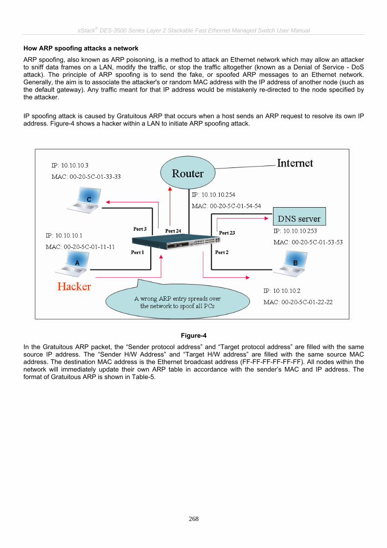
xStack® DES-3500 Series Layer 2 Stackable Fast Ethernet Managed Switch User Manual
268
How ARP spoofing attacks a network
ARP spoofing, also known as ARP poisoning, is a method to attack an Ethernet network which may allow an attacker to sniff data frames on a LAN, modify the traffic, or stop the traffic altogether (known as a Denial of Service - DoS attack). The principle of ARP spoofing is to send the fake, or spoofed ARP messages to an Ethernet network. Generally, the aim is to associate the attacker's or random MAC address with the IP address of another node (such as the default gateway). Any traffic meant for that IP address would be mistakenly re-directed to the node specified by the attacker. IP spoofing attack is caused by Gratuitous ARP that occurs when a host sends an ARP request to resolve its own IP address. Figure-4 shows a hacker within a LAN to initiate ARP spoofing attack.
Figure-4
In the Gratuitous ARP packet, the “Sender protocol address” and “Target protocol address” are filled with the same source IP address. The “Sender H/W Address” and “Target H/W address” are filled with the same source MAC address. The destination MAC address is the Ethernet broadcast address (FF-FF-FF-FF-FF-FF). All nodes within the network will immediately update their own ARP table in accordance with the sender’s MAC and IP address. The format of Gratuitous ARP is shown in Table-5.

xStack® DES-3500 Series Layer 2 Stackable Fast Ethernet Managed Switch User Manual
269
Destination address
Source address
Ethernet type
H/W type Protocol type
H/W address length
Protocol address length
Operation Sender H/W address
Sender protocol address
Target H/W address
Target protocol address
(6-byte) (6-byte) (2-byte) (2-byte) (2-byte) (1-byte) (1-byte) (2-byte) (6-byte) (4-byte) (6-byte) (4-byte)
FF-FF-FF-FF-FF-FF 00-20-5C-01-11-11 806 ARP reply 00-20-5C-01-11-11 10.10.10.254 00-20-5C-01-11-11 10.10.10.254
Table-5
A common DoS attack today can be done by associating a nonexistent or specified MAC address to the IP address of the network’s default gateway. The malicious attacker only needs to broadcast ONE Gratuitous ARP to the network claiming it is the gateway so that the whole network operation will be turned down as all packets to the Internet will be directed to the wrong node. Likewise, the attacker can either choose to forward the traffic to the actual default gateway (passive sniffing) or modify the data before forwarding it (man-in-the-middle attack). The hacker cheats the victim’s PC to think that it is a router and cheats the router to think it is the victim. As can be seen in Figure-5 all traffic will be then sniffed by the hacker but the users will not notice anything happening.
Figure-5
Gratuitous ARP Ethernet Header

xStack® DES-3500 Series Layer 2 Stackable Fast Ethernet Managed Switch User Manual
270
• Prevent ARP spoofing via packet content ACL
Concerning the common DoS attack today caused by the ARP spoofing, D-Link managed switch can effectively mitigate it via its unique Packet Content ACL. For that reason the basic ACL can only filter ARP packets based on packet type, VLAN ID, Source and Destination MAC information, there is a need for further inspections of ARP packets. To prevent ARP spoofing attack, we will demonstrate here using Packet Content ACL on DES-3526 to block the invalid ARP packets which contain fake gateway’s MAC and IP binding.
Example topology Configuration:
The configuration logic is listed below: 1. Only when the ARP matches the Source MAC address in Ethernet, the Sender MAC address and Sender IP
address in the ARP protocol can pass through the switch. (In this example, it is the gateway’s ARP.) 2. The switch will deny all other ARP packets which claim they are from the gateway’s IP. The design of Packet Content ACL on DES-3500 series enables users to inspect any offset_chunk. An offset_chunk is a 4-byte block in a HEX format which is utilized to match the individual field in an Ethernet frame. Each profile is allowed to contain up to a maximum of 4 offset_chunks. Furthermore, only one single profile of Packet Content ACL can be supported per switch. In other words, up to 16 bytes of total offset_chunks can be applied to each profile and a switch. Therefore, careful consideration is needed for planning the configuration of the valuable offset_chunks. In Table-6, you will notice that the Offset_Chunk0 starts from 127 and ends at the 128th byte. It can also be found that the offset_chunk is scratched from 1 but not zero!!!

xStack® DES-3500 Series Layer 2 Stackable Fast Ethernet Managed Switch User Manual
271
Offset Chunk
Offset Chunk0
Offset Chunk1
Offset Chunk2
Offset Chunk3
Offset Chunk4
Offset Chunk5
Offset Chunk6
Offset Chunk7
Offset Chunk8
Offset Chunk9
Offset Chunk10
Offset Chunk11
Offset Chunk12
Offset Chunk13
Offset Chunk14
Offset Chunk15
Byte 127 3 7 11 15 19 23 27 31 35 39 43 47 51 55 59
Byte 128 4 8 12 16 20 24 28 32 36 40 44 48 52 56 60
Byte 1 5 9 13 17 21 25 29 33 37 41 45 49 53 57 61
Byte 2 6 10 14 18 22 26 30 34 38 42 46 50 54 58 62
Offset Chunk
Offset Chunk15
Offset Chunk16
Offset Chunk17
Offset Chunk18
Offset Chunk19
Offset Chunk20
Offset Chunk21
Offset Chunk22
Offset Chunk23
Offset Chunk24
Offset Chunk25
Offset Chunk26
Offset Chunk27
Offset Chunk28
Offset Chunk129
Offset Chunk30
Byte 63 67 71 75 79 83 87 91 95 99 103 107 111 115 119 123
Byte 64 68 72 76 80 84 88 92 96 100 104 108 112 116 120 124
Byte 65 69 73 77 81 85 89 93 97 101 105 109 113 117 121 125
Byte 66 70 74 78 82 86 90 94 98 102 106 110 114 118 122 126
Table-6: Chunk and Packet offset Indicates a completed ARP packet contained in the Ethernet frame, which is the pattern for the calculation of packet offset. Destination address
Source address Ethernet type
H/W type Protocol type
H/W address length
Protocol address length
Operation Sender H/W address
Sender protocol address
Target H/W address
Target protocol address
(6-byte) (6-byte) (2-byte) (2-byte) (2-byte) (1-byte) (1-byte) (2-byte) (6-byte) (4-byte) (6-byte) (4-byte)
01 02 03 04 05 06 0806 0a5a5a5a
(10.90.90.90)
Table-7: A completed ARP packet contained in Ethernet frame
Ethernet Header ARP
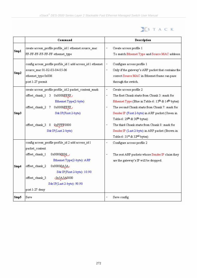
xStack® DES-3500 Series Layer 2 Stackable Fast Ethernet Managed Switch User Manual
272
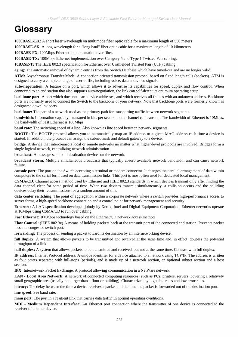
xStack® DES-3500 Series Layer 2 Stackable Fast Ethernet Managed Switch User Manual
273
Glossary 1000BASE-LX: A short laser wavelength on multimode fiber optic cable for a maximum length of 550 meters 1000BASE-SX: A long wavelength for a "long haul" fiber optic cable for a maximum length of 10 kilometers 100BASE-FX: 100Mbps Ethernet implementation over fiber. 100BASE-TX: 100Mbps Ethernet implementation over Category 5 and Type 1 Twisted Pair cabling. 10BASE-T: The IEEE 802.3 specification for Ethernet over Unshielded Twisted Pair (UTP) cabling. aging: The automatic removal of dynamic entries from the Switch Database which have timed-out and are no longer valid. ATM: Asynchronous Transfer Mode. A connection oriented transmission protocol based on fixed length cells (packets). ATM is designed to carry a complete range of user traffic, including voice, data and video signals. auto-negotiation: A feature on a port, which allows it to advertise its capabilities for speed, duplex and flow control. When connected to an end station that also supports auto-negotiation, the link can self-detect its optimum operating setup. backbone port: A port which does not learn device addresses, and which receives all frames with an unknown address. Backbone ports are normally used to connect the Switch to the backbone of your network. Note that backbone ports were formerly known as designated downlink ports. backbone: The part of a network used as the primary path for transporting traffic between network segments. bandwidth: Information capacity, measured in bits per second that a channel can transmit. The bandwidth of Ethernet is 10Mbps, the bandwidth of Fast Ethernet is 100Mbps. baud rate: The switching speed of a line. Also known as line speed between network segments. BOOTP: The BOOTP protocol allows you to automatically map an IP address to a given MAC address each time a device is started. In addition, the protocol can assign the subnet mask and default gateway to a device. bridge: A device that interconnects local or remote networks no matter what higher-level protocols are involved. Bridges form a single logical network, centralizing network administration. broadcast: A message sent to all destination devices on the network. broadcast storm: Multiple simultaneous broadcasts that typically absorb available network bandwidth and can cause network failure. console port: The port on the Switch accepting a terminal or modem connector. It changes the parallel arrangement of data within computers to the serial form used on data transmission links. This port is most often used for dedicated local management. CSMA/CD: Channel access method used by Ethernet and IEEE 802.3 standards in which devices transmit only after finding the data channel clear for some period of time. When two devices transmit simultaneously, a collision occurs and the colliding devices delay their retransmissions for a random amount of time. data center switching: The point of aggregation within a corporate network where a switch provides high-performance access to server farms, a high-speed backbone connection and a control point for network management and security. Ethernet: A LAN specification developed jointly by Xerox, Intel and Digital Equipment Corporation. Ethernet networks operate at 10Mbps using CSMA/CD to run over cabling. Fast Ethernet: 100Mbps technology based on the Ethernet/CD network access method. Flow Control: (IEEE 802.3z) A means of holding packets back at the transmit port of the connected end station. Prevents packet loss at a congested switch port. forwarding: The process of sending a packet toward its destination by an internetworking device. full duplex: A system that allows packets to be transmitted and received at the same time and, in effect, doubles the potential throughput of a link. half duplex: A system that allows packets to be transmitted and received, but not at the same time. Contrast with full duplex. IP address: Internet Protocol address. A unique identifier for a device attached to a network using TCP/IP. The address is written as four octets separated with full-stops (periods), and is made up of a network section, an optional subnet section and a host section. IPX: Internetwork Packet Exchange. A protocol allowing communication in a NetWare network. LAN - Local Area Network: A network of connected computing resources (such as PCs, printers, servers) covering a relatively small geographic area (usually not larger than a floor or building). Characterized by high data rates and low error rates. latency: The delay between the time a device receives a packet and the time the packet is forwarded out of the destination port. line speed: See baud rate. main port: The port in a resilient link that carries data traffic in normal operating conditions. MDI - Medium Dependent Interface: An Ethernet port connection where the transmitter of one device is connected to the receiver of another device.
xStack® DES-3500 Series Layer 2 Stackable Fast Ethernet Managed Switch User Manual
274
MDI-X - Medium Dependent Interface Cross-over: An Ethernet port connection where the internal transmit and receive lines are crossed. MIB - Management Information Base: Stores a device's management characteristics and parameters. MIBs are used by the Simple Network Management Protocol (SNMP) to contain attributes of their managed systems. The Switch contains its own internal MIB. multicast: Single packets copied to a specific subset of network addresses. These addresses are specified in the destination-address field of the packet. protocol: A set of rules for communication between devices on a network. The rules dictate format, timing, sequencing and error control. resilient link: A pair of ports that can be configured so that one will take over data transmission should the other fail. See also main port and standby port. RJ-45: Standard 8-wire connectors for IEEE 802.3 10BASE-T networks. RMON: Remote Monitoring. A subset of SNMP MIB II that allows monitoring and management capabilities by addressing up to ten different groups of information. RPS - Redundant Power System: A device that provides a backup source of power when connected to the Switch. server farm: A cluster of servers in a centralized location serving a large user population. SLIP - Serial Line Internet Protocol: A protocol, which allows IP to run over a serial line connection. SNMP - Simple Network Management Protocol: A protocol originally designed to be used in managing TCP/IP internets. SNMP is presently implemented on a wide range of computers and networking equipment and may be used to manage many aspects of network and end station operation. Spanning Tree Protocol (STP): A bridge-based system for providing fault tolerance on networks. STP works by allowing you to implement parallel paths for network traffic, and ensure that redundant paths are disabled when the main paths are operational and enabled if the main paths fail. stack: A group of network devices that are integrated to form a single logical device. standby port: The port in a resilient link that will take over data transmission if the main port in the link fails. switch: A device, which filters, forwards and floods packets based on the packet's destination address. The switch learns the addresses associated with each switch port and builds tables based on this information to be used for the switching decision. TCP/IP: A layered set of communications protocols providing Telnet terminal emulation, FTP file transfer, and other services for communication among a wide range of computer equipment. telnet: A TCP/IP application protocol that provides virtual terminal service, letting a user log in to another computer system and access a host as if the user were connected directly to the host. TFTP - Trivial File Transfer Protocol: Allows you to transfer files (such as software upgrades) from a remote device using your switch's local management capabilities. UDP - User Datagram Protocol: An Internet standard protocol that allows an application program on one device to send a datagram to an application program on another device. VLAN - Virtual LAN: A group of location- and topology-independent devices that communicate as if they are on a common physical LAN. VLT - Virtual LAN Trunk: A Switch-to-Switch link which carries traffic for all the VLANs on each Switch. VT100: A type of terminal that uses ASCII characters. VT100 screens have a text-based appearance.

275
FCC Warning
This equipment has been tested and found to comply with the limits for a Class A digital device, pursuant to Part 15 of the FCC Rules. These limits are designed to provide reasonable protection against harmful interference when the equipment is operated in a commercial environment. This equipment generates, uses, and can radiate radio frequency energy and, if not installed and used in accordance with this manual, may cause harmful interference to radio communications. Operation of this equipment in a residential area is likely to cause harmful interference in which case the user will be required to correct the interference at his own expense. CE Mark Warning
This is a Class A product. In a domestic environment, this product may cause radio interference in which case the user may be required to take adequate measures.
Warnung!
Dies ist ein Produkt der Klasse A. Im Wohnbereich kann dieses Produkt Funkstoerungen verursachen. In diesem Fall kann vom Benutzer verlangt werden, angemessene Massnahmen zu ergreifen.
Precaución!
Este es un producto de Clase A. En un entorno doméstico, puede causar interferencias de radio, en cuyo case, puede requerirse al usuario para que adopte las medidas adecuadas.
Attention!
Ceci est un produit de classe A. Dans un environnement domestique, ce produit pourrait causer des interférences radio, auquel cas l`utilisateur devrait prendre les mesures adéquates.
Attenzione! Il presente prodotto appartiene alla classe A. Se utilizzato in ambiente domestico il prodotto può causare interferenze radio, nel cui caso è possibile che l`utente debba assumere provvedimenti adeguati. BSMI Warning

276
Warrenties/Registration LIMITED WARRANTY D-Link provides this limited warranty for its product only to the person or entity who originally purchased the product from D-Link or its authorized reseller or distributor. D-Link would fulfill the warranty obligation according to the local warranty policy in which you purchased our products. Limited Hardware Warranty: D-Link warrants that the hardware portion of the D-Link products described below (“Hardware”) will be free from material defects in workmanship and materials from the date of original retail purchase of the Hardware, for the period set forth below applicable to the product type (“Warranty Period”) if the Hardware is used and serviced in accordance with applicable documentation; provided that a completed Registration Card is returned to an Authorized D-Link Service Office within ninety (90) days after the date of original retail purchase of the Hardware. If a completed Registration Card is not received by an authorized D-Link Service Office within such ninety (90) period, then the Warranty Period shall be ninety (90) days from the date of purchase.
Product Type Warranty Period
Product (including Power Supplies and Fans) One (1) Year Spare parts and pare kits Ninety (90) days
D-Link’s sole obligation shall be to repair or replace the defective Hardware at no charge to the original owner. Such repair or replacement will be rendered by D-Link at an Authorized D-Link Service Office. The replacement Hardware need not be new or of an identical make, model or part; D-Link may in its discretion may replace the defective Hardware (or any part thereof) with any reconditioned product that D-Link reasonably determines is substantially equivalent (or superior) in all material respects to the defective Hardware. The Warranty Period shall extend for an additional ninety (90) days after any repaired or replaced Hardware is delivered. If a material defect is incapable of correction, or if D-Link determines in its sole discretion that it is not practical to repair or replace the defective Hardware, the price paid by the original purchaser for the defective Hardware will be refunded by D-Link upon return to D-Link of the defective Hardware. All Hardware (or part thereof) that is replaced by D-Link, or for which the purchase price is refunded, shall become the property of D-Link upon replacement or refund. Limited Software Warranty: D-Link warrants that the software portion of the product (“Software”) will substantially conform to D-Link’s then current functional specifications for the Software, as set forth in the applicable documentation, from the date of original delivery of the Software for a period of ninety (90) days (“Warranty Period”), if the Software is properly installed on approved hardware and operated as contemplated in its documentation. D-Link further warrants that, during the Warranty Period, the magnetic media on which D-Link delivers the Software will be free of physical defects. D-Link’s sole obligation shall be to replace the non-conforming Software (or defective media) with software that substantially conforms to D-Link’s functional specifications for the Software. Except as otherwise agreed by D-Link in writing, the replacement Software is provided only to the original licensee, and is subject to the terms and conditions of the license granted by D-Link for the Software. The Warranty Period shall extend for an additional ninety (90) days after any replacement Software is delivered. If a material non-conformance is incapable of correction, or if D-Link determines in its sole discretion that it is not practical to replace the non-conforming Software, the price paid by the original licensee for the non-conforming Software will be refunded by D-Link; provided that the non-conforming Software (and all copies thereof) is first returned to D-Link. The license granted respecting any Software for which a refund is given automatically terminates. What You Must Do For Warranty Service: Registration Card. The Registration Card provided at the back of this manual must be completed and returned to an Authorized D-Link Service Office for each D-Link product within ninety (90) days after the product is purchased and/or licensed. The addresses/telephone/fax list of the nearest Authorized D-Link Service Office is provided in the back of this manual. FAILURE TO PROPERLY COMPLETE AND TIMELY RETURN THE REGISTRATION CARD MAY AFFECT THE WARRANTY FOR THIS PRODUCT. Submitting A Claim. Any claim under this limited warranty must be submitted in writing before the end of the Warranty Period to an Authorized D-Link Service Office. The claim must include a written description of the Hardware defect or Software

277
nonconformance in sufficient detail to allow D-Link to confirm the same. The original product owner must obtain a Return Material Authorization (RMA) number from the Authorized D-Link Service Office and, if requested, provide written proof of purchase of the product (such as a copy of the dated purchase invoice for the product) before the warranty service is provided. After an RMA number is issued, the defective product must be packaged securely in the original or other suitable shipping package to ensure that it will not be damaged in transit, and the RMA number must be prominently marked on the outside of the package. The packaged product shall be insured and shipped to Authorized D-Link Service Office with all shipping costs prepaid. D-Link may reject or return any product that is not packaged and shipped in strict compliance with the foregoing requirements, or for which an RMA number is not visible from the outside of the package. The product owner agrees to pay D-Link’s reasonable handling and return shipping charges for any product that is not packaged and shipped in accordance with the foregoing requirements, or that is determined by D-Link not to be defective or non-conforming. What Is Not Covered: This limited warranty provided by D-Link does not cover: Products that have been subjected to abuse, accident, alteration, modification, tampering, negligence, misuse, faulty installation, lack of reasonable care, repair or service in any way that is not contemplated in the documentation for the product, or if the model or serial number has been altered, tampered with, defaced or removed; Initial installation, installation and removal of the product for repair, and shipping costs; Operational adjustments covered in the operating manual for the product, and normal maintenance; Damage that occurs in shipment, due to act of God, failures due to power surge, and cosmetic damage; and Any hardware, software, firmware or other products or services provided by anyone other than D-Link. Disclaimer of Other Warranties: EXCEPT FOR THE LIMITED WARRANTY SPECIFIED HEREIN, THE PRODUCT IS PROVIDED “AS-IS” WITHOUT ANY WARRANTY OF ANY KIND INCLUDING, WITHOUT LIMITATION, ANY WARRANTY OF MERCHANTABILITY, FITNESS FOR A PARTICULAR PURPOSE AND NON-INFRINGEMENT. IF ANY IMPLIED WARRANTY CANNOT BE DISCLAIMED IN ANY TERRITORY WHERE A PRODUCT IS SOLD, THE DURATION OF SUCH IMPLIED WARRANTY SHALL BE LIMITED TO NINETY (90) DAYS. EXCEPT AS EXPRESSLY COVERED UNDER THE LIMITED WARRANTY PROVIDED HEREIN, THE ENTIRE RISK AS TO THE QUALITY, SELECTION AND PERFORMANCE OF THE PRODUCT IS WITH THE PURCHASER OF THE PRODUCT. Limitation of Liability: TO THE MAXIMUM EXTENT PERMITTED BY LAW, D-LINK IS NOT LIABLE UNDER ANY CONTRACT, NEGLIGENCE, STRICT LIABILITY OR OTHER LEGAL OR EQUITABLE THEORY FOR ANY LOSS OF USE OF THE PRODUCT, INCONVENIENCE OR DAMAGES OF ANY CHARACTER, WHETHER DIRECT, SPECIAL, INCIDENTAL OR CONSEQUENTIAL (INCLUDING, BUT NOT LIMITED TO, DAMAGES FOR LOSS OF GOODWILL, WORK STOPPAGE, COMPUTER FAILURE OR MALFUNCTION, LOSS OF INFORMATION OR DATA CONTAINED IN, STORED ON, OR INTEGRATED WITH ANY PRODUCT RETURNED TO D-LINK FOR WARRANTY SERVICE) RESULTING FROM THE USE OF THE PRODUCT, RELATING TO WARRANTY SERVICE, OR ARISING OUT OF ANY BREACH OF THIS LIMITED WARRANTY, EVEN IF D-LINK HAS BEEN ADVISED OF THE POSSIBILITY OF SUCH DAMAGES. THE SOLE REMEDY FOR A BREACH OF THE FOREGOING LIMITED WARRANTY IS REPAIR, REPLACEMENT OR REFUND OF THE DEFECTIVE OR NON-CONFORMING PRODUCT. GOVERNING LAW: This Limited Warranty shall be governed by the laws of the state of California. Some states do not allow exclusion or limitation of incidental or consequential damages, or limitations on how long an implied warranty lasts, so the foregoing limitations and exclusions may not apply. This limited warranty provides specific legal rights and the product owner may also have other rights which vary from state to state. Trademarks Copyright .2008 D-Link Corporation. Contents subject to change without prior notice. D-Link is a registered trademark of D-Link Corporation/D-Link Systems, Inc. All other trademarks belong to their respective proprietors.

278
Copyright Statement No part of this publication may be reproduced in any form or by any means or used to make any derivative such as translation, transformation, or adaptation without permission from D-Link Corporation/D-Link Systems Inc., as stipulated by the United States Copyright Act of 1976.
FCC Warning This equipment has been tested and found to comply with the limits for a Class A digital device, pursuant to Part 15 of the FCC Rules. These limits are designed to provide reasonable protection against harmful interference when the equipment is operated in a commercial environment. This equipment generates, uses, and can radiate radio frequency energy and, if not installed and used in accordance with this manual, may cause harmful interfe rence to radio communications. Operation of this equipment in a residential area is likely to cause harmful interference in which case the user will be required to correct the interference at his own expense.

Subject to the terms and conditions set forth herein, D-Link Systems, Inc. (“D-Link”) provides this Limited Warranty: • Only to the person or entity that originally purchased the product from D-Link or its authorized reseller or distributor, and • Only for products purchased and delivered within the fifty states of the United States, the District of Columbia, U.S. Possessions or
Protectorates, U.S. Military Installations, or addresses with an APO or FPO. Limited Warranty: D-Link warrants that the hardware portion of the D-Link product described below (“Hardware”) will be free from material defects in workmanship and materials under normal use from the date of original retail purchase of the product, for the period set forth below (“Warranty Period”), except as otherwise stated herein. Limited Lifetime Warranty for the product is defined as follows: • Hardware: For as long as the original customer/end user owns the product, or five (5) years after product discontinuance, whichever
occurs first (excluding power supplies and fans) • Power supplies and fans: Three (3) Year • Spare parts and spare kits: Ninety (90) days The customer's sole and exclusive remedy and the entire liability of D-Link and its suppliers under this Limited Warranty will be, at D-Link’s option, to repair or replace the defective Hardware during the Warranty Period at no charge to the original owner or to refund the actual purchase price paid. Any repair or replacement will be rendered by D-Link at an Authorized D-Link Service Office. The replacement hardware need not be new or have an identical make, model or part. D-Link may, at its option, replace the defective Hardware or any part thereof with any reconditioned product that D-Link reasonably determines is substantially equivalent (or superior) in all material respects to the defective Hardware. Repaired or replacement hardware will be warranted for the remainder of the original Warranty Period or ninety (90) days, whichever is longer, and is subject to the same limitations and exclusions. If a material defect is incapable of correction, or if D-Link determines that it is not practical to repair or replace the defective Hardware, the actual price paid by the original purchaser for the defective Hardware will be refunded by D-Link upon return to D-Link of the defective Hardware. All Hardware or part thereof that is replaced by D-Link, or for which the purchase price is refunded, shall become the property of D-Link upon replacement or refund. Limited Software Warranty: D-Link warrants that the software portion of the product (“Software”) will substantially conform to D-Link’s then current functional specifications for the Software, as set forth in the applicable documentation, from the date of original retail purchase of the Software for a period of ninety (90) days (“Software Warranty Period”), provided that the Software is properly installed on approved hardware and operated as contemplated in its documentation. D-Link further warrants that, during the Software Warranty Period, the magnetic media on which D-Link delivers the Software will be free of physical defects. The customer's sole and exclusive remedy and the entire liability of D-Link and its suppliers under this Limited Warranty will be, at D-Link’s option, to replace the non-conforming Software (or defective media) with software that substantially conforms to D-Link’s functional specifications for the Software or to refund the portion of the actual purchase price paid that is attributable to the Software. Except as otherwise agreed by D-Link in writing, the replacement Software is provided only to the original licensee, and is subject to the terms and conditions of the license granted by D-Link for the Software. Replacement Software will be warranted for the remainder of the original Warranty Period and is subject to the same limitations and exclusions. If a material non-conformance is incapable of correction, or if D-Link determines in its sole discretion that it is not practical to replace the non-conforming Software, the price paid by the original licensee for the non-conforming Software will be refunded by D-Link; provided that the non-conforming Software (and all copies thereof) is first returned to D-Link. The license granted respecting any Software for which a refund is given automatically terminates. Non-Applicability of Warranty: The Limited Warranty provided hereunder for Hardware and Software portions of D-Link's products will not be applied to and does not cover any refurbished product and any product purchased through the inventory clearance or liquidation sale or other sales in which D-Link, the sellers, or the liquidators expressly disclaim their warranty obligation pertaining to the product and in that case, the product is being sold "As-Is" without any warranty whatsoever including, without limitation, the Limited Warranty as described herein, notwithstanding anything stated herein to the contrary. Submitting A Claim: The customer shall return the product to the original purchase point based on its return policy. In case the return policy period has expired and the product is within warranty, the customer shall submit a claim to D-Link as outlined below: • The customer must submit with the product as part of the claim a written description of the Hardware defect or Software nonconformance
in sufficient detail to allow D-Link to confirm the same, along with proof of purchase of the product (such as a copy of the dated purchase invoice for the product) if the product is not registered.
• The customer must obtain a Case ID Number from D-Link Technical Support at 1-877-453-5465, who will attempt to assist the customer in resolving any suspected defects with the product. If the product is considered defective, the customer must obtain a Return Material Authorization (“RMA”) number by completing the RMA form and entering the assigned Case ID Number at https://rma.dlink.com/.
• After an RMA number is issued, the defective product must be packaged securely in the original or other suitable shipping package to ensure that it will not be damaged in transit, and the RMA number must be prominently marked on the outside of the package. Do not include any manuals or accessories in the shipping package. D-Link will only replace the defective portion of the product and will not ship back any accessories.
• The customer is responsible for all in-bound shipping charges to D-Link. No Cash on Delivery (“COD”) is allowed. Products sent COD will either be rejected by D-Link or become the property of D-Link. Products shall be fully insured by the customer and shipped to D-Link Systems, Inc., 17595 Mt. Herrmann, Fountain Valley, CA 92708. D-Link will not be held responsible for any packages that are lost in transit to D-Link. The repaired or replaced packages will be shipped to the customer via UPS Ground or any common carrier selected by D-Link. Return shipping charges shall be prepaid by D-Link if you use an address in the United States, otherwise we will ship the product to you freight collect. Expedited shipping is available upon request and provided shipping charges are prepaid by the customer.
D-Link may reject or return any product that is not packaged and shipped in strict compliance with the foregoing requirements, or for which an RMA number is not visible from the outside of the package. The product owner agrees to pay D-Link’s reasonable handling and return shipping charges for any product that is not packaged and shipped in accordance with the foregoing requirements, or that is determined by D-Link not to be defective or non-conforming. What Is Not Covered: The Limited Warranty provided herein by D-Link does not cover: Products that, in D-Link’s judgment, have been subjected to abuse, accident, alteration, modification, tampering, negligence, misuse, faulty installation, lack of reasonable care, repair or service in any way that

is not contemplated in the documentation for the product, or if the model or serial number has been altered, tampered with, defaced or removed; Initial installation, installation and removal of the product for repair, and shipping costs; Operational adjustments covered in the operating manual for the product, and normal maintenance; Damage that occurs in shipment, due to act of God, failures due to power surge, and cosmetic damage; Any hardware, software, firmware or other products or services provided by anyone other than D-Link; and Products that have been purchased from inventory clearance or liquidation sales or other sales in which D-Link, the sellers, or the liquidators expressly disclaim their warranty obligation pertaining to the product. While necessary maintenance or repairs on your Product can be performed by any company, we recommend that you use only an Authorized D-Link Service Office. Improper or incorrectly performed maintenance or repair voids this Limited Warranty. Disclaimer of Other Warranties: EXCEPT FOR THE LIMITED WARRANTY SPECIFIED HEREIN, THE PRODUCT IS PROVIDED “AS-IS” WITHOUT ANY WARRANTY OF ANY KIND WHATSOEVER INCLUDING, WITHOUT LIMITATION, ANY WARRANTY OF MERCHANTABILITY, FITNESS FOR A PARTICULAR PURPOSE AND NON-INFRINGEMENT. IF ANY IMPLIED WARRANTY CANNOT BE DISCLAIMED IN ANY TERRITORY WHERE A PRODUCT IS SOLD, THE DURATION OF SUCH IMPLIED WARRANTY SHALL BE LIMITED TO NINETY (90) DAYS. EXCEPT AS EXPRESSLY COVERED UNDER THE LIMITED WARRANTY PROVIDED HEREIN, THE ENTIRE RISK AS TO THE QUALITY, SELECTION AND PERFORMANCE OF THE PRODUCT IS WITH THE PURCHASER OF THE PRODUCT. Limitation of Liability: TO THE MAXIMUM EXTENT PERMITTED BY LAW, D-LINK IS NOT LIABLE UNDER ANY CONTRACT, NEGLIGENCE, STRICT LIABILITY OR OTHER LEGAL OR EQUITABLE THEORY FOR ANY LOSS OF USE OF THE PRODUCT, INCONVENIENCE OR DAMAGES OF ANY CHARACTER, WHETHER DIRECT, SPECIAL, INCIDENTAL OR CONSEQUENTIAL (INCLUDING, BUT NOT LIMITED TO, DAMAGES FOR LOSS OF GOODWILL, LOSS OF REVENUE OR PROFIT, WORK STOPPAGE, COMPUTER FAILURE OR MALFUNCTION, FAILURE OF OTHER EQUIPMENT OR COMPUTER PROGRAMS TO WHICH D-LINK’S PRODUCT IS CONNECTED WITH, LOSS OF INFORMATION OR DATA CONTAINED IN, STORED ON, OR INTEGRATED WITH ANY PRODUCT RETURNED TO D-LINK FOR WARRANTY SERVICE) RESULTING FROM THE USE OF THE PRODUCT, RELATING TO WARRANTY SERVICE, OR ARISING OUT OF ANY BREACH OF THIS LIMITED WARRANTY, EVEN IF D-LINK HAS BEEN ADVISED OF THE POSSIBILITY OF SUCH DAMAGES. THE SOLE REMEDY FOR A BREACH OF THE FOREGOING LIMITED WARRANTY IS REPAIR, REPLACEMENT OR REFUND OF THE DEFECTIVE OR NON-CONFORMING PRODUCT. THE MAXIMUM LIABILITY OF D-LINK UNDER THIS WARRANTY IS LIMITED TO THE PURCHASE PRICE OF THE PRODUCT COVERED BY THE WARRANTY. THE FOREGOING EXPRESS WRITTEN WARRANTIES AND REMEDIES ARE EXCLUSIVE AND ARE IN LIEU OF ANY OTHER WARRANTIES OR REMEDIES, EXPRESS, IMPLIED OR STATUTORY. Governing Law: This Limited Warranty shall be governed by the laws of the State of California. Some states do not allow exclusion or limitation of incidental or consequential damages, or limitations on how long an implied warranty lasts, so the foregoing limitations and exclusions may not apply. This Limited Warranty provides specific legal rights and you may also have other rights which vary from state to state. Trademarks: D-Link is a registered trademark of D-Link Systems, Inc. Other trademarks or registered trademarks are the property of their respective owners.
Copyright Statement: No part of this publication or documentation accompanying this product may be reproduced in any form or by any means or used to make any derivative such as translation, transformation, or adaptation without permission from D-Link Corporation/D-Link Systems, Inc., as stipulated by the United States Copyright Act of 1976 and any amendments thereto. Contents are subject to change without prior notice. Copyright 2008 by D-Link Corporation/D-Link Systems, Inc. All rights reserved. CE Mark Warning: This is a Class A product. In a residential environment, this product may cause radio interference, in which case the user may be required to take adequate measures.
FCC Statement: This equipment has been tested and found to comply with the limits for a Class A digital device, pursuant to part 15 of the FCC Rules. These limits are designed to provide reasonable protection against harmful interference in a commercial installation. This equipment generates, uses, and can radiate radio frequency energy and, if not installed and used in accordance with the instructions, may cause harmful interference to radio communication. However, there is no guarantee that interference will not occur in a particular installation. Operation of this equipment in a residential environment is likely to cause harmful interference to radio or television reception. If this equipment does cause harmful interference to radio or television reception, which can be determined by turning the equipment off and on, the user is encouraged to try to correct the interference by one or more of the following measures: • Reorient or relocate the receiving antenna. • Increase the separation between the equipment and receiver. • Connect the equipment into an outlet on a circuit different from that to which the receiver is connected. • Consult the dealer or an experienced radio/TV technician for help. For detailed warranty information applicable to products purchased outside the United States, please contact the corresponding local D-Link office.

Product Registration:
Register your D-Link product online at http://support.dlink.com/register/ Product registration is entirely voluntary and failure to complete or return this form will not diminish your warranty rights.
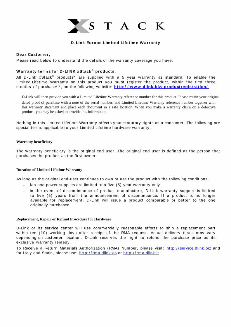
D-Link Europe Limited Lifetime Warranty
Dear Customer,
Please read below to understand the details of the warranty coverage you have. Warranty terms for D-LINK xStack® products:
All D-Link xStack® products* are supplied with a 5 year warranty as standard. To enable the Limited Lifetime Warranty on this product you must register the product, within the first three months of purchase**, on the following website: http://www.dlink.biz/productregistration/
D-Link will then provide you with a Limited Lifetime Warranty reference number for this product. Please retain your original dated proof of purchase with a note of the serial number, and Limited Lifetime Warranty reference number together with this warranty statement and place each document in a safe location. When you make a warranty claim on a defective product, you may be asked to provide this information.
Nothing in this Limited Lifetime Warranty affects your statutory rights as a consumer. The following are special terms applicable to your Limited Lifetime hardware warranty.
Warranty beneficiary
The warranty beneficiary is the original end user. The original end user is defined as the person that purchases the product as the first owner.
Duration of Limited Lifetime Warranty
As long as the original end-user continues to own or use the product with the following conditions: - fan and power supplies are limited to a five (5) year warranty only
- in the event of discontinuance of product manufacture, D-Link warranty support is limited to five (5) years from the announcement of discontinuance. If a product is no longer available for replacement, D-Link will issue a product comparable or better to the one originally purchased.
Replacement, Repair or Refund Procedure for Hardware
D-Link or its service center will use commercially reasonable efforts to ship a replacement part within ten (10) working days after receipt of the RMA request. Actual delivery times may vary depending on customer location. D-Link reserves the right to refund the purchase price as its exclusive warranty remedy.
To Receive a Return Materials Authorization (RMA) Number, please visit: http://service.dlink.biz and for Italy and Spain, please use: http://rma.dlink.es or http://rma.dlink.it.

D-Link Limited Lifetime Warranty
Hardware: D-Link warrants the D-Link hardware named above against defects in materials and workmanship for the period specified above. If D-Link receives notice of such defects during the warranty period, D-Link will, at its option, either repair or replace products proving to be defective. Replacement products may be either new or like-new.
Software. D-Link warrants that D-Link software will not fail to execute its programming instructions, for the period specified above, due to defects in material and workmanship when properly installed and used. If D-Link receives notice of such defects during the warranty period, D-Link will replace software media that does not execute its programming instructions due to such defects.
Warranty exclusions This warranty does not apply if the software, product or any other equipment upon which the software is authorized to be used (a) has been altered, except by D-Link or its authorized representative, (b) has not been installed, operated, repaired, or maintained in accordance with instructions supplied by D-Link (improper use or improper maintenance), (c) has been subjected to abnormal physical or electrical stress, misuse, negligence, or accident; (d) is licensed, for beta, evaluation, testing or demonstration purposes for which D-Link does not charge a purchase price or license fee or (e) defects are caused by force majeure (lightning, floods, war, etc.), soiling, by extraordinary environmental influences or by other circumstances of which D-Link is not responsible.
Disclaimer of warranty
Please note, some countries do not allow the disclaimer of implied terms in contracts with consumers and the disclaimer below may not apply to you.
To the extend allowed by local law, the above warranties are exclusive and no other warranty, condition or other term, whether written or oral, is expressed or implied. D-Link specifically disclaims any implied warranties, conditions and terms of merchantability, satisfactory quality, and fitness for a particular purpose.
To the extent allowed by local law, the remedies in this warranty statement are customer’s sole and exclusive remedies. Except as indicated above, in no event will D-Link or its suppliers be liable for loss of data or for indirect, special, incidental, consequential (including lost profit or data), or other damage, whether based in a contract, tort, or otherwise.
To the extent local law mandatorily requires a definition of “Lifetime Warranty” different from that provided here, then the local law definition will supersede and take precedence.
Valid law The warranty is subject to the valid laws in the country of purchase and is to be interpreted in the warranty terms with the said laws. You may have additional legal rights that are not restricted by this warranty. Nothing in this Limited Lifetime Warranty affects your statutory rights as a consumer.
* DES-6500 series is excluded from the Limited Lifetime Warranty offering and will be supplied with a standard 5 year warranty.
** Failure to register this product within the first three months of purchase [by the first user only] will invalidate the Limited Lifetime Warranty.

Tech Support
Technical Support You can find software updates and user documentation on the D-Link
website.
D-Link provides free technical support for customers within the United States and within Canada for the duration of the service period, and
warranty confirmation service, during the warranty period on this product. U.S. and Canadian customers can contact D-Link technical support through
our website, or by phone.
Tech Support for customers within the United States: D-Link Technical Support over the Telephone:
(877) 354-6555 Monday to Friday 8:00am to 5:00pm PST
D-Link Technical Support over the Internet: http://support.dlink.com
email:[email protected]
Tech Support for customers within Canada: D-Link Technical Support over the Telephone:
1-800-361-5265 Monday to Friday 7:30am to 9:00pm EST
D-Link Technical Support over the Internet: http://support.dlink.com email: [email protected]

Technical Support
D-Link UK Technical Support over the Telephone: 0871 873 3000 (United Kingdom)
BT 10ppm (UK Pence per minute), other carriers may vary. Times Mon-Fri 9.00am - 6.00pm Sat 10.00am - 2.00pm
+1890 886 899 (Ireland) €0.05ppm peak, €0.045ppm off peak Times Mon-Fri 9.00am -
6.00pm Sat 10.00am - 2.00pm D-Link UK & Ireland Technical Support over the Internet:
http://www.dlink.co.uk ftp://ftp.dlink.co.uk

Technische Unterstützung
Aktualisierte Versionen von Software und Benutzerhandbuch finden Sie auf der Website von D-Link.
D-Link bietet kostenfreie technische Unterstützung für Kunden
innerhalb Deutschlands, Österreichs, der Schweiz und Osteuropas.
Unsere Kunden können technische Unterstützung über unsere
Website, per E-Mail oder telefonisch anfordern.
Telefon: +49 (1805)2787 0,14€ pro Minute
Web: http://www.dlink.de E-Mail: [email protected]

Assistance technique
Vous trouverez la documentation et les logiciels les plus récents sur le site web D-Link.
Vous pouvez contacter le service technique de D-Link par notre site internet ou par téléphone.
Assistance technique D-Link par téléphone:
0 820 0803 03 0,12 €/min
Hours : Monday - Friday 9h to 13h and 14h to 19h Saturday 9h to 13h and from 14h to 16h
Assistance technique D-Link sur internet :
Web: http://www.dlink.fr E-mail: [email protected]

Asistencia Técnica
Puede encontrar las últimas versiones de software así como documentación técnica en el sitio web de D-Link.
D-Link ofrece asistencia técnica gratuita para clientes residentes
en España durante el periodo de garantía del producto.
Asistencia Técnica de D-Link por teléfono: +34 902 30 45 45
0,067 €/min Lunes a Viernes de 9:00 a 14:00 y de 15:00 a 18:00
Web: http://www.dlink.es E-mail: [email protected]

Supporto tecnico
Gli ultimi aggiornamenti e la documentazione sono disponibili sul sito D-Link.
Supporto Tecnico dal lunedì al venerdì dalle ore 9.00 alle ore
19.00 con orario continuato Telefono: 199400057
Web: http://www.dlink.it/support

Technical Support
You can find software updates and user documentation on the D-Link website.
D-Link provides free technical support for customers within
Benelux for the duration of the warranty period on this product.
Benelux customers can contact D-Link technical support through our website, or by phone.
Netherlands
0900 501 2007 €0.15ppm anytime Web: www.dlink.nl
Belgium
070 66 06 40 €0.175ppm peak, €0.0875ppm off peak
Web: www.dlink.be
Luxemburg +32 70 66 06 40
Web: www.dlink.be

Pomoc techniczna
Najnowsze wersje oprogramowania i dokumentacji użytkownika można znaleźć w serwisie internetowym firmy D-
Link.
D-Link zapewnia bezpłatną pomoc techniczną klientom w Polsce w okresie gwarancyjnym produktu.
Klienci z Polski mogą się kontaktować z działem pomocy technicznej firmy D-Link za pośrednictwem Internetu lub
telefonicznie.
Telefoniczna pomoc techniczna firmy D-Link: 0 801 022 021
Pomoc techniczna firmy D-Link świadczona przez Internet:
Web: http://www.dlink.pl E-mail: [email protected]

Technická podpora
Aktualizované verze software a uživatelských příruček najdete na webové stránce firmy D-Link.
D-Link poskytuje svým zákazníkům bezplatnou technickou
podporu
Zákazníci mohou kontaktovat oddělení technické podpory přes webové stránky, mailem nebo telefonicky
Telefon: 225 281 553
Land Line 1,78 CZK/min - Mobile 5.40 CZK/min Telefonická podpora je v provozu: PO- PÁ od 09.00 do 17.00
Web: http://www.dlink.cz/suppport/
E-mail: [email protected]

Technikai Támogatás
Meghajtó programokat és frissítéseket a D-Link Magyarország weblapjáról tölthet le.
Tel: 06 1 461-3001 Fax: 06 1 461-3004
Land Line 14,99 HUG/min - Mobile 49.99,HUF/min
Web: http://www.dlink.hu E-mail: [email protected]

Teknisk Support
Du kan finne programvare oppdateringer og bruker dokumentasjon på D-Links web sider.
D-Link tilbyr sine kunder gratis teknisk support under produktets garantitid.
Kunder kan kontakte D-Links teknisk support via våre hjemmesider, eller på tlf.
D-Link Teknisk telefon Support:
800 10 610 (Hverdager 08:00-20:00)
D-Link Teknisk Support over Internett:
Web: http://www.dlink.no

Teknisk Support
Du finder software opdateringer og bruger- dokumentation på D-Link’s hjemmeside.
D-Link tilbyder gratis teknisk support til kunder
i Danmark i hele produktets garantiperiode.
Danske kunder kan kontakte D-Link’s tekniske support via vores hjemmeside eller telefonisk.
D-Link teknisk support over telefonen:
Tlf. 7026 9040 Åbningstider: kl. 08:00 – 20:00
D-Link teknisk support på Internettet:
Web: http://www.dlink.dk

Teknistä tukea asiakkaille Suomessa
D-Link tarjoaa teknistä tukea asiakkailleen.
Tuotteen takuun voimassaoloajan. Tekninen tuki palvelee seuraavasti:
numerosta : 0800-114 677
Arkisin klo. 9 - 21
Internetin kautta: Web: http://www.dlink.fi

Teknisk Support
På vår hemsida kan du hitta mer information om mjukvaru uppdateringar och annan användarinformation.
D-Link tillhandahåller teknisk support till kunder i Sverige under hela garantitiden för denna produkt.
D-Link Teknisk Support via telefon:
0770-33 00 35 Vardagar 08.00-20.00
D-Link Teknisk Support via Internet:
Web: http://www.dlink.se

Suporte Técnico
Você pode encontrar atualizações de software e documentação de utilizador no site de D-Link Portugal
http://www.dlink.pt.
A D-Link fornece suporte técnico gratuito para clientes no Portugal durante o período de vigência de garantia deste
produto.
Assistência Técnica da D-Link na Internet: Web: http://www.dlink.pt E-mail: [email protected]

Τεχνική Υποστήριξη
Μπορείτε να βρείτε software updates και πληροφορίες για τη χρήση των προϊόντων στις ιστοσελίδες της D-Link
Η D-Link προσφέρει στους πελάτες της δωρεάν υποστήριξη
στον Ελλαδικό χώρο
Μπορείτε να επικοινωνείτε με το τμήμα τεχνικής υποστήριξης μέσω της ιστοσελίδας ή μέσω τηλεφώνου
D-Link Hellas Support Center Κεφαλληνίας 64, 11251 Αθήνα,
Τηλ: 210 86 11 114 (Δευτέρα- Παρασκευή 09:00-17:00) Φαξ: 210 8611114
Web: http://www.dlink.gr/support

Tehnička podrška
Hvala vam na odabiru D-Link proizvoda. Za dodatne informacije, podršku i upute za korištenje uređaja, molimo vas
da posjetite D-Link internetsku stranicu na www.dlink.eu
Web: www.dlink.biz/hr

Tehnična podpora
Zahvaljujemo se vam, ker ste izbrali D-Link proizvod. Za vse nadaljnje informacije, podporo ter navodila za uporabo prosimo
obiščite D-Link - ovo spletno stran www.dlink.eu
Web: www.dlink.biz/sl

Suport tehnica
Vă mulţumim pentru alegerea produselor D-Link. Pentru mai multe informaţii, suport şi manuale ale produselor vă rugăm să
vizitaţi site-ul D-Link www.dlink.eu
Web: www.dlink.ro

Technical Support You can find software updates and user documentation on the D-Link website.
Tech Support for customers in Australia:
Tel: 1300-766-868 Monday to Friday 8:00am to 8:00pm EST
Saturday 9:00am to 1:00pm EST http://www.dlink.com.au
e-mail: [email protected]
India: Tel: 1800-222-002
Monday to Friday 9:30AM to 7:00PM http://www.dlink.co.in/support/productsupport.aspx
Indonesia, Malaysia, Singapore and Thailand: Tel: +62-21-5731610 (Indonesia) Tel: 1800-882-880 (Malaysia) Tel: +65 66229355 (Singapore) Tel: +66-2-719-8978/9 (Thailand)
Monday to Friday 9:00am to 6:00pm http://www.dlink.com.sg/support/
e-mail: [email protected]
Korea: Tel: +82-2-890-5496
Monday to Friday 9:00am to 6:00pm http://www.d-link.co.kr e-mail: [email protected]
New Zealand: Tel: 0800-900-900
Monday to Friday 8:30am to 8:30pm Saturday 9:00am to 5:00pm
http://www.dlink.co.nz e-mail: [email protected]

Technical Support You can find software updates and user documentation on the D-Link website.
Tech Support for customers in Egypt:
Tel: +202-2919035 or +202-2919047 Sunday to Thursday 9:00am to 5:00pm
http://support.dlink-me.com e-mail: [email protected]
Iran: Tel: +98-21-88822613
Sunday to Thursday 9:00am to 6:00pm http://support.dlink-me.com
e-mail: [email protected]
Israel: Tel: +972-9-9715701
Sunday to Thursday 9:00am to 5:00pm http://www.dlink.co.il/support/
e-mail: [email protected]
Pakistan: Tel: +92-21-4548158 or +92-21-4548310 Sunday to Thursday 9:00am to 6:00pm
http://support.dlink-me.com e-mail: [email protected]
South Africa and Sub Sahara Region: Tel: +27-12-665-2165
08600 DLINK (for South Africa only) Monday to Friday 8:30am to 9:00pm South Africa Time
http://www.d-link.co.za
Turkey: Tel: +90-212-2895659
Monday to Friday 9:00am to 6:00pm http://www.dlink.com.tr
e-mail: [email protected] e-mail: [email protected]
U.A.E and North Africa: Tel: +971-4-391-6480 (U.A.E)
Sunday to Wednesday 9:00am to 6:00pm GMT+4 Thursday 9:00am to 1:00pm GMT+4
http://support.dlink-me.com e-mail: [email protected]

Техническая поддержка
Обновления программного обеспечения и документация доступны на Интернет-сайте D-Link.
D-Link предоставляет бесплатную поддержку для клиентов
в течение гарантийного срока.
Клиенты могут обратиться в группу технической поддержки D-Link по телефону или через Интернет.
Техническая поддержка D-Link:
+495-744-00-99
Техническая поддержка через Интернет http://www.dlink.ru
e-mail: [email protected]

Asistencia Técnica D-Link Latin América pone a disposición de sus clientes, especificaciones,
documentación y software mas reciente a través de nuestro Sitio Web www.dlinkla.com
El servicio de soporte técnico tiene presencia en numerosos países de la Región Latino América, y presta asistencia gratuita a todos los clientes de
D-Link, en forma telefónica e internet, a través de la casilla [email protected]
Soporte Técnico Help Desk Argentina: Teléfono: 0800-12235465 Lunes a Viernes 09:00 am a 22:00 pm Soporte Técnico Help Desk Chile: Teléfono: 800 8 35465 Lunes a Viernes 08:00 am a 21:00 pm Soporte Técnico Help Desk Colombia: Teléfono: 01800-9525465 Lunes a Viernes 07:00 am a 20:00 pm Soporte Técnico Help Desk Costa Rica: Teléfono: 0800 0521478 Lunes a Viernes 06:00 am a 19:00 pm Soporte Técnico Help Desk Ecuador: Teléfono: 1800-035465 Lunes a Viernes 07:00 am a 20:00 pm Soporte Técnico Help Desk El Salvador: Teléfono: 800-6335 Lunes a Viernes 06:00 am a 19:00 pm Soporte Técnico Help Desk Guatemala: Teléfono: 1800-8350255 Lunes a Viernes 06:00 am a 19:00 pm Soporte Técnico Help Desk México: Teléfono: 01800 1233201 Lunes a Viernes 06:00 am a 19:00 Soporte Técnico Help Desk Panamá: Teléfono: 011 008000 525465 Lunes a Viernes 07:00 am a 20:00 pm Soporte Técnico Help Desk Perú: Teléfono: 0800-00968 Lunes a Viernes 07:00 am a 20:00 pm Soporte Técnico Help Desk Venezuela: Teléfono: 0800-1005767 Lunes a Viernes 07:30 am a 20:30 pm

Suporte Técnico
Você pode encontrar atualizações de software e documentação de usuário no site da D-Link Brasil www.dlinkbrasil.com.br.
A D-Link fornece suporte técnico gratuito para clientes no Brasil
durante o período de vigência da garantia deste produto.
Suporte Técnico para clientes no Brasil:
Telefone São Paulo +11-2185-9301
Segunda à sexta Das 8h30 às 18h30
Demais Regiões do Brasil 0800 70 24 104
E-mail: e-mail: [email protected]

D-Link 友訊科技 台灣分公司 技術支援資訊
如果您還有任何本使用手冊無法協助您解決的產品相關問題,台灣 地區用戶可以透過我們的網站、電子郵件或電話等方式與D-Link台灣
地區技術支援工程師聯絡。
D-Link 免付費技術諮詢專線 0800-002-615
服務時間:週一至週五,早上8:30到晚上9:00 (不含周六、日及國定假日)
網 站:http://www.dlink.com.tw 電子郵件:[email protected]
如果您是台灣地區以外的用戶,請參考D-Link網站全球各地 分公司的聯絡資訊以取得相關支援服務。
產品保固期限、台灣區維修據點查詢,請參考以下網頁說明:
http://www.dlink.com.tw

Dukungan Teknis
Update perangkat lunak dan dokumentasi pengguna dapat diperoleh pada situs web D-Link.
Dukungan Teknis untuk pelanggan:
Dukungan Teknis D-Link melalui telepon:
Tel: +62-21-5731610
Dukungan Teknis D-Link melalui Internet: Email : [email protected]
Website : http://support.dlink.co.id

技术支持
您可以在 D-Link 的官方網站找到產品的軟件升級和使用手冊
办公地址:北京市东城区北三环东路 36号 环球贸易中心 B
座 26F 02-05室 邮编: 100013
技术支持中心电话:8008296688/ (028)66052968
技术支持中心传真:(028)85176948
维修中心地址:北京市东城区北三环东路 36号 环球贸易中心 B座 26F 02-05室 邮编: 100013
维修中心电话:(010) 58257789
维修中心传真:(010) 58257790
网址:http://www.dlink.com.cn
办公时间:周一到周五,早09:00到晚18:00

International Offices
U.S.A 17595 Mt. Herrmann Street Fountain Valley, CA 92708 TEL: 1-800-326-1688 URL: www.dlink.com Canada 2180 Winston Park Drive Oakville, Ontario, L6H 5W1 Canada TEL: 1-905-8295033 FAX: 1-905-8295223 URL: www.dlink.ca Europe (U. K.) D-Link (Europe) Ltd D-Link House, Abbey Road Park Royal, London NW10 7BX United Kingdom TEL: +44 (0)20 8955 9000 FAX: +44 (0)20 8955 9001 URL: www.dlink.co.uk Austria Millennium Tower Handelskai 94-96 A-1200 WIEN, Austria TEL: +43 (0)1 240 27 270 FAX: +43 (0)1 240 27 271 URL: www.dlink.at Belgium Rue des Colonies 11 B-1000 Brussels, Belgium TEL: +32 (0)2 517 7111 FAX: +32 (0)2 517 6500 URL: www.dlink.be Bulgaria 60A Bulgaria Blvd., Office 1, Sofia 1680, Bulgaria TEL: +359 2 958 22 42 FAX: +359 2 958 65 57 URL: www.dlink.eu Czech Republic Vaclavske namesti 36 110 00 Praha 1 Czech Republic TEL: +420 224 247 500 FAX: +420 224 234 967 Hot line CZ: +420 225 281 553 Hot line SK: +421 263 813 628 URL: www.dlink.cz URL: www.dlink.sk Denmark Naverland 2, DK-2600 Glostrup, Copenhagen, Denmark TEL: +45 43 96 9 040 FAX: +45 43 42 43 47 URL: www.dlink.dk Finland Latokartanontie 7A FIN-00700 Helsinki, Finland TEL : +358 10 309 8840 FAX: + 358 10 309 8841 URL: www.dlink.fi France 41 boulevard Vauban 78280 Guyancourt France TEL: +33 (0)1 30 23 86 88 FAX: +33 (0)1 30 23 86 89 URL: www.dlink.fr
Germany Schwalbacher Strasse 74 D-65760 Eschborn, Germany TEL: +49 (0)6196 77 99 0 FAX: +49 (0)6196 77 99 300 URL: www.dlink.de Greece 101, Panagoulis Str. 163-43 Heliopolis, Athens, Greece TEL: +30 210 9914512 FAX:+30 210 9916902 URL: www.dlink.gr Hungary Rákóczi út 70-72 HU-1074 Budapest, Hungary TEL: +36 (0) 1 461 30 00 FAX: +36 (0) 1 461 30 04 URL: www.dlink.hu Italy Via Nino Bonnet n. 6/b 20154 – Milano, Italy TEL: +39 02 2900 0676 FAX: +39 02 2900 1723 URL: www.dlink.it Luxembourg Rue des Colonies 11 B-1000 Brussels, Belgium TEL: +32 (0)2 517 7111 FAX: +32 (0)2 517 6500 URL: www.dlink.be Netherlands Weena 290 3012NJ Rotterdam, Netherlands TEL: +31 (0)10 282 1445 FAX: +31 (0)10 282 1331 URL: www.dlink.nl Norway Karihaugveien 89 N-1086 Oslo, Norway TEL: +47 99 300 100 FAX: +47 22 30 90 85 URL: www.dlink.no Poland Budynek Aurum ul. Waliców 11 00-851 Warszawa, Poland TEL: +48 (0) 22 583 92 75 FAX: +48 (0) 22 583 92 76 URL: www.dlink.pl Portugal Rua Fernando Palha, 50 Edificio Simol 1900 Lisbon, Portugal TEL: +351 21 8688493 FAX: +351 21 8622492 URL: www.dlink.es Romania B-dul Unirii nr. 55, bl. E4A, sc.2, et. 4, ap. 39, sector 3, Bucuresti, Romania TEL: +40(0)21 320 23 05 FAX: +40(0)21 320 23 07 URL: www.dlink.eu
Spain Avenida Diagonal, 593-95, 9th floor 08014 Barcelona, Spain TEL: +34 93 409 07 70 FAX: +34 93 491 07 95 URL: www.dlink.es Sweden Gustavslundsvägen 151B S-167 51 Bromma Sweden TEL: +46 (0)8 564 619 00 FAX: +46 (0)8 564 619 01 URL: www.dlink.se Switzeerland Glatt Tower, 2.OG Postfach CH-8301 Glattzentrum Switzerland TEL: +41 (0)1 832 11 00 FAX: +41 (0)1 832 11 01 URL: www.dlink.ch Singapore 1 International Business Park #03-12 The Synergy Singapore 609917 TEL: 65-6774-6233 FAX: 65-6774-6322 URL: www.dlink-intl.com Australia 1 Giffnock Avenue North Ryde, NSW 2113 Australia TEL: 61-2-8899-1800 FAX: 61-2-8899-1868 URL: www.dlink.com.au India D-Link House, Plot No.5, Kurla-Bandra Complex Road, Off. CST Road, Santacruz (E), Mumbai - 400 098 India TEL: 91-22-26526696/ 30616666 FAX: 91-22-26528914/ 8476 URL: www.dlink.co.in Middle East(Dubai) P.O.Box: 500376 Office: 103, Building:3 Dubai Internet City Dubai, United Arab Emirates TEL: +971-4-3916480 FAX: +971-4-3908881 URL: www.dlink-me.com Turkey Cayazaya Maslak Yolu S/A Kat: 5, Istanbul, Turkey TEL: 0212-289-5659 FAX:0212-289-7606 URL: www.dlink.com.tr Iran Unit 6, No. 39, 6th Alley, Sanaei St, Karimkhan Ave Tehran-IRAN TEL: 9821 8882 2613 FAX: 9821 8883 5492 Pakistan Office#311, Business Avenue Main Shahrah-e-Faisal Karachi-Pakistan TEL: 92-21-4548158, 4548310 FAX: 92-21-4535103
Egypt 47,El Merghany street, Heliopolis Cairo-Egypt TEL: +202-2919035, +202-2919047 FAX: +202-2919051 URL: www.dlink-me.com Israel 11 Hamanofim Street Ackerstein Towers, Regus Business Center P.O.B 2148, Hertzelia-Pituach 46120 Israel TEL: +972-9-9715700 FAX: +972-9-9715601 URL: www.dlink.co.il Latin America Av. Vitacura # 2939, floor 6th Las Condes, Santiago RM Chile TEL: 56-2-5838-950 FAX: 56-2-5838-952 URL: www.dlinkla.com Brazil Av das Nacoes Unidas 11857 – 14- andar - cj 141/142 Brooklin Novo Sao Paulo - SP - Brazil CEP 04578-000 (Zip Code) TEL: (55 11) 21859300 FAX: (55 11) 21859322 URL: www.dlinkbrasil.com.br South Africa Einstein Park II Block B 102-106 Witch-Hazel Avenue First Floor Block B Einstein Park II Highveld Techno Park Centurion Gauteng Republic of South Africa TEL: 27-12-665-2165 FAX: 27-12-665-2186 URL: www.d-link.co.za Russia Grafsky per., 14, floor 6 Moscow 129626 Russia TEL: 7-495-744-0099 FAX: 7-495-744-0099 #350 URL: www.dlink.ru Japan K.K. Level 6 Konan YK Building, Konan 2-4-12 Minato-Ku Tokyo 108-0075, Japan URL: www.dlink-jp.com China No.202, C1 Building, Huitong Office Park, No. 71, Jianguo Road, Chaoyang District, Beijing 100025, China TEL +86-10-58635800 FAX: +86-10-58635799 URL: www.dlink.com.cn Taiwan No. 289, Sinhu 3rd Rd., Neihu District, Taipei City 114,Taiwan TEL: 886-2-6600-0123 FAX: 886-2-6600-1188 URL: www.dlink.com.tw

Registration Card All Countries and Regions Excluding USA
Print, type or use block letters.
Your name: Mr./Ms _____________________________________________________________________________
Organization: ________________________________________________ Dept. ____________________________
Your title at organization: ________________________________________________________________________
Telephone: _______________________________________ Fax:________________________________________
Organization's full address: ______________________________________________________________________
____________________________________________________________________________________________
Country: _____________________________________________________________________________________
Date of purchase (Month/Day/Year): _______________________________________________________________
Product Model Product Serial No. * Product installed in type of
computer
* Product installed in
computer serial No.
(* Applies to adapters only)
Product was purchased from:
Reseller's name: ______________________________________________________________________________
Telephone: _______________________________________
Answers to the following questions help us to support your product:
1. Where and how will the product primarily be used?
Home Office Travel Company Business Home Business Personal Use
2. How many employees work at installation site?
1 employee 2-9 10-49 50-99 100-499 500-999 1000 or more
3. What network protocol(s) does your organization use ?
XNS/IPX TCP/IP DECnet Others_____________________________
4. What network operating system(s) does your organization use ?
D-Link LANsmart Novell NetWare NetWare Lite SCO Unix/Xenix PC NFS 3Com 3+Open Cisco Network
Banyan Vines DECnet Pathwork Windows NT Windows 98 Windows 2000/ME Windows XP
Others__________________________________________
5. What network management program does your organization use ?
D-View HP OpenView/Windows HP OpenView/Unix SunNet Manager Novell NMS
NetView 6000 Others________________________________________
6. What network medium/media does your organization use ?
Fiber-optics Thick coax Ethernet Thin coax Ethernet 10BASE-T UTP/STP
100BASE-TX 1000BASE-T Wireless 802.11b and 802.11g wireless 802.11a Others_________________
7. What applications are used on your network?
Desktop publishing Spreadsheet Word processing CAD/CAM
Database management Accounting Others_____________________
8. What category best describes your company?
Aerospace Engineering Education Finance Hospital Legal Insurance/Real Estate Manufacturing
Retail/Chain store/Wholesale Government Transportation/Utilities/Communication VAR
System house/company Other________________________________
9. Would you recommend your D-Link product to a friend?
Yes No Don't know yet
10.Your comments on this product?
__________________________________________________________________________________________