Embed Size (px)
Citation preview
1
MAD315-MINING I LAB.
UNDERGROUND MINING RELATED PROBLEMS
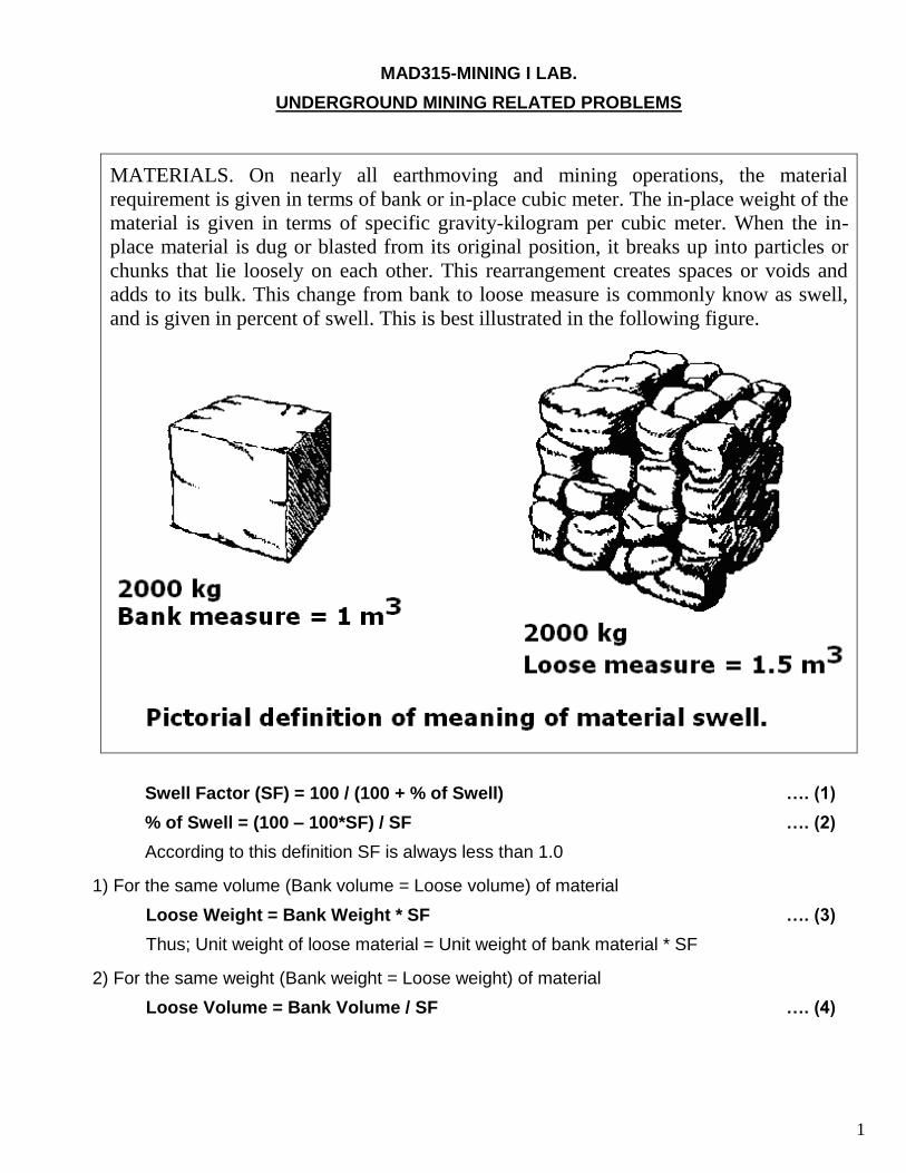
MATERIALS. On nearly all earthmoving and mining operations, the material
requirement is given in terms of bank or in-place cubic meter. The in-place weight of the
material is given in terms of specific gravity-kilogram per cubic meter. When the in-
place material is dug or blasted from its original position, it breaks up into particles or
chunks that lie loosely on each other. This rearrangement creates spaces or voids and
adds to its bulk. This change from bank to loose measure is commonly know as swell,
and is given in percent of swell. This is best illustrated in the following figure.
Swell Factor (SF) = 100 / (100 + % of Swell) …. (1)
% of Swell = (100 – 100*SF) / SF …. (2)
According to this definition SF is always less than 1.0
1) For the same volume (Bank volume = Loose volume) of material
Loose Weight = Bank Weight * SF …. (3)
Thus; Unit weight of loose material = Unit weight of bank material * SF
2) For the same weight (Bank weight = Loose weight) of material
Loose Volume = Bank Volume / SF …. (4)
2
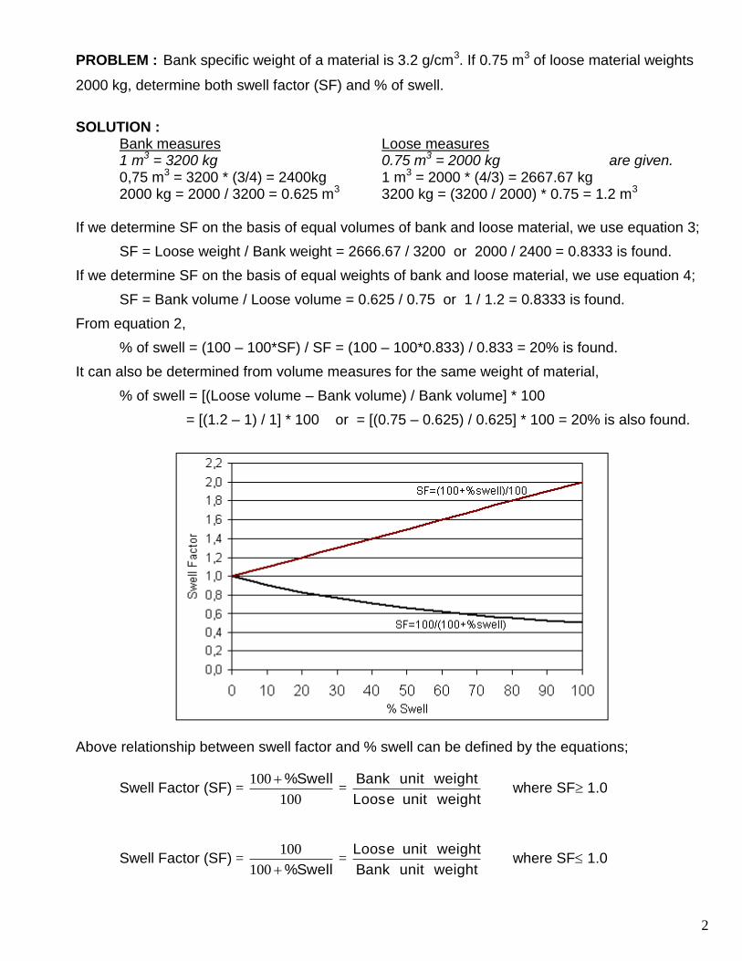
PROBLEM : Bank specific weight of a material is 3.2 g/cm3. If 0.75 m3 of loose material weights
2000 kg, determine both swell factor (SF) and % of swell.
SOLUTION : Bank measures Loose measures 1 m3 = 3200 kg 0.75 m3 = 2000 kg are given. 0,75 m3 = 3200 * (3/4) = 2400kg 1 m3 = 2000 * (4/3) = 2667.67 kg 2000 kg = 2000 / 3200 = 0.625 m3 3200 kg = (3200 / 2000) * 0.75 = 1.2 m3 If we determine SF on the basis of equal volumes of bank and loose material, we use equation 3;
SF = Loose weight / Bank weight = 2666.67 / 3200 or 2000 / 2400 = 0.8333 is found.
If we determine SF on the basis of equal weights of bank and loose material, we use equation 4;
SF = Bank volume / Loose volume = 0.625 / 0.75 or 1 / 1.2 = 0.8333 is found.
From equation 2,
% of swell = (100 – 100*SF) / SF = (100 – 100*0.833) / 0.833 = 20% is found.
It can also be determined from volume measures for the same weight of material,
% of swell = [(Loose volume – Bank volume) / Bank volume] * 100
= [(1.2 – 1) / 1] * 100 or = [(0.75 – 0.625) / 0.625] * 100 = 20% is also found.
Above relationship between swell factor and % swell can be defined by the equations;
Swell Factor (SF) = 100
100 Swell% =
weightunitLoose
weightunitBank where SF 1.0
Swell Factor (SF) = Swell%100
100 =
weightunitBank
weightunitLoose where SF 1.0
3
4
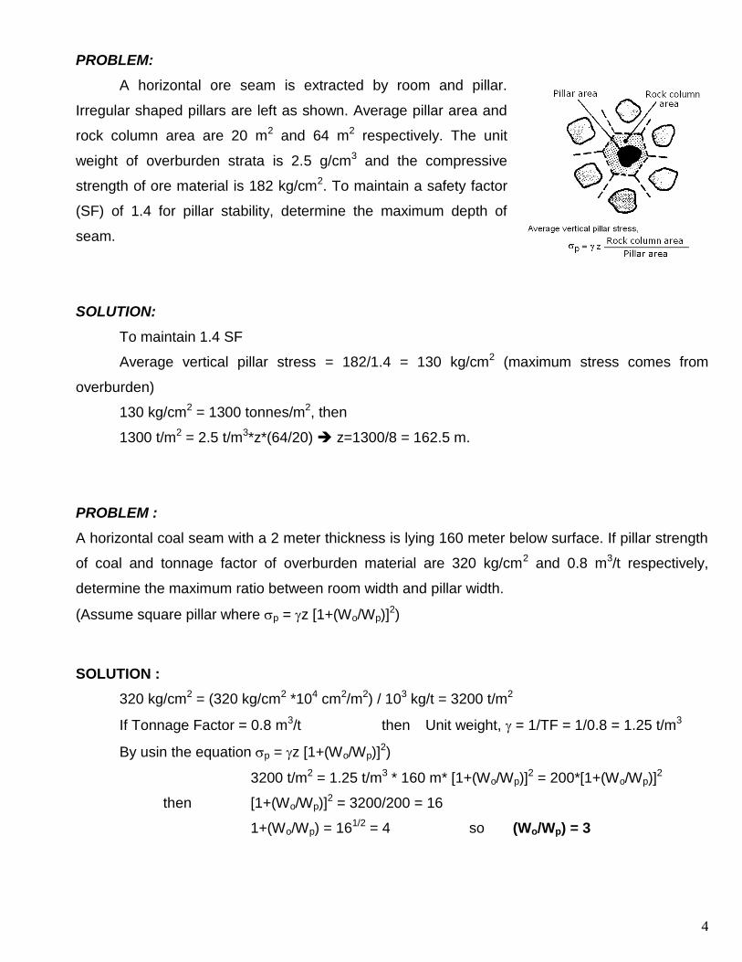
PROBLEM:
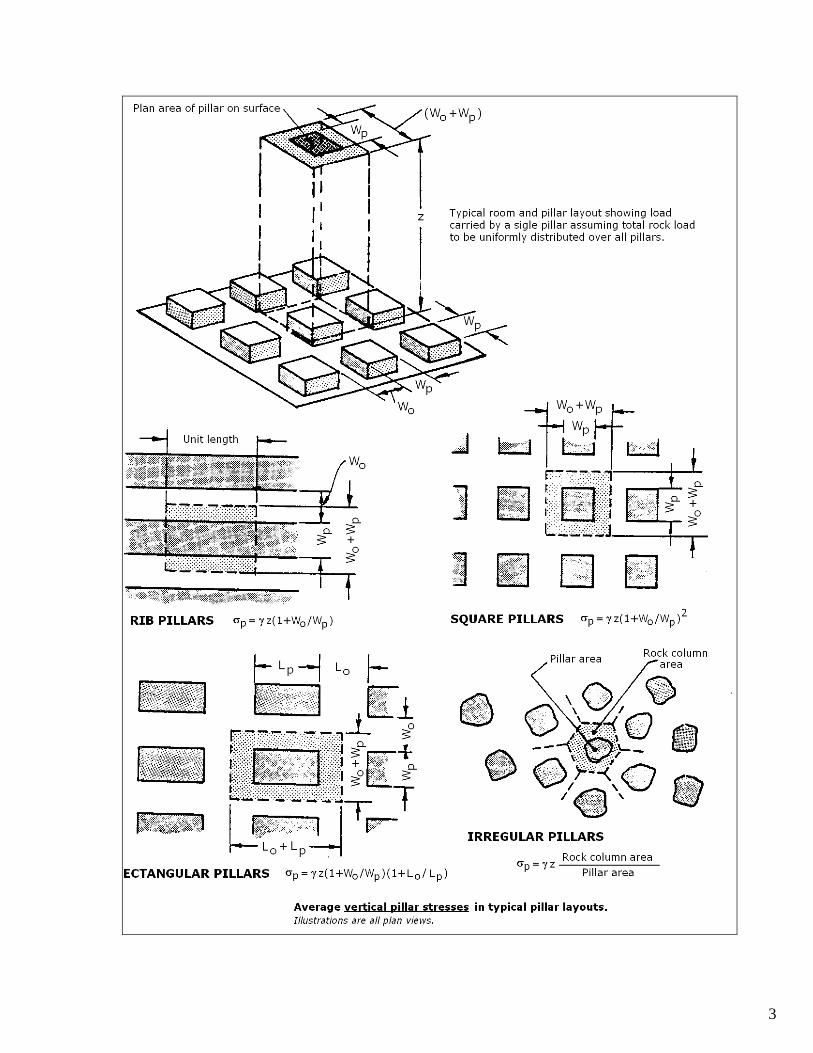
A horizontal ore seam is extracted by room and pillar.
Irregular shaped pillars are left as shown. Average pillar area and
rock column area are 20 m2 and 64 m2 respectively. The unit
weight of overburden strata is 2.5 g/cm3 and the compressive
strength of ore material is 182 kg/cm2. To maintain a safety factor
(SF) of 1.4 for pillar stability, determine the maximum depth of
seam.
SOLUTION:
To maintain 1.4 SF
Average vertical pillar stress = 182/1.4 = 130 kg/cm2 (maximum stress comes from
overburden)
130 kg/cm2 = 1300 tonnes/m2, then
1300 t/m2 = 2.5 t/m3*z*(64/20) z=1300/8 = 162.5 m.
PROBLEM :
A horizontal coal seam with a 2 meter thickness is lying 160 meter below surface. If pillar strength
of coal and tonnage factor of overburden material are 320 kg/cm2 and 0.8 m3/t respectively,
determine the maximum ratio between room width and pillar width.
(Assume square pillar where p = z [1+(Wo/Wp)]2)
SOLUTION :
320 kg/cm2 = (320 kg/cm2 *104 cm2/m2) / 103 kg/t = 3200 t/m2
If Tonnage Factor = 0.8 m3/t then Unit weight, = 1/TF = 1/0.8 = 1.25 t/m3
By usin the equation p = z [1+(Wo/Wp)]2)
3200 t/m2 = 1.25 t/m3 * 160 m* [1+(Wo/Wp)]2 = 200*[1+(Wo/Wp)]
2
then [1+(Wo/Wp)]2 = 3200/200 = 16
1+(Wo/Wp) = 161/2 = 4 so (Wo/Wp) = 3
5
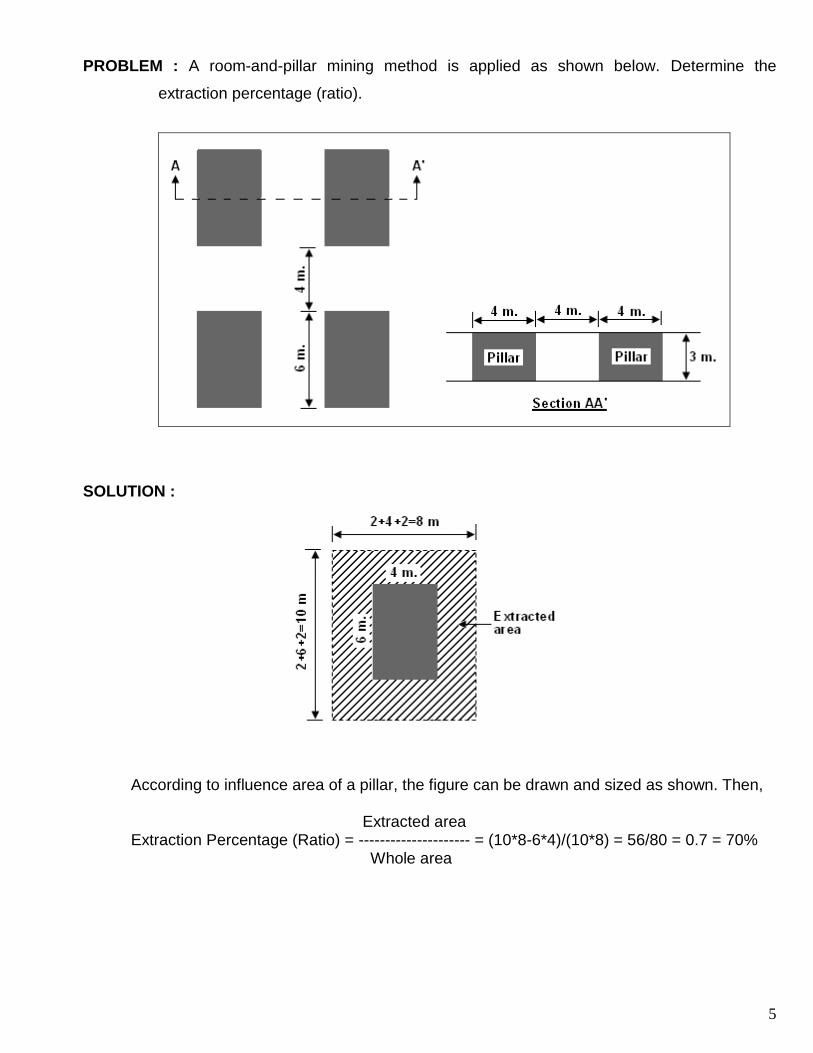
PROBLEM : A room-and-pillar mining method is applied as shown below. Determine the
extraction percentage (ratio).
SOLUTION :
According to influence area of a pillar, the figure can be drawn and sized as shown. Then, Extracted area Extraction Percentage (Ratio) = --------------------- = (10*8-6*4)/(10*8) = 56/80 = 0.7 = 70% Whole area
6
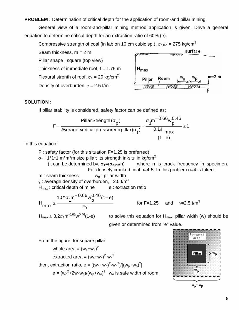
PROBLEM : Determination of critical depth for the application of room-and pillar mining
General view of a room-and-pillar mining method application is given. Drive a general
equation to determine critical depth for an extraction ratio of 60% (e).
Compressive strength of coal (in lab on 10 cm cubic sp.), c,lab = 275 kg/cm2
Seam thickness, m = 2 m
Pillar shape : square (top view)
Thickness of immediate roof, t = 1.75 m
Flexural strenth of roof, e = 20 kg/cm2
Density of overburden, = 2.5 t/m3
SOLUTION :
If pillar stability is considered, safety factor can be defined as;
1
e)(1
maxH0.1
0.46p
w0.66m1σ
)t
(σ pillar on pressure vertical Average
)p
(σ Strength Pillar
F
In this equation;
F : safety factor (for this situation F=1.25 is preferred)
1 : 1*1*1 m*m*m size pillar; its strength in-situ in kg/cm2
(it can be determined by, 1=(c,lab/n) where n is crack frequency in specimen.
For densely cracked coal n=4-5. In this problem n=4 is taken.
m : seam thickness wp : pillar width
: average density of overburden, =2.5 t/m3
Hmax : critical depth of mine e : extraction ratio
Fγ
e)(10.46p
w0.66m1σ*10
maxH
for F=1.25 and =2.5 t/m3
Hmax 3,21m-0.66w0.46(1-e) to solve this equation for Hmax, pillar width (w) should be
given or determined from "e" value.
From the figure, for square pillar
whole area = (wp+wo)2
extracted area = (wo+wp)2-wp
2
then, extraction ratio, e = [(wo+wp)2-wp
2]/[(wp+wo)2]
e = (wo2+2wowp)/(wp+wo)
2 wo is safe width of room
7
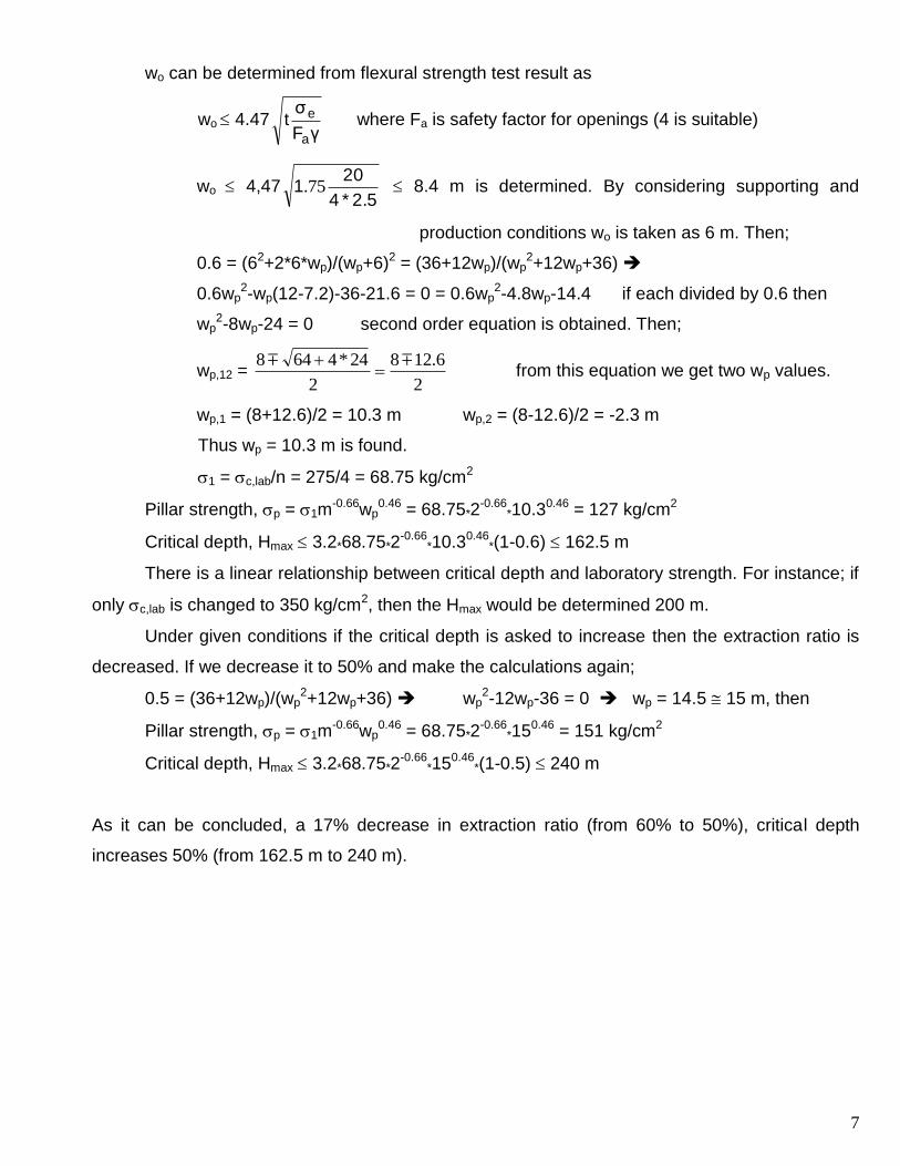
wo can be determined from flexural strength test result as
wo 4.47γF
σt
a
e where Fa is safety factor for openings (4 is suitable)
wo 4,472.5*4
201 75. 8.4 m is determined. By considering supporting and
production conditions wo is taken as 6 m. Then;
0.6 = (62+2*6*wp)/(wp+6)2 = (36+12wp)/(wp2+12wp+36)
0.6wp2-wp(12-7.2)-36-21.6 = 0 = 0.6wp
2-4.8wp-14.4 if each divided by 0.6 then
wp2-8wp-24 = 0 second order equation is obtained. Then;
wp,12 = 2
6.128
2
24*4648
from this equation we get two wp values.
wp,1 = (8+12.6)/2 = 10.3 m wp,2 = (8-12.6)/2 = -2.3 m
Thus wp = 10.3 m is found.
1 = c,lab/n = 275/4 = 68.75 kg/cm2
Pillar strength, p = 1m-0.66wp
0.46 = 68.75*2-0.66
*10.30.46 = 127 kg/cm2
Critical depth, Hmax 3.2*68.75*2-0.66
*10.30.46*(1-0.6) 162.5 m
There is a linear relationship between critical depth and laboratory strength. For instance; if
only c,lab is changed to 350 kg/cm2, then the Hmax would be determined 200 m.
Under given conditions if the critical depth is asked to increase then the extraction ratio is
decreased. If we decrease it to 50% and make the calculations again;
0.5 = (36+12wp)/(wp2+12wp+36) wp
2-12wp-36 = 0 wp = 14.5 15 m, then
Pillar strength, p = 1m-0.66wp
0.46 = 68.75*2-0.66
*150.46 = 151 kg/cm2
Critical depth, Hmax 3.2*68.75*2-0.66
*150.46*(1-0.5) 240 m
As it can be concluded, a 17% decrease in extraction ratio (from 60% to 50%), critical depth
increases 50% (from 162.5 m to 240 m).
8
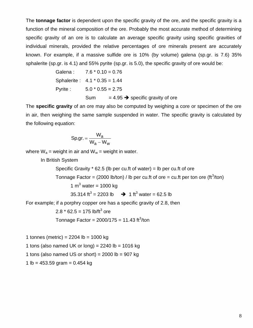
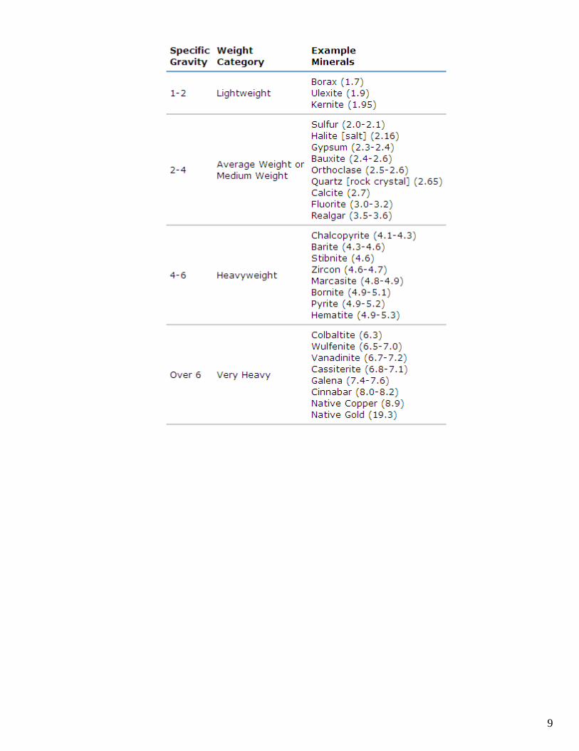
The tonnage factor is dependent upon the specific gravity of the ore, and the specific gravity is a
function of the mineral composition of the ore. Probably the most accurate method of determining
specific gravity of an ore is to calculate an average specific gravity using specific gravities of
individual minerals, provided the relative percentages of ore minerals present are accurately
known. For example, if a massive sulfide ore is 10% (by volume) galena (sp.gr. is 7.6) 35%
sphalerite (sp.gr. is 4.1) and 55% pyrite (sp.gr. is 5.0), the specific gravity of ore would be:
Galena : 7.6 * 0.10 = 0.76
Sphalerite : 4.1 * 0.35 = 1.44
Pyrite : 5.0 * 0.55 = 2.75
Sum = 4.95 specific gravity of ore
The specific gravity of an ore may also be computed by weighing a core or specimen of the ore
in air, then weighing the same sample suspended in water. The specific gravity is calculated by
the following equation:
wa
a
WW
W.gr.Sp
where Wa = weight in air and Ww = weight in water.
In British System
Specific Gravity * 62.5 (lb per cu.ft of water) = lb per cu.ft of ore
Tonnage Factor = (2000 lb/ton) / lb per cu.ft of ore = cu.ft per ton ore (ft3/ton)
1 m3 water = 1000 kg
35.314 ft3 = 2203 lb 1 ft3 water = 62.5 lb
For example; if a porphry copper ore has a specific gravity of 2.8, then
2.8 * 62.5 = 175 lb/ft3 ore
Tonnage Factor = 2000/175 = 11.43 ft3/ton
1 tonnes (metric) = 2204 lb = 1000 kg
1 tons (also named UK or long) = 2240 lb = 1016 kg
1 tons (also named US or short) = 2000 lb = 907 kg
1 lb = 453.59 gram = 0.454 kg
9
10
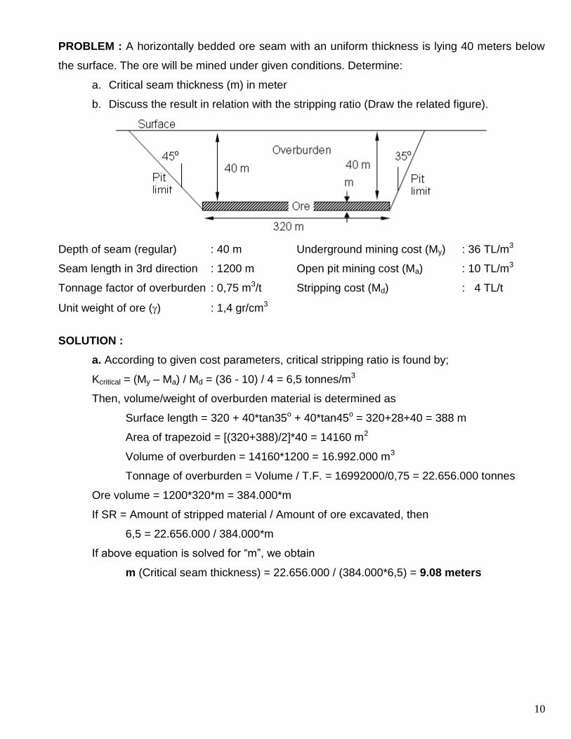
PROBLEM : A horizontally bedded ore seam with an uniform thickness is lying 40 meters below
the surface. The ore will be mined under given conditions. Determine:
a. Critical seam thickness (m) in meter
b. Discuss the result in relation with the stripping ratio (Draw the related figure).
Depth of seam (regular) : 40 m Underground mining cost (My) : 36 TL/m3
Seam length in 3rd direction : 1200 m Open pit mining cost (Ma) : 10 TL/m3
Tonnage factor of overburden : 0,75 m3/t Stripping cost (Md) : 4 TL/t
Unit weight of ore () : 1,4 gr/cm3
SOLUTION :
a. According to given cost parameters, critical stripping ratio is found by;
Kcritical = (My – Ma) / Md = (36 - 10) / 4 = 6,5 tonnes/m3
Then, volume/weight of overburden material is determined as
Surface length = 320 + 40*tan35o + 40*tan45o = 320+28+40 = 388 m
Area of trapezoid = [(320+388)/2]*40 = 14160 m2
Volume of overburden = 14160*1200 = 16.992.000 m3
Tonnage of overburden = Volume / T.F. = 16992000/0,75 = 22.656.000 tonnes
Ore volume = 1200*320*m = 384.000*m
If SR = Amount of stripped material / Amount of ore excavated, then
6,5 = 22.656.000 / 384.000*m
If above equation is solved for “m”, we obtain
m (Critical seam thickness) = 22.656.000 / (384.000*6,5) = 9.08 meters
11
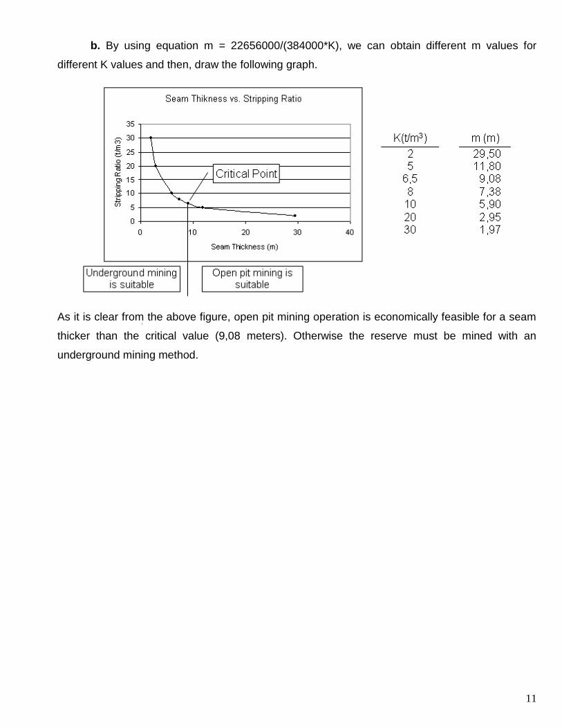
b. By using equation m = 22656000/(384000*K), we can obtain different m values for
different K values and then, draw the following graph.
As it is clear from the above figure, open pit mining operation is economically feasible for a seam
thicker than the critical value (9,08 meters). Otherwise the reserve must be mined with an
underground mining method.
12
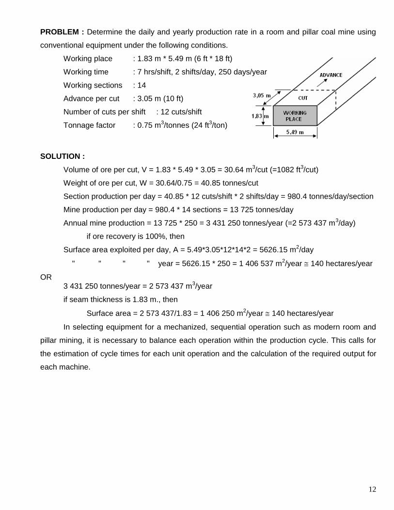
PROBLEM : Determine the daily and yearly production rate in a room and pillar coal mine using
conventional equipment under the following conditions.
Working place : 1.83 m * 5.49 m (6 ft * 18 ft)
Working time : 7 hrs/shift, 2 shifts/day, 250 days/year
Working sections : 14
Advance per cut : 3.05 m (10 ft)
Number of cuts per shift : 12 cuts/shift
Tonnage factor : 0.75 m3/tonnes (24 ft3/ton)
SOLUTION :
Volume of ore per cut, V = 1.83 * 5.49 * 3.05 = 30.64 m3/cut (=1082 ft3/cut)
Weight of ore per cut, W = 30.64/0.75 = 40.85 tonnes/cut
Section production per day = 40.85 * 12 cuts/shift * 2 shifts/day = 980.4 tonnes/day/section
Mine production per day = 980.4 * 14 sections = 13 725 tonnes/day
Annual mine production = 13 725 * 250 = 3 431 250 tonnes/year (=2 573 437 m3/day)
if ore recovery is 100%, then
Surface area exploited per day, A = 5.49*3.05*12*14*2 = 5626.15 m2/day
" " " " year = 5626.15 * 250 = 1 406 537 m2/year 140 hectares/year
OR 3 431 250 tonnes/year = 2 573 437 m3/year
if seam thickness is 1.83 m., then
Surface area = 2 573 437/1.83 = 1 406 250 m2/year 140 hectares/year
In selecting equipment for a mechanized, sequential operation such as modern room and
pillar mining, it is necessary to balance each operation within the production cycle. This calls for
the estimation of cycle times for each unit operation and the calculation of the required output for
each machine.
13
PROBLEM : Determine the cycle time per working place and the output rating of a gathering-arm
loader for a section of the coal mine in the previous problem, given the following additional
information.
Place change time : 3.5 min
Car change time : 0.6 min
Delay time/Place : 2.2 min
Shuttle car capacity : 7.3 tonnes (8 tons)
SOLUTION :
Allowable cycle time/working place = (7 hr/sh*60 min/hr) / 12 cuts/sh = 35 mins/cut
Net available loading time = 35 – (3.5+2.2) = 29.3 mins/cut
Number of shuttle car loads/cut = (40.85 tonnes/cut) / 7.3 tonnes/car = 5.6 cars = 6 cars
Loading time/Place = 29.3 – (6*0.6) = 25.7 mins
Required loader output = (40.85 tonnes/cut) / (25.7 mins/cut) = 1.59 tonnes/min
Since this is a minimum rating based on average performance, a loader with a
somewhat higher output, say, 3 or 4 tonnes/min would be selected to allow for surges and
contingencies.
14
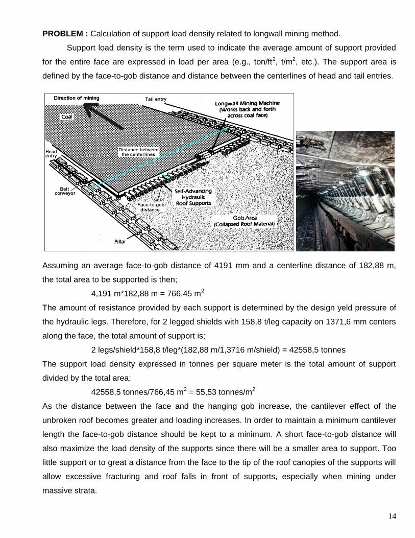
PROBLEM : Calculation of support load density related to longwall mining method.
Support load density is the term used to indicate the average amount of support provided
for the entire face are expressed in load per area (e.g., ton/ft2, t/m2, etc.). The support area is
defined by the face-to-gob distance and distance between the centerlines of head and tail entries.
Assuming an average face-to-gob distance of 4191 mm and a centerline distance of 182,88 m,
the total area to be supported is then;
4,191 m*182,88 m = 766,45 m2
The amount of resistance provided by each support is determined by the design yeld pressure of
the hydraulic legs. Therefore, for 2 legged shields with 158,8 t/leg capacity on 1371,6 mm centers
along the face, the total amount of support is;
2 legs/shield*158,8 t/leg*(182,88 m/1,3716 m/shield) = 42558,5 tonnes
The support load density expressed in tonnes per square meter is the total amount of support
divided by the total area;
42558,5 tonnes/766,45 m2 = 55,53 tonnes/m2
As the distance between the face and the hanging gob increase, the cantilever effect of the
unbroken roof becomes greater and loading increases. In order to maintain a minimum cantilever
length the face-to-gob distance should be kept to a minimum. A short face-to-gob distance will
also maximize the load density of the supports since there will be a smaller area to support. Too
little support or to great a distance from the face to the tip of the roof canopies of the supports will
allow excessive fracturing and roof falls in front of supports, especially when mining under
massive strata.
15
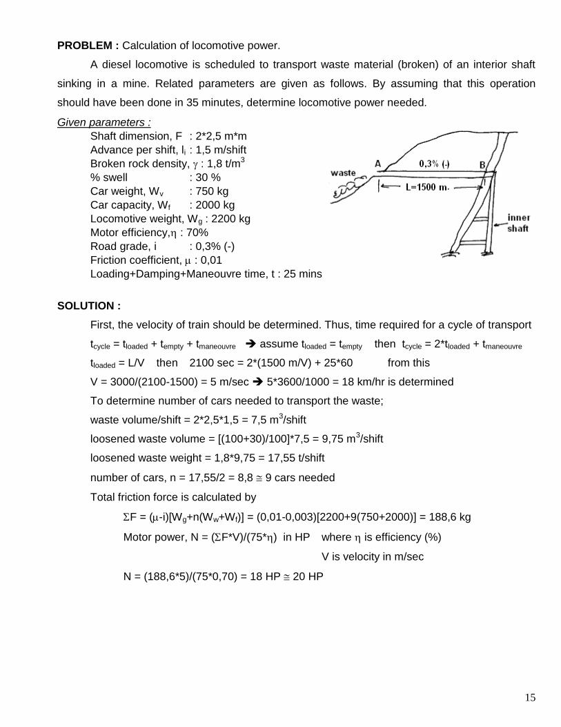
PROBLEM : Calculation of locomotive power.
A diesel locomotive is scheduled to transport waste material (broken) of an interior shaft
sinking in a mine. Related parameters are given as follows. By assuming that this operation
should have been done in 35 minutes, determine locomotive power needed.
Given parameters :
Shaft dimension, F : 2*2,5 m*m
Advance per shift, li : 1,5 m/shift
Broken rock density, : 1,8 t/m3
% swell : 30 %
Car weight, Wv : 750 kg
Car capacity, Wf : 2000 kg
Locomotive weight, Wg : 2200 kg
Motor efficiency, : 70%
Road grade, i : 0,3% (-)
Friction coefficient, : 0,01
Loading+Damping+Maneouvre time, t : 25 mins
SOLUTION :
First, the velocity of train should be determined. Thus, time required for a cycle of transport
tcycle = tloaded + tempty + tmaneouvre assume tloaded = tempty then tcycle = 2*tloaded + tmaneouvre
tloaded = L/V then 2100 sec = 2*(1500 m/V) + 25*60 from this
V = 3000/(2100-1500) = 5 m/sec 5*3600/1000 = 18 km/hr is determined
To determine number of cars needed to transport the waste;
waste volume/shift = 2*2,5*1,5 = 7,5 m3/shift
loosened waste volume = [(100+30)/100]*7,5 = 9,75 m3/shift
loosened waste weight = 1,8*9,75 = 17,55 t/shift
number of cars, n = 17,55/2 = 8,8 9 cars needed
Total friction force is calculated by
F = (-i)[Wg+n(Ww+Wf)] = (0,01-0,003)[2200+9(750+2000)] = 188,6 kg
Motor power, N = (F*V)/(75*) in HP where is efficiency (%)
V is velocity in m/sec
N = (188,6*5)/(75*0,70) = 18 HP 20 HP
16
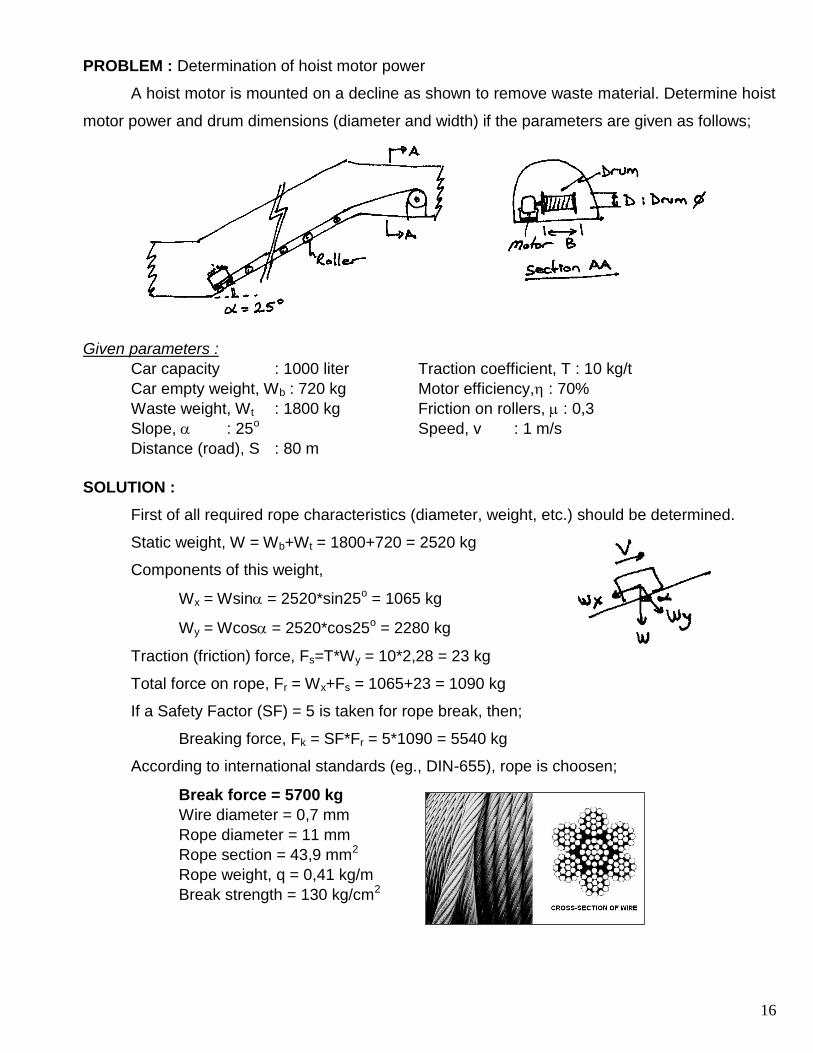
PROBLEM : Determination of hoist motor power
A hoist motor is mounted on a decline as shown to remove waste material. Determine hoist
motor power and drum dimensions (diameter and width) if the parameters are given as follows;
Given parameters :
Car capacity : 1000 liter Traction coefficient, T : 10 kg/t
Car empty weight, Wb : 720 kg Motor efficiency, : 70%
Waste weight, Wt : 1800 kg Friction on rollers, : 0,3
Slope, : 25o Speed, v : 1 m/s
Distance (road), S : 80 m
SOLUTION :
First of all required rope characteristics (diameter, weight, etc.) should be determined.
Static weight, W = Wb+Wt = 1800+720 = 2520 kg
Components of this weight,
Wx = Wsin = 2520*sin25o = 1065 kg
Wy = Wcos = 2520*cos25o = 2280 kg
Traction (friction) force, Fs=T*Wy = 10*2,28 = 23 kg
Total force on rope, Fr = Wx+Fs = 1065+23 = 1090 kg
If a Safety Factor (SF) = 5 is taken for rope break, then;
Breaking force, Fk = SF*Fr = 5*1090 = 5540 kg
According to international standards (eg., DIN-655), rope is choosen;
Break force = 5700 kg
Wire diameter = 0,7 mm
Rope diameter = 11 mm
Rope section = 43,9 mm2
Rope weight, q = 0,41 kg/m
Break strength = 130 kg/cm2
17
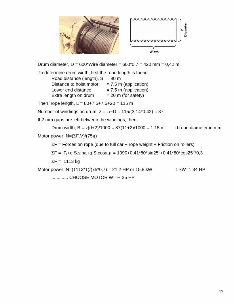
Drum diameter, D = 600*Wire diameter = 600*0,7 = 420 mm = 0,42 m
To determine drum width, first the rope length is found
Road distance (length), S = 80 m
Distance to hoist motor = 7,5 m (application)
Lower end distance = 7,5 m (application)
Extra length on drum = 20 m (for safety)
Then, rope length, L = 80+7,5+7,5+20 = 115 m
Number of windings on drum, z = L/D = 115/(3,14*0,42) = 87
If 2 mm gaps are left between the windings, then;
Drum width, B = z(d+2)/1000 = 87(11+2)/1000 = 1,15 m d:rope diameter in mm
Motor power, N=(F.V)/(75)
F = Forces on rope (due to full car + rope weight + Friction on rollers)
F = Fr+q.S.sin+q.S.cos. = 1090+0,41*80*sin25o+0,41*80*cos25o*0,3
F = 1113 kg
Motor power, N=(1113*1)/(75*0,7) = 21,2 HP or 15,8 kW 1 kW=1,34 HP
............. CHOOSE MOTOR WITH 25 HP
18
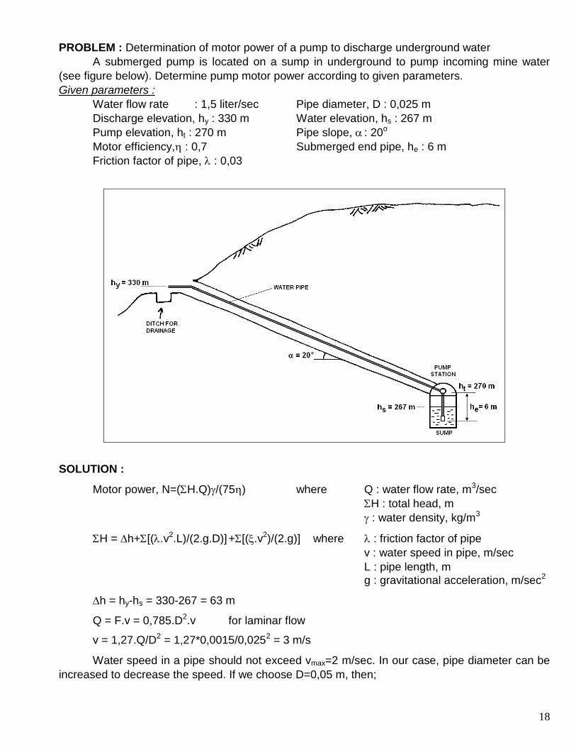
PROBLEM : Determination of motor power of a pump to discharge underground water
A submerged pump is located on a sump in underground to pump incoming mine water
(see figure below). Determine pump motor power according to given parameters.
Given parameters :
Water flow rate : 1,5 liter/sec Pipe diameter, D : 0,025 m
Discharge elevation, hy : 330 m Water elevation, hs : 267 m
Pump elevation, ht : 270 m Pipe slope, : 20o
Motor efficiency, : 0,7 Submerged end pipe, he : 6 m
Friction factor of pipe, : 0,03
SOLUTION :
Motor power, N=(H.Q)/(75) where Q : water flow rate, m3/sec
H : total head, m
: water density, kg/m3
H = h+[(.v2.L)/(2.g.D)] +[(.v2)/(2.g)] where : friction factor of pipe
v : water speed in pipe, m/sec
L : pipe length, m
g : gravitational acceleration, m/sec2
h = hy-hs = 330-267 = 63 m
Q = F.v = 0,785.D2.v for laminar flow
v = 1,27.Q/D2 = 1,27*0,0015/0,0252 = 3 m/s
Water speed in a pipe should not exceed vmax=2 m/sec. In our case, pipe diameter can be
increased to decrease the speed. If we choose D=0,05 m, then;
19
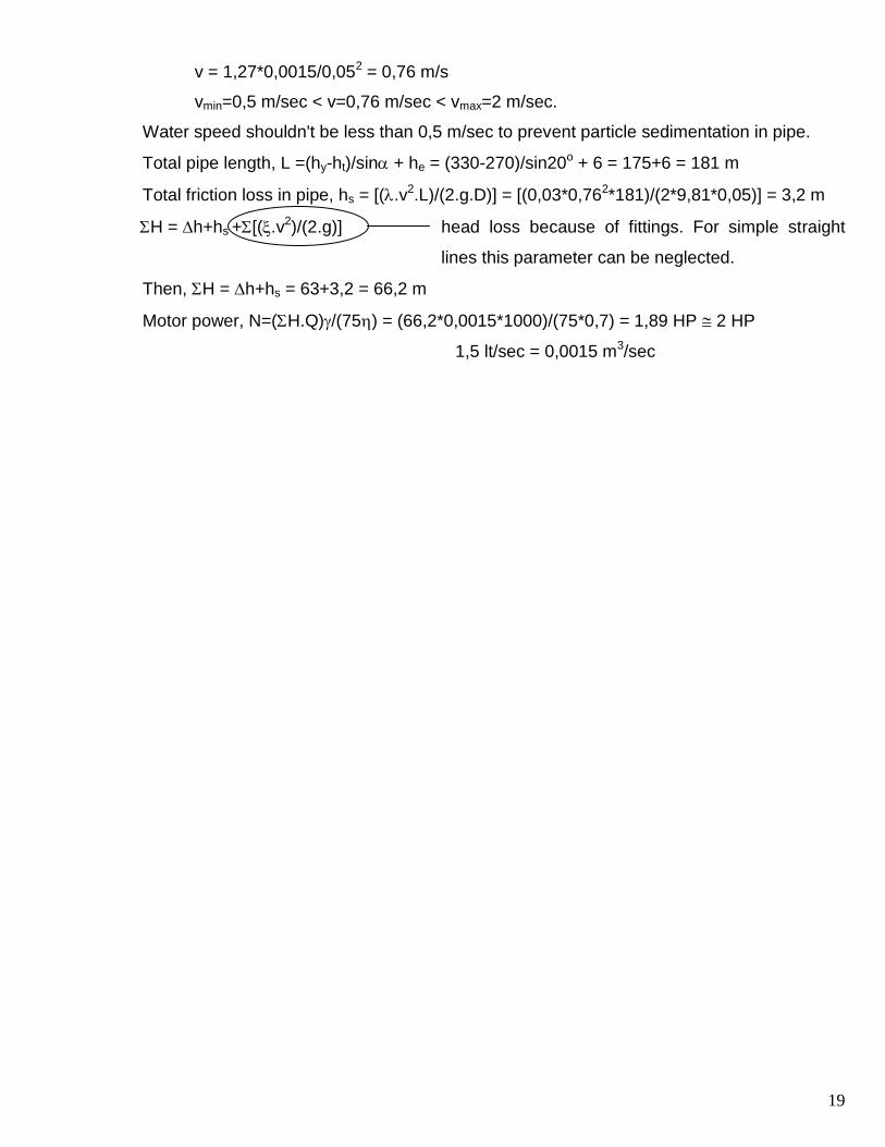
v = 1,27*0,0015/0,052 = 0,76 m/s
vmin=0,5 m/sec < v=0,76 m/sec < vmax=2 m/sec.
Water speed shouldn't be less than 0,5 m/sec to prevent particle sedimentation in pipe.
Total pipe length, L =(hy-ht)/sin + he = (330-270)/sin20o + 6 = 175+6 = 181 m
Total friction loss in pipe, hs = [(.v2.L)/(2.g.D)] = [(0,03*0,762*181)/(2*9,81*0,05)] = 3,2 m
H = h+hs +[(.v2)/(2.g)] head loss because of fittings. For simple straight
lines this parameter can be neglected.
Then, H = h+hs = 63+3,2 = 66,2 m
Motor power, N=(H.Q)/(75) = (66,2*0,0015*1000)/(75*0,7) = 1,89 HP 2 HP
1,5 lt/sec = 0,0015 m3/sec
20
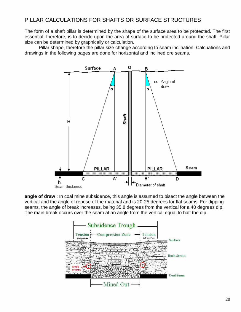
PILLAR CALCULATIONS FOR SHAFTS OR SURFACE STRUCTURES
The form of a shaft pillar is determined by the shape of the surface area to be protected. The first essential, therefore, is to decide upon the area of surface to be protected around the shaft. Pillar size can be determined by graphically or calculation.
Pillar shape, therefore the pillar size change according to seam inclination. Calcuations and drawings in the following pages are done for horizontal and inclined ore seams.
angle of draw : In coal mine subsidence, this angle is assumed to bisect the angle between the vertical and the angle of repose of the material and is 20-25 degrees for flat seams. For dipping seams, the angle of break increases, being 35.8 degrees from the vertical for a 40 degrees dip. The main break occurs over the seam at an angle from the vertical equal to half the dip.
21
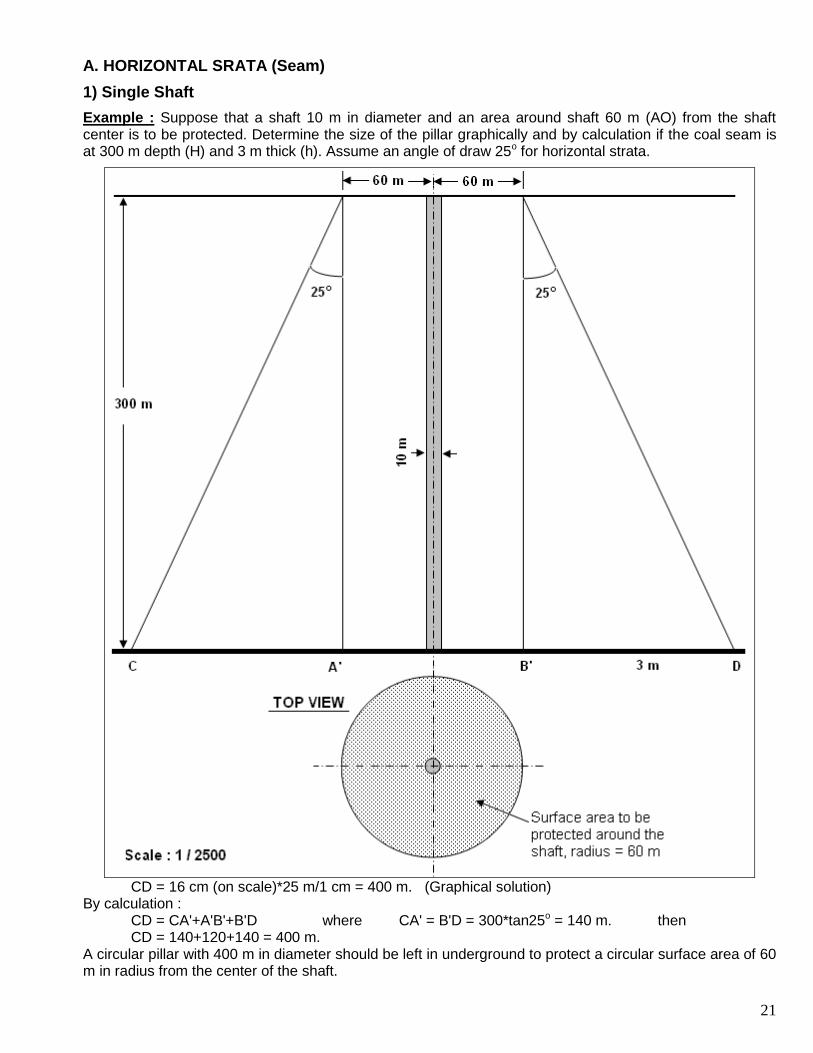
A. HORIZONTAL SRATA (Seam)
1) Single Shaft
Example : Suppose that a shaft 10 m in diameter and an area around shaft 60 m (AO) from the shaft center is to be protected. Determine the size of the pillar graphically and by calculation if the coal seam is at 300 m depth (H) and 3 m thick (h). Assume an angle of draw 25o for horizontal strata.
CD = 16 cm (on scale)*25 m/1 cm = 400 m. (Graphical solution) By calculation : CD = CA'+A'B'+B'D where CA' = B'D = 300*tan25o = 140 m. then CD = 140+120+140 = 400 m. A circular pillar with 400 m in diameter should be left in underground to protect a circular surface area of 60 m in radius from the center of the shaft.
22
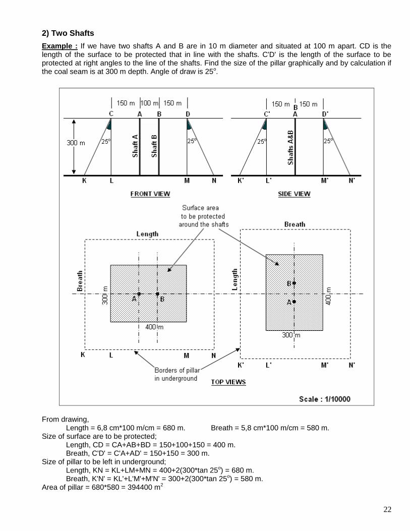
2) Two Shafts
Example : If we have two shafts A and B are in 10 m diameter and situated at 100 m apart. CD is the length of the surface to be protected that in line with the shafts. C'D' is the length of the surface to be protected at right angles to the line of the shafts. Find the size of the pillar graphically and by calculation if the coal seam is at 300 m depth. Angle of draw is 25o.
From drawing, Length = 6,8 cm*100 m/cm = 680 m. Breath = 5,8 cm*100 m/cm = 580 m. Size of surface are to be protected; Length, CD = CA+AB+BD = 150+100+150 = 400 m. Breath, C'D' = C'A+AD' = 150+150 = 300 m. Size of pillar to be left in underground; Length, KN = KL+LM+MN = 400+2(300*tan 25o) = 680 m. Breath, K'N' = KL'+L'M'+M'N' = 300+2(300*tan 25o) = 580 m. Area of pillar = 680*580 = 394400 m2
23
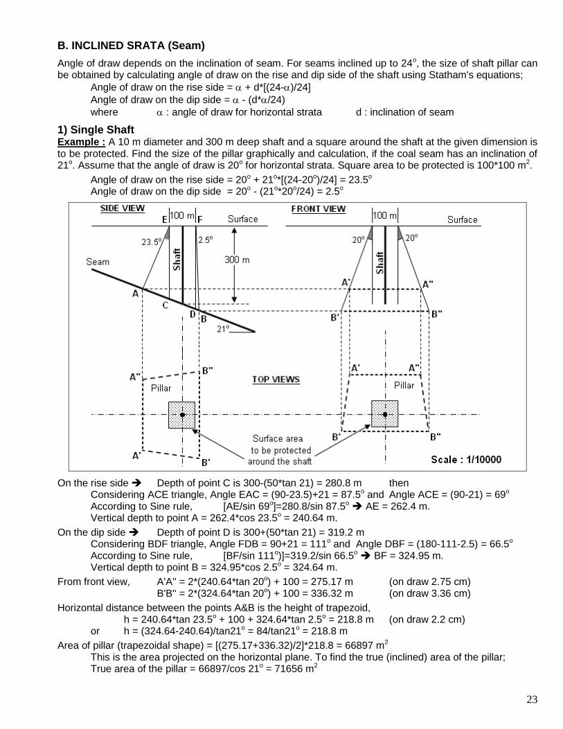
B. INCLINED SRATA (Seam)
Angle of draw depends on the inclination of seam. For seams inclined up to 24o, the size of shaft pillar can be obtained by calculating angle of draw on the rise and dip side of the shaft using Statham's equations;
Angle of draw on the rise side = + d*[(24-)/24]
Angle of draw on the dip side = - (d*/24)
where : angle of draw for horizontal strata d : inclination of seam
1) Single Shaft Example : A 10 m diameter and 300 m deep shaft and a square around the shaft at the given dimension is to be protected. Find the size of the pillar graphically and calculation, if the coal seam has an inclination of 21o. Assume that the angle of draw is 20o for horizontal strata. Square area to be protected is 100*100 m2.
Angle of draw on the rise side = 20o + 21o*[(24-20o)/24] = 23.5o Angle of draw on the dip side = 20o - (21o*20o/24) = 2.5o
On the rise side Depth of point C is 300-(50*tan 21) = 280.8 m then Considering ACE triangle, Angle EAC = (90-23.5)+21 = 87.5o and Angle ACE = (90-21) = 69o According to Sine rule, [AE/sin 69o]=280.8/sin 87.5o AE = 262.4 m. Vertical depth to point A = 262.4*cos 23.5o = 240.64 m.
On the dip side Depth of point D is 300+(50*tan 21) = 319.2 m Considering BDF triangle, Angle FDB = 90+21 = 111o and Angle DBF = (180-111-2.5) = 66.5o According to Sine rule, [BF/sin 111o)]=319.2/sin 66.5o BF = 324.95 m. Vertical depth to point B = 324.95*cos 2.5o = 324.64 m.
From front view, A'A'' = 2*(240.64*tan 20o) + 100 = 275.17 m (on draw 2.75 cm) B'B'' = 2*(324.64*tan 20o) + 100 = 336.32 m (on draw 3.36 cm)
Horizontal distance between the points A&B is the height of trapezoid, h = 240.64*tan 23.5o + 100 + 324.64*tan 2.5o = 218.8 m (on draw 2.2 cm) or h = (324.64-240.64)/tan21o = 84/tan21o = 218.8 m
Area of pillar (trapezoidal shape) = [(275.17+336.32)/2]*218.8 = 66897 m2 This is the area projected on the horizontal plane. To find the true (inclined) area of the pillar; True area of the pillar = 66897/cos 21o = 71656 m2
24
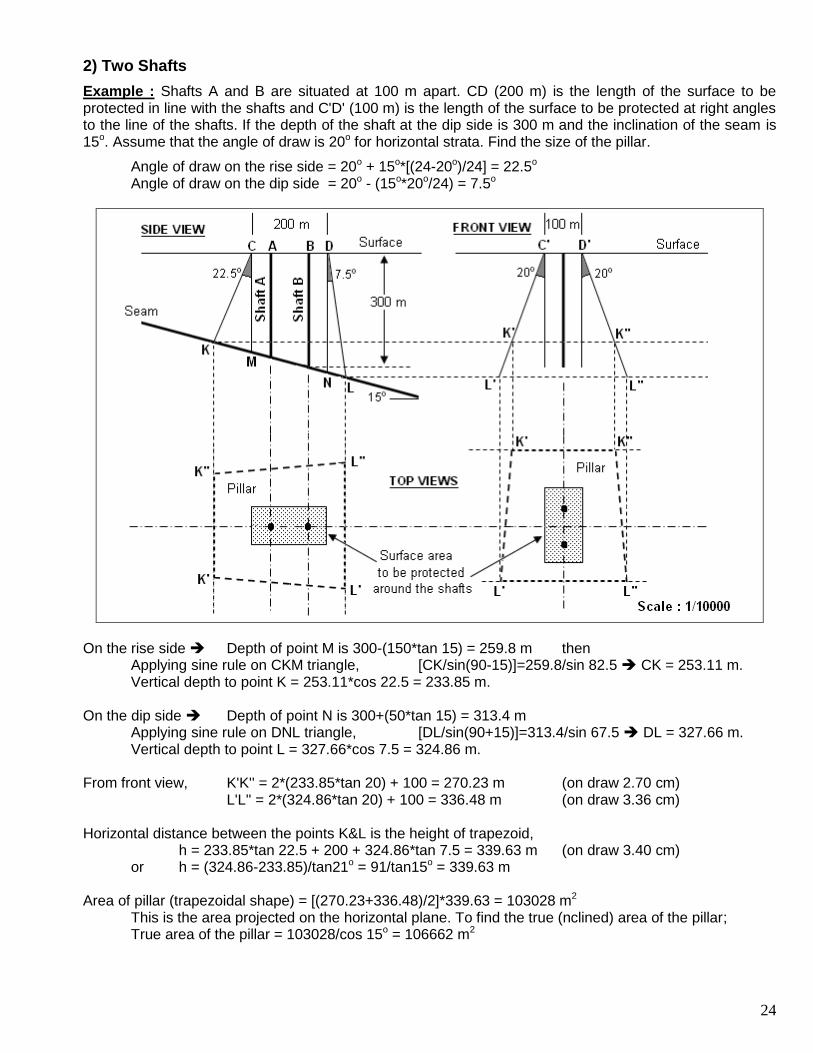
2) Two Shafts
Example : Shafts A and B are situated at 100 m apart. CD (200 m) is the length of the surface to be protected in line with the shafts and C'D' (100 m) is the length of the surface to be protected at right angles to the line of the shafts. If the depth of the shaft at the dip side is 300 m and the inclination of the seam is 15o. Assume that the angle of draw is 20o for horizontal strata. Find the size of the pillar.
Angle of draw on the rise side = 20o + 15o*[(24-20o)/24] = 22.5o Angle of draw on the dip side = 20o - (15o*20o/24) = 7.5o
On the rise side Depth of point M is 300-(150*tan 15) = 259.8 m then Applying sine rule on CKM triangle, [CK/sin(90-15)]=259.8/sin 82.5 CK = 253.11 m. Vertical depth to point K = 253.11*cos 22.5 = 233.85 m. On the dip side Depth of point N is 300+(50*tan 15) = 313.4 m Applying sine rule on DNL triangle, [DL/sin(90+15)]=313.4/sin 67.5 DL = 327.66 m. Vertical depth to point L = 327.66*cos 7.5 = 324.86 m. From front view, K'K'' = 2*(233.85*tan 20) + 100 = 270.23 m (on draw 2.70 cm) L'L'' = 2*(324.86*tan 20) + 100 = 336.48 m (on draw 3.36 cm) Horizontal distance between the points K&L is the height of trapezoid, h = 233.85*tan 22.5 + 200 + 324.86*tan 7.5 = 339.63 m (on draw 3.40 cm) or h = (324.86-233.85)/tan21o = 91/tan15o = 339.63 m Area of pillar (trapezoidal shape) = [(270.23+336.48)/2]*339.63 = 103028 m2 This is the area projected on the horizontal plane. To find the true (nclined) area of the pillar; True area of the pillar = 103028/cos 15o = 106662 m2