Embed Size (px)
Citation preview
DERIVING ARCHITECTURE DESIGN VARIANTS FOR SYSTEM OPTIMIZATIONFROM DESIGN SPACE DESCRIPTIONS EXPRESSED USING A UML PROFILE
Alexander WichmannFrancesco BediniRalph Maschotta
Armin Zimmermann
Technische Universität IlmenauDepartment of Computer Science and Automation
System and Software Engineering GroupPO-Box 100 565, 98684 Ilmenau, Germany
ABSTRACT
In complex (dynamic) systems, models are usually too complex for a direct evaluation, and simulationis the method of choice (indirect optimization). Another aspect is the structure of the design space forcomplex system. In a recent paper of the authors, an approach is presented for design space descriptionwith a UML profile-based description of architectural variations of complex dynamic systems. In order toexecute a simulation of a system variant, one has to be chosen based on the used heuristic, and specified in astandardized way to be used for constructing the actual simulation model with the use of a library of templatemodels. This paper approaches a method to automatically generated individual UML object models fromthe design space specification for a given parameter selection.
Keywords: UML profile, architecture design space description, system optimization, design variants
1 INTRODUCTION
Model-based systems design is an important help in the design process of complex systems and aims atreduced risks and better design decisions without the need to implement costly prototypes. In the end, eachengineering task can be viewed as an optimization problem of finding the best design alternative under givenconstraints. However, automatic optimization methods can often not be used because of the complexity ofthe problem field. Optimization of linear systems with numerical parameters is a well-understood area ofoperations research. However, in complex (dynamic) systems, models are usually too complex for a directevaluation, and simulation is the method of choice (indirect optimization) (van Leeuwen et al. 2014). Inorder to find the optimal system architectures, heuristic techniques can be used, which is an important andwidely covered research area (Liberti and Maculan 2006, Fu 1994, Carson and Maria 1997).
Another aspect is the structure of the design space — as long as it can be described as a multidimensionalspace with continuous or discrete numerical values, well-known heuristics such as simulated annealing canbe applied. This is not sufficient any more in all cases where the architecture of a system or choice of usedtechnology should be decided in an optimal way. Selecting a certain design parameter value (which decidesabout using a specific communication technology, for instance) may lead to additional parameters that only
SpringSim-Mod4Sim 2017, April 23-26, Virginia Beach, VA, USA©2017 Society for Modeling & Simulation International (SCS)
Wichmann, Bedini, Maschotta and Zimmermann
emerge because of this choice. In such less structured settings, it is already unclear how to describe thedesign space itself without enumerating the set of all variants (which is usually prohibitively large).
A solution for this problem has been proposed recently, with a UML profile-based description of architecturevariants of complex dynamic systems (Wichmann et al. 2017), which is depicted in Figure 1. This metamodel allows to describe multi-dimensional design spaces which may change their inner structure based oncertain parameter settings, among others. A model of a system can be structured as a class representingthe system. This system class has associations to component classes, which have properties and may haveassociations to other component classes. Variants of system component properties can be specified byvalue variant stereotypes, which extends the UML meta class Property. Properties can be classified intonumerical properties, optional properties, enumeration-based attributes, fixed attributes or derived attributes.For each category, a separate stereotype is defined, which owns different properties to specify the variants ofcorresponding Property element. In contrast to this, instance-based properties are specified by associationsand allow hierarchical variant specification of the associated class. To model such hierarchical relationsbetween classes, the UML meta class Dependency is extended with variant stereotypes in order to varyinstance-based properties, which are specified by associations to other classes. A Dependency relationdefines that a class depends on a single supplier class or set of supplier classes (OMG 2015). In general,variant specification of instance-based properties defines that instances of a supplier class should be assignedto a property of the depending class. How many instances should be created and how these instances areconfigured, should be defined through specializations. A detailed specification of this meta model extensioncan be found in (Wichmann et al. 2017).
«Stereotype» intervalValueVariant
min : Real [1]max : Real [1]step : Real [1]
«Stereotype» typeValueVariant
type : DataType [1]values : ValueSpecification [*]ordered : Boolean [1]
«Stereotype» listValueVariant
«Stereotype» derivedValueVariantformula : Behavior [1]
«Stereotype» fixedValueVariant
value : ValueSpecification [0..1]
«Stereotype» optionalValueVariant
«Metaclass»UML::Property
«Stereotype» derivedInstanceVariant
creationBehavior : Behavior [1]oppositeTarget : Property [0..1]variantClass : Class [*]
«Stereotype» instanceVariant
target : Property [1]uniqueInstances : Boolean [1]
«Metaclass»UML::Dependency
«Stereotype» countFixedInstanceVariant
instanceCount : Integer [1]instanceList : InstanceSpecification [*]
«Stereotype» countVariableInstanceVariant
minimalCount : Integer [1]maximalCount : Integer [1]step : Integer [1]instanceList : InstanceSpecification [*]
Figure 1: UML Profile diagram for System Architecture Variant Specification (Wichmann et al. 2017).
An approach of automatic indirect optimization method is already presented in (Wichmann et al. 2015),where possible system architecture variants are determined by heuristic optimization methods and evaluatedby simulating the system model iteratively. There are several possible approaches to implement an opti-mization heuristic: One is the classic implementation by using a standard programming language. In ourprevious work, this has already been done in the programming language C++. To model an optimizationprocess completely, both structure and behavior have to be described. The Eclipse Modeling Project (EMP)can be used for model-based development of domain-specific applications. In (Giese et al. 2009) a special

Wichmann, Bedini, Maschotta and Zimmermann
Story-Diagram, which is an enhancement on an activity diagram, is used to model the behavior of UMLclass diagrams. The Object Management Group (OMG) defines the fUML (Semantics Of A FoundationalSubset For Executable UML Models, (OMG 2013b)) to realize models with executable behavior. The au-thors of (Lazar et al. 2010) present a special action language for fUML activity diagrams. In another relatedwork, the Action Language for Foundational UML (ALF (OMG 2013a)) is used to describe the behaviorinside fUML models of cyber-physical systems (Gerlinger Romero et al. 2013).
An indirect optimization approach is realized using an approach of model-based specification of executablesystem optimization processes based on activity diagrams in our previous work (Wichmann et al. 2016).UML class diagrams and activity diagrams (OMG 2013b) are used to model structure and behavior of opti-mization processes of a system, which should be integrated into C++-based applications. A C++ represen-tation of the models are generated based on these models using a UML4CPP generator (Jäger et al. 2016).These classes can be used to execute the defined optimization process by using a C++ fUML-conform ex-ecution engine, which is defined in a model-based way and automatically generated as well (Bedini et al.2017) .
In order to execute a simulation of a system variant, one has to be chosen based on the used heuristic, andspecified in a standardized way to be used for constructing the actual simulation model. An open question isnow how to describe one selected variant in this way and how to interface the usually numerical parameterdescriptions of heuristics with such a less structured variant description.
This paper presents a method to automatically generate individual UML object models from the designspace specification. Technically, the Eclipse modeling project and the Sirius project are used which enablea more effective realization of domain-specific languages than other approaches (Eclipse 2014, El Kouhen,Amine and Dumoulin, Cedric and Gerard, Sébastien and Boulet, Pierre 2012). The paper is structured asfollows: The subsequent section specifies how to create different architecture variants depending on heuristicdecisions. Section 3 presents an architecture variants model of a communication system and its variationcreation as an example.
2 ARCHITECTURE VARIANT CREATION FOR HEURISTIC OPTIMIZATION METHODS
This section describes the approach of generating individual UML object models from a design space de-scription in support of system optimization.
2.1 Workflow for System Architecture Optimization
Figure 2 presents a workflow of system architecture optimization. To optimize a system architecture, thesystem design has to be modeled first. System components, their properties as well as their connections toother components are specified here. This is done using the widely accepted and standardized UML (OMG2015) and can be visualized with UML class diagrams. The system architecture optimization process re-quires information about how such a system design model can be varied in order to select an optimal systemarchitecture among these variants. For that, the previously introduced variant profile is applied to the systemdesign model. Variant-specific stereotypes are available inside the model for this purpose and can be usedto describe value variants as well as instance variants. The resulting model is called architecture variantsmodel (Wichmann et al. 2017).
An architecture variants model describes the design space of all possible architecture variants, which hasto be given by the system designer and is used as an input for the system optimization process. Duringexecution of system architecture optimization, a heuristic is executed iteratively and creates and evaluates

Wichmann, Bedini, Maschotta and Zimmermann
create system architecture
optimized systemarchitecture
create architecturevariants model
execute systemarchitectureoptimization
create systemdesign
System designmodel
Architecturevariants model
:Profile<<datastore>>
variantsProfile
Figure 2: Main Steps in Architecture Optimization.
architecture variants in order to find the best system architecture. The approach of creation system architec-ture variants is specified in Section 2.4.
In our UML setting, system architecture variants are instances of the architecture variants model (Wichmannet al. 2017). The OMG defines the class InstanceSpecification inside the UML specification to describe in-stances of a modeled system. In general, InstanceSpecification represents an instance of a UML Classifierlike Class or Interface. InstanceSpecification includes the property classifier, defining which Classifier isrepresented. Each Property of a Classifier is assigned an explicit value by using a UML ValueSpecificationinterface. ValueSpecification is used to assign an explicit value to a specific property. Values of primi-tive types are configured using LiteralSpecification and its specializations. Enumeration and instances ofassociated classifiers are described by InstanceValue, which includes references to corresponding Instance-Specification elements. Details for the specification of each element can be found in the UML specifica-tion OMG2013b.
However, InstanceSpecification is used for the description of an architecture variant. As a standardizedelement of UML, it is suitable as an interface between heuristic and architecture generator. The task of anarchitecture generator is to generate a simulation model of a current architecture variant. Thus, this generatorrequires knowledge about the used simulation tool in order to build valid simulation models. The heuristicis independent of simulation-specific information by using InstanceSpecification as the interface, and canbe used for several simulation tools without additional effort. Furthermore, the use of InstanceSpecificationas interface allows easy exchange of architecture generators as well as the used heuristics.
2.2 Top-level Behavior of Heuristic Execution
The action execute system architecture optimization of Figure 2 realizes an approach of indirect optimiza-tion (Wichmann et al. 2016) in model-based way. This approach uses a heuristic to create architecturevariants. The general top-level behavior of a heuristic is described by an activity diagram, which is shown inFigure 3. Three ingoing activity parameter nodes and one outgoing activity parameter are used. The ingoingnodes for termination condition and architecture variants model are placed on top of the activity. This datais not changed during the whole optimization process, but a token has to be put on this node (given by Data-StoreNode) in order to fulfill UML-conform activity execution behavior. The third ingoing parameter nodeprovides the result of the last loop execution (or invalid result at first execution). An architecture variant isplaced on the outgoing parameter node. This variant can be a newly created one, which should be evaluated,or the best found architecture variant, if the overall optimization is finished.
If the heuristic is executed for the first time, an architecture variant is created randomly. How this task isdone, is described in Section 2.4. Otherwise, the current evaluation result is compared to the result of thecurrent best variant using an objective function that should be maximized or minimized. A heuristic-specifictermination condition is checked afterwards. If this condition is fulfilled, the algorithm is finished and the

Wichmann, Bedini, Maschotta and Zimmermann
ExecuteHeuristic .
: Evaluation-Result
termination condition architecture variantmodel
: Instance-Specification
createInstanceSpecification
check terminationcondition
modifyInstanceSpecification
get root class fromvariant model
rootClass :Class
: Instance-Specification
[else]
[termination conditionis fulfilled]
[firstExecution== true]
[else]
Figure 3: Top level behavior of heuristic.
resulting best variant is placed on the outgoing activity parameter node. Otherwise, the architecture variantis modified, which is described in Section 2.5, and the iteration loop starts over.
2.3 Software Design of Architecture Variant Creation
This section describes the class structure of the architecture variant creation during the presented optimiza-tion loop execution. Figure 4 presents the corresponding class diagram of this approach. Architecture vari-ants are calculated by a heuristic, which implements the interface XHeuristic. The interface provides thefunction execute, which is executed inside the optimization loop and implemented by class BaseHeuristic.This class provides basic functionality for checking termination conditions, comparison of the current archi-tecture variant against previous and best variants, as well as creating the next architecture variant. This classshould be inherited from and thus specialized by example heuristics such as simulated annealing, which willuse the provided functionality and add their specific behavior or overwrite the defaults of BaseHeuristic.
InstanceSpecificationGeneratorrandomGenerator : XRandomGeneratorInstanceSpecificationGenerator(randomGenerator :
XRandomGenerator)createInstanceSpecification(aClass : Class) :
InstanceSpecificationupdateValueSpecification(parent : InstanceSpecification,
property : Property, difference : Real)createInstanceValue(parent : InstanceSpecification,
property : Property, class : Class)removeInstanceValue(parent : InstanceSpecification,
property : Property, index : Integer)
«interface»XNumberGenerator
requestValue(minimalValue : Real, maximalValue : Real, step : Real) : Real
BaseHeuristic
instSpecGenerator : InstanceSpecificationGenerator randomGenerator : XRandomGenerator
«interface»XHeuristic
execute(evaluationResult : EvaluationResult) : ArchitectureVariant
RandomGenerator<<create>>
randomGenerator
instSpecGenerator
randomGenerator
Figure 4: Class structure of architecture variant creation approach.

Wichmann, Bedini, Maschotta and Zimmermann
BaseHeuristic owns a reference to an XNumberGenerator interface, which is used to choose a numberbased on a given interval. The interface is realized by a random generator with uniform distribution. Al-ternatively, a random number generator with Gaussian distribution or even deterministic generator can beused for instance. The heuristic should specify its required type of distribution. Furthermore, there is anInstanceSpecificationGenerator, whose instance is assigned to BaseHeuristic. Additionally, InstanceSpec-ificationGenerator includes a reference to an XNumberGenerator, which is handed over in the constructorby the heuristic. In addition to the creation of UML conform InstanceSpecification instances, the task of In-stanceSpecificationGenerator is to manipulate existing InstanceSpecification instances according to inputsof the heuristic.
2.4 Creation of Architecture Variants
This section specifies the behavior to create an individual architecture variant. The architecture variantsmodel may specify a root class, at which the variant creation should start. If such a root class is not specified,the variants model is searched for a class, which is not owned by another class. If such a class is found, it isused as root class. Otherwise, the algorithm cannot be executed and the optimization fails.
CreateInstanceSpecification
: Class : InstanceSpecification
getOwnedAttributes
createUMLInstanceSpecification
getClientDependency
createValueSpecification
createInstanceValue
setInstance-SpecificationSlots: InstanceSpecification
: Dependency[*] Slot[*]
Slot[*]: Property[*]
*
*
: Class
: Class
Figure 5: Behavior of Instance Specification Creation.
Figure 5 presents an activity diagram specifying the top-level behavior for variant creation, which is executedwith a root class as the input parameter. The variant is created in three steps, which can be carried out inparallel: The first step is to create an instance of UML InstanceSpecification, which represents a specificUML class. Thus, InstanceSpecification owns property classifier, which includes a reference to the classgiven as ingoing parameter.
Secondly, a list of all owned attributes are selected from Class parameter. For each element of resultingProperty list, action createValueSpecification is executed. How does a value, which should be assignedto current Property instance, is determined? All stereotypes, which are applied to the Property instance,are selected. Variant stereotypes, which extend UML meta class Property are analyzed here. If stereotypeintervalValueVariant is applied, a value is selected by use of XNumberGenerator’s function requestValue(...).The required parameters are already defined inside the stereotype. A UML LiteralReal is created and theselected value is assigned to it. Furthermore, a slot is created with references to the Property instance andLiteralReal instance. For stereotype listValueVariant, a value is requested in the same way. In difference tothe previous stereotype, a list with a size corresponding to the value is created instead of a single literal.
Another stereotype is optionalValueVariant, which results in a Boolean literal as its value specification. Thedecision, which Boolean value should be used, is simply chosen with interval [0,1] with step 1. Thus, theresult of XNumberGenerator execution can be either ’0’ or ’1’. The last stereotype with variants possibility iscalled typeValueVariant. Since values can also include non-numeric values or values with different distances,a value request directly based on the list values is not possible. Alternatively, the value selection is done

Wichmann, Bedini, Maschotta and Zimmermann
indirectly via the list index. An index is chosen by the XNumberGenerator and the value, which is placedon this index, is assigned to the slot corresponding to the Property instance.
Stereotype derivedValueVariant includes a behavior, which calculates a value deterministically. This be-havior is executable by using fUML execution engine. Thus, the required value can calculated here. If thestereotype fixedValueVariant is assigned to the Property instance, a ValueSpecification is already defined andis assigned to the slot here. If no variant stereotype is applied to a Property, but a default value is specified,this value will be used. Otherwise, LiteralNull is applied to the corresponding slot instance, meaning thatno value is defined explicitly.
In a similar way, the third step creates variants, which are described by instance variant stereotypes. For that,all client dependencies are selected from Class parameter and InstanceValue instances are created based onapplied stereotype. Stereotype countFixedInstanceVariant defines a fixed count of instances of a supplierclass, which should be created. It is possible, that InstanceSpecification instances are already preconfigured,which are used instead of creating new instances. Each preconfigured InstanceSpecification is checked, ifall class properties are existing and assigned to a ValueSpecification. If a property is missing, it is createdby the InstanceSpecificationGenerator. Similarly, countVariableInstanceVariant is processed, in which theinstance count is chosen by XNumberGenerator. In a similar way to derivedValueVariant, the stereotypederivedInstanceVariant owns a creation behavior, which is executed for all combinations of input instances.Finally, action setInstanceSpecificationSlots inserts the results of the second and third step into the createdInstanceSpecification.
2.5 Modifications of Architecture Variants
After creating the first architecture variant, further variants may be computed by changing the previous vari-ant in at least one property of an InstanceSpecification or even adding or removing an InstanceSpecification.For some optimization heuristics a notion of distance between parameter values is assumed (temperature-based selection of next parameter value in simulated annealing, for instance). This assumption cannot easilybe transferred to our complex architecture variants, where there may not be any relation depending on theorder of settings. This problem will be tackled in future work; for the moment, we assume that the encodingsequence of values is exploited.
ModifyInstanceSpecification
ArchitectureVariant
ArchitectureVariants Model
modify systemstructure
select variableproperties
<<structured>>Loop
Setup
Test
Body
: Instance-Specification
: Property[*]
is property list notempty && steps > 0
selectproperty
choose valuedifference
modify propertyvalue
: Property
: double
: Instance-Specification
Figure 6: Behavior of Architecture Variant Modification.
To make matters worse, such a distance may be needed also for the complex multi-dimensional designspace, and it would not make sense to use space-geometrical (Pythagorean) assumptions on parameters.Instead, we assume here that one step in one parameter is ’as important’ as any other parameter step, and

Wichmann, Bedini, Maschotta and Zimmermann
thus propose to apply Manhattan distance as an approximation of ’how distant’ two parameter settings are(i.e., variants, or points on the design space). One step is defined as the minimal difference of propertyvalues, which is specified also for real-valued parameters. A minimal difference for intervalValueVariantis defined by its property step for instance. One value step of typeValueVariant-properties is defined as anindex increment or decrement. For countVariableInstanceVariant stereotypes, the minimal step is definedby adding or removing one instance. For each heuristic execution, a calculated step count is available, whichcan be used to modify the architecture variant. The actual count calculation has to be defined adaptively byspecialized heuristics if necessary.
Figure 6 proposes the behavior for modifying an architecture variant using an activity diagram in two steps.Structural modifications on InstanceSpecification instances are performed first. For that, all combinationsof countVariableInstanceVariant-based instance counts are calculated. XNumberGenerator is used to selectone out of this combination set. InstanceSpecification instances are created or deleted depending on theselection result. The step count is decreased by the number of InstanceSpecification creations and deletions.The remaining step count is used to change property values of existing InstanceSpecification instances. Alist of all properties with value variant stereotype is received by InstanceSpecificationGenerator. While thestep count is greater than zero and there are still unmodified properties, a property and a difference value aswell as the direction of change is selected randomly using XNumberGenerator. The value setting is done byusing InstanceSpecificationGenerator.
All presented methods are realized model-based using fUML and is completely executable.
3 AN APPLICATION EXAMPLE
This section describes the derivation of concrete system variant instances for a simplified communica-tion network, in which network nodes communicate using wired and wireless communication protocols.This communication network and the following communication network variants model has been presentedin (Wichmann et al. 2017). An EndNode can be a server, personal computer or other gadgets and producesdata, which should be sent to another EndNode. For that, EndNode instances can provide WLAN tech-nique or Ethernet slots. Additionally, AccessPoint instances could be used to cover large distance betweenEndNode or as connection of WLAN-based and Ethernet-based communication.
3.1 Communication network variants
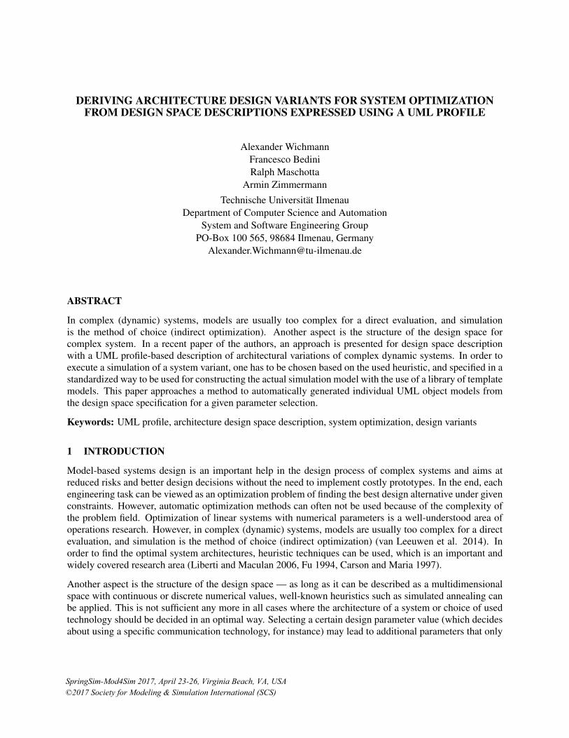
Figure 7 presents an architecture variants model, which is used by a system optimization process in orderto find the best architecture. A Network includes instances of Interface NetworkNode, which is realized byclasses EndNode and AccessPoint. To specify the count of class instances, which should be owned by Net-work, Dependency connections are created between Network and EndNode as well as AccessPoint. EndNodeis preconfigured with instance specifications and should not be varied. The first EndNode represents a smartphone providing WLAN features, but not having an Ethernet port. The other EndNode instance is a personalcomputer with one Ethernet port and without WLAN. This information is specified by using the variantstereotype countFixedInstanceVariant.
AccessPoint instances can be varied in their number as well as their properties. For that, stereotype count-VariableInstanceVariant is applied to the Dependency connection. At least one and not more than threeAccessPoint instances may exist. Additionally, several properties of AccessPoint are varied, which is spec-ified by value variant stereotypes. Position of AccessPoint and count of Ethernet ports are specified byintervalValueVariant. Furthermore, WLAN feature is defined as optional. Connections are established be-tween two nodes, in which a connection can be realized by WLANConnection or LANConnection. Whichconnection is to be created, is defined by stereotype derivedInstanceSpecification. This stereotype owns a
Wichmann, Bedini, Maschotta and Zimmermann
«variant»CommunicationNetwork
EndNodedatarateMean : Real [1] = 5.0datarateVariance : Real [1] = 50.0
«interface»Connection
dataRate : Real [1]networkNodes : NetworkNode [2]
WLANConnection«derivedValueVariant» distance : Real [1]maxRange : Real [1] = 50.0dataRate : Real [1] = 50.0
NetworknetworkNodes : NetworkNode [*]
AccessPoint«intervalValueVariant» countLANPorts : Integer [1]«optionalValueVariant» isWLANExisting : Boolean [1]«intervalValueVariant» position_x : Integer [1]«intervalValueVariant» position_y : Integer [1]«intervalValueVariant» position_z : Integer [1]
LANConnectiondataRate : Real [1] = 100.0
«interface»NetworkNode
name : String [1]position_x : Integer [1]position_y : Integer [1]position_z : Integer [1]countLANPorts : Integer [1] = 0isWLANExisting : Boolean [1] = falseconnections : Connection [*]
<<countFixedInstanceVariant>>
<<countVariableInstanceVariant>>
<<derivedInstanceVariant>>
networkNodes[2]connections[*]
networkNodes[*]rootClass = <class> Network
target = <Property> NetworkNode::connectionsuniqueInstances = truecreationBehavior = <Activity> CreateConnectionvariantClass = {WLANConnection, LANConnection}oppositeTarget = Connection::networkNodes
target = <Property> Network::networkNodesuniqueInstances = trueinstanceCount = 2instanceList = {node1, node2}
formula = <FunctionBehavior> calculateDistance
min max stepcountLANPorts 0 4 1position_x 0 1000 200position_y 0 500 100positoin_z 0 200 100
target = <Property> Network::networkNodesminimalCount = 1maximalCount = 3step = 1instanceList = {}
Figure 7: Architecture Variants Model for a Communication Network (Wichmann et al. 2017).
creation behavior, which is executed for each combination of two NetworkNode instances. This behaviorspecifies that a WLANConnection can only be created if both nodes provide WLAN. Similarly, a LANCon-nection requires a free Ethernet slot on each node. If both connections are possible, the decision can beinfluenced by the heuristic.
3.2 Resulting InstanceSpecification instances
The presented approach for deriving concrete system variant instances is specified in a UML-conform wayin our system optimization model. Similarly, the architecture variants model is set up as a UML model usingthe variant profile. In order to execute this, our UML4CPP generator (Systems and Software EngineeringGroup 2016) is used to transform the models into executable C++ code, which is compilable without furtherimplementation efforts. Finally, the resulting system optimization application is executable through theuse of our fUML-conform execution engine. The optimization process is executed and several architecturevariants are generated based on the architecture variants model of the communication network.
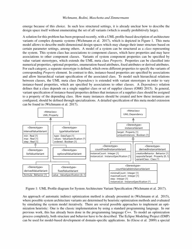
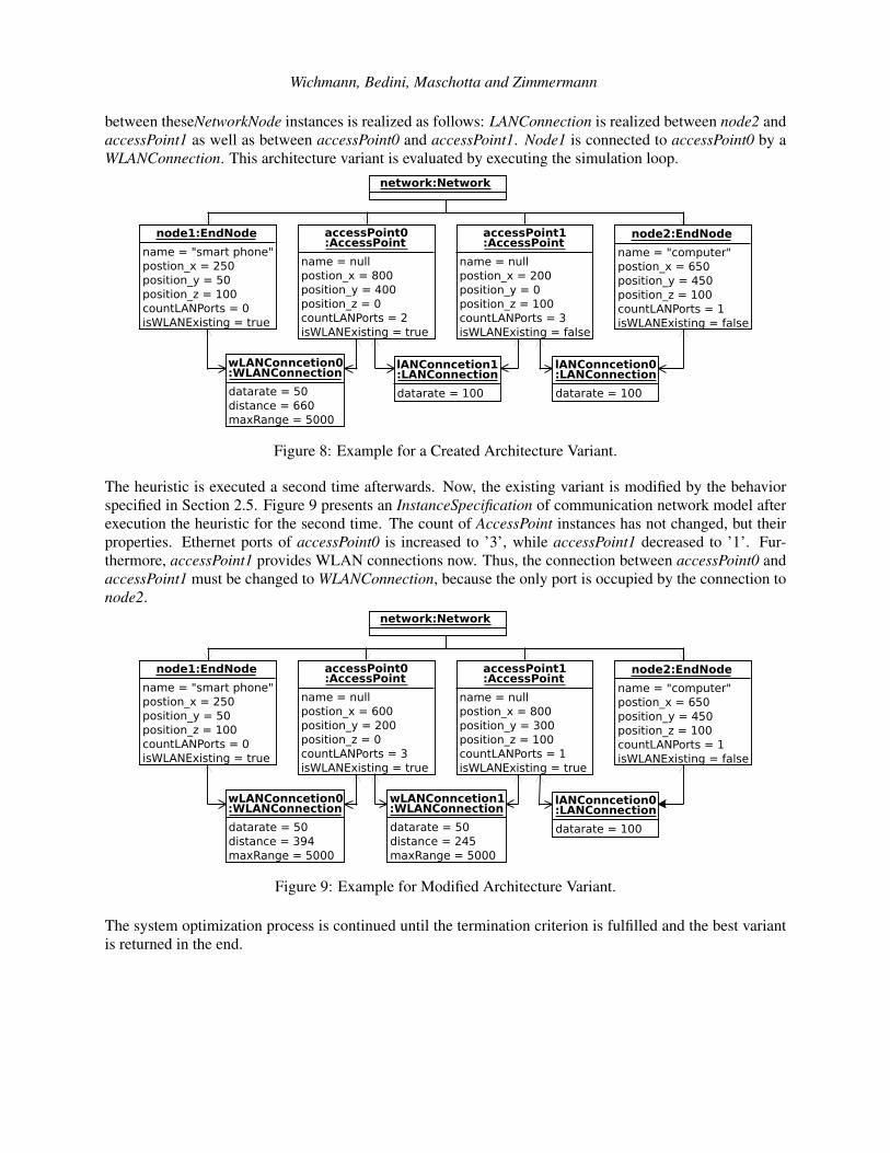
The heuristic is executed for the first time. Thus, a first variant has to be created by executing the behaviorpresented in Section 2.4. Figure 8 shows the resulting architecture variant as an example. A network in-cludes two preconfigured EndNode instances as well as two AccessPoint instances. An AccessPoint supportsWLAN and two Ethernet ports. The other AccessPoint has three Ethernet ports, but no WLAN. Connections
Wichmann, Bedini, Maschotta and Zimmermann
between theseNetworkNode instances is realized as follows: LANConnection is realized between node2 andaccessPoint1 as well as between accessPoint0 and accessPoint1. Node1 is connected to accessPoint0 by aWLANConnection. This architecture variant is evaluated by executing the simulation loop.
network:Network
wLANConncetion0:WLANConnection
datarate = 50distance = 660maxRange = 5000
lANConncetion1:LANConnection
datarate = 100
node1:EndNode
name = "smart phone"postion_x = 250position_y = 50position_z = 100countLANPorts = 0isWLANExisting = true
node2:EndNode
name = "computer"postion_x = 650position_y = 450position_z = 100countLANPorts = 1isWLANExisting = false
accessPoint0:AccessPoint
name = nullpostion_x = 800position_y = 400position_z = 0countLANPorts = 2isWLANExisting = true
accessPoint1:AccessPoint
name = nullpostion_x = 200position_y = 0position_z = 100countLANPorts = 3isWLANExisting = false
datarate = 100
lANConncetion0:LANConnection
Figure 8: Example for a Created Architecture Variant.
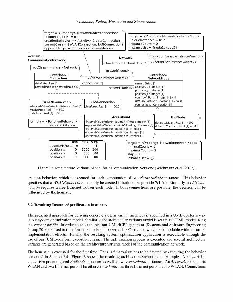
The heuristic is executed a second time afterwards. Now, the existing variant is modified by the behaviorspecified in Section 2.5. Figure 9 presents an InstanceSpecification of communication network model afterexecution the heuristic for the second time. The count of AccessPoint instances has not changed, but theirproperties. Ethernet ports of accessPoint0 is increased to ’3’, while accessPoint1 decreased to ’1’. Fur-thermore, accessPoint1 provides WLAN connections now. Thus, the connection between accessPoint0 andaccessPoint1 must be changed to WLANConnection, because the only port is occupied by the connection tonode2.
node1:EndNode
name = "smart phone"postion_x = 250position_y = 50position_z = 100countLANPorts = 0isWLANExisting = true
node2:EndNode
name = "computer"postion_x = 650position_y = 450position_z = 100countLANPorts = 1isWLANExisting = false
accessPoint0:AccessPoint
name = nullpostion_x = 600position_y = 200position_z = 0countLANPorts = 3isWLANExisting = true
accessPoint1:AccessPoint
name = nullpostion_x = 800position_y = 300position_z = 100countLANPorts = 1isWLANExisting = true
network:Network
wLANConncetion0:WLANConnection
datarate = 50distance = 394maxRange = 5000
wLANConncetion1:WLANConnection
datarate = 50distance = 245maxRange = 5000
lANConncetion0:LANConnection
datarate = 100
Figure 9: Example for Modified Architecture Variant.
The system optimization process is continued until the termination criterion is fulfilled and the best variantis returned in the end.
Wichmann, Bedini, Maschotta and Zimmermann
4 CONCLUSION
The paper presents an approach for deriving concrete design variant instances from architecture design spacedescriptions based on a UML profile, with the goal of supporting automatic system architecture optimization.The behavior for creating architecture variants is specified by standard UML meta model elements, which isexecutable by the application of our UML4CPP generator and C++ fUML-conform execution engine. Thederivation of design variants is shown with a simplified communication network model.
Future steps include the investigation of optimization methods suitable for system architectures. The opti-mization loop will be further refined, in particular for variant evaluations with complex objective functionsdefined on the model. Furthermore, constraints should be added to the variant model in order to allow formalvalidity checks for system variants.
REFERENCES
Bedini, F., R. Maschotta, A. Wichmann, S. Jäger, and A. Zimmermann. 2017. “A Model-Driven C++-fUMLExecution Engine”. In 5th Int. Conference on Model-Driven Engineering and Software Development,MODELSWARD 2017. Technische Universität Ilmenau. accepted for publication.
Carson, Y., and A. Maria. 1997. “Simulation Optimization: Methods And Applications”. In Proc. of the29th Winter Simulation Conference, WSC ’97, pp. 118–126.
Eclipse 2014. “Sirius”. http://www.eclipse.org/sirius/.
El Kouhen, Amine and Dumoulin, Cedric and Gerard, Sébastien and Boulet, Pierre 2012. “Evaluation ofModeling Tools Adaptation”. Available: https://hal.archives-ouvertes.fr/hal-00706701.
Fu, M. C. 1994. “A Tutorial Overview of Optimization via Discrete-Event Simulation”. In 11th Int. Conf.on Analysis and Optimization of Systems, edited by G. Cohen and J.-P. Quadrat, Volume 199 of LectureNotes in Control and Information Sciences, pp. 409–418. Sophia-Antipolis, Springer-Verlag.
Gerlinger Romero, A., K. Schneider, and M. Goncalves Vieira Ferreira. 2013, Sept. “Towards the applicabil-ity of alf to model Cyber-Physical Systems”. In Computer Science and Information Systems (FedCSIS),2013 Federated Conference on, pp. 1427–1434.
Giese, H., S. Hildebrandt, and A. Seibel. 2009, 0. “Improved Flexibility and Scalability by Interpreting StoryDiagrams”. In Proceedings of the Eighth International Workshop on Graph Transformation and VisualModeling Techniques (GT-VMT 2009), edited by T. Magaria, J. Padberg, and G. Taentzer, Volume 18,Electronic Communications of the EASST.
Jäger, S., R. Maschotta, T. Jungebloud, A. Wichmann, and A. Zimmermann. 2016. “An EMF-like UMLGenerator for C++”. In 4th Int. Conference on Model-Driven Engineering and Software Development,MODELSWARD 2016. Technische Universität Ilmenau. submitted for publication.
Lazar, C.-L., I. Lazar, B. Parv, S. Motogna, and I.-G. Czibula. 2010. “Tool Support for fUML Models”. InInt. J. of Computers, Communications & Control.
Liberti, L., and N. Maculan. 2006. Global Optimization: From Theory to Implementation. Springer Verlag.
OMG 2013a. “Concrete Syntax for a UML Action Language: Action Language for Foundational UML”.Technical report, Object Management Group.
OMG 2013b. “Semantics of a Foundational Subset for Executable UML Models”. Technical report, ObjectManagement Group.
OMG 2015. “Unified Modeling Language (OMG UML), Version 2.5”. Technical report, Object Manage-ment Group.
Wichmann, Bedini, Maschotta and Zimmermann
Systems and Software Engineering Group 2016. “Model Driven Engineering for C++ (MDE4CPP), sse.tu-ilmenau.de/mde4cpp”.
van Leeuwen, C., J. de Gier, J. O. de Filho, and Z. Papp. 2014. “Model-Based Architecture Optimization forSelf-Adaptive Networked Signal Processing Systems”. In SASO 2014 - 8th IEEE International Confer-ence on Self-Adaptive and Self-Organizing Systems.
Wichmann, A., S. Jäger, T. Jungebloud, R. Maschotta, and A. Zimmermann. 2015. “System ArchitectureOptimization With Runtime Reconfiguration of Simulation Models”. In IEEE International SystemsConference (SYSCON’15). Technische Universität Ilmenau.
Wichmann, A., S. Jäger, T. Jungebloud, R. Maschotta, and A. Zimmermann. 2016. “Specification and Exe-cution of System Otimization Processes with UML Activity Diagrams”. In IEEE International SystemsConference (SYSCON’16). Technische Universität Ilmenau.
Wichmann, A., R. Maschotta, F. Bedini, S. Jäger, and A. Zimmermann. 2017. “A UML Profile for theSpecification of System Architecture Variants Supporting Design Space Exploration and Optimization”.In 5th Int. Conference on Model-Driven Engineering and Software Development, MODELSWARD 2017.Technische Universität Ilmenau. accepted for publication.
AUTHOR BIOGRAPHIES
ALEXANDER WICHMANN received the Master’s degree in Computer Science from the TechnischeUniversität Ilmenau, Germany, in 2013. He is currently working towards the Ph.D. degree in the Sys-tems and Software Engineering Group of Technische Universität Ilmenau. His main research interestsinclude model-based specification and execution of system optimization processes. His email address [email protected].
FRANCESCO BEDINI received the Master’s degree in Research in Computer and Systems Engineeringwith distinction from Technische Universität Ilmenau in 2016. He is currently working towards the Ph.D.degree in the Systems and Software Engineering Group of TU Ilmenau. His main research interests in-clude efficient generation of code from UML and fUML models and their validation. His email address [email protected].
RALPH MASCHOTTA received the Diploma degree in technical computer science from the Universityof Applied Sciences Schmalkalden, Germany, in 1999 and the Ph.D. degree from Technische UniversitätIlmenau, Germany, in 2008. Since 2011, he has been a senior scientist and lecturer with the Systemsand Software Engineering Group, Faculty of Computer Science and Automation, TU Ilmenau. His mainresearch interests include object-oriented programming, modeling, and design of software systems, as wellas image processing and image recognition in medical and industrial applications. His email address [email protected].
ARMIN ZIMMERMANN received the Diploma, Ph.D., and Habilitation degrees from Technische Uni-versität Berlin, Germany, in 1993, 1997, and 2006, respectively. He has been a full Professor of systemsand software engineering since 2008 and the director of the Institute for Computer and Systems Engineeringsince 2012 with Technische Universität Ilmenau, Germany. His research interests include discrete eventsystem modeling and performance evaluation and their tool support with embedded systems applications.He is a member of the Industrial Automated Systems and Controls Subcommittee of the IEEE IES TechnicalCommittee on Factory Automation. His email address is [email protected].
This work was supported by the Federal Ministry of Economic Affairs and Energy of Germany [20K1306D] and FederalMinistry for Education and Research of Germany [01S13031A].