Embed Size (px)
Citation preview
Derivation and Real World Use of DQ Transform for Motor Drives
Presented to IEEE Power Electronics SocietySan Francisco Bay Area Chapter
ByTony O’Gorman
[email protected] February 2018
PESC Inc
PESC Inc
Agenda
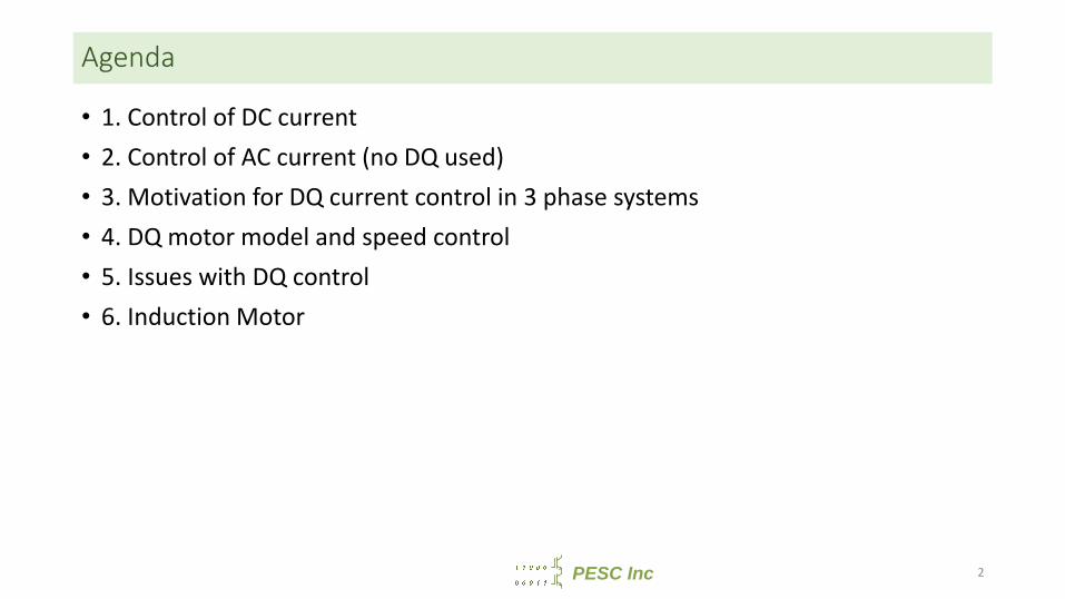
• 1. Control of DC current• 2. Control of AC current (no DQ used)• 3. Motivation for DQ current control in 3 phase systems• 4. DQ motor model and speed control• 5. Issues with DQ control• 6. Induction Motor
2
PESC Inc
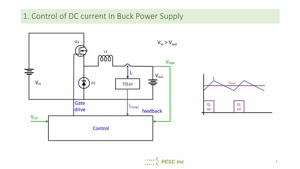
1. Control of DC current in Buck Power Supply
ILIL(avg)
Q1 on
Q1 on
L1
Q1
D1
Control
Vout
Vin
IL
feedbackGate drive
filter
IL(avg)
Vfdbk
Vref
Vin > Vout
3
PESC Inc
Control of DC Current in Buck Power Supply
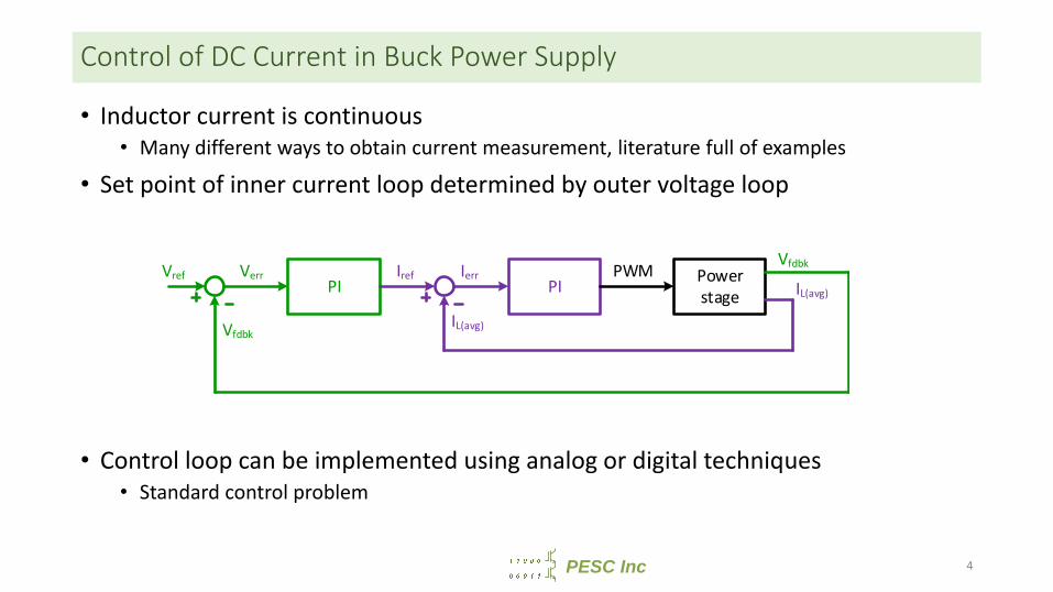
• Inductor current is continuous• Many different ways to obtain current measurement, literature full of examples
• Set point of inner current loop determined by outer voltage loop
• Control loop can be implemented using analog or digital techniques• Standard control problem
PI PI Power stage
PWMVref
Vfdbk
Verr Iref
IL(avg)
VfdbkIerrIL(avg)
4
PESC Inc
Agenda
• 1. Control of DC current• 2. Control of AC current (no DQ used)• 3. Motivation for DQ current control in 3 phase systems• 4. DQ Motor Model and speed control• 5. Issues with DQ control• 6. Induction Motor
5
PESC Inc
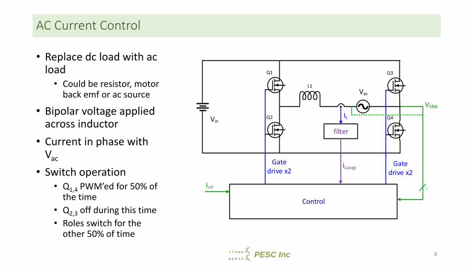
AC Current Control
• Replace dc load with ac load• Could be resistor, motor
back emf or ac source
• Bipolar voltage applied across inductor
• Current in phase with Vac
• Switch operation• Q1,4 PWM’ed for 50% of
the time• Q2,3 off during this time• Roles switch for the
other 50% of time
L1
Q1
Control
VinIL
Gate drive x2
filter
IL(avg)
Vfdbk
Iref
Q2
Q3
Q4
Gate drive x2
Vac
2
6
PESC Inc
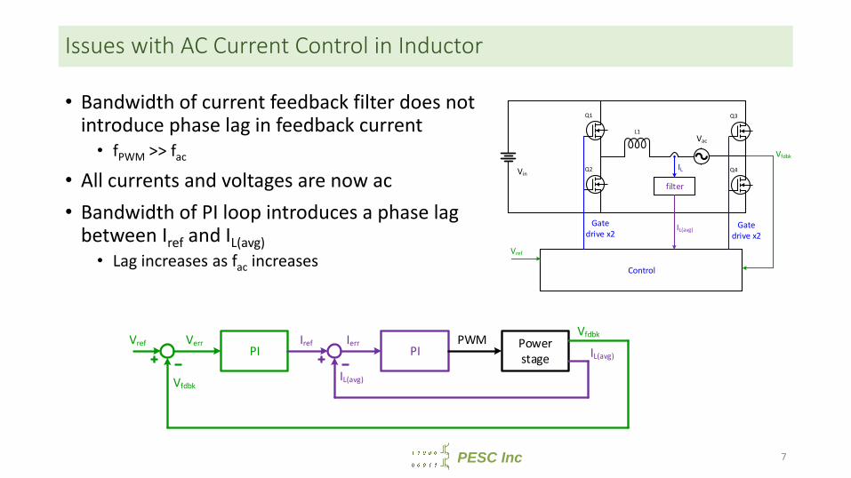
Issues with AC Current Control in Inductor
• Bandwidth of current feedback filter does not introduce phase lag in feedback current• fPWM >> fac
• All currents and voltages are now ac• Bandwidth of PI loop introduces a phase lag
between Iref and IL(avg)• Lag increases as fac increases
L1
Q1
Control
VinIL
Gate drive x2
filter
IL(avg)
Vfdbk
Vref
Q2
Q3
Q4
Gate drive x2
Vac
PI PI Power stage
PWMVref
Vfdbk
Verr Iref
IL(avg)
VfdbkIerrIL(avg)
7
PESC Inc
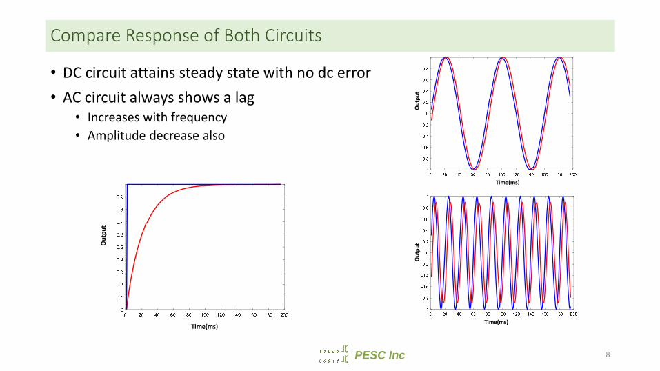
Compare Response of Both Circuits
• DC circuit attains steady state with no dc error• AC circuit always shows a lag
• Increases with frequency• Amplitude decrease also
Time(ms)
Outp
ut
Time(ms)
Outp
ut
Time(ms)
Outp
ut
8
PESC Inc
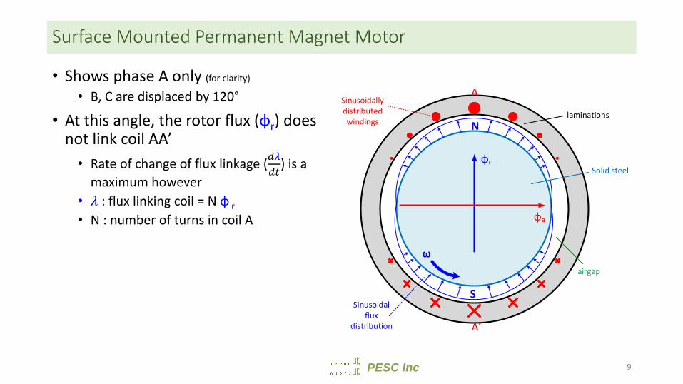
Surface Mounted Permanent Magnet Motor
• Shows phase A only (for clarity)
• B, C are displaced by 120°
• At this angle, the rotor flux (φr) does not link coil AA’• Rate of change of flux linkage ( ) is a
maximum however• : flux linking coil = N φ r• N : number of turns in coil A
9
N
S
laminations
Solid steel
airgap
A
A’
φr
φa
ω
Sinusoidally distributed windings
Sinusoidal flux
distribution
PESC Inc
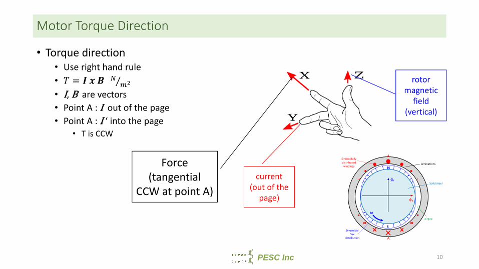
Motor Torque Direction
• Torque direction• Use right hand rule• = ⁄• I, B are vectors• Point A : I out of the page• Point A : I ‘ into the page
• T is CCW
10
current (out of the
page)
rotor magnetic
field (vertical)
Force(tangential
CCW at point A)
N
S
laminations
Solid steel
airgap
A
A’
φr
φa
ω
Sinusoidally distributed windings
Sinusoidal flux
distribution
PESC Inc
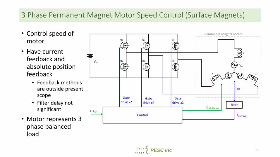
3 Phase Permanent Magnet Motor Speed Control (Surface Magnets)
• Control speed of motor
• Have current feedback and absolute position feedback• Feedback methods
are outside present scope
• Filter delay not significant
• Motor represents 3 phase balanced load
Q1
Control
Vin
Gate drive x2
θfdbk(abs)Ꙍref
Q2
Q5
Q6
Gate drive x2
Vac
L
Q3
Q4
Iabc
filter
Iabc(avg)
Gate drive x2
Permanent Magnet Motor
11
PESC Inc
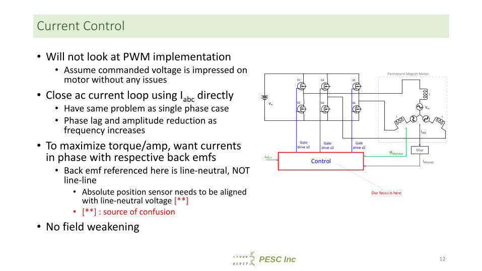
Current Control
• Will not look at PWM implementation• Assume commanded voltage is impressed on
motor without any issues• Close ac current loop using Iabc directly
• Have same problem as single phase case• Phase lag and amplitude reduction as
frequency increases• To maximize torque/amp, want currents
in phase with respective back emfs• Back emf referenced here is line-neutral, NOT
line-line• Absolute position sensor needs to be aligned
with line-neutral voltage [**]• [**] : source of confusion
• No field weakening
Q1
Control
Vin
Gate drive x2
θfdbk(abs)Ꙍref
Q2
Q5
Q6
Gate drive x2
Vac
L
Q3
Q4
Iabc
filter
Iabc(avg)
Gate drive x2
Permanent Magnet Motor
Our focus is here
12
PESC Inc
Agenda
• 1. Control of DC current• 2. Control of AC current (no DQ used)• 3. Motivation for DQ current control in 3 phase systems• 4. DQ Motor Model and speed control• 5. Issues with DQ control• 6. Induction Motor
13
PESC Inc
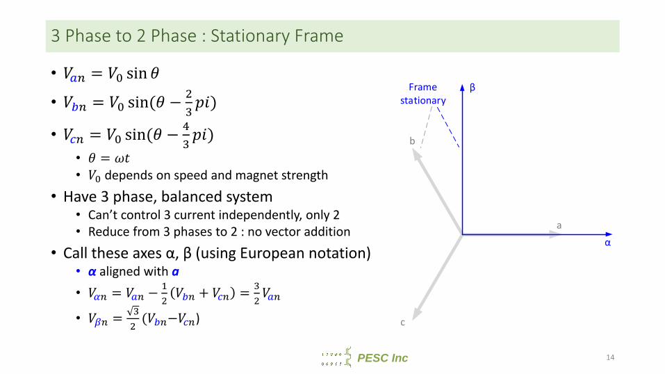
3 Phase to 2 Phase : Stationary Frame
• = sin• = sin( − )• = sin( − )
• =• depends on speed and magnet strength
• Have 3 phase, balanced system• Can’t control 3 current independently, only 2• Reduce from 3 phases to 2 : no vector addition
• Call these axes α, β (using European notation)• α aligned with a• = − + =• = ( − )
a
b
c
α
β Frame stationary
14
PESC Inc
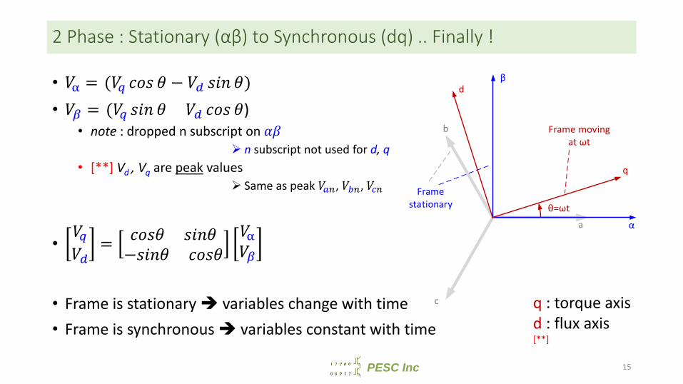
2 Phase : Stationary (αβ) to Synchronous (dq) .. Finally !
• = ( − )• = ( )
• note : dropped n subscript on n subscript not used for d, q
• [**] Vd , Vq are peak values Same as peak , ,
• = − • Frame is stationary variables change with time• Frame is synchronous variables constant with time
q : torque axisd : flux axis[**]
a
b
c
α
β
q
d
θ=ωt
Frame moving at ωt
Frame stationary
15
PESC Inc
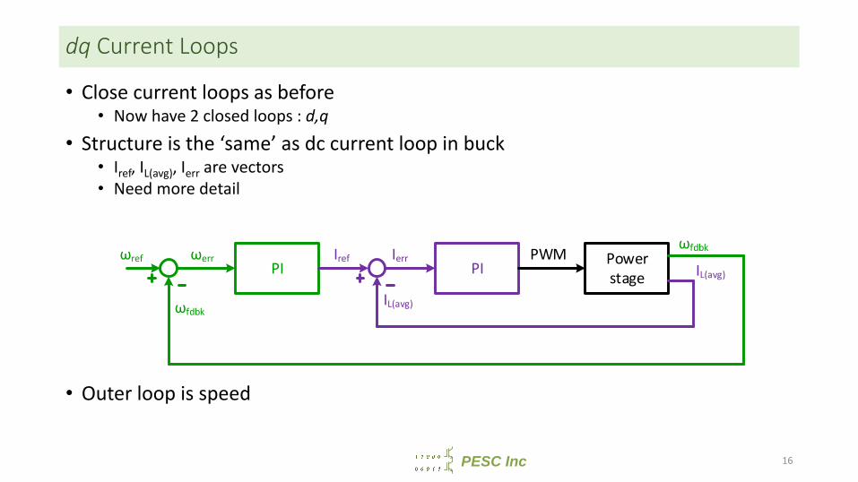
dq Current Loops
• Close current loops as before• Now have 2 closed loops : d,q
• Structure is the ‘same’ as dc current loop in buck• Iref, IL(avg), Ierr are vectors• Need more detail
• Outer loop is speed
PI PI Power stage
PWMωref
ωfdbk
ωerr Iref
IL(avg)
ωfdbkIerrIL(avg)
16
PESC Inc
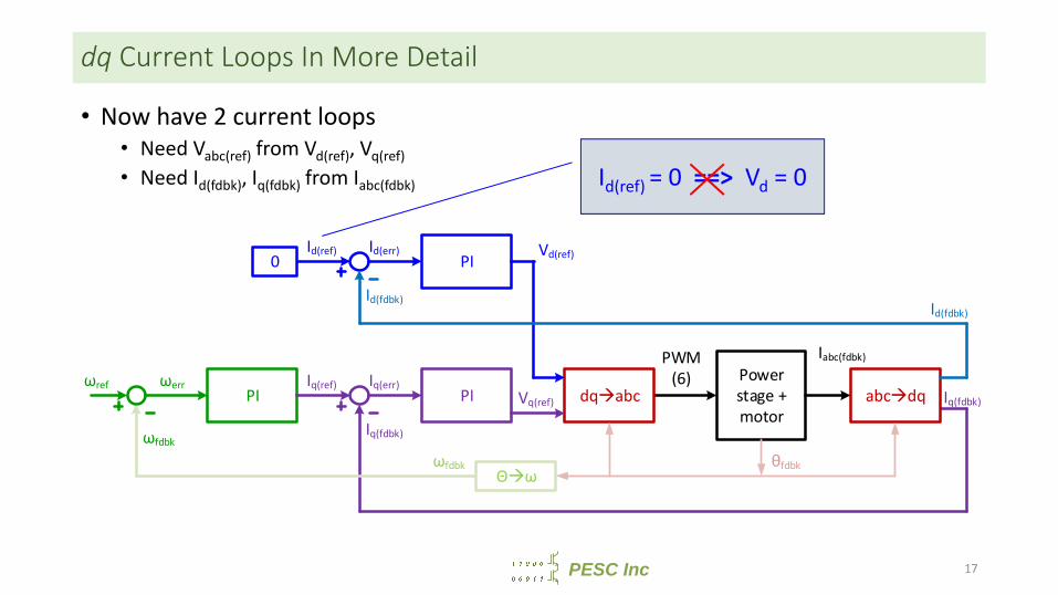
dq Current Loops In More Detail
• Now have 2 current loops• Need Vabc(ref) from Vd(ref), Vq(ref)• Need Id(fdbk), Iq(fdbk) from Iabc(fdbk)
PI PIPower stage + motor
PWM(6)ωref
ωfdbk
ωerr Iq(ref)
Iq(fdbk)
ωfdbk
Iq(err)Iq(fdbk)
PIId(ref)
Id(fdbk)
Id(err)0
dqabcVq(ref)
Vd(ref)
θfdbk
abcdq
Iabc(fdbk)
Id(fdbk)
Θω
Id(ref) = 0 ==> Vd = 0
17
PESC Inc
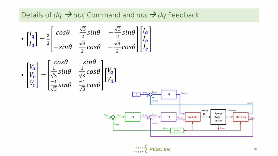
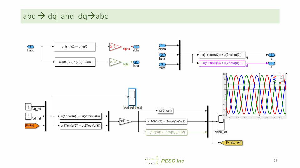
Details of dq abc Command and abc dq Feedback
• = −− −• =
PI PIPower stage + motor
PWM(6)ωref
ωfdbk
ωerr Iq(ref)
Iq(fdbk)
ωfdbk
Iq(err)Iq(fdbk)
PIId(ref)
Id(fdbk)
Id(err)0
dqabcVq(ref)
Vd(ref)
θfdbk
abcdq
Iabc(fdbk)
Id(fdbk)
Θω
18
PESC Inc
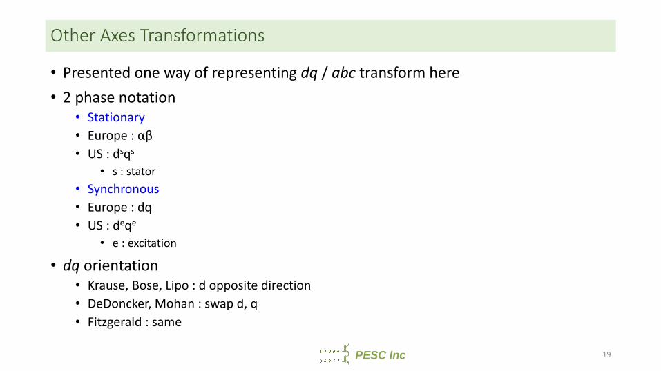
Other Axes Transformations
• Presented one way of representing dq / abc transform here• 2 phase notation
• Stationary• Europe : αβ• US : dsqs
• s : stator• Synchronous• Europe : dq• US : deqe
• e : excitation
• dq orientation• Krause, Bose, Lipo : d opposite direction• DeDoncker, Mohan : swap d, q• Fitzgerald : same
19
PESC Inc
Agenda
• 1. Control of DC current• 2. Control of AC current (no DQ used)• 3. Motivation for DQ current control in 3 phase systems• 4. DQ Motor Model and speed control• 5. Issues with DQ control• 6. Induction Motor
20
PESC Inc
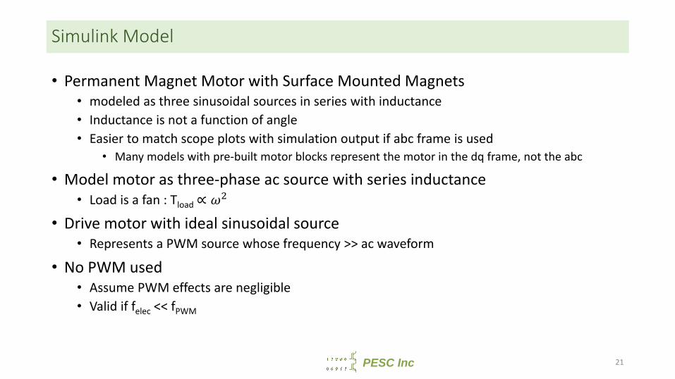
Simulink Model
• Permanent Magnet Motor with Surface Mounted Magnets• modeled as three sinusoidal sources in series with inductance• Inductance is not a function of angle• Easier to match scope plots with simulation output if abc frame is used
• Many models with pre-built motor blocks represent the motor in the dq frame, not the abc
• Model motor as three-phase ac source with series inductance• Load is a fan : Tload ∝
• Drive motor with ideal sinusoidal source• Represents a PWM source whose frequency >> ac waveform
• No PWM used• Assume PWM effects are negligible• Valid if felec << fPWM
21
PESC Inc
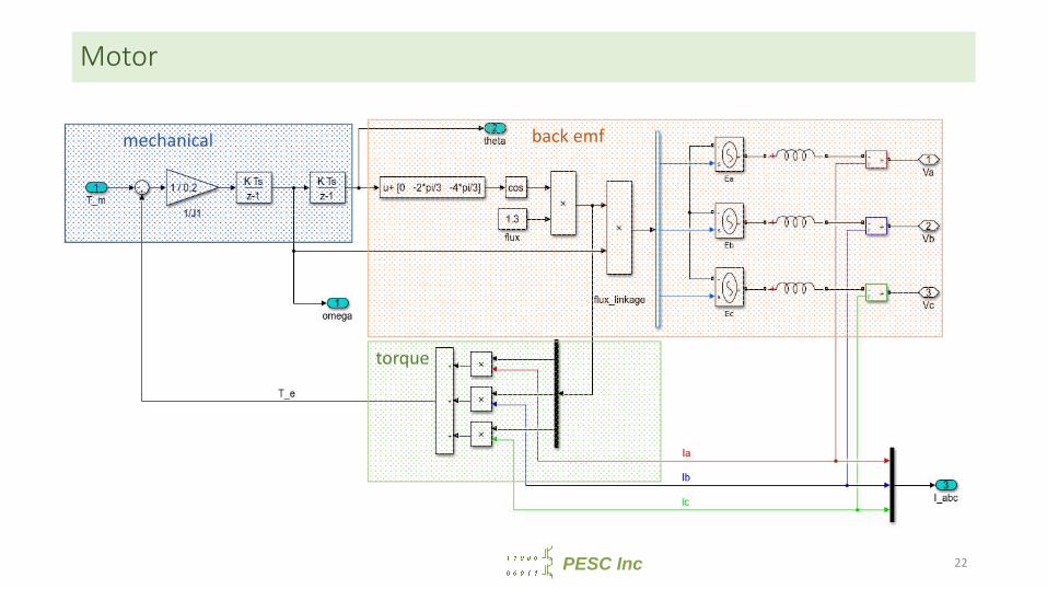
Motor
mechanical back emf
torque
22
PESC Inc
abc dq and dqabc
23
PESC Inc
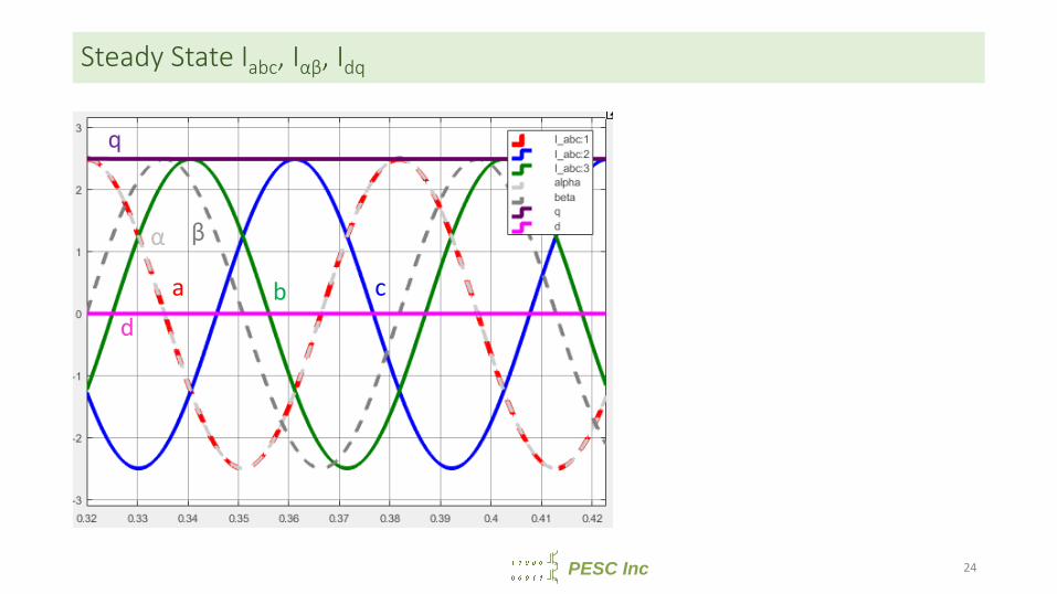
Steady State Iabc, Iαβ, Idq
q
da b c
βα
24
PESC Inc
Agenda
• 1. Control of DC current• 2. Control of AC current (no DQ used)• 3. Motivation for DQ current control in 3 phase systems• 4. DQ Motor Model and speed control• 5. Issues with DQ control• 6. Induction Motor
25
PESC Inc
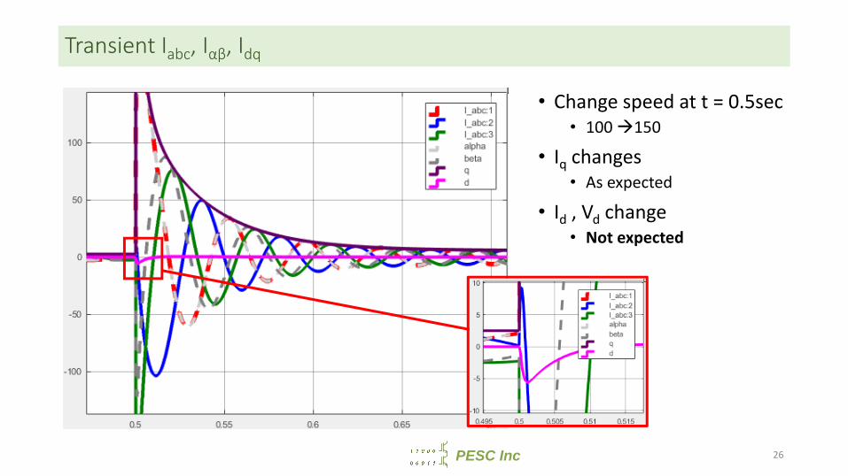
Transient Iabc, Iαβ, Idq
• Change speed at t = 0.5sec• 100 150
• Iq changes• As expected
• Id , Vd change• Not expected
26
PESC Inc
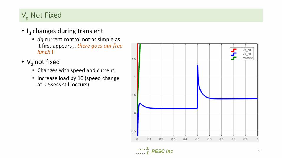
Vd Not Fixed
• Id changes during transient• dq current control not as simple as
it first appears .. there goes our free lunch !
• Vd not fixed• Changes with speed and current• Increase load by 10 (speed change
at 0.5secs still occurs)
27

PESC Inc
Agenda
• 1. Control of DC current• 2. Control of AC current (no DQ used)• 3. Motivation for DQ current control in 3 phase systems• 4. DQ Motor Model and speed control• 5. Issues with DQ control• 6. Induction Motor
28
PESC Inc
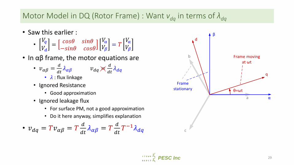
Motor Model in DQ (Rotor Frame) : Want vdq in terms of λdq
• Saw this earlier :• = − =
• In αβ frame, the motor equations are• = =
• : flux linkage• Ignored Resistance
• Good approximation• Ignored leakage flux
• For surface PM, not a good approximation• Do it here anyway, simplifies explanation
• = = =a
b
c
α
β
q
d
θ=ωt
Frame moving at ωt
Frame stationary
29
PESC Inc
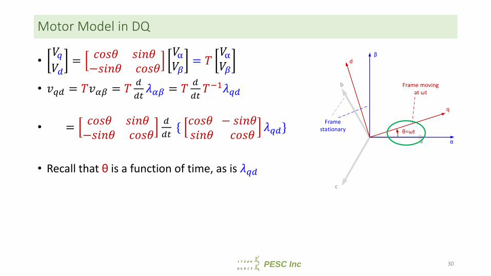
Motor Model in DQ
• = − =• = = =• = − { − }• Recall that θ is a function of time, as is
a
b
c
α
β
q
d
θ=ωt
Frame moving at ωt
Frame stationary
30
PESC Inc
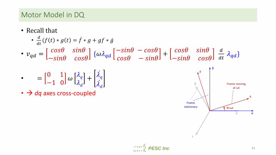
Motor Model in DQ
• Recall that• ( ∗ = ∗ + ∗
• = − { − − − + − }• = 0 1−1 0 +• dq axes cross-coupled
31
a
b
c
α
β
q
d
θ=ωt
Frame moving at ωt
Frame stationary
PESC Inc
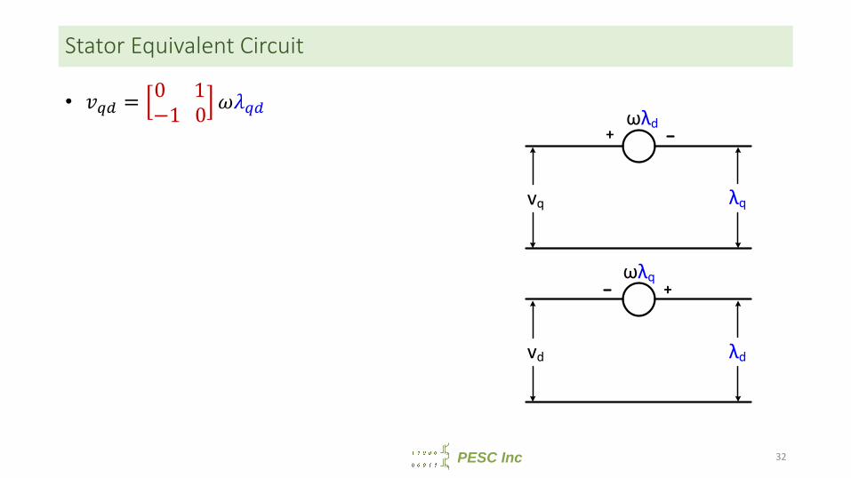
Stator Equivalent Circuit
• = 0 1−1 0
32
+
+
λq
ωλd
vd
vq
λd
ωλq
PESC Inc
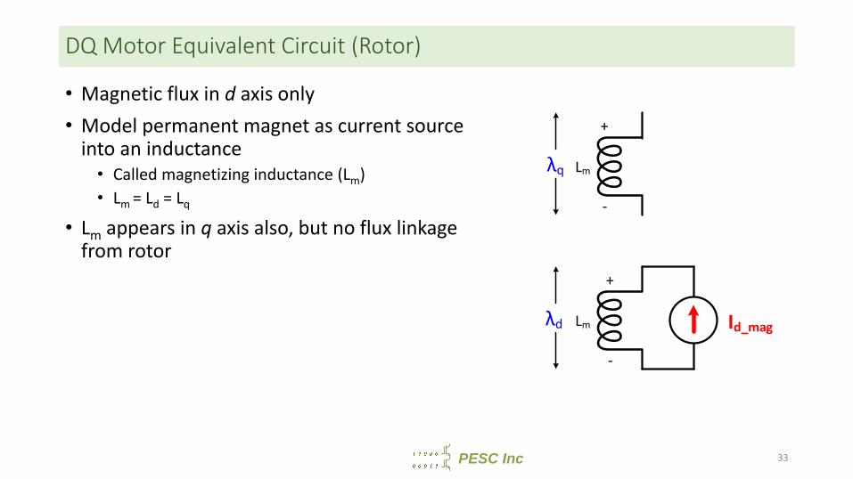
DQ Motor Equivalent Circuit (Rotor)
• Magnetic flux in d axis only• Model permanent magnet as current source
into an inductance• Called magnetizing inductance (Lm)• Lm = Ld = Lq
• Lm appears in q axis also, but no flux linkage from rotor
33
Lm Id_mag
Lm
+
-
+
-
λq
λd
PESC Inc
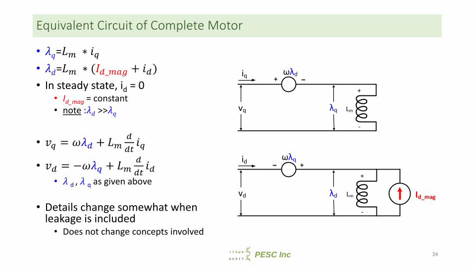
Equivalent Circuit of Complete Motor
• = ∗• = ∗ ( _ + )• In steady state, id = 0
• Id_mag = constant• note : >>
• = +• = − +
• d , q as given above
• Details change somewhat when leakage is included• Does not change concepts involved
34
Lm Id_mag
Lm
+
-
+
-
+
+
λq
ωλd
vd
vq
λd
ωλq
iq
id
PESC Inc
Agenda
• 1. Control of DC current• 2. Control of AC current (no DQ used)• 3. Motivation for DQ current control in 3 phase systems• 4. DQ Motor Model and speed control• 5. Issues with DQ control• 6. Induction Motor
35
PESC Inc
Induction Motor
• Rotor field is induced• Rotor consists of shorted bars (i.e. ends of bars are shorted)• No magnet to produce it
• Stator must produce Iq (torque) and Id(flux)• Still need Iq in phase with back emf
• Id is not fixed, as it is for the PM• Dynamics are more complex
• PM doesn’t have any rotor current• IM has to have Idr, or there will be no flux• Adds complexity in equivalent circuit
• Same concepts of axes cross-coupling exists• Need to know rotor position only for dq abc and for abc dq
• Derive rotor speed from position• “Analysis of Electric Machinery”, Krause .. Good reference
36
PESC Inc
Induction Motor
• Induction motor airgap << PM airgap• Permeability of magnets close to unity
• Induction motor Lm >> PM Lm• Easy to field weaken IM• Tough to field weaken PM
• IM and PM are non-salient rotors• Ld = Lq
• IM has 4 current components in qd reference frame• Stator : Iqs, Ids• Rotor : Iqr, Iqr
• PM dq transformation uses rotor frame• IM dq transformation can be excitation frame or rotor frame
• Excitation frame is synchronous ; rotor frame has slip is not synchronous
37
PESC Inc
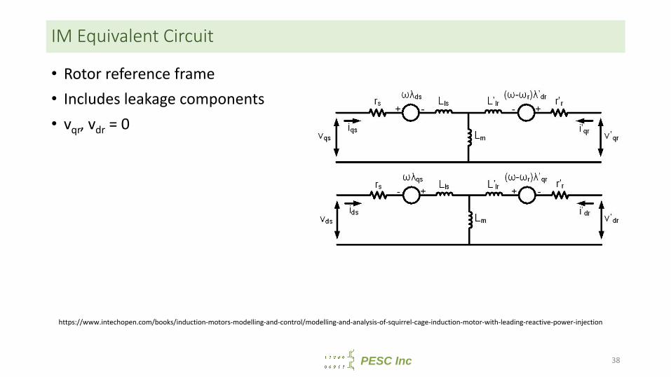
IM Equivalent Circuit
• Rotor reference frame• Includes leakage components• vqr, vdr = 0
https://www.intechopen.com/books/induction-motors-modelling-and-control/modelling-and-analysis-of-squirrel-cage-induction-motor-with-leading-reactive-power-injection
38