Embed Size (px)
Citation preview

Northwestern Formula SAE 2014-2015
Wheel Centers Design Documentation
Derek Oung and Patrick Peng

Terminology
Figure 1: Figure illustrating wheel center terminology and what they refer to

Goals
The wheel center is connected to the hub on the inboard side of the car and the rim on the outboard
side of the car. It transmits the loads from the car through the hub to the wheels through its
attachment to the rim and vice versa, allowing the car to accelerate, brake and turn.
Clearance: The wheel centers interface with the hub via dowel pins and with the rim via bolts. There can be no
geometrical interference between the wheel centers and any other component on the car, mainly the
brake calipers, uprights, hubs and brake rotors, at any orientation that the wheel center is designed to
be in. The hub and the rim are the two closest components and clearance between them and the
wheel centers has to be ensured.
Withstand load cases: The load cases include acceleration, braking and cornering. With acceleration and braking, we assume
1.6 g. The coefficient of friction used is 1.6.
Acceleration and Braking:
Maximum downward force on one wheel center is 240 lbf. Maximum total friction force is 384 lbf.
This load case is illustrated in Figure 3.
Cornering:
Maximum downward force on one wheel center is 279.5 lbf. Maximum lateral friction force is 440 lbf.
This load case is illustrated in Figure 5.
With the downward force from acceleration and braking as well as the downward force and lateral
friction force from cornering, there are moments that are induced on the wheel centers in addition to
forces. These moments are illustrated in Figure 4.
Figure 2: Exploded View of Corner Assembly

Figure 3: Load case for braking and acceleration
Figure 4: Figure illustrating the moment caused by cornering (left) and acceleration/braking (right)
loads that act on the tire contact patch

Figure 5: Load Case for Cornering
In Figure 5, d1 is the horizontal distance from the tire contact patch to the outboard surface of the
wheel center.
As a result of the downward forces from acceleration, braking and cornering acting on distance d1
from the wheel center, moments act on the wheel center and have to be accounted for.
d2 is the vertical distance from the tire contact patch to the center of the wheel center.
As a result of the lateral friction force from cornering acting on distance d2 from the wheel center, a
moment acts on the wheel center and have to be accounted for.
von Mises Stress:
The wheel centers have to be able to withstand the stresses introduced by the three load cases with a
designated factor of safety with respect to a fatigue stress. Using an experimental fatigue curve as
shown in Figure 12, the fatigue stress is determined by the number of load cycles the wheel center is
designed to go through. Our wheel centers were designed for 500 hours on track conditions.
Deformation:
As the wheel centers experience any of the three different load cases, they will undergo deformations
corresponding to each load case. These deformations should not exceed a designated displacement
because the wheel centers may not perform as expected if its geometry is altered too significantly.
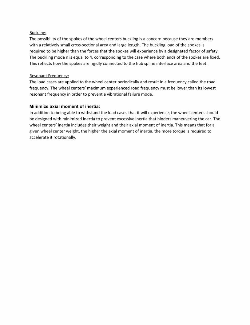
Buckling:
The possibility of the spokes of the wheel centers buckling is a concern because they are members
with a relatively small cross-sectional area and large length. The buckling load of the spokes is
required to be higher than the forces that the spokes will experience by a designated factor of safety.
The buckling mode n is equal to 4, corresponding to the case where both ends of the spokes are fixed.
This reflects how the spokes are rigidly connected to the hub spline interface area and the feet.
Resonant Frequency:
The load cases are applied to the wheel center periodically and result in a frequency called the road
frequency. The wheel centers’ maximum experienced road frequency must be lower than its lowest
resonant frequency in order to prevent a vibrational failure mode.
Minimize axial moment of inertia: In addition to being able to withstand the load cases that it will experience, the wheel centers should
be designed with minimized inertia to prevent excessive inertia that hinders maneuvering the car. The
wheel centers’ inertia includes their weight and their axial moment of inertia. This means that for a
given wheel center weight, the higher the axial moment of inertia, the more torque is required to
accelerate it rotationally.
Design
Constraints:
Pin Hole Positions:
This includes the pin circle diameter and the locations of the pin holes around this circle.
The pin circle diameter is the diameter of the circle of pin holes. Pin placed in these pin holes are used
to connect the wheel center to the hubs. The pin circles on the wheel center and the pin circles on the
hub have to align. Since the hub and the wheel center are designed jointly by the team, the analysis
and decision of where the pin holes are located were made jointly with the team. How this is
determined is covered under Pin Positions and Dimensions.
Hub Spline Interface Diameter:
The hub spline interface is the area on the inboard side of the wheel center that interfaces with the
spline geometry on the hub. The diameter of this area should ideally mirror the hub spline geometry
for maximum contact area between the wheel center and the hub while minimizing weight without
having excess non-contact area. The minimum hub spline interface diameter is constrained by the
tulip geometry that interfaces with the drive shaft. This is shown in Figure 6.
Bolt Hole Positions:
This includes the bolt circle diameter and the locations of the bolt holes around this circle.
The bolt circle diameter is the diameter of the circle of bolt hole. The bolt circle diameter on the
wheel center is determined by the bolt circle diameter on the rims. Cap screws placed through these
bolt holes are used to connect the wheel center and the rim and hence the bolts holes on the wheel
center and those on the rim have to align. Since, the rims are not designed by the team, the bolt hole
positions are fixed by the rim manufacturer.
Total Wheel Center Diameter:
The rims limit the maximum diameter due to a fillet on the circumference of the rim. The wheel
center diameter cannot exceed where this fillet starts due to interference.
Materials: Pins:
The pins are made of 416 Stainless Steel. This material is chosen because of its strength.
Modulus of Elasticity 29, 00 ksiE = = 0
ield strength 84, 00 psiY s = Y = 8
density 0.282 lb/inρ = = 3

Wheel Center:
The wheel center is made of Aluminum 7075-T7351. This material is chosen because of its good
strength to weight ratio. Its properties that are relevant are listed below.
Modulus of Elasticity 10400 ksiE = =
ield strength 63100 psiY s = Y =
density 0.102 lb/inρ = = 3
Factor of Safety:
We define our factor of safety as shown below.
OS F = Fatigue StressMaximum Experienced Stress
We obtained our fatigue stress by finding the corresponding number of load cycles we want our
wheel centers to reach under track conditions. We designed our wheel centers to withstand a desired
number of hours at an assumed average speed under track conditions.
We used the length of the Formula SAE: Michigan Endurance and Autocross tracks and estimated the
number of corners, accelerations and brakings required in each track. We assumed an average speed
of 41.16 mph and 35.53 mph for the endurance and autocross tracks respectively. These speeds
correspond to the best times in the 2014 events. Lastly, we chose to design our wheel centers to
withstand 500 hours under these conditions.
The resulting number of load cycles is 842,900 cycles. Using a fatigue curve for Aluminum 7075-T6 and
416 Stainless Steel, their fatigue stresses are 29,000 psi and 27,000 psi respectively.
More details regarding how the number of load cycles are found is in Table 4 in the Appendix.
Number of Bolts: The options for the number of bolts were 10 or 15. 15 is the maximum number of bolts holes on the
rim whereas 10 would allow weight savings on the wheel center. Performing a finite elements analysis
using Hypermesh, Nastran and Femap, we recovered the bolt forces in both scenarios using a wheel
center blank that assumes a stepped cylindrical shape of 1.25 in thickness from the middle up until
the feet where the bolt holes are, where the thickness is 0.3125 in instead. In the analysis, the bolts
are constrained, forces from the weight shift are applied radially inward and a torque due to
acceleration is applied over the pins. The recovered constraint forces are the bolt forces that we were
looking for. With 15 bolts, the resulting force on each bolt is about 40 lbf. With 10 bolts, the resulting
force on each bolt is about 60 lbf. These forces are well below what the bolts can handle and thus the
difference between the bolt forces were negligible. We decided to use a 10-bolt wheel center for the
weight savings. The results of the finite element analysis for both cases are shown in Figures 11 and
12 as well as Tables 5 and 6 in the appendix.
Number of Pins: The number of pins does not affect the amount of material required to withstand the torque that the
wheel center experiences from braking or accelerating. Because given a pin circle diameter, the

cross-sectional area of pins required to withstand the torque is constant. In other words, either a few
large pins are required or many small pins.
The deciding factor for the number of pins is that the number of pins should be a factor of the number
of bolts. This is because we want the loads to be split evenly between the pins and between the bolts.
We decided to use 5 pins instead of 10 because the spline geometry requires only 5 splines
corresponding to 5 pin holes instead of 10, which reduces weight on the hub.
Figure 6: Figure showing how the Tulip Geometry constrains the minimum spline interface diameter
on the hub and the minimum hub spline interface area on the wheel center
Pin Positions and Dimensions:
An iterative procedure was used in order to determine a minimum pin circle diameter. The smaller
the pin circle diameter, the smaller the hub spline interface area of the wheel center needs to be.
Since this is where most of the mass of the wheel center is, reducing this area not only reduces the
mass of the wheel center, but reduces the axial moment of inertia of the wheel center by having the
mass concentrated in the middle instead of closer to the circumference, as is the case with a large hub
spline interface area.
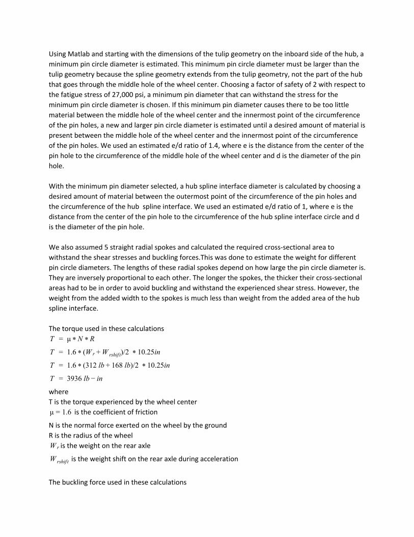
Using Matlab and starting with the dimensions of the tulip geometry on the inboard side of the hub, a
minimum pin circle diameter is estimated. This minimum pin circle diameter must be larger than the
tulip geometry because the spline geometry extends from the tulip geometry, not the part of the hub
that goes through the middle hole of the wheel center. Choosing a factor of safety of 2 with respect to
the fatigue stress of 27,000 psi, a minimum pin diameter that can withstand the stress for the
minimum pin circle diameter is chosen. If this minimum pin diameter causes there to be too little
material between the middle hole of the wheel center and the innermost point of the circumference
of the pin holes, a new and larger pin circle diameter is estimated until a desired amount of material is
present between the middle hole of the wheel center and the innermost point of the circumference
of the pin holes. We used an estimated e/d ratio of 1.4, where e is the distance from the center of the
pin hole to the circumference of the middle hole of the wheel center and d is the diameter of the pin
hole.
With the minimum pin diameter selected, a hub spline interface diameter is calculated by choosing a
desired amount of material between the outermost point of the circumference of the pin holes and
the circumference of the hub spline interface. We used an estimated e/d ratio of 1, where e is the
distance from the center of the pin hole to the circumference of the hub spline interface circle and d
is the diameter of the pin hole.
We also assumed 5 straight radial spokes and calculated the required cross-sectional area to
withstand the shear stresses and buckling forces.This was done to estimate the weight for different
pin circle diameters. The lengths of these radial spokes depend on how large the pin circle diameter is.
They are inversely proportional to each other. The longer the spokes, the thicker their cross-sectional
areas had to be in order to avoid buckling and withstand the experienced shear stress. However, the
weight from the added width to the spokes is much less than weight from the added area of the hub
spline interface.
The torque used in these calculations
μT = * N * R
1.6 W )/2 0.25inT = * ( r +W rshif t * 1
1.6 312 lb 68 lb)/2 0.25inT = * ( + 1 * 1
3936 lb nT = − i
where
T is the torque experienced by the wheel center
is the coefficient of friction.6μ = 1
N is the normal force exerted on the wheel by the ground
R is the radius of the wheel
is the weight on the rear axleW r
is the weight shift on the rear axle during accelerationW rshif t
The buckling force used in these calculations

n /LF = * π2 * E * I 2
where
F is the buckling force
n = 4 is the buckling mode since both ends of the spokes are fixed
E = 10400 ksi is the modulus of elasticity of Aluminum 7075-T7351
I is the moment of inertia of the cross-sectional area
t is the thickness of of the spoke in the axial direction of the wheel center
The shear stress experienced by the spokes is estimated using the beam shear stress equation in these
calculations
τ = ItV Q
where
is the shear stress experienced by the spokesτ
V is the shear force
Q is the statical moment of area
I is the moment of inertia of the cross-sectional area
t is the thickness of the material perpendicular to the shear
The resulting pin circle diameter is 3.0625 in. The resulting pin diameter is 0.3125 in. The resulting hub
spline interface diameter is 3.625 in. Assuming straight, radial spokes, the resulting length of the
spokes is 3.0625in and the resulting minimum cross-sectional area of the spokes is 0.0138 square
inches.
Simulations: Constraints:
Constraints are placed on the cylindrical faces of the pin holes and the flat faces of the hub spline
interface and nut interface. The constraint on the pin holes restricts radial translation while the
constraints on the hub spline interface and nut interface restrict axial translation. These constraints
are shown in Figure 7.
Loads:
Rigid loads with rigid connections are used for the loads shown in Figures 3 and 5. These loads are
shown in Figure 8.

Figure 7: Constraints:
Cylindrical constraints (top)
Hub Spline Interface constraint (bottom left)
Nut Interface constraint (bottom right)

Figure 8: Remote Loads with Rigid Connections:
Braking/Acceleration Loading Conditions (Left)
Cornering Loading Conditions (Right)

Spoke Geometry: We considered two different types of spoke geometries. The first is a straight radial spoke design
similar to that of a common street car and the second is a cross spoke design. They are shown in
Figure 9.
Figure 9: Straight Radial Spoke Design (Left)
Cross Spoke Design (Right)
We adjusted the spoke widths in order to ensure the two designs we compared are at about the same
weight of 1.51 lb. The spoke width for the wheel center design with the straight radial spokes is 0.168
in while that with the cross spokes is 0.125 inches. We conducted stress and deformation simulations
using Solidworks in acceleration/braking and cornering load cases in order to determine which design
was better suited for our design goals. The results are shown in Table 1. The details of the simulations
are shown in Figures 18 to 21 in the appendix.
Both designs have a surface loft that decreases the spoke thickness (dimension of spokes into the
page) radially. The closer they are to the hub spline interface area, the thicker they are. Both designs
have spokes of uniform thicknesses.
The radial spoke design had cut-outs on the hub spline interface area while the cross spoke design
does not. This is because there is not enough room between spokes on the cross spoke design for the
cutouts to be made. This means that the cross spoke design has more weight in the center and a
higher axial moment of inertia.

Table 1: Results of Spoke Design Comparison
Radial Spokes (Spoke width = 0.168’’) Cross Spokes (Spoke width = 0.125’’)
Weight (lb) 1.51 1.51
Moment of Inertia (lb-in^2)
11.71 11.31
First Mode of Resonant Frequency (Hz)
58.29704 42.84114
Cornering Braking Cornering Braking
Max Static Stress (ksi)
19.6 34.84 35.07 17.15
Factor of Safety 1.48 0.83 0.83 1.69
Max Deformation (in)
0.0147 0.046 0.01787 0.003661
Frequency Analysis:
The First Modes of Resonant Frequency for the radial spoke design is 58.29704 Hz while that for the cross spoke design is 42.84114 Hz.
The road frequency is calculated below:
6.4 rotations/s 16.4 Hzhour60 miles * 1 hour
3600 seconds * 1 mile5280 f t * 1 f t
12 in * 20.5 π in*1 rotation = 1 =
Although the first mode of resonant frequency of the radial spoke design is higher than that of the
cross spoke design, because the road frequency is well below the first modes of frequency for either
design, both designs meet the requirements for their first mode of resonant frequency.
After considering the different advantages and disadvantages the two designs have, we chose to use
the cross-spoke design despite its poorer performance in terms of frequency and maximum static
stress in cornering. The cross spoke design has better performance in terms of maximum static stress
in braking, maximum deformation in cornering and braking. The deciding factor was the large
deformation experienced by the radial spoke design in braking/acceleration.

Final Design
Figure 10: Final Design of the Wheel Center

For the final design of the wheel center, the width of the spokes are changed to vary radially from the
cross spoke design used in the spoke geometry comparison.
The closer to the center, the wider the spokes are because they have to withstand larger shear
stresses close to the hub spline interface area. This distributes the weight to resist loading conditions
more efficiently and reduces the weight on the wheel center.
Using Solidworks finite element analysis, the final wheel center design performance is illustrated in
Table 2. The details of the finite element analysis for the final wheel center design is shown in Figures
22 and 23.
Table 2: Final Wheel Center Design Simulation Results
Cornering Braking
Max Static Stress (ksi) 23.95 9.14
Factor of Safety 1.21 3.17
Max Deformation (in) 0.017 0.00347
Comparison with Last year’s design:
Figure 11: 2014 Northwestern Formula Racing Wheel Center Design (Left)
2015 Northwestern Formula Racing Wheel Center Design (Right)
The results of the comparison is shown in Table 3. The 2015 wheel center design has more weight and
axial moment of inertia than the 2014 wheel center design. This is because the 2015 wheel center is
designed to withstand 5 times the hours under track conditions than the 2014 wheel center.

Table 3: Comparison of 2014 and 2015 Northwestern Formula Racing Wheel Center Design
2014 2015 Percent difference (%)
Weight lb)( 1.2153 1.4600 +20.1
Axial Moment of Inertia lb n )( − i 2
8.3173 9.7200 +16.9
Figure 12: Final Manufactured Wheel Centers

Appendix
Figure 13: Fatigue Curve for Aluminum 7075-T6
We used the lowest curve in order to be conservative since the aluminum we used is 7075-T7351, a
different aluminum than the one shown in Figure 13.
Figure 14: FSAE Michigan Autocross 2014 Map
Figure 15: FSAE Michigan Endurance 2014 Map

Table 4: Table of Calculations for Number of Load Cycles

Figure 16: Finite Element Analysis for stresses (lbf) in wheel center blank (235101 elements, 50811
nodes)
Figure 17: Finite Element Analysis for forces (lbf) in wheel center blank (235101 elements, 50811
nodes)

Table 5: Bolt Forces Output for 15 bolts
Table 6: Bolts Forces Output for 10 bolts
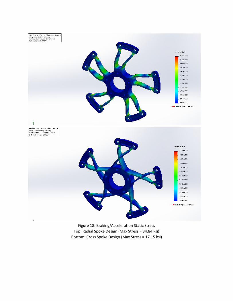
Figure 18: Braking/Acceleration Static Stress
Top: Radial Spoke Design (Max Stress = 34.84 ksi)
Bottom: Cross Spoke Design (Max Stress = 17.15 ksi)

Figure 19: Braking/Acceleration Deformation: (Deformation Scale = 59.2798)
Top: Radial Spoke Design (Max Deformation = 0.046 in)
Bottom: Cross Spoke Design (Max Deformation = 0.003661 in)

Figure 20: Cornering Static Stress:
Top: Radial Spoke Design (Max Stress = 19.6 ksi)
Bottom: Cross Spoke Design (Max Stress = 35.07 ksi)

Figure 21: Cornering Deformation: (Deformation Scale = 59.2798)
Top: Radial Spoke Design (Max Deformation = 0.0147 in)
Bottom: Cross Spoke Design (Max Deformation = 0.01787 in)

Figure 22: Braking/Acceleration Simulations for Final Wheel Center Design
Top: Static Stress (Max Stress = 9.14 ksi)
Bottom: Deformation (Deformation Scale = 59.2798, Max Deformation = 0.00347 in)

Figure 23: Cornering Simulations for Final Wheel Center Design
Top: Static Stress (Max Stress = 23.95 ksi)
Bottom: Deformation (Deformation Scale = 59.2798, Max Deformation = 0.017 in)