Embed Size (px)
Citation preview

BEST MANAGEMENT PRACTICES FOR
STORM WATER DISCHARGES ASSOCIATED
WITH CONSTRUCTION ACTIVITIES
Restoring, maintaining, and enhancing the quality of Oregon’s water.
Guidance for Eliminating or Reducing Pollutants in Storm Water Discharges
DEQ Northwest Region Document
February 2006

Best Management Practices for Storm Water Discharges Associated with Construction Activities
Background: In the last few years, more and more species of fish have been listed as threatened or endangered through the Endangered Species Act with the U.S. Environmental Protection Agency. Many individuals and groups have blamed these declines in fish population on various causes, like loss of habitat, dams, increased stream temperatures, industrial pollution, sedimentation of spawning beds, turbidity of streams, etc. The Oregon Department of Environmental Quality (DEQ) has determined that the BMPs contained in this document can, if used properly, make a positive impact on the health and welfare of fish and humans. Best Management Practices: BMPs are practices or procedures that include methods to prevent toxic
and hazardous substances and other pollutants from reaching receiving waters. They are designed to address the quality of a site’s practices with respect to storm water leaving the site, and may ultimately affect the ability of the site to meet environmental water quality standards or benchmarks. They are most effective when organized into a comprehensive Storm Water Erosion Control Plan. Many different practices can be used to achieve similar environmentally protective results. With site-specific or activity-specific considerations, such as the effect of the pollutant(s) of concern, as the major consideration(s) in selecting appropriate BMP’s, this flexibility allows a facility to tailor a Storm Water Erosion Control Plan to meet its needs using the capabilities and resources available.
The BMPs included in this document are to be considered a work-in-
progress and are by no means to be considered a complete list of appropriate erosion control measures. New technologies are continually being developed and refined. Additional BMPs will be added periodically to this document as they are found to be reliable and effective.
Best Usage: The best way to use this guide is to assess your site and your storm water discharge(s).
Determine the best BMPs for the site conditions that will have the most impact on the discharge(s). Select BMP(s) that will be most effective in controlling pollution in the storm water discharges for the resources and costs that will be required to implement those BMPs. Implement the BMPs selected and check the storm water discharges to verify the anticipated results of the BMP implementation and determine if more BMPs will be required in order to meet the benchmarks or water quality standards for the various pollutants of concern.
Caution: The efficiencies provided should be used as indicators of the potential effects the
implementation of any particular BMP may provide. The efficiencies can be variable depending on a number of factors including soil characteristics, flow, maintenance of BMP, loading, site slope and other factors.
Acknowledgments: Partial funding for the writing, initial publishing, and revision of this document
came from a Pollution Prevention Grant provided by EPA. This document was compiled by Carolyn Sharp and Dennis Jurries, Oregon DEQ.

Best Management Practices for Storm Water Discharges Associated with Construction Activities
Eugene Office 1102 Lincoln St., #210Eugene, OR 97401(541) 686-7838 or1-800-844-8467(541) 6867-5603 TTY(541) 686-7551 fax
Coos Bay Office 340 N Front St.Coos Bay, OR 97420(541) 269-2721(541) 269-7984 fax
Roseburg Office 725 SE MainRoseburg, OR 97470(541) 440-3338(541) 440-3396 fax
Medford Office 201 W Main St., #2-DMedford, OR 97501(541) 776-6010(541) 776-6105 TTY(541) 776-6262 fax
Bend Office 2146 NE 4th, #104Bend, OR 97701(541) 388-6146(541) 388-6145 TTY(541) 388-8283 fax
Pendleton Office 700 SE Emigrant, #330Pendleton, OR 97801(541) 276-4063, voiceand TTY(541) 278-0168 fax
Northwest Region 2020 SW 4th Ave., #400Portland, OR 97201(503) 229-5263(503) 229-6945 TTY(503) 229-6945 fax
Salem Office 750 Front St. NE, #120Salem, OR 97301(503) 378-8240 or1-800-349-7677(503) 378-3684 TTY(503) 373-7944 fax
NORTHWEST REGION EASTERN REGION (County) (County) Clatsop Washington Hood River Wheeler Columbia Multnomah Wasco Grant Tillamook Clackamas Sherman Baker Gilliam Deschutes WESTERN REGION Morrow Crook (County) Umatilla Klamath Yamhill Marion Union Lake Polk Linn Wallowa Harney Lincoln Clackamas Jefferson Malheur Lane Douglas Coos Curry Jackson Josephine
DEQ HEADQUARTERS 811 SW 6th Avenue
Portland, Oregon 97204 Toll-Free 1-800-452-4011
TTY (503) 229-6993

Best Management Practices for Storm Water Discharges Associated with Construction Activities
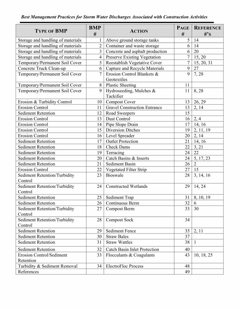
TYPE OF BMP BMP # ACTION PAGE
# REFERENCE
#’S Storage and handling of materials 1 Above ground storage tanks 5 14 Storage and handling of materials 2 Container and waste storage 6 14 Storage and handling of materials 3 Concrete and asphalt production 6 20 Storage and handling of materials 4 Preserve Existing Vegetation 7 15, 20 Temporary/Permanent Soil Cover 5 Reestablish Vegetative Cover 7 15, 20, 31 Concrete Truck Clean-up 6 Capture and Recycle Materials 9 27 Temporary/Permanent Soil Cover 7 Erosion Control Blankets &
Geotextiles 9 7, 28
Temporary/Permanent Soil Cover 8 Plastic Sheeting 11 Temporary/Permanent Soil Cover 9 Hydroseeding, Mulches &
Tackifier 11 8, 28
Erosion & Turbidity Control 10 Compost Cover 13 26, 29 Erosion Control 11 Gravel Construction Entrance 13 2, 14 Sediment Retention 12 Road Sweepers 15 Erosion Control 13 Dust Control 16 2, 4 Erosion Control 14 Pipe Slope Drain 17 14, 16 Erosion Control 15 Diversion Ditches 19 2, 11, 19 Erosion Control 16 Level Spreader 20 2, 14 Sediment Retention 17 Outlet Protection 21 14, 16 Sediment Retention 18 Check Dams 22 3, 21 Sediment Retention 19 Terracing 24 22 Sediment Retention 20 Catch Basins & Inserts 24 5, 17, 23 Sediment Retention 21 Sediment Basin 26 2 Erosion Control 22 Vegetated Filter Strip 27 15 Sediment Retention/Turbidity Control
23 Bioswale 28 3, 14, 16
Sediment Retention/Turbidity Control
24 Constructed Wetlands 29 14, 24
Sediment Retention 25 Sediment Trap 31 8, 10, 19 Sediment Retention 26 Continuous Berm 32 6 Sediment Retention/Turbidity Control
27 Compost Berm 33 30
Sediment Retention/Turbidity Control
28 Compost Sock 34
Sediment Retention 29 Sediment Fence 35 2, 11 Sediment Retention 30 Straw Bales 37 Sediment Retention 31 Straw Wattles 38 1 Sediment Retention 32 Catch Basin Inlet Protection 40 Erosion Control/Sediment Retention
33 Flocculants & Coagulants 43 10, 18, 25
Turbidity & Sediment Removal 34 ElectroFloc Process 48 References 49


Best Management Practices for Storm Water Discharges Associated with Construction Activities
Construction BMPs.doc Page 1 of 49
BEST MANAGEMENT PRACTICES FOR
STORM WATER DISCHARGES ASSOCIATED WITH CONSTRUCTION ACTIVITIES
INTRODUCTION
Best Management Practices (BMPs) are instrumental in developing the Erosion Control Plan (ECP) required by the National Pollutant Discharge Elimination System (NPDES) General Storm Water Discharge Permits. The NPDES program was established by federal legislation as part of the Clean Water Act to improve the quality of storm water from industries, or industrial type activities. Under this legislation, all point source discharges of pollutants, including those from construction sites, to federal waters (lakes, rivers, wetlands, etc.) must be authorized by a permit. Discharges to waters of the State may not contain pollutants or characteristics in levels that would cause the receiving water body to fail to meet water quality standards. Construction sites with one acre or more of disturbed soil must obtain a General Construction Storm water Discharge Permit. Rather than delineate particular practices that all sites should adhere to, the NPDES sets standards for minimum allowed pollution limits that allow the permittee to select technologies to meet those
standards. BMPs are measures or controls that reduce pollutants at the source to prevent the pollution of storm water runoff discharged from the site. These practices can also be used to divert runoff away from areas of exposure to pollutants, or to treat storm water runoff before discharge to receiving waters. In addition, BMPs can be used to direct polluted runoff to natural or other types of treatment. The storm water discharge permits do not require specific BMPs because the practices should be selected on a case-by-case basis depending on the particular conditions at the site. These factors include the quantity of rainfall reaching the site, the area of land available for constructing management practices, costs in
Examples of BMPs that can be used on a construction site
Best Management Practices for Storm Water Discharges Associated with Construction Activities
Construction BMPs.doc Page 2 of 49
implementing the practices, site slope, soil type, etc. . In selecting a BMP for the site's storm water erosion control program, the permittee should choose “source reduction” practices as much as practicable. These are practices that reduce the amount of erosion that is generated at the site and prevent contaminants from being exposed to storm water. If this is not possible, practices that recycle or reuse the runoff on the site should be considered. Treating contaminated storm water to remove pollutants before the runoff leaves the site is the last option. Source reduction methods are the most desirable BMPs because they keep storm water away from pollutants and are frequently less costly than treatment alternatives. There are a variety of mechanisms available for treating storm water. It should be noted that treatment mechanisms, in most cases, are not a substitute for the preventive BMPs. Storm water treatment mechanisms should be considered in instances where source reduction BMPs are not sufficient. STORM WATER BEST MANAGEMENT PRACTICES The BMPs included in this guidance document are related to source reduction and treatment methods for specific processes and activities ongoing at construction sites. The permittee should consider the recommended practices in developing and/or revising their Erosion Control Plan if these activities are ongoing at the facility. In addition, the preventive measures mentioned may assist the facility in achieving storm water discharge benchmarks and limitations or water quality standards through pollution prevention. All of the BMPs recommended in this guidance are intended to complement, not conflict with, existing state and federal regulations regarding the handling, containment, or treatment of any material or waste. The most effective BMP for preventing erosion is to not expose soil to storm water by removing existing vegetation any sooner than is absolutely necessary. Many contractors feel it is most cost effective to remove all of the vegetation and start grading the entire site due to the cost of set-up in bringing construction equipment to a site more than once. This in most cases is a false cost savings. The additional costs in erosion controls and treatment facilities to control erosion or turbid runoff from a site to meet State water quality standards and the fines for polluting in addition to possible negative publicity will be far more costly. Make sure controls are installed properly and able to handle expected volumes of water. If the BMP is not installed correctly, they will not serve their purpose and will allow sediment to runoff into waters of the State. Likewise, if the mechanism is overwhelmed with excessive amounts of water, sediments will be allowed to pass into the receiving waters. Use BMPs in conjunction with one another to complement and support each other. Pairing BMPs that prevent erosion with those that filter out sediments from runoff is a common and highly effective practice. Plan ahead for maintenance. Some controls are less weather and time resistant than others and will require replacement or repair. Regular maintenance must occur on most controls to remove

Best Management Practices for Storm Water Discharges Associated with Construction Activities
Construction BMPs.doc Page 3 of 49
accumulated sediments, which if left in place will reduce effectiveness. Flagged poles or stakes can be used to mark storm drains, catch basins, curb inlets, etc. This helps protect sediment controls from being hit by cars and street cleaners, buried under mounds of soil, or lost in fields of high grasses. Removal of temporary sediment and erosion control BMPs At the conclusion of the construction project after vegetation is reestablished, temporary erosion and sediment controls such as sediment fences, catch basin insert bags, and biobags should be removed from the construction site. Prior to their removal, the up-gradient sediment trapped by the erosion control should be removed by Vactor Truck, shovel, sweeping, etc. Failure to remove the retained sediment will result in a slug of sediment being released to the receiving stream and negate the reason for installing the controls in the first place. Considerations in selecting a BMP: Efficiency vs. Flow Volume – Typically, one is sacrificed for the other. The higher the flow volume, the less sediment and turbidity will be reduced. Time is needed to allow sediments to settle out of water. Finer filters trap more sediment, but water also takes longer to pass through, or more filtration surface area is needed to meet the increased need for flow volume. Initial and Life Cycle Costs –Some control mechanisms are expensive to install, but are low maintenance and long-lasting. Conversely, other BMPs are inexpensive to install but require frequent sediment removal or replacement. One must be aware of all the associated costs, from installation to maintenance and removal at job completion. Pollutants Involved – Different BMPs are designed to remove different pollutants. Some will remove heavy metals or oils and grease, while others are only effective for sediment and larger particles. BMPs that prevent erosion from occurring in the first place are generally more efficient than those that treat runoff that has already been infused with sediments. Oregon Water Quality Standards: Oregon Administrative Rule 340-041-0445 states “no more than a ten percent cumulative increase in natural stream turbidities shall be allowed, (may be changing in 2006) as measured relative to a control point immediately upstream of the turbidity causing activity. However, limited duration activities necessary to address an emergency or to accommodate essential dredging, construction, or other legitimate activities and which cause the standard to be exceeded may be authorized provided all practicable turbidity control techniques have been applied.” The following BMPs, when installed correctly and properly maintained will help reduce sediment and turbidity levels in runoff to acceptable levels.

Best Management Practices for Storm Water Discharges Associated with Construction Activities
Construction BMPs.doc Page 4 of 49
Erosion and Sediment Control Types of Erosion: Soil erosion is the process by which wind, ice, water and gravity wear away the land’s surface. Natural erosion and soil formation are part of the geologic processes that shape the face of the earth and keep soil thickness fairly constant. Events such as floods, earthquakes, construction and agriculture speed up erosion, leading to a soil deficit. The typical construction site produces 100-500 tons of erosion/acre/year, 100 times greater than croplands and 2000 times greater than the natural rate. Four major factors determine the potential for soil erosion: soil type, presence of vegetative cover, topography (steepness of slope) and climate. The loosened particles of soil are called sediment, and the deposition of this material in bodies of water is called sedimentation. Turbidity is the suspension of very light soil pr other fines in water. Sedimentation and turbidity associated with sediment-laden flows degrade water quality. Turbidity interferes with photosynthesis, encourages disease in fish and other aquatic life, interferes with fish breathing by clogging the gill passages, reduces the ability of fish to feed, and sediment settles in fish spawning beds smothering the eggs. Erosion also makes it more expensive to treat drinking water to acceptable standards, and increases the chances of floods by accumulating in and blocking culverts. Splash erosion, caused by the impact of rain hitting the ground, is the most destructive type of erosion. Raindrops impact the earth at 20 miles per hour, 10-100 times faster than sheet flow, dislodging soil particles. Sheet erosion is characterized by shallow, uniform water flows. Rill erosion occurs when water begins to concentrate in small channels and leads to gully erosion, larger and deeper rills. Channel erosion is a result of higher velocity and flows of water, and is not easily repaired. Over time, erosion control is more effective than sediment control in preventing water quality problems. Erosion control is less subject to failure from high flows, requires less maintenance, and is also less costly. In some cases a combination of erosion control and sediment control may be required. The following best management practices can be used for areas on construction sites with exposed soil from steep slopes, soil stockpiles, and/or heavy equipment traffic. Regular inspection and prompt maintenance are critical to the success of all the practices in this section. The selection of an appropriate measure will depend on the degree of slope on the site, sensitivity of the area to the intended use, stream

Best Management Practices for Storm Water Discharges Associated with Construction Activities
Construction BMPs.doc Page 5 of 49
or wetland features in the area, and type of soil encountered. BMP #1 - Above-ground Storage Tanks
Description:
Tanks used on construction sites to refuel construction vehicles need to have secondary containment. The tank shown on the left is held in place by earthen berms and is a single walled tank. Notice the darker stained soil in front of the tank. The hose needs to be inside of a contained area when not in use so that any residual fuel in the hose does not leak out into the soil and thus to storm water runoff. A containment pallet similar to the one shown on the right could provide the secondary containment needed. The amount of rainfall on the small surface area involved with the tank and pallet would not accumulate significant amounts of storm water to be of concern.
Maintenance: • Check containers daily for leaks and spills. Replace containers that are leaking, corroded, or
otherwise deteriorating. • Collect all spilled liquids and properly dispose of them. • Sweep and clean the storage area monthly if it is paved; never hose down the area to a storm drain.

Best Management Practices for Storm Water Discharges Associated with Construction Activities
Construction BMPs.doc Page 6 of 49
BMP #2 - Container and Waste Storage Description:
This BMP refers to containers located outdoors and used to temporarily store materials, such as accumulated food wastes, paints, oils, vegetable or animal grease, solvents, and waste materials. If the construction site has container storage of materials in an outdoor location, consider using a portable building such as is shown on the next page. These storage buildings have secondary containment, can be sprinklered, and heated or cooled to control the temperature of the materials. The doors typically can be locked for secure storage. The fuel tank from the previous BMP could be placed in one of these buildings.
Design Considerations: Segregate and securely store incompatible or reactive materials in separate containment areas in order to prevent the mixing of chemicals should spills occur.
Maintenance: • Sweep the area regularly, if paved, to collect dirt and debris; never use water to hose down the area
into a storm drain. BMP #3 - Concrete and Asphalt Production Description:
Asphalt application can contribute high levels of toxic hydrocarbons, oils and greases, and heavy metal to runoff. Concrete pouring can contribute suspended solids and heavy metals to storm water runoff and cause pH increases in receiving waters.
Basic Design and Construction: • Use drip pans, ground cloths and perhaps even heavy cardboard or plywood wherever concrete,
asphalt and asphalt emulsion chunks and drips are likely to fall, such as beneath extraction points from mixing equipment.
• Place storm drain covers over all nearby drains at the beginning of the workday. All accumulations must be collected with a shovel for proper disposal at the end of the workday.
• Contain and collect the slurry from exposed aggregate washing, where the top layer of unhardened concrete is hosed or scraped off to leave a rough finish. Use a cover to protect storm drains.
• Designate a washout area on-site where cleaning of concrete trucks, troughs, and pumps can take place and were the rinse water is controlled in an infiltration sump on-site.
• If possible, portable asphalt mixing equipment should be covered with an awning to avoid contact with rainfall.
• A catch basin insert configured for sediment removal may remove some of the pollutants in runoff from the site.

Best Management Practices for Storm Water Discharges Associated with Construction Activities
Construction BMPs.doc Page 7 of 49
Maintenance: • Sweep the pouring area, if it is paved, at the end of each day to collect loose aggregate particles. Do
not hose down the area to a storm drain. BMP #4 - Preserve Existing Vegetation Description:
Preserving the existing vegetation on a construction site is frequently the best preventative measure for erosion. Vegetation limits the capacity of flowing water to detach soil particles and transport sediment by decreasing runoff volume and the velocity of raindrops as they hit the ground. Because native or existing vegetation is already established, it is usually a better cover species than introduced species. They are adapted to local climate and soil conditions and typically have fewer pests, minimizing the amount of maintenance.
Basic Design and Construction: • All steep, unstable slopes should be left vegetated whenever possible. • Do not remove any vegetation unless absolutely necessary. • Mature trees, with their extensive root system and large canopy, serve important erosion control
functions and should be preserved when at all possible. • Compaction and grading of soils close to trees often will cause existing trees to decline and die.
Soil should not be piled on top of roots, cutting off air and suffocating the tree. Compaction results from parking and/or driving too close to the tree, restricting the movement of gases and water.
• Where possible, establish "do not disturb" zones on your site by marking off areas with stakes and tape or fencing materials.
• When lowering the grade of the site, terrace around the tree and the support the soil with a retaining wall so that tree roots are not exposed.
• Avoid cutting off the root system by tunneling under the roots rather than trenching through them. Maintenance: • Irrigation in dry months. • Monitor for the presence of pests or disease that will weaken the plant population. • Minimize the impact of construction activities on existing vegetation.
BMP #5 - Reestablish Vegetative Cover Description:
Vegetative cover acts as either a permanent cover or as a temporary measure prior to permanently stabilizing an area. Vegetation shields the soil from the direct impact of rainfall or runoff, increases soil porosity and water storage capacity of the soil, reduces the energy of the runoff, and physically holds the soil in place with the root system of the vegetation. Vegetative buffers or complete coverage can provide a significant reduction of erosion potential. This can be accomplished by seeding, seeding and mulching, seeding and matting, or sodding. Maintenance may be required to successfully vegetate an area. This practice is not suited for areas that carry heavy traffic.

Best Management Practices for Storm Water Discharges Associated with Construction Activities
Construction BMPs.doc Page 8 of 49
Basic Design and Construction: • Spread 4-6” of topsoil or compost over the site
before seeding or planting. • Fertilize according to soil test recommendations. • Mulch with straw or other matting. • Water as needed to keep soil moist. • Use seed mix recommendations from local
suppliers. Seed mixes should be based upon the time of year seeding is taking place. Use low maintenance, native grasses. If planting is done in July or August, irrigation will be necessary.
• Shrubs should be planted 2’-5’ apart; Trees 6’-10’ for wooded areas.
Design Considerations:
Mulching should be done in areas which cannot be seeded due to the season or other issues. They can also be applied to newly seeded areas to provide protection and cover until seed is established or to exposed soils that need immediate cover and protection. Suitable materials include straw, wood chips, corn stalks, and shredded bark. The material should be dry and free of weeds and seeds. In dry weather the mulch may need to be anchored with netting or a fiber and tackifier to prevent it from blowing away. All mulched areas should be checked periodically for spots where mulch has blown away or been pushed together.
Maintenance:
• Fertilize and water as recommended by supplier. • Re-seed areas where adequate cover has not been established.
Efficiency:
(After vegetation has had time to establish a root system) – 90% (EPA, 1999)
Minutes of simulated rainfall for 10% slope Rogers & Schumm 1991

Best Management Practices for Storm Water Discharges Associated with Construction Activities
Construction BMPs.doc Page 9 of 49
BMP #6 – Concrete Truck Washout and Cleanup
Description: Cleanup from the chute and other equipment from a concrete truck after emptying can cause high pH in storm water runoff and can fill catch basins and storm sewer piping with fine particles.
Best Management Practice: Until recently the only Best Management Practice was to select an area of the site for the washdown activities from concrete truck. This area would have a pit sized for the infiltration rate of the soil and the anticipated usage rate, in which the residual concrete, aggregate, and water would settle and infiltrate. Recycling System: A recycling system can be added to the concrete truck to catch the wash-down materials and pump them back into the truck for transport back to the concrete batch plant for recycling.
Efficiency: With care to prevent or minimize loss from carryover or splash-over, the use of a pit can neutralize the high pH with the low pH soil contact and virtually eliminate this particulate runoff issue connected with the practice at construction sites. The use of a pit usually entails moving the concrete truck to the pit location in order to clean out the chute. The added benefits gained from using the truck mounted recycling system are that the concrete trucks would not have to relocate from the pouring area to perform clean-up and the material washed off is recycled which is always a good environmental practice.
BMP #7 - Erosion Control Blankets & Geotextiles Description:
Rolled Erosion Control Products (netting, meshes, erosion control blankets, turf reinforcement mats)
Best Management Practices for Storm Water Discharges Associated with Construction Activities
Construction BMPs.doc Page 10 of 49
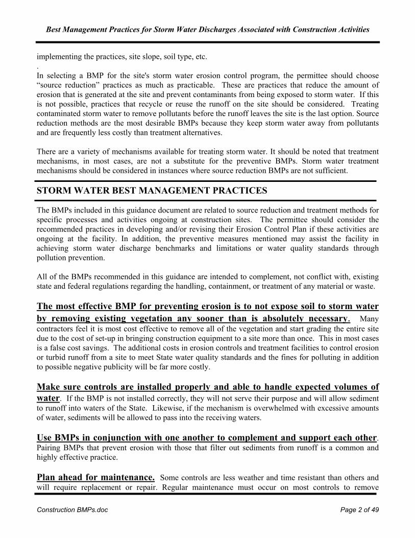
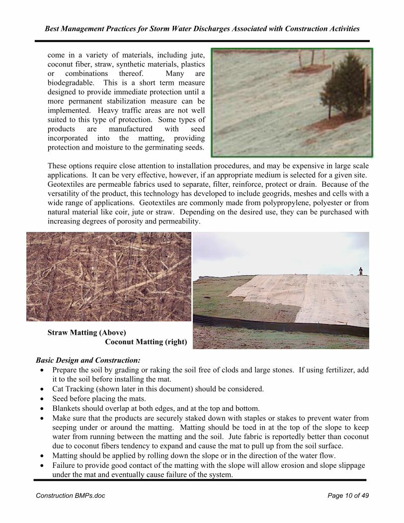
come in a variety of materials, including jute, coconut fiber, straw, synthetic materials, plastics or combinations thereof. Many are biodegradable. This is a short term measure designed to provide immediate protection until a more permanent stabilization measure can be implemented. Heavy traffic areas are not well suited to this type of protection. Some types of products are manufactured with seed incorporated into the matting, providing protection and moisture to the germinating seeds. These options require close attention to installation procedures, and may be expensive in large scale applications. It can be very effective, however, if an appropriate medium is selected for a given site. Geotextiles are permeable fabrics used to separate, filter, reinforce, protect or drain. Because of the versatility of the product, this technology has developed to include geogrids, meshes and cells with a wide range of applications. Geotextiles are commonly made from polypropylene, polyester or from natural material like coir, jute or straw. Depending on the desired use, they can be purchased with increasing degrees of porosity and permeability.
Straw Matting (Above) Coconut Matting (right)
Basic Design and Construction: • Prepare the soil by grading or raking the soil free of clods and large stones. If using fertilizer, add
it to the soil before installing the mat. • Cat Tracking (shown later in this document) should be considered. • Seed before placing the mats. • Blankets should overlap at both edges, and at the top and bottom. • Make sure that the products are securely staked down with staples or stakes to prevent water from
seeping under or around the matting. Matting should be toed in at the top of the slope to keep water from running between the matting and the soil. Jute fabric is reportedly better than coconut due to coconut fibers tendency to expand and cause the mat to pull up from the soil surface.
• Matting should be applied by rolling down the slope or in the direction of the water flow. • Failure to provide good contact of the matting with the slope will allow erosion and slope slippage
under the mat and eventually cause failure of the system.
Best Management Practices for Storm Water Discharges Associated with Construction Activities
Construction BMPs.doc Page 11 of 49
Design Considerations:
Where water infiltration is not desirable, for example on extremely unstable or steep slopes, an impermeable erosion blanket such as visqueen or other plastic material may be appropriate. In this situation, special care must be taken to provide a place where the energy the water has gained can dissipate, such as a slash windrow, brush sediment barrier, or rock blanket at the base of the slope and to provide a means to convey this clean water off the site without contacting the disturbed soil of the construction site. See the next BMP.
Maintenance: • Check regularly for rips or locations where the matting is no longer held in place. • Verify after storms that runoff has not seeped under the matting.
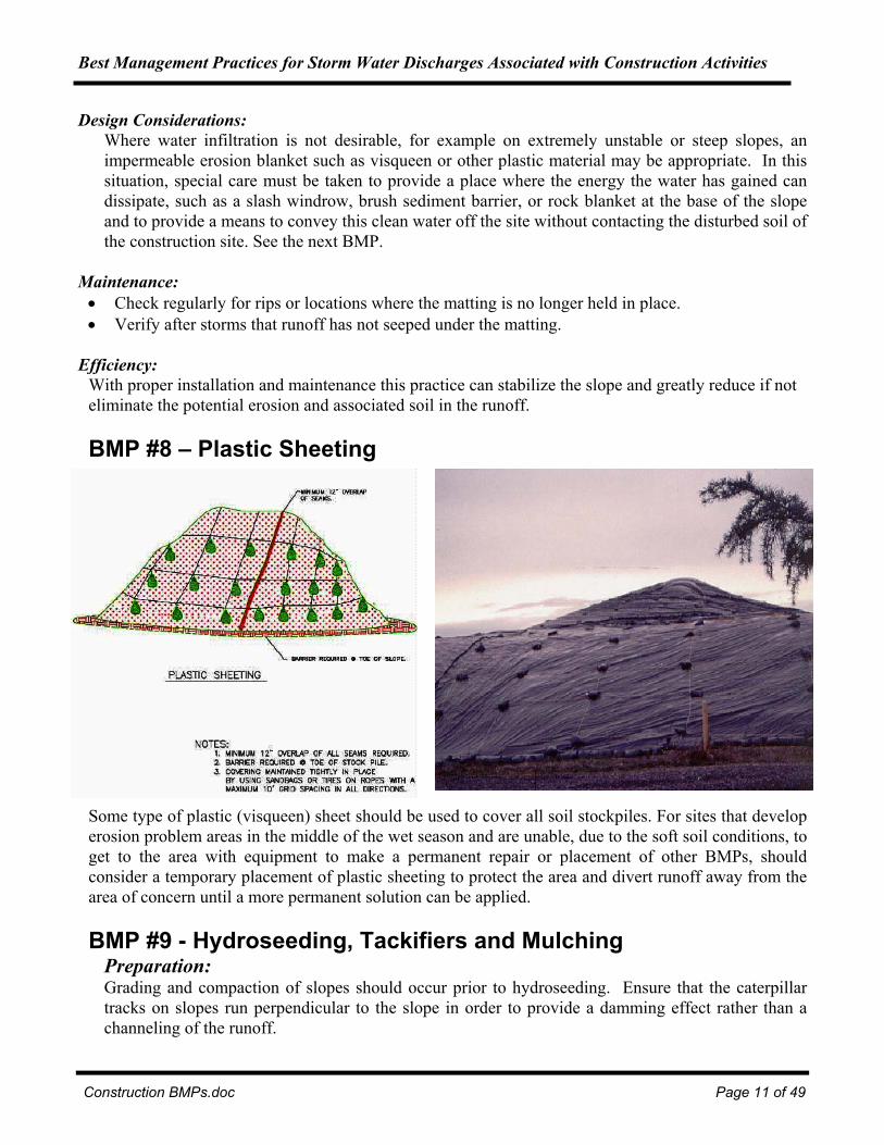
Efficiency: With proper installation and maintenance this practice can stabilize the slope and greatly reduce if not eliminate the potential erosion and associated soil in the runoff. BMP #8 – Plastic Sheeting
Some type of plastic (visqueen) sheet should be used to cover all soil stockpiles. For sites that develop erosion problem areas in the middle of the wet season and are unable, due to the soft soil conditions, to get to the area with equipment to make a permanent repair or placement of other BMPs, should consider a temporary placement of plastic sheeting to protect the area and divert runoff away from the area of concern until a more permanent solution can be applied. BMP #9 - Hydroseeding, Tackifiers and Mulching
Preparation: Grading and compaction of slopes should occur prior to hydroseeding. Ensure that the caterpillar tracks on slopes run perpendicular to the slope in order to provide a damming effect rather than a channeling of the runoff.

Best Management Practices for Storm Water Discharges Associated with Construction Activities
Construction BMPs.doc Page 12 of 49
Hydroseeding: Hydroseeding is the application of a mulch, seed and fertilizer slurry to establish vegetation and prevent erosion. This is a very economical option that stabilizes the slope until grasses and plants are able to sprout. Hydroseed provides water retention, soil retention, and protection for germinating seeds from sun and wind. A wide variety of seed mixes are commercially available to suit each site’s needs. The mulch can reduce the tendency of the seeds from washing away, depending on the type of mulch can retain up to 10 times its weight in water to keep the seeds moist, and adds nutrients to the soil as it decomposes. This is especially true if compost or bonded wood fiber is used with the seed mix. Mulching: This practice is the application of plant material such as compost, or straw to the soil surface, and can be used alone, or as part of a hydroseeding mixture as discussed above. It reduces erosion by shielding the soil from the force of raindrop impact and reducing the velocity of runoff flowing over the soil. Straw and mulch should be applied at the rate of at least 1 ½ -2 tons per acre, until the soil surface is not visible through the mulch. Mulch can also aid in seed growth by conserving moisture and shielding the young plants from extremes of heat, cold, or dry conditions. Mulch may need to be held in place by sprayed-on tackifiers or netting. Tackifiers: Tackifiers are a biodegradable adhesive that can be applied directly to the soil, or over a layer of mulch. It acts as a glue to hold the soil in place or increase the holding power of the mulch. One tackifier used by a local company is a vegetable based adhesive made of guar gum which the import from India. Coagulants and flocculants (polymers) can be used. An interesting product call DriWatertm actually releases water as it biodegrades which immediately brings to mind an advantage when hydroseeding in late summer. Tackifiers or netting are necessary in high or frequent wind areas to hold down straw.

Best Management Practices for Storm Water Discharges Associated with Construction Activities
Construction BMPs.doc Page 13 of 49
Maintenance: • As with reestablishing vegetation, regular watering of the seed in the first two weeks is of critical
importance for healthy growth. • Monitor for the presence of pests or disease that will weaken the plant population.
Efficiency: Improper cat tracking can cause an increase in erosion by as much as 20% or more while cat tracking perpendicular to the slope can decrease erosion by 10% or more by itself (Goldman et al., 1986). Mulch averages between 20% and 95% erosion reduction, depending on slope gradient, soil type and mulch material. As a method for applying seed to a site with slopes of 3:1 of less, broadcast hydroseeding requires at least twice as much seed as drill seeding and results in a significantly reduced germination and growth success rate when compared to drill seeding.
BMP #10 – Compost Cover Description:
The use of compost cover over newly graded soil can greatly reduce erosion and minimize sediment loss and turbid discharges of storm water from a construction site. The added benefit of having an excellent vegetative growth media in place when landscape vegetation is installed will greatly enhance the construction site.
Basic Design and Construction:
Prepare underlain soil by grading it smooth and ensure that the finished grades and slopes minimize the potential concentrating of any water runoff. Use of at least three inches of less than 50% moisture content three quarter minus compost on 50 % or less slopes has been shown to greatly reduce turbid runoff and enhance vegetation growth. The compost must extend at least 6 feet up onto the flat portion of a site or into the vegetated undisturbed area.
Efficiency: Properly installed the use of a compost cover can eliminate turbid runoff from construction sites for all but the most intense storms. When grading and compacting of a site occurs during construction, the infiltration rate of the resulting soil is greatly reduced (depending on the soil type by as much as twenty percent of more). By tilling in the compost towards the end of the construction just prior to landscaping, the infiltration rate of the soil immediately is enhanced and quickly approaches that of native undisturbed soil in a reasonable amount of time. Without some type of soil enhancement such as compost, the infiltration rate for the vegetated areas of the site may not approach that of the site’s natural undisturbed rate within a lifetime or more. Tests conducted on Soil Dynamics EssentialSoilTM, an enhanced compost, showed a reduction in runoff from compacted soil in lab tests of 77.12% and sediment leaving the test plots to be reduced by 98.17% for a clayey sand soil when compared with performance of bare compacted soil.
Best Management Practices for Storm Water Discharges Associated with Construction Activities
Construction BMPs.doc Page 14 of 49
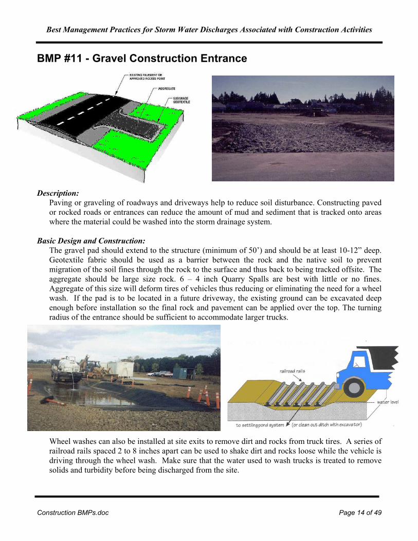
BMP #11 - Gravel Construction Entrance
Description: Paving or graveling of roadways and driveways help to reduce soil disturbance. Constructing paved or rocked roads or entrances can reduce the amount of mud and sediment that is tracked onto areas where the material could be washed into the storm drainage system.
Basic Design and Construction:
The gravel pad should extend to the structure (minimum of 50’) and should be at least 10-12” deep. Geotextile fabric should be used as a barrier between the rock and the native soil to prevent migration of the soil fines through the rock to the surface and thus back to being tracked offsite. The aggregate should be large size rock. 6 – 4 inch Quarry Spalls are best with little or no fines. Aggregate of this size will deform tires of vehicles thus reducing or eliminating the need for a wheel wash. If the pad is to be located in a future driveway, the existing ground can be excavated deep enough before installation so the final rock and pavement can be applied over the top. The turning radius of the entrance should be sufficient to accommodate larger trucks.
Wheel washes can also be installed at site exits to remove dirt and rocks from truck tires. A series of railroad rails spaced 2 to 8 inches apart can be used to shake dirt and rocks loose while the vehicle is driving through the wheel wash. Make sure that the water used to wash trucks is treated to remove solids and turbidity before being discharged from the site.

Best Management Practices for Storm Water Discharges Associated with Construction Activities
Construction BMPs.doc Page 15 of 49
The installation of a pressure washer is a relatively quick and low cost method of washing wheels and can be used on a Construction Entrance that uses the large aggregate. It can be added if the large aggregate in itself was insufficient to prevent tracking of sediments off site. It just takes a couple of minutes to clean the wheels.
If water is not yet available on the site a water truck can be used on the Construction Entrance (not as shown on the paved street) This will typically release larger amounts of water for short time intervals and some method for capturing this excess water and ensuring that it does not cause erosion and sediment control problems will have to be provided. Design Considerations: • Vehicle traffic should be restricted to only those locations fitted with a gravel entrance. • The entrance should be located to provide for maximum utility by all construction vehicles.
Maintenance: • Any material that makes it onto the road must be cleaned up immediately. • Additional rock should be added periodically to maintain a clean surface.

Best Management Practices for Storm Water Discharges Associated with Construction Activities
Construction BMPs.doc Page 16 of 49
BMP #12 – Road Sweeping
Description: When roads through a construction site are paved, they can quickly become coated with sediments. A common, but harmful, practice is to wash down the surface with water. The sediment laden runoff then drains to the storm water system, polluting the receiving water. Operations involving heavy vehicle traffic also produce elevated metal levels in storm water from vehicle brake shoes or clutches (copper) and tire particles (zinc).
Basic Design and Construction: Sweeping of paved roads, parking lots, and storage areas with a type of vacuum sweeper that incorporates HEPA filtration or other high efficiency method of filtration of the exhaust air from the sweeper to trap the very fine metallic particles found in road or parking lot dust can reduce these discharges to storm water. If the filter is not fine enough and well contained, materials that the vacuum picks up will be re-released into the air.
Tennant Company produces a series of sweepers (shown above), ranging from a small walk-behind model to as large as municipal street sized sweepers. The unique feature of Tennant’s products is a stainless steel hopper built in to the sweeper to collect dust and debris as it is picked up from the floor and passed through a polyester filter. When the hopper is full, it can be emptied directly into a dumpster or dump truck, minimizing the chance of particulate matter being re-released into the air. Information from the manufacturer reports that the sweepers will retain particles 10 microns (0.01 mm) or larger. The smaller size of the model and four-wheel steering makes it easy to maneuver in

Best Management Practices for Storm Water Discharges Associated with Construction Activities
Construction BMPs.doc Page 17 of 49
small spaces that traditional sweepers would not fit. Design Considerations:
Ensure that good control measures are implemented when dumping the contents of the sweeper and practice proper disposal methods for the emptied contents to ensure that there is no adverse environmental impact after spending so much effort in the initial clean-up.
Efficiency: The EV1 Sweeper is capable of collecting and containing up to 99.6% of particles as small as 2.5 microns in size. The elimination of particulates in storm water is related to the frequency of sweeping as is shown in comparisons of various types of sweepers in the graph on the preceding page.
BMP #13 - Dust Control
Description: In dry weather, soil is particularly prone to displacement by wind erosion on unpaved roads and construction sites. Use temporary controls such as palliatives, or chemical soil treatments that are applied as spray-on adhesives. The chemicals act to bind soil particles together and form a more durable, resilient ground surface. Common palliatives include calcium chloride, anionic asphalt emulsion, latex emulsion, and resin-water emulsions. Dust may also be controlled by reducing vehicular speeds, using street sweepers fitted with filters and vacuums, or planting vegetation cover. Irrigation is a temporary measure involving a light application of water to moisten the soil surface.
Best Management Practices for Storm Water Discharges Associated with Construction Activities
Construction BMPs.doc Page 18 of 49
The correct amount of water must be applied because excess water could lead to further erosion. Basic Design and Construction: • Since certain chemicals may be inappropriate for some soil types or application areas, the permittee
should check with the local government prior to application of the chemical treatments. • Minimize soil exposure by temporary or permanent soil stabilization controls, such as mulching,
seeding, applying topsoil, spreading coarse gravel or crushed stone, or planting trees. If existing vegetation on the site can be maintained, this will help in controlling dust.
• Install temporary or permanent windbreaks or barriers that reduce airborne particles by slowing wind velocities and causing the particles to drop. Large trees and shrubs left in place can provide wind barriers, while temporary measures include solid board fences, tarp curtains, sediment walls, crate walls, and bales of hay.
• Polymers can be used in tackifying and hydroseeding applications, either in temporary erosion control applications or as a part of a final revegetation project.
• In arid regions, use tillage or deep plowing of soil to provide dust control. Large clumps of soil are deposited on top of the dust particles, preventing their movement by wind or water.
• Use phased construction to expose only the minimum amount of soil necessary to wind and water. Design Considerations: • Vehicles should not be driven over the treated area to prevent the tracking of the chemicals to other
areas on or off the site. • Watering is the most common method of dust control, but is also the most temporary. The use of
chemicals to treat exposed surfaces generally provides longer dust suppression. • Dust may also be minimized by limiting the speed of vehicles on the construction site.
Maintenance: • Inspect the sites requiring dust controls frequently and reapply materials or controls as needed.
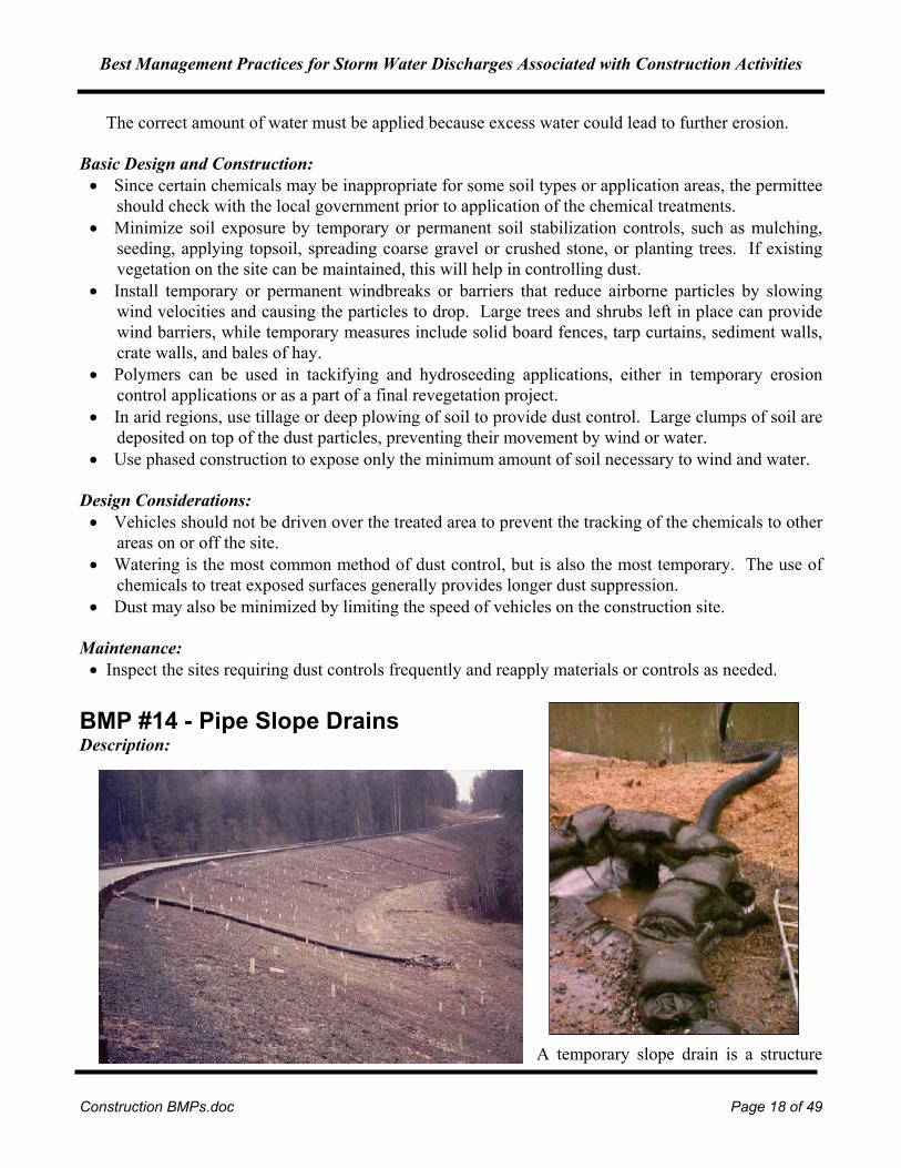
BMP #14 - Pipe Slope Drains Description:
A temporary slope drain is a structure
Best Management Practices for Storm Water Discharges Associated with Construction Activities
Construction BMPs.doc Page 19 of 49
used to convey water down the face of a cut or fill without causing erosion. Temporary slope drains are used in conjunction with berms along the edges of newly constructed slopes to prevent erosion. They are used along cut and fill slopes until permanent storm water drainage structures are installed. They can also be used to conduct water across a site without contamination. The inlets and outlets should be properly designed for adequate stabilization. The outlet area is particularly important, as the higher velocity water at the end of pipe can be an extremely erosive force. Outlet design and correct installation are the keys to the success of this type of control.
Basic Design and Construction: • Plastic lining; fiber matting; wooden flumes; metal, rigid, or flexible plastic pipe; and half round
pipe are commonly used. When plastic lining is used, a smooth, uniform ditch should be provided to prevent water from overflowing the sides. Fiber matting and plastic sheeting should not be used on slopes steeper than 4:1 except for short distances of 20 feet or less.
• The base for temporary slope drains should be compacted and concavely formed to channel the water or to hold the slope drain in place. Inlets should be properly constructed to channel water into the drain (see Figure 20, for example), and the drains anchored to withstand the force of the water. Anchoring can be accomplished by staking at approximately 10 foot intervals or by weighing down the drains with items such as riprap, sandbags, or compacted soil. Outlets should be constructed to reduce erosion downstream with items such as dumped rock, small sediment basins, or other approved devices.
• Temporary slope drains should be installed at frequent intervals along continuous unprotected slopes and at low points in the roadway profile grade. Each slope drain should not exceed 5 acres of drainage area. Pipe connections should be watertight and secure so joints will not separate. Pipe diameters should be calculated by a qualified engineer.
Design Considerations: • Washout along the pipe/ matting/ flume due to seepage, piping, and/or overflow; a washout may
occur because of inadequate compaction, insufficient fill, installation of drain too close to edge of slope, too steep a slope (open drains), too large a drainage area, or undersized conveyance channel.
• Overtopping of diversion caused by undersized or blocked pipe; drainage area may be too large. • Overtopping of diversion caused by improper grade of channel and ridge; maintain positive grade. • Erosion at outlet; pipe may not extended to stable grade or outlet stabilization structure may be
needed. • Displacement or separation of slope drain; the drain has inaccurate or insufficient anchorage. • All temporary slope drains should be removed when no longer necessary and the site should be
restored to match the surroundings. Maintenance: • Inspect temporary slope drains weekly and following rainfall events. Some critical points that
should be checked at each inspection are as follows. • Check inlet and outlet for sediment or trash accumulation; clear and restore to proper condition. • Check the fill over the pipe for settlement, cracking, or piping holes (seepage holes where pipe
emerges from dike); problems should be repaired promptly. • Check conduits for leaks or inadequate lateral support; problems should be repaired promptly.
Best Management Practices for Storm Water Discharges Associated with Construction Activities
Construction BMPs.doc Page 20 of 49
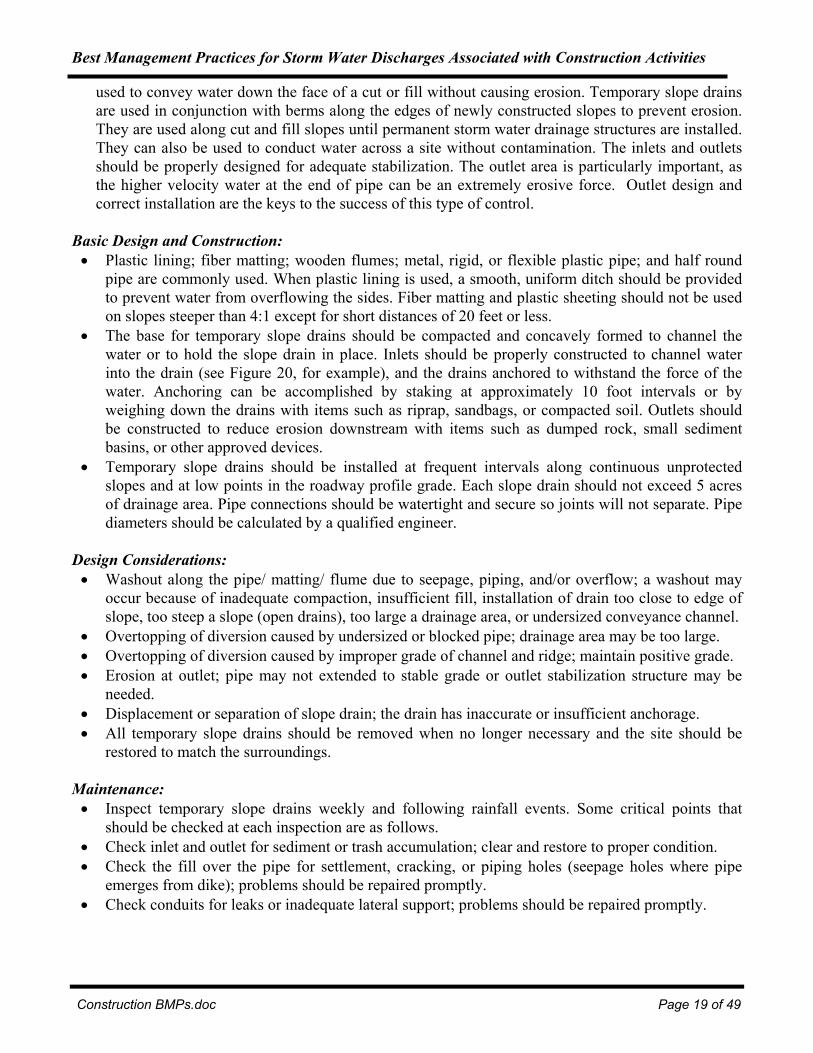
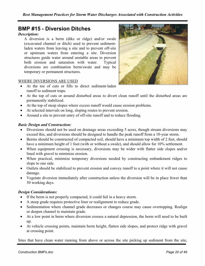
BMP #15 - Diversion Ditches Description:
A diversion is a berm (dike or ridge) and/or swale (excavated channel or ditch) used to prevent sediment-laden waters from leaving a site and to prevent off-site or upstream waters from entering a site. Diversion structures guide water around unstable areas to prevent both erosion and saturation with water. Typical diversions are combination berm/swale and may be temporary or permanent structures.
WHERE DIVERSIONS ARE USED • At the toe of cuts or fills to direct sediment-laden
runoff to sediment traps. • At the top of cuts or around disturbed areas to divert clean runoff until the disturbed areas are
permanently stabilized. • At the top of steep slopes where excess runoff would cause erosion problems. • At selected intervals on long, sloping routes to prevent erosion. • Around a site to prevent entry of off-site runoff and to reduce flooding.
Basic Design and Construction: • Diversions should not be used on drainage areas exceeding 5 acres, though stream diversions may
exceed this, and diversions should be designed to handle the peak runoff from a 10-year storm. • Berms should be constructed of compacted soil, should have a minimum top width of 2 feet, should
have a minimum height of 1 foot (with or without a swale), and should allow for 10% settlement. • When equipment crossing is necessary, diversions may be wider with flatter side slopes and/or
lined with gravel to minimize erosion. • When practical, minimize temporary diversions needed by constructing embankment ridges to
slope to one side. • Outlets should be stabilized to prevent erosion and convey runoff to a point where it will not cause
damage. • Vegetate diversion immediately after construction unless the diversion will be in place fewer than
30 working days. Design Considerations: • If the berm is not properly compacted, it could fail in a heavy storm. • A steep grade requires protective liner or realignment to reduce grade. • Sedimentation where channel grade decreases or changes course may cause overtopping. Realign
or deepen channel to maintain grade. • At a low point in berm where diversion crosses a natural depression, the berm will need to be built
up. • At vehicle crossing points, maintain berm height, flatten side slopes, and protect ridge with gravel
at crossing point. Sites that have clean water running from above or across the site picking up sediment from the site,
Best Management Practices for Storm Water Discharges Associated with Construction Activities
Construction BMPs.doc Page 21 of 49
should consider piping the water across the site or using diversion ditches lined with geotextile fabric. The ditch shown on the right is lined with geotextile fabric to prevent erosion and limit soil contact with storm water. This minimizes the storm water runoff that is of concern on the construction site. Maintenance: Permanent diversions should be checked following each rainfall until disturbed areas are stabilized. Inspect temporary diversions once a week and following each major rainfall event. Remove accumulated sediment from the channel. Check the dike, swale, and outlets and make necessary repairs immediately. Reseed areas that fail to establish a vegetative cover. Temporary diversions may be removed and blended with the natural topography when the area protected is permanently stabilized. BMP #16 - Level Spreaders Description:
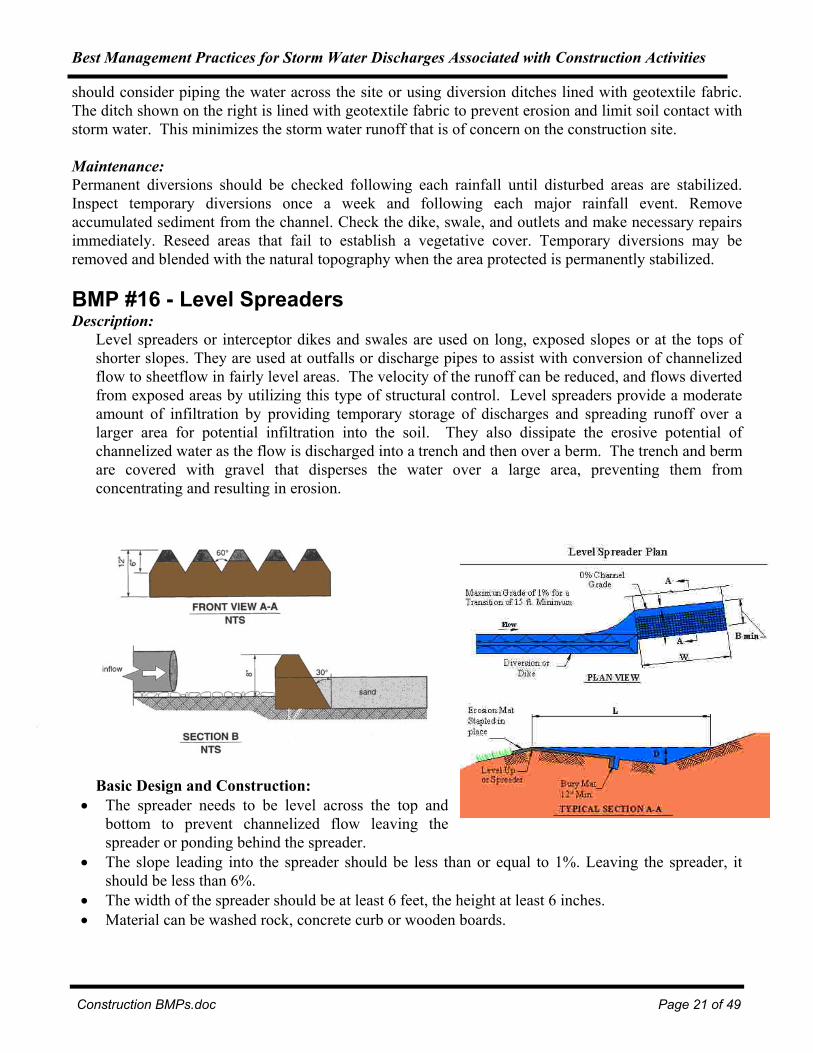
Level spreaders or interceptor dikes and swales are used on long, exposed slopes or at the tops of shorter slopes. They are used at outfalls or discharge pipes to assist with conversion of channelized flow to sheetflow in fairly level areas. The velocity of the runoff can be reduced, and flows diverted from exposed areas by utilizing this type of structural control. Level spreaders provide a moderate amount of infiltration by providing temporary storage of discharges and spreading runoff over a larger area for potential infiltration into the soil. They also dissipate the erosive potential of channelized water as the flow is discharged into a trench and then over a berm. The trench and berm are covered with gravel that disperses the water over a large area, preventing them from concentrating and resulting in erosion.
Basic Design and Construction: • The spreader needs to be level across the top and
bottom to prevent channelized flow leaving the spreader or ponding behind the spreader.
• The slope leading into the spreader should be less than or equal to 1%. Leaving the spreader, it should be less than 6%.
• The width of the spreader should be at least 6 feet, the height at least 6 inches. • Material can be washed rock, concrete curb or wooden boards.

Best Management Practices for Storm Water Discharges Associated with Construction Activities
Construction BMPs.doc Page 22 of 49
Maintenance: • Spreader should be checked after every rainfall event to make sure it is level and functioning as
intended.
BMP #17 - Outlet Protection
Description: Outlet protection involves the use of an energy-dissipating device at the outlet of a pipe or conduit to prevent excessive erosion (scour) from the discharge of runoff. Outlet protection is needed at outlets subjected to erosion and scour due to the exit velocity exceeding the allowable velocity for the soil discharged upon. Outlet protection structures take can be manufactured from a number of different materials.

Best Management Practices for Storm Water Discharges Associated with Construction Activities
Construction BMPs.doc Page 23 of 49
Basic Design and Construction: Concrete/Paved Outlet Protection: Concrete or paved outlet protection is a permanent form of structure and, therefore, should be designed by a qualified engineer. The design and installation of such a structure should follow plan specifications. Riprap Outlet Protection: Excavate subgrade below design elevation to allow for thickness of filter and riprap. Compact any fill used in the subgrade to the density of the surrounding undisturbed material. When applicable, smooth the subgrade to prevent tears of the filter fabric. Even if not shown on plans, filter stone, fabric, or a blanket should be placed prior to placing the riprap to help prevent subgrade erosion. Filter fabrics should be of extra-strength quality and should be installed in continuous sections, placing the upstream section of fabric a minimum of 1 foot over the downstream section of fabric. Fabrics that are torn during riprap installation should be fully replaced. Install riprap of the size and thickness as shown on plans to ensure a minimum thickness of 1.5 times the maximum stone diameter. Maintain final structure to the lines and elevations as shown in plans, taking care not to place stones above the finished grade.
Apron Installation: Nondefined Channel: Apron should be constructed on a zero grade, aligned straight, and be long enough to adequately dissipate energy. There should be no restrictions or overfall from the apron end to the receiving grade.
Well-Defined Channel: Apron should be straight and properly aligned with the receiving stream. The apron should extend to the top of the bank and be long enough to adequately dissipate energy. There should be no restrictions or overfall from the apron end to the receiving channel.
For outlet piping of relative small diameter say 18 inches or less, completely burying the outfall side of the pipe in rip rap would provide the velocity diffusing feature without concern for the length of protection needed. Design Considerations: • If the foundation not excavated deep enough or wide enough, riprap will restrict flow across
sections, resulting in erosion around apron and scour holes at outlet. • If the riprap apron is not on a zero grade, erosion will result downstream. • If the stones are too small or not properly graded, this results in movement of stone and
downstream erosion. • If riprap not extended far enough to reach a stable section of channel or adequately dissipate
energy, there will be downstream erosion. • If an appropriate filter is not installed under riprap, this may result in stone displacement and
erosion of the foundation. Maintenance: • Riprap outlet structures do not require much maintenance when properly installed, but they should
be checked after heavy rains for erosion at sides and ends of the apron and for stone displacement. Repair damage immediately using appropriate stone sizes.
• Modify size and depth as needed to prevent erosion and scouring.
Best Management Practices for Storm Water Discharges Associated with Construction Activities
Construction BMPs.doc Page 24 of 49
• Check outsides of pad to verify that pad is wide and long enough to prevent erosion along the edges.
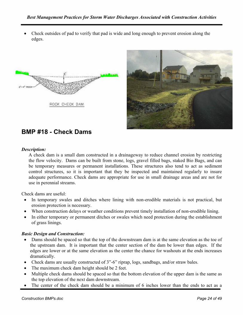
BMP #18 - Check Dams Description:
A check dam is a small dam constructed in a drainageway to reduce channel erosion by restricting the flow velocity. Dams can be built from stone, logs, gravel filled bags, staked Bio Bags, and can be temporary measures or permanent installations. These structures also tend to act as sediment control structures, so it is important that they be inspected and maintained regularly to insure adequate performance. Check dams are appropriate for use in small drainage areas and are not for use in perennial streams.
Check dams are useful: • In temporary swales and ditches where lining with non-erodible materials is not practical, but
erosion protection is necessary. • When construction delays or weather conditions prevent timely installation of non-erodible lining. • In either temporary or permanent ditches or swales which need protection during the establishment
of grass linings. Basic Design and Construction: • Dams should be spaced so that the top of the downstream dam is at the same elevation as the toe of
the upstream dam. It is important that the center section of the dam be lower than edges. If the edges are lower or at the same elevation as the center the chance for washouts at the ends increases dramatically.
• Check dams are usually constructed of 3”-6” riprap, logs, sandbags, and/or straw bales. • The maximum check dam height should be 2 feet. • Multiple check dams should be spaced so that the bottom elevation of the upper dam is the same as
the top elevation of the next dam downstream. • The center of the check dam should be a minimum of 6 inches lower than the ends to act as a

Best Management Practices for Storm Water Discharges Associated with Construction Activities
Construction BMPs.doc Page 25 of 49
spillway for runoff and prevent water from flowing around the check dam or eroding the bank. • Overflow areas should be stabilized to resist erosion. • Stone check dams should use 3 inch or larger stone with side slopes of 2:1 or flatter and should be
keyed into the sides and bottom of the channel a minimum depth of 2 feet. The drainage area for a stone check dam should not exceed 50 acres.
• Log dams should be constructed with 4 to 6 inch diameter logs and should be embedded a minimum of 2 feet. The drainage area for a log check dam should not exceed 5 acres. Note that removal of a log check dam can result in more soil disturbance than removal of other types of check dam.
• Straw bales are effective with low flows and should be overlapped and embedded a minimum of 4 inches with stakes angled slightly upstream. The drainage area for straw check dams should not exceed 2 acres.
Design Considerations: • Check dams are designed for velocity reduction and erosion control and are not intended to trap
sediment, although sediment buildup will often occur. Sedimentation can clog the dam causing ponding which may kill the vegetative lining if submergence after rains is too long and/or siltation is excessive.
• If the overflow area not stabilized, downstream erosion may result. Stabilize the streambed and bank with riprap or equivalent. Extension of downstream embankments to stable grades is also effective.
• When overflow occurs at the abutments, the spillway will need to be lowered or enlarged. • Check dams may be removed when their useful life has been completed. All stones should be
removed from grass channels that require mowing. Care should be taken when removing check dams so as not to damage channels that are permanent.
Maintenance: • Regularly inspect a check dam to ensure the dam has not been breached or otherwise damaged. The
center elevation of the dam should be checked to ensure it is lower than the ends of the dam. • Sediment accumulation behind the dam should be removed as needed to prevent damage to channel
vegetation and to allow the channel to drain through the dam; otherwise remove sediment when it reaches half the dam's height.
• Repair a damaged check dam promptly so the check dam will be fully functional for the next runoff event.
BMP #19 – Terracing

Best Management Practices for Storm Water Discharges Associated with Construction Activities
Construction BMPs.doc Page 26 of 49
Description: Terraces are constructed across slopes and form a series of channels and earthen embankments that reduce erosion by breaking the long slope into several shorter sections. The speed of the runoff is thereby reduced as is the amount of sediment loss. Runoff is collected in the terrace channel and can be stored for infiltration into the soil or diverted through some kind of erosion resistant outlet.
Efficiency: Soil loss can be reduced by 50 percent or more. Land Slope Reduction in Erosion 1-12% 70% 12-18% 60% 18-24% 55%
BMP #20 - Sediment Basin
Definition:
A basin constructed above original ground surface to capture sediment from upland sources. Sediment basins are earthen embankments constructed across a minor watercourse to form a sediment trap and water detention basin. A perforated stand pipe is generally used to slow the release of water from the basin, thus allowing the suspended soil particles time to settle. The water passes from the stand pipe to a subsurface pipe which carries the water downslope to a stable outlet.
Basic Design and Construction: • Basins should be located in low gradient reaches of stream. • Build the basin large enough to control the expected volume of water runoff. • Use fill material free of sod, roots, and stones larger than 6 inches in diameter. It should also have
correct moisture content for adequate compaction.
Design Considerations: • Potential impacts of dam failure. • Obtaining necessary permits from regulatory agencies. • Once the sediment basin is constructed, accessibility of site by equipment and vehicles to remove
accumulated sediment is limited.

Best Management Practices for Storm Water Discharges Associated with Construction Activities
Construction BMPs.doc Page 27 of 49
• Availability of suitable spoil locations on-site and feasibility off-site spoil location (End-Hauling). • Temporary stream flow diversion away from work area if operating in a perennial stream. • Trees, stumps, rocks & boulders removed to construct the sediment basin should be replaced.
Maintenance: • Excavate accumulated sediment regularly. • Repair of grade structures or channel lining as needed. • Remove obstructions which may plug outlet. • Reseed and fertilize as necessary to maintain vegetative cover.
Efficiency:
Average – 70% percent removal of TSS (EPA, 1999) Range – 55% - 100%
BMP #21 - Vegetated Filter Strip Description:
Vegetated filter strips (VFS) are land areas of either indigenous or planted vegetation, situated between a potential pollutant source area and a surface water body that receives runoff. They remove sediment and other pollutants from runoff and wastewater by infiltration, deposition, absorption, adsorption, and decomposition, reducing the amount of pollutant entering the surface waters. VFS are most effective in removing sediments. The longer the flow path of storm waters through vegetation, the better the pollutant removal.
Basic Design and Construction: • All trees, brush, stumps, rocks and similar
materials that can interfere with installing the filter strip should be removed.
• The appropriate size and shape of the filter strip is dependent on a number of factors: type and quantity of pollutant, soil characteristics, infiltration rate, permeability, percent slope, etc.
• The contributing area should be limited to 10 acres and slopes should be moderate to prevent channelized flow from forming. Length and width should be 50 feet and 20 feet at a minimum (EPA, 1996). A roughened surface is preferred to slow surface runoff and thus increase infiltration. VFS need the following elements to work correctly:
• A device such as a level spreader to ensure that runoff passes through as sheet flow. • Plants selected for filter strips should have dense top-growth and provide good, uniform soil cover,
and a fibrous root system for stability. The type of vegetation selected should be adapted to local soil and climatic conditions and have good regrowth following dormancy and cutting.
• Grasses are more effective than broadleaf plants for erosion control since they form a dense sod, have a fibrous root system and a more complete ground cover.
• Regrading may be necessary to ensure a gentle slope of no more than 5 percent.

Best Management Practices for Storm Water Discharges Associated with Construction Activities
Construction BMPs.doc Page 28 of 49
Design Considerations: • VFS are designed to be used under conditions in which runoff passes over the vegetation in a
uniform sheet flow. Such a flow is critical to the success off the filter strip. If runoff is allowed to concentrate, it will be easily inundated and will not perform to its fullest capability.
• A filter strip is an edge-of-the-site BMP and should be used in conjunction with other BMPs that are designed to reduce soil loss.
• Quality of vegetation in the filter strip is an important factor in determining effectiveness. Poor quality vegetation may have increased amounts of sediment leaving the filter.
Maintenance: • Frequent inspections are necessary the first few years until vegetation is well established. • Periodic regrading and sediment removal may be necessary. • Plant density should be encouraged by fertilizing and weeding periodically. Reseeding may also
be necessary. • Minimize the development of erosion channels within the filter. Even small channels may allow
runoff to bypass the filter. Efficiency: Average – 70% percent removal of TSS (EPA, 1999) Range – 20% - 80% BMP #22 - Bioswales
For further information on Bioswales see the Biofilters document at http://www.deq.state.or.us/nwr/stormwater.htm. Description:
Swales are shallow ditches with grass or other vegetation that act as filters for runoff from frequent storms. The principle form of treatment is the settling out of pollutants and the use of vegetation to take up the dissolved fraction. For best results a swale should be designed to deal with the peak runoff for a two year, 24 hour storm event. Bioswales do well with first flush runoff, are economically feasible, improve aesthetics and have minimum environmental impacts. The organic

Best Management Practices for Storm Water Discharges Associated with Construction Activities
Construction BMPs.doc Page 29 of 49
topsoil layer is good for degrading petroleum solvents, heavy metals, nutrients and hydrocarbons. They can be placed anywhere with careful site design, but are best when located where water can pond and settle out sediments, such as at a storm water outfall, commercial development or road side.
Basic Design and Construction: • Critical design elements: size of drainage area to be treated, location of bioretention areas, sizing
guidelines, calculate water budget • Biofiltration is suitable for smaller sites 10 or less acres • Needs a minimum width of 20 feet • Must be graded to create sheet flow not a concentrated stream. Sheet flow decreases the chance of
producing gully erosion and distributes contaminants over a wider area. Level spreaders (i.e. slotted curbs) can be used to facilitate sheet flow.
• Best when used for treatment and conveyance of storm water after a settling pond. • Best at 200 feet in length, in tight spaces obtain more length by using a curved path. Should have a
maximum bottom width of 50 feet. One foot high check dams should be installed every 50 feet starting 20 feet downstream from the inflow point.
Design Considerations: • Do not use on steep, unstable slopes or landslides.
Maintenance: • Vegetation in the bioswale should be trimmed every year or two to prevent woody species from
taking over. Clippings from plants should be disposed of properly as they may have absorbed hazardous toxins.
• Regrading may be necessary to reshape the shallow-broad shape as sediments collect and form pools. As with plant waste, sediments should be removed and disposed of properly.
Efficiency:
Total Suspended Solids – 83 to 92%, Lead – 67%, Copper – 46%, Total phosphorus – 29 to 80%, Total zinc and aluminum – 63%, Dissolved zinc – 30%, Oil/grease – 75%, Nitrate-N – 39 to 89%
BMP #23 - Constructed Wetlands For further information on Bioswales see the Biofilters document at http://www.deq.state.or.us/

Best Management Practices for Storm Water Discharges Associated with Construction Activities
Construction BMPs.doc Page 30 of 49
nwr/stormwater.htm. Description:
Constructed wetlands are man-made, engineered wetland areas created through a combination of excavation and/or berming. The basic types of constructed wetlands are shallow marsh, 2 or 3 celled pond/marsh, extended-detention wetland, and pocket wetland. Extended-detention and pocket wetlands are less effective in removal of some types of pollution than other types of wetlands. They are particularly good for the removal of nutrients and conventional pollutants such as oil and grease and some heavy metals.
Basic Design and Construction: • Suitable for larger sites, up to 100 acres. • Shape should be long, narrow and irregular since these are less prone to short circuiting, are more
effective and maximize the treatment area. • Soils should be tested to determine suitability. Best when located in clay loams, silty clay loams,
sandy clays, silty clays and clays. • The permanent pool depth should be between 3 to 6 feet, plus one foot of dead storage for
sediment. Six feet is the maximum depth or the pond will stratify in summer and create low oxygen conditions which result in the re-release of phosphorus and other pollutants. In addition if the pond is deeper than 6 feet it will likely pollute the groundwater.
• Cannot be used in areas with shallow depth to bedrock or unstable slopes. • Needs to have a shallow marsh system in association to deal with nutrients. • Should be multi-celled preferably three of equal sizes, the first cell should be 3 feet deep to trap
coarse sediments and slow turbulence. They need to be designed as a flow through facility, and the pond bottom should be flat to facilitate sedimentation.
• Side slopes should be 2:1, not steeper than 3:1, and 10 to 20 feet in width. A length to width ratio of 5:1 is preferred, with a minimum ratio of 2:1 to enhance water quality benefits. The longer length allows more travel time and opportunity for infiltration, biofiltration and sedimentation.
• Pond berm embankments over 6 feet should be designed by a registered engineer. Berm tops should be 15 feet wide for maintenance access and should be fenced for public safety.
• Baffles can be used to increase the flow path and water residence time. • Should have an overflow system/emergency spillway to deal with a 100 year 24 hour flood, and a
gravity drain. • Access to the wet pond is to be limited with a gate and signs posted. • For mosquito control either stock the pond with fish or allow it to be drained for short periods of
time (do not kill the marsh vegetation). • Constructed wetland is more complex, with more vegetation, and shallower with greater surface
area, hydrologic factors (flow) play a larger part in siting. • Selection of vegetation should be done by a wetland specialist. • Oil/water separators can be used prior to the constructed wetland depending upon the surrounding
land uses. • Relatively low maintenance costs. • Fence off for safety and to protect plants/wildlife.
Design Considerations: • Constructed wetlands have larger land requirements for equivalent service compared to wet ponds.

Best Management Practices for Storm Water Discharges Associated with Construction Activities
Construction BMPs.doc Page 31 of 49
• Relatively high construction costs. • Delayed efficiency until plants are well established (1 to 2 seasons). • Need a buffer width of 25 to 50 feet. • Water level fluctuations can kill plants.
Maintenance:
Maintenance is of primary importance. The site must be responsible. A maintenance plan needs to address removal of dead vegetation (that release nutrients) prior to the winter wet season, debris removal from trash racks, sediment monitoring in forbays and in basin are likely to contain significant amounts of heavy metals and organics (regular testing is advised).
Efficiency:*
Heavy metals = 40-80% Nitrate = 65% Total Phosphorus = 40-80% COD = 2 Total Nitrogen = 40-60% Total Copper, Lead, Zinc = 80-95% Sol. Reactive Phosphorus = 75% Ammonia = -43
*Higher efficiencies are associated with the use of larger pond/marsh area and volume. These efficiencies assume that the intensity of the storm water inflow does not exceed the capacity of the wetlands and that the pollutants are not in a concentrated form from a large spill or discharge.
BMP #24 - Excavated Sediment Trap Description:
Sediment traps allow sediments to collect in runoff across exposed ground to settle out before runoff is released from the site. They are placed on the downslope side of the exposed areas. Sediment must be removed periodically to maintain the effectiveness of the trap in capturing sand sized sediment from upland sources. Sediment traps should be located in natural deposition areas as evidenced by sediment deposits or an abrupt change in grade.
Basic Design and Construction: • The stream channel above and below the proposed excavation should be generally stable. • A stream profile survey and cross sections through the proposed excavation shall be done to
determine limits of excavation, depth of cut, and excavation volume. • The storage capacity of the basin should be sized according to anticipated rate of sediment
accumulation and frequency of maintenance. The desired capacity of the sediment trap should be balanced with the need to conform the sediment trap to the surrounding topography.
• Excavated channel grade should not exceed channel grade immediately above excavation. • The outlet elevation should not be greater than the original channel elevation. If the outlet
elevation is to be raised see design for Impoundment Basin. • Excavated side slopes should stable from erosion under ponded conditions. • The sediment trap inlet and outlet shall be stable for a 50yr-24hr storm. The necessary stability can
be achieved with the aid of channel stabilization measures including grade control structures and channel lining.
Design Considerations: • Sediment traps are based on the amount of unstabilized area. Please consult local ordinances as to
specific size requirements.

Best Management Practices for Storm Water Discharges Associated with Construction Activities
Construction BMPs.doc Page 32 of 49
• When choosing a location for a trap, make sure that the site will be low enough to accommodate any diversion berms, dikes or pipes.
• The trap must discharge runoff onto a stabilized area. Maintenance: • Repair grade structures or channel lining as needed. • Remove obstructions which may divert stream flow. • Sediment must be removed when it reaches half of the total sediment storage area. • The trap should be checked after all significant rainfall for effectiveness in trapping sediments and
for repairs to the trap. Efficiency: Average 60% percent removal of TSS (EPA, 1999). BMP #25 - Continuous Berm Definition:
A continuous berm is a 12” by 12” fabric encapsulated tube of sand, aggregate or native soil. Multi-purpose in application, it can be used to intercept and divert sheetflow runoff, detain and pond sediment laden storm water or reduce flow velocities. By choosing the appropriate geosynthetic fabric, the berm can be designed to filter or contain sheet flows. The continuous berm can be used in conjunction with or in lieu of silt fences, straw bales, and other sediment control structures. The advantages of the CBM are that it reduces labor and backfilling, and eliminating trenching and staking.
Basic Design and Construction:
Continuous Berm Machine is a material feeding and fabric rolling system that creates a berm by wrapping geotextile fabric around sand, aggregate, or soil. Trenching is not necessary because the flexibility of the material and fabric allows the berm to form a tight seal with slightly irregular soil surfaces. Neither is staking necessary because of the weight of the berm (100 1bs./ft3).
• Use geosynthetic fabrics having a high mass per unit area and high elongation properties for
forming a continuous berm. Non-woven needle punch, woven monofilament and spun bond materials are acceptable. A non-woven needle punch fabric is highly recommended for most construction site applications. Materials with open weave cannot be used in the CBM.
• Fill continuous berm with sand, aggregate, or local soil as specified. • Drainage of ponded waters is dependent upon fabric flow rates, infill material, and modifications to
drainage chambers, if any. • When a continuous berm is to function as a sediment trap, it is sometimes advisable to construct
the berm with one or more 3/4 to 1 1/2 inch (20 to 38 mm) diameter aggregate filled drainage chambers. Length of drainage chambers is variable, but typically 6 to 10 feet (1.8 to 3 m). Drainage chambers must be located at low points to effect adequate drainage of ponded waters.
• Accelerated discharge through non-woven fabric can be effected by cutting 2 to 4 vertical slits in the upstream side of a berm's drainage chamber and inserting a 2 inch (51 mm) diameter PVC pipe 4 to 6 inches (101-152 mm) into the drainage chamber on the downstream side.
• Once a continuous berm has been placed, additional sealing of the berm to underlying ground surface occurs by having someone walk along the top of the berm. When continuous berms are

Best Management Practices for Storm Water Discharges Associated with Construction Activities
Construction BMPs.doc Page 33 of 49
stacked one on top of another to create a higher barrier, it is advisable to use a small vibratory plate compactor over the top of each layer of berm to compact infill materials, and provide a very stable base for subsequent berm layers.
Maintenance: • Maintenance of a continuous berm requires minimal effort. • If evidence of piping is detected, compacting loose soil in the area of failure results in mitigating
the problem. • If vehicles run over the berm causing damage, the area is typically repaired by re-stapling the
fabric. In the event of major damage, a new section of berm can be placed in front of the damaged section. When the berm is no longer needed, removal is completed by slitting the berm, spilling the fill material and incorporating it into the existing soil, and removing the fabric. Alternatively, the berm may be cut into 10 to 14 foot sections, and after stapling section ends, removed for future use.
Efficiency: The Continuous Berm is rated at up to 95% efficiency in sediment removal. BMP #26 – Compost Berm Definition:
A compost berm is an efficient way of preventing sediment and turbidity discharges from a construction site. Yard debris compost is used to build a dike which filters the storm water runoff. Most sediment and colloidal soil particles are negatively charged. Compost is positively charged which tends to attract and hold the soil particles.
For further information on Compost for Erosion Control see the Biofilters document at http://www.deq.state.or.us/ nwr/stormwater.htm.
Basic Design and Construction: The basic compost berm consists of a 2 feet wide by 1 foot high continuous pile of compost. The compost should be yard debris, leaf, or composted biosolids from a sewage treatment plant. The compost grade can be either two-inch minus, one inch minus, or half-inch minus. The grade should be associated with the slope of the area behind the berm. Steeper slopes generally should call for larger sized compost. Sheet flow of runoff is a must upgradient of the berm. This may be

Best Management Practices for Storm Water Discharges Associated with Construction Activities
Construction BMPs.doc Page 34 of 49
established by the application of a 2 inch thick compost layer on the slope, a silt fence installation, straw bales, or some other method for dispersing or preventing concentrated flows from occurring. The down stream side of the berm should not be bare soil or the runoff will pick up sediment and turbidity after the berm.
Maintenance:
The berm should be regularly inspected to ensure that the berm does not blow out form concentrated flows and to ensure that the compost does not become saturated, plugged, or rendered ineffective by some other method. This is a visual observation that must be made during storm water runoff. Turbidity breakthrough will be evident by muddy water flowing through the berm.
Efficiency: On a 34 % slope, test have shown that settleable and suspended solids reduction were reduced 91.9% and 95% respectively over that discharged through a silt fence.
BMP #27 – Compost Sock Description: A Compost Sock is an approximate 12 inch
diameter close weave sock either of synthetic or cotton fiber filled with mixed yard debris compost. It is heavy but can be moved. Deformation of the sock is sufficient to make a good seal between the sock and concrete or asphalt surfaces. It is blown on site to the desired length. The synthetic sock deteriorates in a couple of years and the cotton sock deteriorates in about a year. Seed can be blown in with the compost.
They can be staked and used as a check dam. A special sock tube is used which has a downstream skirt to protect the stream bed from any damage that may be caused from water overflowing the sock and undercutting the stream bed. The sock, when used as a check dam must be staked to prevent the water pressure from moving it.

Best Management Practices for Storm Water Discharges Associated with Construction Activities
Construction BMPs.doc Page 35 of 49
Efficiency: This is highly ineffective on turbidity and suspended solids. More than one sock may have to be used side-by-side.
BMP #28 - Sediment Fences Description:
Sediment fencing consists of a geotextile fabric usually 36 inches in width with regular spaced pockets for supporting posts. The weave of the fabric determines the size of the soil particle retained by the silt fence. As heavy large sized particles are retained, they create a build up effect, which will retain smaller sized particulate similar to the way an air filter becomes more effective as it retains dust. At some point the material behind a sediment fence becomes too efficient, causing the material to rise higher behind the fence and start the retention cycle all over again.
Sediment fencing cause heavy soil particles to be retained both through a filtering operation and through the creation of a small settling basin up slope of the fence through restriction and retardation of the runoff flow velocity. Sediment fence spacing on slopes should be at no greater distance than:
Slope Spacing <10% 300 ft. <15% 150 ft. <20% 100 ft. <30% 50 ft. <50% 25 ft. Stock Pile Slope >50% 25 ft. Basic Design and Construction: • Sediment fence must be trenched at least 6” into the ground. The use of a “ditch witch” or other
mechanical means is helpful. • The sediment fence must be stretched tight between the posts. Do not allow the fence to sag or break
away from the fence posts.
TOP VIEW
4' -
0"
6" 3' -
0"
Sediment Fence
NOTES:
1. BURY BOTTOM OF FILTER FABRIC 6" MIN. VERTICALLY BELOW FINISHED GRADE.2. 2" x 2" FIR, PINE, OR STEEL FENCE POSTS.3. STITCHED LOOPS TO BE INSTALLED UPHILL SIDE OF SLOPE.4. COMPACT NATIVE FILL IN ALL AREAS OF FILTER FABRIC TRENCH.
FRONT VIEW SIDE VIEW
INTERLOCKED2" x 2" POSTSAND ATTACH.
ANGLE BOTH ENDS OF SEDIMENT FENCETO ASSURE SOIL IS TRAPPED.
6' - 0"
NTS

Best Management Practices for Storm Water Discharges Associated with Construction Activities
Construction BMPs.doc Page 36 of 49
• More than one row of sediment fence may be required. Fencing should be located no more than 100’ from the upper edge of a disturbed area. Space silt fencing in rows no greater than 100’.
Design Considerations:
Sediment fences are effective only in sheet flow conditions and should not be installed across streams or other concentrated flows. Turbidity reduction overall generally does not occur. The data indicates that a silt fence may in fact be detrimental in controlling turbidity. At best, a silt fence can be used to retain the heavy settleable solids while other erosion controls are necessary to reduce turbidity.
Maintenance:
Frequent removal of accumulated sediment and replacement of fabric should occur at least every six months when exposed to fine clay sediment runoff. A more proactive approach would be to replace the sediment fence every 30 days when exposed to clay-silt-loam runoff.
Efficiency: This data indicates that sediment fencing can reduce TSS from 8 to 76% compared with no erosion control. According to research conducted by Muson, 1991; Fisher et al, 1984; and Minnesota Pollution Control Agency, 1989, the following ranges of control can be obtained for TSS by using sediment fencing:
Sand 80% - 99% Silt-Loam 50% - 80% Silt-Clay-Loam 0% - 20% Local Oregon Tests:
Murray Boulevard St. Johns Landfill
Turbidity NTU
Total Suspended Solids mg/l
Turbidity NTU
Total Suspended Solids mg/l
Storm Date
Control Sediment Fence
Control Sediment Fence
Control Sediment Fence
Control Sediment Fence
3/2/93 410.0 480.0 380.0 255.0 150.0 160.0 2,300.0 3,900.03/4/93 320.0 280.0 660.0 610.0 97.0 49.0 3,400.0 1,800.03/16/93 330.0 340.0 410.0 100.0 81.0 120.0 710.0 540.03/19/93 140.0 140.0 630.0 220.0 95.0 48.0 4,800.0 1,400.03/23/93 420.0 420.0 2,300.0 625.0 340.0 570.0 31,000.0 26,000.0Mean 324.0 332.0 876.0 362.0 152.6 189.4 8,442.0 6,348.0Std. Dev. 112.4 131.6 805.9 240.3 108.0 218.1 12,699.0 11,003.6Min. 140.0 140.0 380.0 100.0 81.0 48.0 710.0 440.0Max. 420.0 480.0 2,300.0 625.0 340.0 570.0 31,000.0 26,000.0Range 280.0 340.0 1,920.0 525.0 259.0 522.0 30,290.0 25,560.0Median 330.0 340.0 630.0 255.0 97.0 120.0 3,400.0 1,800.0

Best Management Practices for Storm Water Discharges Associated with Construction Activities
Construction BMPs.doc Page 37 of 49
BMP #29 - Straw Wattles
Description:
Straw wattles are manufactured tubular black plastic netting filled with rice straw. They are approximately nine inches in diameter and twenty-five feet long, weigh about 35 pounds and are easy to install. They can be installed on steep slopes and must be staked in position. Straw wattles act to disperse runoff laterally and trap sediments on the up-slope. If the soils are poor and need to be fertilized, the mini-terraces formed by the wattles encourage the nutrients to stay on the slope.
Basic Design and Construction: • A trench should be excavated in which to lay the
wattles, ensuring that water does not seep underneath the wattles.
• Wattles are placed along the contour of the slope to reduce water flows and trap sediments.
• Stakes should be driven in perpendicular to the slope.
• Make sure the wattle fits snugly against the adjoining wattle, without gaps or cracks.
Maintenance:
The sediment behind the wattles needs to be removed regularly and replacement of the wattles should be made every three years or when they appear to become plugged, i.e. water will not pass through.
Efficiency: When installed correctly they can equal the efficiency of straw bales at retaining sediments.
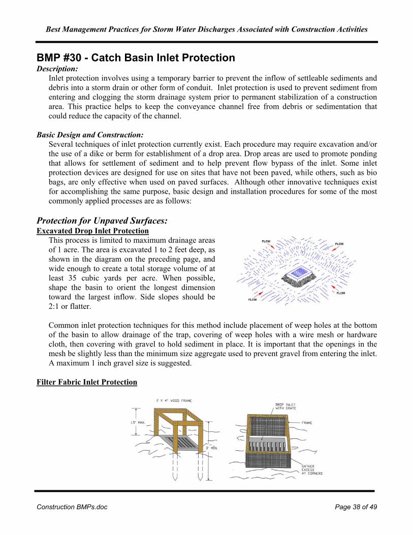
Best Management Practices for Storm Water Discharges Associated with Construction Activities
Construction BMPs.doc Page 38 of 49
BMP #30 - Catch Basin Inlet Protection Description:
Inlet protection involves using a temporary barrier to prevent the inflow of settleable sediments and debris into a storm drain or other form of conduit. Inlet protection is used to prevent sediment from entering and clogging the storm drainage system prior to permanent stabilization of a construction area. This practice helps to keep the conveyance channel free from debris or sedimentation that could reduce the capacity of the channel.
Basic Design and Construction: Several techniques of inlet protection currently exist. Each procedure may require excavation and/or the use of a dike or berm for establishment of a drop area. Drop areas are used to promote ponding that allows for settlement of sediment and to help prevent flow bypass of the inlet. Some inlet protection devices are designed for use on sites that have not been paved, while others, such as bio bags, are only effective when used on paved surfaces. Although other innovative techniques exist for accomplishing the same purpose, basic design and installation procedures for some of the most commonly applied processes are as follows:
Protection for Unpaved Surfaces: Excavated Drop Inlet Protection
This process is limited to maximum drainage areas of 1 acre. The area is excavated 1 to 2 feet deep, as shown in the diagram on the preceding page, and wide enough to create a total storage volume of at least 35 cubic yards per acre. When possible, shape the basin to orient the longest dimension toward the largest inflow. Side slopes should be 2:1 or flatter. Common inlet protection techniques for this method include placement of weep holes at the bottom of the basin to allow drainage of the trap, covering of weep holes with a wire mesh or hardware cloth, then covering with gravel to hold sediment in place. It is important that the openings in the mesh be slightly less than the minimum size aggregate used to prevent gravel from entering the inlet. A maximum 1 inch gravel size is suggested.
Filter Fabric Inlet Protection
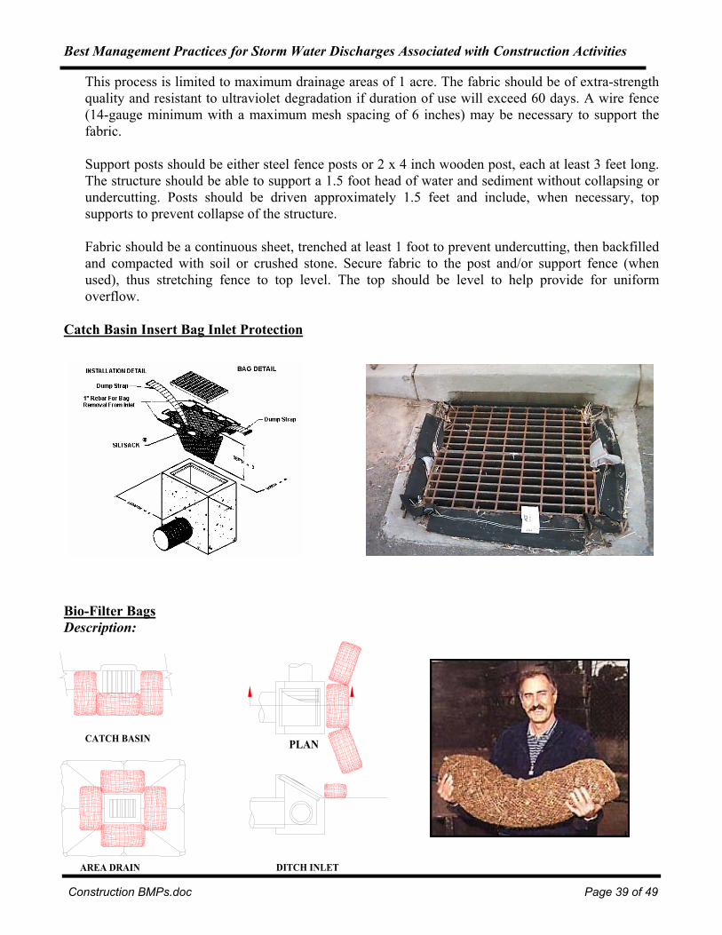
Best Management Practices for Storm Water Discharges Associated with Construction Activities
Construction BMPs.doc Page 39 of 49
This process is limited to maximum drainage areas of 1 acre. The fabric should be of extra-strength quality and resistant to ultraviolet degradation if duration of use will exceed 60 days. A wire fence (14-gauge minimum with a maximum mesh spacing of 6 inches) may be necessary to support the fabric. Support posts should be either steel fence posts or 2 x 4 inch wooden post, each at least 3 feet long. The structure should be able to support a 1.5 foot head of water and sediment without collapsing or undercutting. Posts should be driven approximately 1.5 feet and include, when necessary, top supports to prevent collapse of the structure. Fabric should be a continuous sheet, trenched at least 1 foot to prevent undercutting, then backfilled and compacted with soil or crushed stone. Secure fabric to the post and/or support fence (when used), thus stretching fence to top level. The top should be level to help provide for uniform overflow.
Catch Basin Insert Bag Inlet Protection
Bio-Filter Bags Description:
DITCH INLET
PLAN
AREA DRAIN
CATCH BASIN
Best Management Practices for Storm Water Discharges Associated with Construction Activities
Construction BMPs.doc Page 40 of 49
Bio-filter bags (Biobags) are woven 12” by 9” by 40” nylon mesh bags containing bark and/or wood chips. There are at least two sizes of biobags. The most common size of biobag is approximately eighteen inches long. They are commonly used as an alternative to straw bales to remove energy from concentrated flows or for protection around catch basins. Biobags are much lighter than straw bales and must be staked down to keep them in place.
Basic Design and Construction: Biobags can be used in a number of locations and in a variety of arrangements around the storm-drains. They should be positioned so that there are no gaps between the bags that could allow runoff to reach the stormdrains unfiltered. Due to their high maintenance and potential for damage or displacement on paved areas, biobags should not be used on paved areas after the first layer of pavement is installed.
Design Considerations:
Biobags are more permeable than straw bales, but slow water sufficiently to trap sand, silt and clay. They fit the contours of the land, avoiding the bridging problem of straw bales. They hold together better, and can therefore be removed more easily when saturated. Wildlife won’t tear them apart to eat them and they will not introduce grass and weed seeds to the site.
Maintenance: • Removing accumulated sediment from behind the biobag to ensure efficient sediment removal. • Replace biobags whenever they become plugged with sediments or damaged, such as when
vehicles run over or dislodge them. With their much more open voids and their ability to retain larger particle sizes of sediment, it is very important to replace the biobag when water can no longer pass through them.
Design Considerations: • Sediment fills the designated trap and enters the storm drain; the sediment-producing area is too
large for installed trap or the inlet is not properly maintained and cleaned. • Excessive ponding around inlet; the gravel or other appropriate filtering method may be clogged
with sediment. Remove debris, clear sediment, and replace filter device being used. • Sediment not removed from trap; failure to remove sediment may result in inadequate storage
volume for next storm. • Protection device not erected against inlet; this may result in erosion and undercutting of the inlet. • Temporary dike below the inlet not maintained; this may result in flow bypassing the storm inlet. • Post and fabric not supported at top; this may result in collapse of the structure. • Fabric not properly buried at bottom; this may result in undercutting. • Fabric barrier constructed too high; this may result in storm water bypassing the storm inlet or
collapsing structure. • Flooding and erosion due to blockage of inlet; install a trash guard. • When the contributing drainage area has been stabilized, inspected, and approved, remove
construction materials and any unstable sediment from inlet and dispose of them properly. When necessary, grade the disturbed area to the inlet elevation as shown on plans. Stabilize all bare areas immediately.

Best Management Practices for Storm Water Discharges Associated with Construction Activities
Construction BMPs.doc Page 41 of 49
Maintenance: The effectiveness of the inlet protection is dependent on follow-up maintenance. Inspect inlets following each storm event and remove accumulated sediment and debris. Make any needed repairs immediately.
Efficiency:
They have the least retention of any of the erosion controls but can serve a valuable purpose in retaining larger pieces of the sediment when properly maintained. Unfortunately, they are seldom maintained and are quite frequently damaged by traffic shortly after installation. Also, at the time of removal, very few are removed properly so that any sediment retained is also cleaned up. Biobag use on paved roads for catch basin protection is not a highly recommended practice.
BMP #31 - Flocculants and Coagulants Description:
Fine particles suspended in water give it a milky appearance, usually measured as turbidity or total suspended solids. Their small size, often much less than 0.001 mm in diameter, give them a very large surface area relative to their volume. These fine particles typically carry a negative surface charge. Largely because of these two factors, small size and negative charge, these particles tend to stay in suspension for extended periods of time. Because of this, removal is not practical by settling alone. Polymers and inorganic chemicals speed the process of clarification. The added chemical destabilizes the suspension and causes the smaller particles to agglomerate. The process consists of three steps: coagulation, flocculation, and settling or clarification.

Best Management Practices for Storm Water Discharges Associated with Construction Activities
Construction BMPs.doc Page 42 of 49
The conditions under which clarification is achieved can affect performance. Currents can reduce settling efficiency. Currents can be produced by wind, by differences between the temperature of the incoming water and the water in the clarifier, and by flow conditions near the inlets and outlets. Calm water such as that which occurs during batch clarification provides a good environment for effective performance, as many of these factors become less important in comparison to flow-through clarification basins. One source of currents that is likely important in batch systems is movement of the water leaving the clarifier unit. Given that flocs are relatively small and light the exit velocity of the water must be as low as possible. Sediment on the bottom of the basin can be resuspended and removed by fairly modest velocities.
Coagulants and flocculant-aids:
Polymers are large organic molecules that are made up of sub-units linked together in a chain-like structure. Polymers that carry groups with positive charges are called cationic. Cationic polymers can be used as primary coagulants to destabilize negatively-charged turbidity particles present in storm water. Inorganic chemicals such as aluminum or ferric sulfate and aluminum or ferric chloride can also be used, as these chemicals become positively charged when dispersed in water. Recently a flocculant has become available made from crab and shrimp shells call chitosan. This flocculate comes in a liquid or a paste. The paste form is packaged in a multichambered sock for placement inside of a pipe where the storm water runoff will flow around it dissolving the amount of flocculant needed to settle out sediments and turbidity. Settling is readily apparent after five minutes.
Chitosan Sock (Left) and Treated high turbidity sample after five minutes (Right)
Basin Design and Construction: In practice, the only way to determine whether a polymer is effective for a specific application is to perform preliminary or on-site testing. Polymer effectiveness can degrade with time and also from other influences. Thus, manufacturers' recommendations for storage should be followed. Application of coagulants and flocculant-aids at the appropriate concentration or dosage rate for optimum turbidity removal is important for management of chemical cost, as well as for effective performance. The optimum dose in a given application depends on several site-specific features. The turbidity of untreated water is a primary determinant. The surface charge of particles to be removed

Best Management Practices for Storm Water Discharges Associated with Construction Activities
Construction BMPs.doc Page 43 of 49
is also important, as previously noted. Environmental factors that can influence dosage rate are water temperature, pH, and the presence of constituents that consume or otherwise affect polymer effectiveness (for example, color, oils). Preparation of working solutions and thorough dispersal of polymers in water to be treated is also important to establish the appropriate dosage rate.
Design engineers wishing to review more detailed presentations on this subject are referred to the following textbooks:
• Fair, G., J. Geyer and D. Okun, Water and Wastewater Engineering, Wiley and Sons, NY, 1968. • American Water Works Association, Water Quality and Treatment, McGraw-Hill, NY, 1990. • Weber, W.J, Physiochemical Processes for Water Quality Control, Wiley and Sons, NY, 1972.
Baker Tanks Chitosan System with filtration Baker Tanks has put together a system using a frac tank and a filter package which is portable and employs the use of Chitosan very effectively. Design Considerations:
The above discussion indicates that the design and operation of a polymer system should take into consideration the factors that determine optimum, cost-effective performance. It may not be possible to fully incorporate all of the classic concepts into the design because of practical limitations at construction sites. Nonetheless it is important to recognize the following:
• The right polymer must be used at the right dosage. A dosage that is either too low or too high will not produce the lowest turbidity. There is an optimum dosage rate. This is a situation where the adage “more is always better” does not apply.
• The coagulant must be mixed rapidly into the water to ensure proper dispersion. • A flocculation step is important to increase the rate of settling, to produce the lowest turbidity and
to keep the dosage rate as low as possible. • Too little energy input into the water during the flocculation stage results in flocs that are too small
and/or insufficiently dense. Too much energy can rapidly destroy floc as it is formed. • Since the volume of the basin is a determinant in the amount of energy per unit volume, a basin can
be too big relative to the size of the energy input system.
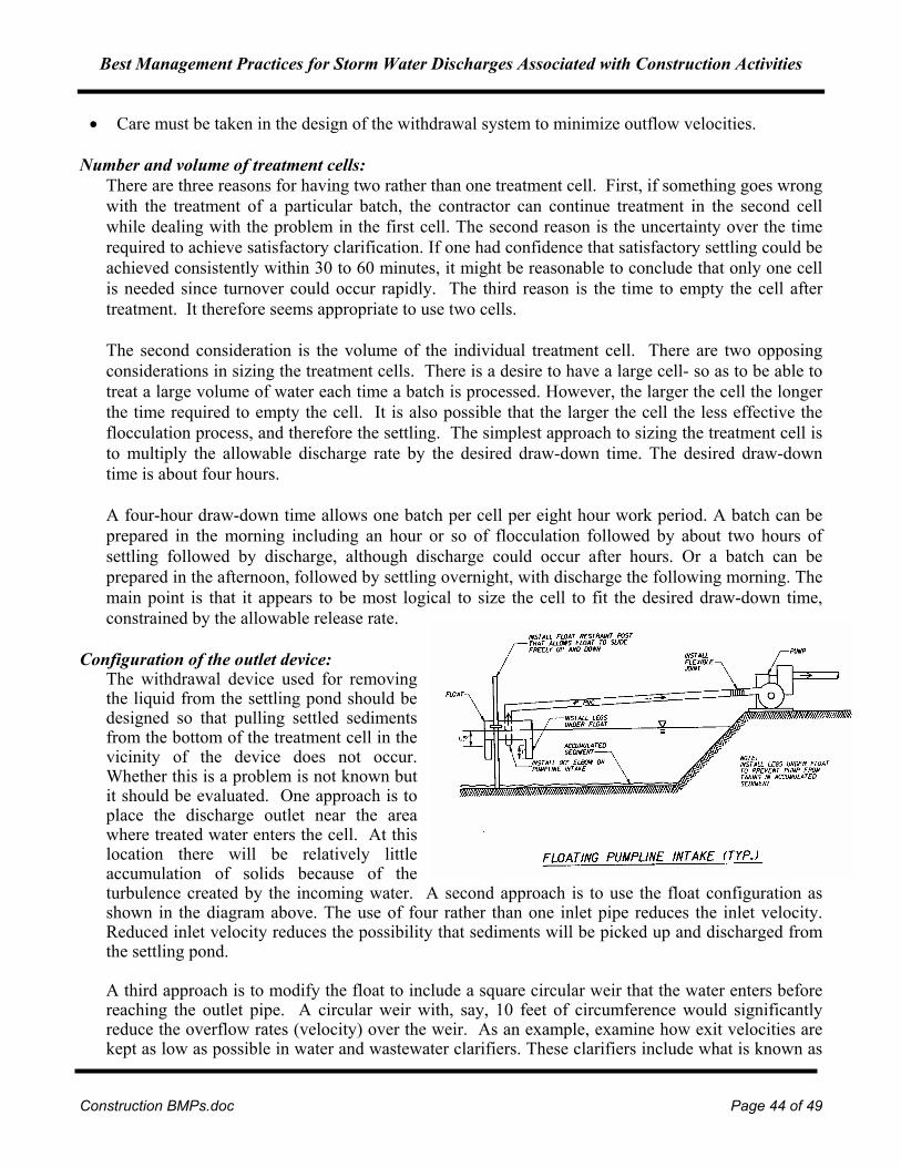
Best Management Practices for Storm Water Discharges Associated with Construction Activities
Construction BMPs.doc Page 44 of 49
• Care must be taken in the design of the withdrawal system to minimize outflow velocities.
Number and volume of treatment cells: There are three reasons for having two rather than one treatment cell. First, if something goes wrong with the treatment of a particular batch, the contractor can continue treatment in the second cell while dealing with the problem in the first cell. The second reason is the uncertainty over the time required to achieve satisfactory clarification. If one had confidence that satisfactory settling could be achieved consistently within 30 to 60 minutes, it might be reasonable to conclude that only one cell is needed since turnover could occur rapidly. The third reason is the time to empty the cell after treatment. It therefore seems appropriate to use two cells. The second consideration is the volume of the individual treatment cell. There are two opposing considerations in sizing the treatment cells. There is a desire to have a large cell- so as to be able to treat a large volume of water each time a batch is processed. However, the larger the cell the longer the time required to empty the cell. It is also possible that the larger the cell the less effective the flocculation process, and therefore the settling. The simplest approach to sizing the treatment cell is to multiply the allowable discharge rate by the desired draw-down time. The desired draw-down time is about four hours. A four-hour draw-down time allows one batch per cell per eight hour work period. A batch can be prepared in the morning including an hour or so of flocculation followed by about two hours of settling followed by discharge, although discharge could occur after hours. Or a batch can be prepared in the afternoon, followed by settling overnight, with discharge the following morning. The main point is that it appears to be most logical to size the cell to fit the desired draw-down time, constrained by the allowable release rate.
Configuration of the outlet device: The withdrawal device used for removing the liquid from the settling pond should be designed so that pulling settled sediments from the bottom of the treatment cell in the vicinity of the device does not occur. Whether this is a problem is not known but it should be evaluated. One approach is to place the discharge outlet near the area where treated water enters the cell. At this location there will be relatively little accumulation of solids because of the turbulence created by the incoming water. A second approach is to use the float configuration as shown in the diagram above. The use of four rather than one inlet pipe reduces the inlet velocity. Reduced inlet velocity reduces the possibility that sediments will be picked up and discharged from the settling pond. A third approach is to modify the float to include a square circular weir that the water enters before reaching the outlet pipe. A circular weir with, say, 10 feet of circumference would significantly reduce the overflow rates (velocity) over the weir. As an example, examine how exit velocities are kept as low as possible in water and wastewater clarifiers. These clarifiers include what is known as

Best Management Practices for Storm Water Discharges Associated with Construction Activities
Construction BMPs.doc Page 45 of 49
effluent launders. They are long troughs, placed at the outlet end the clarifier or around the outside circumference in the case of circular clarifiers, into which the water flows. Weirs reduce the exit velocity of the water leaving the clarification area of the clarifier. The weir may provide at least one and possibly two benefits with the treatment of storm water. First, it may reduce the carry-out of floc that is still settling while the cell is being drawn down, could result in lower final effluent turbidities and/or allow a reduction in the settling time to achieve the same effluent turbidity. Secondly, the weir could reduce if not eliminate the tendency for the withdrawal pipe to suck-up previously settled sediment. FLOCCULATION SYSTEMS SHOULD BE DESIGNED BY KNOWLEDGEABLE PERSONNEL. A CONSULTANT SHOULD BE CONTRACTED TO DEVELOP AND IMPLEMENT A SYSTEM. OPERATING PERSONNEL NEED TO BE SPECIFICALLY TRAINED TO OPERATE THESE SYSTEMS.
Efficiency: Mean turbidity reductions can be achieved in the 95.5% to 99.4% range using a flocculation system.
Direct Soil Application of Flocculant: As an alternative to an extensive flocculation system, a polyacrylamide (PAM) could be applied to the bare soil surface to bind the soil particles together and minimize erosion, as well as promoting infiltration. PAMs are long chains of polymers synthesized from natural gas. Until recently, PAM has been used most frequently on agricultural land as a soil conditioner, but its use has expanded to include construction sites and industrial water treatment. Since it is a flocculant, it may cause silt deposition when it comes in contact with sediment laden waters downstream from the site. For this reason, runoff should be collected and treated to remove the chemical before releasing it from the site. The City of Redmond, Washington has successfully tested this method on at least 2 construction sites of 3,000 square feet of clay soils. The PAM was applied at a rate of three pounds per acre, a level that was determined to be environmentally non-toxic, and spread dry with a hand held fertilizer spreader. The City of Redmond recommends that periodic bioassays be performed to confirm the absence of toxicity.
Efficiency: Left undisturbed, the compound proved to effectively work to reduce erosion for up to 6 weeks. However as soon as human or vehicular traffic disturbed the soil, the PAM needed to be reapplied. Redmond found that suspended solids in the water running off from the sites were reduced 67-84 %. Turbidity still remained fairly high, from 264-364 NTU, a reduction of 67-76%.
BMP #34 – ElectroFloc Description: Experiments with a process, tentatively called ElectroFloc indicates that it may be possible to use
electricity to floc dissolved metals, TSS, and turbidity from storm water runoff. By charging aluminum plates with about 40 volts DC in a batch process, it has been shown to create an approximately equal number of charged particles in suspension. These dissimilarly charged particles attract each other and due to aluminum ions present remain in contact with each other in as little as five minutes per liter. This works for TSS and turbidity in the lab and should work for dissolved metals as the metals usually are not really dissolved but submicron in size. Dissolved oxygen is increased in the water due to the splitting of the water molecule into hydrogen and oxygen
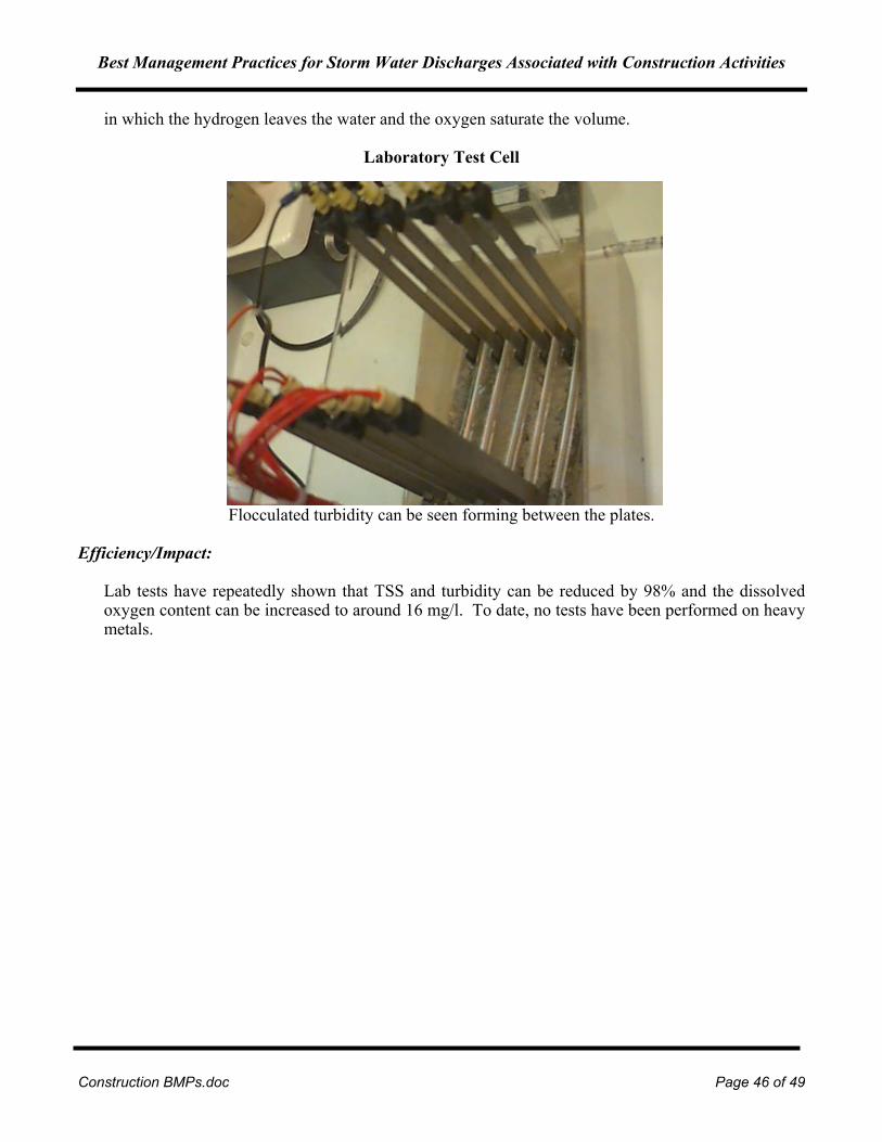
Best Management Practices for Storm Water Discharges Associated with Construction Activities
Construction BMPs.doc Page 46 of 49
in which the hydrogen leaves the water and the oxygen saturate the volume.
Laboratory Test Cell
Flocculated turbidity can be seen forming between the plates. Efficiency/Impact:
Lab tests have repeatedly shown that TSS and turbidity can be reduced by 98% and the dissolved oxygen content can be increased to around 16 mg/l. To date, no tests have been performed on heavy metals.

Best Management Practices for Storm Water Discharges Associated with Construction Activities
Construction BMPs.doc Page 47 of 49
REFERENCES
1. California Straw Works. (1999). “Straw Wattles.” [On-line]. Available: http://www.strawwattles.com. 2. Clark County Home Builders Association. (1998). “A Builder’s Guide to Erosion Prevention and
Sedimentation Control.” 3. Cluer, M.G. (1999). “Bioswales.” University of Washington. [On-line]. Available:
http://weber.u.washington/~mgcluer/bioswales.html 4. Goff, K. (1999). “Fugitive dust”. Erosion Control. 3, 86-95. 5. Gullywasher. (1999). “Catch Basin Inserts.” [On-line]. Available: http://www.gullywasher.com. 6. Fifield, J.S. (1999). “Using continuous berms to control sediment from disturbed lands.” Presented at
1995 SWCS Conference, Des Moines, Iowa. [On-line]. Available: http://www.mbw.com/cbmtech.html. 7. Kostielney, J.L. (1999). “Just because it’s temporary doesn’t mean it’s bad”. Erosion Control. 5, 66-
75. 8. Leeds, R., L.C. Brown, M.R. Sulc, L. VanLieshout. (1999). “Vegetated Filter Strip: Application,
Installation & Maintenance.” Ohio State University Extension Fact Sheet AEX-467-94. [On-line]. Available: http://ohioline.ag.ohio-state.edu/aex-fact/0467.html.
9. Mat, Inc. (1999). Soil Guard. [On-line]. Available: http://www.soilguard.com. 10. Minton, G. (1999). “Use of Polymers to Treat Construction Site Storm water”. Resource Planning
Associates. [On-line]. Available: http://www.ieca.org 11. New Hampshire Department of Environmental Services. (1999). “Soil Erosion and Sediment
Control on Construction Sites.” Environmental Fact Sheet WD-WEB-12. [On-line]. Available: http://www.des.state.nh.us/web-12.htm.
12. Nighman, D.M. (1999). “Infiltration practices for flood control”. Land and Water. 2, 13-15. 13. Norman, D.K., P.J. Wampler, A.H. Throop, E.F. Schnitzer & J.M. Roloff. (1988). “Best
Management Practices for Reclaiming Surface Mines in Washington and Oregon.” Washington Division of Geology and Earth Resources and Oregon Department of Geology and Mineral Industries.
14. North Carolina State University Water, Soil & Hydro-Environmental Decision Support System.
(1999). “Best Management Practices for Nonpoint Source Pollution Control.” [On-line]. Available: http://www.h2osparc.wq.ncsu.edu/info/bmps.html.
15. Oklahoma State University Cooperative Extension Service. (1999). “Using vegetation for erosion
control on construction sites.” Extension Facts: F-1514. 16. Oregon Department of Environmental Quality. (1997). “Recommended Best Management Practices

Best Management Practices for Storm Water Discharges Associated with Construction Activities
Construction BMPs.doc Page 48 of 49
for Storm Water Discharges.” 17. Purdue University. (1999). “Terracing”. [On-line]. Available:
http://abe.www.ecn.purdue.edu/~agen521/epadir/erosion/terraces.html. 18. Resource Planning Associates with HoweConsult. (1999). “Polymer Assisted Clarification of Storm
water from Construction Sites.” Prepared for the City of Redmond, Washington. 19. Trinity County Resource Conservation District. (1999). “Excavated Sediment Traps”. [On-line].
Available: http://www.snowcrest.net/tcrcd/pt-sc-es.htm. 20. Unified Sewerage Agency. (1999). “Storm water Pollution Control Manual: Best Management
Practices for Businesses.” 21. University of California-Santa Barbara School of Science and Environmental Management. (1999).
“Bioswales”. [On-line]. Available: http://128.111.100.231/research/Group_Projects. 22. University of Nebraska-Lincoln. (1999). “Terrace systems for Nebraska”. [On-line]. Available:
http://www.ianr.unl.edu/pubs/soil/g750.htm. 23. Tennessee-Knoxville. (1986). “Soil erosion prevention and sediment control: reducing non-point
source water pollution on construction sites.” [On-line]. Available: http://www.engr.utk.edu/research/water/erosion/figure29.htm.
24. US Environmental Protection Agency. (1999). “Management measure for vegetated treatment
systems.” [On-line]. Available: http://www.epa.gov/OWOW/NPS/MMGI/Chapter7/Ch7-2c.html. 25. W&H Pacific with CH2M-HILL. (1993). “Demonstration Project Using Yard Debris Compost for
Erosion Control.” Presented to Metropolitan Service District. 26. Metro. (June 1994). “Summary of Projects Using Yard Debris Compost for Erosion Prevention and
Control.” Solid Waste Department, Planning Department, 600 NE Grand Ave., Portland, OR 97232-2736, (503) 797-1695.
27. Glacier Northwest Inc., 1050 N. River Street, Portland, OR 97227-1719, Doug Hale (503) 335-2600. 28. Crop Science Society of America, Crop Science, Vol. 38 No. 4 July-August, 1968, pages 1042-1045,
“Erosion of Natural and Man-Made Erosion Control Materials” 29. San Diego State University Soil Erosion Research Laboratory, SDSU/SERL Project Reference No.
2000-01-SD, November 22, 2000, “Results from a Study of the Soil Dynamics, Inc. EssentialSoilTM Formulation: Runoff Characteristics and Sediment Retention Under Simulated Rainfall Conditions”
30. BioCycle Magazine, January 2001, “Compost Filter Berms and Blankets Take on the Silt Fence” 31. Journal of Soil & Water Conservation, Spring Issue, 2000, “Are Green Lots Worth More Than

Best Management Practices for Storm Water Discharges Associated with Construction Activities
Construction BMPs.doc Page 49 of 49
Brown”, Martha Herzog and Jon Harbor, Department of Earth & Atmospheric Services, Purdue University.
32. DriWater, http://www.driwater.com