Embed Size (px)
Citation preview

INTELLIGENTEFFICIENTFEEDING
FEEDING TECHNOLOGIES
E F F I C I E N T
F E E D I N G

Experts in Feeding Technology
2
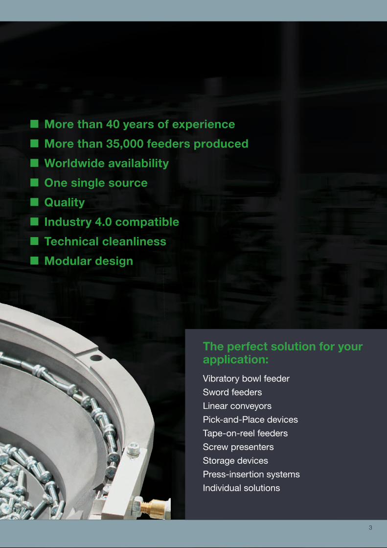
More than 40 years of experience
More than 35,000 feeders produced
Worldwide availability
One single source
Quality
Industry 4.0 compatible
Technical cleanliness
Modular design
The perfect solution for your application:
Vibratory bowl feeder
Sword feeders
Linear conveyors
Pick-and-Place devices
Tape-on-reel feeders
Screw presenters
Storage devices
Press-insertion systems
Individual solutions
3

International availability and service guaranteed!
We have a network of exclusive partners in every essential industrial country of the world and are always close at hand for our globally operating clients. Our customers benefit from the entire technical knowledge of our experts in addition to the regionalexperience of our local representatives. Solutions are successfully developed and then quickly and reliably passed on through our worldwide production locations.
DEPRAG headquarters in Germany
DEPRAG Inc., USA
DEPRAG CZ a.s., Czech Republic
Worldwide Availability
4

DEPRAG Assembly Technologies Co., Ltd., China
DEPRAG headquarters in Germany
DEPRAG subsidiaries
DEPRAG sales partners
5

In-house developed and manufactured!
Your end-to-end solution: application consultancy, operator training, fully developed system components, screwdrivers, feeders, controllers and process monitoring. All components are designed to be compatible with each other and have been tried and tested over many years.
One Single Source
6
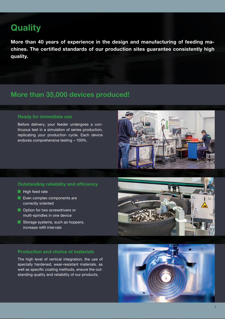
More than 40 years of experience in the design and manufacturing of feeding ma-chines. The certified standards of our production sites guarantee consistently high quality.
Ready for immediate use
Before delivery, your feeder undergoes a con-tinuous test in a simulation of series production, replicating your production cycle. Each device endures comprehensive testing – 100%.
Outstanding reliability and efficiency
High feed rate
Even complex components are correctly oriented
Option for two screwdrivers or multi-spindles in one device
Storage systems, such as hoppers, increase refill intervals
Production and choice of materials
The high level of vertical integration, the use of specially hardened, wear-resistant materials, as well as specific coating methods, ensure the out-standing quality and reliability of our products.
More than 35,000 devices produced!
Quality
7

Industry 4.0 Compatible
Feeding 4.0
PFCi100 integrated functions
External master IPC (e.g., DPU100) is the operating platform
External control and communication
Bus interface
Parameter adjustment via IPC (DPU100)
Communication via TCP/IP
Programming via an integrated web browser
DPU setting options
Frequency
Amplitude
Acceleration-rate
Soft-start
Waveform
Operating platform DPU
The DPU (DEPRAG Processing Unit) is exceptionally user-friendly. Settings can be performed on the touchscreen by using the provided slide-bars.
We fulfill your requirements for intelligent integrated components with the innovative controller PFCi100; this allows remote control, documentation, and interaction with the DEPRAG feeding machines. Your device can be monitored and controlled at any time, from anywhere in the World.
8
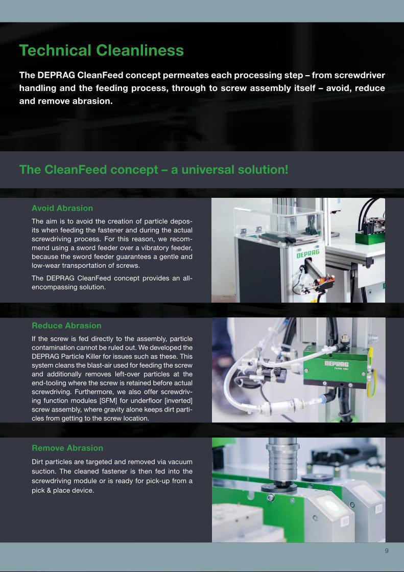
Technical Cleanliness
Avoid Abrasion
The aim is to avoid the creation of particle depos-its when feeding the fastener and during the actual screwdriving process. For this reason, we recom-mend using a sword feeder over a vibratory feeder, because the sword feeder guarantees a gentle and low-wear transportation of screws.
The DEPRAG CleanFeed concept provides an all-encompassing solution.
The CleanFeed concept – a universal solution!
Remove Abrasion
Dirt particles are targeted and removed via vacuum suction. The cleaned fastener is then fed into the screwdriving module or is ready for pick-up from a pick & place device.
Reduce Abrasion
If the screw is fed directly to the assembly, particle contamination cannot be ruled out. We developed the DEPRAG Particle Killer for issues such as these. This system cleans the blast-air used for feeding the screw and additionally removes left-over particles at the end-tooling where the screw is retained before actual screwdriving. Furthermore, we also offer screwdriv-ing function modules [SFM] for underfloor [inverted] screw assembly, where gravity alone keeps dirt parti-cles from getting to the screw location.
The DEPRAG CleanFeed concept permeates each processing step – from screwdriver handling and the feeding process, through to screw assembly itself – avoid, reduce and remove abrasion.
9

Handheld Applications
In the development of your assembly machine, we turn to components from our comprehensive, coordinated, and modular product line – resulting into a fast availa-bility, efficiency, tried and tested functionality, and continuous improvement.Configuration over construction!
100 % compatible
No interfa
ce is
sues
Modular Design
10

Stationary Applications
100 % compatible
No interfa
ce is
sues
11
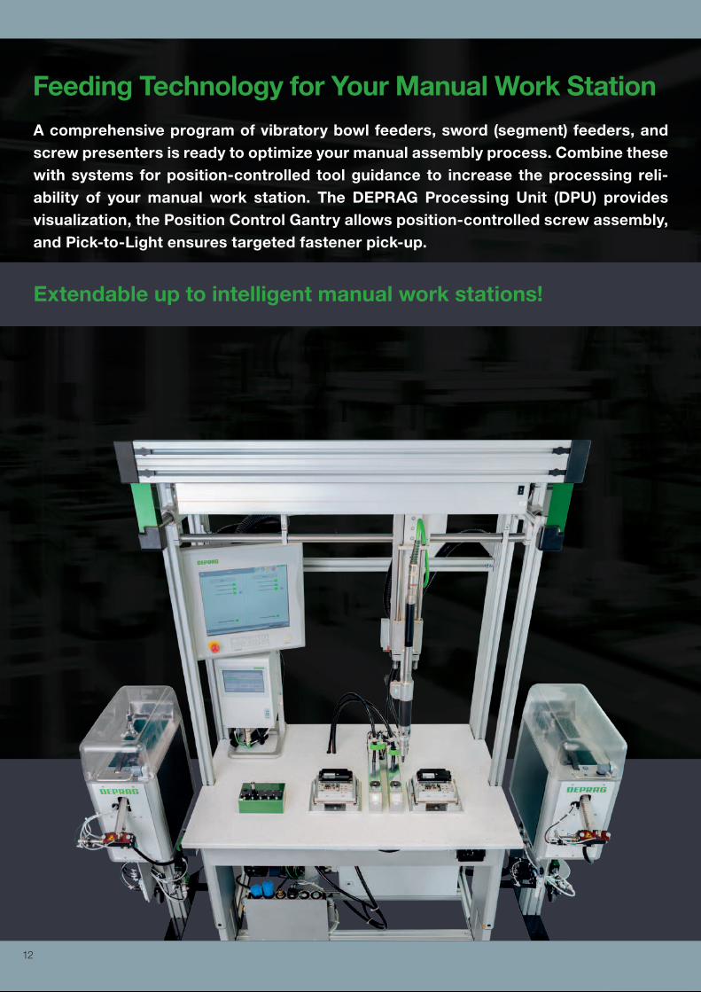
Feeding Technology for Your Manual Work Station
Extendable up to intelligent manual work stations!
A comprehensive program of vibratory bowl feeders, sword (segment) feeders, and screw presenters is ready to optimize your manual assembly process. Combine these with systems for position-controlled tool guidance to increase the processing reli-ability of your manual work station. The DEPRAG Processing Unit (DPU) provides visualization, the Position Control Gantry allows position-controlled screw assembly, and Pick-to-Light ensures targeted fastener pick-up.
12

Feeding Technology for Your Stationary Application
100 % reliability ► productivity + system uptime!
Our feeding systems have been designed for the reliable supply of fasteners to en-able outstanding accuracy and productivity of your assembly system. Integration into your control system is particularly convenient and straightforward. Our feeder line includes vibratory bowl feeders, sword (segment) feeders, linear conveyors, storage systems, tape-on-reel feeders and screw presenters.
13

Vibratory Feeder – eacy feed
The new generation vibratory feeder!
The vibratory feeder is our most utilized feeding device. The eacy feed system com-bines the ideal fundamentals for sustainable production of the future: energy, efficiency, and intelligent communication.
14

Approx. 80 % energy savings
The revolutionary controller and the new drive pro-vide the exceptional energy efficiency of the eacy feed.
24 V oscillating magnets achieve significantly re-duced power consumption, meaning an energy sav-ing of approx. 80 %.
Intelligent communication
The revolutionary controller allows remote control and communication.
The eacy feed is accessible from anywhere in the World via TCP/IP.
All settings can be displayed and adjusted at any time.
The eacy feed devices are particularly well-suited for Industry 4.0 systems.
Reduced consumption, increased flexibility
The revolutionary controller allows for approx. 80 % less power consumption.
The new controller and vibratory drive are based on 24 V/DC operating voltage.
Universal power supply (115 V – 230 V).
Independent to local AC frequency.
One design for all markets.
Perfect vibration intensity
An acceleration sensor is mounted on the vibratory drive to monitor and regulate vibration intensity, en-suring that output remains stable and consistent, in-dependent from all fill-levels.
No need for readjustments.
Maintains ideal vibration behavior and minimizes wear and tear on the materials.
Simplifies refill procedures & supports all bowl sizes.
For any application
The eacy feed system is available in four fill sizes:0.15-, 0.75-, 1.2-, and 2.5-liter capacity - both in single and double spiral design.
A large variety of components can be processed by the eacy feed system: screws, nuts, threaded pins, o-rings, cleanroom parts, and many more!
Standard feeders are adaptable to your specific in-stallation environment for integration into individually customized assembly systems.
15

Sword Feeder
Technical cleanliness!
Sword feeders or segment feeders are particularly suitable for use in cleanroom en-vironments. One advantage of the sword feeder is the very gentle, low abrasion part feeding.
16

Efficient production
The high level of vertical integration, the use of spe-cially hardened, wear-resistant materials, as well as specific coating methods, ensure the outstanding quality, reliability, and efficiency of the sword feeder.
Customized design
If you need to integrate a feeding system into an ap-plication with challenging dimensional conditions, we can adapt our standard devices to fit your oper-ating environment.
Correctly oriented sorting
The parts in the supply bin are scooped up into a seg-mented rail by a tilting motion. The parts slide along this rail through mechanical- and directional compo-nents and arrive correctly sorted in the storage rail.
Self-regulated feed intensity
A sensor in the storage rail regulates the number of stroke movements required. The required fasteners are perfectly timed and positioned ready for assem-bly.
Low noise level
The production operators favor the low noise-level of the sword feeder. Due to the specially designed separator and the adapted controller sequence, the sword feeders are especially quiet.
17
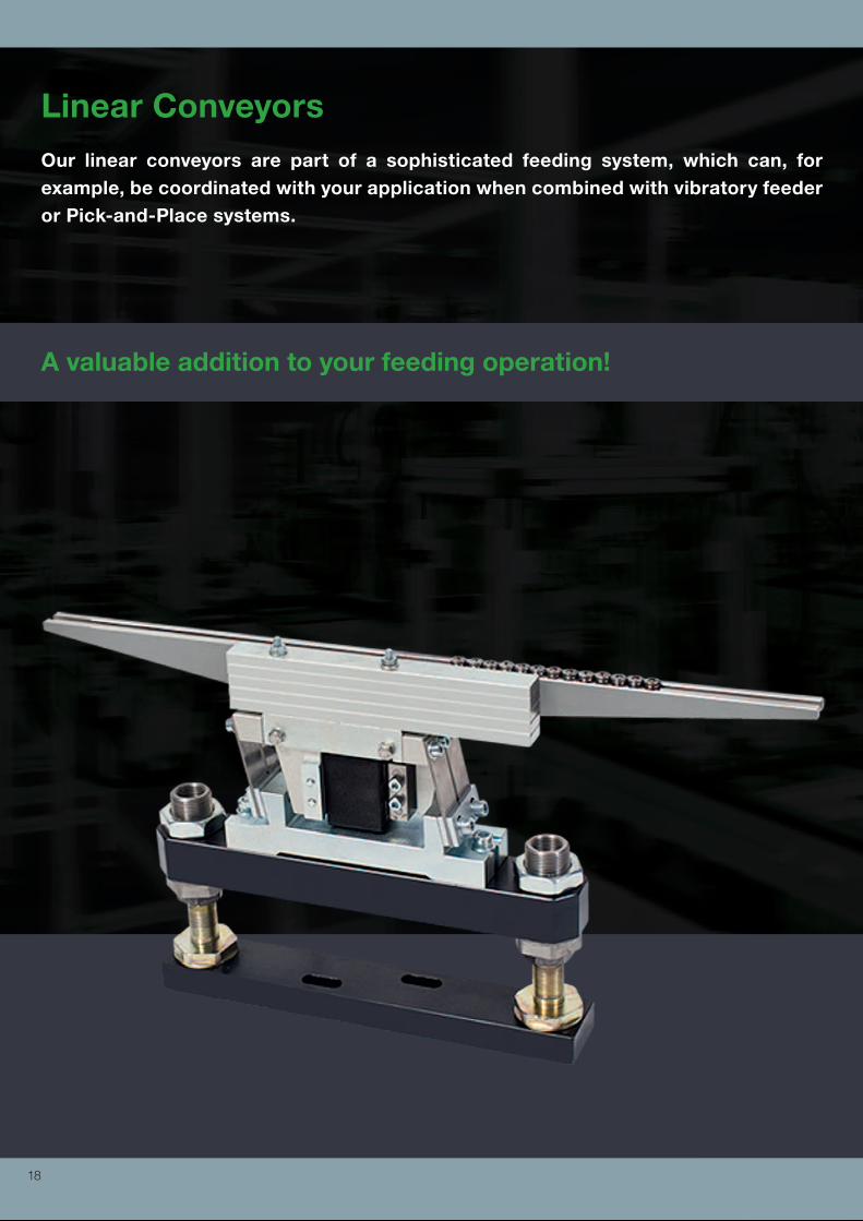
Linear Conveyors Our linear conveyors are part of a sophisticated feeding system, which can, for example, be coordinated with your application when combined with vibratory feeder or Pick-and-Place systems.
A valuable addition to your feeding operation!
18
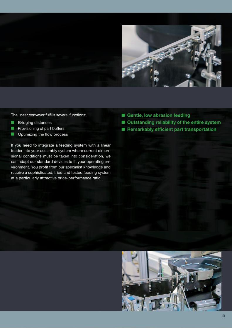
The linear conveyor fulfills several functions:
Bridging distances
Provisioning of part buffers
Optimizing the flow process
If you need to integrate a feeding system with a linear feeder into your assembly system where current dimen-sional conditions must be taken into consideration, we can adapt our standard devices to fit your operating en-vironment. You profit from our specialist knowledge and receive a sophisticated, tried and tested feeding system at a particularly attractive price-performance ratio.
Gentle, low abrasion feeding
Outstanding reliability of the entire system
Remarkably efficient part transportation
19

Pick-and-Place Method Feeding to a Pick-and-Place position is often the most attractive solution for screws with very short shafts, rivets with large collar diameters, and parts with complex external geometries.
The alternative to feeding through a hose – independent from the part’s geometry!
20

For stationary applications, either vacuum technology or grippers are predominately used on Pick & Place de-vices. The release- and reload procedure, is controlled by a PLC using sensor monitoring.
For handheld applications, we recommend utilizing a vacuum procedure or pick-up by a magnetic tool. A presence sensor, integrated into the pick-up receptacle, generates a reload signal when the part is released and automatically prepares the next one.
Accurate, reliable part positioning
When using the Pick-and-Place method parts are accurately and reliably placed in the assembly posi-tion.
21

Tape-on-reel feeding technology uses a tape reel insert-
ed in a rolling receptacle. The unwinder pulls the tape
until the next component is in the detached position.
Once the sensor detects that the piece has reached the
detached position, a downholder secures and holds the
tape. Once the pick-up tooling (e.g., a vacuum gripper)
is ready to proceed (i.e., vacuum suction ON), the slide
carriage moves back, and the tape is pulled past the car-
riage blade.
Tape-on-Reel FeedingDEPRAG tape-on-reel feeders are used to process components that are loaded on single- and/or double- sided adhesive tape reels.
Precise and reliable supply of components!
The components are loosened from the tape and are
now ready for processing. Once the pick-up tooling
has moved away from the pick-up position, the holder
retracts, the slide carriage runs forward again, and the
winder moves the next component on the tape reel into
the pick-up position.
22
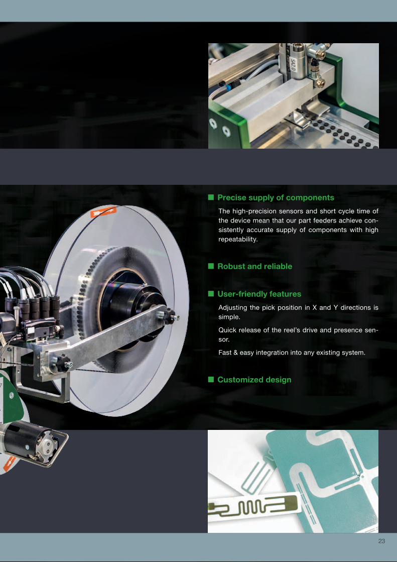
Precise supply of components
The high-precision sensors and short cycle time of the device mean that our part feeders achieve con-sistently accurate supply of components with high repeatability.
Robust and reliable
User-friendly features
Adjusting the pick position in X and Y directions is simple.
Quick release of the reel’s drive and presence sen-sor.
Fast & easy integration into any existing system.
Customized design
23

Screw PresentersScrew presenters are particularly suitable for the automated supply of screws, both in preparation for manual pick-up and stationary integrated screwdrivers. Are you looking to automate your assembly? Screw presenters are a fast, cost-effective solu-tion…
User-friendly
Secure, fast pick-up of supplied screws using mag-netic bit or vacuum.
...for assembly of small production batches!
Gentle & quiet feeding
Screw feeding via two lift segments in the screw bin, enabling gentle & quiet feeding. Screws fall onto a vi-brating guide rail and are then brushed into the cor-rect position and transported onwards.
Stand-alone operation
The integrated controller in the device enables stand-alone operation.
Screw supply is accurate and reliable due to the regulated sequence controller using light barrier and microswitch.
Compact design
If required, several DEPRAG screw presenter can be arranged even into confined workspaces due to its compact design.
Special solutions on request
24

Storage SystemsSignificantly decrease the number of refills by adding a storage system to your feeder.
Optimize processing by maintaining a constant fill level – No need to adjust the feed rate!
Gentle component handling
Gentle component handling minimizes the waiting time of feed parts in the vibratory system.
Flexible
No need for costly modifications when using a vari-ety of feeders. The hopper outlet is adjustable to the size of the component. Additional regulating possi-bilities allow the hopper to be adjustable into two dif-ferent directions.
Low noise and wear-resistant
The outflow-chute is enclosed, resulting into a sub-stantial reduction in noise.
Noise-barriers are available as a special accessory for all vibratory feeders; they are specifically de-signed for use together with a hopper.
Simple operation and easy set-up
The DEPRAG hoppers come with a 24-volt gear mo-tor. They can be operated merely via an output on the higher-level PLC.
25

Screws
A vibratory feeder or a sword feeder can be used for the processing of screws, depending on screw size. Our screw presenter is ideal for the first step in screw supply automation.
Material to Be ConveyedScrews or o-rings, nuts or threaded pins, rivets or balls: Different components and fasteners require different feeding methods. Special provisions come into play for applications requiring technical cleanliness and for sensitive parts requiring particu-larly gentle handling.
MATERIAL
Threaded pins
A vibratory feeder is most suited to the pro-cessing of threaded pins. There are handheld and stationary options for the processing of threaded pins.
Nuts
A vibratory feeder is well-suited for the pro-cessing of nuts. There are handheld and sta-tionary solutions for the presentation of nuts.
Press-insertion components
We supply standardized press-insertion sys-tems, consisting of a press-in device that is combined with a vibratory or sword feeder, to process rivets, pins, sleeves, and balls.
26

CONVEYED
Small parts on backing film
Small parts attached to a backing film on a tape-reel needing to be picked-up by vacuum or gripper, can be processed by a DEPRAG tape-on-reel feeder. It is even possible to pro-cess components on both single- and double-sided adhesive tapes.
Labels, etc.
The DEPRAG tape-on-reel feeder predomi-nately retrieves labels, stickers, and a protec-tive film arriving on a tape-reel, by utilizing vacuum assistance.
Different components
Wide-ranging component designs can be pro-cessed using a vibratory feeder in combination with a linear-conveyor system. We can utilize sensors so that the most varied of component geometries can be processed, particularly in stationary feeding systems.
O-Rings
A vibratory feeder is the best-suited device for the processing of O-rings into an assembly so-lution. In a stationary application: The O-ring is supplied to a pick-up position, stretched and assembled.
27

Feedability Criteria for Screws1. Analysis of screw geometry
The screw geometry decisively influences the selec-tion of the appropriate feeding technology. Automated feeding using a feed hose is suitable for all shaft-heavy screws with a circular head which fulfill the criteria in image 1.
The approximation formula is used to determine that screws cannot reliably be fed through a hose if the an-gle a is less than 30° or the ratio of diameter D to shaft length L is less than 0.866.
2. Screw quality
The reliability of feeding depends on the quality of the screws. Your processing-reliability specifications determine the screw’s required quality level. The degree of purity de-fines the quality level; for example, a degree of purity of 10 ppm (“parts per million”), means that in 100,000 screws there is only one defective part, which may cause the feeder to malfunction.
3. Which feeding principle is most suited to your application?
The vibratory feeder is particularly well-suited for screws with tricky dimensions or if there are high demands on the feed rate. The sword feeder is more suitable where gentle handling or quiet feeding is required. If feeding via feed hose is not an option, a Pick-and-Place method can be used.
Image 1: Criteria and parameters for the feedability of screws.
d = feed hose IDD = screw head-ØL = shaft length
Image 2: Example of standard nosepieces.
Image 3: Tiltable mouthpiece for the feeding of very short screws.
Ball-typenosepiece
Split-type nosepiece
A = D + 2.5 mmB = A + D - d
n = A x B n = ø B
B = 3D - 2d + 5 mm
D = screw head-Ød = shaft-Øn = space required to open
feedability criteria:a > 30°
d ~ D + 0.5 mm
approximation formula:L > D + 2 mm
28

4. Tooling selection
At the end of the mouthpiece, there are so-called guid-ing jaws (split-type nosepiece) or sleeves (ball-type nosepiece), designed to support and position the screw (image 2).When working with very short screws or applications where a socket is used, tiltable or active mouthpieces are utilized (image 3).
Image 4: Screw templates simplify precise positioning of the screw and the accessibility of the guiding jaws or sleeves.
Image 5: When adapting to a customer’s template, the dimension H is required to select the correct screwdriver stroke.
5. Accessing the work piece
The physical accessibility of a workpiece is an essen-tial consideration for the effective implementation of handheld screw feeders. Clear space around the screw head is required for the use of a ball-type- or split-type nosepiece or a vacuum finder. Flat surfaces simplify ac-cessing the screw-location and reduce the downforce needed to activate the tool. If the geometry of the screw location does not allow precise positioning or the open-ing of a locking jaw, then a screw template is recom-mended (images 4 and 5).
Even curved surfaces with recessed screw-locations can be securely accessed. Using a screw template with handheld assemblies can significantly reduce the cycle time for workpieces having multiple screw-positions.
Nosepiece
Screw template
Component A
Component B
29
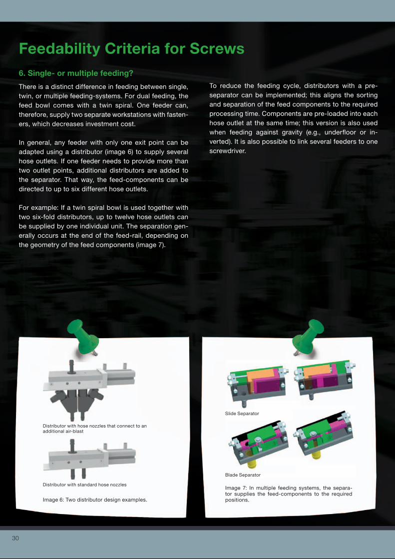
Feedability Criteria for Screws6. Single- or multiple feeding?
There is a distinct difference in feeding between single, twin, or multiple feeding-systems. For dual feeding, the feed bowl comes with a twin spiral. One feeder can, therefore, supply two separate workstations with fasten-ers, which decreases investment cost.
In general, any feeder with only one exit point can be adapted using a distributor (image 6) to supply several hose outlets. If one feeder needs to provide more than two outlet points, additional distributors are added to the separator. That way, the feed-components can be directed to up to six different hose outlets.
For example: If a twin spiral bowl is used together with two six-fold distributors, up to twelve hose outlets can be supplied by one individual unit. The separation gen-erally occurs at the end of the feed-rail, depending on the geometry of the feed components (image 7).
To reduce the feeding cycle, distributors with a pre-separator can be implemented; this aligns the sorting and separation of the feed components to the required processing time. Components are pre-loaded into each hose outlet at the same time; this version is also used when feeding against gravity (e.g., underfloor or in-verted). It is also possible to link several feeders to one screwdriver.
Image 6: Two distributor design examples.
Image 7: In multiple feeding systems, the separa-tor supplies the feed-components to the required positions.
Slide Separator
Blade Separator
Distributor with hose nozzles that connect to an additional air-blast
Distributor with standard hose nozzles
30
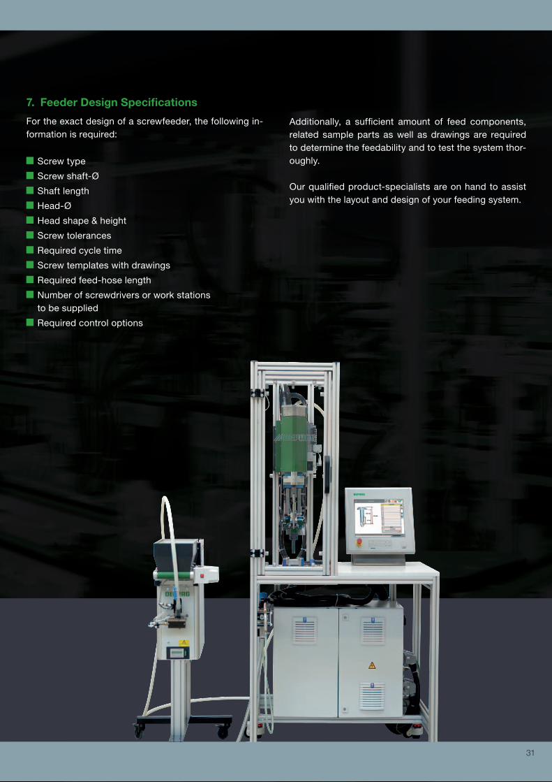
7. Feeder Design Specifications
For the exact design of a screwfeeder, the following in-formation is required:
Screw type
Screw shaft-Ø
Shaft length
Head-Ø
Head shape & height
Screw tolerances
Required cycle time
Screw templates with drawings
Required feed-hose length
Number of screwdrivers or work stations to be supplied
Required control options
Additionally, a sufficient amount of feed components, related sample parts as well as drawings are required to determine the feedability and to test the system thor-oughly.
Our qualified product-specialists are on hand to assist you with the layout and design of your feeding system.
31

More information: www.deprag.com
D38
10E
10.
2018
Your global partner forscrewdriving technology, feedingtechnology and automation


![DEPRAG SCHULZ GMBH u. CO€¦ · Thread Friction coefficient µ total Max. preload force FM max. [N] Max. tightening torque MA max. [Ncm] Strength class in accordance with iSo 898/1](https://img.pdfslide.us/doc/110x75/606a7386aaac1812881aa19b/deprag-schulz-gmbh-u-co-thread-friction-coefficient-total-max-preload-force.jpg)