Embed Size (px)
Citation preview

DDEEPPAARRTTMMEENNTT OOFF
EELLEECCTTRRIICCAALL AANNDD EELLEECCTTRROONNIICCSS
EENNGGIINNEEEERRIINNGG
LLAABBOORRAATTOORRYY MMAANNUUAALL
SSUUBBJJEECCTT CCOODDEE :: BBEEEE11LL11
SSUUBBJJEECCTT NNAAMMEE :: BBAASSIICC EELLEECCTTRRIICCAALL AANNDD
EELLEECCTTRROONNIICCSS EENNGGIINNEEEERRIINNGG
LLAABBOORRAATTOORRYY

LLEEAARRNNIINNGG OOUUTTCCOOMMEESS
Students will able to handle basic electrical and electronics equipment’s.
Students will able to do staircase wiring.
Students will able to understand domestic wiring procedures practically.
Student will able to assemble electronic systems.
Students will understand all the fundamental concepts involving electrical
Engineering.
Students will understand all the fundamental concepts involving electronics
Engineering.
I LIST OF EXPERIMENTS FOR ELECTRICAL ENGINEERING LAB
1. Fluorescent lamp wiring
2. Stair case wiring
3. Measurement of electrical quantities-voltage current, power & power factor in RLC circuit
4. Residential house wiring using fuse, switch, indicator, lamp and energy meter
5. Measurement of energy using single phase energy meter
6. Measurement of resistance to earth of electrical equipment
II LIST OF EXPERIMENTS FOR ELECTRONICS ENGINEERING LAB
1. Study of electronic components and equipment’s.
a. Resistor Colour coding using digital multi-meter.
b. Assembling electronic components on bread board.
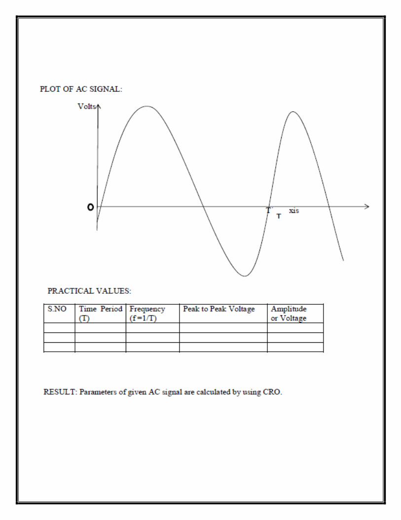
2. Measurement of ac signal parameters using cathode ray oscilloscope and function generator.
3. Soldering and desoldering practice.
4. Verification of logic gates (OR, AND, OR, NOT, NAND, EX-OR).
5. Implementation of half adder circuit using logic gates.

ELECTRICAL

ELECTRICAL ENGINEERING PRACTICE
INTRODUCTION
Electric power is supplied for commercial and residential use in three phases with a
neutral. Some of the low power consumption residential connections will have only a single
phase with a neutral. The single-phase AC supply is 230V but a three-phase supply is 440V.
SAFETY MEASURES
1. Use approved tools, equipment’s and protective devices.
2. Do not work under poor light or when you are tired.
3. Do not work in damp areas or in wet shoes or clothes.
4. Keep tools and equipment’s clean and in good working condition.
5. Read all instructions carefully before using the appliances.
6. To prevent electrical hazards, DO NOT immerse appliances in water or
Other liquids.
7. Always unplug an appliance before cleaning, or whenever it is not in use.
Ensure that you pull by the plug and not the cord.
8. DO NOT operate any appliance with a damaged cord or plug.
9. Always use an appliance on a dry, level surface.
10. Keep appliances away from heated surfaces and open flames.
11. Check the electric power supply from the switch position.
TOOLS USED IN WIRING
PLIERS
Pliers are used to cut wire and also to hold it. Pliers have an insulated handle. Long nose
pliers are used to hold wires in small space and also to tighten or loose small nuts.
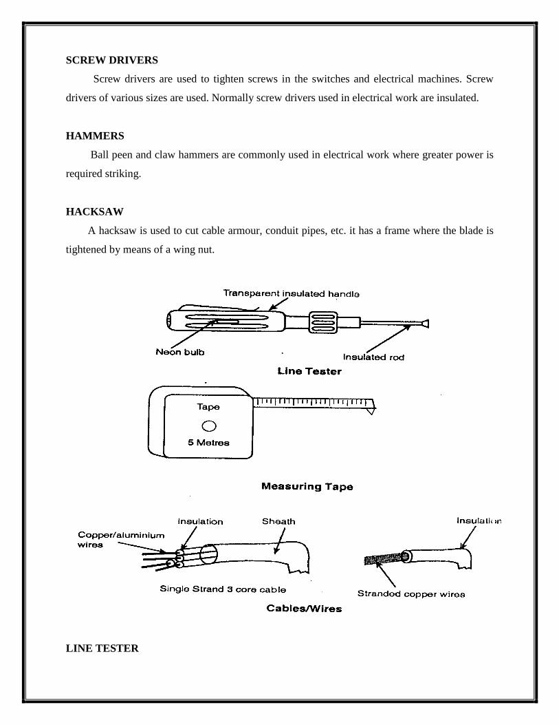
SCREW DRIVERS
Screw drivers are used to tighten screws in the switches and electrical machines. Screw
drivers of various sizes are used. Normally screw drivers used in electrical work are insulated.
HAMMERS
Ball peen and claw hammers are commonly used in electrical work where greater power is
required striking.
HACKSAW
A hacksaw is used to cut cable armour, conduit pipes, etc. it has a frame where the blade is
tightened by means of a wing nut.
LINE TESTER

A line tester is used to check the electric supply in the line or phase wire. It has a small neon
bulb which indicates the presence of power supply. It can also be used as a screw driver to
tighten small screws in switches.
MEASURING TAPE
A measuring tape is used to measure the length of the wire and also to mark the positions of
the switches and other electrical fittings.
WIRES
An electric wire is a copper or aluminum insulated wire and has one or more twisted stands.
Vulcanized Indian Rubber (VIR) wire, cotton flexible or rubber flexible wire and poly vinyl
chloride (PVC) wires are commonly used in house wiring.
TYPES OF CIRCUIT
There are three types of circuits. They are
Open circuit
Closed circuit
Short circuit
OPEN CIRCUIT
If the switch used in the circuit is in ‘off’ position, then the circuit is said to be open circuit.
There will not be any flow of current in open circuit.

CLOSED CIRCUIT
If the switch used in the circuit is in ‘on’ position, then the circuit is said to be closed
circuit. There will be normal flow of current in closed circuit.
SHORT CIRCUIT
When the positive terminal and negative terminal of any circuit comes in contact and very
high current flows through the circuit, then it is called as short Electrical Circuit.
An electrical circuit should consist of the following.
An energy source is used to provide the voltage needed to force the current
Through the circuit.
Conductor is used through which the current can flow.
A load (resistor) is used to control the amount of current and to convert the Electrical
energy into other forms.
A control device (switch) is used to start or stop the flow of current.
TYPICAL LIGHTING CIRCUITS
House – wiring is as simple as one lamp is controlled by one switch or may be a special
requirement of controlling one lamp from two or more number Of places. Such type of

circuits is used for staircase, bedroom and corridor lighting Systems. The basic principle
involved in such circuits and the requirement of additional special accessories are
discussed below:
BEDROOM LIGHTING
A bedroom requires one lamp at the dressing table controlled by a switch and one lamp
just above the bed which may require dual control by two 2 way switches, one provided near the
entrance (door) and the other provided above the bed. The circuit which describes the lighting in
bedroom is as follows:
WIRING
WIRING METHODS
A circuit is a path along which the electric current flows from the negative Side of the
power source to the positive side. There are three types of electrical circuit.
(i) Series circuit
(ii) Parallel circuit
(iii) Combination of series and parallel circuit.
SERIES CIRCUIT
The series circuit provides a single, continuous path through which current flows. In this
the devices are connected one after another and the current flows through them until it returns to
the power source. The circuit is shown in fig. Hence, even when one device breaks down the
remaining devices will not operate because the circuit is broken.
PARALLEL CIRCUIT
In parallel circuit the devices are connected side by side so that, current flows in a number
of parallel path. The parallel circuit is shown in fig. In this type of circuit each device is
connected across the power source so that even if one device breaks down, the other devices
continue to operate. Hence this type of circuit is used in home wiring.

EXP NO: 1 FLUORESCENT LAMP WIRING
Aim:
To prepare wiring for a fluorescent tube light with switch control.
Tools Required:
1. Screw driver 2. Hammer 3. Pliers 4. Line tester
Components Required:
1. Switch 2. Tube light with fitting 3. Joint clips
4. Wires 5. Screws 6. Switch board
Working of the Fluorescent Tube Light:
The fluorescent lamp circuit consists of a choke, a starter, a fluorescent tube and a
frame. The length of the commonly used fluorescent tube is 100 cm; its power rating
is 40 W and 230V. The tube is filled with argon and a drop of mercury. When the
supply is switched on, the current heats the filaments and initiates emission of
electrons. After one or two seconds, the starter circuit opens and makes the choke to
induce a momentary high voltage surge across the two filaments. Ionization takes
place through argon and produces bright light.
Procedure:
1. Mark the switch and tube light location points and draw lines for wiring on the
wooden board.
2. Place wires along the lines and fix them with the help of clips.
3. Fix the switch and tube light fitting in the marked positions.
4. Complete the wiring as per the wiring diagram.
5. Test the working of the tube light by giving electric supply to the
Circuit.

CIRCUIT DIAGRAM - TUBE LIGHT
Result:
The wiring for the tube light is completed and tested.
FLUORESCENT TUBE FLUORESCENT TUBE
1 , 230V
50 Hz
AC
HOLDER
40 W, 230 V
FLUORESCENT TUBE
N P
HOLDER
CHOKE 1 - WAY
SWITCH
STARTER

EXP NO: 2 STAIR CASE WIRING
Aim:
To wire for a stair case arrangement using a two-way switch.
Tool Required:
1. Screw driver 2.Hammer 3.Pliers 4.Line tester
Components Required:
1. Two-way switches 2. Bulb holders 3. Bulbs
4. Joint clips 5. Wires 6. Screws
7. Ceiling rose and 8. Switch board
Procedure:
1. Mark switch and bulb location points and draw lines for wiring on the wooden Board.
2. Place wires along the lines and fix them with the help of clips.
3. Fix the two-way switches and bulb holder in the marked position on the wooden Board.
4. Complete the wiring as per the wiring diagram.
5. Test the working of the bulbs by giving electric supply to the circuit.
Theory:
A two switch is installed near the first step of the stairs. The other two way switch is
installed at the upper part where the stair ends. The light point is provided between first and last
stair at an adequate location and height if the lower switch switches on the light. The switch at
the top or vice versa can switch it off. Two number of two way switches are used for the
purpose. The supply is given to the switch at the short circuited terminals. The connection to the
light point is taken from the similar short circuited terminal of the second switch; other two
independent terminals of each circuit are connected through cables.

TABULATION
Result:
The staircase wiring is completed and tested.
SWITCH POSITION
LAMP
CONDITION
SWITCH- 1
SWITCH- 2
OFF OFF OFF
ON OFF ON
OFF ON ON
ON ON OFF
10 A P
CIRCUIT DIAGRAM --STAIRCASE WIRING
TWO WAY SWITCH- 2
N
FUSE
1 ,
230V
50 Hz
AC
60 Watts Lamp
TWO WAY SWITCH-1

EXP NO: 3 MEASUREMENT OF ELECTRLCAL QUANTITIES-VOLTAGE
CURRENT, POWER & POWER FACTOR IN RLC CIRCUIT
Aim:
To measure electrical quantities for the given single phase circuit.
Apparatus:
SL.NO Components
Required Range Type Quantity
1 Ammeter
(0-10)
MI
1
2 Load
Variable RLC 1
3 Volt meter
(0-300)
MI 1
4 Watt meter
300V, 10A UPF 1
5 Autotransformer
1KVA
230/(0-240) V
1PH 1
Formulas:
Apparent Power = VI (Voltmeter reading x Ammeter reading)
Real Power = VI Cos Ф (Watt meter reading)
Power factor (Cos Ф) = Real Power / Apparent Power
Indicated Power = Observed reading X Multiplying factor
% Error = (Indicated Power –Actual Power) x100 /Actual Power
Actual Power = Voltmeter reading x Ammeter reading x Power factor
%
E
R
R
O
R
CURRENT
MODEL GRAPH

D
P
S
T
S
W
I
T
C
H
(0-10A)MI
N
P
1
230V
50 Hz
AC
1 Auto Transformer
(230/0-240)V
(0-300V)MI VD
A
VD
M L
C V
C.C
P.C
FUSE
10A
300 V, 10 A, UPF
RLC
L
O
A
D
CIRCUIT DIAGRAM:
P.C -- Pressure Coil C.C --- Current Coil
MI – Moving Iron UPF – Unity Power Factor

TABULAR COLUMN:
S.NO
Volt meter
readings (Volts)
Ammeter
readings
(Amps)
Watt meter readings (Watts)
Power factor
Observed
reading
Indicated
reading
1.
2.
3.
4.
5.
Procedure:
1. Connections are given as per the circuit diagram
2. Set the rated voltage by adjusting Auto transformer
3. Observe the meter readings for various loading conditions.
4. Calculate the error and plot the graph between %error and current value.
Result:
Thus electrical quantities like Voltage, Current, Power and Power factor Values
Measured.

EXP NO. 4 RESIDENTIAL HOUSE WIRING USING FUSE, SWITCH,
INDICATOR, LAMP AND ENERGY METER.
Aim:
To prepare residential wiring using Fuse, Switch, Indicator, Lamp and Energy meter .
Apparatus Required:
SL.NO.
Components Required
Range
Quantity
1 One way Switch
---- 1
2 Energy Meter
1 Ph --
3 Indicator
----- 1
4 Lamp
---- 1
5
Wires
----
Required
amount
Procedure:
1. Connections are given as per the circuit diagram.
2. When the Switch is closed, the Lamp will glow and the metering is running.
3. The corresponding readings are noted from energy meter by observing number of
cycles of the disc for a particular time period.

Result:
Thus the residential wiring is implemented and tested for its operation.

EXP NO: 5 MEASUREMENT OF ENERGY USING SINGLE PHASE
ENERGY METER
Aim:
To measure Energy consumed in a single phase circuit using Energy meter.
Apparatus required:
SL.NO.
Components Required
Range
Type
Quantity
1 Ammeter
(0-10)
MI
1
2 Load
------ LAMP --
3 Volt meter
(0-300)
MI 1
4 Energy Meter
1 Ph,300V, 10A -- 1
5
Autotransformer
1KVA
230/(0-240) V
1PH 1
Formula used:
1200 Rev = 1kwhr
1Rev =1x1000x3600/1200 = 3000(Watt-sec)
For N Rev Indicated energy (Ei) = N x 3000 (Watt-sec)
% Error = (E I -E a) x100/Ei
Calculated energy Ea = (VL x IL) x T (Watt-sec)
Where
VL –Load voltage
IL-Load current
Energy meter constant = ---------------- (Rev/sec)


ENERGY METER INTERNAL CONNECTION
TABULATION:
S.NO
Volt meter
readings
(Volts)
Ammeter readings
(Amps)
Time taken
for 5 Rev(Sec)
Calculated
Energy (Ea)
Indicated
Energy (Ei )
1.
2.
3.
4.
5.
Procedure:
1. Connections are made as per circuit diagram.
2. Supply is switched on and load is applied and Ammeter, Voltmeter readings and
Time taken by the discs for particular number of revolution are noted using stop
Watch.
3. Step 2 is repeated for various load conditions.
4. % Error is calculated
RESULT:
Thus energy consumed in a single phase circuit is measured.

EXP NO: 6 MEASUREMENT OF RESISTANCE TO EARTH OF AN
ELECTRICAL EQUIPMENT
Aim:
To measure the Earth Resistance of given Electrical Components
Apparatus Required:
S.NO.
Components Required
Range
Quantity
1.
Insulation Tester (Megger)
1000V,(0-200)MW
1
2.
Any Electrical equipment
(Transformer, Cables)
-----
-----
Procedure:
1. Connections are given as per the circuit diagram.
2. The required Voltage is generated with the help of Hand driven
Generator (Megger).
3. The insulation resistance of the given equipment is directly read from the display of
Megger.

L- LINE E- EARTH
Result:
Thus the insulation Resistance of the given Electrical Equipment was measured using
Insulation tester.
L
E
V (0 -300 v)MC
L
E
Insulation
Tester
Electrical
Equipment

ELECTRONICS