Embed Size (px)
Citation preview
J O U R N A L O F M A T E R I A L S S C I E N C E 3 9 (2 0 0 4 ) 1639 – 1646
Deposition of thermal barrier coatings using the
solution precursor plasma spray process
LIANGDE XIEDepartment of Metallurgy and Materials Engineering, Institute of Materials Science,University of Connecticut, Storrs, CT 06269-3136, USA
XINQING MAInframat Corporation, Farmington, CT 06032, USA
ERIC H. JORDAN∗Department of Mechanical Engineering, Institute of Materials Science,University of Connecticut, Storrs, CT 06269-3136, USAE-mail: [email protected]
NITIN P. PADTUREDepartment of Metallurgy and Materials Engineering, Institute of Materials Science,University of Connecticut, Storrs, CT 06269-3136, USA
DANNY T. XIAOInframat Corporation, Farmington, CT 06032, USA
MAURICE GELLDepartment of Metallurgy and Materials Engineering, Institute of Materials Science,University of Connecticut, Storrs, CT 06269-3136, USA
The solution-precursor plasma-spray (SPPS) process is capable of producing highlydurable thermal barrier coatings. In an effort to improve the understanding of thedeposition mechanisms in this novel process, a series of specific experiments, where thesubstrate is held stationary and the plasma torch is programmed to scan a single passacross the substrate, were conducted and the resulting deposits were carefullycharacterized. In addition to the deposition mechanisms identified previously in thestationary torch experiments, the deposition mechanisms of two other types of deposits,thin film and fine spherical particles, were identified in this study. The melting of inflightformed 7YSZ particles and their rapid solidification to form ultra-fine splats on thesubstrate was found to be the dominant deposition mechanism. The characterization ofactual SPPS coatings confirmed that the various coating-deposition mechanisms identifiedin the model experiments occur in concert during the actual coating process. Adherentdeposits (ultra-fine splats, deposits from gel-like precursor and film formed via chemicalvapor deposition), unmelted particles (spherical particles, deposits from non-decomposedprecursor) and porosity were estimated to constitute ∼65, ∼19 and ∼16 vol%, of thecoating, respectively. C© 2004 Kluwer Academic Publishers
1. IntroductionThermal barrier coatings (TBCs) have been widely usedin aircraft and industrial gas turbines to protect metalcomponents from high temperatures [1–5]. The twocommercial processes used for the deposition of TBCsare air plasma spray (APS) and electron-beam physical-vapor deposition (EB-PVD). APS TBCs are low-costand have low thermal conductivities, relative to EB-PVD TBCs, but are also less durable [1–5]. In the APSprocess, ceramic powder, usually ZrO2-7 wt% Y2O3(7YSZ), is injected into the high temperature, high ve-
∗Author to whom all correspondence should be addressed.
locity plasma jet. The powder is melted and propelledtoward the substrate. Upon impact, the molten particlessolidify and form “splats”. The accumulation of splatsresults in the buildup of the ceramic coating. The splatboundaries contain planar porosity, which contribute tothe low thermal conductivity, but also to the lower spal-lation life of APS TBCs compared to EB-PVD TBCs.
Several new processes for the deposition of TBCsare under development [6–10]. Among them, the so-lution precursor plasma spray (SPPS) method, whichis potentially a low cost process, offers the prospect
0022–2461 C© 2004 Kluwer Academic Publishers 1639
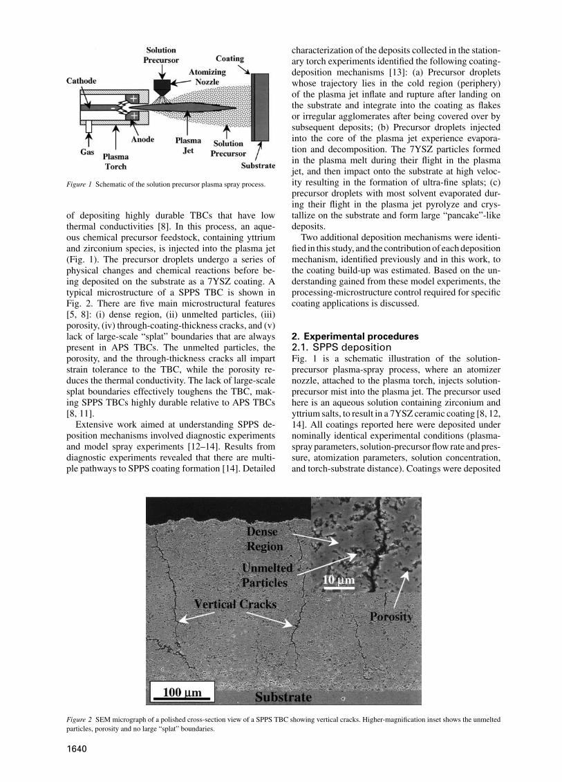
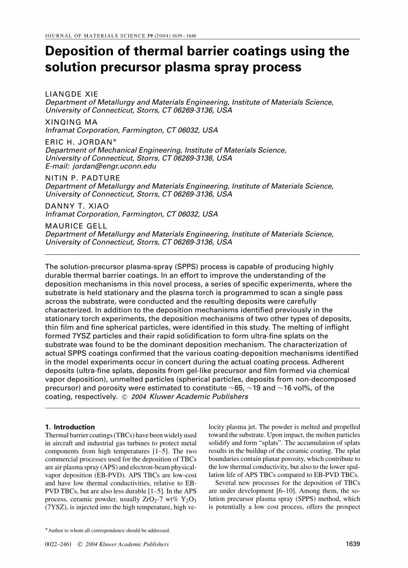
Figure 1 Schematic of the solution precursor plasma spray process.
of depositing highly durable TBCs that have lowthermal conductivities [8]. In this process, an aque-ous chemical precursor feedstock, containing yttriumand zirconium species, is injected into the plasma jet(Fig. 1). The precursor droplets undergo a series ofphysical changes and chemical reactions before be-ing deposited on the substrate as a 7YSZ coating. Atypical microstructure of a SPPS TBC is shown inFig. 2. There are five main microstructural features[5, 8]: (i) dense region, (ii) unmelted particles, (iii)porosity, (iv) through-coating-thickness cracks, and (v)lack of large-scale “splat” boundaries that are alwayspresent in APS TBCs. The unmelted particles, theporosity, and the through-thickness cracks all impartstrain tolerance to the TBC, while the porosity re-duces the thermal conductivity. The lack of large-scalesplat boundaries effectively toughens the TBC, mak-ing SPPS TBCs highly durable relative to APS TBCs[8, 11].
Extensive work aimed at understanding SPPS de-position mechanisms involved diagnostic experimentsand model spray experiments [12–14]. Results fromdiagnostic experiments revealed that there are multi-ple pathways to SPPS coating formation [14]. Detailed
Figure 2 SEM micrograph of a polished cross-section view of a SPPS TBC showing vertical cracks. Higher-magnification inset shows the unmeltedparticles, porosity and no large “splat” boundaries.
characterization of the deposits collected in the station-ary torch experiments identified the following coating-deposition mechanisms [13]: (a) Precursor dropletswhose trajectory lies in the cold region (periphery)of the plasma jet inflate and rupture after landing onthe substrate and integrate into the coating as flakesor irregular agglomerates after being covered over bysubsequent deposits; (b) Precursor droplets injectedinto the core of the plasma jet experience evapora-tion and decomposition. The 7YSZ particles formedin the plasma melt during their flight in the plasmajet, and then impact onto the substrate at high veloc-ity resulting in the formation of ultra-fine splats; (c)precursor droplets with most solvent evaporated dur-ing their flight in the plasma jet pyrolyze and crys-tallize on the substrate and form large “pancake”-likedeposits.
Two additional deposition mechanisms were identi-fied in this study, and the contribution of each depositionmechanism, identified previously and in this work, tothe coating build-up was estimated. Based on the un-derstanding gained from these model experiments, theprocessing-microstructure control required for specificcoating applications is discussed.
2. Experimental procedures2.1. SPPS depositionFig. 1 is a schematic illustration of the solution-precursor plasma-spray process, where an atomizernozzle, attached to the plasma torch, injects solution-precursor mist into the plasma jet. The precursor usedhere is an aqueous solution containing zirconium andyttrium salts, to result in a 7YSZ ceramic coating [8, 12,14]. All coatings reported here were deposited undernominally identical experimental conditions (plasma-spray parameters, solution-precursor flow rate and pres-sure, atomization parameters, solution concentration,and torch-substrate distance). Coatings were deposited
1640
on stainless steel substrates (plates 75 × 50 × 3 mmor disks 25 mm diameter, 3 mm thickness), surfacesof which were previously roughened by grit-blasting(Al2O3 grit of #320 mesh size) or polished metallo-graphically to 1 µm finish.
The direct current (DC) plasma torch used here wasthe Metco 9 MB (Sulzer Metco, Westbury, NY), whichwas attached to a 6-axis robotic arm. The plasma powerused was in the range 35 to 45 kW. Ar and H2 were usedas the primary and the secondary plasma gases, respec-tively, whereas N2 was used as the solution-precursoratomizing gas. A resistance heater was used to preheatthe substrate to a fixed high temperature, as measuredusing a thermocouple attached to the backside of thesubstrate.
In an effort to identify coating-deposition mecha-nisms other than those identified in the stationary torchexperiments and determine the dominant depositionmechanism, two types of single-line scan-spray exper-iments were performed. In the first type, the plasmatorch was programmed to scan one pass across the sub-strate at its maximum speed (∼1200 mm/s), which isreferred to as high-speed single-line experiment. In thesecond type, the plasma torch was programmed to scana single pass across the substrate at the speed normallyused for actual coating deposition (300–800 mm/s),which is referred to as normal-speed single-lineexperiment.
2.2. CharacterizationThe top surface of samples deposited in single-linescanning spray experiments were observed in a scan-ning electron microscope (SEM) (JSM6335F, Jeol,Japan) equipped with a field emission source. Depositscollected in normal-speed single-line experiments werealso observed in an optical microscope (MacrophotTM,Nikon, Japan).
Actual SPPS TBCs (300 µm) deposited using multi-pass rastering spray experiments (see details in [8, 14])were also characterized to verify the occurrence ofthe identified coating-deposition mechanisms duringthe actual coating-deposition process and to estimatetheir contribution to the coating build-up. The fracturecross-section of the freestanding coating was obtainedby notching the coating from the substrate with a dia-mond blade and then bending the coating. The exposedfracture surfaces were observed in the high-resolutionSEM.
2.3. Image analysisIn an attempt to estimate the volume of dense regionand unmelted particles in the actual coating, and hencethe contribution of each coating-deposition mechanismto the coating build-up, the polished cross-section ofthe actual coating, prepared according to standard met-allographic procedures, was ultrasonically cleaned toremove the unmelted particles, so that the dense regioncan be easily distinguished. After that, ten SEM pictureswere taken and then analyzed using an image analysessystem, microGOP 2000 (ContextVision, Linkoping,Sweden).
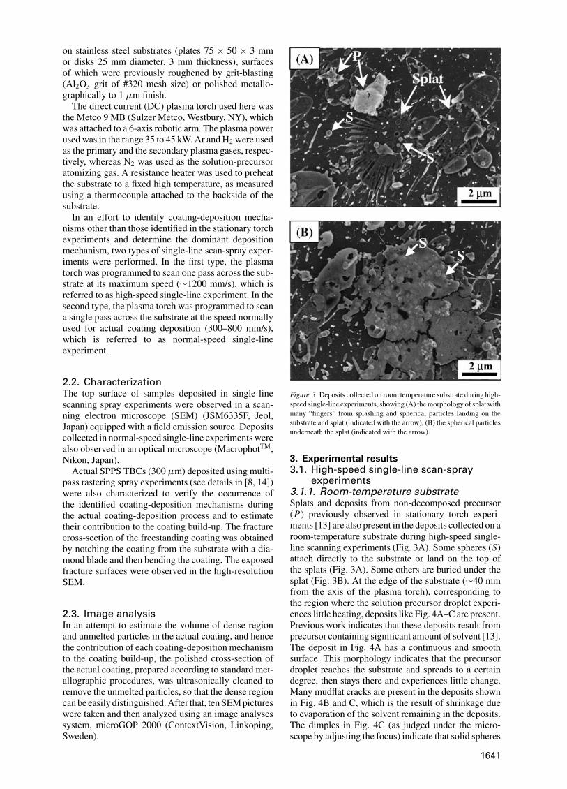
Figure 3 Deposits collected on room temperature substrate during high-speed single-line experiments, showing (A) the morphology of splat withmany “fingers” from splashing and spherical particles landing on thesubstrate and splat (indicated with the arrow), (B) the spherical particlesunderneath the splat (indicated with the arrow).
3. Experimental results3.1. High-speed single-line scan-spray
experiments3.1.1. Room-temperature substrateSplats and deposits from non-decomposed precursor(P) previously observed in stationary torch experi-ments [13] are also present in the deposits collected on aroom-temperature substrate during high-speed single-line scanning experiments (Fig. 3A). Some spheres (S)attach directly to the substrate or land on the top ofthe splats (Fig. 3A). Some others are buried under thesplat (Fig. 3B). At the edge of the substrate (∼40 mmfrom the axis of the plasma torch), corresponding tothe region where the solution precursor droplet experi-ences little heating, deposits like Fig. 4A–C are present.Previous work indicates that these deposits result fromprecursor containing significant amount of solvent [13].The deposit in Fig. 4A has a continuous and smoothsurface. This morphology indicates that the precursordroplet reaches the substrate and spreads to a certaindegree, then stays there and experiences little change.Many mudflat cracks are present in the deposits shownin Fig. 4B and C, which is the result of shrinkage dueto evaporation of the solvent remaining in the deposits.The dimples in Fig. 4C (as judged under the micro-scope by adjusting the focus) indicate that solid spheres
1641
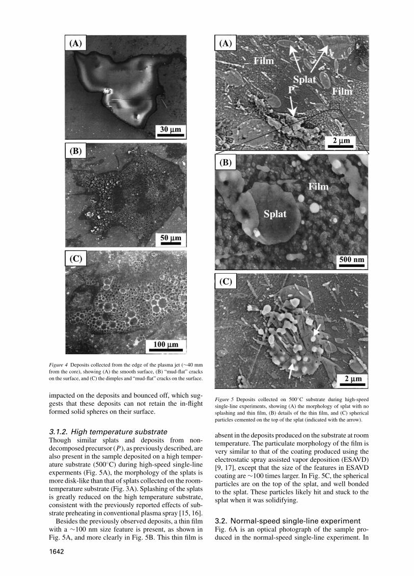
Figure 4 Deposits collected from the edge of the plasma jet (∼40 mmfrom the core), showing (A) the smooth surface, (B) “mud-flat” crackson the surface, and (C) the dimples and “mud-flat” cracks on the surface.
impacted on the deposits and bounced off, which sug-gests that these deposits can not retain the in-flightformed solid spheres on their surface.
3.1.2. High temperature substrateThough similar splats and deposits from non-decomposed precursor (P), as previously described, arealso present in the sample deposited on a high temper-ature substrate (500◦C) during high-speed single-lineexperments (Fig. 5A), the morphology of the splats ismore disk-like than that of splats collected on the room-temperature substrate (Fig. 3A). Splashing of the splatsis greatly reduced on the high temperature substrate,consistent with the previously reported effects of sub-strate preheating in conventional plasma spray [15, 16].
Besides the previously observed deposits, a thin filmwith a ∼100 nm size feature is present, as shown inFig. 5A, and more clearly in Fig. 5B. This thin film is
Figure 5 Deposits collected on 500◦C substrate during high-speedsingle-line experiments, showing (A) the morphology of splat with nosplashing and thin film, (B) details of the thin film, and (C) sphericalparticles cemented on the top of the splat (indicated with the arrow).
absent in the deposits produced on the substrate at roomtemperature. The particulate morphology of the film isvery similar to that of the coating produced using theelectrostatic spray assisted vapor deposition (ESAVD)[9, 17], except that the size of the features in ESAVDcoating are ∼100 times larger. In Fig. 5C, the sphericalparticles are on the top of the splat, and well bondedto the splat. These particles likely hit and stuck to thesplat when it was solidifying.
3.2. Normal-speed single-line experimentFig. 6A is an optical photograph of the sample pro-duced in the normal-speed single-line experiment. In
1642
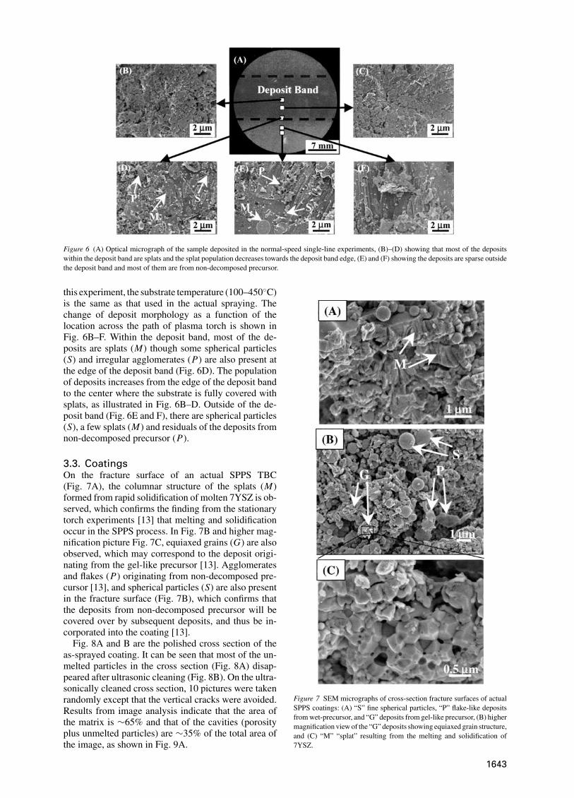
Figure 6 (A) Optical micrograph of the sample deposited in the normal-speed single-line experiments, (B)–(D) showing that most of the depositswithin the deposit band are splats and the splat population decreases towards the deposit band edge, (E) and (F) showing the deposits are sparse outsidethe deposit band and most of them are from non-decomposed precursor.
this experiment, the substrate temperature (100–450◦C)is the same as that used in the actual spraying. Thechange of deposit morphology as a function of thelocation across the path of plasma torch is shown inFig. 6B–F. Within the deposit band, most of the de-posits are splats (M) though some spherical particles(S) and irregular agglomerates (P) are also present atthe edge of the deposit band (Fig. 6D). The populationof deposits increases from the edge of the deposit bandto the center where the substrate is fully covered withsplats, as illustrated in Fig. 6B–D. Outside of the de-posit band (Fig. 6E and F), there are spherical particles(S), a few splats (M) and residuals of the deposits fromnon-decomposed precursor (P).
3.3. CoatingsOn the fracture surface of an actual SPPS TBC(Fig. 7A), the columnar structure of the splats (M)formed from rapid solidification of molten 7YSZ is ob-served, which confirms the finding from the stationarytorch experiments [13] that melting and solidificationoccur in the SPPS process. In Fig. 7B and higher mag-nification picture Fig. 7C, equiaxed grains (G) are alsoobserved, which may correspond to the deposit origi-nating from the gel-like precursor [13]. Agglomeratesand flakes (P) originating from non-decomposed pre-cursor [13], and spherical particles (S) are also presentin the fracture surface (Fig. 7B), which confirms thatthe deposits from non-decomposed precursor will becovered over by subsequent deposits, and thus be in-corporated into the coating [13].
Fig. 8A and B are the polished cross section of theas-sprayed coating. It can be seen that most of the un-melted particles in the cross section (Fig. 8A) disap-peared after ultrasonic cleaning (Fig. 8B). On the ultra-sonically cleaned cross section, 10 pictures were takenrandomly except that the vertical cracks were avoided.Results from image analysis indicate that the area ofthe matrix is ∼65% and that of the cavities (porosityplus unmelted particles) are ∼35% of the total area ofthe image, as shown in Fig. 9A.
Figure 7 SEM micrographs of cross-section fracture surfaces of actualSPPS coatings: (A) “S” fine spherical particles, “P” flake-like depositsfrom wet-precursor, and “G” deposits from gel-like precursor, (B) highermagnification view of the “G” deposits showing equiaxed grain structure,and (C) “M” “splat” resulting from the melting and solidification of7YSZ.
1643
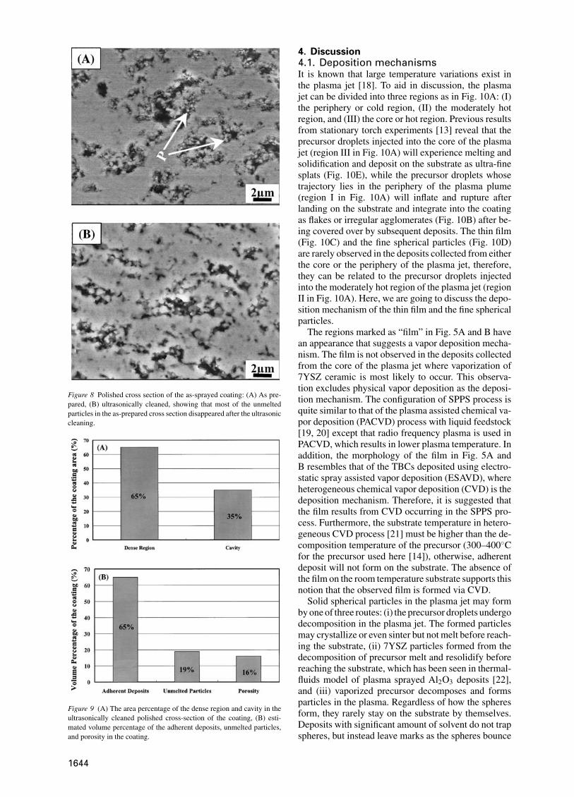
Figure 8 Polished cross section of the as-sprayed coating: (A) As pre-pared, (B) ultrasonically cleaned, showing that most of the unmeltedparticles in the as-prepared cross section disappeared after the ultrasoniccleaning.
Figure 9 (A) The area percentage of the dense region and cavity in theultrasonically cleaned polished cross-section of the coating, (B) esti-mated volume percentage of the adherent deposits, unmelted particles,and porosity in the coating.
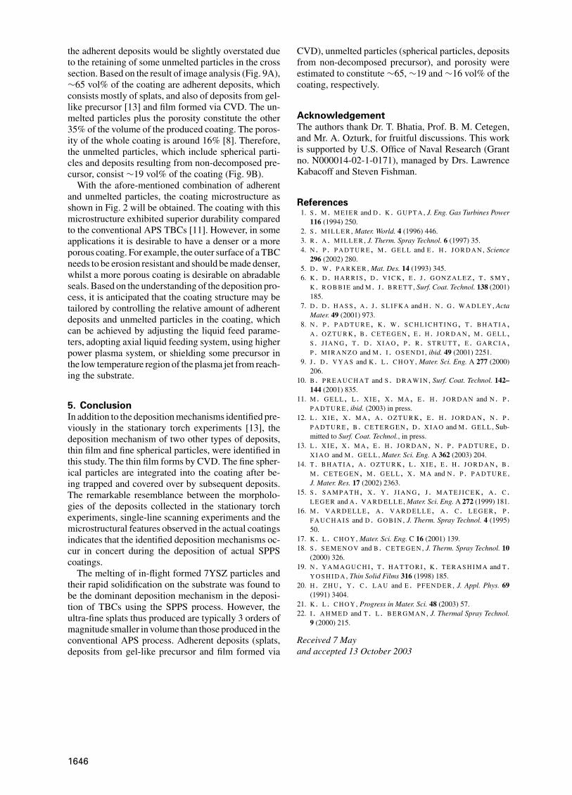
4. Discussion4.1. Deposition mechanismsIt is known that large temperature variations exist inthe plasma jet [18]. To aid in discussion, the plasmajet can be divided into three regions as in Fig. 10A: (I)the periphery or cold region, (II) the moderately hotregion, and (III) the core or hot region. Previous resultsfrom stationary torch experiments [13] reveal that theprecursor droplets injected into the core of the plasmajet (region III in Fig. 10A) will experience melting andsolidification and deposit on the substrate as ultra-finesplats (Fig. 10E), while the precursor droplets whosetrajectory lies in the periphery of the plasma plume(region I in Fig. 10A) will inflate and rupture afterlanding on the substrate and integrate into the coatingas flakes or irregular agglomerates (Fig. 10B) after be-ing covered over by subsequent deposits. The thin film(Fig. 10C) and the fine spherical particles (Fig. 10D)are rarely observed in the deposits collected from eitherthe core or the periphery of the plasma jet, therefore,they can be related to the precursor droplets injectedinto the moderately hot region of the plasma jet (regionII in Fig. 10A). Here, we are going to discuss the depo-sition mechanism of the thin film and the fine sphericalparticles.
The regions marked as “film” in Fig. 5A and B havean appearance that suggests a vapor deposition mecha-nism. The film is not observed in the deposits collectedfrom the core of the plasma jet where vaporization of7YSZ ceramic is most likely to occur. This observa-tion excludes physical vapor deposition as the deposi-tion mechanism. The configuration of SPPS process isquite similar to that of the plasma assisted chemical va-por deposition (PACVD) process with liquid feedstock[19, 20] except that radio frequency plasma is used inPACVD, which results in lower plasma temperature. Inaddition, the morphology of the film in Fig. 5A andB resembles that of the TBCs deposited using electro-static spray assisted vapor deposition (ESAVD), whereheterogeneous chemical vapor deposition (CVD) is thedeposition mechanism. Therefore, it is suggested thatthe film results from CVD occurring in the SPPS pro-cess. Furthermore, the substrate temperature in hetero-geneous CVD process [21] must be higher than the de-composition temperature of the precursor (300–400◦Cfor the precursor used here [14]), otherwise, adherentdeposit will not form on the substrate. The absence ofthe film on the room temperature substrate supports thisnotion that the observed film is formed via CVD.
Solid spherical particles in the plasma jet may formby one of three routes: (i) the precursor droplets undergodecomposition in the plasma jet. The formed particlesmay crystallize or even sinter but not melt before reach-ing the substrate, (ii) 7YSZ particles formed from thedecomposition of precursor melt and resolidify beforereaching the substrate, which has been seen in thermal-fluids model of plasma sprayed Al2O3 deposits [22],and (iii) vaporized precursor decomposes and formsparticles in the plasma. Regardless of how the spheresform, they rarely stay on the substrate by themselves.Deposits with significant amount of solvent do not trapspheres, but instead leave marks as the spheres bounce
1644
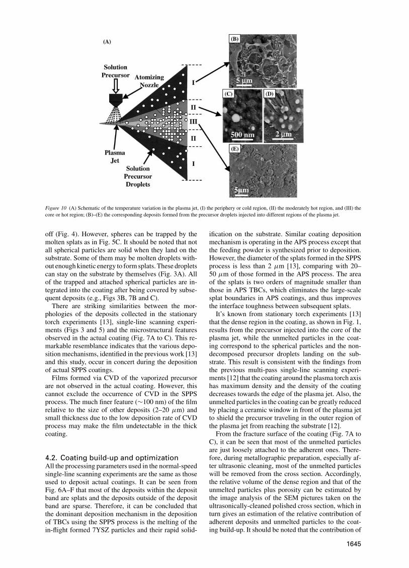
Figure 10 (A) Schematic of the temperature variation in the plasma jet, (I) the periphery or cold region, (II) the moderately hot region, and (III) thecore or hot region; (B)–(E) the corresponding deposits formed from the precursor droplets injected into different regions of the plasma jet.
off (Fig. 4). However, spheres can be trapped by themolten splats as in Fig. 5C. It should be noted that notall spherical particles are solid when they land on thesubstrate. Some of them may be molten droplets with-out enough kinetic energy to form splats. These dropletscan stay on the substrate by themselves (Fig. 3A). Allof the trapped and attached spherical particles are in-tegrated into the coating after being covered by subse-quent deposits (e.g., Figs 3B, 7B and C).
There are striking similarities between the mor-phologies of the deposits collected in the stationarytorch experiments [13], single-line scanning experi-ments (Figs 3 and 5) and the microstructural featuresobserved in the actual coating (Fig. 7A to C). This re-markable resemblance indicates that the various depo-sition mechanisms, identified in the previous work [13]and this study, occur in concert during the depositionof actual SPPS coatings.
Films formed via CVD of the vaporized precursorare not observed in the actual coating. However, thiscannot exclude the occurrence of CVD in the SPPSprocess. The much finer feature (∼100 nm) of the filmrelative to the size of other deposits (2–20 µm) andsmall thickness due to the low deposition rate of CVDprocess may make the film undetectable in the thickcoating.
4.2. Coating build-up and optimizationAll the processing parameters used in the normal-speedsingle-line scanning experiments are the same as thoseused to deposit actual coatings. It can be seen fromFig. 6A–F that most of the deposits within the depositband are splats and the deposits outside of the depositband are sparse. Therefore, it can be concluded thatthe dominant deposition mechanism in the depositionof TBCs using the SPPS process is the melting of thein-flight formed 7YSZ particles and their rapid solid-
ification on the substrate. Similar coating depositionmechanism is operating in the APS process except thatthe feeding powder is synthesized prior to deposition.However, the diameter of the splats formed in the SPPSprocess is less than 2 µm [13], comparing with 20–50 µm of those formed in the APS process. The areaof the splats is two orders of magnitude smaller thanthose in APS TBCs, which eliminates the large-scalesplat boundaries in APS coatings, and thus improvesthe interface toughness between subsequent splats.
It’s known from stationary torch experiments [13]that the dense region in the coating, as shown in Fig. 1,results from the precursor injected into the core of theplasma jet, while the unmelted particles in the coat-ing correspond to the spherical particles and the non-decomposed precursor droplets landing on the sub-strate. This result is consistent with the findings fromthe previous multi-pass single-line scanning experi-ments [12] that the coating around the plasma torch axishas maximum density and the density of the coatingdecreases towards the edge of the plasma jet. Also, theunmelted particles in the coating can be greatly reducedby placing a ceramic window in front of the plasma jetto shield the precursor traveling in the outer region ofthe plasma jet from reaching the substrate [12].
From the fracture surface of the coating (Fig. 7A toC), it can be seen that most of the unmelted particlesare just loosely attached to the adherent ones. There-fore, during metallographic preparation, especially af-ter ultrasonic cleaning, most of the unmelted particleswill be removed from the cross section. Accordingly,the relative volume of the dense region and that of theunmelted particles plus porosity can be estimated bythe image analysis of the SEM pictures taken on theultrasonically-cleaned polished cross section, which inturn gives an estimation of the relative contribution ofadherent deposits and unmelted particles to the coat-ing build-up. It should be noted that the contribution of
1645
the adherent deposits would be slightly overstated dueto the retaining of some unmelted particles in the crosssection. Based on the result of image analysis (Fig. 9A),∼65 vol% of the coating are adherent deposits, whichconsists mostly of splats, and also of deposits from gel-like precursor [13] and film formed via CVD. The un-melted particles plus the porosity constitute the other35% of the volume of the produced coating. The poros-ity of the whole coating is around 16% [8]. Therefore,the unmelted particles, which include spherical parti-cles and deposits resulting from non-decomposed pre-cursor, consist ∼19 vol% of the coating (Fig. 9B).
With the afore-mentioned combination of adherentand unmelted particles, the coating microstructure asshown in Fig. 2 will be obtained. The coating with thismicrostructure exhibited superior durability comparedto the conventional APS TBCs [11]. However, in someapplications it is desirable to have a denser or a moreporous coating. For example, the outer surface of a TBCneeds to be erosion resistant and should be made denser,whilst a more porous coating is desirable on abradableseals. Based on the understanding of the deposition pro-cess, it is anticipated that the coating structure may betailored by controlling the relative amount of adherentdeposits and unmelted particles in the coating, whichcan be achieved by adjusting the liquid feed parame-ters, adopting axial liquid feeding system, using higherpower plasma system, or shielding some precursor inthe low temperature region of the plasma jet from reach-ing the substrate.
5. ConclusionIn addition to the deposition mechanisms identified pre-viously in the stationary torch experiments [13], thedeposition mechanism of two other types of deposits,thin film and fine spherical particles, were identified inthis study. The thin film forms by CVD. The fine spher-ical particles are integrated into the coating after be-ing trapped and covered over by subsequent deposits.The remarkable resemblance between the morpholo-gies of the deposits collected in the stationary torchexperiments, single-line scanning experiments and themicrostructural features observed in the actual coatingsindicates that the identified deposition mechanisms oc-cur in concert during the deposition of actual SPPScoatings.
The melting of in-flight formed 7YSZ particles andtheir rapid solidification on the substrate was found tobe the dominant deposition mechanism in the deposi-tion of TBCs using the SPPS process. However, theultra-fine splats thus produced are typically 3 orders ofmagnitude smaller in volume than those produced in theconventional APS process. Adherent deposits (splats,deposits from gel-like precursor and film formed via
CVD), unmelted particles (spherical particles, depositsfrom non-decomposed precursor), and porosity wereestimated to constitute ∼65, ∼19 and ∼16 vol% of thecoating, respectively.
AcknowledgementThe authors thank Dr. T. Bhatia, Prof. B. M. Cetegen,and Mr. A. Ozturk, for fruitful discussions. This workis supported by U.S. Office of Naval Research (Grantno. N000014-02-1-0171), managed by Drs. LawrenceKabacoff and Steven Fishman.
References1. S . M. M E I E R and D. K. G U P T A , J. Eng. Gas Turbines Power
116 (1994) 250.2. S . M I L L E R , Mater. World. 4 (1996) 446.3. R . A . M I L L E R , J. Therm. Spray Technol. 6 (1997) 35.4. N . P . P A D T U R E, M. G E L L and E . H. J O R D A N , Science
296 (2002) 280.5. D . W. P A R K E R , Mat. Des. 14 (1993) 345.6. K . D . H A R R I S , D . V I C K, E . J . G O N Z A L E Z, T . S M Y,
K. R O B B I E and M. J . B R E T T , Surf. Coat. Technol. 138 (2001)185.
7. D . D . H A S S , A. J . S L I F K A and H. N. G. W A D L E Y , ActaMater. 49 (2001) 973.
8. N . P . P A D T U R E, K. W. S C H L I C H T I N G, T . B H A T I A,A. O Z T U R K, B. C E T E G E N, E . H . J O R D A N, M. G E L L,S . J I A N G, T . D . X I A O, P . R . S T R U T T, E . G A R C I A,P . M I R A N Z O and M. I . O S E N D I , ibid. 49 (2001) 2251.
9. J . D . V Y A S and K. L . C H O Y , Mater. Sci. Eng. A 277 (2000)206.
10. B . P R E A U C H A T and S . D R A W I N , Surf. Coat. Technol. 142–144 (2001) 835.
11. M. G E L L, L . X I E , X . M A, E . H . J O R D A N and N. P .P A D T U R E , ibid. (2003) in press.
12. L . X I E , X . M A, A. O Z T U R K, E . H . J O R D A N, N. P .P A D T U R E, B . C E T E R G E N, D. X I A O and M. G E L L , Sub-mitted to Surf. Coat. Technol., in press.
13. L . X I E , X . M A, E . H . J O R D A N, N. P . P A D T U R E, D.X I A O and M. G E L L , Mater. Sci. Eng. A 362 (2003) 204.
14. T . B H A T I A, A. O Z T U R K, L . X I E , E . H . J O R D A N, B.M. C E T E G E N, M. G E L L, X. M A and N. P . P A D T U R E ,J. Mater. Res. 17 (2002) 2363.
15. S . S A M P A T H, X. Y. J I A N G, J . M A T E J I C E K, A. C .L E G E R and A. V A R D E L L E , Mater. Sci. Eng. A 272 (1999) 181.
16. M. V A R D E L L E, A. V A R D E L L E, A. C . L E G E R, P .F A U C H A I S and D. G O B I N , J. Therm. Spray Technol. 4 (1995)50.
17. K . L . C H O Y , Mater. Sci. Eng. C 16 (2001) 139.18. S . S E M E N O V and B. C E T E G E N , J. Therm. Spray Technol. 10
(2000) 326.19. N . Y A M A G U C H I , T . H A T T O R I , K . T E R A S H I M A and T.
Y O S H I D A , Thin Solid Films 316 (1998) 185.20. H . Z H U, Y. C . L A U and E . P F E N D E R , J. Appl. Phys. 69
(1991) 3404.21. K . L . C H O Y , Progress in Mater. Sci. 48 (2003) 57.22. I . A H M E D and T. L . B E R G M A N , J. Thermal Spray Technol.
9 (2000) 215.
Received 7 Mayand accepted 13 October 2003
1646