Embed Size (px)
Citation preview
Depositing - The Future of Hard Candy
By
Martin J. Bond - Chief Engineer, Confectionery Products
Tony Prange - Senior Application Engineer
Baker Perkins Ltd
Introduction
Hard candy depositing is a process that has developed and grown rapidly over the last 20 years.
Deposited hard candies and lollipops are now produced in every major confectionery market
around the world by manufacturers ranging from regional specialists to major multi-nationals.
First introduced over 50 years ago, depositing remained a niche technology until confectioners
recognised its potential to meet increasing market demand for premium, high-quality,
innovative products. Since then it has, time and again, been the technology that has enabled
them to push back the boundaries of innovation by developing hard candies and lollipops that
would be inconceivable with traditional processes. Today, it continues to progress, offering
manufacturers an ever widening range of opportunities to blend visual appeal with exciting taste
and texture combinations.
This paper will review the basic principles of depositing and discuss the fundamental aspects of
design that should be considered when engineering a complete depositing solution. A study will
also be made of each of the main candy types frequently produced today; solid, striped,
centre-filled, short and long layered, and lollipops with the important process and engineering
criteria highlighted. The paper will also examine many of the changes and improvements seen
over the last 50 years, and speculate about the developments that will shape the future of
depositing.
PAGE | 2Depositing - The Future of Hard Candy
Deposited Candy
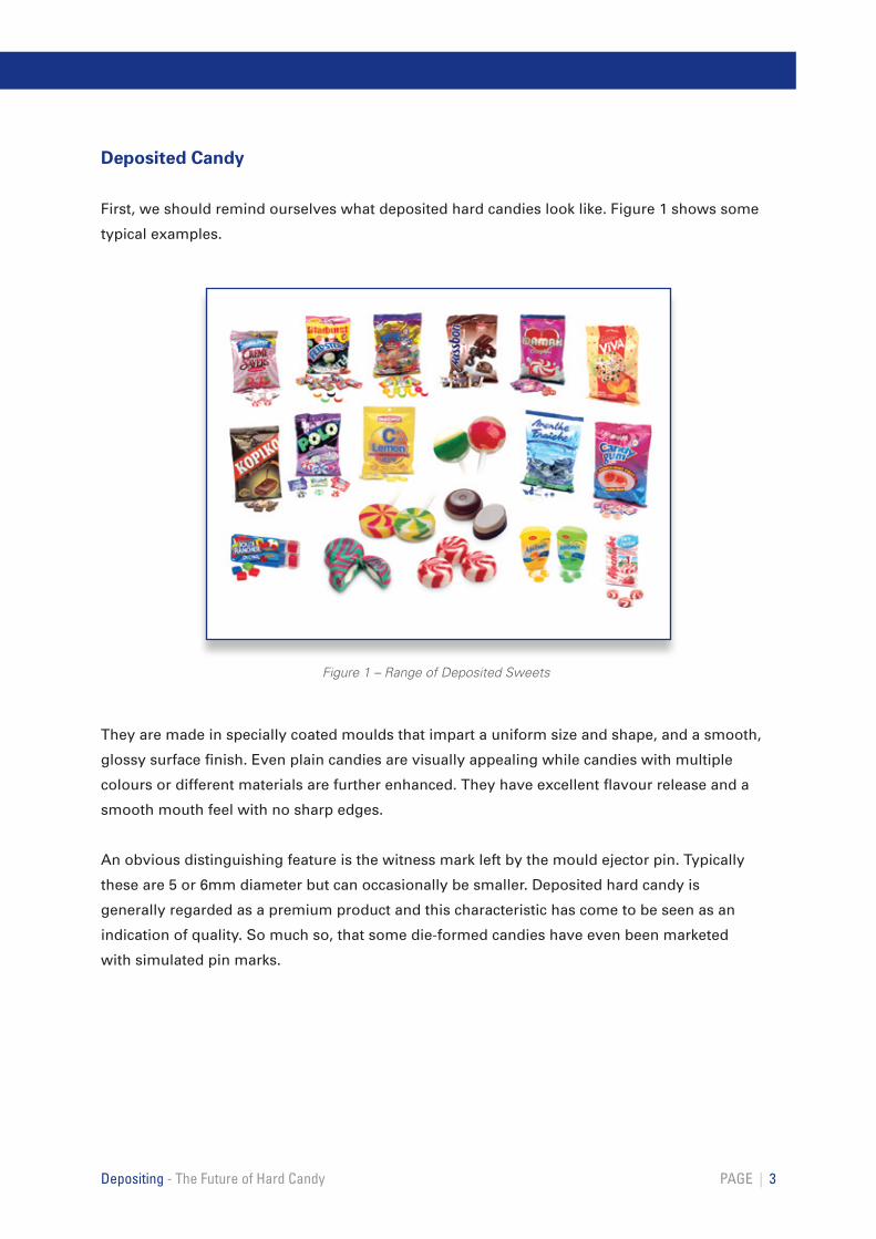
First, we should remind ourselves what deposited hard candies look like. Figure 1 shows some
typical examples.
They are made in specially coated moulds that impart a uniform size and shape, and a smooth,
glossy surface finish. Even plain candies are visually appealing while candies with multiple
colours or different materials are further enhanced. They have excellent flavour release and a
smooth mouth feel with no sharp edges.
An obvious distinguishing feature is the witness mark left by the mould ejector pin. Typically
these are 5 or 6mm diameter but can occasionally be smaller. Deposited hard candy is
generally regarded as a premium product and this characteristic has come to be seen as an
indication of quality. So much so, that some die-formed candies have even been marketed
with simulated pin marks.
PAGE | 3Depositing - The Future of Hard Candy
Figure 1 – Range of Deposited Sweets
Basic Depositor Principle
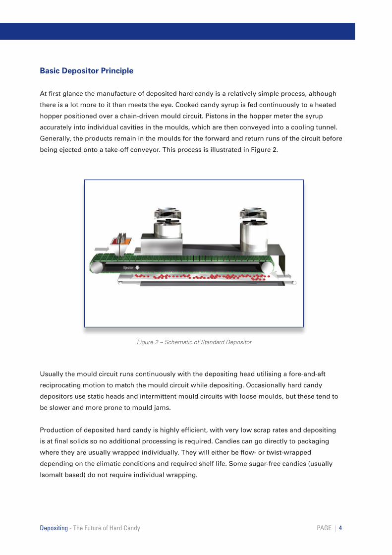
At first glance the manufacture of deposited hard candy is a relatively simple process, although
there is a lot more to it than meets the eye. Cooked candy syrup is fed continuously to a heated
hopper positioned over a chain-driven mould circuit. Pistons in the hopper meter the syrup
accurately into individual cavities in the moulds, which are then conveyed into a cooling tunnel.
Generally, the products remain in the moulds for the forward and return runs of the circuit before
being ejected onto a take-off conveyor. This process is illustrated in Figure 2.
Usually the mould circuit runs continuously with the depositing head utilising a fore-and-aft
reciprocating motion to match the mould circuit while depositing. Occasionally hard candy
depositors use static heads and intermittent mould circuits with loose moulds, but these tend to
be slower and more prone to mould jams.
Production of deposited hard candy is highly efficient, with very low scrap rates and depositing
is at final solids so no additional processing is required. Candies can go directly to packaging
where they are usually wrapped individually. They will either be flow- or twist-wrapped
depending on the climatic conditions and required shelf life. Some sugar-free candies (usually
Isomalt based) do not require individual wrapping.
PAGE | 4Depositing - The Future of Hard Candy
Figure 2 – Schematic of Standard Depositor

The fundamental principles of depositing have remained the same since it was introduced
over 50 years ago. However, advances in technology, particularly control systems, would render
modern machines virtually unrecognisable to the pioneers of the process. The first continuous
depositors were relatively low output, usually just one mould wide, with no more than 8
cavities across. These depositors were mechanical with all the machine movements driven by
cams linked to the mould circuit. They would have one hopper typically producing about 200 to
500 single colour candies per minute. Figure 3a illustrates one of these early depositors.
PAGE | 5Depositing - The Future of Hard Candy
Figure 3a – Early Depositor – circa 1960
Today’s machines feature sophisticated
servo-drives and PLC control systems instead
of mechanical cams and linkages. These
enable the same depositor to be used to make a
very wide range of products and to be changed
over at the touch of a button. Current depositors
are usually wider, up to 1.5 metres, often have
double hoppers, operate at higher speeds and
deposit 2, 3 or 4 rows of candies on each cycle.
Multi-headed versions are available to further
increase versatility and output. It is quite
common for modern plants to produce over
10,000 candies per minute. One of these recent
high output flexible depositors is illustrated in
Figure 3b.
Figure 3b - Modern Depositor
Depositor Process Design
While the principles of depositing are straightforward the successful production of deposited
hard candies and lollipops requires a good understanding of the whole process, from raw
materials through to wrapping. With this knowledge it is possible to make a very high-quality
sweet very efficiently. However, if starting with poor-quality raw materials even the best
depositor will be unable to make a high-quality product. Similarly, a poor depositor running
with high-quality ingredients will not make a good product either.
Recipes
There are many deposited hard candies available today, but the majority fall into one of three
generic categories: clear candy, cream candy and milk boil (high-milk) candy (Figure 4). All of
these recipes are continuously cooked, typically to a final moisture content of 2.5% to 3%. To
achieve this it is necessary to cook the syrup atmospherically to approximately 150ºC or lower
if vacuum is applied.
The clear candy recipe is typically used to make coloured fruit-flavoured candies, often with
layers or multiple stripes, or clear mint candies. It is also used for many centre-filled candies with
either solid or liquid centres. If the correct raw materials and process are used very clear sweets
can be produced.
The cream candy recipe is one of the most popular today. This is usually the base recipe for
striped fruit and cream candies, of which many types are produced globally. These recipes
typically contain about 5% cream, which should have a high fat and low protein content to avoid
the syrup caramelising. In the United Kingdom Double Cream (48% fat, 1.7% protein) is often
used whereas in the United States Heavy Cream (40% fat, 1.7% protein) is preferred.
PAGE | 6Depositing - The Future of Hard Candy
The milk boil recipe is usually used to produce a high milk content, solid hard candy with a rich,
caramelised flavour. Recently many manufacturers have started to centre-fill these products with
real chocolate or soft caramel. The recipes deliberately have higher protein contents than the
previous cream-candy recipe, to ensure caramelisation takes place. It is sometimes also
necessary to increase the residence time between the cooker and depositor to allow the colour
to develop. These recipes will often contain full-cream sweetened condensed milk or whey
powders, which have higher protein levels.
When it is difficult to source a suitable fresh cream it is usually possible to make an acceptable
alternative using either milk powder with additional fat or, preferably, a cream powder with a
high fat content. These powders have to be carefully rehydrated and mixed using high-shear
mixers or homogenisers. To maximise cooker output the amount of added water should
be minimised.
Advances in ingredient and cooking technologies have enabled sugar-free candies to be
deposited with few problems. The most common sugar-free material used is Isomalt. To achieve
a stable product the Isomalt has to be cooked to lower moisture contents than sugar candy
(typically 1% to 1.8%) requiring higher cook temperatures with increased vacuum.
Maltitol syrups are also used but do not necessarily need cooking to such high temperatures.
However the final candies are very hygroscopic and need to be individually wrapped.
Most sugar-free recipes are less sweet than sugar recipes. To overcome this intense sweeteners
are added (aspartame, acesulfame-K, sucralose, Stevia etc.) It is also possible to make sugar-free
products using cream and other additions.
PAGE | 7Depositing - The Future of Hard Candy
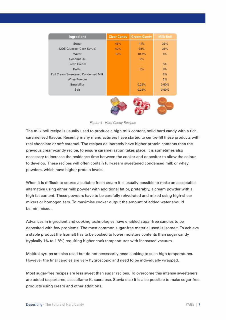
Ingredient
Sugar
42DE Glucose (Corn Syrup)
Water
Coconut Oil
Fresh Cream
Butter
Full Cream Sweetened Condensed Milk
Whey Powder
Emulsifier
Salt
Clear Candy
46%
42%
12%
Cream Candy
41%
38%
10.5%
5%
5%
0.25%
0.25%
Milk Boil
39%
35%
8%
5%
8%
2%
2%
0.50%
0.50%
Figure 4 - Hard Candy Recipes
Graining and Inversion
All the recipes tabled contain predominantly sugar and glucose (corn syrup) and it is important
that the ratio between them is correct. If the sugar level is too high there is the possibility that
the candy will re-crystallise or grain. This may occur in the final product only after wrapping,
affecting shelf life and leading to consumer complaints. It is more likely that it will first be seen
in the depositor hopper as the shearing action of the pistons can initiate the re-crystallisation
process. It will start as a slight cloudiness in the syrup, possibly around the pistons, and then
spread, throughout the hopper, eventually necessitating a production shutdown and
thorough wash-out.
Conversely, if the glucose level is too high there may be excessive inversion (presence of invert
sugars). This can also lead to shelf life problems and consumer complaints about candies
being discoloured and sticky. On the production line this inversion will first be seen as
discoloured candy and may lead to difficulties with ejection and wrapping.
Many of these problems can be avoided or minimised by choosing the right recipe and
selecting the correct raw materials. Often depositors are installed in factories that already run
other processes, for example die-forming, and although it is tempting to assume that the same
raw materials and recipes can be used, depositing is a unique process and manufacturers
should appreciate that different recipes will be required.
High-maltose glucose warrants a special mention. It is now regularly used in deposited candy
recipes instead of standard 42DE glucose. Glucose syrups with high maltose levels are more
fluid and produce lower viscosity candy syrups, which reduces tailing. The final candies are
also clearer, less prone to discolouration and less hygroscopic. However they can be slightly
more brittle.
PAGE | 8 Depositing - The Future of Hard Candy
Cooking
Having developed a recipe and selected the raw materials the next stage is to choose the best
cooking process to feed the depositor. A good understanding of sugar boiling curves and the
effect of pressure and vacuum will help with this selection.
The cooking is usually considered in two discrete stages: dissolving the granulated sugar and
evaporating the resultant syrup to achieve the required final solids. The dissolving stage should
have a retention time long enough to ensure all the sugar is fully dissolved. The most common
continuous dissolving systems today are coil cookers or plate heat exchangers (PHE).
Sometimes these will be configured with back pressure to allow less water to be used with
a resultant energy saving.
For depositing, the candy syrup must be evaporated to final solids as quickly as possible. This
avoids heat degradation and process inversion, which can cause shelf life problems such as cold
flow and stickiness. Continuous cookers with short residence times and the ability to use vacuum
should be selected. The application of vacuum allows the required final moisture to be achieved
at lower cooking temperatures.
PAGE | 9Depositing - The Future of Hard Candy
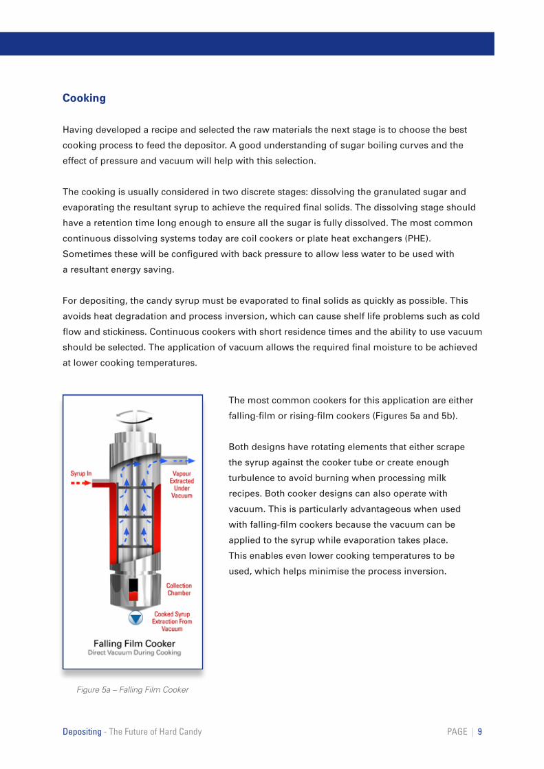
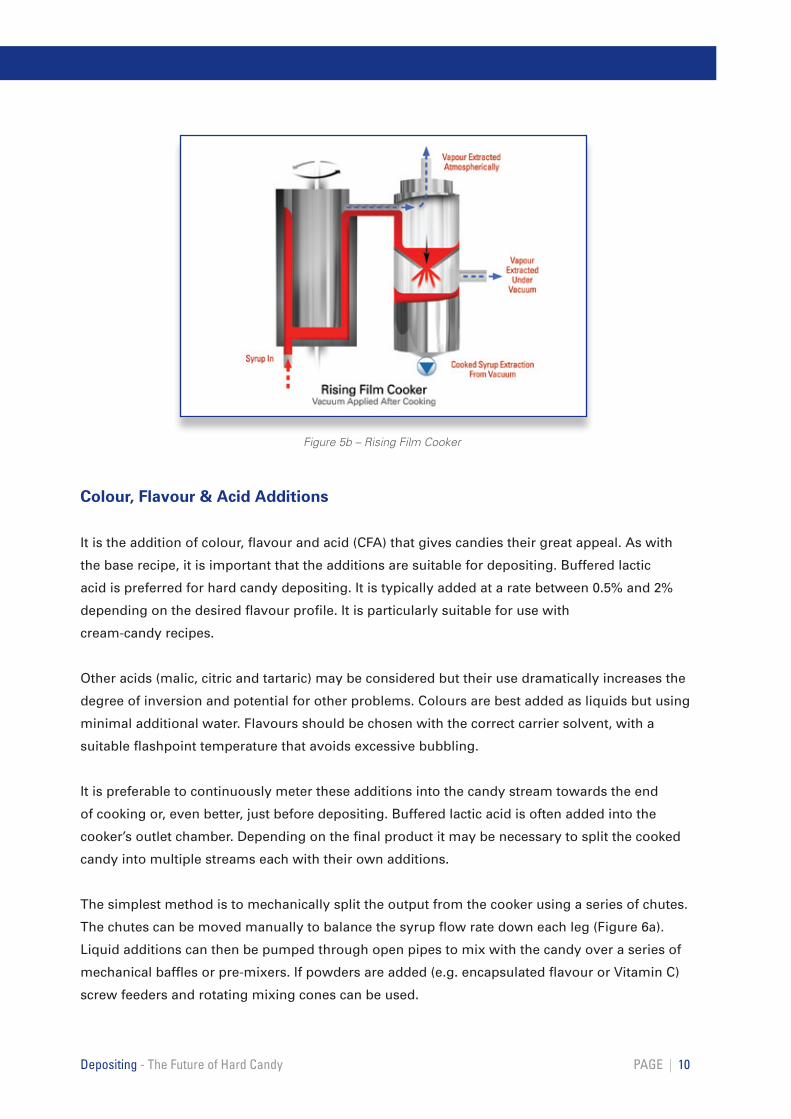
Figure 5a – Falling Film Cooker
The most common cookers for this application are either
falling-film or rising-film cookers (Figures 5a and 5b).
Both designs have rotating elements that either scrape
the syrup against the cooker tube or create enough
turbulence to avoid burning when processing milk
recipes. Both cooker designs can also operate with
vacuum. This is particularly advantageous when used
with falling-film cookers because the vacuum can be
applied to the syrup while evaporation takes place.
This enables even lower cooking temperatures to be
used, which helps minimise the process inversion.
Colour, Flavour & Acid Additions
It is the addition of colour, flavour and acid (CFA) that gives candies their great appeal. As with
the base recipe, it is important that the additions are suitable for depositing. Buffered lactic
acid is preferred for hard candy depositing. It is typically added at a rate between 0.5% and 2%
depending on the desired flavour profile. It is particularly suitable for use with
cream-candy recipes.
Other acids (malic, citric and tartaric) may be considered but their use dramatically increases the
degree of inversion and potential for other problems. Colours are best added as liquids but using
minimal additional water. Flavours should be chosen with the correct carrier solvent, with a
suitable flashpoint temperature that avoids excessive bubbling.
It is preferable to continuously meter these additions into the candy stream towards the end
of cooking or, even better, just before depositing. Buffered lactic acid is often added into the
cooker’s outlet chamber. Depending on the final product it may be necessary to split the cooked
candy into multiple streams each with their own additions.
The simplest method is to mechanically split the output from the cooker using a series of chutes.
The chutes can be moved manually to balance the syrup flow rate down each leg (Figure 6a).
Liquid additions can then be pumped through open pipes to mix with the candy over a series of
mechanical baffles or pre-mixers. If powders are added (e.g. encapsulated flavour or Vitamin C)
screw feeders and rotating mixing cones can be used.
PAGE | 10 Depositing - The Future of Hard Candy
Figure 5b – Rising Film Cooker
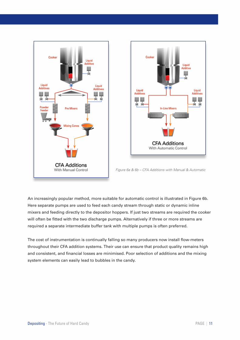
An increasingly popular method, more suitable for automatic control is illustrated in Figure 6b.
Here separate pumps are used to feed each candy stream through static or dynamic inline
mixers and feeding directly to the depositor hoppers. If just two streams are required the cooker
will often be fitted with the two discharge pumps. Alternatively if three or more streams are
required a separate intermediate buffer tank with multiple pumps is often preferred.
The cost of instrumentation is continually falling so many producers now install flow-meters
throughout their CFA addition systems. Their use can ensure that product quality remains high
and consistent, and financial losses are minimised. Poor selection of additions and the mixing
system elements can easily lead to bubbles in the candy.
PAGE | 11Depositing - The Future of Hard Candy
Figure 6a & 6b – CFA Additions with Manual & Automatic
Depositor Features
Depositor Head
The final cooked candy with its additions is normally fed directly to the depositing head. To
prevent re-boiling and bubble formation the hoppers should be heated to a temperature just
below the candy’s boiling point. Electric or oil heated hopper jackets are usually used for this.
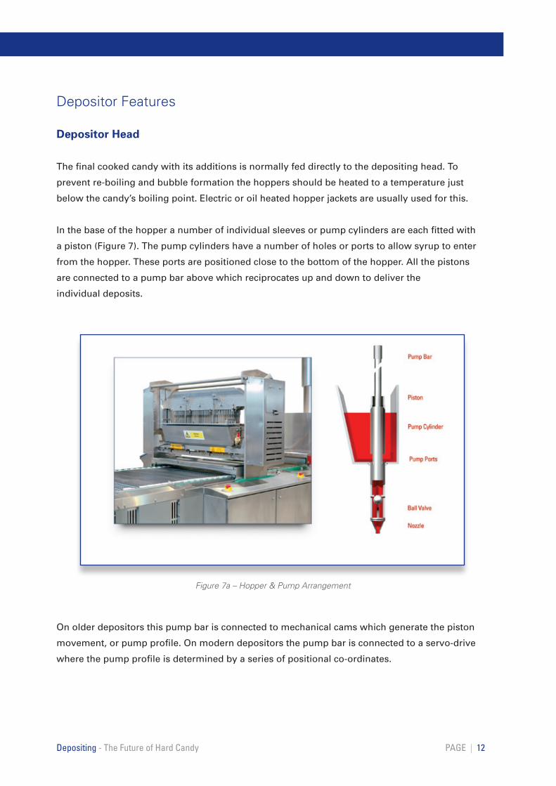
In the base of the hopper a number of individual sleeves or pump cylinders are each fitted with
a piston (Figure 7). The pump cylinders have a number of holes or ports to allow syrup to enter
from the hopper. These ports are positioned close to the bottom of the hopper. All the pistons
are connected to a pump bar above which reciprocates up and down to deliver the
individual deposits.
On older depositors this pump bar is connected to mechanical cams which generate the piston
movement, or pump profile. On modern depositors the pump bar is connected to a servo-drive
where the pump profile is determined by a series of positional co-ordinates.
PAGE | 12Depositing - The Future of Hard Candy
Figure 7a – Hopper & Pump Arrangement
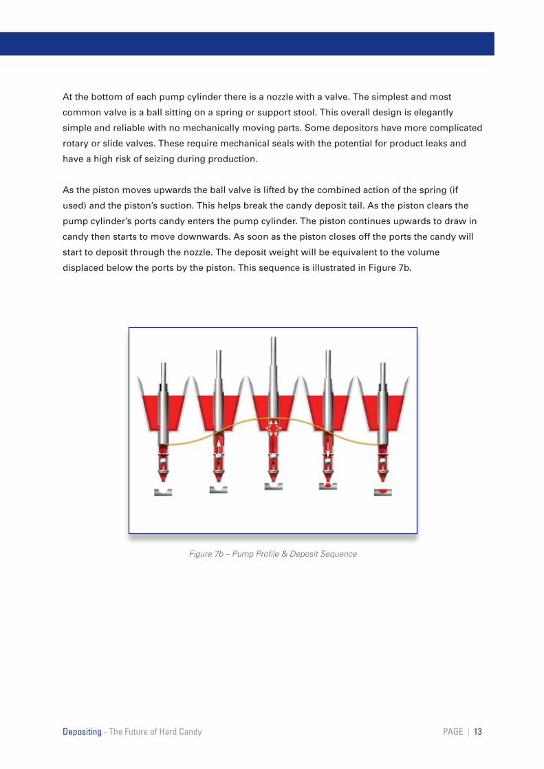
At the bottom of each pump cylinder there is a nozzle with a valve. The simplest and most
common valve is a ball sitting on a spring or support stool. This overall design is elegantly
simple and reliable with no mechanically moving parts. Some depositors have more complicated
rotary or slide valves. These require mechanical seals with the potential for product leaks and
have a high risk of seizing during production.
As the piston moves upwards the ball valve is lifted by the combined action of the spring (if
used) and the piston’s suction. This helps break the candy deposit tail. As the piston clears the
pump cylinder’s ports candy enters the pump cylinder. The piston continues upwards to draw in
candy then starts to move downwards. As soon as the piston closes off the ports the candy will
start to deposit through the nozzle. The deposit weight will be equivalent to the volume
displaced below the ports by the piston. This sequence is illustrated in Figure 7b.
PAGE | 13 Depositing - The Future of Hard Candy
Figure 7b – Pump Profile & Deposit Sequence
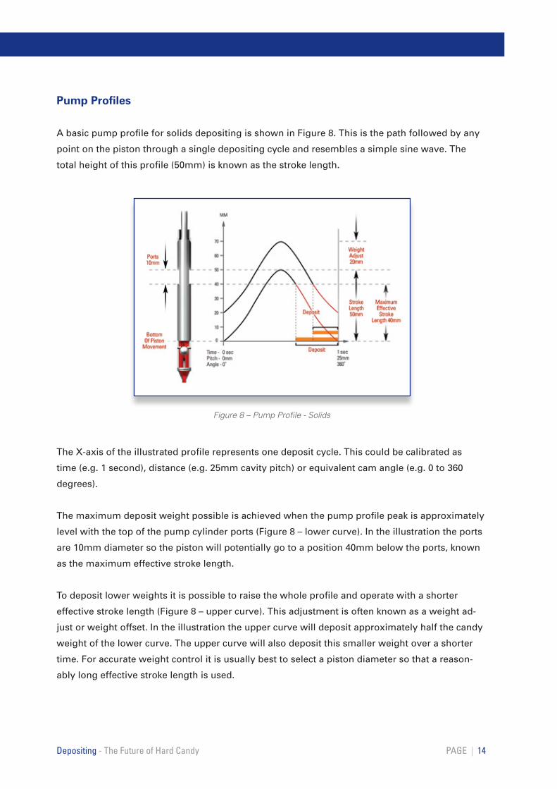
Pump Profiles
A basic pump profile for solids depositing is shown in Figure 8. This is the path followed by any
point on the piston through a single depositing cycle and resembles a simple sine wave. The
total height of this profile (50mm) is known as the stroke length.
The X-axis of the illustrated profile represents one deposit cycle. This could be calibrated as
time (e.g. 1 second), distance (e.g. 25mm cavity pitch) or equivalent cam angle (e.g. 0 to 360
degrees).
The maximum deposit weight possible is achieved when the pump profile peak is approximately
level with the top of the pump cylinder ports (Figure 8 – lower curve). In the illustration the ports
are 10mm diameter so the piston will potentially go to a position 40mm below the ports, known
as the maximum effective stroke length.
To deposit lower weights it is possible to raise the whole profile and operate with a shorter
effective stroke length (Figure 8 – upper curve). This adjustment is often known as a weight ad-
just or weight offset. In the illustration the upper curve will deposit approximately half the candy
weight of the lower curve. The upper curve will also deposit this smaller weight over a shorter
time. For accurate weight control it is usually best to select a piston diameter so that a reason-
ably long effective stroke length is used.
PAGE | 14Depositing - The Future of Hard Candy
Figure 8 – Pump Profile - Solids

A clear understanding and ability to interpret pump profiles can be very instructive when trying
to troubleshoot and improve depositing performance, or achieve a certain visual effect. Changes
can be made to the pump profile and the effect on depositing action observed. In the past this
process was very time consuming as it involved making and fitting new mechanical cams. Today,
with servo-drives, changes can be made on the run.
Deposit Weight Calculation
To select the right pistons for a product it is necessary to be able to predict what candy weight
can be deposited.
The deposit weight (W) for a specific piston diameter (D) can easily be calculated using the
piston’s displaced volume (V), candy density ( ) and pumping efficiency ( ):
Figure 9 shows the estimated maximum weight calculation for a 15mm diameter piston. This
equation can also be rearranged to predict the effective stroke length that is needed to deposit
different target weights.
PAGE | 15 Depositing - The Future of Hard Candy
Figure 9 – Deposit Weight Estimation
Nozzle Selection
Having sized the pistons the next task is to select the most appropriate nozzle.
A small diameter nozzle will produce the finest tail, but the back pressure will be high resulting
in a fast deposit velocity which may lead to the candy bouncing out of the mould cavity. Larger
diameter nozzles will produce bigger tails, but the back pressure will be less.
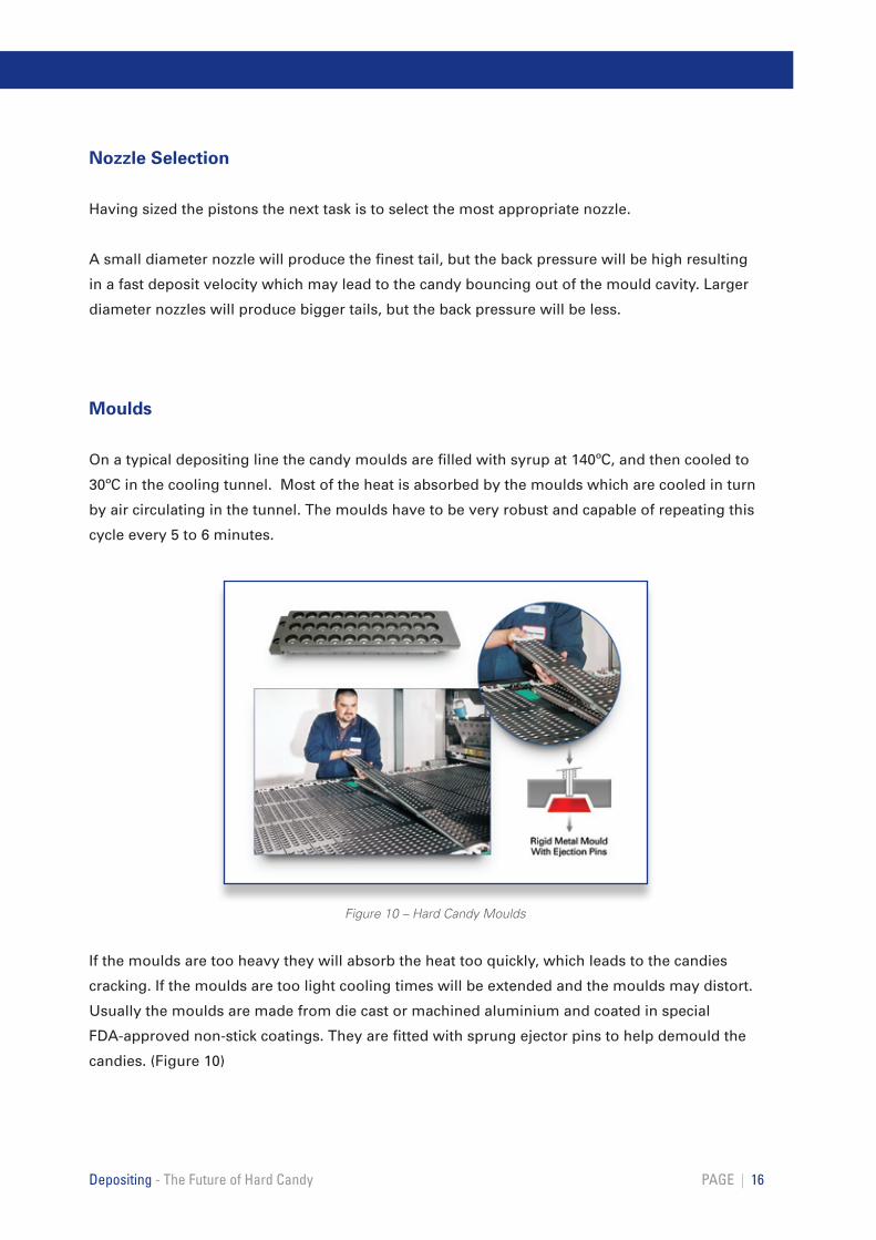
Moulds
On a typical depositing line the candy moulds are filled with syrup at 140ºC, and then cooled to
30ºC in the cooling tunnel. Most of the heat is absorbed by the moulds which are cooled in turn
by air circulating in the tunnel. The moulds have to be very robust and capable of repeating this
cycle every 5 to 6 minutes.
If the moulds are too heavy they will absorb the heat too quickly, which leads to the candies
cracking. If the moulds are too light cooling times will be extended and the moulds may distort.
Usually the moulds are made from die cast or machined aluminium and coated in special
FDA-approved non-stick coatings. They are fitted with sprung ejector pins to help demould the
candies. (Figure 10)
PAGE | 16Depositing - The Future of Hard Candy
Figure 10 – Hard Candy Moulds
Mould Lifter
At the end of the depositing stroke the nozzle valve closes to seal off the flow of syrup but a
certain amount can remain in-flight due to the viscous nature of the syrup. This trails from one
row of candies to the next and is known as a tail or ‘angel-hair’. The raw materials, recipe and
cooking process all affect the syrup viscosity and can be adjusted to reduce tailing.
Tailing can also be reduced mechanically. A mould lifter is used to raise the mould close to the
nozzle just before the deposit starts. As the deposit finishes the mould lifter drops, helping to
break any tail that forms. The timing of the mould lifter, lift height and speed can all be adjusted
to optimise performance.
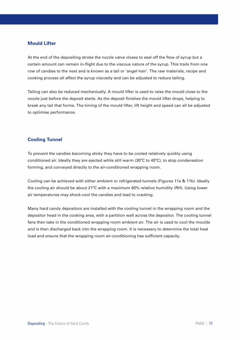
Cooling Tunnel
To prevent the candies becoming sticky they have to be cooled relatively quickly using
conditioned air. Ideally they are ejected while still warm (30ºC to 40ºC), to stop condensation
forming, and conveyed directly to the air-conditioned wrapping room.
Cooling can be achieved with either ambient or refrigerated tunnels (Figures 11a & 11b). Ideally
the cooling air should be about 21ºC with a maximum 60% relative humidity (RH). Using lower
air temperatures may shock-cool the candies and lead to cracking.
Many hard candy depositors are installed with the cooling tunnel in the wrapping room and the
depositor head in the cooking area, with a partition wall across the depositor. The cooling tunnel
fans then take in the conditioned wrapping room ambient air. The air is used to cool the moulds
and is then discharged back into the wrapping room. It is necessary to determine the total heat
load and ensure that the wrapping room air-conditioning has sufficient capacity.
PAGE | 17Depositing - The Future of Hard Candy
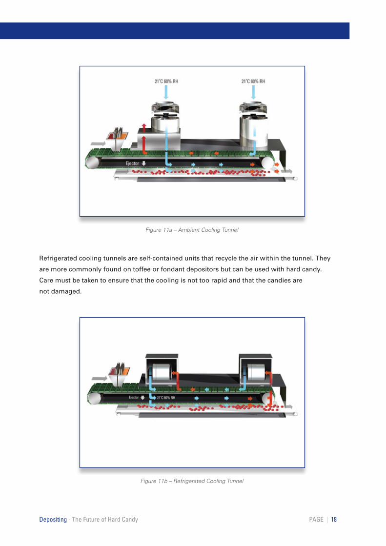
Refrigerated cooling tunnels are self-contained units that recycle the air within the tunnel. They
are more commonly found on toffee or fondant depositors but can be used with hard candy.
Care must be taken to ensure that the cooling is not too rapid and that the candies are
not damaged.
PAGE | 18Depositing - The Future of Hard Candy
Figure 11a – Ambient Cooling Tunnel
Figure 11b – Refrigerated Cooling Tunnel
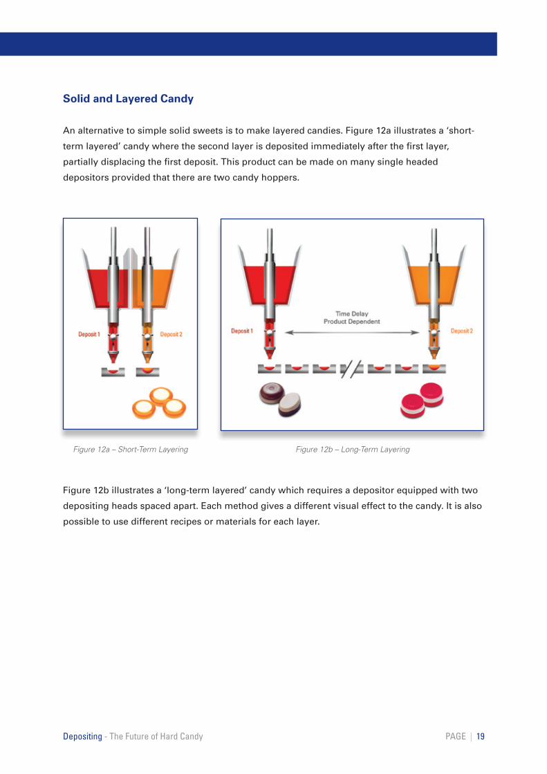
Solid and Layered Candy
An alternative to simple solid sweets is to make layered candies. Figure 12a illustrates a ‘short-
term layered’ candy where the second layer is deposited immediately after the first layer,
partially displacing the first deposit. This product can be made on many single headed
depositors provided that there are two candy hoppers.
Figure 12b illustrates a ‘long-term layered’ candy which requires a depositor equipped with two
depositing heads spaced apart. Each method gives a different visual effect to the candy. It is also
possible to use different recipes or materials for each layer.
PAGE | 19Depositing - The Future of Hard Candy
Figure 12a – Short-Term Layering Figure 12b – Long-Term Layering
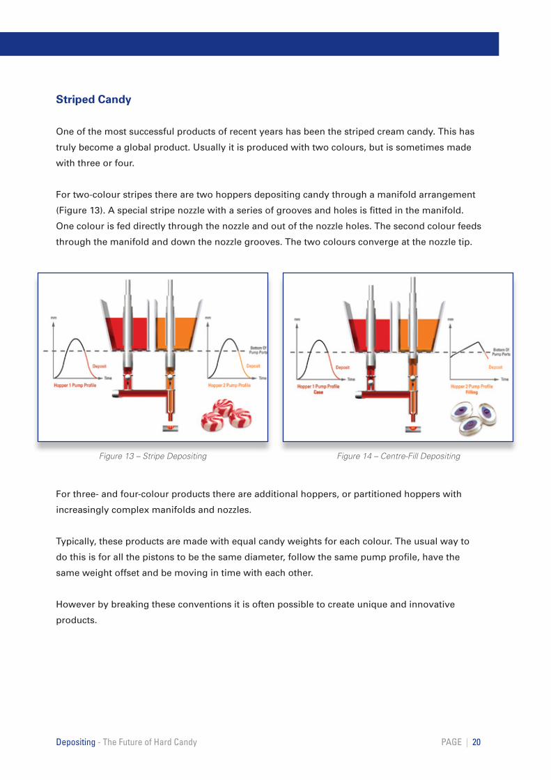
Striped Candy
One of the most successful products of recent years has been the striped cream candy. This has
truly become a global product. Usually it is produced with two colours, but is sometimes made
with three or four.
For two-colour stripes there are two hoppers depositing candy through a manifold arrangement
(Figure 13). A special stripe nozzle with a series of grooves and holes is fitted in the manifold.
One colour is fed directly through the nozzle and out of the nozzle holes. The second colour feeds
through the manifold and down the nozzle grooves. The two colours converge at the nozzle tip.
For three- and four-colour products there are additional hoppers, or partitioned hoppers with
increasingly complex manifolds and nozzles.
Typically, these products are made with equal candy weights for each colour. The usual way to
do this is for all the pistons to be the same diameter, follow the same pump profile, have the
same weight offset and be moving in time with each other.
However by breaking these conventions it is often possible to create unique and innovative
products.
PAGE | 20Depositing - The Future of Hard Candy
Figure 14 – Centre-Fill DepositingFigure 13 – Stripe Depositing
Centre-Filled Candy
A filling fully encapsulated in hard candy is an increasingly popular product option and one
that can be achieved reliably only by one-shot depositing. The easiest product to make is a
hard candy with a hard candy centre. But it is possible to centre-fill with jam, chocolate or
even caramel.
One hopper is filled with the shell, or case material: a second hopper is filled with the centre
material (Figure 14). Like stripe depositing a manifold is used to bring the two components
together. Typically the centre will be between 15% and 25% of the total candy weight.
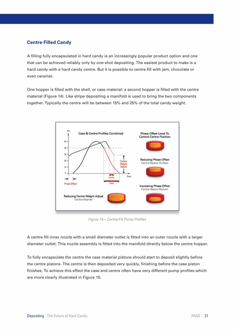
A centre-fill inner nozzle with a small diameter outlet is fitted into an outer nozzle with a larger
diameter outlet. This nozzle assembly is fitted into the manifold directly below the centre hopper.
To fully encapsulate the centre the case material pistons should start to deposit slightly before
the centre pistons. The centre is then deposited very quickly, finishing before the case piston
finishes. To achieve this effect the case and centre often have very different pump profiles which
are more clearly illustrated in Figure 15.
PAGE | 21Depositing - The Future of Hard Candy
Figure 15 – Centre-Fill Pump Profiles
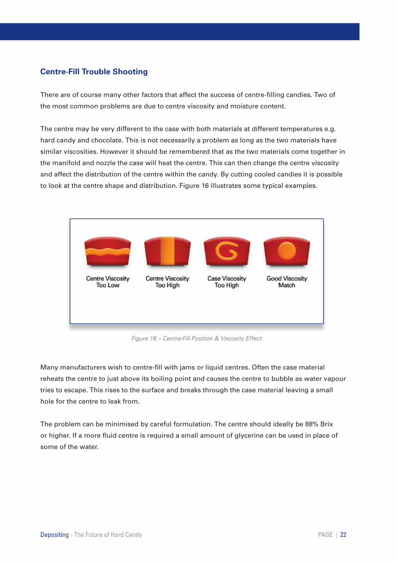
Centre-Fill Trouble Shooting
There are of course many other factors that affect the success of centre-filling candies. Two of
the most common problems are due to centre viscosity and moisture content.
The centre may be very different to the case with both materials at different temperatures e.g.
hard candy and chocolate. This is not necessarily a problem as long as the two materials have
similar viscosities. However it should be remembered that as the two materials come together in
the manifold and nozzle the case will heat the centre. This can then change the centre viscosity
and affect the distribution of the centre within the candy. By cutting cooled candies it is possible
to look at the centre shape and distribution. Figure 16 illustrates some typical examples.
Many manufacturers wish to centre-fill with jams or liquid centres. Often the case material
reheats the centre to just above its boiling point and causes the centre to bubble as water vapour
tries to escape. This rises to the surface and breaks through the case material leaving a small
hole for the centre to leak from.
The problem can be minimised by careful formulation. The centre should ideally be 88% Brix
or higher. If a more fluid centre is required a small amount of glycerine can be used in place of
some of the water.
PAGE | 22Depositing - The Future of Hard Candy
Figure 16 – Centre-Fill Position & Viscosity Effect
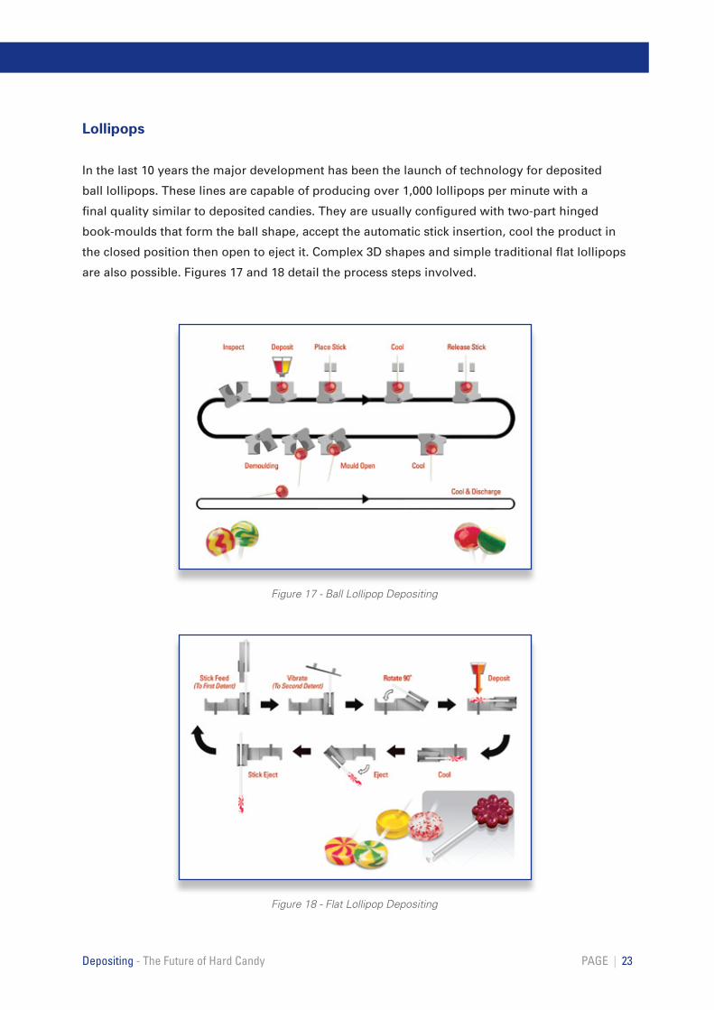
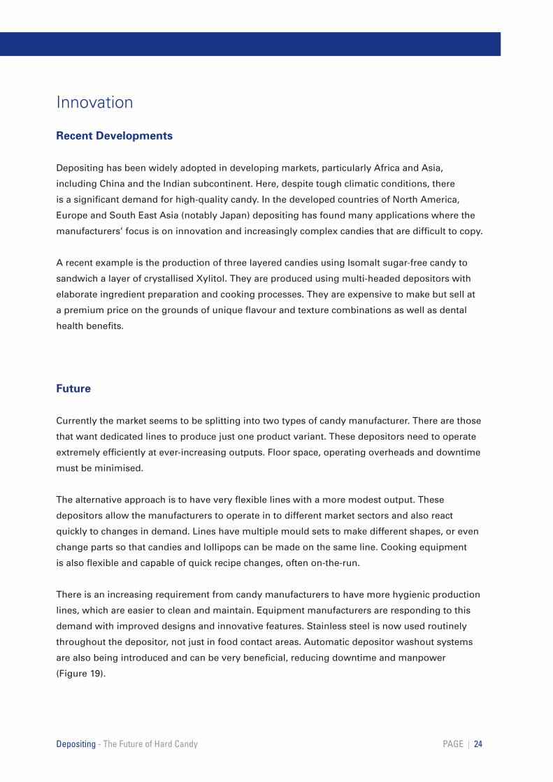
Lollipops
In the last 10 years the major development has been the launch of technology for deposited
ball lollipops. These lines are capable of producing over 1,000 lollipops per minute with a
final quality similar to deposited candies. They are usually configured with two-part hinged
book-moulds that form the ball shape, accept the automatic stick insertion, cool the product in
the closed position then open to eject it. Complex 3D shapes and simple traditional flat lollipops
are also possible. Figures 17 and 18 detail the process steps involved.
PAGE | 23Depositing - The Future of Hard Candy
Figure 17 - Ball Lollipop Depositing
Figure 18 - Flat Lollipop Depositing
Innovation
Recent Developments
Depositing has been widely adopted in developing markets, particularly Africa and Asia,
including China and the Indian subcontinent. Here, despite tough climatic conditions, there
is a significant demand for high-quality candy. In the developed countries of North America,
Europe and South East Asia (notably Japan) depositing has found many applications where the
manufacturers’ focus is on innovation and increasingly complex candies that are difficult to copy.
A recent example is the production of three layered candies using Isomalt sugar-free candy to
sandwich a layer of crystallised Xylitol. They are produced using multi-headed depositors with
elaborate ingredient preparation and cooking processes. They are expensive to make but sell at
a premium price on the grounds of unique flavour and texture combinations as well as dental
health benefits.
Future
Currently the market seems to be splitting into two types of candy manufacturer. There are those
that want dedicated lines to produce just one product variant. These depositors need to operate
extremely efficiently at ever-increasing outputs. Floor space, operating overheads and downtime
must be minimised.
The alternative approach is to have very flexible lines with a more modest output. These
depositors allow the manufacturers to operate in to different market sectors and also react
quickly to changes in demand. Lines have multiple mould sets to make different shapes, or even
change parts so that candies and lollipops can be made on the same line. Cooking equipment
is also flexible and capable of quick recipe changes, often on-the-run.
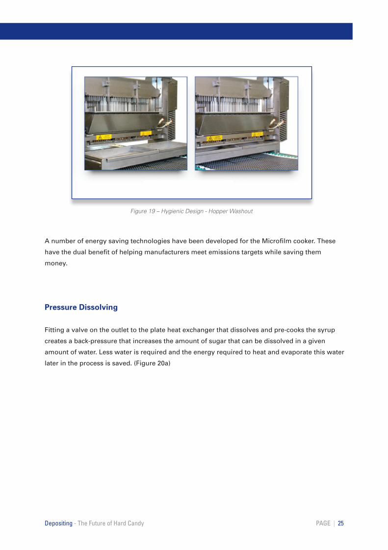
There is an increasing requirement from candy manufacturers to have more hygienic production
lines, which are easier to clean and maintain. Equipment manufacturers are responding to this
demand with improved designs and innovative features. Stainless steel is now used routinely
throughout the depositor, not just in food contact areas. Automatic depositor washout systems
are also being introduced and can be very beneficial, reducing downtime and manpower
(Figure 19).
PAGE | 24Depositing - The Future of Hard Candy
A number of energy saving technologies have been developed for the Microfilm cooker. These
have the dual benefit of helping manufacturers meet emissions targets while saving them
money.
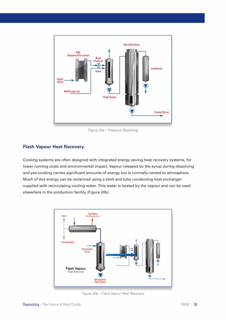
Pressure Dissolving
Fitting a valve on the outlet to the plate heat exchanger that dissolves and pre-cooks the syrup
creates a back-pressure that increases the amount of sugar that can be dissolved in a given
amount of water. Less water is required and the energy required to heat and evaporate this water
later in the process is saved. (Figure 20a)
PAGE | 25Depositing - The Future of Hard Candy
Figure 19 – Hygienic Design - Hopper Washout
PAGE | 26Depositing - The Future of Hard Candy
Figure 20a – Pressure Dissolving
Flash Vapour Heat Recovery
Cooking systems are often designed with integrated energy saving heat recovery systems, for
lower running costs and environmental impact. Vapour released by the syrup during dissolving
and pre-cooking carries significant amounts of energy but is normally vented to atmosphere.
Much of this energy can be reclaimed using a shell and tube condensing heat exchanger
supplied with recirculating cooling water. This water is heated by the vapour and can be used
elsewhere in the production facility (Figure 20b).
Figure 20b – Flash Vapour Heat Recovery
PAGE | 27Depositing - The Future of Hard Candy
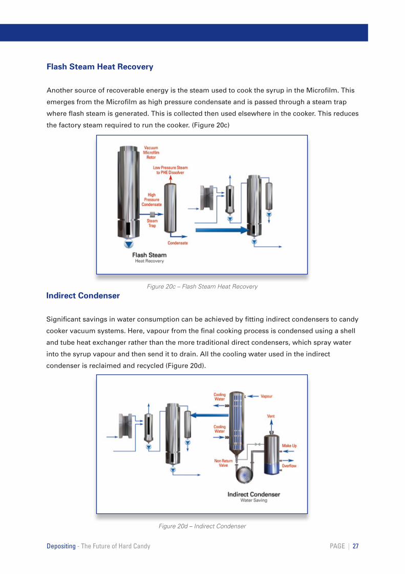
Flash Steam Heat Recovery
Another source of recoverable energy is the steam used to cook the syrup in the Microfilm. This
emerges from the Microfilm as high pressure condensate and is passed through a steam trap
where flash steam is generated. This is collected then used elsewhere in the cooker. This reduces
the factory steam required to run the cooker. (Figure 20c)
Indirect Condenser
Significant savings in water consumption can be achieved by fitting indirect condensers to candy
cooker vacuum systems. Here, vapour from the final cooking process is condensed using a shell
and tube heat exchanger rather than the more traditional direct condensers, which spray water
into the syrup vapour and then send it to drain. All the cooling water used in the indirect
condenser is reclaimed and recycled (Figure 20d).
Figure 20c – Flash Steam Heat Recovery
Figure 20d – Indirect Condenser

www.bakerperkinsgroup.com