Embed Size (px)
Citation preview

8/18/2019 Deployment Guide Sc8000
http://slidepdf.com/reader/full/deployment-guide-sc8000 1/218
Dell Compellent Storage Center™
SC8000 Controller
Deployment Guide

8/18/2019 Deployment Guide Sc8000
http://slidepdf.com/reader/full/deployment-guide-sc8000 2/218
Storage Center SC8000 Controller Deployment GuideDocument Number: 680‐087‐001
Notes, Cautions, and Warnings
Copyright Notice and Trademarks© 2014 Dell Inc.
Trademarks used in this text: Dell™, the Dell logo, and Compellent™ are trademarks of Dell Inc.
Contacting Dell Technical Support ServicesFor technical support, go to support.dell.com/compellent/ .
Revision Date Description
A July 2013 Initial release
B August 2013 Changed SSN # set up to reflect previous method, added recommended Ethernet speed, updated number of back‐end chains supported, removed references to
direct‐connect FC front‐end connection.
C December 2013 Changed number of supported chains.
D May 2014 Revise software startup procedure for SecureData and SEDs implemented in
version 6.5 software.
Note: Indicates important information that helps you complete a procedure.
Caution: Indicates either potential damage to hardware or loss of data and tells you how to avoid
the problem.
Warning: Indicates that failure to follow directions could result in property damage, personal injury, or death.

8/18/2019 Deployment Guide Sc8000
http://slidepdf.com/reader/full/deployment-guide-sc8000 3/218
Dell Compellent iii
Contents
1 Introduction . . . . . . . . . . . . . . . . . . . . . . . . . . . . . . . . . . . . . . . . . . . . . . . . 1
Storage Center Hardware Components . . . . . . . . . . . . . . . . . . . . . . . . . . . . . . . . . . . . . . . . . . . . . 2
Controllers . . . . . . . . . . . . . . . . . . . . . . . . . . . . . . . . . . . . . . . . . . . . . . . . . . . . . . . . . . . . . . . . . . . 2
Switches . . . . . . . . . . . . . . . . . . . . . . . . . . . . . . . . . . . . . . . . . . . . . . . . . . . . . . . . . . . . . . . . . . . . 2
Enclosures . . . . . . . . . . . . . . . . . . . . . . . . . . . . . . . . . . . . . . . . . . . . . . . . . . . . . . . . . . . . . . . . . . . 2
Storage Center Architecture Options . . . . . . . . . . . . . . . . . . . . . . . . . . . . . . . . . . . . . . . . . . . . . . . 3
Communication Links . . . . . . . . . . . . . . . . . . . . . . . . . . . . . . . . . . . . . . . . . . . . . . . . . . . . . . . . . . . . 4
Front End . . . . . . . . . . . . . . . . . . . . . . . . . . . . . . . . . . . . . . . . . . . . . . . . . . . . . . . . . . . . . . . . . . . . 5
Back End . . . . . . . . . . . . . . . . . . . . . . . . . . . . . . . . . . . . . . . . . . . . . . . . . . . . . . . . . . . . . . . . . . . . 5
System Administration . . . . . . . . . . . . . . . . . . . . . . . . . . . . . . . . . . . . . . . . . . . . . . . . . . . . . . . . 5
SC8000 Controller . . . . . . . . . . . . . . . . . . . . . . . . . . . . . . . . . . . . . . . . . . . . . . . . . . . . . . . . . . . . . . . . 6
SC8000 Front-Panel Features and Indicators . . . . . . . . . . . . . . . . . . . . . . . . . . . . . . . . . . . . . 7
SC8000 Back-Panel Features and Indicators . . . . . . . . . . . . . . . . . . . . . . . . . . . . . . . . . . . . . 10
SC280 SAS Enclosures . . . . . . . . . . . . . . . . . . . . . . . . . . . . . . . . . . . . . . . . . . . . . . . . . . . . . . . . . . . 12SC280 Enclosure Front Panel Features and Indicators . . . . . . . . . . . . . . . . . . . . . . . . . . . . . 13
SC280 Drawer Front-Panel Features and Indicators . . . . . . . . . . . . . . . . . . . . . . . . . . . . . . . 14
SC280 Back-Panel Features and Indicators . . . . . . . . . . . . . . . . . . . . . . . . . . . . . . . . . . . . . . 15
SC280 EMM Features and Indicators . . . . . . . . . . . . . . . . . . . . . . . . . . . . . . . . . . . . . . . . . . . . 16
SC280 Power Supply Unit Features and Indicators . . . . . . . . . . . . . . . . . . . . . . . . . . . . . . . . 17
Fan Module Features and Indicators . . . . . . . . . . . . . . . . . . . . . . . . . . . . . . . . . . . . . . . . . . . . 18
SC280 Enterprise Plus Drives . . . . . . . . . . . . . . . . . . . . . . . . . . . . . . . . . . . . . . . . . . . . . . . . . . . 19
SC280 Drive Numbering . . . . . . . . . . . . . . . . . . . . . . . . . . . . . . . . . . . . . . . . . . . . . . . . . . . . . . . 20
SC200/220 SAS Enclosures . . . . . . . . . . . . . . . . . . . . . . . . . . . . . . . . . . . . . . . . . . . . . . . . . . . . . . . 20
SC200/220 Front-Panel Features and Indicators . . . . . . . . . . . . . . . . . . . . . . . . . . . . . . . . . . . 21
SC200/220 Back-Panel Features and Indicators . . . . . . . . . . . . . . . . . . . . . . . . . . . . . . . . . . . 22
SC200/220 EMM Features and Indicators . . . . . . . . . . . . . . . . . . . . . . . . . . . . . . . . . . . . . . . . 23
SC200/220 Enterprise Plus Drives . . . . . . . . . . . . . . . . . . . . . . . . . . . . . . . . . . . . . . . . . . . . . . . 24
SC200/220 Drive Numbering . . . . . . . . . . . . . . . . . . . . . . . . . . . . . . . . . . . . . . . . . . . . . . . . . . . . 25

8/18/2019 Deployment Guide Sc8000
http://slidepdf.com/reader/full/deployment-guide-sc8000 4/218
iv Storage Center SC8000 Controller Deployment Guide
Contents
EN-SASx6x12/24 Enclosures . . . . . . . . . . . . . . . . . . . . . . . . . . . . . . . . . . . . . . . . . . . . . . . . . . . . . . 26
EN-SASx6x12/24 Front-Panel Features and Indicators . . . . . . . . . . . . . . . . . . . . . . . . . . . . . 26
EN-SASx6x12/24 Back-Panel Features and Indicators . . . . . . . . . . . . . . . . . . . . . . . . . . . . . 27
EN-SASx6x12/24 SBB Module Features and Indicators . . . . . . . . . . . . . . . . . . . . . . . . . . . . 28
EN-SASx6x12/24 Standard SAS Drives . . . . . . . . . . . . . . . . . . . . . . . . . . . . . . . . . . . . . . . . . . 29EN-SASx6x12/24 Drive Numbering . . . . . . . . . . . . . . . . . . . . . . . . . . . . . . . . . . . . . . . . . . . . . . 30
2 Install the Hardware . . . . . . . . . . . . . . . . . . . . . . . . . . . . . . . . . . . . . . . . 31
Prepare for Installation . . . . . . . . . . . . . . . . . . . . . . . . . . . . . . . . . . . . . . . . . . . . . . . . . . . . . . . . . . . 31
Unpack and Inventory the Storage Center Equipment . . . . . . . . . . . . . . . . . . . . . . . . . . . . . 31
Prepare the Installation Environment . . . . . . . . . . . . . . . . . . . . . . . . . . . . . . . . . . . . . . . . . . . . 31
Gather Required Materials . . . . . . . . . . . . . . . . . . . . . . . . . . . . . . . . . . . . . . . . . . . . . . . . . . . . . 32
Safety Precautions . . . . . . . . . . . . . . . . . . . . . . . . . . . . . . . . . . . . . . . . . . . . . . . . . . . . . . . . . . . . . . 32
Electrical Safety Precautions . . . . . . . . . . . . . . . . . . . . . . . . . . . . . . . . . . . . . . . . . . . . . . . . . . . 32
General Safety Precautions . . . . . . . . . . . . . . . . . . . . . . . . . . . . . . . . . . . . . . . . . . . . . . . . . . . . 33
Electrostatic Discharge Precautions . . . . . . . . . . . . . . . . . . . . . . . . . . . . . . . . . . . . . . . . . . . . 34
Install IO Cards the Controller(s) . . . . . . . . . . . . . . . . . . . . . . . . . . . . . . . . . . . . . . . . . . . . . . . . . . . 35
Open the Cover . . . . . . . . . . . . . . . . . . . . . . . . . . . . . . . . . . . . . . . . . . . . . . . . . . . . . . . . . . . . . . . 35
Install IO Cards . . . . . . . . . . . . . . . . . . . . . . . . . . . . . . . . . . . . . . . . . . . . . . . . . . . . . . . . . . . . . . . 37
Close the Cover . . . . . . . . . . . . . . . . . . . . . . . . . . . . . . . . . . . . . . . . . . . . . . . . . . . . . . . . . . . . . . . 43
Label the Controllers . . . . . . . . . . . . . . . . . . . . . . . . . . . . . . . . . . . . . . . . . . . . . . . . . . . . . . . . . . . . . 44
Mount the Hardware in a Rack . . . . . . . . . . . . . . . . . . . . . . . . . . . . . . . . . . . . . . . . . . . . . . . . . . . . 452U and 3U Enclosures . . . . . . . . . . . . . . . . . . . . . . . . . . . . . . . . . . . . . . . . . . . . . . . . . . . . . . . . . 45
5U Enclosures . . . . . . . . . . . . . . . . . . . . . . . . . . . . . . . . . . . . . . . . . . . . . . . . . . . . . . . . . . . . . . . . 46
Install Drives in SC280 Enclosures . . . . . . . . . . . . . . . . . . . . . . . . . . . . . . . . . . . . . . . . . . . . . . . . . 48
Installing Drives . . . . . . . . . . . . . . . . . . . . . . . . . . . . . . . . . . . . . . . . . . . . . . . . . . . . . . . . . . . . . . 48
Install Drives in EN-SASx6x12/24 Enclosures . . . . . . . . . . . . . . . . . . . . . . . . . . . . . . . . . . . . . . . . 50
Installing 3.5" Drives . . . . . . . . . . . . . . . . . . . . . . . . . . . . . . . . . . . . . . . . . . . . . . . . . . . . . . . . . . . 50
Installing 2.5" Drives . . . . . . . . . . . . . . . . . . . . . . . . . . . . . . . . . . . . . . . . . . . . . . . . . . . . . . . . . . . 52
Install Enterprise Plus Drives in SC200/220 Enclosures . . . . . . . . . . . . . . . . . . . . . . . . . . . . . . . 53
3 Connect the Back End . . . . . . . . . . . . . . . . . . . . . . . . . . . . . . . . . . . . . . . 55
SAS Enclosure Cabling Guidelines . . . . . . . . . . . . . . . . . . . . . . . . . . . . . . . . . . . . . . . . . . . . . . . . . 55
SAS Redundancy . . . . . . . . . . . . . . . . . . . . . . . . . . . . . . . . . . . . . . . . . . . . . . . . . . . . . . . . . . . . . 55
SC8000 SAS Port Types . . . . . . . . . . . . . . . . . . . . . . . . . . . . . . . . . . . . . . . . . . . . . . . . . . . . . . . . 56

8/18/2019 Deployment Guide Sc8000
http://slidepdf.com/reader/full/deployment-guide-sc8000 5/218
Dell Compellent v
Contents
Connect IPC for Dual-Controller Storage Centers . . . . . . . . . . . . . . . . . . . . . . . . . . . . . . . . . . . . 56
Connect the Controllers with Ethernet . . . . . . . . . . . . . . . . . . . . . . . . . . . . . . . . . . . . . . . . . . . 57
Connect the Controllers with SAS . . . . . . . . . . . . . . . . . . . . . . . . . . . . . . . . . . . . . . . . . . . . . . . 59
Connect SC200/SC220 Enclosures . . . . . . . . . . . . . . . . . . . . . . . . . . . . . . . . . . . . . . . . . . . . . . . . . 60
Single Controller, Single Enclosure, Low Profile SAS . . . . . . . . . . . . . . . . . . . . . . . . . . . . . . 61Single Controller, Single Enclosure . . . . . . . . . . . . . . . . . . . . . . . . . . . . . . . . . . . . . . . . . . . . . . 62
Single Controller, Four Enclosures, Single Chain, Low Profile SAS . . . . . . . . . . . . . . . . . . 63
Single Controller, Four Enclosures, Single Chain . . . . . . . . . . . . . . . . . . . . . . . . . . . . . . . . . . 64
Single Controller, Four Enclosures, Two IO Cards, Two Chains, Low Profile SAS . . . . . . 65
Single Controller, Four Enclosures, Two IO Cards, Two Chains . . . . . . . . . . . . . . . . . . . . . . 66
Dual Controllers, One Enclosure, Single Chain, Low Profile SAS . . . . . . . . . . . . . . . . . . . . 67
Dual Controllers, One Enclosure, Single Chain . . . . . . . . . . . . . . . . . . . . . . . . . . . . . . . . . . . . 68
Dual Controllers, Two Enclosures, Single Chain, Low Profile SAS . . . . . . . . . . . . . . . . . . . 69
Dual Controllers, Two Enclosures, Single Chain . . . . . . . . . . . . . . . . . . . . . . . . . . . . . . . . . . . 70
Dual Controllers, Four Enclosures, Two Chains, Low Profile SAS . . . . . . . . . . . . . . . . . . . . 71
Dual Controllers, Four Enclosures, Two Chains . . . . . . . . . . . . . . . . . . . . . . . . . . . . . . . . . . . 73
Dual Controllers, Eight Enclosures, Two Chains . . . . . . . . . . . . . . . . . . . . . . . . . . . . . . . . . . . 74
Connect SC280 Enclosures . . . . . . . . . . . . . . . . . . . . . . . . . . . . . . . . . . . . . . . . . . . . . . . . . . . . . . . 75
Single Controller, Single SC280 Enclosure . . . . . . . . . . . . . . . . . . . . . . . . . . . . . . . . . . . . . . . . 76
Single Controller, Two SC280 Enclosures . . . . . . . . . . . . . . . . . . . . . . . . . . . . . . . . . . . . . . . . 77
Dual Controller, Single SC280 Enclosure . . . . . . . . . . . . . . . . . . . . . . . . . . . . . . . . . . . . . . . . . 78
Dual Controller, Two SC280 Enclosures . . . . . . . . . . . . . . . . . . . . . . . . . . . . . . . . . . . . . . . . . . 79Dual Controllers, Two SC280 and Two SC200/SC220 Enclosures, Two Chains . . . . . . . . . 81
Connect EN-SASx6x12/24 Enclosures . . . . . . . . . . . . . . . . . . . . . . . . . . . . . . . . . . . . . . . . . . . . . . 84
Single Controller, Single Enclosure . . . . . . . . . . . . . . . . . . . . . . . . . . . . . . . . . . . . . . . . . . . . . . 85
Single Controller, Four Enclosures, Single Chain . . . . . . . . . . . . . . . . . . . . . . . . . . . . . . . . . . 86
Single Controller, Four Enclosures, Two IO Cards, Two Chains . . . . . . . . . . . . . . . . . . . . . . 87
Dual Controllers, Two Enclosures, Single Chain . . . . . . . . . . . . . . . . . . . . . . . . . . . . . . . . . . . 88
Dual Controllers, Four Enclosures, Single Chain . . . . . . . . . . . . . . . . . . . . . . . . . . . . . . . . . . 90
Label the Back-End Cables . . . . . . . . . . . . . . . . . . . . . . . . . . . . . . . . . . . . . . . . . . . . . . . . . . . . . . . 93
4 Connect the Front End . . . . . . . . . . . . . . . . . . . . . . . . . . . . . . . . . . . . . . . 95
Types of Redundancy for Front-End Connections . . . . . . . . . . . . . . . . . . . . . . . . . . . . . . . . . . . . 95
Multipath IO . . . . . . . . . . . . . . . . . . . . . . . . . . . . . . . . . . . . . . . . . . . . . . . . . . . . . . . . . . . . . . . . . . . . 96
MPIO Behavior for Dual-Controller Storage Centers . . . . . . . . . . . . . . . . . . . . . . . . . . . . . . . 96
MPIO Configuration Instructions for Servers . . . . . . . . . . . . . . . . . . . . . . . . . . . . . . . . . . . . . 96

8/18/2019 Deployment Guide Sc8000
http://slidepdf.com/reader/full/deployment-guide-sc8000 6/218
vi Storage Center SC8000 Controller Deployment Guide
Contents
Front-End Connectivity Modes . . . . . . . . . . . . . . . . . . . . . . . . . . . . . . . . . . . . . . . . . . . . . . . . . . . . 96
Virtual Port Mode . . . . . . . . . . . . . . . . . . . . . . . . . . . . . . . . . . . . . . . . . . . . . . . . . . . . . . . . . . . . . 97
Legacy Mode . . . . . . . . . . . . . . . . . . . . . . . . . . . . . . . . . . . . . . . . . . . . . . . . . . . . . . . . . . . . . . . . 99
Failover Behavior for Legacy Mode and Virtual Port Mode . . . . . . . . . . . . . . . . . . . . . . . . . 101
Fibre Channel Zoning . . . . . . . . . . . . . . . . . . . . . . . . . . . . . . . . . . . . . . . . . . . . . . . . . . . . . . . . . . . . 102WWN Zoning Guidelines . . . . . . . . . . . . . . . . . . . . . . . . . . . . . . . . . . . . . . . . . . . . . . . . . . . . . . . 102
Port Zoning Guidelines . . . . . . . . . . . . . . . . . . . . . . . . . . . . . . . . . . . . . . . . . . . . . . . . . . . . . . . . 102
Connect the Front End for a Single-Controller Storage Center . . . . . . . . . . . . . . . . . . . . . . . . . 103
Connect Servers to a Single Controller with No Redundancy . . . . . . . . . . . . . . . . . . . . . . . 103
Connect Servers to a Single Controller with Redundancy . . . . . . . . . . . . . . . . . . . . . . . . . . 104
Connect the Front End for a Dual-Controller Storage Center . . . . . . . . . . . . . . . . . . . . . . . . . . 105
Connect Fibre Channel Servers . . . . . . . . . . . . . . . . . . . . . . . . . . . . . . . . . . . . . . . . . . . . . . . . . 105
Connect iSCSI Servers . . . . . . . . . . . . . . . . . . . . . . . . . . . . . . . . . . . . . . . . . . . . . . . . . . . . . . . . 111
Label the Front-End Cables . . . . . . . . . . . . . . . . . . . . . . . . . . . . . . . . . . . . . . . . . . . . . . . . . . . . . . . 116
5 Set up the Storage Center Software . . . . . . . . . . . . . . . . . . . . . . . . . . . 119
Prerequisites . . . . . . . . . . . . . . . . . . . . . . . . . . . . . . . . . . . . . . . . . . . . . . . . . . . . . . . . . . . . . . . . . . . 119
Hardware Configuration . . . . . . . . . . . . . . . . . . . . . . . . . . . . . . . . . . . . . . . . . . . . . . . . . . . . . . . 119
Required Materials . . . . . . . . . . . . . . . . . . . . . . . . . . . . . . . . . . . . . . . . . . . . . . . . . . . . . . . . . . . 120
Required Documents . . . . . . . . . . . . . . . . . . . . . . . . . . . . . . . . . . . . . . . . . . . . . . . . . . . . . . . . . . 120
Required Software Versions . . . . . . . . . . . . . . . . . . . . . . . . . . . . . . . . . . . . . . . . . . . . . . . . . . . 120
Connect the Ethernet Management and iDRAC Interfaces . . . . . . . . . . . . . . . . . . . . . . . . . . . . 121Connect Single-Controller Management Ports . . . . . . . . . . . . . . . . . . . . . . . . . . . . . . . . . . . . 121
Connect Dual-Controller Management Ports . . . . . . . . . . . . . . . . . . . . . . . . . . . . . . . . . . . . . 122
Label the Management Cables . . . . . . . . . . . . . . . . . . . . . . . . . . . . . . . . . . . . . . . . . . . . . . . . . 122
Turn on the Hardware . . . . . . . . . . . . . . . . . . . . . . . . . . . . . . . . . . . . . . . . . . . . . . . . . . . . . . . . . . . . 124
Configure the Controller(s) . . . . . . . . . . . . . . . . . . . . . . . . . . . . . . . . . . . . . . . . . . . . . . . . . . . . . . . . 124
Reset Hardware and System Serial Numbers . . . . . . . . . . . . . . . . . . . . . . . . . . . . . . . . . . . . . 124
Set Controller IP Addresses . . . . . . . . . . . . . . . . . . . . . . . . . . . . . . . . . . . . . . . . . . . . . . . . . . . . 125
Manage the iDRAC IP Address . . . . . . . . . . . . . . . . . . . . . . . . . . . . . . . . . . . . . . . . . . . . . . . . . 126
Verify Software Support for Enclosures . . . . . . . . . . . . . . . . . . . . . . . . . . . . . . . . . . . . . . . . . . . . 127
Start the Storage Center Startup Wizard . . . . . . . . . . . . . . . . . . . . . . . . . . . . . . . . . . . . . . . . . . . . 128
Complete the Startup Wizard . . . . . . . . . . . . . . . . . . . . . . . . . . . . . . . . . . . . . . . . . . . . . . . . . . . . . . 129
License Agreement . . . . . . . . . . . . . . . . . . . . . . . . . . . . . . . . . . . . . . . . . . . . . . . . . . . . . . . . . . . 129
Load the License File . . . . . . . . . . . . . . . . . . . . . . . . . . . . . . . . . . . . . . . . . . . . . . . . . . . . . . . . . . 130
Create a Disk Folder . . . . . . . . . . . . . . . . . . . . . . . . . . . . . . . . . . . . . . . . . . . . . . . . . . . . . . . . . . . 132

8/18/2019 Deployment Guide Sc8000
http://slidepdf.com/reader/full/deployment-guide-sc8000 7/218
Dell Compellent vii
Contents
Add a Controller . . . . . . . . . . . . . . . . . . . . . . . . . . . . . . . . . . . . . . . . . . . . . . . . . . . . . . . . . . . . . . 136
Set the Time . . . . . . . . . . . . . . . . . . . . . . . . . . . . . . . . . . . . . . . . . . . . . . . . . . . . . . . . . . . . . . . . . 138
Set the System IP Address . . . . . . . . . . . . . . . . . . . . . . . . . . . . . . . . . . . . . . . . . . . . . . . . . . . . . 139
Configure a Key Management Server . . . . . . . . . . . . . . . . . . . . . . . . . . . . . . . . . . . . . . . . . . . 141
Configure SMTP . . . . . . . . . . . . . . . . . . . . . . . . . . . . . . . . . . . . . . . . . . . . . . . . . . . . . . . . . . . . . . 142Select Update Option . . . . . . . . . . . . . . . . . . . . . . . . . . . . . . . . . . . . . . . . . . . . . . . . . . . . . . . . . . 144
Set Admin Account . . . . . . . . . . . . . . . . . . . . . . . . . . . . . . . . . . . . . . . . . . . . . . . . . . . . . . . . . . . 145
Configure IO Cards . . . . . . . . . . . . . . . . . . . . . . . . . . . . . . . . . . . . . . . . . . . . . . . . . . . . . . . . . . . . 146
Configure Ports . . . . . . . . . . . . . . . . . . . . . . . . . . . . . . . . . . . . . . . . . . . . . . . . . . . . . . . . . . . . . . . 147
Generate SSL Certificate . . . . . . . . . . . . . . . . . . . . . . . . . . . . . . . . . . . . . . . . . . . . . . . . . . . . . . 160
Label SC200 and SC220 Enclosures . . . . . . . . . . . . . . . . . . . . . . . . . . . . . . . . . . . . . . . . . . . . . . . . 163
6 Perform Post-Setup Tasks . . . . . . . . . . . . . . . . . . . . . . . . . . . . . . . . . . . 165
Verify Connectivity and Failover . . . . . . . . . . . . . . . . . . . . . . . . . . . . . . . . . . . . . . . . . . . . . . . . . . . 165
Create Test Volumes . . . . . . . . . . . . . . . . . . . . . . . . . . . . . . . . . . . . . . . . . . . . . . . . . . . . . . . . . . 165
Test Connectivity and Failover . . . . . . . . . . . . . . . . . . . . . . . . . . . . . . . . . . . . . . . . . . . . . . . . . . 166
Clean up Test Volumes . . . . . . . . . . . . . . . . . . . . . . . . . . . . . . . . . . . . . . . . . . . . . . . . . . . . . . . . 167
Change Administrative Passwords . . . . . . . . . . . . . . . . . . . . . . . . . . . . . . . . . . . . . . . . . . . . . . . . . 168
Configure a Phone Home Proxy . . . . . . . . . . . . . . . . . . . . . . . . . . . . . . . . . . . . . . . . . . . . . . . . . . . 170
Phone Home . . . . . . . . . . . . . . . . . . . . . . . . . . . . . . . . . . . . . . . . . . . . . . . . . . . . . . . . . . . . . . . . . . . . 170
Check for Storage Center Updates . . . . . . . . . . . . . . . . . . . . . . . . . . . . . . . . . . . . . . . . . . . . . . . . . 172
Next Steps . . . . . . . . . . . . . . . . . . . . . . . . . . . . . . . . . . . . . . . . . . . . . . . . . . . . . . . . . . . . . . . . . . . . . . 172
A Adding or Removing an Enclosure . . . . . . . . . . . . . . . . . . . . . . . . . . . . 173
Adding SC280 Enclosures . . . . . . . . . . . . . . . . . . . . . . . . . . . . . . . . . . . . . . . . . . . . . . . . . . . . . . . . . 174
Adding an SC280 Enclosure in a New Chain . . . . . . . . . . . . . . . . . . . . . . . . . . . . . . . . . . . . . . 174
Adding to an Existing SC280 Enclosure Chain . . . . . . . . . . . . . . . . . . . . . . . . . . . . . . . . . . . . . 178
Adding SC200/220 Enclosures . . . . . . . . . . . . . . . . . . . . . . . . . . . . . . . . . . . . . . . . . . . . . . . . . . . . . 184
Creating a New Chain of SC200/220 Enclosures . . . . . . . . . . . . . . . . . . . . . . . . . . . . . . . . . . . 184
Adding to an Existing SAS Enclosure Chain . . . . . . . . . . . . . . . . . . . . . . . . . . . . . . . . . . . . . . 186Adding a Second SAS Enclosure, Second Chain . . . . . . . . . . . . . . . . . . . . . . . . . . . . . . . . . . 191
Removing Enclosures . . . . . . . . . . . . . . . . . . . . . . . . . . . . . . . . . . . . . . . . . . . . . . . . . . . . . . . . . . . . 193
Release Disks . . . . . . . . . . . . . . . . . . . . . . . . . . . . . . . . . . . . . . . . . . . . . . . . . . . . . . . . . . . . . . . . 193
Remove an SC280 Enclosure . . . . . . . . . . . . . . . . . . . . . . . . . . . . . . . . . . . . . . . . . . . . . . . . . . . 193
Remove an SC200/SC220 Enclosure . . . . . . . . . . . . . . . . . . . . . . . . . . . . . . . . . . . . . . . . . . . . . 199

8/18/2019 Deployment Guide Sc8000
http://slidepdf.com/reader/full/deployment-guide-sc8000 8/218
viii Storage Center SC8000 Controller Deployment Guide
Contents
B Troubleshooting . . . . . . . . . . . . . . . . . . . . . . . . . . . . . . . . . . . . . . . . . . . . 205
Troubleshooting the Serial Connection . . . . . . . . . . . . . . . . . . . . . . . . . . . . . . . . . . . . . . . . . . . . . 205
Troubleshooting Enclosures . . . . . . . . . . . . . . . . . . . . . . . . . . . . . . . . . . . . . . . . . . . . . . . . . . . . . . 205
Troubleshooting Licenses . . . . . . . . . . . . . . . . . . . . . . . . . . . . . . . . . . . . . . . . . . . . . . . . . . . . . . . . 206
Troubleshooting Updates . . . . . . . . . . . . . . . . . . . . . . . . . . . . . . . . . . . . . . . . . . . . . . . . . . . . . . . . . 206

8/18/2019 Deployment Guide Sc8000
http://slidepdf.com/reader/full/deployment-guide-sc8000 9/218
Dell Compellent ix
Preface
The preface introduces you to the Storage Center documentation. It provides the purpose and audience of this document as well as a list of related publications.
PurposeThe Storage Center SC8000
Controller
Deployment
Guide provides cabling instructions for Storage Center
controllers, switches, and enclosures and provides instructions for configuring a new Dell Compellent Storage Center using the System Manager Startup wizard.
AudienceTarget audiences for this document are Dell installers and Dell business partners. The intended reader has
a working knowledge of storage concepts.
Related PublicationsThe following documents comprise the core Storage Center documentation set:
Storage
Center
Release
Notes
Contains information about features and open and resolved issues for a particular product version.
Storage
Center
System
Manager
Administrator’s
Guide
Describes the Storage Center System Manager software that manages an individual Storage Center.
Storage
Center
Software
Update
Guide
Describes how to upgrade Storage Center software from an earlier version to the current version.
Storage
Center
Maintenance
CD
Instructions
Describes how to install Storage Center software on Storage Center controllers. Installing Storage Center software using the Storage Center Maintenance CD is intended for use only by sites that cannot update
Storage Center using the standard update options available through the Storage Center System
Manager.
Storage
Center
Command
Utility
Reference
GuideProvides instructions for using the Storage Center Command Utility. The Command Utility provides a
command‐line interface (CLI) to enable management of Storage Center functionality on Windows, Linux, Solaris, and AIX platforms.
Storage
Center
Command
Set
for
Windows
PowerShell
Provides instructions for getting started with Windows PowerShell cmdlets and scripting objects that interact with the Storage Center via the PowerShell interactive shell, scripts, and PowerShell hosting
applications. Help for individual cmdlets is available online.

8/18/2019 Deployment Guide Sc8000
http://slidepdf.com/reader/full/deployment-guide-sc8000 10/218
x Storage Center SC8000 Controller Deployment Guide
Dell
TechCenter
Provides technical white papers, best practice guides, and frequently asked questions about Dell Storage products. Go to: http://en.community.dell.com/techcenter/storage/ and select Dell Compellent in the Table of Contents.
8/18/2019 Deployment Guide Sc8000
http://slidepdf.com/reader/full/deployment-guide-sc8000 11/218
Dell Compellent 1
1 Introduction
The Storage Center SC8000
Controller
Deployment
Guide describes how to install and
configure Dell Compellent Storage Center. The information provided in this Deployment Guide is intended to be used by Dell installers and Dell business partners.
ContentsStorage Center Hardware Components . . . . . . . . . . . . . . . . . . . . . . . . . . . . . . . . . . . . . . . . . . 2
Storage Center Architecture Options . . . . . . . . . . . . . . . . . . . . . . . . . . . . . . . . . . . . . . . . . . . . 3
Communication Links . . . . . . . . . . . . . . . . . . . . . . . . . . . . . . . . . . . . . . . . . . . . . . . . . . . . . . . . 4
SC8000 Controller . . . . . . . . . . . . . . . . . . . . . . . . . . . . . . . . . . . . . . . . . . . . . . . . . . . . . . . . . . . . 6
SC280 SAS Enclosures . . . . . . . . . . . . . . . . . . . . . . . . . . . . . . . . . . . . . . . . . . . . . . . . . . . . . . . 12
SC200/220 SAS Enclosures . . . . . . . . . . . . . . . . . . . . . . . . . . . . . . . . . . . . . . . . . . . . . . . . . . . . 20
EN‐SASx6x12/24 Enclosures . . . . . . . . . . . . . . . . . . . . . . . . . . . . . . . . . . . . . . . . . . . . . . . . . . 26

8/18/2019 Deployment Guide Sc8000
http://slidepdf.com/reader/full/deployment-guide-sc8000 12/218
Chapter 1 Introduction
2 Storage Center SC8000 Controller Deployment Guide
Storage Center Hardware ComponentsA Dell Compellent Storage Center consists of one or two controllers, switches, and one or more enclosures.
ControllersA Storage Center controller provides the central processing capability for the Storage
Center Operating System (OS), application software (Storage Center System Manager), and
managing RAID storage. A Storage Center can be configured with a single controller (single‐controller Storage Center) or a pair of controllers (dual‐controller Storage Center). In a dual‐controller Storage Center configuration, the pair of controllers must be the same
controller model.
IO cards in the controller provide communication with drive enclosures and servers that use the storage. Controllers provide two types of IO ports:
Front‐end ports: Hosts, servers, or Network Attached Storage (NAS) appliances access storage by connecting to controller Fibre Channel IO cards, FCoE IO cards, or iSCSI IO
cards through one or more Fibre Channel or Ethernet network switches. Ports for these
connections are located on the back of the controller, but are designated as front‐end
ports.
Back‐end ports: Enclosures, which hold the physical drives that provide back‐end
storage, connect directly to the controller. Fibre Channel and SAS transports are
supported through ports designated as back‐end ports. Back‐end ports are in their own
private network between the controllers and the drive enclosures.
SwitchesDell Compellent offers Fibre Channel (FC) and iSCSI switches and IO cards as part of the
total Storage Center product package. Switches provide robust connectivity to servers, allowing for the use of multiple controllers and redundant transport paths. Cabling
between the controller IO cards and switches (and servers) is referred to as front‐end
connectivity.
EnclosuresEnclosures house and control drives that provide storage. Enclosures are connected
directly to controller IO cards. These connections are referred to as back‐end connectivity.
New Storage Center deployments use 6 GB Serial Attached SCSI (SAS) disk enclosures.
Fibre Channel Switched Bunch of Disks (SBOD) and Serial Advanced Technology
Attachment (SATA) enclosures are supported for existing Storage Centers and for controller migrations only (for example, upgrading an existing Storage Center by
migrating from a CT‐SC040 controller to an SC8000 controller).

8/18/2019 Deployment Guide Sc8000
http://slidepdf.com/reader/full/deployment-guide-sc8000 13/218
Storage Center Architecture Options
Dell Compellent 3
Storage Center Architecture OptionsThe Dell Compellent Storage Center can be deployed in a variety of configurations:
Single Controller, Single Enclosure
Single Controller, Multiple Enclosures
Dual Controller, Single Enclosure
Dual Controller, Multiple Enclosures
Figure 1. Storage Center Architectures
Additionally, Storage Center sites can be co‐located or remotely connected and continue to
share and replicate data between sites. Replication is used to duplicate volume data to support a Disaster Recovery Plan or to provide rapid local access to a remote data volume. Typically, data is replicated remotely to safeguard against local or even regional data
threats as part of an overall Disaster Recovery Plan.

8/18/2019 Deployment Guide Sc8000
http://slidepdf.com/reader/full/deployment-guide-sc8000 14/218
Chapter 1 Introduction
4 Storage Center SC8000 Controller Deployment Guide
Communication LinksA Storage Center controller uses multiple types of communication links for both data
transfer and administrative functions. Communication links are classified into three types: front end, back end, and system administration.
Figure 2. SC8000 Controller Communication Links
Item Description Speed Type
1 Server with Fibre Channel Host Bus Adapters (HBAs)
8 Gb or 16 Gb Front End
2 Fibre Channel Switches 8 Gb or 16 Gb Front End
3 Server with Fibre Channel over Ethernet (FCoE) HBAs or iSCSI HBAs
10 Gb
1 Gb or 10 Gb
Front End
4 Ethernet Switches 1 Gb or 10 Gb Front End
5 SC8000 Controller IO card‐dependent N/A
6 SAS Enclosure
Note: FC enclosures
are
supported
for
SC8000 controller migrations only.
6 Gb per channel Back End
7 Ethernet 10 Mb, 100 Mb, or 1 Gb
capability (see Note, page 5)
System
Administration
8 Serial 115,200 Kbps System
Administration
1
2
3
4
5
6 7
8

8/18/2019 Deployment Guide Sc8000
http://slidepdf.com/reader/full/deployment-guide-sc8000 15/218
Communication Links
Dell Compellent 5
Front EndFront‐End connectivity provides connections from servers to controllers using either Ethernet (iSCSI) or Fibre Channel switches. Front‐End connectivity also supports all replication traffic.
iSCSI connections provide reads and writes from a server to a controller through an
Ethernet
switch. Fibre Channel over Ethernet (FCoE) uses the FCoE protocol for data on the front end for
lossless transmission of data.
Fibre Channel (FC) connections on the front end are used to provide reads and writes from a server to a controller.
Back EndBack‐end connectivity is strictly between the controllers and enclosures. The following
protocols are supported to communicate with the enclosures.
SAS uses a point‐to‐point switched top topology on four lanes. Each lane can perform
concurrent IO transactions at 6 Gb/sec. (Transfer speeds for earlier versions are 3 Gb/
sec.) Fibre Channel connections were used on the back end for CT‐SC040 controllers. Fibre
Channel IO cards can be migrated from CT‐SC040 controllers to SC8000 controllers.
System AdministrationThe following connections are used for communicating with computers outside of Storage
Center:
Serial: Used for initial configuration and other service‐related tasks.
Ethernet: Used for administration and IPC between the controllers.
ETH 0 port: Configuration, administration, and management of a Storage Center.
ETH
1
port:
Inter‐
Process
Communications
(IPC)
between
controllers.
iDRAC: Provides access to the Integrated Dell Remote Access Controller (iDRAC) for integrated peer controller management through a dedicated 1 Gb Ethernet port.
Note: The Ethernet ports on the back of the controller can operate at 10 Mb , 100
Mb or 1 Gb. These ports are not used for server or enclosure connectivity. For optimal performance, connect to the port using 1 Gbps.

8/18/2019 Deployment Guide Sc8000
http://slidepdf.com/reader/full/deployment-guide-sc8000 16/218
Chapter 1 Introduction
6 Storage Center SC8000 Controller Deployment Guide
SC8000 ControllerThe Storage Center SC8000 controller ships with two CPUs, a cache card, an Integrated Dell Remote Access Controller 7 (iDRAC7), and a four‐port Intel network daughter card. Up to
six IO cards can be installed: three full‐height and three low‐profile. The Storage Center OS
is installed on an embedded Secure Digital (SD) card.
Figure 3. Dell Compellent SC8000 Controllers
Component Description
Processor 2.50 GHz Dual 6 core
Bus Speed 1333 MHz
System Cache 16 GB
(expandable to 64 GB)
Cache Card 512 MB
PCIe (Slot 7)
Expansion Slots Gen 3 PCIe:Three full height,Three low profile
Transport Speeds
Fibre Channel
FCoE
SASiSCSI
8 Gb or 16 Gb10 Gb3 Gb, 6 Gb1 Gb, 10 Gb
Note: 3 Gb SAS is supported for migrations only; 3 Gb SAS
enclosures are supported using a 6 Gb IO Card.
Maximum Front‐End (FC) Ports 14(Using two 4‐port IO cards plus three 2‐port IO cards)
Maximum Back‐End Ports 20(Using five 4‐port IO cards)
Maximum Back‐End SAS Chains Supported
6
Maximum 6 Gb SAS Drives 168 drives/chain, up to 1008 total drives
Maximum 3 Gb SAS Drives 48 drives/chain = 288

8/18/2019 Deployment Guide Sc8000
http://slidepdf.com/reader/full/deployment-guide-sc8000 17/218
SC8000 Controller
Dell Compellent 7
SC8000 Front-Panel Features and IndicatorsThe front panel of the controller contains power and reset switches, and an LCD panel that shows system ID, status, and error information.
Figure 4. Front Panel Features and Indicators
Form Factor 2U
Power Supplies 2
Fans 6
Item Name Icon Description
1 Power‐on indicator, power button
The power‐on indicator is illuminated when the controller power is powered on. The power button controls the power supply output to the controller.
2 NMI button For the SC8000, this button is disabled in the BIOS.
3 System
identification
button
Used
to
locate
a
particular
controller
within
a
rack.
When
a
System ID button on the front or back panel is pressed, the front LCD panel and the back system status indicator flash until one
of the buttons is pressed again.
• Press to toggle the system ID on and off.
• If the controller stops responding during POST, press and
hold the system ID button for more than five seconds to enter BIOS progress mode.
4 Video connector Allows you to connect a VGA monitor to the controller.
5 LCD menu buttons — Allows you to navigate the control panel LCD menu.
6 LCD panel — Displays system ID, status information, and system error messages.
• The LCD lights blue during normal controller operation.
• The LCD lights amber when the controller needs attention, and the LCD panel displays an error code followed by
descriptive text.
Note: If the controller is connected to a power source and an
error is detected, the LCD lights amber regardless of whether the controller is turned on or off.
Component Description
21 4 65
7 8 9
3

8/18/2019 Deployment Guide Sc8000
http://slidepdf.com/reader/full/deployment-guide-sc8000 18/218
Chapter 1 Introduction
8 Storage Center SC8000 Controller Deployment Guide
SC8000 LCD Panel Features
The LCD panel provides controller information, status messages, and error messages to
indicate when the controller is operating correctly or when it needs attention.
The LCD backlight lights blue during normal operating conditions and lights amber to
indicate an error condition.
The LCD backlight remains off if LCD messaging is turned off through the iDRAC, the
LCD panel,
or
other
tools.
Figure 5. LCD Panel Features
Home Screen
The Home
screen
displays
user
‐configurable
information
about
the
controller.
This
screen
is displayed during normal operation when there are no status messages or errors.
To navigate to the Home screen from another menu, continue to select the up arrow
until the Home icon is displayed, and then select the Home icon.
From the Home screen, press the Select button to enter the main menu.
7 vFlash media card
slotNot used for the SC8000.
8 USB connectors (2) Allows you to connect USB devices to the controller. The ports are USB 2.0‐compliant.
9 EST panel — A slide‐out panel containing an information tag that lists
system information including the Express Service Tag, embedded NIC port 1 MAC address, and iDRAC7 Enterprise
card MAC address.
Item Button Description
1 Left Moves the
cursor
back
in
one
‐step
increments.
2 Select Selects the menu item highlighted by the cursor.
3 Right Moves the cursor forward in one‐step increments.
During message scrolling:
• Press once to increase scrolling speed
• Press again to stop
• Press again to return to default scrolling speed
• Press again to repeat the cycle
Item Name Icon Description

8/18/2019 Deployment Guide Sc8000
http://slidepdf.com/reader/full/deployment-guide-sc8000 19/218
SC8000 Controller
Dell Compellent 9
Setup Menu
The Setup menu displays user‐configurable defaults for iDRAC, LCD error messages, and
the Home screen.
View Menu
The Setup menu displays iDRAC, asset, power, and temperature information.
Note: When you select an option in the Setup menu, you must confirm the option
before proceeding to the next action.
Option Description
iDRAC Select DHCP or Static IP to configure the network mode. If Static IP is selected, the
available fields are IP , Subnet (Sub) , and Gateway (Gtw). Select Setup DNS to
enable DNS and to view domain addresses. Two separate DNS entries are available.
Set error Select SEL to display LCD error messages in a form that matches the description in
the System Event Log. This is useful when trying to match an LCD message with a
System Event Log entry.
Select Simple to display LCD error messages in a simplified user‐friendly
description. See SC8000
Service
Guide for a list of messages in this format.
Set home Select the default information display on the LCD Home screen. See View Menu to
see the options and option items that can be set as the default on the Home screen.
Note: When you select an option in the View menu, you must confirm the option
before proceeding to the next action.
Option Description
iDRAC IP Displays the IPv4 or IPv6 addresses for the iDRAC7. Addresses include DNS
(Primary and Secondary), Gateway , IP , and Subnet (IPv6 does not have Subnet).
MAC Displays the MAC addresses for iDRAC , iSCSI , or Network devices.
Name Displays the name of the Host , Model , or User String for the controller.
Number Displays the Asset tag or the Service Tag for the controller.
Power Displays the power output of the controller in BTU/hr or Watts. The display format can be configured in the Set home submenu of the Setup menu.
Temperature Displays the temperature of the controller in Celsius or Fahrenheit. The display
format can be configured in the Set home submenu of the Setup menu.

8/18/2019 Deployment Guide Sc8000
http://slidepdf.com/reader/full/deployment-guide-sc8000 20/218
Chapter 1 Introduction
10 Storage Center SC8000 Controller Deployment Guide
SC8000 Back-Panel Features and IndicatorsThe back panel of the controller contains IO card slots, a system identification button, connectors, and power supplies.
Figure 6. SC8000 Controller Back View
Item Name Icon Description
Slots 1–3 Low‐profile IO card
slots— Ports are numbered beginning with port 1 on the left.
Slots 4–6 Full‐height IO card
slots
— Ports are numbered beginning with port 1 on the right.
Slot 7 Cache card slot — Hosts the cache card.
1 System
identification
button
Used to locate a particular controller within a rack. When a
System ID button on the front or back panel is pressed, the
front LCD panel and the back system status indicator flash
until one of the buttons is pressed again.
• Press to toggle the system ID on and off.
• If the controller stops responding during POST, press and hold the system ID button for more than five
seconds to enter BIOS progress mode.
2 System
identification
connector
— Connects the optional system status indicator assembly
through the
optional
cable
management
arm.
3 iDRAC — Connects to the Ethernet switch in the rack.
4 Serial port Allows you to connect to the controller using a serial interface.
5 Video connector Allows you to connect a VGA monitor to the controller.
6 USB connectors Allows you to connect USB devices to the controller. The
ports are USB 2.0‐compliant.
7 Embedded
Ethernet connectorsConnects the controller to the Ethernet switch and to other controllers in the rack. The ports function as follows:
• Port 1:
ETH1 ‐10GbE
capable,
configured
for
1GbE
(Connect to second controller for IPC).
• Port 0: ETH0 ‐1GbE (Connects to the Ethernet switch for system login, email, alerts, SNMP traps, Phone Home
data, and access for software).
Note: Ports 2 and 3 are not used.
8 Power Supply 1 — Hot‐swappable, 750 W AC
100‐240 VAC, auto‐ranging, 50/60 Hz.9 Power Supply 2 —
43 5 76 8
IPC
9
IO card
21
IO card
1 3 0 2
cache cardIO card
IO card
IO card
MGMT
IO card

8/18/2019 Deployment Guide Sc8000
http://slidepdf.com/reader/full/deployment-guide-sc8000 21/218
SC8000 Controller
Dell Compellent 11
NIC Indicator Codes
The embedded Ethernet connectors include status indicators.
Figure 7. NIC Indicator
Power Indicator Codes
Each AC power supply has an illuminated translucent handle.
Figure 8. AC Power Supply Status Indicator
Item Name Indicator Code
1 Link indicator • Off: The NIC is not connected to the network.
• Green: The NIC is connected to a valid network at its maximum port speed (1 Gbps or 10 Gbps).
• Amber: The NIC is connected to a valid network at less than its maximum port speed.
2 Activity
indicator• Flashing: Indicates transmit/receive activity.
• Steady: Indicates valid network connection.
Item Name Indicator Code
1 AC power supply status indicator/
handle
• Not lit: Power is not connected.
• Green: A valid power source is connected to the power supply and the
power supply is operational.
• Flashing amber: Indicates a problem with the power supply.
• Flashing green: When hot‐adding a power supply, this indicates that the power supply is mismatched with the other power supply (in terms of efficiency, feature set, system status, or supported voltage). Replace
the power supply that has the flashing indicator with a power supply
that matches the capacity of the other installed power supply.
8/18/2019 Deployment Guide Sc8000
http://slidepdf.com/reader/full/deployment-guide-sc8000 22/218
Chapter 1 Introduction
12 Storage Center SC8000 Controller Deployment Guide
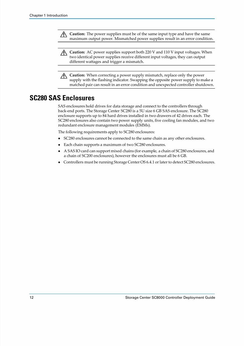
SC280 SAS EnclosuresSAS enclosures hold drives for data storage and connect to the controllers through
back‐end ports. The Storage Center SC280 is a 5U size 6 GB SAS enclosure. The SC280
enclosure supports up to 84 hard drives installed in two drawers of 42 drives each. The
SC280 enclosures
also
contain
two
power
supply
units,
five
cooling
fan
modules,
and
two
redundant enclosure management modules (EMMs).
The following requirements apply to SC280 enclosures:
SC280 enclosures cannot be connected to the same chain as any other enclosures.
Each chain supports a maximum of two SC280 enclosures.
A SAS IO card can support mixed chains (for example, a chain of SC280 enclosures, and
a chain of SC200 enclosures), however the enclosures must all be 6 GB.
Controllers must be running Storage Center OS 6.4.1 or later to detect SC280 enclosures.
Caution: The power supplies must be of the same input type and have the same
maximum output power. Mismatched power supplies result in an error condition.
Caution: AC power supplies support both 220 V and 110 V input voltages. When
two identical power supplies receive different input voltages, they can output
different wattages and trigger a mismatch.
Caution: When correcting a power supply mismatch, replace only the power supply with the flashing indicator. Swapping the opposite power supply to make a
matched pair can result in an error condition and unexpected controller shutdown.

8/18/2019 Deployment Guide Sc8000
http://slidepdf.com/reader/full/deployment-guide-sc8000 23/218
SC280 SAS Enclosures
Dell Compellent 13
SC280 Enclosure Front Panel Features and IndicatorsThe overall enclosure status is shown on a panel located on the left side of the enclosure.
Figure 9. SC280 Enclosure Front Panel Features and Indicators
Item Feature/Indicator Icon Description
1 Unit ID display A numerical display of the enclosure unit identification number. This number is set by Storage
Center.
2 Input switch Not currently used (though it can be used to set the
Unit ID Display, the ID is automatically reset by the
Storage Center).
3 System power indicator • Amber: Enclosure is in standby (not operational).
• Green: Enclosure is on (operational).
4 Module fault Amber: Hardware fault (PCM fault, Fan fault, SSB
module fault. Check indicators on individual modules).
5 Logical status indicator Amber: change of status or fault from something other than the enclosure itself (this may be from an internal or external RAID controller or HBA, but is usually
associated with a disk drive as indicated by its own
fault LED).
6 Drawer Fault
1
Amber:
drive,
cable,
or
sideplane
fault
has
occurred
in
drawer 1.
7 Drawer Fault 2 Amber: drive, cable, or sideplane fault has occurred in
drawer 2.
4
3
5
2
1
6
7

8/18/2019 Deployment Guide Sc8000
http://slidepdf.com/reader/full/deployment-guide-sc8000 24/218
Chapter 1 Introduction
14 Storage Center SC8000 Controller Deployment Guide
SC280 Drawer Front-Panel Features and IndicatorsEach side of each drawer shows status using LED indicators.
Figure 10. SC280 Drawer Front Panel Features and Indicators
Item Feature/Indicator Icon Description
1 Sideplane OK/Power • Off:
Sideplane
card
or
cable
fault.
• Green: Sideplane card and cable are functional.
2 Drawer Fault Amber: Sideplane card fault or drive failure causing
loss of availability or redundancy.
3 Logical fault indicator • Amber: Host indicated drive fault.
• Flashing Amber: Array(s) in impacted state.
4 Cable Fault Amber: Cable fault.
5 Activity Bar Graph Six variable‐intensity LEDs dynamically display drive
access in the enclosure drawer.
4
3
5
2
1

8/18/2019 Deployment Guide Sc8000
http://slidepdf.com/reader/full/deployment-guide-sc8000 25/218
SC280 SAS Enclosures
Dell Compellent 15
SC280 Back-Panel Features and IndicatorsThe enclosure back panel provides controls to power up and reset the enclosure, indicators to show the enclosure status, and connections for back‐end cabling.
Figure 11. SC280 Back Panel Identification
Item Name
1 Optional cable retention positions (4).
2 IO enclosure management modules (2). See SC280 EMM Features and Indicators on
page 16.
3 Fan modules (5).
4 Power supply units (2). See SC280 Power Supply Unit Features and Indicators on page 17.
5 Power switches (2).
6 Optional cable retention positions (2).
2
1
4
3
5
6

8/18/2019 Deployment Guide Sc8000
http://slidepdf.com/reader/full/deployment-guide-sc8000 26/218
Chapter 1 Introduction
16 Storage Center SC8000 Controller Deployment Guide
SC280 EMM Features and IndicatorsSC280 enclosures include two Enclosure Management Modules (EMM) in two interface
slots. Each EMM IO Module includes an EEPROM that holds data describing the function
and capability of the EMM module. Each EMM module can discover the type and
capabilities of its partner EMM module within the enclosure. Incompatible configurations result in an enclosure system alarm.
Each port has four separately arbitrated physical lanes. A green LED indicates the status of each lane. The IO Module and Fault indicators provide status as described below.
Figure 12. IO Module Indicators
Item Name Icon Description
1 Power indicator • Green (steady): Module OK.
• Green (flashing): Vital product data (VPD) fault.
• Off: Module fault.
2 IO Module fault indicator
Amber: IO module error.
3 Console — Factory use only.
4 Lane LEDs — • Solid Green: Connected, No activity.
• Flashing: Activity.
5 SAS port A (in) Connects to other enclosures.
6 SAS port B (out) Connects to other enclosures.
7 SAS Port C The C‐port always connects to the controller.
2
1 43
5 6 7

8/18/2019 Deployment Guide Sc8000
http://slidepdf.com/reader/full/deployment-guide-sc8000 27/218
SC280 SAS Enclosures
Dell Compellent 17
SC280 Power Supply Unit Features and IndicatorsSC280 enclosures include two Power Supply Units (PSUs) in two interface slots.
Figure 13. SC280 PSU Features and Indicators
Separate and unique conditions are indicated if all three LEDs are in the same state:
If all three LEDs are off, then there is no AC power to either PSU.
If all three LEDs are on, then the General Enclosure Management (GEM) software has
lost communication with the PSU.
Item Name Icon Description
1 Release latch —
2 PSU fault indicator • Amber (steady) — PSU fault, PSU not supplying
power
• Amber (flashing) — PSU firmware is downloading
3 AC power indicator • Amber (steady) — AC power is not detected
• Amber (flashing) — PSU firmware is downloading
4 Power OK indicator • Green (steady) — This PSU is providing power
• Green (flashing) — AC power is present, but this PSU is in standby mode (the other PSU is providing
power)
5 Power switch — Controls power for the enclosure.
43 521

8/18/2019 Deployment Guide Sc8000
http://slidepdf.com/reader/full/deployment-guide-sc8000 28/218
Chapter 1 Introduction
18 Storage Center SC8000 Controller Deployment Guide
Fan Module Features and IndicatorsSC280 enclosures include five fan modules in five interface slots.
Figure 14. SC280 Fan Module Features and Indicators
Item Control/Feature Icon Description
1 Release latch
2 Module OK Green — Module OK
3 Battery fault Not currently used
4 Fan fault Amber — Loss of communication with the fan module, or reported fan speed is out of tolerance
1
2
3
4

8/18/2019 Deployment Guide Sc8000
http://slidepdf.com/reader/full/deployment-guide-sc8000 29/218
SC280 SAS Enclosures
Dell Compellent 19
SC280 Enterprise Plus DrivesEnterprise Plus Drives can only be installed in SC280 enclosures. An indicator gives status and activity information as described below.
Figure 15. SC280 Hard Drive Indicators
Item Name Indicator Code
1 Hard drive activity indicator • Steady Amber — Drive fault
• Flashing Amber (on 1 sec / off 1 sec) — Drive or enclosure
indicator is set to On in System Manager. (With the drive
indicator, the containing drawer fault LED also flashes; with the enclosure indicator, all drives’ and both drawers’ fault LEDs flash.)
1

8/18/2019 Deployment Guide Sc8000
http://slidepdf.com/reader/full/deployment-guide-sc8000 30/218
Chapter 1 Introduction
20 Storage Center SC8000 Controller Deployment Guide
SC280 Drive NumberingSC280 drives are located in two drawers, each containing three rows of drives. The drives
are numbered 1–42 in drawer 1, from front to back and left to right, and 43–84 in drawer 2.
Figure 16. Hard Drive Numbering
SC200/220 SAS EnclosuresSAS enclosures hold drives for data storage and connect to the controllers through
back‐end ports. The Storage Center SC200 and SC220 are 2U size SAS enclosures. The
SC200 enclosure supports up to 12 3.5‐inch hard drives installed in a four‐column, three‐
row configuration. The SC220 enclosure supports up to 24 2.5‐inch hard drives installed
vertically side‐ by‐side. The SC200 and SC220 enclosures ship with two power supply/cooling fan modules and two redundant enclosure management modules (EMMs).
The following requirements apply to SC200 and SC220 enclosures:
SC200 and SC220 enclosures cannot be connected to the same chain as any other enclosures.
Controllers must be running Storage Center OS 6.2 or later to detect SC200 and SC220
enclosures.

8/18/2019 Deployment Guide Sc8000
http://slidepdf.com/reader/full/deployment-guide-sc8000 31/218
SC200/220 SAS Enclosures
Dell Compellent 21
SC200/220 Front-Panel Features and IndicatorsThe front panel shows the enclosure and power status.
Figure 17. SC200 Front Panel Features and Indicators
Figure 18. SC220 Front Panel Features and Indicators
Item Name Icon Description
1 Enclosure status indicator
Lights when the enclosure power is on.
• Off: No power.
• On steady blue: Normal operation.
• Flashing blue: Indicates that Storage Center is identifying
the enclosure.
• On steady amber: Enclosure is turning on or was reset.
• Flashing amber: Enclosure is in the fault state.
2 Power status
indicator
Lights when at least one power supply is supplying power to
the enclosure.
• Off: Both power supplies are off.
• On steady green: At least one power supply is providing
power to the enclosure.
3 Hard drives — • SC200: Up to 12 3.5‐inch hard drives.
• SC220: Up to 24 2.5‐inch hard drives.
2
1
3
2
1
3

8/18/2019 Deployment Guide Sc8000
http://slidepdf.com/reader/full/deployment-guide-sc8000 32/218
Chapter 1 Introduction
22 Storage Center SC8000 Controller Deployment Guide
SC200/220 Back-Panel Features and IndicatorsThe enclosure back panel provides controls to power up and reset the enclosure, indicators to show the enclosure status, and connections for back‐end cabling.
Figure 19. SC200/SC220 Back Panel Features and Indicators
Item Name Icon Description
1 DC power indicator • Green: Normal operation. The power supply
module is supplying DC power to the enclosure.
• Off: Power switch is off, the power supply is not connected to AC power, or there is a fault condition
2 Power supply/cooling
fan indicator• Amber: Power supply/cooling fan fault is detected
• Off: Normal operation
3 AC power
indicator • Green:
Power
supply
module
is
connected
to
a
source of AC power, whether the power switch is on
• Off: Power supply module is disconnected from a
source of AC power
4 Power switches (2) — Controls power for the enclosure. There is one switch
for each power supply/cooling fan module.
5 Power supply/cooling
fan modules (2)— Contains a 700 W power supply and fans that provide
cooling for the enclosure
6 Enclosure Management Modules (2)
— EMMs provide the data path and enclosure
management functions for the enclosure
! !
Compellent SC2
Compellent SC2
4
2
1
5 6
3

8/18/2019 Deployment Guide Sc8000
http://slidepdf.com/reader/full/deployment-guide-sc8000 33/218
SC200/220 SAS Enclosures
Dell Compellent 23
SC200/220 EMM Features and IndicatorsSC200 and SC220 enclosures include two Enclosure Management Module (EMM) IO
modules in two interface slots.
Figure 20. SC200/SC220 EMM Features and Indicators
Item Name Icon Description
1 System status indicator Not used on SC200/220 enclosures
2 Debug port For
engineering
use
only
3 SAS port A (in) Connects to the controller or to other enclosures. SAS ports A and B can be used for either input or output, however for cabling consistency, use port A as an input port.
4 Port A link status • Green: All the links to the port are connected
• Amber: One or more links are not connected
• Off: Enclosure is not connected
5 SAS port B (out) Connects to the controller or to other enclosures. SAS ports A and B can be used for either input or output, however for cabling consistency, use port B as an output port.
6 Port B link status • Green: All the links to the port are connected
• Amber: One or more links are not connected
• Off: Enclosure is not connected
7 EMM status indicator • Steady Green: Normal operation
• Amber: Enclosure did not boot or is not properly
configured
• Flashing Green: Automatic update in process
• Flashing Amber Twice: Enclosure is unable to
communicate with other enclosures
• Flashing Amber Four Times: Firmware update failed
• Flashing Amber Five Times: Firmware versions are
different between the two EMMs
Compellent SC2
1 2 73 4 5 6

8/18/2019 Deployment Guide Sc8000
http://slidepdf.com/reader/full/deployment-guide-sc8000 34/218
Chapter 1 Introduction
24 Storage Center SC8000 Controller Deployment Guide
SC200/220 Enterprise Plus DrivesEnterprise Plus Drives can only be installed in SC200/220 enclosures. Drives are installed
either vertically (SC220) or horizontally (SC200) in the enclosure. Indicators give status and
activity information as described below.
Figure 21. SC200 Hard Drive Indicators
Figure 22. SC220 Hard Drive Indicators
Item Name Indicator Code
1 Hard drive activity indicator • Flashing green: Indicates drive activity
• Steady green: Indicates no drive activity
2 Hard drive status indicator • Steady green: Normal operation
• Flashing green (on 1sec/ off 1 sec): Drive or enclosure
indicator is set to On in System Manager. (With the
enclosure indicator, all drives’ fault LEDs flash.)
• Off: No power to the drive
1
2
1 2

8/18/2019 Deployment Guide Sc8000
http://slidepdf.com/reader/full/deployment-guide-sc8000 35/218
SC200/220 SAS Enclosures
Dell Compellent 25
SC200/220 Drive NumberingIn SC200 and SC220 enclosures, drives are numbered from left to right starting from 0. Storage Center identifies drives as Disk-XX ‐YY , where XX is the number of the enclosure
that physically contains the drive, and YY is the drive position inside the enclosure.
SC200: Drives are numbered in rows starting from 0 at the top‐left drive.
Figure 23. SC200 Enclosure Drive Numbering
SC220: Drives are numbered starting from 0 at the left‐most drive.
Figure 24. SC220 Enclosure Drive Numbering
Drive 1
Drive 5
Drive 9
Drive 2
Drive 6
Drive 10
Drive 3
Drive 7
Drive 11
Drive 4
Drive 8
Drive 0
0 1 32 4 6 10 115 7 8 9 12 13 14 16 17 18 19 20 21 22 2315
8/18/2019 Deployment Guide Sc8000
http://slidepdf.com/reader/full/deployment-guide-sc8000 36/218
Chapter 1 Introduction
26 Storage Center SC8000 Controller Deployment Guide
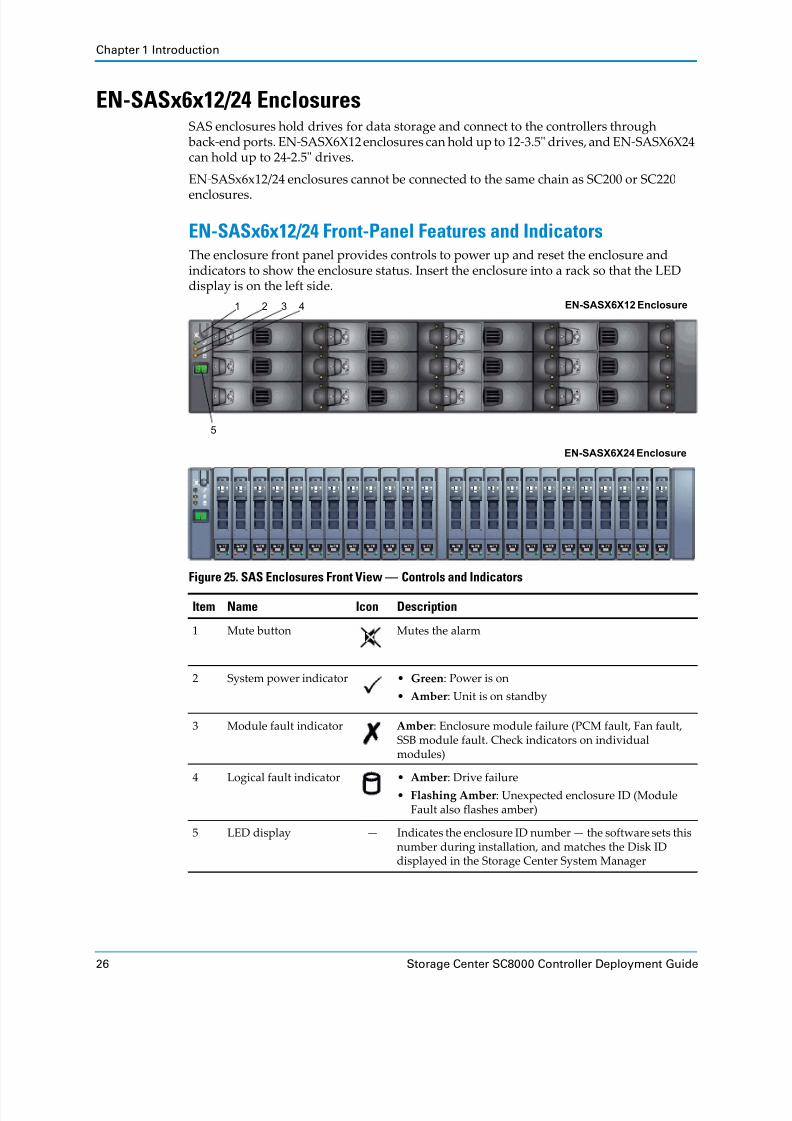
EN-SASx6x12/24 EnclosuresSAS enclosures hold drives for data storage and connect to the controllers through
back‐end ports. EN‐SASX6X12 enclosures can hold up to 12‐3.5ʺ drives, and EN‐SASX6X24
can hold up to 24‐2.5ʺ drives.
EN‐SASx6x12/24 enclosures cannot be connected to the same chain as SC200 or SC220
enclosures.
EN-SASx6x12/24 Front-Panel Features and IndicatorsThe enclosure front panel provides controls to power up and reset the enclosure and
indicators to show the enclosure status. Insert the enclosure into a rack so that the LED
display is on the left side.
Figure 25. SAS Enclosures Front View — Controls and Indicators
Item Name Icon Description
1 Mute button Mutes the alarm
2 System power indicator • Green: Power is on
• Amber: Unit is on standby
3 Module fault indicator Amber: Enclosure module failure (PCM fault, Fan fault, SSB module fault. Check indicators on individual modules)
4 Logical fault indicator • Amber: Drive failure
• Flashing Amber: Unexpected enclosure ID (Module
Fault also flashes amber)
5 LED display — Indicates the enclosure ID number — the software sets this number during installation, and matches the Disk ID
displayed in the Storage Center System Manager
1 3 4
5
2 EN-SASX6X12 Enclosure
EN-SASX6X24 Enclosure

8/18/2019 Deployment Guide Sc8000
http://slidepdf.com/reader/full/deployment-guide-sc8000 37/218
EN-SASx6x12/24 Enclosures
Dell Compellent 27
EN-SASx6x12/24 Back-Panel Features and IndicatorsThe enclosure back panel provides controls to power up and reset the enclosure, indicators to show the enclosure status, and connections for back‐end cabling.
Figure 26. SAS Enclosure Rear View — Controls and Indicators
Item Name Icon Description
1 AC power indicator • Green: Normal operation
• Amber: No AC power
2 Fan indicator • Green: Normal operation
• Amber: Fan failure
3 PCM status indicator • Green: Normal operation
• Amber: Power supply failure
4 DC power indicator • Green: Normal operation
• Amber: No DC power
5 Power switch — Controls power for the enclosure
6 Power Cooling Module (PCM) — one of two
— Contains fans that provide cooling for the enclosure
7 Storage Bridge Bay (SBB) — one of two — See EN‐SASx6x12/24 SBB Module Features and Indicators on page 28
1
2
3
4
5 6 7

8/18/2019 Deployment Guide Sc8000
http://slidepdf.com/reader/full/deployment-guide-sc8000 38/218
Chapter 1 Introduction
28 Storage Center SC8000 Controller Deployment Guide
EN-SASx6x12/24 SBB Module Features and IndicatorsSAS enclosures include two Storage Bridge Bay (SBB) IO modules in two SBB‐compliant interface slots. Each SBB IO Module includes an EEPROM that holds data describing the
function and capability of the SBB module. Each SBB module can discover the type and
capabilities of its partner SBB module within the enclosure. Incompatible configurations result in an enclosure system alarm.
Each port has four separately arbitrated physical lanes. A green LED indicates the status of each lane. The IO Module and Fault indicators provide status as described below.
Figure 27. IO Module Indicators
Item Name Icon Description
1 IO Module indicator On Steady: Normal operation
2 IO Module fault indicator
On: IO module error
3 SAS port A (in) Connects to other enclosures
4 Lane LEDs — • Solid Green: Connected, No activity
• Flashing: Activity
5 SAS port B (out) Connects to other enclosures
6 SAS Port C The C‐port always connects to the controller.
1
2
4 63 5

8/18/2019 Deployment Guide Sc8000
http://slidepdf.com/reader/full/deployment-guide-sc8000 39/218
EN-SASx6x12/24 Enclosures
Dell Compellent 29
EN-SASx6x12/24 Standard SAS DrivesStandard SAS drives can only be installed in EN‐SASx6x12/24 enclosures. Drives are
installed either vertically or horizontally in the enclosure. Indicators give status and
activity information as described below.
Figure 28. EN-SASx6x12 Standard SAS Drive Indicators
Figure 29. EN-SASx6x24 Standard SAS Drive Indicators
Item Name Description
1 Amber LED • Off: No drive, or drive is operating
• On: Drive fault
• Flashing (on 1 sec/off 1 sec): Drive or enclosure
indicator is set to On in System Manager.
2 Green LED • Green: Connected, No activity
• Flashing: Activity
3 Anti‐tamper Indicator (when
present)• Red: Locked
• Black: Unlocked
4 Lock (when present) Insert key or T10 Torx driver and turn to lock/unlock
1
2
3 4
1 2

8/18/2019 Deployment Guide Sc8000
http://slidepdf.com/reader/full/deployment-guide-sc8000 40/218
Chapter 1 Introduction
30 Storage Center SC8000 Controller Deployment Guide
EN-SASx6x12/24 Drive NumberingIn EN‐SASX6X12 and EN‐SASX6X24 enclosures, drives are numbered from left to right starting from 1. Storage Center identifies drives as Disk-XX ‐YY , where XX is the number of the enclosure that physically contains the drive, and YY is the drive position inside the
enclosure.
EN‐
SASX6X12:
Drives
are
numbered
in
rows
starting
from
1
at
the
top‐
left
drive.
Figure 30. EN-SASx6x12 Enclosure Drive Numbering
EN‐SASX6X24: Drives are numbered starting from 1 at the left‐most drive.
Figure 31. EN-SASx6x24 Enclosure Drive Numbering
Drive 1
Drive 5
Drive 9
Drive 2
Drive 6
Drive 10
Drive 3
Drive 7
Drive 11
Drive 4
Drive 8
Drive 12
241 32 4 6 10 115 7 8 9 12 13 14 16 17 18 19 20 21 22 2315

8/18/2019 Deployment Guide Sc8000
http://slidepdf.com/reader/full/deployment-guide-sc8000 41/218
Dell Compellent 31
2 Install the Hardware
Verify that the ordered equipment arrived safely, install IO cards in the controller(s), disks in the enclosures (as required) and mount the equipment in a rack.
ContentsPrepare for Installation . . . . . . . . . . . . . . . . . . . . . . . . . . . . . . . . . . . . . . . . . . . . . . . . . . . . . . . 31
Safety Precautions . . . . . . . . . . . . . . . . . . . . . . . . . . . . . . . . . . . . . . . . . . . . . . . . . . . . . . . . . . . 32
Install IO Cards the Controller(s) . . . . . . . . . . . . . . . . . . . . . . . . . . . . . . . . . . . . . . . . . . . . . . 35
Label the Controllers . . . . . . . . . . . . . . . . . . . . . . . . . . . . . . . . . . . . . . . . . . . . . . . . . . . . . . . . . 44
Mount the Hardware in a Rack . . . . . . . . . . . . . . . . . . . . . . . . . . . . . . . . . . . . . . . . . . . . . . . . 45
Install Drives in SC280 Enclosures . . . . . . . . . . . . . . . . . . . . . . . . . . . . . . . . . . . . . . . . . . . . . 48
Install Drives in EN‐SASx6x12/24 Enclosures . . . . . . . . . . . . . . . . . . . . . . . . . . . . . . . . . . . . 50
Install Enterprise Plus Drives in SC200/220 Enclosures . . . . . . . . . . . . . . . . . . . . . . . . . . . 53
Prepare for InstallationBefore you begin, make sure that the correct equipment is available, the installation
environment is
ready,
and
you
have
the
necessary
materials.
Unpack and Inventory the Storage Center EquipmentMake sure the equipment that was ordered arrived safely on site:
Controllers
Enclosures and drives
IO cards
Front‐end cables
Back‐end cables
Switches
Prepare the Installation EnvironmentMake sure that the environment is ready for installation.
Rack Space: There must be sufficient space in the rack to accommodate the Storage
Center controller(s), enclosures, and switches.
Power: Power must be available in the rack, and the power delivery system must meet the power requirements for the Storage Center.

8/18/2019 Deployment Guide Sc8000
http://slidepdf.com/reader/full/deployment-guide-sc8000 42/218
Chapter 2 Install the Hardware
32 Storage Center SC8000 Controller Deployment Guide
Connectivity: The rack must be wired for connectivity to the management network and
any networks that carry front‐end IO from the Storage Center to servers.
Gather Required MaterialsMake sure that you have the following items before you begin the installation.
Safety PrecautionsTo avoid injury and damage to the equipment, always follow these safety precautions.
If equipment described in the document is used in a manner not specified by Dell Compellent, the protection provided by the equipment may be impaired. For your safety
and protection, observe the following rules:
Electrical Safety PrecautionsAlways follow electrical safety precautions to avoid injury and damage to the equipment.
Provide a suitable power source with electrical overload protection. All components in the Storage Center must be grounded before applying power. Make sure that there is a
safe electrical earth connection to power supply cords. Check the grounding before
applying power.
The plugs on the power supply cords are used as the main disconnect device. Make sure
that the socket outlets are located near the equipment and are easily accessible.
Know the locations of the equipment power switches and the roomʹs emergency power‐off switch, disconnection switch, or electrical outlet.
Required Item Description
Storage Center license file Makes settings available depending on what features were
purchased.
RS‐232 serial cable and PC or laptop
Used to run commands and view console messages during
controller configuration.
Computer connected to the
same network as the Storage
Center
Used to connect to the Storage Center System Manager (through a
web browser) to complete the Storage Center configuration.
Hardware Serial Number (HSN) and System Serial Number (SSN)
Used to configure the controller(s).
Storage Architect or Business Partner supplied pre‐
installation document(s)
(Optional) Provide site‐specific settings used during deployment:
• List of hardware needed to support storage requirements
• Optional connectivity diagrams to illustrate cabling between the
controllers, enclosures, switches, and servers
• Optional network information, such as IP addresses, subnet masks, gateways
Storage Center Maintenance
CD(Optional) Used to update the Storage Center OS when internet access is not available.
Note: See the safety and regulatory information that shipped with each Storage
Center component. Warranty information may be included within this document or as a separate document.

8/18/2019 Deployment Guide Sc8000
http://slidepdf.com/reader/full/deployment-guide-sc8000 43/218
Safety Precautions
Dell Compellent 33
Do not work alone when working with high‐voltage components.
Do not use mats designed to decrease electrostatic discharge as protection from
electrical shock. Instead, use rubber mats that have been specifically designed as
electrical insulators.
Do not remove covers from the Power Control Module (PCM). Disconnect the power connection before removing a PCM from the enclosure.
Do not remove a faulty PCM unless you have a replacement model of the correct type
ready for insertion. A faulty PCM must be replaced with a fully operational module
within 24 hours.
Permanently unplug the enclosure before you move it or if you think it has become
damaged in any way. When powered by multiple AC sources, disconnect all supply
power for complete isolation.
General Safety PrecautionsTo avoid injury and damage to the equipment, always follow general safety precautions.
Keep the area around the chassis clean and free of clutter.
Place the chassis cover and any system components that have been removed away from
the controller or on a table so that they are not in the way of foot traffic.
While working on the controller, do not wear loose clothing such as neckties and
unbuttoned shirt sleeves, which can come into contact with electrical circuits or be
pulled into a cooling fan.
Remove any jewelry or metal objects from your body because they are excellent metal conductors that can create short circuits and harm you if they come into contact with
printed circuit
boards
or
areas
where
power
is
present.
Do not lift an enclosure by the handles of the Power Cooling Modules (PCMs). They are
not designed to hold the weight of the entire enclosure, and the enclosure cover may
become bent.
Before moving an enclosure, remove the PCMs to minimize weight.
In order to comply with applicable safety, emission, and thermal requirements, do not remove bay covers from enclosures. Make sure that all bays are populated with plug‐in
modules.
Do not remove bay covers or drives until ready to replace them.
Warning: Disconnect power from the controller when removing or installing
components that are not hot‐swappable. When disconnecting power, first power down the controller using the Storage Center System Manager and then unplug the
power cords from all the power supply modules in the controller.
Warning: To avoid injury, do not attempt to the lift a controller or enclosure by
yourself. Always get assistance when lifting the controller.
Caution: Do not operate the controller without the cover, except when replacing
cooling fans.
Warning: The memory modules may be hot for several minutes after the controller has been powered down. Wait for the memory modules to cool before handling
them.

8/18/2019 Deployment Guide Sc8000
http://slidepdf.com/reader/full/deployment-guide-sc8000 44/218
Chapter 2 Install the Hardware
34 Storage Center SC8000 Controller Deployment Guide
Electrostatic Discharge PrecautionsTo avoid injury and damage to the equipment, always follow electrostatic discharge (ESD) precautions t
Electrostatic discharge (ESD) is generated by two objects with different electrical charges coming into contact with each other. The resulting electrical discharge can damage
electronic components and printed circuit boards. Follow these guidelines to protect your equipment from ESD:
It is recommended that you always use a static mat and static strap while working on
components in the interior of the controller.
Observe all
conventional
ESD
precautions
when
handling
plug
‐in
modules
and
components.
Use a suitable ESD wrist or ankle strap.
Avoid contact with backplane components and module connectors.
Keep all components and printed circuit boards (PCBs) in their antistatic bags until ready for use.
Caution: To ensure proper controller cooling, memory module blanks must be
installed in any memory socket that is not occupied.
Warning: To prevent eye damage, do not stare into the laser beam aperture of an
SFP+ transceiver.

8/18/2019 Deployment Guide Sc8000
http://slidepdf.com/reader/full/deployment-guide-sc8000 45/218
Install IO Cards the Controller(s)
Dell Compellent 35
Install IO Cards the Controller(s)Before you mount the controller(s) in a rack, install the IO cards.
Open the CoverOpen the cover to gain access to the inside of the controller.
1 Rotate the latch release lock counter clockwise to the unlocked position.
2 Lift the latch on top of the controller and slide the cover back.
3 Grasp the cover on both sides, and carefully lift the cover away from the controller.
Figure 32. Opening the Cover
Caution: Do not operate the controller without the cover, except when replacing
cooling fans.
Caution: Do not slide the controller into a rack with the cover open. Riser 2
contains a chassis intrusion detection switch that can be easily damaged when
sliding a controller into the rack with the cover open.
1 Controller cover
2 Latch
3 Latch release lock
1
23

8/18/2019 Deployment Guide Sc8000
http://slidepdf.com/reader/full/deployment-guide-sc8000 46/218
Chapter 2 Install the Hardware
36 Storage Center SC8000 Controller Deployment Guide
Remove the Cooling Shroud
Remove the cooling shroud to gain access to the memory sockets.
1 Hold onto the two touch points of the cooling shroud.
2 Lift the cooling shroud away from the controller.
Figure 33. Removing and Inserting the Cooling Shroud
Insert the Cooling Shroud
Use this procedure to install the cooling shroud.
1 Align the tabs on the cooling shroud with the securing slots on the chassis.
2 Lower the cooling shroud into the chassis until it is firmly seated.
1 Cooling shroud
2 Touch points
Note: For proper seating of the cooling shroud in the chassis, ensure that the
cables inside the controller are routed along the chassis wall and secured using
the cable securing bracket.
1
2

8/18/2019 Deployment Guide Sc8000
http://slidepdf.com/reader/full/deployment-guide-sc8000 47/218
Install IO Cards the Controller(s)
Dell Compellent 37
Install IO CardsInstall the IO cards in the controller(s) based on the IO card priority rules. For dual‐controller systems, install IO cards in the same locations in both controllers.
Determine Where IO Cards Should Be Installed
The following
table
provides
guidelines
for
installing
IO
cards
to
ensure
proper
cooling
and mechanical fit. Install IO cards using the card priority and slot priority order indicated.
Populate the slots as follows:
Install low‐profile IO cards in slots 3 through 1. After filling these slots, low‐profile
cards may be installed in slots 4, 5, and 6 when used with the adaptive bracket.
Install full‐height IO cards beginning in slot 6, followed by slot 5, then slot 4 if needed.
Slot 7 is reserved for the Cache Card.
Note: Low‐profile IO cards are shipped with an adaptive full‐height bracket that must be installed to use the IO card in a slot designed for a full‐height IO card. When
a low‐profile card is installed in a full‐height slot the ports are reversed, so port number 1 is on the right.
Note: To use Multi‐VLAN Tagging (MVLAN) install a Chelsio 10 Gb iSCSI card. MVLAN is managed in Enterprise Manager.
Type Card HeightSpeed(Gb)
Numberof Ports
CardPriority
SlotPriority
iSCSI Chelsio S320E‐LP‐CR
(SFP+ transceiver required for optical support)
Low‐profile 10 2 11 3, 2, 1, 4, 5
iSCSI Chelsio S320E‐CR* (SFP+ transceiver required for optical support)
Full‐height 10 2 10 4, 5, 6
iSCSI QLogic QLE4062 Low‐profile 1 2 7 3, 2, 1, 4, 5
SAS LSI SAS9201‐16E Full‐height 6 4 2 6, 5, 4
SAS LSI SAS9206‐16E Low profile 6 4 2 3, 2, 1, 6, 5, 4
Fibre Channel Emulex LPe12004‐M8* Full‐height 8 4 9 4, 5, 6
Fibre Channel Emulex LPe12002‐M8* Low‐profile 8 2 5 3, 2, 1, 4, 5
Fibre Channel QLogic QLE2662 Low‐profile 16 2 3 3, 2, 1, 4, 5,
6
Fibre Channel QLogic QLE2562 Low‐profile 8 2 4 3, 2, 1, 4, 5, 6
Fibre Channel QLogic QLE2564 Full‐height 8 4 8 4, 5, 6
FCoE Qlogic QLE8152 (SFP+
transceiver required for optical support)
Low‐profile 10 2 6 3, 2, 1, 4, 5
Cache card Dell Full‐height n/a n/a 1 7

8/18/2019 Deployment Guide Sc8000
http://slidepdf.com/reader/full/deployment-guide-sc8000 48/218
Chapter 2 Install the Hardware
38 Storage Center SC8000 Controller Deployment Guide
* These IO cards cannot be ordered for SC8000 controllers. An SC8000 controller can contain these IO cards only if they weretransferred to the SC8000 controller during an upgrade from a CT‐SC030 or CT‐SC040 controller.
See Also
SC8000 Back‐Panel Features and Indicators on page 10
Install Low-Profile IO Cards in Slots 1–3
To install low‐profile IO cards, first remove riser 1.
1 Remove riser 1.
a Hold onto the touch points of the riser.
b Lift the riser from the riser connector on the system board.
Table 1. Removing Riser 1
1 Riser 1 cage 4 Riser guide, back (left)
2 Riser 1 5 Riser 1 connector
3 Riser guide, back (right) 6 Riser guide, front
1
2
3
456
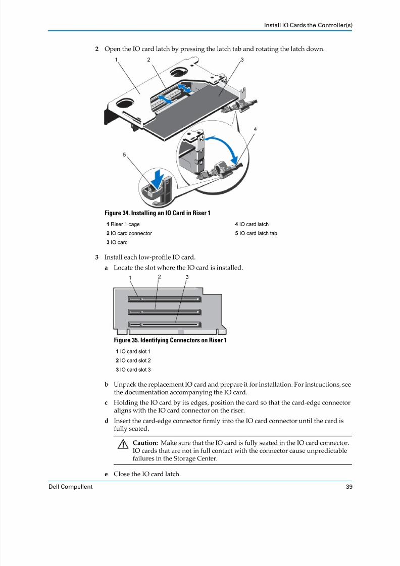
8/18/2019 Deployment Guide Sc8000
http://slidepdf.com/reader/full/deployment-guide-sc8000 49/218
Install IO Cards the Controller(s)
Dell Compellent 39
2 Open the IO card latch by pressing the latch tab and rotating the latch down.
Figure 34. Installing an IO Card in Riser 1
3 Install each low‐profile IO card.
a Locate the slot where the IO card is installed.
Figure 35. Identifying Connectors on Riser 1
b Unpack the replacement IO card and prepare it for installation. For instructions, see
the documentation accompanying the IO card.
c Holding the IO card by its edges, position the card so that the card‐edge connector aligns with the IO card connector on the riser.
d Insert the card‐edge connector firmly into the IO card connector until the card is
fully seated.
e Close the IO card latch.
1 Riser 1 cage 4 IO card latch
2 IO card connector 5 IO card latch tab
3 IO card
1 IO card slot 1
2 IO card slot 2
3 IO card slot 3
Caution: Make sure that the IO card is fully seated in the IO card connector. IO cards that are not in full contact with the connector cause unpredictable
failures in the Storage Center.
1 2 3
4
5
1 2 3

8/18/2019 Deployment Guide Sc8000
http://slidepdf.com/reader/full/deployment-guide-sc8000 50/218
Chapter 2 Install the Hardware
40 Storage Center SC8000 Controller Deployment Guide
4 Insert riser 1.
a Align the riser with the connector and the riser guides.
b Lower the riser into place until the riser is fully seated in the connector.
Table 2. Removing Riser 1
1 Riser 1 cage 4 Riser guide, back (left)
2 Riser 1 5 Riser 1 connector
3 Riser guide, back (right) 6 Riser guide, front
1
2
3
456
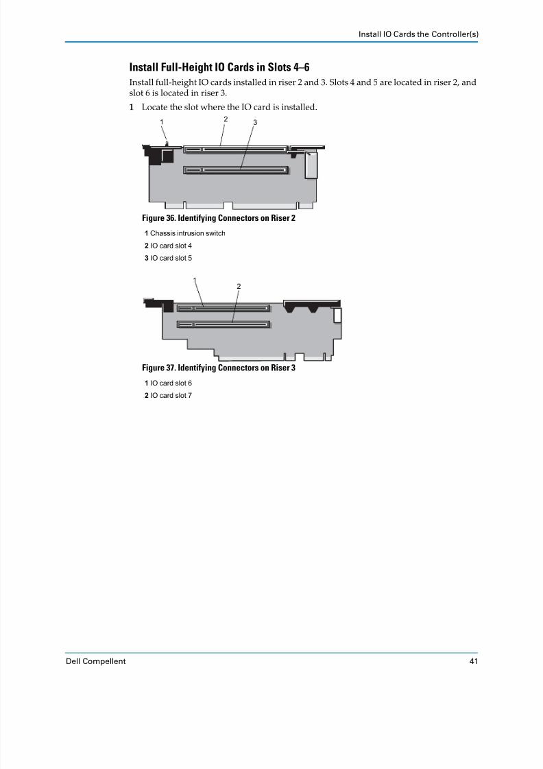
8/18/2019 Deployment Guide Sc8000
http://slidepdf.com/reader/full/deployment-guide-sc8000 51/218
Install IO Cards the Controller(s)
Dell Compellent 41
Install Full-Height IO Cards in Slots 4–6
Install full‐height IO cards installed in riser 2 and 3. Slots 4 and 5 are located in riser 2, and
slot 6 is located in riser 3.
1 Locate the slot where the IO card is installed.
Figure 36. Identifying Connectors on Riser 2
Figure 37. Identifying Connectors on Riser 3
1 Chassis intrusion switch
2 IO card slot 4
3 IO card slot 5
1 IO card slot 6
2 IO card slot 7
1 32
12

8/18/2019 Deployment Guide Sc8000
http://slidepdf.com/reader/full/deployment-guide-sc8000 52/218
Chapter 2 Install the Hardware
42 Storage Center SC8000 Controller Deployment Guide
2 Lift the IO card latch out of the slot.
Figure 38. Replacing the IO Card in Riser 2 or 3
3 Unpack
the
replacement
IO
card
and
prepare
it
for
installation.
For
instructions,
see
the
documentation accompanying the IO card.
4 Hold the IO card by its edges and position the card so that the card‐edge connector aligns with the IO card connector on the riser.
5 Insert the card‐edge connector firmly into the IO card connector until the card is fully
seated. Use the supports provided on the cooling shroud.
1 IO card 3 IO card connector
2 IO card latch 4 Riser
Caution: Make sure that the IO card is fully seated in the IO card connector. IO
cards that are not in full contact with the connector cause unpredictable failures in Storage Center.
1
2
3
4

8/18/2019 Deployment Guide Sc8000
http://slidepdf.com/reader/full/deployment-guide-sc8000 53/218
Install IO Cards the Controller(s)
Dell Compellent 43
Figure 39. Seating the IO Card
6 Replace the IO card latch.
7 Press the touch‐point to release the card retention tab (not shown) and rotate the tab
until it locks in place over the IO card.
Close the CoverPerform this procedure to close the cover.
1 Lift the latch on the cover.
2 Place the cover onto the chassis and offset the cover slightly back so that it clears the
chassis hooks and lays flush on the chassis.
3 Push down the latch to move the cover into the closed position.
4 Rotate the latch release lock clockwise to secure the cover.
Figure 40. Closing the Cover
1 Controller cover
2 Latch
3 Latch release lock
1
23

8/18/2019 Deployment Guide Sc8000
http://slidepdf.com/reader/full/deployment-guide-sc8000 54/218
Chapter 2 Install the Hardware
44 Storage Center SC8000 Controller Deployment Guide
Label the ControllersCreate two labels for each controller to facilitate identification in the rack. Apply labels to
the front and back of each controller.
Prerequisites
You must have a label maker, or four blank labels and a writing utensil.
Steps
1 Create two labels for each controller. Each label should contain the controller number and System Serial Number (SSN).
2 Apply two labels to each controller.
a Apply one label to the front of the controller on the top‐left corner.
b Apply one
label
to
the
rear
of
the
controller
on
the
middle
of
the
handle.
Figure 41. SC8000 Controller Labels
Line Label Information Example
1 Controller number CONTR1 or CONTR2
2 System Serial Number 10011
CONTR1
10011

8/18/2019 Deployment Guide Sc8000
http://slidepdf.com/reader/full/deployment-guide-sc8000 55/218
Mount the Hardware in a Rack
Dell Compellent 45
Mount the Hardware in a RackDell Compellent recommends mounting the hardware in a rack to ensure rack safety and
to allow for expansion.
2U and 3U EnclosuresInstall 2U and 3U enclosures in the rack to allow for expansion and so that the rack does not become top‐heavy. This can be accomplished in one of two configurations.
Install the controllers on the bottom of the rack and the enclosures above the controllers.
Install the controllers in the middle of the rack and the enclosures above and below the
controllers.
Steps
1 Mount the controller(s) in a rack. See the instructions included with the rail kit for detailed steps.
2 Mount the enclosure(s) in the rack. See the instructions included with the rail kit for detailed steps.
Figure 42. Recommended Mounting Order — 2U and 3U Enclosures
1 Controllers
2 Enclosures
1
2

8/18/2019 Deployment Guide Sc8000
http://slidepdf.com/reader/full/deployment-guide-sc8000 56/218
Chapter 2 Install the Hardware
46 Storage Center SC8000 Controller Deployment Guide
5U EnclosuresThe 5U enclosures can weigh up to 131 kg (288 lb) and should be installed in the lower portion of the rack to ensure rack stability.
When installed in a rack, the SC280 enclosure extends 36 in. from the front rack posts to the
back of the chassis. Rack modifications may be required to avoid blocking PDUs or to allow
proper strain
relief
for
SAS
cables.
Contact
Dell
Technical
Support
Services
if
site
preparation has not already been done.
Prerequisites
Make sure that the site has the following:
208 V power from an independent source or a rack power distribution unit with a UPS.
(110 V
power
will
not
work.)
A 5U space in the lower 20U of the rack. If the enclosure is to be installed above the 20U
mark (not recommended), a customer‐provided mechanical lift is required.
Power Distribution Unit (PDU) outlets must be type IEC‐320‐C19, with a minimum
output Amperage of 20A per connection.
Steps
Mount the SC280 enclosure into the rack using mounting rails, and optionally secure with
brackets to prevent tipping.
1 Mount the controller(s) in a rack. See the instructions included with the rail kit for detailed steps.
2 Mount the rails in the rack according to instructions included in the rail kit.
3 Mount the enclosure onto the rack rails, using two people to lift the enclosure into
position.
4 Install Hold Down Brackets (HDBs).
a Secure the fixing screws to the rear of the enclosure.
b Secure the HDBs to the rear of the rack.
Warning: A fully configured SC280 enclosure weighs up to 130.7 kg (287.5 lb). An
unpopulated enclosure weighs 62 kg (137 lb). To avoid injury, always lift with two
people, and use lifting straps when required.
If installed above the lower 20U of a rack, a customer‐provided mechanical lift must be used.
Warning: When unpacking the 5U enclosure, two people using lift straps are
required to avoid injury.

8/18/2019 Deployment Guide Sc8000
http://slidepdf.com/reader/full/deployment-guide-sc8000 57/218
Mount the Hardware in a Rack
Dell Compellent 47
Figure 43. Recommended Mounting Order — 5U Enclosures
1 Controllers
2 Enclosures
1
2

8/18/2019 Deployment Guide Sc8000
http://slidepdf.com/reader/full/deployment-guide-sc8000 58/218

8/18/2019 Deployment Guide Sc8000
http://slidepdf.com/reader/full/deployment-guide-sc8000 59/218
Install Drives in SC280 Enclosures
Dell Compellent 49
Figure 44. Inserting an SC280 DDIC
See Also
SC280 Enterprise Plus Drives on page 19
1 DDIC 3 Drive fault LED
2 Release button
2
1
3

8/18/2019 Deployment Guide Sc8000
http://slidepdf.com/reader/full/deployment-guide-sc8000 60/218
Chapter 2 Install the Hardware
50 Storage Center SC8000 Controller Deployment Guide
Install Drives in EN-SASx6x12/24 EnclosuresIf you are installing EN‐SASx6x12 and/or EN‐SASx6x24 enclosures, install drives in the
enclosures.
When installing drives into a 12‐drive enclosure, make sure that all drives in a column are
of the same spindle rate as shown in the following example. Populate the outer columns
first.
Installing 3.5" DrivesInstall 3.5ʺ drive carriers horizontally into the 12‐drive enclosure. If necessary, remove
drive blanks from the enclosures to make room for the drives.
1 Release the drive carrier handle by depressing the latch in the handle.
Figure 45. Release Drive Carrier Handle
2 Insert the Drive Carrier Module into the enclosure.
Figure 46. Installing a Drive Carrier Module
3 Make sure that the drive carrier is oriented so that the drive faces up and the handle
opens from the left.
4 Gently slide the drive carrier all the way into the enclosure.
Column 1 Column 2 Column 3 Column 4
Row 1 7.2K 15K 10K 15K
Row 2 7.2K 15K 10K 15K
Row 3 7.2K 15K 10K 15K

8/18/2019 Deployment Guide Sc8000
http://slidepdf.com/reader/full/deployment-guide-sc8000 61/218

8/18/2019 Deployment Guide Sc8000
http://slidepdf.com/reader/full/deployment-guide-sc8000 62/218
Chapter 2 Install the Hardware
52 Storage Center SC8000 Controller Deployment Guide
Installing 2.5" DrivesInstall 2.5ʺ drive carriers vertically into the 24‐drive enclosure.
1 Make sure that the carrier is oriented so that the drive is on the left side and the handle
opens from the top.
2 Release the carrier handle by pressing the latch in the handle downwards.
3 Insert the carrier into the enclosure in the vertical position.
Figure 49. 2.5" Drive Carrier Module in Open Position
4 Gently slide the carrier all the way into the enclosure until it is stopped by the lever on
the bottom of the carrier.
Figure 50. Inserting a 2.5" Drive Carrier Module (1)
5 Rotate the handle firmly until the handle fully engages. You will hear a click as the latch
engages and holds the handle closed.
See Also
EN‐SASx6x12/24 Standard SAS Drives on page 29
EN‐SASx6x12/24 Drive Numbering on page 30

8/18/2019 Deployment Guide Sc8000
http://slidepdf.com/reader/full/deployment-guide-sc8000 63/218
Install Enterprise Plus Drives in SC200/220 Enclosures
Dell Compellent 53
Install Enterprise Plus Drives in SC200/220 EnclosuresSC200/220 enclosures are shipped with disks installed and/or empty drive blanks in
unused slots. The following instructions show the installation of the Dell Enterprise Plus
drive for reference only.
Figure 51. Installing a Drive
1 Insert the hard drive carrier into the hard drive bay.
2 Slide the drive into the bay until the carrier contacts the backplane.
3 Close the hard drive carrier handle to lock the hard drive in place.
4 Continue
to
push
firmly
until
you
hear
a
click
and
the
handle
fully
engages.5 When the enclosure is turned on and the drives spin up, make sure that the drive LEDs
are on (green), indicating normal conditions.
See Also
SC200/220 Enterprise Plus Drives on page 24
SC200/220 Drive Numbering on page 25
Note: Dell Enterprise Plus drives and Enterprise Solid State Drives (ESSDs) can
only be installed in SC200/220 enclosures.

8/18/2019 Deployment Guide Sc8000
http://slidepdf.com/reader/full/deployment-guide-sc8000 64/218
Chapter 2 Install the Hardware
54 Storage Center SC8000 Controller Deployment Guide

8/18/2019 Deployment Guide Sc8000
http://slidepdf.com/reader/full/deployment-guide-sc8000 65/218
Dell Compellent 55
3 Connect the Back End
Enclosures are connected to controllers using SAS, a point‐to‐point switched topology on
four lanes. Each lane can perform concurrent IO transactions at 6 Gb/sec. Dell Compellent recommends connecting the SAS drive enclosures to the controller(s) using the most redundant options that are available.
Contents
SAS Enclosure
Cabling
Guidelines .
. . . . . . . . . . . . . . . . . . . . . . . . . . . . . . . . . . . . . . . . . . . .
55Connect IPC for Dual‐Controller Storage Centers . . . . . . . . . . . . . . . . . . . . . . . . . . . . . . . . 56
Connect SC200/SC220 Enclosures . . . . . . . . . . . . . . . . . . . . . . . . . . . . . . . . . . . . . . . . . . . . . . 60
Connect SC280 Enclosures . . . . . . . . . . . . . . . . . . . . . . . . . . . . . . . . . . . . . . . . . . . . . . . . . . . . 75
Connect EN‐SASx6x12/24 Enclosures . . . . . . . . . . . . . . . . . . . . . . . . . . . . . . . . . . . . . . . . . . 84
Label the Back‐End Cables . . . . . . . . . . . . . . . . . . . . . . . . . . . . . . . . . . . . . . . . . . . . . . . . . . . . 93
SAS Enclosure Cabling GuidelinesMultiple SAS enclosures are connected to a controller by cabling the enclosures in series. A
series of interconnected enclosures is referred to as a chain. Each chain can contain up to
168 6 Gbps SAS drives.
A SAS chain begins at an initiator port in a controller IO card and connects to the first enclosure. Subsequent enclosures are connected in series. For single‐controller Storage
Centers, the chain ends at the last enclosure. For dual‐controller Storage Centers, the chain
ends in a target port in the opposite controller.
SAS RedundancyRedundant SAS cabling ensures that in the event an IO Card or port fails, IO continues to
flow through the remaining functioning path(s). For dual‐controller Storage Centers, redundant cabling also provides protection for controller failures. To achieve redundancy, each SAS chain is made up of two paths that are referred to as the A side and B side.

8/18/2019 Deployment Guide Sc8000
http://slidepdf.com/reader/full/deployment-guide-sc8000 66/218
Chapter 3 Connect the Back End
56 Storage Center SC8000 Controller Deployment Guide
SC8000 SAS Port TypesThere are two types of controller SAS ports: initiator only and initiator/target. SAS chains
begin with an initiator port. As shown in the following figure, ports 1–2 (circled in blue) on
SAS IO cards are initiator only, and ports 3–4 (circled in red) are initiator/target.
Figure 52. Controller SAS Port Types
Connect IPC for Dual-Controller Storage CentersIf you are configuring a dual‐controller Storage Center, connect the controllers with a
Category (Cat) 6 Ethernet cable. If the Storage Center only uses a single SAS chain, you
must also interconnect the controllers with additional SAS connections to make sure that sufficient IPC bandwidth is available.
1 Initiator Only (Ports 1–2)
2 Initiator/Target (Ports 3–4)
1
2

8/18/2019 Deployment Guide Sc8000
http://slidepdf.com/reader/full/deployment-guide-sc8000 67/218
Connect IPC for Dual-Controller Storage Centers
Dell Compellent 57
Connect the Controllers with EthernetIn a dual‐controller Storage Center, the ETH 1 ports of the controllers must be directly
connected to each other.
1 Connect the ETH 1 (port 1) on one controller to the same port on the second controller. Use a Cat 6 cable for this connection.
Figure 53. Ethernet IPC Connection
2 Label both ends of the Ethernet IPC cable.
a Locate the IPC labels that shipped with the controller(s).
Figure 54. IPC Cable Label
b Near the connector, align the label perpendicular to the cable and affix it starting
with the top edge of the label.
Note: Storage Center currently runs the 10 Gb ports at 1 Gb speed. Use a Cat. 6
cable to ensure that a hardware change is unnecessary when 10 Gb rates are
implemented.
31 20
IPC MGMT
31 20
IPC MGMT

8/18/2019 Deployment Guide Sc8000
http://slidepdf.com/reader/full/deployment-guide-sc8000 68/218
Chapter 3 Connect the Back End
58 Storage Center SC8000 Controller Deployment Guide
Figure 55. Align Cable Label
c Wrap the label around the cable until it fully encircles the cable. The bottom of each
pre‐made label is clear so that it does not obscure the text.
Figure 56. Wrap Cable Label
d Apply
a
matching
label
to
the
other
end
of
the
cable.

8/18/2019 Deployment Guide Sc8000
http://slidepdf.com/reader/full/deployment-guide-sc8000 69/218
Connect IPC for Dual-Controller Storage Centers
Dell Compellent 59
Connect the Controllers with SASIf the Storage Center has only a single SAS chain, interconnect the controllers with
additional SAS connections to provide redundancy and to make sure that sufficient IPC
bandwidth is available. If two or more enclosure chains exist, IPC Direct Connect is
optional.
If the
Storage
Center
requires
SAS
IPC,
add
cabling
between
the
initiator
and
target
ports
on the controllers.
1 Controller A: IO Card port 2 (initiator) → Controller B: IO Card port 4 (target).
2 Controller B: IO Card port 2 (initiator) → Controller A: IO Card port 4 (target).
3 Label both ends of each SAS IPC cable.
a Locate the IPC labels that shipped with the controller(s).
Figure 57. IPC Cable Label
b Near the connector, align the label perpendicular to the cable and affix it starting
with the top edge of the label.
Figure 58. Align Cable Label

8/18/2019 Deployment Guide Sc8000
http://slidepdf.com/reader/full/deployment-guide-sc8000 70/218
Chapter 3 Connect the Back End
60 Storage Center SC8000 Controller Deployment Guide
c Wrap the label around the cable until it fully encircles the cable. The bottom of each
pre‐made label is clear so that it does not obscure the text.
Figure 59. Wrap Cable Label
d Apply a matching label to the other end of the cable.
Connect SC200/SC220 EnclosuresThis section shows common cabling between the SC8000 controller and SC200/220 SAS
enclosures. Locate the scenario that most closely matches the Storage Center you are
configuring and follow the instructions, modifying them as necessary.
An SC200/SC220 cabling chain can contain up to 168 SAS drives, using either type of enclosure. The maximum number of any one type of enclosure is:
SC200: 14 enclosures
SC220: 7 enclosures
Each SAS IO card supports up to two chains of enclosures. All enclosures attached to the
same SAS IO card must be running at the same speed (all 6 Gb or 3 Gb).
SC200/220 SAS enclosure chains are cabled as follows.
Side A: Enclosures are connected from B port to A port, using the top EMMs.
Side B: Enclosures are connected from A port to B port, using the bottom EMMs.

8/18/2019 Deployment Guide Sc8000
http://slidepdf.com/reader/full/deployment-guide-sc8000 71/218
Connect SC200/SC220 Enclosures
Dell Compellent 61
Single Controller, Single Enclosure, Low Profile SASThis illustration shows an SC8000 controller cabled to a 6 Gb SAS enclosure using a low
profile SAS IO card in a low profile card slot.
Figure 60. Single SC8000 Controller, Single SAS Enclosure, Low Profile SAS IO Card
Path High-Level Steps
Chain 1: Side A 1 Connect the first controller port 1 to the first enclosure, top EMM, port A.
2 Connect the remaining enclosures in series from B port to A port using the top
EMMs.
3 If the Storage Center has dual‐controllers, connect the last enclosure, top EMM,
port B to the second controller, port 3.
Chain 1: Side B 1 Connect the first controller port 3 to the last enclosure, bottom EMM, port B.
2 Connect the remaining enclosures in series from A port to B port using the
bottom EMM.
3 If the Storage Center has dual‐controllers, connect the top enclosure, bottom
EMM, port A to the second controller, port 1.
Note: The cabling illustrations in this chapter refer to enclosures as Enclosure 1, Enclosure 2, and so on. The numbers shown in the illustrations may not match the
Index number assigned by the System Manager. Storage Center assigns an Index
only after the system is powered up and at least one drive is assigned to a Disk
Folder.
Path Connections
Chain 1: A Side Controller: slot 3, port 1 → Enclosure: top EMM, port A.
Chain 1:
B
Side Controller: slot 3, port 3 → Enclosure: bottom EMM, port B.
4321
A
A B
B

8/18/2019 Deployment Guide Sc8000
http://slidepdf.com/reader/full/deployment-guide-sc8000 72/218
Chapter 3 Connect the Back End
62 Storage Center SC8000 Controller Deployment Guide
Single Controller, Single EnclosureThis illustration shows an SC8000 controller cabled to a single SAS enclosure using a full‐height IO card.
Figure 61. Single SC8000 Controller, Single SAS Enclosure
Path Connections
Chain 1: A Side Controller: slot 6, port 1 → Enclosure: top EMM, port A.
Chain 1: B Side Controller: slot 6, port 3 → Enclosure: bottom EMM, port B.
4 3 2 1
A
A B
B

8/18/2019 Deployment Guide Sc8000
http://slidepdf.com/reader/full/deployment-guide-sc8000 73/218
Connect SC200/SC220 Enclosures
Dell Compellent 63
Single Controller, Four Enclosures, Single Chain, Low Profile SASThis illustration shows a single SC8000 controller cabled to four SAS enclosures using the
low profile SAS IO card in a low profile slot.
Figure 62. Single SC8000 Controller, Single SAS Chain, Low-profile SAS Card
Path Connections
Chain 1: A Side 1 Controller: slot 3, port 1 → Enclosure 1: top EMM, port A.
2 Enclosure 1: top EMM, port B → Enclosure 2: top EMM, port A.
3 Enclosure 2: top EMM, port B → Enclosure 3: top EMM, port A.
4 Enclosure 3: top EMM, port B → Enclosure 4: top EMM, port A.
Chain 1: B Side 1 Enclosure 1: bottom EMM, port B → Enclosure 2: bottom EMM, port A.
2 Enclosure 2: bottom EMM, port B → Enclosure 3: bottom EMM, port A.
3 Enclosure 3: bottom EMM, port B → Enclosure 4: bottom EMM, port A.
4 Enclosure 4: bottom EMM, port B → Controller: slot 3, port 3.
Enclosure 1
Enclosure 2
Enclosure 3
Enclosure 4
Controller 4 3 2 1
A
A B
B
A
A B
B
A
A B
B
A
A B
B
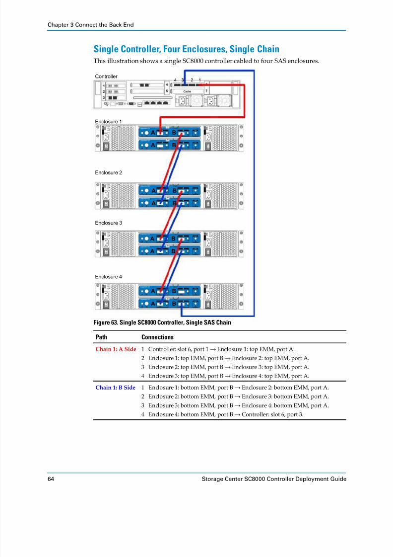
8/18/2019 Deployment Guide Sc8000
http://slidepdf.com/reader/full/deployment-guide-sc8000 74/218
Chapter 3 Connect the Back End
64 Storage Center SC8000 Controller Deployment Guide
Single Controller, Four Enclosures, Single ChainThis illustration shows a single SC8000 controller cabled to four SAS enclosures.
Figure 63. Single SC8000 Controller, Single SAS Chain
Path Connections
Chain 1: A Side 1 Controller: slot 6, port 1 → Enclosure 1: top EMM, port A.
2 Enclosure 1: top EMM, port B → Enclosure 2: top EMM, port A.
3 Enclosure 2: top EMM, port B → Enclosure 3: top EMM, port A.
4 Enclosure 3: top EMM, port B → Enclosure 4: top EMM, port A.
Chain
1:
B
Side 1 Enclosure 1:
bottom
EMM,
port
B
→ Enclosure
2:
bottom
EMM,
port
A.
2 Enclosure 2: bottom EMM, port B → Enclosure 3: bottom EMM, port A.
3 Enclosure 3: bottom EMM, port B → Enclosure 4: bottom EMM, port A.
4 Enclosure 4: bottom EMM, port B → Controller: slot 6, port 3.
Enclosure 1
Enclosure 2
Enclosure 3
Enclosure 4
Controller 4 3 2 1
A
A B
B
A
A B
B
A
A B
B
A
A B
B

8/18/2019 Deployment Guide Sc8000
http://slidepdf.com/reader/full/deployment-guide-sc8000 75/218
Connect SC200/SC220 Enclosures
Dell Compellent 65
Single Controller, Four Enclosures, Two IO Cards, Two Chains, LowProfile SASThis illustration shows a single SC8000 controller cabled to four SAS enclosures in two
chains using low profile SAS IO cards in low profile card slots. When cabling a second
chain of enclosures, use a second IO card to improve redundancy.
Figure 64. Single SC8000 Controller, Four SAS Enclosures, Two IO Cards, Two Chains, Low-profileSAS
Path Connections
Chain 1: A Side 1 Controller: slot 2, port 1 → Enclosure 1: top EMM, port A.
2 Enclosure 1: top EMM, port B → Enclosure 2: top EMM, port A.
Chain 1: B Side 1 Enclosure 1: bottom EMM, port B → Enclosure 2: bottom EMM, port A.
2 Enclosure 2: bottom EMM, port B → Controller: slot 3, port 3.
Chain 2:
A
Side 1 Controller: slot 2 port 3 → Enclosure 3: top EMM, port A.
2 Enclosure 3: top EMM, port B → Enclosure 4: top EMM, port A.
Chain 2: B Side 1 Enclosure 3: bottom EMM, port B → Enclosure 4: bottom EMM, port A.
2 Enclosure 4: bottom EMM, port B → Controller slot 3 port 1.
Enclosure 1
Enclosure 2
Enclosure 3
Enclosure 4
Controller
A
A B
B
A
A B
B
A
A B
B
A
A B
B
4321
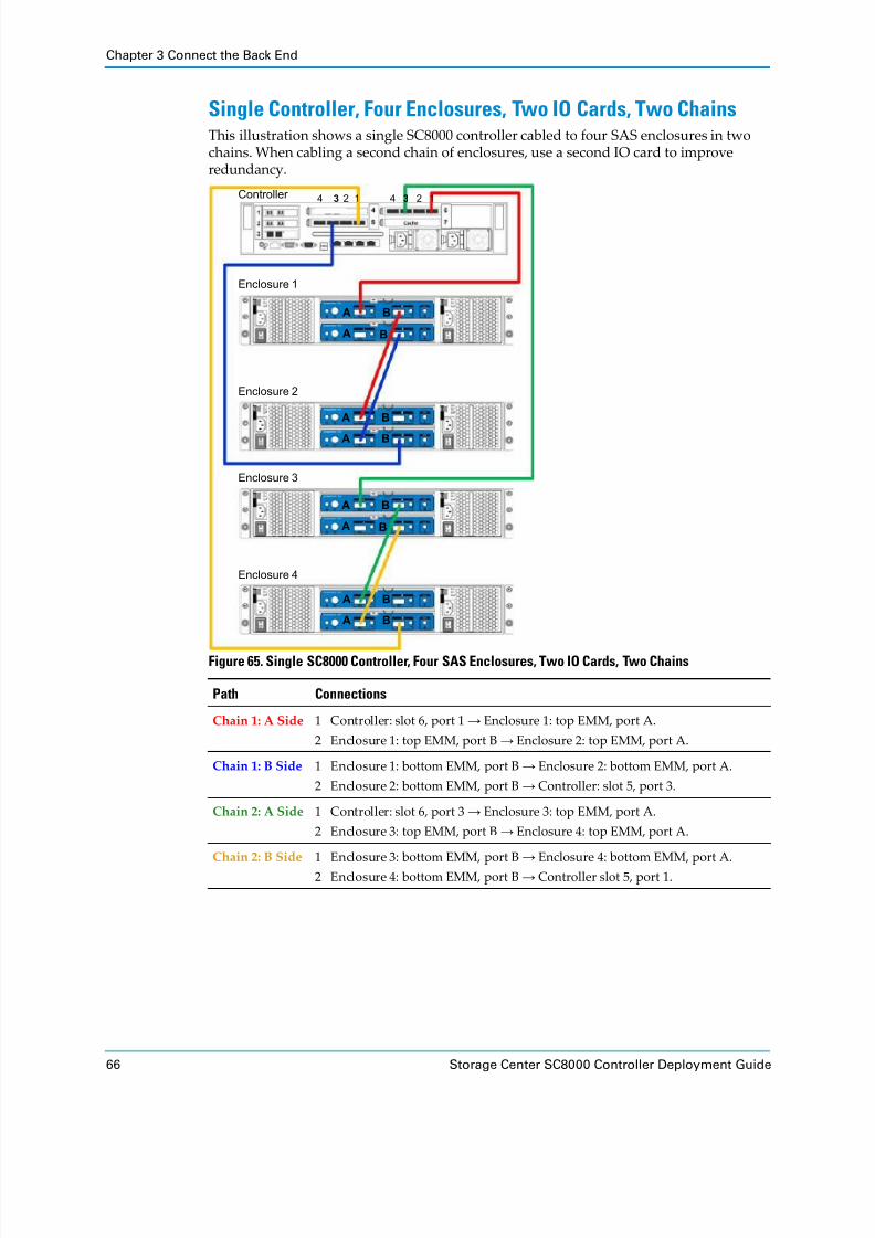
8/18/2019 Deployment Guide Sc8000
http://slidepdf.com/reader/full/deployment-guide-sc8000 76/218
Chapter 3 Connect the Back End
66 Storage Center SC8000 Controller Deployment Guide
Single Controller, Four Enclosures, Two IO Cards, Two ChainsThis illustration shows a single SC8000 controller cabled to four SAS enclosures in two
chains. When cabling a second chain of enclosures, use a second IO card to improve
redundancy.
Figure 65. Single SC8000 Controller, Four SAS Enclosures, Two IO Cards, Two Chains
Path Connections
Chain 1: A Side 1 Controller: slot 6, port 1 → Enclosure 1: top EMM, port A.
2 Enclosure 1: top EMM, port B → Enclosure 2: top EMM, port A.
Chain 1: B Side 1 Enclosure 1: bottom EMM, port B → Enclosure 2: bottom EMM, port A.
2 Enclosure 2: bottom EMM, port B → Controller: slot 5, port 3.
Chain 2: A Side 1 Controller: slot 6, port 3 → Enclosure 3: top EMM, port A.
2 Enclosure 3: top EMM, port B → Enclosure 4: top EMM, port A.
Chain 2: B Side 1 Enclosure 3: bottom EMM, port B → Enclosure 4: bottom EMM, port A.
2 Enclosure 4: bottom EMM, port B → Controller slot 5, port 1.
Enclosure 1
Enclosure 2
Enclosure 3
Enclosure 4
Controller 4 3 2 1
A
A B
B
A
A B
B
A
A B
B
A
A B
B
4 3 2 1

8/18/2019 Deployment Guide Sc8000
http://slidepdf.com/reader/full/deployment-guide-sc8000 77/218
Connect SC200/SC220 Enclosures
Dell Compellent 67
Dual Controllers, One Enclosure, Single Chain, Low Profile SASThis illustration shows two SC8000 controllers cabled to two 6 Gb enclosures using a low
profile SAS IO card in a low profile card slot and creating a single chain.
Figure 66. Dual SC8000 Controllers, One Enclosure, One Chain, Low Profile SAS
Note: In a single‐chain configuration, use SAS ports 2 (initiator) and 4 (target) to
create a redundant IPC connection. When you configure these ports using the IO
port wizard, set the port Purpose to Unknown.
Path Connections
IPC 1 Controller A: slot 3, port 2 → Controller B: slot 3, port 4.
2 Controller B: slot 3, port 2 → Controller A: slot 3, port 4.
Chain 1: A Side 1 Controller A: slot 3, port 1 → Enclosure: top EMM, port A.
2 Enclosure: top EMM, port B → Controller B: slot 3, port 3.
Chain 1: B Side 1 Controller B: slot 3, port 1 → Enclosure: bottom EMM, port A.
2 Enclosure: bottom EMM, port B → Controller A: slot 3, port 3.
Enclosure
Controller A
Controller B
A
A B
B
4321

8/18/2019 Deployment Guide Sc8000
http://slidepdf.com/reader/full/deployment-guide-sc8000 78/218

8/18/2019 Deployment Guide Sc8000
http://slidepdf.com/reader/full/deployment-guide-sc8000 79/218
Connect SC200/SC220 Enclosures
Dell Compellent 69
Dual Controllers, Two Enclosures, Single Chain, Low Profile SASThis illustration shows two SC8000 controllers cabled to two 6 Gb enclosures using a low
profile SAS IO card in a low profile card slot and creating a single chain.
Figure 68. Dual SC8000 Controllers, Two Enclosures, One Chain, Low Profile SAS
Note: In a single‐chain configuration, use SAS ports 2 (initiator) and 4 (target) to
create a redundant IPC connection. When you configure these ports using the IO
port wizard, set the port Purpose to Unknown.
Path Connections
IPC 1 Controller A: slot 3, port 2 → Controller B: slot 3, port 4.
2 Controller B: slot 3, port 2 → Controller A: slot 3, port 4.
Chain 1: A Side 1 Controller A: slot 3, port 1 → Enclosure 1: top EMM, port A.
2 Enclosure 1: top EMM, port B → Enclosure 2: top EMM, port A.
3 Enclosure 2: top EMM, port B → Controller B: slot 3, port 3.
Chain 1: B Side 1 Controller B: slot 3, port 1 → Enclosure 1: bottom EMM, port A.
2 Enclosure 1: bottom EMM, port B → Enclosure 2: bottom EMM, port A.
3 Enclosure 2: bottom EMM, port B → Controller A: slot 3, port 3.
Enclosure 1
Enclosure 2
Controller A
Controller B
4321
A
A B
B
A
A B
B

8/18/2019 Deployment Guide Sc8000
http://slidepdf.com/reader/full/deployment-guide-sc8000 80/218
Chapter 3 Connect the Back End
70 Storage Center SC8000 Controller Deployment Guide
Dual Controllers, Two Enclosures, Single ChainThis illustration shows two SC8000 controllers cabled to two SAS enclosures forming a
single chain. In a single‐chain configuration, use SAS ports 2 (initiator) and 4 (target) to
create a redundant IPC connection. When you configure these ports using the IO port wizard, set the port Purpose to Unknown.
Figure 69. Dual SC8000 Controllers, Two Enclosures, One Chain
Path Connections
IPC 1 Controller A: slot 6, port 2 → Controller B: slot 6, port 4.
2 Controller B: slot 6, port 2 → Controller A: slot 6, port 4.
Chain 1: A Side 1 Controller A: slot 6, port 1 → Enclosure 1: top EMM, port A.
2 Enclosure 1: top EMM, port B → Enclosure 2: top EMM, port A.
3 Enclosure 2: top EMM, port B → Controller B: slot 6, port 3.
Chain 1: B Side 1 Controller B: slot 6, port 1 → Enclosure 1: bottom EMM, port A.
2 Enclosure 1:
bottom
EMM,
port
B
→ Enclosure 2:
bottom
EMM,
port
A.
3 Enclosure 2: bottom EMM, port B → Controller A: slot 6, port 3.
Enclosure 1
Enclosure 2
Controller A
Controller B
4 3 2 1
A
A B
B
A
A B
B
4 3 2 1

8/18/2019 Deployment Guide Sc8000
http://slidepdf.com/reader/full/deployment-guide-sc8000 81/218

8/18/2019 Deployment Guide Sc8000
http://slidepdf.com/reader/full/deployment-guide-sc8000 82/218
Chapter 3 Connect the Back End
72 Storage Center SC8000 Controller Deployment Guide
Path Connections
Chain 1: A Side 1 Controller A: slot 2 port 1 → Enclosure 1: top EMM, port A.
2 Enclosure 1: top EMM, port B → Enclosure 2: top EMM, port A.
3 Enclosure 2: top EMM, port B → Controller B: slot 2, port 3.
Chain 1:
B
Side 1 Controller B:
slot
3 port
1 →
Enclosure 1:
bottom
EMM,
port
A.
2 Enclosure 1: bottom EMM, port B → Enclosure 2: bottom EMM, port A.
3 Enclosure 2: bottom EMM, port B → Controller A: slot 3, port 3.
Chain 2: A Side 1 Controller A: slot 2, port 3 → Enclosure 3: top EMM, port A.
2 Enclosure 3: top EMM, port B → Enclosure 4: top EMM, port A.
3 Enclosure 4: top EMM, port B → Controller B: slot 2, port 1.
Chain 2: B Side 1 Controller B: slot 3, port 3 → Enclosure 3: bottom EMM, port A.
2 Enclosure 3: bottom EMM, port B → Enclosure 4: bottom EMM, port A.
3 Enclosure 4: bottom EMM, port B → Controller A: slot 3, port 1.

8/18/2019 Deployment Guide Sc8000
http://slidepdf.com/reader/full/deployment-guide-sc8000 83/218
Connect SC200/SC220 Enclosures
Dell Compellent 73
Dual Controllers, Four Enclosures, Two ChainsThis illustration shows two SC8000 controllers cabled to two SAS enclosures. Each
enclosure is on a separate chain. When two chains are used, IPC is optional.
Figure 71. Dual SC8000 Controllers, Four Enclosures, Two Chains
Path Connections
Chain 1: A Side 1 Controller A: slot 6, port 1 → Enclosure 1: top EMM, port A.
2 Enclosure 1: top EMM, port B → Enclosure 2: top EMM, port A.
3 Enclosure 2: top EMM, port B → Controller B: slot 6, port 3.
Chain 1: B Side 1 Controller B: slot 5, port 1 → Enclosure 1: bottom EMM, port A.
2 Enclosure 1:
bottom
EMM,
port
B
→ Enclosure
2:
bottom
EMM,
port
A.
3 Enclosure 2: bottom EMM, port B → Controller A: slot 5, port 3.
Chain 2: A Side 1 Controller A: slot 6, port 3 → Enclosure 3: top EMM, port A.
2 Enclosure 3: top EMM, port B → Enclosure 4: top EMM, port A.
3 Enclosure 4: top EMM, port B → Controller B: slot 6, port 1.
Controller A
Controller B
Enclosure 1
Enclosure 2
Enclosure 3
Enclosure 4
4 3 2 1
4 3 2 14 3 2 1
4 3 2 1
A B
A B
A B
A B
A B
A B
A B
A B

8/18/2019 Deployment Guide Sc8000
http://slidepdf.com/reader/full/deployment-guide-sc8000 84/218
Chapter 3 Connect the Back End
74 Storage Center SC8000 Controller Deployment Guide
Dual Controllers, Eight Enclosures, Two ChainsThis illustration shows two SC8000 controllers cabled to eight 6 Gb enclosures using two
chains. To add redundancy with multiple IO cards, add a second SAS IO card. Create the
A‐side of each chain on the IO card in slot 6 and create the B‐side of each chain on the IO
card in slot 5. If an IO card, cable, enclosure, or controller fails, at least one side of a loop
continues operating. IPC is optional in this configuration.
Figure 72. Dual SC8000 Controllers, Eight Enclosures, Two Chains
Chain 2: B Side 1 Controller B: slot 5, port 3 → Enclosure 3: bottom EMM, port A.
2 Enclosure 3: bottom EMM, port B → Enclosure 4: bottom EMM, port A.
3 Enclosure 4: bottom EMM, port B → Controller A: slot 5, port 1.
Path Connections
IPC (Optional) Create IPC connections between both controllers on ports 2 and 4 of each IO card.
Chain 1: A Side 1 Controller A: slot 6, port 1 → Enclosure 1: top EMM, port A.
2 Starting with Enclosure 1, daisy‐chain the A side of Chain 1 by cabling: top
EMM, port B → next enclosure down: top EMM, port A.
3 Finish with Enclosure 4: top EMM, port B → Controller B: slot 6, port 3.
Path Connections
Enclosure 1
Enclosure 2
Enclosure 3
Enclosure 4
Controller B
Controller A
Enclosure 5
Enclosure 6
Enclosure 7
Enclosure 8
4 3 2 14 3 2 1
4 3 2 1 4 3 2 1
A
A B
B
A
A B
B
A
A B
B
A
A B
B A
A B
B
A
A B
B
A
A B
B
A
A B
B

8/18/2019 Deployment Guide Sc8000
http://slidepdf.com/reader/full/deployment-guide-sc8000 85/218
Connect SC280 Enclosures
Dell Compellent 75
Connect SC280 EnclosuresThis section shows common cabling between the SC8000 controller and SC280 SAS
enclosures. Locate the scenario that most closely matches the Storage Center you are
configuring and follow the instructions, modifying them as necessary.
A cabling chain for the SC280 can contain up to two enclosures of 84 SAS drives each (168
drives total). Each chain must contain the same type of enclosures, such as all SC280. Do
not mix enclosure types in a chain.
Each SAS IO card supports up to two chains of enclosures. All enclosures attached to the
same SAS IO card must be running at 6 Gb.
SC280 enclosure chains are cabled as follows.
Side A: Enclosures are connected from B port to A port, using the left EMMs.
Side B: Enclosures are connected from A port to B port, using the right EMMs.
Chain 1: B Side 1 Controller A: slot 5, port 3 → Enclosure 4: bottom EMM, port B.
2 Starting with Enclosure 4, daisy‐chain the B side of Chain 1 by cabling: bottom
EMM, port A → next enclosure up: bottom EMM, port B.
3 Finish with Enclosure 1: bottom EMM, port A → Controller B: slot 5, port 1.
Chain 2:
A
Side 1 Controller A: slot 6, port 3 → Enclosure 5: top EMM, port A.
2 Starting with Enclosure 5, daisy‐chain the A side of Chain 2 by cabling: top
EMM, port B → next enclosure down: top EMM, port A.
3 Finish with Enclosure 8: top, port B → Controller B: slot 6, port 1.
Chain 2: B Side 1 Controller A: slot 5, port 1 → Enclosure 8: bottom EMM, port B.
2 Starting with Enclosure 8, daisy‐chain the B side of Chain 2 by cabling: bottom
EMM, port A → next enclosure up: bottom EMM, port B.
3 Finish with Enclosure 5: bottom, port A → Controller B: slot 5, port 3.
Path Connections
Path High-Level Steps
Chain 1: Side A 1 Connect controller port 1 to the first enclosure, left EMM , port C.
2 Connect the remaining enclosures in series from B port to A port using the left EMMs.
3 If the Storage Center has dual controllers, connect the last enclosure, left EMM , port C to the second controller, port 3.
Chain 1: Side B 1 Connect controller port 3 to the last enclosure, right EMM, port C.
2 Connect the remaining enclosures in series from B port to A port using the right EMM.
3 If the Storage Center has dual controllers, connect the top enclosure, right
EMM, port C to the second controller, port 1.
Note: The cabling illustrations in this chapter refer to enclosures as Enclosure 1, Enclosure 2, and so on. The numbers shown in the illustrations may not match the
Index number assigned by the System Manager. Storage Center assigns an Index
only after the system is powered up and at least one drive is assigned to a Disk
Folder.

8/18/2019 Deployment Guide Sc8000
http://slidepdf.com/reader/full/deployment-guide-sc8000 86/218
Chapter 3 Connect the Back End
76 Storage Center SC8000 Controller Deployment Guide
See Also
SAS Enclosure Cabling Guidelines on page 55
Single Controller, Single SC280 EnclosureThis illustration shows an SC8000 controller cabled to a single SC280 enclosure.
Figure 73. Single SC8000 Controller, Single SC280 Enclosure
Path Connections
Chain 1: A Side Controller: slot 3, port 1 → Enclosure: left EMM, port C.
Chain 1: B Side Controller: slot 3, port 3 → Enclosure: right EMM, port C.
A B
1 3 42
C A B C
4 3 2 1

8/18/2019 Deployment Guide Sc8000
http://slidepdf.com/reader/full/deployment-guide-sc8000 87/218

8/18/2019 Deployment Guide Sc8000
http://slidepdf.com/reader/full/deployment-guide-sc8000 88/218
Chapter 3 Connect the Back End
78 Storage Center SC8000 Controller Deployment Guide
Dual Controller, Single SC280 EnclosureThis illustration shows two SC8000 controllers cabled to one SC280 enclosure in a single
chain.
Figure 75. Dual SC8000 Controllers, One SC280 Enclosure, One Chain
Note: In a single‐chain configuration, use SAS ports 2 (initiator) and 4 (target) to
create a redundant IPC connection. When you configure these ports using the IO
port wizard, set the port Purpose to Unknown.
Path Connections
IPC 1 Controller A: slot 3, port 2 → Controller B: slot 3, port 4.
2 Controller B: slot 3, port 2 → Controller A: slot 3, port 4.
Chain 1: A Side 1 Controller A: slot 3, port 1 → Enclosure: left EMM, port C.
2 Enclosure: left EMM, port B → Controller B: slot 3, port 3.
Chain 1: B Side 1 Controller B: slot 3, port 1 → Enclosure: right EMM, port C.
2 Enclosure: right EMM, port B → Controller A: slot 3, port 3.
Enclosure
Controller A
Controller B
A B
1 3 42
C A B C
1 3 42 4 3 2 1
4 3 2 1
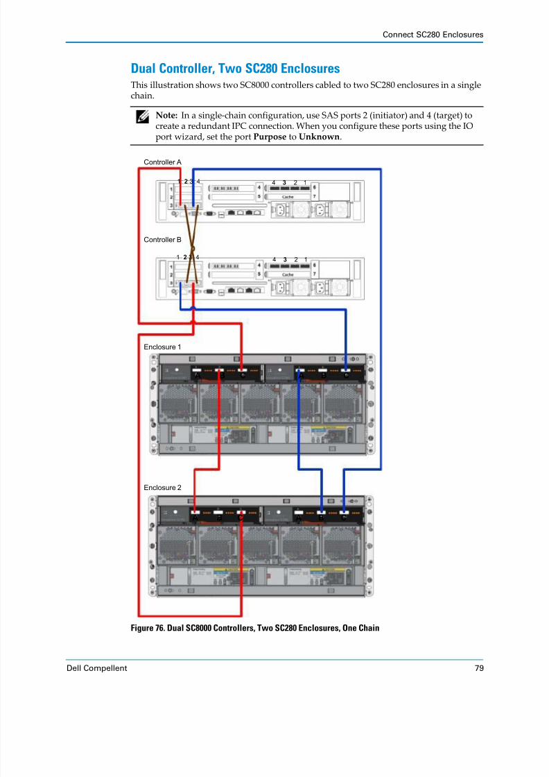
8/18/2019 Deployment Guide Sc8000
http://slidepdf.com/reader/full/deployment-guide-sc8000 89/218
Connect SC280 Enclosures
Dell Compellent 79
Dual Controller, Two SC280 EnclosuresThis illustration shows two SC8000 controllers cabled to two SC280 enclosures in a single
chain.
Figure 76. Dual SC8000 Controllers, Two SC280 Enclosures, One Chain
Note: In a single‐chain configuration, use SAS ports 2 (initiator) and 4 (target) to
create a redundant IPC connection. When you configure these ports using the IO
port wizard, set the port Purpose to Unknown.
Controller A
Controller B
Enclosure 1
Enclosure 2
A B
1 3 42
C A B C
1 3 42
A B C A B C
4 3 2 1
4 3 2 1

8/18/2019 Deployment Guide Sc8000
http://slidepdf.com/reader/full/deployment-guide-sc8000 90/218
Chapter 3 Connect the Back End
80 Storage Center SC8000 Controller Deployment Guide
Path Connections
IPC 1 Controller A: slot 3, port 2 → Controller B: slot 3, port 4.
2 Controller B: slot 3, port 2 → Controller A: slot 3, port 4.
Chain 1: A Side 1 Controller A: slot 3, port 1 → Enclosure: 1 left EMM, port C.
2 Enclosure 1:
left
EMM,
port
B
→ Enclosure:
2 left
EMM,
port
A.
3 Enclosure 2: left EMM, port C → Controller B: slot 3, port 3.
Chain 1: B Side 1 Controller B: slot 3, port 1 → Enclosure: 1 right EMM, port C.
2 Enclosure 1: right EMM, port A → Enclosure: 2 right EMM, port B.
3 Enclosure 2: right EMM, port C → Controller A: slot 3, port 3.

8/18/2019 Deployment Guide Sc8000
http://slidepdf.com/reader/full/deployment-guide-sc8000 91/218

8/18/2019 Deployment Guide Sc8000
http://slidepdf.com/reader/full/deployment-guide-sc8000 92/218
Chapter 3 Connect the Back End
82 Storage Center SC8000 Controller Deployment Guide
Figure 77. Dual SC8000 Controllers, Mixed Enclosures, Two Chains
Enclosure 1
Enclosure 2
Enclosure 3
Enclosure 4
Controller B
Controller A1 3 42
1 3 42
4 3 2 1
4 3 2 1

8/18/2019 Deployment Guide Sc8000
http://slidepdf.com/reader/full/deployment-guide-sc8000 93/218
Connect SC280 Enclosures
Dell Compellent 83
Path Connections
IPC (Optional) Create IPC connections between both controllers on ports 2 and 4 of each SAS IO card.
SC280 Enclosures
Chain 1:
A
Side 1 Controller A: slot 2, port 1 → Enclosure 1: left EMM, port C.
2 Enclosure 1 left EMM, port B → Enclosure 2: left EMM, port A.
3 Finish with Enclosure 2: left EMM, port C → Controller B: slot 2, port 3.
Chain 1: B Side 1 Controller B: slot 3, port 1 → Enclosure 1: right EMM, port C.
2 Enclosure 1 right EMM, port A → Enclosure 2: right EMM, port B.
3 Finish with Enclosure 2: right EMM, port C → Controller A: slot 3, port 3.
SC200/220 Enclosures
Chain 2: A Side 1 Controller A: slot 2, port 3 → Enclosure 3: top EMM, port A.
2 Enclosure 3 top EMM, port B → Enclosure 4: top EMM, port A.
3 Finish with Enclosure 4: top EMM, port B → Controller B: slot 2, port 1.
Chain 2:
B
Side 1 Controller A: slot 3, port 1 → Enclosure 4: bottom EMM, port B.
2 Enclosure 4 bottom EMM, port A → Enclosure 3: bottom EMM, port B.
3 Finish with Enclosure 3: bottom EMM, port A → Controller B: slot 3, port 3.

8/18/2019 Deployment Guide Sc8000
http://slidepdf.com/reader/full/deployment-guide-sc8000 94/218
Chapter 3 Connect the Back End
84 Storage Center SC8000 Controller Deployment Guide
Connect EN-SASx6x12/24 EnclosuresThis section shows common cabling between the SC8000 controller and EN‐SASx6x12/24
SAS enclosures. Locate the scenario that most closely matches the Storage Center you are
configuring and follow the instructions, modifying them as necessary.
A SAS cabling chain can contain up to 14 enclosures and up to 168 6 Gbps SAS drives. Each
chain must
contain
the
same
type
of
enclosures,
such
as
all
EN
‐SAS
x6x12/24.
Do
not
mix
enclosure types in a chain.
EN‐SASx6x12/24 SAS enclosure chains are cabled as follows.
Side A: Enclosures are connected from B port to A port, using the top SBBs.
Side B: Enclosures are connected from A port to B port, using the bottom SBBs.
See Also
SAS Enclosure Cabling Guidelines on page 55
Path High-Level Steps
Chain 1: Side A 1 Connect controller port 1 to the first enclosure, top SBB , port C.
2 Connect the remaining enclosures in series from B port to A port using the top
SBBs.
3 If the Storage Center has dual‐controllers, connect the last enclosure, top SBB ,
port C to the second controller, port 3.
Chain 1: Side B 1 Connect controller port 3 to the last enclosure, bottom SBB , port C.
2 Connect the remaining enclosures in series from B port to A port using the
bottom SBB.
3 If the Storage Center has dual‐controllers, connect the top enclosure, bottom
SBB , port C to the second controller, port 1.
Note: The cabling illustrations in this chapter refer to enclosures as Enclosure 1, Enclosure 2, and so on. The numbers shown in the illustrations may not match the
Index number assigned by the System Manager. Storage Center which assigns an
Index only after the system is powered up and at least one drive is assigned to a Disk
Folder.

8/18/2019 Deployment Guide Sc8000
http://slidepdf.com/reader/full/deployment-guide-sc8000 95/218

8/18/2019 Deployment Guide Sc8000
http://slidepdf.com/reader/full/deployment-guide-sc8000 96/218
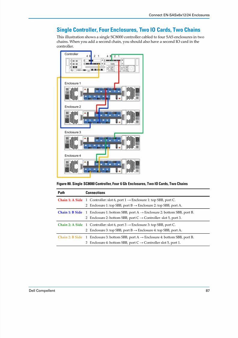
8/18/2019 Deployment Guide Sc8000
http://slidepdf.com/reader/full/deployment-guide-sc8000 97/218
Connect EN-SASx6x12/24 Enclosures
Dell Compellent 87
Single Controller, Four Enclosures, Two IO Cards, Two ChainsThis illustration shows a single SC8000 controller cabled to four SAS enclosures in two
chains. When you add a second chain, you should also have a second IO card in the
controller.
Figure 80. Single SC8000 Controller, Four 6 Gb Enclosures, Two IO Cards, Two Chains
Path Connections
Chain 1: A Side 1 Controller: slot 6, port 1 → Enclosure 1: top SBB, port C.
2 Enclosure 1: top SBB, port B → Enclosure 2: top SBB, port A.
Chain 1: B Side 1 Enclosure 1: bottom SBB, port A → Enclosure 2: bottom SBB, port B.
2 Enclosure 2: bottom SBB, port C → Controller: slot 5, port 3.
Chain 2: A Side 1 Controller: slot 6, port 3 → Enclosure 3: top SBB, port C.
2 Enclosure 3: top SBB, port B → Enclosure 4: top SBB, port A.
Chain 2:
B
Side 1 Enclosure 3: bottom SBB, port A → Enclosure 4: bottom SBB, port B.
2 Enclosure 4: bottom SBB, port C → Controller slot 5, port 1.
Enclosure 1
Enclosure 2
Enclosure 3
Enclosure 4
Controller 4 3 2 14 3 2 1

8/18/2019 Deployment Guide Sc8000
http://slidepdf.com/reader/full/deployment-guide-sc8000 98/218
Chapter 3 Connect the Back End
88 Storage Center SC8000 Controller Deployment Guide
Dual Controllers, Two Enclosures, Single ChainThis illustration shows two SC8000 controllers cabled to two SAS enclosures forming a
single chain. In a single‐chain configuration, use SAS ports 2 and 4 to create a redundant IPC connection. When you configure these ports using the IO port wizard, set the port Purpose to Unknown.
Figure 81. Dual SC8000 Controllers, Two Enclosures, One Chain
Path Connections
IPC 1 Controller A: slot 6, port 2 → Controller B: slot 6, port 4.
2 Controller B: slot 6, port 2 → Controller A: slot 6, port 4.
Chain 1: A Side 1 Controller A: slot 6, port 1 → Enclosure 1: top SBB, port C.
2 Enclosure 1: top SBB, port B → Enclosure 2: top SBB, port A.
3 Enclosure 2: top SBB, port C → Controller B: slot 6, port 3.
Chain 1: B Side 1 Controller B: slot 6, port 1 → Enclosure 1: bottom SBB, port C.
2 Enclosure 1: bottom SBB, port A → Enclosure 2: bottom SBB, port B.
3 Enclosure 2: bottom SBB, port C → Controller A: slot 6, port 3.
Enclosure 1
Enclosure 2
Controller A
Controller B
4 3 2 1

8/18/2019 Deployment Guide Sc8000
http://slidepdf.com/reader/full/deployment-guide-sc8000 99/218
Connect EN-SASx6x12/24 Enclosures
Dell Compellent 89
Dual Controllers, Four Enclosures, Two Chains
This illustration shows two SC8000 controllers cabled to two SAS enclosures. Each
enclosure is on a separate chain. When two chains are used, IPC is optional.
Figure 82. Dual SC8000 Controllers, Two Enclosures, Two Chains
Path Connections
Chain 1: A Side 1 Controller A: slot 6, port 1 → Enclosure 1: top SBB, port C.
2 Enclosure 1: top SBB, port B → Enclosure 2: top SBB, port A.
3 Enclosure 2: top SBB, port C → Controller B: slot 6, port 3.
Chain 1: B Side 1 Controller A: slot 5, port 3 → Enclosure 2: bottom SBB, port C.
2 Enclosure 2: bottom SBB, port B → Enclosure 1: bottom SBB, port A.
3 Enclosure 1: bottom SBB, port C → Controller B: slot 5, port 1.
Chain 2: A Side 1 Controller A: slot 6 port 3 → Enclosure 3: top SBB, port C.
2 Enclosure 3: top SBB, port B → Enclosure 4: top SBB, port A.
3 Enclosure 4: top SBB, port C → Controller B: slot 6, port 1.
Chain 2: B Side 1 Controller A: slot 5 port 1→ Enclosure 4: bottom SBB, port C.
2 Enclosure 4: bottom SBB, port B → Enclosure 3: bottom SBB, port A.
3 Enclosure 3: bottom SBB, port C → Controller B: slot 5, port 3.
4 3 2 14 3 2 1Controller A
Controller B
Enclosure 1
Enclosure 2
Enclosure 3
Enclosure 4

8/18/2019 Deployment Guide Sc8000
http://slidepdf.com/reader/full/deployment-guide-sc8000 100/218
Chapter 3 Connect the Back End
90 Storage Center SC8000 Controller Deployment Guide
Dual Controllers, Four Enclosures, Single ChainThis illustration shows two SC8000 controllers with one SAS IO Card cabled to four SAS
enclosures. In a single‐chain configuration, use SAS ports 2 and 4 to create a redundant IPC
connection. When you configure these ports using the IO port wizard, set the port Purpose
to Unknown.
Figure 83. Dual SC8000 Controllers, Four Enclosures, One IO Card, One Chain
Path Connections
IPC 1 Controller A: slot 6, port 2 → Controller B: slot 6, port 4.
2 Controller B: slot 6, port 2 → Controller A: slot 6, port 4.
Chain 1: A Side 1 Controller A: slot 6, port 1 → Enclosure 1: top SBB, port C.
2 Enclosure 1, top SBB, port B → Enclosure 2, top SBB, port A.
3 Continue to daisy‐chain enclosures: top SBB, port B → next enclosure down: top SBB, port A.
4 Enclosure 4: top SBB, port C → Controller B: slot 6, port 3.
Chain 1: B Side 1 Controller B: slot 6, port 1 → Enclosure 1: bottom SBB, port C.
2 Enclosure 1: bottom SBB, port A → Enclosure 2: bottom SBB, port B.
3 Continue to daisy‐chain enclosures: bottom SBB, port A → next enclosure
down: bottom SBB, port B.
4 Enclosure 4: bottom SBB, port C → Controller A: slot 6, port 3.
Enclosure 1
Enclosure 2
Enclosure 3
Enclosure 4
Controller B
Controller A4 2 13

8/18/2019 Deployment Guide Sc8000
http://slidepdf.com/reader/full/deployment-guide-sc8000 101/218
Connect EN-SASx6x12/24 Enclosures
Dell Compellent 91
Dual Controllers, Eight Enclosures, Two Chains
This illustration shows two SC8000 controllers cabled to eight SAS enclosures in two
chains. To add redundancy with multiple IO cards, add a second SAS IO card. Create the
A‐sides of each chain on the IO card in slot 6 and create the B‐sides of each chain on the IO
card in slot 5. If an IO card, cable, enclosure, or controller fails, at least one side of a chain
continues operating. IPC is optional in this configuration.
Figure 84. Dual SC8000 Controllers, Eight Enclosures, Two Chains
Path Connections
IPC (Optional) Create IPC connections between both controllers on ports 2 and 4 of each IO card.
Chain 1: A Side 1 Controller A: slot 6, port 1 → Enclosure 1: top SBB, port C.
2 Starting with Enclosure 1, daisy‐chain the A side of Chain 1 by cabling: top
SBB, port B → next enclosure down: top SBB, port A.
3 Finish with Enclosure 4: top SBB, port C ? Controller B: slot 6, port 3.
Chain 1: B Side 1 Controller A: slot 5, port 3 → Enclosure 4: bottom SBB, port C.
2 Starting with Enclosure 4, daisy‐chain the B side of Chain 1 by cabling: bottom
SBB, port B → next enclosure up: bottom SBB, port A.
3 Finish with Enclosure 1: bottom SBB, port C → Controller B: slot 5, port 1.
Enclosure 1
Enclosure 2
Enclosure 3
Enclosure 4
Controller
Controller A
Enclosure 5
Enclosure 6
Enclosure 7
Enclosure 8
4 2 13
4 2 13

8/18/2019 Deployment Guide Sc8000
http://slidepdf.com/reader/full/deployment-guide-sc8000 102/218
Chapter 3 Connect the Back End
92 Storage Center SC8000 Controller Deployment Guide
Chain 2: A Side 1 Controller A: slot 6, port 3→ Enclosure 5: top SBB, port C.
2 Starting with Enclosure 5, daisy‐chain the A side of Chain 2 by cabling: top
SBB, port B → next enclosure down: top SBB, port A.
3 Finish with Enclosure 8: top SBB, port C ? Controller B: slot 6, port 1.
Chain 2:
B
Side 1 Controller A: slot 5, port 1 → Enclosure 8: bottom SBB, port C.
2 Starting with Enclosure 8, daisy‐chain the B side of Chain 2 by cabling: bottom
SBB, port B → next enclosure up: bottom SBB, port A.
3 Finish with Enclosure 5: bottom SBB, port C → Controller B: slot 5, port 3.
Path Connections

8/18/2019 Deployment Guide Sc8000
http://slidepdf.com/reader/full/deployment-guide-sc8000 103/218
Label the Back-End Cables
Dell Compellent 93
Label the Back-End CablesLabel the back‐end cables that connect controllers to enclosures to indicate the chain
number and side (A or B). Pre‐made labels are provided for SC200/220 enclosures. Labels are not provided for EN‐SASx6x12/24 enclosures, so labels must be created manually for cables that connect to those enclosures.
Prerequisites
If the Storage Center has EN‐SASx6x12/24 enclosures, you must have a label maker, or four
blank labels and a writing utensil.
Steps
1 Locate or create labels for the back‐end cables.
EN‐SASx6x12/24 enclosures: Create labels that label the purpose (Backend), chain
number, and side (A or B).
Example: Backend 1A
SC200/220 enclosures: Locate the back‐end cable labels that shipped with the
enclosures. The pre‐made labels include the purpose (Backend), chain number, and
side (A or B).
Figure 85. SC200/220 Back-End Cable Label
Note: Cables that connect one enclosure to another do not need to be labeled.

8/18/2019 Deployment Guide Sc8000
http://slidepdf.com/reader/full/deployment-guide-sc8000 104/218
Chapter 3 Connect the Back End
94 Storage Center SC8000 Controller Deployment Guide
2 Apply cable labels to both ends of each SAS cable that connects a controller to an
enclosure.
a Near the connector, align the label perpendicular to the cable and affix it starting
with the top edge of the label.
Figure 86. Align Cable Label
b Wrap the label around the cable until it fully encircles the cable. The bottom of each
pre‐made label is clear so that it does not obscure the text.
Figure 87. Wrap Cable Label
c Apply a matching label to the other end of the cable.

8/18/2019 Deployment Guide Sc8000
http://slidepdf.com/reader/full/deployment-guide-sc8000 105/218
Dell Compellent 95
4 Connect the Front End
Front‐end cabling refers to connections between the controller and the server. Front‐end
connections can be made using iSCSI, Fibre Channel, or Fibre Channel over Ethernet (FCoE). Dell Compellent recommends connecting servers to the controller(s) using the
most redundant options available.
Contents
Types of
Redundancy
for
Front
‐End
Connections .
. . . . . . . . . . . . . . . . . . . . . . . . . . . . . . .
95Multipath IO . . . . . . . . . . . . . . . . . . . . . . . . . . . . . . . . . . . . . . . . . . . . . . . . . . . . . . . . . . . . . . . . 96
Front‐End Connectivity Modes . . . . . . . . . . . . . . . . . . . . . . . . . . . . . . . . . . . . . . . . . . . . . . . . 96
Fibre Channel Zoning . . . . . . . . . . . . . . . . . . . . . . . . . . . . . . . . . . . . . . . . . . . . . . . . . . . . . . . 102
Connect the Front End for a Single‐Controller Storage Center . . . . . . . . . . . . . . . . . . . . 103
Connect the Front End for a Dual‐Controller Storage Center . . . . . . . . . . . . . . . . . . . . . 105
Label the Front‐End Cables . . . . . . . . . . . . . . . . . . . . . . . . . . . . . . . . . . . . . . . . . . . . . . . . . . 116
Types of Redundancy for Front-End ConnectionsFront‐end redundancy is achieved by eliminating single points of failure that could cause
a server to lose connectivity to the Storage Center.
Depending on how the Storage Center is configured, the following types of redundancy
are available.
Path redundancy: When multiple paths are available from a server to a Storage Center, a server configured for multipath IO (MPIO) can use multiple paths for IO. If a path
fails, the server continues to use the remaining active path(s).
Controller redundancy: If one controller fails in a dual‐controller Storage Center, the
front‐end ports fail over to the functioning controller. Both front‐end connectivity
modes (legacy mode and virtual port mode) provide controller redundancy.
Port redundancy: In virtual port mode, if a port goes down because it is disconnected
or there is a hardware failure, the port can fail over to another functioning port in the
same fault domain. Port redundancy is available for single‐controller and dual‐controller Storage Centers operating in virtual port mode.
See Also
Multipath IO on page 96
Legacy Mode on page 99
Virtual Port Mode on page 97

8/18/2019 Deployment Guide Sc8000
http://slidepdf.com/reader/full/deployment-guide-sc8000 106/218

8/18/2019 Deployment Guide Sc8000
http://slidepdf.com/reader/full/deployment-guide-sc8000 107/218
Front-End Connectivity Modes
Dell Compellent 97
Virtual Port ModeVirtual port mode provides port and controller redundancy by connecting multiple active
ports to each Fibre Channel or Ethernet switch.
In virtual port mode, each physical port has a WWN (World Wide Name), and is also
assigned an additional virtual WWN. Servers target only the virtual WWNs. During
normal conditions, all ports process IO. If a port or controller fails, a virtual WWN can be
moved to another physical WWN in the same fault domain. When the failure is resolved
and ports are rebalanced, the virtual port returns to the preferred physical port.
Virtual port mode provides the following advantages over legacy mode:
Increased performance: Because all ports are active, additional front‐end bandwidth is available without sacrificing redundancy.
Improved redundancy: Ports can fail over individually instead of by controller.
Simplified
iSCSI
configuration:
Each
fault
domain
has
an
iSCSI
control
port
that
coordinates discovery of the iSCSI ports in the domain. When a server targets the iSCSI port IP address, it automatically discovers all ports in the fault domain.
Fault Domains in Virtual Port Mode
Fault domains group front‐end ports that are connected to the same Fibre Channel fabric
or Ethernet network. Ports that belong to the same fault domain can fail over to each other because they have the same connectivity.
The following requirements apply to fault domains in virtual port mode:
A separate fault domain must be created for each front‐end Fibre Channel fabric or Ethernet network.
A
fault
domain
must
contain
a
single
type
of
transport
media
(FC
or
iSCSI,
but
not
both).
Dell Compellent recommends configuring at least two connections from each controller to each Fibre Channel or Ethernet network (fault domain).
Requirements for Virtual Port Mode
The following requirements must be met to configure a Storage Center in virtual port mode.
Note: Dell Compellent strongly recommends using virtual port mode unless the
network environment does not meet the requirements for virtual port mode.
Requirement Description
License The Storage Center must be licensed for virtual port mode.
Switches Front‐
end
ports
must
be
connected
to
Fibre
Channel
or
Ethernet
switches;
servers cannot be directly connected to controller front‐end ports.

8/18/2019 Deployment Guide Sc8000
http://slidepdf.com/reader/full/deployment-guide-sc8000 108/218
Chapter 4 Connect the Front End
98 Storage Center SC8000 Controller Deployment Guide
See Also
Fibre Channel Zoning on page 102
Example Virtual Port Mode ConfigurationThe following figure shows a dual‐controller Storage Center in virtual port mode
connected to a Fibre Channel server with a single fault domain. All ports belong to a single
fault domain because they are connected to the same FC switch.
Figure 88. Virtual Ports Example with FC
The following table summarizes the failover behaviors for this configuration.
Multipathing If multiple active paths are available to a server, the server must be
configured for MPIO to use more than one path simultaneously.
iSCSI networks • NAT must be disabled for iSCSI replication traffic.
• CHAP authentication must be disabled.
Fibre Channel fabrics • The FC topology must be switched fabric. Point‐to‐point and arbitrated
loop topologies are not supported.
• FC switches must be zoned to meet the virtual port mode zoning
requirements.
• FC switches must support N_Port ID Virtualization (NPIV).
• Persistent FCID must be disabled on FC switches.
Note: AIX servers are not supported.
Note: To use both primary paths simultaneously, the server must be configured to
use MPIO.
Scenario Failover Behavior
Normal operating conditions All ports are active and pass IO.
Controller A fails Virtual ports on controller A fail over by moving to physical ports on controller B.
Controller B fails Virtual ports on controller B fail over by moving to physical ports on
controller A.
A single port fails The virtual port associated with the failed physical port moves to
another physical port in the fault domain.
Requirement Description
FC Switch
Server
Controller A Controller B
Active Ports

8/18/2019 Deployment Guide Sc8000
http://slidepdf.com/reader/full/deployment-guide-sc8000 109/218
Front-End Connectivity Modes
Dell Compellent 99
Legacy ModeLegacy mode provides controller redundancy for a dual‐controller Storage Center by
connecting multiple primary and reserved ports to each Fibre Channel or Ethernet switch.
In legacy mode, each primary port on a controller is paired with a corresponding reserved
port on the other controller. During normal conditions, the primary ports process IO and
the reserved
ports
are
in
standby
mode.
If
a controller
fails,
the
primary
ports
fail
over
to
the corresponding reserved ports on the other controller. This approach ensures that servers connected to the switch do not lose connectivity if one of the controllers fails. For optimal performance, the primary ports should be evenly distributed across both
controllers. When possible, front‐end connections should be made to separate controller IO
cards to improve redundancy.
Fault Domains in Legacy Mode
Each pair of primary and reserved ports is grouped into a fault domain in the Storage
Center software. The fault domain determines which ports are allowed to fail over to each
other.
The following requirements apply to fault domains in legacy mode on a dual‐controller
Storage Center:
A fault domain must contain a one type of transport media (FC or iSCSI, but not both).
A fault domain must contain one primary port and one reserved port.
The reserved port must be located on a different controller than the primary port.
Requirements for Legacy Mode
The following requirements must be met to configure a Storage Center in legacy mode.
See Also
Fibre Channel Zoning on page 102
Note: For a single‐controller Storage Center, only one fault domain is required for each transport type (FC or iSCSI) because there are no reserved ports.
Requirement DescriptionController front‐end
portsEach controller must have enough front‐end ports to connect two paths to
each Fibre Channel or Ethernet switch.
Multipathing If multiple active paths are available to a server, the server must be
configured for MPIO to use more than one path simultaneously.
Fibre Channel zoning FC switches must be zoned to meet the legacy mode zoning requirements.

8/18/2019 Deployment Guide Sc8000
http://slidepdf.com/reader/full/deployment-guide-sc8000 110/218
Chapter 4 Connect the Front End
100 Storage Center SC8000 Controller Deployment Guide
Example Legacy Mode Configuration
The following figure shows a dual‐controller Storage Center in legacy mode connected to
a Fibre Channel server with two fault domains. Fault domain 1 (shown in orange) is
comprised of primary port P1 on controller A and reserved port R1 on controller B. Fault domain 2 (shown in green) is comprised of primary port P2 on controller B and reserved
port R2 on controller A.
Figure 89. Legacy Mode Example with FC
The following table summarizes the failover behaviors for this configuration.
Note: To use multiple paths simultaneously, the server must be configured to use
MPIO.
Scenario Failover Behavior
Normal operating conditions • Primary ports P1 and P2 (both fault domains) pass IO.
• Reserved ports R1 and R2 remain in a standby mode until a
controller failure.
Controller A fails In fault domain 1, primary port P1 fails over to reserved port R1.
Controller B fails In fault domain 2, primary port P2 fails over to reserved port R2.
A single port fails The port does not fail over because there was no controller failure. If a second path is available, MPIO software on the server provides fault tolerance by sending IO to the functioning port in the other fault domain.
Controller A
FC Switch
Server
Controller B
Primary Port — P2
Primary Port — P1 Reserved Port — R1
Reserved Port — R2

8/18/2019 Deployment Guide Sc8000
http://slidepdf.com/reader/full/deployment-guide-sc8000 111/218
Front-End Connectivity Modes
Dell Compellent 101
Failover Behavior for Legacy Mode and Virtual Port ModeLegacy mode and virtual port mode behave differently during failure conditions because
they use different mechanisms to provide fault tolerance.
Scenario Virtual Port Mode Legacy Mode
Normal
operating
conditions All
ports
are
active
and
pass
IO. • Primary
ports
pass
IO.• Reserved ports remain in a
standby mode until a
controller failure.
A controller fails in a dual‐controller Storage Center
Virtual ports on the failed
controller move to physical ports on the functioning controller.
Primary ports on the failed
controller fail over to reserved
ports on the functioning
controller.
A single port fails (single‐ or dual‐controller Storage
Center)
An individual port fails over to
another port in the fault domain.The port does not fail over because there was no controller failure. If a second path is available, MPIO software on the
server provides fault tolerance.
Note: In Legacy mode, reserve ports and primary ports reside on separate
controllers, providing controller‐level failover only. Legacy mode does not provide
port‐level failover.

8/18/2019 Deployment Guide Sc8000
http://slidepdf.com/reader/full/deployment-guide-sc8000 112/218
Chapter 4 Connect the Front End
102 Storage Center SC8000 Controller Deployment Guide
Fibre Channel ZoningWhen using Fibre Channel for front‐end connectivity, zones must be established to ensure
that storage is visible to the servers. Plan the front end connectivity using zoning concepts discussed in this section before starting to cable the controller.
Zoning can be applied to either the ports on switches or to the World Wide Names (WWNs)
of the
end
devices.
Zones
should
be
created
using
a single
initiator
(using
physical
WWNs)
and multiple targets (using virtual WWNs).
In a dual‐controller configuration, the virtual WWNs from each controller must be
included in the zone with each host’s WWN.
WWN Zoning GuidelinesWhen WWN zoning is configured, a device may reside on any port or change physical ports and still be visible because the switch is seeking a WWN.
Port Zoning GuidelinesWhen port zoning is configured, only specific switch ports are visible. If a storage device is
moved to a different port that is not part of the zone, it is no longer visible to the other ports in the zone.
Note: For virtual port mode, WWN zoning is recommended.
Connectivity Type GuidelinesLegacy mode • Include all Storage Center front‐end WWNs or ports in a single
zone.
• Create server zones that contain a single initiator and multiple
targets, and which include the server HBA WWN.
Virtual port mode • Include all Storage Center virtual WWNs in a single zone.
• Include all Storage Center physical WWNs in a single zone.
• Create server zones that contain a single initiator and multiple
targets (Storage Center virtual WWNs), and which include the
server HBA WWN.
Fibre Channel replication • Include all Storage Center physical WWNs from System A and B
in
a
single
zone.• Include all Storage Center physical WWNs of System A and the
virtual WWNs of System B on the particular Fabric.
• Include all Storage Center physical WWNs of System B and the
virtual WWNs of System A on the particular Fabric.
Note: Some ports may not be used or dedicated for replication, however ports that are used must be in these zones.
Connectivity Type Guidelines
Legacy mode or virtual port mode
• Include all Storage Center front‐end ports.
• Create server zones which contain all Storage Center front‐end
ports and a single server port.
Fibre Channel replication Include all Storage Center front‐end ports from System A and
System B in a single zone.

8/18/2019 Deployment Guide Sc8000
http://slidepdf.com/reader/full/deployment-guide-sc8000 113/218
Connect the Front End for a Single-Controller Storage Center
Dell Compellent 103
Connect the Front End for a Single-Controller Storage CenterUse Fibre Channel and iSCSI to connect servers to the Storage Center. For each transport type, choose a front‐end connectivity mode (legacy mode or virtual port mode), and then
connect the servers in a way that meets the requirements of the chosen connectivity mode. Apply cable labels to both ends of each cable.
Connect Servers to a Single Controller with No RedundancyConnect servers without using redundancy if the controller does not have enough front‐end ports to allow redundant paths to each FC fabric, directly connected FC server, and
Ethernet switch.
Prerequisites
The controller must have an available front‐end port for each FC fabric, Ethernet switch
(iSCSI network), and standalone FC server that you want to directly connect.
Steps
1 Connect the FC fabrics.
a Connect a controller FC port to each FC fabric.
b Connect one or more FC servers to each FC fabric.
c Configure FC zoning to meet the zoning requirements.
If you are planning to configure FC in legacy mode, configure zoning to meet the
legacy mode zoning requirements.
If you are planning to configure FC in virtual port mode, configure zoning to
meet the virtual port mode zoning requirements.
2 Connect the iSCSI networks.
a Connect a controller iSCSI port to each iSCSI network.
b Connect one or more iSCSI servers to each iSCSI network.
3 During the software setup process, configure fault domains based on the connectivity
mode:
Legacy mode: Create one fault domain for each transport type (FC and iSCSI).
Virtual port mode: Create one fault domain for each fabric or directly connected FC
server.
Note: The cabling instructions and diagrams in this section are valid for a particular IO card configuration. If the controllers you are installing contain different IO cards, adjust the cabling accordingly.
Note: iSCSI servers must be connected to Ethernet switches. An iSCSI server cannot be directly connected to a front‐end iSCSI port on the controller.

8/18/2019 Deployment Guide Sc8000
http://slidepdf.com/reader/full/deployment-guide-sc8000 114/218

8/18/2019 Deployment Guide Sc8000
http://slidepdf.com/reader/full/deployment-guide-sc8000 115/218

8/18/2019 Deployment Guide Sc8000
http://slidepdf.com/reader/full/deployment-guide-sc8000 116/218
Chapter 4 Connect the Front End
106 Storage Center SC8000 Controller Deployment Guide
Prerequisites
Each controller
must
have
two
available
FC
front
‐end
ports.
Steps
1 Connect each FC server to both FC fabrics.
2 Connect fault domain 1 (shown in orange) to fabric 1.
Primary port P1: Controller A, slot 1, port 1 → Fabric 1
Reserved port R1: Controller B, slot 1, port 1 → Fabric 1
3 Connect fault domain 2 (shown in blue) to fabric 1.
Primary port P2: Controller B, slot 2, port 1 → Fabric 1
Reserved port R2: Controller A, slot 2, port 1 → Fabric 1
4 Configure FC zoning to meet the legacy mode zoning requirements.
Figure 92. Dual-controller with Single-Fabric FC in Legacy Mode
See Also
Fibre Channel Zoning on page 102
Note: To prevent a port or cable failure from blocking access to volumes mapped to
a controller, connect two additional fault domains so that each controller has two
primary paths to the FC fabric.
P1
R2
P2
R1
Controller A
Fabric 1
Server 1
Controller B
Server 2
1 2
1 2

8/18/2019 Deployment Guide Sc8000
http://slidepdf.com/reader/full/deployment-guide-sc8000 117/218
Connect the Front End for a Dual-Controller Storage Center
Dell Compellent 107
Legacy Mode with Dual-Fabric Fibre Channel
Use two fabrics with legacy mode to prevent a FC switch failure or controller failure from
causing an outage.
In this configuration, four fault domains are spread across both controllers. Each fault domain contains sets of primary and reserve paths (P1‐R1, P2‐R2, P3‐R3, and P4‐R4). To
provide redundancy, the primary port and the corresponding reserve port in a fault domain must connect to the same fabric. When MPIO is configured on the FC servers, the
primary paths provide redundancy for a single port or cable failure. The reserved paths provide redundancy for single controller failure.
Prerequisites
Each controller must have two available FC front‐end ports for each FC fabric.
Steps
1 Connect each FC server to both FC fabrics.
2 Connect fault domain 1 (shown in orange) to fabric 1.
Primary port P1: Controller A, slot 1, port 1 → Fabric 1
Reserved port R1: Controller B, slot 1, port 1 → Fabric 1
3 Connect fault domain 2 (shown in blue) to fabric 1.
Primary port P2: Controller B, slot 2, port 1 → Fabric 1
Reserved port R2: Controller A, slot 2, port 1 → Fabric 1
4 Connect fault domain 3 (shown in green) to fabric 2.
Primary port P3: Controller A, slot 1, port 2 → Fabric 2
Reserved port R3: Controller B, slot 1, port 2 → Fabric 2
5 Connect fault domain 4 (shown in purple) to fabric 2.
Primary port P4: Controller B, slot 2, port 2 → Fabric 2
Reserved port R4: Controller A, slot 2, port 2 → Fabric 2
6 Configure FC zoning to meet the legacy mode zoning requirements.

8/18/2019 Deployment Guide Sc8000
http://slidepdf.com/reader/full/deployment-guide-sc8000 118/218
Chapter 4 Connect the Front End
108 Storage Center SC8000 Controller Deployment Guide
Figure 93. Dual-controller with Dual-Fabric FC in Legacy Mode
See Also
Fibre Channel Zoning on page 102
Virtual Port Mode with Single-Fabric Fibre Channel
Connect virtual port mode Fibre Channel to a single fabric if only one FC is available and
you want to protect against port or controller failure.
In this configuration, there is one fault domain because there is a single FC fabric. Each
controller is connected to the fabric by at least two FC connections to provide port redundancy. If a single port fails, its virtual port fails over to another port. If a controller
fails, the virtual ports on the failed controller move to ports on the other controller. This
configuration is vulnerable to switch failure.
Prerequisites
Each controller must have two available FC front‐end ports.
The requirements for virtual port mode must be met.
Steps
1 Connect each server to the FC fabric.
2 Connect fault domain 1 (shown in orange) to fabric 1.
Controller A, slot 1, port 1 → Fabric 1
Controller A, slot 2, port 1 → Fabric 1
Controller B, slot 1, port 1 → Fabric 1
R4
P1
R2 P3
P2
R1 P4 R3
Controller A
Fabric 1
Server 1
Controller B
Server 2
Fabric 2
1 2
1 2
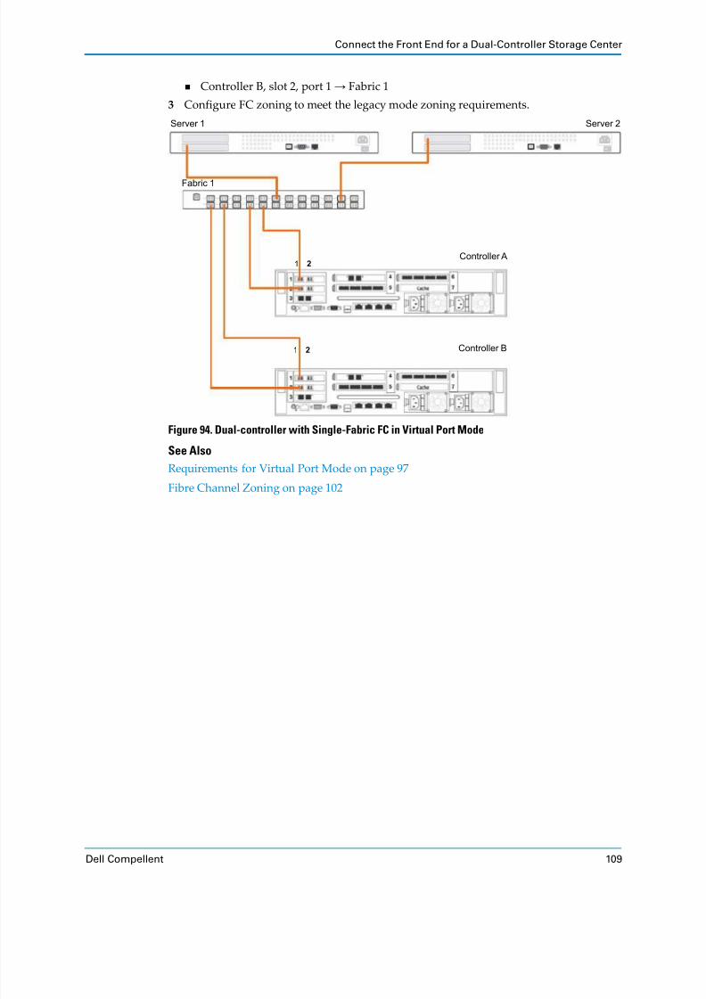
8/18/2019 Deployment Guide Sc8000
http://slidepdf.com/reader/full/deployment-guide-sc8000 119/218
Connect the Front End for a Dual-Controller Storage Center
Dell Compellent 109
Controller B, slot 2, port 1 → Fabric 1
3 Configure FC zoning to meet the legacy mode zoning requirements.
Figure 94. Dual-controller with Single-Fabric FC in Virtual Port Mode
See Also
Requirements for Virtual Port Mode on page 97
Fibre Channel Zoning on page 102
Controller B
Fabric 1
Server 1
Controller A
Server 2
1 2
1 2

8/18/2019 Deployment Guide Sc8000
http://slidepdf.com/reader/full/deployment-guide-sc8000 120/218
Chapter 4 Connect the Front End
110 Storage Center SC8000 Controller Deployment Guide
Virtual Port Mode with Dual-Fabric Fibre Channel
Use two fabrics with virtual port mode to prevent a FC switch failure or controller failure
from causing an outage.
In this configuration, there is one fault domain for each FC fabric. Each controller is
connected to both fabrics by two FC connections. If a single port fails, its virtual port fails over to another port in the same fault domain. If a controller fails, the virtual ports on the
failed controller move to ports on the other controller in the same fault domain.
Prerequisites
Each controller must have two available FC front‐end ports for each FC fabric.
The requirements for virtual port mode must be met.
Steps
1 Connect each server to both FC fabrics.
2 Connect fault domain 1 (shown in orange) to fabric 1.
Controller A, slot 1, port 1 → Fabric 1
Controller A, slot 2, port 1 → Fabric 1
Controller B, slot 1, port 1 → Fabric 1 Controller B, slot 2, port 1 → Fabric 1
3 Connect fault domain 2 (shown in blue) to fabric 2.
Controller A, slot 1, port 2 → Fabric 2
Controller A, slot 2, port 2 → Fabric 2
Controller B, slot 1, port 2 → Fabric 2
Controller B, slot 2, port 2 → Fabric 2
4 Configure FC zoning to meet the legacy mode zoning requirements.
Figure 95. Dual-controller with Dual-Fabric FC in Virtual Port Mode
Controller B
Fabric 1
Server 1
Controller A
Server 2
Fabric 2
1 2
1 2

8/18/2019 Deployment Guide Sc8000
http://slidepdf.com/reader/full/deployment-guide-sc8000 121/218
Connect the Front End for a Dual-Controller Storage Center
Dell Compellent 111
See Also
Requirements for Virtual Port Mode on page 97
Fibre Channel Zoning on page 102
Connect iSCSI Servers
Choose the iSCSI connectivity option that best suits the front‐end redundancy
requirements and network infrastructure.
Legacy Mode with Single‐Network iSCSI on page 111
Legacy Mode with Dual‐Network iSCSI on page 112
Virtual Port Mode with Single‐Network iSCSI on page 114
Virtual Port Mode with Dual‐Network iSCSI on page 115
Legacy Mode with Single-Network iSCSI
Connect legacy mode iSCSI to a single network if only one Ethernet switch is available and
you want to protect against controller failure.
In this
configuration,
two
fault
domains
are
spread
across
both
controllers.
Each
fault
domain contains sets of primary and reserve paths (P1‐R1 and P2‐R2). The reserved paths provide redundancy for single controller failure. This configuration is vulnerable to switch
failure.
Prerequisites
Each controller must have two available iSCSI front‐end ports.
Steps
1 Connect each iSCSI server to both Ethernet switches.2 Connect fault domain 1 (shown in orange) to switch 1.
Primary port P1: Controller A, slot 3, port 1 → Switch 1
Reserved port R1: Controller B, slot 3, port 1 → Switch 1
3 Connect fault domain 2 (shown in blue) to switch 1.
Primary port P2: Controller B, slot 4, port 2 → Switch 1
Reserved port R2: Controller A, slot 4, port 2 → Switch 1
Note: To prevent a port or cable failure from blocking access to volumes mapped to
a controller, connect two additional fault domains so that each controller has two
primary paths to the iSCSI network.

8/18/2019 Deployment Guide Sc8000
http://slidepdf.com/reader/full/deployment-guide-sc8000 122/218

8/18/2019 Deployment Guide Sc8000
http://slidepdf.com/reader/full/deployment-guide-sc8000 123/218
Connect the Front End for a Dual-Controller Storage Center
Dell Compellent 113
3 Connect fault domain 2 (shown in blue) to switch 1.
Primary port P2: Controller B, slot 4, port 2 → Switch 1
Reserved port R2: Controller A, slot 4, port 2 → Switch 1
4 Connect fault domain 3 (shown in green) to switch 2.
Primary port P3: Controller A, slot 4, port 1 → Switch 2
Reserved port
R3: Controller B, slot 4, port 1 → Switch 2
5 Connect fault domain 4 (shown in purple) to switch 2.
Primary port P4: Controller B, slot 3, port 2 → Switch 2
Reserved port R4: Controller A, slot 3, port 2 → Switch 2
Figure 97. Dual-controller with Dual-Network iSCSI in Legacy Mode
Ethernet Switch 1
iSCSI Network 1
Server
Ethernet Switch 2
iSCSI Network 2
Controller B
Controller A
R3 P4R4 P3P1 P2R1 R2
4 3 2 1
4 3 2 1
1 2
1 2
2 1
2 1

8/18/2019 Deployment Guide Sc8000
http://slidepdf.com/reader/full/deployment-guide-sc8000 124/218
Chapter 4 Connect the Front End
114 Storage Center SC8000 Controller Deployment Guide
Virtual Port Mode with Single-Network iSCSI
Connect virtual port mode iSCSI to a single network if only one Ethernet switch is available
and you want to protect against port or controller failure.
In this configuration, there is one fault domain because there is a single network. Each
controller is connected to the fabric by at least two iSCSI connections to provide port redundancy. If a single port fails, its virtual port fails over to another port. If a controller
fails, the virtual ports on the failed controller move to ports on the other controller. This
configuration is vulnerable to switch failure.
Prerequisites
Each controller must have two available iSCSI front‐end ports.
The requirements for virtual port mode must be met.
Steps
1 Connect each server to the iSCSI network.
2 Connect fault domain 1 (shown in orange) to iSCSI network 1.
Controller A, slot 3, port 1 → Switch 1
Controller B,
slot
3,
port
1 →
Switch 1
Controller B, slot 4, port 2 → Switch 1
Controller A, slot 4, port 2 → Switch 1
Figure 98. Dual-Controller with Single-Network iSCSI in Virtual Port Mode
Ethernet Switch 1
iSCSI Network 1
Server
Controller B
Controller A 4 3 2 1
4 3 2 1
1 2
1 2
2 1
2 1

8/18/2019 Deployment Guide Sc8000
http://slidepdf.com/reader/full/deployment-guide-sc8000 125/218
Connect the Front End for a Dual-Controller Storage Center
Dell Compellent 115
Virtual Port Mode with Dual-Network iSCSI
Use two networks with virtual port mode to prevent an Ethernet switch failure or controller failure from causing an outage.
In this configuration, there is one fault domain for each iSCSI network. Each controller is connected to both Ethernet networks by two iSCSI connections. If a single port fails, its
virtual port fails over to another port in the same fault domain. If a controller fails, the
virtual ports on the failed controller move to ports on the other controller in the same fault domain.
Prerequisites
Each controller must have two available iSCSI front‐end ports for each iSCSI network.
The requirements for virtual port mode must be met.
Steps
1 Connect each iSCSI server to both Ethernet switches.
2 Connect fault domain 1 (shown in orange) to iSCSI network 1.
Controller A, slot 3, port 1 → Switch 1
Controller B,
slot
3,
port
1 →
Switch 1
Controller B, slot 4, port 2 → Switch 1
Controller A, slot 4, port 2 → Switch 1
3 Connect fault domain 2 (shown in purple) to iSCSI network 2.
Controller A, slot 4, port 1 → Switch 2
Controller B, slot 4, port 1 → Switch 2
Controller B, slot 3, port 2 → Switch 2
Controller A, slot 3, port 2 → Switch 2

8/18/2019 Deployment Guide Sc8000
http://slidepdf.com/reader/full/deployment-guide-sc8000 126/218
Chapter 4 Connect the Front End
116 Storage Center SC8000 Controller Deployment Guide
Figure 99. Dual-Controller with Dual-Network iSCSI in Virtual Port Mode
Label the Front-End CablesLabel the front‐end cables to indicate which controller they are connected to, as well as the
controller slot and port. Pre‐made labels are shipped with SC8000 controllers.
1 Locate the pre‐made front‐end cables that shipped with the controller(s).
Figure 100. Front-End Cable Label
Ethernet Switch 1
iSCSI Network 1
Server
Ethernet Switch 2
iSCSI Network 2
Controller B
Controller A 4 3 2 1
4 3 2 1
1 2
1 2
2 1
2 1

8/18/2019 Deployment Guide Sc8000
http://slidepdf.com/reader/full/deployment-guide-sc8000 127/218
Label the Front-End Cables
Dell Compellent 117
2 Apply cable labels to both ends of each iSCSI cable that connects a controller to a front‐end switch.
a Prepare two labels by writing the controller number, slot, and port that the cable is
connected to.
b Near the connector, align the label perpendicular to the cable and affix it starting
with the top edge of the label.
Figure 101. Align Cable Label
c Wrap the label around the cable until it fully encircles the cable. The bottom of each
pre‐made label is clear so that it does not obscure the text.
Figure 102. Wrap Cable Label
d Apply a matching label to the other end of the cable.

8/18/2019 Deployment Guide Sc8000
http://slidepdf.com/reader/full/deployment-guide-sc8000 128/218
Chapter 4 Connect the Front End
118 Storage Center SC8000 Controller Deployment Guide
3 Apply cable labels to both ends of each FC cable that connects a controller a front‐end
fabric or server.
a Prepare two labels by writing the controller number, slot, and port that the cable is
connected to.
b Near the connector, align the dotted line on the label with the edge of the cable and
affix it starting with the top edge of the label.
Figure 103. Align Cable Label
c Wrap the label around the cable until it fully encircles the cable. The bottom of each
pre‐made label is clear so that it does not obscure the text.
Figure 104. Wrap Cable Label
d Apply a matching label to the other end of the cable.

8/18/2019 Deployment Guide Sc8000
http://slidepdf.com/reader/full/deployment-guide-sc8000 129/218
Dell Compellent 119
5 Set up the Storage Center Software
Connect the Storage Center management interfaces and configure the Storage Center
software.
ContentsPrerequisites . . . . . . . . . . . . . . . . . . . . . . . . . . . . . . . . . . . . . . . . . . . . . . . . . . . . . . . . . . . . . . . 119
Connect the Ethernet Management and iDRAC Interfaces . . . . . . . . . . . . . . . . . . . . . . . 121
Turn on the Hardware . . . . . . . . . . . . . . . . . . . . . . . . . . . . . . . . . . . . . . . . . . . . . . . . . . . . . . 124
Configure the Controller(s) . . . . . . . . . . . . . . . . . . . . . . . . . . . . . . . . . . . . . . . . . . . . . . . . . . 124
Verify Software Support for Enclosures . . . . . . . . . . . . . . . . . . . . . . . . . . . . . . . . . . . . . . . . 127
Start the Storage Center Startup Wizard . . . . . . . . . . . . . . . . . . . . . . . . . . . . . . . . . . . . . . . 128
Complete the Startup Wizard . . . . . . . . . . . . . . . . . . . . . . . . . . . . . . . . . . . . . . . . . . . . . . . . 129
Label SC200 and SC220 Enclosures . . . . . . . . . . . . . . . . . . . . . . . . . . . . . . . . . . . . . . . . . . . 163
PrerequisitesBefore the Storage Center software can be configured, the hardware must be connected,
and you
must
have
the
required
materials
and
documents.
Hardware ConfigurationAll hardware must be installed and cabled before beginning the software setup process. If server connectivity is through Fibre Channel (FC), the FC switches must be configured and
zoned before configureing the controller(s).

8/18/2019 Deployment Guide Sc8000
http://slidepdf.com/reader/full/deployment-guide-sc8000 130/218
Chapter 5 Set up the Storage Center Software
120 Storage Center SC8000 Controller Deployment Guide
Required MaterialsRemote connections to the Storage Center are required during different stages of configuration.
Make sure that you have the items listed in the following table.
Required DocumentsA Storage Architect or Business Partner designed the components of Storage Center for the
specific site. Pre‐installation documentation contains detailed information from the design
that is used during the setup process.
Pre‐installation documents include:
List of hardware needed to support storage requirements
Hardware Serial Number (HSN) and System Serial Number (SSN) used to configure the
controller(s)
Optional connectivity
diagrams
to
illustrate
cabling
between
the
controllers,
enclosures, switches, and servers
Optional network information, such as IP addresses, subnet masks, gateways
Refer to these documents for information about site‐specific settings used during controller configuration.
Required Software VersionsStorage Center hardware has minimum software version requirements.
Required Item Purpose
RS‐232 serial cable and PC or laptop
Used to run commands and view console messages during
controller configuration.
Computer connected to the
same network as the Storage
Center
Used to connect to the Storage Center System Manager (through a
web browser) to complete the Storage Center configuration.
Storage Center license file Used to activate purchased features.
License files use the naming convention snxxx_35_date.lic, where:
• sn xxx is the serial number of the Storage Center.
• 35 indicates that the system runs software higher than version 3.5.
• date shows the license generation date in YYMMDD format.
• .lic is the file extension.
Hardware Minimum Software Version
SC8000 (controller) 6.1.2
SC200/220 (enclosures) 6.2.1
SC280 (enclosures) 6.4.1

8/18/2019 Deployment Guide Sc8000
http://slidepdf.com/reader/full/deployment-guide-sc8000 131/218
Connect the Ethernet Management and iDRAC Interfaces
Dell Compellent 121
Connect the Ethernet Management and iDRAC InterfacesThe iDRAC and Ethernet management ports must be connected to a management network.
The ETH 0 port supports system login and access to the management software. It is also
used to send email, alerts, SNMP traps, and system data using Phone Home.
The iDRAC connection provides access to the controller for system information and
diagnostics.
Connect Single-Controller Management PortsConnect the controller Ethernet management and iDRAC ports to a management network.
1 Connect the 1 Gb ETH 0 (port 0) to an Ethernet switch.
2 Connect the iDRAC port to the Ethernet switch using a 1 Gb Ethernet cable.
Figure 105. Single Controller Management Connections
Switch (Corporate/Public Network)
Controller
1 Gb ETH 0 Port
iDRAC
31 20
IPC MGMT

8/18/2019 Deployment Guide Sc8000
http://slidepdf.com/reader/full/deployment-guide-sc8000 132/218
Chapter 5 Set up the Storage Center Software
122 Storage Center SC8000 Controller Deployment Guide
Connect Dual-Controller Management PortsConnect Ethernet management and iDRAC ports for both controllers to a management network.
1 Connect the 1 Gb ETH 0 (port 0) on each controller to an Ethernet switch or VLAN.
2 Connect the iDRAC port to the same Ethernet switch using a 1 Gb Ethernet cable.
Figure 106. Dual-Controller Management Connections
Label the Management CablesLabel the Ethernet management cables and iDRAC cables with the pre‐made labels that shipped with the controller(s).
1 Locate the Ethernet management and iDRAC labels that shipped with the controller(s).
Figure 107. Management Cable Label
Switch (Corporate/Public Network)
Controller A
Controller B
1 Gb ETH 0 Port
1 Gb ETH 0 PortiDRAC
iDRAC
31 20
IPC MGMT
31 20
IPC MGMT

8/18/2019 Deployment Guide Sc8000
http://slidepdf.com/reader/full/deployment-guide-sc8000 133/218
Connect the Ethernet Management and iDRAC Interfaces
Dell Compellent 123
2 Label both ends of each Ethernet cable with the appropriate management or iDRAC
label.
a Near the connector, align the label perpendicular to the cable and affix it starting
with the top edge of the label.
Figure 108. Align Cable Label
b Wrap the label around the cable until it fully encircles the cable. The bottom of each
pre‐made label is clear so that it does not obscure the text.
Figure 109. Wrap Cable Label
c Apply a matching label to the other end of the cable.

8/18/2019 Deployment Guide Sc8000
http://slidepdf.com/reader/full/deployment-guide-sc8000 134/218
Chapter 5 Set up the Storage Center Software
124 Storage Center SC8000 Controller Deployment Guide
Turn on the HardwareTurn on the enclosures first, and after the disks spin up, turn on the controllers.
1 Connect the enclosures and controller(s) to a power source.
2 Turn on each enclosure attached to the Storage Center.
a Simultaneously press both power switches on the rear of the enclosure to turn on the
enclosure.
b Repeat with each enclosure attached to the Storage Center, waiting for the disks to
spin up between enclosures.
3 Turn on each controller by pressing and holding the power button on the front of the
controller. The fans turn on as an indication that the controller is starting to come up.
Configure the Controller(s)Use a serial connection to the controller(s) to set the initial configuration.
Reset Hardware and System Serial NumbersConfigure the controller(s) with the HSN and SSN provided in the pre‐installation
documents.
1 Establish a serial connection to the controller.
a Use an RS‐232 serial cable to connect a PC or laptop to a Storage Center controller’s
RS‐232
serial
port.
(To
connect
from
a USB
port,
use
a USB
to
RS
‐232
converter.)
b Turn on the PC.
c Open a terminal emulator or a command‐line interface. Configure the connection as
shown in the following table.
Note: Make sure that all disks are up and spinning at full speed before turning
on any controllers.
Note: If configuring a dual‐controller Storage Center, perform this task for both
controllers. Use the lowest serial number for Controller 1.
Setting Value
Emulation VT220
Column Mode 132
Line Wrapping Off
Connection Serial Port
Connection Type Direct
Baud Rate 115,200
Parity None
Data Bits 8
Stop Bits 1
Flow Control Hardware or default
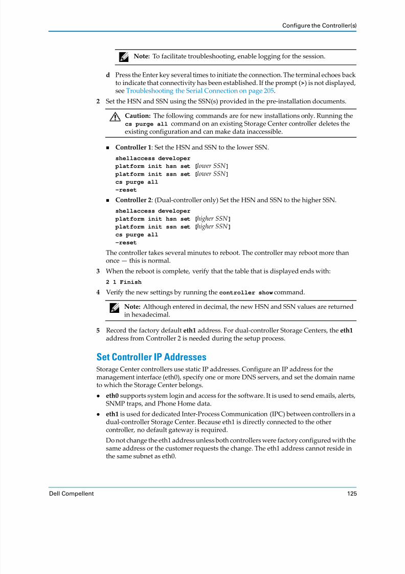
8/18/2019 Deployment Guide Sc8000
http://slidepdf.com/reader/full/deployment-guide-sc8000 135/218
Configure the Controller(s)
Dell Compellent 125
d Press the Enter key several times to initiate the connection. The terminal echoes back
to indicate that connectivity has been established. If the prompt (>) is not displayed, see Troubleshooting the Serial Connection on page 205.
2 Set the HSN and SSN using the SSN(s) provided in the pre‐installation documents.
Controller 1: Set the HSN and SSN to the lower SSN.
shellaccess developer
platform init hsn set [lower SSN ] platform init ssn set [lower SSN ]cs purge all
-reset
Controller 2:
(Dual
‐controller
only)
Set
the
HSN
and
SSN
to
the
higher
SSN.
shellaccess developer
platform init hsn set [higher SSN ] platform init ssn set [higher SSN ]cs purge all
-reset
The controller takes several minutes to reboot. The controller may reboot more than
once — this is normal.
3 When the reboot is complete, verify that the table that is displayed ends with:
2 1 Finish
4 Verify the new settings by running the controller show command.
5 Record the factory default eth1 address. For dual‐controller Storage Centers, the eth1
address from Controller 2 is needed during the setup process.
Set Controller IP AddressesStorage Center controllers use static IP addresses. Configure an IP address for the
management interface (eth0), specify one or more DNS servers, and set the domain name
to which the Storage Center belongs.
eth0 supports system login and access for the software. It is used to send emails, alerts,
SNMP traps, and Phone Home data.
eth1 is used for dedicated Inter‐Process Communication (IPC) between controllers in a
dual‐controller Storage Center. Because eth1 is directly connected to the other controller, no default gateway is required.
Do not change the eth1 address unless both controllers were factory configured with the
same address or the customer requests the change. The eth1 address cannot reside in
the same subnet as eth0.
Note: To facilitate troubleshooting, enable logging for the session.
Caution: The following commands are for new installations only. Running the
cs purge all command on an existing Storage Center controller deletes the
existing configuration and can make data inaccessible.
Note: Although entered in decimal, the new HSN and SSN values are returned
in hexadecimal.

8/18/2019 Deployment Guide Sc8000
http://slidepdf.com/reader/full/deployment-guide-sc8000 136/218
Chapter 5 Set up the Storage Center Software
126 Storage Center SC8000 Controller Deployment Guide
1 Run the following command to configure the management interface (etho).
controller ipconfig eth0 [IP address] [netmask ] [gateway ]
Example:controller ipconfig eth0 172.31.1.101 255.255.0.0 172.31.0.1
2 Run the following command to specify one or more DNS servers.
controller dnsserver [DNS server 1 IP address] [DNS server 2 IP address]
Example:
controller dnsserver 172.31.0.50 172.31.0.60
3 Run the following command to specify the domain to which the Storage Center belongs.
controller domainname [domain name]
Example:
controller domainname corp.dom
4 Verify the changes to the network settings by running the following command:controller show
Manage the iDRAC IP AddressThe SC8000 controller includes the Integrated Dell Remote Access Controller (iDRAC7) that is factory configured for Dynamic Host Configuration Protocol (DHCP). The iDRAC
can be left with the original configuration or it can be assigned a static IP address.
To see if the iDRAC is set to use a static IP address or DHCP, run the following
command:
platform bmc get source
To see what IP address is assigned to the iDRAC, run the following command:
platform bmc show
To set the iDRAC to a static IP address, run the following commands:
platform bmc set ip [IP address]
platform bmc set netmask [netmask ]
platform bmc set gateway [gateway]
Example:
platform bmc set ip 10.0.0.12
platform bmc set netmask 255.255.255.0
platform bmc set gateway 10.0.0.1
To set the iDRAC to use DHCP, run the following command:
platform bmc set source DHCP
Note that DHCP must be entered in all caps.
Note: If configuring a dual‐controller Storage Center, perform this task for both
controllers.
Note: To use the iDRAC in a non‐DHCP environment, a static IP address must be
set.
Note: On a dual‐controller Storage Center, change the iDRAC IP address on
both SC8000 controllers.

8/18/2019 Deployment Guide Sc8000
http://slidepdf.com/reader/full/deployment-guide-sc8000 137/218
Verify Software Support for Enclosures
Dell Compellent 127
Verify Software Support for EnclosuresIf the Storage Center has one or more SC200/220 or SC280 enclosures, use the command‐
line interface to verify that the controller is running the correct Storage Center OS version. If necessary, upgrade the controllers to a version that supports the enclosures.
1 At the command line, run the command controller show.
2 In the output of the command, find the three Version columns.
In the example above, the controller is running Storage Center OS 6.4.1.
3 If the controller is running a version older than the minimum version specified below, upgrade Storage Center OS to the minimum version or later.
a Use a web browser to connect to the management IP of the controller. The Storage
Center Startup Wizard appears.
b Accept the license agreement, then close the Startup Wizard.
c Update Storage Center OS to the latest version.
If the Storage Center has internet connectivity, use the System Manager to
download and install the latest Storage Center OS. For instructions, see the
Storage
Center
Software
Update
Guide.
If the Storage Center does not have internet connectivity, use the Storage Center Maintenance CD to perform the upgrade. See the Storage Center Maintenance
CD
Instructions document for details.
4 After updating the Storage Center OS, check for additional updates again. Enclosure
firmware updates may not install with the OS update, since Storage Center does not recognize some new hardware until after the OS is installed.
Check the Update Details window for Enclosure updates marked Deferrable, and
install them now. The enclosure firmware updates may take 20‐30 minutes. Do not interrupt the update after it has started.
5 If you are configuring a dual‐controller Storage Center, perform steps 1–4 on the second
controller. Firmware upgrades should have installed when the first controller was updated.
6 After both controllers are upgraded to the latest version, log out of System Manager and
log back in to continue with the setup process (see Step 3 on page 128).
Version Version Version
06 04 01
Enclosure Minimum Storage Center OS Version
SC200/220 6.2.1
SC280 6.4.1
Note: When using the network to upgrade Storage Center to OS 6.4.1 for an
SC280 enclosure, the enclosure firmware updates must be installed separately
after Storage Center OS 6.4.1 is installed.

8/18/2019 Deployment Guide Sc8000
http://slidepdf.com/reader/full/deployment-guide-sc8000 138/218
Chapter 5 Set up the Storage Center Software
128 Storage Center SC8000 Controller Deployment Guide
Start the Storage Center Startup WizardUse a web browser on a computer with network access to the Storage Center to access Storage Center System Manager and launch the Startup Wizard.
Prerequisites
You must have a computer that has connectivity to the Storage Center management
interface. The computer must have the following software installed:
One of the following supported web browsers (other browsers and versions may have
limited compatibility):
Microsoft Windows Internet Explorer Versions 7, 8, and 9
Microsoft Windows Internet Explorer 10 on the desktop (Internet Explorer 10
Modern version is not supported)
Mozilla Firefox on Microsoft Windows
The 32 bit (x86) Java Runtime Environment must be installed to run Storage Center
System Manager in any 32‐ bit browser.
Steps
1 Use a supported web browser to connect to the eth0 IP address or host name of controller 1.
2 Acknowledge any security messages.
The Storage Center Login page appears.
3 Enter the default user name and password:
User: Admin
Password: mmm
4 Click Login.
Note: Messages that appear may differ depending on the browser used. (Click
Continue to this website in Internet Explorer or add a security exception in
Firefox.)
Note: The user name and password are case‐sensitive.

8/18/2019 Deployment Guide Sc8000
http://slidepdf.com/reader/full/deployment-guide-sc8000 139/218

8/18/2019 Deployment Guide Sc8000
http://slidepdf.com/reader/full/deployment-guide-sc8000 140/218
Chapter 5 Set up the Storage Center Software
130 Storage Center SC8000 Controller Deployment Guide
Load the License FileUse the Load License page to upload the Storage Center license file. The license file makes settings available depending on what features were purchased.
1 Browse to the location of the license file.
2 Verify that the serial number of the license file matches the serial number of the
controller by
comparing
the
name
of
the
license
file
to
the
title
bar
of
the
Startup
Wizard.
License files use the naming convention snxxx_35_date.lic, where:
sn xxx is the serial number of the Storage Center.
35 indicates that the system runs software higher than version 3.5.
date shows the license generation date in YYMMDD format.
.lic is the file extension.
3 Select the license file, then click Load License. The Startup Wizard displays a message
when the license is successfully loaded.
If the license loads successfully, the message The license submission has completed
successfully appears.
If the message Error: The license file is not valid message is displayed, see
Troubleshooting Licenses on page 206.
4 Click Continue.
If standard drives are detected, the Create Disk Folder page appears.
If Self
‐Encrypting
Drives
(SEDs)
that
are
Federal
Information
Processing
Standard
(FIPS) 140‐2 certified are detected, Storage Center formats the drives as if Secure
Data will be used, and you are asked whether to create a Secure Data folder. See
About Secure Data on page 131.
If the No disks could be found message is displayed, see Troubleshooting Enclosures on page 205.

8/18/2019 Deployment Guide Sc8000
http://slidepdf.com/reader/full/deployment-guide-sc8000 141/218
Complete the Startup Wizard
Dell Compellent 131
About Secure Data
Secure Data is a licensed feature that provides data‐at‐rest encryption with key
management. Using Secure Data to manage SEDs requires an external key management server. If a key management server has not been configured or is unavailable, you can
manage FIPS SEDs into a Secure Data folder, however the disks remain in a pending state
until the key management server is available.
Each FIPS disk in Storage Center has an internal Media Encryption Key (MEK). The key
resides on the disk, providing encryption for data written to the disk and decryption for data as it is read from the disk. Destroying the key makes any data on the disk immediately
and permanently unreadable, a process referred to as a crypto erase. When you add an SED
to, or release an SED from a Secure Data folder, the MEK is destroyed and a new key is generated. This allows the disk to be reused, although all previous data is lost.
To protect data at rest, all SEDs in a Secure Data disk folder lock when power is removed
(Lock on Reset enabled). When power is removed from the drive, the drive cannot be
unlocked
without
access
to
the
authority
credential
stored
in
the
key
management
server.
Note: Because disks that contain user data cannot be moved from a Secure Data
folder, Storage Center does not crypto erase disks that contain user data.

8/18/2019 Deployment Guide Sc8000
http://slidepdf.com/reader/full/deployment-guide-sc8000 142/218
Chapter 5 Set up the Storage Center Software
132 Storage Center SC8000 Controller Deployment Guide
Create a Disk FolderUse the Create Disk Folder pages to assign disks to a folder in order to create a single pool of storage for volumes.
1 Select disks for the disk folder. By default, the Startup Wizard selects all available
disks.
a Scroll through the list looking at the Enclosure column and the Position or Name
column to verify that all the expected enclosures and disks are listed.
If enclosures or disks are missing, the issues might be fixed by following
Troubleshooting Enclosures on page 205.
b (Optional) From the list of disks, select disks to include in the disk folder. By default, all disks are selected.
To exclude individual disks from the disk folder, clear the corresponding check
boxes.
To include individual disks in the disk folder, click Unselect All and then select the individual disks to include.
To select all disks, click Select All.
c Click Continue. The Startup Wizard displays a prompt to select disks to designate
as hot spares.
Note: A Secure Data folder can only contain self‐encrypting FIPS drives, which
are indicated by a yellow lock icon.
Note: Dell Compellent recommends selecting all available disks to maximize
the benefits of Data Progression.

8/18/2019 Deployment Guide Sc8000
http://slidepdf.com/reader/full/deployment-guide-sc8000 143/218
Complete the Startup Wizard
Dell Compellent 133
2 Review the hot spare disks automatically selected by the Startup Wizard.
A hot spare disk is held in reserve until a disk fails, at which point the hot spare replaces the failed disk. The hot spare disk must be as large or larger than the largest disk of its
type in the disk folder. For redundancy, there must be at least one hot spare for each
enclosure.
In general, System Manager uses the following best practices in designating hot spares:
For 2U enclosures, one spare disk for every disk class (10K, 7.5K, and so on).
For 5U enclosures, one spare disk for every 21 disks, however no single row will contain more than one spare disk.
a (Optional) Change the selection by selecting or clearing disks to be used as hot spares.
b Click Continue , and if prompted, click OK to confirm. The Startup Wizard displays a summary of the disk folder that will be created.

8/18/2019 Deployment Guide Sc8000
http://slidepdf.com/reader/full/deployment-guide-sc8000 144/218

8/18/2019 Deployment Guide Sc8000
http://slidepdf.com/reader/full/deployment-guide-sc8000 145/218
Complete the Startup Wizard
Dell Compellent 135
b Configure the Tier Redundancy for each tier.
The redundancy level for each tier defaults to either single redundant or dual redundant depending upon the disks expected to be found in the tier. If a tier contains at least six managed disks of which one is 900 GB or greater, then that tier and all tiers below it are set to dual redundant storage by default. If a tier contains at least six managed disks of 1.8 TB or greater, then that tier and all tiers below it are
set to
dual
redundant
storage
and
cannot
be
changed.
Single redundant storage protects against the loss of any one drive.
RAID 10 (each disk is mirrored)
RAID 5‐5 (4 data segments/1 parity segment per stripe)
RAID 5‐9 (8 data segments/1 parity segment per stripe)
Dual redundant storage protects against the loss of any two drives:
RAID 10 Dual Mirror (data is written simultaneously to three separate disks)
RAID 6‐6 (4 data segments/2 parity segments per stripe)
RAID 6‐10 (8 data segments/2 parity segments per stripe)
c From the Datapage Size drop‐down menu, choose a datapage size.
2 MB: (Default) Recommended for most application needs.
512 KB: Appropriate for applications with high performance needs (such as
certain databases) or environments in which Replays are taken frequently under heavy IO. Selecting this size reduces the amount of space the System Manager can present to servers.
4 MB: Appropriate for systems that use a large amount of disk space with
infrequent Replays (such as video streaming).
d To configure the disk folder to use RAID 0, select the Prepare for Non‐Redundant Storage check box. Non‐redundant storage does not protect data in the event of a
disk failure. Select this option only for data that is backed up some other way.
e Click Continue. The disk folder summary appears.
5 Click Create Now , and if prompted, click OK to confirm. The Add Controller page
appears.
Caution: When considering using either the 512 KB or 4 MB datapage
settings, it is recommended that you contact Dell Technical Support Services for advice on balancing resources and to understand the impact on
performance.

8/18/2019 Deployment Guide Sc8000
http://slidepdf.com/reader/full/deployment-guide-sc8000 146/218
Chapter 5 Set up the Storage Center Software
136 Storage Center SC8000 Controller Deployment Guide
Add a ControllerUse the Add Controller pages to configure the second controller and to enter the IPv6
address, if used, on the leader controller.
1 Proceed based on the number of controllers in the Storage Center.
Single‐controller Storage Center: Click Continue Setup. The Time Settings page
appears.
Dual‐controller Storage Center: Click Add Controller. The wizard prompts you to
enter IPv6 address information for the first (Leader) controller.

8/18/2019 Deployment Guide Sc8000
http://slidepdf.com/reader/full/deployment-guide-sc8000 147/218
Complete the Startup Wizard
Dell Compellent 137
2 Proceed based on whether you use IPv6 for controller addressing.
a If IPv6 is used, enter IPv6 information for the first controller and click Continue.
b If IPv6 is not used, click Skip IPv6 Configuration.
3 Configure the following fields:
Controller ID: If the HSN for Controller 2 is included in the license file, the add
controller process uses that value as the Controller ID and a different value cannot
be
entered.
If
the
HSN
for
Controller
2
is
not
in
the
license
file,
enter
the
HSN
value.
The dimmed box in the preceding figure indicates that the HSN was in the license
file making the Controller ID box unavailable.
Ether 0 Interface: Enter the IP Address , Net Mask , and Gateway for the Ether 0
interface on Controller 2.
Ether 1 Interface: Enter the IP Address , Net Mask , and Gateway for the Ether 1
interface. Use the IP address from the controller show console command for Controller 2. (Used for communication between controllers.)
Primary DNS Server: Enter the IP address of the primary DNS server.
Secondary DNS Server: (Optional) Enter the IP address of a secondary DNS server.
Domain Name: (Optional) Enter the domain name for the controller.
4 Click Continue.
The Startup Wizard displays a message that data and configuration information on the
second controller is lost and asks for confirmation.
Note: Information displayed in the following figure is for illustration only. The values displayed are unique to each Storage Center.

8/18/2019 Deployment Guide Sc8000
http://slidepdf.com/reader/full/deployment-guide-sc8000 148/218
Chapter 5 Set up the Storage Center Software
138 Storage Center SC8000 Controller Deployment Guide
5 Click Join Now. Wait for the process to complete and for the controller to reboot, which
can take a few minutes. When complete, the Time Settings page appears.
Set the TimeUse the Time Settings page is to set the system time for the Storage Center.
1 Set the time zone.
a From the Region drop‐down menu, select the geographical region in which the
Storage Center is located.
b From the Time Zone drop‐down menu, select the time zone in which the Storage
Center is located.

8/18/2019 Deployment Guide Sc8000
http://slidepdf.com/reader/full/deployment-guide-sc8000 149/218
Complete the Startup Wizard
Dell Compellent 139
2 Set the system time using one of the following methods.
To configure
time
manually,
select
Configure
Time
Manually , then
enter
the
date
and time.
To configure time using a Network Time Protocol (NTP) server, select Use NTP
Time Server , then enter the fully qualified domain name (FQDN) or IP address of an NTP server.
3 When the system time has been set, click Continue. The System Setup page appears.
Set the System IP AddressUse the System Setup page the system name and management IP address for the entire
Storage Center (one or more controllers and one or more enclosures).
1 In the System Name field, enter a name for the Storage Center. This is typically the
serial number of Controller 1.
2 (Dual‐controller only) In the Management IP Address field, enter the management IP
address specified in the pre‐installation documents. (On single‐controller systems, this field is not displayed and the message at the top of the pane reads simply, Set the
System’s name.)
The management IP address is distinct from the controller 1 and controller 2 addresses. It is the address that manages a dual‐controller Storage Center as a whole. If either controller fails, the management IP address remains valid.
Note: For locations in the United States, either select US as the region and select a time zone name, or select America as the region and select a city within the
same time zone.
Note: Accurate time synchronization is critical for replications. Dell Compellent recommends using NTP to set the system time. For more information, see:support.ntp.org/bin/view/Support/WebHome .

8/18/2019 Deployment Guide Sc8000
http://slidepdf.com/reader/full/deployment-guide-sc8000 150/218
Chapter 5 Set up the Storage Center Software
140 Storage Center SC8000 Controller Deployment Guide
3 Click Continue. The wizard prompts you to enable or disable the read and write cache.
4 Select or clear the check boxes to enable or disable read and write cache.
5 Click Continue.
If a Secure Data folder is used with FIPS SEDs, you are prompted to configure a key
management server.
if standard drives are used, the Configure SMTP page appears.
Note: Disable cache only if no volumes will ever use cache. If cache is left enabled on this page, it can be disabled later for individual volumes. See the
Storage
Center
System
Manager
Administrator’s
Guide for information on disabling
cache on a volume‐ by‐volume basis.

8/18/2019 Deployment Guide Sc8000
http://slidepdf.com/reader/full/deployment-guide-sc8000 151/218
Complete the Startup Wizard
Dell Compellent 141
Configure a Key Management ServerUsing Secure Data to manage Self‐Encrypting Drives (SEDs) requires an external key
management server. Establish a connection to an existing key management server in this step.
1 Enter the Host name or IP address of the key management server, the port number to
use, and a communication timeout value.
2 (Optional) Enter the name of the host or hosts to use if the primary host is unavailable.
3 If the key management server is configured to validate the client certificate, enter the
key management credentials in the Client Username and Client Password boxes.
4 Click Continue. The next page of the wizard provides information about the SSL
certificate files required to communicate with the key management server. The next page of the wizard provides information about the SSL certificate files required to
communicate with the key management server. The certificate files are generated by
your system administrator; they are not supplied by Dell Compellent.
5 Click Upload Client Certs.
6 Navigate to and select the existing public key (*.pem) file.
7 Click Continue.
8 Repeat Step 5 through Step 7 for the second controller (if present).
9 Click Upload Certstore Cert.
10 Navigate to and select the existing public key (*.pem) file.
11 Click Continue. The last page of the wizard appears.
12 Click Finish Now. The Configure SMTP page appears.
Note: The key management server must be available to manage new self‐
encrypting FIPS disks into a Secure Data folder that has already been in the Secure state.

8/18/2019 Deployment Guide Sc8000
http://slidepdf.com/reader/full/deployment-guide-sc8000 152/218
Chapter 5 Set up the Storage Center Software
142 Storage Center SC8000 Controller Deployment Guide
Configure SMTPUse the Configure SMTP page to configure the SMTP mail server and the sender email address. This configuration enables alert message emails to be sent to users who have
specified a recipient address in their contact properties.
1 In the SMTP Mail Server field, enter the IP address or fully qualified domain name of the SMTP email server. Click Test server to verify connectivity to the SMTP server.
2 In the Sender E‐mail Address field, enter the email address of the sender. This address is required by most SMTP servers and is used as the MAIL FROM address of email messages.
Note: To configure SMTP later, click Skip SMTP Configuration. SMTP settings can
be configured later in the System Manager through the Storage Management
menu.

8/18/2019 Deployment Guide Sc8000
http://slidepdf.com/reader/full/deployment-guide-sc8000 153/218
Complete the Startup Wizard
Dell Compellent 143
3 (Optional) Click Advanced to configure additional SMTP settings for sites that use an
advanced SMTP configuration. The page for advanced options appears.
a Verify that the Enable SMTP E‐mail check box is selected.
b In the SMTP Mail Server field, verify the IP address or fully qualified domain name
of the SMTP mail server that you entered in Step 1 on page 142. Modify this field if necessary.
c In the Backup SMTP Mail Server field, enter the IP address or fully qualified
domain name of the backup SMTP mail server.
d Click Test server to test the connection(s).
e In the Sender E‐mail Address (MAIL FROM) field, verify the email address of the
sender that you entered in Step 2 on page 142. Modify this field if necessary.
f In the Common Subject Line field, enter a common subject line for all emails from
Storage Center.
g (Optional) Select Send Extended Hello (EHLO) to configure use of extended hello
for mail system compatibility.
Instead of beginning the session with the HELO command, the receiving host issues the HELO command. If the sending host accepts this command, the receiving host then sends it a list of SMTP extensions it understands, and the sending host then
knows which SMTP extensions it can use to communicate with the receiving host. Implementing Extended SMTP (ESMTP) requires no modification of the SMTP
configuration for either the client or the mail server.
h (Optional) Select
Use
Authorized
Login
(AUTH
LOGIN) and
enter
the
Login
ID
and Password if the email system requires the use of an authorized login.
4 Click Continue. The Update Setup page appears.
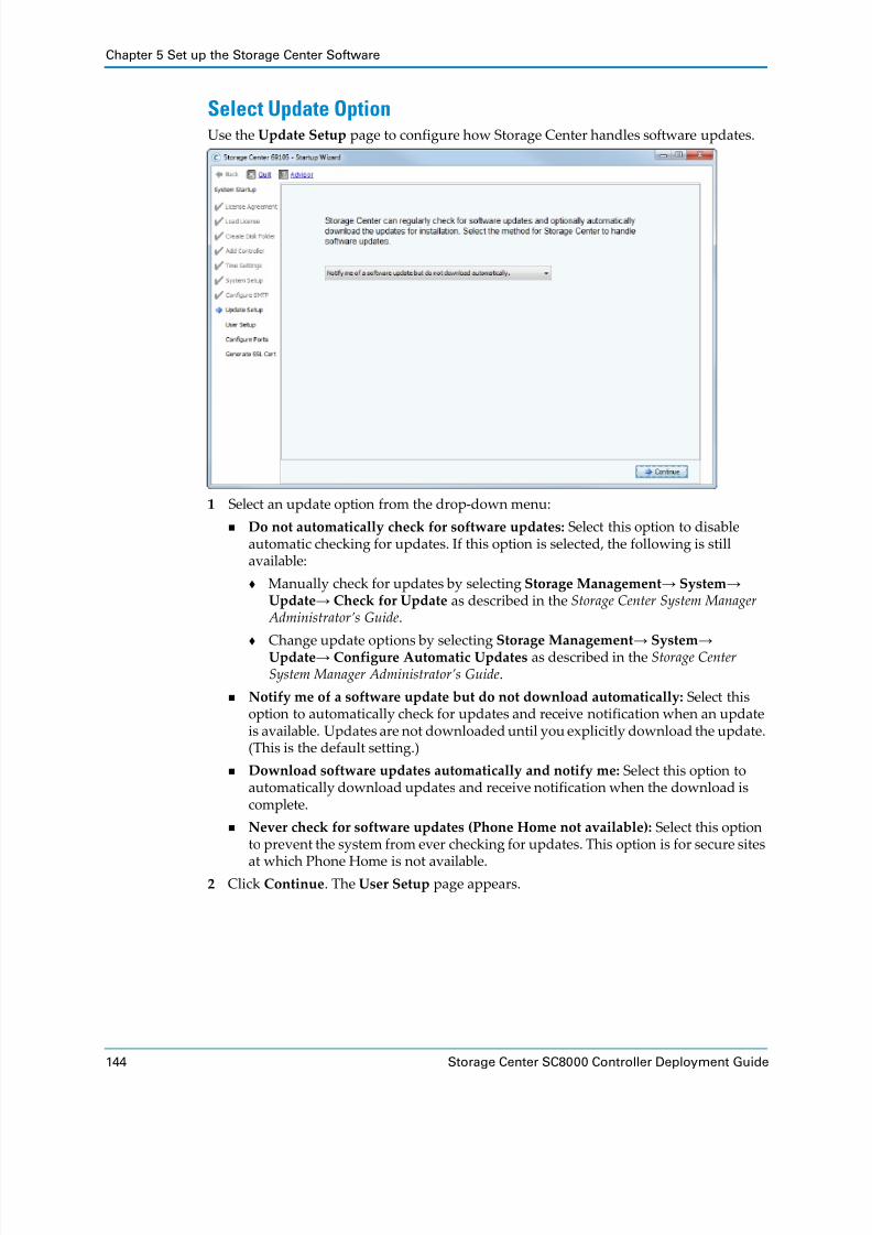
8/18/2019 Deployment Guide Sc8000
http://slidepdf.com/reader/full/deployment-guide-sc8000 154/218
Chapter 5 Set up the Storage Center Software
144 Storage Center SC8000 Controller Deployment Guide
Select Update OptionUse the Update Setup page to configure how Storage Center handles software updates.
1 Select an update option from the drop‐down menu:
Do not automatically check for software updates: Select this option to disable
automatic checking for updates. If this option is selected, the following is still available:
Manually check for updates by selecting Storage Management→ System→
Update→ Check for Update as described in the Storage Center System
Manager
Administrator’s
Guide.
Change update options by selecting Storage Management→ System→
Update→ Configure Automatic Updates as described in the Storage
Center
System
Manager
Administrator’s
Guide.
Notify me of a software update but do not download automatically: Select this option to automatically check for updates and receive notification when an update
is available. Updates are not downloaded until you explicitly download the update. (This is the default setting.)
Download software updates automatically and notify me: Select this option to
automatically download updates and receive notification when the download is
complete.
Never check for software updates (Phone Home not available): Select this option
to prevent the system from ever checking for updates. This option is for secure sites
at which
Phone
Home
is
not
available.
2 Click Continue. The User Setup page appears.

8/18/2019 Deployment Guide Sc8000
http://slidepdf.com/reader/full/deployment-guide-sc8000 155/218
Complete the Startup Wizard
Dell Compellent 145
Set Admin AccountUse the User Setup page to the session timeout and email addresses for the Admin
account.
3 From the Session Timeout drop‐down list, select the session timeout.
4 In the Email, Email 2, and Email 3 fields, enter email addresses to which the Storage
Center sends system alerts.
5 (Optional) Click Send test e‐mail to make sure that the email addresses are accurate.
6 Click Continue.
If the Storage Center has iSCSI IO cards, the Configure IO Cards page appears.
If there are no iSCSI IO cards, the Configure Ports page appears.
Note: Make sure that the administrator receives the test email(s). Storage Center
uses email to send system alerts.

8/18/2019 Deployment Guide Sc8000
http://slidepdf.com/reader/full/deployment-guide-sc8000 156/218
Chapter 5 Set up the Storage Center Software
146 Storage Center SC8000 Controller Deployment Guide
Configure IO CardsThe Configure IO Cards page appears if the Storage Center detects iSCSI IO cards. Use this
page to configure network settings for iSCSI IO cards.
1 (Optional) Click Skip iSCSI IO Card Configuration to configure network settings for the iSCSI IO cards later. The Configure Ports page appears.
2 For each iSCSI IO card that is used, complete the IP Address , a Subnet Mask , and
Gateway fields. Uninitialized iSCSI IO cards have an IP Address of 0.0.0.0 and will be
listed on a warnings page in the next step.
3 When you are finished, click Continue.
If no messages are generated, iSCSI IO card configuration is saved and the
Configure Ports page appears.
If there are issues, a message appears.
Click No
to
go
back
and
correct
the
IP
Address ,
Subnet
Mask ,
and/or
Gateway
address for cards that generated errors and/or warnings.
Click Yes to ignore the message and continue. The Configure Ports page appears.
Note: Dell Compellent recommends that you configure iSCSI IO cards during
setup.

8/18/2019 Deployment Guide Sc8000
http://slidepdf.com/reader/full/deployment-guide-sc8000 157/218
Complete the Startup Wizard
Dell Compellent 147
Configure PortsUse the Configure Ports page to configure the front‐end and back‐end ports.
Select the Front-End Connectivity Mode(s)
Select the front‐end connectivity mode for each transport type (FC and/or iSCSI). If virtual
port mode
is
licensed,
the
transport
types
can
be
configured
to
use
different
modes.
If
virtual port mode is not licensed, all transport types must use legacy mode.
Configure Ports When Virtual Port Mode Is Not Licensed
If Virtual Ports is not licensed, the wizard informs you that the local ports have not been
configured.
1 Click Continue to generate the initial port configuration.
While the initial port configuration is being generated, the Startup Wizard displays a
page showing progress. After the configuration has been generated, it is automatically
validated.
If … Then …
Virtual Ports is Not Licensed All transport types use Legacy Mode. In this case, the Startup
Wizard displays the Initial Port Configuration page. To
continue, go to Configure Ports When Virtual Port Mode Is Not Licensed on page 147.
Virtual Ports is Licensed FC and iSCSI transport types can use legacy mode or virtual port mode. In this case, the Startup Wizard displays an operational mode choice page that allows for the choice between modes for each supported transport type. To continue, go to Configure
Ports When Virtual Port Mode Is Licensed on page 149.
Note: To skip port initialization or if there is no FC switch set up, click Skip Port Initialization.

8/18/2019 Deployment Guide Sc8000
http://slidepdf.com/reader/full/deployment-guide-sc8000 158/218
Chapter 5 Set up the Storage Center Software
148 Storage Center SC8000 Controller Deployment Guide
If the validation is successful, a confirmation page appears stating that the port configuration has been generated.
If the validation fails, a page displaying warnings appears.
2 Click Configure Local Ports. The wizard displays a tab for each type of IO card that is
installed in the Storage Center (FC, iSCSI, and SAS).
3 Configure the Purpose , Fault Domain , and User Alias for all transport types. See
Configure Local Ports on page 154.
4 When you are finished configuring the local ports, click Assign Now. The wizard
informs you that the port configuration has been generated.

8/18/2019 Deployment Guide Sc8000
http://slidepdf.com/reader/full/deployment-guide-sc8000 159/218
Complete the Startup Wizard
Dell Compellent 149
5 Click Continue. The Generate SSL Cert page appears.
Configure Ports When Virtual Port Mode Is Licensed
If Virtual Ports is licensed, the wizard informs prompts you to choose the front‐end
connectivity mode(s) for the available transport types (FC and/or iSCSI).
1 Select the front‐end connectivity mode(s).
a Select the operational mode for FC and iSCSI transports.
b Click Continue to configure the selected operational mode(s). The wizard informs you that the operational modes have been configured.

8/18/2019 Deployment Guide Sc8000
http://slidepdf.com/reader/full/deployment-guide-sc8000 160/218
Chapter 5 Set up the Storage Center Software
150 Storage Center SC8000 Controller Deployment Guide
c Click Continue to begin port initialization in the selected operational mode(s).
The wizard verifies the configuration, converts selected transports to the selected
mode, displays progress pages, and presents a confirmation page when operational modes for transport types have been configured and initialized.

8/18/2019 Deployment Guide Sc8000
http://slidepdf.com/reader/full/deployment-guide-sc8000 161/218
Complete the Startup Wizard
Dell Compellent 151
d Click Continue. The page that appears next depends on whether there are any iSCSI transports in virtual port mode:
iSCSI in virtual port mode: A request is displayed to provide the IP address information required to create the default iSCSI Fault Domain. Go to Step 2 on
page 151.
iSCSI in legacy port mode (or no iSCSI ports): While the initial port
configuration is being generated, the Startup Wizard displays a page showing
progress. After the configuration has been generated, it is automatically
validated. If the validation is successful, the confirmation page appears. If there
are issues, a page appears listing error messages. Go to Step 3 on page 152.
2 (iSCSI virtual port mode only) Configure the control port for the iSCSI fault domain.
a Enter the IP address, netmask, gateway, and port for the control port for the new
iSCSI fault domain. Check the pre‐installation documentation for this address.
b Click Continue.
The Startup Wizard generates the new iSCSI fault domain and the initial port configuration. While the initial port configuration is being generated, the Startup
Wizard displays a page showing progress. After the configuration has been
generated, it is automatically validated.
If there are issues, an error message page appears.
If the validation is successful, a confirmation page appears.

8/18/2019 Deployment Guide Sc8000
http://slidepdf.com/reader/full/deployment-guide-sc8000 162/218
Chapter 5 Set up the Storage Center Software
152 Storage Center SC8000 Controller Deployment Guide
3 Click Configure Local Ports. The wizard displays a tab for each type of IO card that is
installed in the Storage Center (FC, iSCSI, and SAS).
4 Configure the Purpose , Fault Domain , and User Alias for all transport types. See
Configure Local
Ports
on
page 154.
5 When you are finished configuring the local ports, click Assign Now. The wizard
informs you that the port configuration has been generated.

8/18/2019 Deployment Guide Sc8000
http://slidepdf.com/reader/full/deployment-guide-sc8000 163/218
Complete the Startup Wizard
Dell Compellent 153
6 Click Continue. The Generate SSL Cert page appears.

8/18/2019 Deployment Guide Sc8000
http://slidepdf.com/reader/full/deployment-guide-sc8000 164/218
Chapter 5 Set up the Storage Center Software
154 Storage Center SC8000 Controller Deployment Guide
Configure Local Ports
Configure the Purpose , Fault Domain , and User Alias for all transport types. Valid port purposes for transport types depend on whether virtual ports mode is licensed on Storage
Center.
Configure FC Ports — Legacy Mode on page 154
Configure FC
Ports
—
Virtual
Port
Mode
on
page 156
Configure iSCSI Ports — Legacy Mode on page 157
Configure iSCSI Ports — Virtual Port Mode on page 158
Configure SAS Ports on page 159
The following table shows the port purposes for each transport type.
Configure FC Ports — Legacy Mode
Use the FC tab to configure the Fibre Channel ports in legacy mode.1 Click the FC tab.
Port Purpose Transport Type Description
Legacy Mode
Unknown FC, iSCSI, and SAS One of the following:
• Port purpose is not yet defined.
• The port
is
unused.
• (SAS and FC only) The port is used for direct‐connect inter‐process communication (IPC).
Front‐End Primary FC and iSCSI Port is connected to servers and is used for the server IO path.
Front‐End Reserved FC and iSCSI Port is connected to servers and used as a failover path. Only used for dual‐controller Storage Centers.
Back End FC and SAS Port is connected to disk enclosures.
Direct Connect FC and iSCSI This port purpose is not used. Do not select it for any
ports.
Virtual Port Mode
Unknown FC, iSCSI, and SAS One of the following:
• Port purpose is not yet defined.
• The port is unused.
• (SAS and FC only) The port is used for direct‐connect inter‐process communication (IPC).
Front End FC and iSCSI Port is connected to servers and is used for the server IO path.
Back End FC Port is connected to disk enclosures.

8/18/2019 Deployment Guide Sc8000
http://slidepdf.com/reader/full/deployment-guide-sc8000 165/218
Complete the Startup Wizard
Dell Compellent 155
2 Create the required fault domains. For a dual‐controller Storage Center, create a fault domain for each pair of redundant FC ports. For a single‐controller Storage Center, create a single fault domain for all FC ports.
a Click Edit Fault Domains. The wizard displays a list of the currently defined fault domains.
b Click Create Fault Domain. A dialog box appears.
c In the Name field, type a name for the fault domain.
d From the Type drop‐down menu, select FC.
e (Optional) In the Notes field, type a description of the fault domain.
f Click Continue.
The
dialog
box
displays
a summary.
g Click Create Now to create the fault domain.
h Repeat steps b–g as needed to create additional fault domains.
i When you are finished creating fault domains, click Return. The FC tab appears.
3 Configure each back‐end FC port.
a Set the Purpose field to Back End.
b Confirm that the Fault Domain field is set to <none>.
c (Optional) Type a descriptive name in the User Alias field.
4 Configure each front‐end FC port.
a Set the Purpose field to Front End Primary or Front End Reserved as appropriate.
b Set the Fault Domain field to the appropriate fault domain that you created.
c (Optional) Type a descriptive name in the User Alias field.
5 Configure each port that is unused or used for IPC between controllers.
a Set the Purpose field to Unknown.
b Confirm that the Fault Domain field is set to <none>.
c (Optional) Type a descriptive name in the User Alias field.

8/18/2019 Deployment Guide Sc8000
http://slidepdf.com/reader/full/deployment-guide-sc8000 166/218
Chapter 5 Set up the Storage Center Software
156 Storage Center SC8000 Controller Deployment Guide
Configure FC Ports — Virtual Port Mode
Use the FC tab to configure the Fibre Channel ports in virtual port mode.
1 Click the FC tab.
2 Create a fault domain for each FC fabric.
a Click Edit Fault Domains. The wizard displays a list of the currently defined fault domains.
b Click Create Fault Domain. A dialog box appears.
c In the Name field, type a name for the fault domain.
d From the Type drop‐down menu, select FC.
e (Optional) In the Notes field, type a description of the fault domain.
f Click Continue. The dialog box displays a summary.
g Click Create Now to create the fault domain.
h Repeat steps b–g as needed to create additional fault domains.
i When you are finished creating fault domains, click Return. The FC tab appears.
3 Configure each back‐end FC port.
a Set the Purpose field to Back End.
b Confirm that the Fault Domain field is set to <none>.
c (Optional) Type a descriptive name in the User Alias field.
4 Configure each front‐end FC port.
a Set the Purpose field to Front End.
b Set the Fault Domain field to the appropriate fault domain that you created.
c (Optional) Type a descriptive name in the User Alias field.
5 (Optional) Change the preferred physical port for one or more virtual ports.
a Click Edit Virtual Ports. The wizard displays a list of virtual ports.
b For each virtual port that you want to modify, select the preferred physical port In
the Preferred Physical Port.

8/18/2019 Deployment Guide Sc8000
http://slidepdf.com/reader/full/deployment-guide-sc8000 167/218
Complete the Startup Wizard
Dell Compellent 157
c When you are finished, click Apply Changes. The iSCSI tab appears.
6 Configure each port that is unused or used for IPC between controllers.
a Set the Purpose field to Unknown.
b Confirm that the Fault Domain field is set to <none>.
c (Optional) Type a descriptive name in the User Alias field.
Configure iSCSI Ports — Legacy Mode
Use the iSCSI tab to configure the iSCSI ports in legacy mode.
1 Click the iSCSI tab.
2 Create the
required
fault
domains.
For
a dual
‐controller
Storage
Center,
create
a fault
domain for each pair of redundant iSCSI ports. For a single‐controller Storage Center, create a single fault domain for all iSCSI ports.
a Click Edit Fault Domains. The wizard displays a list of the currently defined fault domains.
b Click Create Fault Domain. A dialog box appears.
c In the Name field, type a name for the fault domain.
d From the Type drop‐down menu, select iSCSI.
e (Optional) In the Notes field, type a description of the fault domain.
f Click Continue. The dialog box displays a summary.
g Click Create Now to create the fault domain.
h Repeat steps b–g as needed to create additional fault domains.
i When you are finished creating fault domains, click Return. The iSCSI tab appears.
3 Configure each front‐end iSCSI port.
a Set the Purpose field to Front End Primary or Front End Reserved as appropriate.
b Set the Fault Domain field to the appropriate fault domain that you created.
c (Optional) Type a descriptive name in the User Alias field.

8/18/2019 Deployment Guide Sc8000
http://slidepdf.com/reader/full/deployment-guide-sc8000 168/218
Chapter 5 Set up the Storage Center Software
158 Storage Center SC8000 Controller Deployment Guide
4 Confirm that unused ports are not configured.
a Set the Purpose field to Unknown.
b Confirm that the Fault Domain field is set to <none>.
c (Optional) Type a descriptive name in the User Alias field.
Configure iSCSI Ports — Virtual Port Mode Use the iSCSI tab to configure the iSCSI ports in virtual port mode.
1 Click the iSCSI tab.
2 Create a fault domain for each iSCSI network.
a Click Edit Fault Domains. The wizard displays a list of the currently defined fault domains.
b Click Create Fault Domain. A dialog box appears.
c In the Name field, type a name for the fault domain.
d From the Type drop‐down menu, select iSCSI.
e (Optional) In the Notes field, type a description of the fault domain.
f Click Continue. The dialog box displays a summary.
g Click Create Now to create the fault domain.
h Repeat steps b–g as needed to create additional fault domains.
i When you are finished creating fault domains, click Return. The iSCSI tab appears.
3 Configure each front‐end iSCSI port.
a Set the Purpose field to Front End.
b Set the Fault Domain field to the appropriate fault domain that you created.
c (Optional) Type a descriptive name in the User Alias field.

8/18/2019 Deployment Guide Sc8000
http://slidepdf.com/reader/full/deployment-guide-sc8000 169/218
Complete the Startup Wizard
Dell Compellent 159
4 (Optional) Change the preferred physical port for one or more virtual ports.
a Click Edit Virtual Ports. The wizard displays a list of virtual ports.
b For each virtual port that you want to modify, select the preferred physical port In
the Preferred Physical Port.
c When you are finished, click Apply Changes. The iSCSI tab appears.
5 Confirm that
unused
ports
are
not
configured.
a Set the Purpose field to Unknown.
b Confirm that the Fault Domain field is set to <none>.
c (Optional) Type a descriptive name in the User Alias field.
Configure SAS Ports
Configure the back‐end SAS ports.
1 Click the SAS tab.
2 Configure each back‐end SAS port.
a Set the Purpose field to Back End.
b Confirm that the Fault Domain field is set to <none>.
c (Optional) Type a descriptive name in the User Alias field.
3 Configure each port that is unused or used for IPC between controllers.
a Set the Purpose field to Unknown.
b Confirm that the Fault Domain field is set to <none>.
c (Optional) Type a descriptive name in the User Alias field.

8/18/2019 Deployment Guide Sc8000
http://slidepdf.com/reader/full/deployment-guide-sc8000 170/218
Chapter 5 Set up the Storage Center Software
160 Storage Center SC8000 Controller Deployment Guide
Generate SSL CertificateUse the Generate SSL Cert page to generate a new Secure Socket Layer (SSL) certificate or import an existing certificate for the Storage Center. The SSL certificate must match the
Storage Centerʹs IP Address or DNS host name.
The initial certificate shipped with the Storage Center may not match the IP address or
DNS host
name
assigned
to
the
Storage
Center.
If
so,
when
connecting
to
Storage
Center,
a
message is displayed identifying a mismatch between the certificate and the IP address or DNS host name of the Storage Center. Import or generate a certificate to correct the
mismatch.
Import a Certificate
If an SSL certificate has already been generated, import the certificate.
Prerequisites
The public key file must be in x.509 format.
Caution: Do not click Skip to bypass this page. Clicking Skip can result in
connection disruptions to Storage Center System Manager.

8/18/2019 Deployment Guide Sc8000
http://slidepdf.com/reader/full/deployment-guide-sc8000 171/218
Complete the Startup Wizard
Dell Compellent 161
Steps
1 Click Import. A file browser appears.
2 Browse to the location of the public key (*.pem) file and select it.
3 Click Next.
4 Browse to the location of the private key file (*.pem).
5 Click Next. A Summary page appears that identifies the key files selected.
6 Click Save to import the certificates.

8/18/2019 Deployment Guide Sc8000
http://slidepdf.com/reader/full/deployment-guide-sc8000 172/218
Chapter 5 Set up the Storage Center Software
162 Storage Center SC8000 Controller Deployment Guide
Create a New Certificate
If you do not already have a certificate that contains the Storage Center host name or IP
address, generate one now.
1 Click Generate. The wizard prompts you to enter the IP addresses and hostnames for the Storage Center.
2 In the text field, enter all DNS host name(s), IPv4 address(es), and IPv6 address(es) for this Storage Center, separated by commas. The wizard prepopulates the field with
information it knows, but it is likely that more site‐specific host names and addresses need to be entered.
3 Click Generate Now. A new certificate is generated and the session ends. To continue, refresh the browser and log on to the Storage Center again.
Caution: The host name(s) and address(es) must match this Storage Center or you will not be able to reconnect to it.

8/18/2019 Deployment Guide Sc8000
http://slidepdf.com/reader/full/deployment-guide-sc8000 173/218
Label SC200 and SC220 Enclosures
Dell Compellent 163
Label SC200 and SC220 EnclosuresSC200 and SC220 enclosures do not have displays to indicate the enclosure ID assigned by
Storage Center software. To facilitate easy identification in the rack, use Storage Center System Manager to match each enclosure ID to a Service Tag. Locate the Service Tag on the
back of each enclosure and then label it with the correct enclosure ID.
1 Use the Storage Center System Manager to map each enclosure ID to a Service Tag.
a From the System Tree, expand the Enclosures node.
b Select an enclosure.
c On the General tab, locate and record the Index and Service Tag.
2 Create a label for each SC200/SC220 enclosure with the enclosure ID number.
Note: If the enclosure is deleted from System Manager, and then added back in, it is assigned a new index number, requiring a label change.

8/18/2019 Deployment Guide Sc8000
http://slidepdf.com/reader/full/deployment-guide-sc8000 174/218
Chapter 5 Set up the Storage Center Software
164 Storage Center SC8000 Controller Deployment Guide
3 Apply an ID label to the left‐front of each enclosure.
Figure 110. SC200 and SC220 Enclosure Labels
ID 01

8/18/2019 Deployment Guide Sc8000
http://slidepdf.com/reader/full/deployment-guide-sc8000 175/218
Dell Compellent 165
6 Perform Post-Setup Tasks
Perform connectivity and failover tests to make sure that the deployment was successful, then change administrative passwords, Phone Home, and check for updates.
ContentsVerify Connectivity and Failover . . . . . . . . . . . . . . . . . . . . . . . . . . . . . . . . . . . . . . . . . . . . . 165
Configure a Phone Home Proxy . . . . . . . . . . . . . . . . . . . . . . . . . . . . . . . . . . . . . . . . . . . . . . 170
Phone Home . . . . . . . . . . . . . . . . . . . . . . . . . . . . . . . . . . . . . . . . . . . . . . . . . . . . . . . . . . . . . . . 170
Check for Storage Center Updates . . . . . . . . . . . . . . . . . . . . . . . . . . . . . . . . . . . . . . . . . . . . 172
Next Steps . . . . . . . . . . . . . . . . . . . . . . . . . . . . . . . . . . . . . . . . . . . . . . . . . . . . . . . . . . . . . . . . . 172
Verify Connectivity and FailoverThis section describes the general steps needed to verify that Storage Center is set up
properly and fails over correctly. The process includes connecting a server and copying
data to verify connectivity, and shutting down a controller to verify failover and MPIO
functionality. For details about each step, refer to the Storage Center System
Manager
Administrator’s
Guide.
Create Test VolumesConnect a server to the Storage Center, create one or more test volumes, and map them to
the server to prepare for connectivity and failover testing.
1 Connect a server to the Storage Center using Fibre Channel or iSCSI.
2 (iSCSI only) Configure the iSCSI initiator on the server to target the Storage Center.
3 Use a web browser to load the Storage Center System Manager.
Single‐controller Storage Center: Enter the controller management IP address
Dual‐controller Storage Center: Enter the shared system management IP address.
4 Log in to System Manager.
5 Define the server in System Manager.
a In the System Tree, select Servers.
b Click Create Server. The Create Server wizard appears.
c Select the server HBA(s) in the table, then click Continue.
d In the Name field, type a name for the server.
e From the Operating System drop‐down menu, select the operating system that the
server is running.

8/18/2019 Deployment Guide Sc8000
http://slidepdf.com/reader/full/deployment-guide-sc8000 176/218
Chapter 6 Perform Post-Setup Tasks
166 Storage Center SC8000 Controller Deployment Guide
f Click Continue. The wizard displays a summary.
g Click Create Now. The wizard displays a list of optional actions.
h Click Close. The wizard closes.
6 Create a 25 GB test volume called TestVol1.
a In the System Tree, select Volumes.
a In the Create Server wizard, click Create Volume. the Create Volume wizard
appears.
b Set the volume size to 25 GB, then click Continue.
c Click Continue to apply the default Replay Profile.
d Type TestVol1 in the Name field, then click Continue. The wizard displays a
summary.
e Click Create Now. The wizard displays a list of optional actions.
f Click Close.
7 (Dual‐controller only) Repeat Step 6 to create a second test volume named TestVol2.
8 Map TestVol1 to the first controller.
a In the System Tree, expand the Volumes node.
b Select TestVol1.
c Click Map Volume to Server. The Map Volume to Server wizard appears.
d Select the server, then click Continue. The wizard displays a summary.
e Click Advanced. The wizard displays advanced mapping options.
f In the Restrict Mapping Paths area, select the Map to controller check box, then
select the controller from the drop‐down menu.
g Click Continue. The wizard displays a summary.
h Click Create Now. The mapping is created and the wizard closes.
9 (Dual‐controller only) Repeat Step 8 to map TestVol2 to the second controller.
10 On the server, partition and format the test volume(s).
Test Connectivity and FailoverCopy data to the test volume and simulate failures to test connectivity and failover.
Test Basic Connectivity
Verify connectivity by copying some data to the test volume(s).
Test Controller Failover
If the Storage Center has dual controllers, perform a test to make sure that IO is not
interrupted by
a controller
failover.
1 Create a Test folder on the server and copy at least 2GB of data into it.
2 Manually shut down the first controller while copying data to TestVol1 to verify that IO
is not interrupted by the failover event.
a Copy the Test folder to the TestVol1 volume.
b During the copy process, shut down the first controller (the controller through
which the volume is mapped).
c Verify that the copy process continues after the controller is shut down.

8/18/2019 Deployment Guide Sc8000
http://slidepdf.com/reader/full/deployment-guide-sc8000 177/218
Verify Connectivity and Failover
Dell Compellent 167
d After the copy finishes, turn on the controller.
e Wait 3 minutes and verify that the controller has finished starting.
f Rebalance the ports.
3 Manually shut down the second controller while copying data to TestVol2 to verify that IO is not interrupted by the failover event.
a Copy the
Test
folder
to
the
TestVol2
volume.
b During the copy process, shut down the second controller (the controller through
which the volume is mapped).
c Verify that the copy process continues after the controller is shut down.
d After the copy finishes, turn on the controller.
e Wait 3 minutes and verify that the controller has finished starting.
f Rebalance the ports.
Test MPIO
If the network environment and servers are configured for MPIO, perform tests to make
sure that failed paths do not interrupt IO.
1 Create a Test folder on the server and copy at least 2GB of data into it.
2 Make sure that the FC or iSCSI server is configured to use load balancing MPIO (round‐
robin).
3 Manually disconnect a path while copying data to TestVol1 to verify that MPIO is functioning correctly.
a Copy the Test folder to the TestVol1 volume.
b During the copy process, disconnect one of the paths and verify that the copy
process continues.
c Reconnect the port.
4 Repeat Step 3 as necessary to test additional paths.
5 (Dual‐controller Storage Center) Restart the controller that contains the active path
while IO is being transferred.
6 If the Storage Center is not in a production environment, restart the switch that contains the active path while IO is being transferred.
Clean up Test VolumesAfter testing is complete, delete the volumes used for testing.

8/18/2019 Deployment Guide Sc8000
http://slidepdf.com/reader/full/deployment-guide-sc8000 178/218
Chapter 6 Perform Post-Setup Tasks
168 Storage Center SC8000 Controller Deployment Guide
Change Administrative PasswordsStorage Center and the iDRAC ship with default administrative credentials. As a security
measure, change them before putting the Storage Center into production.
Change Storage Center Administrative Password
Change the
administrative
password
to
something
other
than
the
default.
1 From the Storage Management menu, select User→ Change User Password.
2 Select Admin and click Continue.
3 Enter a new password in the Enter Password and Reenter Password fields.
4 Click OK.
Change iDRAC Administrative Password
Change the iDRAC administrative password to something other than the default.
1 Use a web browser to navigate to the IP address of the iDRAC in controller 1. The
iDRAC login page appears.
2 Enter the iDRAC user name (root) and password (calvin) and click Submit. The iDRAC web interface appears.
3 In the left pane of the iDRAC web interface, click User Authentication.
4 Click the Local Users tab if necessary. Locate the Administrator user row and click the
number (probably 2) in the first cell of the row.

8/18/2019 Deployment Guide Sc8000
http://slidepdf.com/reader/full/deployment-guide-sc8000 179/218
Change Administrative Passwords
Dell Compellent 169
5 Click Next.
6 (Optional) Enter a new user name in the User Name field.
7 Enter a new password in the New Password and Confirm New Password fields.
8 Click Apply.

8/18/2019 Deployment Guide Sc8000
http://slidepdf.com/reader/full/deployment-guide-sc8000 180/218
Chapter 6 Perform Post-Setup Tasks
170 Storage Center SC8000 Controller Deployment Guide
Configure a Phone Home ProxyIf requires hosts to use a proxy server to reach the internet, configure Phone Home to use
the proxy server before sending data with Phone Home or checking for Storage Center
updates.
1 From the Storage Management menu, select System→ Phone Home→ Configure
Phone Home
Proxy.
The
Configure
Phone
Home
Proxy
wizard
starts.
2 Select Use Phone Home Proxy Server and enter the following:
Proxy Server Address: Enter the IP address of the proxy server.
Port: Enter the TCP port number of the proxy server.
Proxy User Name: Enter the user name for the proxy server.
Proxy Password/Confirm Password: Password for the proxy server.
3 Click OK.
Phone HomeComplete setup by sending Storage Center configuration information to Dell Technical Support Services with Phone Home.
Phone Home sends a copy of a Storage Center configuration to Dell Technical Support Services to enable them to support a Storage Center. The initial configuration is sent to Dell Technical Support Services when Storage Center is installed.
Prerequisites
TCP ports 22 and 443 must be allowed outbound to the internet.
If the network requires hosts to use a proxy server to reach the internet, the Storage
Center must be configured to use a Phone Home proxy.

8/18/2019 Deployment Guide Sc8000
http://slidepdf.com/reader/full/deployment-guide-sc8000 181/218
Phone Home
Dell Compellent 171
Steps
1 From the Storage Management menu, select System→ Phone Home→ Phone Home. The Phone Home wizard starts, listing any previous Phone Home events.
2 Click Phone Home Now. The Phone Home In Progress dialog box is displayed.
3 Click OK.
4 When the State column lists all items with Success , click Close.

8/18/2019 Deployment Guide Sc8000
http://slidepdf.com/reader/full/deployment-guide-sc8000 182/218

8/18/2019 Deployment Guide Sc8000
http://slidepdf.com/reader/full/deployment-guide-sc8000 183/218
Dell Compellent 173
A Adding or Removing an Enclosure
This chapter describes how to add or remove Dell Compellent enclosures from a Storage
Center.
ContentsAdding SC280 Enclosures . . . . . . . . . . . . . . . . . . . . . . . . . . . . . . . . . . . . . . . . . . . . . . . . . . . 174
Adding SC200/220 Enclosures . . . . . . . . . . . . . . . . . . . . . . . . . . . . . . . . . . . . . . . . . . . . . . . . 184
Removing Enclosures . . . . . . . . . . . . . . . . . . . . . . . . . . . . . . . . . . . . . . . . . . . . . . . . . . . . . . . 193
8/18/2019 Deployment Guide Sc8000
http://slidepdf.com/reader/full/deployment-guide-sc8000 184/218

8/18/2019 Deployment Guide Sc8000
http://slidepdf.com/reader/full/deployment-guide-sc8000 185/218
Adding SC280 Enclosures
Dell Compellent 175
7 Check for available updates:
a From the Storage Management menu, select System→ Update→ Update Status.
b Click Check Now. As Storage Center checks for updates, status appears in the
Update Status wizard.
c If an update is available, download and install the update as described in Storage
Center
Software
Update
Guide.8 The Storage Center System Manager informs you that you have new, unassigned disks.
From the Storage Management menu, select Disk→ Manage Unassigned Disks to
move them to the managed disk folder and add the space to the disk pool.
9 Redistribute data across all drives, by selecting Storage Management→
Disk→ Rebalance RAID.

8/18/2019 Deployment Guide Sc8000
http://slidepdf.com/reader/full/deployment-guide-sc8000 186/218
Appendix A Adding or Removing an Enclosure
176 Storage Center SC8000 Controller Deployment Guide
Figure 111. Connecting a New SC280 SAS Chain (A Side)
Enclosure 1
Enclosure 2
Controller A
Controller B
A B C A B C
A B C A B C
4321
4321

8/18/2019 Deployment Guide Sc8000
http://slidepdf.com/reader/full/deployment-guide-sc8000 187/218
Adding SC280 Enclosures
Dell Compellent 177
Figure 112. Connecting a New SC280 SAS Chain (B Side)
Enclosure 1
Enclosure 2
Controller A
Controller B
A B C A B C
A B C A B C
4321
4321

8/18/2019 Deployment Guide Sc8000
http://slidepdf.com/reader/full/deployment-guide-sc8000 188/218
Appendix A Adding or Removing an Enclosure
178 Storage Center SC8000 Controller Deployment Guide
Adding to an Existing SC280 Enclosure ChainThe following example shows how to insert an enclosure into an existing enclosure chain
by connecting the enclosure to one side of the enclosure chain at a time.
Check the Lead Controller
Identify the lead controller by checking controller summary information in System
Manager. These cabling instructions assume that Controller A is the lead controller.
1 In the Storage Center System Manager, select the Controllers node.
2 In the controller summary pane note which controller is identified as the leader.
Check Current Disk Count
Check the current number of drives accessible by the Storage Center to use as a comparison
after a new enclosure is added.
1 In the
Storage
Center
System
Manager,
select
Storage
Management→
System→
Setup→ Configure Local Ports.
2 Maximize the Configure Local Port wizard so that you can see the Target Count column, and note the number of drives currently viewed by the controllers. This number increases when new enclosures are added.
Add an Enclosure to an Existing Chain Currently in Service
When adding enclosures to an existing configuration, add enclosures to the end of the
chain. Disconnect the chain one side at a time to maintain drive availability while adding
an enclosure.
Connecting the Enclosure to the A Side
1 Disconnect the A‐side cables from the controllers as shown in Figure 113 on page 180.
Controller A: slot 3, port 1
Controller B: slot 3, port 3
IO continues through the B‐side cables.
2 Turn on the enclosure being added. When the disks spin up, make sure that the front panel enclosure and power status LEDs show normal operation.
3 Move the cable from Enclosure 1: left, port B→ Enclosure 2: left, port C.
4 Connect a new cable between Enclosure 1: left, port B→ Enclosure 2: left, port A as
shown in Figure 114 on page 181.
5 Connect the A‐side cables to the controllers as shown in Figure 114 on page 181.
Enclosure 2: left, port C→ Controller B: slot 3, port 3.
Enclosure 1: left, port C→ Controller A, slot 3 port 1.
6 In the Storage Center System Manager, select Storage Management→ System→
Setup→ Configure Local Ports.
7 Make sure that:
Slot and slot ports are Up and the Purpose is set to back‐end.
Target Count equals the number of added drives, demonstrating that the controller recognizes the new enclosure.
Caution: Before adding an enclosure to an existing chain, make sure that your data
is backed up. For maximum protection, add enclosures during a service outage.

8/18/2019 Deployment Guide Sc8000
http://slidepdf.com/reader/full/deployment-guide-sc8000 189/218
Adding SC280 Enclosures
Dell Compellent 179
Connecting the Enclosure to the B Side
1 Disconnect the B‐side cables from the controllers as shown in Figure 115 on page 182
Controller A: slot 3, port 3
Controller B: slot 3, port 1
IO continues through the A‐side cables.
2 Move the cable from Enclosure 1: right, port B→ Enclosure 2: right, port C.
3 Connect a new cable between Enclosure 1: right, port A→ Enclosure 2: right, port B as
shown in Figure 116 on page 183.
4 Reconnect the B‐side cables to the controllers as shown in Figure 116 on page 183.
Enclosure 1: right, port C→ Controller B: slot 3, port 1.
Enclosure 2: right, port C→ Controller A: slot 3, port 3.
Manage the New Disks
After the enclosure is connected, make sure that it is running the most recent version of software.
1 Check for available updates:
a From the Storage Management menu, select System→ Update→ Update Status.
b Click Check Now. As Storage Center checks for updates, status appears in the
Update Status wizard.
c If an update is available, download and install the update as described in Storage Center
Software
Update
Guide.
2 The Storage Center System Manager informs you that you have new, unassigned disks. From the Storage Management menu, select Disk→ Manage Unassigned Disks to
move them to the managed disk folder and add the space to the disk pool. For more information, see the Storage Center System Manager Administrator’s Guide.
3 View the list of enclosures in System Manager and verify that the new enclosures and
disks appear in the System Tree.
4 In the Storage Center System Manager, select Storage Management→ System→
Setup→ Configure Local Ports. Make sure that:
Slot and slot ports are Up and the Purpose is set to back‐end.
Target Count equals the number of added drives, demonstrating that the controller recognizes the new enclosures.
5 To redistribute data across all drives, from the Storage Management menu, select Disk→ Rebalance RAID.
Note: Enclosures must be running the current version of firmware before managing
the drives in Storage Center System Manager.

8/18/2019 Deployment Guide Sc8000
http://slidepdf.com/reader/full/deployment-guide-sc8000 190/218
Appendix A Adding or Removing an Enclosure
180 Storage Center SC8000 Controller Deployment Guide
Figure 113. Disconnect Controllers (A side)
Enclosure 1
Enclosure 2
Controller A
Controller B
Disconnect
Controllers,
A-side
Move Cable
to Enclosure
2, port C
A B C
4321
4321
A B C
A B C A B C

8/18/2019 Deployment Guide Sc8000
http://slidepdf.com/reader/full/deployment-guide-sc8000 191/218
Adding SC280 Enclosures
Dell Compellent 181
Figure 114. Add Cable and Reconnect Controllers (A Side)
Enclosure 1
Enclosure 2
Controller A
Controller B
A B C
4321
4321
A B C
A B C A B C
Add cable

8/18/2019 Deployment Guide Sc8000
http://slidepdf.com/reader/full/deployment-guide-sc8000 192/218
Appendix A Adding or Removing an Enclosure
182 Storage Center SC8000 Controller Deployment Guide
Figure 115. Disconnect Controllers (B Side)
Disconnect
Controllers,
B-side
Move Cable to
Enclosure 2,
port C
Enclosure 1
Enclosure 2
Controller A
Controller B
A B C
4321
4321
A B C
A B C A B C

8/18/2019 Deployment Guide Sc8000
http://slidepdf.com/reader/full/deployment-guide-sc8000 193/218
Adding SC280 Enclosures
Dell Compellent 183
Figure 116. Add Cable and Reconnect Controllers (B Side)
Enclosure 1
Enclosure 2
Controller A
Controller B
A B C
4321
4321
A B C
A B C A B C
Add cable

8/18/2019 Deployment Guide Sc8000
http://slidepdf.com/reader/full/deployment-guide-sc8000 194/218
Appendix A Adding or Removing an Enclosure
184 Storage Center SC8000 Controller Deployment Guide
Adding SC200/220 EnclosuresUse caution when adding an enclosure to a live Storage Center system to preserve the
integrity of the existing data. This section describes two methods of adding enclosures:
Create a new chain by adding enclosures to available ports on the controller’s IO cards. The current configuration is undisturbed. Creating a new chain is the safest way to
increase storage
capacity.
When
you
have
multiple
chains,
you
should
have
at
least
two
IO cards in each controller.
Add an enclosure to an existing chain by failing over to one side of the chain and then
connecting into the other side of the chain.
Creating a New Chain of SC200/220 EnclosuresThis method is safe and non‐intrusive to the existing disks and chains. Figure 117 on
page 185 shows an example of adding a new chain using the following steps.
1 If there is more than one enclosure in the new chain, cable the enclosures together first. Do not connect the chain to the controller yet. Connect the enclosures:
a New Enclosure (3): top, port B → Next Enclosure (4): top, port A.
b New Enclosure (3): bottom port B → Next Enclosure (4): bottom, port A.
2 Turn on each of the enclosures being added. When the enclosures spin up, make sure
that the front panel enclosure and power status LEDs show normal operation.
3 Connect the Controller: slot 6, port 2 → Enclosure 3: top, port A.
4 In the Storage Center System Manager, select Storage Management→ System→
Setup→ Configure Local Ports.
5 Make sure that:
Slot and slot port (in this case, slot 6, port 2) are Up and the Purpose is set to back‐
end.
Target Count equals the number of added drives, demonstrating that the controller
recognizes
the
new
enclosures.
6 In the Storage Manager System Tree, confirm the number of enclosures.
7 Connect last Enclosure (4): bottom, port B → Controller: slot 6, port 4.
8 Verify that the last enclosure has been added as described in steps 4 through 6.
9 If there are no managed disks in this system, the System Manager does not assign an
Index number. If the system contains a managed disk in any enclosure, the System
Manager assigns an index number to the new enclosures.
10 The Storage Center System Manager informs you that you have new, unassigned disks. from the Storage Management menu, select Disk→ Manage Unassigned Disks to
move them to the managed disk folder and add the space to the disk pool. For more
information, see the Storage Center System
Manager
Administrator’s
Guide.
11 To redistribute
data
across
all
drives,
from
the
Storage
Management
menu,
select
Disk→ Rebalance RAID.

8/18/2019 Deployment Guide Sc8000
http://slidepdf.com/reader/full/deployment-guide-sc8000 195/218
Adding SC200/220 Enclosures
Dell Compellent 185
Figure 117. Connecting a New SC200/220 SAS Chain
Two new enclosures added
Enclosure 1
Enclosure 2
Enclosure 3
Enclosure 4
Controller

8/18/2019 Deployment Guide Sc8000
http://slidepdf.com/reader/full/deployment-guide-sc8000 196/218
Appendix A Adding or Removing an Enclosure
186 Storage Center SC8000 Controller Deployment Guide
Adding to an Existing SAS Enclosure ChainThe following example shows how to insert an enclosure into an existing enclosure chain
by connecting the enclosure to one side of the enclosure chain at a time. During this
process, one side of the enclosure chain is disconnected, and the Storage Center fails over to the side that remains connected.
Check the Lead Controller
Identify the lead controller by checking controller summary information in System
Manager. These cabling instructions assume that Controller A is the lead controller.
1 In the Storage Center System Manager, select the Controllers node.
2 In the controller summary pane note which controller is identified as the leader.
Check Current Disk Count
Check the current number of drives accessible by the Storage Center to use as a comparison
after a new enclosure is added.
1 From a workstation connected to the network, open the Storage Center System
Manager.
2 In the Storage Center System Manager, select Storage Management→ System→
Setup→ Configure Local Ports.
3 Maximize the Configure Local Port wizard so that you can see the Target Count column, and note the number of drives currently viewed by the controllers. This number increases when new enclosures are added. When adding enclosures to an
existing configuration, add enclosures to the end of the chain.
Add an Enclosure to an Existing Chain Currently in Service
Disconnect the chain one side at a time to maintain drive availability while adding an
enclosure.
1 Disconnect the A‐side cables from the controllers as shown in Figure 118 on page 187:
Controller A, slot 6 port 1
Controller B, slot 6 port 3
IO continues through the B‐side cables.
2 Turn on each of the enclosures being added. When the enclosures spin up, make sure
that the front panel enclosure and power status LEDs show normal operation.
3 Move the cable from Enclosure 2: top, port B→ Enclosure 4: top, port B.
4 Use new cables to connect the new enclosures to the A‐side cabling (Figure 118 on
page 187): Enclosure 2: top, port B→ Enclosure 3: top, port A.
Enclosure 3: top, port B→ Enclosure 4, top, port A.
Enclosures 3 and 4 are now part of the A side chain and can be connected to Controllers A and B.
Caution: Before adding an enclosure to an existing chain, make sure that your data is backed up. For maximum protection, add enclosures during a service outage.

8/18/2019 Deployment Guide Sc8000
http://slidepdf.com/reader/full/deployment-guide-sc8000 197/218
Adding SC200/220 Enclosures
Dell Compellent 187
Figure 118. Connect SC200/220 Enclosures to A side
5 Reconnect the A‐side Controller cables:
a Enclosure 4: top, port B→ Controller B: slot 6, port 3.
b Enclosure 1: top, port A→ Controller A, slot 6, port 1.
Enclosure 1
Enclosure 2
Enclosure 3
Enclosure 4
Controller A
Controller B
Disconnect A side
New Enclosures
Connect
Enclosures
(A side)
Move Cable from
Enclosure 2
Add cable
Add cable

8/18/2019 Deployment Guide Sc8000
http://slidepdf.com/reader/full/deployment-guide-sc8000 198/218
Appendix A Adding or Removing an Enclosure
188 Storage Center SC8000 Controller Deployment Guide
Figure 119. Reconnect SC200/220 A-side Cables to Controllers
6 In the Storage Center System Manager, select Storage Management→ System→
Setup→ Configure
Local
Ports.
7 Make sure that:
Slot and slot ports are Up and the Purpose is set to back‐end.
Target Count equals the number of added drives, demonstrating that the controller recognizes the new enclosures.
Enclosure 1
Enclosure 2
Enclosure 3
Enclosure 4
Controller A
Controller B

8/18/2019 Deployment Guide Sc8000
http://slidepdf.com/reader/full/deployment-guide-sc8000 199/218
Adding SC200/220 Enclosures
Dell Compellent 189
8 Disconnect the B‐side cables from the controllers as shown in Figure 120:
Controller A: slot 6 port 3.
Controller B, slot 6 port 1.
IO continues through the A‐side cables.
9 Move the cable from Enclosure 2: bottom, port B→ Enclosure 4: bottom, port B.
10 Use new cables to connect the new enclosures to the existing enclosures (B side):
Enclosure 2: bottom, port B→ Enclosure 3: bottom, port A.
Enclosure 3: bottom port B→ to Enclosure 4: bottom port A.
Enclosures 3 and 4 are now part of the B‐side chain and can be connected to Controllers A and B.
Figure 120. Connect SC200/220 Enclosures to B Side
Disconnect B side
Connect
Enclosures
(B side)
Move Cable from
Enclosure 2
Enclosure 1
Enclosure 2
Enclosure 3
Enclosure 4
Controller A
Controller B
Add cable
Add cable

8/18/2019 Deployment Guide Sc8000
http://slidepdf.com/reader/full/deployment-guide-sc8000 200/218
Appendix A Adding or Removing an Enclosure
190 Storage Center SC8000 Controller Deployment Guide
11 Connect Enclosure 4: bottom, port B→ Controller A: slot 6, port 3.
12 Reconnect Enclosure 1: bottom, port A→ Controller B: slot 6, port 1.
Figure 121. Reconnect SC200/220 B-side Cables to Controllers
13 The Storage Center System Manager informs you that you have new, unassigned disks. From the Storage Management menu, select Disk→ Manage Unassigned Disks to
move them to the managed disk folder and add the space to the disk pool. For more
information, see the Storage Center System
Manager
Administrator’s
Guide.
14 In the Storage Manager System Tree, view the list of enclosures. The System Manager assigns an index number to all managed drives.
15 To redistribute data across all drives, from the Storage Management menu, select Disk→ Rebalance RAID.
Enclosure 1
Enclosure 2
Enclosure 3
Enclosure 4
Controller A
Controller B

8/18/2019 Deployment Guide Sc8000
http://slidepdf.com/reader/full/deployment-guide-sc8000 201/218
Adding SC200/220 Enclosures
Dell Compellent 191
Adding a Second SAS Enclosure, Second ChainIn a dual‐controller, single SAS enclosure configuration, controller redundancy is created
using cross‐over cables (IPC) from controller ports 2 to controller ports 4. A second chain
performs the same redundancy as the IPC cross‐over cables.
Add an Enclosure
Add a new enclosure while maintaining redundancy.
1 Power on the enclosures being added. When the enclosures spin up, make sure that the
front panel enclosure and power status LEDs show normal operation.
2 Remove the two IPC cables from the Controllers, ports 2 and 4.
3 Connect: Controller A, port 2→ new Enclosure 3: top, port A.
4 Connect Enclosure 3: top, port B→ Controller B, port 4.
5 In the Storage Center System Manager, select Storage Management→ System→
Setup→ Configure Local Ports.
6 Make sure that:
Slot and slot ports are Up and the Purpose is set to back‐end.
Target Count equals the number of added drives, demonstrating that the controller recognizes the new enclosures.
Figure 122. Adding an SC200/220 SAS Enclosure, Step 1
Enclosure 1
Enclosure 2
Controller A
Controller B
Enclosure 3

8/18/2019 Deployment Guide Sc8000
http://slidepdf.com/reader/full/deployment-guide-sc8000 202/218
Appendix A Adding or Removing an Enclosure
192 Storage Center SC8000 Controller Deployment Guide
7 Connect Controller A: port 4→ new Enclosure 3: bottom, port B.
8 Connect Enclosure 3: bottom, port A→ Controller B: port 2.
9 In the Storage Center System Manager, select Storage Management→ System→
Setup→ Configure Local Ports.
10 Make sure that:
Slot and
slot
ports
are
Up
and
the
Purpose
is
set
to
back
‐end.
Target Count equals the number of added drives, demonstrating that the controller recognizes the new enclosures.
Figure 123. Adding an SC200/220 SAS Enclosure, B side
Enclosure 1
Enclosure 2
Controller A
Controller B
Enclosure 2

8/18/2019 Deployment Guide Sc8000
http://slidepdf.com/reader/full/deployment-guide-sc8000 203/218
Removing Enclosures
Dell Compellent 193
Removing EnclosuresThe following procedure describes how to use Storage Center System Manager to move
data off the disks in the enclosure to be removed. For more detailed instructions, see the
Storage
Center
System
Manager
Administrator’s
Guide.
Release DisksRelease disks to remove them from the pool in preparation of removing the enclosure.
1 In the Storage Center tree, expand the Disks node to view the disks in the enclosure.
2 Select all the disks in the enclosure you are removing.
3 From the shortcut menu, select Release Disk. The Release Disk wizard starts.
4 Note the warning and click Yes to continue. The disk is immediately released and a
dialog box opens asking if you wish to rebalance RAID devices now, later, or skip
balancing.
5 Click Yes. Wait for the rebalance operation to finish.
Enclosures with all drives in the unassigned disk folder are now safe to remove.
Remove an SC280 EnclosureThese instructions describe how to remove an enclosure from an SC280 enclosure chain. If the configuration has two enclosure chains, you do not need to take a system outage; however, the controller must be able to see all drives through one chain while the other side
is down.
Disconnect the A-side Chain
Disconnect the enclosure to be removed from the A‐side chain.
1 Disconnect the A‐side cable from Controller B: slot 3, port 3. The B side continues to
carry IO while the A side is disconnected (see Figure 124 on page 194).
2 In the Storage Center System Manager, select Storage Management→ System→
Setup→ Configure Local Ports.
3 Make sure that:
Slot and slot ports are Up and the Purpose is set to back‐end.
Target Count equals the number of added drives, demonstrating that the controller recognizes the new enclosures.
4 Remove the cable between: Enclosure 1: left, port B → Enclosure 2: left, port A (see
Figure 124 on page 194).
5 Move the cable from Enclosure 2: left, port C → Enclosure 1: left, port A (see Figure 125
on page 195).
6 Reconnect the top cable to Controller B: slot 3, port 3 (see Figure 125 on page 195).
Caution: Before you remove an enclosure, make sure that your data is backed up
and that all disks to be removed are empty of data.
Caution: To disconnect the A‐side cabling without a system outage, make sure that you first disconnect the A‐side cable from the controller. Disconnecting any other
cable first
disrupts
IO
to
the
enclosure,
resulting
in
a system
outage.

8/18/2019 Deployment Guide Sc8000
http://slidepdf.com/reader/full/deployment-guide-sc8000 204/218
Appendix A Adding or Removing an Enclosure
194 Storage Center SC8000 Controller Deployment Guide
Figure 124. Disconnecting the SC280 Enclosure from the A side
Enclosure 1
Enclosure 2
Controller A
Disconnect A side
Remove the A-side
cable between
enclosures
Controller B
A B C
4321
4321
A B C
A B C A B C

8/18/2019 Deployment Guide Sc8000
http://slidepdf.com/reader/full/deployment-guide-sc8000 205/218
Removing Enclosures
Dell Compellent 195
Figure 125. Reconnecting the A-Side Cable
Reconnect A side,
after moving the
cable below
Move the A-side cable
to remaining enclosure
Enclosure 1
Enclosure 2
Controller A
Controller B
A B C
4321
4321
A B C
A B C A B C

8/18/2019 Deployment Guide Sc8000
http://slidepdf.com/reader/full/deployment-guide-sc8000 206/218
Appendix A Adding or Removing an Enclosure
196 Storage Center SC8000 Controller Deployment Guide
Disconnect the B-side Chain
Disconnect the enclosure to be removed from the B‐side chain.
1 Disconnect the B‐side cable from Controller A: slot 3, port 3. The A side continues to
carry IO while the B side is disconnected (see Figure 126 on page 197).
2 In the Storage Center System Manager, select Storage Management→ System→
Setup→ Configure Local Ports.
3 Make sure that:
Slot and slot ports are Up and the Purpose is set to back‐end.
Target Count equals the number of added drives, demonstrating that the controller recognizes the new enclosures.
4 Remove the cable between Enclosure 1: right, port A → Enclosure 2: right, port B (see
Figure 126 on page 197).
5 Move the cable from Enclosure 2: right, port C → Enclosure 1: right, port B (see
Figure 126 on page 197).
6 Reconnect the B‐side cable to Controller A: slot 3, port 3 (see Figure 127 on page 198).
7 The enclosure is now disconnected and can be removed.
a
Caution: To disconnect the B‐side cabling without a system outage, make sure that you first disconnect the B‐side cable from the controller. Disconnecting any other cable first disrupts IO to the enclosure, resulting in a system outage.

8/18/2019 Deployment Guide Sc8000
http://slidepdf.com/reader/full/deployment-guide-sc8000 207/218
Removing Enclosures
Dell Compellent 197
Figure 126. Disconnecting the SC280 Enclosure from the B-side Chain
Disconnect
B side
Remove the B-side cable
between enclosuresMove to
Enclosure 1,
right, port B
Enclosure 1
Enclosure 2
Controller A
Controller B
A B C
4321
4321
A B C
A B C A B C

8/18/2019 Deployment Guide Sc8000
http://slidepdf.com/reader/full/deployment-guide-sc8000 208/218
Appendix A Adding or Removing an Enclosure
198 Storage Center SC8000 Controller Deployment Guide
Figure 127. Reconnecting the B-Side Cable
Reconnect B side
Enclosure 1
Controller A
Controller B
4321
4321
A B C A B C

8/18/2019 Deployment Guide Sc8000
http://slidepdf.com/reader/full/deployment-guide-sc8000 209/218
Removing Enclosures
Dell Compellent 199
Remove an SC200/SC220 EnclosureThese instructions describe how to remove the top enclosure from a SC200/SC220
enclosure chain. If the configuration has two enclosure chains, you do not need to take a
system outage; however, the controller must be able to see all drives through one chain
while the other side is down.
Disconnect the A-side Chain
Disconnect the enclosure to be removed from the A‐side chain.
1 Disconnect the A‐side cable from Controller A: slot 6, port 1. The B side continues to
carry IO while the A side is disconnected (see Figure 128 on page 200).
2 In the Configure Local Ports wizard, make sure that the B‐side ports on both controllers are Up and the Target Count recognizes the drives through the B side.
3 Remove the cable between: Enclosure 1: top, port B → Enclosure 2: top, port A (see
Figure 128 on page 200).4 Move the cable from Enclosure 1: top, port A → Enclosure 2: top, port A (see Figure 129
on page 201).
5 Reconnect the top cable to Controller A: slot 6, port 1 (see Figure 130 on page 203).
Caution: To disconnect the A‐side cabling without a system outage, make sure that you first disconnect the A‐side cable from the controller. Disconnecting any other cable first disrupts IO to the enclosure, resulting in a system outage.

8/18/2019 Deployment Guide Sc8000
http://slidepdf.com/reader/full/deployment-guide-sc8000 210/218
Appendix A Adding or Removing an Enclosure
200 Storage Center SC8000 Controller Deployment Guide
Figure 128. Disconnecting the SC200/220 Enclosure from the A side
Enclosure 1
Enclosure 2
Enclosure 3
Enclosure 4
Controller A Disconnect A side
Remove the A-side cable
between enclosures
Controller B

8/18/2019 Deployment Guide Sc8000
http://slidepdf.com/reader/full/deployment-guide-sc8000 211/218
Removing Enclosures
Dell Compellent 201
Figure 129. Reconnecting the SC200/220 A side
Enclosure 1
Enclosure 2
Enclosure 3
Enclosure 4
Controller AReconnect A side, after
moving the cable below
Move the A-side cable
to next enclosure
Controller B

8/18/2019 Deployment Guide Sc8000
http://slidepdf.com/reader/full/deployment-guide-sc8000 212/218
Appendix A Adding or Removing an Enclosure
202 Storage Center SC8000 Controller Deployment Guide
Disconnect the B-side Chain
Disconnect the enclosure to be removed from the B‐side chain.
1 Disconnect the B‐side cable from Controller B: slot 5, port 1. The A side continues to
carry IO while the B side is disconnected (see Figure 130 on page 203).
2 In the Configure Local Ports wizard, make sure that the A‐side ports on both controllers are Up and the Target Count recognizes the drives through the A side.
3 Remove the cable between Enclosure 1: bottom, port B → Enclosure 2: bottom, port A
(see Figure 130 on page 203).
4 Reconnect the B‐side cable to Controller B: slot 5, port 1 (see Figure 131 on page 204).
5 The top enclosure is now disconnected and can be removed.
a
Caution: To disconnect the B‐side cabling without a system outage, make sure that you first disconnect the B‐side cable from the controller. Disconnecting any other cable first disrupts IO to the enclosure, resulting in a system outage.

8/18/2019 Deployment Guide Sc8000
http://slidepdf.com/reader/full/deployment-guide-sc8000 213/218
Removing Enclosures
Dell Compellent 203
Figure 130. Disconnecting the SC200/220 Enclosure from the B-side Chain
Disconnect
B side
Remove the B-side
cable between
enclosures
Enclosure 1
Enclosure 2
Enclosure 3
Enclosure 4
Controller A
Controller B
Move to Enclosure
2, bottom, port A

8/18/2019 Deployment Guide Sc8000
http://slidepdf.com/reader/full/deployment-guide-sc8000 214/218
Appendix A Adding or Removing an Enclosure
204 Storage Center SC8000 Controller Deployment Guide
Figure 131. Top SC200/220 Enclosure Disconnected
Controller AReconnect B side
Controller B

8/18/2019 Deployment Guide Sc8000
http://slidepdf.com/reader/full/deployment-guide-sc8000 215/218
Dell Compellent 205
B Troubleshooting
This appendix contains troubleshooting steps for common problems.
ContentsTroubleshooting the Serial Connection . . . . . . . . . . . . . . . . . . . . . . . . . . . . . . . . . . . . . . . . 205
Troubleshooting Enclosures . . . . . . . . . . . . . . . . . . . . . . . . . . . . . . . . . . . . . . . . . . . . . . . . . . 205
Troubleshooting Licenses . . . . . . . . . . . . . . . . . . . . . . . . . . . . . . . . . . . . . . . . . . . . . . . . . . . . 206
Troubleshooting Updates . . . . . . . . . . . . . . . . . . . . . . . . . . . . . . . . . . . . . . . . . . . . . . . . . . . . 206
Troubleshooting the Serial Connection
Troubleshooting Enclosures
Issue Possible Reason Solution
Unable to connect to a
controller with a serial connection
Communication problems. • Reseat or replace cables.
• Verify the telnet settings.
Issue Possible Reason Solution
No Disks Found by Startup
Wizard:
No disks could be found
attached to this Dell Compellent Storage Center.
Need to update software and/or firmware to use attached
enclosure.
1 Click Quit.
2 Check for Storage Center Updates on page 172.
3 Complete the Startup Wizard on page 129.
Enclosure firmware update
failsCabling is not redundant. 1 Check the back‐end cabling and ensure that
redundant connections are used.
See SAS Redundancy on page 55 for more
information.Expected Disks and/or Enclosures are Missing
Need to update software and/or firmware to use attached
enclosure and/or drives.
1 Check the back‐end cabling and enclosure’s
power state.
2 Check for Storage Center Updates on page 172.

8/18/2019 Deployment Guide Sc8000
http://slidepdf.com/reader/full/deployment-guide-sc8000 216/218
Appendix B Troubleshooting
206 Storage Center SC8000 Controller Deployment Guide
Troubleshooting Licenses
Troubleshooting Updates
Issue Possible Reason Solution
Error: The license file is not valid (could be old license
file). Contact
Dell
Technical
Support Services for a new
license file.
Can happen with a dual‐controller Storage Center if
there is
an
attempt
to
apply
the
license file before the controllers
are joined and the license file is
applied to the controller with
the wrong serial number.
Make sure that all the steps in Chapter 5: Set up the
Storage Center Software, on page 119 are followed
in order
and
try
again.
• Make sure to connect to the IP address of the
controller with the lower serial number.
• Make sure the serial number in the name of the
license file matches the controller.
Issue Possible Reason Solution
Cannot complete Startup
Wizard and cannot check for
updates
Your network might employ a
proxy server, Configure Phone
Home Proxy
Server
Using
the
Command Line Interface (CLI).
1 Establish a serial connection to the Storage
Center.
2 Run the following commands:
mc values set UsePhHomeProxy true
mc values set PhHomeProxyString
[ proxy server IP address]
mc values set PhHomeProxyUserName
[ proxy server user name]
mc values set PhPomeProxyPassword
[ proxy server password ]
3 Check for Storage Center Updates on page 172.
4 Complete the Startup Wizard on page 129.

8/18/2019 Deployment Guide Sc8000
http://slidepdf.com/reader/full/deployment-guide-sc8000 217/218

8/18/2019 Deployment Guide Sc8000
http://slidepdf.com/reader/full/deployment-guide-sc8000 218/218