Embed Size (px)
Citation preview


© 2013 Cisco and/or its affiliates. All rights reserved. BRKDCT-2048 Cisco Public
Deploying Virtual Port Channel in
NX-OS BRKDCT-2048
2

© 2013 Cisco and/or its affiliates. All rights reserved. BRKDCT-2048 Cisco Public
Housekeeping
We value your feedback- don't forget to complete your online session
evaluations after each session & the Overall Conference Evaluation which
will be available online from Thursday
Visit the World of Solutions and Meet the Engineer
Visit the Cisco Store to purchase your recommended readings
Please switch off your mobile phones
After the event don’t forget to visit Cisco Live Virtual:
www.ciscolive365.com
Follow us on Twitter for real time updates of the event:
@CiscoLiveMEL
3
© 2013 Cisco and/or its affiliates. All rights reserved. BRKDCT-2048 Cisco Public
Session Abstract This session is targeted to Network Engineers, Network Architects and IT
administrators who have deployed or are considering the deployment of
vPC to improve Layer 2 scalability and the network operational efficiency.
Session introduces basic concepts and terminology of the virtual Port-
Channel technology & also covers actual designs and best practices of
the vPC technology. Designs are targeted for aggregation/access layer
and also for Data-Centre Interconnect.
Details of vPC+ will not be covered in this session
Nexus 2000 (FEX) will only be addressed from vPC standpoint.
vPC troubleshooting will not be covered in this session
The presentation includes hidden and reference slides
4
For Your Reference
© 2013 Cisco and/or its affiliates. All rights reserved. BRKDCT-2048 Cisco Public
Related Sessions
5
‒ BRKARC-3452 Cisco Nexus 5500/2000 Switch Architecture
‒ BRKARC-3470 Cisco Nexus 7000 Switch Architecture
‒ BRKARC-3471 Cisco NX-OS Software Architecture
‒ BRKDCT-2081 Cisco FabricPath Technology and Design
‒ BRKDCT-2218 Data Centre Design for the Mid-Size Enterprise
‒ BRKRST-3066 Troubleshooting Nexus 7000
‒ TECDCT-8001 Next Generation Data Centre Infrastructure
5

© 2013 Cisco and/or its affiliates. All rights reserved. BRKDCT-2048 Cisco Public
Agenda
Feature Overview
vPC Design Guidance and Best Practices
vPC Enhancements
Convergence and Scalability
Reference Material
6

vPC Feature Overview
7

© 2013 Cisco and/or its affiliates. All rights reserved. BRKDCT-2048 Cisco Public
Agenda
Feature Overview
‒ vPC Concept & Benefits
‒ How does vPC help with STP?
‒ vPC Terminology
‒ Data-Plane Loop Avoidance with vPC
vPC Design Guidance and Best Practices
vPC Enhancements
Convergence and Scalability
Reference Material
8

© 2013 Cisco and/or its affiliates. All rights reserved. BRKDCT-2048 Cisco Public
vPC is a Port-channeling concept for extending link aggregation to two separate physical switches
Allows the creation of resilient L2 topologies based on Link Aggregation.
Eliminate STP blocked ports and uses all available uplink bandwidth
Enable seamless VM Mobility, Server HA Clusters
Scale available Layer 2 bandwidth
Maintains independent control planes
Provide fast convergence upon link/device failure
Simplifies Network Design
L2
Bi-sectional BW with vPC
Non-vPC vPC
SiSi SiSi SiSi SiSi
Virtual Port Channel
Physical Topology Logical Topology
SiSi SiSi SiSi
vPC Feature Overview vPC Concept & Benefits
9
© 2013 Cisco and/or its affiliates. All rights reserved. BRKDCT-2048 Cisco Public
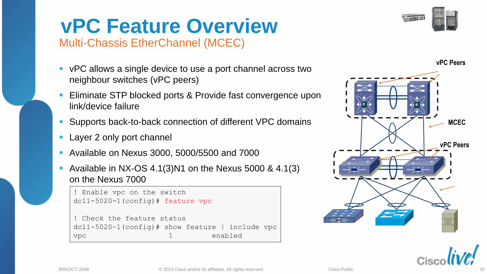
MCEC
! Enable vpc on the switch
dc11-5020-1(config)# feature vpc
! Check the feature status
dc11-5020-1(config)# show feature | include vpc
vpc 1 enabled
vPC Peers
vPC Feature Overview
vPC allows a single device to use a port channel across two
neighbour switches (vPC peers)
Eliminate STP blocked ports & Provide fast convergence upon
link/device failure
Supports back-to-back connection of different VPC domains
Layer 2 only port channel
Available on Nexus 3000, 5000/5500 and 7000
Available in NX-OS 4.1(3)N1 on the Nexus 5000 & 4.1(3)
on the Nexus 7000
Multi-Chassis EtherChannel (MCEC)
MCEC
vPC Peers
10
© 2013 Cisco and/or its affiliates. All rights reserved. BRKDCT-2048 Cisco Public
Agenda
Feature Overview
‒ vPC Concept & Benefits
‒ How does vPC help with STP?
‒ vPC Terminology
‒ Data-Plane Loop Avoidance with vPC
vPC Design Guidance and Best Practices
vPC Enhancements
Convergence and Scalability
Reference Material
11

© 2013 Cisco and/or its affiliates. All rights reserved. BRKDCT-2048 Cisco Public
Feature Overview How does vPC help with STP? (1 of 2)
Before vPC
STP blocks redundant uplinks
VLAN based load balancing
Loop Resolution relies on STP
Protocol Failure
Primary Root
Secondary Root
12
With vPC
No blocked uplinks
EtherChannel load balancing (hash)
Loop Free Topology
Lower oversubscription
© 2013 Cisco and/or its affiliates. All rights reserved. BRKDCT-2048 Cisco Public
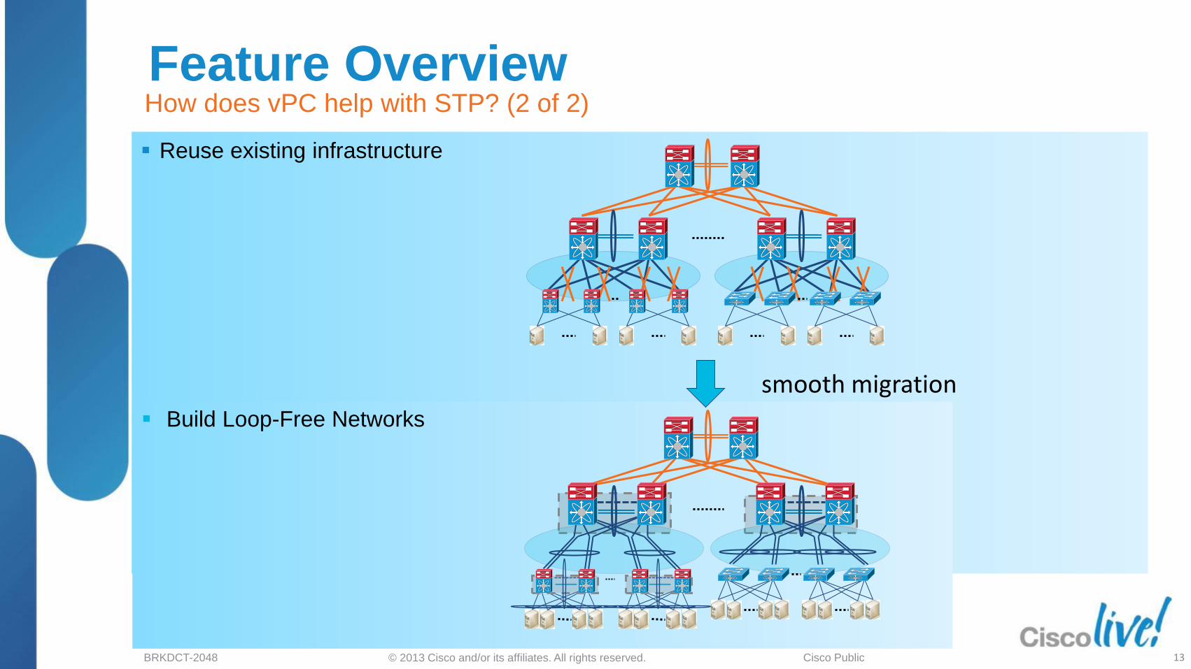
Feature Overview How does vPC help with STP? (2 of 2)
Reuse existing infrastructure
Build Loop-Free Networks
smooth migration
13

© 2013 Cisco and/or its affiliates. All rights reserved. BRKDCT-2048 Cisco Public
Agenda
Feature Overview
‒ vPC Concept & Benefits
‒ How does vPC help with STP?
‒ vPC Terminology
‒ Data-Plane Loop Avoidance with vPC
vPC Design Guidance and Best Practices
vPC Enhancements
Convergence and Scalability
Reference Material
14

© 2013 Cisco and/or its affiliates. All rights reserved. BRKDCT-2048 Cisco Public
Feature Overview
vPC Domain - A pair of vPC switches
vPC Peer - A vPC switch, one of a pair
vPC member port - one of a set
of ports (port channels) that form a vPC
vPC - the port channel between the vPC peer
and the downstream device
vPC peer-link - Link used to synchronise state
between vPC peer devices, must be 10GE
vPC peer-keepalive link - The keepalive link
between vPC peer devices
vPC Terminology (1 of 2)
vPC member
port
vPC
vPC member
port
vPC peer-link
vPC peer
vPC Domain
vPC vPC
member port
15
vPC Peer-keepalive link

© 2013 Cisco and/or its affiliates. All rights reserved. BRKDCT-2048 Cisco Public
Feature Overview vPC Terminology (2 of 2)
CFS protocol vPC VLAN - Any of the VLANs carried over the
peer-link and used to communicate via vPC with a
peer device
Non-vPC VLAN - Any of the STP VLANs not carried
over the peer-link
CFS - Cisco Fabric Services protocol, used for state
synchronisation and configuration validation between vPC
peer devices
Orphan Device – An orphan device is a device which is on a
VPC vlan but only connected to one VPC peer and not to both
Orphan Port – An orphan port is a interface which connects to
an orphan device
16
Orphan Port
Orphan Device

© 2013 Cisco and/or its affiliates. All rights reserved. BRKDCT-2048 Cisco Public
Agenda
Feature Overview
‒ vPC Concept & Benefits
‒ How does vPC help with STP?
‒ vPC Terminology
‒ Data-Plane Loop Avoidance with vPC
vPC Design Guidance and Best Practices
vPC Enhancements
Convergence and Scalability
Reference Material
17
© 2013 Cisco and/or its affiliates. All rights reserved. BRKDCT-2048 Cisco Public
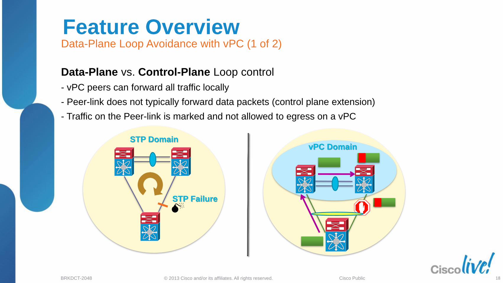
Feature Overview Data-Plane Loop Avoidance with vPC (1 of 2)
vPC Domain STP Domain
STP Failure
Data-Plane vs. Control-Plane Loop control
- vPC peers can forward all traffic locally
- Peer-link does not typically forward data packets (control plane extension)
- Traffic on the Peer-link is marked and not allowed to egress on a vPC
18

© 2013 Cisco and/or its affiliates. All rights reserved. BRKDCT-2048 Cisco Public
Feature Overview
Exception for single-sided vPC failures
Peer-link used as Backup path for optimal resiliency
Data-Plane Loop Avoidance with vPC (2 of 2)
vPC Domain
19
© 2013 Cisco and/or its affiliates. All rights reserved. BRKDCT-2048 Cisco Public
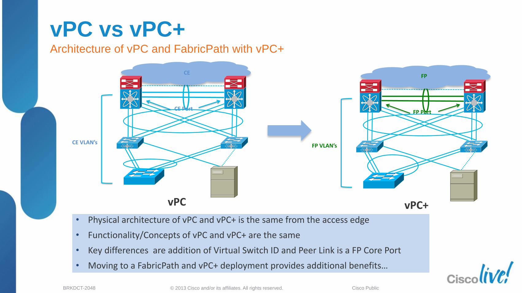
• Physical architecture of vPC and vPC+ is the same from the access edge
• Functionality/Concepts of vPC and vPC+ are the same
• Key differences are addition of Virtual Switch ID and Peer Link is a FP Core Port
• Moving to a FabricPath and vPC+ deployment provides additional benefits…
vPC vs vPC+ Architecture of vPC and FabricPath with vPC+
FP Port
FP VLAN’s
vPC+
FP
CE Port
CE VLAN’s
vPC
CE

vPC Design Guidance & Best Practices
21

© 2013 Cisco and/or its affiliates. All rights reserved. BRKDCT-2048 Cisco Public
Agenda
Feature Overview
vPC Design Guidance and Best Practices
‒ vPC Hardware Support
‒ Building a vPC Domain
‒ Mixed Chassis Mode
‒ Attaching to a vPC Domain
‒ Layer 3 and vPC
‒ Spanning Tree Recommendations
‒ Data Centre Interconnect
‒ HSRP with vPC
‒ vPC and Network Services
‒ vPC / FEX Supported Topologies
vPC Enhancements
Convergence and Scalability
Reference Material 22

© 2013 Cisco and/or its affiliates. All rights reserved. BRKDCT-2048 Cisco Public
vPC is now supported on the Nexus 3000 as of 5.0(3)U2(1) The maximum number of vPC configurable on the Cisco Nexus
3000 Series Switches is 64
vPC - Supported Hardware Nexus 3000
23

© 2013 Cisco and/or its affiliates. All rights reserved. BRKDCT-2048 Cisco Public
vPC - Supported Hardware
Nexus 7000
I/O Module vPC Peer-link
(10 GE Only) VPC Interfaces
N7K-M132XP-12
N7K-M132XP-12L ✓ ✓ N7K-M148GT-11
N7K-M148GT-11L
N7K-M148GS-11
N7K-M148GS-11L
✗ ✓
N7K-M108X2-12L ✓ ✓ N7K-M224XP-23L
N7K-M206FQ-23L
N7K-M202CF-22L ✓ ✓
N7K-F132XP-15 ✓ ✓ N7K-F248XP-25
N7K-F248XP-25E ✓ ✓
For Your Reference
24

© 2013 Cisco and/or its affiliates. All rights reserved. BRKDCT-2048 Cisco Public
Part Number / Chassis vPC Peer-link
(10 GE Only)
VPC Member Port
N5K-C5010P-BF ✓ ✓
N5K-C5020P-BF ✓ ✓
N5K-C5548P-FA ✓ ✓
N5K-C5548UP-FA ✓
✓
N5K-C5596UP-FA ✓ ✓
For Your Reference
vPC - Supported Hardware NEXUS 5000/5500
25

© 2013 Cisco and/or its affiliates. All rights reserved. BRKDCT-2048 Cisco Public
Part Number FEX
vPC Peerlink
vPC Member Port
NEXUS 5000 parent switch
NEXUS 7000 parent switch
N2K-C2148T-1GE ✗ ✓ ✗
N2K-C2224TP-1GE
N2K-C2248TP-1GE ✗ ✓ ✓
N2K-C2232PP-10GE
✗ ✓ ✓
N2K-C2232TM-10GE
✗ ✓ 6.1
N2K-B22-HP ✗ ✓ TBD
N2K-C2248TP-E-1GE ✗ ✓ 6.1
For Your Reference
vPC - Supported Hardware NEXUS 2000 platform
26

© 2013 Cisco and/or its affiliates. All rights reserved. BRKDCT-2048 Cisco Public
Agenda
Feature Overview
vPC Design Guidance and Best Practices
‒ vPC Hardware Support
‒ Building a vPC Domain
‒ Mixed Chassis Mode
‒ Attaching to a vPC Domain
‒ Layer 3 and vPC
‒ Spanning Tree Recommendations
‒ Data Centre Interconnect
‒ HSRP with vPC
‒ vPC and Network Services
‒ vPC / FEX Supported Topologies
vPC Enhancements
Convergence and Scalability
Reference Material 27

© 2013 Cisco and/or its affiliates. All rights reserved. BRKDCT-2048 Cisco Public
Building a vPC Domain Configuration Steps
5 6 7 8
1 2 3 4
Following steps are needed to build a vPC (Order does Matter!)
vPC member
Routed Interface
Host Port
Define domains*
Establish Peer Keepalive connectivity
Create a Peer link
Reuse port-channels and Create vPCs
Make Sure Configurations are Consistent
28

© 2013 Cisco and/or its affiliates. All rights reserved. BRKDCT-2048 Cisco Public
Building a vPC Domain vPC Domains
! Configure the vPC Domain ID – It should be unique within the layer 2 domain
NX-1(config)# vpc domain 20
! Check the vPC system MAC address
NX-1# show vpc role
<snip>
vPC system-mac : 00:23:04:ee:be:14
vPC Domain 20
vPC System MAC identifies the
Logical Switch in the network
topology
vPC Domain 10
vPC Domain defines the grouping of switches
participating in the vPC
Provides for definition of global vPC system parameters
The vPC peer devices use the vPC domain ID to
automatically assign a unique vPC system MAC address
You MUST utilise unique Domain id’s for all vPC
pairs defined in a contiguous layer 2 domain
29

© 2013 Cisco and/or its affiliates. All rights reserved. BRKDCT-2048 Cisco Public
5K_2#sh lacp neighbor
<snip>
LACP port Admin Oper Port Port
Port Flags Priority Dev ID Age key Key Number State
Gi1/1 SA 32768 0023.04ee.be14 9s 0x0 0x801E 0x4104 0x3D
Gi1/2 SA 32768 0023.04ee.be14 21s 0x0 0x801E 0x104 0x3D
7K_2 # sh vpc role
<snip>
vPC system-mac : 00:23:04:ee:be:14
vPC system-priority : 1024
vPC local system-mac : 00:0d:ec:a4:5f:7c
vPC local role-priority : 32667
7K_1# sh vpc role
<snip>
vPC system-mac : 00:23:04:ee:be:14
vPC system-priority : 1024
vPC local system-mac : 00:0d:ec:a4:53:3c
vPC local role-priority : 1024
dc11-4948-1
LACP neighbour sees the same System ID from both vPC peers
The vPC ‘system-mac’ is used by both vPC peers
5K_2
7K_1 7K_2
1/4 1/5
Regular (non vPC)
Port Channel 1/1
1/2
MCEC (vPC)
EtherChannel
Building a vPC Domain Independent Control Plane + Synchronised L2 State
30

© 2013 Cisco and/or its affiliates. All rights reserved. BRKDCT-2048 Cisco Public
dc11-4948-2#sh lacp neighbor
<snip>
LACP port Admin Oper Port Port
Port Flags Priority Dev ID Age key Key Number State
Gi1/4 SA 32768 000d.eca4.533c 8s 0x0 0x1D 0x108 0x3D
Gi1/5 SA 32768 000d.eca4.533c 8s 0x0 0x1D 0x108 0x3D
7k_1 # sh vpc role
<snip>
vPC system-mac : 00:23:04:ee:be:14
vPC system-priority : 1024
vPC local system-mac : 00:0d:ec:a4:53:3c
vPC local role-priority : 1024
vPC peers function as independent devices as well as peers
Local ‘system-mac’is used for all non vPC PDUs (LACP, STP, …)
MCEC (vPC)
EtherChannel 5K_2
7K_1 7K_2
1/4 1/5
Regular (non vPC)
Port Channel 1/1 1/2
dc11-4948--2
Building a vPC Domain Independent Control Plane + Synchronised L2 State
31

© 2013 Cisco and/or its affiliates. All rights reserved. BRKDCT-2048 Cisco Public
dc11-5020-3(config-vpc-domain)# role priority ?
<1-65535> Specify priority value
dc11-5020-3# sh vpc
<snip>
vPC role : secondary, operational primary
Secondary (but may be
Operational Primary)
Primary (but may be
Operational Secondary)
vPC Domain 20
vPC Domain 10 Dual Layer vPC
vPC primary switch election is based on role priority
Lower priority wins if not, lower system mac wins
Role is non-preemptive, So operational role is what
matters
Operational role may different from the priorities
configured under the domain
vPC role defines which of the two vPC peers
processes BPDUs
Role matters for the behaviour with peer-link failures!
32
Building a vPC Domain vPC Roles

© 2013 Cisco and/or its affiliates. All rights reserved. BRKDCT-2048 Cisco Public
Building a vPC Domain vPC Peer-Link ( aka VPC PL )
vPC peer-link
Definition:
‒ Standard 802.1Q Trunk which carries CFS (Cisco Fabric Services)
messages
‒ Carries flooded traffic from the vPC peer , STP BPDUs, HSRP
Hellos, IGMP updates, etc.
Requirements:
‒ Peer-Link member ports must be 10GE interfaces :
- 32 port 10GE (M1 or F1 series) or 8 port 10GE-X2 M1 modules
or 48 port 10GE F2
- Any 10G port on NEXUS 5000/5500 series
- vPC Peer-link should be a point-to-point connection
Recommendations (strong ones!)
‒ Minimum 2x 10GE ports
(on NEXUS 7000 : use 2 separate cards for best resiliency)
‒ 10GE ports in dedicated mode (for oversubscribed modules)
33
The peer link is always
forwarding for any VLAN
that is a member !
vPC imposes the rule that
the peer link should never
be blocking !
© 2013 Cisco and/or its affiliates. All rights reserved. BRKDCT-2048 Cisco Public
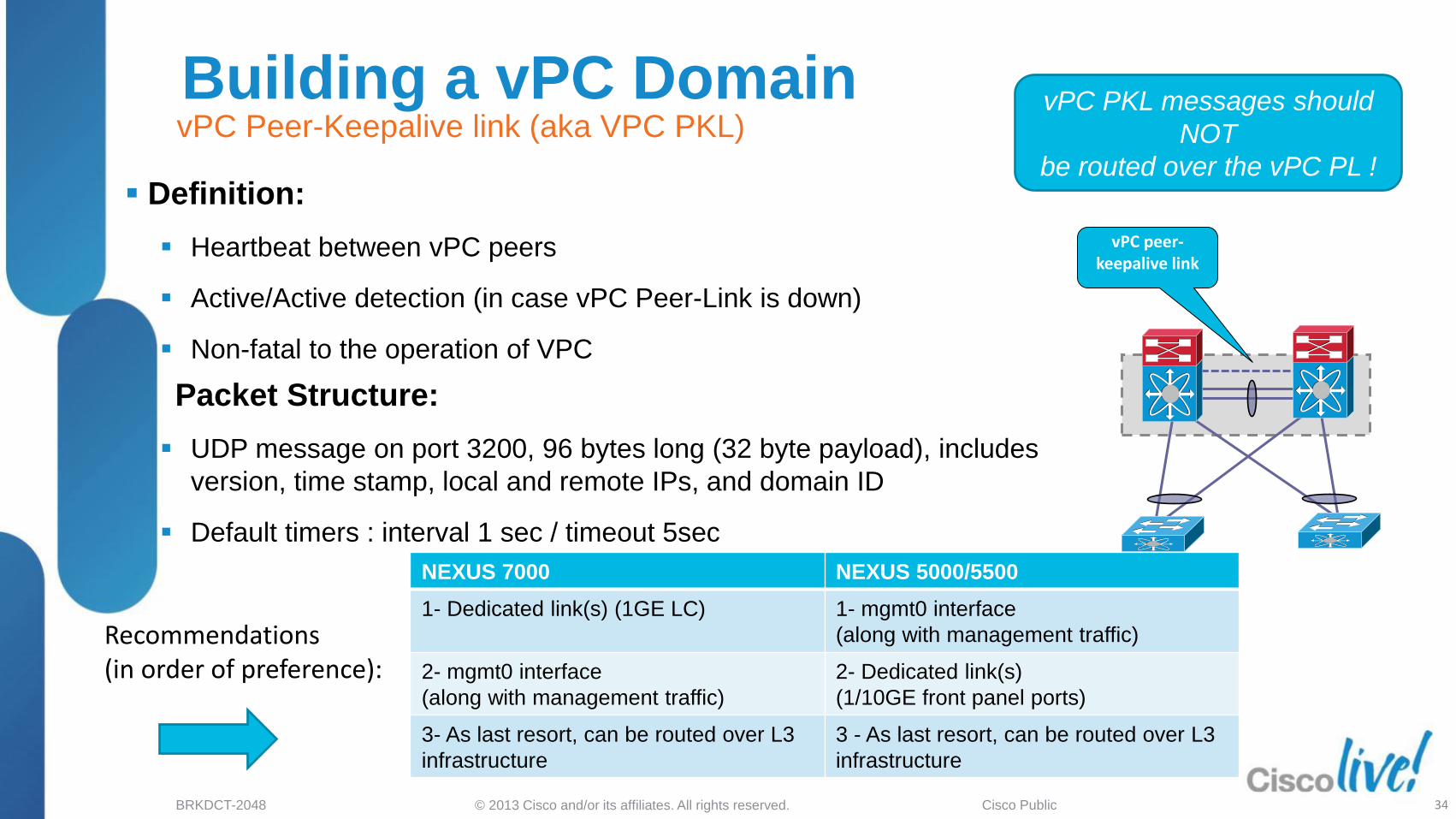
Building a vPC Domain vPC Peer-Keepalive link (aka VPC PKL)
vPC peer-keepalive link
NEXUS 7000 NEXUS 5000/5500
1- Dedicated link(s) (1GE LC) 1- mgmt0 interface
(along with management traffic)
2- mgmt0 interface
(along with management traffic)
2- Dedicated link(s)
(1/10GE front panel ports)
3- As last resort, can be routed over L3
infrastructure
3 - As last resort, can be routed over L3
infrastructure
Recommendations (in order of preference):
Definition:
Heartbeat between vPC peers
Active/Active detection (in case vPC Peer-Link is down)
Non-fatal to the operation of VPC
Packet Structure:
UDP message on port 3200, 96 bytes long (32 byte payload), includes
version, time stamp, local and remote IPs, and domain ID
Default timers : interval 1 sec / timeout 5sec
34
vPC PKL messages should
NOT
be routed over the vPC PL !

© 2013 Cisco and/or its affiliates. All rights reserved. BRKDCT-2048 Cisco Public
Building a vPC Domain vPC Peer-Keepalive link – Dual Supervisors on Nexus 7000
vPC1 vPC2
vPC_PL
Management Network
Standby Management Interface
Active Management Interface
Management Switch
vPC_PKL vPC_PKL
When using dual supervisors and mgmt0 interfaces to carry the vPC peer-keepalive,
do not connect them back to back between the two switches
Only one management port will be active a given point in time and a supervisor
switchover may break keep-alive connectivity
Use the management interface when you have an out-of-band management network
(management switch in between)
35

© 2013 Cisco and/or its affiliates. All rights reserved. BRKDCT-2048 Cisco Public
SW3 SW4
vPC1 vPC2
vPC_PLink
vPC Peer-keepalive
vPC Failure Scenario vPC Peer-Keepalive Link up & vPC Peer-Link down
Keepalive Heartbeat
Secondary vPC
P S
S
P Primary vPC
Suspend secondary
vPC Member Ports
vPC peer-link failure (link loss):
Check active status of the remote vPC peer via vPC peer-keepalive link (heartbeat)
If both peers are active, then Secondary vPC peer will disable all vPCs to avoid Dual-Active
Data will automatically forward down remaining active port channel ports
Failover gated on CFS message failure, or UDLD/Link state detection
Orphan devices connected to secondary peer will be isolated
36
© 2013 Cisco and/or its affiliates. All rights reserved. BRKDCT-2048 Cisco Public
SW3 SW4
vPC1 vPC2
vPC_PLink
vPC Peer-keepalive
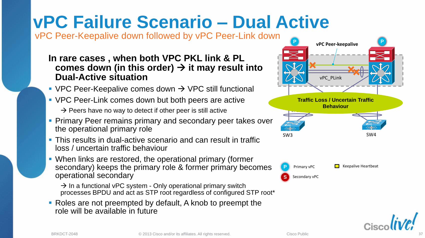
vPC Failure Scenario – Dual Active vPC Peer-Keepalive down followed by vPC Peer-Link down
Keepalive Heartbeat
Secondary vPC
P S
S
P Primary vPC
In rare cases , when both VPC PKL link & PL comes down (in this order) it may result into Dual-Active situation
VPC Peer-Keepalive comes down VPC still functional
VPC Peer-Link comes down but both peers are active
Peers have no way to detect if other peer is still active
Primary Peer remains primary and secondary peer takes over the operational primary role
This results in dual-active scenario and can result in traffic loss / uncertain traffic behaviour
When links are restored, the operational primary (former secondary) keeps the primary role & former primary becomes operational secondary
In a functional vPC system - Only operational primary switch processes BPDU and act as STP root regardless of configured STP root*
Roles are not preempted by default, A knob to preempt the role will be available in future
37
P
Traffic Loss / Uncertain Traffic
Behaviour

© 2013 Cisco and/or its affiliates. All rights reserved. BRKDCT-2048 Cisco Public
vPC Configuration Consistency vPC Control Plane - Consistency Check
Both switches in the vPC Domain maintain distinct control planes
CFS provides for protocol state sync between both peers (MAC Address table, IGMP state, …)
System configuration must also be kept in sync
Two types of interface consistency checks
Type 1 – Will put interfaces into suspend state to prevent incorrect forwarding of packets. With Graceful Consistency check (5.2 & later), we only suspend on secondary peer
Type 2 – Error messages to indicate potential for undesired forwarding behaviour
vPC Domain 20
vPC Domain 10
38

© 2013 Cisco and/or its affiliates. All rights reserved. BRKDCT-2048 Cisco Public
Type 1 Consistency Checks are intended to prevent network failures
Incorrect forwarding of traffic
Physical network incompatibilities
dc11-5020-2# show vpc brief
Legend:
(*) - local vPC is down, forwarding via vPC peer-link
<snip>
vPC status
--------------------------------------------------------------------------------------------------
id Port Status Consistency Reason Active vlans
------ ----------- ------ ----------- -------------------------- ---------------------------------
201 Po201 up failed vPC type-1 configuration -
incompatible - STP
interface port guard -
Root or loop guard
inconsistent
dc11-5020-1# sh run int po 201
interface port-channel201
switchport mode trunk
switchport trunk native vlan 100
switchport trunk allowed vlan 100-105
vpc 201
spanning-tree port type network
dc11-5020-2# sh run int po 201
interface port-channel201
switchport mode trunk
switchport trunk native vlan 100
switchport trunk allowed vlan 100-105
vpc 201
spanning-tree port type network
spanning-tree guard root “vPC will be suspended”
vPC Configuration Consistency vPC Control Plane – Type 1 Consistency Check
39

© 2013 Cisco and/or its affiliates. All rights reserved. BRKDCT-2048 Cisco Public
Type 2 Consistency Checks are intended to prevent undesired forwarding
vPC will be modified in certain cases (e.g. VLAN mismatch)
dc11-5020-1# show vpc brief vpc 201
vPC status
----------------------------------------------------------------------------
id Port Status Consistency Reason Active vlans
------ ----------- ------ ----------- -------------------------- -----------
201 Po201 up success success 100-104
2009 May 17 21:56:28 dc11-5020-1 %ETHPORT-5-IF_ERROR_VLANS_SUSPENDED: VLANs 105 on Interface port-
channel201 are being suspended. (Reason: Vlan is not configured on remote vPC interface)
dc11-5020-1# sh run int po 201
version 4.1(3)N1(1)
interface port-channel201
switchport mode trunk
switchport trunk native vlan 100
switchport trunk allowed vlan 100-105
vpc 201
spanning-tree port type network
dc11-5020-2# sh run int po 201
version 4.1(3)N1(1)
interface port-channel201
switchport mode trunk
switchport trunk native vlan 100
switchport trunk allowed vlan 100-104
vpc 201
spanning-tree port type network
“Inconsistent config will be disabled”
vPC Configuration Consistency vPC Control Plane – Type 2 Consistency Check
40
© 2013 Cisco and/or its affiliates. All rights reserved. BRKDCT-2048 Cisco Public
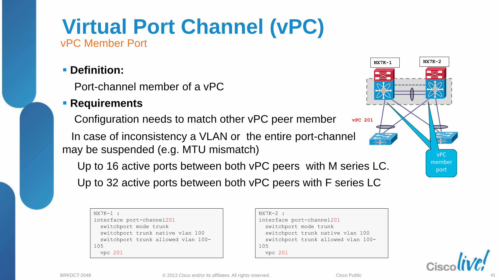
Virtual Port Channel (vPC) vPC Member Port
vPC member
port
vPC member
port
NX7K-2 :
interface port-channel201
switchport mode trunk
switchport trunk native vlan 100
switchport trunk allowed vlan 100-
105
vpc 201
NX7K-1 :
interface port-channel201
switchport mode trunk
switchport trunk native vlan 100
switchport trunk allowed vlan 100-
105
vpc 201
NX7K-1 NX7K-2
vPC 201
Definition:
Port-channel member of a vPC
Requirements
Configuration needs to match other vPC peer member
In case of inconsistency a VLAN or the entire port-channel
may be suspended (e.g. MTU mismatch)
Up to 16 active ports between both vPC peers with M series LC.
Up to 32 active ports between both vPC peers with F series LC
41
© 2013 Cisco and/or its affiliates. All rights reserved. BRKDCT-2048 Cisco Public
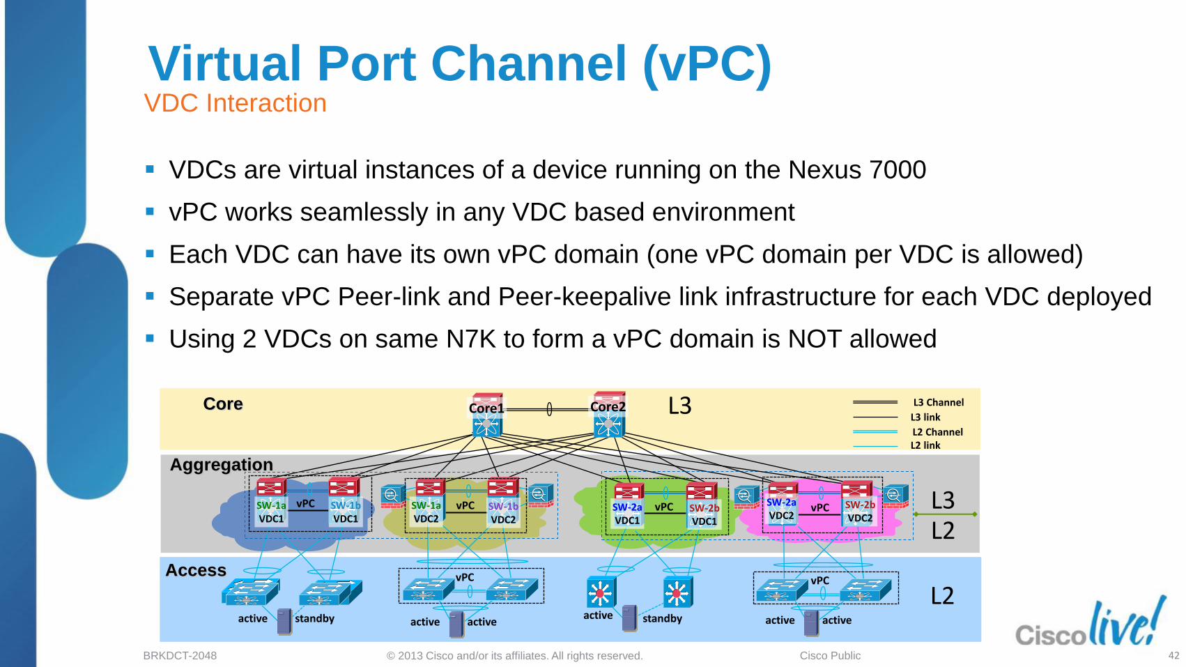
Virtual Port Channel (vPC)
VDCs are virtual instances of a device running on the Nexus 7000
vPC works seamlessly in any VDC based environment
Each VDC can have its own vPC domain (one vPC domain per VDC is allowed)
Separate vPC Peer-link and Peer-keepalive link infrastructure for each VDC deployed
Using 2 VDCs on same N7K to form a vPC domain is NOT allowed
VDC Interaction
L2 L3
L3
L2
L2 Channel
L3 link
L2 link
L3 Channel Core
Aggregation
Access
SW-2b VDC2
SW-2a VDC2
SW-2a VDC1
SW-2b VDC1
SW-1a VDC2
SW-1b VDC2
SW-1a VDC1
SW-1b VDC1
Core2 Core1
vPC vPC
active active active standby active active active standby
vPC vPC vPC vPC
42

© 2013 Cisco and/or its affiliates. All rights reserved. BRKDCT-2048 Cisco Public
Agenda
Feature Overview
vPC Design Guidance and Best Practices
‒ vPC Hardware Support
‒ Building a vPC Domain
‒ Mixed Chassis Mode
‒ Attaching to a vPC Domain
‒ Layer 3 and vPC
‒ Spanning Tree Recommendations
‒ Data Centre Interconnect
‒ HSRP with vPC
‒ vPC and Network Services
‒ vPC / FEX Supported Topologies
vPC Enhancements
Convergence and Scalability
Reference Material
43

© 2013 Cisco and/or its affiliates. All rights reserved. BRKDCT-2048 Cisco Public
M-Series provides scalable L2 and L3 tables
F1-Series provides high-density cost-effective Layer 2 10GbE connectivity
Mixing M-Series and F1-Series in aggregation switch (mixed chassis mode) provides several benefits :
Bridging traffic remain in F1-Series LC
Internal proxy routing via M-Series LC for routed traffic coming from F-Series LC
NEXUS 7000 with F1-series LC only can be used as modular access switch (no need for M-Series LC if L3 function is not required)
L3
L2
Mixed Chassis
Mode (M/F)
Chassis with
F1-Series LC
only Chassis with
M-Series LC only
vPC
M1 - F1 LC Design Considerations Mixed Chassis Mode
44

© 2013 Cisco and/or its affiliates. All rights reserved. BRKDCT-2048 Cisco Public
Mixed chassis (M/F) can operate with 1 M1 LC per chassis
M1 LC will provide all local routing capabilities for the chassis : inter-vlan routing and L3 northbound traffic
When M1 LC fails down on one of the N7Ks: Inter-VLAN traffic (vPC -> FHRP -> vPC) :
traffic gets dropped because of vPC loop avoidance rule
Upstream traffic (vPC -> FHRP -> L3) : traffic gets bridged on vPC peer-link to other NEXUS 7000 FHRP vMAC and then routed to L3 point
L3
L2
Chassis with F-Series
LC only Chassis with
M-Series LC only
M1 M1
OK
NOT OK
F F
M1 - F1 LC Design Considerations Mixed Chassis (M/F) Mode – 1 M1 LC only ; Peer-link on F1 Ports
45
Recommendation is to use at least 2 M1 LC in mixed mode chassis (M/F) with peer-link on F1 ports in order to provide redundancy for Proxy L3 Routing.
Mixed Chassis
Mode (M/F)

© 2013 Cisco and/or its affiliates. All rights reserved. BRKDCT-2048 Cisco Public
M1/M2 - F1/F2E LC Design Considerations vPC / Port-channel
vPC Peer-link S1 S2
vPC Primary vPC Secondary
F1 F1
vPC
vPC Peer-link S1 S2
vPC Primary vPC Secondary
F1/ F2 M1/M2
vPC
vPC Peer-link
S1 S2
vPC Primary vPC Secondary
M1 M1
vPC
vPC Peer-link S1 S2
vPC Primary vPC Secondary
F2 F2
vPC
46
Always use identical line cards on either sides of the peer link !
vPC Peer-link S1 S2
vPC Primary vPC Secondary
M1
vPC
M2
vPC Peer-link
S1 S2
vPC Primary vPC Secondary
M2 M2
vPC

© 2013 Cisco and/or its affiliates. All rights reserved. BRKDCT-2048 Cisco Public
vPC with F2 Modules
F2 vPCs does not support Dual DR for
L3 Multicast. This means no Proxy-DR
role in vPC with F2
Peer Link
Peer Link on a F2 module needs identical
modules (F2) on both sides
vPC Peer-link
S1 S2
vPC Primary vPC Secondary
F2 F2
vPC
NX-OS
N7K – NX-OS 6.0
Multicast with F2
F2 modules can not be mixed with M1 / F1 in the
same VDC ,F2 needs a dedicated F2-Only VDC
Recommendation for F2 is same as M1 ‒ Use at least 2 F2 line cards for redundancy both for peer
link and vpc member ports.
47

© 2013 Cisco and/or its affiliates. All rights reserved. BRKDCT-2048 Cisco Public
Agenda
Feature Overview
vPC Design Guidance and Best Practices
‒ vPC Hardware Support
‒ Building a vPC Domain
‒ Mixed Chassis Mode
‒ Attaching to a vPC Domain
‒ Layer 3 and vPC
‒ Spanning Tree Recommendations
‒ Data Centre Interconnect
‒ HSRP with vPC
‒ vPC and Network Services
‒ vPC / FEX Supported Topologies
vPC Enhancements
Convergence and Scalability
Reference Material
48

© 2013 Cisco and/or its affiliates. All rights reserved. BRKDCT-2048 Cisco Public
Attaching to a vPC Domain The Most Important Rule…
Dual Attach Devices
to a vPC Domain!!!
49

© 2013 Cisco and/or its affiliates. All rights reserved. BRKDCT-2048 Cisco Public
Orphan Ports
Orphan Ports
S P
4. Single Attached to vPC Device
S P
2. Attached via VDC/Secondary Switch
S P
3. Secondary inter switch Port-Channel (non-vPC VLAN)
1. Dual Attached
Primary vPC
Secondary vPC S
P
Attaching to a vPC Domain Dual Homed vs. Single Attached
S P
50

© 2013 Cisco and/or its affiliates. All rights reserved. BRKDCT-2048 Cisco Public
Agenda
Feature Overview
vPC Design Guidance and Best Practices
‒ vPC Hardware Support
‒ Building a vPC Domain
‒ Mixed Chassis Mode
‒ Attaching to a vPC Domain
‒ Layer 3 and vPC
‒ Spanning Tree Recommendations
‒ Data Centre Interconnect
‒ HSRP with vPC
‒ vPC and Network Services
‒ vPC / FEX Supported Topologies
vPC Enhancements
Convergence and Scalability
Reference Material
52

© 2013 Cisco and/or its affiliates. All rights reserved. BRKDCT-2048 Cisco Public
Routing Protocol Peer P
Router
Dynamic Peering Relationship
Switch
P
5k1 5k2
P
P
Nexus 7K Nexus 5K
Unicast
Traffic
× ✓
Multicast
Traffic
× ×
Platform Support
Dynamic Layer 3 peering over vPC
Layer 3 over vPC Unicast & Multicast
Dynamic Layer 3 peering support over VPC with F2 Modules on N7K is targeted for 6.2 release (1HCY12 )

© 2013 Cisco and/or its affiliates. All rights reserved. BRKDCT-2048 Cisco Public
Router
7k1 7k2
Switch
Po1
Po2
N7K Layer 3 and vPC Designs
Use L3 links to hook up routers and peer with a vPC domain
Don’t use L2 port channel to attach routers to a vPC domain unless you statically route to HSRP
address
If both, routed and bridged traffic is required, use individual L3 links for routed traffic and L2 port-
channel for bridged traffic
Layer 3 and vPC Design Recommendation
Router
Switch
L3 ECMP
Po2
P P
P
Routing Protocol Peer
Dynamic Peering Relationship
P
P P P
P P
57
Layer 3 Link

© 2013 Cisco and/or its affiliates. All rights reserved. BRKDCT-2048 Cisco Public
Routing Protocol Peer
N7K Layer 3 and vPC Designs Layer 3 and vPC Interactions: Supported Designs
Switch
7k1 *
Po1
7k2 *
P
P
Router/Switch
1. Peering between Routers
7k1 7k2
Dynamic Peering Relationship
2. Peering with an external Router on Routed ports inter-connection
P
P
Switch
P
Routed Link
P
* Nexus 7000 configured for L2 Transport only
For Your Reference
58

© 2013 Cisco and/or its affiliates. All rights reserved. BRKDCT-2048 Cisco Public
N7K Layer 3 and vPC Designs Layer 3 and vPC Interactions: Supported Designs
P
P P
7k1 7k2
2. Peering over an STP inter-connection NOT using a vPC VLAN (Orange VLANs/Links)
7k1 *
7k2 *
7k3 *
7k4 *
3. Peering between 2 routers with vPC devices as transit Switches
P P
Switch
7k1
Po1
7k2
1. Peering between vPC Device
P P
Routing Protocol Peer
Router/Switch
P
Dynamic Peering Relationship
Switch
* Nexus 7000 configured for L2 Transport only
For Your Reference
59

© 2013 Cisco and/or its affiliates. All rights reserved. BRKDCT-2048 Cisco Public
N7K Layer 3 and vPC Designs Layer 3 and vPC Interactions: Supported Designs
7k1
P P
P P
7k2
7k3
7k4
2. Peering over a vPC inter-connection (DCI case) on parallel Routed ports inter-connection
1. Peering with an external Router on parallel Routed ports inter-connection
P
7k1 7k2
P
P
7k1
Po1
7k2
P P
P P 3. Peering over PC inter-connection and dedicated inter-switch link using non-vPC VLAN
For Your Reference
60

© 2013 Cisco and/or its affiliates. All rights reserved. BRKDCT-2048 Cisco Public
N7K Layer 3 and vPC Designs Layer 3 and vPC Interactions: Unsupported Designs
Router
7k1
Po1
7k2
P P
P
4. Peering over PC inter-connection and over vPC peer-link using vPC VLAN
P
P P
7k1 7k2
2. Peering over an STP inter-connection using a vPC VLAN
7k1
P
P P
7k2
7k3
7k4
3. Peering over a vPC inter-connection (DCI case)
Router
7k1
Po1
7k2
P P
P
1. Peering over a vPC inter-connection
P
For Your Reference
61

© 2013 Cisco and/or its affiliates. All rights reserved. BRKDCT-2048 Cisco Public
Agenda
Feature Overview
vPC Design Guidance and Best Practices
‒ vPC Hardware Support
‒ Building a vPC Domain
‒ Mixed Chassis Mode
‒ Attaching to a vPC Domain
‒ Layer 3 and vPC
‒ Spanning Tree Recommendations
‒ Data Centre Interconnect
‒ HSRP with vPC
‒ vPC and Network Services
‒ vPC / FEX Supported Topologies
vPC Enhancements
Convergence and Scalability
Reference Material
62

© 2013 Cisco and/or its affiliates. All rights reserved. BRKDCT-2048 Cisco Public
Spanning Tree Recommendations STP and vPC Interoperability
STP is running to manage
loops outside of vPC domain,
or before initial vPC
configuration !
STP Uses:
- Loop detection (failsafe to vPC)
- Non-vPC attached device
- Loop management on vPC addition/removal
Requirements:
- Needs to remain enabled, but doesn’t dictate vPC member port state
- Logical ports still count
Best Practices:
- Make sure all switches in your layer 2 domain are running with Rapid-PVST or MST, to avoid slow
STP convergence (30+ secs)
- Remember to configure portfast (edge port-type) on host facing interfaces to avoid slow STP
convergence (30+ secs)
63
© 2013 Cisco and/or its affiliates. All rights reserved. BRKDCT-2048 Cisco Public
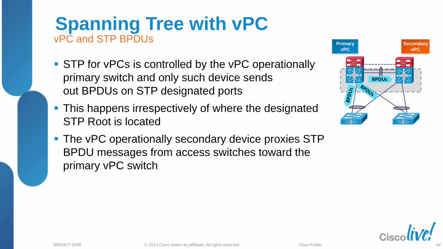
Spanning Tree with vPC
STP for vPCs is controlled by the vPC operationally
primary switch and only such device sends
out BPDUs on STP designated ports
This happens irrespectively of where the designated
STP Root is located
The vPC operationally secondary device proxies STP
BPDU messages from access switches toward the
primary vPC switch
vPC and STP BPDUs Primary
vPC
Secondary
vPC
BPDUs
64
© 2013 Cisco and/or its affiliates. All rights reserved. BRKDCT-2048 Cisco Public
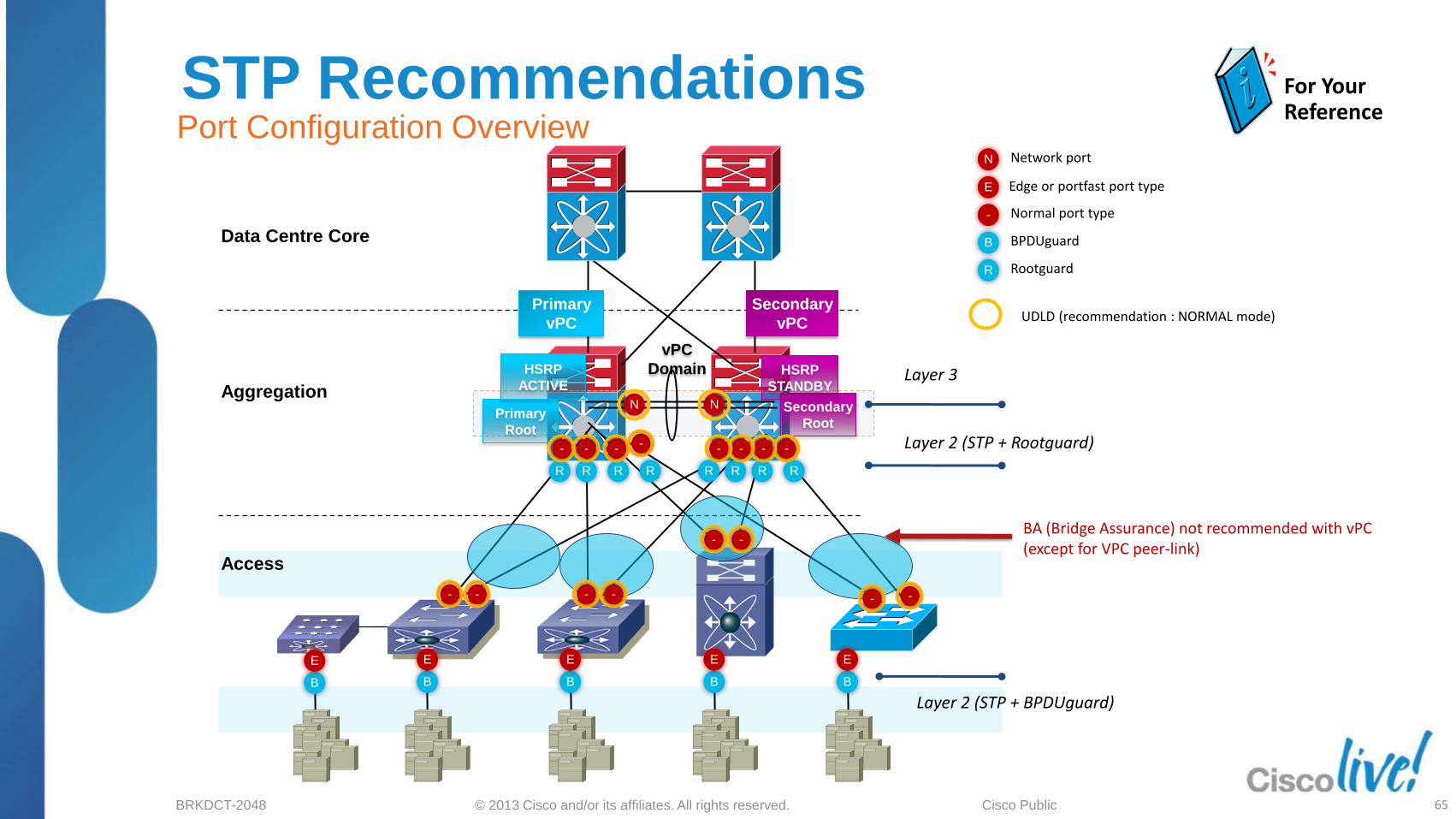
Aggregation
Access
Data Centre Core B
R
N
E
BPDUguard
Rootguard
Network port
Edge or portfast port type
- Normal port type
B
R R R R R R R R
B
E
B B
E
B
E
Layer 3
Layer 2 (STP + Rootguard)
Layer 2 (STP + BPDUguard)
E
Secondary
Root
HSRP
STANDBY
Primary
Root
HSRP
ACTIVE
E
Primary
vPC
Secondary
vPC
vPC
Domain
UDLD (recommendation : NORMAL mode)
N N
- - - - - - - -
- - - -
- -
For Your Reference
STP Recommendations Port Configuration Overview
BA (Bridge Assurance) not recommended with vPC (except for VPC peer-link)
- -
65

© 2013 Cisco and/or its affiliates. All rights reserved. BRKDCT-2048 Cisco Public
ISSU / ISSD with vPC
ISSU is the recommended system upgrade in a multi-device vPC environment
vPC system can be independently upgraded with no disruption to traffic
Upgrade is serialised and must be run one peer at a time (config lock will prevent synchronous upgrades)
Configuration is locked on “other” vPC peer during ISSU
Similar process of downgrades (ISSD)
Check ISSU / ISSD compatibility matrix & ensure ISSU is supported from current to target release
http://www.cisco.com/en/US/docs/switches/datacenter/sw/5_x/nx-os/release/notes/52_nx-os_release_note.html#wp423588
67
5.2(x) / 6.0(x)

© 2013 Cisco and/or its affiliates. All rights reserved. BRKDCT-2048 Cisco Public
Agenda
Feature Overview
vPC Design Guidance and Best Practices
‒ vPC Hardware Support
‒ Building a vPC Domain
‒ Mixed Chassis Mode
‒ Attaching to a vPC Domain
‒ Layer 3 and vPC
‒ Spanning Tree Recommendations
‒ Data Centre Interconnect
‒ HSRP with vPC
‒ vPC and Network Services
‒ vPC / FEX Supported Topologies
vPC Enhancements
Convergence and Scalability
Reference Material
68

© 2013 Cisco and/or its affiliates. All rights reserved. BRKDCT-2048 Cisco Public
Internal Network
Active/Active Application Processing
Database Processing
Internal Network
Active/Active Web Hosting
Data Centre Interconnect Ethernet Extensions for Clustering & Workload Mobility
Internet Service Provider A
Service Provider B
Many applications require L2/LAN connectivity Distributing applications requires LAN extensions across DCs
69
© 2013 Cisco and/or its affiliates. All rights reserved. BRKDCT-2048 Cisco Public
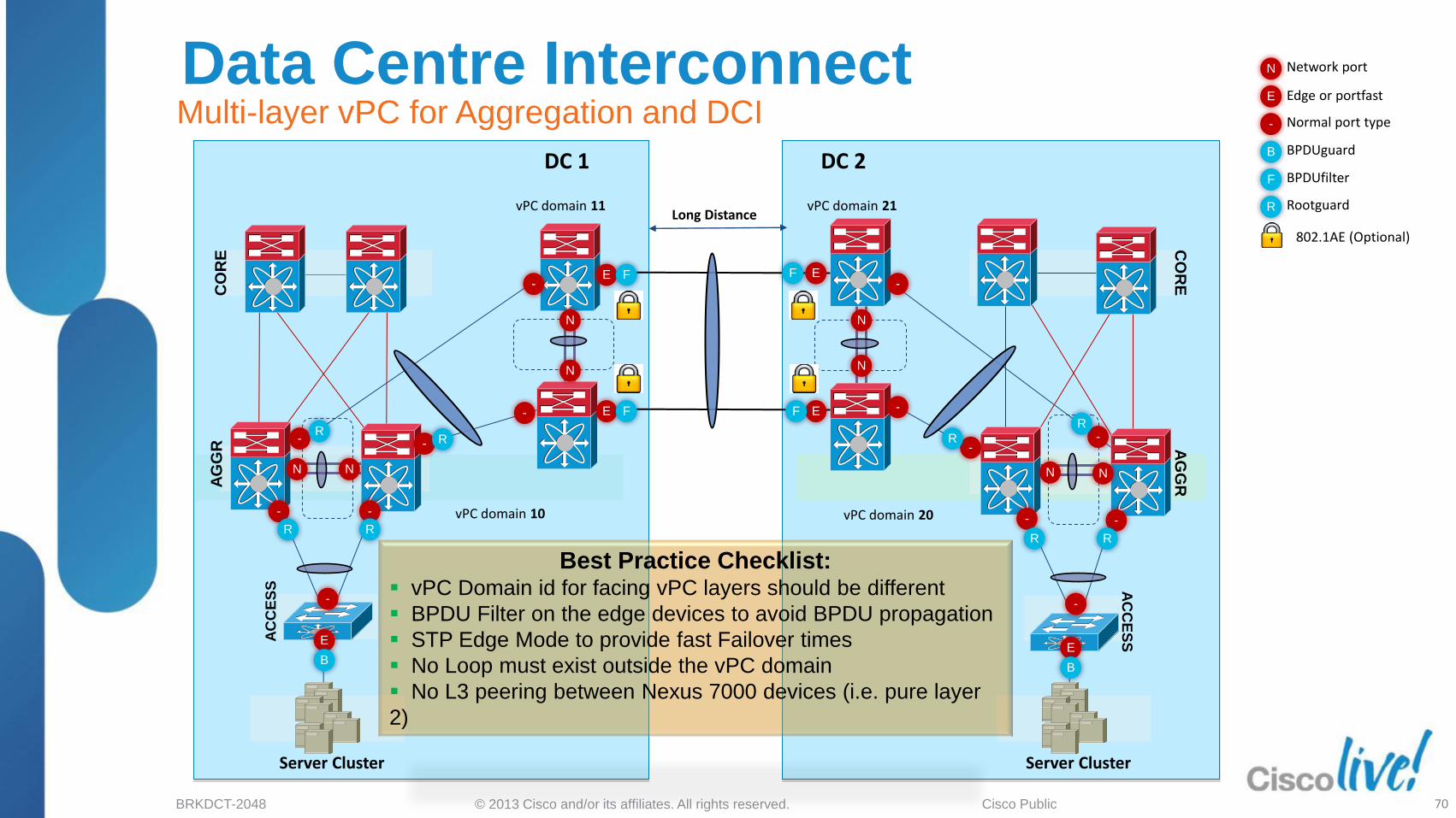
Long Distance
DC 1 DC 2
CO
RE
A
GG
R
AC
CE
SS
Server Cluster
CO
RE
A
GG
R
AC
CE
SS
Server Cluster
Best Practice Checklist: vPC Domain id for facing vPC layers should be different
BPDU Filter on the edge devices to avoid BPDU propagation
STP Edge Mode to provide fast Failover times
No Loop must exist outside the vPC domain
No L3 peering between Nexus 7000 devices (i.e. pure layer
2)
vPC domain 10 vPC domain 20
vPC domain 21 vPC domain 11
Data Centre Interconnect Multi-layer vPC for Aggregation and DCI
Rootguard
B
F
N
E
BPDUguard
BPDUfilter
Network port
Edge or portfast
- Normal port type
R
802.1AE (Optional)
E E
- -
- -
- -
E
E
E
E
F
F
F
F -
-
- -
-
- -
B
N N
N
N N
N
R
R
-
R R R R
R R
N N
B
70

© 2013 Cisco and/or its affiliates. All rights reserved. BRKDCT-2048 Cisco Public
Agenda
Feature Overview
vPC Design Guidance and Best Practices
‒ vPC Hardware Support
‒ Building a vPC Domain
‒ Mixed Chassis Mode
‒ Attaching to a vPC Domain
‒ Layer 3 and vPC
‒ Spanning Tree Recommendations
‒ Data Centre Interconnect
‒ FHRP with vPC
‒ vPC and Network Services
‒ vPC / FEX Supported Topologies
vPC Enhancements
Convergence and Scalability
Reference Material
71

© 2013 Cisco and/or its affiliates. All rights reserved. BRKDCT-2048 Cisco Public
FHRP with vPC
Support for all FHRP protocols in
Active/Active mode with vPC
No additional configuration required
Standby device communicates
with vPC manager to determine
if vPC peer is “Active” FHRP peer
When running active/active,
aggressive timers can be relaxed (i.e. 2-router vPC case)
Define SVIs associated with FHRP as routing passive-interfaces in order to
avoid routing adjacencies over vPC peer-link
‘peer-gateway’ command allows a vPC peer to respond both the HSRP virtual
and the real MAC address of both itself and it’s peer
Recommendation is to use default HSRP timers as both switches are active
HSRP / VRRP Active/Active
L3 L2
HSRP/VRRP “Standby”: Active
for shared L3 MAC
HSRP/VRRP “Active”: Active
for shared L3 MAC
72

© 2013 Cisco and/or its affiliates. All rights reserved. BRKDCT-2048 Cisco Public
L3 L2
OSPF/EIGRP
Primary
vPC
Secondary
vPC
OSPF/EIGRP
VLAN 99
FHRP with vPC
Point-to-point dynamic routing
Protocol adjacency between the vPC
peers to establish a L3 backup path
to the Core through PL in case of
uplinks failure
Use an L3 point-to-point link between vPC
peers to establish a L3 backup path to the
Core in case of uplinks failure
A single point-to-point VLAN/SVI will
suffice to establish a L3 neighbour
Backup Routing Path
Routing Protocol Peer P
P
P
P
P
73

© 2013 Cisco and/or its affiliates. All rights reserved. BRKDCT-2048 Cisco Public
FHRP with vPC Dual L2/L3 Pod Interconnect
Active Standby Listen Listen
Scenario:
Provide L2/L3 interconnect between L2 Pods, or
between L2 attached Datacentres (i.e. sharing the
same HSRP group)
DCI with a single HSRP:
Support for Active/Active on one pair, and still
allows normal HSRP behaviour on other pair (all
in one HSRP group)
In the first phase L3 traffic will run across Intra-pod
link for non Active/Active L3 pair
Use FHRP filtering to filter FHRP messages
across DCs and achieve active /active FHRP
states in both DCs with same FHRP groups
More details are at the url below : http://www.cisco.com/en/US/docs/solutions/Enterprise/Data_Center
/DCI/4.0/EMC/EMC_2.html#wp1261584
74

© 2013 Cisco and/or its affiliates. All rights reserved. BRKDCT-2048 Cisco Public
Agenda
Feature Overview
vPC Design Guidance and Best Practices
‒ vPC Hardware Support
‒ Building a vPC Domain
‒ Mixed Chassis Mode
‒ Attaching to a vPC Domain
‒ Layer 3 and vPC
‒ Spanning Tree Recommendations
‒ Data Centre Interconnect
‒ HSRP with vPC
‒ vPC and Network Services
‒ vPC / FEX Supported Topologies
vPC Enhancements
Convergence and Scalability
Reference Material
75

© 2013 Cisco and/or its affiliates. All rights reserved. BRKDCT-2048 Cisco Public
vPC and Network Services Services Chassis w. Services VDC Sandwich
Two Nexus 7000 Virtual Device Contexts to “sandwich” services between virtual switching layers
Layer-2 switching in Services Chassis with transparent services
Services Chassis provides portchannel capabilities for interaction with vPC
vPC running in both VDC pairs to provide portchannel for both inside and outside interfaces to Services Chassis
Design considerations:
Access switches requiring services are connected to sub-aggregation VDC
Access switches not requiring services be connected to aggregation VDC
If Peering at Layer 3 is required between vPC layers an alternative design should be explored (i.e. using STP rather than vPC to attach service chassis) or using static routing
76

© 2013 Cisco and/or its affiliates. All rights reserved. BRKDCT-2048 Cisco Public
vPC and Network Services Service Appliances
Static FHRP
agg1b agg1a
L3 FW L3 FW VPC VPC
State/Keepalive
Static VIP
Static VIP
Static FHRP
vPC_PKL
vPC_PL routing peer
vPC_PL
agg1b agg1a
L3 FW L3 FW
Non-vPC VLANs
State/Keepalive
Non-VPC VLANs Non-vPC VLANs
routing peer
vPC_PKL
A
A
B
B
Dedicate a L2 port-channel for the service appliances state and keepalive VLANs
Connect service appliances to vPC domain via vPC and configure static routes to
HSRP address
Implementing a separate L2 port channel for non-vPC VLANs to support single
attached devices without creating orphan ports
77

© 2013 Cisco and/or its affiliates. All rights reserved. BRKDCT-2048 Cisco Public
Agenda
Feature Overview
vPC Design Guidance and Best Practices
‒ vPC Hardware Support
‒ Building a vPC Domain
‒ Mixed Chassis Mode
‒ Attaching to a vPC Domain
‒ Layer 3 and vPC
‒ Spanning Tree Recommendations
‒ Data Centre Interconnect
‒ HSRP with vPC
‒ vPC and Network Services
‒ vPC / FEX Supported Topologies
vPC Enhancements
Convergence and Scalability
Reference Material
79

© 2013 Cisco and/or its affiliates. All rights reserved. BRKDCT-2048 Cisco Public
1
standby active
server: active/standby
NIC teaming
2
standby active
server: active/standby
NIC teaming
3
active active
server: active/active
no NIC teaming
4
Local FEX
port-Channel
server:NIC teaming (active-active)
5
active active
server: NIC teaming (active-active)
standby active
server: active/standby NIC teaming
6 8 7
Port-Channel on HIF (Host Interfaces supported)
-vPC to Host supported
For Your Reference vPC Supported Topologies
Nexus 7000 and 5000
80

© 2013 Cisco and/or its affiliates. All rights reserved. BRKDCT-2048 Cisco Public
standby active
vPC
vPC
Domain
active active
vPC
vPC
Domain
vPC
vPC vPC
Domain
8 9 10
New
For Your Reference
vPC Supported Topologies Nexus 5000 Only
81
Dual-homed FEX
w/ A-S Server Dual-homed FEX
w/ Single NIC Server
Enhanced vPC
N5500 only

© 2013 Cisco and/or its affiliates. All rights reserved. BRKDCT-2048 Cisco Public
active
7
active
11
active active
vPC
Domain
vPC
8 12
VDC1 VDC2
active active vPC
8 13
vPC
vPC
For Your Reference
vPC Unsupported Topologies
82
VPC Across two VDCs
on one Nexus 7000

vPC Enhancements
83

© 2013 Cisco and/or its affiliates. All rights reserved. BRKDCT-2048 Cisco Public
Agenda
Feature Overview
vPC Design Guidance and Best Practices
‒ vPC Hardware Support
‒ Building a vPC Domain
‒ Mixed Chassis Mode
‒ Attaching to a vPC Domain
‒ Layer 3 and vPC
‒ Spanning Tree Recommendations
‒ Data Centre Interconnect
‒ HSRP with vPC
‒ vPC and Network Services
‒ vPC / FEX Supported Topologies
vPC Enhancements
Convergence and Scalability
Reference Material
84
© 2013 Cisco and/or its affiliates. All rights reserved. BRKDCT-2048 Cisco Public 85
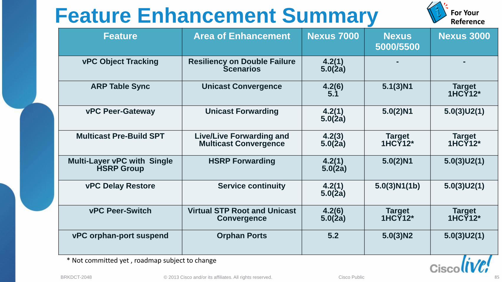
Feature Area of Enhancement Nexus 7000 Nexus 5000/5500
Nexus 3000
vPC Object Tracking Resiliency on Double Failure Scenarios
4.2(1) 5.0(2a)
- -
ARP Table Sync Unicast Convergence 4.2(6) 5.1
5.1(3)N1 Target 1HCY12*
vPC Peer-Gateway Unicast Forwarding 4.2(1) 5.0(2a)
5.0(2)N1 5.0(3)U2(1)
Multicast Pre-Build SPT Live/Live Forwarding and Multicast Convergence
4.2(3) 5.0(2a)
Target 1HCY12*
Target 1HCY12*
Multi-Layer vPC with Single HSRP Group
HSRP Forwarding 4.2(1) 5.0(2a)
5.0(2)N1 5.0(3)U2(1)
vPC Delay Restore Service continuity 4.2(1) 5.0(2a)
5.0(3)N1(1b) 5.0(3)U2(1)
vPC Peer-Switch
Virtual STP Root and Unicast Convergence
4.2(6) 5.0(2a)
Target 1HCY12*
Target 1HCY12*
vPC orphan-port suspend Orphan Ports 5.2 5.0(3)N2 5.0(3)U2(1)
Feature Enhancement Summary For Your Reference
* Not committed yet , roadmap subject to change

© 2013 Cisco and/or its affiliates. All rights reserved. BRKDCT-2048 Cisco Public 86
Feature Area of Enhancement
Nexus 7000 Nexus 5000/5500
Nexus 3000
Multicast suppression on vPC peer-link
Capacity Target 2HCY12* 5.0(3)N1 Target 1HCY12*
PVLAN on vPC Functionality Target 2HCY12* 4.2(1)N2 Target CY12*
vPC Auto Recovery Convergence 5.2 5.0(2)N1 5.0(3)U2(1)
Per VLAN Type 1 Consistency Checks
Consistency Check 5.2 5.0(2)N1 5.0(3)U2(1)
Graceful vPC type-1 check handling
Consistency Check 5.2 and 4.2.8 5.0(2)N1 5.0(3)U2(1)
Host vPC to FEX Redundancy 5.2 4.2(1)N1 N.A.
vPC config-sync Consistency Check Target 2HCY12* 5.0(2)N1 5.0(3)U2(1)
vPC+ Support for FabricPath 5.1 5.1(3)N1 N.A.
Feature Enhancement Summary For Your Reference
* Not committed yet , roadmap subject to change
© 2013 Cisco and/or its affiliates. All rights reserved. BRKDCT-2048 Cisco Public
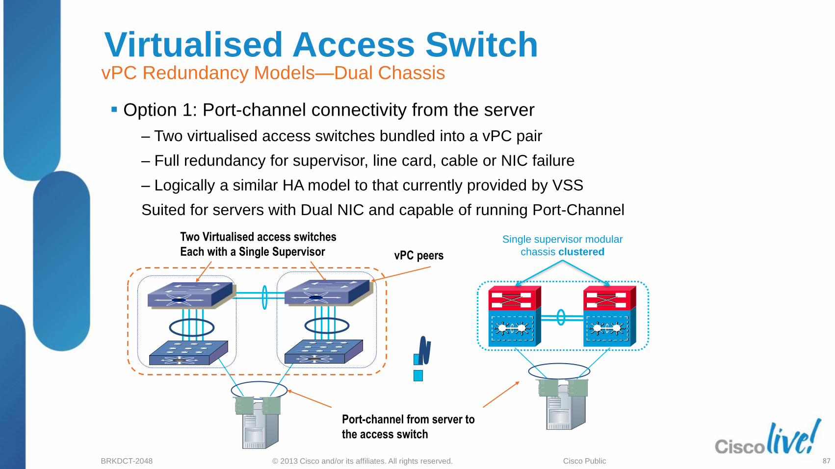
Virtualised Access Switch vPC Redundancy Models—Dual Chassis
Port-channel from server to
the access switch
vPC peers
Two Virtualised access switches
Each with a Single Supervisor Single supervisor modular
chassis clustered
Option 1: Port-channel connectivity from the server
‒ Two virtualised access switches bundled into a vPC pair
‒ Full redundancy for supervisor, line card, cable or NIC failure
‒ Logically a similar HA model to that currently provided by VSS
Suited for servers with Dual NIC and capable of running Port-Channel
87

© 2013 Cisco and/or its affiliates. All rights reserved. BRKDCT-2048 Cisco Public
Virtualised Access Switch vPC Redundancy Models—Dual Supervisor
Dual supervisor
modular chassis
Fabric Extender dual homed to
redundant Nexus 5000
Option 2: Fabric Extender connected to two Nexus 5000
‒From the server perspective a single access switch with each line card supported by redundant
supervisors
‒Full redundancy for supervisor, fabric via vPC and cable or NIC failure via active/standby NIC
redundancy
‒Logically a similar HA model to that currently provided by dual supervisor based modular
switch.
Suited for servers with Single NIC or Dual NIC but cant run Port-Channel
88

© 2013 Cisco and/or its affiliates. All rights reserved. BRKDCT-2048 Cisco Public
Redundancy with Enhanced vPC Data, Control and Management Plane Redundancy
Dual supervisor
modular chassis clustered Fabric Extender dual homed to
redundant Nexus 5000
NX-OS
N5K – 5.1 (3)
New vPC Option — Port-channel connectivity to dual-homed FEXs
‒ From the server perspective a single access switch with port-channel support – each line card
supported by redundant supervisors
‒ Full redundancy for supervisor, linecard, fabric via vPC and cable or NIC failure via Port-
channeling
‒Logically a similar HA model to that currently provided by dual supervisor based modular
switch.
89
Suited for all types
of servers.

© 2013 Cisco and/or its affiliates. All rights reserved. BRKDCT-2048 Cisco Public
Enhanced vPC ( aka Dual Tier vPC) Supported on Nexus 5500 only
Any Flavor of Nexus 5500 5548P/5548UP/5596UP
Any Flavor of Nexus 2000 2148T/2248TP/2224TP
2232PP/2232TM
Dual-homed Fabric Extenders
Mix of Single NIC, Active/Standby and Etherchanneled servers can connect to same FEX
Supported on N5500 Only
N5K – 5.1 (3) Release
90

© 2013 Cisco and/or its affiliates. All rights reserved. BRKDCT-2048 Cisco Public
vPC Graceful Type-1 Check
CE-1
S2-Secondary S1 -Primary
vPC peer-link
vPC 1
po1
Keepalive
vPC member ports on S1 and S2 should
have identical parameters (MTU, speed, …)
Any inconsistency in such parameters is
Type 1 all vlans on both vpc legs are
brought down in such Inconsistency
With graceful type-1 check, only Secondary
vPC members are brought down.
vPC member ports on primary peer device
remain up
S1(config-vpc-domain)# graceful consistency-check
S2(config-vpc-domain)# graceful consistency-check
Graceful Type-1 check enabled by default.
Type-1 Inconsistency
NX-OS
N7K - 5.2
N5K - 5.0(3)N1(1)
92

© 2013 Cisco and/or its affiliates. All rights reserved. BRKDCT-2048 Cisco Public
vPC Supported Server fails over
correctly
Active/Standby Server does not fail over correctly since orphan port is still
active
vPC
Orphan-Port Suspend vPC Active / Standby NIC teaming support
N5K-2(config)# int eth 100/1/1
N5K-2(config-if)# vpc orphan-port suspend
NX-OS
N7K - 5.2
N5K - 5.0(3) N2
eth 100/1/1
A vPC orphan port is an non-vPC interface on a switch where
other ports in the same VLAN are configured as vPC interfaces
vPC orphan ports have historically been problematic for mixed
server topologies
Prior to release 5.0(3)N2 on Nexus 5000/5500 and 5.2 on Nexus
7000 an orphan port was ‘not’ shut down on loss of vPC peer-
links
With the supported release the orphan ports on the vPC
secondary peer can (configurable) also be shut down triggering
NIC teaming recovery for all teaming configurations
Configuration is applied to the physical port*
95
* ‘VPC orphan-port suspend’ command does not currently work with FEX interface for a FEX connected to N7K due to CSCua35190

Convergence & Scalability
99

© 2013 Cisco and/or its affiliates. All rights reserved. BRKDCT-2048 Cisco Public
Agenda
Feature Overview
vPC Design Guidance and Best Practices
vPC Enhancements
Convergence and Scalability
Reference Material
100

© 2013 Cisco and/or its affiliates. All rights reserved. BRKDCT-2048 Cisco Public
vPC Scalability
For Latest Scalability numbers please refer to the scalability limits pages for the platform
Nexus 7000: N7K Verified Scalability Guide :
http://www.cisco.com/en/US/docs/switches/datacenter/sw/verified_scalability/b_Cisco_Nexus_7000_Series_NX-
OS_Verified_Scalability_Guide.html
Nexus 5000 /5500
http://www.cisco.com/en/US/docs/switches/datacenter/nexus5000/sw/configuration_limits/limits_513/nexus_5000_config_limits_
513.html
Nexus 3000 http://www.cisco.com/en/US/docs/switches/datacenter/nexus3000/sw/configuration_limits/503_u2_2/b_Nexus3K_Configuratio
n_Limits_for_Cisco_NXOS_Release_503_u2_2.html
102

Reference Material
103

© 2013 Cisco and/or its affiliates. All rights reserved. BRKDCT-2048 Cisco Public
Agenda
Feature Overview
vPC Design Guidance and Best Practices
vPC Enhancements
Convergence and Scalability
Reference Material
104

© 2013 Cisco and/or its affiliates. All rights reserved. BRKDCT-2048 Cisco Public
Reference Material
For Your Reference
vPC white Paper:
http://www.cisco.com/en/US/prod/collateral/switches/ps9441/ps9402/white_paper_c11-516396.html
vPC design guides:
http://www.cisco.com/en/US/partner/products/ps9670/products_implementation_design_guides_list.html
vPC and VSS Interoperability white Paper:
http://www.cisco.com/en/US/prod/collateral/switches/ps5718/ps708/white_paper_c11_589890.html
Data Centre Design—IP Network Infrastructure:
http://www.cisco.com/en/US/docs/solutions/Enterprise/Data_Center/DC_3_0/DC-3_0_IPInfra.html
Layer 2 Extension Between Data Centres:
http://www.cisco.com/en/US/prod/collateral/switches/ps5718/ps708/white_paper_c11_493718.html
Implementing Nexus 7000 in the Data Centre Aggregation Layer with Services:
https://www.cisco.com/en/US/docs/solutions/Enterprise/Data_Center/nx_7000_dc.html
VPC Best Practices White Paper – Coming up Soon !
Follow us on Twitter @CiscoNexus7000 Official Cisco Nexus 7000 Channel
105

© 2013 Cisco and/or its affiliates. All rights reserved. BRKDCT-2048 Cisco Public
Key Takeaways
vPC is a very popular feature which makes it possible to use all available
bandwidth while providing redundancy in L2 environments.
Leverage vPC technology to extend and scale Layer 2 Networks.
Follow the design guidelines and Best Practices to successfully deploy
your vPC architecture.
Use recommended NX-OS release to leverage convergence, scalability &
stability optimisations. Cisco N7K NX-OS recommended release page : http://www.cisco.com/en/US/docs/switches/datacenter/sw/nx-os/recommended_releases/recommended_nx-os_releases.html
Use recent vPC enhancements to optimise the vPC behaviour
NX-OS vPC Key Takeaways
106

© 2013 Cisco and/or its affiliates. All rights reserved. BRKDCT-2048 Cisco Public
Recommended Reading BRKDCT- 2048
107

Q & A

© 2013 Cisco and/or its affiliates. All rights reserved. BRKDCT-2048 Cisco Public
Complete Your Online Session
Evaluation
Give us your feedback and receive
a Cisco Live 2013 Polo Shirt!
Complete your Overall Event Survey and 5
Session Evaluations.
Directly from your mobile device on the
Cisco Live Mobile App
By visiting the Cisco Live Mobile Site
www.ciscoliveaustralia.com/mobile
Visit any Cisco Live Internet Station located
throughout the venue
Polo Shirts can be collected in the World of
Solutions on Friday 8 March 12:00pm-2:00pm
Don’t forget to activate your
Cisco Live 365 account for
access to all session material,
109
communities, and on-demand and live activities throughout
the year. Log into your Cisco Live portal and click the
"Enter Cisco Live 365" button.
www.ciscoliveaustralia.com/portal/login.ww

© 2013 Cisco and/or its affiliates. All rights reserved. BRKDCT-2048 Cisco Public