Embed Size (px)
Citation preview
Deploying Secure Multi-Tenancy into Virtualized Data Centers
April 5, 2010
IntroductionIT infrastructure today too often suffers from over segmentation of server, network, and storage resources. Each department or sub-department purchases and uses their own equipment, which leads to low utilization, inefficiency, and the inability to scale properly and respond quickly to changing business needs. While virtualizing server and network environments has been effective in increasing utilization of storage and network resources, adopting cloud computing to deliver IT as a service (ITaaS) in data centers promises to complete the vision of a fully-virtualized environment.
The biggest obstacle to adoption of ITaaS has been a lack of confidence that data and applications are securely isolated in a cloud-based infrastructure, where servers, networks, and storage are all shared resources. To address this need Cisco, NetApp, and VMWare have joined together to develop the Secure Multi-tenancy (SMT) in a Virtualized Data Center, which is a carefully designed and lab validated solution for the next generation data center. The business challenges, system architecture, and solution design are described in detail in “Designing Secure Multi-tenancy into Virtualized Data Centers” at: http://www.cisco.com/en/US/docs/solutions/Enterprise/Data_Center/Virtualization/securecldg.html.
This document provides detailed implementation information and examples from the lab-validated reference design. This document discusses deployment of the Secure Multi-tenancy in data centers and is intended for:
• Data center server architects and engineers
• Data center network architects and engineers
• Data center storage architects and engineers
Americas Headquarters:
© 2010 Cisco Systems, Inc. All rights reserved.
Cisco Systems, Inc., 170 West Tasman Drive, San Jose, CA 95134-1706 USA
How to Use This Deployment Guide
• Data center systems integrators
How to Use This Deployment GuideThis deployment guide is structured to provide server, network, and storage architects and engineers with the implementation details to deploy and secure multi-tenant environments based on four pillars:
• Secure separation
• Service assurance
• Availability
• Manageability
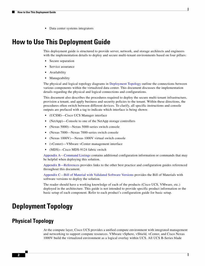
The physical and logical topology diagrams in Deployment Topology outline the connections between various components within the virtualized data center. This document discusses the implementation details regarding the physical and logical connections and configurations.
This document also describes the procedures required to deploy the secure multi-tenant infrastructure, provision a tenant, and apply business and security policies to the tenant. Within these directions, the procedures often switch between different devices. To clarify, all specific instructions and console outputs are prefaced with a tag to indicate which interface is being shown:
• (UCSM)—Cisco UCS Manager interface
• (NetApp)—Console to one of the NetApp storage controllers
• (Nexus 5000)—Nexus 5000-series switch console
• (Nexus 7000—Nexus 7000-series switch console
• (Nexus 1000V)—Nexus 1000V virtual switch console
• (vCenter)—VMware vCenter management interface
• (MDS)—Cisco MDS-9124 fabric switch
Appendix A—Command Listings contains additional configuration information or commands that may be helpful when deploying this solution.
Appendix B—References provides links to the other best practice and configuration guides referenced throughout this document.
Appendix C—Bill of Material with Validated Software Versions provides the Bill of Materials with software versions to deploy the solution.
The reader should have a working knowledge of each of the products (Cisco UCS, VMware, etc.) deployed in the architecture. This guide is not intended to provide specific product information or the basic setup of each component. Refer to each product’s configuration guide for basic setup.
Deployment Topology
Physical TopologyAt the compute layer, Cisco UCS provides a unified compute environment with integrated management and networking to support compute resources. VMware vSphere, vShield, vCenter, and Cisco Nexus 1000V build the virtualized environment as a logical overlay within UCS. All UCS B-Series blade
2
Deployment Topology
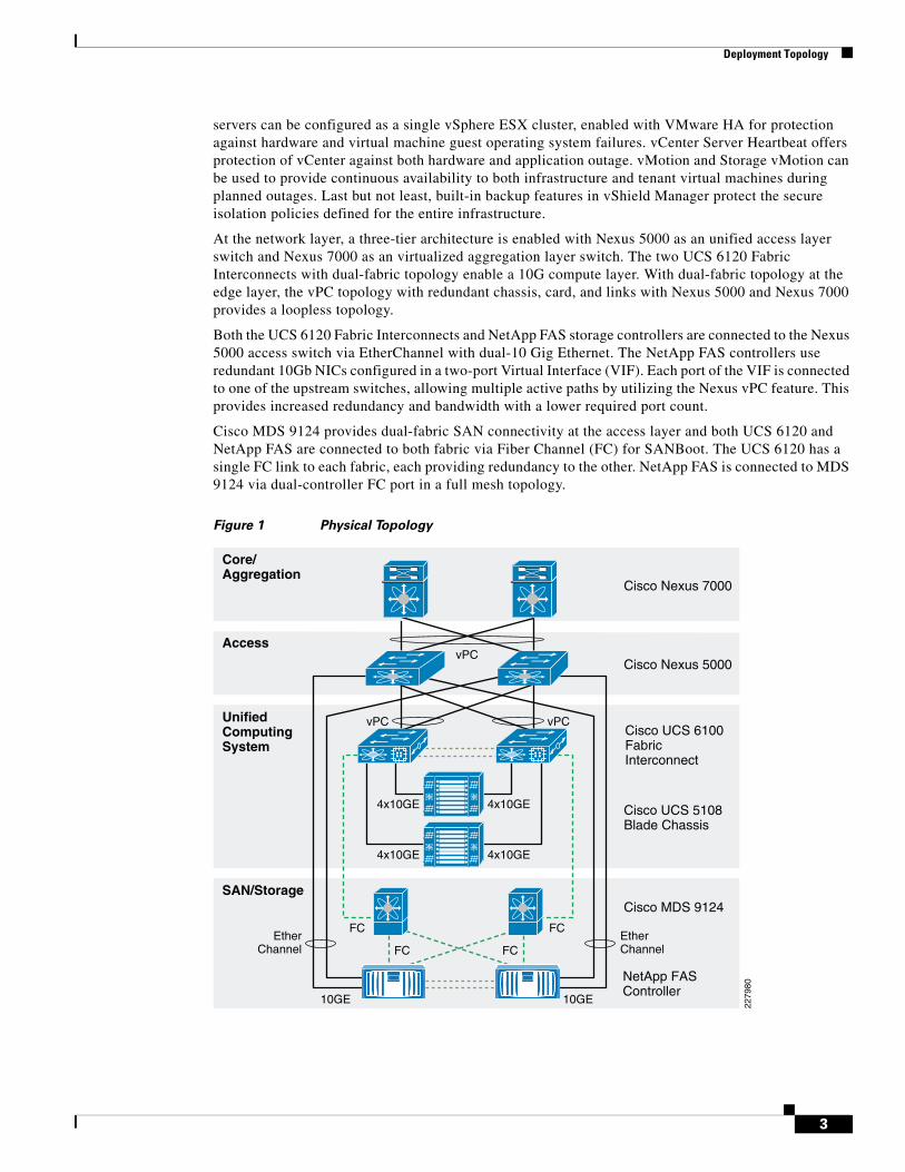
servers can be configured as a single vSphere ESX cluster, enabled with VMware HA for protection against hardware and virtual machine guest operating system failures. vCenter Server Heartbeat offers protection of vCenter against both hardware and application outage. vMotion and Storage vMotion can be used to provide continuous availability to both infrastructure and tenant virtual machines during planned outages. Last but not least, built-in backup features in vShield Manager protect the secure isolation policies defined for the entire infrastructure.
At the network layer, a three-tier architecture is enabled with Nexus 5000 as an unified access layer switch and Nexus 7000 as an virtualized aggregation layer switch. The two UCS 6120 Fabric Interconnects with dual-fabric topology enable a 10G compute layer. With dual-fabric topology at the edge layer, the vPC topology with redundant chassis, card, and links with Nexus 5000 and Nexus 7000 provides a loopless topology.
Both the UCS 6120 Fabric Interconnects and NetApp FAS storage controllers are connected to the Nexus 5000 access switch via EtherChannel with dual-10 Gig Ethernet. The NetApp FAS controllers use redundant 10Gb NICs configured in a two-port Virtual Interface (VIF). Each port of the VIF is connected to one of the upstream switches, allowing multiple active paths by utilizing the Nexus vPC feature. This provides increased redundancy and bandwidth with a lower required port count.
Cisco MDS 9124 provides dual-fabric SAN connectivity at the access layer and both UCS 6120 and NetApp FAS are connected to both fabric via Fiber Channel (FC) for SANBoot. The UCS 6120 has a single FC link to each fabric, each providing redundancy to the other. NetApp FAS is connected to MDS 9124 via dual-controller FC port in a full mesh topology.
Figure 1 Physical Topology
Core/Aggregation
Access
UnifiedComputingSystem
SAN/Storage
Cisco Nexus 7000
Cisco Nexus 5000
10GE
4x10GE
4x10GE
4x10GE
4x10GE
FC FC
vPC
vPCvPC
FC FCEtherChannel
EtherChannel
10GE
Cisco UCS 6100FabricInterconnect
Cisco UCS 5108Blade Chassis
Cisco MDS 9124
NetApp FASController
2279
80
3
Deployment Topology
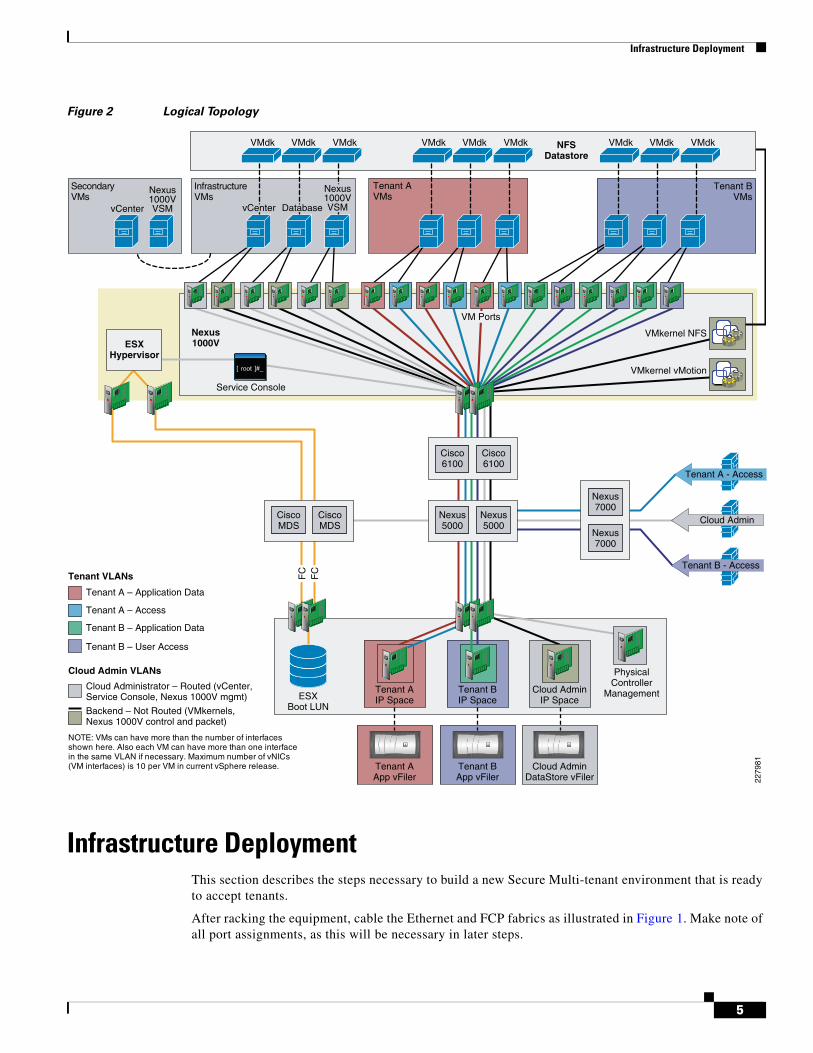
Logical TopologyThe logical topology represents the underlying virtual components and their virtual connections that exist within the physical topology.
The logical architecture consists of many virtual machines that fall into two categories, infrastructure and tenant. Infrastructure VMs are used in configuring and maintaining the environment, while tenant VMs are owned and leveraged by tenant applications and users. All VM configuration and disk files for both infrastructure and tenant VMs are stored in a shared NetApp virtual storage controller and are presented to each ESX host’s VMkernel interface as an NFS export.
Each VMware virtual interface type, Service Console, VMkernel, and individual VM interfaces connect directly to the Cisco Nexus 1000V software distributed virtual switch. At this layer, packets are tagged with the appropriate VLAN header and all outbound traffic is aggregated to the Cisco 6100 through two 10Gb Ethernet uplinks per ESX host. All inbound traffic is stripped of its VLAN header and switched to the appropriate destination virtual interface.
The two physical 10Gb Ethernet interfaces per physical NetApp storage controller are aggregated together into a single virtual interface. The virtual interface is further segmented into VLAN interfaces, with each VLAN interface corresponding to a specific VLAN ID throughout the topology. Each VLAN interface is administratively associated with a specific IP Space and vFiler unit. Each IP Space provides an individual IP routing table per vFiler unit. The association between a VLAN interface and a vFiler unit allows all outbound packets from the specific vFiler unit to be tagged with the appropriate VLAN ID specific to that VLAN interface. Accordingly, all inbound traffic with a specific VLAN ID is sent to the appropriate VLAN interface, effectively securing storage traffic, no matter what the Ethernet storage protocol, and allowing visibility to only the associated vFiler unit.
4
Infrastructure Deployment
Figure 2 Logical Topology
Infrastructure DeploymentThis section describes the steps necessary to build a new Secure Multi-tenant environment that is ready to accept tenants.
After racking the equipment, cable the Ethernet and FCP fabrics as illustrated in Figure 1. Make note of all port assignments, as this will be necessary in later steps.
Tenant A – Application Data
Tenant A – Access
Tenant B – Application Data
Tenant B – User Access
Cloud Admin VLANs
Tenant VLANs
Cloud Administrator – Routed (vCenter, Service Console, Nexus 1000V mgmt)
Backend – Not Routed (VMkernels,Nexus 1000V control and packet)
NOTE: VMs can have more than the number of interfacesshown here. Also each VM can have more than one interfacein the same VLAN if necessary. Maximum number of vNICs(VM interfaces) is 10 per VM in current vSphere release.
Tenant A - Access
Cloud Admin
Tenant B - Access
Nexus7000
Nexus7000
PhysicalController
Management
Nexus5000
Nexus5000
Cisco6100
Cisco6100
CiscoMDS
ESXBoot LUN
CiscoMDS
Tenant BIP Space
Cloud AdminIP Space
Tenant AIP Space
Tenant BApp vFiler
Cloud AdminDataStore vFiler
Tenant AApp vFiler
Tenant AVMs
Tenant BVMs
InfrastructureVMs
FAS3170FAS3170 FAS3170FAS3170 FAS3170FAS3170
FC
FC
ESXHypervisor
Nexus1000V
NFSDatastore
Service Console
VMkernel NFS
VMkernel vMotion
SecondaryVMs
VMdk VMdk VMdk VMdk VMdk VMdk VMdk VMdk VMdk
VM Ports
vCenter DatabasevCenter
Nexus1000VVSM
Nexus1000VVSM
2279
81
5
Infrastructure Deployment
Network Infrastructure ConnectivityThe network infrastructure deployment consists of the three tiers as described in the SMT design guide. The infrastructure deployment has adopted the best practices recommended in the following design guides and thus not all the configuration steps are described in this deployment guide, although exceptions and specific changes relevant to a SMT deployment are explained.
• DC 3.0 infrastructure: http://www.cisco.com/en/US/docs/solutions/Enterprise/Data_Center/DC_3_0/DC-3_0_IPInfra.html
• SAFE Design Guide: http://www.cisco.com/en/US/docs/solutions/Enterprise/Security/SAFE_RG/chap4.html
The network devices are connected as shown in Figure 1. The VLAN naming and configuration should be followed as per the design guide.
Configuring Logical Infrastructure Connectivity
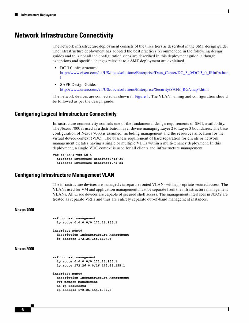
Infrastructure connectivity controls one of the fundamental design requirements of SMT, availability. The Nexus 7000 is used as a distribution layer device managing Layer 2 to Layer 3 boundaries. The base configuration of Nexus 7000 is assumed, including management and the resources allocation for the virtual device context (VDC). The business requirement of hard separation for clients or network management dictates having a single or multiple VDCs within a multi-tenancy deployment. In this deployment, a single VDC context is used for all clients and infrastructure management.
vdc sc-7k-1-vdc id 4 allocate interface Ethernet2/13-36 allocate interface Ethernet10/1-24
Configuring Infrastructure Management VLAN
The infrastructure devices are managed via separate routed VLANs with appropriate secured access. The VLANs used for VM and application management must be separate from the infrastructure management VLANs. All Cisco devices are capable of secured shell access. The management interfaces in NxOS are treated as separate VRFs and thus are entirely separate out-of-band management instances.
Nexus 7000
vrf context management ip route 0.0.0.0/0 172.26.155.1 interface mgmt0 description Infrastructure Management ip address 172.26.155.119/23
Nexus 5000
vrf context management ip route 0.0.0.0/0 172.26.155.1 ip route 172.26.0.0/16 172.26.155.1 interface mgmt0 description Infrastructure Management vrf member management no ip redirects ip address 172.26.155.193/23
6
Infrastructure Deployment
MDS 9216i
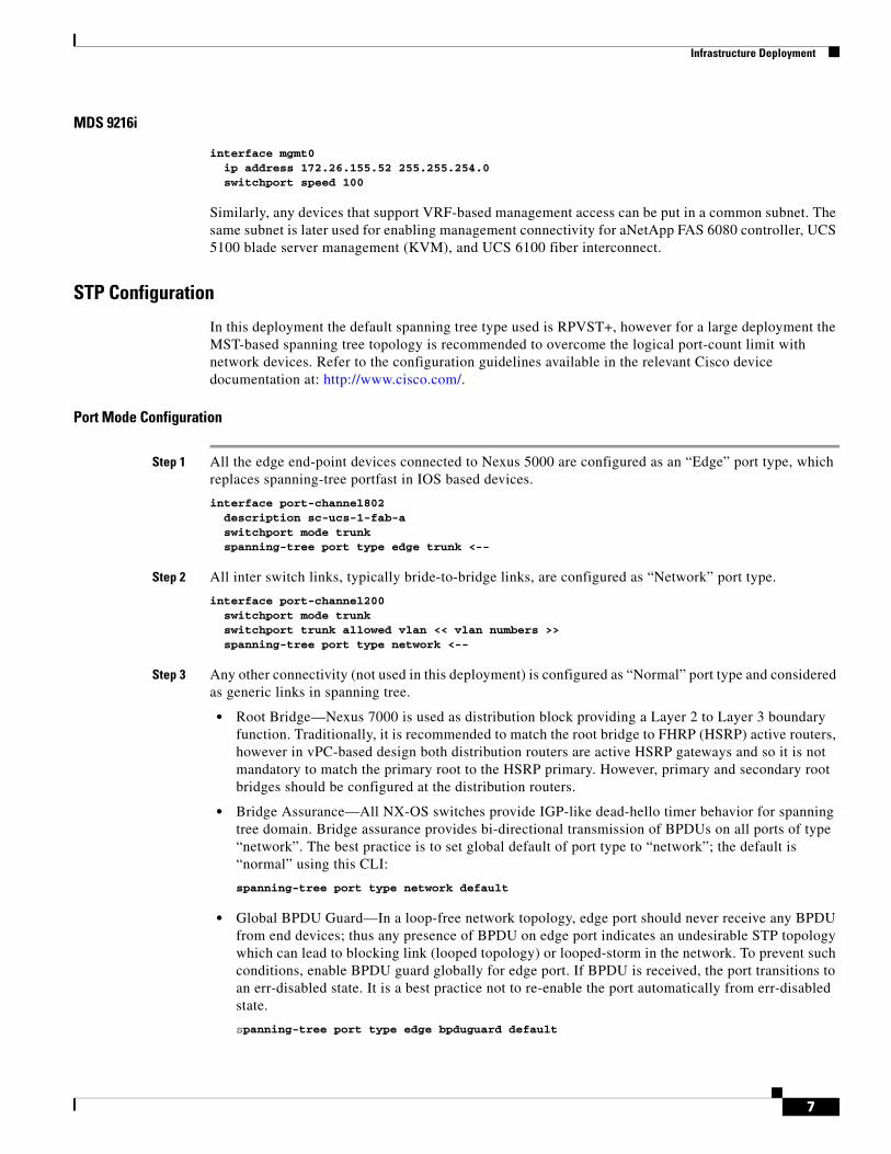
interface mgmt0 ip address 172.26.155.52 255.255.254.0 switchport speed 100
Similarly, any devices that support VRF-based management access can be put in a common subnet. The same subnet is later used for enabling management connectivity for aNetApp FAS 6080 controller, UCS 5100 blade server management (KVM), and UCS 6100 fiber interconnect.
STP Configuration
In this deployment the default spanning tree type used is RPVST+, however for a large deployment the MST-based spanning tree topology is recommended to overcome the logical port-count limit with network devices. Refer to the configuration guidelines available in the relevant Cisco device documentation at: http://www.cisco.com/.
Port Mode Configuration
Step 1 All the edge end-point devices connected to Nexus 5000 are configured as an “Edge” port type, which replaces spanning-tree portfast in IOS based devices.
interface port-channel802 description sc-ucs-1-fab-a switchport mode trunk spanning-tree port type edge trunk <--
Step 2 All inter switch links, typically bride-to-bridge links, are configured as “Network” port type.
interface port-channel200 switchport mode trunk switchport trunk allowed vlan << vlan numbers >> spanning-tree port type network <--
Step 3 Any other connectivity (not used in this deployment) is configured as “Normal” port type and considered as generic links in spanning tree.
• Root Bridge—Nexus 7000 is used as distribution block providing a Layer 2 to Layer 3 boundary function. Traditionally, it is recommended to match the root bridge to FHRP (HSRP) active routers, however in vPC-based design both distribution routers are active HSRP gateways and so it is not mandatory to match the primary root to the HSRP primary. However, primary and secondary root bridges should be configured at the distribution routers.
• Bridge Assurance—All NX-OS switches provide IGP-like dead-hello timer behavior for spanning tree domain. Bridge assurance provides bi-directional transmission of BPDUs on all ports of type “network”. The best practice is to set global default of port type to “network”; the default is “normal” using this CLI:
spanning-tree port type network default
• Global BPDU Guard—In a loop-free network topology, edge port should never receive any BPDU from end devices; thus any presence of BPDU on edge port indicates an undesirable STP topology which can lead to blocking link (looped topology) or looped-storm in the network. To prevent such conditions, enable BPDU guard globally for edge port. If BPDU is received, the port transitions to an err-disabled state. It is a best practice not to re-enable the port automatically from err-disabled state.
spanning-tree port type edge bpduguard default
7
Infrastructure Deployment
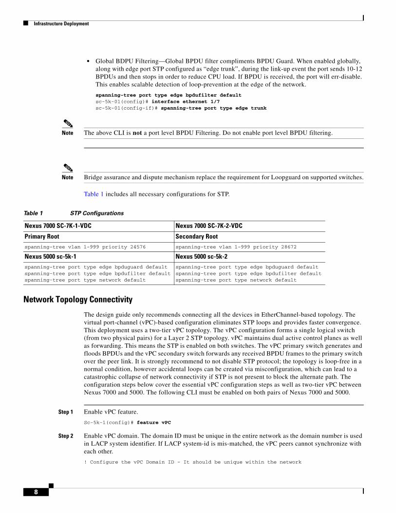
• Global BDPU Filtering—Global BPDU filter compliments BPDU Guard. When enabled globally, along with edge port STP configured as “edge trunk”, during the link-up event the port sends 10-12 BPDUs and then stops in order to reduce CPU load. If BPDU is received, the port will err-disable. This enables scalable detection of loop-prevention at the edge of the network.
spanning-tree port type edge bpdufilter defaultsc-5k-01(config)# interface ethernet 1/7sc-5k-01(config-if)# spanning-tree port type edge trunk
Note The above CLI is not a port level BPDU Filtering. Do not enable port level BPDU filtering.
Note Bridge assurance and dispute mechanism replace the requirement for Loopguard on supported switches.
Table 1 includes all necessary configurations for STP.
Network Topology Connectivity
The design guide only recommends connecting all the devices in EtherChannel-based topology. The virtual port-channel (vPC)-based configuration eliminates STP loops and provides faster convergence. This deployment uses a two-tier vPC topology. The vPC configuration forms a single logical switch (from two physical pairs) for a Layer 2 STP topology. vPC maintains dual active control planes as well as forwarding. This means the STP is enabled on both switches. The vPC primary switch generates and floods BPDUs and the vPC secondary switch forwards any received BPDU frames to the primary switch over the peer link. It is strongly recommend to not disable STP protocol; the topology is loop-free in a normal condition, however accidental loops can be created via misconfiguration, which can lead to a catastrophic collapse of network connectivity if STP is not present to block the alternate path. The configuration steps below cover the essential vPC configuration steps as well as two-tier vPC between Nexus 7000 and 5000. The following CLI must be enabled on both pairs of Nexus 7000 and 5000.
Step 1 Enable vPC feature.
Sc-5k-1(config)# feature vPC
Step 2 Enable vPC domain. The domain ID must be unique in the entire network as the domain number is used in LACP system identifier. If LACP system-id is mis-matched, the vPC peers cannot synchronize with each other.
! Configure the vPC Domain ID - It should be unique within the network
Table 1 STP Configurations
Nexus 7000 SC-7K-1-VDC Nexus 7000 SC-7K-2-VDC
Primary Root Secondary Rootspanning-tree vlan 1-999 priority 24576 spanning-tree vlan 1-999 priority 28672
Nexus 5000 sc-5k-1 Nexus 5000 sc-5k-2
spanning-tree port type edge bpduguard defaultspanning-tree port type edge bpdufilter defaultspanning-tree port type network default
spanning-tree port type edge bpduguard defaultspanning-tree port type edge bpdufilter defaultspanning-tree port type network default
8
Infrastructure Deployment
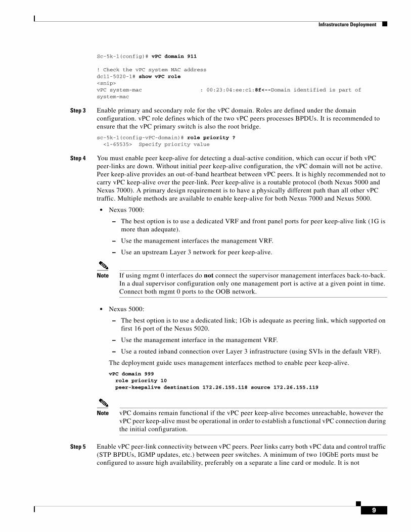
Sc-5k-1(config)# vPC domain 911 ! Check the vPC system MAC address dc11-5020-1# show vPC role <snip> vPC system-mac : 00:23:04:ee:c1:8f<--Domain identified is part of system-mac
Step 3 Enable primary and secondary role for the vPC domain. Roles are defined under the domain configuration. vPC role defines which of the two vPC peers processes BPDUs. It is recommended to ensure that the vPC primary switch is also the root bridge.
sc-5k-1(config-vPC-domain)# role priority ? <1-65535> Specify priority value
Step 4 You must enable peer keep-alive for detecting a dual-active condition, which can occur if both vPC peer-links are down. Without initial peer keep-alive configuration, the vPC domain will not be active. Peer keep-alive provides an out-of-band heartbeat between vPC peers. It is highly recommended not to carry vPC keep-alive over the peer-link. Peer keep-alive is a routable protocol (both Nexus 5000 and Nexus 7000). A primary design requirement is to have a physically different path than all other vPC traffic. Multiple methods are available to enable keep-alive for both Nexus 7000 and Nexus 5000.
• Nexus 7000:
– The best option is to use a dedicated VRF and front panel ports for peer keep-alive link (1G is more than adequate).
– Use the management interfaces the management VRF.
– Use an upstream Layer 3 network for peer keep-alive.
Note If using mgmt 0 interfaces do not connect the supervisor management interfaces back-to-back. In a dual supervisor configuration only one management port is active at a given point in time. Connect both mgmt 0 ports to the OOB network.
• Nexus 5000:
– The best option is to use a dedicated link; 1Gb is adequate as peering link, which supported on first 16 port of the Nexus 5020.
– Use the management interface in the management VRF.
– Use a routed inband connection over Layer 3 infrastructure (using SVIs in the default VRF).
The deployment guide uses management interfaces method to enable peer keep-alive.
vPC domain 999 role priority 10 peer-keepalive destination 172.26.155.118 source 172.26.155.119
Note vPC domains remain functional if the vPC peer keep-alive becomes unreachable, however the vPC peer keep-alive must be operational in order to establish a functional vPC connection during the initial configuration.
Step 5 Enable vPC peer-link connectivity between vPC peers. Peer links carry both vPC data and control traffic (STP BPDUs, IGMP updates, etc.) between peer switches. A minimum of two 10GbE ports must be configured to assure high availability, preferably on a separate a line card or module. It is not
9
Infrastructure Deployment
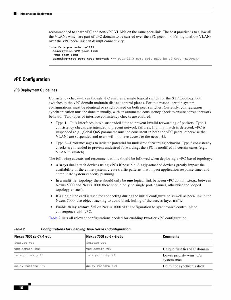
recommended to share vPC and non-vPC VLANs on the same peer-link. The best practice is to allow all the VLANs which are part of vPC domain to be carried over the vPC peer-link. Failing to allow VLANs over the vPC peer-link can disrupt connectivity.
interface port-channel911 description vPC peer-link vpc peer-link spanning-tree port type network <-- peer-link port role must be of type "network"
vPC Configuration
vPC Deployment Guidelines
Consistency check—Even though vPC enables a single logical switch for the STP topology, both switches in the vPC domain maintain distinct control planes. For this reason, certain system configurations must be identical or synchronized on both peer switches. Currently, configuration synchronization must be done manually, with an automated consistency check to ensure correct network behavior. Two types of interface consistency checks are enabled:
• Type 1—Puts interfaces into a suspended state to prevent invalid forwarding of packets. Type 1 consistency checks are intended to prevent network failures. If a mis-match is detected, vPC is suspended (e.g., global QoS parameter must be consistent in both the vPC peers, otherwise the VLANs are suspended and users will not have access to the network).
• Type 2—Error messages to indicate potential for undesired forwarding behavior. Type 2 consistency checks are intended to prevent undesired forwarding; the vPC is modified in certain cases (e.g., VLAN mismatch).
The following caveats and recommendations should be followed when deploying a vPC-based topology:
• Always dual attach devices using vPCs if possible. Singly-attached devices greatly impact the availability of the entire system, create traffic patterns that impact application response time, and complicate system capacity planning.
• In a multi-tier topology there should only be one logical link between vPC domains.(e.g., between Nexus 5000 and Nexus 7000 there should only be single port-channel, otherwise the looped topology ensues).
• If a single line card is used for connecting during the initial configuration as well as peer-link in the Nexus 7000, use object tracking to avoid black-holing of the access-layer traffic.
• Enable delay restore 360 on Nexus 7000 vPC configuration to synchronize control plane convergence with vPC.
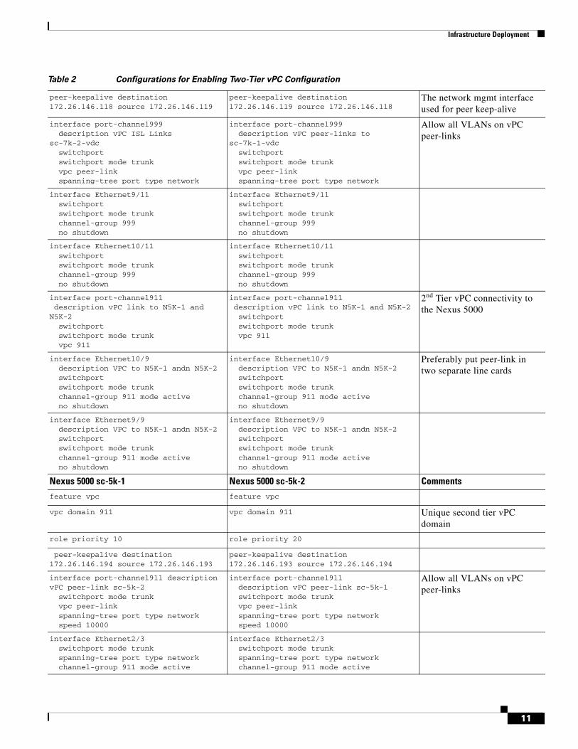
Table 2 lists all relevant configurations needed for enabling two-tier vPC configuration.
Table 2 Configurations for Enabling Two-Tier vPC Configuration
Nexus 7000 sc-7k-1-vdc Nexus 7000 sc-7k-2-vdc Comments
feature vpc feature vpc
vpc domain 900 vpc domain 900 Unique first tier vPC domain
role priority 10 role priority 20 Lower priority wins, o/w system-mac
delay restore 360 delay restore 360 Delay for synchronization
10
Infrastructure Deployment
peer-keepalive destination 172.26.146.118 source 172.26.146.119
peer-keepalive destination 172.26.146.119 source 172.26.146.118
The network mgmt interface used for peer keep-alive
interface port-channel999 description vPC ISL Links sc-7k-2-vdc switchport switchport mode trunk vpc peer-link spanning-tree port type network
interface port-channel999 description vPC peer-links to sc-7k-1-vdc switchport switchport mode trunk vpc peer-link spanning-tree port type network
Allow all VLANs on vPC peer-links
interface Ethernet9/11 switchport switchport mode trunk channel-group 999 no shutdown
interface Ethernet9/11 switchport switchport mode trunk channel-group 999 no shutdown
interface Ethernet10/11 switchport switchport mode trunk channel-group 999 no shutdown
interface Ethernet10/11 switchport switchport mode trunk channel-group 999 no shutdown
interface port-channel911 description vPC link to N5K-1 and N5K-2 switchport switchport mode trunk vpc 911
interface port-channel911 description vPC link to N5K-1 and N5K-2 switchport switchport mode trunk vpc 911
2nd Tier vPC connectivity to the Nexus 5000
interface Ethernet10/9 description VPC to N5K-1 andn N5K-2 switchport switchport mode trunk channel-group 911 mode active no shutdown
interface Ethernet10/9 description VPC to N5K-1 andn N5K-2 switchport switchport mode trunk channel-group 911 mode active no shutdown
Preferably put peer-link in two separate line cards
interface Ethernet9/9 description VPC to N5K-1 andn N5K-2 switchport switchport mode trunk channel-group 911 mode active no shutdown
interface Ethernet9/9 description VPC to N5K-1 andn N5K-2 switchport switchport mode trunk channel-group 911 mode active no shutdown
Nexus 5000 sc-5k-1 Nexus 5000 sc-5k-2 Comments
feature vpc feature vpc
vpc domain 911 vpc domain 911 Unique second tier vPC domain
role priority 10 role priority 20
peer-keepalive destination 172.26.146.194 source 172.26.146.193
peer-keepalive destination 172.26.146.193 source 172.26.146.194
interface port-channel911 description vPC peer-link sc-5k-2 switchport mode trunk vpc peer-link spanning-tree port type network speed 10000
interface port-channel911 description vPC peer-link sc-5k-1 switchport mode trunk vpc peer-link spanning-tree port type network speed 10000
Allow all VLANs on vPC peer-links
interface Ethernet2/3 switchport mode trunk spanning-tree port type network channel-group 911 mode active
interface Ethernet2/3 switchport mode trunk spanning-tree port type network channel-group 911 mode active
Table 2 Configurations for Enabling Two-Tier vPC Configuration
11
Infrastructure Deployment
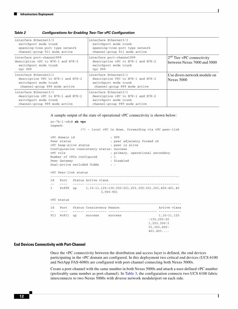
A sample output of the state of operational vPC connectivity is shown below:
sc-7k-1-vdc# sh vpc Legend: (*) - local vPC is down, forwarding via vPC peer-link vPC domain id : 999 Peer status : peer adjacency formed ok vPC keep-alive status : peer is alive Configuration consistency status: success vPC role : primary, operational secondary Number of vPCs configured : 1 Peer Gateway : Disabled Dual-active excluded VLANs : - vPC Peer-link status --------------------------------------------------------------------- id Port Status Active vlans -- ---- ------ -------------------------------------------------- 1 Po999 up 1,10-11,125-130,200-201,203,300-301,303,400-401,40 3,900-901 vPC status ---------------------------------------------------------------------- id Port Status Consistency Reason Active vlans -- ---- ------ ----------- -------------------------- ------------ 911 Po911 up success success 1,10-11,125
-130,200-20 1,203,300-3 01,303,400- 401,403....
End Devices Connectivity with Port-Channel
Once the vPC connectivity between the distribution and access layer is defined, the end devices participating in the vPC domain are configured. In this deployment two critical end devices (UCS 6100 and NetApp FAS-6080) are configured with port-channel connecting both Nexus 5000s.
Create a port-channel with the same number in both Nexus 5000s and attach a user-defined vPC number (preferably same number as port-channel). In Table 3, the configuration connects two UCS 6100 fabric interconnects to two Nexus 5000s with diverse network module/port on each side.
interface Ethernet3/3 switchport mode trunk spanning-tree port type network channel-group 911 mode active
interface Ethernet3/3 switchport mode trunk spanning-tree port type network channel-group 911 mode active
interface port-channel999description vPC to N7K-1 and N7K-2 switchport mode trunk vpc 999
interface port-channel999 description vPC to N7K-1 and N7K-2 switchport mode trunk vpc 999
2nd Tier vPC connectivity between Nexus 7000 and 5000
interface Ethernet2/1 description VPC to N7K-1 and N7K-2 switchport mode trunk channel-group 999 mode active
interface Ethernet2/1 description VPC to N7K-1 and N7K-2 switchport mode trunk channel-group 999 mode active
Use divers network module on Nexus 5000
interface Ethernet3/1 description vPC to N7K-1 and N7K-2 switchport mode trunk channel-group 999 mode active
interface Ethernet3/1 description vPC to N7K-1 and N7K-2 switchport mode trunk channel-group 999 mode active
Table 2 Configurations for Enabling Two-Tier vPC Configuration
12
Infrastructure Deployment
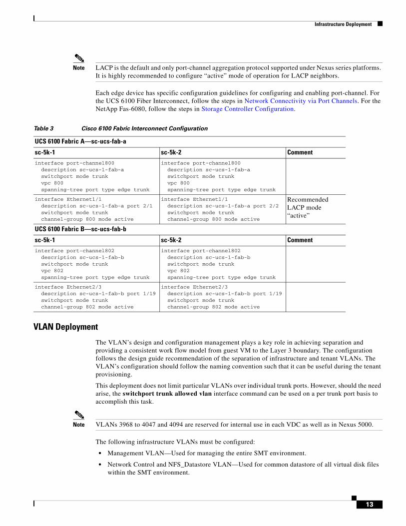
Note LACP is the default and only port-channel aggregation protocol supported under Nexus series platforms. It is highly recommended to configure “active” mode of operation for LACP neighbors.
Each edge device has specific configuration guidelines for configuring and enabling port-channel. For the UCS 6100 Fiber Interconnect, follow the steps in Network Connectivity via Port Channels. For the NetApp Fas-6080, follow the steps in Storage Controller Configuration.
VLAN Deployment
The VLAN’s design and configuration management plays a key role in achieving separation and providing a consistent work flow model from guest VM to the Layer 3 boundary. The configuration follows the design guide recommendation of the separation of infrastructure and tenant VLANs. The VLAN’s configuration should follow the naming convention such that it can be useful during the tenant provisioning.
This deployment does not limit particular VLANs over individual trunk ports. However, should the need arise, the switchport trunk allowed vlan interface command can be used on a per trunk port basis to accomplish this task.
Note VLANs 3968 to 4047 and 4094 are reserved for internal use in each VDC as well as in Nexus 5000.
The following infrastructure VLANs must be configured:
• Management VLAN—Used for managing the entire SMT environment.
• Network Control and NFS_Datastore VLAN—Used for common datastore of all virtual disk files within the SMT environment.
Table 3 Cisco 6100 Fabric Interconnect Configuration
UCS 6100 Fabric A—sc-ucs-fab-a
sc-5k-1 sc-5k-2 Comment
interface port-channel800 description sc-ucs-1-fab-a switchport mode trunk vpc 800 spanning-tree port type edge trunk
interface port-channel800 description sc-ucs-1-fab-a switchport mode trunk vpc 800 spanning-tree port type edge trunk
interface Ethernet1/1 description sc-ucs-1-fab-a port 2/1 switchport mode trunk channel-group 800 mode active
interface Ethernet1/1 description sc-ucs-1-fab-a port 2/2 switchport mode trunk channel-group 800 mode active
Recommended LACP mode “active”
UCS 6100 Fabric B—sc-ucs-fab-b
sc-5k-1 sc-5k-2 Comment
interface port-channel802 description sc-ucs-1-fab-b switchport mode trunk vpc 802 spanning-tree port type edge trunk
interface port-channel802 description sc-ucs-1-fab-b switchport mode trunk vpc 802 spanning-tree port type edge trunk
interface Ethernet2/3 description sc-ucs-1-fab-b port 1/19 switchport mode trunk channel-group 802 mode active
interface Ethernet2/3 description sc-ucs-1-fab-b port 1/19 switchport mode trunk channel-group 802 mode active
13
Infrastructure Deployment
• vMotion VLAN—Used for migrating VMs between ESX hosts within the SMT environment.
Configuring Infrastructure Management VLAN
This VLAN is designed to be routed and centrally administered. This also means all the security policies for the VLAN be applied based on providing access to only the administrator of the SMT environment. The following types of traffic and connectivity are managed by the infrastructure management VLAN:
• All the console connectivity of network devices (Nexus 7000, Nexus 5000, MDS 9216i)
• GUI and SSH access to NetApp controller
• UCS 6100 (both individual and cluster) and KVM address for each blades
• Console interface (vswif) for each ESX server
• Any infrastructure appliances and virtual machine, e.g., Nexus 1000V management, vShield, etc.
The following defines the routed VLAN in both Nexus 5000 and Nexus 7000:
vlan 155 name VM_Con-N1kV-Mgmt_172_26_155
The following is required for defining default gateway redundancy:
HSRP primary configuration:
interface Vlan155 no shutdown ip address 172.26.155.0.3/22 hsrp 1 authentication text c1sco preempt delay minimum 180 reload 180 timers 1 3 ip 172.26.155.1
HSRP secondary configuration:
interface Vlan155 no shutdown ip address 172.26.155.0.3/22 hsrp 1 authentication text c1sco preempt delay minimum 180 reload 180 priority 10 timers 1 3 ip 172.26.155.1
Configuring Network Control Plane and NFS Datastore VLAN
This VLAN is not a routed VLAN, however for troubleshooting and operational requirements it is strongly recommended to have a host (which can function as SNMP relay) with IP connectivity to any non-routed VLAN. Without an independent IP device it is extremely hard to verify individual resource connectivity and SNMP management. This VLAN consolidates the following functionalities into a single VLAN:
• NFS datastore traffic
• Nexus 1000V Control traffic
• Nexus 1000V Packet traffic
14
Infrastructure Deployment
The NFS datastore VLAN is configured to provide IP communication between each ESX host’s VMkernel interface and the infrastructure vfiler containing the NFS export. Nexus 1000V control traffic is a Layer 2 communication between the Virtual Supervisor Module (VSM) and the Virtual Ethernet Module residing in each ESX sever and therefore does not require IP addressing.
vlan 900 name NFS_DataStore-N1K-CtrPkt_100_100
The configuration steps on the Nexus 1000V are described in Nexus 1000V Configuration once the UCS and ESX server configuration steps are completed.
Configuring vMotion VLAN
The vMotion VLAN is not routed and configured with separate VMkernel interface on each ESX sever.
vlan 901 name VMotion_10_100_102
Monitoring VLAN
This VLAN is used for monitoring as well ERSPAN and SPAN functionality:
vlan 902 name Remote_Span
Storage Controller ConfigurationRefer to TR-3649, Best Practices for Secure Configuration of Data ONTAP 7G, for additional security configuration of the NetApp storage controller: http://media.netapp.com/documents/tr-3649.pdf.
Step 1 Referring to the NetApp Installation and Setup Instructions (available at: http://now.netapp.com/NOW/knowledge/docs/hardware/hardware_index.shtml), configure the two storage controllers as an HA pair, ensuring that disk shelves are properly connected and that the two controllers are linked with an HA cluster cable. Each controller should have a dual-port 10Gb NIC cabled as indicated in Figure 1.
Step 2 Referring to the Active/Active Configuration Guide (available at: http://now.netapp.com/NOW/knowledge/docs/ontap/rel732/), boot the controllers into maintenance mode and configure disk ownership appropriately. Ensure that the controllers are running Data ONTAP version 7.3.2 (see the Upgrade Guide for details on upgrading).
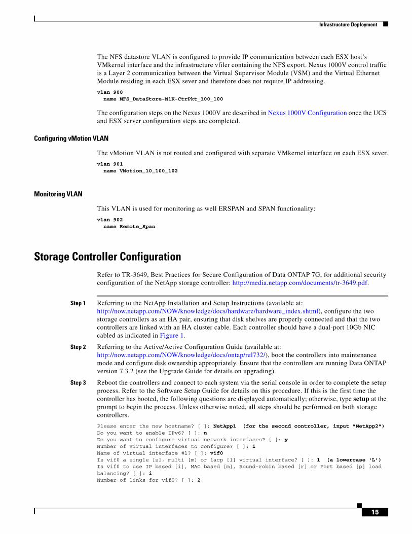
Step 3 Reboot the controllers and connect to each system via the serial console in order to complete the setup process. Refer to the Software Setup Guide for details on this procedure. If this is the first time the controller has booted, the following questions are displayed automatically; otherwise, type setup at the prompt to begin the process. Unless otherwise noted, all steps should be performed on both storage controllers.
Please enter the new hostname? [ ]: NetApp1 (for the second controller, input "NetApp2") Do you want to enable IPv6? [ ]: n Do you want to configure virtual network interfaces? [ ]: y Number of virtual interfaces to configure? [ ]: 1 Name of virtual interface #1? [ ]: vif0 Is vif0 a single [s], multi [m] or lacp [l] virtual interface? [ ]: l (a lowercase 'L') Is vif0 to use IP based [i], MAC based [m], Round-robin based [r] or Port based [p] load balancing? [ ]: i Number of links for vif0? [ ]: 2
15
Infrastructure Deployment
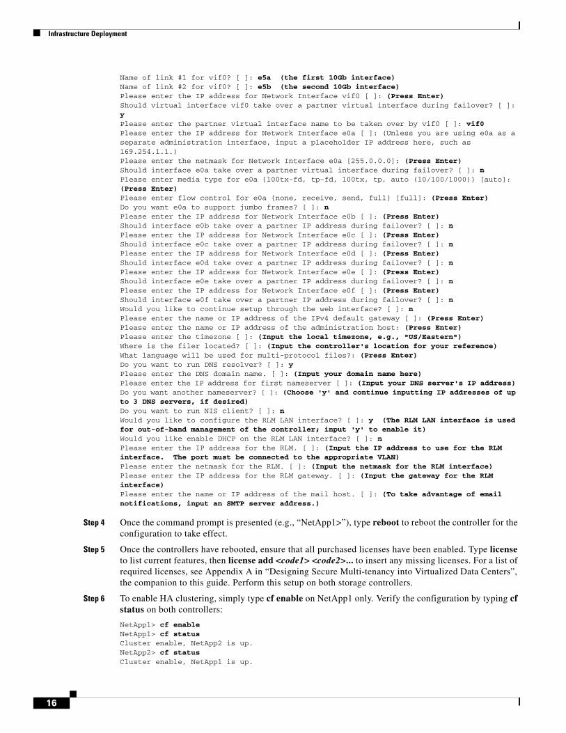
Name of link #1 for vif0? [ ]: e5a (the first 10Gb interface) Name of link #2 for vif0? [ ]: e5b (the second 10Gb interface) Please enter the IP address for Network Interface vif0 [ ]: (Press Enter) Should virtual interface vif0 take over a partner virtual interface during failover? [ ]: y Please enter the partner virtual interface name to be taken over by vif0 [ ]: vif0 Please enter the IP address for Network Interface e0a [ ]: (Unless you are using e0a as a separate administration interface, input a placeholder IP address here, such as 169.254.1.1.) Please enter the netmask for Network Interface e0a [255.0.0.0]: (Press Enter) Should interface e0a take over a partner virtual interface during failover? [ ]: n Please enter media type for e0a {100tx-fd, tp-fd, 100tx, tp, auto (10/100/1000)} [auto]: (Press Enter) Please enter flow control for e0a {none, receive, send, full} [full]: (Press Enter) Do you want e0a to support jumbo frames? [ ]: n Please enter the IP address for Network Interface e0b [ ]: (Press Enter) Should interface e0b take over a partner IP address during failover? [ ]: n Please enter the IP address for Network Interface e0c [ ]: (Press Enter) Should interface e0c take over a partner IP address during failover? [ ]: n Please enter the IP address for Network Interface e0d [ ]: (Press Enter) Should interface e0d take over a partner IP address during failover? [ ]: n Please enter the IP address for Network Interface e0e [ ]: (Press Enter) Should interface e0e take over a partner IP address during failover? [ ]: n Please enter the IP address for Network Interface e0f [ ]: (Press Enter) Should interface e0f take over a partner IP address during failover? [ ]: n Would you like to continue setup through the web interface? [ ]: n Please enter the name or IP address of the IPv4 default gateway [ ]: (Press Enter) Please enter the name or IP address of the administration host: (Press Enter) Please enter the timezone [ ]: (Input the local timezone, e.g., "US/Eastern") Where is the filer located? [ ]: (Input the controller's location for your reference) What language will be used for multi-protocol files?: (Press Enter) Do you want to run DNS resolver? [ ]: y Please enter the DNS domain name. [ ]: (Input your domain name here) Please enter the IP address for first nameserver [ ]: (Input your DNS server's IP address) Do you want another nameserver? [ ]: (Choose 'y' and continue inputting IP addresses of up to 3 DNS servers, if desired) Do you want to run NIS client? [ ]: n Would you like to configure the RLM LAN interface? [ ]: y (The RLM LAN interface is used for out-of-band management of the controller; input 'y' to enable it) Would you like enable DHCP on the RLM LAN interface? [ ]: n Please enter the IP address for the RLM. [ ]: (Input the IP address to use for the RLM interface. The port must be connected to the appropriate VLAN) Please enter the netmask for the RLM. [ ]: (Input the netmask for the RLM interface) Please enter the IP address for the RLM gateway. [ ]: (Input the gateway for the RLM interface) Please enter the name or IP address of the mail host. [ ]: (To take advantage of email notifications, input an SMTP server address.)
Step 4 Once the command prompt is presented (e.g., “NetApp1>”), type reboot to reboot the controller for the configuration to take effect.
Step 5 Once the controllers have rebooted, ensure that all purchased licenses have been enabled. Type license to list current features, then license add <code1> <code2>... to insert any missing licenses. For a list of required licenses, see Appendix A in “Designing Secure Multi-tenancy into Virtualized Data Centers”, the companion to this guide. Perform this setup on both storage controllers.
Step 6 To enable HA clustering, simply type cf enable on NetApp1 only. Verify the configuration by typing cf status on both controllers:
NetApp1> cf enable NetApp1> cf status Cluster enable, NetApp2 is up. NetApp2> cf status Cluster enable, NetApp1 is up.
16
Infrastructure Deployment
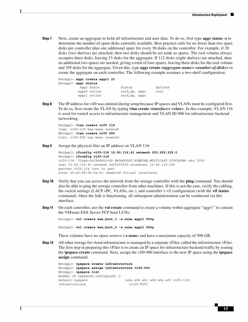
Step 7 Next, create an aggregate to hold all infrastructure and user data. To do so, first type aggr status -s to determine the number of spare disks currently available. Best practice calls for no fewer than two spare disks per controller plus one additional spare for every 56 disks on the controller. For example, if 28 disks (two shelves) are attached, then two disks should be set aside as spares. The root volume always occupies three disks, leaving 23 disks for the aggregate. If 112 disks (eight shelves) are attached, then an additional two spares are needed, giving a total of four spares, leaving three disks for the root volume and 105 disks for the aggregate. Given this, type aggr create <aggregate-name> <number-of-disks> to create the aggregate on each controller. The following example assumes a two-shelf configuration:
NetApp1> aggr create aggr1 23 NetApp1> aggr status Aggr State Status Options aggr0 online raid_dp, aggr root aggr1 online raid_dp, aggr
Step 8 The IP address for vif0 was omitted during setup because IP spaces and VLANs must be configured first. To do so, first create the VLAN by typing vlan create <interface> <vlan>. In this example, VLAN 116 is used for routed access to infrastructure management and VLAN ID 900 for infrastructure backend networking.
NetApp1> vlan create vif0 116 vlan: vif0-116 has been created NetApp1> vlan create vif0 900 vlan: vif0-900 has been created
Step 9 Assign the physical filer an IP address on VLAN 116:
NetApp1> ifconfig vif0-116 10.60.116.41 netmask 255.255.255.0 NetApp1> ifconfig vif0-116 vif0-116: flags=0x3948863<UP,BROADCAST,RUNNING,MULTICAST,TCPCKSUM> mtu 1500 inet 10.60.116.41 netmask 0xffffff00 broadcast 10.60.116.255 partner vif0-116 (not in use) ether 02:a0:98:08:6a:0c (Enabled virtual interface)
Step 10 Verify that you can access the network from the storage controller with the ping command. You should also be able to ping the storage controller from other machines. If this is not the case, verify the cabling, the switch settings (LACP vPC, VLANs, etc.), and controller’s vif configuration (with the vif status command). Once the link is functioning, all subsequent administration can be conducted via this interface.
Step 11 On each controller, use the vol create command to create a volume within aggregate “aggr1” to contain the VMware ESX Server FCP boot LUNs:
NetApp1> vol create esx_boot_1 -s none aggr1 500g
NetApp2> vol create esx_boot_2 -s none aggr1 500g
These volumes have no space reserve (-s none) and have a maximum capacity of 500 GB.
Step 12 All other storage for cloud infrastructure is managed by a separate vFiler, called the infrastructure vFiler. The first step in preparing this vFiler is to create an IP space for infrastructure backend traffic by issuing the ipspace create command. Next, assign the vif0-900 interface to the new IP space using the ipspace assign command:
NetApp1> ipspace create infrastructure NetApp1> ipspace assign infrastructure vif0-900 NetApp1> ipspace list Number of ipspaces configured: 2 default-ipspace (e0a e0b e0c e0d e0e e0f vif0-116) infrastructure (vif0-900)
17
Infrastructure Deployment
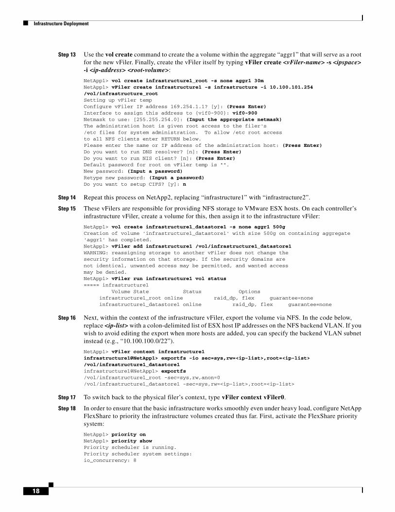
Step 13 Use the vol create command to create the a volume within the aggregate “aggr1” that will serve as a root for the new vFiler. Finally, create the vFiler itself by typing vFiler create <vFiler-name> -s <ipspace> -i <ip-address> <root-volume>:
NetApp1> vol create infrastructure1_root -s none aggr1 30mNetApp1> vFiler create infrastructure1 -s infrastructure -i 10.100.101.254 /vol/infrastructure_root Setting up vFiler temp Configure vFiler IP address 169.254.1.1? [y]: (Press Enter) Interface to assign this address to {vif0-900}: vif0-900 Netmask to use: [255.255.254.0]: (Input the appropriate netmask) The administration host is given root access to the filer's /etc files for system administration. To allow /etc root access to all NFS clients enter RETURN below. Please enter the name or IP address of the administration host: (Press Enter) Do you want to run DNS resolver? [n]: (Press Enter) Do you want to run NIS client? [n]: (Press Enter) Default password for root on vFiler temp is "". New password: (Input a password) Retype new password: (Input a password) Do you want to setup CIFS? [y]: n
Step 14 Repeat this process on NetApp2, replacing “infrastructure1” with “infrastructure2”.
Step 15 These vFilers are responsible for providing NFS storage to VMware ESX hosts. On each controller’s infrastructure vFiler, create a volume for this, then assign it to the infrastructure vFiler:
NetApp1> vol create infrastructure1_datastore1 -s none aggr1 500g Creation of volume 'infrastructure1_datastore1' with size 500g on containing aggregate 'aggr1' has completed. NetApp1> vFiler add infrastructure1 /vol/infrastructure1_datastore1 WARNING: reassigning storage to another vFiler does not change the security information on that storage. If the security domains are not identical, unwanted access may be permitted, and wanted access may be denied. NetApp1> vFiler run infrastructure1 vol status ===== infrastructure1 Volume State Status Options infrastructure1_root online raid_dp, flex guarantee=none infrastructure1_datastore1 online raid_dp, flex guarantee=none
Step 16 Next, within the context of the infrastructure vFiler, export the volume via NFS. In the code below, replace <ip-list> with a colon-delimited list of ESX host IP addresses on the NFS backend VLAN. If you wish to avoid editing the export when more hosts are added, you can specify the backend VLAN subnet instead (e.g., “10.100.100.0/22”).
NetApp1> vFiler context infrastructure1 infrastructure1@NetApp1> exportfs -io sec=sys,rw=<ip-list>,root=<ip-list> /vol/infrastructure1_datastore1 infrastructure1@NetApp1> exportfs /vol/infrastructure1_root -sec=sys,rw,anon=0 /vol/infrastructure1_datastore1 -sec=sys,rw=<ip-list>,root=<ip-list>
Step 17 To switch back to the physical filer’s context, type vFiler context vFiler0.
Step 18 In order to ensure that the basic infrastructure works smoothly even under heavy load, configure NetApp FlexShare to priority the infrastructure volumes created thus far. First, activate the FlexShare priority system:
NetApp1> priority on NetApp1> priority show Priority scheduler is running. Priority scheduler system settings: io_concurrency: 8
18
Infrastructure Deployment
enabled_components: all nvlog_cp_threshold: 50 nvlog_cp_completion: fast
Step 19 Next, set the esx_boot and infrastructure volumes to “VeryHigh” priority:
NetApp1> priority set volume infrastructure1_datastore1 level=VeryHigh NetApp1> priority set volume esx_boot_1 level=VeryHigh NetApp1> priority show volume Volume Priority Relative Sys Priority Service Priority (vs User) esx_boot_1 on VeryHigh Medium infrastructure1_datastore1 on VeryHigh Medium
Note When configuring from the command-line, some network configurations within NetApp require editing of the “/etc/rc” file to ensure persistence across reboots. Consult the NetApp NOW site (http://now.netapp.com) for more information.
Step 20 Repeat the above on NetApp2. These settings limit the impact of heavy load conditions on the performance of the cloud as a whole.
At this point, the storage controllers are ready to provide NFS datastores, FCP boot LUNs, and tenant data services (via per-tenant vFilers).
Unified Computing SystemThis section describes the configuration steps for the UCS with a brief description of the rationale for each step. The step-by-step procedures for each operation are beyond the scope of this document and can be obtained from “Cisco UCS Manager GUI Configuration Guide”: http://www.cisco.com/en/US/partner/docs/unified_computing/ucs/sw/cli/config/guide/b_CLI_Config_Guide.html.
The initial setup of the UCS system, including cabling and initial network and chassis configuration, are also not in the scope of this document. These procedures can be obtained in other documents referenced by the URL listed above.
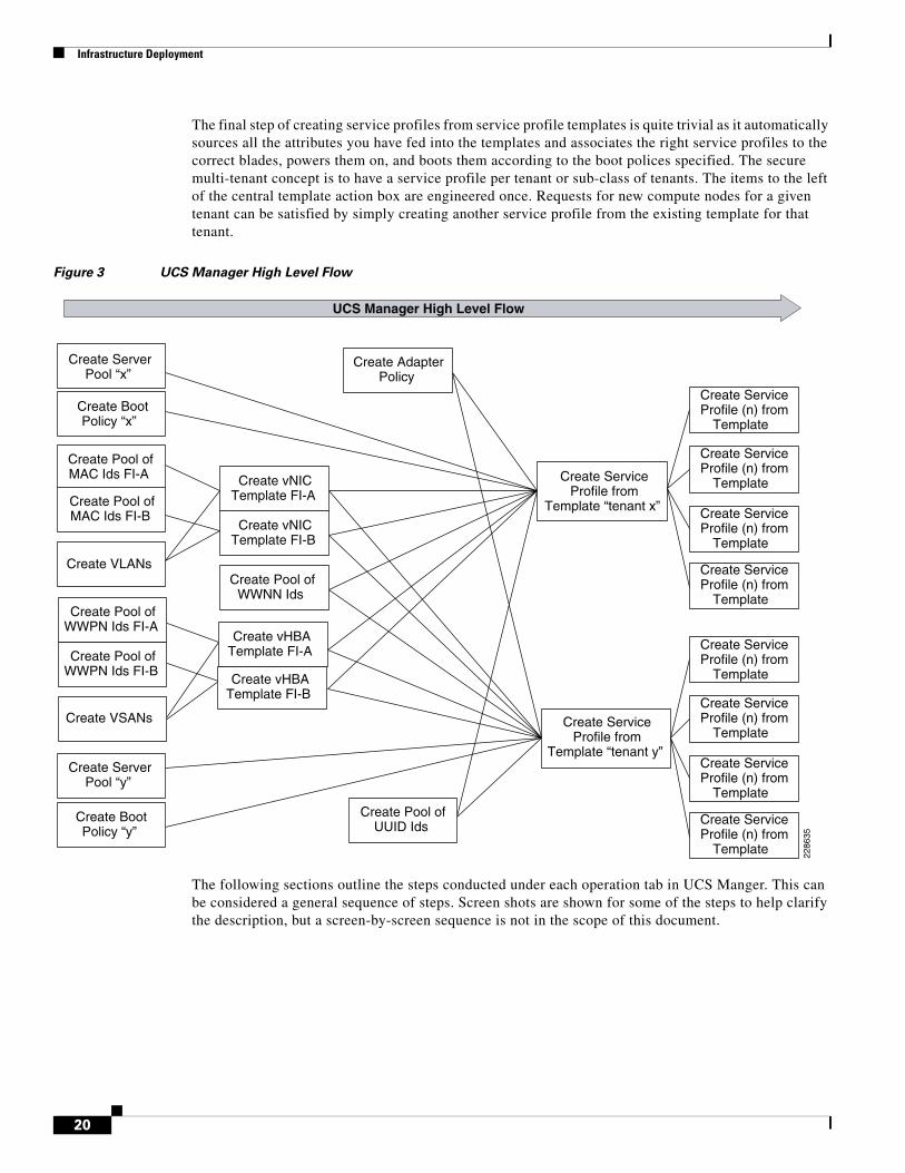
All steps are performed using the UCS Manger Java GUI unless otherwise specified. The best practice for implementing UCS is to first engineer elements such as organizations, resource pools, polices, and templates. This flow is shown graphically in Figure 3. There are two types of service profile templates, updating and initial. Initial templates are generally easier to manage in that changes to the original template do not result in changes to the service profiles created from the template. Updating templates results in the downstream service profiles being immediately updated with any change, which may or may not be desirable depending on the use case and the nature of the change to the template. The SMT design used initial templates.
Figure 3 shows a high-level summary of the overall flow of operations. Each action area is explained in detail throughout this section. The intent of Figure 3 is to show which steps and actions “feed” the subsequent actions, with the flow going from left to right. It can be readily seen that the service profile template is the key construct which, once created, allows rapid creation and provisioning of new service profiles and servers. Not all of the exposed UCS polices and capabilities are shown in Figure 3; it is intended to provide the reader with a guide to the overall flow process.
19
Infrastructure Deployment
The final step of creating service profiles from service profile templates is quite trivial as it automatically sources all the attributes you have fed into the templates and associates the right service profiles to the correct blades, powers them on, and boots them according to the boot polices specified. The secure multi-tenant concept is to have a service profile per tenant or sub-class of tenants. The items to the left of the central template action box are engineered once. Requests for new compute nodes for a given tenant can be satisfied by simply creating another service profile from the existing template for that tenant.
Figure 3 UCS Manager High Level Flow
The following sections outline the steps conducted under each operation tab in UCS Manger. This can be considered a general sequence of steps. Screen shots are shown for some of the steps to help clarify the description, but a screen-by-screen sequence is not in the scope of this document.
Create Pool ofMAC Ids FI-A
Create Pool ofUUID Ids
Create ServerPool “x”
Create vNICTemplate FI-B
Create vNICTemplate FI-A
Create Pool ofWWPN Ids FI-B
Create Pool ofWWPN Ids FI-A
Create Pool ofMAC Ids FI-B
Create vHBATemplate FI-B
Create vHBATemplate FI-A
Create ServiceProfile from
Template “tenant x”
Create AdapterPolicy
Create BootPolicy “x”
Create Pool ofWWNN Ids
Create VLANs
Create VSANs
Create ServiceProfile (n) from
Template
Create ServiceProfile (n) from
Template
Create ServiceProfile (n) from
Template
Create ServiceProfile (n) from
Template
UCS Manager High Level Flow
Create ServiceProfile from
Template “tenant y”
Create BootPolicy “y”
Create ServerPool “y”
Create ServiceProfile (n) from
Template
Create ServiceProfile (n) from
Template
Create ServiceProfile (n) from
Template
Create ServiceProfile (n) from
Template
2286
35
20
Infrastructure Deployment
Initial Infrastructure Setup
UCS Hardware Components Used in the SMT Architecture
A detailed description of all the hardware components is beyond the scope of this document. Detailed documentation for each UCS component can be obtained from: http://www.cisco.com/en/US/docs/unified_computing/ucs/overview/guide/UCS_roadmap.html.
B200 M1 Blade
The half-width blade was used for the SMT design and validation testing. The blade was populated with 48GB of memory and a single I/O mezzanine card. The 2.93 MHz CPU was used. There were eight blades used in the 5108 UCS chassis.
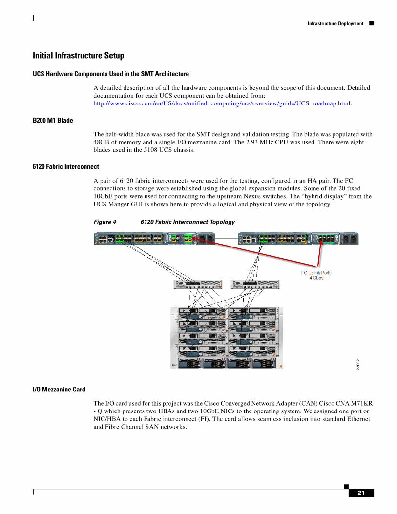
6120 Fabric Interconnect
A pair of 6120 fabric interconnects were used for the testing, configured in an HA pair. The FC connections to storage were established using the global expansion modules. Some of the 20 fixed 10GbE ports were used for connecting to the upstream Nexus switches. The “hybrid display” from the UCS Manger GUI is shown here to provide a logical and physical view of the topology.
Figure 4 6120 Fabric Interconnect Topology
I/O Mezzanine Card
The I/O card used for this project was the Cisco Converged Network Adapter (CAN) Cisco CNA M71KR - Q which presents two HBAs and two 10GbE NICs to the operating system. We assigned one port or NIC/HBA to each Fabric interconnect (FI). The card allows seamless inclusion into standard Ethernet and Fibre Channel SAN networks.
21
Infrastructure Deployment
LAN Configuration (LAN Tab)
Organization Creation
The first step in using UCS in a multi-tenant environment is to leverage the concept of an organization. Once created, all subsequent steps listed below are done “under” the organization that was created versus at the top of the UCS hierarchy (root). This step is not necessary, but it allows very easy separation of resources and policies among different tenants. An organization called “csco_eselab_sc” is created, under which everything else is constructed and then automatically associated.
MAC Pools
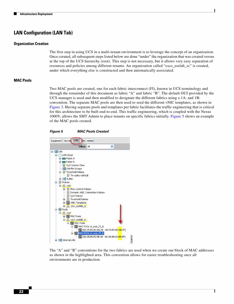
Two MAC pools are created, one for each fabric interconnect (FI), known in UCS terminology and through the remainder of this document as fabric “A” and fabric “B”. The default OUI provided by the UCS manager is used and then modified to designate the different fabrics using a 1A: and 1B: convention. The separate MAC pools are then used to seed the different vNIC templates, as shown in Figure 3. Having separate pools and templates per fabric facilitates the traffic engineering that is critical for this architecture to be built end-to-end. This traffic engineering, which is coupled with the Nexus 1000V, allows the SMT Admin to place tenants on specific fabrics initially. Figure 5 shows an example of the MAC pools created.
Figure 5 MAC Pools Created
The “A” and “B” conventions for the two fabrics are used when we create our block of MAC addresses as shown in the highlighted area. This convention allows for easier troubleshooting once all environments are in production.
22
Infrastructure Deployment
VLANs
Approximately 20 different VLANs are created and used throughout the infrastructure. Creating VLANs is quite trivial and only involves specifying a name and associated ID value. Each VLAN is assigned to each fabric such that upon a failure of either 6120 FI, the partner system is able to serve all the VLAN traffic. The VLANS are assigned to different fabrics during the creation of the vNIC templates. This allows different networks to use independent fabric resources and allows for optimal balancing of load across the entire system. It also provides a mechanism for manual separation of different tenant’s traffic if the goal is to keep them separated on a fabric level. Modifying vLANs is quite trivial (single GUI button) with UCS Manger revisions equal to or later than 1.0(2d). However in the version used in this document (1.0(1e)), modifying existing VLANs is not shown through the GUI, but rather through the CLI, obtained by doing a SSH into the cluster IP address.
The following commands show how to add new VLANs to an existing service profile. This does not require a reboot.
# scope org csco_eselab_sc # scope service-profile sp_netapp11 # scope vnic vNIC1 # create eth-if MKT_Bulk # commit-buffer
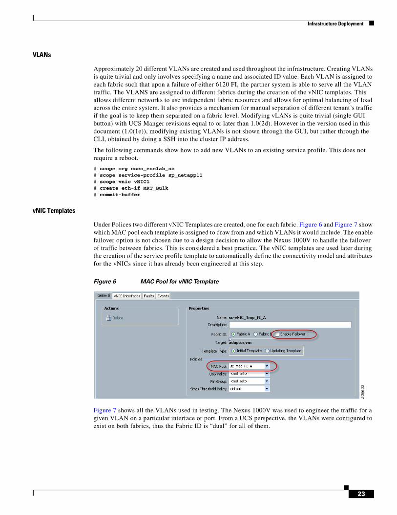
vNIC Templates
Under Polices two different vNIC Templates are created, one for each fabric. Figure 6 and Figure 7 show which MAC pool each template is assigned to draw from and which VLANs it would include. The enable failover option is not chosen due to a design decision to allow the Nexus 1000V to handle the failover of traffic between fabrics. This is considered a best practice. The vNIC templates are used later during the creation of the service profile template to automatically define the connectivity model and attributes for the vNICs since it has already been engineered at this step.
Figure 6 MAC Pool for vNIC Template
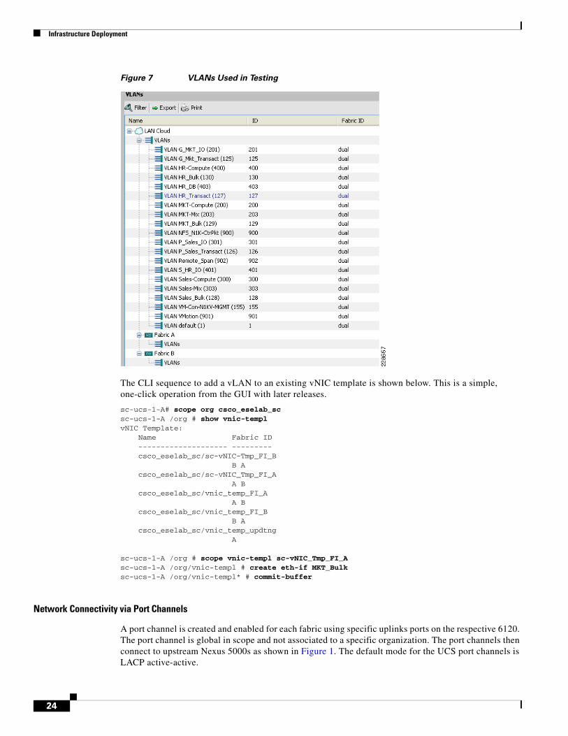
Figure 7 shows all the VLANs used in testing. The Nexus 1000V was used to engineer the traffic for a given VLAN on a particular interface or port. From a UCS perspective, the VLANs were configured to exist on both fabrics, thus the Fabric ID is “dual” for all of them.
23
Infrastructure Deployment
Figure 7 VLANs Used in Testing
The CLI sequence to add a vLAN to an existing vNIC template is shown below. This is a simple, one-click operation from the GUI with later releases.
sc-ucs-1-A# scope org csco_eselab_sc sc-ucs-1-A /org # show vnic-templ vNIC Template: Name Fabric ID -------------------- --------- csco_eselab_sc/sc-vNIC-Tmp_FI_B B A csco_eselab_sc/sc-vNIC_Tmp_FI_A A B csco_eselab_sc/vnic_temp_FI_A A B csco_eselab_sc/vnic_temp_FI_B B A csco_eselab_sc/vnic_temp_updtng A sc-ucs-1-A /org # scope vnic-templ sc-vNIC_Tmp_FI_A sc-ucs-1-A /org/vnic-templ # create eth-if MKT_Bulk sc-ucs-1-A /org/vnic-templ* # commit-buffer
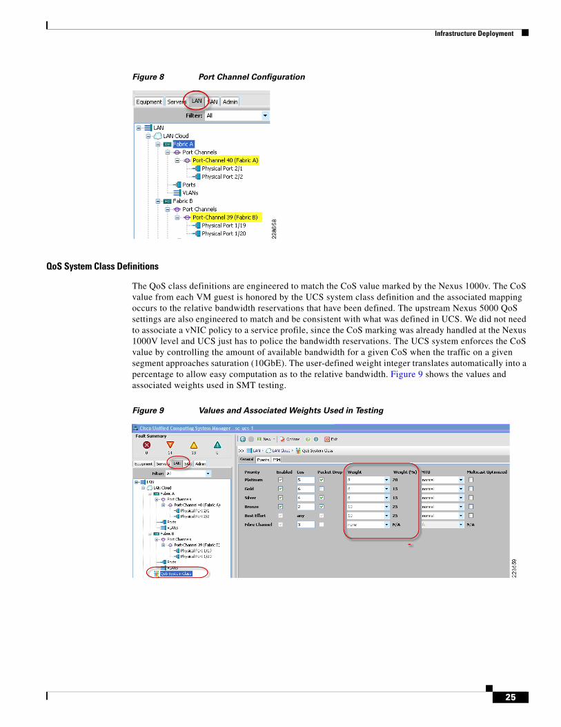
Network Connectivity via Port Channels
A port channel is created and enabled for each fabric using specific uplinks ports on the respective 6120. The port channel is global in scope and not associated to a specific organization. The port channels then connect to upstream Nexus 5000s as shown in Figure 1. The default mode for the UCS port channels is LACP active-active.
24
Infrastructure Deployment
Figure 8 Port Channel Configuration
QoS System Class Definitions
The QoS class definitions are engineered to match the CoS value marked by the Nexus 1000v. The CoS value from each VM guest is honored by the UCS system class definition and the associated mapping occurs to the relative bandwidth reservations that have been defined. The upstream Nexus 5000 QoS settings are also engineered to match and be consistent with what was defined in UCS. We did not need to associate a vNIC policy to a service profile, since the CoS marking was already handled at the Nexus 1000V level and UCS just has to police the bandwidth reservations. The UCS system enforces the CoS value by controlling the amount of available bandwidth for a given CoS when the traffic on a given segment approaches saturation (10GbE). The user-defined weight integer translates automatically into a percentage to allow easy computation as to the relative bandwidth. Figure 9 shows the values and associated weights used in SMT testing.
Figure 9 Values and Associated Weights Used in Testing
25
Infrastructure Deployment
SAN Configuration (SAN Tab)
World Wide Node Name (WWNN) Pool
A single WWNN pool is created for all the blades in the system. As this pool is for the parent FC device node (card itself). it is not necessary to create one for each fabric. This is illustrated in Figure 3.
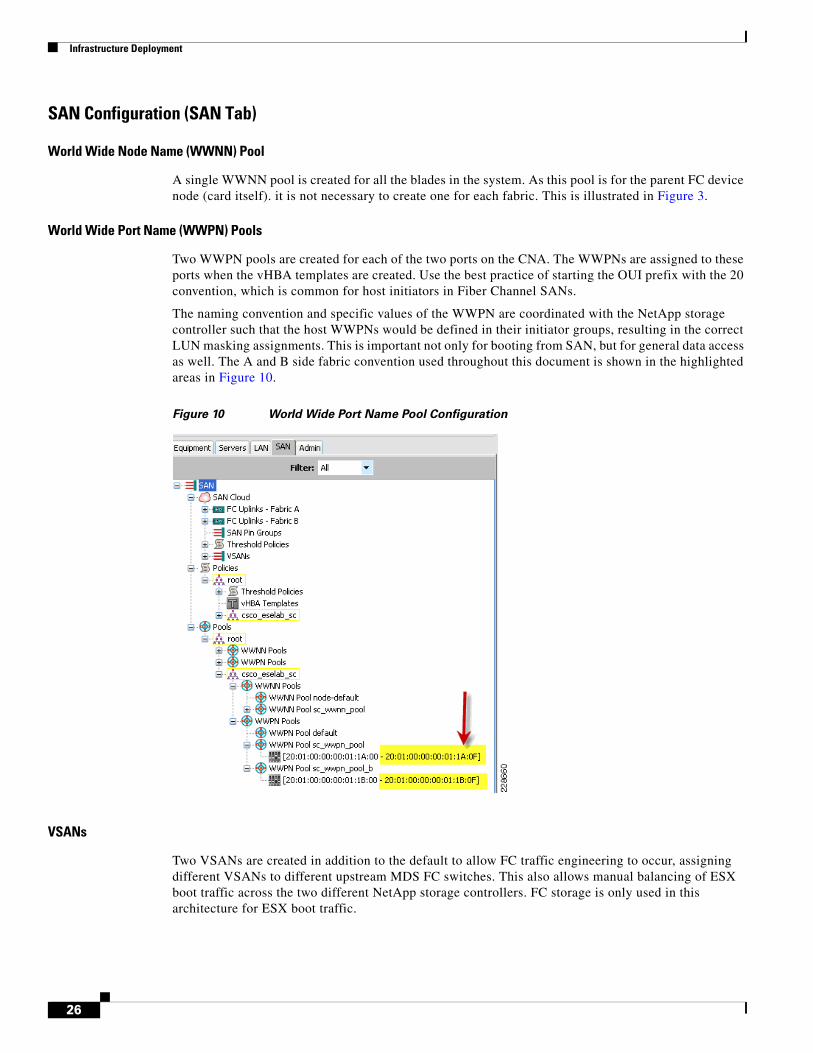
World Wide Port Name (WWPN) Pools
Two WWPN pools are created for each of the two ports on the CNA. The WWPNs are assigned to these ports when the vHBA templates are created. Use the best practice of starting the OUI prefix with the 20 convention, which is common for host initiators in Fiber Channel SANs.
The naming convention and specific values of the WWPN are coordinated with the NetApp storage controller such that the host WWPNs would be defined in their initiator groups, resulting in the correct LUN masking assignments. This is important not only for booting from SAN, but for general data access as well. The A and B side fabric convention used throughout this document is shown in the highlighted areas in Figure 10.
Figure 10 World Wide Port Name Pool Configuration
VSANs
Two VSANs are created in addition to the default to allow FC traffic engineering to occur, assigning different VSANs to different upstream MDS FC switches. This also allows manual balancing of ESX boot traffic across the two different NetApp storage controllers. FC storage is only used in this architecture for ESX boot traffic.
26
Infrastructure Deployment
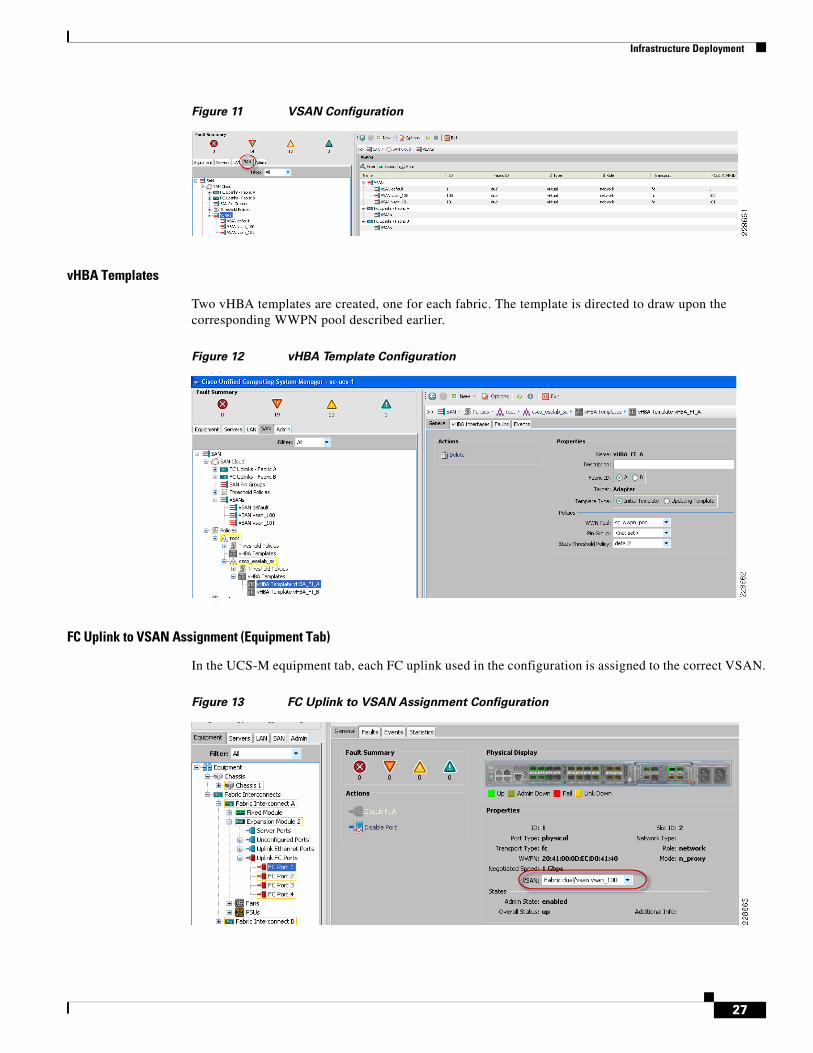
Figure 11 VSAN Configuration
vHBA Templates
Two vHBA templates are created, one for each fabric. The template is directed to draw upon the corresponding WWPN pool described earlier.
Figure 12 vHBA Template Configuration
FC Uplink to VSAN Assignment (Equipment Tab)
In the UCS-M equipment tab, each FC uplink used in the configuration is assigned to the correct VSAN.
Figure 13 FC Uplink to VSAN Assignment Configuration
27
Infrastructure Deployment
Server Configuration (Servers Tab)
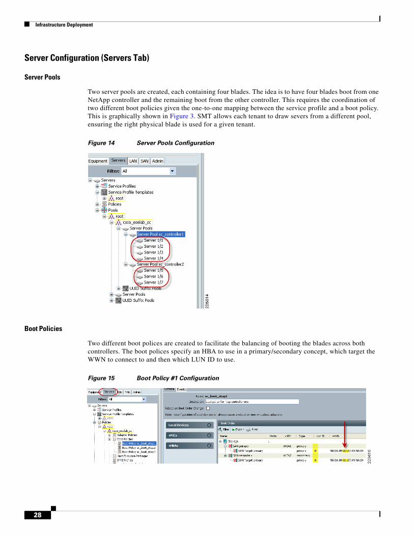
Server Pools
Two server pools are created, each containing four blades. The idea is to have four blades boot from one NetApp controller and the remaining boot from the other controller. This requires the coordination of two different boot policies given the one-to-one mapping between the service profile and a boot policy. This is graphically shown in Figure 3. SMT allows each tenant to draw severs from a different pool, ensuring the right physical blade is used for a given tenant.
Figure 14 Server Pools Configuration
Boot Policies
Two different boot polices are created to facilitate the balancing of booting the blades across both controllers. The boot polices specify an HBA to use in a primary/secondary concept, which target the WWN to connect to and then which LUN ID to use.
Figure 15 Boot Policy #1 Configuration
28
Infrastructure Deployment
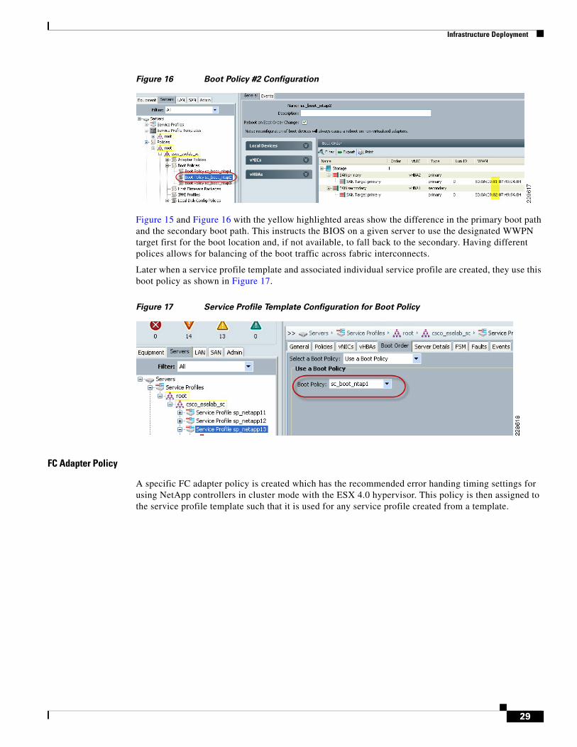
Figure 16 Boot Policy #2 Configuration
Figure 15 and Figure 16 with the yellow highlighted areas show the difference in the primary boot path and the secondary boot path. This instructs the BIOS on a given server to use the designated WWPN target first for the boot location and, if not available, to fall back to the secondary. Having different polices allows for balancing of the boot traffic across fabric interconnects.
Later when a service profile template and associated individual service profile are created, they use this boot policy as shown in Figure 17.
Figure 17 Service Profile Template Configuration for Boot Policy
FC Adapter Policy
A specific FC adapter policy is created which has the recommended error handing timing settings for using NetApp controllers in cluster mode with the ESX 4.0 hypervisor. This policy is then assigned to the service profile template such that it is used for any service profile created from a template.
29
Infrastructure Deployment
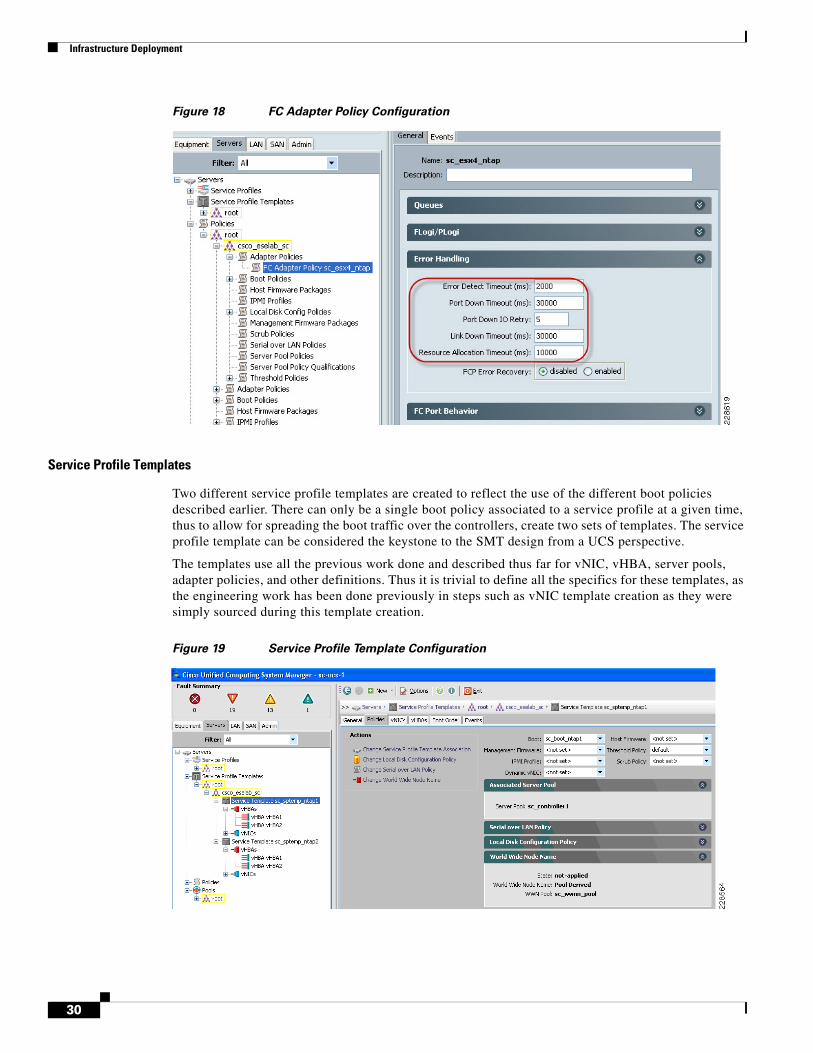
Figure 18 FC Adapter Policy Configuration
Service Profile Templates
Two different service profile templates are created to reflect the use of the different boot policies described earlier. There can only be a single boot policy associated to a service profile at a given time, thus to allow for spreading the boot traffic over the controllers, create two sets of templates. The service profile template can be considered the keystone to the SMT design from a UCS perspective.
The templates use all the previous work done and described thus far for vNIC, vHBA, server pools, adapter policies, and other definitions. Thus it is trivial to define all the specifics for these templates, as the engineering work has been done previously in steps such as vNIC template creation as they were simply sourced during this template creation.
Figure 19 Service Profile Template Configuration
30
Infrastructure Deployment
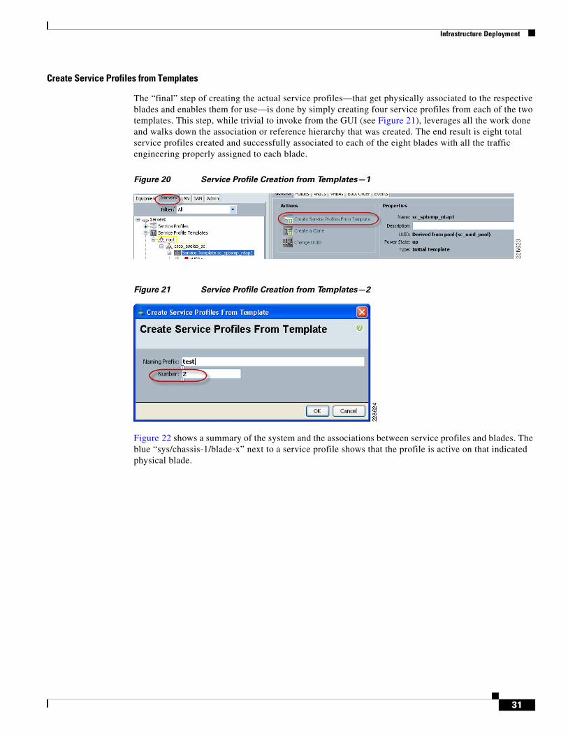
Create Service Profiles from Templates
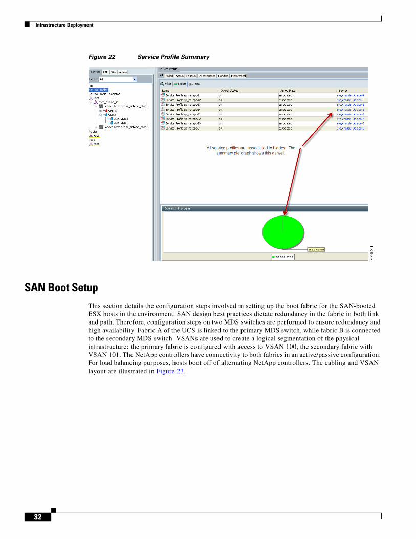
The “final” step of creating the actual service profiles—that get physically associated to the respective blades and enables them for use—is done by simply creating four service profiles from each of the two templates. This step, while trivial to invoke from the GUI (see Figure 21), leverages all the work done and walks down the association or reference hierarchy that was created. The end result is eight total service profiles created and successfully associated to each of the eight blades with all the traffic engineering properly assigned to each blade.
Figure 20 Service Profile Creation from Templates—1
Figure 21 Service Profile Creation from Templates—2
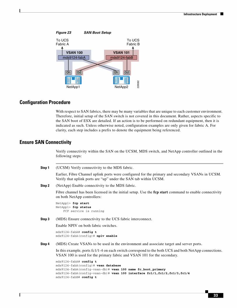
Figure 22 shows a summary of the system and the associations between service profiles and blades. The blue “sys/chassis-1/blade-x” next to a service profile shows that the profile is active on that indicated physical blade.
31
Infrastructure Deployment
Figure 22 Service Profile Summary
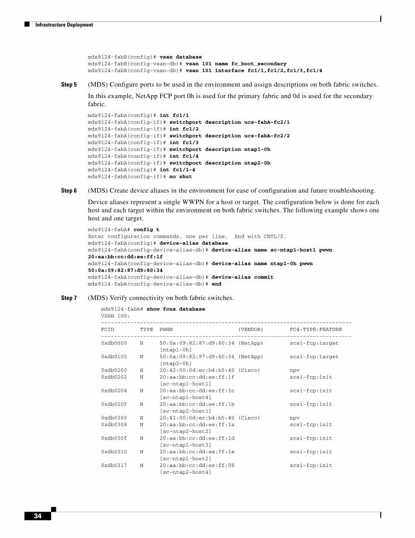
SAN Boot SetupThis section details the configuration steps involved in setting up the boot fabric for the SAN-booted ESX hosts in the environment. SAN design best practices dictate redundancy in the fabric in both link and path. Therefore, configuration steps on two MDS switches are performed to ensure redundancy and high availability. Fabric A of the UCS is linked to the primary MDS switch, while fabric B is connected to the secondary MDS switch. VSANs are used to create a logical segmentation of the physical infrastructure: the primary fabric is configured with access to VSAN 100, the secondary fabric with VSAN 101. The NetApp controllers have connectivity to both fabrics in an active/passive configuration. For load balancing purposes, hosts boot off of alternating NetApp controllers. The cabling and VSAN layout are illustrated in Figure 23.
32
Infrastructure Deployment
Figure 23 SAN Boot Setup
Configuration Procedure
With respect to SAN fabrics, there may be many variables that are unique to each customer environment. Therefore, initial setup of the SAN switch is not covered in this document. Rather, aspects specific to the SAN boot of ESX are detailed. If an action is to be performed on redundant equipment, then it is indicated as such. Unless otherwise noted, configuration examples are only given for fabric A. For clarity, each step includes a prefix to denote the equipment being referenced.
Ensure SAN Connectivity
Verify connectivity within the SAN on the UCSM, MDS switch, and NetApp controller outlined in the following steps:
Step 1 (UCSM) Verify connectivity to the MDS fabric.
Earlier, Fibre Channel uplink ports were configured for the primary and secondary VSANs in UCSM. Verify that uplink ports are “up” under the SAN tab within UCSM.
Step 2 (NetApp) Enable connectivity to the MDS fabric.
Fibre channel has been licensed in the initial setup. Use the fcp start command to enable connectivity on both NetApp controllers:
NetApp1> fcp start NetApp1> fcp status FCP service is running
Step 3 (MDS) Ensure connectivity to the UCS fabric interconnect.
Enable NPIV on both fabric switches.
mds9124-fabA# config t mds9124-fabA(config)# npiv enable
Step 4 (MDS) Create VSANs to be used in the environment and associate target and server ports.
In this example, ports fc1/1-4 on each switch correspond to the both UCS and both NetApp connections. VSAN 100 is used for the primary fabric and VSAN 101 for the secondary.
mds9124-fabA# config t mds9124-fabA(config)# vsan database mds9124-fabA(config-vsan-db)# vsan 100 name fc_boot_primary mds9124-fabA(config-vsan-db)# vsan 100 interface fc1/1,fc1/2,fc1/3,fc1/4 mds9124-fabB# config t
mds9124-fabA
0h 0d0h 0d
VSAN 100 VSAN 101
To UCSFabric A
NetApp1 NetApp2
To UCSFabric B
mds9124-fabB
2285
82
33
Infrastructure Deployment
mds9124-fabB(config)# vsan database mds9124-fabB(config-vsan-db)# vsan 101 name fc_boot_secondary mds9124-fabB(config-vsan-db)# vsan 101 interface fc1/1,fc1/2,fc1/3,fc1/4
Step 5 (MDS) Configure ports to be used in the environment and assign descriptions on both fabric switches.
In this example, NetApp FCP port 0h is used for the primary fabric and 0d is used for the secondary fabric.
mds9124-fabA(config)# int fc1/1 mds9124-fabA(config-if)# switchport description ucs-fabA-fc2/1 mds9124-fabA(config-if)# int fc1/2 mds9124-fabA(config-if)# switchport description ucs-fabA-fc2/2 mds9124-fabA(config-if)# int fc1/3 mds9124-fabA(config-if)# switchport description ntap1-0h mds9124-fabA(config-if)# int fc1/4 mds9124-fabA(config-if)# switchport description ntap2-0h mds9124-fabA(config)# int fc1/1-4 mds9124-fabA(config-if)# no shut
Step 6 (MDS) Create device aliases in the environment for ease of configuration and future troubleshooting.
Device aliases represent a single WWPN for a host or target. The configuration below is done for each host and each target within the environment on both fabric switches. The following example shows one host and one target.
mds9124-fabA# config t Enter configuration commands, one per line. End with CNTL/Z. mds9124-fabA(config)# device-alias database mds9124-fabA(config-device-alias-db)# device-alias name sc-ntap1-host1 pwwn 20:aa:bb:cc:dd:ee:ff:1f mds9124-fabA(config-device-alias-db)# device-alias name ntap1-0h pwwn 50:0a:09:82:87:d9:80:34 mds9124-fabA(config-device-alias-db)# device-alias commit mds9124-fabA(config-device-alias-db)# end
Step 7 (MDS) Verify connectivity on both fabric switches.
mds9124-fabA# show fcns database VSAN 100: ----------------------------------------------------------------------------- FCID TYPE PWWN (VENDOR) FC4-TYPE:FEATURE ----------------------------------------------------------------------------- 0xdb0000 N 50:0a:09:82:87:d9:80:34 (NetApp) scsi-fcp:target [ntap1-0h] 0xdb0100 N 50:0a:09:82:97:d9:80:34 (NetApp) scsi-fcp:target [ntap2-0h] 0xdb0200 N 20:42:00:0d:ec:b4:b5:40 (Cisco) npv 0xdb0202 N 20:aa:bb:cc:dd:ee:ff:1f scsi-fcp:init [sc-ntap1-host1] 0xdb0204 N 20:aa:bb:cc:dd:ee:ff:1c scsi-fcp:init [sc-ntap1-host4] 0xdb020f N 20:aa:bb:cc:dd:ee:ff:1b scsi-fcp:init [sc-ntap2-host1] 0xdb0300 N 20:41:00:0d:ec:b4:b5:40 (Cisco) npv 0xdb0308 N 20:aa:bb:cc:dd:ee:ff:1a scsi-fcp:init [sc-ntap2-host2] 0xdb030f N 20:aa:bb:cc:dd:ee:ff:1d scsi-fcp:init [sc-ntap1-host3] 0xdb0310 N 20:aa:bb:cc:dd:ee:ff:1e scsi-fcp:init [sc-ntap1-host2] 0xdb0317 N 20:aa:bb:cc:dd:ee:ff:08 scsi-fcp:init [sc-ntap2-host4]
34
Infrastructure Deployment
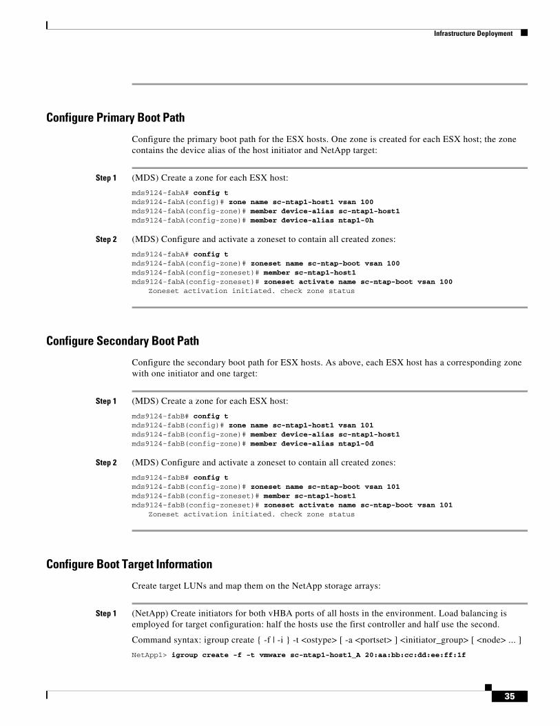
Configure Primary Boot Path
Configure the primary boot path for the ESX hosts. One zone is created for each ESX host; the zone contains the device alias of the host initiator and NetApp target:
Step 1 (MDS) Create a zone for each ESX host:
mds9124-fabA# config t mds9124-fabA(config)# zone name sc-ntap1-host1 vsan 100 mds9124-fabA(config-zone)# member device-alias sc-ntap1-host1 mds9124-fabA(config-zone)# member device-alias ntap1-0h
Step 2 (MDS) Configure and activate a zoneset to contain all created zones:
mds9124-fabA# config t mds9124-fabA(config-zone)# zoneset name sc-ntap-boot vsan 100 mds9124-fabA(config-zoneset)# member sc-ntap1-host1 mds9124-fabA(config-zoneset)# zoneset activate name sc-ntap-boot vsan 100
Zoneset activation initiated. check zone status
Configure Secondary Boot Path
Configure the secondary boot path for ESX hosts. As above, each ESX host has a corresponding zone with one initiator and one target:
Step 1 (MDS) Create a zone for each ESX host:
mds9124-fabB# config t mds9124-fabB(config)# zone name sc-ntap1-host1 vsan 101 mds9124-fabB(config-zone)# member device-alias sc-ntap1-host1 mds9124-fabB(config-zone)# member device-alias ntap1-0d
Step 2 (MDS) Configure and activate a zoneset to contain all created zones:
mds9124-fabB# config t mds9124-fabB(config-zone)# zoneset name sc-ntap-boot vsan 101 mds9124-fabB(config-zoneset)# member sc-ntap1-host1 mds9124-fabB(config-zoneset)# zoneset activate name sc-ntap-boot vsan 101
Zoneset activation initiated. check zone status
Configure Boot Target Information
Create target LUNs and map them on the NetApp storage arrays:
Step 1 (NetApp) Create initiators for both vHBA ports of all hosts in the environment. Load balancing is employed for target configuration: half the hosts use the first controller and half use the second.
Command syntax: igroup create { -f | -i } -t <ostype> [ -a <portset> ] <initiator_group> [ <node> ... ]
NetApp1> igroup create -f -t vmware sc-ntap1-host1_A 20:aa:bb:cc:dd:ee:ff:1f
35
Infrastructure Deployment
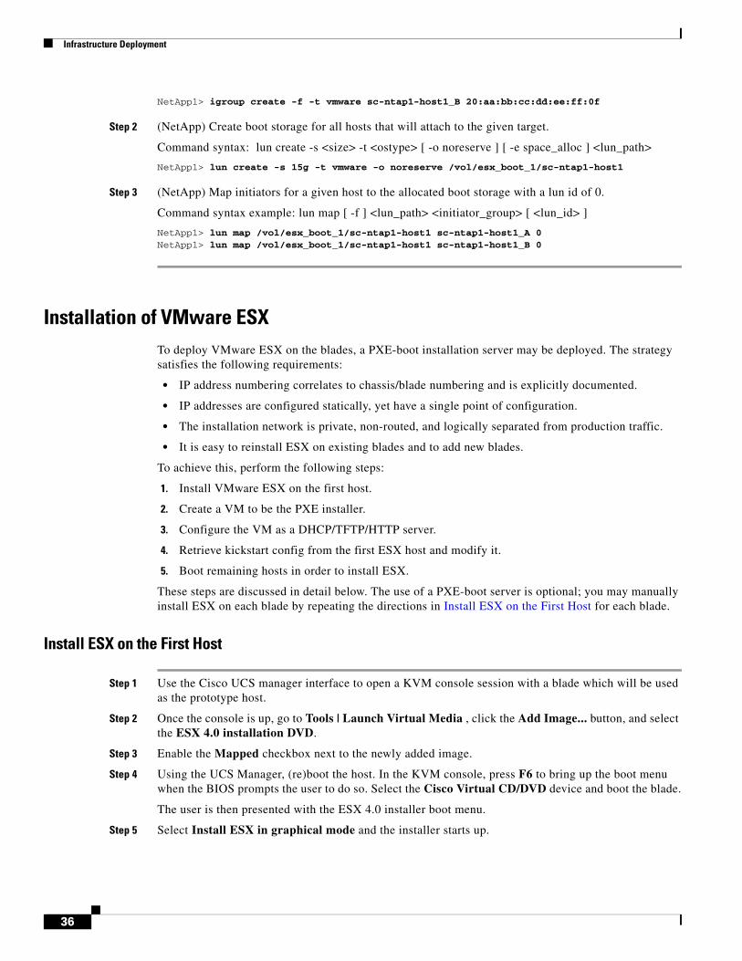
NetApp1> igroup create -f -t vmware sc-ntap1-host1_B 20:aa:bb:cc:dd:ee:ff:0f
Step 2 (NetApp) Create boot storage for all hosts that will attach to the given target.
Command syntax: lun create -s <size> -t <ostype> [ -o noreserve ] [ -e space_alloc ] <lun_path>
NetApp1> lun create -s 15g -t vmware -o noreserve /vol/esx_boot_1/sc-ntap1-host1
Step 3 (NetApp) Map initiators for a given host to the allocated boot storage with a lun id of 0.
Command syntax example: lun map [ -f ] <lun_path> <initiator_group> [ <lun_id> ]
NetApp1> lun map /vol/esx_boot_1/sc-ntap1-host1 sc-ntap1-host1_A 0 NetApp1> lun map /vol/esx_boot_1/sc-ntap1-host1 sc-ntap1-host1_B 0
Installation of VMware ESXTo deploy VMware ESX on the blades, a PXE-boot installation server may be deployed. The strategy satisfies the following requirements:
• IP address numbering correlates to chassis/blade numbering and is explicitly documented.
• IP addresses are configured statically, yet have a single point of configuration.
• The installation network is private, non-routed, and logically separated from production traffic.
• It is easy to reinstall ESX on existing blades and to add new blades.
To achieve this, perform the following steps:
1. Install VMware ESX on the first host.
2. Create a VM to be the PXE installer.
3. Configure the VM as a DHCP/TFTP/HTTP server.
4. Retrieve kickstart config from the first ESX host and modify it.
5. Boot remaining hosts in order to install ESX.
These steps are discussed in detail below. The use of a PXE-boot server is optional; you may manually install ESX on each blade by repeating the directions in Install ESX on the First Host for each blade.
Install ESX on the First Host
Step 1 Use the Cisco UCS manager interface to open a KVM console session with a blade which will be used as the prototype host.
Step 2 Once the console is up, go to Tools | Launch Virtual Media , click the Add Image... button, and select the ESX 4.0 installation DVD.
Step 3 Enable the Mapped checkbox next to the newly added image.
Step 4 Using the UCS Manager, (re)boot the host. In the KVM console, press F6 to bring up the boot menu when the BIOS prompts the user to do so. Select the Cisco Virtual CD/DVD device and boot the blade.
The user is then presented with the ESX 4.0 installer boot menu.
Step 5 Select Install ESX in graphical mode and the installer starts up.
36
Infrastructure Deployment
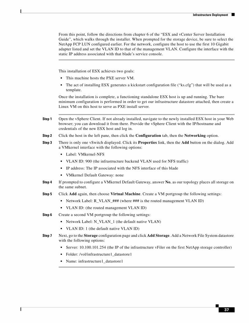
From this point, follow the directions from chapter 6 of the “ESX and vCenter Server Installation Guide”, which walks through the installer. When prompted for the storage device, be sure to select the NetApp FCP LUN configured earlier. For the network, configure the host to use the first 10 Gigabit adapter listed and set the VLAN ID to that of the management VLAN. Configure the interface with the static IP address associated with that blade’s service console.
This installation of ESX achieves two goals:
• This machine hosts the PXE server VM.
• The act of installing ESX generates a kickstart configuration file (“ks.cfg”) that will be used as a template.
Once the installation is complete, a functioning standalone ESX host is up and running. The bare minimum configuration is performed in order to get our infrastructure datastore attached, then create a Linux VM on this host to serve as PXE install server.
Step 1 Open the vSphere Client. If not already installed, navigate to the newly installed ESX host in your Web browser; you can download it from there. Provide the vSphere Client with the IP/hostname and credentials of the new ESX host and log in.
Step 2 Click the host in the left pane, then click the Configuration tab, then the Networking option.
Step 3 There is only one vSwitch displayed. Click its Properties link, then the Add button on the dialog. Add a VMkernel interface with the following options:
• Label: VMkernel-NFS
• VLAN ID: 900 (the infrastructure backend VLAN used for NFS traffic)
• IP address: The IP associated with the NFS interface of this blade
• VMkernel Default Gateway: none
Step 4 If prompted to configure a VMkernel Default Gateway, answer No, as our topology places all storage on the same subnet.
Step 5 Click Add again, then choose Virtual Machine. Create a VM portgroup the following settings:
• Network Label: R_VLAN_### (where ### is the routed management VLAN ID)
• VLAN ID: (the routed management VLAN ID)
Step 6 Create a second VM portgroup the following settings:
• Network Label: N_VLAN_1 (the default native VLAN)
• VLAN ID: 1 (the default native VLAN ID)
Step 7 Next, go to the Storage configuration page and click Add Storage. Add a Network File System datastore with the following options:
• Server: 10.100.101.254 (the IP of the infrastructure vFiler on the first NetApp storage controller)
• Folder: /vol/infrastructure1_datastore1
• Name: infrastructure1_datastore1
37
Infrastructure Deployment
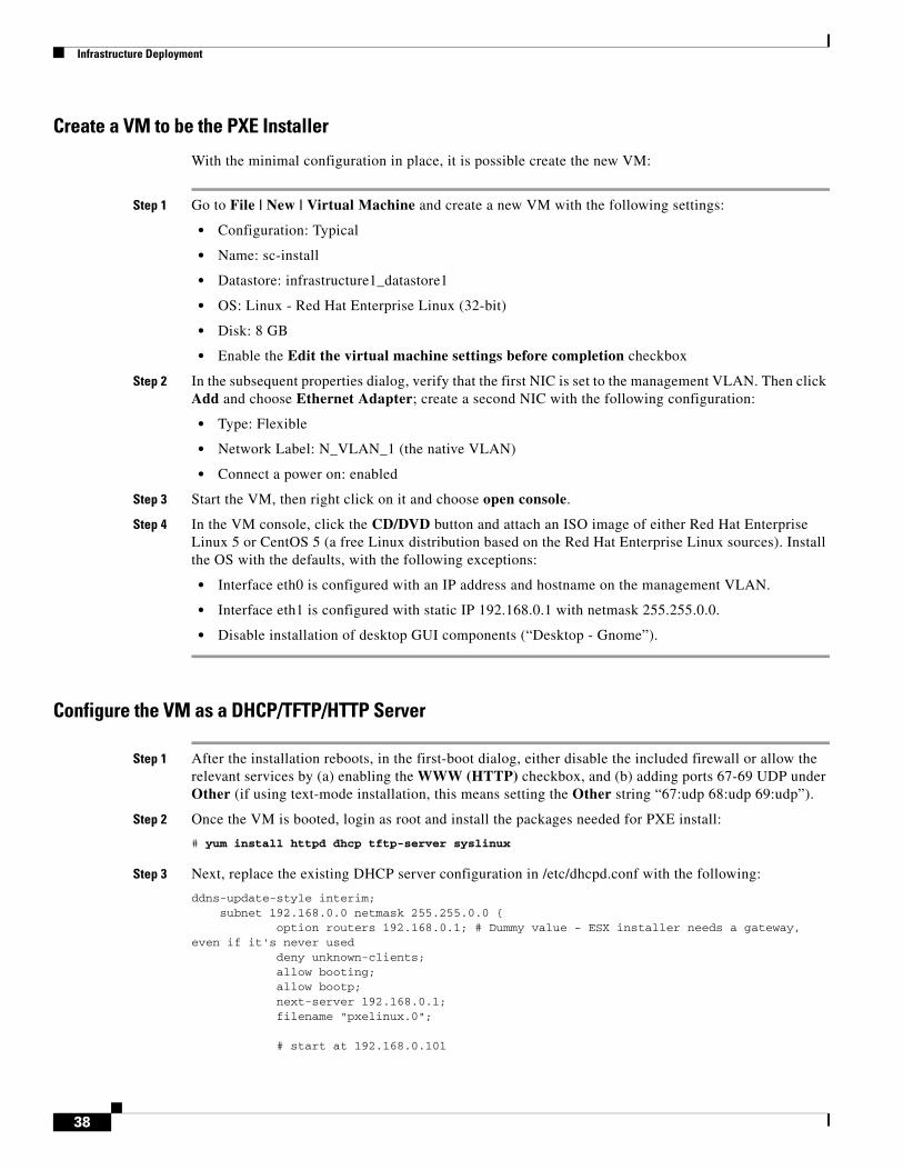
Create a VM to be the PXE Installer
With the minimal configuration in place, it is possible create the new VM:
Step 1 Go to File | New | Virtual Machine and create a new VM with the following settings:
• Configuration: Typical
• Name: sc-install
• Datastore: infrastructure1_datastore1
• OS: Linux - Red Hat Enterprise Linux (32-bit)
• Disk: 8 GB
• Enable the Edit the virtual machine settings before completion checkbox
Step 2 In the subsequent properties dialog, verify that the first NIC is set to the management VLAN. Then click Add and choose Ethernet Adapter; create a second NIC with the following configuration:
• Type: Flexible
• Network Label: N_VLAN_1 (the native VLAN)
• Connect a power on: enabled
Step 3 Start the VM, then right click on it and choose open console.
Step 4 In the VM console, click the CD/DVD button and attach an ISO image of either Red Hat Enterprise Linux 5 or CentOS 5 (a free Linux distribution based on the Red Hat Enterprise Linux sources). Install the OS with the defaults, with the following exceptions:
• Interface eth0 is configured with an IP address and hostname on the management VLAN.
• Interface eth1 is configured with static IP 192.168.0.1 with netmask 255.255.0.0.
• Disable installation of desktop GUI components (“Desktop - Gnome”).
Configure the VM as a DHCP/TFTP/HTTP Server
Step 1 After the installation reboots, in the first-boot dialog, either disable the included firewall or allow the relevant services by (a) enabling the WWW (HTTP) checkbox, and (b) adding ports 67-69 UDP under Other (if using text-mode installation, this means setting the Other string “67:udp 68:udp 69:udp”).
Step 2 Once the VM is booted, login as root and install the packages needed for PXE install:
# yum install httpd dhcp tftp-server syslinux
Step 3 Next, replace the existing DHCP server configuration in /etc/dhcpd.conf with the following:
ddns-update-style interim; subnet 192.168.0.0 netmask 255.255.0.0 { option routers 192.168.0.1; # Dummy value - ESX installer needs a gateway, even if it's never used deny unknown-clients; allow booting; allow bootp; next-server 192.168.0.1; filename "pxelinux.0";
# start at 192.168.0.101
38
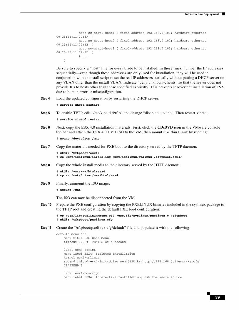
Infrastructure Deployment
host sc-ntap1-host1 { fixed-address 192.168.0.101; hardware ethernet 00:25:B5:11:22:3F; } host sc-ntap1-host2 { fixed-address 192.168.0.102; hardware ethernet 00:25:B5:11:22:3E; } host sc-ntap1-host3 { fixed-address 192.168.0.103; hardware ethernet 00:25:B5:11:22:3D; } # ... }
Be sure to specify a “host” line for every blade to be installed. In those lines, number the IP addresses sequentially—even though these addresses are only used for installation, they will be used in conjunction with an install script to set the real IP addresses statically without putting a DHCP server on any VLAN other than the install VLAN. Indicate “deny unknown-clients” so that the server does not provide IPs to hosts other than those specified explicitly. This prevents inadvertent installation of ESX due to human error or misconfiguration.
Step 4 Load the updated configuration by restarting the DHCP server:
# service dhcpd restart
Step 5 To enable TFTP, edit “/etc/xinetd.d/tftp” and change “disabled” to “no”. Then restart xinetd:
# service xinetd restart
Step 6 Next, copy the ESX 4.0 installation materials. First, click the CD/DVD icon in the VMware console toolbar and attach the ESX 4.0 DVD ISO to the VM, then mount it within Linux by running:
# mount /dev/cdrom /mnt
Step 7 Copy the materials needed for PXE boot to the directory served by the TFTP daemon:
# mkdir /tftpboot/esx4/# cp /mnt/isolinux/initrd.img /mnt/isolinux/vmlinuz /tftpboot/esx4/
Step 8 Copy the whole install media to the directory served by the HTTP daemon:
# mkdir /var/www/html/esx4# cp -r /mnt/* /var/www/html/esx4
Step 9 Finally, unmount the ISO image:
# umount /mnt
The ISO can now be disconnected from the VM.
Step 10 Prepare the PXE configuration by copying the PXELINUX binaries included in the syslinux package to the TFTP root and creating the default PXE boot configuration:
# cp /usr/lib/syslinux/menu.c32 /usr/lib/syslinux/pxelinux.0 /tftpboot# mkdir /tftpboot/pxelinux.cfg
Step 11 Create the “/tftpboot/pxelinux.cfg/default” file and populate it with the following:
default menu.c32 menu title PXE Boot Menu timeout 300 # TENTHS of a second
label esx4-script menu label ESX4: Scripted Installation kernel esx4/vmlinuz append initrd=esx4/initrd.img mem=512M ks=http://192.168.0.1/esx4/ks.cfg IPAPPEND 3
label esx4-noscript menu label ESX4: Interactive Installation, ask for media source
39
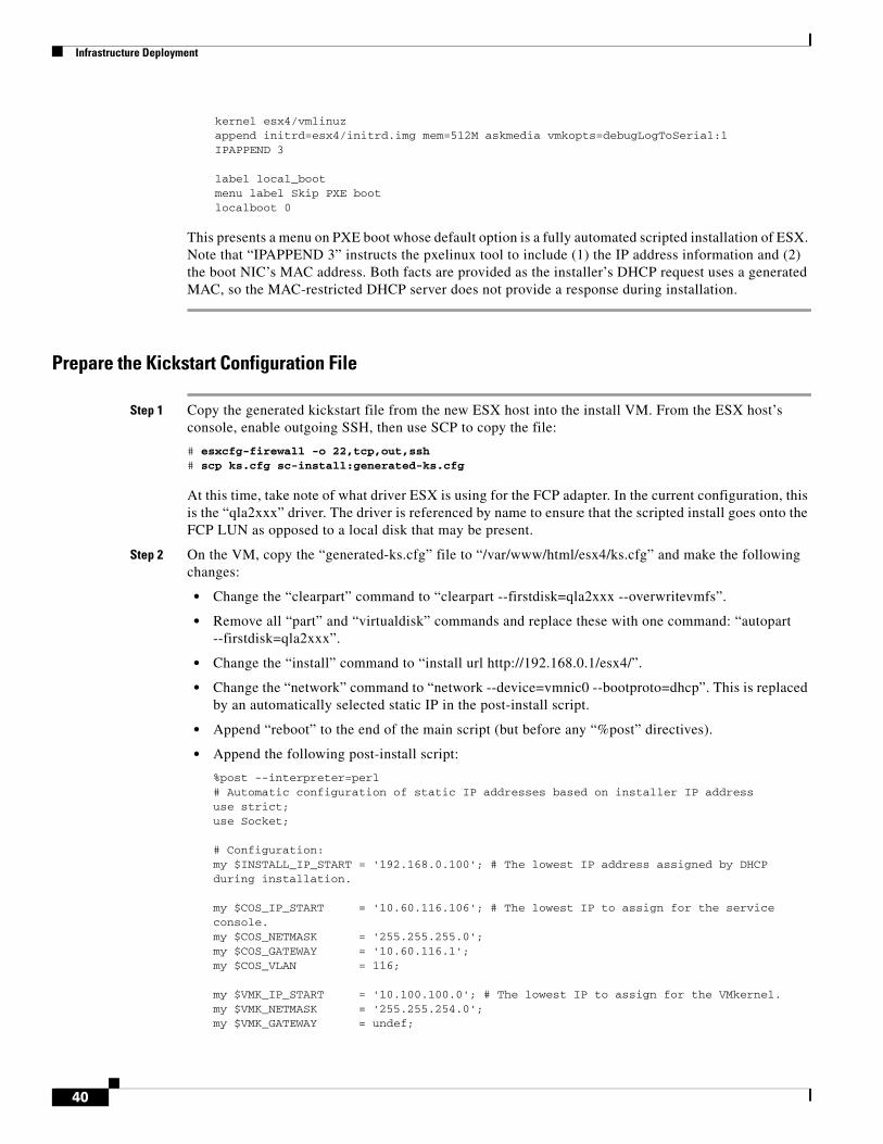
Infrastructure Deployment
kernel esx4/vmlinuz append initrd=esx4/initrd.img mem=512M askmedia vmkopts=debugLogToSerial:1 IPAPPEND 3
label local_boot menu label Skip PXE boot localboot 0
This presents a menu on PXE boot whose default option is a fully automated scripted installation of ESX. Note that “IPAPPEND 3” instructs the pxelinux tool to include (1) the IP address information and (2) the boot NIC’s MAC address. Both facts are provided as the installer’s DHCP request uses a generated MAC, so the MAC-restricted DHCP server does not provide a response during installation.
Prepare the Kickstart Configuration File
Step 1 Copy the generated kickstart file from the new ESX host into the install VM. From the ESX host’s console, enable outgoing SSH, then use SCP to copy the file:
# esxcfg-firewall -o 22,tcp,out,ssh# scp ks.cfg sc-install:generated-ks.cfg
At this time, take note of what driver ESX is using for the FCP adapter. In the current configuration, this is the “qla2xxx” driver. The driver is referenced by name to ensure that the scripted install goes onto the FCP LUN as opposed to a local disk that may be present.
Step 2 On the VM, copy the “generated-ks.cfg” file to “/var/www/html/esx4/ks.cfg” and make the following changes:
• Change the “clearpart” command to “clearpart --firstdisk=qla2xxx --overwritevmfs”.
• Remove all “part” and “virtualdisk” commands and replace these with one command: “autopart --firstdisk=qla2xxx”.
• Change the “install” command to “install url http://192.168.0.1/esx4/”.
• Change the “network” command to “network --device=vmnic0 --bootproto=dhcp”. This is replaced by an automatically selected static IP in the post-install script.
• Append “reboot” to the end of the main script (but before any “%post” directives).
• Append the following post-install script:
%post --interpreter=perl# Automatic configuration of static IP addresses based on installer IP addressuse strict;use Socket;
# Configuration:my $INSTALL_IP_START = '192.168.0.100'; # The lowest IP address assigned by DHCP during installation.
my $COS_IP_START = '10.60.116.106'; # The lowest IP to assign for the service console.my $COS_NETMASK = '255.255.255.0';my $COS_GATEWAY = '10.60.116.1';my $COS_VLAN = 116;
my $VMK_IP_START = '10.100.100.0'; # The lowest IP to assign for the VMkernel.my $VMK_NETMASK = '255.255.254.0';my $VMK_GATEWAY = undef;
40
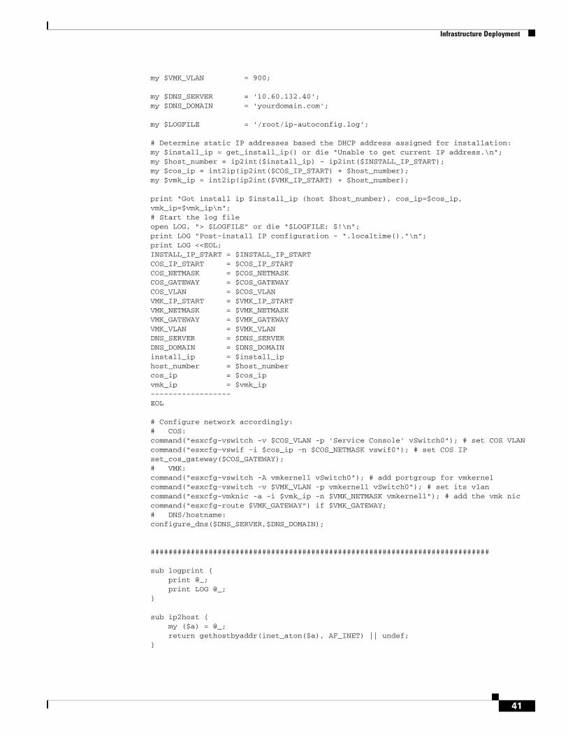
Infrastructure Deployment
my $VMK_VLAN = 900;
my $DNS_SERVER = '10.60.132.40';my $DNS_DOMAIN = 'yourdomain.com';
my $LOGFILE = '/root/ip-autoconfig.log';
# Determine static IP addresses based the DHCP address assigned for installation:my $install_ip = get_install_ip() or die "Unable to get current IP address.\n";my $host_number = ip2int($install_ip) - ip2int($INSTALL_IP_START);my $cos_ip = int2ip(ip2int($COS_IP_START) + $host_number);my $vmk_ip = int2ip(ip2int($VMK_IP_START) + $host_number);
print "Got install ip $install_ip (host $host_number), cos_ip=$cos_ip, vmk_ip=$vmk_ip\n";# Start the log fileopen LOG, "> $LOGFILE" or die "$LOGFILE: $!\n";print LOG "Post-install IP configuration - ".localtime()."\n";print LOG <<EOL;INSTALL_IP_START = $INSTALL_IP_STARTCOS_IP_START = $COS_IP_STARTCOS_NETMASK = $COS_NETMASKCOS_GATEWAY = $COS_GATEWAYCOS_VLAN = $COS_VLANVMK_IP_START = $VMK_IP_STARTVMK_NETMASK = $VMK_NETMASKVMK_GATEWAY = $VMK_GATEWAYVMK_VLAN = $VMK_VLANDNS_SERVER = $DNS_SERVERDNS_DOMAIN = $DNS_DOMAINinstall_ip = $install_iphost_number = $host_numbercos_ip = $cos_ipvmk_ip = $vmk_ip------------------EOL
# Configure network accordingly:# COS:command("esxcfg-vswitch -v $COS_VLAN -p 'Service Console' vSwitch0"); # set COS VLANcommand("esxcfg-vswif -i $cos_ip -n $COS_NETMASK vswif0"); # set COS IPset_cos_gateway($COS_GATEWAY);# VMK:command("esxcfg-vswitch -A vmkernel1 vSwitch0"); # add portgroup for vmkernelcommand("esxcfg-vswitch -v $VMK_VLAN -p vmkernel1 vSwitch0"); # set its vlancommand("esxcfg-vmknic -a -i $vmk_ip -n $VMK_NETMASK vmkernel1"); # add the vmk niccommand("esxcfg-route $VMK_GATEWAY") if $VMK_GATEWAY;# DNS/hostname:configure_dns($DNS_SERVER,$DNS_DOMAIN);
############################################################################
sub logprint { print @_; print LOG @_;}
sub ip2host { my ($a) = @_; return gethostbyaddr(inet_aton($a), AF_INET) || undef;}
41
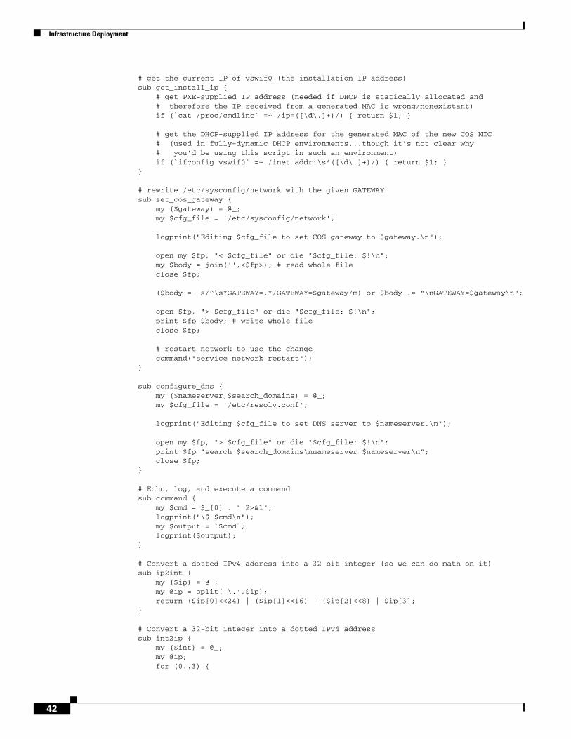
Infrastructure Deployment
# get the current IP of vswif0 (the installation IP address)sub get_install_ip { # get PXE-supplied IP address (needed if DHCP is statically allocated and # therefore the IP received from a generated MAC is wrong/nonexistant) if (`cat /proc/cmdline` =~ /ip=([\d\.]+)/) { return $1; } # get the DHCP-supplied IP address for the generated MAC of the new COS NIC # (used in fully-dynamic DHCP environments...though it's not clear why # you'd be using this script in such an environment) if (`ifconfig vswif0` =~ /inet addr:\s*([\d\.]+)/) { return $1; }}
# rewrite /etc/sysconfig/network with the given GATEWAYsub set_cos_gateway { my ($gateway) = @_; my $cfg_file = '/etc/sysconfig/network'; logprint("Editing $cfg_file to set COS gateway to $gateway.\n"); open my $fp, "< $cfg_file" or die "$cfg_file: $!\n"; my $body = join('',<$fp>); # read whole file close $fp; ($body =~ s/^\s*GATEWAY=.*/GATEWAY=$gateway/m) or $body .= "\nGATEWAY=$gateway\n"; open $fp, "> $cfg_file" or die "$cfg_file: $!\n"; print $fp $body; # write whole file close $fp; # restart network to use the change command("service network restart");}
sub configure_dns { my ($nameserver,$search_domains) = @_; my $cfg_file = '/etc/resolv.conf'; logprint("Editing $cfg_file to set DNS server to $nameserver.\n"); open my $fp, "> $cfg_file" or die "$cfg_file: $!\n"; print $fp "search $search_domains\nnameserver $nameserver\n"; close $fp;}
# Echo, log, and execute a commandsub command { my $cmd = $_[0] . " 2>&1"; logprint("\$ $cmd\n"); my $output = `$cmd`; logprint($output);}
# Convert a dotted IPv4 address into a 32-bit integer (so we can do math on it)sub ip2int { my ($ip) = @_; my @ip = split('\.',$ip); return ($ip[0]<<24) | ($ip[1]<<16) | ($ip[2]<<8) | $ip[3];}
# Convert a 32-bit integer into a dotted IPv4 addresssub int2ip { my ($int) = @_; my @ip; for (0..3) {
42
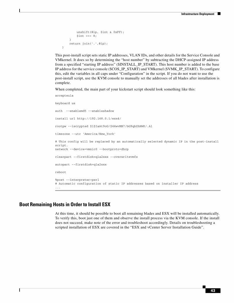
Infrastructure Deployment
unshift(@ip, $int & 0xFF); $int >>= 8; } return join('.',@ip);}
This post-install script sets static IP addresses, VLAN IDs, and other details for the Service Console and VMkernel. It does so by determining the “host number” by subtracting the DHCP-assigned IP address from a specified “starting IP address” ($INSTALL_IP_START). This host number is added to the base IP address for the service console ($COS_IP_START) and VMkernel ($VMK_IP_START). To configure this, edit the variables in all caps under “Configuration” in the script. If you do not want to use the post-install script, use the KVM console to manually set the addresses of all blades after installation is complete.
When completed, the main part of your kickstart script should look something like this:
accepteula
keyboard us
auth --enablemd5 --enableshadow
install url http://192.168.0.1/esx4/
rootpw --iscrypted $1$IaAt9oG/$44wvMB7/bG9qbZhHWK/.A1
timezone --utc 'America/New_York'
# This config will be replaced by an automatically selected dynamic IP in the post-install script.network --device=vmnic0 --bootproto=dhcp
clearpart --firstdisk=qla2xxx --overwritevmfs
autopart --firstdisk=qla2xxx
reboot
%post --interpreter=perl# Automatic configuration of static IP addresses based on installer IP address...
Boot Remaining Hosts in Order to Install ESX
At this time, it should be possible to boot all remaining blades and ESX will be installed automatically. To verify this, boot just one of them and observe the install process via the KVM console. If the install does not succeed, make note of the error and troubleshoot accordingly. Details on troubleshooting a scripted installation of ESX are covered in the “ESX and vCenter Server Installation Guide”.
43
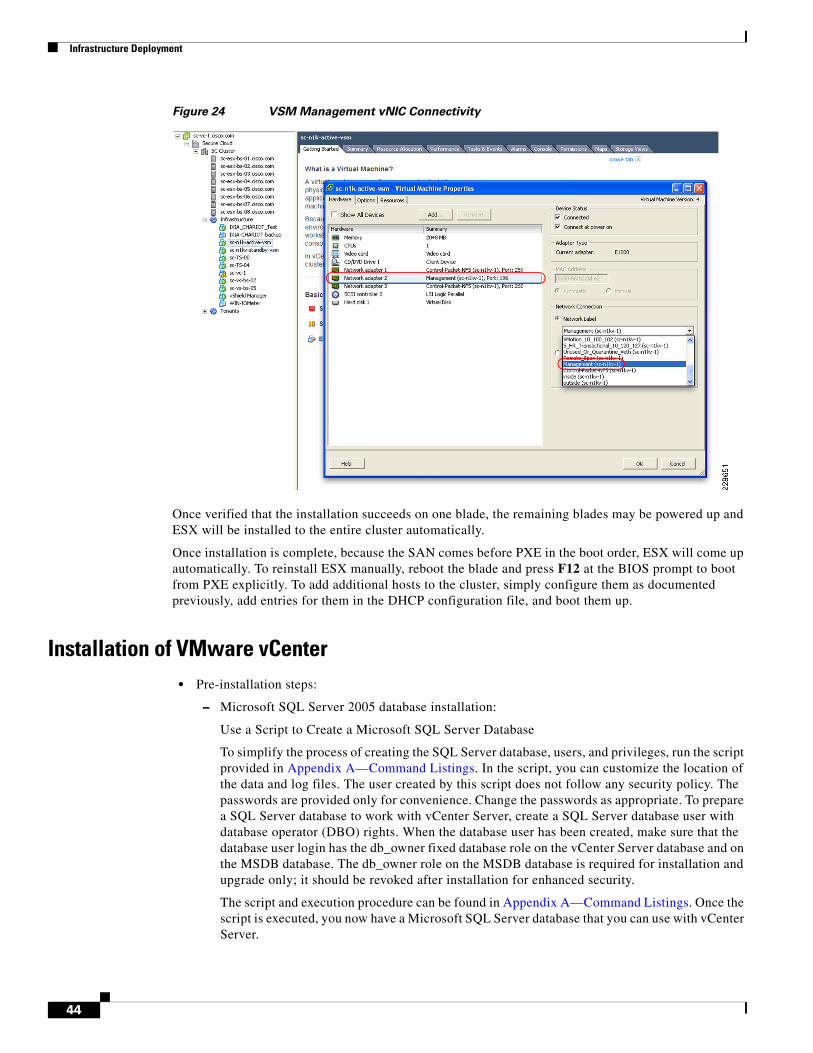
Infrastructure Deployment
Figure 24 VSM Management vNIC Connectivity
Once verified that the installation succeeds on one blade, the remaining blades may be powered up and ESX will be installed to the entire cluster automatically.
Once installation is complete, because the SAN comes before PXE in the boot order, ESX will come up automatically. To reinstall ESX manually, reboot the blade and press F12 at the BIOS prompt to boot from PXE explicitly. To add additional hosts to the cluster, simply configure them as documented previously, add entries for them in the DHCP configuration file, and boot them up.
Installation of VMware vCenter• Pre-installation steps:
– Microsoft SQL Server 2005 database installation:
Use a Script to Create a Microsoft SQL Server Database
To simplify the process of creating the SQL Server database, users, and privileges, run the script provided in Appendix A—Command Listings. In the script, you can customize the location of the data and log files. The user created by this script does not follow any security policy. The passwords are provided only for convenience. Change the passwords as appropriate. To prepare a SQL Server database to work with vCenter Server, create a SQL Server database user with database operator (DBO) rights. When the database user has been created, make sure that the database user login has the db_owner fixed database role on the vCenter Server database and on the MSDB database. The db_owner role on the MSDB database is required for installation and upgrade only; it should be revoked after installation for enhanced security.
The script and execution procedure can be found in Appendix A—Command Listings. Once the script is executed, you now have a Microsoft SQL Server database that you can use with vCenter Server.
44
Infrastructure Deployment
• Create the primary vCenter VM with the follow hardware and resource settings:
– CPU allocation and reservation should be set to 4 GHZ.
– Memory allocation and reservation should be set to 4GB.
– First network adapter needs to be connected to the routable management VLAN port group.
– Add a second network adapter to use as the Channel Interface for vCenter heartbeat; connect the network adapter to the non-routable VLAN port group.
– Follow the procedure on page 86 of ESX and vCenter Installation Guide to set up the ODBC DSN for the vCenter database created in the pre-installation step (http://www.vmware.com/pdf/vsphere4/r40_u1/vsp_40_u1_esx_vc_installation_guide.pdf).
– Install vCenter Server by following the steps on page 100 of ESX and vCenter Installation Guide.
• With vCenter up and running, login via Virtual Infrastructure Client:
– Add a new data center.
– Add all of the Cisco UCS blade servers installed with ESX 4.0 into the new data center.
Installation of vCenter Heartbeat
• Server Architecture Option:
In this design validation, the “V2V” architecture option is chosen for simplicity. Both primary and secondary vCenter Server and Microsoft SQL Server are virtual machines.
• Cloning Technology Option:
– Built-in vCenter virtual machine cloning technology is used.
– Right click on vCenter Server virtual machine and select Clone.
– Ensure the Infrastructure resource pool is selected as the destination for the clone. Right click on Microsoft SQL Server virtual machine and select Clone.
– Ensure the Infrastructure resource pool is selected as the destination for the clone.
• Application Component Option:
Given the Microsoft SQL Server used for vCenter Server is running as a separate virtual machine, vCenter Heartbeat needs to be installed on both primary and secondary SQL Server virtual machine for protection of database.
Preparing the secondary vCenter Server after cloning:
Step 1 Select the Public virtual network adapter and clear the Connected and Connect at power on check boxes.
45
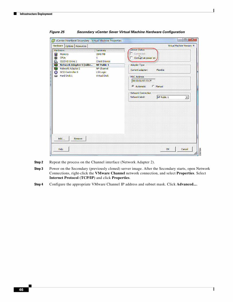
Infrastructure Deployment
Figure 25 Secondary vCenter Sever Virtual Machine Hardware Configuration
Step 2 Repeat the process on the Channel interface (Network Adapter 2).
Step 3 Power on the Secondary (previously cloned) server image. After the Secondary starts, open Network Connections, right-click the VMware Channel network connection, and select Properties. Select Internet Protocol (TCP/IP) and click Properties.
Step 4 Configure the appropriate VMware Channel IP address and subnet mask. Click Advanced....
46
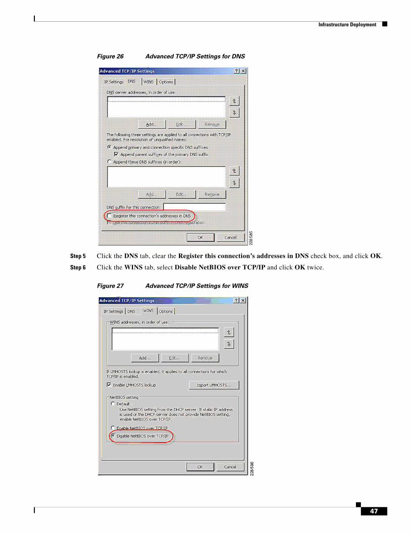
Infrastructure Deployment
Figure 26 Advanced TCP/IP Settings for DNS
Step 5 Click the DNS tab, clear the Register this connection’s addresses in DNS check box, and click OK.
Step 6 Click the WINS tab, select Disable NetBIOS over TCP/IP and click OK twice.
Figure 27 Advanced TCP/IP Settings for WINS
47
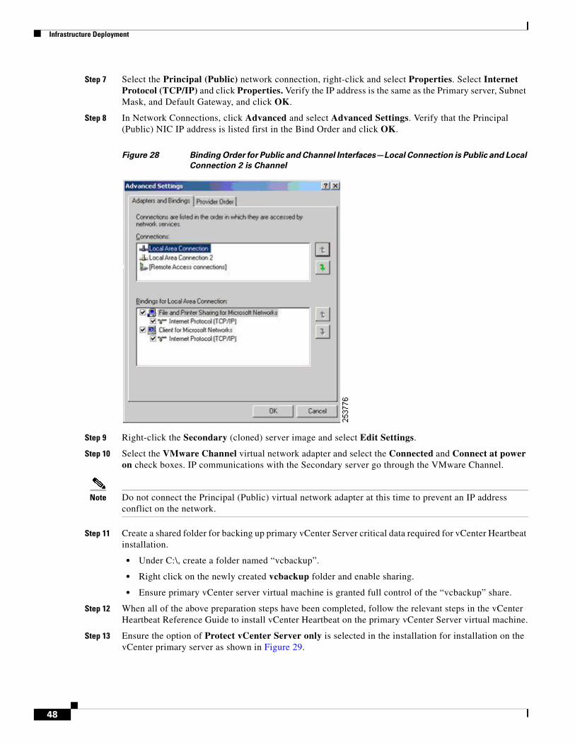
Infrastructure Deployment
Step 7 Select the Principal (Public) network connection, right-click and select Properties. Select Internet Protocol (TCP/IP) and click Properties. Verify the IP address is the same as the Primary server, Subnet Mask, and Default Gateway, and click OK.
Step 8 In Network Connections, click Advanced and select Advanced Settings. Verify that the Principal (Public) NIC IP address is listed first in the Bind Order and click OK.
Figure 28 Binding Order for Public and Channel Interfaces—Local Connection is Public and Local
Connection 2 is Channel
Step 9 Right-click the Secondary (cloned) server image and select Edit Settings.
Step 10 Select the VMware Channel virtual network adapter and select the Connected and Connect at power on check boxes. IP communications with the Secondary server go through the VMware Channel.
Note Do not connect the Principal (Public) virtual network adapter at this time to prevent an IP address conflict on the network.
Step 11 Create a shared folder for backing up primary vCenter Server critical data required for vCenter Heartbeat installation.
• Under C:\, create a folder named “vcbackup”.
• Right click on the newly created vcbackup folder and enable sharing.
• Ensure primary vCenter server virtual machine is granted full control of the “vcbackup” share.
Step 12 When all of the above preparation steps have been completed, follow the relevant steps in the vCenter Heartbeat Reference Guide to install vCenter Heartbeat on the primary vCenter Server virtual machine.
Step 13 Ensure the option of Protect vCenter Server only is selected in the installation for installation on the vCenter primary server as shown in Figure 29.
48
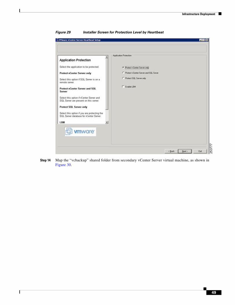
Infrastructure Deployment
Figure 29 Installer Screen for Protection Level by Heartbeat
Step 14 Map the “vcbackup” shared folder from secondary vCenter Server virtual machine, as shown in Figure 30.
49
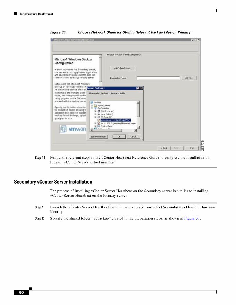
Infrastructure Deployment
Figure 30 Choose Network Share for Storing Relevant Backup Files on Primary
Step 15 Follow the relevant steps in the vCenter Heartbeat Reference Guide to complete the installation on Primary vCenter Server virtual machine.
Secondary vCenter Server Installation
The process of installing vCenter Server Heartbeat on the Secondary server is similar to installing vCenter Server Heartbeat on the Primary server.
Step 1 Launch the vCenter Server Heartbeat installation executable and select Secondary as Physical Hardware Identity.
Step 2 Specify the shared folder “vcbackup” created in the preparation steps, as shown in Figure 31.
50
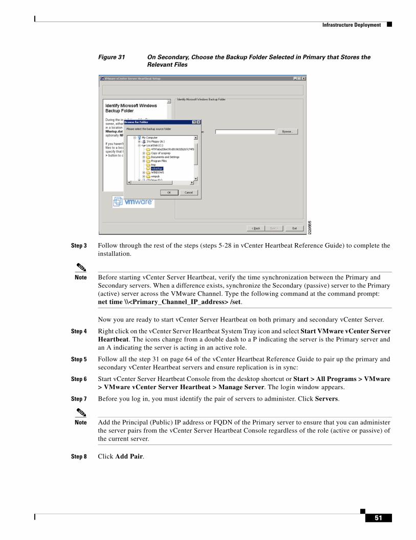
Infrastructure Deployment
Figure 31 On Secondary, Choose the Backup Folder Selected in Primary that Stores the
Relevant Files
Step 3 Follow through the rest of the steps (steps 5-28 in vCenter Heartbeat Reference Guide) to complete the installation.
Note Before starting vCenter Server Heartbeat, verify the time synchronization between the Primary and Secondary servers. When a difference exists, synchronize the Secondary (passive) server to the Primary (active) server across the VMware Channel. Type the following command at the command prompt:net time \\<Primary_Channel_IP_address> /set.
Now you are ready to start vCenter Server Heartbeat on both primary and secondary vCenter Server.
Step 4 Right click on the vCenter Server Heartbeat System Tray icon and select Start VMware vCenter Server Heartbeat. The icons change from a double dash to a P indicating the server is the Primary server and an A indicating the server is acting in an active role.
Step 5 Follow all the step 31 on page 64 of the vCenter Heartbeat Reference Guide to pair up the primary and secondary vCenter Heartbeat servers and ensure replication is in sync:
Step 6 Start vCenter Server Heartbeat Console from the desktop shortcut or Start > All Programs > VMware > VMware vCenter Server Heartbeat > Manage Server. The login window appears.
Step 7 Before you log in, you must identify the pair of servers to administer. Click Servers.
Note Add the Principal (Public) IP address or FQDN of the Primary server to ensure that you can administer the server pairs from the vCenter Server Heartbeat Console regardless of the role (active or passive) of the current server.
Step 8 Click Add Pair.
51
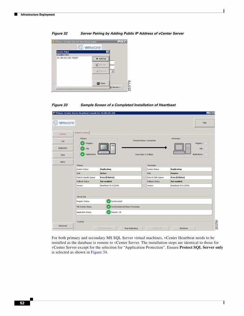
Infrastructure Deployment
Figure 32 Server Pairing by Adding Public IP Address of vCenter Server
Figure 33 Sample Screen of a Completed Installation of Heartbeat
For both primary and secondary MS SQL Server virtual machines, vCenter Heartbeat needs to be installed as the database is remote to vCenter Server. The installation steps are identical to those for vCenter Server except for the selection for “Application Protection”. Ensure Protect SQL Server only is selected as shown in Figure 34.
52
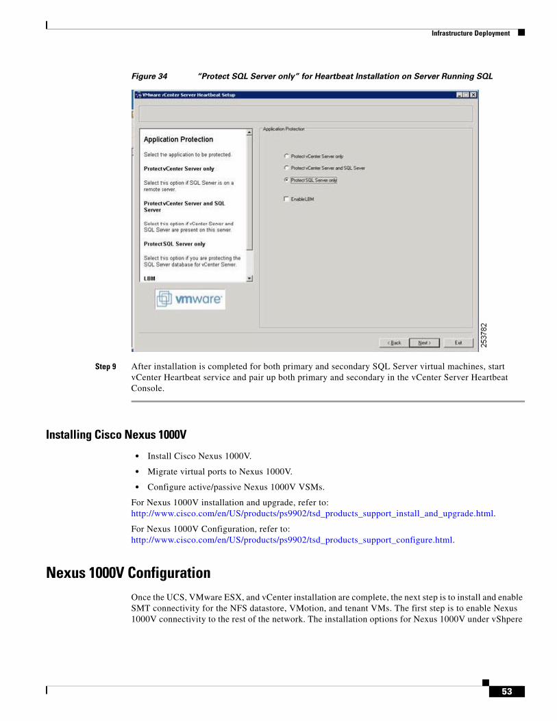
Infrastructure Deployment
Figure 34 “Protect SQL Server only” for Heartbeat Installation on Server Running SQL
Step 9 After installation is completed for both primary and secondary SQL Server virtual machines, start vCenter Heartbeat service and pair up both primary and secondary in the vCenter Server Heartbeat Console.
Installing Cisco Nexus 1000V
• Install Cisco Nexus 1000V.
• Migrate virtual ports to Nexus 1000V.
• Configure active/passive Nexus 1000V VSMs.
For Nexus 1000V installation and upgrade, refer to: http://www.cisco.com/en/US/products/ps9902/tsd_products_support_install_and_upgrade.html.
For Nexus 1000V Configuration, refer to: http://www.cisco.com/en/US/products/ps9902/tsd_products_support_configure.html.
Nexus 1000V ConfigurationOnce the UCS, VMware ESX, and vCenter installation are complete, the next step is to install and enable SMT connectivity for the NFS datastore, VMotion, and tenant VMs. The first step is to enable Nexus 1000V connectivity to the rest of the network. The installation options for Nexus 1000V under vShpere
53
Infrastructure Deployment
are beyond the scope of this document. However, refer to following white paper on generic deployment option: Nexus 1000V Deployment Guide (http://www.cisco.com/en/US/prod/collateral/switches/ps9441/ps9902/guide_c07-556626.html).
Note The Nexus 1000V Deployment Guide does not cover newer options available for connecting uplink (MAC pining) that are used in this deployment guide. The differences in the options used are explained below in the deployment steps.
Note The deployment procedure for installing Nexus 4.0(4)SV1(2) release may requires additional steps. Refer to http://www.cisco.com/ for installation and migration procedures for NxOS 4.0(4)SV1(2) release for Nexus 1000V.
Under UCS systems, multiple network adapter hardware options are available for deployment. This deployment uses the M71KR-Q or M71KR-E series of converged network (CNA) adaptors. The following white paper explains other options: Nexus 1000V Deployment Option with UCS System (http://www.cisco.com/en/US/prod/collateral/switches/ps9441/ps9902/white_paper_c11-558242.html).
At the end of the above design white paper, multiple options are described for the deployment of VSM within UCS systems. This deployment guide uses VSM inside the Cisco UCS as a virtual machine behind VEM. The following steps cover the infrastructure network connectivity requirement for SMT covering Nexus 1000V management, control, and packet VLANs, as well as VMotion and NFS datastore VLANs.
Configuring management, control, and packet VLANs in Nexus 1000V:
Step 1 As per SMT design guide, the management of Nexus 1000V is classified in infrastructure management VLAN:
vlan 155 name VM_Con-N1kV-Mgmt_172_26_155 interface mgmt0 ip address 172.26.155.22/25
Step 2 VMWare vSphere management and the Nexus 1000V connection to vSphere are also defined under infrastructure management:
svs connection VC protocol vmware-vim remote ip address 172.26.155.100 port 80 vmware dvs uuid "e8 7f 30 50 a8 5c ff e4-7b e1 bd 39 d6 8e 52 4a" datacenter-name Secure Cloud connect
Step 3 The control and packet VLANs are consolidated within the NFS datastore VLAN:
vlan 900 name NFS_DataStore-N1K-CtrPkt_100_100'
The control plane, packet, and NFS datastore VLAN are also treated as a “system VLAN”. The system VLAN is a VLAN on a port that needs to be brought up before the VEM contacts the VSM. The system VLAN is configured as part of port-profile which attaches ESX server connectivity to the rest of the network. This design uses port-profile per VLAN.
Step 4 Three port-profiles are required for Nexus 1000V infrastructure connectivity:
54
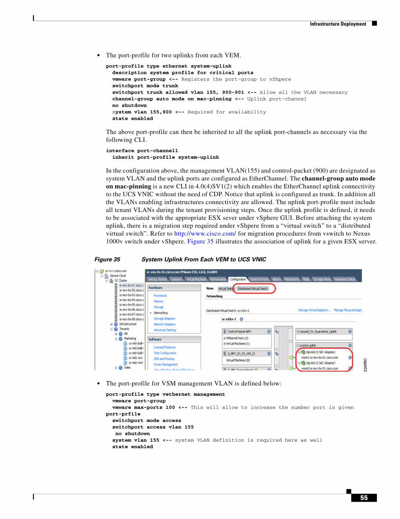
Infrastructure Deployment
• The port-profile for two uplinks from each VEM.
port-profile type ethernet system-uplink description system profile for critical ports vmware port-group <-- Registers the port-group to vShpere switchport mode trunk switchport trunk allowed vlan 155, 900-901 <-- Allow all the VLAN necessary channel-group auto mode on mac-pinning <-- Uplink port-channel no shutdown system vlan 155,900 <-- Required for availability state enabled
The above port-profile can then be inherited to all the uplink port-channels as necessary via the following CLI.
interface port-channel1 inherit port-profile system-uplink
In the configuration above, the management VLAN(155) and control-packet (900) are designated as system VLAN and the uplink ports are configured as EtherChannel. The channel-group auto mode on mac-pinning is a new CLI in 4.0(4)SV1(2) which enables the EtherChannel uplink connectivity to the UCS VNIC without the need of CDP. Notice that uplink is configured as trunk. In addition all the VLANs enabling infrastructures connectivity are allowed. The uplink port-profile must include all tenant VLANs during the tenant provisioning steps. Once the uplink profile is defined, it needs to be associated with the appropriate ESX sever under vSphere GUI. Before attaching the system uplink, there is a migration step required under vShpere from a “virtual switch” to a “distributed virtual switch”. Refer to http://www.cisco.com/ for migration procedures from vswitch to Nexus 1000v switch under vShpere. Figure 35 illustrates the association of uplink for a given ESX server.
Figure 35 System Uplink From Each VEM to UCS VNIC
• The port-profile for VSM management VLAN is defined below:
port-profile type vethernet management vmware port-group vmware max-ports 100 <-- This will allow to increase the number port in given port-prfile switchport mode access switchport access vlan 155 no shutdown system vlan 155 <-- system VLAN definition is required here as well state enabled
55
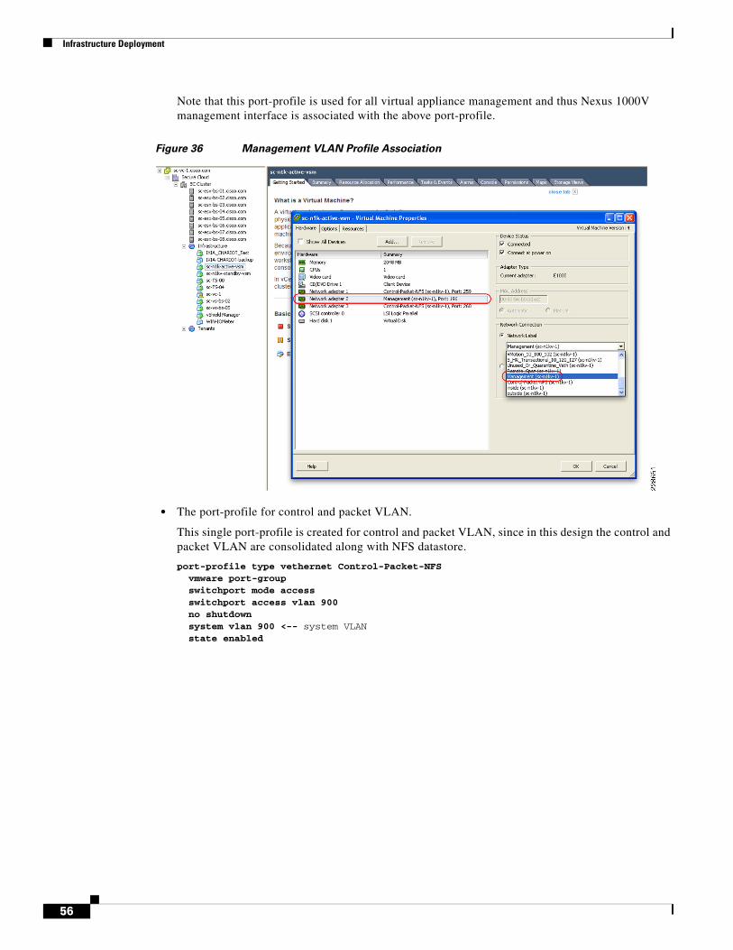
Infrastructure Deployment
Note that this port-profile is used for all virtual appliance management and thus Nexus 1000V management interface is associated with the above port-profile.
Figure 36 Management VLAN Profile Association
• The port-profile for control and packet VLAN.
This single port-profile is created for control and packet VLAN, since in this design the control and packet VLAN are consolidated along with NFS datastore.
port-profile type vethernet Control-Packet-NFS vmware port-group switchport mode access switchport access vlan 900 no shutdown system vlan 900 <-- system VLAN state enabled
56
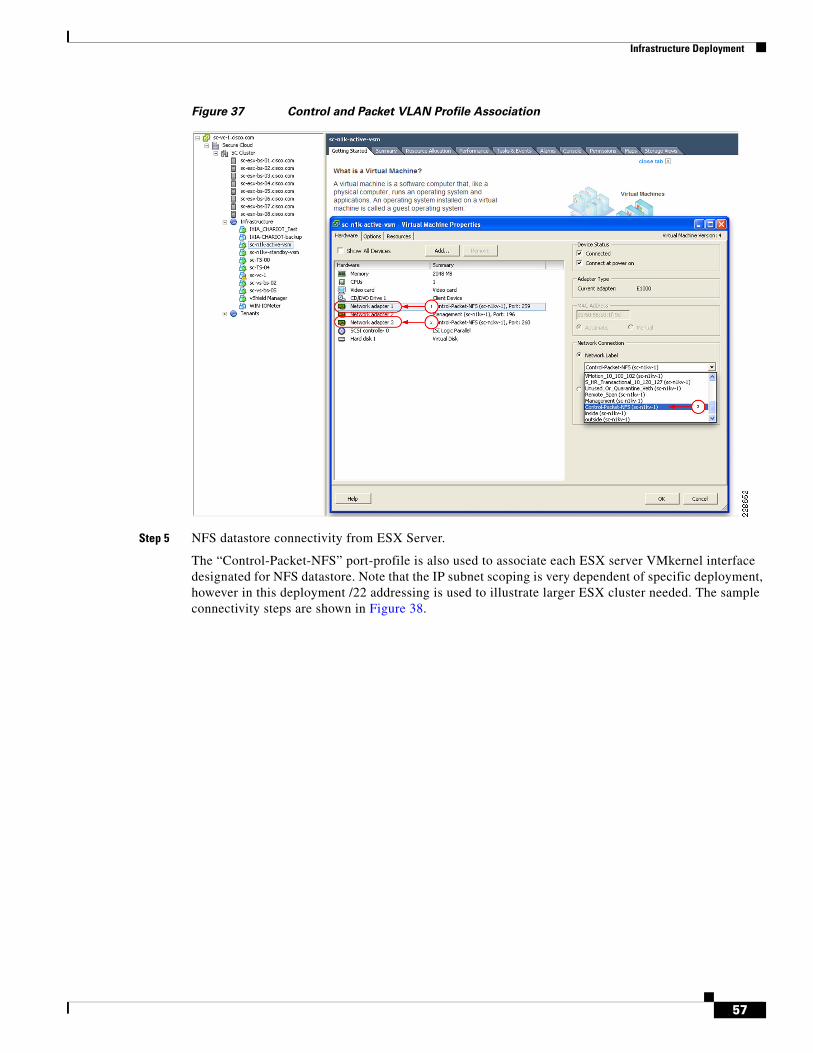
Infrastructure Deployment
Figure 37 Control and Packet VLAN Profile Association
Step 5 NFS datastore connectivity from ESX Server.
The “Control-Packet-NFS” port-profile is also used to associate each ESX server VMkernel interface designated for NFS datastore. Note that the IP subnet scoping is very dependent of specific deployment, however in this deployment /22 addressing is used to illustrate larger ESX cluster needed. The sample connectivity steps are shown in Figure 38.
57
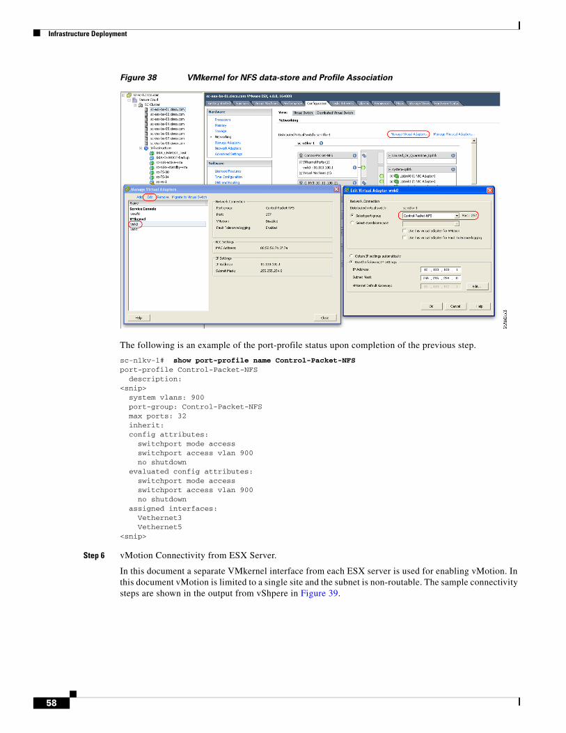
Infrastructure Deployment
Figure 38 VMkernel for NFS data-store and Profile Association
The following is an example of the port-profile status upon completion of the previous step.
sc-n1kv-1# show port-profile name Control-Packet-NFS port-profile Control-Packet-NFS description: <snip> system vlans: 900 port-group: Control-Packet-NFS max ports: 32 inherit: config attributes: switchport mode access switchport access vlan 900 no shutdown evaluated config attributes: switchport mode access switchport access vlan 900 no shutdown assigned interfaces: Vethernet3 Vethernet5 <snip>
Step 6 vMotion Connectivity from ESX Server.
In this document a separate VMkernel interface from each ESX server is used for enabling vMotion. In this document vMotion is limited to a single site and the subnet is non-routable. The sample connectivity steps are shown in the output from vShpere in Figure 39.
58
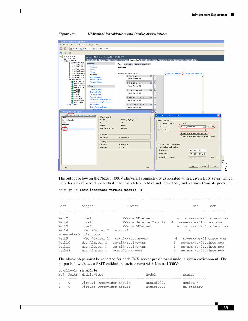
Infrastructure Deployment
Figure 39 VMkernel for vMotion and Profile Association
The output below on the Nexus 1000V shows all connectivity associated with a given ESX sever, which includes all infrastructure virtual machine vNICs, VMkernel interfaces, and Service Console ports:
sc-n1kv-1# show interface virtual module 4 ----------------------------------------------------------------------------------------------------- Port Adapter Owner Mod Host ----------------------------------------------------------------------------------------------------- Veth2 vmk1 VMware VMkernel 4 sc-esx-bs-01.cisco.com Veth4 vswif0 VMware Service Console 4 sc-esx-bs-01.cisco.com Veth5 vmk0 VMware VMkernel 4 sc-esx-bs-01.cisco.com Veth6 Net Adapter 2 sc-vc-1 4 sc-esx-bs-01.cisco.com Veth9 Net Adapter 1 sc-n1k-active-vsm 4 sc-esx-bs-01.cisco.com Veth10 Net Adapter 2 sc-n1k-active-vsm 4 sc-esx-bs-01.cisco.com Veth11 Net Adapter 3 sc-n1k-active-vsm 4 sc-esx-bs-01.cisco.com Veth48 Net Adapter 1 vShield Manager 4 sc-esx-bs-01.cisco.com
The above steps must be repeated for each ESX server provisioned under a given environment. The output below shows a SMT validation environment with Nexus 1000V:
sc-n1kv-1# sh module Mod Ports Module-Type Model Status --- ----- -------------------------------- ------------------ ------------ 1 0 Virtual Supervisor Module Nexus1000V active * 2 0 Virtual Supervisor Module Nexus1000V ha-standby
59
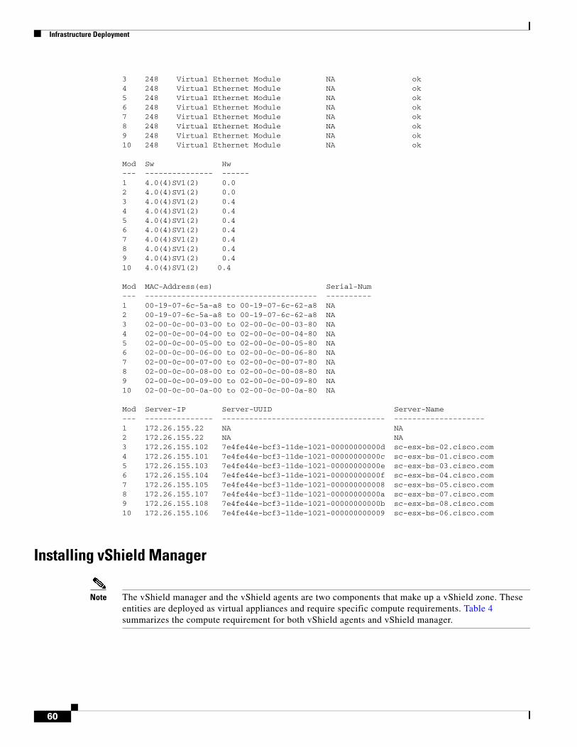
Infrastructure Deployment
3 248 Virtual Ethernet Module NA ok 4 248 Virtual Ethernet Module NA ok 5 248 Virtual Ethernet Module NA ok 6 248 Virtual Ethernet Module NA ok 7 248 Virtual Ethernet Module NA ok 8 248 Virtual Ethernet Module NA ok 9 248 Virtual Ethernet Module NA ok 10 248 Virtual Ethernet Module NA ok Mod Sw Hw --- --------------- ------ 1 4.0(4)SV1(2) 0.0 2 4.0(4)SV1(2) 0.0 3 4.0(4)SV1(2) 0.4 4 4.0(4)SV1(2) 0.4 5 4.0(4)SV1(2) 0.4 6 4.0(4)SV1(2) 0.4 7 4.0(4)SV1(2) 0.4 8 4.0(4)SV1(2) 0.4 9 4.0(4)SV1(2) 0.4 10 4.0(4)SV1(2) 0.4 Mod MAC-Address(es) Serial-Num --- -------------------------------------- ---------- 1 00-19-07-6c-5a-a8 to 00-19-07-6c-62-a8 NA 2 00-19-07-6c-5a-a8 to 00-19-07-6c-62-a8 NA 3 02-00-0c-00-03-00 to 02-00-0c-00-03-80 NA 4 02-00-0c-00-04-00 to 02-00-0c-00-04-80 NA 5 02-00-0c-00-05-00 to 02-00-0c-00-05-80 NA 6 02-00-0c-00-06-00 to 02-00-0c-00-06-80 NA 7 02-00-0c-00-07-00 to 02-00-0c-00-07-80 NA 8 02-00-0c-00-08-00 to 02-00-0c-00-08-80 NA 9 02-00-0c-00-09-00 to 02-00-0c-00-09-80 NA 10 02-00-0c-00-0a-00 to 02-00-0c-00-0a-80 NA Mod Server-IP Server-UUID Server-Name --- --------------- ------------------------------------ -------------------- 1 172.26.155.22 NA NA 2 172.26.155.22 NA NA 3 172.26.155.102 7e4fe44e-bcf3-11de-1021-00000000000d sc-esx-bs-02.cisco.com 4 172.26.155.101 7e4fe44e-bcf3-11de-1021-00000000000c sc-esx-bs-01.cisco.com 5 172.26.155.103 7e4fe44e-bcf3-11de-1021-00000000000e sc-esx-bs-03.cisco.com 6 172.26.155.104 7e4fe44e-bcf3-11de-1021-00000000000f sc-esx-bs-04.cisco.com 7 172.26.155.105 7e4fe44e-bcf3-11de-1021-000000000008 sc-esx-bs-05.cisco.com 8 172.26.155.107 7e4fe44e-bcf3-11de-1021-00000000000a sc-esx-bs-07.cisco.com 9 172.26.155.108 7e4fe44e-bcf3-11de-1021-00000000000b sc-esx-bs-08.cisco.com 10 172.26.155.106 7e4fe44e-bcf3-11de-1021-000000000009 sc-esx-bs-06.cisco.com
Installing vShield Manager
Note The vShield manager and the vShield agents are two components that make up a vShield zone. These entities are deployed as virtual appliances and require specific compute requirements. Table 4 summarizes the compute requirement for both vShield agents and vShield manager.
60
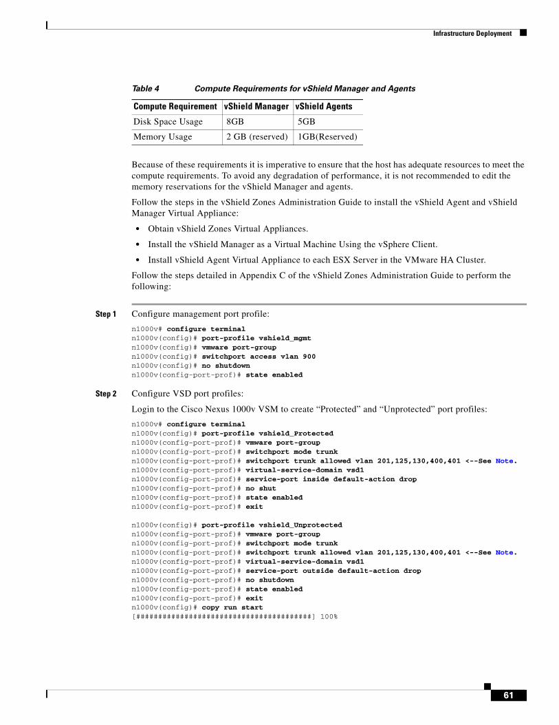
Infrastructure Deployment
Because of these requirements it is imperative to ensure that the host has adequate resources to meet the compute requirements. To avoid any degradation of performance, it is not recommended to edit the memory reservations for the vShield Manager and agents.
Follow the steps in the vShield Zones Administration Guide to install the vShield Agent and vShield Manager Virtual Appliance:
• Obtain vShield Zones Virtual Appliances.
• Install the vShield Manager as a Virtual Machine Using the vSphere Client.
• Install vShield Agent Virtual Appliance to each ESX Server in the VMware HA Cluster.
Follow the steps detailed in Appendix C of the vShield Zones Administration Guide to perform the following:
Step 1 Configure management port profile:
n1000v# configure terminal n1000v(config)# port-profile vshield_mgmt n1000v(config)# vmware port-group n1000v(config)# switchport access vlan 900 n1000v(config)# no shutdown n1000v(config-port-prof)# state enabled
Step 2 Configure VSD port profiles:
Login to the Cisco Nexus 1000v VSM to create “Protected” and “Unprotected” port profiles:
n1000v# configure terminal n1000v(config)# port-profile vshield_Protected n1000v(config-port-prof)# vmware port-group n1000v(config-port-prof)# switchport mode trunk n1000v(config-port-prof)# switchport trunk allowed vlan 201,125,130,400,401 <--See Note.n1000v(config-port-prof)# virtual-service-domain vsd1 n1000v(config-port-prof)# service-port inside default-action drop n1000v(config-port-prof)# no shut n1000v(config-port-prof)# state enabled n1000v(config-port-prof)# exit
n1000v(config)# port-profile vshield_Unprotected n1000v(config-port-prof)# vmware port-group n1000v(config-port-prof)# switchport mode trunk n1000v(config-port-prof)# switchport trunk allowed vlan 201,125,130,400,401 <--See Note.n1000v(config-port-prof)# virtual-service-domain vsd1 n1000v(config-port-prof)# service-port outside default-action drop n1000v(config-port-prof)# no shutdown n1000v(config-port-prof)# state enabled n1000v(config-port-prof)# exit n1000v(config)# copy run start [########################################] 100%
Table 4 Compute Requirements for vShield Manager and Agents
Compute Requirement vShield Manager vShield Agents
Disk Space Usage 8GB 5GB
Memory Usage 2 GB (reserved) 1GB(Reserved)
61
Infrastructure Deployment
Note Only include the VLANs that are associated with the port-profiles that correspond to virtual machines that need to be protected. To avoid network loops following a VSM reload or a network disruption, control and packet VLANS must be disabled in all vShield port profiles.
Step 3 Follow the remaining steps in the appendix to complete the following tasks:
• Deploy the vShield Manager OVF.
• Deploy the vShield Agent from OVF.
• Assign the vShield Agent Interfaces to Port Profiles.
• Set Up the vShield Agent.
• Add the vShield Agent to the vShield Manager.
Note The following steps must be followed for each vShield Zones Virtual Appliance on each ESX Server instance, given the Secure Multi-tenant Architecture is enabled with VMware HA and VMware DRS.
Step 1 Disable VMware HA or VMware DRS from moving the vShield Zones virtual appliances:
1. Log in to the vSphere Client.
2. Right-click the cluster containing your vShield Zones virtual appliances and click Edit Properties. The Admin Settings dialog box opens. Under VMware HA, click Virtual Machine Options.
3. Locate the vShield Manager and vShields in the list.
4. For each vShield Zones virtual appliance, select the following values:
– VM Restart Priority: Disabled
– Host Isolation Response: Leave VM powered on
5. Click Virtual Machine Options under VMware DRS. Locate the vShield Manager and vShields in the list.
6. For each vShield Zones virtual appliance, select Disabled for Automation Level.
7. Click OK after all vShield Zones virtual appliances have been configured.
Step 2 Enable vMotion to disable the virtual intranet check:
1. Locate the vpxd.cfg file on the machine running vCenter Server. By default, this file is installed at C:\Documents and Settings\All Users\Application Data\VMware\VMware vCenter Server.
2. Edit the vpxd.cfg file in a text editor. Add the following lines as a sub-level to the config section and at the same level as the vpxd section.
<migrate> <test> <CompatibleNetworks> <VMOnVirtualIntranet>false</VMOnVirtualIntranet> </CompatibleNetworks> </test> </migrate>
3. Save the vpxd.cfg file.
62
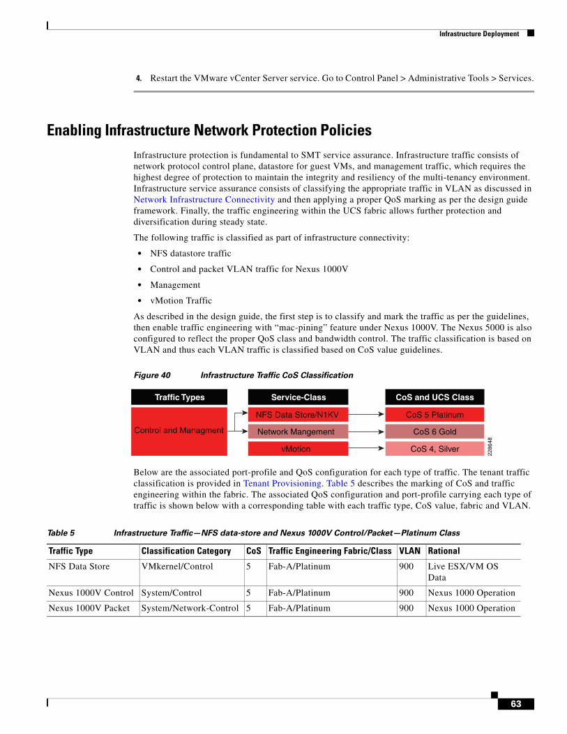
Infrastructure Deployment
4. Restart the VMware vCenter Server service. Go to Control Panel > Administrative Tools > Services.
Enabling Infrastructure Network Protection PoliciesInfrastructure protection is fundamental to SMT service assurance. Infrastructure traffic consists of network protocol control plane, datastore for guest VMs, and management traffic, which requires the highest degree of protection to maintain the integrity and resiliency of the multi-tenancy environment. Infrastructure service assurance consists of classifying the appropriate traffic in VLAN as discussed in Network Infrastructure Connectivity and then applying a proper QoS marking as per the design guide framework. Finally, the traffic engineering within the UCS fabric allows further protection and diversification during steady state.
The following traffic is classified as part of infrastructure connectivity:
• NFS datastore traffic
• Control and packet VLAN traffic for Nexus 1000V
• Management
• vMotion Traffic
As described in the design guide, the first step is to classify and mark the traffic as per the guidelines, then enable traffic engineering with “mac-pining” feature under Nexus 1000V. The Nexus 5000 is also configured to reflect the proper QoS class and bandwidth control. The traffic classification is based on VLAN and thus each VLAN traffic is classified based on CoS value guidelines.
Figure 40 Infrastructure Traffic CoS Classification
Below are the associated port-profile and QoS configuration for each type of traffic. The tenant traffic classification is provided in Tenant Provisioning. Table 5 describes the marking of CoS and traffic engineering within the fabric. The associated QoS configuration and port-profile carrying each type of traffic is shown below with a corresponding table with each traffic type, CoS value, fabric and VLAN.
Traffic Types
vMotion
Service-Class
Control and Managment
CoS 4, Silver
CoS and UCS Class
CoS 6 Gold
CoS 5 PlatinumNFS Data Store/N1KV
Network Mangement
2286
48
Table 5 Infrastructure Traffic—NFS data-store and Nexus 1000V Control/Packet—Platinum Class
Traffic Type Classification Category CoS Traffic Engineering Fabric/Class VLAN Rational
NFS Data Store VMkernel/Control 5 Fab-A/Platinum 900 Live ESX/VM OS Data
Nexus 1000V Control System/Control 5 Fab-A/Platinum 900 Nexus 1000 Operation
Nexus 1000V Packet System/Network-Control 5 Fab-A/Platinum 900 Nexus 1000 Operation
63
Infrastructure Deployment
Note For extremely high-traffic environments, in which platinum traffic may not have enough bandwidth (since in this design, UCS platinum class is bandwidth constrained because the no-drop feature is designated for Gold class and FCoE), the Nexus 1000V control and packet traffic can be classified in no-drop class to maintain connectivity between VSM and VEMs.
mac access-list control-vlans statistics per-entry 10 permit any any vlan 900 <-- NFS data-store and Nexus 1000V control/packet Traffic class-map type qos match-any Platinum_Traffic description NFS_N1kv_CtrPkt_Plat_IO_Transactional match access-group name control-vlans policy-map type qos Platinum_CoS_5 class Platinum_Traffic set cos 5
The policy map above is attached to the port-profile created earlier in Network Infrastructure Connectivity. Note that “pinning id” is used with each port-profile which enables traffic engineering with port-profile to respective fabric.
port-profile type vethernet Control-Packet-NFS switchport access vlan 900 service-policy type qos input Platinum_CoS_5 <-- Platinum service profile pinning id 0 <-- Traffic engineering pinning the traffic on Fabric A sc-n1kv-1# show port-profile name Control-Packet-NFS port-profile Control-Packet-NFS description: type: vethernet <snip> system vlans: 900 port-group: Control-Packet-NFS max ports: 32 <snip> service-policy type qos input Platinum_CoS_5 pinning id 0 no shutdown evaluated config attributes: service-policy type qos input Platinum_CoS_5 pinning id 0 no shutdown assigned interfaces: Vethernet3 Vethernet5
ip access-list mark_CoS_6 statistics per-entry 10 permit ip 172.26.155.0/25 any <-- Single VLAN identified with management
Table 6 Infrastructure Traffic—Management—Gold Class
Traffic Type Classification Category CoS Traffic Engineering Fabric/Class VLAN Rational
Nexus 1000V Management System/Control 6 Fab-B/Gold 155 Split Nexus 1000 control from Fab-A getting all
ESX Service Console vswif/Control 6 Fab-B/Gold 155 Same as above
64
Infrastructure Deployment
class-map type qos match-all Gold_Traffic match access-group name mark_CoS_6 policy-map type qos Gold_CoS_6 class Gold_Traffic set cos 6 port-profile type vethernet Management vmware port-group switchport access vlan 155 service-policy type qos input Gold_CoS_6 <-- Above policy-map is attached pinning id 1 <-- Pining for this traffic is on Fabric B
ip access-list mark_CoS_4 statistics per-entry 10 permit ip any 10.100.102.0/23 <-- vMotion subnet class-map type qos match-all Silver_Traffic match access-group name mark_CoS_4 policy-map type qos Silver_CoS_4 class Silver_Traffic set cos 4 port-profile type vethernet VMotion_10_100_102 switchport access vlan 901 service-policy type qos input Silver_Traffic <-- Policy map for silver traffic pinning id 0 <-- Traffic engineering
Additionally, one can rate-limit vMotion traffic so that it does not over-consume available bandwidth. In traditional environments, a 1Gbps interface is dedicated as the vMotion interface. In a shared environment, the vMotion interface can be restricted to 1Gbps. Note that a separate class-map is required for each type of traffic requiring policing. Thus the configuration above may change to the one below with policing.
ip access-list vMotion 10 permit ip any 10.100.102.0/23 class-map type qos match-all police_vMotion match access-group name vMotion policy-map type qos Silver_CoS_4 class police_vMotion police cir 500 mbps bc 200 ms pir 1 gbps be 200 ms conform set-cos-transmit 4 exceed set dscp dscp table cir-markdown-map violate drop table-map cir-markdown-map <-- Sample markdown map. This is specific to implementation. default copy from 1-63 to 0 <-- This will mark down all DSCP value to zero.
Notice that in example above, the vMotion traffic is sent at 500 Mbps with CoS values of 4, however after exceeding that rate the traffic is marked down with DSCP table-map to default-class. Any traffic exceeding 1 Gbps is dropped and re-transmitted by ESX server. For more information regarding
Table 7 Infrastructure Traffic—vMotion—Silver Class
Traffic Type Classification Category CoS Traffic Engineering Fabric/Class VLAN Rational
vMotion VMkernel/Control 4 Fab-A/Silver 901 Rate Limited/not often, run to completion
65
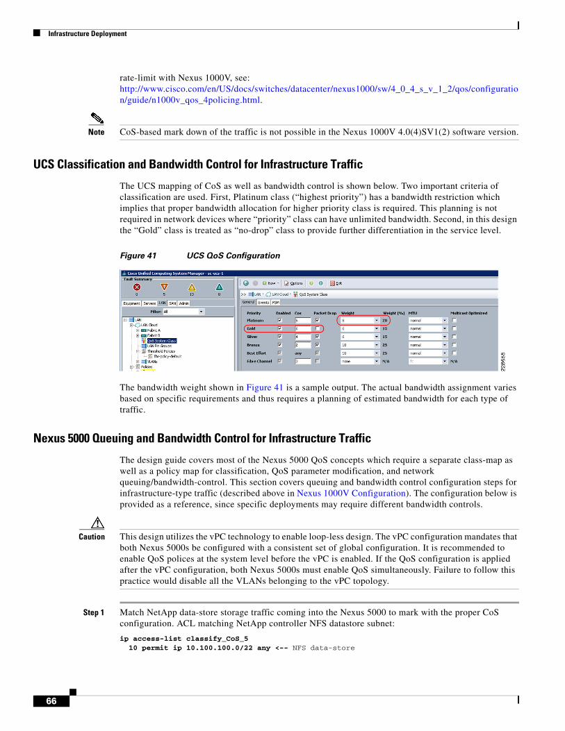
Infrastructure Deployment
rate-limit with Nexus 1000V, see: http://www.cisco.com/en/US/docs/switches/datacenter/nexus1000/sw/4_0_4_s_v_1_2/qos/configuration/guide/n1000v_qos_4policing.html.
Note CoS-based mark down of the traffic is not possible in the Nexus 1000V 4.0(4)SV1(2) software version.
UCS Classification and Bandwidth Control for Infrastructure Traffic
The UCS mapping of CoS as well as bandwidth control is shown below. Two important criteria of classification are used. First, Platinum class (“highest priority”) has a bandwidth restriction which implies that proper bandwidth allocation for higher priority class is required. This planning is not required in network devices where “priority” class can have unlimited bandwidth. Second, in this design the “Gold” class is treated as “no-drop” class to provide further differentiation in the service level.
Figure 41 UCS QoS Configuration
The bandwidth weight shown in Figure 41 is a sample output. The actual bandwidth assignment varies based on specific requirements and thus requires a planning of estimated bandwidth for each type of traffic.
Nexus 5000 Queuing and Bandwidth Control for Infrastructure Traffic
The design guide covers most of the Nexus 5000 QoS concepts which require a separate class-map as well as a policy map for classification, QoS parameter modification, and network queuing/bandwidth-control. This section covers queuing and bandwidth control configuration steps for infrastructure-type traffic (described above in Nexus 1000V Configuration). The configuration below is provided as a reference, since specific deployments may require different bandwidth controls.
Caution This design utilizes the vPC technology to enable loop-less design. The vPC configuration mandates that both Nexus 5000s be configured with a consistent set of global configuration. It is recommended to enable QoS polices at the system level before the vPC is enabled. If the QoS configuration is applied after the vPC configuration, both Nexus 5000s must enable QoS simultaneously. Failure to follow this practice would disable all the VLANs belonging to the vPC topology.
Step 1 Match NetApp data-store storage traffic coming into the Nexus 5000 to mark with the proper CoS configuration. ACL matching NetApp controller NFS datastore subnet:
ip access-list classify_CoS_5 10 permit ip 10.100.100.0/22 any <-- NFS data-store
66
Infrastructure Deployment
Step 2 Listed below are the class-maps for NetApp controller traffic and ACL attachments:
class-map type qos Platinum_Traffic <-- Class-map is of "qos" type match access-group name classify_CoS_5
Step 3 Listed below are the class maps for classifying any traffic within qos group which is marked at the boundary either originating from the Nexus 1000V or Nexus 7000. This will match CoS set for NFS datastore from the VM, Nexus 1000V packet/control, and management VLAN traffic. The class-map below serves two functions: first it matches infrastructure traffic and second the same class-map is used for matching the traffic for the tenants.
class-map type qos Platinum_transactional match cos 5 class-map type qos Gold_Transactional match cos 6 class-map type qos Silver_Transactional match cos 4
Step 4 Configure the qos-group to tie the classifier (qos) to the network-qos operation. The configuration below assigns the qos group number (2-5) to the set of traffic, e.g., cos 5 is group 2, which is platinum class. This qos-group is used for matching the infrastructure traffic originating from the VM, ESX, and UCS.
policy-map type qos Global_Classify_NFS_Application <-- policy-map of "qos" type class Platinum_Traffic set qos-group 2 class Platinum_transactional set qos-group 2 class Gold_Transactional set qos-group 3 class Silver_Transactional set qos-group 4
Step 5 The configuration below matches the CoS for NetApp traffic coming from storage which was classified with the above qos-group. The class-map and policy-may of type “network-qos” are required for changing the QoS parameter.
class-map type network-qos Platinum_Traffic_NQ <-- The class-map of type "network-qos" match qos-group 2
Step 6 The policy-map below uses the above class-map to set the CoS value for NFS.
policy-map type network-qos Netapp_Qos class type network-qos Platinum_Traffic_NQ set cos 5 queue-limit 30000 bytes <-- Queue limit is used to distribute the buffer evenly
Step 7 The “queuing” class-map is required to properly queue the traffic. Again the qos-group is used to tie things together. Note that the class-map below has a dual purpose: first it queues the traffic already marked with Nexus 1000V and second it is used for traffic marked by Nexus 5000 “qos” classifier for traffic originating from NetApp controller. Thus this queuing class will also be used in tenant services protection provisioning.
class-map type queuing Platinum_Traffic_Q match qos-group 2 class-map type queuing Gold_Traffic_Q match qos-group 3 class-map type queuing Silver_Traffic_Q match qos-group 4
Step 8 BW Control for the given queue is defined in policy-map of type “queuing”:
policy-map type queuing Global_BW_Queuing class type queuing Platinum_Traffic_Q
67
Infrastructure Deployment
priority class type queuing Gold_Traffic_Q bandwidth percent 20 class type queuing Silver_Traffic_Q bandwidth percent 15
Warning The above bandwidth allocation is a sample configuration. For a given deployment proper bandwidth allocation must be planned based on NFS data-store traffic requirement along with tenant traffic allocated to each class as per policy.
Step 9 Finally globally enable the QoS framework of classifier, network-qos, and queuing with the following system-level CLI:
system qos service-policy type queuing output Global_BW_Queuing <-- Enable global queuing service-policy type qos input Global_Classify_NFS_Application <-- Enable global classifier service-policy type network-qos Netapp_Qos <-- Enable QoS parameter setting
The Nexus 7000 QoS control and policy management is beyond the scope and applicability of this deployment guide and thus not covered here. Although validation traffic marked with DSCP value was automatically converted to respective CoS value with the Nexus 7000.
Deploying NetApp Operations Manager and Provisioning ManagerThe next step is to deploy NetApp Operations Manager and Provisioning Manager inside a virtual machine within the environment. NetApp Operations Manager and Provisioning Manager are components of the NetApp DataFabric Manager server, which can be obtained from the NetApp NOW Support and Services site (http://now.netapp.com). Follow the accompanying documentation for best practice installation procedures.
NetApp Provisioning Manager provides policy-based automation for deploying and managing storage resources. Because the manual creation of storage was necessary before Provisioning Manager was available (to load ESX and create initial virtual machines), these pre-existing storage objects should be imported into Provisioning Manager as datasets in order to be managed by the software. A dataset is a collection of user data, including replicas of that data, that is managed as a single entity. Policies are applied to datasets to define how the members are provisioned and managed. The following sections outline these procedures:
• Creating the Infrastructure Storage Resource Pool—A resource pool is a collection of storage systems or containers used to provision datasets. Storage from both “NetApp1” and “NetApp2” systems are assigned to a resource pool for further storage provisioning to the environment.
• Creating Infrastructure Provisioning Policies—VMware best practices recommend limits on the number of VMs per datastore; therefore, additional NFS datastores (Flexible volumes) must be provisioned as the environment scales out. Provisioning Manager enforces policies that govern how additional NFS datastores are deployed to enable standardization and storage management best practices.
• Creating Infrastructure Datasets—The infrastructure datasets consist of all the NFS datastores deployed in the environment. Two datasets are created to contain all NFS datastores created on “NetApp1” and “NetApp2”.
68
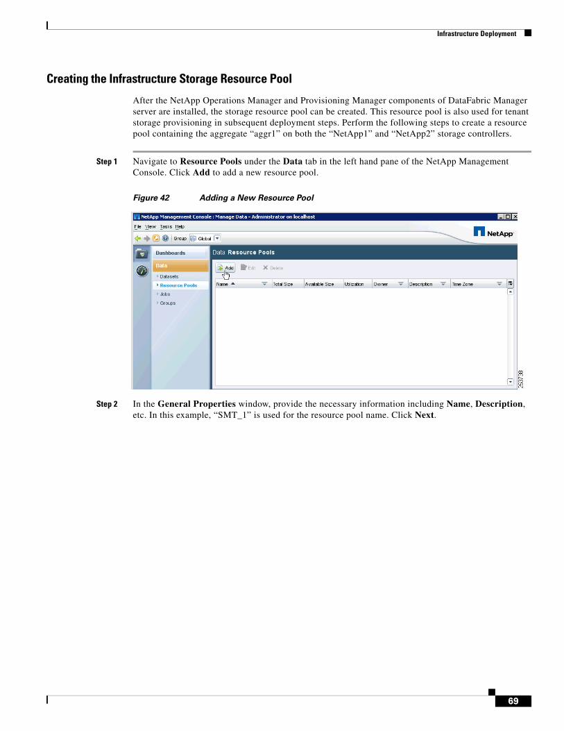
Infrastructure Deployment
Creating the Infrastructure Storage Resource Pool
After the NetApp Operations Manager and Provisioning Manager components of DataFabric Manager server are installed, the storage resource pool can be created. This resource pool is also used for tenant storage provisioning in subsequent deployment steps. Perform the following steps to create a resource pool containing the aggregate “aggr1” on both the “NetApp1” and “NetApp2” storage controllers.
Step 1 Navigate to Resource Pools under the Data tab in the left hand pane of the NetApp Management Console. Click Add to add a new resource pool.
Figure 42 Adding a New Resource Pool
Step 2 In the General Properties window, provide the necessary information including Name, Description, etc. In this example, “SMT_1” is used for the resource pool name. Click Next.
69
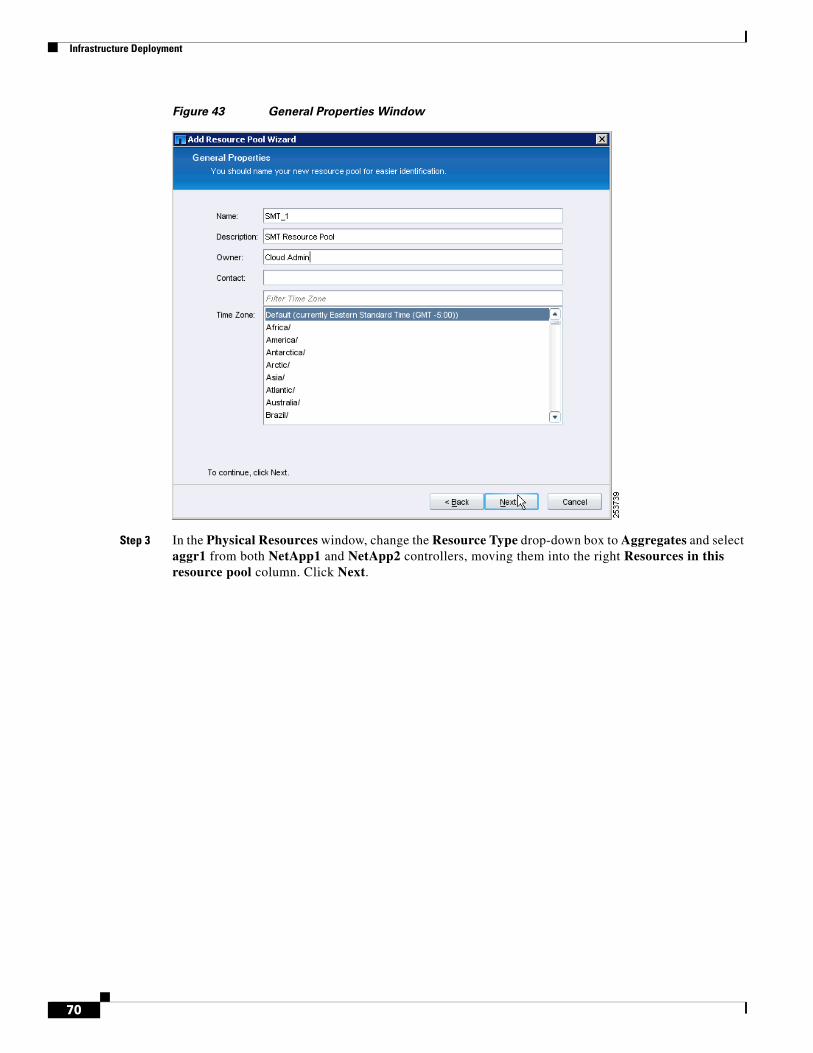
Infrastructure Deployment
Figure 43 General Properties Window
Step 3 In the Physical Resources window, change the Resource Type drop-down box to Aggregates and select aggr1 from both NetApp1 and NetApp2 controllers, moving them into the right Resources in this resource pool column. Click Next.
70
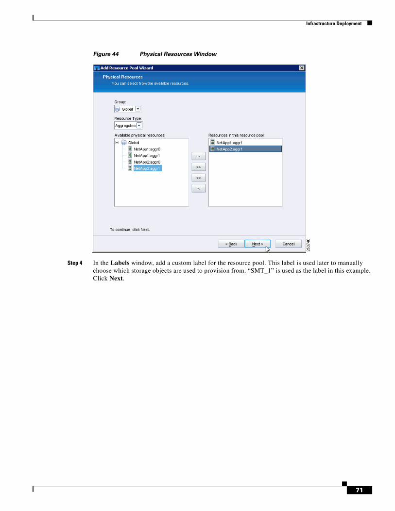
Infrastructure Deployment
Figure 44 Physical Resources Window
Step 4 In the Labels window, add a custom label for the resource pool. This label is used later to manually choose which storage objects are used to provision from. “SMT_1” is used as the label in this example. Click Next.
71
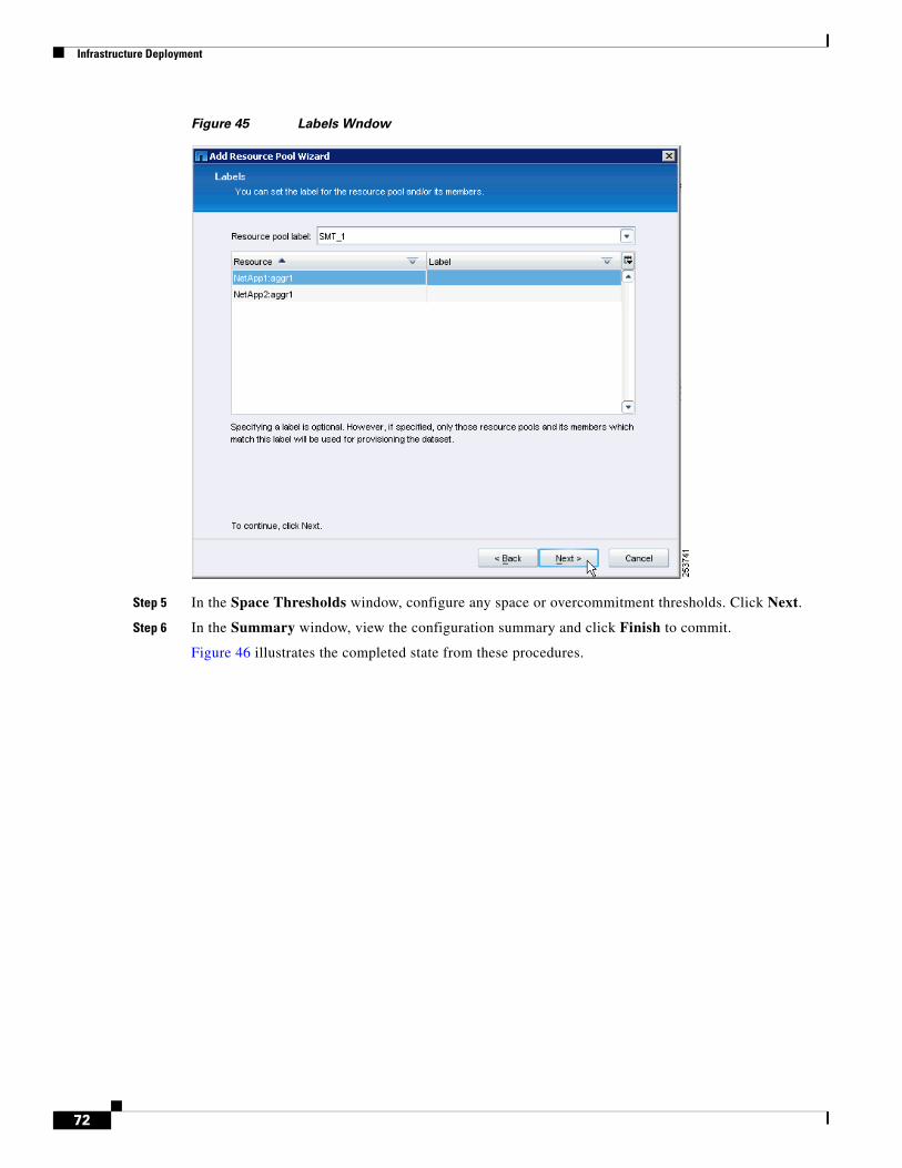
Infrastructure Deployment
Figure 45 Labels Wndow
Step 5 In the Space Thresholds window, configure any space or overcommitment thresholds. Click Next.
Step 6 In the Summary window, view the configuration summary and click Finish to commit.
Figure 46 illustrates the completed state from these procedures.
72
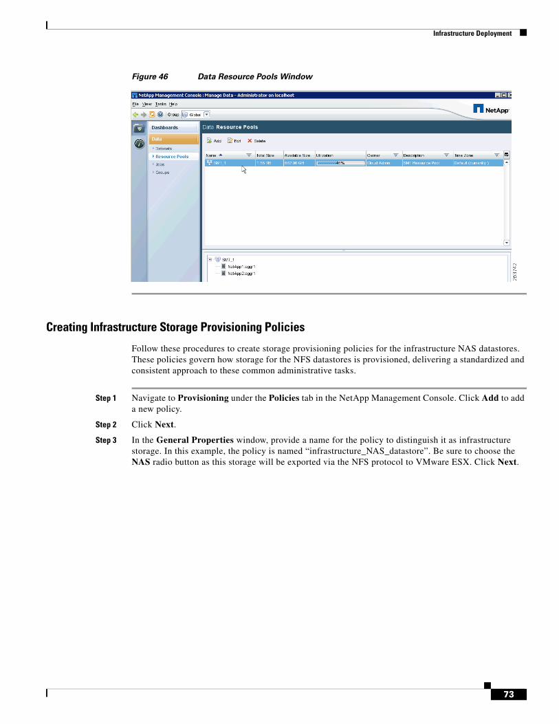
Infrastructure Deployment
Figure 46 Data Resource Pools Window
Creating Infrastructure Storage Provisioning Policies
Follow these procedures to create storage provisioning policies for the infrastructure NAS datastores. These policies govern how storage for the NFS datastores is provisioned, delivering a standardized and consistent approach to these common administrative tasks.
Step 1 Navigate to Provisioning under the Policies tab in the NetApp Management Console. Click Add to add a new policy.
Step 2 Click Next.
Step 3 In the General Properties window, provide a name for the policy to distinguish it as infrastructure storage. In this example, the policy is named “infrastructure_NAS_datastore”. Be sure to choose the NAS radio button as this storage will be exported via the NFS protocol to VMware ESX. Click Next.
73
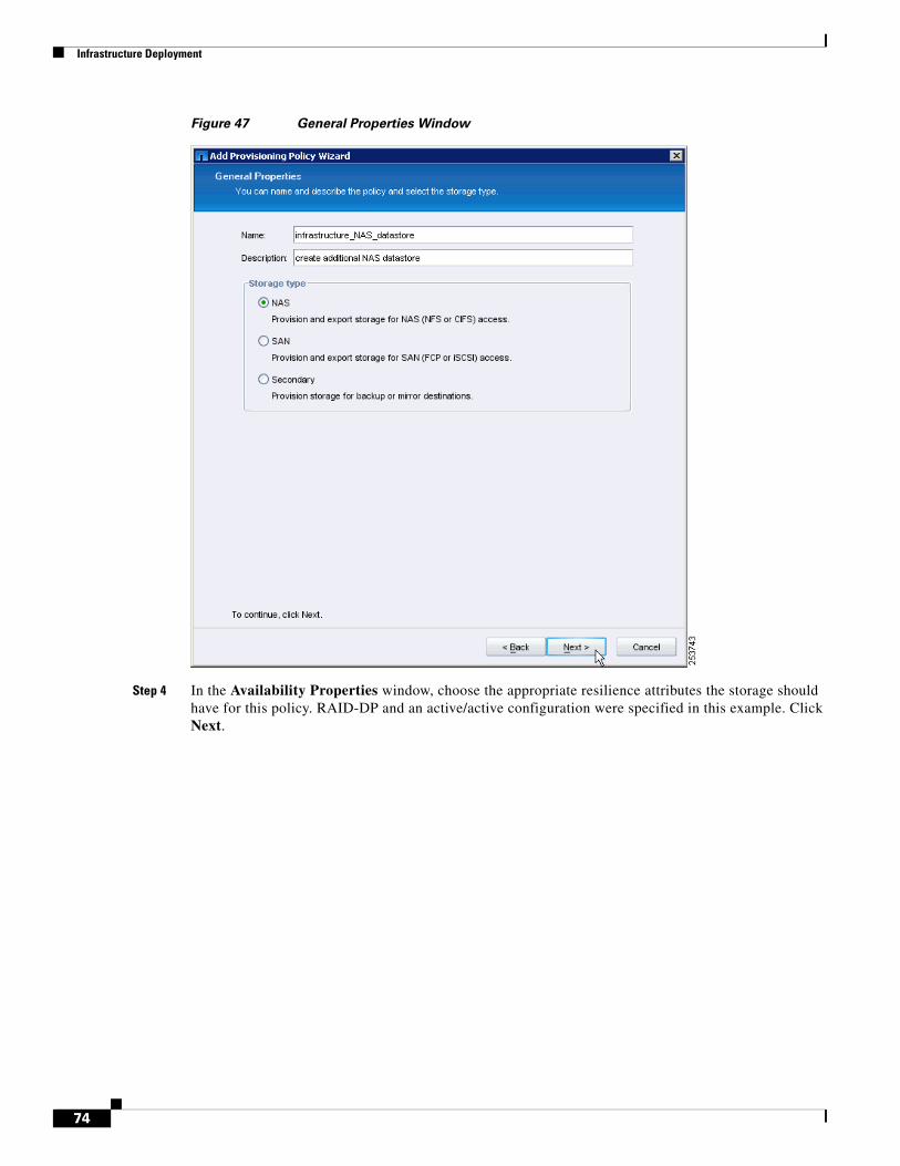
Infrastructure Deployment
Figure 47 General Properties Window
Step 4 In the Availability Properties window, choose the appropriate resilience attributes the storage should have for this policy. RAID-DP and an active/active configuration were specified in this example. Click Next.
74
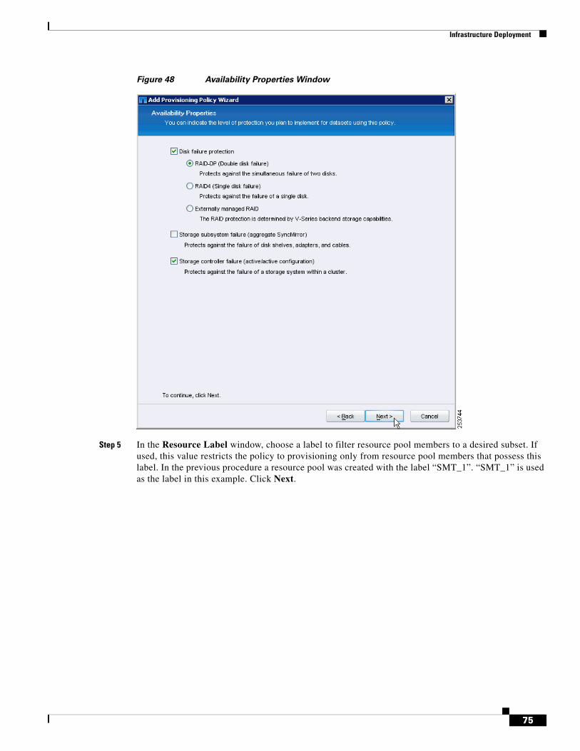
Infrastructure Deployment
Figure 48 Availability Properties Window
Step 5 In the Resource Label window, choose a label to filter resource pool members to a desired subset. If used, this value restricts the policy to provisioning only from resource pool members that possess this label. In the previous procedure a resource pool was created with the label “SMT_1”. “SMT_1” is used as the label in this example. Click Next.
75
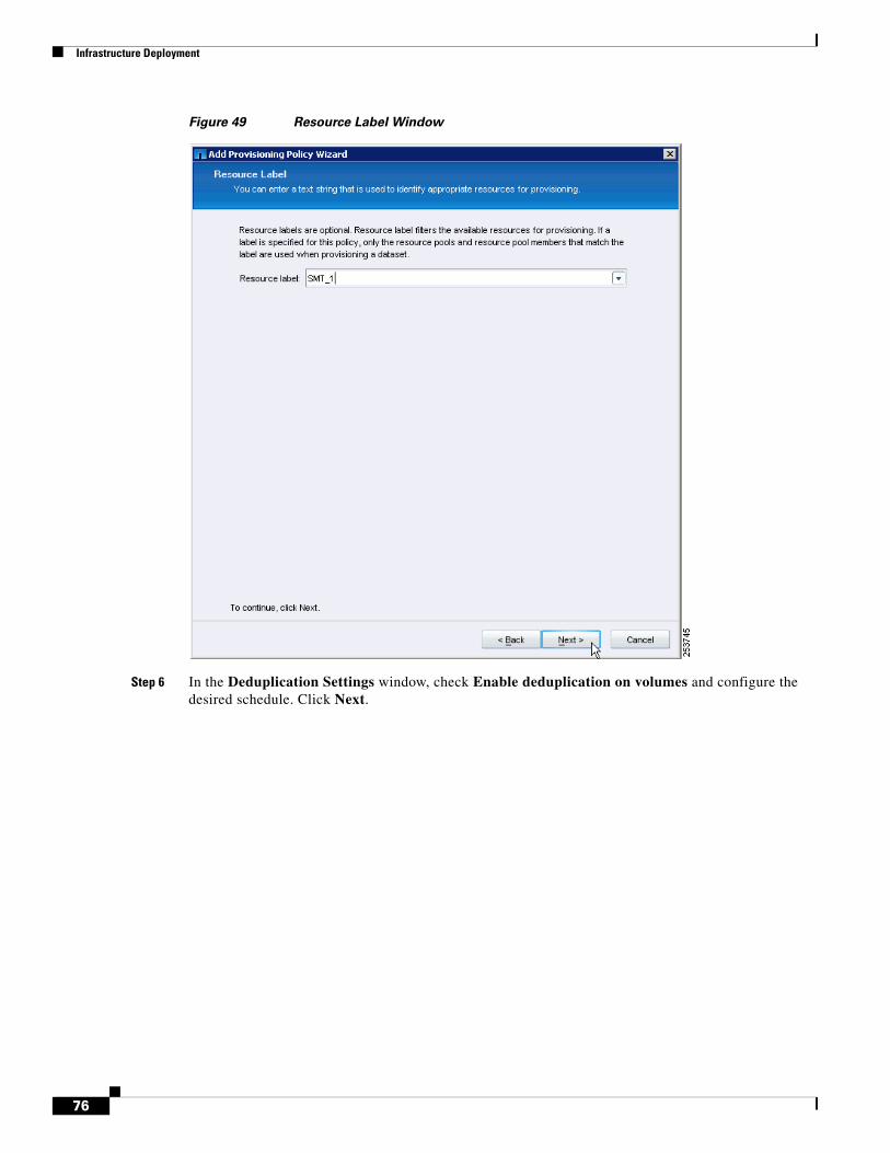
Infrastructure Deployment
Figure 49 Resource Label Window
Step 6 In the Deduplication Settings window, check Enable deduplication on volumes and configure the desired schedule. Click Next.
76
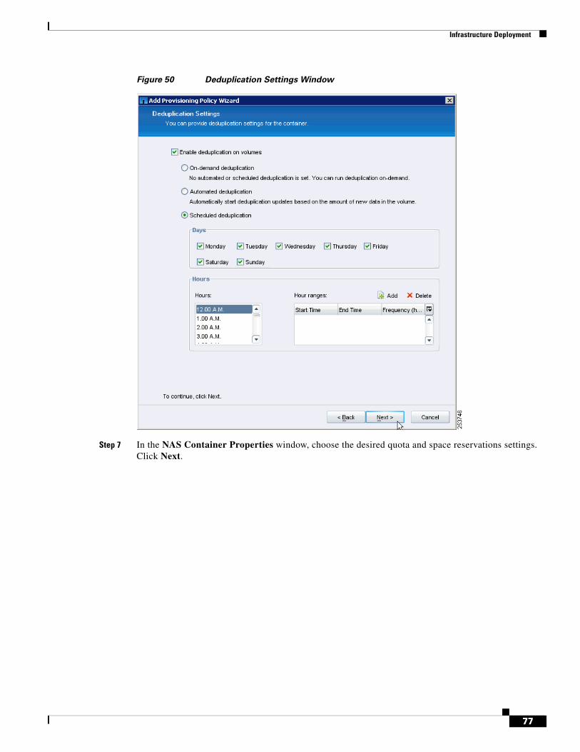
Infrastructure Deployment
Figure 50 Deduplication Settings Window
Step 7 In the NAS Container Properties window, choose the desired quota and space reservations settings. Click Next.
77
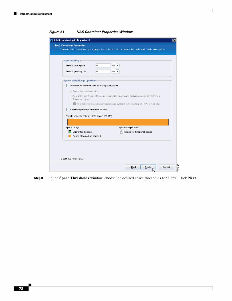
Infrastructure Deployment
Figure 51 NAS Container Properties Window
Step 8 In the Space Thresholds window, choose the desired space thresholds for alerts. Click Next.
78
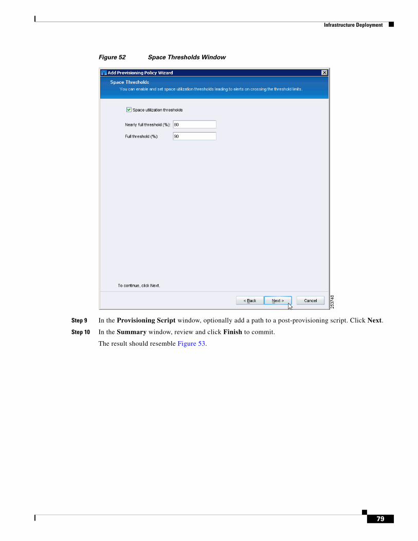
Infrastructure Deployment
Figure 52 Space Thresholds Window
Step 9 In the Provisioning Script window, optionally add a path to a post-provisioning script. Click Next.
Step 10 In the Summary window, review and click Finish to commit.
The result should resemble Figure 53.
79
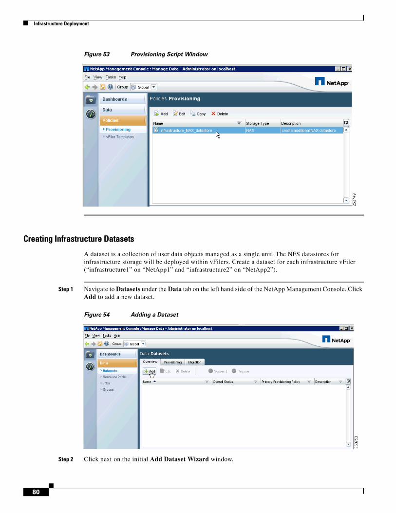
Infrastructure Deployment
Figure 53 Provisioning Script Window
Creating Infrastructure Datasets
A dataset is a collection of user data objects managed as a single unit. The NFS datastores for infrastructure storage will be deployed within vFilers. Create a dataset for each infrastructure vFiler (“infrastructure1” on “NetApp1” and “infrastructure2” on “NetApp2”).
Step 1 Navigate to Datasets under the Data tab on the left hand side of the NetApp Management Console. Click Add to add a new dataset.
Figure 54 Adding a Dataset
Step 2 Click next on the initial Add Dataset Wizard window.
80
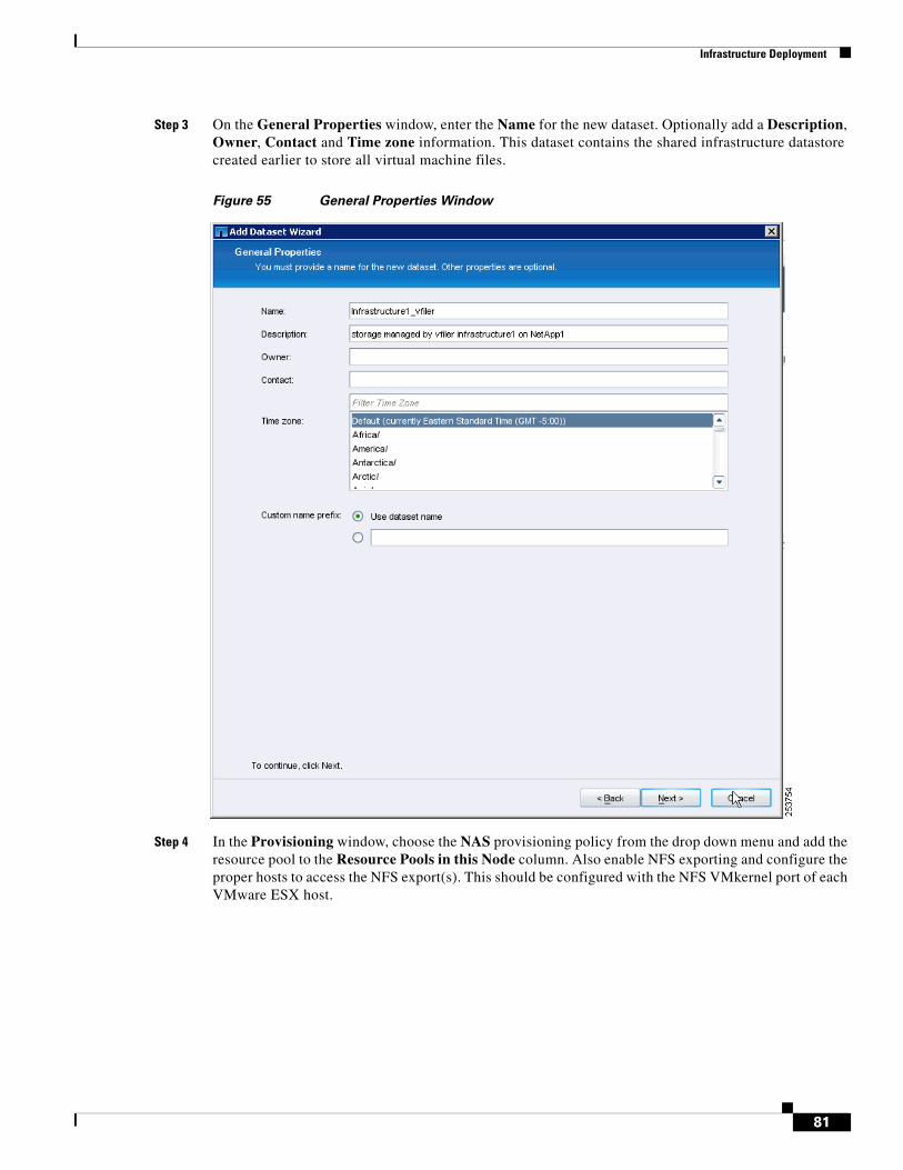
Infrastructure Deployment
Step 3 On the General Properties window, enter the Name for the new dataset. Optionally add a Description, Owner, Contact and Time zone information. This dataset contains the shared infrastructure datastore created earlier to store all virtual machine files.
Figure 55 General Properties Window
Step 4 In the Provisioning window, choose the NAS provisioning policy from the drop down menu and add the resource pool to the Resource Pools in this Node column. Also enable NFS exporting and configure the proper hosts to access the NFS export(s). This should be configured with the NFS VMkernel port of each VMware ESX host.
81
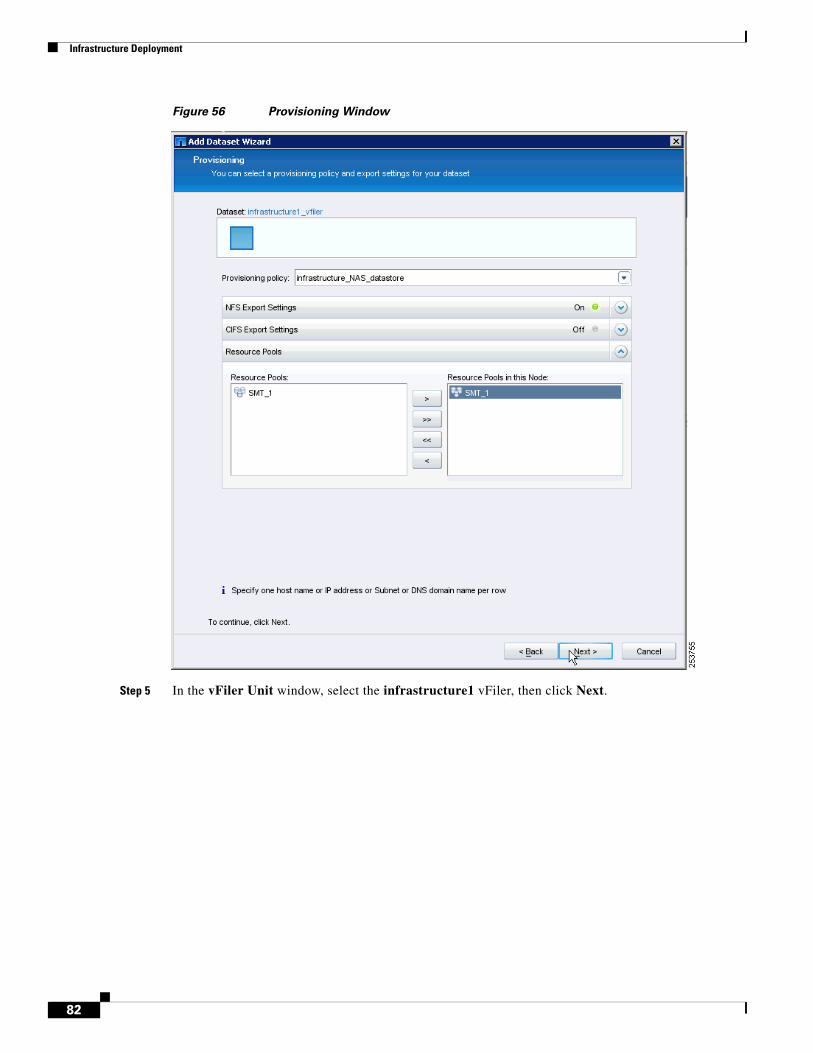
Infrastructure Deployment
Figure 56 Provisioning Window
Step 5 In the vFiler Unit window, select the infrastructure1 vFiler, then click Next.
82
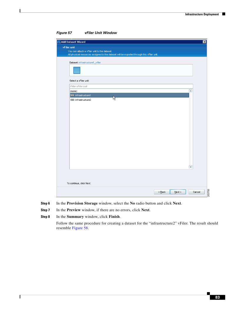
Infrastructure Deployment
Figure 57 vFiler Unit Window
Step 6 In the Provision Storage window, select the No radio button and click Next.
Step 7 In the Preview window, if there are no errors, click Next.
Step 8 In the Summary window, click Finish.
Follow the same procedure for creating a dataset for the “infrastructure2” vFiler. The result should resemble Figure 58.
83
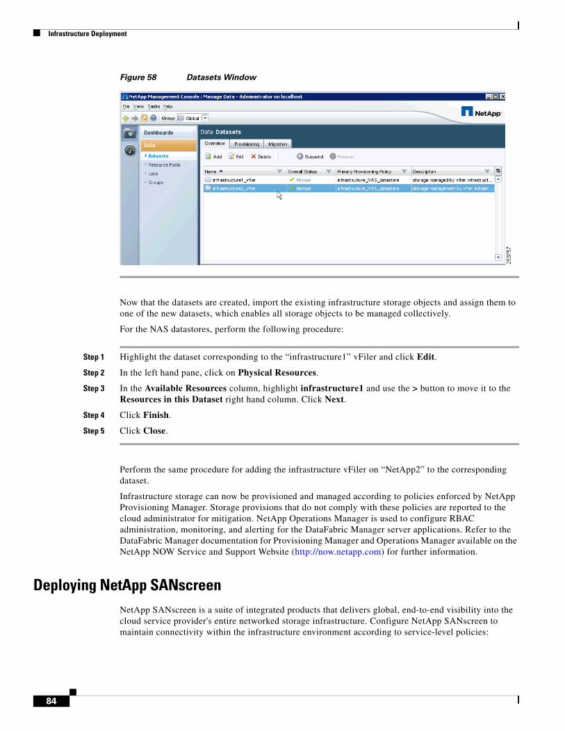
Infrastructure Deployment
Figure 58 Datasets Window
Now that the datasets are created, import the existing infrastructure storage objects and assign them to one of the new datasets, which enables all storage objects to be managed collectively.
For the NAS datastores, perform the following procedure:
Step 1 Highlight the dataset corresponding to the “infrastructure1” vFiler and click Edit.
Step 2 In the left hand pane, click on Physical Resources.
Step 3 In the Available Resources column, highlight infrastructure1 and use the > button to move it to the Resources in this Dataset right hand column. Click Next.
Step 4 Click Finish.
Step 5 Click Close.
Perform the same procedure for adding the infrastructure vFiler on “NetApp2” to the corresponding dataset.
Infrastructure storage can now be provisioned and managed according to policies enforced by NetApp Provisioning Manager. Storage provisions that do not comply with these policies are reported to the cloud administrator for mitigation. NetApp Operations Manager is used to configure RBAC administration, monitoring, and alerting for the DataFabric Manager server applications. Refer to the DataFabric Manager documentation for Provisioning Manager and Operations Manager available on the NetApp NOW Service and Support Website (http://now.netapp.com) for further information.
Deploying NetApp SANscreenNetApp SANscreen is a suite of integrated products that delivers global, end-to-end visibility into the cloud service provider's entire networked storage infrastructure. Configure NetApp SANscreen to maintain connectivity within the infrastructure environment according to service-level policies:
84
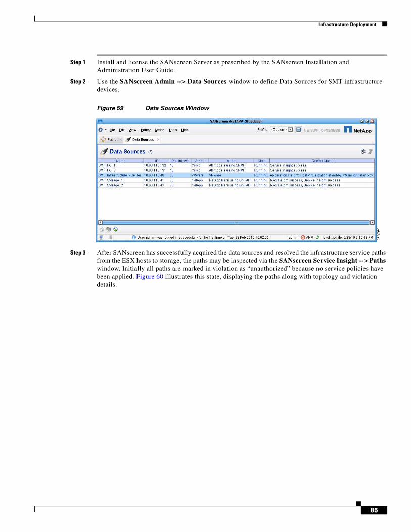
Infrastructure Deployment
Step 1 Install and license the SANscreen Server as prescribed by the SANscreen Installation and Administration User Guide.
Step 2 Use the SANscreen Admin --> Data Sources window to define Data Sources for SMT infrastructure devices.
Figure 59 Data Sources Window
Step 3 After SANscreen has successfully acquired the data sources and resolved the infrastructure service paths from the ESX hosts to storage, the paths may be inspected via the SANscreen Service Insight --> Paths window. Initially all paths are marked in violation as “unauthorized” because no service policies have been applied. Figure 60 illustrates this state, displaying the paths along with topology and violation details.
85
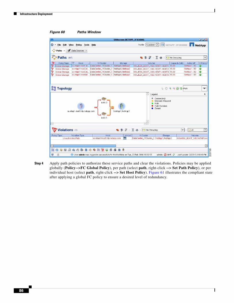
Infrastructure Deployment
Figure 60 Paths Window
Step 4 Apply path policies to authorize these service paths and clear the violations. Policies may be applied globally (Policy-->FC Global Policy), per path (select path, right-click --> Set Path Policy), or per individual host (select path, right-click --> Set Host Policy). Figure 61 illustrates the compliant state after applying a global FC policy to ensure a desired level of redundancy.
86
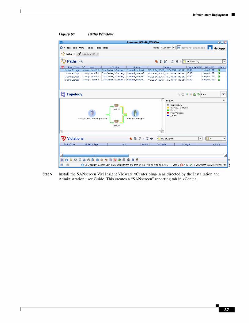
Infrastructure Deployment
Figure 61 Paths Window
Step 5 Install the SANscreen VM Insight VMware vCenter plug-in as directed by the Installation and Administration user Guide. This creates a “SANscreen” reporting tab in vCenter.
87
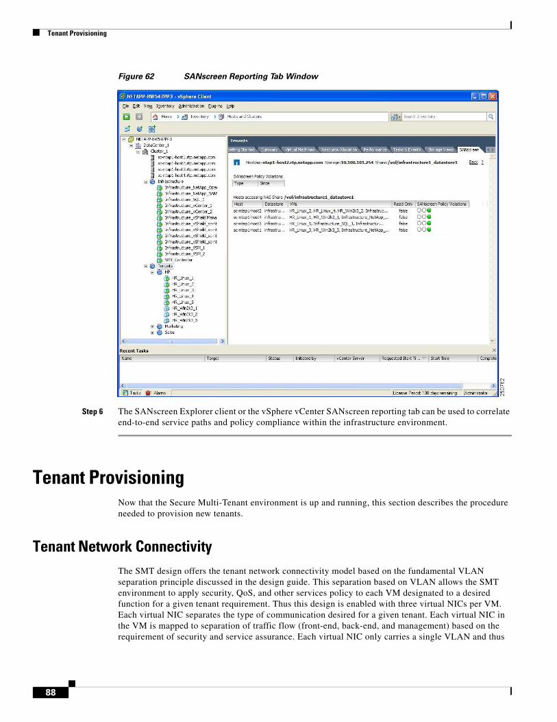
Tenant Provisioning
Figure 62 SANscreen Reporting Tab Window
Step 6 The SANscreen Explorer client or the vSphere vCenter SANscreen reporting tab can be used to correlate end-to-end service paths and policy compliance within the infrastructure environment.
Tenant ProvisioningNow that the Secure Multi-Tenant environment is up and running, this section describes the procedure needed to provision new tenants.
Tenant Network ConnectivityThe SMT design offers the tenant network connectivity model based on the fundamental VLAN separation principle discussed in the design guide. This separation based on VLAN allows the SMT environment to apply security, QoS, and other services policy to each VM designated to a desired function for a given tenant requirement. Thus this design is enabled with three virtual NICs per VM. Each virtual NIC separates the type of communication desired for a given tenant. Each virtual NIC in the VM is mapped to separation of traffic flow (front-end, back-end, and management) based on the requirement of security and service assurance. Each virtual NIC only carries a single VLAN and thus
88
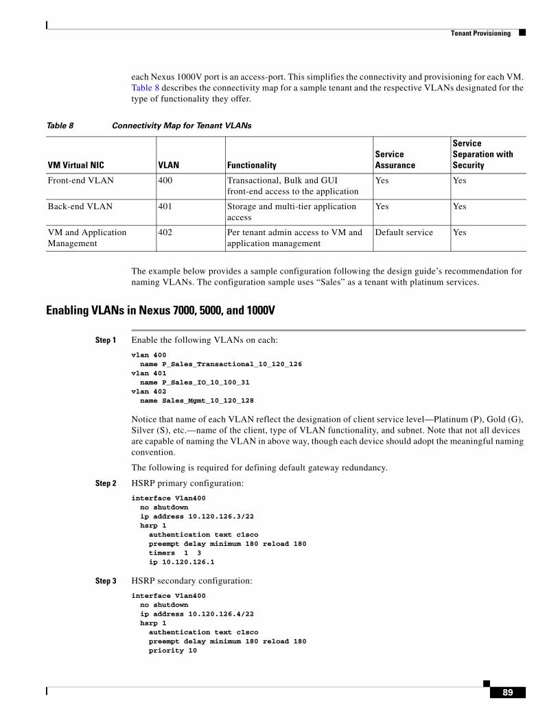
Tenant Provisioning
each Nexus 1000V port is an access-port. This simplifies the connectivity and provisioning for each VM. Table 8 describes the connectivity map for a sample tenant and the respective VLANs designated for the type of functionality they offer.
The example below provides a sample configuration following the design guide’s recommendation for naming VLANs. The configuration sample uses “Sales” as a tenant with platinum services.
Enabling VLANs in Nexus 7000, 5000, and 1000V
Step 1 Enable the following VLANs on each:
vlan 400 name P_Sales_Transactional_10_120_126 vlan 401 name P_Sales_IO_10_100_31 vlan 402 name Sales_Mgmt_10_120_128
Notice that name of each VLAN reflect the designation of client service level—Platinum (P), Gold (G), Silver (S), etc.—name of the client, type of VLAN functionality, and subnet. Note that not all devices are capable of naming the VLAN in above way, though each device should adopt the meaningful naming convention.
The following is required for defining default gateway redundancy.
Step 2 HSRP primary configuration:
interface Vlan400 no shutdown ip address 10.120.126.3/22 hsrp 1 authentication text c1sco preempt delay minimum 180 reload 180 timers 1 3 ip 10.120.126.1
Step 3 HSRP secondary configuration:
interface Vlan400 no shutdown ip address 10.120.126.4/22 hsrp 1 authentication text c1sco preempt delay minimum 180 reload 180 priority 10
Table 8 Connectivity Map for Tenant VLANs
VM Virtual NIC VLAN FunctionalityService Assurance
Service Separation with Security
Front-end VLAN 400 Transactional, Bulk and GUI front-end access to the application
Yes Yes
Back-end VLAN 401 Storage and multi-tier application access
Yes Yes
VM and Application Management
402 Per tenant admin access to VM and application management
Default service Yes
89
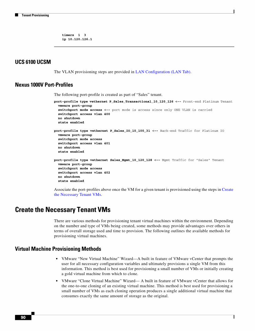
Tenant Provisioning
timers 1 3 ip 10.120.126.1
UCS 6100 UCSM
The VLAN provisioning steps are provided in LAN Configuration (LAN Tab).
Nexus 1000V Port-Profiles
The following port-profile is created as part of “Sales” tenant.
port-profile type vethernet P_Sales_Transactional_10_120_126 <-- Front-end Platinum Tenant vmware port-group switchport mode access <-- port mode is access since only ONE VLAN is carried switchport access vlan 400 no shutdown state enabled port-profile type vethernet P_Sales_IO_10_100_31 <-- Back-end Traffic for Platinum IO vmware port-group switchport mode access switchport access vlan 401 no shutdown state enabled port-profile type vethernet Sales_Mgmt_10_120_128 <-- Mgmt Traffic for "Sales" Tenant vmware port-group switchport mode access switchport access vlan 402 no shutdown state enabled
Associate the port-profiles above once the VM for a given tenant is provisioned using the steps in Create the Necessary Tenant VMs.
Create the Necessary Tenant VMsThere are various methods for provisioning tenant virtual machines within the environment. Depending on the number and type of VMs being created, some methods may provide advantages over others in terms of overall storage used and time to provision. The following outlines the available methods for provisioning virtual machines.
Virtual Machine Provisioning Methods
• VMware “New Virtual Machine” Wizard—A built in feature of VMware vCenter that prompts the user for all necessary configuration variables and ultimately provisions a single VM from this information. This method is best used for provisioning a small number of VMs or initially creating a gold virtual machine from which to clone.
• VMware “Clone Virtual Machine” Wizard— A built in feature of VMware vCenter that allows for the one-to-one cloning of an existing virtual machine. This method is best used for provisioning a small number of VMs as each cloning operation produces a single additional virtual machine that consumes exactly the same amount of storage as the original.
90
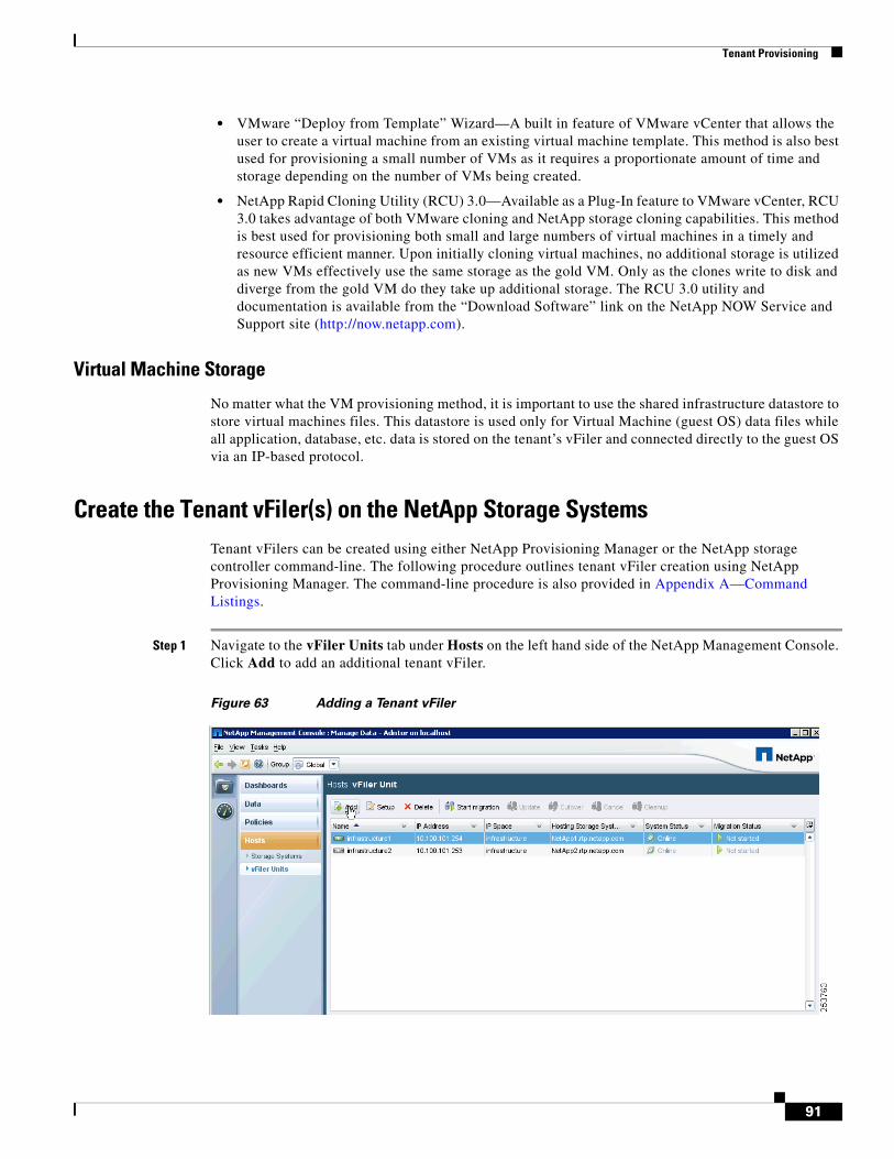
Tenant Provisioning
• VMware “Deploy from Template” Wizard—A built in feature of VMware vCenter that allows the user to create a virtual machine from an existing virtual machine template. This method is also best used for provisioning a small number of VMs as it requires a proportionate amount of time and storage depending on the number of VMs being created.
• NetApp Rapid Cloning Utility (RCU) 3.0—Available as a Plug-In feature to VMware vCenter, RCU 3.0 takes advantage of both VMware cloning and NetApp storage cloning capabilities. This method is best used for provisioning both small and large numbers of virtual machines in a timely and resource efficient manner. Upon initially cloning virtual machines, no additional storage is utilized as new VMs effectively use the same storage as the gold VM. Only as the clones write to disk and diverge from the gold VM do they take up additional storage. The RCU 3.0 utility and documentation is available from the “Download Software” link on the NetApp NOW Service and Support site (http://now.netapp.com).
Virtual Machine Storage
No matter what the VM provisioning method, it is important to use the shared infrastructure datastore to store virtual machines files. This datastore is used only for Virtual Machine (guest OS) data files while all application, database, etc. data is stored on the tenant’s vFiler and connected directly to the guest OS via an IP-based protocol.
Create the Tenant vFiler(s) on the NetApp Storage SystemsTenant vFilers can be created using either NetApp Provisioning Manager or the NetApp storage controller command-line. The following procedure outlines tenant vFiler creation using NetApp Provisioning Manager. The command-line procedure is also provided in Appendix A—Command Listings.
Step 1 Navigate to the vFiler Units tab under Hosts on the left hand side of the NetApp Management Console. Click Add to add an additional tenant vFiler.
Figure 63 Adding a Tenant vFiler
91
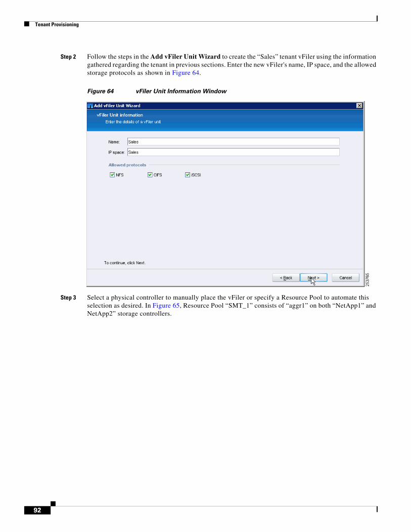
Tenant Provisioning
Step 2 Follow the steps in the Add vFiler Unit Wizard to create the “Sales” tenant vFiler using the information gathered regarding the tenant in previous sections. Enter the new vFiler's name, IP space, and the allowed storage protocols as shown in Figure 64.
Figure 64 vFiler Unit Information Window
Step 3 Select a physical controller to manually place the vFiler or specify a Resource Pool to automate this selection as desired. In Figure 65, Resource Pool “SMT_1” consists of “aggr1” on both “NetApp1” and NetApp2” storage controllers.
92
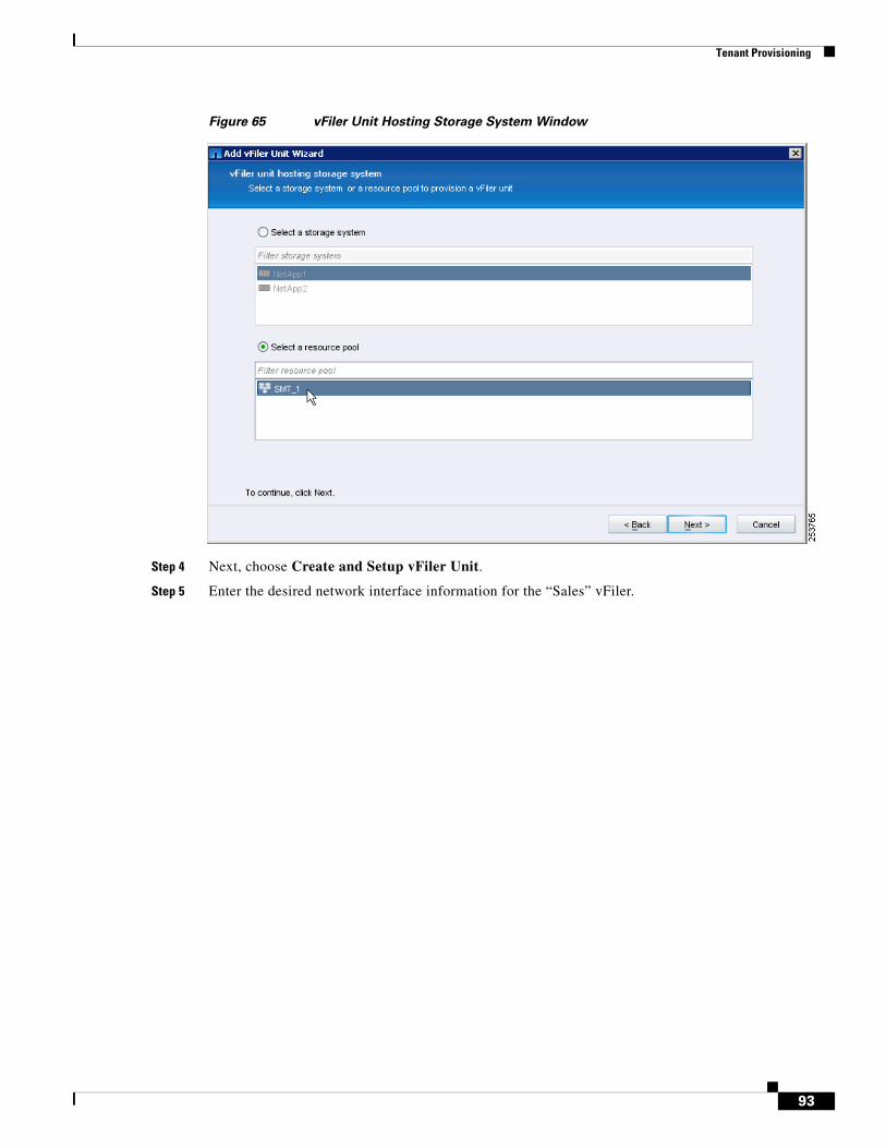
Tenant Provisioning
Figure 65 vFiler Unit Hosting Storage System Window
Step 4 Next, choose Create and Setup vFiler Unit.
Step 5 Enter the desired network interface information for the “Sales” vFiler.
93
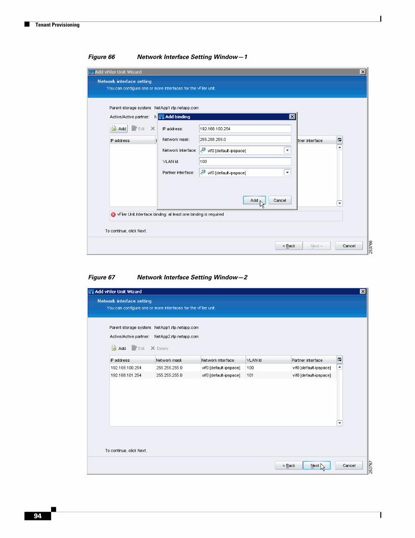
Tenant Provisioning
Figure 66 Network Interface Setting Window—1
Figure 67 Network Interface Setting Window—2
94
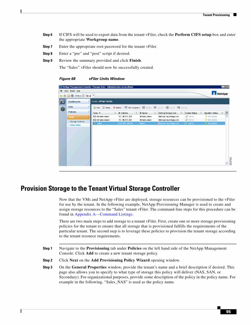
Tenant Provisioning
Step 6 If CIFS will be used to export data from the tenant vFiler, check the Perform CIFS setup box and enter the appropriate Workgroup name.
Step 7 Enter the appropriate root password for the tenant vFiler.
Step 8 Enter a “pre” and “post” script if desired.
Step 9 Review the summary provided and click Finish.
The “Sales” vFiler should now be successfully created.
Figure 68 vFiler Units Window
Provision Storage to the Tenant Virtual Storage ControllerNow that the VMs and NetApp vFiler are deployed, storage resources can be provisioned to the vFiler for use by the tenant. In the following example, NetApp Provisioning Manager is used to create and assign storage resources to the “Sales” tenant vFiler. The command-line steps for this procedure can be found in Appendix A—Command Listings.
There are two main steps to add storage to a tenant vFiler. First, create one or more storage provisioning policies for the tenant to ensure that all storage that is provisioned fulfills the requirements of the particular tenant. The second step is to leverage these policies to provision the tenant storage according to the tenant resource requirements.
Step 1 Navigate to the Provisioning tab under Policies on the left hand side of the NetApp Management Console. Click Add to create a new tenant storage policy.
Step 2 Click Next on the Add Provisioning Policy Wizard opening window.
Step 3 On the General Properties window, provide the tenant’s name and a brief description if desired. This page also allows you to specify to what type of storage this policy will deliver (NAS, SAN, or Secondary). For organizational purposes, provide some description of the policy in the policy name. For example in the following, “Sales_NAS” is used as the policy name.
95
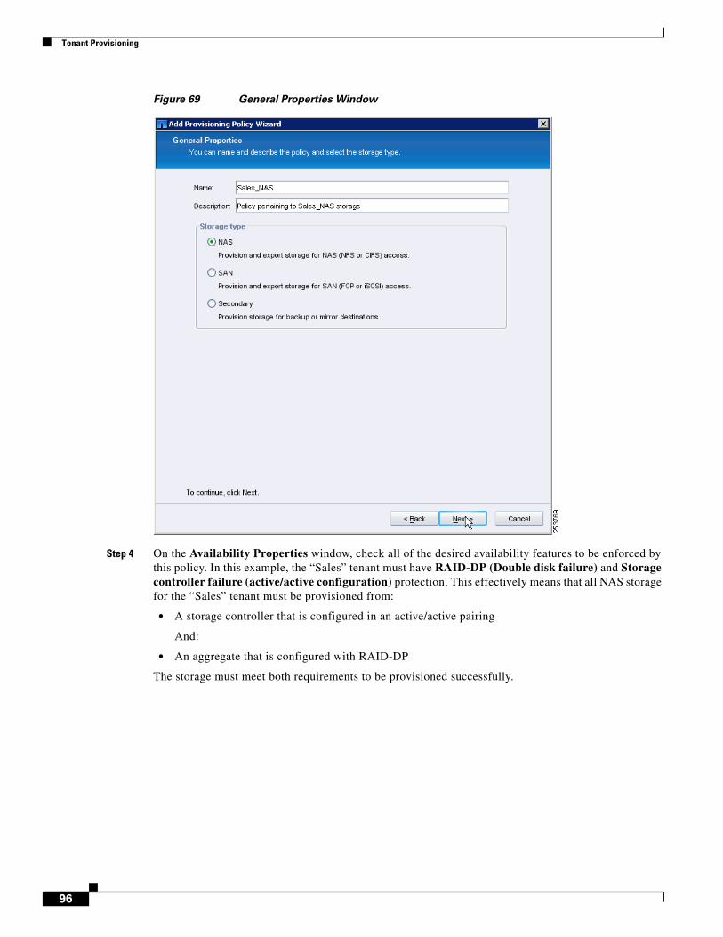
Tenant Provisioning
Figure 69 General Properties Window
Step 4 On the Availability Properties window, check all of the desired availability features to be enforced by this policy. In this example, the “Sales” tenant must have RAID-DP (Double disk failure) and Storage controller failure (active/active configuration) protection. This effectively means that all NAS storage for the “Sales” tenant must be provisioned from:
• A storage controller that is configured in an active/active pairing
And:
• An aggregate that is configured with RAID-DP
The storage must meet both requirements to be provisioned successfully.
96
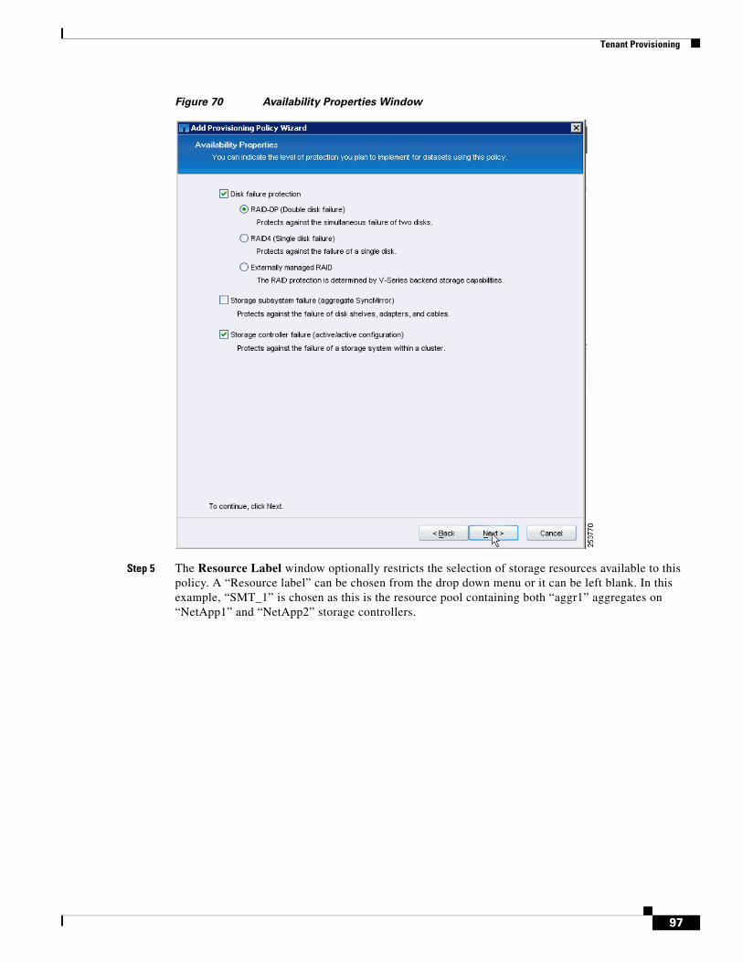
Tenant Provisioning
Figure 70 Availability Properties Window
Step 5 The Resource Label window optionally restricts the selection of storage resources available to this policy. A “Resource label” can be chosen from the drop down menu or it can be left blank. In this example, “SMT_1” is chosen as this is the resource pool containing both “aggr1” aggregates on “NetApp1” and “NetApp2” storage controllers.
97
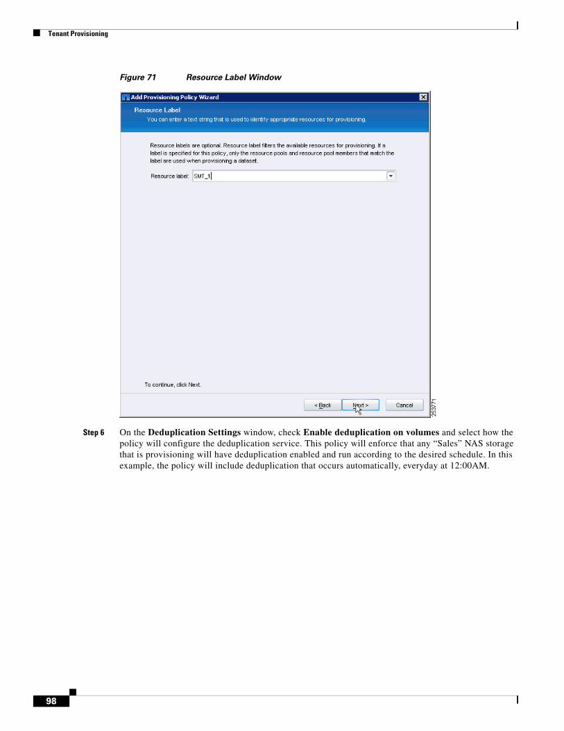
Tenant Provisioning
Figure 71 Resource Label Window
Step 6 On the Deduplication Settings window, check Enable deduplication on volumes and select how the policy will configure the deduplication service. This policy will enforce that any “Sales” NAS storage that is provisioning will have deduplication enabled and run according to the desired schedule. In this example, the policy will include deduplication that occurs automatically, everyday at 12:00AM.
98
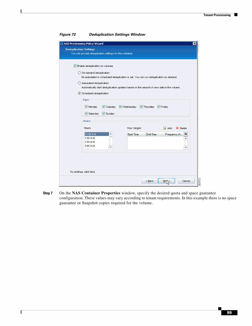
Tenant Provisioning
Figure 72 Deduplication Settings Window
Step 7 On the NAS Container Properties window, specify the desired quota and space guarantee configuration. These values may vary according to tenant requirements. In this example there is no space guarantee or Snapshot copies required for the volume.
99
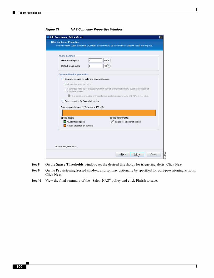
Tenant Provisioning
Figure 73 NAS Container Properties Window
Step 8 On the Space Thresholds window, set the desired thresholds for triggering alerts. Click Next.
Step 9 On the Provisioning Script window, a script may optionally be specified for post-provisioning actions. Click Next.
Step 10 View the final summary of the “Sales_NAS” policy and click Finish to save.
100
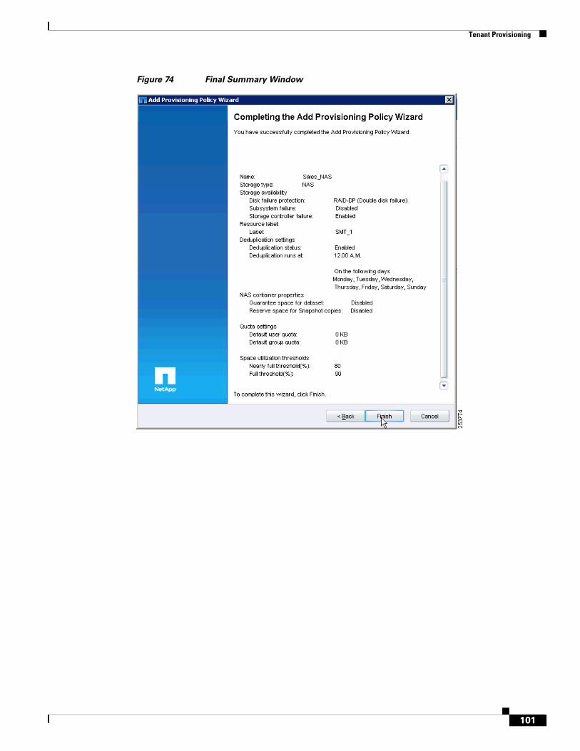
Tenant Provisioning
Figure 74 Final Summary Window
101
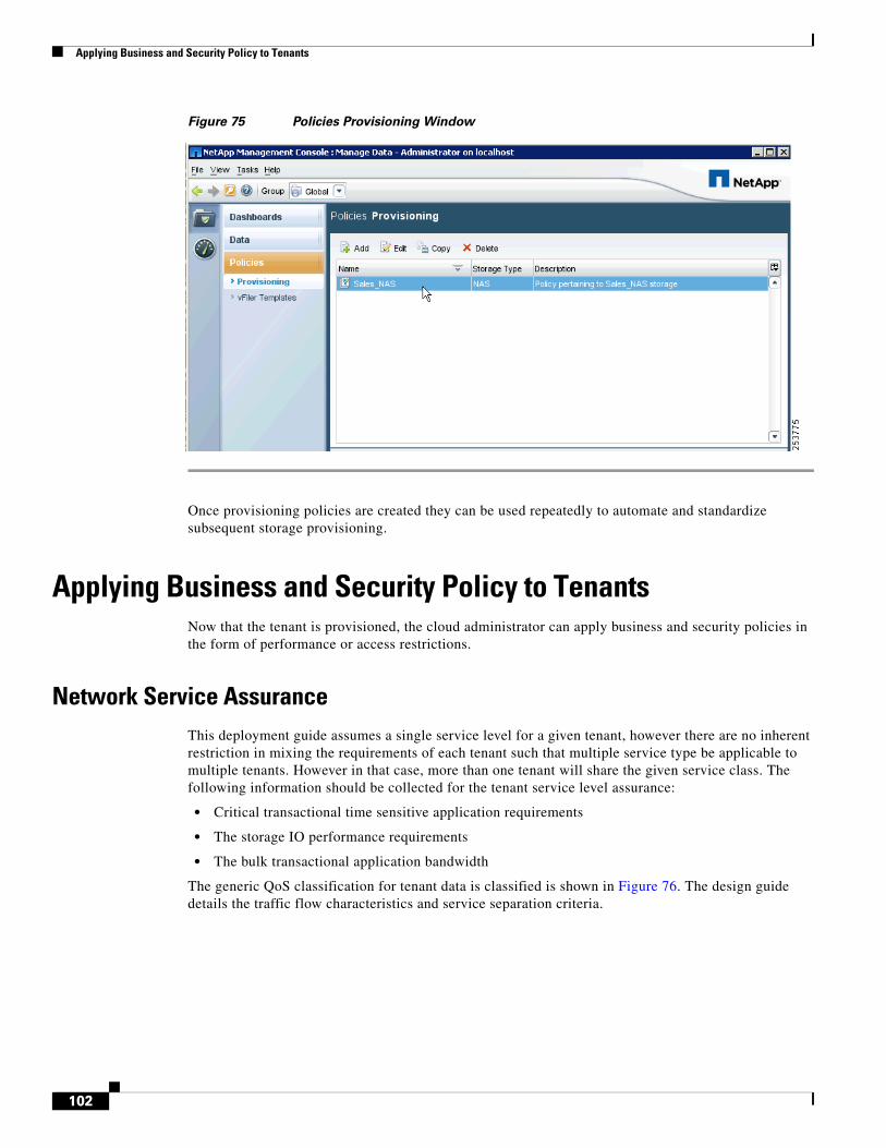
Applying Business and Security Policy to Tenants
Figure 75 Policies Provisioning Window
Once provisioning policies are created they can be used repeatedly to automate and standardize subsequent storage provisioning.
Applying Business and Security Policy to TenantsNow that the tenant is provisioned, the cloud administrator can apply business and security policies in the form of performance or access restrictions.
Network Service AssuranceThis deployment guide assumes a single service level for a given tenant, however there are no inherent restriction in mixing the requirements of each tenant such that multiple service type be applicable to multiple tenants. However in that case, more than one tenant will share the given service class. The following information should be collected for the tenant service level assurance:
• Critical transactional time sensitive application requirements
• The storage IO performance requirements
• The bulk transactional application bandwidth
The generic QoS classification for tenant data is classified is shown in Figure 76. The design guide details the traffic flow characteristics and service separation criteria.
102
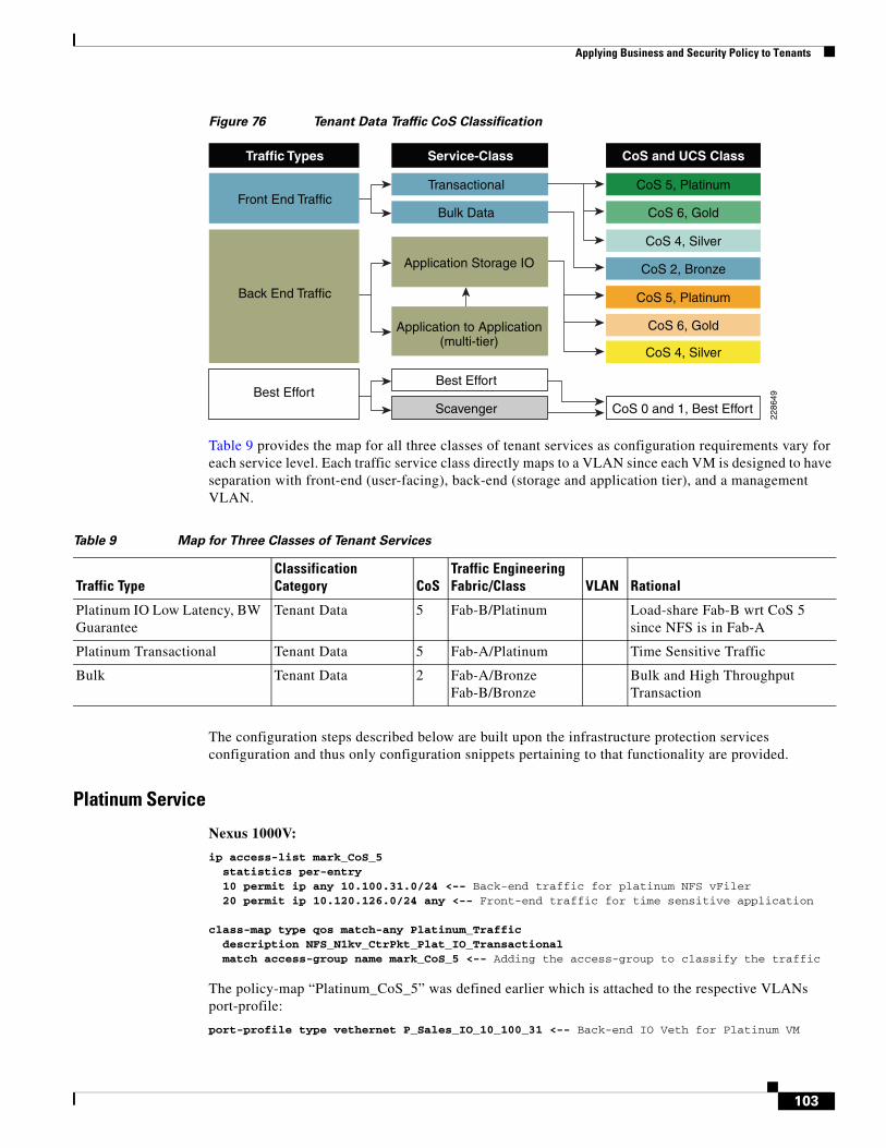
Applying Business and Security Policy to Tenants
Figure 76 Tenant Data Traffic CoS Classification
Table 9 provides the map for all three classes of tenant services as configuration requirements vary for each service level. Each traffic service class directly maps to a VLAN since each VM is designed to have separation with front-end (user-facing), back-end (storage and application tier), and a management VLAN.
The configuration steps described below are built upon the infrastructure protection services configuration and thus only configuration snippets pertaining to that functionality are provided.
Platinum Service
Nexus 1000V:
ip access-list mark_CoS_5 statistics per-entry 10 permit ip any 10.100.31.0/24 <-- Back-end traffic for platinum NFS vFiler 20 permit ip 10.120.126.0/24 any <-- Front-end traffic for time sensitive application class-map type qos match-any Platinum_Traffic description NFS_N1kv_CtrPkt_Plat_IO_Transactional match access-group name mark_CoS_5 <-- Adding the access-group to classify the traffic
The policy-map “Platinum_CoS_5” was defined earlier which is attached to the respective VLANs port-profile:
port-profile type vethernet P_Sales_IO_10_100_31 <-- Back-end IO Veth for Platinum VM
Back End Traffic
Traffic Types
Bulk Data
Application Storage IO
Front End Traffic
Application to Application(multi-tier)
Best EffortBest Effort
Scavenger
Service-Class
CoS 6, Gold
CoS 2, Bronze
CoS 6, Gold
CoS 4, Silver
CoS and UCS Class
CoS 5, Platinum
CoS 5, Platinum
CoS 4, Silver
CoS 0 and 1, Best Effort
Transactional
2286
49
Table 9 Map for Three Classes of Tenant Services
Traffic TypeClassification Category CoS
Traffic Engineering Fabric/Class VLAN Rational
Platinum IO Low Latency, BW Guarantee
Tenant Data 5 Fab-B/Platinum Load-share Fab-B wrt CoS 5 since NFS is in Fab-A
Platinum Transactional Tenant Data 5 Fab-A/Platinum Time Sensitive Traffic
Bulk Tenant Data 2 Fab-A/Bronze Fab-B/Bronze
Bulk and High Throughput Transaction
103
Applying Business and Security Policy to Tenants
switchport access vlan 301 service-policy type qos input Platinum_CoS_5 <-- Attaching the policy-map pinning id 1 <-- Fabric B no shutdown state enabled port-profile type vethernet P_Sales_Transactional_10_120_126 <-- Front-end transactional switchport access vlan 126 service-policy type qos input Platinum_CoS_5 pinning id 0 <-- Fabric A state enabled
Nexus 5000:
Adding tenant specific classification and queuing to already defined policy-maps and class-maps:
Caution This design utilizes the vPC technology to enable loop-less design. The vPC configuration mandates that both Nexus 5000s be configured with consistent set of global configuration. It is recommended to enable QoS polices at the systems level before the vPC is enabled. If the QoS configuration is applied after the vPC configuration, both Nexus 5000s must enable the QoS simultaneously. Failure to follow this practice would disable all the VLANs belonging to vPC topology.
ip access-list classify_CoS_5 20 permit ip 10.100.31.254/32 any <-- Adding Platinum vFiler for traffic from NetApp
The rest of the configuration is already defined under infrastructure protection services.
Gold Service
Nexus 1000V:
Adding tenant specific classification, the rest of the configuration is already defined under infrastructure protection services:
ip access-list classify_CoS_6 20 permit ip 10.100.21.254/32 any <-- Adding Gold vFiler for traffic from NetApp 30 permit ip 10.120.125.0/24 any <-- Front-end traffic with Gold service
The policy-map “Gold_CoS_6” was defined earlier which is attached to the respective VLANs port-profile:
port-profile type vethernet G_MKT_IO_10_100_21 <-- Back-end IO Veth for Gold VM switchport access vlan 201 service-policy type qos input Gold_CoS_6 pinning id 0 <-- Fabric A port-profile type vethernet G_Mkt_Transactional_10_120_125 <-- Front-end Transactional switchport access vlan 125
Table 10 Gold Service—Front-End Gold Transactional, Back-End IO Med Latency, No Drop
Traffic TypeClassification Category CoS
Traffic Engineering Fabric/Class VLAN Rational
Gold IO Med Latency, No Drop
Tenant Data 6 Fab-A/Gold no-drop to buffer
Load-share Fab-A, since platinum-IO is on Fab-A
Gold Transactional Tenant Data 6 Fab-B/Gold Time Sensitive Traffic
104
Applying Business and Security Policy to Tenants
service-policy type qos input Gold_CoS_6 pinning id 1 <-- Fabric B
Nexus 5000:
Caution This design utilizes the vPC technology to enable loop-less design. The vPC configuration mandates that both Nexus 5000s be configured with consistent set of global configuration. It is recommended to enable QoS polices at the systems level before the vPC is enabled. If the QoS configuration is applied after the vPC configuration, both Nexus 5000s must enable the QoS simultaneously. Failure to follow this practice would disable all the VLANs belonging to vPC topology.
Adding tenant specific classification and queuing to already defined policy-maps and class-maps:
Match and associate the class-map for NetApp gold vFiler storage traffic coming into Nexus 5000 to mark with the proper CoS configuration.
ip access-list classify_CoS_6 <-- Defining Gold vFiler for traffic from NetApp 10 permit ip 10.100.21.254/32 any <-- Gold vFiler source class-map type qos Gold_Traffic match access-group name classify_CoS_6
An additional update is required to global classifier since the “Gold_Traffic” was not defined in the “Global_Classify_NFS_Application” policy-map.
policy-map type qos Global_Classify_NFS_Application class Gold_Traffic set qos-group 3
The configuration below matches the CoS for NetApp traffic coming from storage which was classified with the above qos-group. The class-map and policy-may of type “network-qos” is required for changing the QoS parameter.
class-map type network-qos Gold_Traffic_NQ match qos-group 3
The policy-map below uses the above class-map to set the CoS value for gold vFiler NFS traffic.
policy-map type network-qos Netapp_Qos class type network-qos Gold_Traffic_NQ set cos 6 queue-limit 30000 bytes
The rest of the configuration is already defined under infrastructure protection services.
Silver Service
Table 11 Silver Service
Traffic TypeClassification Category CoS
Traffic Engineering Fabric/Class VLAN Rational
Silver Transactional Tenant Data 4 Fab-A/Silver Competing with vMotion only when vMotion occurs
Silver IO High Latency, Drop/Retransmit
Tenant Data 4 Fab-B/Silver Fab-A has vMotion
105
Applying Business and Security Policy to Tenants
Nexus 1000V:
Add tenant specific classification, the rest of the configuration is already defined under infrastructure protection services.
ip access-list mark_CoS_4 20 permit ip any 10.100.41.0/24 <-- Adding Silver vFiler for traffic from NetApp 30 permit ip 10.120.127.0/24 any <-- Front-end traffic with Gold service class-map type qos match-all Silver_Traffic match access-group name mark_CoS_4
The policy-map “Silver_CoS_6” (defined earlier) is attached to the respective VLAN’s port-profile:
port-profile type vethernet S_HR_IO_10_100_41 <-- Back-end IO Veth for Gold VM switchport access vlan 401 service-policy type qos input Silver_CoS_4 pinning id 0 <-- Fabric A port-profile type vethernet S_HR_Transactional_10_120_127 Ð Front-end Transactional switchport access vlan 127 service-policy type qos input Silver_CoS_4 pinning id 1 <-- Fabric B
Additionally, the rate-limit is applied for silver services since this service is considered a “fixed-rate” service.
policy-map type qos Silver_CoS_4 class Silver_Traffic set cos 4 police cir 5 mbps bc 200 ms conform transmit violate set dscp dscp table pir-markdown-map
Note that in the policy-map above, a single class-map, defined earlier, has both a transactional and storage (IO) classification, which implies all traffic for the class-map is subject to policing. If distinct policing is required then one has to define a distinct class-map for each type of traffic. The example above illustrates the third and final service level differentiation sought in SMT deployment.
Nexus 5000:
Caution This design utilizes the vPC technology to enable loop-less design. The vPC configuration mandates that both Nexus 5000s be configured with consistent set of global configuration. It is recommended to enable QoS polices at the systems level before the vPC is enabled. If the QoS configuration is applied after the vPC configuration, both Nexus 5000s must enable the QoS simultaneously. Failure to follow this practice would disable all the VLANs belonging to vPC topology.
Adding tenant specific classification and queuing to already defined policy-maps and class-maps:
Matching and associating a class-map for NetApp silver vFiler storage traffic coming into Nexus 5000 to mark with the proper CoS configuration.
ip access-list classify_CoS_4 <-- Defining Silver vFiler for traffic from NetApp 10 permit ip 10.100.41.254/32 any <-- Silver vFiler source class-map type qos Silver_Traffic match access-group name classify_CoS_4
The additional update is required to the global classifier since the “Silver_Traffic” is not defined in “Global_Classify_NFS_Application” policy-map.
policy-map type qos Global_Classify_NFS_Application class Silver_Traffic
106
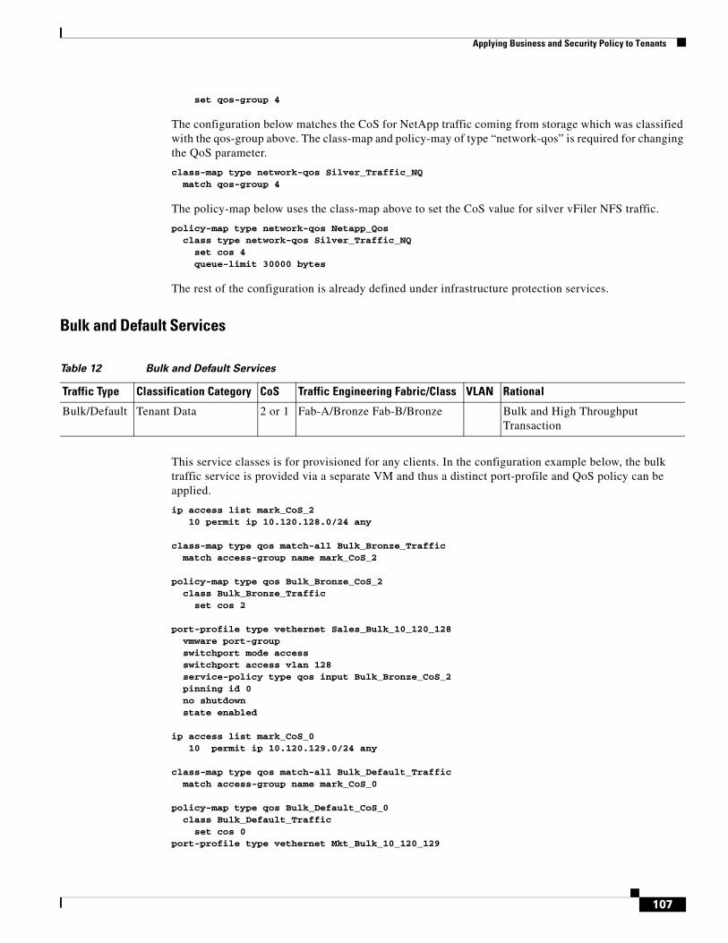
Applying Business and Security Policy to Tenants
set qos-group 4
The configuration below matches the CoS for NetApp traffic coming from storage which was classified with the qos-group above. The class-map and policy-may of type “network-qos” is required for changing the QoS parameter.
class-map type network-qos Silver_Traffic_NQ match qos-group 4
The policy-map below uses the class-map above to set the CoS value for silver vFiler NFS traffic.
policy-map type network-qos Netapp_Qos class type network-qos Silver_Traffic_NQ set cos 4 queue-limit 30000 bytes
The rest of the configuration is already defined under infrastructure protection services.
Bulk and Default Services
This service classes is for provisioned for any clients. In the configuration example below, the bulk traffic service is provided via a separate VM and thus a distinct port-profile and QoS policy can be applied.
ip access list mark_CoS_2 10 permit ip 10.120.128.0/24 any class-map type qos match-all Bulk_Bronze_Traffic match access-group name mark_CoS_2 policy-map type qos Bulk_Bronze_CoS_2 class Bulk_Bronze_Traffic set cos 2 port-profile type vethernet Sales_Bulk_10_120_128 vmware port-group switchport mode access switchport access vlan 128 service-policy type qos input Bulk_Bronze_CoS_2 pinning id 0 no shutdown state enabled ip access list mark_CoS_0 10 permit ip 10.120.129.0/24 any class-map type qos match-all Bulk_Default_Traffic match access-group name mark_CoS_0 policy-map type qos Bulk_Default_CoS_0 class Bulk_Default_Traffic set cos 0 port-profile type vethernet Mkt_Bulk_10_120_129
Table 12 Bulk and Default Services
Traffic Type Classification Category CoS Traffic Engineering Fabric/Class VLAN Rational
Bulk/Default Tenant Data 2 or 1 Fab-A/Bronze Fab-B/Bronze Bulk and High Throughput Transaction
107
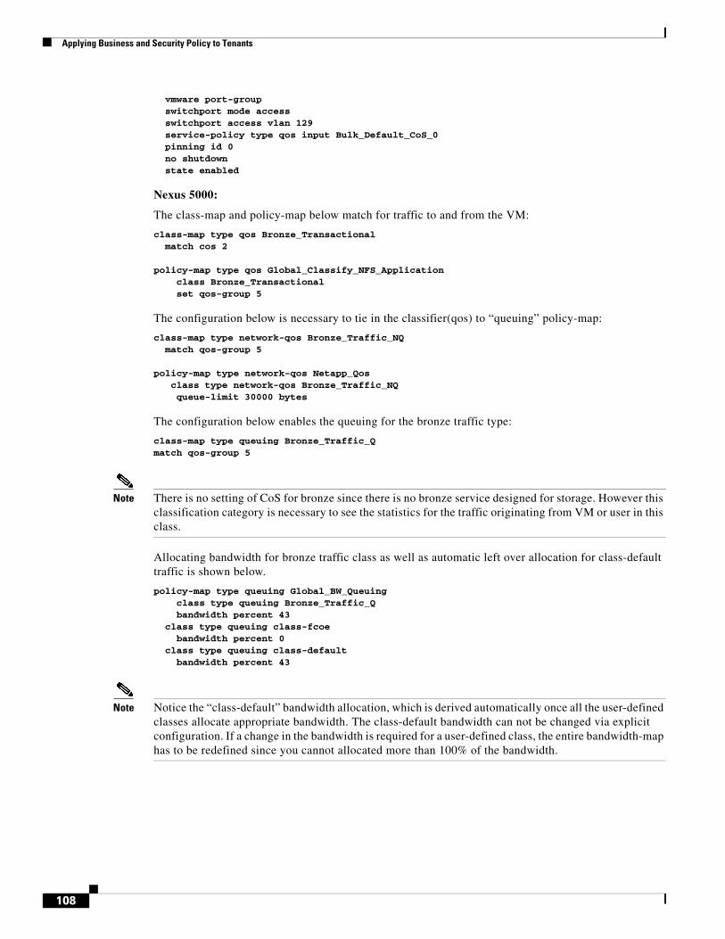
Applying Business and Security Policy to Tenants
vmware port-group switchport mode access switchport access vlan 129 service-policy type qos input Bulk_Default_CoS_0 pinning id 0 no shutdown state enabled
Nexus 5000:
The class-map and policy-map below match for traffic to and from the VM:
class-map type qos Bronze_Transactional match cos 2 policy-map type qos Global_Classify_NFS_Application class Bronze_Transactional set qos-group 5
The configuration below is necessary to tie in the classifier(qos) to “queuing” policy-map:
class-map type network-qos Bronze_Traffic_NQ match qos-group 5 policy-map type network-qos Netapp_Qos class type network-qos Bronze_Traffic_NQ queue-limit 30000 bytes
The configuration below enables the queuing for the bronze traffic type:
class-map type queuing Bronze_Traffic_Q match qos-group 5
Note There is no setting of CoS for bronze since there is no bronze service designed for storage. However this classification category is necessary to see the statistics for the traffic originating from VM or user in this class.
Allocating bandwidth for bronze traffic class as well as automatic left over allocation for class-default traffic is shown below.
policy-map type queuing Global_BW_Queuing class type queuing Bronze_Traffic_Q bandwidth percent 43 class type queuing class-fcoe bandwidth percent 0 class type queuing class-default bandwidth percent 43
Note Notice the “class-default” bandwidth allocation, which is derived automatically once all the user-defined classes allocate appropriate bandwidth. The class-default bandwidth can not be changed via explicit configuration. If a change in the bandwidth is required for a user-defined class, the entire bandwidth-map has to be redefined since you cannot allocated more than 100% of the bandwidth.
108
Applying Business and Security Policy to Tenants
Managing Contention for Storage Resources with FlexShareFlexShare provides a method for prioritizing controller resource contention between individual storage volumes. Volumes are queued based on their configured priority level as storage resources become constrained. If there is no contention of resources, no queuing takes place and all volumes perform at equal priorities. When initially started, FlexShare places all volumes in the “default” priority queue in which all volumes are given equal priority should contention occur. When assigning priority levels, ensure all volumes have a configured priority level. Leaving volumes in the “default” priority queue could result in an unexpected priority order because all volumes with a “default” configuration share the same resources allocated to the default queue. No license is required for FlexShare.
To configure FlexShare, perform the following steps:
Step 1 Enable FlexShare priority queueing.
NetApp1> priority on Priority scheduler is running.
Step 2 Configure the appropriate priority level (VeryHigh, High, Medium, Low or VeryLow) on a per volume basis.
Command syntax example: priority set volume level=<priority_level> <volume_name>
NetApp1> priority set volume level=VeryHigh Sales_app1 NetApp1> priority show volume Sales_app1 Volume Priority Relative Sys Priority Service Priority (vs User) Sales_app1 on VeryHigh Medium
Governing Compute Resources Using VMware Resource PoolsThe following resource pool settings provide governance for compute (CPU and memory) resources for each and every tenant in the environment:
• Reservation (set aside a specified amount of CPU and memory resources)
• Limit (maximum amount of CPU and memory resources consumable by the tenant)
• Shares (dictates preferential treatment to tenants with higher share value under resource contention)
• Expandable Reservation (if enabled, tenant resource pool can utilize additional available CPU and memory resource from parent resource pool)
Ensure each tenant resource pool has the above attributes set based on the tenant’s SLA. To configure the settings, right click on the tenant resource pool and select edit to specify shares, reservations, limits, and expandable reservation for both CPU and memory resources:
109
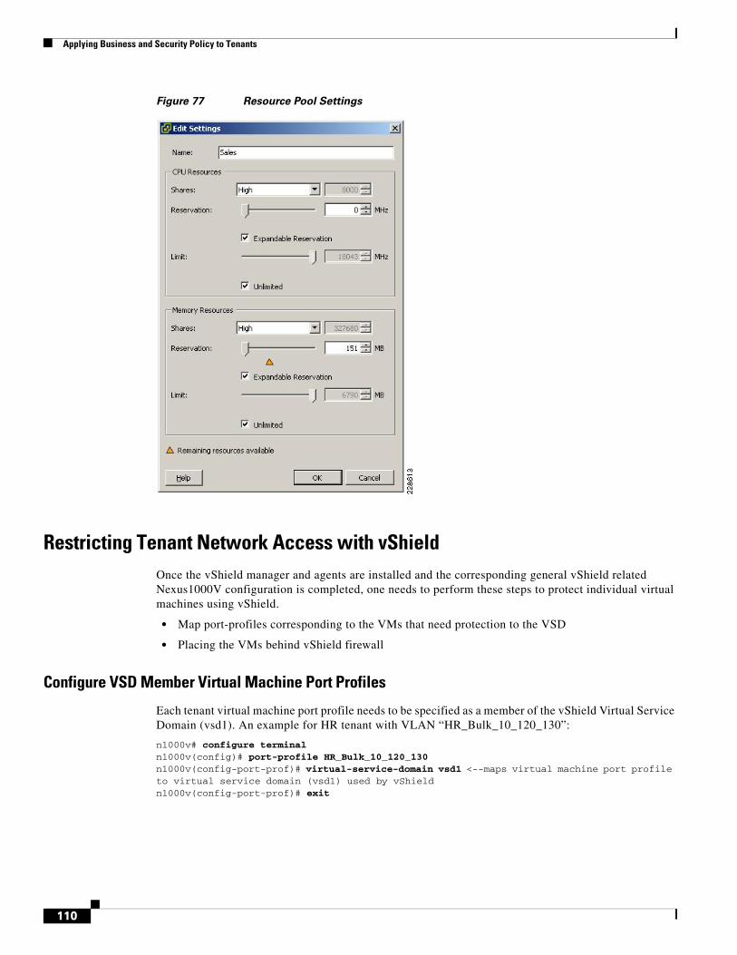
Applying Business and Security Policy to Tenants
Figure 77 Resource Pool Settings
Restricting Tenant Network Access with vShield Once the vShield manager and agents are installed and the corresponding general vShield related Nexus1000V configuration is completed, one needs to perform these steps to protect individual virtual machines using vShield.
• Map port-profiles corresponding to the VMs that need protection to the VSD
• Placing the VMs behind vShield firewall
Configure VSD Member Virtual Machine Port Profiles
Each tenant virtual machine port profile needs to be specified as a member of the vShield Virtual Service Domain (vsd1). An example for HR tenant with VLAN “HR_Bulk_10_120_130”:
n1000v# configure terminal n1000v(config)# port-profile HR_Bulk_10_120_130 n1000v(config-port-prof)# virtual-service-domain vsd1 <--maps virtual machine port profile to virtual service domain (vsd1) used by vShield n1000v(config-port-prof)# exit
110
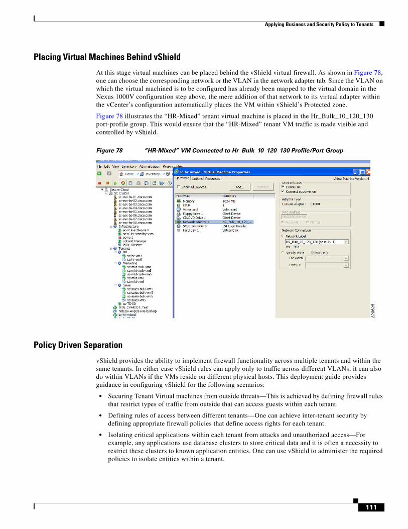
Applying Business and Security Policy to Tenants
Placing Virtual Machines Behind vShield
At this stage virtual machines can be placed behind the vShield virtual firewall. As shown in Figure 78, one can choose the corresponding network or the VLAN in the network adapter tab. Since the VLAN on which the virtual machined is to be configured has already been mapped to the virtual domain in the Nexus 1000V configuration step above, the mere addition of that network to its virtual adapter within the vCenter’s configuration automatically places the VM within vShield’s Protected zone.
Figure 78 illustrates the “HR-Mixed” tenant virtual machine is placed in the Hr_Bulk_10_120_130 port-profile group. This would ensure that the “HR-Mixed” tenant VM traffic is made visible and controlled by vShield.
Figure 78 “HR-Mixed” VM Connected to Hr_Bulk_10_120_130 Profile/Port Group
Policy Driven Separation
vShield provides the ability to implement firewall functionality across multiple tenants and within the same tenants. In either case vShield rules can apply only to traffic across different VLANs; it can also do within VLANs if the VMs reside on different physical hosts. This deployment guide provides guidance in configuring vShield for the following scenarios:
• Securing Tenant Virtual machines from outside threats—This is achieved by defining firewall rules that restrict types of traffic from outside that can access guests within each tenant.
• Defining rules of access between different tenants—One can achieve inter-tenant security by defining appropriate firewall policies that define access rights for each tenant.
• Isolating critical applications within each tenant from attacks and unauthorized access—For example, any applications use database clusters to store critical data and it is often a necessity to restrict these clusters to known application entities. One can use vShield to administer the required policies to isolate entities within a tenant.
111
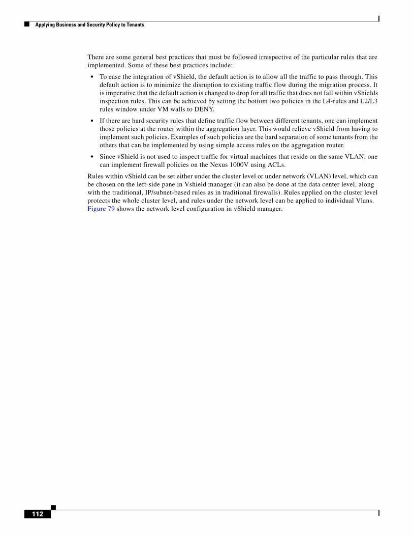
Applying Business and Security Policy to Tenants
There are some general best practices that must be followed irrespective of the particular rules that are implemented. Some of these best practices include:
• To ease the integration of vShield, the default action is to allow all the traffic to pass through. This default action is to minimize the disruption to existing traffic flow during the migration process. It is imperative that the default action is changed to drop for all traffic that does not fall within vShields inspection rules. This can be achieved by setting the bottom two policies in the L4-rules and L2/L3 rules window under VM walls to DENY.
• If there are hard security rules that define traffic flow between different tenants, one can implement those policies at the router within the aggregation layer. This would relieve vShield from having to implement such policies. Examples of such policies are the hard separation of some tenants from the others that can be implemented by using simple access rules on the aggregation router.
• Since vShield is not used to inspect traffic for virtual machines that reside on the same VLAN, one can implement firewall policies on the Nexus 1000V using ACLs.
Rules within vShield can be set either under the cluster level or under network (VLAN) level, which can be chosen on the left-side pane in Vshield manager (it can also be done at the data center level, along with the traditional, IP/subnet-based rules as in traditional firewalls). Rules applied on the cluster level protects the whole cluster level, and rules under the network level can be applied to individual Vlans. Figure 79 shows the network level configuration in vShield manager.
112
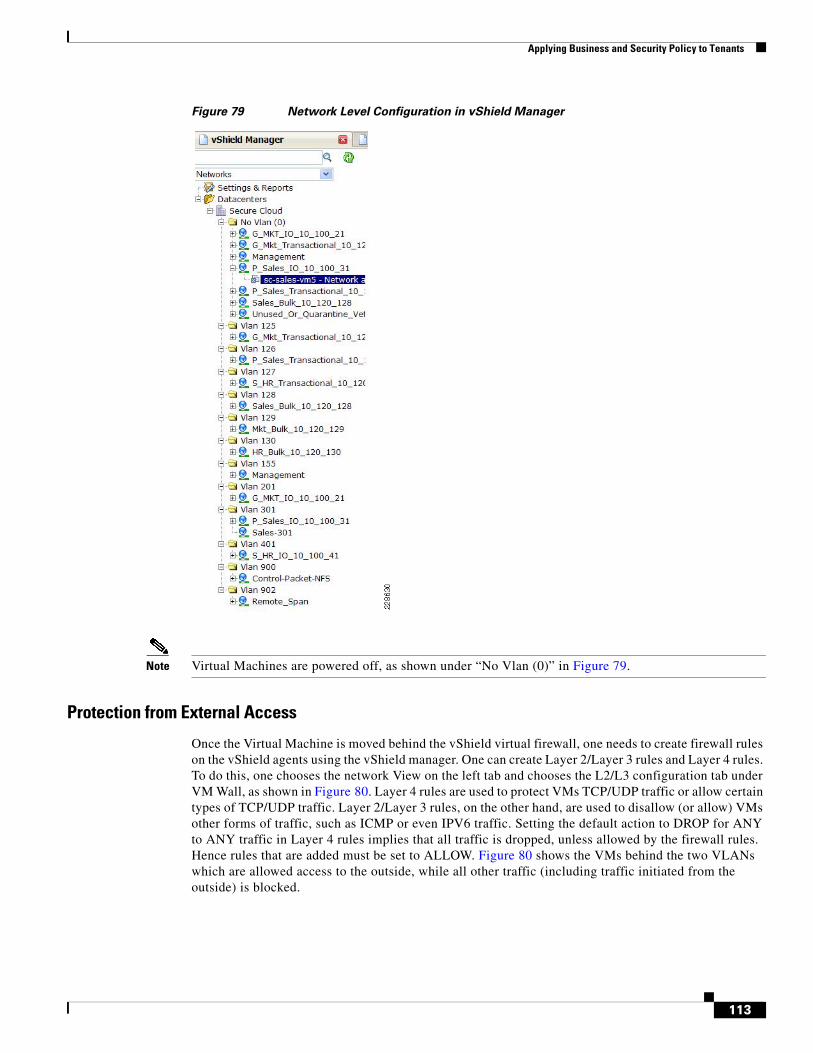
Applying Business and Security Policy to Tenants
Figure 79 Network Level Configuration in vShield Manager
Note Virtual Machines are powered off, as shown under “No Vlan (0)” in Figure 79.
Protection from External Access
Once the Virtual Machine is moved behind the vShield virtual firewall, one needs to create firewall rules on the vShield agents using the vShield manager. One can create Layer 2/Layer 3 rules and Layer 4 rules. To do this, one chooses the network View on the left tab and chooses the L2/L3 configuration tab under VM Wall, as shown in Figure 80. Layer 4 rules are used to protect VMs TCP/UDP traffic or allow certain types of TCP/UDP traffic. Layer 2/Layer 3 rules, on the other hand, are used to disallow (or allow) VMs other forms of traffic, such as ICMP or even IPV6 traffic. Setting the default action to DROP for ANY to ANY traffic in Layer 4 rules implies that all traffic is dropped, unless allowed by the firewall rules. Hence rules that are added must be set to ALLOW. Figure 80 shows the VMs behind the two VLANs which are allowed access to the outside, while all other traffic (including traffic initiated from the outside) is blocked.
113
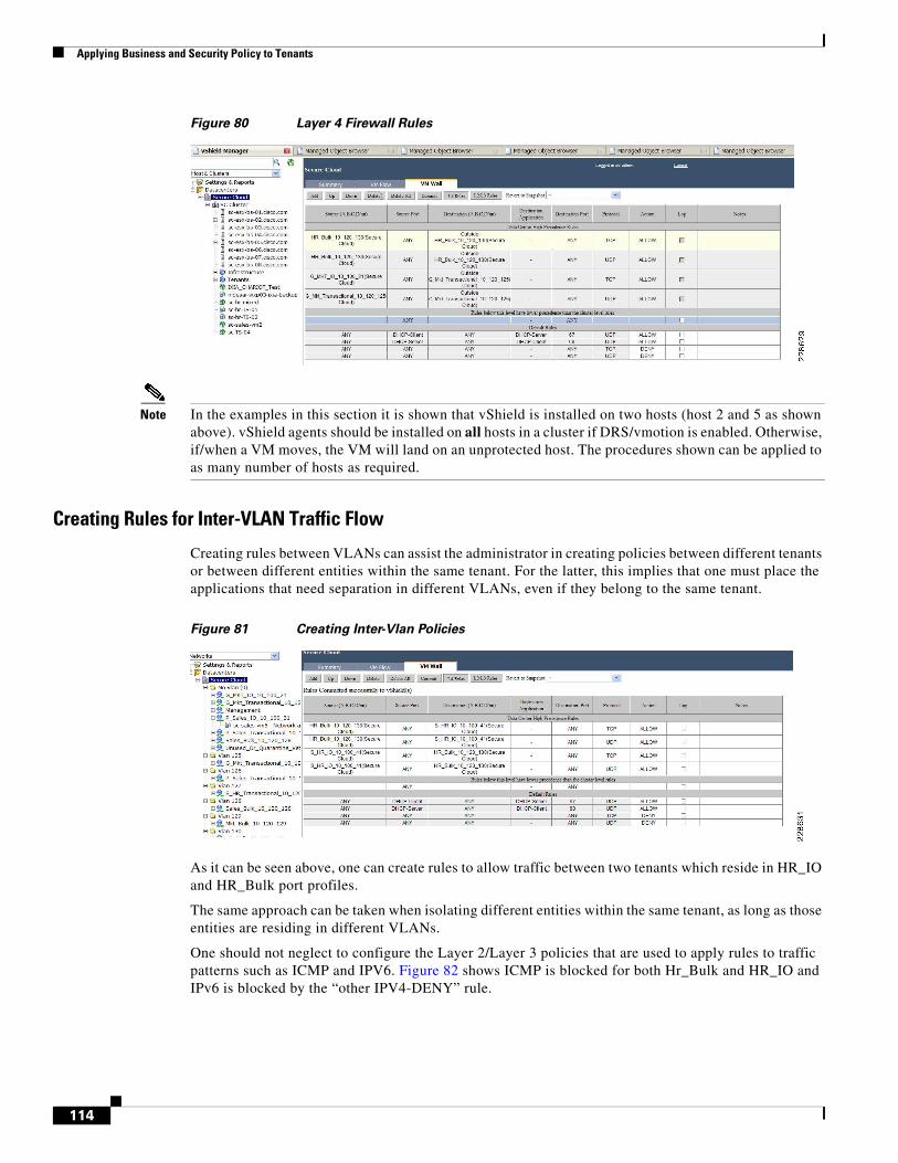
Applying Business and Security Policy to Tenants
Figure 80 Layer 4 Firewall Rules
Note In the examples in this section it is shown that vShield is installed on two hosts (host 2 and 5 as shown above). vShield agents should be installed on all hosts in a cluster if DRS/vmotion is enabled. Otherwise, if/when a VM moves, the VM will land on an unprotected host. The procedures shown can be applied to as many number of hosts as required.
Creating Rules for Inter-VLAN Traffic Flow
Creating rules between VLANs can assist the administrator in creating policies between different tenants or between different entities within the same tenant. For the latter, this implies that one must place the applications that need separation in different VLANs, even if they belong to the same tenant.
Figure 81 Creating Inter-Vlan Policies
As it can be seen above, one can create rules to allow traffic between two tenants which reside in HR_IO and HR_Bulk port profiles.
The same approach can be taken when isolating different entities within the same tenant, as long as those entities are residing in different VLANs.
One should not neglect to configure the Layer 2/Layer 3 policies that are used to apply rules to traffic patterns such as ICMP and IPV6. Figure 82 shows ICMP is blocked for both Hr_Bulk and HR_IO and IPv6 is blocked by the “other IPV4-DENY” rule.
114
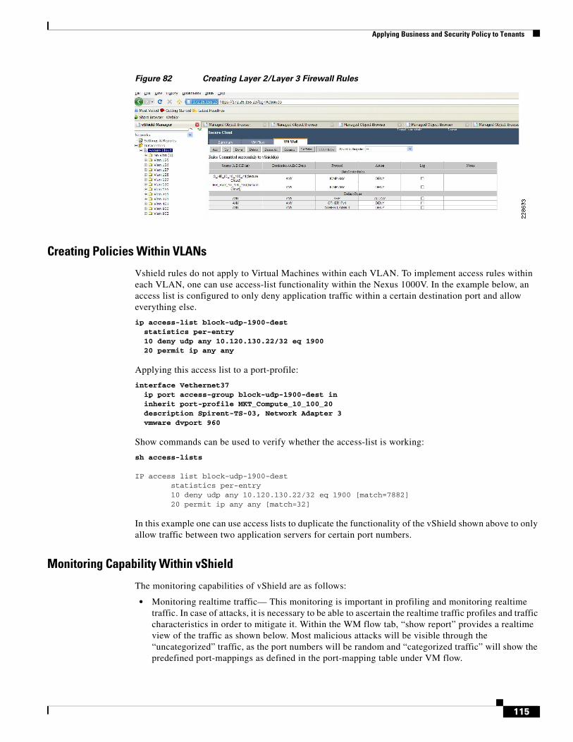
Applying Business and Security Policy to Tenants
Figure 82 Creating Layer 2/Layer 3 Firewall Rules
Creating Policies Within VLANs
Vshield rules do not apply to Virtual Machines within each VLAN. To implement access rules within each VLAN, one can use access-list functionality within the Nexus 1000V. In the example below, an access list is configured to only deny application traffic within a certain destination port and allow everything else.
ip access-list block-udp-1900-dest statistics per-entry 10 deny udp any 10.120.130.22/32 eq 1900 20 permit ip any any
Applying this access list to a port-profile:
interface Vethernet37 ip port access-group block-udp-1900-dest in inherit port-profile MKT_Compute_10_100_20 description Spirent-TS-03, Network Adapter 3 vmware dvport 960
Show commands can be used to verify whether the access-list is working:
sh access-lists IP access list block-udp-1900-dest statistics per-entry 10 deny udp any 10.120.130.22/32 eq 1900 [match=7882] 20 permit ip any any [match=32]
In this example one can use access lists to duplicate the functionality of the vShield shown above to only allow traffic between two application servers for certain port numbers.
Monitoring Capability Within vShield
The monitoring capabilities of vShield are as follows:
• Monitoring realtime traffic— This monitoring is important in profiling and monitoring realtime traffic. In case of attacks, it is necessary to be able to ascertain the realtime traffic profiles and traffic characteristics in order to mitigate it. Within the WM flow tab, “show report” provides a realtime view of the traffic as shown below. Most malicious attacks will be visible through the “uncategorized” traffic, as the port numbers will be random and “categorized traffic” will show the predefined port-mappings as defined in the port-mapping table under VM flow.
115
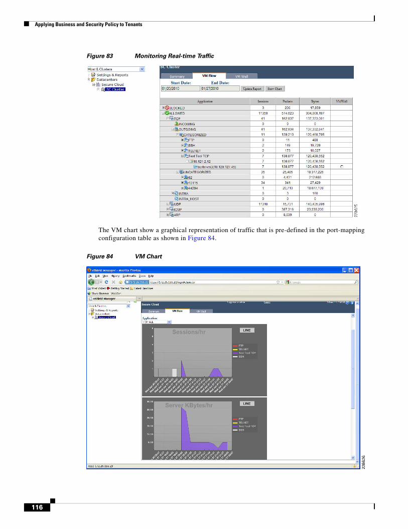
Applying Business and Security Policy to Tenants
Figure 83 Monitoring Real-time Traffic
The VM chart show a graphical representation of traffic that is pre-defined in the port-mapping configuration table as shown in Figure 84.
Figure 84 VM Chart
116
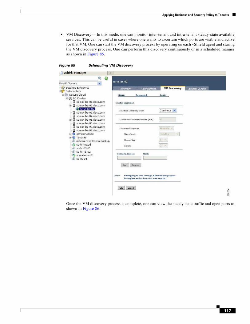
Applying Business and Security Policy to Tenants
• VM Discovery— In this mode, one can monitor inter-tenant and intra-tenant steady-state available services. This can be useful in cases where one wants to ascertain which ports are visible and active for that VM. One can start the VM discovery process by operating on each vShield agent and staring the VM discovery process. One can perform this discovery continuously or in a scheduled manner as shown in Figure 85.
Figure 85 Scheduling VM Discovery
Once the VM discovery process is complete, one can view the steady state traffic and open ports as shown in Figure 86.
117
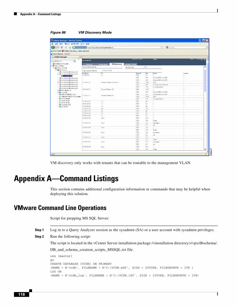
Appendix A—Command Listings
Figure 86 VM Discovery Mode
VM discovery only works with tenants that can be routable to the management VLAN.
Appendix A—Command ListingsThis section contains additional configuration information or commands that may be helpful when deploying this solution.
VMware Command Line OperationsScript for prepping MS SQL Server:
Step 1 Log in to a Query Analyzer session as the sysadmin (SA) or a user account with sysadmin privileges.
Step 2 Run the following script:
The script is located in the vCenter Server installation package /<installation directory>/vpx/dbschema/.
DB_and_schema_creation_scripts_MSSQL.txt file.
use [master] go CREATE DATABASE [VCDB] ON PRIMARY (NAME = N'vcdb', FILENAME = N'C:\VCDB.mdf', SIZE = 2000KB, FILEGROWTH = 10% ) LOG ON (NAME = N'vcdb_log', FILENAME = N'C:\VCDB.ldf', SIZE = 1000KB, FILEGROWTH = 10%)
118
Appendix A—Command Listings
COLLATE SQL_Latin1_General_CP1_CI_AS go use VCDB go sp_addlogin @loginame=[vpxuser], @passwd=N'vpxuser!0', @defdb='VCDB', @deflanguage='us_english' go ALTER LOGIN [vpxuser] WITH CHECK_POLICY = OFF go CREATE USER [vpxuser] for LOGIN [vpxuser] go sp_addrolemember @rolename = 'db_owner', @membername = 'vpxuser' go use MSDB go CREATE USER [vpxuser] for LOGIN [vpxuser] go sp_addrolemember @rolename = 'db_owner', @membername = 'vpxuser' go
NetApp Command Line OperationsThroughout the deployment guide some NetApp procedures are shown using GUI-based applications while others are shown leveraging the command line. All tasks shown using the command line in the body of the deployment guide are tasks that must be performed via CLI as there are no available GUI-based method at the time of writing. The following NetApp CLI procedures are provided in addition to the GUI-based procedures throughout the document should the administrator prefer CLI.
Create the Tenant vFiler(s) on the NetApp Storage (via Command Line)
The NetApp storage controllers have been configured as an HA cluster, so two controllers are available for use. Be sure to evenly distribute tenant vFilers across both NetApp storage controllers. In this example, NetApp1 is used.
Step 1 Create the vFiler root volume:
NetApp1> vol create Sales_root -s none aggr1 30m
Step 2 Create the VLAN interfaces:
NetApp1> vlan create vif0 100NetApp1> vlan add vif0 101
Step 3 Create the IPspace:
NetApp1> ipspace create Sales vif0-100, vif0-101
Step 4 Create the vFiler:
NetApp1> vFiler create Sales -s Sales -i 192.168.100.254 -i 192.168.101.254 /vol/Sales_root Setting up vFiler SalesConfigure vFiler IP address 192.168.100.254? [y]: (Press Enter)Interface to assign this address to {vif0-100 vif0-101}: vif0-100Netmask to use: [255.255.255.0]: (Press Enter) Configure vFiler IP address 192.168.101.254? [y]: (Press Enter)Interface to assign this address to {vif0-101}: vif0-101Netmask to use: [255.255.255.0]: (Press Enter)
119
Appendix A—Command Listings
Please enter the name or IP address of the administration host: (Press Enter) Do you want to run DNS resolver? [n]: (Press Enter)Do you want to run NIS client? [n]: (Press Enter)Default password for root on vFiler Sales is "".New password: (Type new root password for this vFiler)Retype new password: (Retype the password)
Step 5 Perform the following actions on the home controller (NetApp1) to make the vFiler configuration consistent across reboots (this is only necessary if using the command line; Provisioning Manager automatically updates the startup scripts).
NetApp1> wrfile -a /etc/rc "vlan create vif0 100" NetApp1> wrfile -a /etc/rc "ifconfig vif0-100 partner vif0-100" NetApp1> wrfile -a /etc/rc "ifconfig vif0-100 192.168.100.254 netmask 255.255.255.0" NetApp1> wrfile -a /etc/rc “vlan add vif0 101”NetApp1> wrfile -a /etc/rc "ifconfig vif0-101 partner vif0-101" NetApp1> wrfile -a /etc/rc "ifconfig vif0-101 192.168.101.254 netmask 255.255.255.0"
Step 6 Perform the following on the partner controller:
NetApp1> wrfile -a /etc/rc "vlan create vif0 100" NetApp1> wrfile -a /etc/rc "ifconfig vif0-100 partner vif0-100" NetApp1> wrfile -a /etc/rc “vlan add vif0 101"NetApp1> wrfile -a /etc/rc "ifconfig vif0-101 partner vif0-101"
The vFiler is now online and ready to have storage resources assigned to it.
Provision Storage to the Tenant Virtual Storage Controller (via Command Line)
Now that the VMs and NetApp vFiler are ready, storage resources can be provisioned to the vFiler for use by the tenant. First, create a volume to hold application data, then export it using NFS, CIFS, or iSCSI. The steps required to do this are detailed below.
Step 1 Create a data storage volume.
To provide storage to the vFiler, create a volume of the appropriate size for the given application, then assign it to the tenant vFiler:
NetApp1> vol create Sales_app1 -s none aggr1 300g NetApp1> vFiler add Sales /vol/Sales_app1
Step 2 Verify that the volume was deployed properly by logging into the tenant vFiler and listing the available volumes:
NetApp1> vFiler context Sales Console context was switched to a vFiler unit Sales. Sales@NetApp1> vol status Volume State Status Options Sales_root raid_dp, flex guarantee=none Sales_app1 raid_dp, flex guarantee=none
Depending on the protocol decision made in the pre-requisites section above, follow one or more of the following procedures for exporting the tenant’s application volume (Sales_app1) via NFS, CIFS, or iSCSI. The procedures below introduce the process for exporting storage via either the NFS or CIFS protocol, as well as providing LUNs via iSCSI.
120
Appendix A—Command Listings
Exporting Storage via CIFS and NFS
Exporting via CIFS allows Microsoft Windows clients to access all or part of the volume. Deploying a CIFS environment generally requires an authentication system such as Active Directory or NIS already be in place; this is configured by the “cifs setup” command within the vFiler. Because CIFS deployment is tightly integrated into existing authentication infrastructure, this section cannot cover the wide breadth of options available. Instead, for the full details on CIFS administration, refer to the File Access and Protocols Management Guide (available at: http://now.netapp.com/NOW/knowledge/docs/ontap/rel732/).
NFS is an efficient way to make the volume available to Linux, UNIX, Apple Mac OS X, and similar platforms. As with CIFS, NFS administration is also covered in the File Access and Protocols Management Guide (available at: http://now.netapp.com/NOW/knowledge/docs/ontap/rel732/). In the example below, a simple NFS export provides root-level read/write access to /vol/Sales_app1 via VLAN 101 to the tenant VM with IP address 192.168.101.5.
Sales@NetApp1> exportfs /vol/Sales_root -sec=sys,rw,anon=0/vol/Sales_app1 -sec=sys,rw Sales@NetApp1> exportfs -p rw=192.168.101.11,root=192.168.101.11 /vol/Sales_app1 Sales@NetApp1> exportfs /vol/Sales_root -sec=sys,rw,anon=0 /vol/Sales_app1 -sec=sys,rw=192.168.101.11,root=192.168.101.11
Clients can now mount the NFS path “192.168.101.254:/vol/Sales_app1”.
Providing iSCSI LUNs
The vFiler can be used to provide an IP SAN for tenant VMs, allowing block-oriented storage within the cloud environment. To configure this, first install an iSCSI software initiator on one or more tenant VMs within the environment. The procedure for this varies based on platform. For example, Microsoft Windows environments generally deploy the Microsoft iSCSI Software Initiator, while Linux-based hosts generally make use of the open-iscsi package (often available from the Linux distribution vendor). For full details on iSCSI configuration, consult your operating system’s documentation, the Block Access Management Guide for iSCSI and FC (available at: http://now.netapp.com/NOW/knowledge/docs/ontap/rel732/) and, for certain applications, the NetApp Technical Report that addresses the specific software suite being deployed.
Once you have deployed the software initiator software, make note of the iSCSI Qualified Name (IQN) for each host involved. In this example, a 30GB LUN will be provided to the host 192.168.101.5 with IQN “iqn.2005-01.com.example:sales-5”.
Step 1 On the vFiler, create an initiator group for the host.
Command syntax: igroup create { -f | -i } -t <ostype> [ -a <portset> ] <initiator_group> [ <node> ... ]
Sales@NetApp1> igroup create -i -t linux Sales_5 iqn.2005-01.com.example:sales-5
Step 2 Create a LUN storage for the host.
Command syntax: lun create -s <size> -t <ostype> [ -o noreserve ] [ -e space_alloc ] <lun_path>
Sales@NetApp1> lun create -s 300g -t linux -o noreserve /vol/Sales_app1/Sales5_lun
Step 3 Map the initiator group for the given host to the newly created LUN.
Command syntax example: lun map [ -f ] <lun_path> <initiator_group> [ <lun_id> ]
121
Appendix B—References
Sales@NetApp1> lun map /vol/Sales_app1/Sales5_lun Sales_5 Tue Jan 19 18:16:30 GMT [Sales@NetApp1: lun.map:info]: LUN /vol/Sales_app1/Sales5_lun was mapped to initiator group Sales_5=
Appendix B—ReferencesVMware vSphere and vCenter: http://www.vmware.com/products/
VMware vShield: http://www.vmware.com/products/vshield-zones/
Cisco Unified Computing System: http://www.cisco.com/en/US/partner/netsol/ns944/index.html
Cisco Nexus 7000: http://www.cisco.com/en/US/products/ps9402/index.html
Cisco Nexus 5000: http://www.cisco.com/en/US/products/ps9670/index.html
Cisco Nexus 1000V: http://www.cisco.com/en/US/products/ps9902/index.html
Cisco MDS: http://www.cisco.com/en/US/products/hw/ps4159/index.html
Cisco DCNM: http://www.cisco.com/en/US/docs/switches/datacenter/sw/4_1/dcnm/fundamentals/configuration/guide/fund_overview.html
NetApp ONTAP: http://www.netapp.com/us/products/platform-os/data-ontap/
NetApp Snapshot: http://www.netapp.com/us/products/platform-os/snapshot.html
NetApp FlexShare: http://www.netapp.com/us/products/platform-os/flexshare.html
NetApp FAS Platforms: http://www.netapp.com/us/products
NetApp MultiStore: http://www.netapp.com/us/products/platform-os/multistore.html
NetApp Ethernet Storage: http://www.netapp.com/us/company/leadership/ethernet-storage/NetApp Ethernet Storage
Appendix C—Bill of Material with Validated Software VersionsThis appendix includes a listing of all equipment and software needed to build the Secure Multi-tenancy solution.
Note This deployment guide follows the instructions and set up procedures specific to the software versions listed in this appendix. For the generic deployment scenario, it is recommended to consider the most recent software release available for each product. In general, the latest published software releases reduce known caveats. However, the published procedures and configuration guidelines may not always be directly applicable to the latest software releases.
Table 13 Bill of Material with Validated Software Versions
Part Number Description SW Version Quantity
UCS Solution: UCS-B Baseline 1.0(1e) 1
UCS 6120XP Fabric Interconnect 2
122
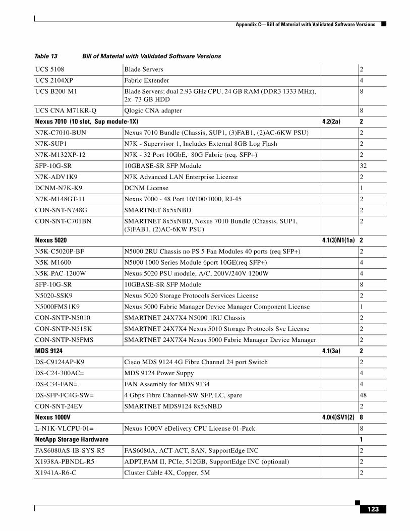
Appendix C—Bill of Material with Validated Software Versions
UCS 5108 Blade Servers 2
UCS 2104XP Fabric Extender 4
UCS B200-M1 Blade Servers; dual 2.93 GHz CPU, 24 GB RAM (DDR3 1333 MHz), 2x 73 GB HDD
8
UCS CNA M71KR-Q Qlogic CNA adapter 8
Nexus 7010 (10 slot, Sup module-1X) 4.2(2a) 2
N7K-C7010-BUN Nexus 7010 Bundle (Chassis, SUP1, (3)FAB1, (2)AC-6KW PSU) 2
N7K-SUP1 N7K - Supervisor 1, Includes External 8GB Log Flash 2
N7K-M132XP-12 N7K - 32 Port 10GbE, 80G Fabric (req. SFP+) 2
SFP-10G-SR 10GBASE-SR SFP Module 32
N7K-ADV1K9 N7K Advanced LAN Enterprise License 2
DCNM-N7K-K9 DCNM License 1
N7K-M148GT-11 Nexus 7000 - 48 Port 10/100/1000, RJ-45 2
CON-SNT-N748G SMARTNET 8x5xNBD 2
CON-SNT-C701BN SMARTNET 8x5xNBD, Nexus 7010 Bundle (Chassis, SUP1, (3)FAB1, (2)AC-6KW PSU)
2
Nexus 5020 4.1(3)N1(1a) 2
N5K-C5020P-BF N5000 2RU Chassis no PS 5 Fan Modules 40 ports (req SFP+) 2
N5K-M1600 N5000 1000 Series Module 6port 10GE(req SFP+) 4
N5K-PAC-1200W Nexus 5020 PSU module, A/C, 200V/240V 1200W 4
SFP-10G-SR 10GBASE-SR SFP Module 8
N5020-SSK9 Nexus 5020 Storage Protocols Services License 2
N5000FMS1K9 Nexus 5000 Fabric Manager Device Manager Component License 1
CON-SNTP-N5010 SMARTNET 24X7X4 N5000 1RU Chassis 2
CON-SNTP-N51SK SMARTNET 24X7X4 Nexus 5010 Storage Protocols Svc License 2
CON-SNTP-N5FMS SMARTNET 24X7X4 Nexus 5000 Fabric Manager Device Manager 2
MDS 9124 4.1(3a) 2
DS-C9124AP-K9 Cisco MDS 9124 4G Fibre Channel 24 port Switch 2
DS-C24-300AC= MDS 9124 Power Suppy 4
DS-C34-FAN= FAN Assembly for MDS 9134 4
DS-SFP-FC4G-SW= 4 Gbps Fibre Channel-SW SFP, LC, spare 48
CON-SNT-24EV SMARTNET MDS9124 8x5xNBD 2
Nexus 1000V 4.0(4)SV1(2) 8
L-N1K-VLCPU-01= Nexus 1000V eDelivery CPU License 01-Pack 8
NetApp Storage Hardware 1
FAS6080AS-IB-SYS-R5 FAS6080A, ACT-ACT, SAN, SupportEdge INC 2
X1938A-PBNDL-R5 ADPT,PAM II, PCIe, 512GB, SupportEdge INC (optional) 2
X1941A-R6-C Cluster Cable 4X, Copper, 5M 2
Table 13 Bill of Material with Validated Software Versions
123
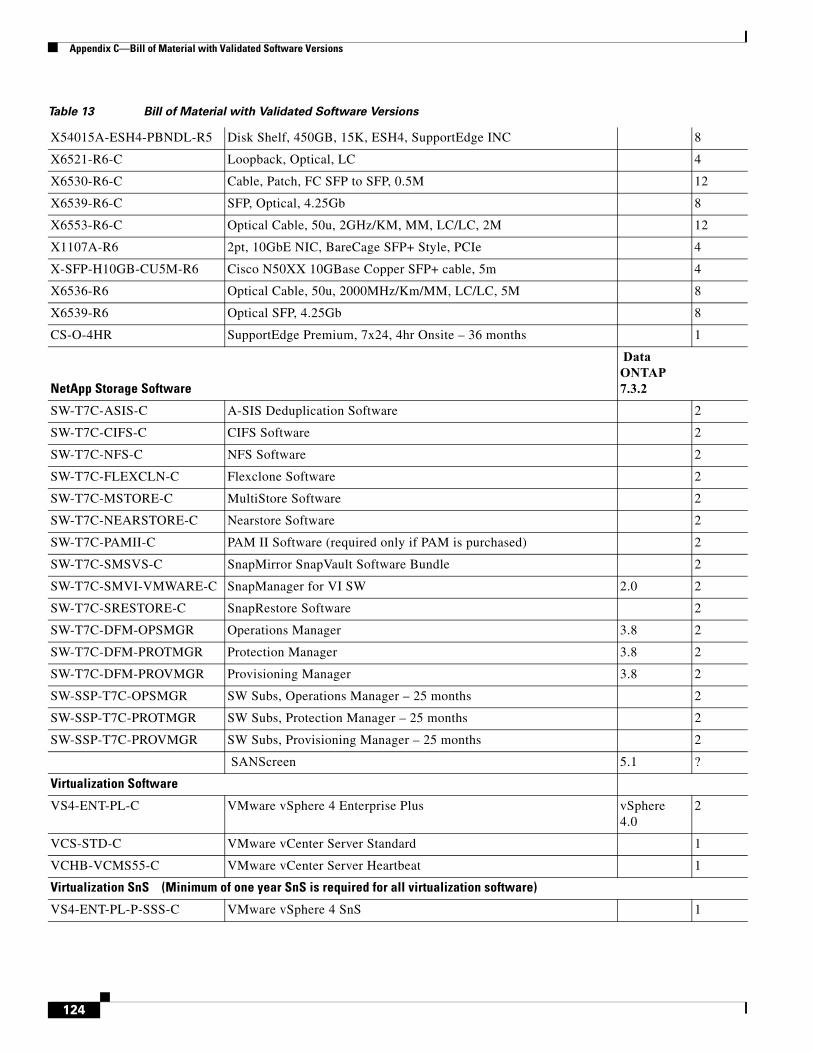
Appendix C—Bill of Material with Validated Software Versions
X54015A-ESH4-PBNDL-R5 Disk Shelf, 450GB, 15K, ESH4, SupportEdge INC 8
X6521-R6-C Loopback, Optical, LC 4
X6530-R6-C Cable, Patch, FC SFP to SFP, 0.5M 12
X6539-R6-C SFP, Optical, 4.25Gb 8
X6553-R6-C Optical Cable, 50u, 2GHz/KM, MM, LC/LC, 2M 12
X1107A-R6 2pt, 10GbE NIC, BareCage SFP+ Style, PCIe 4
X-SFP-H10GB-CU5M-R6 Cisco N50XX 10GBase Copper SFP+ cable, 5m 4
X6536-R6 Optical Cable, 50u, 2000MHz/Km/MM, LC/LC, 5M 8
X6539-R6 Optical SFP, 4.25Gb 8
CS-O-4HR SupportEdge Premium, 7x24, 4hr Onsite – 36 months 1
NetApp Storage Software
Data ONTAP 7.3.2
SW-T7C-ASIS-C A-SIS Deduplication Software 2
SW-T7C-CIFS-C CIFS Software 2
SW-T7C-NFS-C NFS Software 2
SW-T7C-FLEXCLN-C Flexclone Software 2
SW-T7C-MSTORE-C MultiStore Software 2
SW-T7C-NEARSTORE-C Nearstore Software 2
SW-T7C-PAMII-C PAM II Software (required only if PAM is purchased) 2
SW-T7C-SMSVS-C SnapMirror SnapVault Software Bundle 2
SW-T7C-SMVI-VMWARE-C SnapManager for VI SW 2.0 2
SW-T7C-SRESTORE-C SnapRestore Software 2
SW-T7C-DFM-OPSMGR Operations Manager 3.8 2
SW-T7C-DFM-PROTMGR Protection Manager 3.8 2
SW-T7C-DFM-PROVMGR Provisioning Manager 3.8 2
SW-SSP-T7C-OPSMGR SW Subs, Operations Manager – 25 months 2
SW-SSP-T7C-PROTMGR SW Subs, Protection Manager – 25 months 2
SW-SSP-T7C-PROVMGR SW Subs, Provisioning Manager – 25 months 2
SANScreen 5.1 ?
Virtualization Software
VS4-ENT-PL-C VMware vSphere 4 Enterprise Plus vSphere 4.0
2
VCS-STD-C VMware vCenter Server Standard 1
VCHB-VCMS55-C VMware vCenter Server Heartbeat 1
Virtualization SnS (Minimum of one year SnS is required for all virtualization software)
VS4-ENT-PL-P-SSS-C VMware vSphere 4 SnS 1
Table 13 Bill of Material with Validated Software Versions
124

Appendix C—Bill of Material with Validated Software Versions
VCS-STD-P-SSS-C VMware vCenter Sns 1
VCHB-VCMS-P-SSS-C VMware vCenter Server Heartbeat SnS 1
Table 13 Bill of Material with Validated Software Versions
125

Appendix C—Bill of Material with Validated Software Versions
126