Embed Size (px)
Citation preview
Remote Lab Guide
Version 1.5
Deploying Advanced
Cisco Wireless LANs (WDAWL)
2 Deploying Advanced Cisco Wireless LANs (WDAWL) v1.5 © 2018 Cisco Systems, Inc.
© 2018 GigaWave Technologies
Copyright 2018, Cisco Systems, Inc. All rights reserved.
Copyright 2018, GigaWave Technologies, All rights reserved.
© 2018 Cisco Systems, Inc. Remote Lab Guide 3
© 2018 GigaWave Technologies
Contents
Lab Guide ........................................................................................................................... 4
Overview .................................................................................................................................. 4
Outline ............................................................................................................................................. 4
Lab Topology Diagram ..................................................................................................................... 4
Lab Familiarization .................................................................................................................. 6
Overview ......................................................................................................................................... 6
Task 1: Navigate the Gigawave Remote Lab .................................................................................... 8
Task 2: Navigate the Interactive Diagram Page .............................................................................. 11
Task 3: Prepare the Client Laptop in the Remote Lab..................................................................... 14
Task 4: Configuring the WLC to Boot on the Backup Image ........................................................... 14
Task 5: Closing the Lab ................................................................................................................. 15
Lab 1-2: Configuring QoS on the Controller ....................................................................... 17
Task 1: Configure and Verify Throughput without Guest QoS Role on First Guest Account ............. 17
Task 2: Configure and Verify Throughput with Guest QoS Role on Second Guest Account ............ 22
Task 3: Closing the Lab ................................................................................................................. 26
Lab 1-3: Capturing and Analyzing QoS Parameters ........................................................... 27
Task 1: Verify Beacons and QoS Settings ...................................................................................... 27
Task 2: Change QoS Settings and Verify Impact on Beacons QoS Settings ................................... 32
Task 3: Closing the Lab ................................................................................................................. 39
Lab 2-1: Configuring IPv6 ..................................................................................................... 40
Task 1: Configure IPv6 on your Switch and WLC ........................................................................... 40
Task 2: Configure IPv6 on your WLC ............................................................................................. 41
Task 3: Verify IPv6 on your Client Laptop and Test IPv6 Connectivity ............................................ 42
Task 4: Closing the Lab ................................................................................................................. 43
Lab 2-2: IPv6 First Hop Security Configuration (Optional) ................................................. 44
Task 1: Configure IPv6 Support ..................................................................................................... 44
Task 2: Closing the Lab ................................................................................................................. 48
4 Deploying Advanced Cisco Wireless LANs (WDAWL) v1.5 © 2018 Cisco Systems, Inc.
© 2018 GigaWave Technologies
WDAWL
Lab Guide
Overview This guide presents the instructions and other information concerning the lab activities for this course.
Outline This guide includes these activities:
� Lab 1-1: Connecting to the Remote Labs
� Lab 1-2: Configuring QoS on the Controller
� Lab 1-3: Capturing and Analyzing QoS Parameters
� Lab 2-1: Configuring IPv6
� Lab 2-2: IPv6 First Hop Security Configuration (Optional)
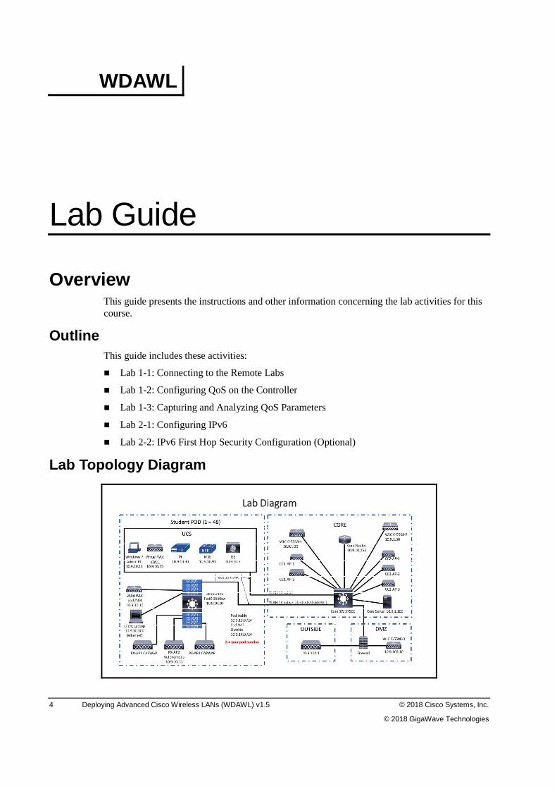
Lab Topology Diagram
Lab Diagram
© 2018 Cisco Systems, Inc. Remote Lab Guide 5
© 2018 GigaWave Technologies
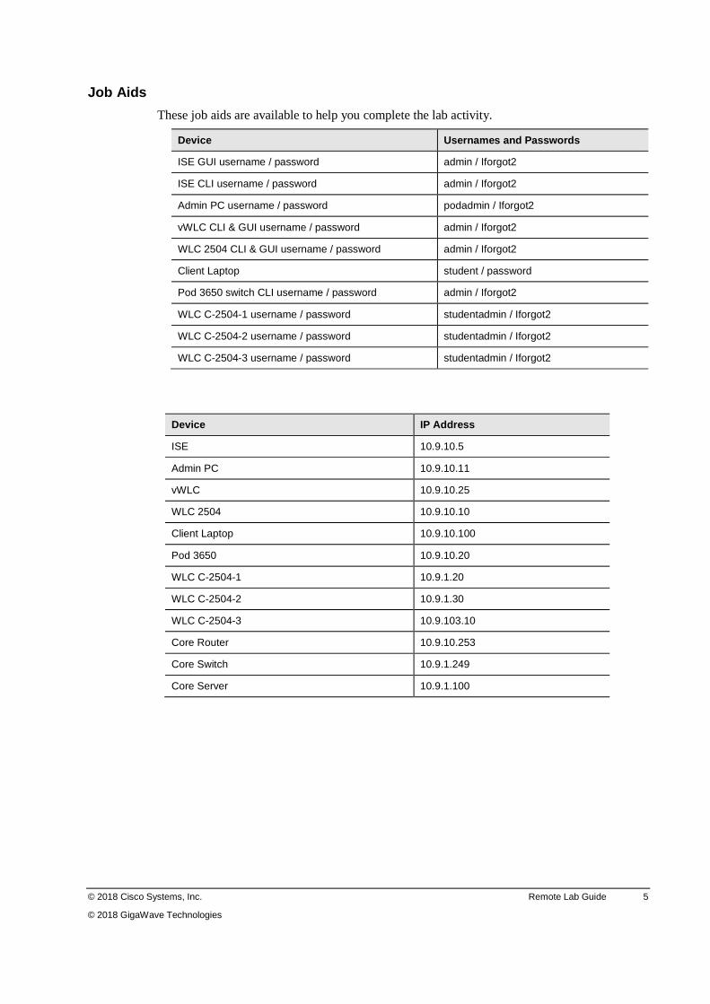
Job Aids
These job aids are available to help you complete the lab activity.
Device Usernames and Passwords
ISE GUI username / password admin / Iforgot2
ISE CLI username / password admin / Iforgot2
Admin PC username / password podadmin / Iforgot2
vWLC CLI & GUI username / password admin / Iforgot2
WLC 2504 CLI & GUI username / password admin / Iforgot2
Client Laptop student / password
Pod 3650 switch CLI username / password admin / Iforgot2
WLC C-2504-1 username / password studentadmin / Iforgot2
WLC C-2504-2 username / password studentadmin / Iforgot2
WLC C-2504-3 username / password studentadmin / Iforgot2
Device IP Address
ISE 10.9.10.5
Admin PC 10.9.10.11
vWLC 10.9.10.25
WLC 2504 10.9.10.10
Client Laptop 10.9.10.100
Pod 3650 10.9.10.20
WLC C-2504-1 10.9.1.20
WLC C-2504-2 10.9.1.30
WLC C-2504-3 10.9.103.10
Core Router 10.9.10.253
Core Switch 10.9.1.249
Core Server 10.9.1.100
6 Deploying Advanced Cisco Wireless LANs (WDAWL) v1.5 © 2018 Cisco Systems, Inc.
© 2018 GigaWave Technologies
Lab Familiarization Overview
In this activity, you will connect to the Gigawave remote lab. After completing this activity, you will be able to meet the objectives.
� Use the icons on the diagram page to open a CLI or VPN session
� Use the Session menu to open a CLI or VPN session
� Use the action key
� Use the icons page to activate scripts
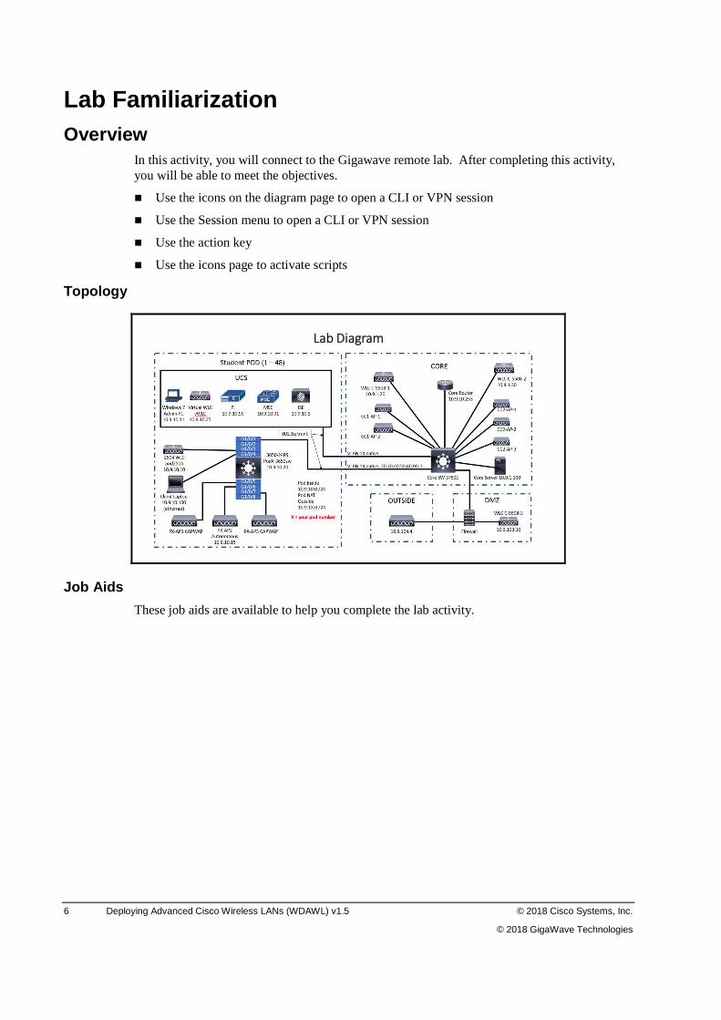
Topology
Lab Diagram
Job Aids
These job aids are available to help you complete the lab activity.
© 2018 Cisco Systems, Inc. Remote Lab Guide 7
© 2018 GigaWave Technologies
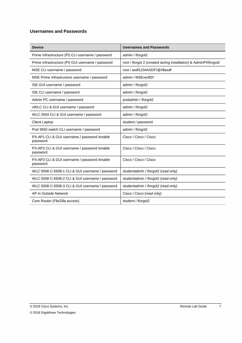
Usernames and Passwords
Device Usernames and Passwords
Prime Infrastructure (PI) CLI username / password admin / Iforgot2
Prime Infrastructure (PI) GUI username / password root / Iforgot 2 (created during installation) & AdminPI/Iforgot2
MSE CLI username / password root / asdf1234ASDF!@#$asdf
MSE Prime Infrastructure username / password admin / MSEver80!!
ISE GUI username / password admin / Iforgot2
ISE CLI username / password admin / Iforgot2
Admin PC username / password podadmin / Iforgot2
vWLC CLI & GUI username / password admin / Iforgot2
WLC 2504 CLI & GUI username / password admin / Iforgot2
Client Laptop student / password
Pod 3650 switch CLI username / password admin / Iforgot2
PX-AP1 CLI & GUI username / password /enable password
Cisco / Cisco / Cisco
PX-AP2 CLI & GUI username / password /enable password
Cisco / Cisco / Cisco
PX-AP3 CLI & GUI username / password /enable password
Cisco / Cisco / Cisco
WLC 5508 C-5508-1 CLI & GUI username / password studentadmin / Iforgot2 (read only)
WLC 5508 C-5508-2 CLI & GUI username / password studentadmin / Iforgot2 (read only)
WLC 5508 C-5508-3 CLI & GUI username / password studentadmin / Iforgot2 (read only)
AP in Outside Network Cisco / Cisco (read only)
Core Router (FileZilla access) student / Iforgot2
8 Deploying Advanced Cisco Wireless LANs (WDAWL) v1.5 © 2018 Cisco Systems, Inc.
© 2018 GigaWave Technologies
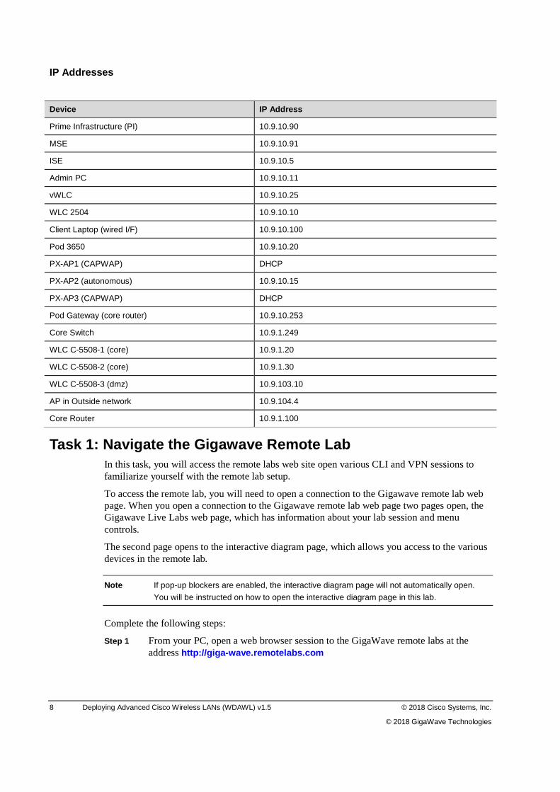
IP Addresses
Device IP Address
Prime Infrastructure (PI) 10.9.10.90
MSE 10.9.10.91
ISE 10.9.10.5
Admin PC 10.9.10.11
vWLC 10.9.10.25
WLC 2504 10.9.10.10
Client Laptop (wired I/F) 10.9.10.100
Pod 3650 10.9.10.20
PX-AP1 (CAPWAP) DHCP
PX-AP2 (autonomous) 10.9.10.15
PX-AP3 (CAPWAP) DHCP
Pod Gateway (core router) 10.9.10.253
Core Switch 10.9.1.249
WLC C-5508-1 (core) 10.9.1.20
WLC C-5508-2 (core) 10.9.1.30
WLC C-5508-3 (dmz) 10.9.103.10
AP in Outside network 10.9.104.4
Core Router 10.9.1.100
Task 1: Navigate the Gigawave Remote Lab In this task, you will access the remote labs web site open various CLI and VPN sessions to familiarize yourself with the remote lab setup.
To access the remote lab, you will need to open a connection to the Gigawave remote lab web page. When you open a connection to the Gigawave remote lab web page two pages open, the Gigawave Live Labs web page, which has information about your lab session and menu controls.
The second page opens to the interactive diagram page, which allows you access to the various devices in the remote lab.
Note If pop-up blockers are enabled, the interactive diagram page will not automatically open.
You will be instructed on how to open the interactive diagram page in this lab.
Complete the following steps:
Step 1 From your PC, open a web browser session to the GigaWave remote labs at the address http://giga-wave.remotelabs.com
© 2018 Cisco Systems, Inc. Remote Lab Guide 9
© 2018 GigaWave Technologies
Note The instructions in this Hardware Challenge Lab guide were created using Windows Internet
Explorer 11. If you are using your own laptop and select to use a different browser, some steps may be different.
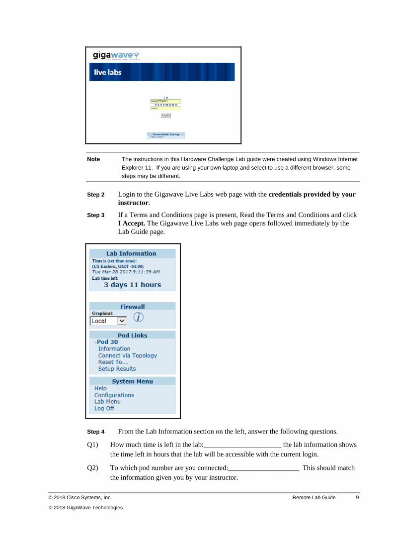
Step 2 Login to the Gigawave Live Labs web page with the credentials provided by your instructor .
Step 3 If a Terms and Conditions page is present, Read the Terms and Conditions and click I Accept. The Gigawave Live Labs web page opens followed immediately by the Lab Guide page.
Step 4 From the Lab Information section on the left, answer the following questions.
Q1) How much time is left in the lab:______________________ the lab information shows the time left in hours that the lab will be accessible with the current login.
Q2) To which pod number are you connected:____________________ This should match the information given you by your instructor.
10 Deploying Advanced Cisco Wireless LANs (WDAWL) v1.5 © 2018 Cisco Systems, Inc.
© 2018 GigaWave Technologies
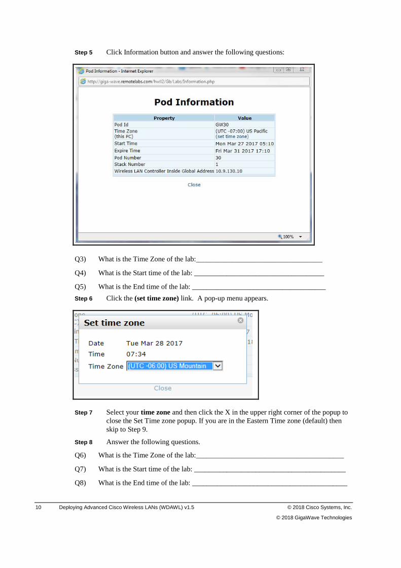
Step 5 Click Information button and answer the following questions:
Q3) What is the Time Zone of the lab:___________________________________
Q4) What is the Start time of the lab: ____________________________________
Q5) What is the End time of the lab: _____________________________________
Step 6 Click the (set time zone) link. A pop-up menu appears.
Step 7 Select your time zone and then click the X in the upper right corner of the popup to close the Set Time zone popup. If you are in the Eastern Time zone (default) then skip to Step 9.
Step 8 Answer the following questions.
Q6) What is the Time Zone of the lab:_________________________________________
Q7) What is the Start time of the lab: __________________________________________
Q8) What is the End time of the lab: ___________________________________________
© 2018 Cisco Systems, Inc. Remote Lab Guide 11
© 2018 GigaWave Technologies
Step 9 Close the Pod Information window. Notice that the time in the Lab Information window at the left has changed to the new time zone, if you changed the time zone. You may need to refresh your screen for the time zone change to show.
You can also change the time zone by clicking the (set time zone) link next to the Time is under the Lab Information page.
Step 10 Write the Lab time left down here:_____________. This is continuously running clock. The lab will be available at all times until the Lab time left expires.
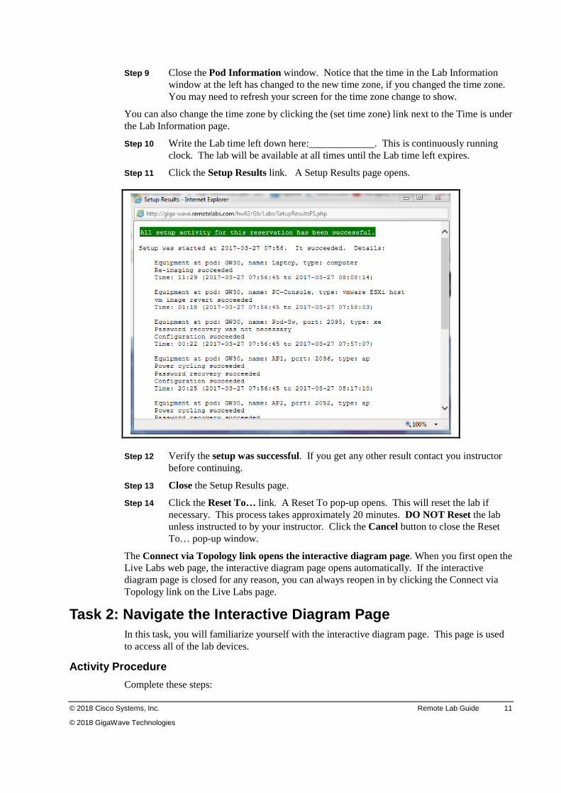
Step 11 Click the Setup Results link. A Setup Results page opens.
Step 12 Verify the setup was successful. If you get any other result contact you instructor before continuing.
Step 13 Close the Setup Results page.
Step 14 Click the Reset To… link. A Reset To pop-up opens. This will reset the lab if necessary. This process takes approximately 20 minutes. DO NOT Reset the lab unless instructed to by your instructor. Click the Cancel button to close the Reset To… pop-up window.
The Connect via Topology link opens the interactive diagram page. When you first open the Live Labs web page, the interactive diagram page opens automatically. If the interactive diagram page is closed for any reason, you can always reopen in by clicking the Connect via Topology link on the Live Labs page.
Task 2: Navigate the Interactive Diagram Page In this task, you will familiarize yourself with the interactive diagram page. This page is used to access all of the lab devices.
Activity Procedure
Complete these steps:
12 Deploying Advanced Cisco Wireless LANs (WDAWL) v1.5 © 2018 Cisco Systems, Inc.
© 2018 GigaWave Technologies
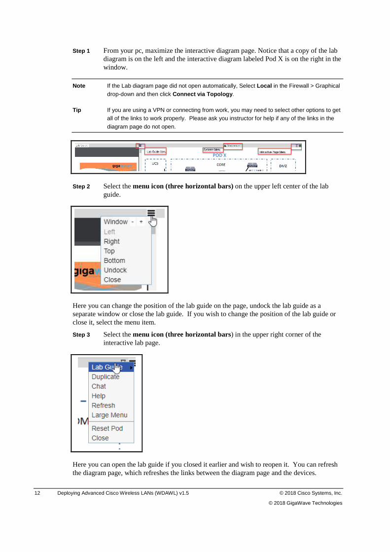
Step 1 From your pc, maximize the interactive diagram page. Notice that a copy of the lab diagram is on the left and the interactive diagram labeled Pod X is on the right in the window.
Note If the Lab diagram page did not open automatically, Select Local in the Firewall > Graphical
drop-down and then click Connect via Topology.
Tip If you are using a VPN or connecting from work, you may need to select other options to get all of the links to work properly. Please ask you instructor for help if any of the links in the
diagram page do not open.
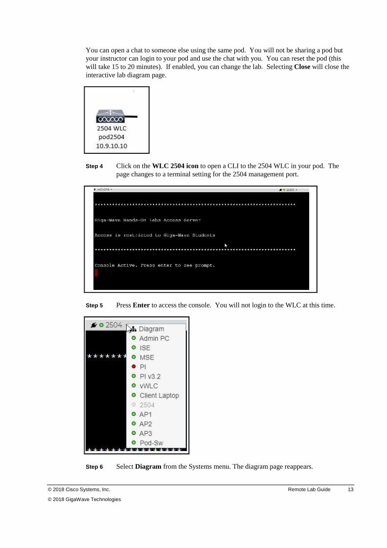
Step 2 Select the menu icon (three horizontal bars) on the upper left center of the lab guide.
Here you can change the position of the lab guide on the page, undock the lab guide as a separate window or close the lab guide. If you wish to change the position of the lab guide or close it, select the menu item.
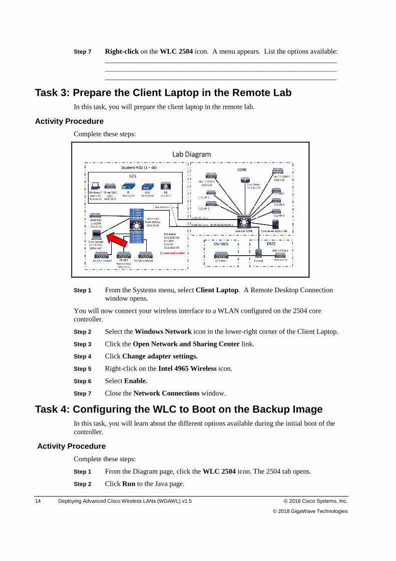
Step 3 Select the menu icon (three horizontal bars) in the upper right corner of the interactive lab page.
Here you can open the lab guide if you closed it earlier and wish to reopen it. You can refresh the diagram page, which refreshes the links between the diagram page and the devices.
© 2018 Cisco Systems, Inc. Remote Lab Guide 13
© 2018 GigaWave Technologies
You can open a chat to someone else using the same pod. You will not be sharing a pod but your instructor can login to your pod and use the chat with you. You can reset the pod (this will take 15 to 20 minutes). If enabled, you can change the lab. Selecting Close will close the interactive lab diagram page.
Step 4 Click on the WLC 2504 icon to open a CLI to the 2504 WLC in your pod. The page changes to a terminal setting for the 2504 management port.
Step 5 Press Enter to access the console. You will not login to the WLC at this time.
Step 6 Select Diagram from the Systems menu. The diagram page reappears.
14 Deploying Advanced Cisco Wireless LANs (WDAWL) v1.5 © 2018 Cisco Systems, Inc.
© 2018 GigaWave Technologies
Step 7 Right-click on the WLC 2504 icon. A menu appears. List the options available: _________________________________________________________________ _________________________________________________________________ _________________________________________________________________
Task 3: Prepare the Client Laptop in the Remote Lab In this task, you will prepare the client laptop in the remote lab.
Activity Procedure
Complete these steps:
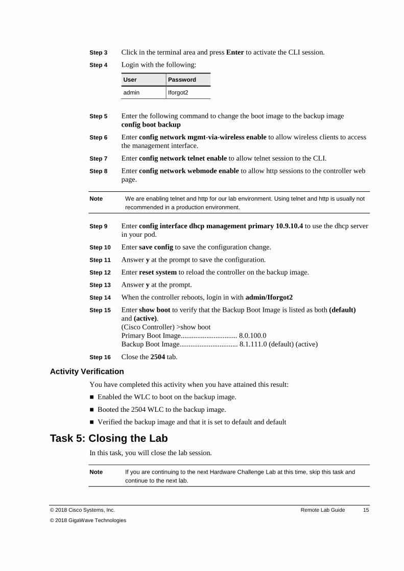
Lab Diagram
Step 1 From the Systems menu, select Client Laptop. A Remote Desktop Connection window opens.
You will now connect your wireless interface to a WLAN configured on the 2504 core controller.
Step 2 Select the Windows Network icon in the lower-right corner of the Client Laptop.
Step 3 Click the Open Network and Sharing Center link.
Step 4 Click Change adapter settings.
Step 5 Right-click on the Intel 4965 Wireless icon.
Step 6 Select Enable.
Step 7 Close the Network Connections window.
Task 4: Configuring the WLC to Boot on the Backup Image In this task, you will learn about the different options available during the initial boot of the controller.
Activity Procedure
Complete these steps:
Step 1 From the Diagram page, click the WLC 2504 icon. The 2504 tab opens.
Step 2 Click Run to the Java page.
© 2018 Cisco Systems, Inc. Remote Lab Guide 15
© 2018 GigaWave Technologies
Step 3 Click in the terminal area and press Enter to activate the CLI session.
Step 4 Login with the following:
User Password
admin Iforgot2
Step 5 Enter the following command to change the boot image to the backup image config boot backup
Step 6 Enter config network mgmt-via-wireless enable to allow wireless clients to access the management interface.
Step 7 Enter config network telnet enable to allow telnet session to the CLI.
Step 8 Enter config network webmode enable to allow http sessions to the controller web page.
Note We are enabling telnet and http for our lab environment. Using telnet and http is usually not
recommended in a production environment.
Step 9 Enter config interface dhcp management primary 10.9.10.4 to use the dhcp server in your pod.
Step 10 Enter save config to save the configuration change.
Step 11 Answer y at the prompt to save the configuration.
Step 12 Enter reset system to reload the controller on the backup image.
Step 13 Answer y at the prompt.
Step 14 When the controller reboots, login in with admin/Iforgot2
Step 15 Enter show boot to verify that the Backup Boot Image is listed as both (default) and (active). (Cisco Controller) >show boot Primary Boot Image............................... 8.0.100.0 Backup Boot Image................................ 8.1.111.0 (default) (active)
Step 16 Close the 2504 tab.
Activity Verification
You have completed this activity when you have attained this result:
� Enabled the WLC to boot on the backup image.
� Booted the 2504 WLC to the backup image.
� Verified the backup image and that it is set to default and default
Task 5: Closing the Lab In this task, you will close the lab session.
Note If you are continuing to the next Hardware Challenge Lab at this time, skip this task and
continue to the next lab.

16 Deploying Advanced Cisco Wireless LANs (WDAWL) v1.5 © 2018 Cisco Systems, Inc.
© 2018 GigaWave Technologies
Step 1 In the upper-right corner, click the X to close the Lab Topology Diagram.
© 2018 Cisco Systems, Inc. Remote Lab Guide 17
© 2018 GigaWave Technologies
Lab 1-2: Configuring QoS on the Controller Complete this lab activity to practice what you learned in the related module.
Activity Objective
In this lab, you will configure the wired and wireless infrastructures for QoS. After completing this activity, you will be able to meet these objectives:
� Configure and verify throughput for a normal guest user without QoS Role enabled
� Configure and verify throughput for a guest user restricted by Guest QoS Role
Required Resources
These are the resources and equipment required to complete this exercise:
� Cisco 2504 Series Wireless LAN Controller (WLC)
� Cisco Catalyst 3560E Series LAN Switch
� Cisco AP
� Student laptop
Task 1: Configure and Verify Throughput without Guest QoS Role on First Guest Account
In this task, you will test throughput without a QoS role. You will use a Web Auth WLAN to download a file and evaluate your throughput. You will then experiment with the per-user bandwidth contract. You will use the 2504 WLC for this lab.
Activity Procedure
Complete these steps:
If you are continuing from the previous lab, skip to Step 2.
Step 1 From your PC, open a web browser session to the GigaWave remote labs at the address http://giga-wave.remotelabs.com
Step 2 From the Systems menu, select Admin PC.
Step 3 Click the podadmin icon and enter Iforgot2 in the Password field.
Step 4 From the desktop of the Admin PC, open the Firefox browser and connect to the controller at https://10.9.10.10.
Step 5 Click I Understand the Risk at the Connection is Untrusted window.
Step 6 Click Add Exception.
Step 7 Click Confirm Security Exception. The Controller Login page opens.
Step 8 Log in to the 2504 WLC using the following values:
User Name Password
admin Iforgot2
18 Deploying Advanced Cisco Wireless LANs (WDAWL) v1.5 © 2018 Cisco Systems, Inc.
© 2018 GigaWave Technologies
Step 9 The 2504 WLC controller opens to the Dashboard page. Click the tool icon (looks like a round gear) in the upper-right corner of the browser and select Monitor Summary from the Landing Page drop-down menu.
Step 10 At the very top of the screen, select the Advanced link to open the Monitor Summary page on the 2504 WLC.
Step 11 In the upper menu, click WLANs.
Step 12 Select Create New and then click GO to create WEBAUTH WLAN.
Step 13 In the Profile Name filed, enter WEBAUTH.
Step 14 In the SSID field, enter WEBAUTH-X, where X is your pod number and click Apply.
Step 15 In the General tab, check the Status Enabled check box.
Step 16 Choose the Security tab.
Step 17 In the Layer 2 Security drop-down menu, choose None. This configures the WLAN for 802.11 Open authentication.
Step 18 Click Layer 3 tab.
Step 19 Select Web Policy in the Layer 3 Security drop-down menu.
Step 20 Click Apply to enable the changes in the new WLAN.
Step 21 Read the warning and click OK.
Step 22 Click Save Configuration.
Step 23 Click OK on the pop-up windows.
Step 24 In the upper menu, click SECURITY . You want to use local authentication for this WLAN.
Step 25 In the left menu, navigate to AAA > Local Net Users.
Step 26 You want to create a first user for a standard Web Authentication, without any specific bandwidth contract. Click New to create a new user. The Local Net Users > New page opens.
Step 27 In User Name field, enter student-1.
Step 28 In Password and Confirm Password fields, enter Iforgot2.
Step 29 Do not click Guest User. You will create a guest user later in this lab.
Step 30 In WLAN Profile field, choose WEBAUTH for the profile.
Step 31 In Description field, enter WebAuth user no restrictions as description for your first webauth user.
Step 32 Click Apply to create this user. Your user should appear in the list. It should not be a guest user and should not have any guest role. This means that this user does not have any specific bandwidth restriction.
Step 33 Minimize the web browser window. You will now need to test this user connection and throughput. To do this, you need to associate to the WEBAUTH SSID WLAN.
Step 34 From the Systems menu, select Client Laptop.
Step 35 Click on the orange flower icon and enter password in the PODLAPTOP\student user password field to login to the Client Laptop.
© 2018 Cisco Systems, Inc. Remote Lab Guide 19
© 2018 GigaWave Technologies
Step 36 From your Client Laptop, click the wireless network icon at the bottom right of your screen.
Step 37 In the list of SSIDs, you should see one named WEBAUTH-X, where X is your pod number. Click the SSID and click Connect.
Step 38 Verify that you are connected to WEBAUTH-X by clicking on the wireless network icon.
Step 39 Use Firefox to open a HTTP session to http://test.gigawave.trn. Use HTTP and not HTTPS. Make sure that your browser pop-up blocker is disabled. Because you are using a Web Auth WLAN, you are redirected to an initial web authentication page at the address of 192.168.10.10. You need to authenticate to access the network.
Step 40 Use the credentials that you created previously in this task. The User Name should be student-1 and the Password is Iforgot2.
Step 41 You are redirected to the controller web interface. Click Login.
Step 42 A pop-up window asks for your credentials. Login using admin / Iforgot2.
Step 43 You should see the controller Monitor page. You are now connected using the WEBAUTH-X profile.
You will use FileZilla to test the throughput of the wireless connection. First you will need to download the application and install it.
Step 44 From the Client Laptop, minimize the web browser to the controller to make the desktop visible.
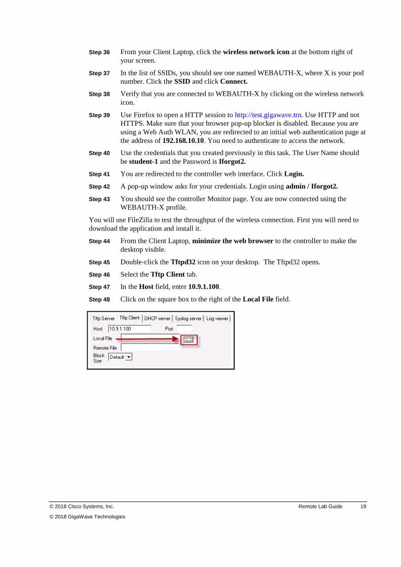
Step 45 Double-click the Tftpd32 icon on your desktop. The Tftpd32 opens.
Step 46 Select the Tftp Client tab.
Step 47 In the Host field, enter 10.9.1.100.
Step 48 Click on the square box to the right of the Local File field.
20 Deploying Advanced Cisco Wireless LANs (WDAWL) v1.5 © 2018 Cisco Systems, Inc.
© 2018 GigaWave Technologies
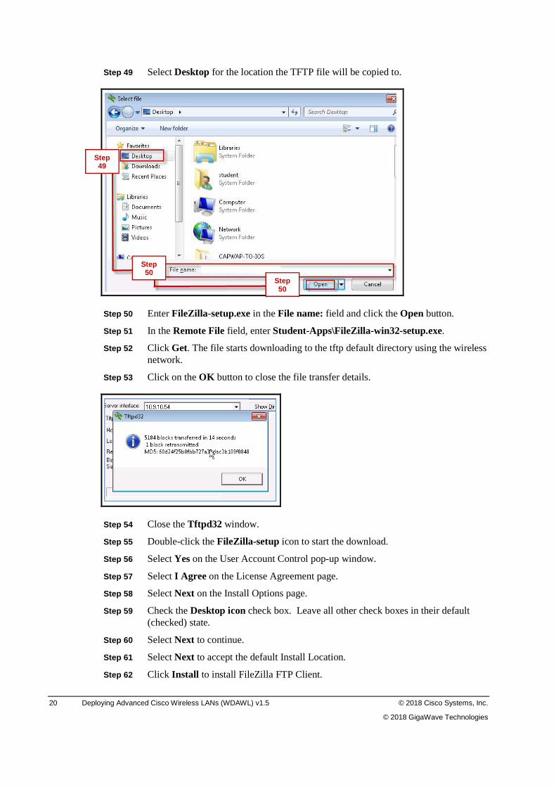
Step 49 Select Desktop for the location the TFTP file will be copied to.
Step 50 Enter FileZilla-setup.exe in the File name: field and click the Open button.
Step 51 In the Remote File field, enter Student-Apps\FileZilla-win32-setup.exe.
Step 52 Click Get. The file starts downloading to the tftp default directory using the wireless network.
Step 53 Click on the OK button to close the file transfer details.
Step 54 Close the Tftpd32 window.
Step 55 Double-click the FileZilla-setup icon to start the download.
Step 56 Select Yes on the User Account Control pop-up window.
Step 57 Select I Agree on the License Agreement page.
Step 58 Select Next on the Install Options page.
Step 59 Check the Desktop icon check box. Leave all other check boxes in their default (checked) state.
Step 60 Select Next to continue.
Step 61 Select Next to accept the default Install Location.
Step 62 Click Install to install FileZilla FTP Client.
Step 49
Step 50
Step 50
© 2018 Cisco Systems, Inc. Remote Lab Guide 21
© 2018 GigaWave Technologies
Step 63 Click OK to the Welcome to FileZilla.
Step 64 Click Finish. A FileZilla client icon appears on your desktop.
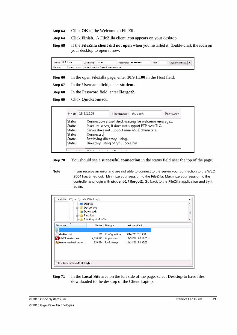
Step 65 If the FileZilla client did not open when you installed it, double-click the icon on your desktop to open it now.
Step 66 In the open FileZilla page, enter 10.9.1.100 in the Host field.
Step 67 In the Username field, enter student.
Step 68 In the Password field, enter Iforgot2.
Step 69 Click Quickconnect.
Step 70 You should see a successful connection in the status field near the top of the page.
Note If you receive an error and are not able to connect to the server your connection to the WLC
2504 has timed out. Minimize your session to the FileZilla. Maximize your session to the
controller and login with student-1 / Iforgot2. Go back to the FileZilla application and try it again.
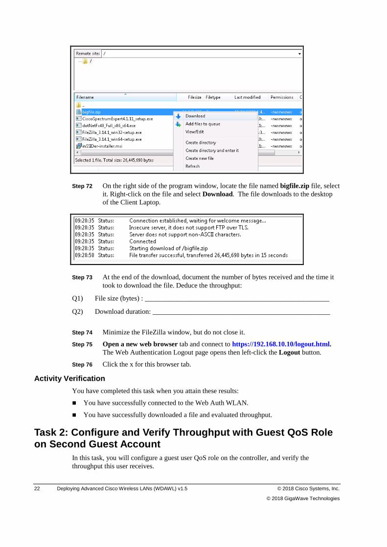
Step 71 In the Local Site area on the left side of the page, select Desktop to have files downloaded to the desktop of the Client Laptop.
22 Deploying Advanced Cisco Wireless LANs (WDAWL) v1.5 © 2018 Cisco Systems, Inc.
© 2018 GigaWave Technologies
Step 72 On the right side of the program window, locate the file named bigfile.zip file, select it. Right-click on the file and select Download. The file downloads to the desktop of the Client Laptop.
Step 73 At the end of the download, document the number of bytes received and the time it took to download the file. Deduce the throughput:
Q1) File size (bytes) : _____________________________________________________
Q2) Download duration: ___________________________________________________
Step 74 Minimize the FileZilla window, but do not close it.
Step 75 Open a new web browser tab and connect to https://192.168.10.10/logout.html. The Web Authentication Logout page opens then left-click the Logout button.
Step 76 Click the x for this browser tab.
Activity Verification
You have completed this task when you attain these results:
� You have successfully connected to the Web Auth WLAN.
� You have successfully downloaded a file and evaluated throughput.
Task 2: Configure and Verify Throughput with Guest QoS Role on Second Guest Account
In this task, you will configure a guest user QoS role on the controller, and verify the throughput this user receives.
© 2018 Cisco Systems, Inc. Remote Lab Guide 23
© 2018 GigaWave Technologies
Activity Procedure
Complete these steps:
Step 1 From the Systems menu, select Admin PC.
Step 2 Open a Firefox browser session to the Cisco 2504 WLC at https://10.9.10.10.
Step 3 Select WIRELESS from the top menu.
Step 4 In the left menu, navigate to QoS > Roles.
Step 5 Click New to create a new role.
Step 6 In Role Name field, enter Limited.
Step 7 Click Apply to validate the changes. Your guest user role name now appears in the list.
Step 8 Click Limited in the list to edit its settings.
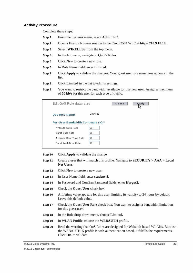
Step 9 You want to restrict the bandwidth available for this new user. Assign a maximum of 50 kb/s for this user for each type of traffic.
Step 10 Click Apply to validate the change.
Step 11 Create a user that will match this profile. Navigate to SECURITY > AAA > Local Net Users.
Step 12 Click New to create a new user.
Step 13 In User Name field, enter student-2.
Step 14 In Password and Confirm Password fields, enter Iforgot2.
Step 15 Check the Guest User check box.
Step 16 A lifetime value appears for this user, limiting its validity to 24 hours by default. Leave this default value.
Step 17 Check the Guest User Role check box. You want to assign a bandwidth limitation for this guest user.
Step 18 In the Role drop-down menu, choose Limited.
Step 19 In WLAN Profile, choose the WEBAUTH profile.
Step 20 Read the warning that QoS Roles are designed for Webauth-based WLANs. Because the WEBAUTH-X profile is web-authentication based, it fulfills the requirements. Click OK to validate.
24 Deploying Advanced Cisco Wireless LANs (WDAWL) v1.5 © 2018 Cisco Systems, Inc.
© 2018 GigaWave Technologies
Step 21 In the Description field, enter Guest with limited bandwidth.
Step 22 Click Apply to validate. The new user appears in the list.
Step 23 From the Systems menu, select Client Laptop.
Step 24 Click the wireless network icon at the bottom right of your screen.
Step 25 In the list of SSIDs, you should see one named WEBAUTH-X where X is your pod number. Click the SSID and click Connect. After a few seconds, the laptop connection status should switch to Connected.
Step 26 Open a command prompt and enter ipconfig /all.
Step 27 You should see in the list your wireless interface with its MAC address. Document your Client MAC and IPv4 address here: ____________________________________________________________________
Step 28 Close the Command Prompt window.
Step 29 Use Firefox to open a HTTP session to the class 2504 controller at http://10.9.10.10. Use HTTP, not HTTPS. Make sure that your browser pop-up blocker is disabled.
Step 30 Because you are using a Web Auth WLAN, you are redirected to an initial web authentication page at the address 192.168.10.10. You need to authenticate to access the network. In the User name field, enter student-2.
Step 31 In the Password field, enter Iforgot2.
Step 32 You are redirected to the controller web interface. Click Login.
Step 33 A pop-up window asks for your credentials. Sign in using admin / Iforgot2.
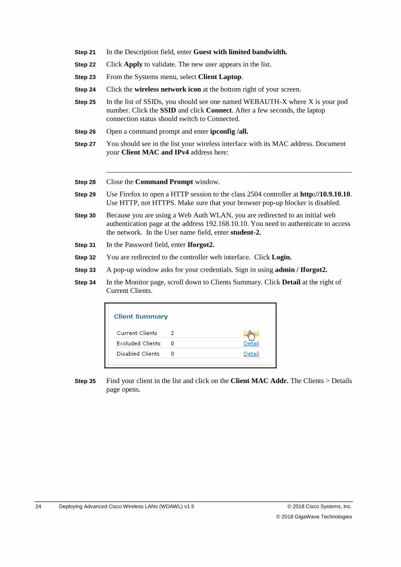
Step 34 In the Monitor page, scroll down to Clients Summary. Click Detail at the right of Current Clients.
Step 35 Find your client in the list and click on the Client MAC Addr. The Clients > Details page opens.
© 2018 Cisco Systems, Inc. Remote Lab Guide 25
© 2018 GigaWave Technologies
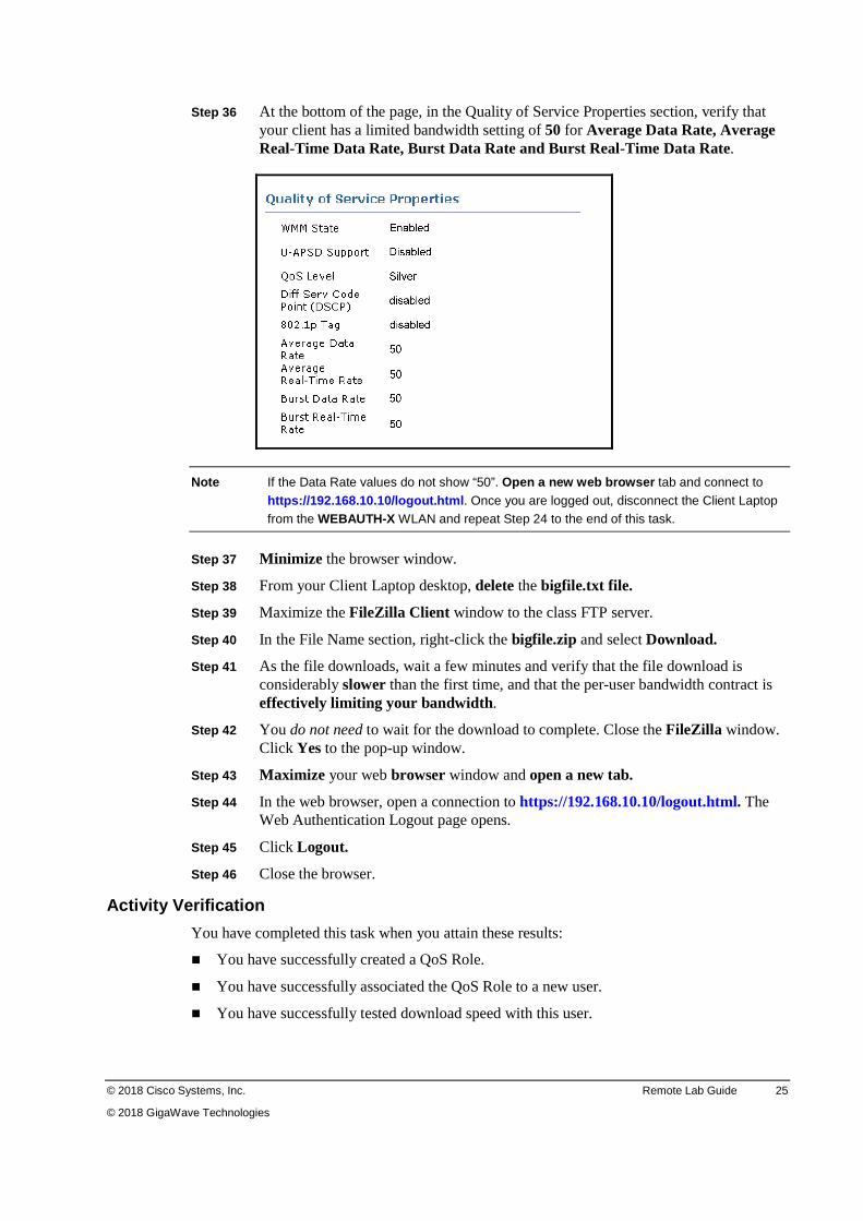
Step 36 At the bottom of the page, in the Quality of Service Properties section, verify that your client has a limited bandwidth setting of 50 for Average Data Rate, Average Real-Time Data Rate, Burst Data Rate and Burst Real-Time Data Rate.
Note If the Data Rate values do not show “50”. Open a new web browser tab and connect to
https://192.168.10.10/logout.html. Once you are logged out, disconnect the Client Laptop from the WEBAUTH-X WLAN and repeat Step 24 to the end of this task.
Step 37 Minimize the browser window.
Step 38 From your Client Laptop desktop, delete the bigfile.txt file.
Step 39 Maximize the FileZilla Client window to the class FTP server.
Step 40 In the File Name section, right-click the bigfile.zip and select Download.
Step 41 As the file downloads, wait a few minutes and verify that the file download is considerably slower than the first time, and that the per-user bandwidth contract is effectively limiting your bandwidth .
Step 42 You do not need to wait for the download to complete. Close the FileZilla window. Click Yes to the pop-up window.
Step 43 Maximize your web browser window and open a new tab.
Step 44 In the web browser, open a connection to https://192.168.10.10/logout.html. The Web Authentication Logout page opens.
Step 45 Click Logout.
Step 46 Close the browser.
Activity Verification
You have completed this task when you attain these results:
� You have successfully created a QoS Role.
� You have successfully associated the QoS Role to a new user.
� You have successfully tested download speed with this user.
26 Deploying Advanced Cisco Wireless LANs (WDAWL) v1.5 © 2018 Cisco Systems, Inc.
© 2018 GigaWave Technologies
Task 3: Closing the Lab In this task, you will close the lab session.
Note If you are continuing to the next Hardware Challenge Lab at this time, skip this task and
continue to the next lab.
Step 1 Select Diagram from the Systems menu.
Step 2 In the upper-right corner, click the X to close the Lab Topology Diagram.
© 2018 Cisco Systems, Inc. Remote Lab Guide 27
© 2018 GigaWave Technologies
Lab 1-3: Capturing and Analyzing QoS Parameters Complete this lab activity to practice what you learned in the related module.
Activity Objective
In this lab, you will test how the QoS parameters defined in the previous lab are seen in the wireless communication between the AP and the wireless cell. To test these parameters, you will try several QoS configuration parameters on the Cisco WLC and each time capture the AP beacons with Wireshark to carefully examine the QoS section of the frame. This allows you to understand what information your phone receives when connecting to the wireless network. Upon completion of this lab, you will be able to achieve the following objectives:
� Verify beacons and QoS settings
� Change WLAN QoS settings and verify impact on the WLAN
� Change the cell QoS level and verify its impact on the WLAN
Required Resources
These are the resources and equipment required to complete this exercise:
� Cisco 2504 Series WLC
� Catalyst Series LAN Switch
� Cisco AP
� Student laptop
Task 1: Verify Beacons and QoS Settings In this task, you will use Wireshark to capture the AP beacons and check their QoS settings with a WLAN Platinum and WMM-allowed QoS configuration. You will configure one of your APs as a remote sensor for Wireshark.
Activity Procedure
Complete these steps:
If you are continuing from the previous lab, skip to Step 2.
Step 1 From your PC, open a web browser session to the GigaWave remote labs at the address http://giga-wave.remotelabs.com
Step 2 From the Systems drop-down, select Admin PC.
Note If the session to the Admin PC is terminated. Select podadmin and enter Iforgot2 in the
Password field and press Enter. The Admin PC opens to the desktop.
Step 3 From the desktop of the Admin PC, open a Firefox browser and connect to the controller at https://10.9.10.10.
28 Deploying Advanced Cisco Wireless LANs (WDAWL) v1.5 © 2018 Cisco Systems, Inc.
© 2018 GigaWave Technologies
Step 4 Log in using the following values:
User Name Password
admin Iforgot2
Step 5 Select WLANs from the top menu.
Step 6 Select WLAN ID 1 to open the profile startup.
Step 7 In the SSID field, edit startup by placing an –X, where X is your pod number behind startup. For example, startup-47.
Step 8 Check the Status Enabled check box.
Step 9 From the Radio Policy drop-down menu, select 802.11b/g only.
Step 10 Select the Security tab.
Step 11 In the Layer 2 sub-tab, enable PSK in the Authentication Key Management area.
Step 12 Ensure that ASCII is selected in the PSK Format drop-down.
Step 13 Enter Iforgot2 in the PSK blank field.
Step 14 Select the QoS tab.
Step 15 In the Quality of Service (QoS) drop-down menu, select Platinum (voice).
Step 16 Click Apply to activate the changes. Read the pop-up window and click OK.
Step 17 Click Save Configuration to save the changes.
Step 18 Read the pop-up messages and click OK to both.
Step 19 Navigate to WIRELESS > Access Points > Radios > 802.11b/g/n.
Step 20 Scroll to the right and record the Channel assigned by RRM for PX-AP1. ________
Step 21 Position your cursor on the blue arrow at the end of the line for PX-AP1 and choose Configure.
Step 22 In the RF Channel assignment area, select Custom as the Assignment Method and choose the channel recorded above.
Step 23 In the Tx Power Level Assignment area, select Custom level and choose 1 from the drop-down menu. This ensures that AP3 can hear the beacons issued by AP1.
Step 24 Click Apply to save the changes. Read the pop-up window and click OK.
Step 25 In the left menu, navigate to Access Points > All APs.
Step 26 Select the PX-AP3 link. The All APs > Details for PX-AP3 opens.
Step 27 In the AP Mode drop-down menu, select Sniffer.
Step 28 Click Apply. Read the warning about the AP rebooting and click OK. Wait for the AP to rejoin the controller before continuing. Click Refresh periodically until the AP rejoins the controller.
Step 29 Navigate to WIRELESS > Access Points > Radios > 802.11b/g/n.
Step 30 Scroll to the right and select Configure from the blue box for PX-AP3.
Step 31 In the Sniffer channel Assignment area, check the Sniff check box to enable sniffing on the radio for AP3.
© 2018 Cisco Systems, Inc. Remote Lab Guide 29
© 2018 GigaWave Technologies
Step 32 Select the channel number recorded above for AP1 in the Channel drop-down menu.
Step 33 In the Server IP Address field, enter 10.9.10.100 (the ip address of the Client Laptop).
Step 34 Click Apply to save the changes to the AP.
Step 35 Click Back to return to the 802.11b/g/n Radios page.
Step 36 From the Systems menu, select Client Laptop. Login with password.
Step 37 Click the wireless network icon in the lower right of the screen.
Step 38 Click Open Network and Sharing Center.
Step 39 Click Change Adapter Settings.
Step 40 Right-click the Local Area Connection, Realtek PCIe GBE Family Controller and select Enable.
Step 41 Close the Network Connection window.
Step 42 From your Client Laptop, right-click the Wireshark shortcut.
Step 43 Select Run as administrator.
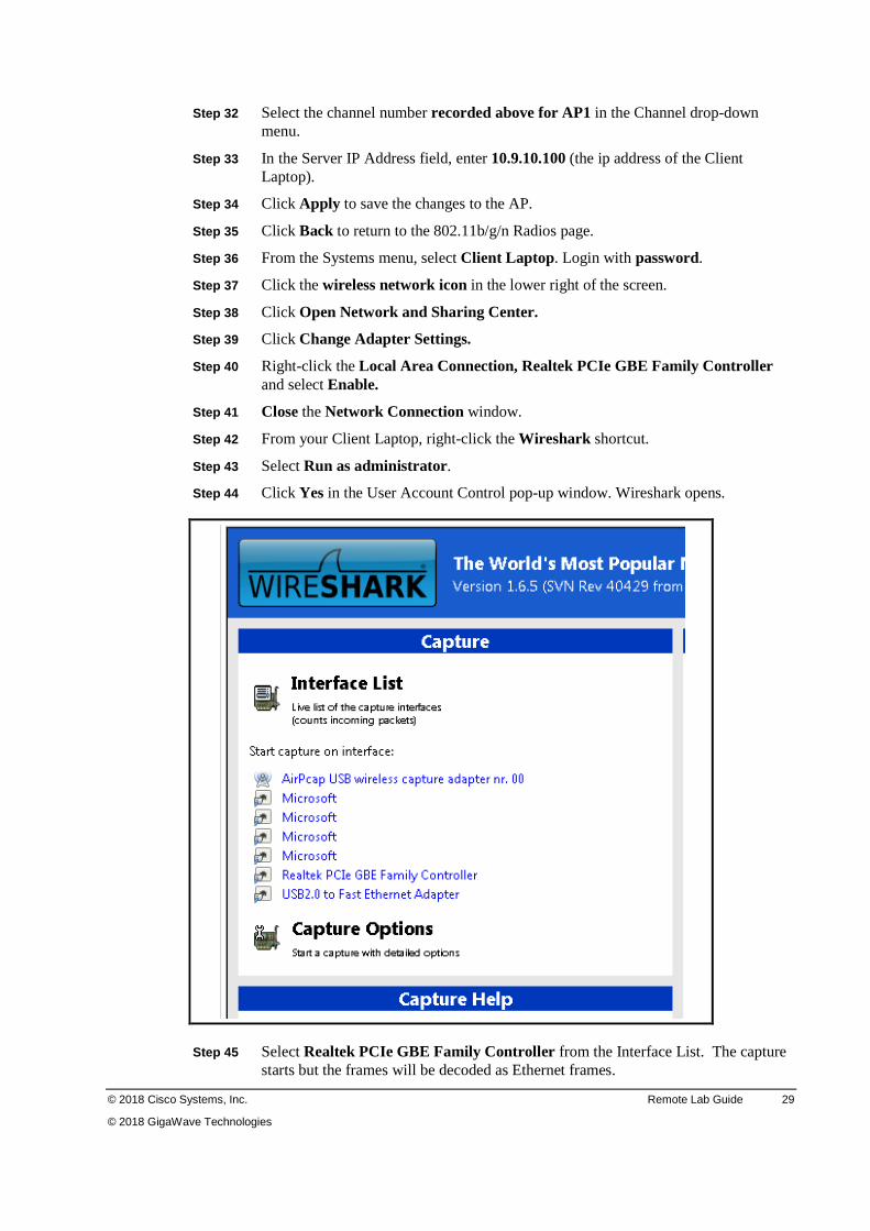
Step 44 Click Yes in the User Account Control pop-up window. Wireshark opens.
Step 45 Select Realtek PCIe GBE Family Controller from the Interface List. The capture starts but the frames will be decoded as Ethernet frames.
30 Deploying Advanced Cisco Wireless LANs (WDAWL) v1.5 © 2018 Cisco Systems, Inc.
© 2018 GigaWave Technologies
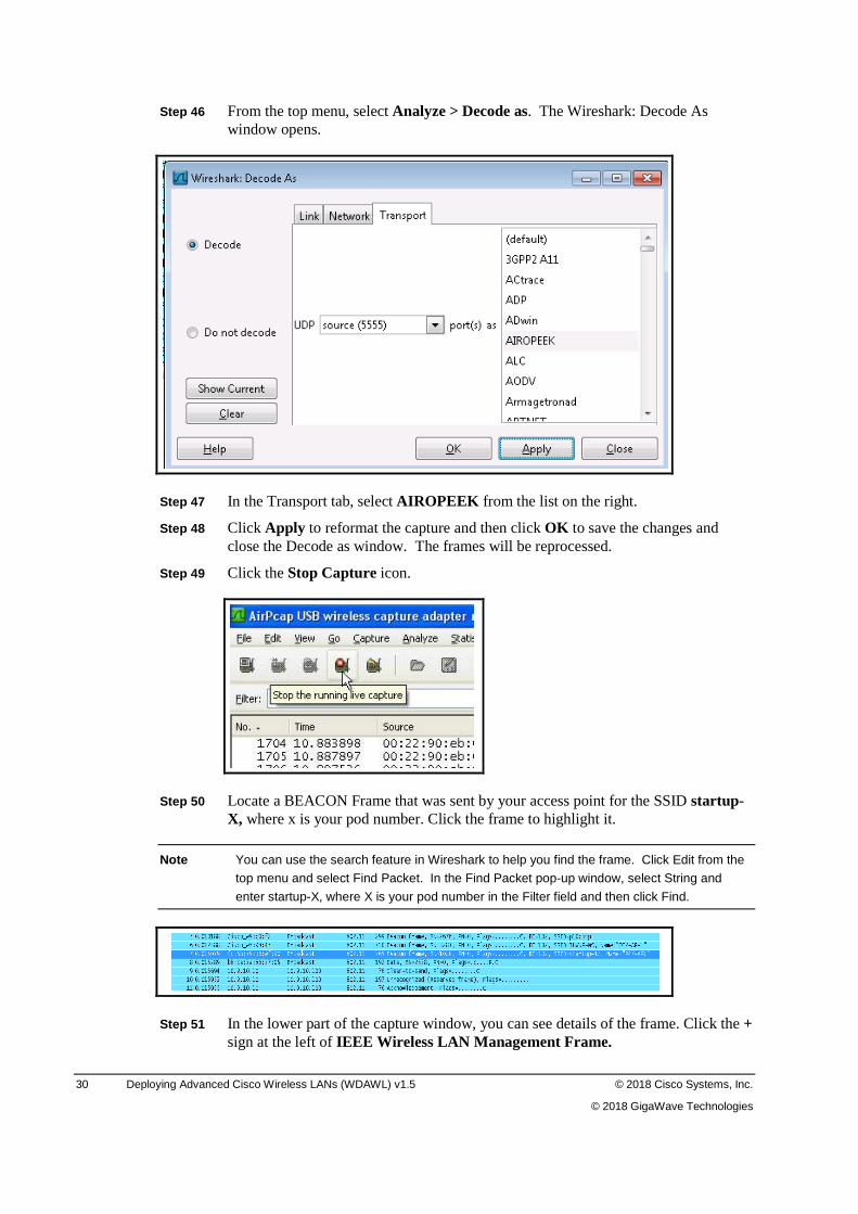
Step 46 From the top menu, select Analyze > Decode as. The Wireshark: Decode As window opens.
Step 47 In the Transport tab, select AIROPEEK from the list on the right.
Step 48 Click Apply to reformat the capture and then click OK to save the changes and close the Decode as window. The frames will be reprocessed.
Step 49 Click the Stop Capture icon.
Step 50 Locate a BEACON Frame that was sent by your access point for the SSID startup-X, where x is your pod number. Click the frame to highlight it.
Note You can use the search feature in Wireshark to help you find the frame. Click Edit from the
top menu and select Find Packet. In the Find Packet pop-up window, select String and
enter startup-X, where X is your pod number in the Filter field and then click Find.
Step 51 In the lower part of the capture window, you can see details of the frame. Click the + sign at the left of IEEE Wireless LAN Management Frame.
© 2018 Cisco Systems, Inc. Remote Lab Guide 31
© 2018 GigaWave Technologies
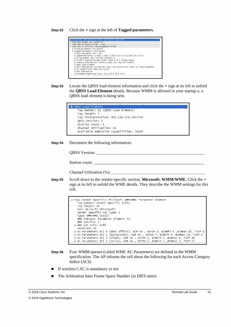
Step 52 Click the + sign at the left of Tagged parameters.
Step 53 Locate the QBSS load element information and click the + sign at its left to unfold the QBSS Load Element details. Because WMM is allowed in your startup-x, a QBSS load element is being sent.
Step 54 Document the following information: QBSS Version: ____________________________________________________ Station count: _____________________________________________________ Channel Utilization (%): _____________________________________________
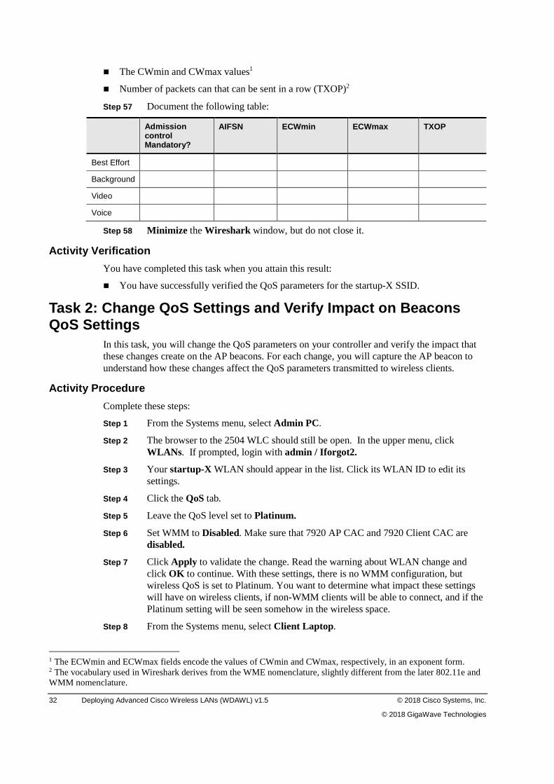
Step 55 Scroll down to the vendor-specific section, Microsoft: WMM/WME. Click the + sign at its left to unfold the WME details. They describe the WMM settings for this cell.
Step 56 Four WMM queues (called WME AC Parameters) are defined in the WMM specification. The AP informs the cell about the following for each Access Category Indice (ACI):
� If wireless CAC is mandatory or not
� The Arbitration Inter Frame Space Number (in DIFS units)
32 Deploying Advanced Cisco Wireless LANs (WDAWL) v1.5 © 2018 Cisco Systems, Inc.
© 2018 GigaWave Technologies
� The CWmin and CWmax values1
� Number of packets can that can be sent in a row (TXOP)2
Step 57 Document the following table:
Admission control Mandatory?
AIFSN ECWmin ECWmax TXOP
Best Effort
Background
Video
Voice
Step 58 Minimize the Wireshark window, but do not close it.
Activity Verification
You have completed this task when you attain this result:
� You have successfully verified the QoS parameters for the startup-X SSID.
Task 2: Change QoS Settings and Verify Impact on Beacons QoS Settings
In this task, you will change the QoS parameters on your controller and verify the impact that these changes create on the AP beacons. For each change, you will capture the AP beacon to understand how these changes affect the QoS parameters transmitted to wireless clients.
Activity Procedure
Complete these steps:
Step 1 From the Systems menu, select Admin PC.
Step 2 The browser to the 2504 WLC should still be open. In the upper menu, click WLANs . If prompted, login with admin / Iforgot2.
Step 3 Your startup-X WLAN should appear in the list. Click its WLAN ID to edit its settings.
Step 4 Click the QoS tab.
Step 5 Leave the QoS level set to Platinum.
Step 6 Set WMM to Disabled. Make sure that 7920 AP CAC and 7920 Client CAC are disabled.
Step 7 Click Apply to validate the change. Read the warning about WLAN change and click OK to continue. With these settings, there is no WMM configuration, but wireless QoS is set to Platinum. You want to determine what impact these settings will have on wireless clients, if non-WMM clients will be able to connect, and if the Platinum setting will be seen somehow in the wireless space.
Step 8 From the Systems menu, select Client Laptop.
1 The ECWmin and ECWmax fields encode the values of CWmin and CWmax, respectively, in an exponent form. 2 The vocabulary used in Wireshark derives from the WME nomenclature, slightly different from the later 802.11e and WMM nomenclature.
© 2018 Cisco Systems, Inc. Remote Lab Guide 33
© 2018 GigaWave Technologies
Step 9 Maximize the Wireshark window.
Step 10 Click Capture > Start.
Step 11 Read the warning about lost information and click Continue Without Saving.
Step 12 Let the capture run a few seconds and then click the Stop Capture icon.
Step 13 From the many packets in the capture, find one that was sent by your access point for the SSID startup-X, where X is your pod number. Click it to highlight it.
Step 14 In the lower part of the capture window, you can see details of the frame. Click the + sign at the left of IEEE Wireless Management Frame.
Step 15 Click the + sign at the left of Tagged parameters. Verify the following:
� The QBSS information element is not present. WMM is disabled in this WLAN, so the QBSS element is no longer sent.
� The Microsoft WMM/WME element is not present. There is no QoS information in the beacons, and the Platinum information is nowhere to be seen in these beacons.
Step 16 Minimize, but do not close Wireshark.
Step 17 From the Systems menu, select Admin PC.
Step 18 In the upper menu, click WLANs .
Step 19 Click the WLAN ID for the profile startup to edit its settings.
Step 20 Click the QoS tab.
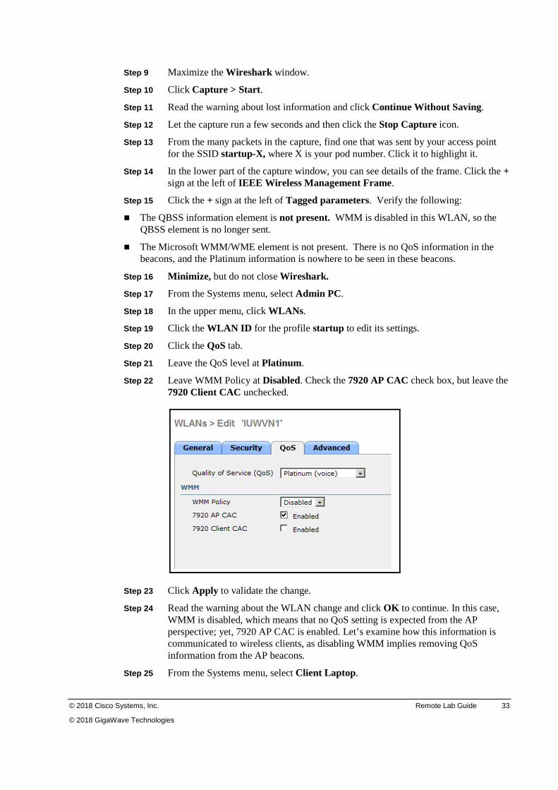
Step 21 Leave the QoS level at Platinum.
Step 22 Leave WMM Policy at Disabled. Check the 7920 AP CAC check box, but leave the 7920 Client CAC unchecked.
Step 23 Click Apply to validate the change.
Step 24 Read the warning about the WLAN change and click OK to continue. In this case, WMM is disabled, which means that no QoS setting is expected from the AP perspective; yet, 7920 AP CAC is enabled. Let’s examine how this information is communicated to wireless clients, as disabling WMM implies removing QoS information from the AP beacons.
Step 25 From the Systems menu, select Client Laptop.
34 Deploying Advanced Cisco Wireless LANs (WDAWL) v1.5 © 2018 Cisco Systems, Inc.
© 2018 GigaWave Technologies
Step 26 Maximize Wireshark.
Step 27 Click Capture > Start.
Step 28 Read the warning about lost information and click Continue Without Saving.
Step 29 Let the capture run a few seconds and then click the Stop Capture icon.
Step 30 Find a Beacon frame from your AP with the SSID startup-X, where x is your pod number. Click the frame to highlight it.
Step 31 In the lower part of the capture window, you can see details of the frame. Click the + sign at the left of IEEE Wireless Management Frame.
Step 32 Click the + sign at the left of Tagged parameters.
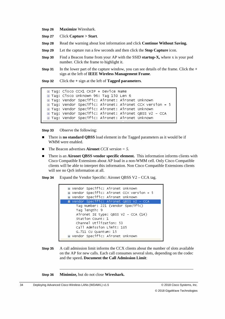
Step 33 Observe the following:
� There is no standard QBSS load element in the Tagged parameters as it would be if WMM were enabled.
� The Beacon advertises Aironet CCX version = 5.
� There is an Aironet QBSS vendor specific element. This information informs clients with Cisco Compatible Extensions about AP load in a non-WMM cell. Only Cisco Compatible clients will be able to interpret this information. Non Cisco Compatible Extensions clients will see no QoS information at all.
Step 34 Expand the Vendor Specific: Aironet QBSS V2 – CCA tag.
Step 35 A call admission limit informs the CCX clients about the number of slots available on the AP for new calls. Each call consumes several slots, depending on the codec and the speed. Document the Call Admission Limit: __________________________________________________________________
Step 36 Minimize, but do not close Wireshark.
© 2018 Cisco Systems, Inc. Remote Lab Guide 35
© 2018 GigaWave Technologies
Step 37 From the Systems menu, select Admin PC. The browser to the 2504 WLC should still be open.
Step 38 In the upper menu, click WLANs .
Step 39 Click the WLAN ID of the profile startup to edit its settings.
Step 40 Click the QoS tab.
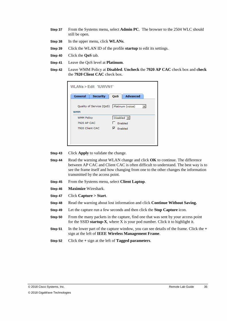
Step 41 Leave the QoS level at Platinum.
Step 42 Leave WMM Policy at Disabled. Uncheck the 7920 AP CAC check box and check the 7920 Client CAC check box.
Step 43 Click Apply to validate the change.
Step 44 Read the warning about WLAN change and click OK to continue. The difference between AP CAC and Client CAC is often difficult to understand. The best way is to see the frame itself and how changing from one to the other changes the information transmitted by the access point.
Step 45 From the Systems menu, select Client Laptop.
Step 46 Maximize Wireshark.
Step 47 Click Capture > Start.
Step 48 Read the warning about lost information and click Continue Without Saving.
Step 49 Let the capture run a few seconds and then click the Stop Capture icon.
Step 50 From the many packets in the capture, find one that was sent by your access point for the SSID startup-X , where X is your pod number. Click it to highlight it.
Step 51 In the lower part of the capture window, you can see details of the frame. Click the + sign at the left of IEEE Wireless Management Frame.
Step 52 Click the + sign at the left of Tagged parameters.
36 Deploying Advanced Cisco Wireless LANs (WDAWL) v1.5 © 2018 Cisco Systems, Inc.
© 2018 GigaWave Technologies
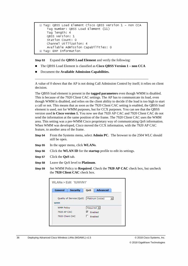
Step 53 Expand the QBSS Load Element and verify the following:
� The QBSS Load Element is classified as Cisco QBSS Version 1 – non CCA
� Document the Available Admission Capabilities.
___________________________________________________________________
A value of 0 shows that the AP is not doing Call Admission Control by itself; it relies on client decision.
The QBSS load element is present in the tagged parameters even though WMM is disabled. This is because of the 7920 Client CAC settings. The AP has to communicate its load, even though WMM is disabled, and relies on the client ability to decide if the load is too high to start a call or not. This means that as soon as the 7920 Client CAC setting is enabled, the QBSS load element is used, not for WMM purposes, but for CCX purposes. You can see that the QBSS version used is Cisco version 1. You now see that 7920 AP CAC and 7920 Client CAC do not send the information at the same position of the frame. The 7920 Client CAC uses the WMM area. This setting was a pre-WMM Cisco proprietary way of communicating QoS information. When WMM was developed, Cisco moved the CCX information, with the 7920 AP CAC feature, to another area of the frame.
Step 54 From the Systems menu, select Admin PC. The browser to the 2504 WLC should still be open.
Step 55 In the upper menu, click WLANs .
Step 56 Click the WLAN ID for the startup profile to edit its settings.
Step 57 Click the QoS tab.
Step 58 Leave the QoS level to Platinum.
Step 59 Set WMM Policy to Required. Check the 7920 AP CAC check box, but uncheck the 7920 Client CAC check box.
© 2018 Cisco Systems, Inc. Remote Lab Guide 37
© 2018 GigaWave Technologies
Step 60 Click Apply to validate the change.
Step 61 Read the warning about WLAN change and click OK to continue.
This time, WMM is required, which means that the WMM area of the beacons should be there. The 7920 AP CAC feature remains clicked, and it should be in the vendor specific area of the frame. Determine whether the AP will use WMM only, superseding the older 7920 AP CAC feature, or if it will communicate information about both to the clients.
Step 62 From the Systems menu, select Client Laptop. Wireshark should still be open.
Step 63 Click Capture > Start.
Step 64 Read the warning about lost information and click Continue Without Saving.
Step 65 Let the capture run a few seconds and then click the Stop Capture icon.
Step 66 Find a Beacon frame sent by your access point for the SSID startup-X, where X is your pod number. Click the frame to highlight it.
Step 67 In the lower part of the capture window, you can see details of the frame. Click the + sign at the left of IEEE Wireless Management Frame.
Step 68 Click the + sign at the left of Tagged parameters.
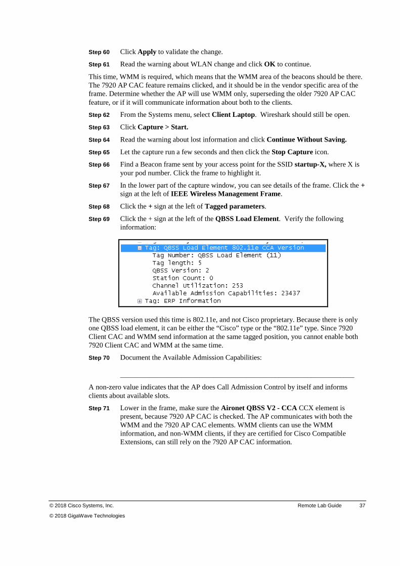
Step 69 Click the + sign at the left of the QBSS Load Element. Verify the following information:
The QBSS version used this time is 802.11e, and not Cisco proprietary. Because there is only one QBSS load element, it can be either the “Cisco” type or the “802.11e” type. Since 7920 Client CAC and WMM send information at the same tagged position, you cannot enable both 7920 Client CAC and WMM at the same time.
Step 70 Document the Available Admission Capabilities: _________________________________________________________________
A non-zero value indicates that the AP does Call Admission Control by itself and informs clients about available slots.
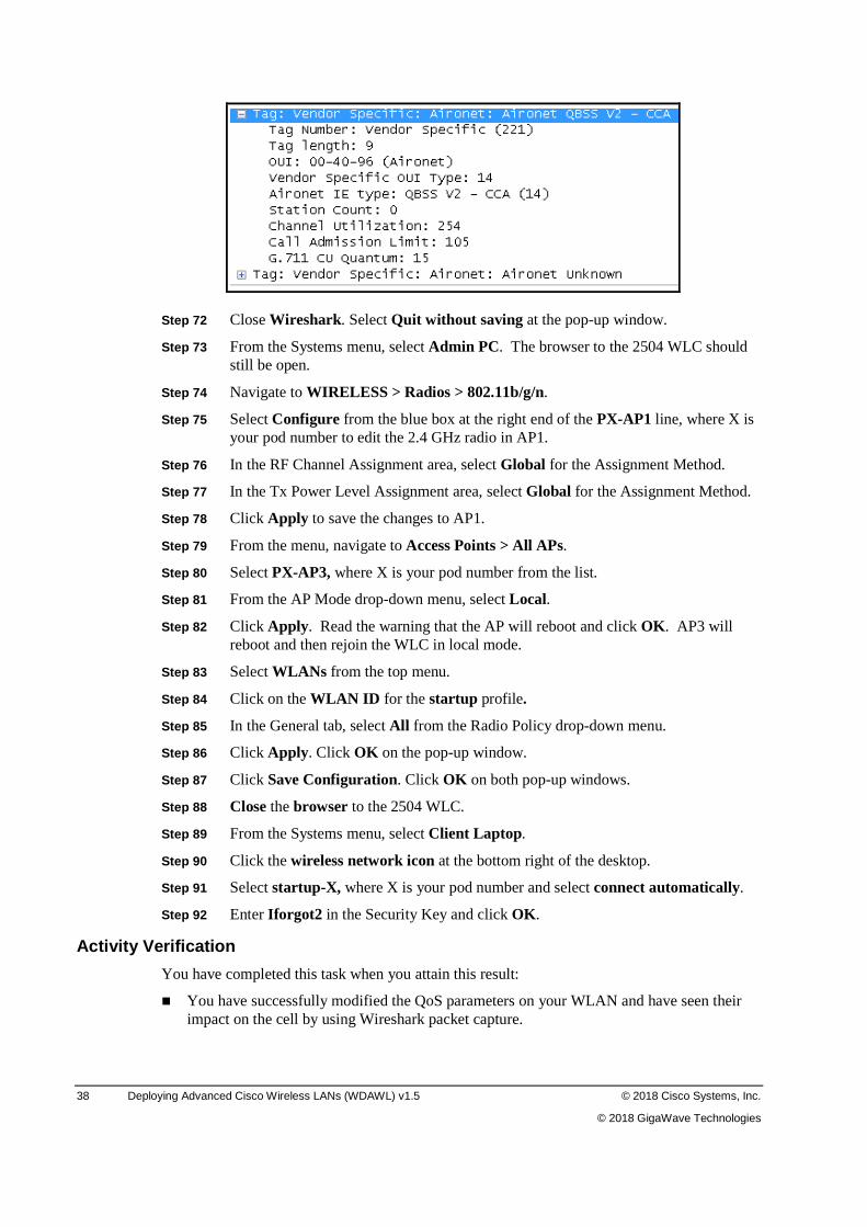
Step 71 Lower in the frame, make sure the Aironet QBSS V2 - CCA CCX element is present, because 7920 AP CAC is checked. The AP communicates with both the WMM and the 7920 AP CAC elements. WMM clients can use the WMM information, and non-WMM clients, if they are certified for Cisco Compatible Extensions, can still rely on the 7920 AP CAC information.
38 Deploying Advanced Cisco Wireless LANs (WDAWL) v1.5 © 2018 Cisco Systems, Inc.
© 2018 GigaWave Technologies
Step 72 Close Wireshark . Select Quit without saving at the pop-up window.
Step 73 From the Systems menu, select Admin PC. The browser to the 2504 WLC should still be open.
Step 74 Navigate to WIRELESS > Radios > 802.11b/g/n.
Step 75 Select Configure from the blue box at the right end of the PX-AP1 line, where X is your pod number to edit the 2.4 GHz radio in AP1.
Step 76 In the RF Channel Assignment area, select Global for the Assignment Method.
Step 77 In the Tx Power Level Assignment area, select Global for the Assignment Method.
Step 78 Click Apply to save the changes to AP1.
Step 79 From the menu, navigate to Access Points > All APs.
Step 80 Select PX-AP3, where X is your pod number from the list.
Step 81 From the AP Mode drop-down menu, select Local.
Step 82 Click Apply . Read the warning that the AP will reboot and click OK . AP3 will reboot and then rejoin the WLC in local mode.
Step 83 Select WLANs from the top menu.
Step 84 Click on the WLAN ID for the startup profile.
Step 85 In the General tab, select All from the Radio Policy drop-down menu.
Step 86 Click Apply . Click OK on the pop-up window.
Step 87 Click Save Configuration. Click OK on both pop-up windows.
Step 88 Close the browser to the 2504 WLC.
Step 89 From the Systems menu, select Client Laptop.
Step 90 Click the wireless network icon at the bottom right of the desktop.
Step 91 Select startup-X, where X is your pod number and select connect automatically.
Step 92 Enter Iforgot2 in the Security Key and click OK .
Activity Verification
You have completed this task when you attain this result:
� You have successfully modified the QoS parameters on your WLAN and have seen their impact on the cell by using Wireshark packet capture.
© 2018 Cisco Systems, Inc. Remote Lab Guide 39
© 2018 GigaWave Technologies
Task 3: Closing the Lab In this task, you will close the lab session.
Note If you are continuing to the next Hardware Challenge Lab at this time, skip this task and
continue to the next lab.
Step 1 Select Diagram from the Systems menu.
Step 2 In the upper-right corner, click the X to close the Lab Topology Diagram.
40 Deploying Advanced Cisco Wireless LANs (WDAWL) v1.5 © 2018 Cisco Systems, Inc.
© 2018 GigaWave Technologies
Lab 2-1: Configuring IPv6 Complete this lab activity to practice what you learned in the related module.
Activity Objective
In this activity, you will configure IPv6 on your WLC. You will achieve these objectives:
� Configure IPv6 on the WLC
� Test connectivity to your WLC using ping and a web browser
Required Resources
These are the resources and equipment required to complete this activity:
� For each group of students (student pod), a laptop which can be used to create an RDP session to the assigned Pod laptop
All cabling required has been performed by the instructor.
Note Critical success path: Follow the step-by-step procedure given in this lab.
Task 1: Configure IPv6 on your Switch and WLC In this task, you will set up IPv6 on the WLC.
Activity Procedure
Complete the following steps:
If you are continuing from the previous lab, skip to Step 2.
Step 1 From your PC, open a web browser session to the GigaWave remote labs at the address http://giga-wave.remotelabs.com
Step 2 From the Diagram page, select the icon for the PodX-3650sw. The Pod-Sw page opens.
Step 3 To activate the console CLI, click in the console area and press Enter.
Step 4 Login to the switch using the following values:
� Username: admin
� Password: Iforgot2
Step 5 Enter the following commands to activate IPv6 routing on the 3650 switch, where X is your pod number.
PodX-3650sw#configure terminal
PodX-3650sw(config)#interface vlan 1X (ex.VLAN1=11 VLAN10=110)
PodX-3650sw(config-if)#ipv6 address 2001:X:X:X10::20/64
Note Example addresses
Pod 1 = 2001:1:1:110::20/64 Pod 7 = 2001:7:7:710::20/64
Pod 10 = 2001:10:10:1010::20/64 Pod 35 = 2001:35:35:3510::20/64
PodX-3650sw(config-if)#exit
PodX-3650sw(config)ipv6 unicast-routing
PodX-3650sw(config)end
© 2018 Cisco Systems, Inc. Remote Lab Guide 41
© 2018 GigaWave Technologies
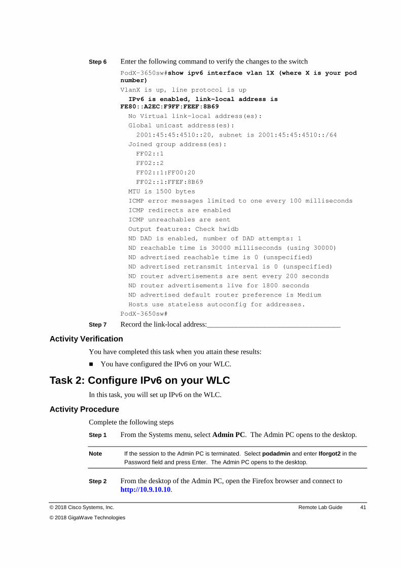
Step 6 Enter the following command to verify the changes to the switch
PodX-3650sw#show ipv6 interface vlan 1X (where X is your pod number)
VlanX is up, line protocol is up
IPv6 is enabled, link-local address is FE80::A2EC:F9FF:FEEF:8B69
No Virtual link-local address(es):
Global unicast address(es):
2001:45:45:4510::20, subnet is 2001:45:45:4510::/64
Joined group address(es):
FF02::1
FF02::2
FF02::1:FF00:20
FF02::1:FFEF:8B69
MTU is 1500 bytes
ICMP error messages limited to one every 100 milliseconds
ICMP redirects are enabled
ICMP unreachables are sent
Output features: Check hwidb
ND DAD is enabled, number of DAD attempts: 1
ND reachable time is 30000 milliseconds (using 30000)
ND advertised reachable time is 0 (unspecified)
ND advertised retransmit interval is 0 (unspecified)
ND router advertisements are sent every 200 seconds
ND router advertisements live for 1800 seconds
ND advertised default router preference is Medium
Hosts use stateless autoconfig for addresses.
PodX-3650sw#
Step 7 Record the link-local address:_____________________________________
Activity Verification
You have completed this task when you attain these results:
� You have configured the IPv6 on your WLC.
Task 2: Configure IPv6 on your WLC In this task, you will set up IPv6 on the WLC.
Activity Procedure
Complete the following steps
Step 1 From the Systems menu, select Admin PC. The Admin PC opens to the desktop.
Note If the session to the Admin PC is terminated. Select podadmin and enter Iforgot2 in the
Password field and press Enter. The Admin PC opens to the desktop.
Step 2 From the desktop of the Admin PC, open the Firefox browser and connect to http://10.9.10.10.
42 Deploying Advanced Cisco Wireless LANs (WDAWL) v1.5 © 2018 Cisco Systems, Inc.
© 2018 GigaWave Technologies
Step 3 Click Login.
Step 4 Login with the following values:
� User Name: admin
� Password: Iforgot2
Step 5 Select CONTROLLER from the top menu.
Step 6 In the left menu, select Interfaces. The interfaces page opens.
Step 7 Select the Interface Name of management. The Interfaces > Edit page opens.
Step 8 In the Interface Address area, enter 2001:X:X:X10::10 format, where X is your pod number in the IPv6 Address field. This is the Primary IPv6 Address number.
Step 9 In the Prefix Length field, enter 64.
Step 10 In the IPv6 Gateway field, enter the link-local address of the gateway you recorded in the previous task.
Step 11 Click Apply to save the settings.
Step 12 Click OK on both warning popups window.
Activity Verification
You have completed this task when you attain these results:
� You have configured the IPv6 on your WLC.
Task 3: Verify IPv6 on your Client Laptop and Test IPv6 Connectivity
In this task, you will check the IPv6 configuration on the client laptop and test IPv6 connectivity.
Activity Procedure
Complete the following steps:
Step 1 From the Systems menu, select Client Laptop.
Step 2 Login to the student account using password in the Password field.
Step 3 Click the network icon in the lower right of the window and connect to startup-X, where X is your pod number.
Step 4 Open a windows command prompt window.
Step 5 Type ipconfig. Record the IPv6 Address for your Wireless LAN adapter Intel 4965 Wireless: interface _____________________________________________
Step 6 From the cmd prompt, enter ping 2001:X:X:X10::20, where X is your pod number.
Step 7 Open a browser window and connect to http://[2001: X:X:X10::10] (where X is your pod number). You must include the lower case brackets.
Note Be sure to include the brackets on the IPv6 address in the browser. HTTP and HTTPS
require brackets[ ] around the IPv6 address. For example [2001:45:45:4510::10]
Step 8 Click Login to log in to the controller using admin / Iforgot2 as your credentials. The Monitor page of the controller appears.
© 2018 Cisco Systems, Inc. Remote Lab Guide 43
© 2018 GigaWave Technologies
Step 9 From your Client Laptop, open a cmd prompt window, ping the controller using the command ping 2001: X:X:X10::10.
Activity Verification
You have completed this task when you attain these results:
� You have successfully confirmed IPv6 addressing on your class laptop.
� You have successfully pinged, and connected to your WLC using a web browser and IPv6.
Task 4: Closing the Lab In this task, you will close the lab session.
Note If you are continuing to the next Hardware Challenge Lab at this time, skip this task and
continue to the next lab.
Step 1 Select Diagram from the Systems menu.
Step 2 In the upper-right corner, click the X to close the Lab Topology Diagram.
44 Deploying Advanced Cisco Wireless LANs (WDAWL) v1.5 © 2018 Cisco Systems, Inc.
© 2018 GigaWave Technologies
Lab 2-2: IPv6 First Hop Security Configuration (Optional)
Complete this lab activity to practice what you learned in the related module.
Activity Objective
This lab looks at the controller web interface capabilities to configure IPv6 support for your wireless clients in the most optimal and secure manner.
Required Resources
These are the resources and equipment required to complete this activity:
� For each group of students (student pod), a laptop which can be used to create an RDP session to the assigned Pod laptop
� A designated wireless LAN controller for the group
� An AP with connectivity to the classroom lab Ethernet switch
� WLAN controller connectivity to the classroom lab Ethernet switch
All cabling required has been performed by the instructor.
Note Critical success path: Follow the step-by-step procedure given in this lab.
Task 1: Configure IPv6 Support Activity Procedure
Complete the following steps:
If you are continuing from the previous lab, skip to Step 2.
Step 1 From your PC, open a web browser session to the GigaWave remote labs at the address http://giga-wave.remotelabs.com
Step 2 From the Systems menu, select Admin PC.
Step 3 From the desktop of your Admin PC, open a web browser to https://10.9.10.10
Step 4 Click Login.
Step 5 Sign in with the following credentials:
Username Password
admin Iforgot2
Step 6 From the top menu, select WLANs .
Step 7 Click WLAN ID 1 (Profile Name startup). The WLANs > Edit startup page opens.
Step 8 Select the Security tab. The Layer 2 sub tab displays.
Step 9 Confirm that the PSK Enable check box in the Authentication Key Management area is checked.
Step 10 Confirm that the PSK Format drop-down menu is set to ASCII .
© 2018 Cisco Systems, Inc. Remote Lab Guide 45
© 2018 GigaWave Technologies
Step 11 In the PSK field ,enter Iforgot2 .
Step 12 Click Apply to save the changes.
Step 13 Click OK in the pop-up window.
Step 14 Select CONTROLLER from the top menu bar.
Step 15 Expand the IPv6 options on the left side of the window.
Step 16 Select Neighbor Binding and answer the following questions. (Hint remember the HELP menu is available)
Q1) What is the default setting for the Down Lifetime?_____________________________
Q2) What does this timer represent? ____________________________________________
Q3) What is the default setting for the Reachable Lifetime?__________________________
Q4) What does this timer represent? ______________________________________________________________________
Q5) What is the default setting for the Stale Lifetime?______________________________
Q6) What does this timer represent? _____________________________________________________________________
Step 17 Select RAThrottle Policy from the options on the left side of the window.
Q7) What is the purpose of the RA Throttle Policy?________________________________
Step 18 Enable the RA Throttle Policy on the controller by checking the check box.
Step 19 Set the Throttle Period to 180.
Q8) What does this setting represent?___________________________________________
Step 20 Change the Max Through to 5
Q9) What does this setting represent?___________________________________________
Step 21 Click on Apply to commit your changes.
Now you will enable the Client Laptop to be an IPv6 router to test the IPv6 RA Guard function on the controller.
Step 22 From the Systems menu, select Client Laptop.
Step 23 Click on the start icon to display the Windows start menu.
Step 24 Type cmd in the blank field to display the cmd program.
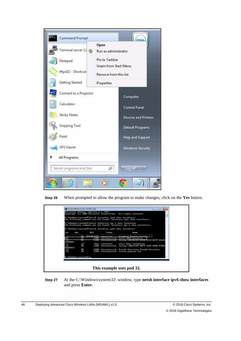
Step 25 Right-click on the Command Prompt icon at the top of the Start menu and select Run as administrator.
46 Deploying Advanced Cisco Wireless LANs (WDAWL) v1.5 © 2018 Cisco Systems, Inc.
© 2018 GigaWave Technologies
Step 26 When prompted to allow the program to make changes, click on the Yes button.
This example uses pod 32.
Step 27 At the C:\Windows\system32\ window, type netsh interface ipv6 show interfaces and press Enter.
© 2018 Cisco Systems, Inc. Remote Lab Guide 47
© 2018 GigaWave Technologies
Step 28 Examine the resulting display and locate the index number your Intel 4765 Wireless Network Connection and record it here __________________________________________________________________.
Step 29 At the windows command prompt,
type netsh interface ipv6 set int ## advertise=enable managed=enable
(where ## is the index number you recorded in the last step) and press Enter.
Step 30 From the Client Laptop, click on the network icon to display the available wireless networks.
Step 31 Locate startup-x, where X is your pod number, click on it and select Connect.
Step 32 If prompted, enter Iforgot2 in the Security key field and then click OK.
Step 33 Maximize your browser session to the controller.
Step 34 Select the CONTROLLER link at the top of the window.
Step 35 Expand the IPv6 options on the left of the window and then click on the RA Guard link.
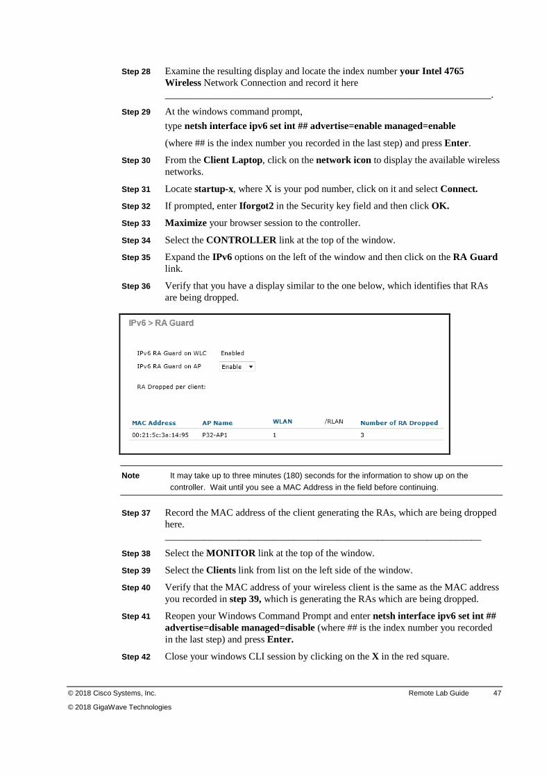
Step 36 Verify that you have a display similar to the one below, which identifies that RAs are being dropped.
Note It may take up to three minutes (180) seconds for the information to show up on the
controller. Wait until you see a MAC Address in the field before continuing.
Step 37 Record the MAC address of the client generating the RAs, which are being dropped here. ________________________________________________________________
Step 38 Select the MONITOR link at the top of the window.
Step 39 Select the Clients link from list on the left side of the window.
Step 40 Verify that the MAC address of your wireless client is the same as the MAC address you recorded in step 39, which is generating the RAs which are being dropped.
Step 41 Reopen your Windows Command Prompt and enter netsh interface ipv6 set int ## advertise=disable managed=disable (where ## is the index number you recorded in the last step) and press Enter.
Step 42 Close your windows CLI session by clicking on the X in the red square.
48 Deploying Advanced Cisco Wireless LANs (WDAWL) v1.5 © 2018 Cisco Systems, Inc.
© 2018 GigaWave Technologies
Activity Verification
You have completed this task when you attain these results:
� You have configured the RA throttle policy and verified that that the number of Router Advertisements generated on the wired side and delivered via Wireless are being reduced.
� You have verified that any RAs being generated by wireless clients are being dropped.
Task 2: Closing the Lab In this task, you will close the lab session.
Note If you are continuing to the next Hardware Challenge Lab at this time, skip this task and
continue to the next lab.
Step 1 Select Diagram from the Systems menu.
Step 2 In the upper-right corner, click the X to close the Lab Topology Diagram.