Embed Size (px)
Citation preview

Depleted Argon from Underground SourcesHenning O. Back – Princeton UniversityFor the DarkSide experiment, E-1000
Augustana College – D. AltonFNAL – C. Kendziora, D. Montanari, S. PordesPrinceton U. – F. Calaprice, C. Galbiati, A. Goretti, Andrea Ianni, B. Loer, P. Mosteiro

TIPP 2011 2
Why depleted argon
• Naturally occurring 39Ar is the limiting contamination in atmospheric argon– 39Ar 39K + e- +`νe (Q = 535 keV)– Limits size of detectors due to pile up
• Atmospheric 39Ar is produced in the upper atmosphere in 40Ar(n, 2n) reactions
• Atmospheric concentration 39Ar/40Ar = 8.1×10⁻¹⁶
– Corresponds to 1 Bq/kg of atmospheric argon– One ton detector
• Electron drift time across 1 ton detector (1m)= order 500μs (minimum time between events, equivalent to 2kHz)
• Atmospheric 39Ar decay rate = 1kHz/ton
6/10/2011
TIPP 2011 3
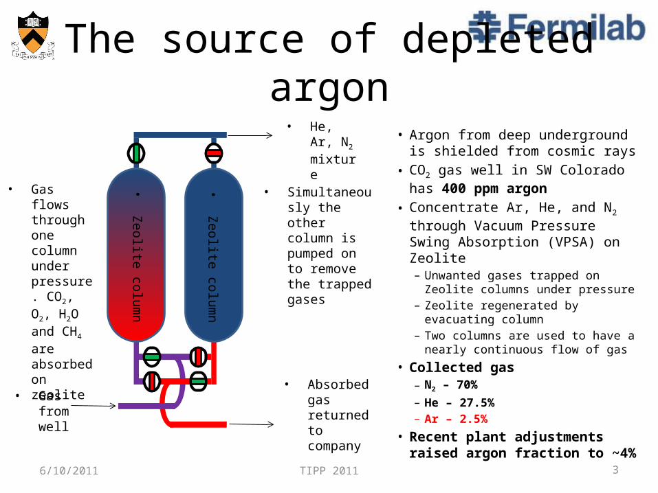
The source of depleted argon
• Argon from deep underground is shielded from cosmic rays
• CO2 gas well in SW Colorado has 400 ppm argon
• Concentrate Ar, He, and N2 through Vacuum Pressure Swing Absorption (VPSA) on Zeolite– Unwanted gases trapped on Zeolite
columns under pressure– Zeolite regenerated by evacuating
column – Two columns are used to have a
nearly continuous flow of gas
• Collected gas– N2 – 70%– He – 27.5%– Ar – 2.5%
• Recent plant adjustments raised argon fraction to ~4%6/10/2011
• He, Ar, N2 mixture
• Gas from well
• Absorbed gas returned to company
•Zeolite colum
n
•Zeolite colum
n
• Gas flows through one column under pressure. CO2, O2, H2O and CH4 are absorbed on zeolite
• Simultaneously the other column is pumped on to remove the trapped gases
TIPP 2011 4
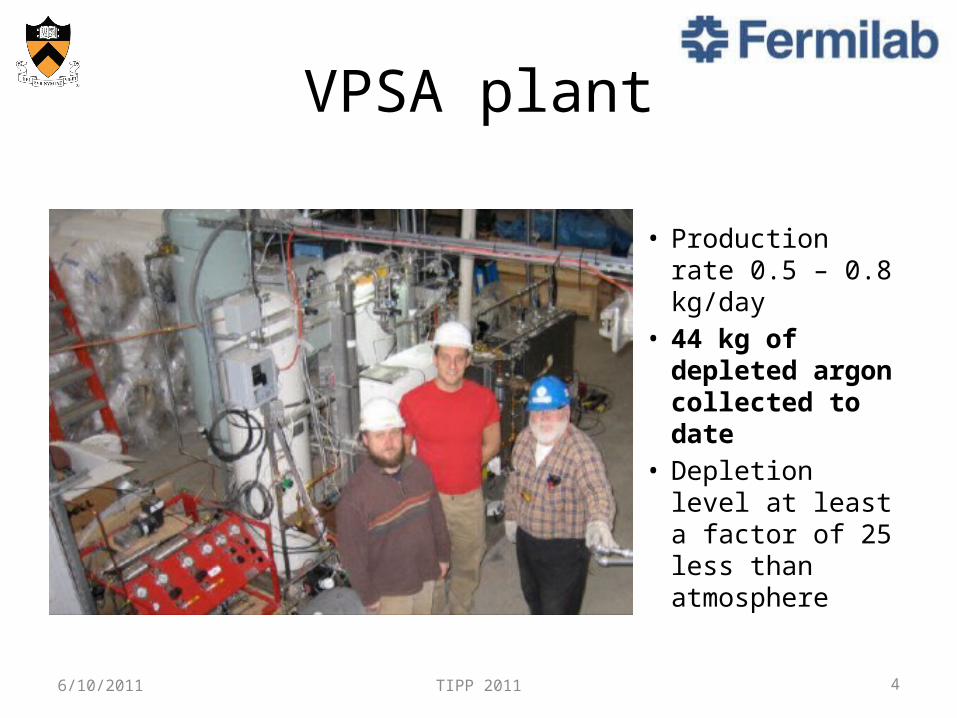
VPSA plant
• Production rate 0.5 – 0.8 kg/day
• 44 kg of depleted argon collected to date
• Depletion level at least a factor of 25 less than atmosphere
6/10/2011

TIPP 2011 5
Argon from VPSA is born underground
6/10/2011
• Terrestrial 40Ar primarily from 40K decay• 36Ar produced in the
sun and has an atmospheric natural abundance of 0.35%

TIPP 2011 6
Cryogenic DistillationPurification of gas from VPSA plant
• Purification by distillation based on difference in boiling points
• Boiling happens on the surface of column packing material
• Our gas has helium, which is not liquefied and just passes through system
6/10/2011
Inject liquefied Ar/N2into column
Waste gas (He and N2)
Product (pure Argon)
Lower boiling point gas preferentially moves up column
Higher boiling point liquid preferentially moves down column
Packed column
Temperature gradient
5.5 cm
Column packing material

TIPP 2011 7
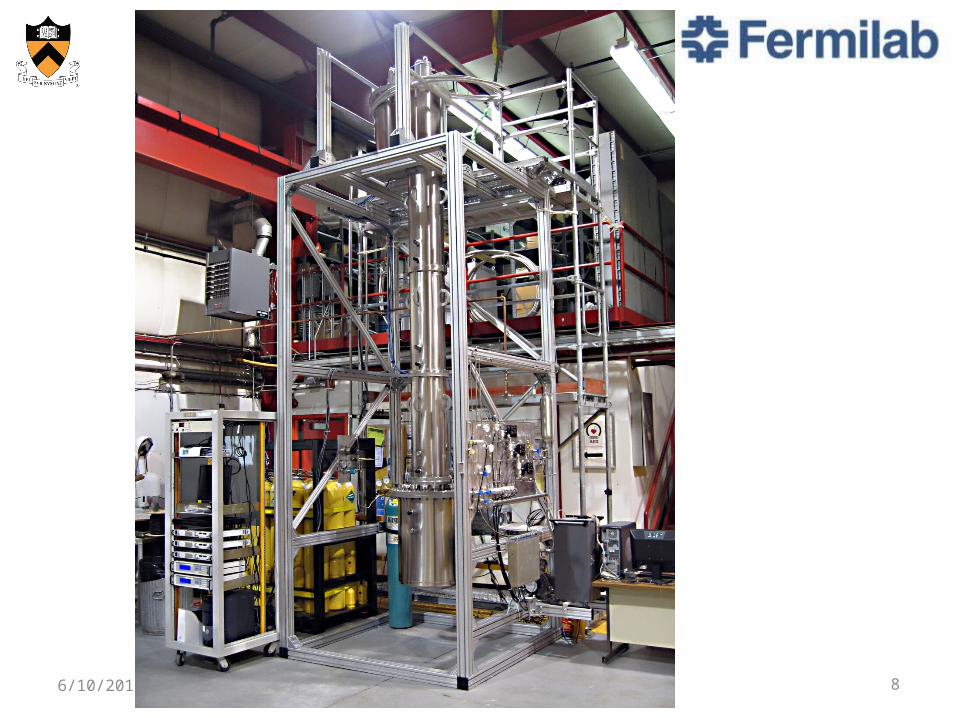
Our design• 2 – 600W cryocoolers
– Balanced with 700W heaters for temperature control
• Reboiler cooled by liquid from column– Temperature controlled with 700W
heater
• Active PID temperature control • Active mass flow control• Pressure and temperature monitoring
throughout• Multiple input RGA measures gas at
three points– Input– Waste– Product
6/10/2011
TIPP 2011 86/10/2011

TIPP 2011 9
Control system
6/10/2011
UGA

TIPP 2011 10
Commissioning• Pre-safety review
– Verify temperature control while under vacuum– Verify mass flow control– Measure gas composition of gas from Colorado
• Found concentration to be: Ar – 2.5%, He - 27.5%, and N2 – 70%
• Post safety review– Temperature control with gas load
• Controls temperature to within 0.5K
– Column cool down (Ar and N2)• Column can be cooled in ~5 hours
– Full commissioning run (Goals)• Use same gas mixture as Colorado gas (N2 = 70%, He = 27.5%, Ar = 2.5%)• Show that Distillation Column can condense all Ar, even at low concentrations• Show continuous distillation is possible• Show that batch distillation works
6/10/2011

TIPP 2011 11
Argon condensation• 5 hours after
start up, we are condensing all the argon!
6/10/2011
Input(Ar, N2. He)
Waste gas (He and N2)
Product

TIPP 2011 12
First continuous distillationHelium is not liquefied; it just passes through the systemNormalizing to Helium allows a direct comparison of input and waste gases
Input gas• N2/He ~ 4.23• Ar/He ~ 0.22Waste gas• N2/He ~ 4.43• Ar/He ~ 0.02Conclusion• More argon is entering
than leaving (~90% is being collected)
• More N2 is leaving than entering
• First continuous distillation!6/10/2011
TIPP 2011 13
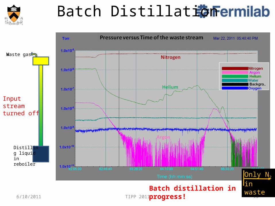
Batch Distillation
6/10/2011
Input streamturned off
Batch distillation in progress!
Waste gas
Distilling liquid in reboiler
Only N2
in waste

TIPP 2011 14
Batch Distillation
6/10/2011
Product line shows concentration of Ar and N2 in reboiler.
Input
Waste gas
Product
P = product lineW = waste line
N2 concentration in reboiler is dropping throughout distillation run – Batch distillation works!
Start – Ar:N2 = 1:30Stop – Ar:N2 = 33:1
~ Factor 1000 reduction
TIPP 2011 15
Conclusions and Future
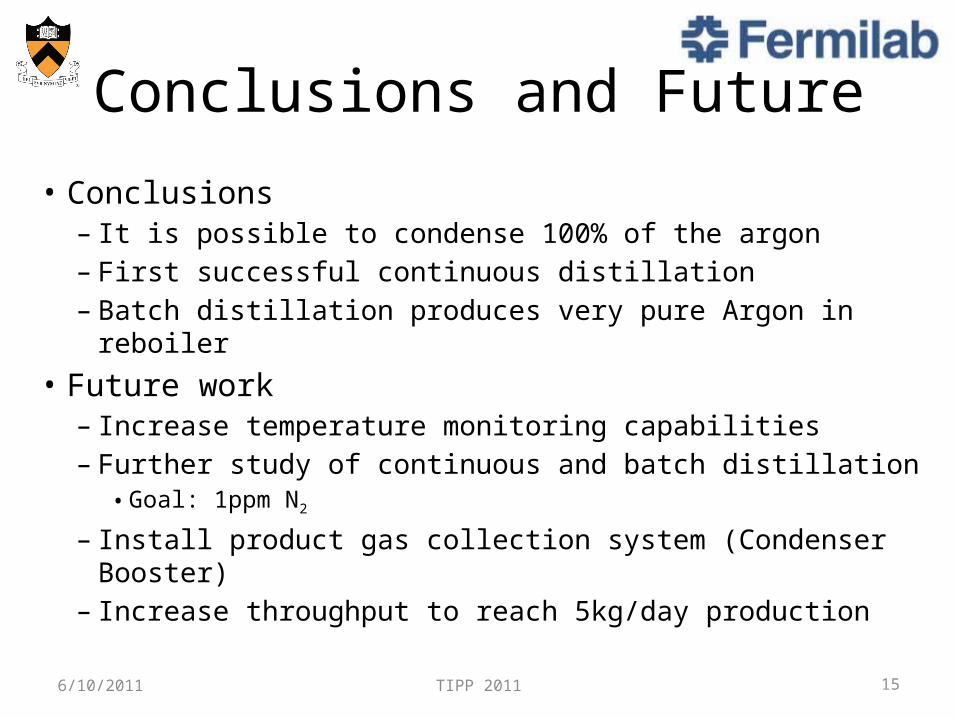
• Conclusions– It is possible to condense 100% of the argon– First successful continuous distillation– Batch distillation produces very pure Argon in reboiler
• Future work– Increase temperature monitoring capabilities– Further study of continuous and batch distillation
• Goal: 1ppm N2
– Install product gas collection system (Condenser Booster)– Increase throughput to reach 5kg/day production
6/10/2011