Embed Size (px)
Citation preview
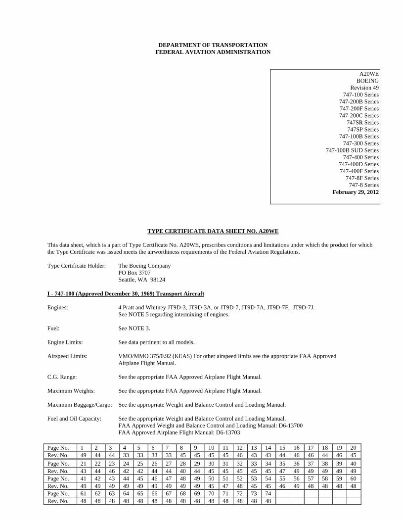
Page No. 1 2 3 4 5 6 7 8 9 10 11 12 13 14 15 16 17 18 19 20 Rev. No. 49 44 44 33 33 33 33 45 45 45 45 46 43 43 44 46 46 44 46 45
Page No. 21 22 23 24 25 26 27 28 29 30 31 32 33 34 35 36 37 38 39 40 Rev. No. 43 44 46 42 42 44 44 40 44 45 45 45 45 45 47 49 49 49 49 49 Page No. 41 42 43 44 45 46 47 48 49 50 51 52 53 54 55 56 57 58 59 60 Rev. No. 49 49 49 49 49 49 49 49 49 45 47 48 45 45 46 49 48 48 48 48 Page No. 61 62 63 64 65 66 67 68 69 70 71 72 73 74 Rev. No. 48 48 48 48 48 48 48 48 48 48 48 48 48 48
DEPARTMENT OF TRANSPORTATION FEDERAL AVIATION ADMINISTRATION
A20WE BOEING
Revision 49 747-100 Series
747-200B Series 747-200F Series 747-200C Series
747SR Series 747SP Series
747-100B Series 747-300 Series
747-100B SUD Series 747-400 Series
747-400D Series 747-400F Series
747-8F Series 747-8 Series
February 29, 2012
TYPE CERTIFICATE DATA SHEET NO. A20WE This data sheet, which is a part of Type Certificate No. A20WE, prescribes conditions and limitations under which the product for which the Type Certificate was issued meets the airworthiness requirements of the Federal Aviation Regulations. Type Certificate Holder: The Boeing Company PO Box 3707 Seattle, WA 98124 I - 747-100 (Approved December 30, 1969) Transport Aircraft Engines: 4 Pratt and Whitney JT9D-3, JT9D-3A, or JT9D-7, JT9D-7A, JT9D-7F, JT9D-7J. See NOTE 5 regarding intermixing of engines. Fuel: See NOTE 3. Engine Limits: See data pertinent to all models. Airspeed Limits: VMO/MMO 375/0.92 (KEAS) For other airspeed limits see the appropriate FAA Approved Airplane Flight Manual. C.G. Range: See the appropriate FAA Approved Airplane Flight Manual. Maximum Weights: See the appropriate FAA Approved Airplane Flight Manual. Maximum Baggage/Cargo: See the appropriate Weight and Balance Control and Loading Manual. Fuel and Oil Capacity: See the appropriate Weight and Balance Control and Loading Manual. FAA Approved Weight and Balance Control and Loading Manual: D6-13700 FAA Approved Airplane Flight Manual: D6-13703
A20WE 2
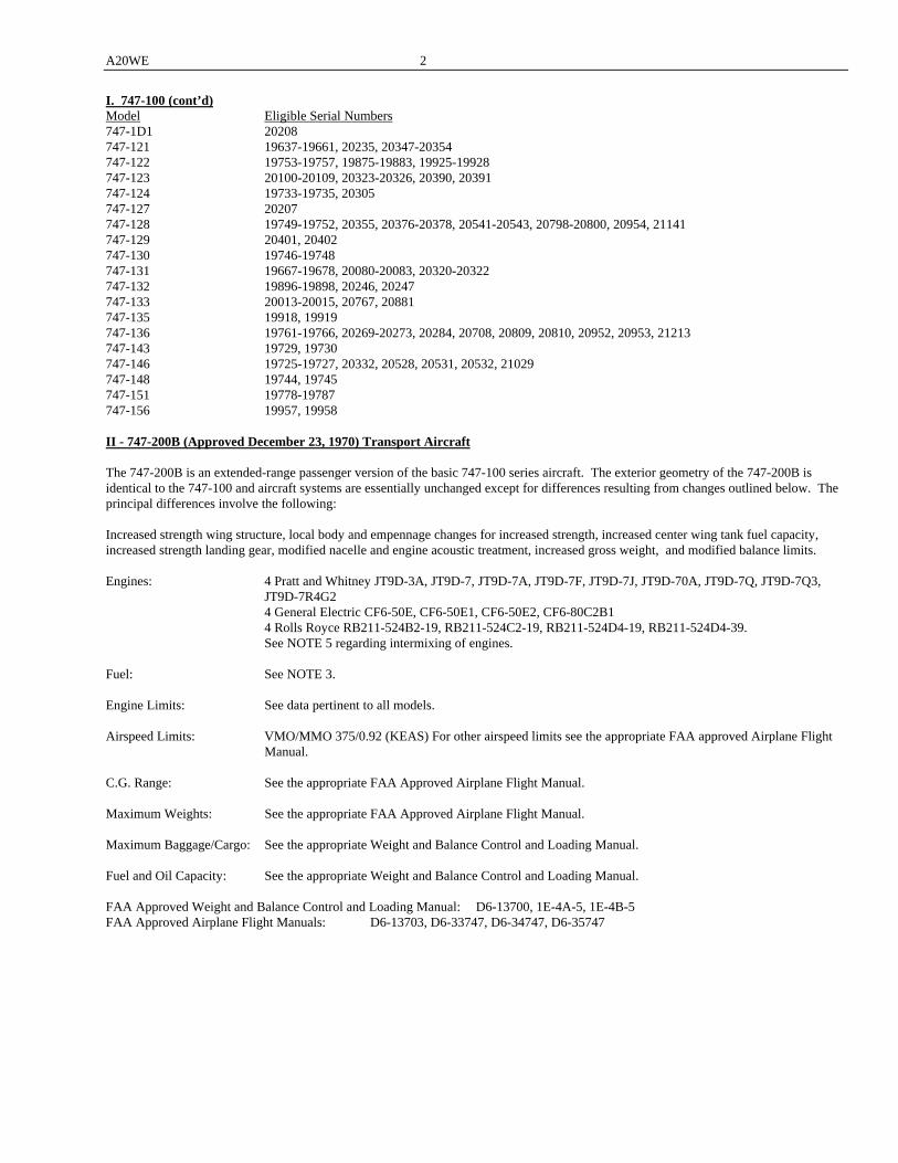
I. 747-100 (cont’d) Model Eligible Serial Numbers 747-1D1 20208 747-121 19637-19661, 20235, 20347-20354 747-122 19753-19757, 19875-19883, 19925-19928 747-123 20100-20109, 20323-20326, 20390, 20391 747-124 19733-19735, 20305 747-127 20207 747-128 19749-19752, 20355, 20376-20378, 20541-20543, 20798-20800, 20954, 21141 747-129 20401, 20402 747-130 19746-19748 747-131 19667-19678, 20080-20083, 20320-20322 747-132 19896-19898, 20246, 20247 747-133 20013-20015, 20767, 20881 747-135 19918, 19919 747-136 19761-19766, 20269-20273, 20284, 20708, 20809, 20810, 20952, 20953, 21213 747-143 19729, 19730 747-146 19725-19727, 20332, 20528, 20531, 20532, 21029 747-148 19744, 19745 747-151 19778-19787 747-156 19957, 19958 II - 747-200B (Approved December 23, 1970) Transport Aircraft The 747-200B is an extended-range passenger version of the basic 747-100 series aircraft. The exterior geometry of the 747-200B is identical to the 747-100 and aircraft systems are essentially unchanged except for differences resulting from changes outlined below. The principal differences involve the following: Increased strength wing structure, local body and empennage changes for increased strength, increased center wing tank fuel capacity, increased strength landing gear, modified nacelle and engine acoustic treatment, increased gross weight, and modified balance limits. Engines: 4 Pratt and Whitney JT9D-3A, JT9D-7, JT9D-7A, JT9D-7F, JT9D-7J, JT9D-70A, JT9D-7Q, JT9D-7Q3,
JT9D-7R4G2 4 General Electric CF6-50E, CF6-50E1, CF6-50E2, CF6-80C2B1 4 Rolls Royce RB211-524B2-19, RB211-524C2-19, RB211-524D4-19, RB211-524D4-39. See NOTE 5 regarding intermixing of engines. Fuel: See NOTE 3. Engine Limits: See data pertinent to all models. Airspeed Limits: VMO/MMO 375/0.92 (KEAS) For other airspeed limits see the appropriate FAA approved Airplane Flight
Manual. C.G. Range: See the appropriate FAA Approved Airplane Flight Manual. Maximum Weights: See the appropriate FAA Approved Airplane Flight Manual. Maximum Baggage/Cargo: See the appropriate Weight and Balance Control and Loading Manual. Fuel and Oil Capacity: See the appropriate Weight and Balance Control and Loading Manual. FAA Approved Weight and Balance Control and Loading Manual: D6-13700, 1E-4A-5, 1E-4B-5 FAA Approved Airplane Flight Manuals: D6-13703, D6-33747, D6-34747, D6-35747
3 A20WE
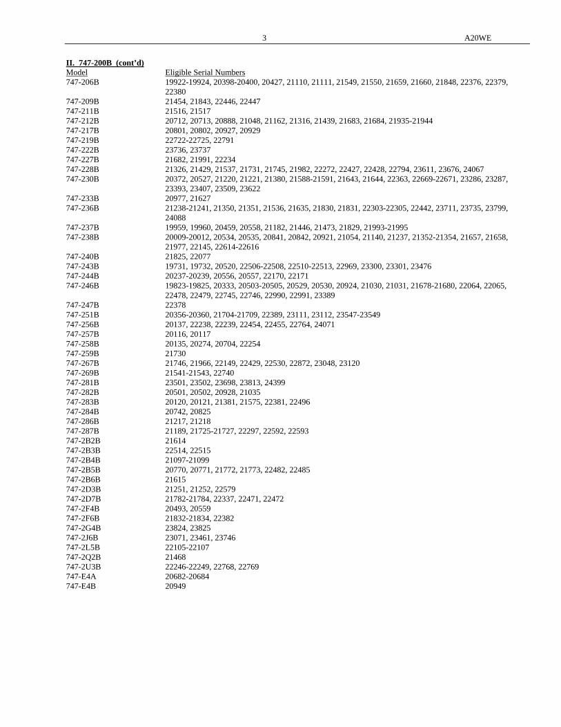
II. 747-200B (cont’d) Model Eligible Serial Numbers 747-206B 19922-19924, 20398-20400, 20427, 21110, 21111, 21549, 21550, 21659, 21660, 21848, 22376, 22379,
22380 747-209B 21454, 21843, 22446, 22447 747-211B 21516, 21517 747-212B 20712, 20713, 20888, 21048, 21162, 21316, 21439, 21683, 21684, 21935-21944 747-217B 20801, 20802, 20927, 20929 747-219B 22722-22725, 22791 747-222B 23736, 23737 747-227B 21682, 21991, 22234 747-228B 21326, 21429, 21537, 21731, 21745, 21982, 22272, 22427, 22428, 22794, 23611, 23676, 24067 747-230B 20372, 20527, 21220, 21221, 21380, 21588-21591, 21643, 21644, 22363, 22669-22671, 23286, 23287,
23393, 23407, 23509, 23622 747-233B 20977, 21627 747-236B 21238-21241, 21350, 21351, 21536, 21635, 21830, 21831, 22303-22305, 22442, 23711, 23735, 23799,
24088 747-237B 19959, 19960, 20459, 20558, 21182, 21446, 21473, 21829, 21993-21995 747-238B 20009-20012, 20534, 20535, 20841, 20842, 20921, 21054, 21140, 21237, 21352-21354, 21657, 21658,
21977, 22145, 22614-22616 747-240B 21825, 22077 747-243B 19731, 19732, 20520, 22506-22508, 22510-22513, 22969, 23300, 23301, 23476 747-244B 20237-20239, 20556, 20557, 22170, 22171 747-246B 19823-19825, 20333, 20503-20505, 20529, 20530, 20924, 21030, 21031, 21678-21680, 22064, 22065,
22478, 22479, 22745, 22746, 22990, 22991, 23389 747-247B 22378 747-251B 20356-20360, 21704-21709, 22389, 23111, 23112, 23547-23549 747-256B 20137, 22238, 22239, 22454, 22455, 22764, 24071 747-257B 20116, 20117 747-258B 20135, 20274, 20704, 22254 747-259B 21730 747-267B 21746, 21966, 22149, 22429, 22530, 22872, 23048, 23120 747-269B 21541-21543, 22740 747-281B 23501, 23502, 23698, 23813, 24399 747-282B 20501, 20502, 20928, 21035 747-283B 20120, 20121, 21381, 21575, 22381, 22496 747-284B 20742, 20825 747-286B 21217, 21218 747-287B 21189, 21725-21727, 22297, 22592, 22593 747-2B2B 21614 747-2B3B 22514, 22515 747-2B4B 21097-21099 747-2B5B 20770, 20771, 21772, 21773, 22482, 22485 747-2B6B 21615 747-2D3B 21251, 21252, 22579 747-2D7B 21782-21784, 22337, 22471, 22472 747-2F4B 20493, 20559 747-2F6B 21832-21834, 22382 747-2G4B 23824, 23825 747-2J6B 23071, 23461, 23746 747-2L5B 22105-22107 747-2Q2B 21468 747-2U3B 22246-22249, 22768, 22769 747-E4A 20682-20684 747-E4B 20949
A20WE 4
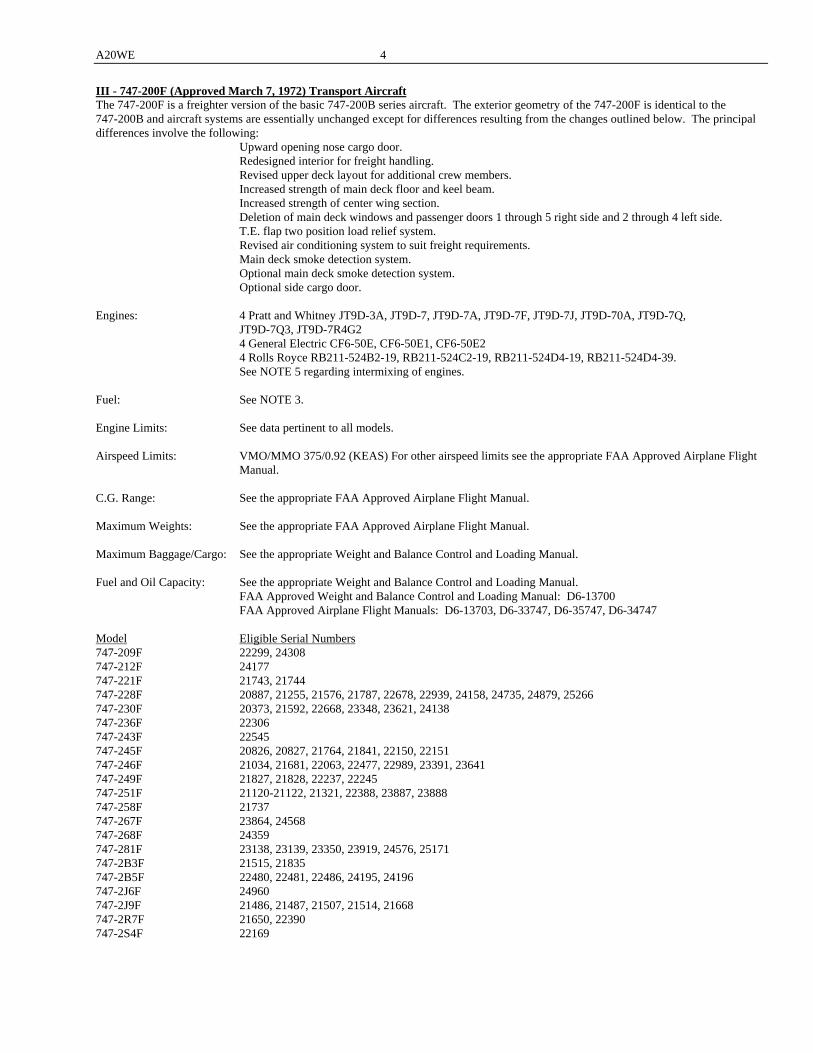
III - 747-200F (Approved March 7, 1972) Transport Aircraft The 747-200F is a freighter version of the basic 747-200B series aircraft. The exterior geometry of the 747-200F is identical to the 747-200B and aircraft systems are essentially unchanged except for differences resulting from the changes outlined below. The principal differences involve the following: Upward opening nose cargo door. Redesigned interior for freight handling. Revised upper deck layout for additional crew members. Increased strength of main deck floor and keel beam. Increased strength of center wing section. Deletion of main deck windows and passenger doors 1 through 5 right side and 2 through 4 left side. T.E. flap two position load relief system. Revised air conditioning system to suit freight requirements. Main deck smoke detection system. Optional main deck smoke detection system. Optional side cargo door. Engines: 4 Pratt and Whitney JT9D-3A, JT9D-7, JT9D-7A, JT9D-7F, JT9D-7J, JT9D-70A, JT9D-7Q,
JT9D-7Q3, JT9D-7R4G2 4 General Electric CF6-50E, CF6-50E1, CF6-50E2 4 Rolls Royce RB211-524B2-19, RB211-524C2-19, RB211-524D4-19, RB211-524D4-39. See NOTE 5 regarding intermixing of engines. Fuel: See NOTE 3. Engine Limits: See data pertinent to all models. Airspeed Limits: VMO/MMO 375/0.92 (KEAS) For other airspeed limits see the appropriate FAA Approved Airplane Flight
Manual. C.G. Range: See the appropriate FAA Approved Airplane Flight Manual. Maximum Weights: See the appropriate FAA Approved Airplane Flight Manual. Maximum Baggage/Cargo: See the appropriate Weight and Balance Control and Loading Manual. Fuel and Oil Capacity: See the appropriate Weight and Balance Control and Loading Manual. FAA Approved Weight and Balance Control and Loading Manual: D6-13700 FAA Approved Airplane Flight Manuals: D6-13703, D6-33747, D6-35747, D6-34747 Model Eligible Serial Numbers 747-209F 22299, 24308 747-212F 24177 747-221F 21743, 21744 747-228F 20887, 21255, 21576, 21787, 22678, 22939, 24158, 24735, 24879, 25266 747-230F 20373, 21592, 22668, 23348, 23621, 24138 747-236F 22306 747-243F 22545 747-245F 20826, 20827, 21764, 21841, 22150, 22151 747-246F 21034, 21681, 22063, 22477, 22989, 23391, 23641 747-249F 21827, 21828, 22237, 22245 747-251F 21120-21122, 21321, 22388, 23887, 23888 747-258F 21737 747-267F 23864, 24568 747-268F 24359 747-281F 23138, 23139, 23350, 23919, 24576, 25171 747-2B3F 21515, 21835 747-2B5F 22480, 22481, 22486, 24195, 24196 747-2J6F 24960 747-2J9F 21486, 21487, 21507, 21514, 21668 747-2R7F 21650, 22390 747-2S4F 22169
5 A20WE
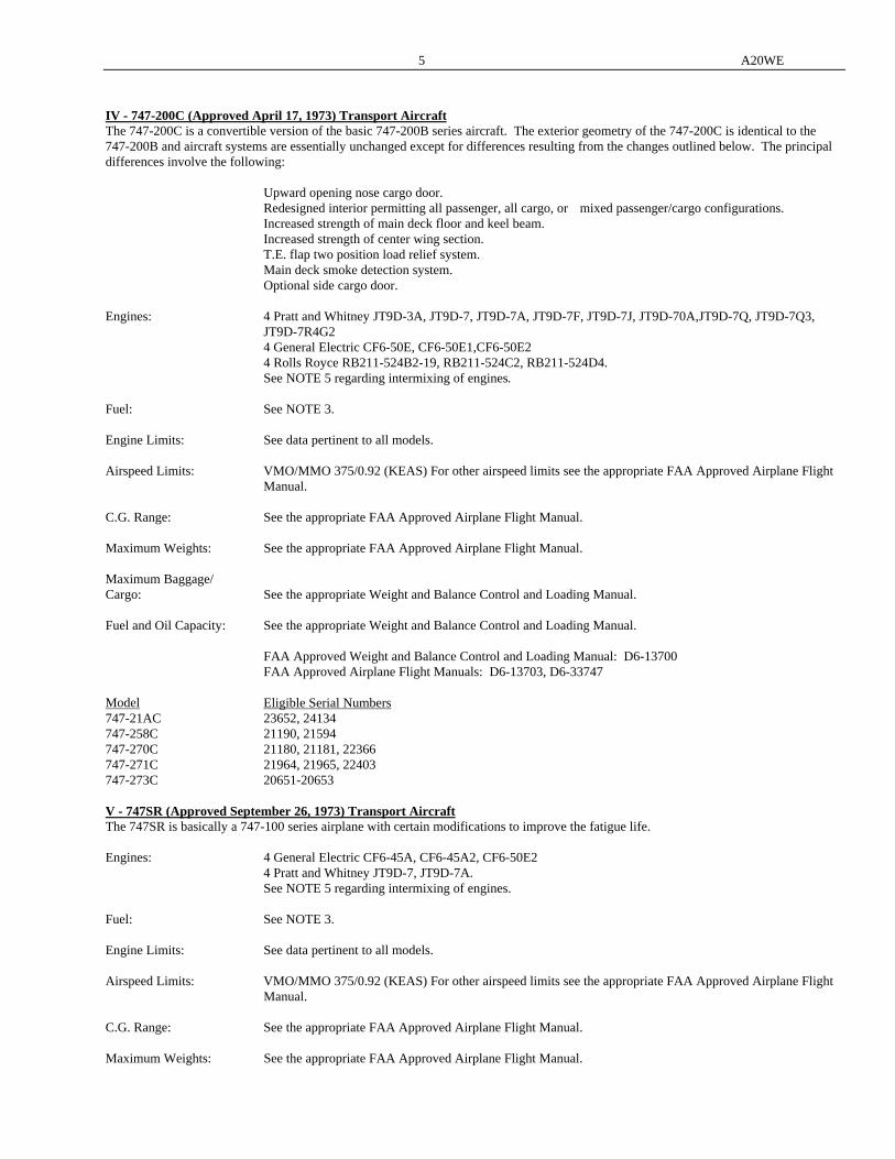
IV - 747-200C (Approved April 17, 1973) Transport Aircraft The 747-200C is a convertible version of the basic 747-200B series aircraft. The exterior geometry of the 747-200C is identical to the 747-200B and aircraft systems are essentially unchanged except for differences resulting from the changes outlined below. The principal differences involve the following: Upward opening nose cargo door. Redesigned interior permitting all passenger, all cargo, or mixed passenger/cargo configurations. Increased strength of main deck floor and keel beam. Increased strength of center wing section. T.E. flap two position load relief system. Main deck smoke detection system. Optional side cargo door. Engines: 4 Pratt and Whitney JT9D-3A, JT9D-7, JT9D-7A, JT9D-7F, JT9D-7J, JT9D-70A,JT9D-7Q, JT9D-7Q3,
JT9D-7R4G2 4 General Electric CF6-50E, CF6-50E1,CF6-50E2 4 Rolls Royce RB211-524B2-19, RB211-524C2, RB211-524D4. See NOTE 5 regarding intermixing of engines. Fuel: See NOTE 3. Engine Limits: See data pertinent to all models. Airspeed Limits: VMO/MMO 375/0.92 (KEAS) For other airspeed limits see the appropriate FAA Approved Airplane Flight
Manual. C.G. Range: See the appropriate FAA Approved Airplane Flight Manual. Maximum Weights: See the appropriate FAA Approved Airplane Flight Manual. Maximum Baggage/ Cargo: See the appropriate Weight and Balance Control and Loading Manual. Fuel and Oil Capacity: See the appropriate Weight and Balance Control and Loading Manual. FAA Approved Weight and Balance Control and Loading Manual: D6-13700 FAA Approved Airplane Flight Manuals: D6-13703, D6-33747 Model Eligible Serial Numbers 747-21AC 23652, 24134 747-258C 21190, 21594 747-270C 21180, 21181, 22366 747-271C 21964, 21965, 22403 747-273C 20651-20653 V - 747SR (Approved September 26, 1973) Transport Aircraft The 747SR is basically a 747-100 series airplane with certain modifications to improve the fatigue life. Engines: 4 General Electric CF6-45A, CF6-45A2, CF6-50E2 4 Pratt and Whitney JT9D-7, JT9D-7A. See NOTE 5 regarding intermixing of engines. Fuel: See NOTE 3. Engine Limits: See data pertinent to all models. Airspeed Limits: VMO/MMO 375/0.92 (KEAS) For other airspeed limits see the appropriate FAA Approved Airplane Flight
Manual. C.G. Range: See the appropriate FAA Approved Airplane Flight Manual. Maximum Weights: See the appropriate FAA Approved Airplane Flight Manual.
A20WE 6
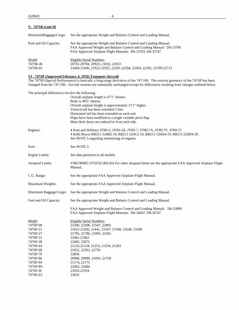
V. 747SR (cont’d) MaximumBaggage/Cargo: See the appropriate Weight and Balance Control and Loading Manual. Fuel and Oil Capacity: See the appropriate Weight and Balance Control and Loading Manual. FAA Approved Weight and Balance Control and Loading Manual: D6-13700 FAA Approved Airplane Flight Manuals: D6-13703, D6-33747 Model Eligible Serial Numbers 747SR-46 20781-20784, 20923, 21032, 21033 747SR-81 21604-21606, 21922-21925, 22291-22294, 22594, 22595, 22709-22712 VI - 747SP (Approved February 4, 1976) Transport Aircraft The 747SP (Special Performance) is basically a long-range derivative of the 747-100. The exterior geometry of the 747SP has been changed from the 747-100. Aircraft systems are essentially unchanged except for differences resulting from changes outlined below. The principal differences involve the following: Overall airplane length is 47'1" shorter. Body is 48'5" shorter. Overall airplane height is approximately 2'11" higher. Vertical tail has been extended 5 feet. Horizontal tail has been extended on each end. Flaps have been modified to a single variable pivot flap. Main deck doors are reduced to 4 on each side. Engines: 4 Pratt and Whitney JT9D-3, JT9D-3A, JT9D-7, JT9D-7A, JT9D-7F, JT9D-7J 4 Rolls Royce RB211-524B2-19, RB211-524C2-19, RB211-524D4-19, RB211-524D4-39. See NOTE 5 regarding intermixing of engines. Fuel: See NOTE 3. Engine Limits: See data pertinent to all models. Airspeed Limits: VMO/MMO 375/0.92 (KEAS) For other airspeed limits see the appropriate FAA Approved Airplane Flight
Manual. C.G. Range: See the appropriate FAA Approved Airplane Flight Manual. Maximum Weights: See the appropriate FAA Approved Airplane Flight Manual. Maximum Baggage/Cargo: See the appropriate Weight and Balance Control and Loading Manual. Fuel and Oil Capacity: See the appropriate Weight and Balance Control and Loading Manual. FAA Approved Weight and Balance Control and Loading Manual: D6-33800 FAA Approved Airplane Flight Manuals: D6-34047, D6-36747 Model Eligible Serial Numbers 747SP-09 21300, 22298, 22547, 22805 747SP-21 21022-21026, 21441, 21547, 21548, 21648, 21649 747SP-27 21785, 21786, 21992, 22302 747SP-31 21961-21963 747SP-38 22495, 22672 747SP-44 21132-21134, 21253, 21254, 21263 747SP-68 21652, 22503, 22750 747SP-70 22858 747SP-86 20998, 20999, 21093, 21758 747SP-94 21174, 21175 747SP-B5 22483, 22484 747SP-J6 21932-21934 747SP-Z5 23610

7 A20WE
VII - 747-100B (Approved August 1, 1979) Transport Aircraft The 747-100B is basically a 747SR series airplane with certain modifications to permit increases in maximum permissible operating weights. Engines: 4 Pratt and Whitney JT9D-7A, JT9D-7F 4 Rolls Royce RB2ll-524B2-19, RB211-524C2-19, RB211-524D4-19, RB211-524D4-39. See NOTE 5 regarding intermixing of engines. Fuel: See NOTE 3. Engine Limits: See data pertinent to all models. Airspeed Limits: VMO/MMO 375/0.92 (KEAS) For other airspeed limits see the appropriate FAA Approved Airplane Flight
Manual. C.G. Range: See the appropriate FAA Approved Airplane Flight Manual. Maximum Weights: See the appropriate FAA Approved Airplane Flight Manual. Maximum Baggage/Cargo: See the appropriate Weight and Balance Control and Loading Manual. Fuel and Oil Capacity: See the appropriate Weight and Balance Control and Loading Manual. FAA Approved Weight and Balance Control and Loading Manual: D6-13700 FAA Approved Airplane Flight Manuals: D6-13703, D6-35747 Model Eligible Serial Numbers 747-146B 22066, 22067, 23150 747-168B 22498-22502, 22747-22749 747-186B 21759 See NOTE 7. VIII - 747-300 (Approved March 1, 1983) Transport Aircraft The 747-300 is basically a 747-200 series airplane with a stretched upper deck. Engines: 4 Pratt and Whitney JT9D-7R4G2 4 General Electric CF6-50E2, CF6-80C2B1 4 Rolls Royce RB211-524B2-19, RB211-524C2-19, or RB211-524D4-19, RB211-524D4-39.
See NOTE 5 regarding intermixing of engines. Fuel: See NOTE 3. Engine Limits: See data pertinent to all models. Airspeed Limits: VMO/MMO 375/0.92 (KEAS) For other airspeed limits see the appropriate FAA Approved Airplane Flight
Manual. C.G. Range: See the appropriate FAA Approved Airplane Flight Manual. Maximum Weights: See the appropriate FAA Approved Airplane Flight Manual. Maximum Baggage/Cargo: See the appropriate Weight and Balance Control and Loading Manual. Fuel and Oil Capacity: See the appropriate Weight and Balance Control and Loading Manual. FAA Approved Weight and Balance Control and Loading Manual: D6-13700 FAA Approved Airplane Flight Manuals: D6-13703, D6-33747, D6-35747
A20WE 8
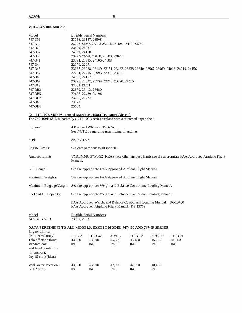
VIII – 747-300 (cont’d): Model Eligible Serial Numbers 747-306 23056, 23137, 23508 747-312 23026-23033, 23243-23245, 23409, 23410, 23769 747-329 23439, 24837 747-337 24159, 24160 747-338 23222-23224, 23408, 23688, 23823 747-341 23394, 23395, 24106-24108 747-344 22970, 22971 747-346 23067, 23068, 23149, 23151, 23482, 23638-23640, 23967-23969, 24018, 24019, 24156 747-357 22704, 22705, 22995, 22996, 23751 747-366 24161, 24162 747-367 23221, 23392, 23534, 23709, 23920, 24215 747-368 23262-23271 747-3B3 22870, 23413, 23480 747-3B5 22487, 22489, 24194 747-3D7 23721, 23722 747-3G1 23070 747-3H6 23600 IX - 747-100B SUD (Approved March 24, 1986) Transport Aircraft The 747-100B SUD is basically a 747-100B series airplane with a stretched upper deck. Engines: 4 Pratt and Whitney JT9D-7A See NOTE 5 regarding intermixing of engines. Fuel: See NOTE 3. Engine Limits: See data pertinent to all models. Airspeed Limits: VMO/MMO 375/0.92 (KEAS) For other airspeed limits see the appropriate FAA Approved Airplane Flight
Manual. C.G. Range: See the appropriate FAA Approved Airplane Flight Manual. Maximum Weights: See the appropriate FAA Approved Airplane Flight Manual. Maximum Baggage/Cargo: See the appropriate Weight and Balance Control and Loading Manual. Fuel and Oil Capacity: See the appropriate Weight and Balance Control and Loading Manual. FAA Approved Weight and Balance Control and Loading Manual: D6-13700 FAA Approved Airplane Flight Manual: D6-13703 Model Eligible Serial Numbers 747-146B SUD 23390, 23637 DATA PERTINENT TO ALL MODELS, EXCEPT MODEL 747-400 AND 747-8F SERIES Engine Limits: (Pratt & Whitney) JT9D-3 JT9D-3A JT9D-7 JT9D-7A JT9D-7F JT9D-7J Takeoff static thrust 43,500 43,500 45,500 46,150 46,750 48,650 standard day, lbs. lbs. lbs. lbs. lbs. lbs. seal level conditions (in pounds); Dry (5 min) (Ideal) With water injection 43,500 45,000 47,000 47,670 48,650 (2 1/2 min.) lbs. lbs. lbs. lbs. lbs.
9 A20WE
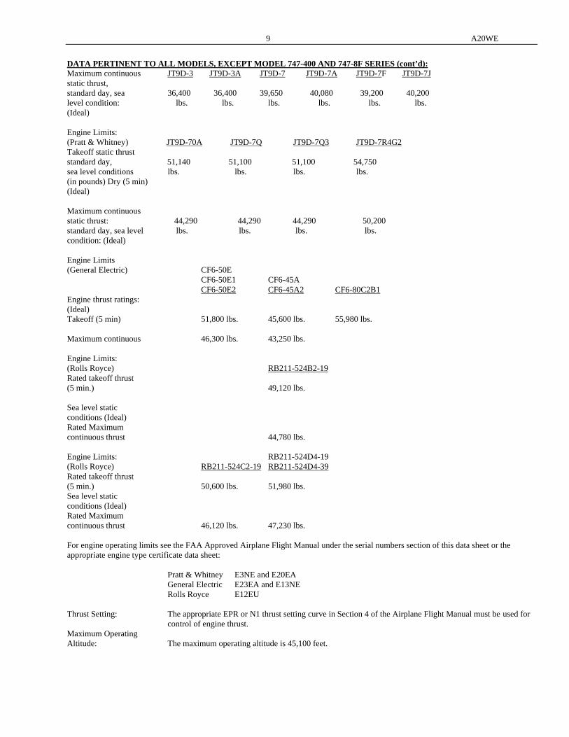
DATA PERTINENT TO ALL MODELS, EXCEPT MODEL 747-400 AND 747-8F SERIES (cont’d): Maximum continuous JT9D-3 JT9D-3A JT9D-7 JT9D-7A JT9D-7F JT9D-7J static thrust, standard day, sea 36,400 36,400 39,650 40,080 39,200 40,200 level condition: lbs. lbs. lbs. lbs. lbs. lbs. (Ideal) Engine Limits: (Pratt & Whitney) JT9D-70A JT9D-7Q JT9D-7Q3 JT9D-7R4G2 Takeoff static thrust standard day, 51,140 51,100 51,100 54,750 sea level conditions lbs. lbs. lbs. lbs. (in pounds) Dry (5 min) (Ideal) Maximum continuous static thrust: 44,290 44,290 44,290 50,200 standard day, sea level lbs. lbs. lbs. lbs. condition: (Ideal) Engine Limits (General Electric) CF6-50E CF6-50E1 CF6-45A CF6-50E2 CF6-45A2 CF6-80C2B1 Engine thrust ratings: (Ideal) Takeoff (5 min) 51,800 lbs. 45,600 lbs. 55,980 lbs. Maximum continuous 46,300 lbs. 43,250 lbs. Engine Limits: (Rolls Royce) RB211-524B2-19 Rated takeoff thrust (5 min.) 49,120 lbs. Sea level static conditions (Ideal) Rated Maximum continuous thrust 44,780 lbs. Engine Limits: RB211-524D4-19 (Rolls Royce) RB211-524C2-19 RB211-524D4-39 Rated takeoff thrust (5 min.) 50,600 lbs. 51,980 lbs. Sea level static conditions (Ideal) Rated Maximum continuous thrust 46,120 lbs. 47,230 lbs. For engine operating limits see the FAA Approved Airplane Flight Manual under the serial numbers section of this data sheet or the appropriate engine type certificate data sheet: Pratt & Whitney E3NE and E20EA General Electric E23EA and E13NE Rolls Royce E12EU Thrust Setting: The appropriate EPR or N1 thrust setting curve in Section 4 of the Airplane Flight Manual must be used for
control of engine thrust. Maximum Operating Altitude: The maximum operating altitude is 45,100 feet.

A20WE 10
DATA PERTINENT TO ALL MODELS, EXCEPT MODEL 747-400 AND 747-8F SERIES (cont’d): Minimum Crew: For all flights, 3 persons (pilot, copilot, flight engineer). When passengers are being carried, one attendant is
required at each No. 3 over-wing exit. At least one flight attendant is required on the upper deck during taxi, takeoff and landing when passengers occupy the upper deck.
Maximum Passengers: For 747SR and 747-100, -100B, -200B, -200C airplanes the total passenger capacity is limited to: 550 with 5 pair of Type "A" exits on main deck 440 with 4 pair of Type "A" exits on main deck Upper deck passenger capacity is limited to: 8 with one exit on the upper deck 16 with one exit, improved slide and smoke barrier 24 with one exit, straight stairway, smoke barrier, and escape slide capable of operation in 25 kt. wind 32 if in compliance with the requirements of Special Condition No. 25-61-NW-1 45 if in compliance with the requirements of Special Condition No. 25-71-NW-3 5 persons on upper deck per Exemption 1870D. (747-100 and 747-200) For 747SP the total passenger capacity is limited to: 400 passengers with the same upper deck limits as listed above. For 747-200F the total passenger capacity is limited to: 19 passengers on upper deck with 2 doors, 25 knot slides, C.G. Limitation, and compliance shown
with AD 93-07-15; or 19 persons on upper deck equipped with emergency descent reels and harnesses, 2 doors and 25 knot slides.
5 persons on upper deck per Exemption 1870D. For 747-300 and 747-100B SUD the total passenger capacity is limited to: 660 passengers with 5 pair of Type "A" exits on the main deck plus one pair of Type "A"exits on
the upper deck. Main deck limited to 550 and upper deck limited to 110 if in compliance with the requirements of modified Special Condition No. 25-71-NW-3, transmitted to Boeing by FAA letter dated August 3, 1981.) See NOTE 9.
550 passengers with 4 pair of Type "A" exits on the main deck limited to 440 and upper deck
limited to 110 if in compliance with the requirements of modified Special Condition No. 25-71-NW-3, transmitted to Boeing by FAA letter dated August 3, 1981.
Required Equipment: The basic required equipment as prescribed in the applicable airworthiness regulations (See Certification
Basis) must be installed in the aircraft for certification. The required equipment is noted in the Type Design Data.
Datum: Balance Arm Datum corresponds to Body Station 0 and is 90 inches (290 inches on SP) forward of nose. All
productions stations coincide numerically with arms except on 747SP. Horizontal distance of datum to nose gear jack points in 384.7 inches. (584.7 inches on 747SP) Mean Aerodynamic Chord (MAC): MAC length is 327.8 inches. Leading edge of MAC is 1258 inches aft of datum. Level Means: A plumb-bob attachment and leveling provision scale are provided in the R.H. body wheel well at BS
1444.0. They are referred to as ARM on the 747SP and are a true measure in inches aft of a forward reference datum which is located 290 inches ahead of the airplane nose.
Balance ARMS have the following relationship with Body Stations on the 747SP: BODY STATION ADJUSTMENT ARM INCHES INCHES INCHES 90 to 800 +200 290 to 1,000 (800 to 1,000 Section removed) 1,000 to 1,480 0 1,000 to 1,480 (1,480 to 1,640 Section removed) 1,640 to 2,140 -160 1,480 to 1,980 (2,140 to 2,360 Section removed) 2,360 to 2,792 -380 1,980 to 2,412

11 A20WE
DATA PERTINENT TO ALL MODELS, EXCEPT MODEL 747-400 AND 747-8F SERIES (cont’d): Control Surface Movements: To insure proper operation of the airplane, the movement of the various control surfaces must be carefully
controlled by proper rigging of the flight control systems. The airplane must, therefore, be rigged according to the following FAA-approved data:
Boeing Drawing Numbers 65B04001 Control Installation Aileron and Spoiler 65B04002 Control Installation Elevator 65B04003 Control Installation Rudder 65B04004 Control Installation Stabilizer Trim 65B04006 Control Installation Rudder Trim 65B04007 Control Installation Wing Flap 65B04016 Control Installation Speed Brakes Service Information: Boeing Reports D6-13592, "Structural Repair Manual", (except for 747SP) is FAA-Approved. Boeing Reports D6-34024, "Structural Repair Manual", is FAA-Approved for the 747SP. Service Bulletins and other service information, when FAA-Approved, will carry a statement to the effect. Certification Basis: FAR Part 1, FAR Part 21, FAR Part 36, FAR Part 25 effective February 1, 1965, Amendments 25-1 through
25-8 plus 25-15, 25-17, 25-18, 25-20, and Amendment 25-39 transmitted by FAA letter dated February 4, 1977, and special conditions summarized for record purposes as enclosed with FAA letter to The Boeing Company dated February 20, 1970. Special Condition 4A, revised to apply to airplanes with the landing gear load evener system deleted, was recorded as attachment to an FAA letter to The Boeing Company dated May 12, 1971.
Based on 14 CFR § 21.101(g) for changes to TC’s, applicable provisions of 14 CFR part 26 are included in
the certification basis. For any future 14 CFR part 26 amendments, the holder of this TC must demonstrate compliance with the applicable sections.
Amendment 25-46, Section 25.803(d) transmitted by FAA letter to The Boeing Company dated September 2,
1983. This is limited to all passenger configurations and 6/7 pallet combi configurations for Model 747-100, -200, and -300 series airplanes.
Exemptions from 14 CFR part 25: 1. Exemption from 14 CFR 25.807(c)(1), 25.807(c)(5), 25.809(f)(1), 25.813(b), Allowance of non crew
members on the upper deck of 747-200F, 747-200C and certain 747-100 airplanes when in the main deck cargo configuration. (Exemption No. 1870 dated September 14, 1973, No. 1870A dated March 10, 1977, No. 1870B dated October 26, 1981, No. 1870C dated June 2, 1986, and No. 1870D dated April 3, 1991)
Special Condition No. 25-61-NW-1 for occupancy not to exceed 32 passengers on the upper deck of
airplanes with spiral staircase was transmitted to The Boeing Company by FAA letter dated February 26, 1975.
Special Condition No. 25-71-NW-3 for occupancy not to exceed 45 passengers on the upper deck of
airplanes with straight segmented stairway was transmitted to The Boeing Company by FAA letter dated September 8, 1976.
Modification of Special Condition No. 25-71-NW-3 for occupancy not to exceed 110 passengers on the
upper deck of airplanes with straight segmented stairway was transmitted to The Boeing Company by FAA letter dated August 3, 1981.
RB211 engine oil filter system complies with FAR 25.1019 and 25.1305(c)(7) of Amendment 25-36. Special Condition No. 25-77-NW-4 (modification of the autopilot system to approve the airplane for use of
the system under category IIIb landing conditions) was transmitted to The Boeing Company by FAA letter dated July 8, 1977.
Special Condition No. 25-ANM-16 for installation of an overhead crew rest area, occupancy not to exceed
10 crewmembers. FAA approved procedures required for compliance with paragraph 3 of the Special Condition are located in Boeing Document D926U303, Appendix D.
A20WE 12
DATA PERTINENT TO ALL MODELS, EXCEPT MODEL 747-400 AND 747-8F SERIES (cont’d): Special Condition No. 25-ANM-16A for installation of an overhead crew rest area with hard partitions and a
curtain, occupancy not to exceed 10 crewmembers. FAA approved procedures required for compliance with paragraph 2 and 13(e) of the Special Condition are located in Boeing Document D926U303, Appendix D and E.
Compliance with the following optional requirements has been established: Ditching Provisions FAR 25.801
Ice Protection Provisions FAR 25.1419 Equivalent Safety Findings exist with respect to the following Regulations: For Model 747-100, -200B, -200F, -200C, 747SR, 747SP, -100B, -300, -100B SUD: 25.1415(d) Emergency Locator Transmitter (ELT) 25.561(b)(3)(ii) Passenger (and non-crewmember) seat track bending calculations only per FAA
Memorandum TD6633SE-T-C-1, dated January 26, 2004. For 747-300 only: 25.812(k)(2) 25.815 For Model 747-100, -200, -300 Series: 25.773(b)(2)(i), Amendments 25-1 through 25-67 25.811(f) Emergency Exit Marking Production Basis: Production Certificate No. 700. Equipment: The basic required equipment as prescribed in the applicable airworthiness regulations (See Certification
Basis) must be installed. X - 747-400 (Approved January 10, 1989) Transport Aircraft The 747-400 is basically 747-300 series airplane with wing extension and winglets, additional fuel tank in the horizontal stabilizer, additional auxiliary fuel tank in the forward section of the cargo bay and reconfigured cockpit for two man crew and associated automation and advanced avionics. Engines: 4 Pratt and Whitney PW4000 Series General Electric CF6-80C2B1F, CF6-80C2B5F Rolls Royce RB211-524G2-19, RB211-524G3-19, RB211-524H2-19, RB211-524G2-T-19, RB211-524G3-
T-19, RB211-524H2-T-19. WARNING: To prevent unsafe airplane handling characteristics, PW4000 series engines with electronic
Engine control (EEC) part number 791100-14-102 (Pratt & Whitney part number 54D043) must not be installed on the same airplane as PW4000 series engines that have the ring case compressor configuration. This combination of engine configurations is not approved because of a significant difference in engine acceleration rates and the effect of that difference on airplane handling characteristics. Ring case compressor equipped engines were approved with the same engine model number as previously approved PW4000 configurations, and must be identified by the presence of a “/A5” marked at the end of the “INSTL ARR” block on the engine data plate.
SEE NOTE 5 for further information regarding intermixing engines Engine Thrust Limits: See data pertinent to all Model 747-400's Fuel: See NOTE 3. Airspeed Limits: VMO/MMO 365/0.92 (KCAS) For other airspeed limits see the appropriate FAA Approved Airplane Flight
Manual.
13 A20WE
X. 747-400 (cont’d): C.G. Range: See the appropriate FAA Approved Airplane Flight Manual. Maximum Weights: See the appropriate FAA Approved Airplane Flight Manual. Maximum Baggage/Cargo: See the appropriate Weight and Balance Control and Loading Manual. Fuel/Oil Capacity: See the appropriate Weight and Balance Control and Loading Manual. FAA Approved Weight and Balance Control and Loading Manual: D043U400 FAA Approved Airplane Flight Manuals: D6-U10001, D6-U10002, and D6-U10003 Model Eligible Serial Numbers 747-406 23982, 23999-24001, 24201, 24202, 24517, 24518, 25086, 25087, 25356, 25413, 26372-26374, 27202,
28195, 28196, 28459, 28460, 30454, 30455 747-409 24309-24313, 27965, 28709-28712, 29030, 29031, 29219, 29906, 33734-33737 747-412 24061-24066, 24226, 24227, 24975, 25068, 25127, 25128, 26547-26552, 26554-26557, 26562, 27066-
27071, 27132-27134, 27137, 27178, 27217, 28022, 28023, 28025, 28028, 28029, 28031, 29950 747-419 24386, 24855, 25605, 26910, 29375 747-422 24322, 24363, 24380-24385, 25158, 25224, 25278, 25279, 25379, 25380, 25395, 26875-26881, 26890,
26892, 26899-26903, 26906, 26908, 28715-28717, 28810-28813, 29166-29168, 30023 747-428 24969, 24990, 25238, 25302, 25344, 25599-25602, 25628-25630, 32868, 32869, 32871 747-430 23816, 23817, 24285-24288, 24715, 24740, 24741, 24761, 24966, 24967, 25045-25047, 26425-26427,
28086, 28284-28287, 29101, 29492, 29493, 29868-29872, 32445 747-433 24998, 25074, 25075 747-436 23908-23911, 24047-24058, 24447, 24629, 24630, 25406, 25427, 25432, 25434, 25435, 25809, 25810-
25814, 25817-25824, 27090-27092, 27349, 27350, 27478, 28700, 28848-28859, 747-437 27078, 27164, 27165, 27214, 28094, 28095 747-438 24354, 24373, 24406, 24481-24483, 24779, 24806, 24887, 24974, 25067, 25151, 25245, 25315, 25544-
25547, 25564-25566, 32909-32914 747-441 24956, 24957 747-443 30885, 32337-32340 747-444 24976, 25152, 26637, 26638, 28468, 29119 747-446 24423-24427, 24777, 24784, 24870, 24885, 24886, 25064, 25212, 25260, 25308, 26341-26344, 26346,
26350, 26353, 26355, 26356, 26359-26362, 27099, 27100, 27645, 27646, 27648, 27650, 29899 747-451 23719, 23720, 23818-23821, 24222-24225, 26473, 26474, 26477, 30267-30269, 33001, 33002 747-458 26055, 26056, 27915, 29328 747-467 23814, 23815, 24631, 24850, 24851, 24925, 24955, 25082, 25211, 25351, 25869-25874, 27117, 27230,
27595 747-468 28339-28343 747-469 27338, 27663 747-475 24883, 24895, 24896, 25422 747-481 24801, 24833, 24920, 25135, 25207, 25641, 25645, 28282, 28283, 29262, 29263, 30322 747-41R 29406, 32745, 32746 747-45E 26062, 27062, 27063, 27141, 27142, 27154, 27173, 27174, 27898, 27899, 28092, 28093, 29061, 29111,
29112 747-47C 24730, 24731 747-48E 25405, 25452, 25777-25780, 25782, 25784, 28551, 28552 747-4B3 24154, 24155 747-4B5 24198-24200, 24619, 24621, 25205, 25275, 26392-26398, 26400, 26402-26405, 26407, 26409, 26412,
27072, 27177, 27341, 27662, 28096, 28335 747-4D7 24458, 24459, 24993, 25366, 26609, 26610, 26615, 26616, 27093, 27723- 27725, 28705, 28706, 32369-
32370 , 33770, 33771 747-4F6 27261, 27262, 27602, 27827, 27828, 28959-28961 747-4H6 24315, 24405, 24836, 25126, 25699-25703, 27042-27044, 27672, 28426-28428, 28432, 28433, 28435,
29900, 29901, 30158 747-4J6 24346-24348, 25879-25883, 28754-28756, 29070, 29071, 30158 747-4P8 33684 747-4Q3 29486 747-4Q8 24958, 26255, 26326, 28194, 28757 747-4U3 25704, 25705
A20WE 14
X. 747-400 (cont’d): For engine operating limits see the FAA Approved Airplane Flight Manual referenced under Section X of this data sheet or the appropriate engine type certificate data sheet: Pratt and Whitney: E24NE General Electric: E13NE Rolls Royce: E30NE Thrust Setting: The appropriate EPR or N1 thrust setting curves in Section 4 of the Airplane Flight Manual (AFM) must be
used for control of engine thrust. Maximum Operating Altitude: 45,100 feet Minimum Crew: For all flights, 2 persons (pilot, copilot). When passengers are being carried, one attendant is required at
each No. 3 over-wing exit. At least one flight attendant is required on the upper deck during taxi, takeoff, and landing when passengers occupy the upper deck.
Maximum Passengers: For 747-400 the total passenger capacity is limited to: 660 passengers with 5 pair of Type "A" exits on main deck plus one pair of Type "A" exits on the upper
deck. (Main deck limited to 550 and upper deck limited to 110 if in compliance with the requirements of modified Special Condition Number 25-71-NW-3, transmitted to Boeing by FAA letter dated August 3, 1981.) See NOTE 9.
Required Equipment: The basic required equipment as prescribed in the applicable airworthiness regulations (See Certification
Basis) must be installed in the aircraft for certification. The required equipment is noted in the Type Design Data.
Datum: Balance Arm Datum corresponds to Body Station 0 and is 90 inches forward of nose. All productions
stations coincide numerically with arms. Horizontal distance of datum to nose gear jack points is 384.7 inches.
MAC: MAC length is 327.8 inches. Leading edge of MAC is 1258 inches aft of datum. Level Means: A plumb-bob attachment and leveling provision scale are provided in the R.H. body wheel well at BS
1444.0. Control Surface Movements: To insure proper operation of the airplane, the movement of the various control surfaces must be carefully
controlled by proper rigging of the flight control systems. The airplane must, therefore, be rigged according to the following FAA-approved data:
Boeing Drawing Numbers: 251U1001 Rigging Procedures Aileron and Spoiler 251U2001 Rigging Procedures Elevator 251U3002 Rigging Procedures Rudder 251U4001 Rigging Procedures Stabilizer Trim 253U5001 Rigging Procedure - Control Stand (Includes flap control assembly) 256U2001 Rigging Procedures Leading Edge Flaps 256U3001 Rigging Procedures Trailing Edge Flaps 251U1003 Rigging Procedures Speed Brakes Service Information: Boeing Report D634U102, "Structural Repair Manual," is FAA-approved. Service Bulletins and other
Service information, when FAA-approved, will carry a statement to that effect. Certification Basis: Part 25 of the FAR, effective February 1, 1965, as amended by Amendments 25-1 through 25-59 with the
following exceptions: SECTION NO. TITLE THRU AMDT.25- 25.107 Takeoff speeds 41 25.109 Accelerate-stop distance 41 25.149 Minimum control speed 41
15 A20WE
X. 747-400 (cont’d): 25.251 Vibration and buffeting 22 25.305 Strength and deformation 22 25.331 General 45 25.351 Yawing conditions 45 25.365 Pressurized cabin loads 53 25.571 Damage-tolerance and fatigue evaluation of structure 9 25.607 Fasteners 22 25.631 Bird Strike damage (NA)** 25.657 Hinges 22 25.675 Stops 37 25.683 Operation tests 22 25.772 Pilot compartment doors 46 25.773(b)(2)(ii) Pilot Compartment View 72 25.783 Doors 53 25.785 Seats, berths, safety belts, harnesses 50 25.787 Stowage Compartments 31 25.789 Retention of items of mass in passenger and crew compartments 45 25.809 Emergency exit arrangement 45 25.812 Emergency lighting 31 25.832 Cabin ozone concentration (NA)** 25.858 Cargo compartment fire detections systems (NA)** 25.1103 Induction system ducts and air duct systems 45 25.1401 Anticollision light system 26 25.1438 Pressurization and pneumatic systems (NA)** 25.1529 Instructions for continued airworthiness (NA)** **Not applicable - The requirements of this section do not apply to this type design because the original
certification basis, which did not include this section, has been determined to be adequate. Based on 14 CFR § 21.101(g) for changes to TC’s, applicable provisions of 14 CFR part 26 are included in
the certification basis. For any future 14 CFR part 26 amendments, the holder of this TC must demonstrate compliance with the applicable sections.
Compliance has been found for the following regulations at Amendment 26-0: 26.11 Compliance has been found for the following regulations at Amendment 26-1: 26.43, 26.45, 26.47, and 26.49 Part 36 of the FAR as amended by Amendments 36-1 through 36-15, and any later amendments in existence
at the time of certification. Special Federal Aviation Regulation (SFAR) 27, as amended by Amendments 27-1 through 27-6 and any
later amendments in existence at the time of type certification. The following special conditions, exemptions; and equivalent safety findings, which are part of the Model
747-300 certification basis, are also part of the certification basis for the Model 747-400. The special conditions include those enclosed with FAA letter to The Boeing Company dated February 20, 1970, and the following:
1. Special Condition 4A, revised to apply to airplanes with the landing gear load evener system deleted,
was recorded as an enclosure to an FAA letter to The Boeing Company dated May 12, 1971. 2. Special Condition No. 25-61-NW-1 for occupancy not to exceed 32 passengers on the upper deck of
airplanes with spiral staircase was transmitted to The Boeing Company by FAA letter dated February 26, 1975.
3. Special Condition No. 25-71-NW-3 for occupancy not to exceed 45 passengers on the upper deck of
airplanes with straight segmented stairway was transmitted to The Boeing Company by FAA letter dated September 8, 1976.
A20WE 16
X. 747-400 (cont’d): 4. Modification of Special Condition No. 25-71-NW-3 for occupancy not to exceed 110 passengers on
the upper deck of airplanes with straight segmented stairway was transmitted to The Boeing Company by FAA letter dated August 3, 1981.
5. Special Condition No. 25-77-NW-4 (modification of the auto pilot system to approve the airplane for
use of the system under Category IlIb landing conditions) was transmitted to The Boeing Company by FAA letter dated July 8, 1977.
6. Special Condition No. 25-ANM-16 for use of an overhead crew rest area, occupancy not to exceed ten
crewmembers was transmitted to The Boeing Company by FAA letter dated November 19, 1987. FAA approved procedures required for compliance with paragraph 13 of the Special Condition are located in Boeing Document D926U303, Appendix D.
7. Special Condition No. 25-ANM-24 applicable to flight deck displays and propulsion control system was
provided to Boeing on December 22, 1988. 8. Special Condition No. 25-ANM-25 which established lightning and radio frequency (RF) energy
protection requirements was provided to Boeing on December 22, 1988. 9. Special Condition No. 25-ANM-16A for installation of an overhead crew rest area with hard partitions
and a curtain, occupancy not to exceed 10 crewmembers. FAA approved procedures required for compliance with paragraph 2 and 13(e) of the Special Condition are located in Boeing Document D926U303, Appendix D and E.
The following optional requirements, which are part of the Model 747-300 certification basis, apply also to
the 747-400: Ditching Provisions Section 25.801 Ice Protection Provisions Section 25.1419 The following equivalent safety findings, previously made for earlier models under the provisions of Section
21.21(b)(1), are also applicable to the Model 747-400: Width of Aisle Section 25.815 Pilot Compartment View Section 25.773 Use of 1-g Stall Speed (nonstructural items) Several (747-400 only) Use of 1-g Stall Speed (structural items) Several (747-400 only) Position Light Distribution and Intensities Section 25.1389(b)(3) (747-400 only) Fire-detection System Section 25.1203 See Note 1. Pressure Relief Section 25.1103(d) See Note 1. Emergency Locator Transmitter (ELT) Section 25.1415(d) Emergency Exit Marking Section 25.811(f) Note 1: Applies to RB211-524G/H series engine installations only. Equivalent Safety Findings exist with respect to the following Regulation: 25.773(b)(2)(i), Amendments 25-1
throught 25-67 (Boeing 747-400 Series) Part 25 of the FAR, effective February 1, 1965, as amended by Amendment 25-1 through 25-59 With the
following exceptions: (See Note 15).
17 A20WE
X. 747-400 (cont’d): Exemptions from FAR Part 25: Exemption from 14 CFR 25.779(b)(1), 25.1301(d), and 25.1309(a), 747-400F with Rolls Royce RB211-524G/H engines
installed with Full Authority Fuel Control Software “Issue 17” software (Exemption 10069, dated May 25, 2010) Certification Maintenance Requirements (CMR's): The CMR's are listed in either the FAA-approved Section 9 of Boeing Maintenance Planning Data Document
D621U400 or the applicable engine Type Certificate Data Sheet. The more restrictive requirement from these two documents shall be in force.
Production Basis: Production Certificate No. 700 has been issued to The Boeing Company. Equipment: The basic required equipment as prescribed in the applicable airworthiness regulations (see Certification
Basis) must be installed in the aircraft. XI - 747-400D (Approved October 10, 1991) Transport Aircraft The 747-400D is basically the 747-400 series airplane with strengthened wings and without the 6-foot wing tip extension and 6-foot winglet. It is delivered with a wing tip equivalent in planform to the 747-300 airplane and has provisions for a "one-time" conversion from the Domestic configuration to the International configuration by adding the 747-400 wing extension and winglet. Engines: 4 General Electric CF6-80C2B1F Engine Thrust Limits: See data pertinent to all Model 747-400's Fuel: See NOTE 3. Airspeed Limits: VMO/MMO 365/0.92 (KCAS) For other airspeed limits see the appropriate FAA Approved Airplane Flight
Manual. C.G. Range: See the appropriate FAA Approved Airplane Flight Manual. Maximum Weights: See the appropriate FAA Approved Airplane Flight Manual. Maximum Baggage/Cargo: See the appropriate Weight and Balance Control and Loading Manual. Fuel and Oil Capacity: See the appropriate Weight and Balance Control and Loading Manual. FAA Approved Weight and Balance Control and Loading Manual: D043U400 FAA Approved Airplane Flight Manual: D6U10002 Model Eligible Serial Numbers 747-446D 25213, 25214, 26345, 26347-26349, 26351, 26352 747-481D 25292, 25639, 25640, 25642-25644, 25646, 25647, 27163, 27436, 27442 For engine operating limits see the FAA Approved Airplane Flight Manual referenced under Section XI of this data sheet or the appropriate engine type certificate data sheet: General Electric: E13NE Thrust Setting: The appropriate EPR or N1 thrust setting curves in Section 4 of the Airplane Flight Manual (AFM) must be
used for control of engine thrust. Maximum Operating Altitude: 45,100 feet Minimum Crew: For all flights, 2 persons (pilot, copilot). When passengers are being carried, one attendant is required at
each No. 3 over-wing exit. At least one flight attendant is required on the upper deck during taxi, takeoff, and landing when passengers occupy the upper deck.
Maximum Passengers: For 747-400D airplanes the total passenger capacity is Limited to: 660 passengers with 5 pair of Type "A" exits on main deck plus one pair of Type "A" exits on the upper
deck. (Main deck limited to 550 and upper deck limited to 110 if in compliance with the requirements of modified Special Condition Number 25-71-NW-3, transmitted to Boeing by FAA letter dated August 3, 1981).
A20WE 18
XI. 747-400D (cont’d): Required Equipment: The basic required equipment as prescribed in the applicable airworthiness regulations (See Certification Basis) must be installed in the aircraft for certification. The required equipment is noted in the Type Design Data. Datum: Balance Arm Datum corresponds to Body Station 0 and is 90 inches forward of nose. All productions stations coincide numerically with arms. Horizontal distance of datum to nose gear jack points is 384.7 inches. MAC: MAC length is 327.8 inches. Leading edge of MAC is 1258 inches aft of datum. Level Means: A plumb-bob attachment and leveling provision scale are provided in the R.H. body wheel well at BS 1444.0. Control Surface Movements: To insure proper operation of the airplane, the movement of the various control surfaces must be carefully
controlled by proper rigging of the flight control systems. The airplane must, therefore, be rigged according to the following FAA-approved data:
Boeing Drawing Numbers: 251U1001 Rigging Procedures Aileron and Spoiler 251U2001 Rigging Procedures Elevator 251U3002 Rigging Procedures Rudder 251U4001 Rigging Procedures Stabilizer Trim 253U5001 Rigging Procedures Control Stand (includes flap control assembly) 256U2001 Rigging Procedures Leading Edge Flaps 256U3001 Rigging Procedures Trailing Edge Flaps 251U1003 Rigging Procedures Speed Brakes Service Information: Boeing Report D634U102, "Structural Repair Manual," is FAA-approved. Service Bulletins and other
Service information, when FAA-approved, will carry a statement to that effect. Certification Basis: Part 25 of the FAR, effective February 1, 1965, as amended by Amendments 25-1 through 25-70 with the following exceptions: THRU SECTION NO. TITLE AMDT.25- 25.107 Takeoff speeds 41 25.109 Accelerate-stop distance 41 25.149 Minimum control speed 41 25.251 Vibration and buffeting 22 25.305 Strength and deformation 22 25.331 General 45 25.351 Yawing conditions 45 25.365 Pressurized cabin loads 53 25.561 General 63 25.562 Emergency landing dynamic conditions 63** 25.571 Damage-tolerance and fatigue evaluation of structure 9 25.607 Fasteners 22 25.631 Bird strike damage (NA)** 25.657 Hinges 22 25.675 Stops 37 25.683 Operation tests 22 25.772 Pilot compartment doors 46 25.783 Doors 53 25.785 Seats, berths, safety belts, harnesses 50 25.809 Emergency exit arrangement 45 25.812 Emergency lighting 31 25.855 Cargo or baggage compartments 59 25.858 Cargo Compartment Fire Detection Systems (NA)** 25.1103 Induction system ducts and air duct systems 45 25.1401 Anticollision light system 26 25.1438 Pressurization and pneumatic systems (NA)**
19 A20WE
XI. 747-400D (cont’d):
25.1529 Instructions for continued airworthiness (NA)** ** Not applicable - The requirements of this section do not apply to this type design because the original
certification basis, which did not include this section, has been determined to be adequate. Based on 14 CFR § 21.101(g) for changes to TC’s, applicable provisions of 14 CFR part 26 are included in the certification basis. For any future 14 CFR part 26 amendments, the holder of this TC must demonstrate compliance with the applicable sections. Compliance has been found for the following regulations at Amendment 26-0: 26.11 Compliance has been found for the following regulations at Amendment 26-1: 26.43, 26.45, 26.47, and 26.49 Part 36 of the FAR as amended by Amendments 36-1 through 36-18. Special Federal Aviation Regulation (SFAR) 27, as amended by Amendments 27-1 through 27-6, and any later amendments in existence, at the time of certification The following special conditions, exemptions, and equivalent safety findings, which are part of the Model 747-300 certification basis, are also part of the certification basis for the Model 747-400D: The special conditions include those enclosed with FAA letter to The Boeing Company dated February 20, 1970, and the following: 1. Special Condition 4A, revised to apply to airplanes with the landing gear load evener system deleted,
was recorded as an enclosure to an FAA letter to The Boeing Company dated May 12, 1971. 2. Special Condition No. 25-61-NW-1 for occupancy not to exceed 32 passengers on the upper deck of
airplanes with spiral staircase was transmitted to The Boeing Company by FAA letter dated February 26, 1975.
3. Special Condition No. 25-71-NW-3 for occupancy not to exceed 45 passengers on the upper deck of
airplanes with straight segmented stairway was transmitted to The Boeing Company by FAA letter dated September 8, 1976.
4. Modification of Special Condition No. 25-71-NW-3 for occupancy not to exceed 110 passengers on the
upper deck of airplanes with straight segmented stairway was transmitted to The Boeing Company by FAA letter dated August 3, 1981.
5. Special Condition No. 25-77-NW-4 (modification of the auto pilot system to approve the airplane for
use of the system under Category IIIb landing conditions) was transmitted to The Boeing Company by FAA letter dated July 8, 1977.
6. Special Condition No. 25-ANM-16 for use of an overhead crew rest area, occupancy not to exceed ten
crewmembers was transmitted to The Boeing Company by FAA letter dated November 19, 1987.
7. Special Condition No. 25-ANM-24 applicable to flight deck displays and propulsion control system was provided to Boeing on December 22, 1988. FAA approved procedures required for compliance with paragraph 13 of the Special Condition are located in Boeing Document D926U303, Appendix D.
8. Special Condition No. 25-ANM-25 which established lightning and radio frequency (RF) energy
protection requirements was provided to Boeing on December 22, 1988. 9. Special Condition No. 25-ANM-16A for installation of an overhead crew rest area with hard partitions
and a curtain, occupancy not to exceed 10 crewmembers. FAA approved procedures required for compliance with paragraph 2 and 13(e) of the Special Condition are located in Boeing Document D926U303, Appendix D and E.
The following Optional requirements, which are part of the Model 747-300 certification basis, apply also to the 747-400D:
Ditching Provisions Section 25.801 Ice Protection Provisions Section 25.773
A20WE 20
XI. 747-400D (cont’d): The following equivalent safety findings, previously made for earlier models under the provisions of Section 21.21(b)(1), are also applicable to the Model 747-400D: Width of Aisle Section 25.815 Use of 1-g Stall Speed (nonstructural items) Several Use of 1-g Stall Speed (structural items) Several Position Light Distribution and Intensities Section 25.1389(b)(3) Emergency Locator Transmitter (ELT) Section 25.1415(d) Emergency Exit Markings Section 25.811(f) Part 25 of the FAR, effective February 1, 1965, as amended by Amendment 25-1 through 25-59 with the following exceptions: (See Note 15) Certification Maintenance Requirements (CMR's): The CMR's are listed in the FAA-approved Section 9 of Boeing Maintenance Planning Data Document
D621U400 or the applicable engine Type Certificate Data Sheet. The more restrictive requirements from these two documents shall be in force.
Production Basis: Production Certificate No. 700. Equipment: The basic required equipment as prescribed in the applicable airworthiness regulations (see Certification
Basis) must be installed in the aircraft. Note: The Boeing Company has offered and the FAA has agreed, to upgrade the certification basis for the Model
747-400D in relation to FAR Part 25.365 (Amendment 25-54), Pressurized Cabin Loads on the condition that initial deliveries need not comply at the time of delivery, but shall be retrofitted later.
By March 31, 1993, Model 747-400D production airplanes must include an FAA-approved production
change which demonstrates compliance with the Certification Basis. Retrofit modification kits will also be available (beginning June 30, 1993) for installation in airplanes delivered without the production change (S/N's 25213, 25214, 25292, 25639, 25640, 25642 & 26347).
XII - 747-400F (Approved October 27, 1993) Transport Aircraft The new 747-400F (Freighter) is basically the 747-400 series airplane with strengthened wings and the 747-200F fuselage. Engines: 4 Pratt & Whitney PW4000 Series 4 General Electric CF6-80C2B1F, CF6-80C2B5F Rolls-Royce RB211-524-G2-19, RB211-524G3-19, RB211-524H2-19, RB211-524G2-T-19, RB211-524G3-T-19, RB211-524H2-T-19 WARNING: To prevent unsafe airplane handling characteristics, PW4000 series engines with electronic
engine control (EEC) part number 791100-14-102 (Pratt & Whitney part number 54D043) must not be installed on the same airplane as PW4000 series engines that have the ring case compressor configuration. This combination of engine configurations is not approved because of a significant difference in engine acceleration rates and the effect of that difference on airplane handling characteristics. Ring case compressor equipped engines were approved with the same engine model number as previously approved PW4000 configurations, and must be identified by the presence of a “/A5” marked at the end of the “INSTL ARR” block on the engine data plate. SEE NOTE 5 for additional information regarding intermixing engines.

21 A20WE
XII. 747-400F (cont’d): Engine Thrust Limits: See data pertinent to all Model 747-400's Fuel: See NOTE 3. Airspeed Limits: VMO/MMO 365/0.92 (KCAS) For other airspeed limits see the appropriate FAA Approved Airplane Flight
Manual. C.G. Range: See the appropriate FAA Approved Airplane Flight Manual. Maximum Weights: See the appropriate FAA Approved Airplane Flight Manual. Maximum Baggage/Cargo: See the appropriate Weight and Balance Control and Loading Manual. Fuel and Oil Capacity: See the appropriate Weight and Balance Control and Loading Manual. FAA Approved Weight and Balance Control and Loading Manual: D043U550 FAA Approved Airplane Flight Manual: D6U10001, D6U10002 and D6U10003 Model Eligible Serial Numbers 747-406F 33694-33696, 35233 747-409F 30759-30771, 33729, 33731-33733, 33738, 33739, 34265, 34266 747-412F 26553, 26558-26561, 26563, 28026, 28027, 28030, 28032, 28263, 32897-32902 747-428F 25632, 32866, 32867, 32870, 33096, 33097 747-446F 33748, 33749 747-467F 27175, 27503, 30804, 30805, 32571, 34150, 36867-36871, 37299 747-481F 34016-34018, 34283 747-4B5F 26401, 26406, 26408, 26411, 26413, 26414, 26416, 27073, 32808, 32809, 33515-33517, 33945, 33946,
34302, 35526 747-4G4F 30201 747-4H6F 28434, 29902 747-4R7F 25866-25868, 29053, 29729-29733, 30400, 30401, 33827, 34235, 35804, 35805 747-40BF 35207, 35208 747-41BF 32803, 32804 747-44AF 35662-35669 747-45EF 30607-30609 747-46NF 30808-30812, 35420, 35421 747-47UF 29252-29261, 30558, 30559, 32837, 32838, 32840 747-48EF 25781, 25783, 27603, 28367, 29170, 29907 747-4EVF 35169-35174 747-4FTF 34235, 34239, 34240 747-4HAF 35232-35237 747-4HQF 37303, 37304 747-4KZF 36132-36135, 36784, 36785 For engine operating limits see the FAA Approved Airplane Flight Manual referenced under Section XII of this data sheet or the appropriate engine type certificate data sheet: Pratt & Whitney E24NE General Electric: E13NE Rolls-Royce E30NE Thrust Setting: The appropriate EPR or N1 thrust setting curves in Section 4 of the Airplane Flight Manual (AFM) must be
used for control of engine thrust. Maximum Operating Altitude: 45,100 feet Minimum Crew: For all flights, 2 persons (pilot, copilot). Maximum Persons: For 747-400F airplanes the total persons capacity is Limited to: Six (6) persons on the upper deck per Exemption 1870E
A20WE 22
XII. 747-400F (cont’d): Required Equipment: The basic required equipment as prescribed in the applicable airworthiness regulations (See Certification
Basis) must be installed in the aircraft for certification. The required equipment is noted in the Type Design Data.
Datum: Balance Arm Datum corresponds to Body Station 0 and is 90 inches forward of nose. All production stations
coincide numerically with arms. Horizontal distance of datum to nose gear jack points is 384.7 inches. MAC: MAC length is 327.8 inches. Leading edge of MAC is 1258 inches aft of datum. Level Means: A plumb-bob attachment and leveling provision scale are provided in the R.H. body wheel well at BS
1444.0. Control Surface Movements: To insure proper operation of the airplane, the movement of the various control surfaces must be carefully
controlled by proper rigging of the flight control systems. The airplane must, therefore, be rigged according to the following FAA-approved data:
Boeing Drawing Numbers: 251U1001 Rigging Procedures Aileron and Spoiler 251U2001 Rigging Procedures Elevator 251U3002 Rigging Procedures Rudder 251U4001 Rigging Procedures Stabilizer Trim 253U5001 Rigging Procedures - Control Stand (includes flap control assembly) 256U2001 Rigging Procedures Leading Edge Flaps 256U3001 Rigging Procedures Trailing Edge Flaps 251U1003 Rigging Procedures Speed Brakes Service Information: Boeing Report D634U102, "Structural Repair Manual," is FAA-approved. Service Bulletins and other
Service Information, when FAA-approved, will carry a statement to that effect. Certification Basis: Part 25 of the FAR, effective February 1, 1965, as amended by Amendments 25-1 through 25-67 with the
following exceptions: (See Note 14 for cargo compartment liner requirements) SECTION NO. TITLE THRU AMDT.25- 25.107 Takeoff speeds 41 25.109 Accelerate-stop distance 41 25.149 Minimum control speed 41 25.251 Vibration and buffeting 22 25.305 Strength and deformation 22 25.331 General 45 25.351 Yawing conditions 45 25.365 Pressurized Compartment Loads 53 25.562 Emergency landing dynamic conditions 63** 25.571 Damage-tolerance and fatigue evaluation of structure 9 25.607 Fasteners 22 25.631 Bird strike damage 22 25.657 Hinges 22 25.675 Stops 37 25.683 Operation tests 22 25.772 Pilot compartment doors 46 25.773(b)(2)(ii) Pilot Compartment View 72 25.783 Doors 53 25.809(f)(1)(v) Emergency exit arrangement 45 25.812 Emergency lighting 31 25.858 Cargo Compartment Fire Detection Systems (NA)** 25.1103 Induction system ducts and air duct systems 45 25.1401 Anticollision light system 26 25.1438 Pressurization and pneumatic systems (NA)**
23 A20WE
XII. 747-400F (cont’d): 25.1529 Instructions for continued airworthiness (NA)** **Not Applicable - The requirements of this section do not apply to this type design because the original
certification basis, which did not include this section, has been determined to be adequate. Based on 14 CFR § 21.101(g) for changes to TC’s, applicable provisions of 14 CFR part 26 are included in the certification basis. For any future 14 CFR part 26 amendments, the holder of this TC must demonstrate compliance with the applicable sections. Compliance has been found for the following regulations at Amendment 26-0: 26.11 Compliance has been found for the following regulations at Amendment 26-1: 26.43, 26.45, 26.47, and 26.49 Part 36 of the FAR as amended by Amendments 36-1 through 36-20. Special Federal Aviation Regulation (SFAR) 27, as amended by Amendments 27-1 through 27-7. (Same as FAR Part 34, October 14, 1993) The following special conditions, exemptions, and equivalent safety findings, which are part of the Model 747-200F and 747-400 certification basis, are also part of the certification basis for the Model 747-400F: The special conditions include those enclosed with FAA letter to The Boeing Company dated February 20, 1970, and the following: 1. Special Condition 4A, revised to apply to airplanes with the landing gear load evener system deleted,
was recorded as an enclosure to an FAA letter to The Boeing Company dated May 12, 1971. 2, 3, and 4 were removed in this Revision 27, dated August 1, 1996 5. Special Condition No. 25-77-NW-4 (modification of the auto pilot system to approve the airplane for
use of the system under Category IIIb landing conditions) was transmitted to The Boeing Company by FAA letter dated July 8, 1977.
6. was removed in this Revision 27, dated August 1, 1996 7. Special Condition No. 25-ANM-24 applicable to flight deck displays and propulsion control system was
provided to Boeing on December 22, 1988.
8. Special Condition No. 25-ANM-25 which established lightning and radio frequency (RF) energy protection requirements was provided to Boeing on December 22, 1988.
Exemptions from FAR Part 25: 1. Exemption from 14 CFR 25.807(c)(1), 25.807(c)(5), 25.809(f)(1), 25.813(b), Allowance of non crew members on the upper
deck of 747-200F, 747-200C, certain 747-100 airplanes when in the main deck cargo configuration, and 747-400F. (Exemption No. 1870E dated September 8, 1993)
2. Partial Exemption from 14 CFR 25.855(c), Latches used on decompression vent doors only (Exemption No. 5649, dated April
27, 1993) 3. Exemption from 14 CFR 25.779(b)(1), 25.1301(d), and 25.1309(a) , 747-400F with Rolls Royce RB211-524G/H engines
installed with Full Authority Fuel Control Software “Issue 17” software (Exemption 10069, dated May 25, 2010) The following optional requirements, which are part of the Model 747-400 certification basis, apply also to the 747-400F: Ditching Provisions Section 25.801 Ice Protection Provisions Section 25.773 The following equivalent safety findings (ESF), previously made for earlier models under the provisions of Section 21.21(b)(1), are also applicable to the Model 747-400F: Width of Aisle Section 25.815 Use of 1-g Stall Speed (nonstructural items) Several Use of 1-g Stall Speed (structural items) Several
A20WE 24
XII. 747-400F (cont’d): Position Light Distribution and Intensities Section 25.1389(b)(3) Emergency Locator Transmitter (ELT) Section 25.1415(d) Emergency Exit Marking Section 25.811(f) New ESF for 747-400F: Doors Section 25.783(e) Part 25 of the FAR, effective February 1, 1965, as amended by Amendment 25-1 through 25-59 with the
following exceptions: (See Note 15). Certification Maintenance Requirements (CMR's): The CMR's are listed in the FAA-approved Section 9 of Boeing Maintenance Planning Data Document
D621U400 or the applicable engine Type Certificate Data Sheet. The more restrictive requirement from these two documents shall be in force.
Production Basis: Production Certificate No. 700 has been issued to The Boeing Company Equipment: The basic required equipment as prescribed in the applicable airworthiness regulations (see Certification
Basis) must be installed in the aircraft for certification. XIII. 747-400SF Major Design Change A 747-400 SF (Special Freighter), or optionally known as a 747-400 BCF (Boeing Converted Freighter), is a 747-400 Series passenger airplane that has been modified in accordance with FAA-approved Boeing Service Bulletin 747-00-2004 to operate in a freighter configuration. These aircraft remain as 747-400 Series aircraft for documentation purposes on this TCDS and with regard to the applicability of airworthiness directives. Because of the magnitude of this design change, the certification basis for the changed aspects was required to be established and documented in accordance with section 21.101 (Changed Product Rule).
All general information in TCDS A20WE for the 747-400 Series remains applicable to an airplane operating in the 747-400SF configuration, with the following exceptions: Maximum Passengers: There are no provisions for the carriage of passengers. A maximum of 20 supernumeraries can occupy the
aft cabin of the upper deck as given in Exemption 8590. Minimum Crew: There is no requirement for a flight attendant, as given in Exemption 8590. FAA Approved Weight and Balance Control and Loading Manual: D043U544 FAA Approved Airplane Flight Manual: D6U10001, D6U10002, and D6U10003 Service Information: Boeing Report D634U104, "Structural Repair Manual," is FAA-approved. Service Bulletins and other
Service Information, when FAA-approved, will carry a statement to that effect. Certification Maintenance Requirements (CMR's): The CMR's are listed in the FAA-approved Section 9 of Boeing Maintenance Planning Data Document
D621U400 or the applicable engine Type Certificate Data Sheet. The more restrictive requirement from these two documents shall be in force.
The 747-400 SF certification basis was established according to the requirements given in § 21.101 and AC 21.101-1, and was determined in accordance with FAA Order 8110.48. The conversion to the 747-400 SF configuration entails the following product level changes: 1. Passenger to Freighter change (significant product level change, per AC 21.101-1) and, 2. Upper Deck Interior Rearrangement (not a significant change, per AC 21.101-1)
25 A20WE
XIII. 747-400SF Major Design Change (cont’d)
1. Significant Product Level Change - Passenger to Freighter Conversion:
Certification basis: Part 36: unchanged from 747-400 Series SFAR 27: unchanged from 747-400 Series Part 25 of the FAR, effective February 1, 1965, as amended by Amendments 25-1 through 25-112 with the following exceptions per section 21.101(b): SECTION NO. TITLE THRU AMDT.25- 25.305 (a)(b) Strength and Deformation 25-22 25.365 Pressurized Compartment 25-53, except as follows: Areas that comply with
25-54: Lower Lobe – Nose area, STA 140 to 460, all below WL 200. Wing – Wheel Well Floor Beam area
Areas that comply with Amendment 25-72: Ceiling
compartment above Main Deck Cargo Compartment. Main Deck Cargo Compartment. Lower Lobe – Forward, Aft, and Aft Bulk Cargo Compartments.
25.561 Emergency Landing Conditions 25-91 except the requirements of 25.561(c)(1)(ii)
are not included in the certification basis. 25.571 Damage Tolerance and Fatigue 25-22 Evaluation of Structure 25.831(a) Ventilation 25-41 25.841(a) Pressurized Cabins 25-38 Changed Areas: The following is a listing of the changes incorporated as part of the passenger to freighter conversion: ▪ Increased maximum zero fuel weight ▪ Strengthened wing-to-body joint, main deck floor, fuselage frames and fuselage stub beams ▪ Replaced aft upper deck floor beams with tension ties ▪ Added a main deck side cargo door, door surround structure, and related control wiring ▪ Installed provisions (structural, electrical & drainage) to support installation of cargo handling
systems ▪ Modified upper deck floor beams to allow installation of a folding ladder ▪ Installed new main deck sidewall & ceiling cargo liners ▪ Deactivated horizontal stabilizer tail fuel tanks (if previously installed) ▪ Reconfigured air conditioning, air distribution, equipment cooling, cabin pressurization, and
lavatory/galley ventilation systems to freighter configurations ▪ Changed decompression venting ▪ Added main deck smoke detection and class E depressurization capability ▪ Replaced smoke detectors with area detectors in the lower cargo compartments ▪ Replaced cabin pressure controller for compatibility with cargo fire mode ▪ Added additional Halon bottle and air conditioning for the lower cargo compartments ▪ Added a main deck rigid cargo barrier forward of STA 140 and a 9-G cargo net aft of the aft bulkhead
of the upper deck
All other changes resulting from the Passenger to Freighter Product Level Change are either Secondary or Not Affected in accordance with § 21.101 and AC 21.101-1. Amendment levels for sections of 14CFR Part 25 that apply to Secondary Changes or Not Affected Areas remain at the 747-400 Series amendment levels.
2. Product Level Change - Upper Deck Interior Reconfiguration:

A20WE 26
XIII. 747-400SF Major Design Change (cont’d)
Certification basis: The certification basis for the changed aspects associated with the upper deck interior configuration rearrangement is unchanged from the 747-400 Series in accordance with section 21.101(b)(1).
Based on 14 CFR § 21.101(g) for changes to TC’s, applicable provisions of 14 CFR part 26 are included in
the certification basis. For any future 14 CFR part 26 amendments, the holder of this TC must demonstrate compliance with the applicable sections.
Compliance has been found for the following regulations at Amendment 26-0: 26.11 Compliance has been found for the following regulations at Amendment 26-1: 26.43, 26.45, 26.47, and 26.49 Special Conditions: Special conditions that are part of the certification basis for the 747-400 Series apply to the airplane
operating in the 747-400 SF configuration, unless otherwise noted below: Special Condition 25-ANM-16 (use of an overhead crew rest area, occupancy not to exceed ten crewmembers) does not apply to aircraft operated in the 747-400SF configuration.
Special Conditions 25-61-NW-1 (occupancy not to exceed 32 passengers on the upper deck – spiral
staircase) and 25-71-NW-3 (occupancy not to exceed 45 (or later, 110) passengers on the upper deck of airplanes with a straight segmented stairway):
The 747-400 SF conversion removes the stairway between the main and upper deck, which
eliminates some aspects of Special Conditions 25-61-NW-1 and 25-71-NW-3 as described below. For Special Condition 25-61-NW-1, all aspects related to occupant egress and escape provisions noted in this special condition are also addressed in Special Condition 25-71-NW-3. Special Condition 25-71-NW-3 remains part of the certification basis for the 747-400 Series operating in the 747-400 SF configuration, with the following noted exceptions:
1. The requirements of Special Condition numbered 25-71-NW-3, 3(a)(1) through 3(a)(7) do
not apply to airplanes in the 747-400 SF configuration. 2. The requirements of Special Condition numbered 25-71-NW-3, 4(a) and 4(b) do not apply to
airplanes in the 747-400 SF configuration. Exemptions From 14 CFR Part 25: All exemptions from 14 CFR Part 25 listed in TCDS A20WE for the 747-400 Series apply to the 747-400 SF configuration. Partial Exemption from 14 CFR 25.785(j), 25.807(c), 25.857(e), 25.1447(c) – Allowance for up to 20 persons to occupy the
upper deck cabin and in-flight access to Class E Cargo compartments with limitations listed in the exemption of the 747-400 SF without a flight attendant. (Exemption No. 8590, dated July, 25 2005, No. 8590A, dated May 1, 2008, and No. 8590B, dated December 1, 2008)
Equivalent Safety Findings: All existing Equivalent Safety Findings listed in TCDS A20WE for the 747-400 Series apply to the 747-
400 operated in the 747-400 SF configuration. ELOS AT8167SE-T-ES-1, section 25.857(c)(1), was granted on 12/06/2005, Inadvertent Smoke
Detection in the Forward and Aft Lower Lobe Class C Cargo Compartments from a Smoke Source in a Main Deck Class E Compartment.
TCDS Notes: All Notes in TCDS A20WE that apply to the 747-400 Series also apply to an airplane operated in the
747-400 SF configuration. Note 14, as applicable to the 747-400F Series, is also applicable to the 747-400 Series operated in the
747-400 SF configuration. Optional Requirements: All optional requirements in TCDS A20WE that apply to the 747-400 Series also apply to an airplane
operated in the 747-400 SF configuration.
27 A20WE
XIV. 747-400 Large Cargo Freighter (LCF) Major Design Change A 747-400 LCF is a 747-400 Series passenger airplane that has been modified in accordance with FAA-approved Boeing Service Bulletin 747-00-2084 to operate in a freighter configuration. These aircraft remain 747-400 Series aircraft for documentation purposes on this TCDS and with regard to the applicability of airworthiness directives. Because of the magnitude of this design change, the certification basis for the changed aspects was required to be established and documented in accordance with section 21.101 (Changed Product Rule). All general information in TCDS A20WE for the 747-400 Series remains applicable to an airplane operating in the 747-400 LCF configuration, with the following exceptions: Maximum Passengers: There are no provisions for the carriage of passengers Minimum Crew: There is no requirement for a flight attendant to occupy the upper deck FAA Approved Weight and Balance Control and Loading Manual: D043U545-BHC1 FAA Approved Airplane Flight Manual: D6U10001.4J61 Maximum Operating Altitude: 43,100 feet Service Information: Boeing Report D634U105, "Structural Repair Manual," is FAA-approved. Service Bulletins and other
Service Information, when FAA-approved, will carry a statement to that effect. Certification Maintenance Requirements (CMR's): The CMR's are listed in the FAA-approved Section 9 of Boeing Maintenance Planning Data Document
D621U400-9 or the applicable engine Type Certificate Data Sheet. The more restrictive requirement from these two documents shall be in force.
Allowable Cargo: These airplanes are not approved for commercial freight hauling operations of material other than that
approved per Exemptions 8769 and 8769A. Only cargo that supports Boeing corporate lines of business is allowed for carriage. The lower lobe cargo compartments are decommissioned and may not be used to carry cargo. All items intended for carriage must conform to the standards found in Document D926U013-44, “747-400 LCF Flammability Acceptance Criteria for Cargo Carriage,” or be accepted by the FAA once a safe method of transport has been established. A summary of all items allowed for carriage is identified in Document D451U742-01, “Allowable Cargo – 747-400 Large Cargo Freighter.” Document D451U742-01 is considered part of the Weight and Balance Manual/Airplane Flight Manual. In addition, a listing of the FAA-approved shipping mechanical equipment (SME) fixtures that are approved for installation on the 747-400 LCF aircraft are contained in the Weight and Balance Control and Loading Manual (Document D043U545-BHC1).
Model Eligible Serial Numbers 747-409 24309 (RT631) 24310 (RT632) 747-4H6 27042 (RT743) 747-4J6 25879 (RT876) The conversion to the 747-400 LCF configuration entails the following product level changes: 1. Passenger to Freighter change (significant product level change, per AC 21.101-1) and, 2. Reconfiguration of the interior commodities within the pressurized portion of the aircraft (not a significant
change, per AC 21.101-1)
1. Significant Product Level Change - Passenger to Freighter Conversion:
Certification basis: Part 36: unchanged from 747-400 Series SFAR 27: unchanged from 747-400 Series
A20WE 28
XIV. 747-400 LCF Major Design Change (cont’d) Part 25 of the FAR, effective February 1, 1965, as amended by Amendments 25-1 through 25-112 and 25.783 as amended by 25-114 (for the swing tail only) with the following exceptions per section 21.101(b):
Section No. Title At Amdt 25- 25.103 Performance- Stalling Speed 0 25.107(b)-(f) Takeoff Speeds 38 25.121 Climb (One Engine Inoperative) 84 25.125 Landing 84 25.143(f) Controllability and Maneuverability: General 42 (i.e. not part of certification basis) 25.201(d) Stall Demonstration 42 25.251(e) Vibraton and Buffeting 22 (i.e. not part of certification basis) 25.305 Strength & Deformation 22 25.335 Design Airspeeds 23 25.365 Pressurized Compartment Loads 53 25.427 Unsymmetrical Loads 23 25.473 Ground Load Conditions and Assumptions 23 25.479 Level Landing Conditions 23 25.481 Tail-down Landing Conditions 0 25.483 One-wheel Landing Conditions 0 25.485 Side Load Conditions 0 25.491 Takeoff Run 0 25.493 Braked Roll Conditions 23 25.499 Nose-wheel Yaw 46 25.519 Jacking and Tie-Down Provisions 0 (i.e. not part of certification basis) 25.571 Damage-tolerance and Fatigue Evaluation 0 (except as modified by Note 15) Of Structure 25.629 Aeroelastic Stability Requirements 46 25.831 Ventilation 41 25.841 Pressurized Cabin 38 25.1587 Performance Information 105 Voluntary compliance with later requirements has been demonstrated as follows: Section No. Title At Amdt 25- 25.733(e) Tires 78 25.773(b),(c) Pilot Compartment View (ECS System) 72 25.820 Lavatory Doors 114 25.1438 Pressurization and pneumatic systems 41 (new ducting) Changed Areas: The following is a high level description of changes incorporated as part of the passenger to LCF conversion:
Installed new crown structure to increase the fuselage cross section, Installed a new pressure bulkhead immediately aft of the flight deck, Installed a swing tail cargo door in conjunction with a 10 foot fuselage extension, Installed a 5 foot vertical stabilizer extension, Installed strengthened floor beams, Installed an electronic flight bag (EFB) based system to interface with a cargo camera monitoring
system, Revised cargo ventilation system, Winglets removed.
The certification basis for areas not affected by the change and for secondary changes is the original certification basis for the Model 747-400 shown on TCDS A20WE
2. Product Level Change - Reconfiguration of the interior commodities within the pressurized portion of the aircraft:
Certification basis: The certification basis for the changed aspects associated with the reconfiguration of the interior commodities within the pressurized portion of the aircraft is unchanged from the 747-400 Series.
29 A20WE
XIV. 747-400 LCF Major Design Change (cont’d) Special Conditions: Special conditions that are part of the certification basis for the 747-400 Series apply to the airplane
operating in the 747-400 LCF configuration, unless otherwise noted below: Special Condition 25-ANM-16 (use of an overhead crew rest area, occupancy not to exceed ten
crewmembers) does not apply to aircraft operated in the 747-400 LCF configuration. Special Conditions 25-61-NW-1 (occupancy not to exceed 32 passengers on the upper deck – spiral
staircase) and 25-71-NW-3 (occupancy not to exceed 45 (or later, 110) passengers on the upper deck of airplanes with a straight segmented stairway) do not apply to aircraft operated in the 747-400 LCF configuration
Exemptions from 14 CFR Part 25: All exemptions from 747-400 series aircraft apply to the 747-400 LCF configuration Exemption from 14 CFR 25.885(b), 25.855(h)(2), 25.857(e)(2), 25.857(e)(3), 121.221(f)(1), 121.221(f)(2), 121.221(f)(3),
121.223 - provide relief from the requirements to provide a complete cargo compartment liner, conduct flight tests to show compliance to smoke penetration requirements, provide a smoke detection system within the main deck cargo compartment, and provide a means to shut off the ventilating airflow to, or within, the main deck cargo compartment. (Exemption No. 8769, dated 8/18/2006, No. 8769A, dated 1/29/2007)
Equivalent Safety Findings: All existing Equivalent Safety Findings listed in TCDS A20WE for the 747-400 Series apply to the 747-400
operated in the 747-400 LCF configuration, except those listed below: Section 25.815, Width of Aisle, does not apply Section 25.1203, Fire-Detection System, does not apply Section 25.1103(d), Pressure Relief, does not apply
The following Equivalent Safety Findings are specific to the 747-400 LCF and documented in the following
memorandums: Section 25.1435(b)(1), Hydraulic system test pressure, granted 10/11/2006 (Documented in Transport
Airplane Directorate ELOS memo AT8613SE-T-S-1) Section 25.783(f), Visual Indication of Swing Tail Door Closed, Latched and Locked Condition, granted
05/24/2007 (Documented in Transport Airplane Directorate ELOS memo PS05-0023-C-1) Section 25.783(f), Visual Inspection Camera System, granted 05/24/2007 (Documented in Transport
Airplane Directorate ELOS memo PS05-0023-C-2) Section 25.729(e), Landing Gear Configuration Warning System, granted 05/29/2007 (Documented in
Transport Airplane Directorate ELOS memo PS05-0023-S-2) TCDS Notes: All Notes in TCDS A20WE that apply to the 747-400 Series also apply to an airplane operated in the 747-
400 LCF configuration. Optional Requirements: All optional requirements in TCDS A20WE that apply to the 747-400 Series also
apply to an airplane operated in the 747-400 LCF configuration. Data pertinent for Fuel Tank Flammability Reduction System Installed on Model 747-400, -400D, and -400F SERIES A flammability reduction system (FRS) may be installed as an option in new airplane production, or as a modification in accordance with an FAA-approved Boeing service bulletin. Airworthiness limitations for the FRS are contained in section 9 of the applicable Maintenance Planning Data document for each airplane model incorporating the FRS. Certification Basis: Amendment 25-102, section 25.981 transmitted to The Boeing Company dated
August 24, 2005. Special Conditions No. 25.285-SC for the certification and operation requirements of the flammability
reduction means (fuel tank inerting).
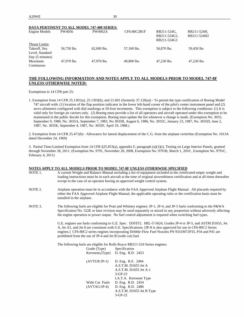
A20WE 30
DATA PERTINENT TO ALL MODEL 747-400 SERIES: Engine Models PW4056 PW4062A CF6-80C2B1F RB211-524G, RB211-524H, RB211-524G2, RB211-524H2 RB211-524G3 Thrust Limits: Takeoff, Sea 56,750 lbs. 62,000 lbs. 57,160 lbs. 56,870 lbs. 59,450 lbs Level, Standard Day (5 minutes) Maximum 47,970 lbs. 47,970 lbs. 49,800 lbs. 47,230 lbs. 47,230 lbs. Continuous THE FOLLOWING INFORMATION AND NOTES APPLY TO ALL MODELS PRIOR TO MODEL 747-8F UNLESS OTHERWISE NOTED: Exemptions to 14 CFR part 25: 1. Exemption from 14 CFR 25.1301(a), 25.1303(b), and 21.601 (formerly 37.120(a)) - To permit the type certification of Boeing Model
747 aircraft with: (1) location of the flap position indicator in the lower left-hand corner of the pilot's center instrument panel and (2) servo altimeters configured with dial markings at 50-foot increments. This exemption is subject to the following conditions: (1) It is valid only for foreign air carriers only. (2) Boeing must provide a list of all operators and aircraft operated under this exemption to be maintained in the public docekt for this exemption. Boeing must update the list whenever a change is made. (Exemption No. 3035, September 9, 1980, No. 3035A, September 7, 1983, No 3035B, August 6, 1986, No. 3035C, January 23, 1987, No. 3035D, June 2, 1987, No. 3035E, September 4, 1987, No. 3035F, April 19, 1988.)
2. Exemption from 14 CFR 25.471(b) - Allowance for lateral displacement of the C.G. from the airplane certerline (Exemption No. 1013A dated December 24, 1969) 3. Partial Time-Limited Exemption from 14 CFR §25.853(a), appendix F, paragraph (a)(1)(i), Testing on Large Interior Panels, granted through November 28, 2011. (Exemption No. 9791, November 28, 2008, Exemption No. 9791B, March 1, 2010 , Exemption No. 9791C, February 4, 2011) NOTES APPLY TO ALL MODELS PRIOR TO MODEL 747-8F UNLESS OTHERWISE SPECIFIED NOTE 1. A current Weight and Balance Manual including a list of equipment included in the certificated empty weight and
loading instructions must be in each aircraft at the time of original airworthiness certification and at all times thereafter except in the case of an operator having an approved weight control system.
NOTE 2. Airplane operation must be in accordance with the FAA Approved Airplane Flight Manual. All placards required by
either the FAA Approved Airplane Flight Manual, the applicable operating rules or the certification basis must be installed in the airplane.
NOTE 3. The following fuels are eligible for Pratt and Whitney engines: JP-1, JP-4, and JP-5 fuels conforming to the P&WA
Specification No. 522E or later revision may be used separately or mixed in any proportion without adversely affecting the engine operation or power output. No fuel control adjustment is required when switching fuel types.
G.E. engines use fuels conforming to G.E. Spec. D50TF2. MIL-T-5624, Grades JP-4 or JP-5, and ASTM D1655, Jet
A, Jet A1, and Jet 8 are consistent with G.E. Specifications. [JP-8 is also approved for use in CF6-80C2 Series engines.] CF6-80C2 series engines incorporating Dribble Flow Fuel Nozzles PN 9331M72P33, P34 and P41 are prohibited from the use of JP-4 and Jet B (wide cut) fuel.
The following fuels are eligible for Rolls Royce RB211-524 Series engines: Grade (Type) Specification Kerosene,(Type) D. Eng. R.D. 2453 (AVTUR:JP-1) D. Eng. R.E. 2494 A.S.T.M. D1655 Jet A A.S.T.M. D1655 Jet A-1 3-GP-23 I.A.T.A. Kerosene Type Wide Cut Fuels D. Eng. R.D. 2454 (AVTAG:JP-4) D. Eng. R.D. 2486 A.S.T.M. D1655 Jet B Type 3-GP-22
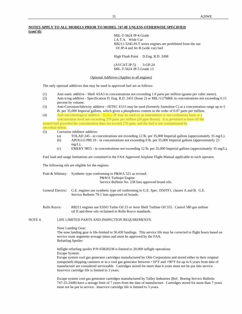
31 A20WE
NOTES APPLY TO ALL MODELS PRIOR TO MODEL 747-8F UNLESS OTHERWISE SPECIFIED (cont’d): MIL-T-5624 JP-4 Grade I.A.T.A. Wide Cut RB211-524G/H-T series engines are prohibited from the use Of JP-4 and Jet B (wide cut) fuel High Flash Point D.Eng. R.D. 2498 (AVCAT:JP-5) 3-GP-24 MIL-T-5624 JP-5 Grade 13 Optional Additives (Applies to all engines) The only optional additives that may be used in approved fuel are as follows: (1) Anti-static additive - Shell ASA3 in concentrations not exceeding 1.0 parts per million (grams per cubic meter). (2) Anti-icing additive - Specification D. Eng. R.D. 2451 (Issue 2) or MIL/1/27686E in concentrations not exceeding 0.15
percent by volume. (3) Anti-Corrosion/lubricity additive - HITEC E515 may be used (formerly Santolene C) at a concentration range up to 5
lb. per 35,000 Imperial gallons, which gives a phosphorus content in the order of 0.07 parts per million. (4) Anti-microbiological additive - Biobor JF may be used on an intermittent or not-continuous basis at a concentration level not exceeding 270 parts per million (20 ppm Boron). It is permitted to burn off the treated fuel provided the concentration does not exceed 270 ppm, and the fuel is not contaminated by microbial debris. (5) Corrosion inhibitor additive: (a) TOLAD 245 - in concentrations not exceeding 12 lb. per 35,000 Imperial gallons (approximately 35 mg/L). (b) APOLLO PRI 19 - in concentrations not exceeding 8 lb. per 35,000 Imperial gallons (approximately 23
mg/L). (c) EMERY 9855 - in concentrations not exceeding 12 lb. per 35,000 Imperial gallons (approximately 35 mg/L). Fuel load and usage limitations are contained in the FAA Approved Airplane Flight Manual applicable to each operator. The following oils are eligible for the engines: Pratt & Whitney: Synthetic type conforming to P&WA 521 as revised. P&WA Turbojet Engine Service Bulletin No. 238 lists approved brand oils. General Electric: G.E. engines use synthetic type oil conforming to G.E. Spec. D50TF1, classes A and B. G.E. Service Bulletin 79-1 lists approved oil brands. Rolls Royce: RB211 engines use ESSO Turbo Oil 25 or Aero Shell Turbine Oil 555. Castrol 580 gas turbine oil II and these oils reclaimed to Rolls Royce standards. NOTE 4. LIFE LIMITED PARTS AND INSPECTION REQUIREMENTS: Nose Landing Gear: The nose landing gear is life-limited to 50,430 landings. This service life may be corrected to flight hours based on
service route segments average times and must be approved by the FAA. Refueling Spoiler: Inflight refueling spoiler P/N 65B20238 is limited to 20,000 inflight operations. Escape System: Escape system cool gas generator cartridges manufactured by Olin Corporation and stored either in their original
(unopened) shipping canisters or in a cool gas generator between +10F and +90F for up to 6 years from date of manufacture are considered serviceable. Cartridges stored for more than 6 years must not be put into service. Inservice cartridge life is limited to 3 years.
Escape system cool gas generator cartridges manufactured by Talley Industries (Ref. Boeing Service Bulletin
747-25-2448) have a storage limit of 7 years from the date of manufacture. Cartridges stored for more than 7 years must not be put in service. Inservice cartridge life is limited to 3 years.
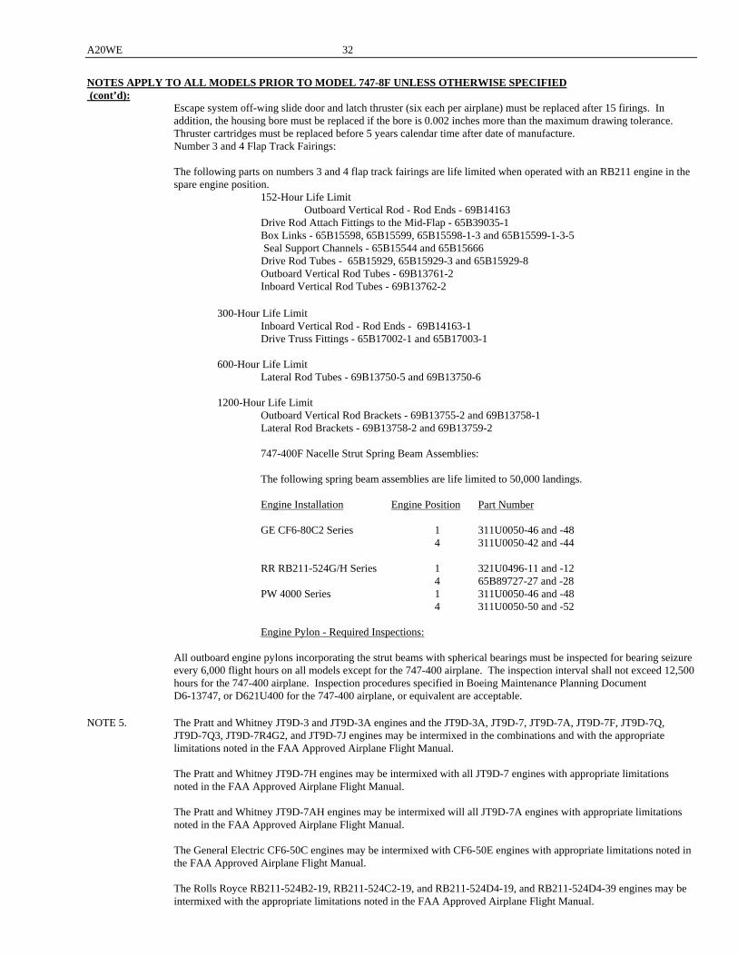
A20WE 32
NOTES APPLY TO ALL MODELS PRIOR TO MODEL 747-8F UNLESS OTHERWISE SPECIFIED (cont’d): Escape system off-wing slide door and latch thruster (six each per airplane) must be replaced after 15 firings. In
addition, the housing bore must be replaced if the bore is 0.002 inches more than the maximum drawing tolerance. Thruster cartridges must be replaced before 5 years calendar time after date of manufacture.
Number 3 and 4 Flap Track Fairings: The following parts on numbers 3 and 4 flap track fairings are life limited when operated with an RB211 engine in the spare engine position.
152-Hour Life Limit Outboard Vertical Rod - Rod Ends - 69B14163 Drive Rod Attach Fittings to the Mid-Flap - 65B39035-1 Box Links - 65B15598, 65B15599, 65B15598-1-3 and 65B15599-1-3-5 Seal Support Channels - 65B15544 and 65B15666 Drive Rod Tubes - 65B15929, 65B15929-3 and 65B15929-8 Outboard Vertical Rod Tubes - 69B13761-2 Inboard Vertical Rod Tubes - 69B13762-2 300-Hour Life Limit Inboard Vertical Rod - Rod Ends - 69B14163-1 Drive Truss Fittings - 65B17002-1 and 65B17003-1 600-Hour Life Limit Lateral Rod Tubes - 69B13750-5 and 69B13750-6 1200-Hour Life Limit Outboard Vertical Rod Brackets - 69B13755-2 and 69B13758-1 Lateral Rod Brackets - 69B13758-2 and 69B13759-2 747-400F Nacelle Strut Spring Beam Assemblies: The following spring beam assemblies are life limited to 50,000 landings. Engine Installation Engine Position Part Number GE CF6-80C2 Series 1 311U0050-46 and -48 4 311U0050-42 and -44 RR RB211-524G/H Series 1 321U0496-11 and -12 4 65B89727-27 and -28 PW 4000 Series 1 311U0050-46 and -48 4 311U0050-50 and -52 Engine Pylon - Required Inspections: All outboard engine pylons incorporating the strut beams with spherical bearings must be inspected for bearing seizure
every 6,000 flight hours on all models except for the 747-400 airplane. The inspection interval shall not exceed 12,500 hours for the 747-400 airplane. Inspection procedures specified in Boeing Maintenance Planning Document D6-13747, or D621U400 for the 747-400 airplane, or equivalent are acceptable.
NOTE 5. The Pratt and Whitney JT9D-3 and JT9D-3A engines and the JT9D-3A, JT9D-7, JT9D-7A, JT9D-7F, JT9D-7Q,
JT9D-7Q3, JT9D-7R4G2, and JT9D-7J engines may be intermixed in the combinations and with the appropriate limitations noted in the FAA Approved Airplane Flight Manual.
The Pratt and Whitney JT9D-7H engines may be intermixed with all JT9D-7 engines with appropriate limitations
noted in the FAA Approved Airplane Flight Manual. The Pratt and Whitney JT9D-7AH engines may be intermixed will all JT9D-7A engines with appropriate limitations
noted in the FAA Approved Airplane Flight Manual. The General Electric CF6-50C engines may be intermixed with CF6-50E engines with appropriate limitations noted in
the FAA Approved Airplane Flight Manual.
The Rolls Royce RB211-524B2-19, RB211-524C2-19, and RB211-524D4-19, and RB211-524D4-39 engines may be intermixed with the appropriate limitations noted in the FAA Approved Airplane Flight Manual.
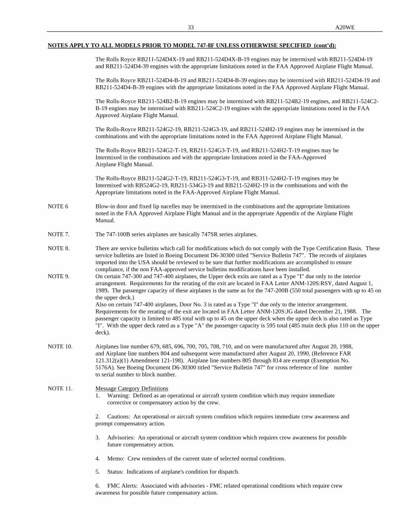
33 A20WE
NOTES APPLY TO ALL MODELS PRIOR TO MODEL 747-8F UNLESS OTHERWISE SPECIFIED (cont’d): The Rolls Royce RB211-524D4X-19 and RB211-524D4X-B-19 engines may be intermixed with RB211-524D4-19
and RB211-524D4-39 engines with the appropriate limitations noted in the FAA Approved Airplane Flight Manual. The Rolls Royce RB211-524D4-B-19 and RB211-524D4-B-39 engines may be intermixed with RB211-524D4-19 and
RB211-524D4-B-39 engines with the appropriate limitations noted in the FAA Approved Airplane Flight Manual.
The Rolls-Royce RB211-524B2-B-19 engines may be intermixed with RB211-524B2-19 engines, and RB211-524C2-B-19 engines may be intermixed with RB211-524C2-19 engines with the appropriate limitations noted in the FAA Approved Airplane Flight Manual. The Rolls-Royce RB211-524G2-19, RB211-524G3-19, and RB211-524H2-19 engines may be intermixed in the combinations and with the appropriate limitations noted in the FAA Approved Airplane Flight Manual.
The Rolls-Royce RB211-524G2-T-19, RB211-524G3-T-19, and RB211-524H2-T-19 engines may be Intermixed in the combinations and with the appropriate limitations noted in the FAA-Approved Airplane Flight Manual. The Rolls-Royce RB211-524G2-T-19, RB211-524G3-T-19, and RB311-524H2-T-19 engines may be Intermixed with RB524G2-19, RB211-534G3-19 and RB211-524H2-19 in the combinations and with the Appropriate limitations noted in the FAA-Approved Airplane Flight Manual. NOTE 6 Blow-in door and fixed lip nacelles may be intermixed in the combinations and the appropriate limitations noted in the FAA Approved Airplane Flight Manual and in the appropriate Appendix of the Airplane Flight Manual. NOTE 7. The 747-100B series airplanes are basically 747SR series airplanes. NOTE 8. There are service bulletins which call for modifications which do not comply with the Type Certification Basis. These
service bulletins are listed in Boeing Document D6-30300 titled "Service Bulletin 747". The records of airplanes imported into the USA should be reviewed to be sure that further modifications are accomplished to ensure compliance, if the non FAA-approved service bulletins modifications have been installed.
NOTE 9. On certain 747-300 and 747-400 airplanes, the Upper deck exits are rated as a Type "I" due only to the interior arrangement. Requirements for the rerating of the exit are located in FAA Letter ANM-120S:RSY, dated August 1, 1989. The passenger capacity of these airplanes is the same as for the 747-200B (550 total passengers with up to 45 on the upper deck.)
Also on certain 747-400 airplanes, Door No. 3 is rated as a Type "I" due only to the interior arrangement. Requirements for the rerating of the exit are located in FAA Letter ANM-120S:JG dated December 21, 1988. The passenger capacity is limited to 485 total with up to 45 on the upper deck when the upper deck is also rated as Type "I". With the upper deck rated as a Type "A" the passenger capacity is 595 total (485 main deck plus 110 on the upper deck).
NOTE 10. Airplanes line number 679, 685, 696, 700, 705, 708, 710, and on were manufactured after August 20, 1988, and Airplane line numbers 804 and subsequent were manufactured after August 20, 1990, (Reference FAR 121.312(a)(1) Amendment 121-198). Airplane line numbers 805 through 814 are exempt (Exemption No. 5176A). See Boeing Document D6-30300 titled "Service Bulletin 747" for cross reference of line number to serial number to block number. NOTE 11. Message Category Definitions 1. Warning: Defined as an operational or aircraft system condition which may require immediate corrective or compensatory action by the crew. 2. Cautions: An operational or aircraft system condition which requires immediate crew awareness and prompt compensatory action. 3. Advisories: An operational or aircraft system condition which requires crew awareness for possible future compensatory action. 4. Memo: Crew reminders of the current state of selected normal conditions. 5. Status: Indications of airplane's condition for dispatch. 6. FMC Alerts: Associated with advisories - FMC related operational conditions which require crew awareness for possible future compensatory action.
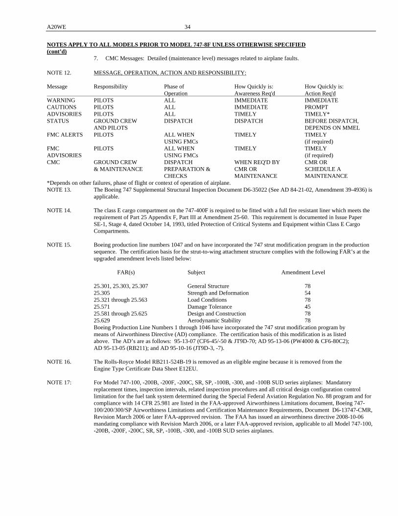
A20WE 34
NOTES APPLY TO ALL MODELS PRIOR TO MODEL 747-8F UNLESS OTHERWISE SPECIFIED (cont’d) 7. CMC Messages: Detailed (maintenance level) messages related to airplane faults. NOTE 12. MESSAGE, OPERATION, ACTION AND RESPONSIBILITY: Message Responsibility Phase of How Quickly is: How Quickly is: Operation Awareness Req'd Action Req'd WARNING PILOTS ALL IMMEDIATE IMMEDIATE CAUTIONS PILOTS ALL IMMEDIATE PROMPT ADVISORIES PILOTS ALL TIMELY TIMELY* STATUS GROUND CREW DISPATCH DISPATCH BEFORE DISPATCH, AND PILOTS DEPENDS ON MMEL FMC ALERTS PILOTS ALL WHEN TIMELY TIMELY USING FMCs (if required) FMC PILOTS ALL WHEN TIMELY TIMELY ADVISORIES USING FMCs (if required) CMC GROUND CREW DISPATCH WHEN REQ'D BY CMR OR & MAINTENANCE PREPARATION & CMR OR SCHEDULE A CHECKS MAINTENANCE MAINTENANCE *Depends on other failures, phase of flight or context of operation of airplane. NOTE 13. The Boeing 747 Supplemental Structural Inspection Document D6-35022 (See AD 84-21-02, Amendment 39-4936) is
applicable. NOTE 14. The class E cargo compartment on the 747-400F is required to be fitted with a full fire resistant liner which meets the requirement of Part 25 Appendix F, Part III at Amendment 25-60. This requirement is documented in Issue Paper SE-1, Stage 4, dated October 14, 1993, titled Protection of Critical Systems and Equipment within Class E Cargo Compartments. NOTE 15. Boeing production line numbers 1047 and on have incorporated the 747 strut modification program in the production sequence. The certification basis for the strut-to-wing attachment structure complies with the following FAR’s at the
upgraded amendment levels listed below: FAR(s) Subject Amendment Level 25.301, 25.303, 25.307 General Structure 78 25.305 Strength and Deformation 54 25.321 through 25.563 Load Conditions 78 25.571 Damage Tolerance 45 25.581 through 25.625 Design and Construction 78 25.629 Aerodynamic Stability 78 Boeing Production Line Numbers 1 through 1046 have incorporated the 747 strut modification program by means of Airworthiness Directive (AD) compliance. The certification basis of this modification is as listed above. The AD’s are as follows: 95-13-07 (CF6-45/-50 & JT9D-70; AD 95-13-06 (PW4000 & CF6-80C2); AD 95-13-05 (RB211); and AD 95-10-16 (JT9D-3, -7). NOTE 16. The Rolls-Royce Model RB211-524B-19 is removed as an eligible engine because it is removed from the Engine Type Certificate Data Sheet E12EU. NOTE 17: For Model 747-100, -200B, -200F, -200C, SR, SP, -100B, -300, and -100B SUD series airplanes: Mandatory
replacement times, inspection intervals, related inspection procedures and all critical design configuration control limitation for the fuel tank system determined during the Special Federal Aviation Regulation No. 88 program and for compliance with 14 CFR 25.981 are listed in the FAA-approved Airworthiness Limitations document, Boeing 747-100/200/300/SP Airworthiness Limitations and Certification Maintenance Requirements, Document D6-13747-CMR, Revision March 2006 or later FAA-approved revision. The FAA has issued an airworthiness directive 2008-10-06 mandating compliance with Revision March 2006, or a later FAA-approved revision, applicable to all Model 747-100, -200B, -200F, -200C, SR, SP, -100B, -300, and -100B SUD series airplanes.

35 A20WE
NOTES APPLY TO ALL MODELS PRIOR TO MODEL 747-8F UNLESS OTHERWISE SPECIFIED (cont’d) NOTE 18: For Model 747-400, -400D, and -400F series airplanes: Mandatory replacement times, inspection intervals, related
inspection procedures and all critical design configuration control limitation for the fuel tank system determined during the Special Federal Aviation Regulation No. 88 program and for compliance with 14 CFR 25.981 and Special Conditions No. 25.285-SC are listed in the FAA-approved Airworthiness Limitations and Certification Maintenance Requirement, Section 9, of Boeing 747-400 Maintenance Planning Data Document D621U400-9, Revision August 2005 or later FAA-approved revision. All Model 747-400, -400D, and -400F series airplanes, production line number 1377 and on, must comply with Revision March 2006, or a later FAA-approved revision. The FAA is planning to issue an airworthiness directive mandating compliance with Revision March 2006, or a later FAA-approved revision, applicable to all Model 747-400, -400D, and -400F series airplanes with production numbers lower than 1377
XV. Model 747-8F (Approved August 19, 2011) Transport Category The 747-8F series is based on the model 747-400F series aircraft with design changes to the empennage, fuselage, landing gear, wings, engines, fuel systems, and other aircraft systems as defined in the certification basis within this section. The certification basis for areas unaffected by this change from the 747-400F series aircraft will remain certified at the 14 CFR Part 25 Amendment level of their original certification date. Engines: 4 General Electric Turbofan Engines Model: GEnx-2B67, GEnx-2B67B (Engine Type Certificate No. E00078NE) Fuel: General Electric Turbofan Engines Fuels conforming to: ASTM D-1655 grades Jet-A and Jet A-1 MIL-T-5624 grade JP-5 MIL-T-83133 grade JP-8 are acceptable Fuels produced to other specifications and having properties meeting the requirements of the above specifications are acceptable.
The fuel and any fuel additives must conform to the relevant Engine Operating Instructions. Engine Limits: General Electric Turbofan Engines See the FAA approved Airplane Flight Manual for engine ratings. Airspeed Limits: VMO/MMO = 365/0.9 (KCAS) See the appropriate FAA Approved Airplane Flight Manual for other
airspeed limits C.G. Range: See the appropriate FAA Approved Airplane Flight Manual Empty Weight C.G.: See the appropriate FAA Approved Airplane Flight Manual Datum: See Weights and Balance Manual Leveling Means: See FAA Approve Airplane Flight Manual Maximum Weights: See the appropriate FAA approved Airplane Flight Manual Minimum Crew: Two (2) persons: pilot and copilot Number of Seats: Maximum of eight (8) persons including the flight crew per exemption 9793C and limitations outlined in the
FAA approved Airplane Flight Manual Maximum Compartment: See the appropriate Weight and Balance Control Manual Weights Fuel Capacity: See the appropriate Weight and Balance Control Manual Oil Capacity: See the appropriate Weight and Balance Control Manual Maximum Operating: 42,100 Altitude
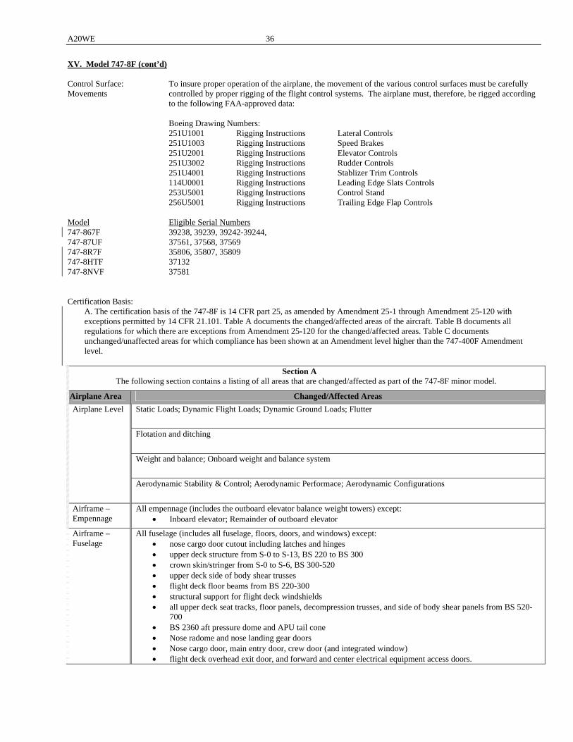
A20WE 36
XV. Model 747-8F (cont’d) Control Surface: To insure proper operation of the airplane, the movement of the various control surfaces must be carefully Movements controlled by proper rigging of the flight control systems. The airplane must, therefore, be rigged according
to the following FAA-approved data: Boeing Drawing Numbers: 251U1001 Rigging Instructions Lateral Controls 251U1003 Rigging Instructions Speed Brakes 251U2001 Rigging Instructions Elevator Controls 251U3002 Rigging Instructions Rudder Controls 251U4001 Rigging Instructions Stablizer Trim Controls 114U0001 Rigging Instructions Leading Edge Slats Controls 253U5001 Rigging Instructions Control Stand 256U5001 Rigging Instructions Trailing Edge Flap Controls Model Eligible Serial Numbers 747-867F 39238, 39239, 39242-39244, 747-87UF 37561, 37568, 37569 747-8R7F 35806, 35807, 35809 747-8HTF 37132 747-8NVF 37581 Certification Basis: A. The certification basis of the 747-8F is 14 CFR part 25, as amended by Amendment 25-1 through Amendment 25-120 with
exceptions permitted by 14 CFR 21.101. Table A documents the changed/affected areas of the aircraft. Table B documents all regulations for which there are exceptions from Amendment 25-120 for the changed/affected areas. Table C documents unchanged/unaffected areas for which compliance has been shown at an Amendment level higher than the 747-400F Amendment level.
Section A
The following section contains a listing of all areas that are changed/affected as part of the 747-8F minor model.
Airplane Area Changed/Affected Areas
Static Loads; Dynamic Flight Loads; Dynamic Ground Loads; Flutter
Flotation and ditching
Weight and balance; Onboard weight and balance system
Airplane Level
Aerodynamic Stability & Control; Aerodynamic Performace; Aerodynamic Configurations
Airframe – Empennage
All empennage (includes the outboard elevator balance weight towers) except: Inboard elevator; Remainder of outboard elevator
Airframe – Fuselage
All fuselage (includes all fuselage, floors, doors, and windows) except: nose cargo door cutout including latches and hinges upper deck structure from S-0 to S-13, BS 220 to BS 300 crown skin/stringer from S-0 to S-6, BS 300-520 upper deck side of body shear trusses flight deck floor beams from BS 220-300 structural support for flight deck windshields all upper deck seat tracks, floor panels, decompression trusses, and side of body shear panels from BS 520-
700 BS 2360 aft pressure dome and APU tail cone Nose radome and nose landing gear doors Nose cargo door, main entry door, crew door (and integrated window) flight deck overhead exit door, and forward and center electrical equipment access doors.
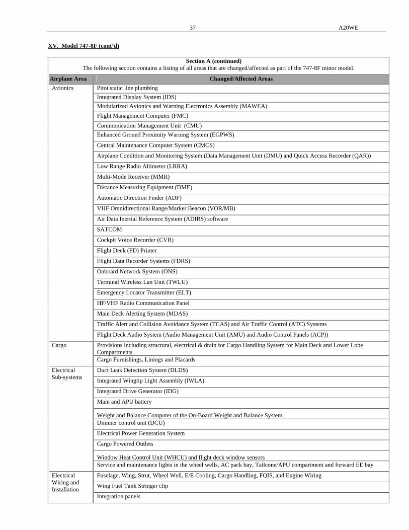
37 A20WE
XV. Model 747-8F (cont’d)
Section A (continued) The following section contains a listing of all areas that are changed/affected as part of the 747-8F minor model.
Airplane Area Changed/Affected Areas
Pitot static line plumbing
Integrated Display System (IDS)
Modularized Avionics and Warning Electronics Assembly (MAWEA)
Flight Management Computer (FMC)
Communication Management Unit (CMU)
Enhanced Ground Proximity Warning System (EGPWS)
Central Maintenance Computer System (CMCS)
Airplane Condition and Monitoring System (Data Management Unit (DMU) and Quick Access Recorder (QAR))
Low Range Radio Altimeter (LRRA)
Multi-Mode Receiver (MMR)
Distance Measuring Equipment (DME)
Automatic Direction Finder (ADF)
VHF Omnidirectional Range/Marker Beacon (VOR/MB)
Air Data Inertial Reference System (ADIRS) software
SATCOM
Cockpit Voice Recorder (CVR)
Flight Deck (FD) Printer
Flight Data Recorder Systems (FDRS)
Onboard Network System (ONS)
Terminal Wireless Lan Unit (TWLU)
Emergency Locator Transmitter (ELT)
HF/VHF Radio Communication Panel
Main Deck Alerting System (MDAS)
Traffic Alert and Collision Avoidance System (TCAS) and Air Traffic Control (ATC) Systems
Avionics
Flight Deck Audio System (Audio Management Unit (AMU) and Audio Control Panels (ACP))
Provisions including structural, electrical & drain for Cargo Handling System for Main Deck and Lower Lobe Compartments
Cargo
Cargo Furnishings, Linings and Placards
Duct Leak Detection System (DLDS)
Integrated Wingtip Light Assembly (IWLA)
Integrated Drive Generator (IDG)
Main and APU battery
Weight and Balance Computer of the On-Board Weight and Balance System Dimmer control unit (DCU)
Electrical Power Generation System
Cargo Powered Outlets
Window Heat Control Unit (WHCU) and flight deck window sensors
Electrical Sub-systems
Service and maintenance lights in the wheel wells, AC pack bay, Tailcone/APU compartment and forward EE bay
Fuselage, Wing, Strut, Wheel Well, E/E Cooling, Cargo Handling, FQIS, and Engine Wiring
Wing Fuel Tank Stringer clip
Electrical Wiring and Installation
Integration panels
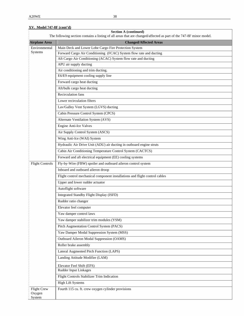
A20WE 38
XV. Model 747-8F (cont’d) Section A (continued)
The following section contains a listing of all areas that are changed/affected as part of the 747-8F minor model.
Airplane Area Changed/Affected Areas
Main Deck and Lower Lobe Cargo Fire Protection System
Forward Cargo Air Conditioning (FCAC) System flow rate and ducting
Aft Cargo Air Conditioning (ACAC) System flow rate and ducting
APU air supply ducting
Air conditioning and trim ducting.
E6/E9 equipment cooling supply line
Forward cargo heat ducting
Aft/bulk cargo heat ducting
Recirculation fans
Lower recirculation filters
Lav/Galley Vent System (LGVS) ducting
Cabin Pressure Control System (CPCS)
Alternate Ventilation System (AVS)
Engine Anti-Ice Valves
Air Supply Control System (ASCS)
Wing Anti-Ice (WAI) System
Hydraulic Air Drive Unit (ADU) air ducting in outboard engine struts
Cabin Air Conditioning Temperature Control System (CACTCS)
Environmental Systems
Forward and aft electrical equipment (EE) cooling systems
Fly-by-Wire (FBW) spoiler and outboard aileron control system
Inboard and outboard aileron droop
Flight control mechanical component installations and flight control cables
Upper and lower rudder actuator
Autoflight software
Integrated Standby Flight Display (ISFD)
Rudder ratio changer
Elevator feel computer
Yaw damper control laws
Yaw damper stabilizer trim modules (YSM)
Pitch Augmentation Control System (PACS)
Yaw Damper Modal Suppression System (MSS)
Outboard Aileron Modal Suppression (OAMS)
Roller brake assembly
Lateral Augmented Pitch Function (LAPS)
Landing Attitude Modifier (LAM)
Elevator Feel Shift (EFS) Rudder Input Linkages
Flight Controls Stabilizer Trim Indication
Flight Controls
High Lift Systems
Flight Crew Oxygen System
Fourth 115 cu. ft. crew oxygen cylinder provisions
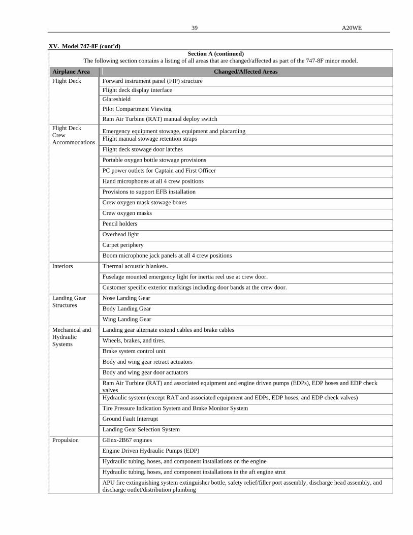
39 A20WE
XV. Model 747-8F (cont’d)
Section A (continued) The following section contains a listing of all areas that are changed/affected as part of the 747-8F minor model.
Airplane Area Changed/Affected Areas
Forward instrument panel (FIP) structure
Flight deck display interface
Glareshield
Pilot Compartment Viewing
Flight Deck
Ram Air Turbine (RAT) manual deploy switch
Emergency equipment stowage, equipment and placarding Flight manual stowage retention straps
Flight deck stowage door latches
Portable oxygen bottle stowage provisions
PC power outlets for Captain and First Officer
Hand microphones at all 4 crew positions
Provisions to support EFB installation
Crew oxygen mask stowage boxes
Crew oxygen masks
Pencil holders
Overhead light
Carpet periphery
Flight Deck Crew Accommodations
Boom microphone jack panels at all 4 crew positions
Thermal acoustic blankets.
Fuselage mounted emergency light for inertia reel use at crew door.
Interiors
Customer specific exterior markings including door bands at the crew door.
Nose Landing Gear
Body Landing Gear
Landing Gear Structures
Wing Landing Gear
Landing gear alternate extend cables and brake cables
Wheels, brakes, and tires.
Brake system control unit
Body and wing gear retract actuators
Body and wing gear door actuators
Ram Air Turbine (RAT) and associated equipment and engine driven pumps (EDPs), EDP hoses and EDP check valves Hydraulic system (except RAT and associated equipment and EDPs, EDP hoses, and EDP check valves)
Tire Pressure Indication System and Brake Monitor System
Ground Fault Interrupt
Mechanical and Hydraulic Systems
Landing Gear Selection System
GEnx-2B67 engines
Engine Driven Hydraulic Pumps (EDP)
Hydraulic tubing, hoses, and component installations on the engine
Hydraulic tubing, hoses, and component installations in the aft engine strut
Propulsion
APU fire extinguishing system extinguisher bottle, safety relief/filler port assembly, discharge head assembly, and discharge outlet/distribution plumbing

A20WE 40
XV. Model 747-8F (cont’d) Section A (continued)
The following section contains a listing of all areas that are changed/affected as part of the 747-8F minor model.
Airplane Area Changed/Affected Areas
APU, APU Controls and APU Installation
Engine Controls
Thrust Reverser Systems Propulsion – Electrical Sub-systems
APU power feeder
Jettison System
Auxiliary Power Unit (APU) Feed System line, pumps and plumbing
Reserve Tank Transfer System
Fuel System Scavenge
Fuel tank structure
Fuel Feed System
Fuel Vent System
Fuel Management System
Refuel/Defuel System
Fuel Quantity Indicating System (FQIS) and fuel level sensing
Fuel sump system drain valves
Propulsion -Fuels
Nitrogen Generation System (NGS)
Propulsion – Structures
Strut, nacelle, thrust reverser, inlet, exhaust, and systems
Emergency Evacuation Harnesses
Ceilings
Closet
Seats
PSUs and general lighting
Sidewall linings
Partition between closet and RH sidewall
Placarding
Floor coverings
Crew bunk mattresses
Crew bunk area smoke penetration seals
Ladder Enclosure to Upper Deck Supernumerary Area Smoke Penetration Seals
Lavatory
Galley
Portable oxygen cylinders and full face masks for main deck cargo access
Placarding in supernumerary area for main deck cargo access
Emergency equipment stowage, equipment and placarding
Supernumerary Area
Lighted Signs and Overhead emergency exit signs
Oxygen boxes
Portable oxygen bottles
Supernumerary Oxygen System
Composite Cylinders
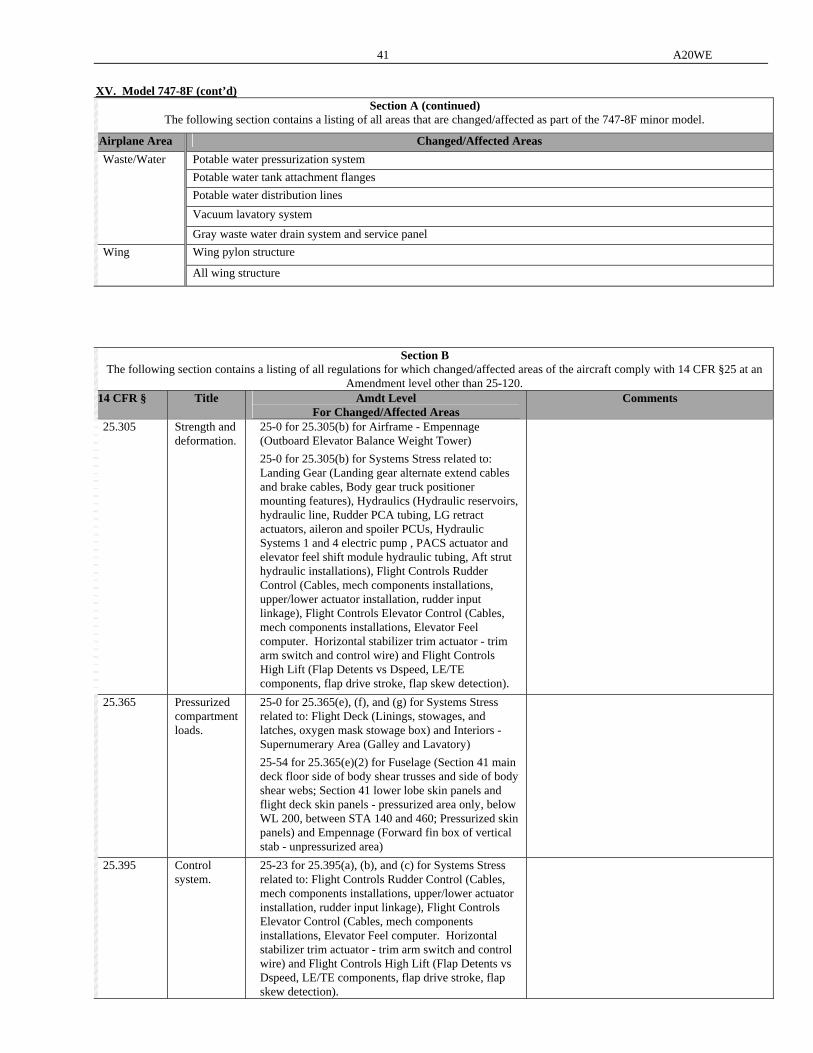
41 A20WE
XV. Model 747-8F (cont’d)
Section A (continued) The following section contains a listing of all areas that are changed/affected as part of the 747-8F minor model.
Airplane Area Changed/Affected Areas
Potable water pressurization system
Potable water tank attachment flanges
Potable water distribution lines
Vacuum lavatory system
Waste/Water
Gray waste water drain system and service panel
Wing pylon structure Wing
All wing structure
Section B The following section contains a listing of all regulations for which changed/affected areas of the aircraft comply with 14 CFR §25 at an
Amendment level other than 25-120. 14 CFR § Title Amdt Level
For Changed/Affected Areas Comments
25.305 Strength and deformation.
25-0 for 25.305(b) for Airframe - Empennage (Outboard Elevator Balance Weight Tower)
25-0 for 25.305(b) for Systems Stress related to: Landing Gear (Landing gear alternate extend cables and brake cables, Body gear truck positioner mounting features), Hydraulics (Hydraulic reservoirs, hydraulic line, Rudder PCA tubing, LG retract actuators, aileron and spoiler PCUs, Hydraulic Systems 1 and 4 electric pump , PACS actuator and elevator feel shift module hydraulic tubing, Aft strut hydraulic installations), Flight Controls Rudder Control (Cables, mech components installations, upper/lower actuator installation, rudder input linkage), Flight Controls Elevator Control (Cables, mech components installations, Elevator Feel computer. Horizontal stabilizer trim actuator - trim arm switch and control wire) and Flight Controls High Lift (Flap Detents vs Dspeed, LE/TE components, flap drive stroke, flap skew detection).
25.365 Pressurized compartment loads.
25-0 for 25.365(e), (f), and (g) for Systems Stress related to: Flight Deck (Linings, stowages, and latches, oxygen mask stowage box) and Interiors - Supernumerary Area (Galley and Lavatory)
25-54 for 25.365(e)(2) for Fuselage (Section 41 main deck floor side of body shear trusses and side of body shear webs; Section 41 lower lobe skin panels and flight deck skin panels - pressurized area only, below WL 200, between STA 140 and 460; Pressurized skin panels) and Empennage (Forward fin box of vertical stab - unpressurized area)
25.395 Control system.
25-23 for 25.395(a), (b), and (c) for Systems Stress related to: Flight Controls Rudder Control (Cables, mech components installations, upper/lower actuator installation, rudder input linkage), Flight Controls Elevator Control (Cables, mech components installations, Elevator Feel computer. Horizontal stabilizer trim actuator - trim arm switch and control wire) and Flight Controls High Lift (Flap Detents vs Dspeed, LE/TE components, flap drive stroke, flap skew detection).

A20WE 42
XV. Model 747-8F (cont’d) Section B (continued)
The following section contains a listing of all regulations for which changed/affected areas of the aircraft comply with 14 CFR §25 at an Amendment level other than 25-120.
14 CFR § Title Amdt Level For Changed/Affected Areas
Comments
25.397 Control system loads.
25-38 for 25.397 for Systems Stress related to: Flight Controls Rudder Control (Cables, mech components installations, upper/lower actuator installation, rudder input linkage), Flight Controls Elevator Control (Cables, mech components installations, Elevator Feel computer. Horizontal stabilizer trim actuator - trim arm switch and control wire) and Flight Controls High Lift (Flap Detents vs Dspeed, LE/TE components, flap drive stroke, flap skew detection).
25.415 Ground gust conditions.
25-0 for 25.415 for Systems Stress related to: Flight Controls Rudder Control (Cables, mech components installations, upper/lower actuator installation, rudder input linkage), Flight Controls Elevator Control (Cables, mech components installations, Elevator Feel computer. Horizontal stabilizer trim actuator - trim arm switch and control wire) and Flight Controls High Lift (Flap Detents vs Dspeed, LE/TE components, flap drive stroke, flap skew detection).
25.561 General. N/A for 25.561(c)(1)(ii) for Airframe – Fuselage/Floor Structures (Section 46 floor beams and frames)
25.562 Emergency landing dynamic conditions.
N/A for 25.562 for Flight Deck - Flight Deck Seats and Interiors – Supernumerary Area
25.571 Damage-tolerance and fatigue evaluation of structure.
25-0 for 25.571(a) and (c) for Systems Stress related to: Flight Controls Rudder Control (Cables, mech components installations, upper/lower actuator installation, rudder input linkage), Flight Controls Elevator Control (Cables, mech components installations, Elevator Feel computer. Horizontal stabilizer trim actuator - trim arm switch and control wire) and Flight Controls High Lift (Flap Detents vs Dspeed, LE/TE components, flap drive stroke, flap skew detection).
25-86 for 25.571(a) and (b) for Systems Stress related to Flight Controls – Lower Rudder Tab Push Rod
25-86 for 25.571(a) and (b) for Fuselage (Section 41 upper deck floor beams BS 320-520; main deck floor side of body shear trusses and side of body shear webs; Section 42 skins BS 520-740 except window belt skin panels; stringers S-0 to S-5 L/R, S-11 to S-17, S-28 to S-33; frames at upper deck floor joint (except new plug frames); crown splice fittings at BS 520 & BS740; upper deck emergency door surround structure; lower lobe cargo door surround structure; upper deck floor stabilization system, lavatory and galley supports, and floor beam to frame connections; main deck floor side of body shear trusses and side of body shear webs; bulk cargo door; Main Deck Side Cargo Door; forward and aft lower lobe cargo doors), Wing, and Empennage (Stabilizer forward torque box and leading edge; fin forward torque box; Outboard Elevator Balance Weight Tower) N/A for 25.571 for Landing Gear (Main Gear)
Compliance to be shown to CFR25.573(a) and (c) Amdt 25-0 in lieu of CFR25.571 Amdt 120 for Landing Gear (Main Gear).
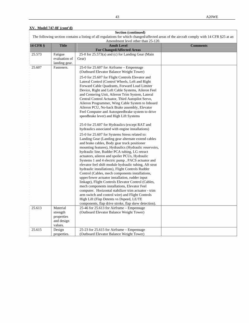
43 A20WE
XV. Model 747-8F (cont’d)
Section (continued) The following section contains a listing of all regulations for which changed/affected areas of the aircraft comply with 14 CFR §25 at an
Amendment level other than 25-120. 14 CFR § Title Amdt Level
For Changed/Affected Areas Comments
25.573 Fatigue evaluation of landing gear.
25-0 for 25.573(a) and (c) for Landing Gear (Main Gear)
25.607 Fasteners. 25-0 for 25.607 for Airframe – Empennage (Outboard Elevator Balance Weight Tower)
25-0 for 25.607 for Flight Controls Elevator and Lateral Control (Control Wheels, Left and Right Forward Cable Quadrants, Forward Load Limiter Device, Right and Left Cable Systems, Aileron Feel and Centering Unit, Aileron Trim System, Lateral Central Control Actuator, Third Autopilot Servo, Aileron Programmer, Wing Cable System to Inboard Aileron PCU, No-back Brake assembly, Elevator Feel Computer and Autospeedbrake system to drive speedbrake lever) and High Lift Systems 25-0 for 25.607 for Hydraulics (except RAT and hydraulics associated with engine installations)
25-0 for 25.607 for Systems Stress related to: Landing Gear (Landing gear alternate extend cables and brake cables, Body gear truck positioner mounting features), Hydraulics (Hydraulic reservoirs, hydraulic line, Rudder PCA tubing, LG retract actuators, aileron and spoiler PCUs, Hydraulic Systems 1 and 4 electric pump , PACS actuator and elevator feel shift module hydraulic tubing, Aft strut hydraulic installations), Flight Controls Rudder Control (Cables, mech components installations, upper/lower actuator installation, rudder input linkage), Flight Controls Elevator Control (Cables, mech components installations, Elevator Feel computer. Horizontal stabilizer trim actuator - trim arm switch and control wire) and Flight Controls High Lift (Flap Detents vs Dspeed, LE/TE components, flap drive stroke, flap skew detection).
25.613 Material strength properties and design values.
25-46 for 25.613 for Airframe – Empennage (Outboard Elevator Balance Weight Tower)
25.615 Design properties.
25-23 for 25.615 for Airframe – Empennage (Outboard Elevator Balance Weight Tower)
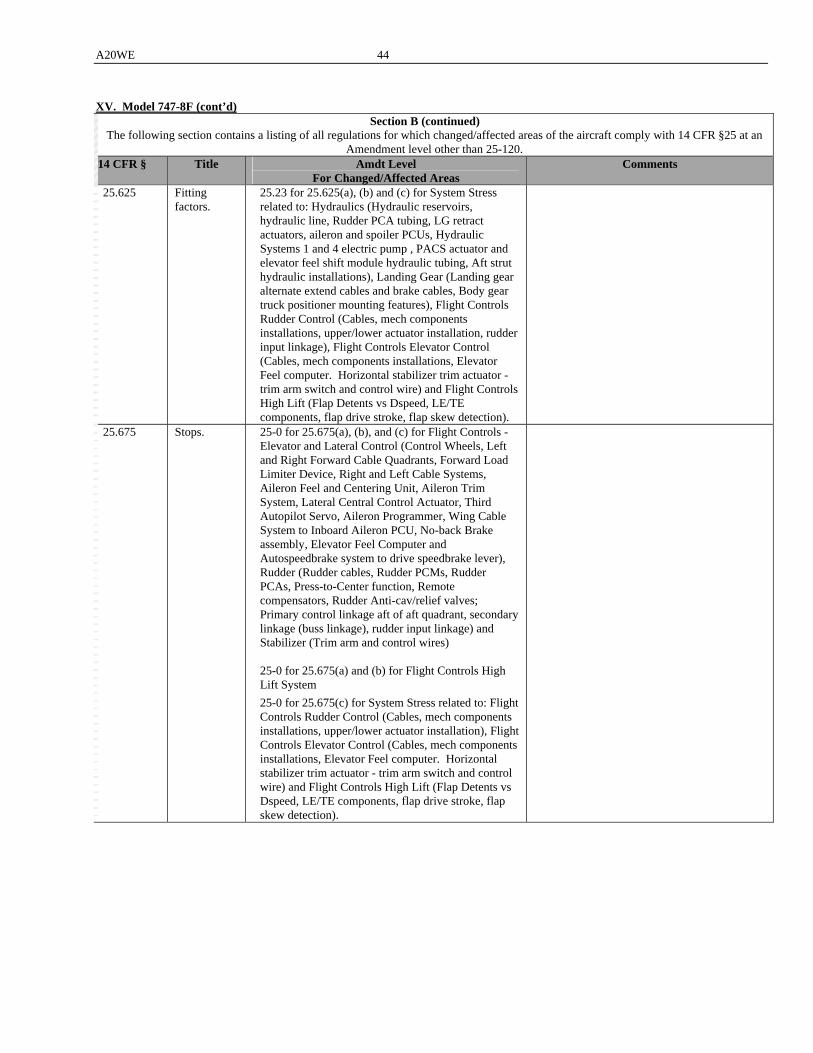
A20WE 44
XV. Model 747-8F (cont’d)
Section B (continued) The following section contains a listing of all regulations for which changed/affected areas of the aircraft comply with 14 CFR §25 at an
Amendment level other than 25-120. 14 CFR § Title Amdt Level
For Changed/Affected Areas Comments
25.625 Fitting factors.
25.23 for 25.625(a), (b) and (c) for System Stress related to: Hydraulics (Hydraulic reservoirs, hydraulic line, Rudder PCA tubing, LG retract actuators, aileron and spoiler PCUs, Hydraulic Systems 1 and 4 electric pump , PACS actuator and elevator feel shift module hydraulic tubing, Aft strut hydraulic installations), Landing Gear (Landing gear alternate extend cables and brake cables, Body gear truck positioner mounting features), Flight Controls Rudder Control (Cables, mech components installations, upper/lower actuator installation, rudder input linkage), Flight Controls Elevator Control (Cables, mech components installations, Elevator Feel computer. Horizontal stabilizer trim actuator - trim arm switch and control wire) and Flight Controls High Lift (Flap Detents vs Dspeed, LE/TE components, flap drive stroke, flap skew detection).
25.675 Stops. 25-0 for 25.675(a), (b), and (c) for Flight Controls - Elevator and Lateral Control (Control Wheels, Left and Right Forward Cable Quadrants, Forward Load Limiter Device, Right and Left Cable Systems, Aileron Feel and Centering Unit, Aileron Trim System, Lateral Central Control Actuator, Third Autopilot Servo, Aileron Programmer, Wing Cable System to Inboard Aileron PCU, No-back Brake assembly, Elevator Feel Computer and Autospeedbrake system to drive speedbrake lever), Rudder (Rudder cables, Rudder PCMs, Rudder PCAs, Press-to-Center function, Remote compensators, Rudder Anti-cav/relief valves; Primary control linkage aft of aft quadrant, secondary linkage (buss linkage), rudder input linkage) and Stabilizer (Trim arm and control wires) 25-0 for 25.675(a) and (b) for Flight Controls High Lift System
25-0 for 25.675(c) for System Stress related to: Flight Controls Rudder Control (Cables, mech components installations, upper/lower actuator installation), Flight Controls Elevator Control (Cables, mech components installations, Elevator Feel computer. Horizontal stabilizer trim actuator - trim arm switch and control wire) and Flight Controls High Lift (Flap Detents vs Dspeed, LE/TE components, flap drive stroke, flap skew detection).
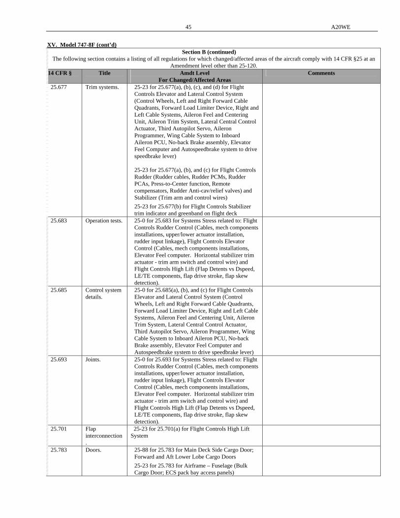
45 A20WE
XV. Model 747-8F (cont’d)
Section B (continued) The following section contains a listing of all regulations for which changed/affected areas of the aircraft comply with 14 CFR §25 at an
Amendment level other than 25-120. 14 CFR § Title Amdt Level
For Changed/Affected Areas Comments
25.677 Trim systems. 25-23 for 25.677(a), (b), (c), and (d) for Flight Controls Elevator and Lateral Control System (Control Wheels, Left and Right Forward Cable Quadrants, Forward Load Limiter Device, Right and Left Cable Systems, Aileron Feel and Centering Unit, Aileron Trim System, Lateral Central Control Actuator, Third Autopilot Servo, Aileron Programmer, Wing Cable System to Inboard Aileron PCU, No-back Brake assembly, Elevator Feel Computer and Autospeedbrake system to drive speedbrake lever) 25-23 for 25.677(a), (b), and (c) for Flight Controls Rudder (Rudder cables, Rudder PCMs, Rudder PCAs, Press-to-Center function, Remote compensators, Rudder Anti-cav/relief valves) and Stabilizer (Trim arm and control wires)
25-23 for 25.677(b) for Flight Controls Stabilizer trim indicator and greenband on flight deck
25.683 Operation tests. 25-0 for 25.683 for Systems Stress related to: Flight Controls Rudder Control (Cables, mech components installations, upper/lower actuator installation, rudder input linkage), Flight Controls Elevator Control (Cables, mech components installations, Elevator Feel computer. Horizontal stabilizer trim actuator - trim arm switch and control wire) and Flight Controls High Lift (Flap Detents vs Dspeed, LE/TE components, flap drive stroke, flap skew detection).
25.685 Control system details.
25-0 for 25.685(a), (b), and (c) for Flight Controls Elevator and Lateral Control System (Control Wheels, Left and Right Forward Cable Quadrants, Forward Load Limiter Device, Right and Left Cable Systems, Aileron Feel and Centering Unit, Aileron Trim System, Lateral Central Control Actuator, Third Autopilot Servo, Aileron Programmer, Wing Cable System to Inboard Aileron PCU, No-back Brake assembly, Elevator Feel Computer and Autospeedbrake system to drive speedbrake lever)
25.693 Joints. 25-0 for 25.693 for Systems Stress related to: Flight Controls Rudder Control (Cables, mech components installations, upper/lower actuator installation, rudder input linkage), Flight Controls Elevator Control (Cables, mech components installations, Elevator Feel computer. Horizontal stabilizer trim actuator - trim arm switch and control wire) and Flight Controls High Lift (Flap Detents vs Dspeed, LE/TE components, flap drive stroke, flap skew detection).
25.701 Flap interconnection.
25-23 for 25.701(a) for Flight Controls High Lift System
25.783 Doors. 25-88 for 25.783 for Main Deck Side Cargo Door; Forward and Aft Lower Lobe Cargo Doors
25-23 for 25.783 for Airframe – Fuselage (Bulk Cargo Door; ECS pack bay access panels)

A20WE 46
XV. Model 747-8F (cont’d) Section B (continued)
The following section contains a listing of all regulations for which changed/affected areas of the aircraft comply with 14 CFR §25 at an Amendment level other than 25-120.
14 CFR § Title Amdt Level For Changed/Affected Areas
Comments
25.785 Seats, berths, safety belts, and harnesses.
25-64 for 25.785(a), (b), (c), (d), (e) and (i) for Interiors – Supernumerary Area
25-64 for 25.785(a) for Flight Deck - Flight Deck Seats
25.795 Security considerations.
25-127 for 25.795(b)(2) for Environmental Systems – Air Distribution System
25.807 Emergency exits.
25-67 for 25.807(b) and (c) for Interiors – Supernumerary Area
25-67 for 25.807(a) for Escape Systems (escape slide at crew door)
25.809 Emergency exit arrangement.
25-114 for 25.809(a) for Escape Systems (Flight Deck Overhead Exit Door; Crew Service Door)
25-47 for 25.809(f)(1)(ii), f(1)(iv) and (f)(2) for Escape Systems (Crew Door Escape Slide)
25-34 for 25.809(f)(1)(v) for Escape Systems (Crew Door Escape Slide)
25.811 Emergency exit marking.
25-46 for 25.811(a), (b), (d), (e) and (g) for Interiors – Supernumerary Area and Supernumary Area Emergency Lighting
25.812 Emergency lighting.
25-28 for 25.812 for Interiors – Supernumerary Area and Supernumary Area Emergency Lighting
25.813 Emergency exit access.
25-46 for 25.813(a), (b), (c) and (d) for Interiors – Supernumerary Area
25.863 Flammable fluid fire protection.
25-0 for 25.863(a) and (b) for Flight Controls Elevator and Lateral Control System (Control Wheels, Left and Right Forward Cable Quadrants, Forward Load Limiter Device, Right and Left Cable Systems, Aileron Feel and Centering Unit, Aileron Trim System, Lateral Central Control Actuator, Third Autopilot Servo, Aileron Programmer, Wing Cable System to Inboard Aileron PCU, No-back Brake assembly, Elevator Feel Computer and Autospeedbrake system to drive speedbrake lever)
25.869 Fire protection: Systems
N/A for 25.869(a)(1) for Hydraulics Electrical (Hydraulics system fire shutoff valve and flight control shutoff valve; Hydraulic fluid quantity probe in each reservoir) 25.1359(d) at Amdt 25-32 for 25.869(a)(4) for Hydraulics Electrical (Hydraulics system fire shutoff valve and flight control shutoff valve; Hydraulic fluid quantity probe in each reservoir; Ground Fault Interrupt) and Flight Controls High Lift
Compliance to be shown to CFR25.1359(d) Amdt 25-32 in lieu of CFR25.869(a)(4) Amdt 120 for Hydraulics Electrical.
25.899 Electrical bonding and protection against static electricity.
25-123
25.903 Engines. 25-57 for 25.903(a) and (c) for Propulsion - APU
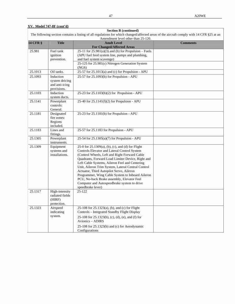
47 A20WE
XV. Model 747-8F (cont’d)
Section B (continued) The following section contains a listing of all regulations for which changed/affected areas of the aircraft comply with 14 CFR §25 at an
Amendment level other than 25-120. 14 CFR § Title Amdt Level
For Changed/Affected Areas Comments
25-11 for 25.981(a)(3) and (b) for Propulsion – Fuels (APU fuel feed system line, pumps and plumbing, and fuel system scavenge)
25.981 Fuel tank
ignition prevention.
25-125 for 25.981(c) Nitrogen Generation System (NGS)
25.1013 Oil tanks. 25-57 for 25.1013(a) and (c) for Propulsion - APU
25.1093 Induction system deicing and anti-icing provisions.
25-57 for 25.1093(b) for Propulsion - APU
25.1103 Induction system ducts.
25-23 for 25.1103(b)(2) for Propulsion - APU
25.1141 Powerplant controls: General.
25-40 for 25.1141(f)(2) for Propulsion - APU
25.1181 Designated fire zones: Regions included.
25-23 for 25.1181(b) for Propulsion - APU
25.1183 Lines and fittings.
25-57 for 25.1183 for Propulsion - APU
25.1305 Powerplant instruments.
25-54 for 25.1305(a)(7) for Propulsion - APU
25.1309 Equipment systems and installations.
25-0 for 25.1309(a), (b), (c), and (d) for Flight Controls Elevator and Lateral Control System (Control Wheels, Left and Right Forward Cable Quadrants, Forward Load Limiter Device, Right and Left Cable Systems, Aileron Feel and Centering Unit, Aileron Trim System, Lateral Central Control Actuator, Third Autopilot Servo, Aileron Programmer, Wing Cable System to Inboard Aileron PCU, No-back Brake assembly, Elevator Feel Computer and Autospeedbrake system to drive speedbrake lever)
25.1317 High-intensity radiated fields (HIRF) protection.
25-122
25.1323 Airspeed indicating system.
25-108 for 25.1323(a), (b), and (c) for Flight Controls – Integrated Standby Flight Display
25-108 for 25.1323(b), (c), (d), (e), and (f) for Avionics – ADIRS
25-108 for 25.1323(b) and (c) for Aerodynamic Configurations
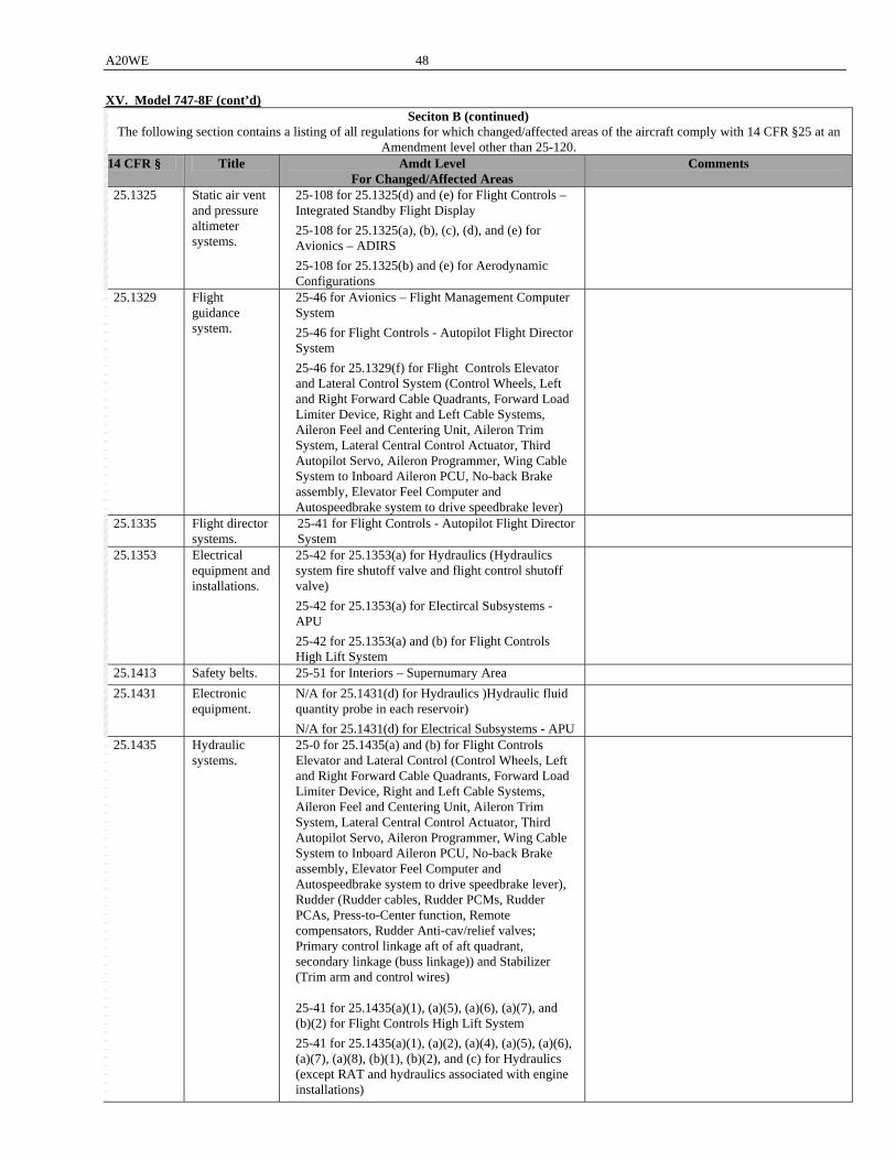
A20WE 48
XV. Model 747-8F (cont’d) Seciton B (continued)
The following section contains a listing of all regulations for which changed/affected areas of the aircraft comply with 14 CFR §25 at an Amendment level other than 25-120.
14 CFR § Title Amdt Level For Changed/Affected Areas
Comments
25.1325 Static air vent and pressure altimeter systems.
25-108 for 25.1325(d) and (e) for Flight Controls – Integrated Standby Flight Display
25-108 for 25.1325(a), (b), (c), (d), and (e) for Avionics – ADIRS
25-108 for 25.1325(b) and (e) for Aerodynamic Configurations
25.1329 Flight guidance system.
25-46 for Avionics – Flight Management Computer System
25-46 for Flight Controls - Autopilot Flight Director System
25-46 for 25.1329(f) for Flight Controls Elevator and Lateral Control System (Control Wheels, Left and Right Forward Cable Quadrants, Forward Load Limiter Device, Right and Left Cable Systems, Aileron Feel and Centering Unit, Aileron Trim System, Lateral Central Control Actuator, Third Autopilot Servo, Aileron Programmer, Wing Cable System to Inboard Aileron PCU, No-back Brake assembly, Elevator Feel Computer and Autospeedbrake system to drive speedbrake lever)
25.1335 Flight director systems.
25-41 for Flight Controls - Autopilot Flight Director System
25.1353 Electrical equipment and installations.
25-42 for 25.1353(a) for Hydraulics (Hydraulics system fire shutoff valve and flight control shutoff valve)
25-42 for 25.1353(a) for Electircal Subsystems - APU
25-42 for 25.1353(a) and (b) for Flight Controls High Lift System
25.1413 Safety belts. 25-51 for Interiors – Supernumary Area
25.1431 Electronic equipment.
N/A for 25.1431(d) for Hydraulics )Hydraulic fluid quantity probe in each reservoir)
N/A for 25.1431(d) for Electrical Subsystems - APU
25.1435 Hydraulic systems.
25-0 for 25.1435(a) and (b) for Flight Controls Elevator and Lateral Control (Control Wheels, Left and Right Forward Cable Quadrants, Forward Load Limiter Device, Right and Left Cable Systems, Aileron Feel and Centering Unit, Aileron Trim System, Lateral Central Control Actuator, Third Autopilot Servo, Aileron Programmer, Wing Cable System to Inboard Aileron PCU, No-back Brake assembly, Elevator Feel Computer and Autospeedbrake system to drive speedbrake lever), Rudder (Rudder cables, Rudder PCMs, Rudder PCAs, Press-to-Center function, Remote compensators, Rudder Anti-cav/relief valves; Primary control linkage aft of aft quadrant, secondary linkage (buss linkage)) and Stabilizer (Trim arm and control wires) 25-41 for 25.1435(a)(1), (a)(5), (a)(6), (a)(7), and (b)(2) for Flight Controls High Lift System
25-41 for 25.1435(a)(1), (a)(2), (a)(4), (a)(5), (a)(6), (a)(7), (a)(8), (b)(1), (b)(2), and (c) for Hydraulics (except RAT and hydraulics associated with engine installations)
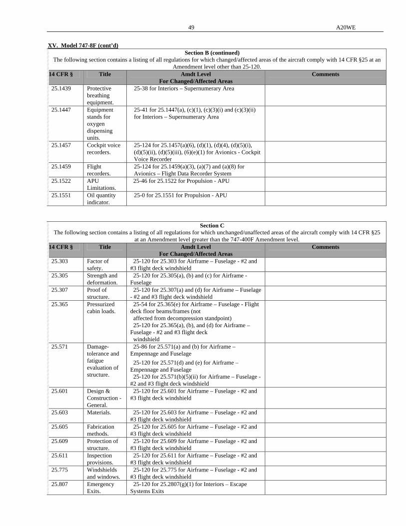
49 A20WE
XV. Model 747-8F (cont’d)
Section B (continued) The following section contains a listing of all regulations for which changed/affected areas of the aircraft comply with 14 CFR §25 at an
Amendment level other than 25-120. 14 CFR § Title Amdt Level
For Changed/Affected Areas Comments
25.1439 Protective breathing equipment.
25-38 for Interiors – Supernumerary Area
25.1447 Equipment stands for oxygen dispensing units.
25-41 for 25.1447(a), (c)(1), (c)(3)(i) and (c)(3)(ii) for Interiors – Supernumerary Area
25.1457 Cockpit voice recorders.
25-124 for 25.1457(a)(6), (d)(1), (d)(4), (d)(5)(i), (d)(5)(ii), (d)(5)(iii), (6)(e)(1) for Avionics - Cockpit Voice Recorder
25.1459 Flight recorders.
25-124 for 25.1459(a)(3), (a)(7) and (a)(8) for Avionics – Flight Data Recorder System
25.1522 APU Limitations.
25-46 for 25.1522 for Propulsion - APU
25.1551 Oil quantity indicator.
25-0 for 25.1551 for Propulsion - APU
Section C The following section contains a listing of all regulations for which unchanged/unaffected areas of the aircraft comply with 14 CFR §25
at an Amendment level greater than the 747-400F Amendment level. 14 CFR § Title Amdt Level
For Changed/Affected Areas Comments
25.303 Factor of safety.
25-120 for 25.303 for Airframe – Fuselage - #2 and #3 flight deck windshield
25.305 Strength and deformation.
25-120 for 25.305(a), (b) and (c) for Airframe - Fuselage
25.307 Proof of structure.
25-120 for 25.307(a) and (d) for Airframe – Fuselage - #2 and #3 flight deck windshield
25.365 Pressurized cabin loads.
25-54 for 25.365(e) for Airframe – Fuselage - Flight deck floor beams/frames (not affected from decompression standpoint) 25-120 for 25.365(a), (b), and (d) for Airframe – Fuselage - #2 and #3 flight deck windshield
25.571 Damage-tolerance and fatigue evaluation of structure.
25-86 for 25.571(a) and (b) for Airframe – Empennage and Fuselage
25-120 for 25.571(d) and (e) for Airframe – Empennage and Fuselage 25-120 for 25.571(b)(5)(ii) for Airframe – Fuselage - #2 and #3 flight deck windshield
25.601 Design & Construction - General.
25-120 for 25.601 for Airframe – Fuselage - #2 and #3 flight deck windshield
25.603 Materials. 25-120 for 25.603 for Airframe – Fuselage - #2 and #3 flight deck windshield
25.605 Fabrication methods.
25-120 for 25.605 for Airframe – Fuselage - #2 and #3 flight deck windshield
25.609 Protection of structure.
25-120 for 25.609 for Airframe – Fuselage - #2 and #3 flight deck windshield
25.611 Inspection provisions.
25-120 for 25.611 for Airframe – Fuselage - #2 and #3 flight deck windshield
25.775 Windshields and windows.
25-120 for 25.775 for Airframe – Fuselage - #2 and #3 flight deck windshield
25.807 Emergency Exits.
25-120 for 25.2807(g)(1) for Interiors – Escape Systems Exits
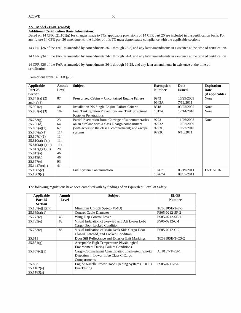
A20WE 50
XV. Model 747-8F (cont’d) Additional Certification Basis Information: Based on 14 CFR §21.101(g) for changes made to TCs applicable provisions of 14 CFR part 26 are included in the certification basis. For any future 14 CFR part 26 amendments, the holder of this TC must demonstrate compliance with the applicable sections 14 CFR §26 of the FAR as amended by Amendments 26-1 through 26-3, and any later amendments in existence at the time of certification. 14 CFR §34 of the FAR as amended by Amendments 34-1 through 34-4, and any later amendments in existence at the time of certification 14 CFR §36 of the FAR as amended by Amendments 36-1 through 36-28, and any later amendments in existence at the time of certification Exemptions from 14 CFR §25: Applicable Part 25 Section
Amndt Level
Subject Exemption Number
Date Issued
Expiration Date (if applicable)
25.841(a) (2) and (a)(3)
87 Pressurized Cabins – Uncontained Engine Failure 9943 9943A
10/29/2009 7/12/2011
None
25.901(c) 40 Installation-No Single Engine Failure Criteria 8518 03/23/2005 None 25.981(a) (3) 102 Fuel Tank Ignition Prevention-Fuel Tank Structural
Fastener Penetrations 10174 12/14/2010 None
25.783(g) 25.785(d) 25.807(a)(1) 25.807(g)(1) 25.807(i)(1) 25.810(a)(1)(i) 25.810(a)(1)(iii) 25.812(g)(1)(ii) 25.813(a) 25.813(b) 25.857(e) 25.1447(c)(1)
23 64 67 114 114 114 114 28 46 46 93 41
Partial Exemption from, Carriage of supernumeraries on an airplane with a class E cargo compartment (with access to the class E compartment) and escape systems
9793 9793A 9793B 9793C
11/26/2008 10/02/2009 10/22/2010 6/16/2011
None
25.1305(c) 25.1309(c)
Fuel System Contamination 10267 10267A
05/19/2011 08/05/2011
12/31/2016
The following regulations have been complied with by findings of an Equivalent Level of Safety:
Applicable Part 25 Section
Amndt Level
Subject ELOS Number
25.107(e)(1)(iv) Minimum Unstick Speed (VMU) TC6918SE-T-F-6 25.689(a)(1) Control Cable Diameter PS05-0212-SF-2 25.777(e) 46 Wing Flap Control Lever PS05-0212-SF-1 25.783(e) 88 Visual Indication of Forward and Aft Lower Lobe
Cargo Door Locked Condition PS05-0212-C-1
25.783(e) 88 Visual Indication of Main Deck Side Cargo Door Closed, Latched, and Locked Condition.
PS05-0212-C-2
25.811 Door Sill Reflectance and Exterior Exit Markings TC6918SE-T-CS-2 25.831(g) Acceptable High Temperature Physiological
Environment During Failure Conditions
25.857(c)(1) Cargo Compartment Classification Inadvertent Smoke Detection in Lower Lobe Class C Cargo Compartments
AT8167-T-ES-1
25.863 25.1182(a) 25.1183(a)
Engine Nacelle Power Door Opening System (PDOS) Fire Testing
PS05-0211-P-6
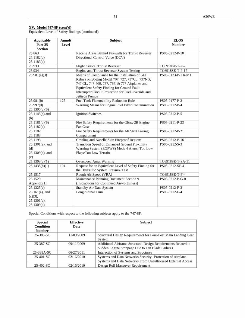
51 A20WE
XV. Model 747-8F (cont’d) Equivalent Level of Safety findings (continued):
Applicable Part 25 Section
Amndt Level
Subject ELOS Number
25.863 25.1182(a) 25.1183(a)
Nacelle Areas Behind Firewalls for Thrust Reverser Directional Control Valve (DCV)
PS05-0212-P-18
25.933 Flight Critical Thrust Reverser TC6918SE-T-P-2 25.934 Engine and Thrust Reverser System Testing TC6918SE-T-P-17 25.981(a)(3) Means of Compliance for the Installation of GFI
Relays on Boeing Model 707, 727, 737CL, 737NG, 747 CL, 747-400, 757, 767, & 777 Airplanes and Equivalent Safety Finding for Ground Fault Interrupter Circuit Protection for Fuel Override and Jettison Pumps
PS05-0123-P-1 Rev 1
25.981(b) 125 Fuel Tank Flammability Reduction Rule PS05-0177-P-2 25.997(d) 25.1305(c)(6)
Warning Means for Engine Fuel Filter Contamination PS05-0212-P-4
25.1145(a) and (b)
Ignition Switches PS05-0212-P-5
25.1181(a)(6) 25.1182(a)
Fire Safety Requirements for the GEnx-2B Engine Fan Case
PS05-0211-P-23
25.1182 25.1183
Fire Safety Requirements for the Aft Strut Fairing Compartment
PS05-0212-P-21
25.1193 Cowling and Nacelle Skin Fireproof Regions PS05-0212-P-16 25.1301(a), and (d) 25.1309(a), and (c)
Transition Speed of Enhanced Ground Proximity Warning System (EGPWS) Mode 4 Alerts; Too Low Flaps/Too Low Terrain
PS05-0212-S-3
25.1303(c)(1) Overspeed Aural Warning TC6918SE-T-SA-11 25.1435(b)(1) 104 Request for an Equivalent Level of Safety Finding for
the Hydraulic System Pressure Test PS05-0212-SF-4
25.1517 Rough Air Speed (VRA) TC6918SE-T-F-4 25.1529 Appendix H
Maintenance Planning Document Section 9 (Instructions for Continued Airworthiness)
PS05-0212-P-G-8
25.1325(e) Standby Air Data System PS05-0212-F-3 25.161(a), and (c)(3), 25.1301(a), 25.1309(a)
Longitudinal Trim PS05-0212-F-4
Special Conditions with respect to the following subjects apply to the 747-8F:
Special Condition Number
Effective Date
Subject
25-385-SC 11/09/2009 Structural Design Requirements for Four-Post Main Landing Gear System
25-387-SC 09/11/2009 Additional Airframe Structural Design Requirements Related to Sudden Engine Stoppage Due to Fan Blade Failures
25-388A-SC 06/27/2011 Interaction of Systems and Structures 25-401-SC 02/16/2010 Systems and Data Networks Security--Protection of Airplane
Systems and Data Networks From Unauthorized External Access 25-402-SC 02/16/2010 Design Roll Maneuver Requirement
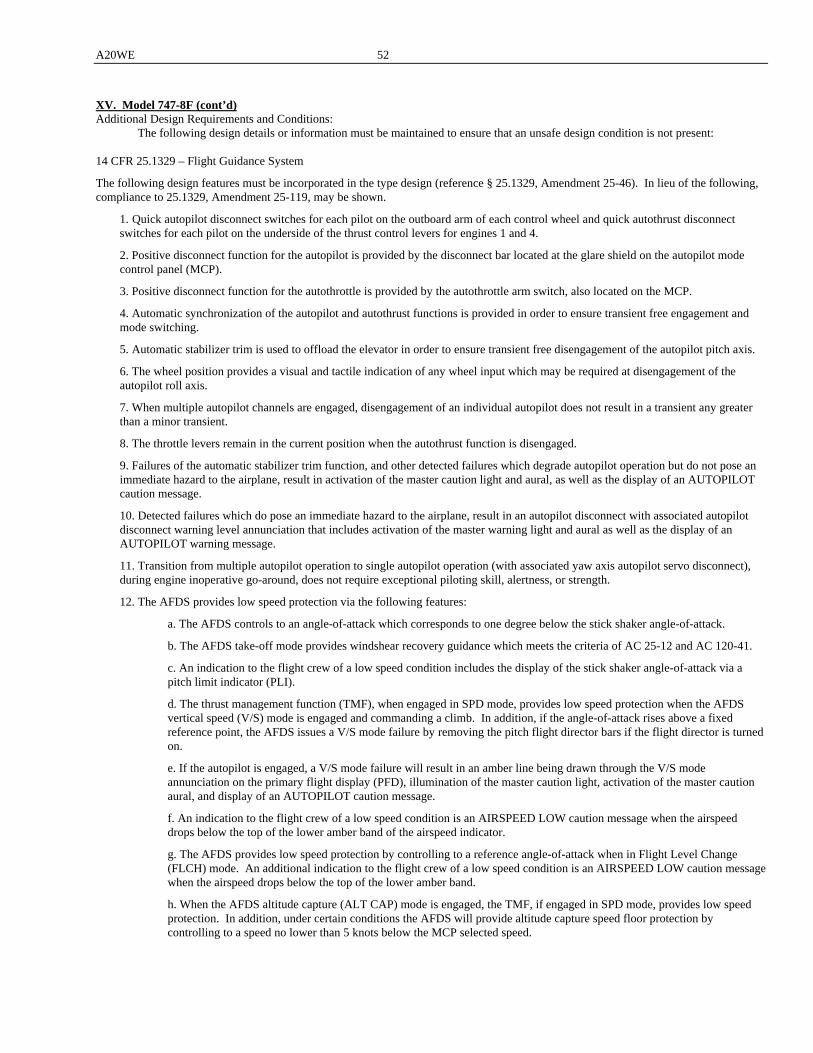
A20WE 52
XV. Model 747-8F (cont’d) Additional Design Requirements and Conditions: The following design details or information must be maintained to ensure that an unsafe design condition is not present: 14 CFR 25.1329 – Flight Guidance System
The following design features must be incorporated in the type design (reference § 25.1329, Amendment 25-46). In lieu of the following, compliance to 25.1329, Amendment 25-119, may be shown.
1. Quick autopilot disconnect switches for each pilot on the outboard arm of each control wheel and quick autothrust disconnect switches for each pilot on the underside of the thrust control levers for engines 1 and 4.
2. Positive disconnect function for the autopilot is provided by the disconnect bar located at the glare shield on the autopilot mode control panel (MCP).
3. Positive disconnect function for the autothrottle is provided by the autothrottle arm switch, also located on the MCP.
4. Automatic synchronization of the autopilot and autothrust functions is provided in order to ensure transient free engagement and mode switching.
5. Automatic stabilizer trim is used to offload the elevator in order to ensure transient free disengagement of the autopilot pitch axis.
6. The wheel position provides a visual and tactile indication of any wheel input which may be required at disengagement of the autopilot roll axis.
7. When multiple autopilot channels are engaged, disengagement of an individual autopilot does not result in a transient any greater than a minor transient.
8. The throttle levers remain in the current position when the autothrust function is disengaged.
9. Failures of the automatic stabilizer trim function, and other detected failures which degrade autopilot operation but do not pose an immediate hazard to the airplane, result in activation of the master caution light and aural, as well as the display of an AUTOPILOT caution message.
10. Detected failures which do pose an immediate hazard to the airplane, result in an autopilot disconnect with associated autopilot disconnect warning level annunciation that includes activation of the master warning light and aural as well as the display of an AUTOPILOT warning message.
11. Transition from multiple autopilot operation to single autopilot operation (with associated yaw axis autopilot servo disconnect), during engine inoperative go-around, does not require exceptional piloting skill, alertness, or strength.
12. The AFDS provides low speed protection via the following features:
a. The AFDS controls to an angle-of-attack which corresponds to one degree below the stick shaker angle-of-attack.
b. The AFDS take-off mode provides windshear recovery guidance which meets the criteria of AC 25-12 and AC 120-41.
c. An indication to the flight crew of a low speed condition includes the display of the stick shaker angle-of-attack via a pitch limit indicator (PLI).
d. The thrust management function (TMF), when engaged in SPD mode, provides low speed protection when the AFDS vertical speed (V/S) mode is engaged and commanding a climb. In addition, if the angle-of-attack rises above a fixed reference point, the AFDS issues a V/S mode failure by removing the pitch flight director bars if the flight director is turned on.
e. If the autopilot is engaged, a V/S mode failure will result in an amber line being drawn through the V/S mode annunciation on the primary flight display (PFD), illumination of the master caution light, activation of the master caution aural, and display of an AUTOPILOT caution message.
f. An indication to the flight crew of a low speed condition is an AIRSPEED LOW caution message when the airspeed drops below the top of the lower amber band of the airspeed indicator.
g. The AFDS provides low speed protection by controlling to a reference angle-of-attack when in Flight Level Change (FLCH) mode. An additional indication to the flight crew of a low speed condition is an AIRSPEED LOW caution message when the airspeed drops below the top of the lower amber band.
h. When the AFDS altitude capture (ALT CAP) mode is engaged, the TMF, if engaged in SPD mode, provides low speed protection. In addition, under certain conditions the AFDS will provide altitude capture speed floor protection by controlling to a speed no lower than 5 knots below the MCP selected speed.
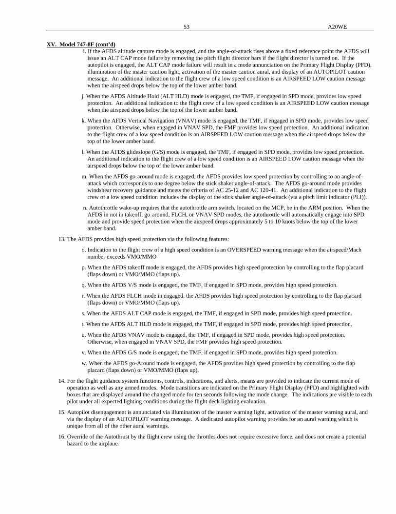
53 A20WE
XV. Model 747-8F (cont’d) i. If the AFDS altitude capture mode is engaged, and the angle-of-attack rises above a fixed reference point the AFDS will
issue an ALT CAP mode failure by removing the pitch flight director bars if the flight director is turned on. If the autopilot is engaged, the ALT CAP mode failure will result in a mode annunciation on the Primary Flight Display (PFD), illumination of the master caution light, activation of the master caution aural, and display of an AUTOPILOT caution message. An additional indication to the flight crew of a low speed condition is an AIRSPEED LOW caution message when the airspeed drops below the top of the lower amber band.
j. When the AFDS Altitude Hold (ALT HLD) mode is engaged, the TMF, if engaged in SPD mode, provides low speed protection. An additional indication to the flight crew of a low speed condition is an AIRSPEED LOW caution message when the airspeed drops below the top of the lower amber band.
k. When the AFDS Vertical Navigation (VNAV) mode is engaged, the TMF, if engaged in SPD mode, provides low speed protection. Otherwise, when engaged in VNAV SPD, the FMF provides low speed protection. An additional indication to the flight crew of a low speed condition is an AIRSPEED LOW caution message when the airspeed drops below the top of the lower amber band.
l. When the AFDS glideslope (G/S) mode is engaged, the TMF, if engaged in SPD mode, provides low speed protection. An additional indication to the flight crew of a low speed condition is an AIRSPEED LOW caution message when the airspeed drops below the top of the lower amber band.
m. When the AFDS go-around mode is engaged, the AFDS provides low speed protection by controlling to an angle-of-attack which corresponds to one degree below the stick shaker angle-of-attack. The AFDS go-around mode provides windshear recovery guidance and meets the criteria of AC 25-12 and AC 120-41. An additional indication to the flight crew of a low speed condition includes the display of the stick shaker angle-of-attack (via a pitch limit indicator (PLI)).
n. Autothrottle wake-up requires that the autothrottle arm switch, located on the MCP, be in the ARM position. When the AFDS in not in takeoff, go-around, FLCH, or VNAV SPD modes, the autothrottle will automatically engage into SPD mode and provide speed protection when the airspeed drops approximately 5 to 10 knots below the top of the lower amber band.
13. The AFDS provides high speed protection via the following features:
o. Indication to the flight crew of a high speed condition is an OVERSPEED warning message when the airspeed/Mach number exceeds VMO/MMO
p. When the AFDS takeoff mode is engaged, the AFDS provides high speed protection by controlling to the flap placard (flaps down) or VMO/MMO (flaps up).
q. When the AFDS V/S mode is engaged, the TMF, if engaged in SPD mode, provides high speed protection.
r. When the AFDS FLCH mode in engaged, the AFDS provides high speed protection by controlling to the flap placard (flaps down) or VMO/MMO (flaps up).
s. When the AFDS ALT CAP mode is engaged, the TMF, if engaged in SPD mode, provides high speed protection.
t. When the AFDS ALT HLD mode is engaged, the TMF, if engaged in SPD mode, provides high speed protection.
u. When the AFDS VNAV mode is engaged, the TMF, if engaged in SPD mode, provides high speed protection. Otherwise, when engaged in VNAV SPD, the FMF provides high speed protection.
v. When the AFDS G/S mode is engaged, the TMF, if engaged in SPD mode, provides high speed protection.
w. When the AFDS go-Around mode is engaged, the AFDS provides high speed protection by controlling to the flap placard (flaps down) or VMO/MMO (flaps up).
14. For the flight guidance system functions, controls, indications, and alerts, means are provided to indicate the current mode of operation as well as any armed modes. Mode transitions are indicated on the Primary Flight Display (PFD) and highlighted with boxes that are displayed around the changed mode for ten seconds following the mode change. The indications are visible to each pilot under all expected lighting conditions during the flight deck lighting evaluation.
15. Autopilot disengagement is annunciated via illumination of the master warning light, activation of the master warning aural, and via the display of an AUTOPILOT warning message. A dedicated autopilot warning provides for an aural warning which is unique from all of the other aural warnings.
16. Override of the Autothrust by the flight crew using the throttles does not require excessive force, and does not create a potential hazard to the airplane.
A20WE 54
XV. Model 747-8F (cont’d)
14 CFR 25.365(e)(2) – Section 41 Lower Lobe (BS 140-460) The following design features must be incorporated in the type design (reference § 25.365, Amendment 25-54). In lieu of incorporating the following design features, compliance to § 25.365, Amendment 25-120, may be shown.
Section 41 Lower Lobe (BS 140-460): When evaluating this compartment for compliance to § 25.365, the compartment must be analyzed using the following two conditions: (1) A 3.7 square foot opening (forward EE Bay access door) with the BS 464 cargo liner intact (3.7 sf), and (2) A 20.0 square foot opening with the BS 464 cargo liner blown down. This essentially combines the Section 41 Lower Lobe and
the forward cargo compartment into one compartment in the analysis. 14 CFR 25.561(c)(1)(ii) – Auxiliary Power Unit Fuel Line in Section 46 The following design features must be incorporated in the type design. In lieu of incorporating the following design features, compliance to § 25.561(c)(1)(ii), Amendment 25-120, may be shown.
(1) The Section 46 floor beams must be designed to protect the auxiliary power unit (APU) fuel lines from an emergency landing load
event of a minimum of 5.2 g's down and 1.5 g’s up. (2) The APU fuel line must be routed through the main deck floor beams just outboard of BL 0 to minimize potential for all types of
penetration (including rotor burst, wheels up landing impact, etc). (3) Occupants must be located no less than 72 feet forward of the forward-most potential penetration location in the APU fuel hose. Damage Tolerance and Fatigue Evaluation of Structure 14 CFR 25.571(a) and (b) – Wing, Empennage, Fuselage, Floors and Doors The following design features must be incorporated in the type design (reference § 25.571(a) and (b), Amendment 25-86). In lieu of incorporating the following design features, compliance to § 25.571(a) and (b), Amendment 25-120, may be shown.
(1) For the 747-8F structure, an evaluation of the existing damage tolerance analysis (DTA) inspection program identified in the Supplemental Structural Inspection Document (SSID) must be performed for any required changes due to loads, geometry changes, material changes, etc. The resulting inspection requirements for the 747-8F must be included in Section 9 (Airworthiness Limitations) of the Boeing Maintenance Planning Document (MPD) D621U400 in accordance with § 25.571(a)(3) at Amendment 25-120.
(2) The above evaluation must include loading magnitudes and loading spectra which are developed in accordance with § 25.571 at Amendment 25-120. This includes usage of the 1.15 factor for pressure acting alone in accordance with § 25.571(b)(5) at Amendment 25-120.
(3) Maintenance instructions must be based on in-service data and fatigue testing to ensure freedom from widespread fatigue damage.
14 CFR 25.809(a) – Outside Viewing means for Flight Deck Overhead Exit
The following design features must be incorporated in the type design (reference § 25.809(a), Amendment 25-47). In lieu of incorporating the following design features, compliance to § 25.809(a), Amendment 25-120, may be shown.
(1) Large windows installed adjacent to the overhead flight deck exit door that provide a means for outside viewing to determine if there is a hazard (such as a fire) that would pose an immediate threat to the occupants of the airplane if the emergency exit were to be opened.
(2) 8 inertia reels (with harnesses) installed for egress out flight deck overhead exit door.
55 A20WE
XV. Model 747-8F (cont’d) The following design details must be maintained to ensure that an unsafe design feature is not present: Following fire/smoke detection, the crew will follow the AFM procedure to depressurize the cabin and ascend or descend the airplane
to an altitude of 25,000 feet until final descent to a suitable airport is possible. Class E cargo compartment liners will be tested to meet requirements of 14 CFR part 25, appendix F part III (Amdt. 25.83). Except at
the following locations: 1. The linings above the cargo compartment ceiling in the stairwell to the upper deck; 2. Equipment/features mounted in the sidewall liners (and any sidewall liner joints to the equipment) such as the nose door
control panel; 3. Liner joints at door edge frames (door 1, side cargo door, nose door); 4. Soft liner and joints above side cargo door where the hinges penetrate; 5. The aluminum and fiberglass dado panels (and associated joints) installed along the cargo compartment sidewalls from the
cargo floor to approximately 10” to 15” above the floor. Air grills in the ceiling panels between station 520 and 620 that are painted with intumescent paint which expand and close off the
grill when exposed to a fire. Protection of wires required for continued safe flight and landing inside the Class E compartment will be accomplished by any one,
or combination of the following: 1. Routing behind fire resistant liners; 2. Routing of redundant wires on opposite sides of the main deck floor and/or opposite sides of the crown area, and/or with a
minimum separation of 6’; 3. Placement of air dams or fire stops behind cargo liners as required to prevent propagation of fire behind the liner; 4. Use of fire resistant wire or insulation where required to protect wire in locations subject to potential high temperatures on the
backside of cargo liners and above ceiling panels (below the flight deck for example); and 5. Placement of special fire resistant covers behind air return grilles/decompression vents as required. At least one critical oxygen line, which provides oxygen to the flight deck, will also be protected by fire resistant sidewall liner
material and a protective fiberglass cover on the associated air return grille/decompression vent. Additional information is listed in Section 9 of Boeing Maintenance Planning Data Document D011U721-02 or the applicable engine
Type Certificate Data Sheet. The more restrictive requirement from these two documents shall be in force. Production Basis: Production Certificate No. 700 has been issued to The Boeing Company. Equipment: The basic required equipment as prescribed in the applicable airworthiness regulations (see Certification Basis) must be
installed in the aircraft for certification. XVI. Model 747-8 (Approved December 14, 2011) Transport Category The 747-8 series is based on the model 747-400 series aircraft with design changes to the empennage, fuselage, landing gear, wings, engines, fuel systems, and other aircraft systems as defined in the certification basis within this section. The certification basis for areas unaffected by this change from the 747-400 series aircraft will remain certified at the 14 CFR Part 25 Amendment level of their original certification date. Engines: 4 General Electric Turbofan Engines Model: GEnx-2B67B (Engine Type Certificate No. E00078NE) Fuel: General Electric Turbofan Engines Fuels conforming to: ASTM D-1655 grades Jet-A and Jet A-1 MIL-T-5624 grade JP-5 MIL-T-83133 grade JP-8 are acceptable Fuels produced to other specifications and having properties meeting the requirements of the above specifications are acceptable.
The fuel and any fuel additives must conform to the relevant Engine Operating Instructions. Engine Limits: General Electric Turbofan Engines See the appropriate FAA approved Airplane Flight Manual for engine ratings. Airspeed Limits: VMO/MMO = 365/0.9 (KCAS) See the appropriate FAA Approved Airplane Flight Manual for other
airspeed limits C.G. Range: See the appropriate FAA Approved Airplane Flight Manual
A20WE 56
Empty Weight C.G.: See the appropriate FAA Approved Airplane Flight Manual Datum: See the appropriate Weight and Balance Control Manual Leveling Means: See the appropriate FAA Approved Airplane Flight Manual Maximum Weights: See the appropriate FAA approved Airplane Flight Manual Minimum Crew: For all flights, 2 persons (pilot, copilot). Maximum Number of : 0 Seats Maximum Compartment: See the appropriate Weight and Balance Control Manual Weights Fuel Capacity: See the appropriate Weight and Balance Control Manual Oil Capacity: See the appropriate Weight and Balance Control Manual Maximum Operating: 43,100 Altitude Control Surface: To insure proper operation of the airplane, the movement of the various control surfaces must be carefully Movements controlled by proper rigging of the flight control systems. The airplane must, therefore, be rigged according
to the following FAA-approved data: Boeing Drawing Numbers: 251U1001 Rigging Instructions Lateral Controls 251U1003 Rigging Instructions Speed Brakes 251U2001 Rigging Instructions Elevator Controls 251U3002 Rigging Instructions Rudder Controls 251U4001 Rigging Instructions Stablizer Trim Controls 114U0001 Rigging Instructions Leading Edge Slats Controls 253U5001 Rigging Instructions Control Stand 256U5001 Rigging Instructions Trailing Edge Flap Controls Model Eligible Serial Numbers 747-8KB 37544 Certification Basis: The 747-8 series is based on the model 747-400 series aircraft with design changes to the empennage, fuselage, landing gear, wings, engines, fuel systems, and other aircraft systems as defined in the certification basis within this section. The certification basis for areas unaffected by this change from the 747-400 series aircraft will remain certified at the 14 CFR Part 25 Amendment level of their original certification date. The certification basis for areas changed or affected by the 747-8 minor model is 14 CFR part 25, as amended by Amendment 25-1 through Amendment 25-120 with exceptions permitted by 14 CFR 21.101. Section A documents the changed/affected areas of the aircraft. Section B documents all regulations for which there are exceptions from Amendment 25-120 for the changed/affected areas. Section C documents unchanged/unaffected areas for which compliance has been shown at an Amendment level higher than the 747-400 Amendment level. A. The following section contains a listing of all areas that are changed/affected as part of the 747-8 minor model.
Airplane Area Changed/Affected Areas
Static Loads; Dynamic Flight Loads; Dynamic Ground Loads; Flutter
Flotation and ditching
Weight and balance
Airplane Level
Aerodynamic Stability & Control; Aerodynamic Performace; Aerodynamic Configurations
57 A20WE
XVI. Model 747-8 (cont’d)
Airplane Area Changed/Affected Areas Airframe - Empennage
All empennage (including the outboard elevator balance weight towers) except: Inboard elevator, remainder of outboard elevator.
Airframe - Fuselage
All fuselage (includes all fuselage, floors, doors, and window structure) except: BS 140 pressure bulkhead; frames, S-0 to S-13, BS 160 to BS 320; flight deck surround skins/stringers from S-0 to S-13, BS 220-300; flight deck floor beams from BS 220-300; structural supports and sills for flight deck windshields; crown skin from S-0 to S-6 from BS 280 to 520; upper deck side of body shear trusses; 9G intercostals for upper deck galleys, upper deck floor decompression trusses, side of body shear panels; BS 2360 aft pressure dome and APU tail cone; Nose radome and nose landing gear doors; Upper deck emergency exit doors , flight deck overhead emergency exit door, and forward and center
electrical equipment access doors Pitot static line plumbing
Integrated Display System (IDS)
Modularized Avionics and Warning Electronics Assembly (MAWEA)
Flight Management Computer (FMC)
Communication Management Unit (CMU)
Enhanced Ground Proximity Warning System (EGPWS)
Central Maintenance Computer System (CMCS)
Airplane Condition and Monitoring System (Data Management Unit (DMU) and Quick Access Recorder (QAR))
Low Range Radio Altimeter (LRRA)
Multi-Mode Receiver (MMR)
Distance Measuring Equipment (DME)
Automatic Direction Finder (ADF)
VHF Omnidirectional Range/Marker Beacon (VOR/MB)
Air Data Inertial Reference System (ADIRS) software
SATCOM
Cockpit Voice Recorder (CVR)
Flight Deck (FD) Printer
Flight Data Recorder Systems (FDRS)
Onboard Network System (ONS)
Terminal Wireless LAN Unit (TWLU)
Automatic Fixed Emergency Locator Transmitter (ELT)
HF/VHF Radio Communication Panel
Traffic Alert and Collision Avoidance System (TCAS) and Air Traffic Control (ATC) Systems
Avionics
Flight Deck Audio System (Audio Management Unit (AMU) and Audio Control Panels (ACP)) Provisions including structural and electrical for Cargo Handling System for Lower Lobe Compartments Cargo
Cargo Furnishings, Linings and Placards
Duct Leak Detection System (DLDS)
Integrated Wingtip Light Assembly (IWLA)
Integrated Drive Generator (IDG)
Main and APU battery
Cabin Services System (CSS)
Weight and Balance Computer of the On-Board Weight and Balance System Electrical Power Generation System
Electrical Sub-systems
Service and maintenance lights in the wheel wells, AC pack bay, Tailcone/APU compartment and forward EE bay
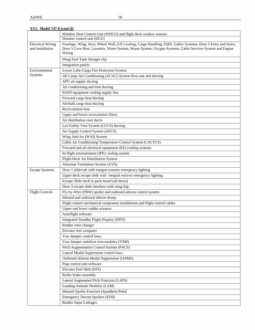
A20WE 58
XVI. Model 747-8 (cont’d) Window Heat Control Unit (WHCU) and flight deck window sensors
Dimmer control unit (DCU)
Fuselage, Wing, Strut, Wheel Well, E/E Cooling, Cargo Handling, FQIS, Galley Systems, Door 2 Entry and Stairs, Door 5 Crew Rest, Lavatory, Water System, Waste System, Oxygen Systems, Cabin Services System and Engine Wiring
Wing Fuel Tank Stringer clip
Electrical Wiring and Installation
Integration panels
Lower Lobe Cargo Fire Protection System
Aft Cargo Air Conditioning (ACAC) System flow rate and ducting
APU air supply ducting
Air conditioning and trim ducting.
E6/E9 equipment cooling supply line
Forward cargo heat ducting
Aft/bulk cargo heat ducting
Recirculation fans
Upper and lower recirculation filters
Air distribution riser ducts.
Lav/Galley Vent System (LGVS) ducting
Air Supply Control System (ASCS)
Wing Anti-Ice (WAI) System
Cabin Air Conditioning Temperature Control System (CACTCS)
Forward and aft electrical equipment (EE) cooling systems
In-flight entertainment (IFE) cooling system
Flight Deck Air Distribution System
Environmental Systems
Alternate Ventilation System (AVS)
Door 1 slide/raft with integral exterior emergency lighting
Upper deck escape slide with integral exterior emergency lighting
Escape Slide latch to pack board (all doors)
Escape Systems
Door 3 escape slide interface with wing flap
Fly-by-Wire (FBW) spoiler and outboard aileron control system.
Inboard and outboard aileron droop.
Flight control mechanical component installations and flight control cables
Upper and lower rudder actuator
Autoflight software
Integrated Standby Flight Display (ISFD)
Rudder ratio changer
Elevator feel computer
Yaw damper control laws.
Yaw damper stabilizer trim modules (YSM)
Pitch Augmentation Control System (PACS)
Lateral Modal Suppression control laws.
Outboard Aileron Modal Suppression (OAMS)
Flap control unit software
Elevator Feel Shift (EFS)
Roller brake assembly
Lateral Augmented Pitch Function (LAPS)
Landing Attitude Modifier (LAM)
Inboard Spoiler Function (Spudders) Pedal
Emergency Decent Spoilers (EDS)
Flight Controls
Rudder Input Linkages
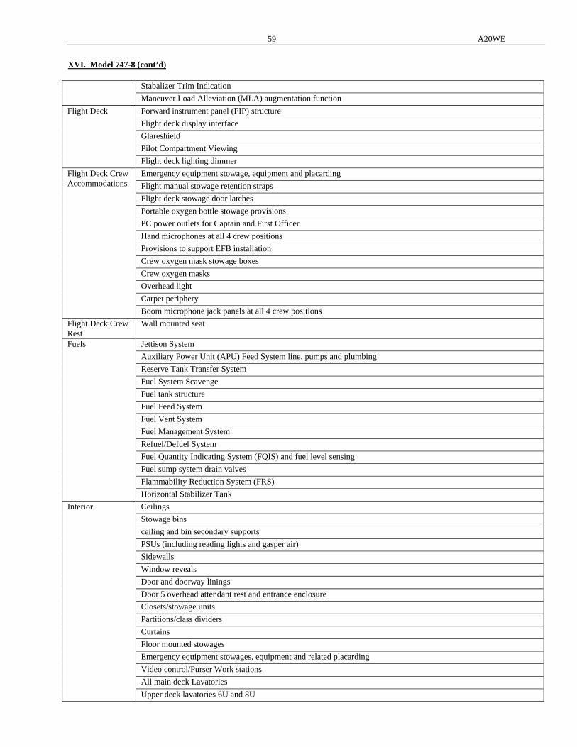
59 A20WE
XVI. Model 747-8 (cont’d)
Stabalizer Trim Indication
Maneuver Load Alleviation (MLA) augmentation function
Forward instrument panel (FIP) structure
Flight deck display interface
Glareshield
Pilot Compartment Viewing
Flight Deck
Flight deck lighting dimmer
Emergency equipment stowage, equipment and placarding
Flight manual stowage retention straps
Flight deck stowage door latches
Portable oxygen bottle stowage provisions
PC power outlets for Captain and First Officer
Hand microphones at all 4 crew positions
Provisions to support EFB installation
Crew oxygen mask stowage boxes
Crew oxygen masks
Overhead light
Carpet periphery
Flight Deck Crew Accommodations
Boom microphone jack panels at all 4 crew positions
Flight Deck Crew Rest
Wall mounted seat
Jettison System
Auxiliary Power Unit (APU) Feed System line, pumps and plumbing
Reserve Tank Transfer System
Fuel System Scavenge
Fuel tank structure
Fuel Feed System
Fuel Vent System
Fuel Management System
Refuel/Defuel System
Fuel Quantity Indicating System (FQIS) and fuel level sensing
Fuel sump system drain valves
Flammability Reduction System (FRS)
Fuels
Horizontal Stabilizer Tank
Ceilings
Stowage bins
ceiling and bin secondary supports
PSUs (including reading lights and gasper air)
Sidewalls
Window reveals
Door and doorway linings
Door 5 overhead attendant rest and entrance enclosure
Closets/stowage units
Partitions/class dividers
Curtains
Floor mounted stowages
Emergency equipment stowages, equipment and related placarding
Video control/Purser Work stations
All main deck Lavatories
Interior
Upper deck lavatories 6U and 8U
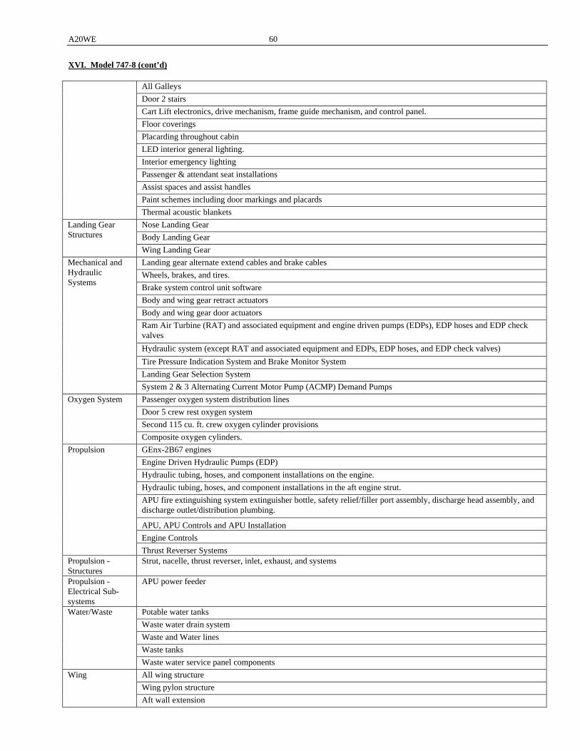
A20WE 60
XVI. Model 747-8 (cont’d)
All Galleys
Door 2 stairs
Cart Lift electronics, drive mechanism, frame guide mechanism, and control panel.
Floor coverings
Placarding throughout cabin
LED interior general lighting.
Interior emergency lighting
Passenger & attendant seat installations
Assist spaces and assist handles
Paint schemes including door markings and placards
Thermal acoustic blankets
Nose Landing Gear
Body Landing Gear
Landing Gear Structures
Wing Landing Gear
Landing gear alternate extend cables and brake cables
Wheels, brakes, and tires.
Brake system control unit software
Body and wing gear retract actuators
Body and wing gear door actuators
Ram Air Turbine (RAT) and associated equipment and engine driven pumps (EDPs), EDP hoses and EDP check valves
Hydraulic system (except RAT and associated equipment and EDPs, EDP hoses, and EDP check valves)
Tire Pressure Indication System and Brake Monitor System
Landing Gear Selection System
Mechanical and Hydraulic Systems
System 2 & 3 Alternating Current Motor Pump (ACMP) Demand Pumps
Passenger oxygen system distribution lines
Door 5 crew rest oxygen system
Second 115 cu. ft. crew oxygen cylinder provisions
Oxygen System
Composite oxygen cylinders.
GEnx-2B67 engines
Engine Driven Hydraulic Pumps (EDP)
Hydraulic tubing, hoses, and component installations on the engine.
Hydraulic tubing, hoses, and component installations in the aft engine strut.
APU fire extinguishing system extinguisher bottle, safety relief/filler port assembly, discharge head assembly, and discharge outlet/distribution plumbing.
APU, APU Controls and APU Installation
Engine Controls
Propulsion
Thrust Reverser Systems Propulsion - Structures
Strut, nacelle, thrust reverser, inlet, exhaust, and systems
Propulsion - Electrical Sub-systems
APU power feeder
Potable water tanks
Waste water drain system
Waste and Water lines
Waste tanks
Water/Waste
Waste water service panel components
All wing structure
Wing pylon structure
Wing
Aft wall extension
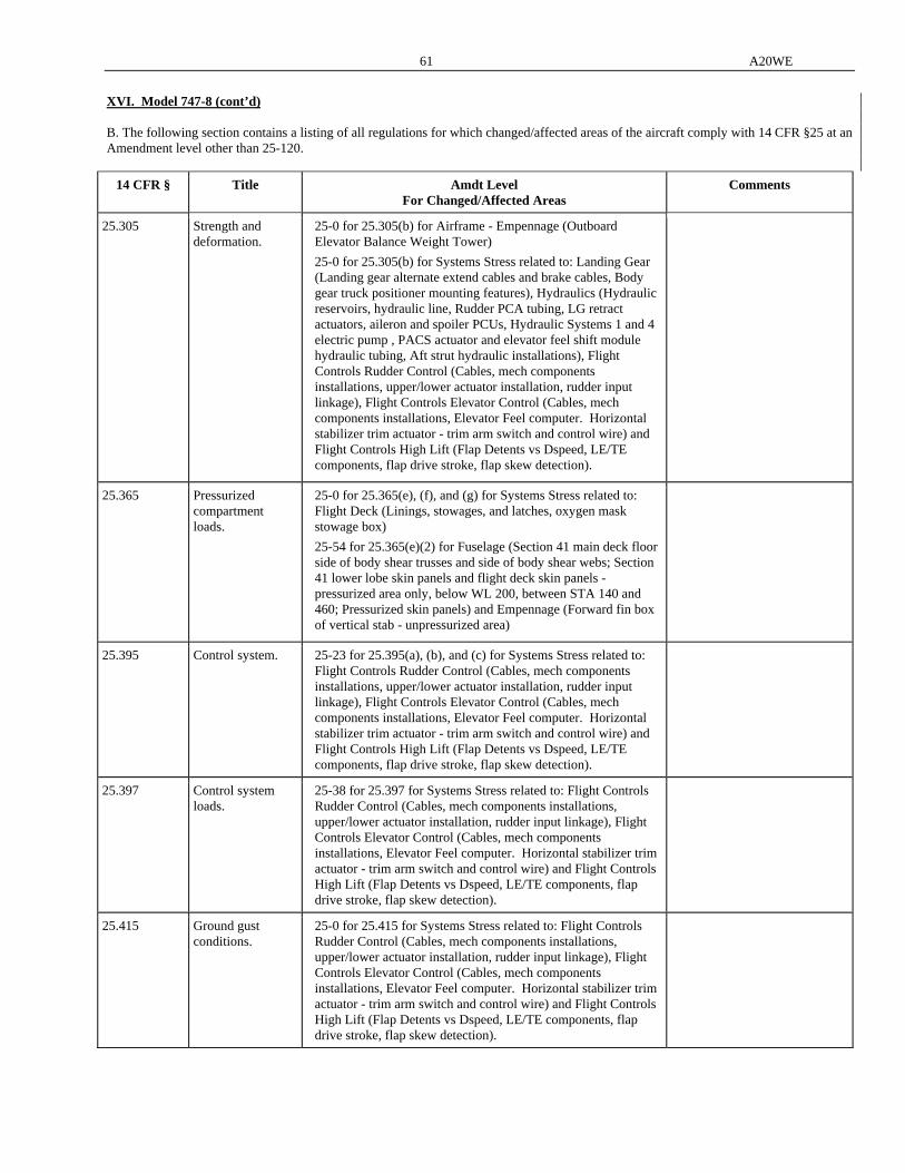
61 A20WE
XVI. Model 747-8 (cont’d) B. The following section contains a listing of all regulations for which changed/affected areas of the aircraft comply with 14 CFR §25 at an Amendment level other than 25-120.
14 CFR § Title Amdt Level For Changed/Affected Areas
Comments
25.305 Strength and deformation.
25-0 for 25.305(b) for Airframe - Empennage (Outboard Elevator Balance Weight Tower)
25-0 for 25.305(b) for Systems Stress related to: Landing Gear (Landing gear alternate extend cables and brake cables, Body gear truck positioner mounting features), Hydraulics (Hydraulic reservoirs, hydraulic line, Rudder PCA tubing, LG retract actuators, aileron and spoiler PCUs, Hydraulic Systems 1 and 4 electric pump , PACS actuator and elevator feel shift module hydraulic tubing, Aft strut hydraulic installations), Flight Controls Rudder Control (Cables, mech components installations, upper/lower actuator installation, rudder input linkage), Flight Controls Elevator Control (Cables, mech components installations, Elevator Feel computer. Horizontal stabilizer trim actuator - trim arm switch and control wire) and Flight Controls High Lift (Flap Detents vs Dspeed, LE/TE components, flap drive stroke, flap skew detection).
25.365 Pressurized compartment loads.
25-0 for 25.365(e), (f), and (g) for Systems Stress related to: Flight Deck (Linings, stowages, and latches, oxygen mask stowage box)
25-54 for 25.365(e)(2) for Fuselage (Section 41 main deck floor side of body shear trusses and side of body shear webs; Section 41 lower lobe skin panels and flight deck skin panels - pressurized area only, below WL 200, between STA 140 and 460; Pressurized skin panels) and Empennage (Forward fin box of vertical stab - unpressurized area)
25.395 Control system. 25-23 for 25.395(a), (b), and (c) for Systems Stress related to: Flight Controls Rudder Control (Cables, mech components installations, upper/lower actuator installation, rudder input linkage), Flight Controls Elevator Control (Cables, mech components installations, Elevator Feel computer. Horizontal stabilizer trim actuator - trim arm switch and control wire) and Flight Controls High Lift (Flap Detents vs Dspeed, LE/TE components, flap drive stroke, flap skew detection).
25.397 Control system loads.
25-38 for 25.397 for Systems Stress related to: Flight Controls Rudder Control (Cables, mech components installations, upper/lower actuator installation, rudder input linkage), Flight Controls Elevator Control (Cables, mech components installations, Elevator Feel computer. Horizontal stabilizer trim actuator - trim arm switch and control wire) and Flight Controls High Lift (Flap Detents vs Dspeed, LE/TE components, flap drive stroke, flap skew detection).
25.415 Ground gust conditions.
25-0 for 25.415 for Systems Stress related to: Flight Controls Rudder Control (Cables, mech components installations, upper/lower actuator installation, rudder input linkage), Flight Controls Elevator Control (Cables, mech components installations, Elevator Feel computer. Horizontal stabilizer trim actuator - trim arm switch and control wire) and Flight Controls High Lift (Flap Detents vs Dspeed, LE/TE components, flap drive stroke, flap skew detection).
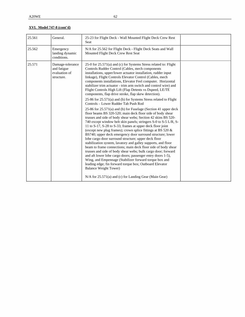
A20WE 62
XVI. Model 747-8 (cont’d)
25.561 General. 25-23 for Flight Deck - Wall Mounted Flight Deck Crew Rest Seat
25.562 Emergency landing dynamic conditions.
N/A for 25.562 for Flight Deck - Flight Deck Seats and Wall Mounted Flight Deck Crew Rest Seat
25.571 Damage-tolerance and fatigue evaluation of structure.
25-0 for 25.571(a) and (c) for Systems Stress related to: Flight Controls Rudder Control (Cables, mech components installations, upper/lower actuator installation, rudder input linkage), Flight Controls Elevator Control (Cables, mech components installations, Elevator Feel computer. Horizontal stabilizer trim actuator - trim arm switch and control wire) and Flight Controls High Lift (Flap Detents vs Dspeed, LE/TE components, flap drive stroke, flap skew detection).
25-86 for 25.571(a) and (b) for Systems Stress related to Flight Controls – Lower Rudder Tab Push Rod
25-86 for 25.571(a) and (b) for Fuselage (Section 41 upper deck floor beams BS 320-520; main deck floor side of body shear trusses and side of body shear webs; Section 42 skins BS 520-740 except window belt skin panels; stringers S-0 to S-5 L/R, S-11 to S-17, S-28 to S-33; frames at upper deck floor joint (except new plug frames); crown splice fittings at BS 520 & BS740; upper deck emergency door surround structure; lower lobe cargo door surround structure; upper deck floor stabilization system, lavatory and galley supports, and floor beam to frame connections; main deck floor side of body shear trusses and side of body shear webs; bulk cargo door; forward and aft lower lobe cargo doors; passenger entry doors 1-5), Wing, and Empennage (Stabilizer forward torque box and leading edge; fin forward torque box; Outboard Elevator Balance Weight Tower) N/A for 25.571(a) and (c) for Landing Gear (Main Gear)
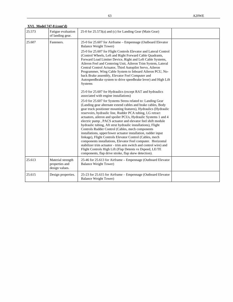
63 A20WE
XVI. Model 747-8 (cont’d)
25.573 Fatigue evaluation of landing gear.
25-0 for 25.573(a) and (c) for Landing Gear (Main Gear)
25.607 Fasteners. 25-0 for 25.607 for Airframe – Empennage (Outboard Elevator Balance Weight Tower)
25-0 for 25.607 for Flight Controls Elevator and Lateral Control (Control Wheels, Left and Right Forward Cable Quadrants, Forward Load Limiter Device, Right and Left Cable Systems, Aileron Feel and Centering Unit, Aileron Trim System, Lateral Central Control Actuator, Third Autopilot Servo, Aileron Programmer, Wing Cable System to Inboard Aileron PCU, No-back Brake assembly, Elevator Feel Computer and Autospeedbrake system to drive speedbrake lever) and High Lift Systems 25-0 for 25.607 for Hydraulics (except RAT and hydraulics associated with engine installations)
25-0 for 25.607 for Systems Stress related to: Landing Gear (Landing gear alternate extend cables and brake cables, Body gear truck positioner mounting features), Hydraulics (Hydraulic reservoirs, hydraulic line, Rudder PCA tubing, LG retract actuators, aileron and spoiler PCUs, Hydraulic Systems 1 and 4 electric pump , PACS actuator and elevator feel shift module hydraulic tubing, Aft strut hydraulic installations), Flight Controls Rudder Control (Cables, mech components installations, upper/lower actuator installation, rudder input linkage), Flight Controls Elevator Control (Cables, mech components installations, Elevator Feel computer. Horizontal stabilizer trim actuator - trim arm switch and control wire) and Flight Controls High Lift (Flap Detents vs Dspeed, LE/TE components, flap drive stroke, flap skew detection).
25.613 Material strength properties and design values.
25-46 for 25.613 for Airframe – Empennage (Outboard Elevator Balance Weight Tower)
25.615 Design properties. 25-23 for 25.615 for Airframe – Empennage (Outboard Elevator Balance Weight Tower)
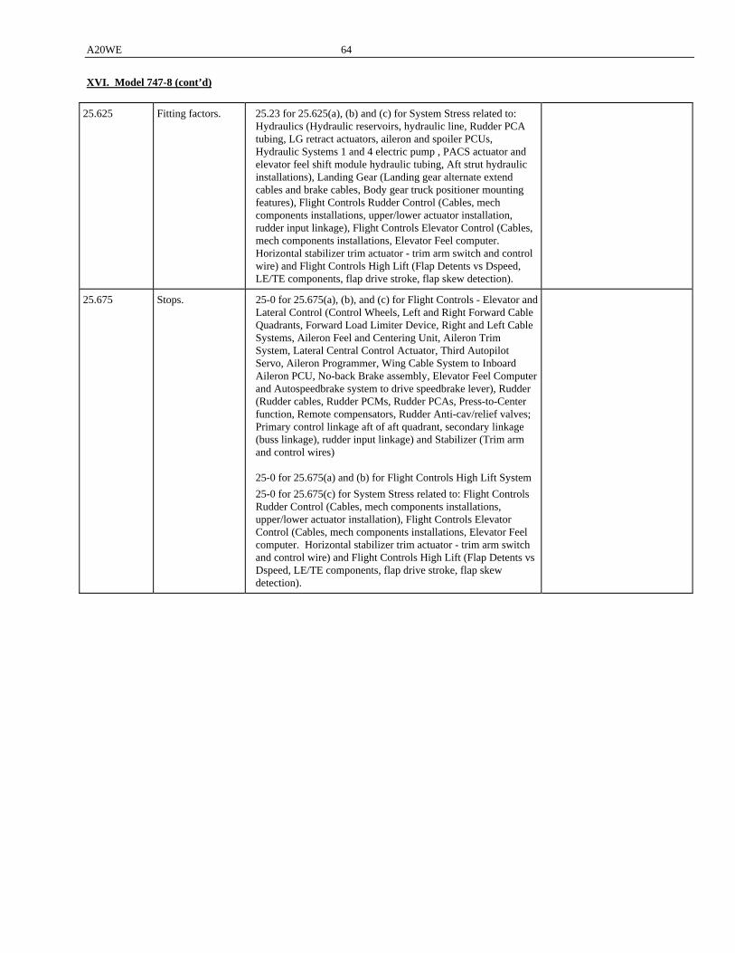
A20WE 64
XVI. Model 747-8 (cont’d)
25.625 Fitting factors. 25.23 for 25.625(a), (b) and (c) for System Stress related to: Hydraulics (Hydraulic reservoirs, hydraulic line, Rudder PCA tubing, LG retract actuators, aileron and spoiler PCUs, Hydraulic Systems 1 and 4 electric pump , PACS actuator and elevator feel shift module hydraulic tubing, Aft strut hydraulic installations), Landing Gear (Landing gear alternate extend cables and brake cables, Body gear truck positioner mounting features), Flight Controls Rudder Control (Cables, mech components installations, upper/lower actuator installation, rudder input linkage), Flight Controls Elevator Control (Cables, mech components installations, Elevator Feel computer. Horizontal stabilizer trim actuator - trim arm switch and control wire) and Flight Controls High Lift (Flap Detents vs Dspeed, LE/TE components, flap drive stroke, flap skew detection).
25.675 Stops. 25-0 for 25.675(a), (b), and (c) for Flight Controls - Elevator and Lateral Control (Control Wheels, Left and Right Forward Cable Quadrants, Forward Load Limiter Device, Right and Left Cable Systems, Aileron Feel and Centering Unit, Aileron Trim System, Lateral Central Control Actuator, Third Autopilot Servo, Aileron Programmer, Wing Cable System to Inboard Aileron PCU, No-back Brake assembly, Elevator Feel Computer and Autospeedbrake system to drive speedbrake lever), Rudder (Rudder cables, Rudder PCMs, Rudder PCAs, Press-to-Center function, Remote compensators, Rudder Anti-cav/relief valves; Primary control linkage aft of aft quadrant, secondary linkage (buss linkage), rudder input linkage) and Stabilizer (Trim arm and control wires) 25-0 for 25.675(a) and (b) for Flight Controls High Lift System
25-0 for 25.675(c) for System Stress related to: Flight Controls Rudder Control (Cables, mech components installations, upper/lower actuator installation), Flight Controls Elevator Control (Cables, mech components installations, Elevator Feel computer. Horizontal stabilizer trim actuator - trim arm switch and control wire) and Flight Controls High Lift (Flap Detents vs Dspeed, LE/TE components, flap drive stroke, flap skew detection).
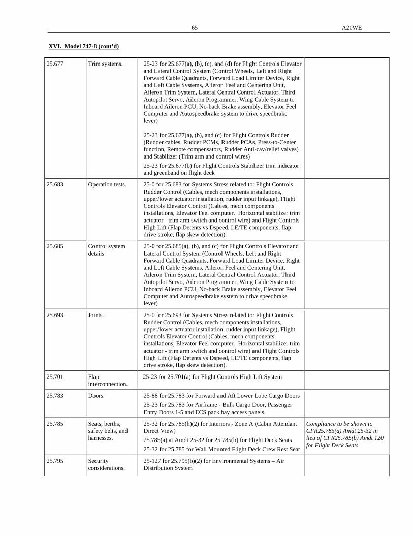
65 A20WE
XVI. Model 747-8 (cont’d)
25.677 Trim systems. 25-23 for 25.677(a), (b), (c), and (d) for Flight Controls Elevator and Lateral Control System (Control Wheels, Left and Right Forward Cable Quadrants, Forward Load Limiter Device, Right and Left Cable Systems, Aileron Feel and Centering Unit, Aileron Trim System, Lateral Central Control Actuator, Third Autopilot Servo, Aileron Programmer, Wing Cable System to Inboard Aileron PCU, No-back Brake assembly, Elevator Feel Computer and Autospeedbrake system to drive speedbrake lever) 25-23 for 25.677(a), (b), and (c) for Flight Controls Rudder (Rudder cables, Rudder PCMs, Rudder PCAs, Press-to-Center function, Remote compensators, Rudder Anti-cav/relief valves) and Stabilizer (Trim arm and control wires)
25-23 for 25.677(b) for Flight Controls Stabilizer trim indicator and greenband on flight deck
25.683 Operation tests. 25-0 for 25.683 for Systems Stress related to: Flight Controls Rudder Control (Cables, mech components installations, upper/lower actuator installation, rudder input linkage), Flight Controls Elevator Control (Cables, mech components installations, Elevator Feel computer. Horizontal stabilizer trim actuator - trim arm switch and control wire) and Flight Controls High Lift (Flap Detents vs Dspeed, LE/TE components, flap drive stroke, flap skew detection).
25.685 Control system details.
25-0 for 25.685(a), (b), and (c) for Flight Controls Elevator and Lateral Control System (Control Wheels, Left and Right Forward Cable Quadrants, Forward Load Limiter Device, Right and Left Cable Systems, Aileron Feel and Centering Unit, Aileron Trim System, Lateral Central Control Actuator, Third Autopilot Servo, Aileron Programmer, Wing Cable System to Inboard Aileron PCU, No-back Brake assembly, Elevator Feel Computer and Autospeedbrake system to drive speedbrake lever)
25.693 Joints. 25-0 for 25.693 for Systems Stress related to: Flight Controls Rudder Control (Cables, mech components installations, upper/lower actuator installation, rudder input linkage), Flight Controls Elevator Control (Cables, mech components installations, Elevator Feel computer. Horizontal stabilizer trim actuator - trim arm switch and control wire) and Flight Controls High Lift (Flap Detents vs Dspeed, LE/TE components, flap drive stroke, flap skew detection).
25.701 Flap interconnection.
25-23 for 25.701(a) for Flight Controls High Lift System
25.783 Doors. 25-88 for 25.783 for Forward and Aft Lower Lobe Cargo Doors
25-23 for 25.783 for Airframe - Bulk Cargo Door, Passenger Entry Doors 1-5 and ECS pack bay access panels.
25.785 Seats, berths, safety belts, and harnesses.
25-32 for 25.785(h)(2) for Interiors - Zone A (Cabin Attendant Direct View)
25.785(a) at Amdt 25-32 for 25.785(b) for Flight Deck Seats
25-32 for 25.785 for Wall Mounted Flight Deck Crew Rest Seat
Compliance to be shown to CFR25.785(a) Amdt 25-32 in lieu of CFR25.785(b) Amdt 120 for Flight Deck Seats.
25.795 Security considerations.
25-127 for 25.795(b)(2) for Environmental Systems – Air Distribution System
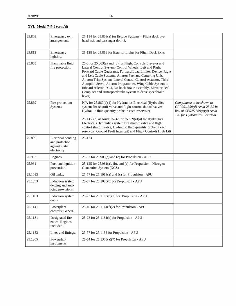
A20WE 66
XVI. Model 747-8 (cont’d)
25.809 Emergency exit arrangement.
25-114 for 25.809(a) for Escape Systems – Flight deck over head exit and passenger door 3.
25.812 Emergency lighting.
25-128 for 25.812 for Exterior Lights for Flight Deck Exits
25.863 Flammable fluid fire protection.
25-0 for 25.863(a) and (b) for Flight Controls Elevator and Lateral Control System (Control Wheels, Left and Right Forward Cable Quadrants, Forward Load Limiter Device, Right and Left Cable Systems, Aileron Feel and Centering Unit, Aileron Trim System, Lateral Central Control Actuator, Third Autopilot Servo, Aileron Programmer, Wing Cable System to Inboard Aileron PCU, No-back Brake assembly, Elevator Feel Computer and Autospeedbrake system to drive speedbrake lever)
25.869 Fire protection: Systems
N/A for 25.869(a)(1) for Hydraulics Electrical (Hydraulics system fire shutoff valve and flight control shutoff valve; Hydraulic fluid quantity probe in each reservoir) 25.1359(d) at Amdt 25-32 for 25.869(a)(4) for Hydraulics Electrical (Hydraulics system fire shutoff valve and flight control shutoff valve; Hydraulic fluid quantity probe in each reservoir; Ground Fault Interrupt) and Flight Controls High Lift
Compliance to be shown to CFR25.1359(d) Amdt 25-32 in lieu of CFR25.869(a)(4) Amdt 120 for Hydraulics Electrical.
25.899 Electrical bonding and protection against static electricity.
25-123
25.903 Engines. 25-57 for 25.903(a) and (c) for Propulsion - APU
25.981 Fuel tank ignition prevention.
25-125 for 25.981(a), (b), and (c) for Propulsion - Nitrogen Generation System (NGS)
25.1013 Oil tanks. 25-57 for 25.1013(a) and (c) for Propulsion - APU
25.1093 Induction system deicing and anti-icing provisions.
25-57 for 25.1093(b) for Propulsion - APU
25.1103 Induction system ducts.
25-23 for 25.1103(b)(2) for Propulsion - APU
25.1141 Powerplant controls: General.
25-40 for 25.1141(f)(2) for Propulsion - APU
25.1181 Designated fire zones: Regions included.
25-23 for 25.1181(b) for Propulsion - APU
25.1183 Lines and fittings. 25-57 for 25.1183 for Propulsion - APU
25.1305 Powerplant instruments.
25-54 for 25.1305(a)(7) for Propulsion - APU
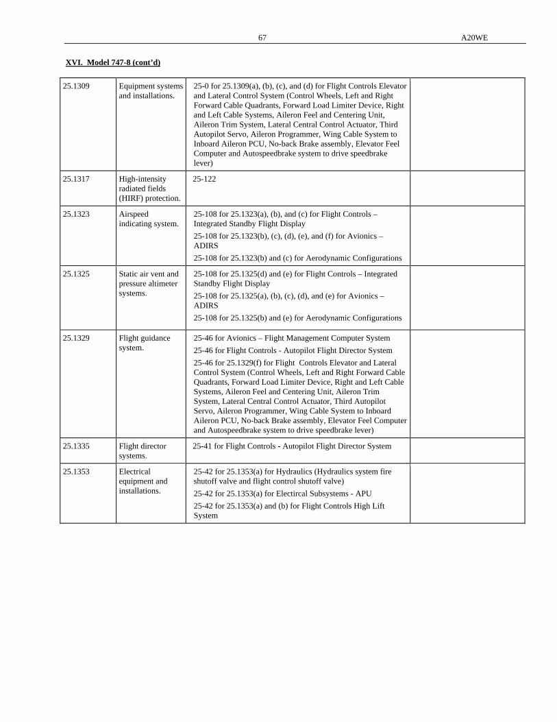
67 A20WE
XVI. Model 747-8 (cont’d)
25.1309 Equipment systems and installations.
25-0 for 25.1309(a), (b), (c), and (d) for Flight Controls Elevator and Lateral Control System (Control Wheels, Left and Right Forward Cable Quadrants, Forward Load Limiter Device, Right and Left Cable Systems, Aileron Feel and Centering Unit, Aileron Trim System, Lateral Central Control Actuator, Third Autopilot Servo, Aileron Programmer, Wing Cable System to Inboard Aileron PCU, No-back Brake assembly, Elevator Feel Computer and Autospeedbrake system to drive speedbrake lever)
25.1317 High-intensity radiated fields (HIRF) protection.
25-122
25.1323 Airspeed indicating system.
25-108 for 25.1323(a), (b), and (c) for Flight Controls – Integrated Standby Flight Display
25-108 for 25.1323(b), (c), (d), (e), and (f) for Avionics – ADIRS
25-108 for 25.1323(b) and (c) for Aerodynamic Configurations
25.1325 Static air vent and pressure altimeter systems.
25-108 for 25.1325(d) and (e) for Flight Controls – Integrated Standby Flight Display
25-108 for 25.1325(a), (b), (c), (d), and (e) for Avionics – ADIRS
25-108 for 25.1325(b) and (e) for Aerodynamic Configurations
25.1329 Flight guidance system.
25-46 for Avionics – Flight Management Computer System
25-46 for Flight Controls - Autopilot Flight Director System
25-46 for 25.1329(f) for Flight Controls Elevator and Lateral Control System (Control Wheels, Left and Right Forward Cable Quadrants, Forward Load Limiter Device, Right and Left Cable Systems, Aileron Feel and Centering Unit, Aileron Trim System, Lateral Central Control Actuator, Third Autopilot Servo, Aileron Programmer, Wing Cable System to Inboard Aileron PCU, No-back Brake assembly, Elevator Feel Computer and Autospeedbrake system to drive speedbrake lever)
25.1335 Flight director systems.
25-41 for Flight Controls - Autopilot Flight Director System
25.1353 Electrical equipment and installations.
25-42 for 25.1353(a) for Hydraulics (Hydraulics system fire shutoff valve and flight control shutoff valve)
25-42 for 25.1353(a) for Electircal Subsystems - APU
25-42 for 25.1353(a) and (b) for Flight Controls High Lift System
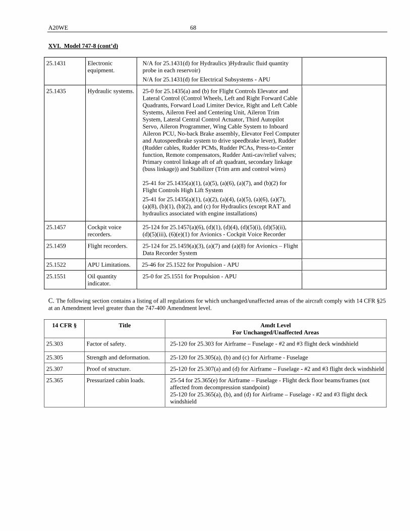
A20WE 68
XVI. Model 747-8 (cont’d)
25.1431 Electronic equipment.
N/A for 25.1431(d) for Hydraulics )Hydraulic fluid quantity probe in each reservoir)
N/A for 25.1431(d) for Electrical Subsystems - APU
25.1435 Hydraulic systems. 25-0 for 25.1435(a) and (b) for Flight Controls Elevator and Lateral Control (Control Wheels, Left and Right Forward Cable Quadrants, Forward Load Limiter Device, Right and Left Cable Systems, Aileron Feel and Centering Unit, Aileron Trim System, Lateral Central Control Actuator, Third Autopilot Servo, Aileron Programmer, Wing Cable System to Inboard Aileron PCU, No-back Brake assembly, Elevator Feel Computer and Autospeedbrake system to drive speedbrake lever), Rudder (Rudder cables, Rudder PCMs, Rudder PCAs, Press-to-Center function, Remote compensators, Rudder Anti-cav/relief valves; Primary control linkage aft of aft quadrant, secondary linkage (buss linkage)) and Stabilizer (Trim arm and control wires) 25-41 for 25.1435(a)(1), (a)(5), (a)(6), (a)(7), and (b)(2) for Flight Controls High Lift System
25-41 for 25.1435(a)(1), (a)(2), (a)(4), (a)(5), (a)(6), (a)(7), (a)(8), (b)(1), (b)(2), and (c) for Hydraulics (except RAT and hydraulics associated with engine installations)
25.1457 Cockpit voice recorders.
25-124 for 25.1457(a)(6), (d)(1), (d)(4), (d)(5)(i), (d)(5)(ii), (d)(5)(iii), (6)(e)(1) for Avionics - Cockpit Voice Recorder
25.1459 Flight recorders. 25-124 for 25.1459(a)(3), (a)(7) and (a)(8) for Avionics – Flight Data Recorder System
25.1522 APU Limitations. 25-46 for 25.1522 for Propulsion - APU
25.1551 Oil quantity indicator.
25-0 for 25.1551 for Propulsion - APU
C. The following section contains a listing of all regulations for which unchanged/unaffected areas of the aircraft comply with 14 CFR §25 at an Amendment level greater than the 747-400 Amendment level.
14 CFR § Title Amdt Level For Unchanged/Unaffected Areas
25.303 Factor of safety. 25-120 for 25.303 for Airframe – Fuselage - #2 and #3 flight deck windshield
25.305 Strength and deformation. 25-120 for 25.305(a), (b) and (c) for Airframe - Fuselage
25.307 Proof of structure. 25-120 for 25.307(a) and (d) for Airframe – Fuselage - #2 and #3 flight deck windshield
25.365 Pressurized cabin loads. 25-54 for 25.365(e) for Airframe – Fuselage - Flight deck floor beams/frames (not affected from decompression standpoint) 25-120 for 25.365(a), (b), and (d) for Airframe – Fuselage - #2 and #3 flight deck windshield
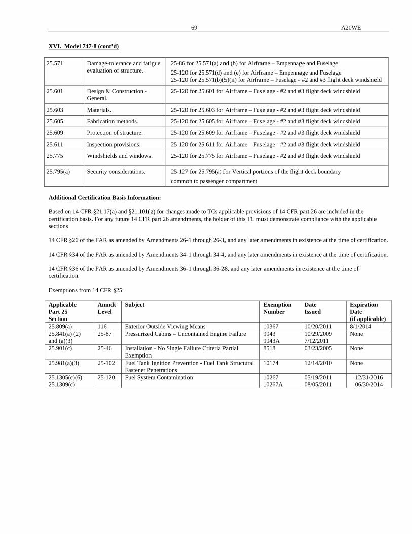
69 A20WE
XVI. Model 747-8 (cont’d)
25.571 Damage-tolerance and fatigue evaluation of structure.
25-86 for 25.571(a) and (b) for Airframe – Empennage and Fuselage
25-120 for 25.571(d) and (e) for Airframe – Empennage and Fuselage 25-120 for 25.571(b)(5)(ii) for Airframe – Fuselage - #2 and #3 flight deck windshield
25.601 Design & Construction - General.
25-120 for 25.601 for Airframe – Fuselage - #2 and #3 flight deck windshield
25.603 Materials. 25-120 for 25.603 for Airframe – Fuselage - #2 and #3 flight deck windshield
25.605 Fabrication methods. 25-120 for 25.605 for Airframe – Fuselage - #2 and #3 flight deck windshield
25.609 Protection of structure. 25-120 for 25.609 for Airframe – Fuselage - #2 and #3 flight deck windshield
25.611 Inspection provisions. 25-120 for 25.611 for Airframe – Fuselage - #2 and #3 flight deck windshield
25.775 Windshields and windows. 25-120 for 25.775 for Airframe – Fuselage - #2 and #3 flight deck windshield
25.795(a) Security considerations. 25-127 for 25.795(a) for Vertical portions of the flight deck boundary
common to passenger compartment
Additional Certification Basis Information: Based on 14 CFR §21.17(a) and §21.101(g) for changes made to TCs applicable provisions of 14 CFR part 26 are included in the certification basis. For any future 14 CFR part 26 amendments, the holder of this TC must demonstrate compliance with the applicable sections 14 CFR §26 of the FAR as amended by Amendments 26-1 through 26-3, and any later amendments in existence at the time of certification. 14 CFR §34 of the FAR as amended by Amendments 34-1 through 34-4, and any later amendments in existence at the time of certification. 14 CFR §36 of the FAR as amended by Amendments 36-1 through 36-28, and any later amendments in existence at the time of certification. Exemptions from 14 CFR §25: Applicable Part 25 Section
Amndt Level
Subject Exemption Number
Date Issued
Expiration Date (if applicable)
25.809(a) 116 Exterior Outside Viewing Means 10367 10/20/2011 8/1/2014 25.841(a) (2) and (a)(3)
25-87 Pressurized Cabins – Uncontained Engine Failure 9943 9943A
10/29/2009 7/12/2011
None
25.901(c) 25-46 Installation - No Single Failure Criteria Partial Exemption
8518 03/23/2005 None
25.981(a)(3) 25-102 Fuel Tank Ignition Prevention - Fuel Tank Structural Fastener Penetrations
10174 12/14/2010 None
25.1305(c)(6) 25.1309(c)
25-120 Fuel System Contamination 10267 10267A
05/19/2011 08/05/2011
12/31/2016 06/30/2014
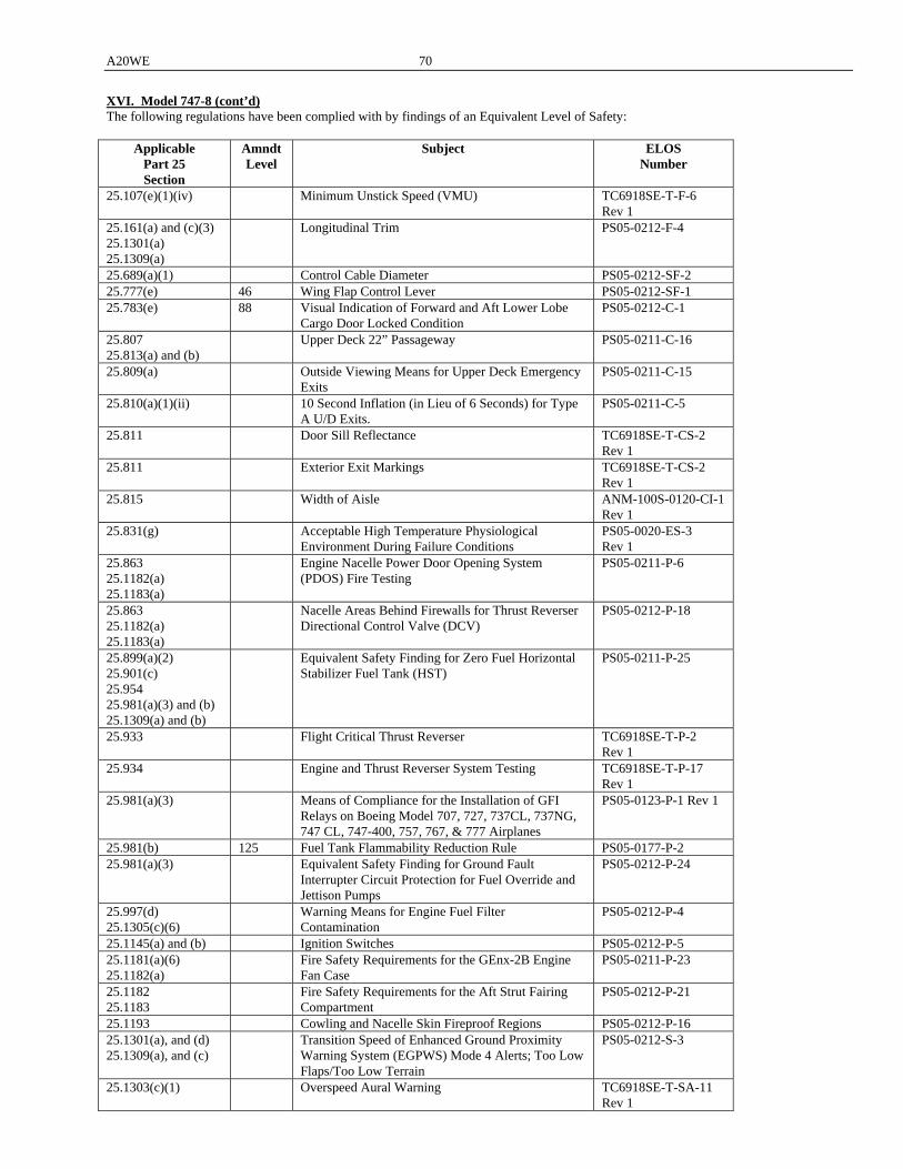
A20WE 70
XVI. Model 747-8 (cont’d) The following regulations have been complied with by findings of an Equivalent Level of Safety:
Applicable Part 25 Section
Amndt Level
Subject ELOS Number
25.107(e)(1)(iv) Minimum Unstick Speed (VMU) TC6918SE-T-F-6 Rev 1
25.161(a) and (c)(3) 25.1301(a) 25.1309(a)
Longitudinal Trim PS05-0212-F-4
25.689(a)(1) Control Cable Diameter PS05-0212-SF-2 25.777(e) 46 Wing Flap Control Lever PS05-0212-SF-1 25.783(e) 88 Visual Indication of Forward and Aft Lower Lobe
Cargo Door Locked Condition PS05-0212-C-1
25.807 25.813(a) and (b)
Upper Deck 22” Passageway PS05-0211-C-16
25.809(a) Outside Viewing Means for Upper Deck Emergency Exits
PS05-0211-C-15
25.810(a)(1)(ii) 10 Second Inflation (in Lieu of 6 Seconds) for Type A U/D Exits.
PS05-0211-C-5
25.811 Door Sill Reflectance TC6918SE-T-CS-2 Rev 1
25.811 Exterior Exit Markings TC6918SE-T-CS-2 Rev 1
25.815 Width of Aisle ANM-100S-0120-CI-1 Rev 1
25.831(g) Acceptable High Temperature Physiological Environment During Failure Conditions
PS05-0020-ES-3 Rev 1
25.863 25.1182(a) 25.1183(a)
Engine Nacelle Power Door Opening System (PDOS) Fire Testing
PS05-0211-P-6
25.863 25.1182(a) 25.1183(a)
Nacelle Areas Behind Firewalls for Thrust Reverser Directional Control Valve (DCV)
PS05-0212-P-18
25.899(a)(2) 25.901(c) 25.954 25.981(a)(3) and (b) 25.1309(a) and (b)
Equivalent Safety Finding for Zero Fuel Horizontal Stabilizer Fuel Tank (HST)
PS05-0211-P-25
25.933 Flight Critical Thrust Reverser TC6918SE-T-P-2 Rev 1
25.934 Engine and Thrust Reverser System Testing TC6918SE-T-P-17 Rev 1
25.981(a)(3) Means of Compliance for the Installation of GFI Relays on Boeing Model 707, 727, 737CL, 737NG, 747 CL, 747-400, 757, 767, & 777 Airplanes
PS05-0123-P-1 Rev 1
25.981(b) 125 Fuel Tank Flammability Reduction Rule PS05-0177-P-2 25.981(a)(3) Equivalent Safety Finding for Ground Fault
Interrupter Circuit Protection for Fuel Override and Jettison Pumps
PS05-0212-P-24
25.997(d) 25.1305(c)(6)
Warning Means for Engine Fuel Filter Contamination
PS05-0212-P-4
25.1145(a) and (b) Ignition Switches PS05-0212-P-5 25.1181(a)(6) 25.1182(a)
Fire Safety Requirements for the GEnx-2B Engine Fan Case
PS05-0211-P-23
25.1182 25.1183
Fire Safety Requirements for the Aft Strut Fairing Compartment
PS05-0212-P-21
25.1193 Cowling and Nacelle Skin Fireproof Regions PS05-0212-P-16 25.1301(a), and (d) 25.1309(a), and (c)
Transition Speed of Enhanced Ground Proximity Warning System (EGPWS) Mode 4 Alerts; Too Low Flaps/Too Low Terrain
PS05-0212-S-3
25.1303(c)(1) Overspeed Aural Warning TC6918SE-T-SA-11 Rev 1

71 A20WE
XVI. Model 747-8 (cont’d) 25.1325(e) Standby Air Data System PS05-0212-F-3 25.1415(c) Remote Stowage of Door 1 Slide/Raft Survival Kits PS05-0211-C-9 25.1435(b)(1) 104 Request for an Equivalent Level of Safety Finding
for the Hydraulic System Pressure Test PS05-0212-SF-4
25.1517 Rough Air Speed (VRA) TC6918SE-T-F-4 Rev 1
25.1529 Appendix H
Maintenance Planning Document Section 9 (Instructions for Continued Airworthiness)
PS05-0212-P-G-8
Note: The 777F issue paper ES-3, stage 4, “Acceptable High Temperature Physiological Environment During Failure Conditions,” signed January 18, 2008 references the July 31, 2003 version of the Mechanical Systems Harmonization Working Group (MSHWG) final report on § 25.831(g). The Actual version of the MSHWG final report approved unanimously by the Transport Airplane Engine Issues Group (TAEIG) was dated July 24, 2003. The draft rule, transient heat analysis, and body core limits are the same in the July 24, 2003 and July 31, 2003 versions of the MSHWG final report. Compliance findings should reference the July 24, 2003 version of the MSHWG final report on § 25.831(g). Special Conditions with respect to the following subjects apply to the 747-8:
Special Condition Number
Effective Date
Subject
25-ANM-24 12/21/1988 Flight Deck Displays and Propulsion Control Systems 25-368-SC 03/17/2008 Seats with Non-Traditional, Large, Non-Metallic Panels 25-385-SC 11/09/2009 Structural Design Requirements for Four-Post Main Landing Gear
System 25-387-SC 09/11/2009 Additional Airframe Structural Design Requirements Related to
Sudden Engine Stoppage Due to Fan Blade Failures 25-388A-SC 06/27/2011 Interaction of Systems and Structures 25-401-SC 02/16/2010 Systems and Data Networks Security--Protection of Airplane
Systems and Data Networks From Unauthorized External Access 25-402-SC 02/16/2010 Design Roll Maneuver Requirement 25-421-SC 03/09/2011 Security Protection of Aircraft Control Domain and Airline
Information Domain from the Passenger Entertainment Domain 25-430-SC 07/01/2011 Stairwell Between the Main and Upper Decks 25-438-SC 08/01/2011 Door 1 Extendable Length Escape Slide 25-442-SC 08/24/2011 Overhead Flight Attendant Rest Compartment 25-446-SC 09/28/2011 Upper Deck Occupancy
Additional Design Requirements and Conditions: The following design details or information must be maintained to ensure that an unsafe design condition is not present: 14 CFR 25.1329 – Flight Guidance System
The following design features must be incorporated in the type design (reference § 25.1329, Amendment 25-46). In lieu of the following, compliance to 25.1329, Amendment 25-119, may be shown.
1. Quick autopilot disconnect switches for each pilot on the outboard arm of each control wheel and quick autothrust disconnect switches for each pilot on the underside of the thrust control levers for engines 1 and 4.
2. Positive disconnect function for the autopilot is provided by the disconnect bar located at the glare shield on the autopilot mode control panel (MCP).
3. Positive disconnect function for the autothrottle is provided by the autothrottle arm switch, also located on the MCP.
4. Automatic synchronization of the autopilot and autothrust functions is provided in order to ensure transient free engagement and mode switching.
5. Automatic stabilizer trim is used to offload the elevator in order to ensure transient free disengagement of the autopilot pitch axis.
6. The wheel position provides a visual and tactile indication of any wheel input which may be required at disengagement of the autopilot roll axis.
7. When multiple autopilot channels are engaged, disengagement of an individual autopilot does not result in a transient any greater than a minor transient.
8. The throttle levers remain in the current position when the autothrust function is disengaged.
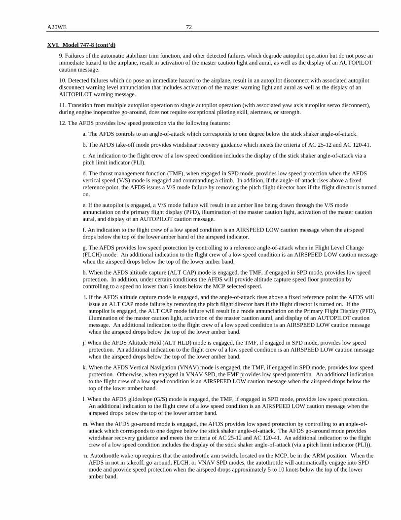
A20WE 72
XVI. Model 747-8 (cont’d)
9. Failures of the automatic stabilizer trim function, and other detected failures which degrade autopilot operation but do not pose an immediate hazard to the airplane, result in activation of the master caution light and aural, as well as the display of an AUTOPILOT caution message.
10. Detected failures which do pose an immediate hazard to the airplane, result in an autopilot disconnect with associated autopilot disconnect warning level annunciation that includes activation of the master warning light and aural as well as the display of an AUTOPILOT warning message.
11. Transition from multiple autopilot operation to single autopilot operation (with associated yaw axis autopilot servo disconnect), during engine inoperative go-around, does not require exceptional piloting skill, alertness, or strength.
12. The AFDS provides low speed protection via the following features:
a. The AFDS controls to an angle-of-attack which corresponds to one degree below the stick shaker angle-of-attack.
b. The AFDS take-off mode provides windshear recovery guidance which meets the criteria of AC 25-12 and AC 120-41.
c. An indication to the flight crew of a low speed condition includes the display of the stick shaker angle-of-attack via a pitch limit indicator (PLI).
d. The thrust management function (TMF), when engaged in SPD mode, provides low speed protection when the AFDS vertical speed (V/S) mode is engaged and commanding a climb. In addition, if the angle-of-attack rises above a fixed reference point, the AFDS issues a V/S mode failure by removing the pitch flight director bars if the flight director is turned on.
e. If the autopilot is engaged, a V/S mode failure will result in an amber line being drawn through the V/S mode annunciation on the primary flight display (PFD), illumination of the master caution light, activation of the master caution aural, and display of an AUTOPILOT caution message.
f. An indication to the flight crew of a low speed condition is an AIRSPEED LOW caution message when the airspeed drops below the top of the lower amber band of the airspeed indicator.
g. The AFDS provides low speed protection by controlling to a reference angle-of-attack when in Flight Level Change (FLCH) mode. An additional indication to the flight crew of a low speed condition is an AIRSPEED LOW caution message when the airspeed drops below the top of the lower amber band.
h. When the AFDS altitude capture (ALT CAP) mode is engaged, the TMF, if engaged in SPD mode, provides low speed protection. In addition, under certain conditions the AFDS will provide altitude capture speed floor protection by controlling to a speed no lower than 5 knots below the MCP selected speed.
i. If the AFDS altitude capture mode is engaged, and the angle-of-attack rises above a fixed reference point the AFDS will issue an ALT CAP mode failure by removing the pitch flight director bars if the flight director is turned on. If the autopilot is engaged, the ALT CAP mode failure will result in a mode annunciation on the Primary Flight Display (PFD), illumination of the master caution light, activation of the master caution aural, and display of an AUTOPILOT caution message. An additional indication to the flight crew of a low speed condition is an AIRSPEED LOW caution message when the airspeed drops below the top of the lower amber band.
j. When the AFDS Altitude Hold (ALT HLD) mode is engaged, the TMF, if engaged in SPD mode, provides low speed protection. An additional indication to the flight crew of a low speed condition is an AIRSPEED LOW caution message when the airspeed drops below the top of the lower amber band.
k. When the AFDS Vertical Navigation (VNAV) mode is engaged, the TMF, if engaged in SPD mode, provides low speed protection. Otherwise, when engaged in VNAV SPD, the FMF provides low speed protection. An additional indication to the flight crew of a low speed condition is an AIRSPEED LOW caution message when the airspeed drops below the top of the lower amber band.
l. When the AFDS glideslope (G/S) mode is engaged, the TMF, if engaged in SPD mode, provides low speed protection. An additional indication to the flight crew of a low speed condition is an AIRSPEED LOW caution message when the airspeed drops below the top of the lower amber band.
m. When the AFDS go-around mode is engaged, the AFDS provides low speed protection by controlling to an angle-of-attack which corresponds to one degree below the stick shaker angle-of-attack. The AFDS go-around mode provides windshear recovery guidance and meets the criteria of AC 25-12 and AC 120-41. An additional indication to the flight crew of a low speed condition includes the display of the stick shaker angle-of-attack (via a pitch limit indicator (PLI)).
n. Autothrottle wake-up requires that the autothrottle arm switch, located on the MCP, be in the ARM position. When the AFDS in not in takeoff, go-around, FLCH, or VNAV SPD modes, the autothrottle will automatically engage into SPD mode and provide speed protection when the airspeed drops approximately 5 to 10 knots below the top of the lower amber band.
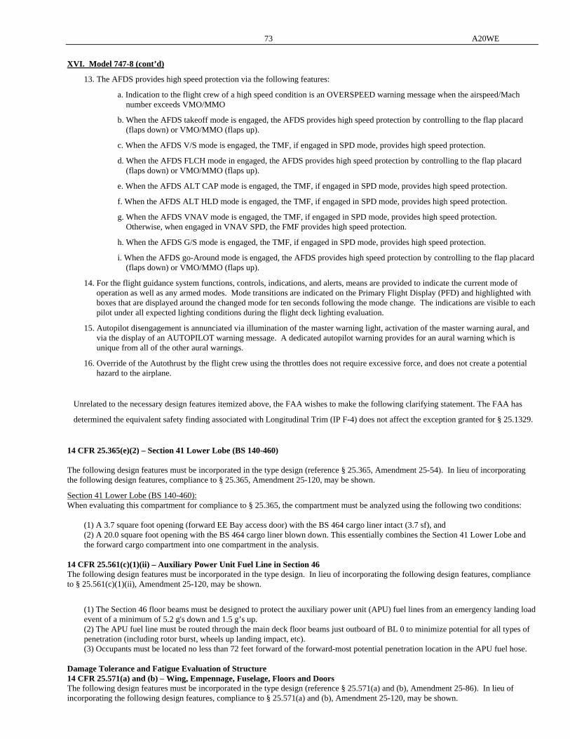
73 A20WE
XVI. Model 747-8 (cont’d)
13. The AFDS provides high speed protection via the following features:
a. Indication to the flight crew of a high speed condition is an OVERSPEED warning message when the airspeed/Mach number exceeds VMO/MMO
b. When the AFDS takeoff mode is engaged, the AFDS provides high speed protection by controlling to the flap placard (flaps down) or VMO/MMO (flaps up).
c. When the AFDS V/S mode is engaged, the TMF, if engaged in SPD mode, provides high speed protection.
d. When the AFDS FLCH mode in engaged, the AFDS provides high speed protection by controlling to the flap placard (flaps down) or VMO/MMO (flaps up).
e. When the AFDS ALT CAP mode is engaged, the TMF, if engaged in SPD mode, provides high speed protection.
f. When the AFDS ALT HLD mode is engaged, the TMF, if engaged in SPD mode, provides high speed protection.
g. When the AFDS VNAV mode is engaged, the TMF, if engaged in SPD mode, provides high speed protection. Otherwise, when engaged in VNAV SPD, the FMF provides high speed protection.
h. When the AFDS G/S mode is engaged, the TMF, if engaged in SPD mode, provides high speed protection.
i. When the AFDS go-Around mode is engaged, the AFDS provides high speed protection by controlling to the flap placard (flaps down) or VMO/MMO (flaps up).
14. For the flight guidance system functions, controls, indications, and alerts, means are provided to indicate the current mode of operation as well as any armed modes. Mode transitions are indicated on the Primary Flight Display (PFD) and highlighted with boxes that are displayed around the changed mode for ten seconds following the mode change. The indications are visible to each pilot under all expected lighting conditions during the flight deck lighting evaluation.
15. Autopilot disengagement is annunciated via illumination of the master warning light, activation of the master warning aural, and via the display of an AUTOPILOT warning message. A dedicated autopilot warning provides for an aural warning which is unique from all of the other aural warnings.
16. Override of the Autothrust by the flight crew using the throttles does not require excessive force, and does not create a potential hazard to the airplane.
Unrelated to the necessary design features itemized above, the FAA wishes to make the following clarifying statement. The FAA has
determined the equivalent safety finding associated with Longitudinal Trim (IP F-4) does not affect the exception granted for § 25.1329.
14 CFR 25.365(e)(2) – Section 41 Lower Lobe (BS 140-460) The following design features must be incorporated in the type design (reference § 25.365, Amendment 25-54). In lieu of incorporating the following design features, compliance to § 25.365, Amendment 25-120, may be shown.
Section 41 Lower Lobe (BS 140-460): When evaluating this compartment for compliance to § 25.365, the compartment must be analyzed using the following two conditions: (1) A 3.7 square foot opening (forward EE Bay access door) with the BS 464 cargo liner intact (3.7 sf), and (2) A 20.0 square foot opening with the BS 464 cargo liner blown down. This essentially combines the Section 41 Lower Lobe and
the forward cargo compartment into one compartment in the analysis. 14 CFR 25.561(c)(1)(ii) – Auxiliary Power Unit Fuel Line in Section 46 The following design features must be incorporated in the type design. In lieu of incorporating the following design features, compliance to § 25.561(c)(1)(ii), Amendment 25-120, may be shown.
(1) The Section 46 floor beams must be designed to protect the auxiliary power unit (APU) fuel lines from an emergency landing load
event of a minimum of 5.2 g's down and 1.5 g’s up. (2) The APU fuel line must be routed through the main deck floor beams just outboard of BL 0 to minimize potential for all types of
penetration (including rotor burst, wheels up landing impact, etc). (3) Occupants must be located no less than 72 feet forward of the forward-most potential penetration location in the APU fuel hose. Damage Tolerance and Fatigue Evaluation of Structure 14 CFR 25.571(a) and (b) – Wing, Empennage, Fuselage, Floors and Doors The following design features must be incorporated in the type design (reference § 25.571(a) and (b), Amendment 25-86). In lieu of incorporating the following design features, compliance to § 25.571(a) and (b), Amendment 25-120, may be shown.

A20WE 74
XVI. Model 747-8 (cont’d)
(1) For the 747-8 structure, an evaluation of the existing damage tolerance analysis (DTA) inspection program identified in the Supplemental Structural Inspection Document (SSID) must be performed for any required changes due to loads, geometry changes, material changes, etc. The resulting inspection requirements for the 747-8 must be included in Section 9 (Airworthiness Limitations) of the Boeing Maintenance Planning Document (MPD) D621U400 in accordance with § 25.571(a)(3) at Amendment 25-120.
(2) The above evaluation must include loading magnitudes and loading spectra which are developed in accordance with § 25.571 at Amendment 25-120. This includes usage of the 1.15 factor for pressure acting alone in accordance with § 25.571(b)(5) at Amendment 25-120.
(3) Maintenance instructions must be based on in-service data and fatigue testing to ensure freedom from widespread fatigue damage.
Production Basis: Production Certificate No. 700 has been issued to The Boeing Company.
Equipment: The basic required equipment as prescribed in the applicable airworthiness regulations (see Certification Basis) must be
installed in the aircraft for certification.
NOTES APPLICABLE TO SECTION XV MODEL 747-8F and SECTION XVI MODEL 747-8 ONLY: NOTE 1. A current Weight and Balance Manual including a list of equipment included in the certificated empty weight and loading
instructions must be in each aircraft at the time of original airworthiness certification and at all times thereafter except in the case of an operator having an approved weight control system.
NOTE 2. Airplane operation must be in accordance with the FAA Approved Airplane Flight Manual. All placards required by either
the FAA Approved Airplane Flight Manual, the applicable operating rules or the certification basis must be installed in the airplane.
NOTE 3 The FAA approved Airworthiness Limitations Section of the Instructions for Continued Airworthiness are referenced in
Maintenance Planning Data Document (MPD) Section 9 - Airworthiness Limitations and Certification Maintenance Requirements; Boeing Document D011U721-02. The Airworthiness Limitations section is FAA-approved and specifies maintenance required under 14 CFR 43.16 and 91.403 of the Federal Aviation Regulations, unless an alternative program has been FAA approved. The following documents are the FAA approved requirements to comply with 14 CFR 25.1529, 43.16 and 91.403:
D011U721-02-01, 747-8/8F Airworthiness Limitations (AWLs) D011U721-02-02, 747-8/8F Airworthiness Limitations (AWLs) - Line No. Specific D011U721-02-03, 747-8/8F Certification Maintenance Requirements (CMRs) D011U721-02-04, 747-8/8F Special Compliance Items (SCls)/Airworthiness Limitations
...-END-.....