Embed Size (px)
Citation preview
NAVY HANDBOOKOPNAV P-45-117-6-98
30 JUNE 1998
ELECTRICAL SAFETY FIELD GUIDE
DEPARTMENT OF THE NAVYTHIS PUBLICATION CONTAINS COPYRIGHTED MATERIAL
BY ORDER OF THE NAVY HANDBOOK 45-117-6-98SECRETARY OF THE NAVY 30 JUNE 98
ELECTRICAL SAFETY FIELD GUIDEThis handbook summarizes safety requirements
for electrical workers in the field.
Additional copies may be ordered, free of charge, from:Defense Distribution Depot, Susquehanna, Pennsylvania (500 copies)5450 Carlisle Pike, Building Number 5Mechanichsburg, Pennsylvania, 17055-0789Stock #: 0420-LP-010-6870
Index OPNAV P-45-117-6-98
ii
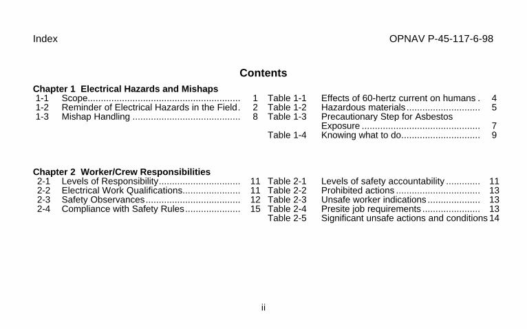
ContentsChapter 1 Electrical Hazards and Mishaps 1-1 Scope.......................................................... 1 1-2 Reminder of Electrical Hazards in the Field. 2 1-3 Mishap Handling ......................................... 8
Table 1-1 Effects of 60-hertz current on humans . 4Table 1-2 Hazardous materials ............................ 5Table 1-3 Precautionary Step for Asbestos
Exposure ............................................. 7Table 1-4 Knowing what to do.............................. 9
Chapter 2 Worker/Crew Responsibilities2-1 Levels of Responsibility............................... 112-2 Electrical Work Qualifications...................... 112-3 Safety Observances.................................... 122-4 Compliance with Safety Rules..................... 15
Table 2-1 Levels of safety accountability ............. 11Table 2-2 Prohibited actions ................................ 13Table 2-3 Unsafe worker indications .................... 13Table 2-4 Presite job requirements ...................... 13Table 2-5 Significant unsafe actions and conditions 14

Index OPNAV P-45-117-6-98
iii
Chapter 3 Presite Safety Management3-1 Work Area Aspects Affecting Safety............ 173-2 Electrical Aspects Affecting Safety .............. 233-3 Verifying System and Equipment Provisions 29
Table 3-1 Minimum illumination requirements ..... 18Table 3-2 Excavation pre-survey checklist........... 20Table 3-3 Excavation involving private utilities .... 21Table 3-4 Performing excavations ....................... 21Table 3-5 Backfilling............................................ 22Table 3-6 Damage during backfilling of trenching 22Table 3-7 Limits of approach ............................... 24Table 3-8 Qualified worker minimum working
Distances............................................. 25Table 3-9 Unqualified worker minimum approach
Distances............................................. 25Table 3-10 Jobs requiring two electrical workers.... 28Table 3-11 Jobs working in confined spaces
requiring additional workers ................. 28Table 3-12 Jobs generally acceptable for one
Electrical worker .................................. 29
Index OPNAV P-45-117-6-98
iv
Chapter 4 Personal Protective Equipment4-1 General Body Protection ............................. 304-2 Additional Worker Protection for Pole/
Tree Climbing and for Fall Protection .......... 31
Table 4-1 Apparel and body protectionrequirements........................................ 33
Table 4-2 Qualifications for climbing.................... 37Table 4-3 In-use check of pole climber gaffs........ 38
Chapter 5 Work Area Protective Equipment5-1 Temporary Protective Electrical Insulation .. 415-2 Energy Hazard Detection ............................ 48
Table 5-1 ASTM F 18 rubber goods..................... 42Table 5-2 Ladder inspections............................... 45Table 5-3 Proper care and storage of ladders ...... 45Table 5-4 Proper setup and use of ladders .......... 46
Chapter 6 De-Energized Line Clearance6-1 Safe Clearance Procedures......................... 506-2 Lockout/tagout/tryout Instructions ................ 516-3 Hazardous Energy Elimination .................... 51
Table 6-1 Sequence of lockout/tagout/tryoutsteps.................................................... 51
Table 6-2 Hazardous energy control .................... 52
Index OPNAV P-45-117-6-98
v
Chapter 7 De-Energized Line Grounding7-1 Grounding Provision.................................... 537-2 Why Temporary Grounds are Necessary..... 547-3 Equipotential (Single Point) Grounding........ 557-4 Placement of Grounds................................. 557-5 Temporary Grounding System
Components................................................ 577-6 Temporary Grounding of Aerial Lines .......... 607-7 Temporary Grounding of Substation
Current-Carrying Equipment Components ... 617-8 Aerial Lift Truck Vehicle Grounding ............. 657-9 Temporary Grounding of Underground
Lines ........................................................... 687-10 Opening or Splicing De-Energized
Conductors.................................................. 687-11 Grounding for Stringing and Removing
Lines ........................................................... 68
Table 7-1 Causes of hazardous inducedpotential differences ............................ 54
Table 7-2 Temporary grounding connection/removal procedure............................... 56
Table 7-3 Maximum fault current capability forgrounding cables ................................. 58
Table 7-4 Temporary ground rod minimumrequirements........................................ 59
Table 7-5 Substation protective groundingprocedures........................................... 63
Table 7-6 Grounding of substation equipment...... 64Table 7-7 Grounding of equipment during oil
handling............................................... 65Table 7-8 Procedures for grounding insulated
and uninsulated aerial lift trucks........... 66Table 7-9 Stringing/removing conductor ground
locations .............................................. 71Table 7-10 Conductor ground location after pulling 71
Index OPNAV P-45-117-6-98
vi
Chapter 8 Energized Line Work8-1 Normal Work Methods ................................ 738-2 Permitted Energized Line Work Methods .... 738-3 Voltage Levels and Approved Work
Methods and Equipment.............................. 748-4 Prework Procedures .................................... 798-5 General Job-in-Progress Procedures........... 80
Table 8-1 Categories of energized linemaintenance work ............................... 74
Table 8-2 Approved energized work methodsby voltage class................................... 75
Table 8-3 Insulating tools for electrical workers ... 76Table 8-4 Insulating plastic guards/platforms
for electrical workers............................ 77Table 8-5 Prework procedures............................. 79Table 8-6 Energized work precautions................. 80Table 8-7 Voltage level work procedures............. 81
Chapter 9 Substations and Switchgear9-1 Safety Precautions ...................................... 849-2 Major Equipment Hazards and Safety
Precautions ................................................. 84
Table 9-1 Major device important safety reminders 85
Index OPNAV P-45-117-6-98
vii
Chapter 10 Aerial Lines10-1 Safety Precautions ...................................... 8910-2 Climbing and Working on Poles .................. 8910-3 Aerial Rope Use .......................................... 90
Table 10-1 Pole climbing and working precautions 90
Chapter 11 Underground Lines11-1 Safety Precautions ...................................... 9111-2 Underground Structure Precautions............. 9211-3 Work in Underground Structures ................. 93
Table 11-1 Precautions before entering undergroundstructures ............................................ 92
Table 11-2 Precautions when working onunderground structures........................ 93
Table 11-3 Underground structure cable workprecautions.......................................... 94
Index OPNAV P-45-117-6-98
viii
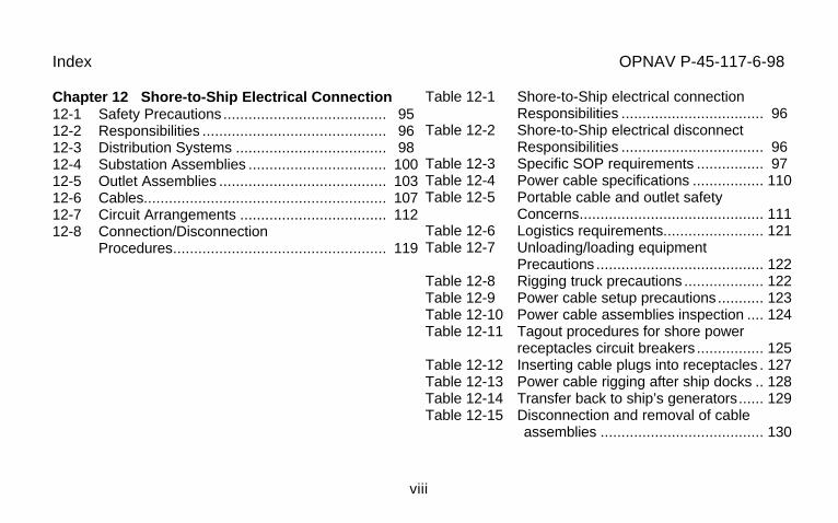
Chapter 12 Shore-to-Ship Electrical Connection12-1 Safety Precautions ....................................... 9512-2 Responsibilities ............................................ 9612-3 Distribution Systems .................................... 9812-4 Substation Assemblies ................................. 10012-5 Outlet Assemblies ........................................ 10312-6 Cables.......................................................... 10712-7 Circuit Arrangements ................................... 11212-8 Connection/Disconnection
Procedures................................................... 119
Table 12-1 Shore-to-Ship electrical connectionResponsibilities .................................. 96
Table 12-2 Shore-to-Ship electrical disconnectResponsibilities .................................. 96
Table 12-3 Specific SOP requirements ................ 97Table 12-4 Power cable specifications ................. 110Table 12-5 Portable cable and outlet safety
Concerns............................................ 111Table 12-6 Logistics requirements........................ 121Table 12-7 Unloading/loading equipment
Precautions ........................................ 122Table 12-8 Rigging truck precautions ................... 122Table 12-9 Power cable setup precautions........... 123Table 12-10 Power cable assemblies inspection .... 124Table 12-11 Tagout procedures for shore power
receptacles circuit breakers ................ 125Table 12-12 Inserting cable plugs into receptacles . 127Table 12-13 Power cable rigging after ship docks .. 128Table 12-14 Transfer back to ship’s generators...... 129Table 12-15 Disconnection and removal of cable
assemblies ....................................... 130
Index OPNAV P-45-117-6-98
ix
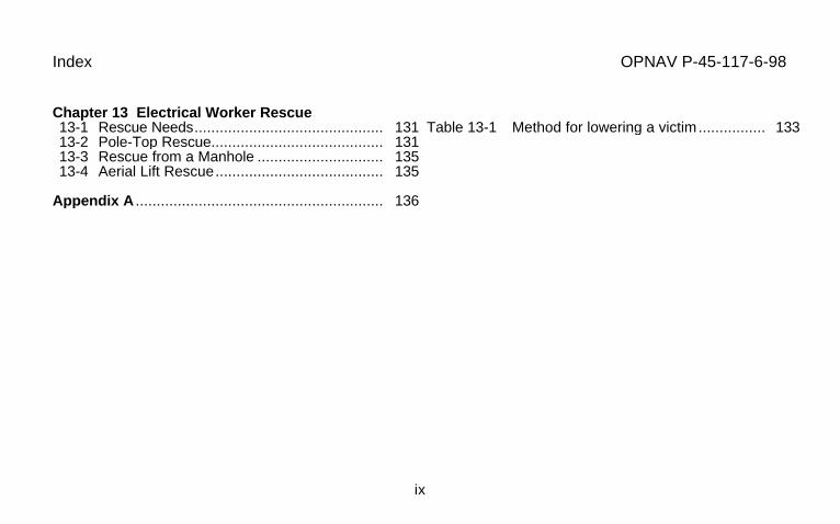
Chapter 13 Electrical Worker Rescue13-1 Rescue Needs............................................. 13113-2 Pole-Top Rescue......................................... 13113-3 Rescue from a Manhole .............................. 13513-4 Aerial Lift Rescue........................................ 135
Table 13-1 Method for lowering a victim................ 133
Appendix A ........................................................... 136

OPNAV P-45-117-6-98
Acknowledgment
The Navy wishes to express their sincere appreciation to the Air Force and theirrepresentatives (Mr. Raymond N. Hansen, P.E., HQ AFCESA/CESE) who kindly cooperated insupplying the original text (AFH 32-1011) of this handbook which has been modified to meetNavy applications.
Chapter 1. Electrical Hazards and Mishaps OPNAV P-45-117-6-98
1
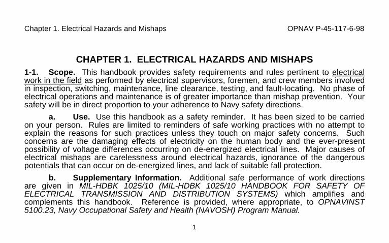
CHAPTER 1. ELECTRICAL HAZARDS AND MISHAPS1-1. Scope. This handbook provides safety requirements and rules pertinent to electricalwork in the field as performed by electrical supervisors, foremen, and crew members involvedin inspection, switching, maintenance, line clearance, testing, and fault-locating. No phase ofelectrical operations and maintenance is of greater importance than mishap prevention. Yoursafety will be in direct proportion to your adherence to Navy safety directions.
a. Use. Use this handbook as a safety reminder. It has been sized to be carriedon your person. Rules are limited to reminders of safe working practices with no attempt toexplain the reasons for such practices unless they touch on major safety concerns. Suchconcerns are the damaging effects of electricity on the human body and the ever-presentpossibility of voltage differences occurring on de-energized electrical lines. Major causes ofelectrical mishaps are carelessness around electrical hazards, ignorance of the dangerouspotentials that can occur on de-energized lines, and lack of suitable fall protection.
b. Supplementary Information. Additional safe performance of work directionsare given in MIL-HDBK 1025/10 (MIL-HDBK 1025/10 HANDBOOK FOR SAFETY OFELECTRICAL TRANSMISSION AND DISTRIBUTION SYSTEMS) which amplifies andcomplements this handbook. Reference is provided, where appropriate, to OPNAVINST5100.23, Navy Occupational Safety and Health (NAVOSH) Program Manual.
Chapter 1. Electrical Hazards and Mishaps OPNAV P-45-117-6-98
2
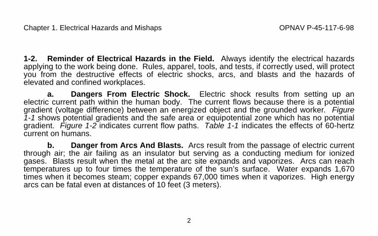
1-2. Reminder of Electrical Hazards in the Field. Always identify the electrical hazardsapplying to the work being done. Rules, apparel, tools, and tests, if correctly used, will protectyou from the destructive effects of electric shocks, arcs, and blasts and the hazards ofelevated and confined workplaces.
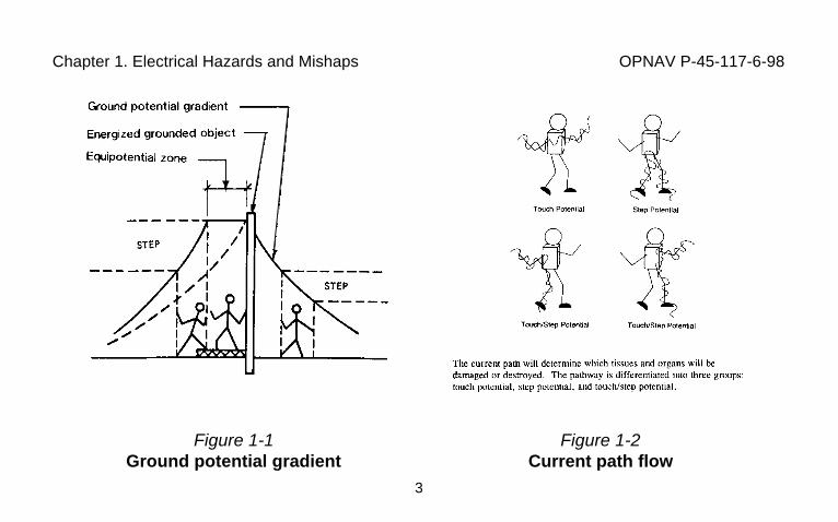
a. Dangers From Electric Shock. Electric shock results from setting up anelectric current path within the human body. The current flows because there is a potentialgradient (voltage difference) between an energized object and the grounded worker. Figure1-1 shows potential gradients and the safe area or equipotential zone which has no potentialgradient. Figure 1-2 indicates current flow paths. Table 1-1 indicates the effects of 60-hertzcurrent on humans.
b. Danger from Arcs And Blasts. Arcs result from the passage of electric currentthrough air; the air failing as an insulator but serving as a conducting medium for ionizedgases. Blasts result when the metal at the arc site expands and vaporizes. Arcs can reachtemperatures up to four times the temperature of the sun’s surface. Water expands 1,670times when it becomes steam; copper expands 67,000 times when it vaporizes. High energyarcs can be fatal even at distances of 10 feet (3 meters).
Chapter 1. Electrical Hazards and Mishaps OPNAV P-45-117-6-98
3
Figure 1-1Ground potential gradient
Figure 1-2Current path flow

Chapter 1. Electrical Hazards and Mishaps OPNAV P-45-117-6-98
4
Table 1-1. Effects of 60-hertz current on humansEffect Milliamperes
Men Women1
1. Slight sensation on hand ................................................................ 0.4................0.32. Perception threshold ...................................................................... 1.1................0.73. Shock, not painful and muscular control not lost............................ 1.8................1.24. Painful shock, painful but muscular control not lost ........................9 .................. 65. Painful shock let-go threshold .........................................................16 ...............10.56. Painful and severe shock, muscular contractions,
breathing difficult ......................................................................23 ................ 157. Ventricular fibrillation, threshold......................................................75 ................ 758. Ventricular fibrillation, fatal (usually fatal for shock
duration of 5 seconds or longer)..............................................235 .............. 2359. Heart paralysis (no ventricular fibrillation), threshold
(usually not fatal; heart often restarts after short shocks)...... 4,000............4,00010. Tissue burning (usually not fatal unless vital organs
damaged)............................................................................... 5,000............5,000
1The current values for women are lower because women typically have less body mass than men.
Chapter 1. Electrical Hazards and Mishaps OPNAV P-45-117-6-98
5
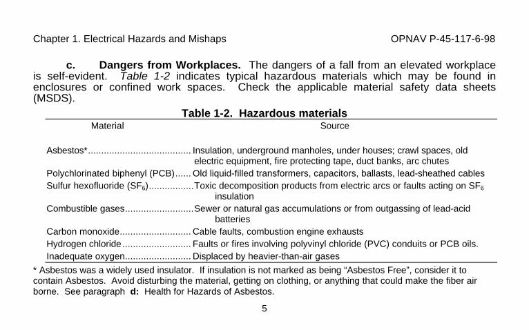
c. Dangers from Workplaces. The dangers of a fall from an elevated workplaceis self-evident. Table 1-2 indicates typical hazardous materials which may be found inenclosures or confined work spaces. Check the applicable material safety data sheets(MSDS).
Table 1-2. Hazardous materialsMaterial Source
Asbestos*....................................... Insulation, underground manholes, under houses; crawl spaces, oldelectric equipment, fire protecting tape, duct banks, arc chutes
Polychlorinated biphenyl (PCB)...... Old liquid-filled transformers, capacitors, ballasts, lead-sheathed cablesSulfur hexofluoride (SF6).................Toxic decomposition products from electric arcs or faults acting on SF6
insulationCombustible gases..........................Sewer or natural gas accumulations or from outgassing of lead-acid
batteriesCarbon monoxide........................... Cable faults, combustion engine exhaustsHydrogen chloride .......................... Faults or fires involving polyvinyl chloride (PVC) conduits or PCB oils.Inadequate oxygen......................... Displaced by heavier-than-air gases
* Asbestos was a widely used insulator. If insulation is not marked as being “Asbestos Free”, consider it tocontain Asbestos. Avoid disturbing the material, getting on clothing, or anything that could make the fiber airborne. See paragraph d: Health for Hazards of Asbestos.

Chapter 1. Electrical Hazards and Mishaps OPNAV P-45-117-6-98
6
d. Health Hazards of Asbestos: Asbestos is a known human carcinogen. It’sprimary route of entry to the body is by inhalation, however exposure can occur by ingestion.Asbestos is not absorbed through the skin. The diseases caused by long term exposure toasbestos are: cancer of the lungs, plura sack surrounding the lungs, bronchus, oropharynx,stomach, and colon.
Symptoms are shortness of breath, dry cough, and clubbing of the fingers.These symptoms generally do not show up for 20 years or more after initial exposure.
The potential for a material containing asbestos to release breathable fibersdepends on the material’s degree of friability. Friable means that the material can becrumbled with hand pressure. When working around materials suspected of containingasbestos, it is important not to bump, brush or disturb the materials in any way. Wetting thematerials can help to reduce the emission of fibers.
Chapter 1. Electrical Hazards and Mishaps OPNAV P-45-117-6-98
7
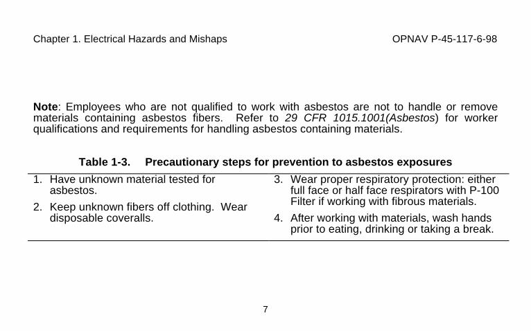
Note: Employees who are not qualified to work with asbestos are not to handle or removematerials containing asbestos fibers. Refer to 29 CFR 1015.1001(Asbestos) for workerqualifications and requirements for handling asbestos containing materials.
Table 1-3. Precautionary steps for prevention to asbestos exposures
1. Have unknown material tested forasbestos.
2. Keep unknown fibers off clothing. Weardisposable coveralls.
3. Wear proper respiratory protection: eitherfull face or half face respirators with P-100Filter if working with fibrous materials.
4. After working with materials, wash handsprior to eating, drinking or taking a break.
Chapter 1. Electrical Hazards and Mishaps OPNAV P-45-117-6-98
8
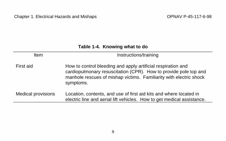
1-3. Mishap Handling. Each worker should know what to do when a mishap occurs.Additionally, each worker should know how to report injuries and other mishaps.
a. Knowing What To Do. First aid and cardiopulmonary resuscitation trainingrequirements for electrical workers. A medical professional must evaluate all shock victims forpossible immediate hospitalization. Table 1-4 summarizes the first aid knowledge required ofeach worker. As a preplanning aid, an emergency telephone number list should be preparedto include the location and telephone numbers of the nearest ambulance or emergencymedical treatment responders, the nearest hospital with an emergency room, the nearesthelicopter evacuation service, and the nearest burn trauma center.
Chapter 1. Electrical Hazards and Mishaps OPNAV P-45-117-6-98
9
Table 1-4. Knowing what to do
Item Instructions/training
First aid How to control bleeding and apply artificial respiration andcardiopulmonary resuscitation (CPR). How to provide pole top andmanhole rescues of mishap victims. Familiarity with electric shocksymptoms.
Medical provisions Location, contents, and use of first aid kits and where located inelectric line and aerial lift vehicles. How to get medical assistance.
Chapter 1. Electrical Hazards and Mishaps OPNAV P-45-117-6-98
10
b. Work Injuries and Mishap Reports. Report injuries, even minor ones, to yourimmediate supervisor in accordance with OPNAVINST 5100.23, (Navy Mishap Investigation,Reporting, and Recordkeeping Program) and NAVFACINST 5100.11. Additionally, everymishap involving personnel injury, property damage, or near misses must be investigated todetermine the cause and the corrective action needed to prevent recurrence. Cognizantsafety personnel conduct investigations. The safety staff must be notified of all mishaps thatinvolve personnel injuries or property damage.
Chapter 2. Worker/Crew Responsibilities OPNAV P-45-117-6-98
11
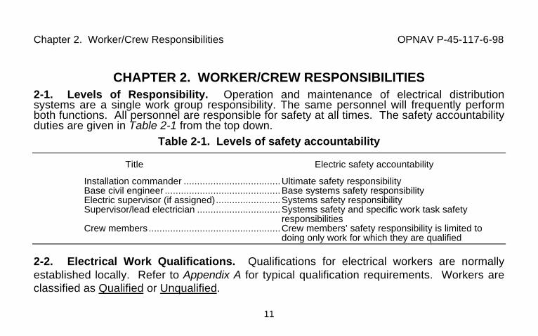
CHAPTER 2. WORKER/CREW RESPONSIBILITIES2-1. Levels of Responsibility. Operation and maintenance of electrical distributionsystems are a single work group responsibility. The same personnel will frequently performboth functions. All personnel are responsible for safety at all times. The safety accountabilityduties are given in Table 2-1 from the top down.
Table 2-1. Levels of safety accountability
Title Electric safety accountability
Installation commander ....................................Ultimate safety responsibilityBase civil engineer ...........................................Base systems safety responsibilityElectric supervisor (if assigned)........................Systems safety responsibilitySupervisor/lead electrician ...............................Systems safety and specific work task safety
responsibilitiesCrew members .................................................Crew members’ safety responsibility is limited to
doing only work for which they are qualified
2-2. Electrical Work Qualifications. Qualifications for electrical workers are normallyestablished locally. Refer to Appendix A for typical qualification requirements. Workers areclassified as Qualified or Unqualified.
Chapter 2. Worker/Crew Responsibilities OPNAV P-45-117-6-98
12
a. Qualified Workers. Persons who by training and demonstration are familiarwith the skills and techniques for: (1) distinguishing exposed live parts from other parts ofelectric equipment; (2) determining the nominal voltage of exposed live parts; and (3)maintaining minimum clearance distances corresponding to the voltages to which that personwill be exposed.
b. Unqualified Workers. Persons not meeting the requirements for QualifiedWorker. However, to be on the job these persons must be trained in all electrically relatedpractices that are necessary for their safety.
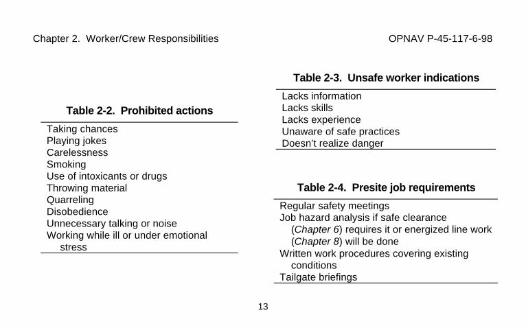
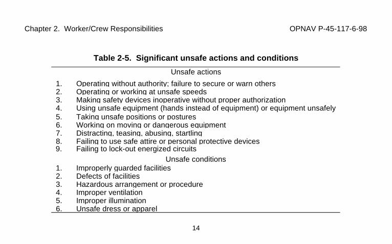
2-3. Safety Observances. Avoid prohibited actions (Table 2-2) and report unsafe workerindications (Table 2-3). Meet presite requirements (Table 2-4). Significant unsafe actionsand conditions are given in Table 2-5.
Chapter 2. Worker/Crew Responsibilities OPNAV P-45-117-6-98
13
Table 2-2. Prohibited actions
Taking chancesPlaying jokesCarelessnessSmokingUse of intoxicants or drugsThrowing materialQuarrelingDisobedienceUnnecessary talking or noiseWorking while ill or under emotional
stress
Table 2-3. Unsafe worker indications
Lacks informationLacks skillsLacks experienceUnaware of safe practicesDoesn’t realize danger
Table 2-4. Presite job requirements
Regular safety meetingsJob hazard analysis if safe clearance
(Chapter 6) requires it or energized line work(Chapter 8) will be done
Written work procedures covering existingconditions
Tailgate briefings
Chapter 2. Worker/Crew Responsibilities OPNAV P-45-117-6-98
14
Table 2-5. Significant unsafe actions and conditions
Unsafe actions
1. Operating without authority; failure to secure or warn others2. Operating or working at unsafe speeds3. Making safety devices inoperative without proper authorization4. Using unsafe equipment (hands instead of equipment) or equipment unsafely5. Taking unsafe positions or postures6. Working on moving or dangerous equipment7. Distracting, teasing, abusing, startling8. Failing to use safe attire or personal protective devices9. Failing to lock-out energized circuits
Unsafe conditions1. Improperly guarded facilities2. Defects of facilities3. Hazardous arrangement or procedure4. Improper ventilation5. Improper illumination6. Unsafe dress or apparel
Chapter 2. Worker/Crew Responsibilities OPNAV P-45-117-6-98
15
2-4. Compliance with Safety Rules. A requirement of employment is compliance with andknowledge of the rules in this handbook.
a. Enforcement. Supervisors and foremen are responsible for enforcing safetyrules and are subject to penalties for violations as are crew members.
b. Interpretation. In any case where rules are not clear a worker should ask theforeman or supervisor for an interpretation.
c. Violations. The severity of the penalty will be related to the seriousness of theoffense. Violations can range from a reprimand, layoff without pay, demotion, or discharge.Discharge is applicable to cases of deliberate or willful failure to observe written regulationswhenever such failure endangers the safety of persons or property.
Chapter 3. Presite Safety Management OPNAV P-45-117-6-98
17
CHAPTER 3. PRESITE SAFETY MANAGEMENT3-1. Work Area Aspects Affecting Safety. The location and the public access to the worksite impose additional protective or regulatory requirements.
a. Location of Work. The location of the work will determine whether climbing orconfined space training along with fall and/or respiratory protection are mandatory(see Chapter 4). Safety standards require protection from excessive noise and provision ofminimum illumination at any applicable work site.
(1) Noise. OPNAVINST 5100.23, (Hearing Conservation and NoiseAbatement Program) requires a listing of hazardous noise areas, physical boundaries, andconditions of required hearing protection and a monitoring program. Where hazardous noisearea signs are posted, hearing protection must be used as prescribed.
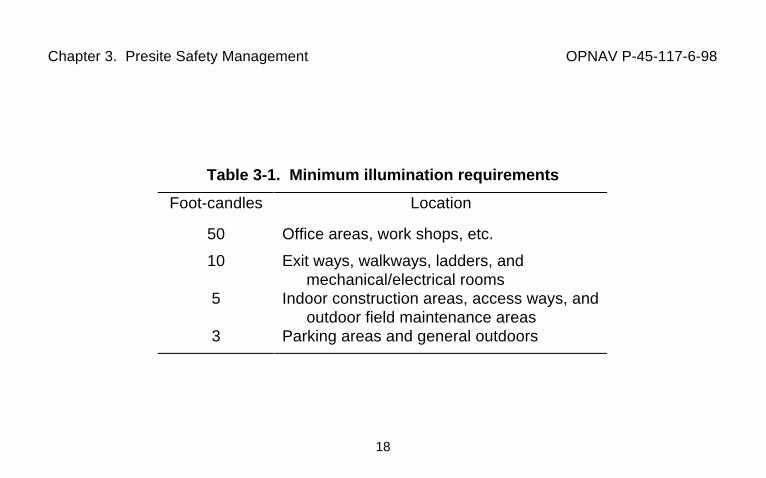
(2) Minimum Illumination. The minimum illumination for area safety is givenin Table 3-1. Additional illumination may be necessary dependent upon the work required.Generally additional illumination should only be needed for work in confined spaces and forwork approved for non-daylight hours.
Chapter 3. Presite Safety Management OPNAV P-45-117-6-98
18
Table 3-1. Minimum illumination requirements
Foot-candles Location
50 Office areas, work shops, etc.
10 Exit ways, walkways, ladders, andmechanical/electrical rooms
5 Indoor construction areas, access ways, andoutdoor field maintenance areas
3 Parking areas and general outdoors
Chapter 3. Presite Safety Management OPNAV P-45-117-6-98
19
b. Public Safety. Protect the public around the work area by safely guiding traffic awayfrom workers, equipment, and excavations.
(1) Warning Devices. Locate appropriate barriers, warning signs, trafficcones, and lights at approaches to and at work areas, excavations, open manholes, parkedequipment, and other hazards. Take special precautions for any areas where reducedvisibility occurs, such as night operations or in fog. Immediately remove warning devices afterremoval of hazards and equipment. Provide flagmen if there is any doubt as to whether thewarning devices will be adequate as controls, such as in areas with obstructed vehiculartraffic.
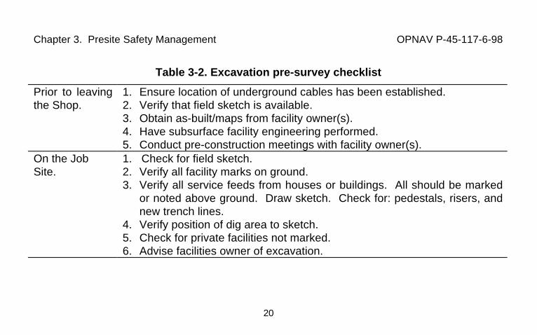
(2) Excavations. Provide barricades around every excavation area. Keepwarning barricade (cones, tape, and other items providing no physical protection) 5 feet (1.5meters) from the excavation. A protective barricade may be placed closer since it providesboth a warning and physical protection. Protective barricades must have a withstand rating ofat least 200 pounds (90 kilograms) in any direction with minimal deflection. Never enter anexcavation deeper than 4 feet which does not have a safe accessway, which has not beeninspected by a competent person before allowing an entrance, or which has equipmentworking next to the edge. Comply with requirements stated in 29 CFR 1926, Subpart P,(Excavations), and MIL-HDBK 1025/10 Handbook for Electrical Transmission and DistributionSafety,MIL-HDBK 1025/10. Always identify underground lines and services prior to startingexcavations.
Chapter 3. Presite Safety Management OPNAV P-45-117-6-98
20
Table 3-2. Excavation pre-survey checklist
Prior to leavingthe Shop.
1. Ensure location of underground cables has been established.2. Verify that field sketch is available.3. Obtain as-built/maps from facility owner(s).4. Have subsurface facility engineering performed.5. Conduct pre-construction meetings with facility owner(s).
On the JobSite.
1. Check for field sketch.2. Verify all facility marks on ground.3. Verify all service feeds from houses or buildings. All should be marked
or noted above ground. Draw sketch. Check for: pedestals, risers, andnew trench lines.
4. Verify position of dig area to sketch.5. Check for private facilities not marked.6. Advise facilities owner of excavation.
Chapter 3. Presite Safety Management OPNAV P-45-117-6-98
21
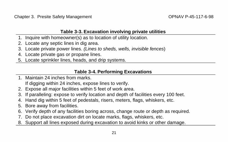
Table 3-3. Excavation involving private utilities1. Inquire with homeowner(s) as to location of utility location.2. Locate any septic lines in dig area.3. Locate private power lines. (Lines to sheds, wells, invisible fences)4. Locate private gas or propane lines.5. Locate sprinkler lines, heads, and drip systems.
Table 3-4. Performing Excavations1. Maintain 24 inches from marks.
If digging within 24 inches, expose lines to verify.2. Expose all major facilities within 5 feet of work area.3. If paralleling: expose to verify location and depth of facilities every 100 feet.4. Hand dig within 5 feet of pedestals, risers, meters, flags, whiskers, etc.5. Bore away from facilities.6. Verify depth of any facilities boring across, change route or depth as required.7. Do not place excavation dirt on locate marks, flags, whiskers, etc.8. Support all lines exposed during excavation to avoid kinks or other damage.
Chapter 3. Presite Safety Management OPNAV P-45-117-6-98
22
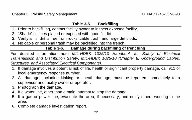
Table 3-5. Backfilling1. Prior to backfilling, contact facility owner to inspect exposed facility.2. “Shade” all lines placed or exposed with good fill dirt.3. Verify all fill dirt is free from rocks, cable trash, and large dirt clods.4. No cable or personal trash may be backfilled into the trench.
Table 3-6. Damage during backfilling of trenchingFor detailed information note MIL-HDBK 1025/10 Handbook for Safety of ElectricalTransmission and Distribution Safety, MIL-HDBK 1025/10 (Chapter 8; Underground Cables,Structures, and Associated Electrical Components).1. If damage involves a potential risk of life, health or significant property damage, call 911 or
local emergency response number.2. All damage, including kinking or sheath damage, must be reported immediately to a
supervisor and facility owner or operator.3. Photograph the damage.4. If a water line, other than a main, attempt to stop the damage.5. If a gas or power line, evacuate the area, if necessary, and notify others working in the
area.6. Complete damage investigation report.
Chapter 3. Presite Safety Management OPNAV P-45-117-6-98
23
3-2. Electrical Aspects Affecting Safety. Working on or near normally energized lines orparts requires observance of rules applying to safe working distances, work methods relatedto whether the line has been de-energized or left hot, and recognition of work hazards whichrequire more than one worker for safety.
a. Safe Working Distances. Only workers qualified by electrical training may workin areas on or with unguarded, uninsulated energized lines or parts of equipment operating at50 volts or more (see paragraph 2-2). All electric lines and equipment will be treated asenergized unless de-energized and grounded. Maintain the minimum clearances ofTables 3-7 and 3-8 based on the voltage range. See paragraph 8-3 for approved workmethods by voltage level.
Chapter 3. Presite Safety Management OPNAV P-45-117-6-98
24
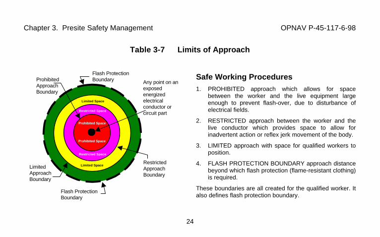
Table 3-7 Limits of Approach
Safe Working Procedures1. PROHIBITED approach which allows for space
between the worker and the live equipment largeenough to prevent flash-over, due to disturbance ofelectrical fields.
2. RESTRICTED approach between the worker and thelive conductor which provides space to allow forinadvertent action or reflex jerk movement of the body.
3. LIMITED approach with space for qualified workers toposition.
4. FLASH PROTECTION BOUNDARY approach distancebeyond which flash protection (flame-resistant clothing)is required.
These boundaries are all created for the qualified worker. Italso defines flash protection boundary.
Flash ProtectionBoundary Any point on an
exposedenergizedelectricalconductor orcircuit part
RestrictedApproachBoundary
Flash ProtectionBoundary
LimitedApproachBoundary
ProhibitedApproachBoundary
Limited Space
Limited Space
Restricted Space
Restricted Space
Prohibited Space
Prohibited Space

Chapter 3. Presite Safety Management OPNAV P-45-117-6-98
25
Table 3-8. Qualified worker minimum working distances1 2 3 4 5 6
Nominal System VoltageRange.
FlashProtectionBoundary
Limited ApproachBoundary
Minimum Working Distance 1
and Clear Hot Stick Distance 2
ProhibitedApproachBoundary
FromPhase to
PhaseVoltage
ExposedMovable
Conductor
ExposedFixed
Circuit Part
Includes Standard Inadvertent Movement Adder
IncludesReduced
InadvertentMovement
AdderPhase To Phase
3Phase To Ground
4
50 V to 300 V 3ft 0in 10ft 0in 3ft 6in Avoid Contact301 V to 750 V 3ft 0in 10ft 0in 3ft 6in 1ft 0in 1ft 0in 0ft 1in751 V to 2 kV 4ft 0in 10ft 0in 4ft 0in 2ft 3in 2ft 2in 0ft 3in2.001 kV to 15 kV 16ft 0in 10ft 0in 5ft 0in 2ft 3in 2ft 2in 0ft 7in15.001 kV to 36 kV 19ft 0in 10ft 0in 6ft 0in 2ft 10in 2ft 7in 0ft 10in36.001 kV to 48.3 kV 21ft 0in 10ft 0in 8ft 0in 2ft 10in 2ft 10in 1ft 5in1- Distance between energized parts and grounded objects without insulation, isolation, or guards.2- Between worker’s hand and working end of stick.3- Work on 3-phase delta systems, and on more than one phase of 3-phase wye systems.4- Work on single-phase systems, and work on one phase only of 3-phase wye systems.
Table 3-9. Unqualified worker minimum approach distancesVoltage to ground Distance50 kV or below 10 ft (3 m)
Chapter 3. Presite Safety Management OPNAV P-45-117-6-98
26
b. Work Methods In Relation To Workers’ Safety. All work will be done de-energized unless energized line work has been specifically authorized.
(1) De-energized Electrical Line Work. Follow the safe clearance(lockout/tagout/tryout) procedures given in Chapter 6. Remember lines are consideredenergized if the de-energized systems have not been provided with proper protectivegrounding (see Chapter 7).
(2) Energized Electrical Line Work. Work on energized lines and equipmentonly when written authorized by the Commanding Officer, Activity Civil Engineer, the PublicWorks Officer (PWO) or other designated authority (per local organization) based on the needto support a critical mission, to prevent injury to persons, or to protect property. Insulatingmeans must be provided to isolate workers from a source of potential difference along withwritten job specific operating procedures. When authorized, perform energized line work perChapter 8. Barehand liveline work is prohibited.
Chapter 3. Presite Safety Management OPNAV P-45-117-6-98
27
c. Number of Qualified Workers Per Hazard Exposure. 29 CFR 1910.269(Electrical power generation, transmission, and distribution) requires more than one workerwhere the hazard exposure of the work is considered to be significantly reduced by thepresence of additional workers. Tables 3-10 and 3-11 cover these requirements. Table 3-12indicates acceptable work where only one worker is needed. These tables indicate theminimum number of workers required. More workers may be necessary to provide safeworking conditions in some circumstances.
Chapter 3. Presite Safety Management OPNAV P-45-117-6-98
28
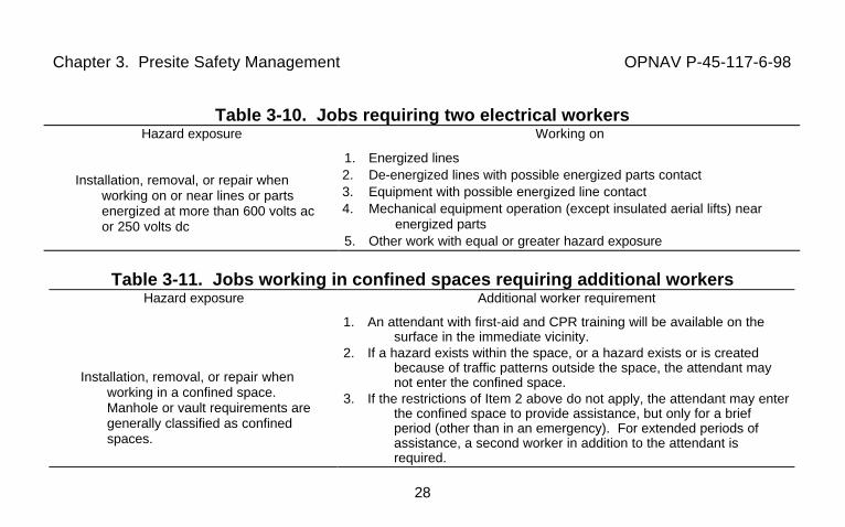
Table 3-10. Jobs requiring two electrical workersHazard exposure Working on
Installation, removal, or repair whenworking on or near lines or partsenergized at more than 600 volts acor 250 volts dc
1. Energized lines2. De-energized lines with possible energized parts contact3. Equipment with possible energized line contact4. Mechanical equipment operation (except insulated aerial lifts) near
energized parts5. Other work with equal or greater hazard exposure
Table 3-11. Jobs working in confined spaces requiring additional workersHazard exposure Additional worker requirement
Installation, removal, or repair whenworking in a confined space.Manhole or vault requirements aregenerally classified as confinedspaces.
1. An attendant with first-aid and CPR training will be available on thesurface in the immediate vicinity.
2. If a hazard exists within the space, or a hazard exists or is createdbecause of traffic patterns outside the space, the attendant maynot enter the confined space.
3. If the restrictions of Item 2 above do not apply, the attendant may enterthe confined space to provide assistance, but only for a briefperiod (other than in an emergency). For extended periods ofassistance, a second worker in addition to the attendant isrequired.
Chapter 3. Presite Safety Management OPNAV P-45-117-6-98
29
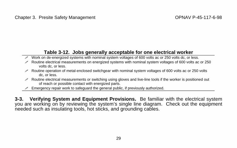
Table 3-12. Jobs generally acceptable for one electrical worker! Work on de-energized systems with nominal system voltages of 600 volts ac or 250 volts dc, or less.! Routine electrical measurements on energized systems with nominal system voltages of 600 volts ac or 250
volts dc, or less.! Routine operation of metal-enclosed switchgear with nominal system voltages of 600 volts ac or 250 volts
dc, or less.! Routine electrical measurements or switching using gloves and live-line tools if the worker is positioned out
of reach or possible contact with energized parts.! Emergency repair work to safeguard the general public, if previously authorized.
3-3. Verifying System and Equipment Provisions. Be familiar with the electrical systemyou are working on by reviewing the system’s single line diagram. Check out the equipmentneeded such as insulating tools, hot sticks, and grounding cables.
Chapter 4. Personal Protective Equipment OPNAV P-45-117-6-98
30
CHAPTER 4. PERSONAL PROTECTIVE EQUIPMENT
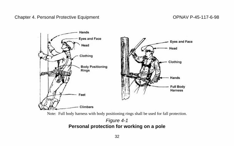
4-1. General Body Protection. Always wear personal protective clothing as required byyour supervisor and as appropriate to the work area, work methods, and site hazards. Wearthese items because it is impossible or impractical to totally eliminate all work site hazardsand they will reduce your chance of injury or illness. OPNAVINST 5100.23, (PersonalProtective Equipment) requires assessment of workplace hazards and provisioning ofappropriate equipment to protect employees from the hazards present. OPNAVINST 5100.23,(Respiratory Protection Program) applies where confined spaces or hazardous gasesmandate respirators. Restrictions on the wearing of jewelry are covered in MIL-HDBK1025/10. Items appropriate for work on a wood pole are shown in Figure 4-1. A summary ofapparel requirements is given in Table 4-1.

Chapter 4. Personal Protective Equipment OPNAV P-45-117-6-98
31
4-2. Additional Worker Protection For Pole/Tree Climbing and for Fall Protection. Poleand tree climbing requires additional personal protective equipment to prevent falls.
a. Climbing Protection. Use climbers only when engaged in work requiring theiruse. Never wear climbers: when working in trees, on ladders, or in aerial lifts; when invehicles; when setting, removing or handling poles; when working on the ground or insidebuildings; or while working on roofs.
(1) Fall Protection. Climbers provide the only fall protection when ascending ordescending poles.
Chapter 4. Personal Protective Equipment OPNAV P-45-117-6-98
32
Note: Full body harness with body positioning rings shall be used for fall protection.
Figure 4-1Personal protection for working on a pole
Chapter 4. Personal Protective Equipment OPNAV P-45-117-6-98
33
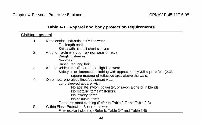
Table 4-1. Apparel and body protection requirements
Clothing - general
1. Nonelectrical industrial activities wearFull length pantsShirts with at least short sleeves
2. Around machinery you may not wear or haveDangling sleevesNecktiesUnsecured long hair
3. Around vehicular traffic or on the flightline wearSafety color fluorescent clothing with approximately 3.5 square feet (0.33
square meters) of reflective area above the waist4. On or near energized lines/equipment wear
Long-sleeved apparel withNo acetate, nylon, polyester, or rayon alone or in blendsNo metallic items (fasteners)No jewelry itemsNo celluloid items
Flame-resistant clothing (Refer to Table 3-7 and Table 3-8)5. Within Flash Protection Boundaries wear
Fire-resistant clothing (Refer to Table 3-7 and Table 3-8)
Chapter 4. Personal Protective Equipment OPNAV P-45-117-6-98
34
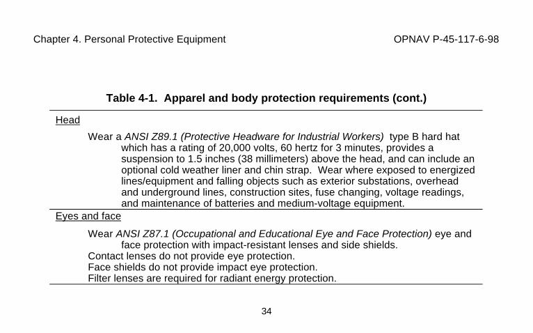
Table 4-1. Apparel and body protection requirements (cont.)
Head
Wear a ANSI Z89.1 (Protective Headware for Industrial Workers) type B hard hatwhich has a rating of 20,000 volts, 60 hertz for 3 minutes, provides asuspension to 1.5 inches (38 millimeters) above the head, and can include anoptional cold weather liner and chin strap. Wear where exposed to energizedlines/equipment and falling objects such as exterior substations, overheadand underground lines, construction sites, fuse changing, voltage readings,and maintenance of batteries and medium-voltage equipment.
Eyes and face
Wear ANSI Z87.1 (Occupational and Educational Eye and Face Protection) eye andface protection with impact-resistant lenses and side shields.
Contact lenses do not provide eye protection.Face shields do not provide impact eye protection.Filter lenses are required for radiant energy protection.
Chapter 4. Personal Protective Equipment OPNAV P-45-117-6-98
35
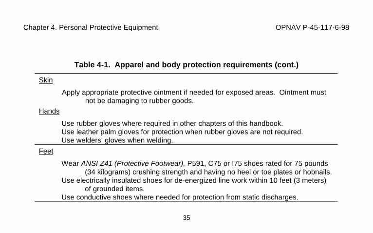
Table 4-1. Apparel and body protection requirements (cont.)
Skin
Apply appropriate protective ointment if needed for exposed areas. Ointment mustnot be damaging to rubber goods.
Hands
Use rubber gloves where required in other chapters of this handbook.Use leather palm gloves for protection when rubber gloves are not required.Use welders’ gloves when welding.
Feet
Wear ANSI Z41 (Protective Footwear), P591, C75 or I75 shoes rated for 75 pounds(34 kilograms) crushing strength and having no heel or toe plates or hobnails.
Use electrically insulated shoes for de-energized line work within 10 feet (3 meters)of grounded items.
Use conductive shoes where needed for protection from static discharges.
Chapter 4. Personal Protective Equipment OPNAV P-45-117-6-98
36
Table 4-1. Apparel and body protection requirements (cont.)
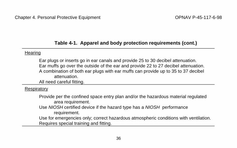
Hearing
Ear plugs or inserts go in ear canals and provide 25 to 30 decibel attenuation.Ear muffs go over the outside of the ear and provide 22 to 27 decibel attenuation.A combination of both ear plugs with ear muffs can provide up to 35 to 37 decibel
attenuation.All need careful fitting.
Respiratory
Provide per the confined space entry plan and/or the hazardous material regulatedarea requirement.
Use NIOSH certified device if the hazard type has a NIOSH performancerequirement.
Use for emergencies only; correct hazardous atmospheric conditions with ventilation.Requires special training and fitting.
Chapter 4. Personal Protective Equipment OPNAV P-45-117-6-98
37
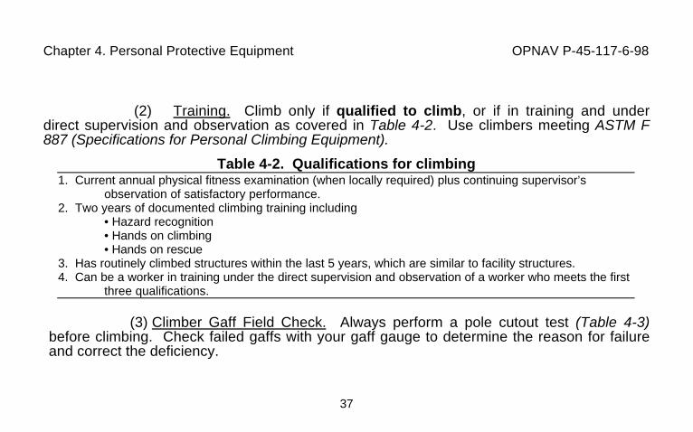
(2) Training. Climb only if qualified to climb, or if in training and underdirect supervision and observation as covered in Table 4-2. Use climbers meeting ASTM F887 (Specifications for Personal Climbing Equipment).
Table 4-2. Qualifications for climbing1. Current annual physical fitness examination (when locally required) plus continuing supervisor’s
observation of satisfactory performance.2. Two years of documented climbing training including
• Hazard recognition• Hands on climbing• Hands on rescue
3. Has routinely climbed structures within the last 5 years, which are similar to facility structures.4. Can be a worker in training under the direct supervision and observation of a worker who meets the first
three qualifications.
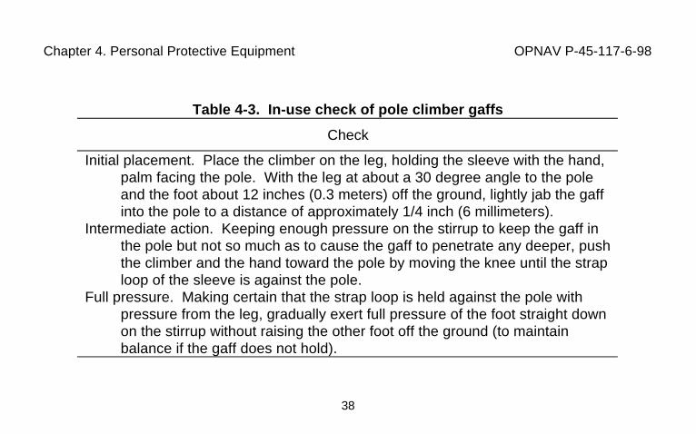
(3) Climber Gaff Field Check. Always perform a pole cutout test (Table 4-3)before climbing. Check failed gaffs with your gaff gauge to determine the reason for failureand correct the deficiency.
Chapter 4. Personal Protective Equipment OPNAV P-45-117-6-98
38
Table 4-3. In-use check of pole climber gaffs
Check
Initial placement. Place the climber on the leg, holding the sleeve with the hand,palm facing the pole. With the leg at about a 30 degree angle to the poleand the foot about 12 inches (0.3 meters) off the ground, lightly jab the gaffinto the pole to a distance of approximately 1/4 inch (6 millimeters).
Intermediate action. Keeping enough pressure on the stirrup to keep the gaff inthe pole but not so much as to cause the gaff to penetrate any deeper, pushthe climber and the hand toward the pole by moving the knee until the straploop of the sleeve is against the pole.
Full pressure. Making certain that the strap loop is held against the pole withpressure from the leg, gradually exert full pressure of the foot straight downon the stirrup without raising the other foot off the ground (to maintainbalance if the gaff does not hold).
Chapter 4. Personal Protective Equipment OPNAV P-45-117-6-98
39
(4) Restrictions on Pole Climbing. Do not climb a pole unless you are sure it can safelyhold your weight. Be sure to inspect for rotted areas, knots, and nails. Check for proper polesupport. Discontinue work during adverse weather conditions such as thunderstorms, rain,high winds, and icy conditions. In bad weather, do not climb poles except for emergencyrestoration work.
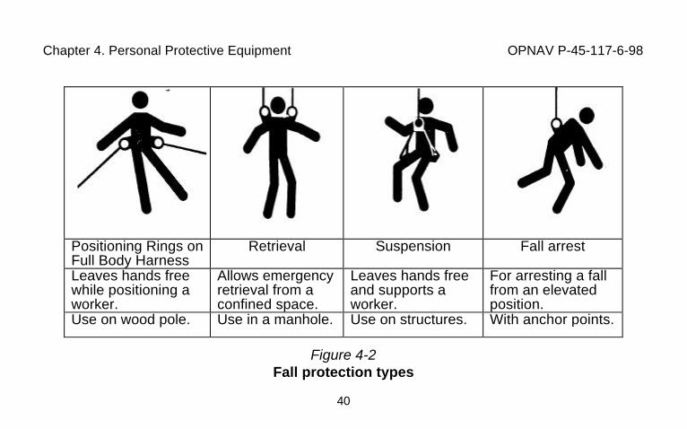
b. Fall Protection. Use of fall protection equipment is required in all instances whileclimbing or changing positions on poles or towers. Four types of fall protection are used tohandle various fall situations as shown in Figure 4-2. Fall arrest equipment is effective only ifadequate anchoring has been identified by a qualified person.
(1) Positioning, Retrieval, and Suspension Fall Protection. Must supportworker’s weight plus any additional load. Does not provide fall arrest. Fall arrest must beadded if it is determined that there is a fall arrest anchor point capable of meeting fall arrestrequirements.
(2) Fall Arrest Protection. Requires an anchor point capable of supporting5,000 pounds (2,250 kilograms) plus a connection device. Protection must provide anadequate free fall distance of 6 feet (1.8 meters) or with a deceleration unit a fall distance of9.5 feet (2.8 meters).
Chapter 4. Personal Protective Equipment OPNAV P-45-117-6-98
40
Positioning Rings onFull Body Harness
Retrieval Suspension Fall arrest
Leaves hands freewhile positioning aworker.
Allows emergencyretrieval from aconfined space.
Leaves hands freeand supports aworker.
For arresting a fallfrom an elevatedposition.
Use on wood pole. Use in a manhole. Use on structures. With anchor points.
Figure 4-2Fall protection types
Chapter 5. Work Area Protective Equipment OPNAV P-45-117-6-98
41
CHAPTER 5. WORK AREA PROTECTIVE EQUIPMENT5-1. Temporary Protective Electrical Insulation. The qualified worker must be protectedfrom electrical energy exposure while either de-energizing (isolating and grounding) the lineor working on a live line. Temporary protective insulation is provided by using the insulatingproperties of rubber goods, plastic guard equipment, and live-line tools. Platforms and aeriallift trucks provide insulated supports for positioning a worker.
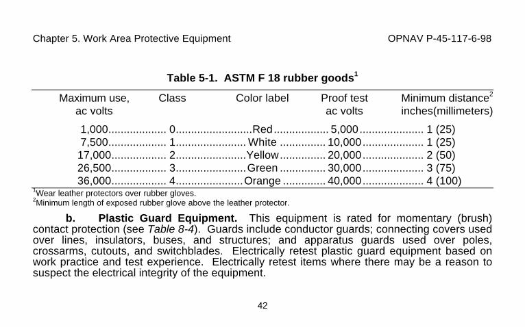
a. Rubber Protective Equipment. Equipment consists of gloves, sleeves,blankets, covers, and line hose. All items must meet or exceed requirements of the applicableASTM F 18 series specification and be suitable for the working voltage level (Table 5-1).Rubber goods should be visually inspected before use.
(1) Air Tests and Visual Inspections. An air test of gloves is also required.Workers should periodically review ASTM F 1236 (Guide for Visual Inspection of ProtectiveRubber Products).
(2) Electrical Retesting. Electrically retest rubber goods issued for servicebased on work practice and test experience intervals. Retesting intervals shall not exceed 6months for rubber gloves and 12 months for rubber sleeves and blankets. Retest any rubbergoods where there may be a reason to suspect the electrical integrity of the equipment.Electrically retest items that have been removed from storage for issue or service, unless theywere electrically tested at the time of placement into storage and storage time does notexceed 12 months.
Chapter 5. Work Area Protective Equipment OPNAV P-45-117-6-98
42
Table 5-1. ASTM F 18 rubber goods1
Maximum use, Class Color label Proof test Minimum distance2
ac volts ac volts inches(millimeters)
1,000................... 0.........................Red.................. 5,000..................... 1 (25)7,500................... 1....................... White ............... 10,000.................... 1 (25)
17,000.................. 2.......................Yellow............... 20,000.................... 2 (50)26,500.................. 3.......................Green ............... 30,000.................... 3 (75)36,000.................. 4......................Orange .............. 40,000.................... 4 (100)
1Wear leather protectors over rubber gloves.2Minimum length of exposed rubber glove above the leather protector.
b. Plastic Guard Equipment. This equipment is rated for momentary (brush)contact protection (see Table 8-4). Guards include conductor guards; connecting covers usedover lines, insulators, buses, and structures; and apparatus guards used over poles,crossarms, cutouts, and switchblades. Electrically retest plastic guard equipment based onwork practice and test experience. Electrically retest items where there may be a reason tosuspect the electrical integrity of the equipment.
Chapter 5. Work Area Protective Equipment OPNAV P-45-117-6-98
43
c. Live-Line Tools. ANSI/IEEE 935 (Guide on Terminology for Tools andEquipment to be Used in Live-Line Working) covers the live-line tools used to hold, move,operate, and test equipment. Tools are only as safe as their continued care and inspectionmake them. Try to always use a fiberglass tool as it is impervious to oil-borne materials andsolvents, is stronger, and is a better insulator than wood. Live-line tools will be wiped cleanand visually inspected before use each day. Do not use tools in rain or heavy fog, except inan emergency where directed by your foreman/lead electrician. In any case, never use toolswhen weather conditions allow formation of rivulets of water along the tool. Hang tools onhand lines or approved tool hangers, never on conductors or ground (bond) wires. Seeparagraph 8-3 for further information.
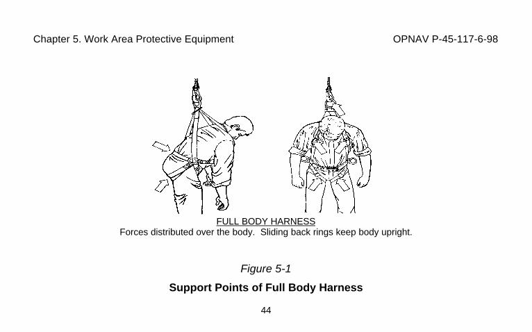
d. Equipment for Positioning a Worker. Body harnesses, platforms, and aeriallift buckets are used to position workers performing elevated electrical maintenance. SeeFigure 5-1 for the advantages of body harnesses. Always use fiberglass ladders andplatforms (See Table 5-2, Ladder inspections, Table 5-3, Proper care and storage of ladders,and Table 5-4, Proper setup and use of ladders). Review the safety rules given in themanufactures’ operating manual when using aerial lifts (insulated buckets), vehicle-mountedelevating and rotating work platforms, manually-propelled mobile work platforms, andscaffolds (towers). Body harnesses must be worn with a lanyard attached to the boom orbucket. Climbers will not be worn by workers when in an aerial lift bucket. Only oneenergized conductor may be worked at a time regardless of the number of workers on the poleand/or in the bucket.
Chapter 5. Work Area Protective Equipment OPNAV P-45-117-6-98
44
FULL BODY HARNESSForces distributed over the body. Sliding back rings keep body upright.
Figure 5-1
Support Points of Full Body Harness
Chapter 5. Work Area Protective Equipment OPNAV P-45-117-6-98
45
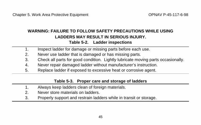
WARNING: FAILURE TO FOLLOW SAFETY PRECAUTIONS WHILE USINGLADDERS MAY RESULT IN SERIOUS INJURY.
Table 5-2. Ladder inspections
1. Inspect ladder for damage or missing parts before each use.2. Never use ladder that is damaged or has missing parts.3. Check all parts for good condition. Lightly lubricate moving parts occasionally.4. Never repair damaged ladder without manufacturer’s instruction.5. Replace ladder if exposed to excessive heat or corrosive agent.
Table 5-3. Proper care and storage of ladders1. Always keep ladders clean of foreign materials.2. Never store materials on ladders.3. Properly support and restrain ladders while in transit or storage.
Chapter 5. Work Area Protective Equipment OPNAV P-45-117-6-98
46
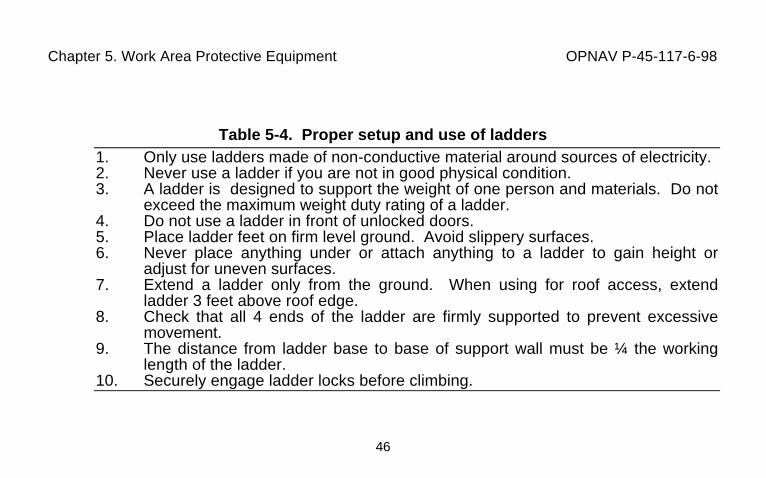
Table 5-4. Proper setup and use of ladders1. Only use ladders made of non-conductive material around sources of electricity.2. Never use a ladder if you are not in good physical condition.3. A ladder is designed to support the weight of one person and materials. Do not
exceed the maximum weight duty rating of a ladder.4. Do not use a ladder in front of unlocked doors.5. Place ladder feet on firm level ground. Avoid slippery surfaces.6. Never place anything under or attach anything to a ladder to gain height or
adjust for uneven surfaces.7. Extend a ladder only from the ground. When using for roof access, extend
ladder 3 feet above roof edge.8. Check that all 4 ends of the ladder are firmly supported to prevent excessive
movement.9. The distance from ladder base to base of support wall must be ¼ the working
length of the ladder.10. Securely engage ladder locks before climbing.
Chapter 5. Work Area Protective Equipment OPNAV P-45-117-6-98
47
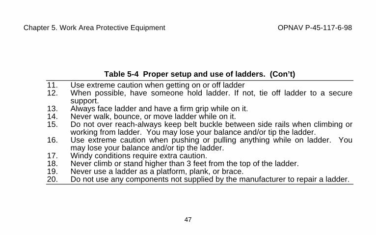
Table 5-4 Proper setup and use of ladders. (Con’t)11. Use extreme caution when getting on or off ladder12. When possible, have someone hold ladder. If not, tie off ladder to a secure
support.13. Always face ladder and have a firm grip while on it.14. Never walk, bounce, or move ladder while on it.15. Do not over reach-always keep belt buckle between side rails when climbing or
working from ladder. You may lose your balance and/or tip the ladder.16. Use extreme caution when pushing or pulling anything while on ladder. You
may lose your balance and/or tip the ladder.17. Windy conditions require extra caution.18. Never climb or stand higher than 3 feet from the top of the ladder.19. Never use a ladder as a platform, plank, or brace.20. Do not use any components not supplied by the manufacturer to repair a ladder.
Chapter 5. Work Area Protective Equipment OPNAV P-45-117-6-98
48
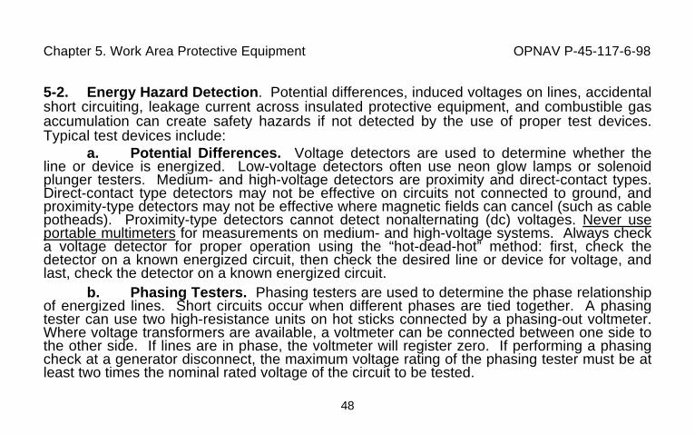
5-2. Energy Hazard Detection. Potential differences, induced voltages on lines, accidentalshort circuiting, leakage current across insulated protective equipment, and combustible gasaccumulation can create safety hazards if not detected by the use of proper test devices.Typical test devices include:
a. Potential Differences. Voltage detectors are used to determine whether theline or device is energized. Low-voltage detectors often use neon glow lamps or solenoidplunger testers. Medium- and high-voltage detectors are proximity and direct-contact types.Direct-contact type detectors may not be effective on circuits not connected to ground, andproximity-type detectors may not be effective where magnetic fields can cancel (such as cablepotheads). Proximity-type detectors cannot detect nonalternating (dc) voltages. Never useportable multimeters for measurements on medium- and high-voltage systems. Always checka voltage detector for proper operation using the “hot-dead-hot” method: first, check thedetector on a known energized circuit, then check the desired line or device for voltage, andlast, check the detector on a known energized circuit.
b. Phasing Testers. Phasing testers are used to determine the phase relationshipof energized lines. Short circuits occur when different phases are tied together. A phasingtester can use two high-resistance units on hot sticks connected by a phasing-out voltmeter.Where voltage transformers are available, a voltmeter can be connected between one side tothe other side. If lines are in phase, the voltmeter will register zero. If performing a phasingcheck at a generator disconnect, the maximum voltage rating of the phasing tester must be atleast two times the nominal rated voltage of the circuit to be tested.
Chapter 5. Work Area Protective Equipment OPNAV P-45-117-6-98
49
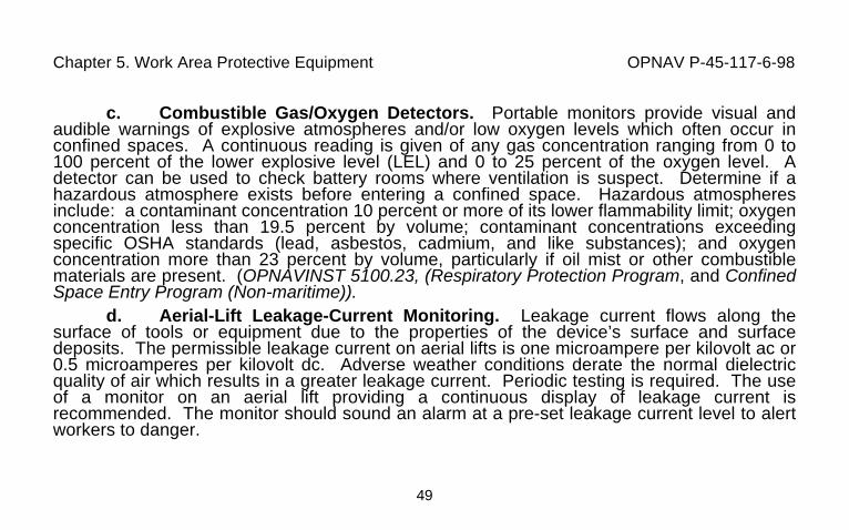
c. Combustible Gas/Oxygen Detectors. Portable monitors provide visual andaudible warnings of explosive atmospheres and/or low oxygen levels which often occur inconfined spaces. A continuous reading is given of any gas concentration ranging from 0 to100 percent of the lower explosive level (LEL) and 0 to 25 percent of the oxygen level. Adetector can be used to check battery rooms where ventilation is suspect. Determine if ahazardous atmosphere exists before entering a confined space. Hazardous atmospheresinclude: a contaminant concentration 10 percent or more of its lower flammability limit; oxygenconcentration less than 19.5 percent by volume; contaminant concentrations exceedingspecific OSHA standards (lead, asbestos, cadmium, and like substances); and oxygenconcentration more than 23 percent by volume, particularly if oil mist or other combustiblematerials are present. (OPNAVINST 5100.23, (Respiratory Protection Program, and ConfinedSpace Entry Program (Non-maritime)).
d. Aerial-Lift Leakage-Current Monitoring. Leakage current flows along thesurface of tools or equipment due to the properties of the device’s surface and surfacedeposits. The permissible leakage current on aerial lifts is one microampere per kilovolt ac or0.5 microamperes per kilovolt dc. Adverse weather conditions derate the normal dielectricquality of air which results in a greater leakage current. Periodic testing is required. The useof a monitor on an aerial lift providing a continuous display of leakage current isrecommended. The monitor should sound an alarm at a pre-set leakage current level to alertworkers to danger.
Chapter 6. De-energized Line Clearance OPNAV P-45-117-6-98
50
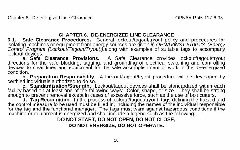
CHAPTER 6. DE-ENERGIZED LINE CLEARANCE6-1. Safe Clearance Procedures. General lockout/tagout/tryout policy and procedures forisolating machines or equipment from energy sources are given in OPNAVINST 5100.23, (EnergyControl Program (Lockout/Tagout/Tryout)),along with examples of suitable tags to accompanylockout devices.
a. Safe Clearance Provisions. A Safe Clearance provides lockout/tagout/tryoutdirections for the safe blocking, tagging, and grounding of electrical switching and controllingdevices to clear lines and equipment for the safe accomplishment of work in the de-energizedcondition.
b. Preparation Responsibility. A lockout/tagout/tryout procedure will be developed bycertified individuals authorized to do so.
c. Standardization/Strength. Lockout/tagout devices shall be standardized within eachfacility based on at least one of the following ways: Color, shape, or size. They shall be strongenough to prevent removal except in cases of excessive force, such as the use of bolt cutters.
d. Tag Recognition. In the process of lockout/tagout/tryout, tags defining the hazard andthe control measure to be used must be filled in, including the names of the individual responsiblefor the tag and the functional manager. The tags must warn against hazardous conditions if themachine or equipment is energized and shall include a legend such as the following:
DO NOT START, DO NOT OPEN, DO NOT CLOSE,DO NOT ENERGIZE, DO NOT OPERATE.
Chapter 6. De-energized Line Clearance OPNAV P-45-117-6-98
51
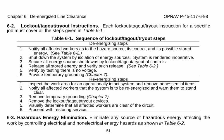
6-2. Lockout/tagout/tryout Instructions. Each lockout/tagout/tryout instruction for a specificjob must cover all the steps given in Table 6-1.
Table 6-1. Sequence of lockout/tagout/tryout stepsDe-energizing steps
1. Notify all affected workers as to the hazard source, its control, and its possible storedenergy. (See Table 6-2.)
2. Shut down the system by isolation of energy sources. System is rendered inoperative.3. Secure all energy source shutdowns by lockout/tagout/tryout of controls.4. Release all stored energy and verify such release. (See Table 6-2.)5. Verify by testing there is no voltage.6. Provide temporary grounding (Chapter 7).
Re-energizing steps1. Inspect the work area for an operationally intact system and remove nonessential items.2. Notify all affected workers that the system is to be re-energized and warn them to stand
clear.3. Remove temporary grounding (Chapter 7).4. Remove the lockout/tagout/tryout devices.5. Visually determine that all affected workers are clear of the circuit.6. Proceed with restoring service.
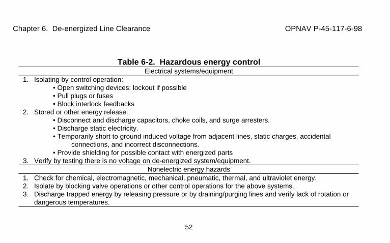
6-3. Hazardous Energy Elimination. Eliminate any source of hazardous energy affecting thework by controlling electrical and nonelectrical energy hazards as shown in Table 6-2.
Chapter 6. De-energized Line Clearance OPNAV P-45-117-6-98
52
Table 6-2. Hazardous energy controlElectrical systems/equipment
1. Isolating by control operation:• Open switching devices; lockout if possible• Pull plugs or fuses• Block interlock feedbacks
2. Stored or other energy release:• Disconnect and discharge capacitors, choke coils, and surge arresters.• Discharge static electricity.• Temporarily short to ground induced voltage from adjacent lines, static charges, accidental
connections, and incorrect disconnections.• Provide shielding for possible contact with energized parts
3. Verify by testing there is no voltage on de-energized system/equipment.Nonelectric energy hazards
1. Check for chemical, electromagnetic, mechanical, pneumatic, thermal, and ultraviolet energy.2. Isolate by blocking valve operations or other control operations for the above systems.3. Discharge trapped energy by releasing pressure or by draining/purging lines and verify lack of rotation or
dangerous temperatures.
Chapter 7. De-energized Line Grounding OPNAV P-45-117-6-98
53
CHAPTER 7. DE-ENERGIZED LINE GROUNDING7-1. Grounding Provision. Grounding is used to limit dangerous potentials. Permanentgrounding is provided as a part of any electrical system to meet safety and designrequirements. A ground system consists of a grounding connection, a grounding conductor, agrounding electrode, and the earth (soil) that surrounds the electrode or some conductivebody which serves instead of the earth (a ship hull/aircraft frame). A jumper connectsconductors so that continuity is maintained. Bonding is the joining of metallic parts to form aconductive path. Temporary grounds are used so that work may be safely done on parts ofthe system that are temporarily isolated and cleared (de-energized).
Chapter 7. De-energized Line Grounding OPNAV P-45-117-6-98
54
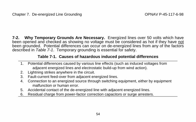
7-2. Why Temporary Grounds Are Necessary. Energized lines over 50 volts which havebeen opened and checked as showing no voltage must be considered as hot if they have notbeen grounded. Potential differences can occur on de-energized lines from any of the factorsdescribed in Table 7-1. Temporary grounding is essential for safety.
Table 7-1. Causes of hazardous induced potential differences
1. Potential differences caused by various line effects (such as induced voltages fromadjacent energized lines and electrostatic build-up from wind action).
2. Lightning strikes anywhere in the circuit.3. Fault-current feed-over from adjacent energized lines.4. Connection to an energized source through switching equipment, either by equipment
malfunction or human error.5. Accidental contact of the de-energized line with adjacent energized lines.6. Residual charge from power-factor correction capacitors or surge arresters.
Chapter 7. De-energized Line Grounding OPNAV P-45-117-6-98
55
7-3. Equipotential (Single Point) Grounding. Whenever possible install temporarygrounding to provide an equipotential zone at the work site. An equipotential zone provides azero ground potential gradient across a worker’s body, thus preventing a harmful electricalcurrent through the worker. Figure 1-1 shows the voltage gradient around a groundedenergized object when a ground fault occurs. Figure 1-2 shows the current path across theworker’s body which flows when there is a potential difference between two different points oran individual’s contact with the ground or a grounded structure. Table 6-1 indicates wheregrounds are provided in the sequence of de-energized lockout/tagout/tryout steps.7-4. Placement of Grounds. Grounds will be installed as close as possible to the work.Temporary grounding connection/removal procedures will be in accordance with Table 7-2.Never approach closer than working distances given in Table 3-7 and Table 3-8 until after theline/equipment has been isolated, de-energized, tested, and properly grounded. Afterwards,avoid coming closer than 10 feet (3 meters) to minimize the hazard from step and touchpotentials. This minimizes step and touch potential differences. Such potential differencesoccur from items such as down guys, ground rods, maintenance vehicles, and structure legsor ground wires during the period in which they are bonded to temporary grounds. When it isabsolutely necessary to work on or near these features, workers should use bondedconductive or insulated platforms, or approved insulated shoes to minimize the hazard fromstep and touch potentials. Bond separately grounded systems together if they can besimultaneously contacted.
Chapter 7. De-energized Line Grounding OPNAV P-45-117-6-98
56
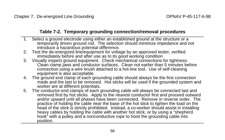
Table 7-2. Temporary grounding connection/removal procedures
1. Select a ground electrode using either an established ground at the structure or atemporarily driven ground rod. The selection should minimize impedance and notintroduce a hazardous potential difference.
2. Test the de-energized line/equipment for voltage by an approved tester, verifiedimmediately before and after use as to its good working condition
3. Visually inspect ground equipment. Check mechanical connections for tightness.Clean clamp jaws and conductor surfaces. Clean not earlier than 5 minutes beforeconnection using a wire brush attached to a hot-line tool. Use of self-cleaningequipment is also acceptable.
4. The ground end clamp of each grounding cable should always be the first connectionmade and the last to be removed. Hot sticks will be used if the grounded system andworker are at different potentials.
5. The conductor-end clamps of each grounding cable will always be connected last andremoved first by hot sticks. Apply to the nearest conductor first and proceed outwardand/or upward until all phases have been connected. Remove in reverse order. Thepractice of holding the cable near the base of the hot stick to lighten the load on thehead of the stick is strictly prohibited. Instead, a co-worker should assist in installingheavy cables by holding the cable with another hot stick, or by using a “shepherdhook” with a pulley and a nonconductive rope to hoist the grounding cable intoposition.
Chapter 7. De-energized Line Grounding OPNAV P-45-117-6-98
57
7-5. Temporary Grounding System Components. Use system application (overhead,underground, substation) sets with ASTM F 855 (Temporary Grounding Systems to be Usedon De-Energized Electric Power Lines and Equipment) grounding jumpers (clamps, ferrules,and clear 600-volt jacketed elastomer flexible cable) to the maximum possible extent.
a. Clamps. Use the alloy (copper or aluminum) matching the conductor or deviceto which it is attached and meeting or exceeding the current-carrying capacity of theassociated cable. Use smooth jaw clamps on buses to avoid surface marring. Use serratedclamp jaws to bite through corrosion products for attachment to conductors or metal products.Self-cleaning jaws are recommended for use on aluminum. Never use hot-line clamps forgrounding.
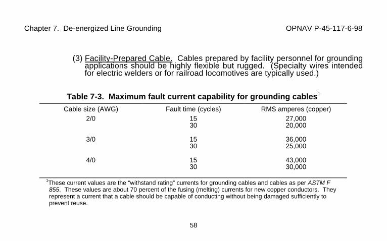
b. Cable. Cables will be preferably ASTM F 855, Type I of a minimum 2/0 AWGcopper selected to meet the fault current necessary as given for 15-cycle substation duty and30-cycle line use. See Table 7-3.
(1) Derating. Derate the fault current by 10 percent when using multipleground cables (which must all be of the same size and length).
(2) Handling. Handle cables to avoid conductor strand breakage from sharpbends or excessive continuous flexing. Avoid excessive cable length because an increasedresistance can elevate potential differences and twisting or coiling reduces their current-carrying capacity. Avoid very low temperatures; the clear jacket which allows checking forstrand breakage will stiffen at low temperatures and split or shatter.
Chapter 7. De-energized Line Grounding OPNAV P-45-117-6-98
58
(3) Facility-Prepared Cable. Cables prepared by facility personnel for groundingapplications should be highly flexible but rugged. (Specialty wires intendedfor electric welders or for railroad locomotives are typically used.)
Table 7-3. Maximum fault current capability for grounding cables1
Cable size (AWG) Fault time (cycles) RMS amperes (copper)2/0 15
3027,00020,000
3/0 1530
36,00025,000
4/0 1530
43,00030,000
1These current values are the “withstand rating” currents for grounding cables and cables as per ASTM F855. These values are about 70 percent of the fusing (melting) currents for new copper conductors. Theyrepresent a current that a cable should be capable of conducting without being damaged sufficiently toprevent reuse.
Chapter 7. De-energized Line Grounding OPNAV P-45-117-6-98
59
c. Ferrules. Use ASTM F 855, Type IV (threaded stud copper base compressiontype) when installed on grounding cables by facility personnel. Ferrules should have the fillercompound vent hole at the bottom of the cable so that employees can visually check that thecable is fully inserted into the ferrule. Heat shrink or springs should be installed over a portionof the ferrule to minimize strand breakage caused by bending. In all cases, themanufacturer’s recommendations should be followed. Do not use aluminum alloy ferrules asthey will not provide a lasting snug fit. Check for tightness periodically.
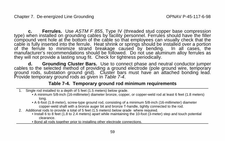
d. Grounding Cluster Bars. Use to connect phase and neutral conductor jumpercables to the selected method of providing a ground electrode (pole ground wire, temporaryground rods, substation ground grid). Cluster bars must have an attached bonding lead.Provide temporary ground rods as given in Table 7-4.
Table 7-4. Temporary ground rod minimum requirements1. Single rod installed to a depth of 5 feet (1.5 meters) below grade.
• A minimum 5/8-inch (16-millimeter) diameter bronze, copper, or copper-weld rod at least 6 feet (1.8 meters)long.
• A 6-foot (1.8-meter), screw-type ground rod, consisting of a minimum 5/8-inch (16-millimeter) diametercopper-weld shaft with a bronze auger bit and bronze T-handle, tightly connected to the rod.
2. Additional rods to provide a total of 5 feet (1.5 meters) below grade where required.• Install 6 to 8 feet (1.8 to 2.4 meters) apart while maintaining the 10-foot (3-meter) step and touch potential
clearance.• Bond all rods together prior to installing other electrode connections.
Chapter 7. De-energized Line Grounding OPNAV P-45-117-6-98
60
7-6. Temporary Grounding of Aerial Lines. Ground by installing an overhead distributiongrounding set. The grounding set provides a parallel low-level (milliohm) resistance pathwhich limits the current flow through the worker to a very low (safe) value (milliamperes) thuslimiting the potential across the worker to a safe value. If the ground resistance were in serieswith the worker life-endangering currents could flow through the worker under fault conditions.Avoid any ground connection which could provide violent whipping from wind action. Double-point grounds are sometimes utilized but single-point (equipotential) grounding is thepreferred method. If double-point grounding is necessary, install the temporary grounds atleast one span away from the work site because the grounding cables may violently moveduring a fault condition.
Chapter 7. De-energized Line Grounding OPNAV P-45-117-6-98
61
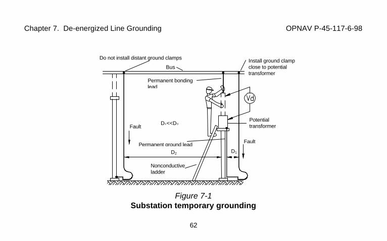
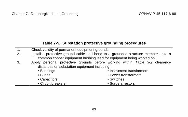
7-7. Temporary Grounding of Substation Current-Carrying Equipment Components.Ground de-energized current-carrying components of substation equipment beforeapproaching them within working clearance distances given in Tables 3-7 and Tables 3-8.Grounds should be placed as close to the equipment as practical (see distance D1 on Figure7-1) to minimize the inductive voltage loop (see distance D2 on Figure 7-1) formed by theground cable and the worker. See Tables 7-5 and 7-6. Special precautions are neededduring oil handling (Table7-7).
Chapter 7. De-energized Line Grounding OPNAV P-45-117-6-98
62
Figure 7-1Substation temporary grounding
Permanent bondinglead
Bus
Do not install distant ground clamps Install ground clampclose to potentialtransformer
Potentialtransformer
Fault
D1D2
Nonconductiveladder
Permanent ground lead
FaultD1<<D2
Chapter 7. De-energized Line Grounding OPNAV P-45-117-6-98
63
Table 7-5. Substation protective grounding procedures
1. Check validity of permanent equipment grounds.2. Install a protective ground cable and bond to a grounded structure member or to a
common copper equipment bushing lead for equipment being worked on.3. Apply personal protective grounds before working within Table 3-2 clearance
distances on substation equipment including:• Bushings • Instrument transformers• Buses • Power transformers• Capacitors • Switches• Circuit breakers • Surge arrestors
Chapter 7. De-energized Line Grounding OPNAV P-45-117-6-98
64
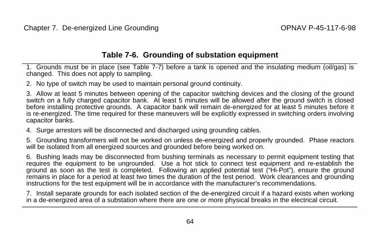
Table 7-6. Grounding of substation equipment1. Grounds must be in place (see Table 7-7) before a tank is opened and the insulating medium (oil/gas) ischanged. This does not apply to sampling.
2. No type of switch may be used to maintain personal ground continuity.
3. Allow at least 5 minutes between opening of the capacitor switching devices and the closing of the groundswitch on a fully charged capacitor bank. At least 5 minutes will be allowed after the ground switch is closedbefore installing protective grounds. A capacitor bank will remain de-energized for at least 5 minutes before itis re-energized. The time required for these maneuvers will be explicitly expressed in switching orders involvingcapacitor banks.
4. Surge arrestors will be disconnected and discharged using grounding cables.
5. Grounding transformers will not be worked on unless de-energized and properly grounded. Phase reactorswill be isolated from all energized sources and grounded before being worked on.
6. Bushing leads may be disconnected from bushing terminals as necessary to permit equipment testing thatrequires the equipment to be ungrounded. Use a hot stick to connect test equipment and re-establish theground as soon as the test is completed. Following an applied potential test (“Hi-Pot”), ensure the groundremains in place for a period at least two times the duration of the test period. Work clearances and groundinginstructions for the test equipment will be in accordance with the manufacturer’s recommendations.
7. Install separate grounds for each isolated section of the de-energized circuit if a hazard exists when workingin a de-energized area of a substation where there are one or more physical breaks in the electrical circuit.
Chapter 7. De-energized Line Grounding OPNAV P-45-117-6-98
65
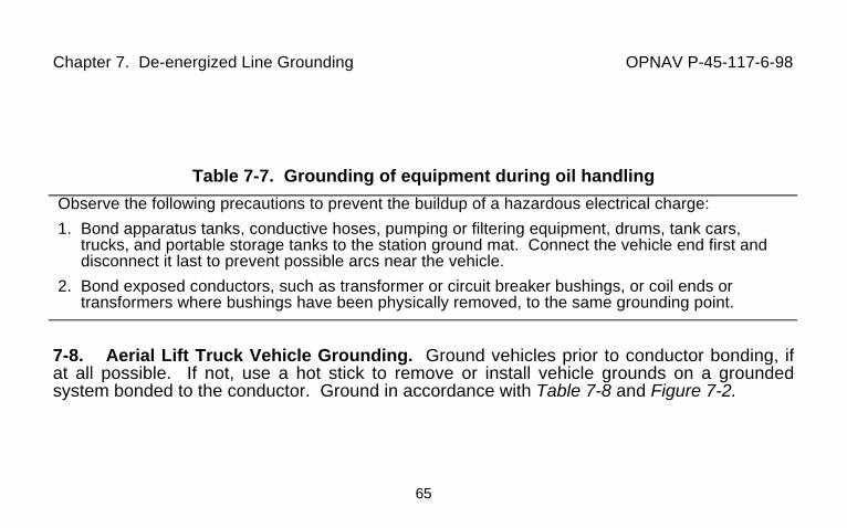
Table 7-7. Grounding of equipment during oil handling
Observe the following precautions to prevent the buildup of a hazardous electrical charge:
1. Bond apparatus tanks, conductive hoses, pumping or filtering equipment, drums, tank cars,trucks, and portable storage tanks to the station ground mat. Connect the vehicle end first anddisconnect it last to prevent possible arcs near the vehicle.
2. Bond exposed conductors, such as transformer or circuit breaker bushings, or coil ends ortransformers where bushings have been physically removed, to the same grounding point.
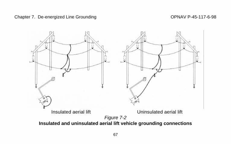
7-8. Aerial Lift Truck Vehicle Grounding. Ground vehicles prior to conductor bonding, ifat all possible. If not, use a hot stick to remove or install vehicle grounds on a groundedsystem bonded to the conductor. Ground in accordance with Table 7-8 and Figure 7-2.
Chapter 7. De-energized Line Grounding OPNAV P-45-117-6-98
66
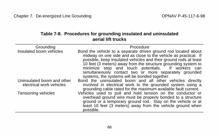
Table 7-8. Procedures for grounding insulated and uninsulatedaerial lift trucks
Grounding ProcedureInsulated boom vehicles Bond the vehicle to a separate driven ground rod located about
midway on one side and as close to the vehicle as practical. Ifpossible, keep insulated vehicles and their ground rods at least10 feet (3 meters) away from the structure grounding system tominimize step and touch potentials. If workers cansimultaneously contact two or more separately groundedsystems, the systems will be bonded together.
Uninsulated boom and otherelectrical work vehicles
Bond the uninsulated boom and all other vehicles directlyinvolved in electrical work to the grounded system using agrounding cable rated for the maximum available fault current.
Tensioning vehicles Vehicles used to pull and hold tension on the conductor oroverhead ground wire must be properly bonded to a structureground or a temporary ground rod. Stay on the vehicle or atleast 10 feet (3 meters) away from the vehicle ground whenpossible.
Chapter 7. De-energized Line Grounding OPNAV P-45-117-6-98
67
Insulated aerial lift Uninsulated aerial liftFigure 7-2
Insulated and uninsulated aerial lift vehicle grounding connections
Chapter 7. De-energized Line Grounding OPNAV P-45-117-6-98
68
7-9. Temporary Grounding of Underground Lines. Ground all possible sources of power(including transformer backfeed). Omission of grounds will be permitted only if theirapplication decreases the work hazard. Install protective grounds at equipment terminationsor ground by spiking cable (using an approved tool) prior to work on the cable. Use approvedground sets of the type shown on Figure 7-3.
7-10. Opening or Splicing De-Energized Conductors. Conductors may be spliced atground level, from aerial lift equipment utilizing ground mats (uninsulated aerial lifts), or frominsulating platforms (insulated aerial lifts). Grounding for conductive or insulating platforms isshown on Figure 7-4. Install all grounding jumpers with hot sticks. Steps in providing safegrounds are given in Table 7-2. Remove in reverse order as installed. Ground any mobileequipment. Stay 10 feet (3 meters) away from grounded items and step onto equipment orplatforms as quickly as possible to minimize any adverse step and touch potentials.
7-11. Grounding for Stringing and Removing Lines. Locate grounds to meet requirementsof Table 7-9 and Figure 7-5. After conductor pulling, locate grounds in accordance with Table7-10.
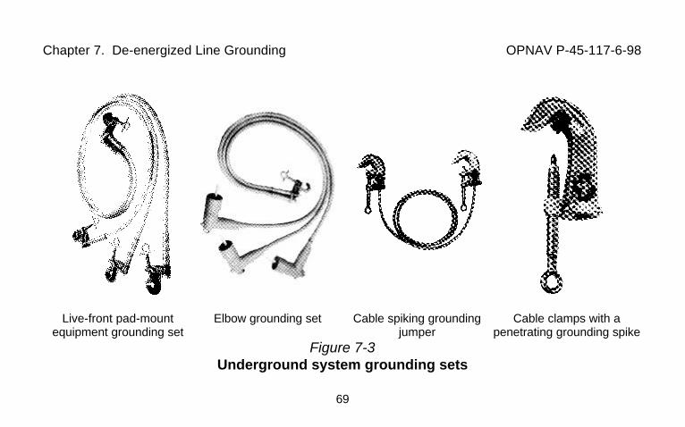
Chapter 7. De-energized Line Grounding OPNAV P-45-117-6-98
69
Live-front pad-mountequipment grounding set
Elbow grounding set Cable spiking groundingjumper
Cable clamps with apenetrating grounding spike
Figure 7-3Underground system grounding sets
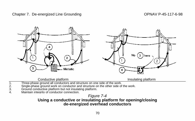
Chapter 7. De-energized Line Grounding OPNAV P-45-117-6-98
70
Conductive platform Insulating platform
1. Three-phase ground all conductors and structure on one side of the work.2. Single-phase ground work on conductor and structure on the other side of the work.3. Ground conductive platform but not insulating platform.4. Maintain integrity of conductor connection.
Figure 7-4Using a conductive or insulating platform for opening/closing
de-energized overhead conductors
2
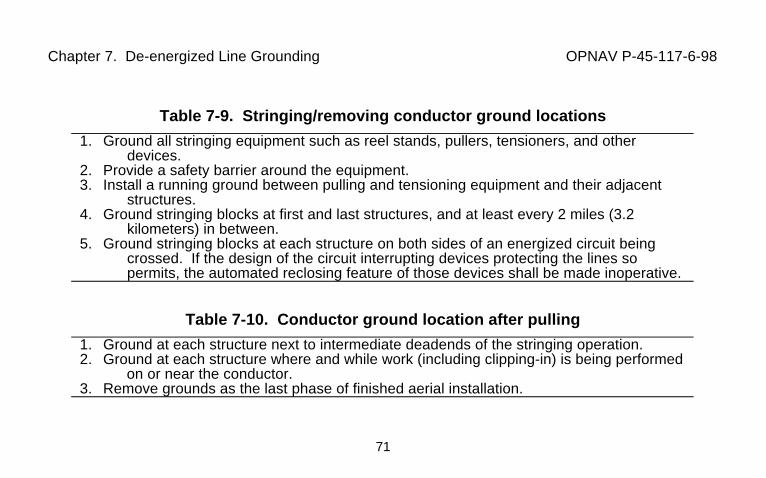
Chapter 7. De-energized Line Grounding OPNAV P-45-117-6-98
71
Table 7-9. Stringing/removing conductor ground locations
1. Ground all stringing equipment such as reel stands, pullers, tensioners, and otherdevices.
2. Provide a safety barrier around the equipment.3. Install a running ground between pulling and tensioning equipment and their adjacent
structures.4. Ground stringing blocks at first and last structures, and at least every 2 miles (3.2
kilometers) in between.5. Ground stringing blocks at each structure on both sides of an energized circuit being
crossed. If the design of the circuit interrupting devices protecting the lines sopermits, the automated reclosing feature of those devices shall be made inoperative.
Table 7-10. Conductor ground location after pulling
1. Ground at each structure next to intermediate deadends of the stringing operation.2. Ground at each structure where and while work (including clipping-in) is being performed
on or near the conductor.3. Remove grounds as the last phase of finished aerial installation.
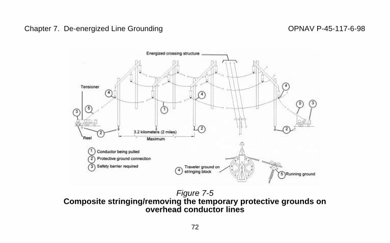
Chapter 7. De-energized Line Grounding OPNAV P-45-117-6-98
72
Figure 7-5Composite stringing/removing the temporary protective grounds on
overhead conductor lines
Chapter 8. Energized Line Work OPNAV P-45-117-6-98
73
CHAPTER 8. ENERGIZED LINE WORK8-1. Normal Work Methods. Lines will be worked de-energized, except where energizedline maintenance has been approved by the Commanding Officer and considered necessaryto support a critical mission, prevent human injury, or protect property. Observe approvedwork methods, equipment prework procedures, and general job-in-progress procedures. Nowork may be performed during adverse weather conditions (ice storms, high winds, electricstorms) unless there is an emergency and the work has been approved. See Tables 3-8, 3-9,and 3-10 for number of qualified workers. All energized line work will require written, jobspecific procedures that are approved by the Public Works Officer (PWO).
8-2. Permitted Energized Line Work Methods. Only the approved methods given in Table8-1 can be used by facility workers in performing energized line maintenance.
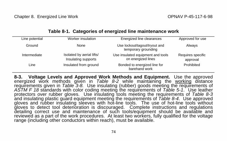
Chapter 8. Energized Line Work OPNAV P-45-117-6-98
74
Table 8-1. Categories of energized line maintenance workLine potential Worker insulation Energized line clearances Approved for use
Ground None Use lockout/tagout/tryout andtemporary grounding
Always
Intermediate Isolated by aerial lifts/Insulating supports
Use insulated equipment and toolson energized lines
Requires specificapproval
Line Insulated from ground Bonded to energized line forbarehand work
Prohibited
8-3. Voltage Levels and Approved Work Methods and Equipment. Use the approvedenergized work methods given in Table 8-2 while maintaining the working distancerequirements given in Table 3-8. Use insulating (rubber) goods meeting the requirements ofASTM F 18 standards with color coding meeting the requirements of Table 5-1. Use leatherprotectors over rubber gloves. Use insulating tools meeting the requirements of Table 8-3and insulating plastic guard equipment meeting the requirements of Table 8-4. Use approvedgloves and rubber insulating sleeves with hot-line tools. The use of hot-line tools withoutgloves to detect tool deterioration is discouraged. Complete instructions and regulationsdetailing correct use and maintenance of such tools/equipment should be available andreviewed as a part of the work procedures. At least two workers, fully qualified for the voltagerange (including other conductors within reach), must be available.
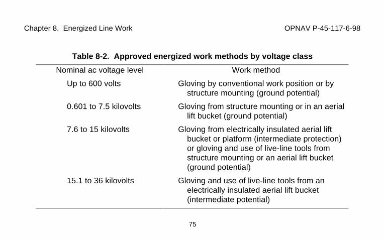
Chapter 8. Energized Line Work OPNAV P-45-117-6-98
75
Table 8-2. Approved energized work methods by voltage class
Nominal ac voltage level Work method
Up to 600 volts Gloving by conventional work position or bystructure mounting (ground potential)
0.601 to 7.5 kilovolts Gloving from structure mounting or in an aeriallift bucket (ground potential)
7.6 to 15 kilovolts Gloving from electrically insulated aerial liftbucket or platform (intermediate protection)or gloving and use of live-line tools fromstructure mounting or an aerial lift bucket(ground potential)
15.1 to 36 kilovolts Gloving and use of live-line tools from anelectrically insulated aerial lift bucket(intermediate potential)

Chapter 8. Energized Line Work OPNAV P-45-117-6-98
76
Table 8-3. Insulating tools for electrical workers
StandardsASTM F711, Specification for Fiberglass Reinforced Plastic (FRP) Rod and Tube Used in
Live-Line Tools.IEEE Std 978, Guide for In-Service Maintenance and Electrical Testing of Live-Line Tools.
Minimum test valuesTool material OSHA acceptance1 IEEE in-service2 Use
Fiberglass reinforcedplastic (FRP)
100 kV/foot (0.3 meters) 75 kV/foot (0.3 meters) Preferred3
Wood 75 kV/foot (0.3 meters) 50 kV/foot (0.3 meters) Phase-out41Test values manufacturers must certify for acceptance by buyer.2Test values required after acceptance and tested after use in the field. Electrically test at intervals of not more than 6
months for tools in frequent use. Electrically test at intervals of not more than one year for tools stored for longperiods of time.
3All new tools will be FRP.4Replace wood hot line tools with FRP tools.
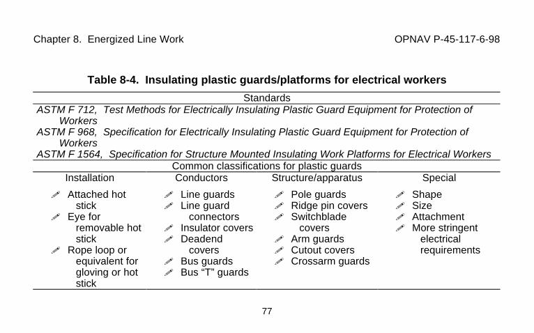
Chapter 8. Energized Line Work OPNAV P-45-117-6-98
77
Table 8-4. Insulating plastic guards/platforms for electrical workers
StandardsASTM F 712, Test Methods for Electrically Insulating Plastic Guard Equipment for Protection of
WorkersASTM F 968, Specification for Electrically Insulating Plastic Guard Equipment for Protection of
WorkersASTM F 1564, Specification for Structure Mounted Insulating Work Platforms for Electrical Workers
Common classifications for plastic guardsInstallation Conductors Structure/apparatus Special
! Attached hotstick
! Eye forremovable hotstick
! Rope loop orequivalent forgloving or hotstick
! Line guards! Line guard
connectors! Insulator covers! Deadend
covers! Bus guards! Bus “T” guards
! Pole guards! Ridge pin covers! Switchblade
covers! Arm guards! Cutout covers! Crossarm guards
! Shape! Size! Attachment! More stringent
electricalrequirements
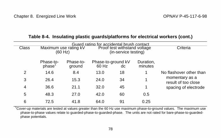
Chapter 8. Energized Line Work OPNAV P-45-117-6-98
78
Table 8-4. Insulating plastic guards/platforms for electrical workers (cont.)
Guard rating for accidental brush contactClass Maximum use rating kV
(60 Hz)Proof test withstand voltage
(in-service testing)Criteria
Phase-to-phase1
Phase-to-ground
Phase-to-ground kV60 Hz dc
Duration,minutes
2
3
4
5
6
14.6
26.4
36.6
48.3
72.5
8.4
15.3
21.1
27.0
41.8
13.0
24.0
32.0
42.0
64.0
18
34
45
60
91
1
1
1
0.5
0.25
No flashover other thanmomentary as aresult of too closespacing of electrode
1Cover-up materials are tested at values greater than the 60 Hz use maximum phase-to-ground values. The maximum usephase-to-phase values relate to guarded-phase-to-guarded-phase. The units are not rated for bare-phase-to-guarded-phase potentials.
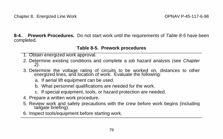
Chapter 8. Energized Line Work OPNAV P-45-117-6-98
79
8-4. Prework Procedures. Do not start work until the requirements of Table 8-5 have beencompleted.
Table 8-5. Prework procedures1. Obtain energized work approval.2. Determine existing conditions and complete a job hazard analysis (see Chapter
2).3. Determine the voltage rating of circuits to be worked on, distances to other
energized lines, and location of work. Evaluate the following:a. If aerial lift equipment can be used.b. What personnel qualifications are needed for the work.c. If special equipment, tools, or hazard protection are needed.
4. Prepare a written work procedure.5. Review work and safety precautions with the crew before work begins (including
tailgate briefing).6. Inspect tools/equipment before starting work.
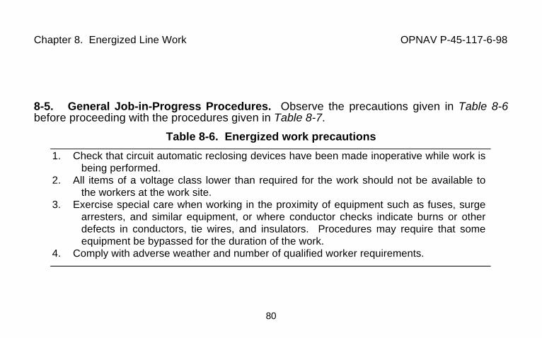
Chapter 8. Energized Line Work OPNAV P-45-117-6-98
80
8-5. General Job-in-Progress Procedures. Observe the precautions given in Table 8-6before proceeding with the procedures given in Table 8-7.
Table 8-6. Energized work precautions
1. Check that circuit automatic reclosing devices have been made inoperative while work isbeing performed.
2. All items of a voltage class lower than required for the work should not be available tothe workers at the work site.
3. Exercise special care when working in the proximity of equipment such as fuses, surgearresters, and similar equipment, or where conductor checks indicate burns or otherdefects in conductors, tie wires, and insulators. Procedures may require that someequipment be bypassed for the duration of the work.
4. Comply with adverse weather and number of qualified worker requirements.
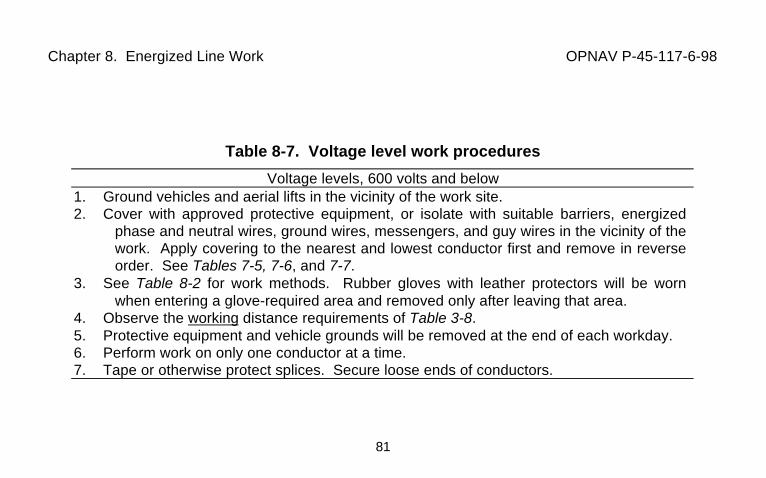
Chapter 8. Energized Line Work OPNAV P-45-117-6-98
81
Table 8-7. Voltage level work procedures
Voltage levels, 600 volts and below1. Ground vehicles and aerial lifts in the vicinity of the work site.2. Cover with approved protective equipment, or isolate with suitable barriers, energized
phase and neutral wires, ground wires, messengers, and guy wires in the vicinity of thework. Apply covering to the nearest and lowest conductor first and remove in reverseorder. See Tables 7-5, 7-6, and 7-7.
3. See Table 8-2 for work methods. Rubber gloves with leather protectors will be wornwhen entering a glove-required area and removed only after leaving that area.
4. Observe the working distance requirements of Table 3-8.5. Protective equipment and vehicle grounds will be removed at the end of each workday.6. Perform work on only one conductor at a time.7. Tape or otherwise protect splices. Secure loose ends of conductors.
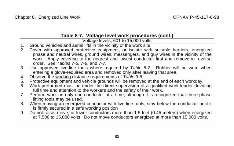
Chapter 8. Energized Line Work OPNAV P-45-117-6-98
82
Table 8-7. Voltage level work procedures (cont.)Voltage levels, 601 to 15,000 volts
1. Ground vehicles and aerial lifts in the vicinity of the work site.2. Cover with approved protective equipment, or isolate with suitable barriers, energized
phase and neutral wires, ground wires, messengers, and guy wires in the vicinity of thework. Apply covering to the nearest and lowest conductor first and remove in reverseorder. See Tables 7-5, 7-6, and 7-7.
3. Use approved live-line tools where required by Table 8-2. Rubber will be worn whenentering a glove-required area and removed only after leaving that area.
4. Observe the working distance requirements of Table 3-8.5. Protective equipment and vehicle grounds will be removed at the end of each workday.6. Work performed must be under the direct supervision of a qualified work leader devoting
full time and attention to the workers and the safety of their work.7. Perform work on only one conductor at a time, although it is recognized that three-phase
lifting tools may be used.8. When moving an energized conductor with live-line tools, stay below the conductor until it
is firmly secured in a safe working position9. Do not raise, move, or lower conductors more than 1.5 feet (0.45 meters) when energized
at 7,500 to 15,000 volts. Do not move conductors energized at more than 15,000 volts.
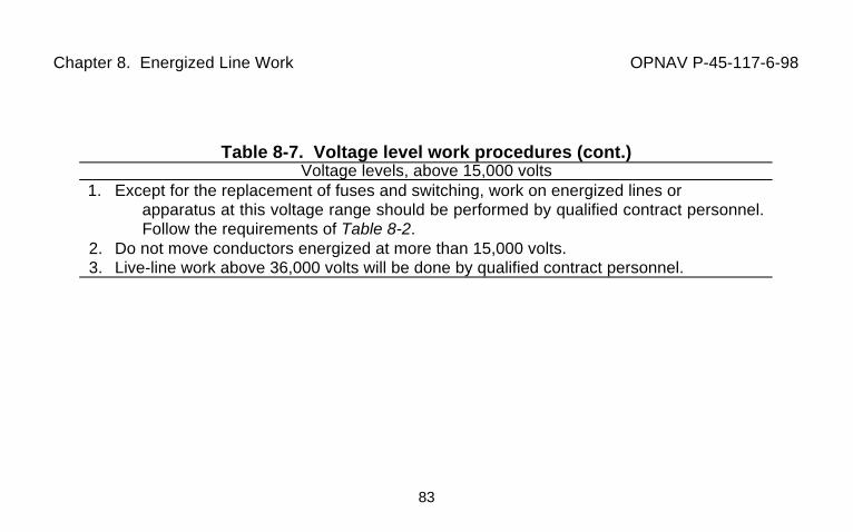
Chapter 8. Energized Line Work OPNAV P-45-117-6-98
83
Table 8-7. Voltage level work procedures (cont.)Voltage levels, above 15,000 volts
1. Except for the replacement of fuses and switching, work on energized lines or apparatus at this voltage range should be performed by qualified contract personnel.Follow the requirements of Table 8-2.
2. Do not move conductors energized at more than 15,000 volts.3. Live-line work above 36,000 volts will be done by qualified contract personnel.
Chapter 9. Substations and Switchgear OPNAV P-45-117-6-98
84
CHAPTER 9. SUBSTATIONS AND SWITCHGEAR9-1. Safety Precautions. Review the applicable safety rules given in MIL-HDBK 1025/10for outdoor substations and interior medium-voltage systems for the specific safety rulesapplying to the work which you will be doing. Ensure that everyone is alerted to possible jobhazards and is aware of their responsibilities. Discuss any question you have at your tailgatebriefing before the job is started (See Table 2-4).
9-2. Major Equipment Hazards and Safety Precautions. Each type of equipment has itsown safety rules. Table 9-1 summarizes safety reminders. Essential to all safe operations isthe use of proper protective equipment, knowledge of the manufacturer’s safety instructions,and correct identification of the devices worked on.
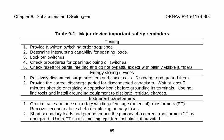
Chapter 9. Substations and Switchgear OPNAV P-45-117-6-98
85
Table 9-1. Major device important safety reminders
Testing1. Provide a written switching order sequence.2. Determine interrupting capability for opening loads.3. Lock out switches.4. Check procedures for opening/closing oil switches.5. Check fuses for partial melting and do not bypass, except with plainly visible jumpers.
Energy storing devices1. Positively disconnect surge arresters and choke coils. Discharge and ground them.
2. Provide the correct discharge period for disconnected capacitors. Wait at least 5 minutes after de-energizing a capacitor bank before grounding its terminals. Use hot-line tools and install grounding equipment to dissipate residual charges.
Instrument transformers1. Ground case and one secondary winding of voltage (potential) transformers (PT).
Remove secondary fuses before replacing primary fuses.2. Short secondary leads and ground them if the primary of a current transformer (CT) is
energized. Use a CT short-circuiting type terminal block, if provided.
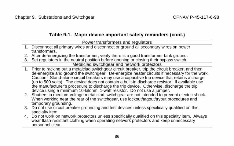
Chapter 9. Substations and Switchgear OPNAV P-45-117-6-98
86
Table 9-1. Major device important safety reminders (cont.)
Power transformers and regulators1. Disconnect all primary wires and disconnect or ground all secondary wires on power
transformers.2. After de-energizing the transformer, verify there is a good transformer tank ground.3. Set regulators in the neutral position before opening or closing their bypass switch.
Metalclad switchgear and network protectors1. Prior to racking out a metalclad switchgear circuit breaker, trip the circuit breaker, and then
de-energize and ground the switchgear. De-energize heater circuits if necessary for the work.Caution: Stand-alone circuit breakers may use a capacitive trip device that retains a charge(up to 500 volts). The device does not contain a built-in discharge resistor. If available usethe manufacturer’s procedure to discharge the trip device. Otherwise, discharge the tripdevice using a minimum 10-kilohm, 1-watt resistor. Do not use a jumper.
2. Shutters in medium-voltage metal clad switchgear are not intended to prevent electric shock. When working near the rear of the switchgear, use lockout/tagout/tryout procedures and temporary grounding.
3. Do not use circuit breaker grounding and test devices unless specifically qualified on thisspecialty item.
4. Do not work on network protectors unless specifically qualified on this specialty item. Alwayswear flash-resistant clothing when operating network protectors and keep unnecessarypersonnel clear.
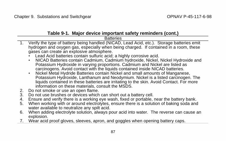
Chapter 9. Substations and Switchgear OPNAV P-45-117-6-98
87
Table 9-1. Major device important safety reminders (cont.)Batteries
1. Verify the type of battery being handled (NICAD, Lead Acid, etc.). Storage batteries emithydrogen and oxygen gas, especially when being charged. If contained in a room, thesegases can create an explosive atmosphere.• Lead Acid batteries contain sulfuric acid; a highly corrosive acid.• NICAD Batteries contain Cadmium, Cadmium hydroxide, Nickel, Nickel Hydroxide and
Potassium Hydroxide in varying proportions. Cadmium and Nickel are listed ascarcinogens. Avoid contact with the liquids contained inside NICAD batteries.
• Nickel Metal Hydride Batteries contain Nickel and small amounts of Manganese,Potassium Hydroxide, Lanthanum and Neodymium. Nickel is a listed carcinogen. Theliquids contained in these batteries are irritating to the skin. Avoid Contact. For moreinformation on these materials, consult the MSDS.
2. Do not smoke or use an open flame.3. Do not use brushes or devices which can short out a battery cell.4. Ensure and verify there is a working eye wash, fixed or portable, near the battery bank.5. When working with or around electrolytes, ensure there is a solution of baking soda and
water available to neutralize any spilt acid.6. When adding electrolyte solution, always pour acid into water. The reverse can cause an
explosion.7. Wear acid proof gloves, sleeves, apron, and goggles when opening battery caps.
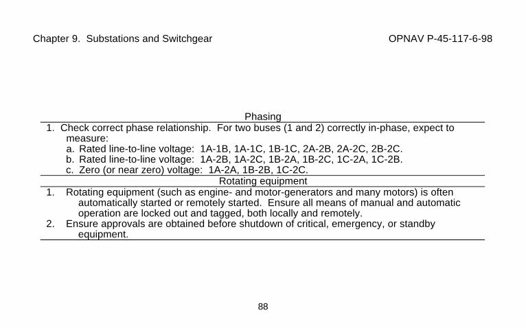
Chapter 9. Substations and Switchgear OPNAV P-45-117-6-98
88
Phasing1. Check correct phase relationship. For two buses (1 and 2) correctly in-phase, expect to
measure:a. Rated line-to-line voltage: 1A-1B, 1A-1C, 1B-1C, 2A-2B, 2A-2C, 2B-2C.b. Rated line-to-line voltage: 1A-2B, 1A-2C, 1B-2A, 1B-2C, 1C-2A, 1C-2B.c. Zero (or near zero) voltage: 1A-2A, 1B-2B, 1C-2C.
Rotating equipment1. Rotating equipment (such as engine- and motor-generators and many motors) is often
automatically started or remotely started. Ensure all means of manual and automaticoperation are locked out and tagged, both locally and remotely.
2. Ensure approvals are obtained before shutdown of critical, emergency, or standbyequipment.
Chapter 10. Aerial Lines OPNAV P-45-117-6-98
89
CHAPTER 10. AERIAL LINES10-1. Safety Precautions. Review the applicable safety rules given in MIL-HDBK 1025/10for overhead lines and associated electrical components. Ensure presite job requirements(Table 2-4) are completed. Discuss any question at the tailgate briefing before the job isstarted.
a. On-Ground Work. On-ground work is not covered in this handbook. See MIL-HDBK 1025/10 for information on pole handling and installation, and conductor stringing andremoval.
b. Above-Ground Work. Above-ground work may be accomplished from an aeriallift truck or by climbing the pole. Consider street lighting circuits as possibly energized to thehighest voltage of conductors occupying the same poles. See Subparagraph 5-1d forequipment for positioning a worker. See Subparagraph 4-2a for climbing protection andtraining. Figure 4-2 covers fall protection.
10-2. Climbing and Working on Poles. Precautions for equipment such as surge arresters,switches, fuses, capacitors and power transformers are discussed in Table 9-1.
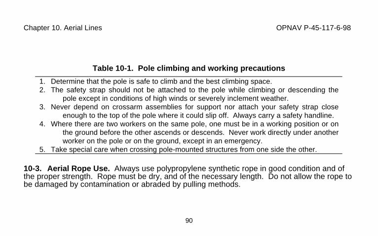
Chapter 10. Aerial Lines OPNAV P-45-117-6-98
90
Table 10-1. Pole climbing and working precautions
1. Determine that the pole is safe to climb and the best climbing space.2. The safety strap should not be attached to the pole while climbing or descending the
pole except in conditions of high winds or severely inclement weather.3. Never depend on crossarm assemblies for support nor attach your safety strap close
enough to the top of the pole where it could slip off. Always carry a safety handline.4. Where there are two workers on the same pole, one must be in a working position or on
the ground before the other ascends or descends. Never work directly under anotherworker on the pole or on the ground, except in an emergency.
5. Take special care when crossing pole-mounted structures from one side the other.
10-3. Aerial Rope Use. Always use polypropylene synthetic rope in good condition and ofthe proper strength. Rope must be dry, and of the necessary length. Do not allow the rope tobe damaged by contamination or abraded by pulling methods.
Chapter 11. Underground Lines OPNAV P-45-117-6-98
91
CHAPTER 11. UNDERGROUND LINES11-1. Safety Precautions. Review the applicable safety rules given in MIL-HDBK 1025/10for underground cables, structures, and associated electrical components. Ensure presite jobrequirements (Table 2-4) are completed. Develop specific rules for each task based onequipment condition and reliability. Discuss any questions at the tailgate briefing before thejob is started.
a. Worker Protection. Experience proves the importance of following safetyprecautions for electrical work in confined spaces. In one incidence in a confined space, fiveNavy civilian workers were injured, one fatally and two seriously, when the electrical systemthey were repairing failed catastrophically. Treat underground structures such as manholesand unvented vaults as confined spaces and conform to the requirements of OPNAVINST5100.23, (Confined Space Entry Program). Treat these structures as Permit-requiredconfined spaces and conform to the requirements for testing/monitoring, ventilation,attendants, respiratory protection, personal protective equipment, and training. Provide thenumber of workers required by Tables 3-10 and 3-11 as a minimum. Illumination will not beless than the minimums given in Table 3-1.
b. Public Safety. Protect the public around the work area in accordance withSubparagraph 3-1b.
c. Existing Utility Protection. Locate and mark existing utilities in work areaswhere excavations are to be made. Digging restrictions may apply. Coordinate with theappropriate maintenance group or the fire department for unexpected hazards.
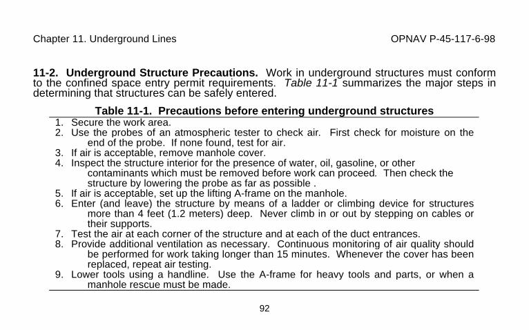
Chapter 11. Underground Lines OPNAV P-45-117-6-98
92
11-2. Underground Structure Precautions. Work in underground structures must conformto the confined space entry permit requirements. Table 11-1 summarizes the major steps indetermining that structures can be safely entered.
Table 11-1. Precautions before entering underground structures1. Secure the work area.2. Use the probes of an atmospheric tester to check air. First check for moisture on the
end of the probe. If none found, test for air.3. If air is acceptable, remove manhole cover.4. Inspect the structure interior for the presence of water, oil, gasoline, or other
contaminants which must be removed before work can proceed. Then check thestructure by lowering the probe as far as possible .
5. If air is acceptable, set up the lifting A-frame on the manhole.6. Enter (and leave) the structure by means of a ladder or climbing device for structures
more than 4 feet (1.2 meters) deep. Never climb in or out by stepping on cables ortheir supports.
7. Test the air at each corner of the structure and at each of the duct entrances.8. Provide additional ventilation as necessary. Continuous monitoring of air quality should
be performed for work taking longer than 15 minutes. Whenever the cover has beenreplaced, repeat air testing.
9. Lower tools using a handline. Use the A-frame for heavy tools and parts, or when amanhole rescue must be made.
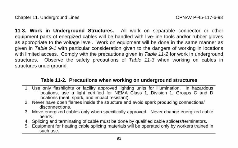
Chapter 11. Underground Lines OPNAV P-45-117-6-98
93
11-3. Work in Underground Structures. All work on separable connector or otherequipment parts of energized cables will be handled with live-line tools and/or rubber glovesas appropriate to the voltage level. Work on equipment will be done in the same manner asgiven in Table 9-1 with particular consideration given to the dangers of working in locationswith limited access. Comply with the precautions given in Table 11-2 for work in undergroundstructures. Observe the safety precautions of Table 11-3 when working on cables instructures underground.
Table 11-2. Precautions when working on underground structures
1. Use only flashlights or facility approved lighting units for illumination. In hazardouslocations, use a light certified for NEMA Class 1, Division 1, Groups C and Dlocations (heat, spark, and impact resistant).
2. Never have open flames inside the structure and avoid spark producing connections/disconnections.
3. Move energized cables only when specifically approved. Never change energized cablebends.
4. Splicing and terminating of cable must be done by qualified cable splicers/terminators.5. Equipment for heating cable splicing materials will be operated only by workers trained in
such use.
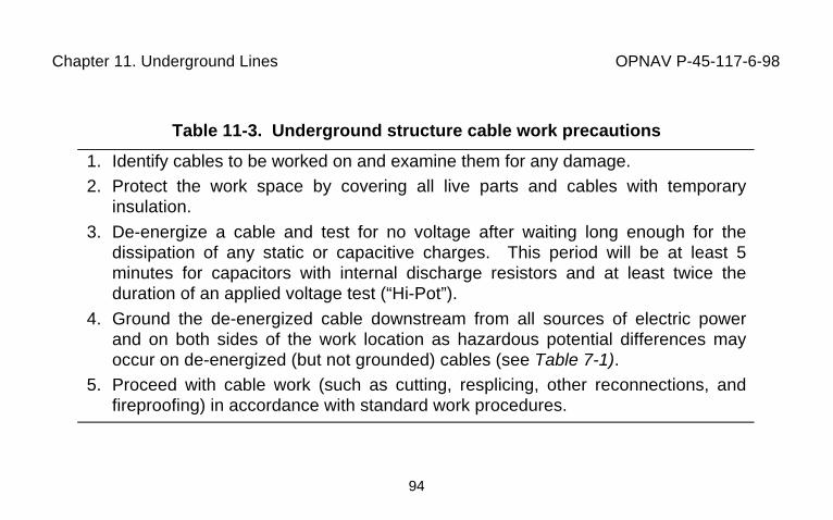
Chapter 11. Underground Lines OPNAV P-45-117-6-98
94
Table 11-3. Underground structure cable work precautions
1. Identify cables to be worked on and examine them for any damage.2. Protect the work space by covering all live parts and cables with temporary
insulation.
3. De-energize a cable and test for no voltage after waiting long enough for thedissipation of any static or capacitive charges. This period will be at least 5minutes for capacitors with internal discharge resistors and at least twice theduration of an applied voltage test (“Hi-Pot”).
4. Ground the de-energized cable downstream from all sources of electric powerand on both sides of the work location as hazardous potential differences mayoccur on de-energized (but not grounded) cables (see Table 7-1).
5. Proceed with cable work (such as cutting, resplicing, other reconnections, andfireproofing) in accordance with standard work procedures.
Chapter 12. Shore-To-Ship Electrical Power Connections OPNAV P-45-117-6-98
95
CHAPTER 12 SHORE-TO-SHIP ELECTRICAL POWER CONNECTIONS12-1 Safety Precautions. Review the applicable safety rules given in MIL-HDBK 1025/10Handbook For Electrical Transmission And Distribution Safety (Chapter 13, Shore-To-ShipElectrical Power Connections) for specific safety rules applying to the work you will be doing.Ensure that everyone is alert to possible job hazards and is aware of their responsibilities.Discuss any questions you have at your tailgate briefing before the job is started (See Table2-4).
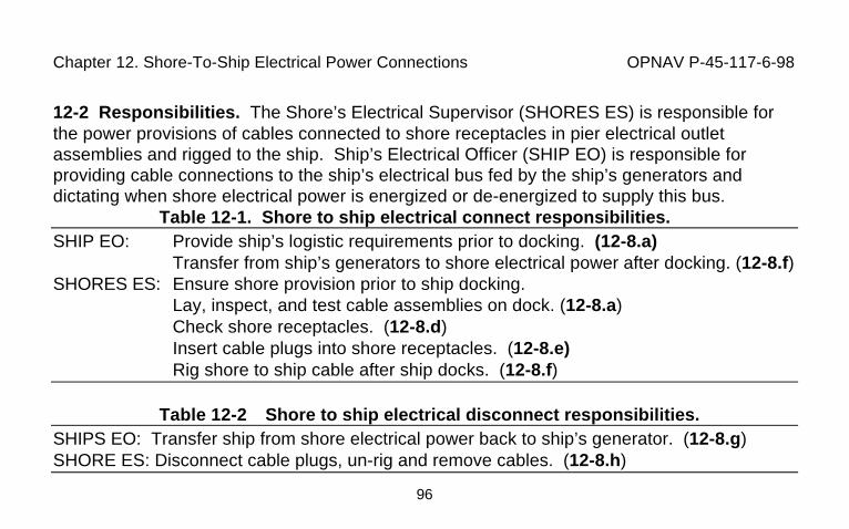
Chapter 12. Shore-To-Ship Electrical Power Connections OPNAV P-45-117-6-98
96
12-2 Responsibilities. The Shore’s Electrical Supervisor (SHORES ES) is responsible forthe power provisions of cables connected to shore receptacles in pier electrical outletassemblies and rigged to the ship. Ship’s Electrical Officer (SHIP EO) is responsible forproviding cable connections to the ship’s electrical bus fed by the ship’s generators anddictating when shore electrical power is energized or de-energized to supply this bus.
Table 12-1. Shore to ship electrical connect responsibilities.SHIP EO: Provide ship’s logistic requirements prior to docking. (12-8.a)
Transfer from ship’s generators to shore electrical power after docking. (12-8.f)SHORES ES: Ensure shore provision prior to ship docking.
Lay, inspect, and test cable assemblies on dock. (12-8.a)Check shore receptacles. (12-8.d)Insert cable plugs into shore receptacles. (12-8.e)Rig shore to ship cable after ship docks. (12-8.f)
Table 12-2 Shore to ship electrical disconnect responsibilities.SHIPS EO: Transfer ship from shore electrical power back to ship’s generator. (12-8.g)SHORE ES: Disconnect cable plugs, un-rig and remove cables. (12-8.h)
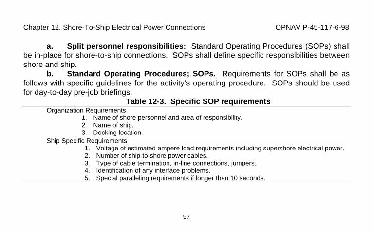
Chapter 12. Shore-To-Ship Electrical Power Connections OPNAV P-45-117-6-98
97
a. Split personnel responsibilities: Standard Operating Procedures (SOPs) shallbe in-place for shore-to-ship connections. SOPs shall define specific responsibilities betweenshore and ship.
b. Standard Operating Procedures; SOPs. Requirements for SOPs shall be asfollows with specific guidelines for the activity’s operating procedure. SOPs should be usedfor day-to-day pre-job briefings.
Table 12-3. Specific SOP requirementsOrganization Requirements
1. Name of shore personnel and area of responsibility.2. Name of ship.3. Docking location.
Ship Specific Requirements1. Voltage of estimated ampere load requirements including supershore electrical power.2. Number of ship-to-shore power cables.3. Type of cable termination, in-line connections, jumpers.4. Identification of any interface problems.5. Special paralleling requirements if longer than 10 seconds.
Chapter 12. Shore-To-Ship Electrical Power Connections OPNAV P-45-117-6-98
98
c. Preparation responsibility. The activity responsible for shore-to-ship electricalservice shall prepare general SOPs with a section for individual organization requirements.Requirements are to be correctly filled in for each specific ship’s service and service period.Distribution is to be to all personnel involved.
12-3 Distribution Systems. Specific safety requirements given apply to the cableassemblies from pier’s electrical outlet assemblies (turtlebacks) to ship’s electrical bus.
a. Shore medium-voltage distribution system. Pier primary electricaldistribution systems normally operate in the medium-voltage range of 5 kV and 35 kV. Figure12-1 provides an example of an electrical connection outlet assembly with a 15-kV receptacle.For permanent pier service, dual primary feeders are preferred. Pier systems may befurnished with single feeders. The feeders serve substations which stepdown the distributionsystem’s primary voltage to the secondary voltage for ship service of 480 volts or 4.16 kV(See Figures 12-4 and 12-5).
b. Low voltage distribution system. (See Figure 12-4).
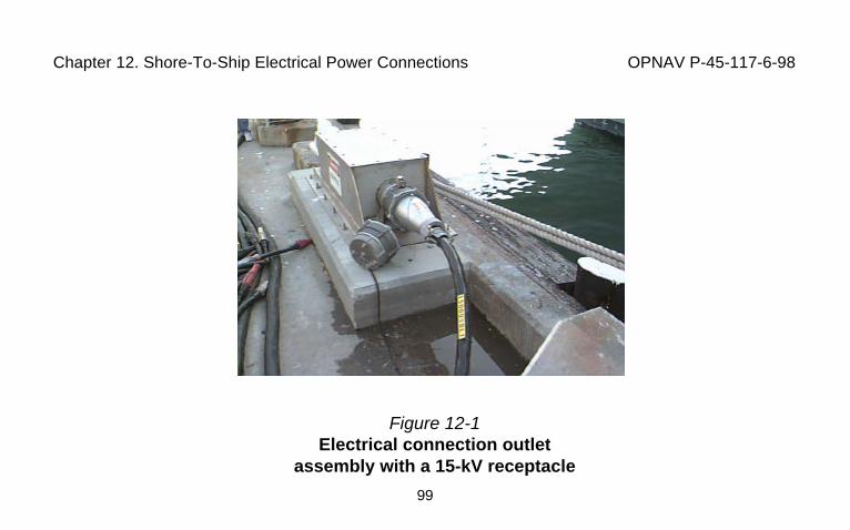
Chapter 12. Shore-To-Ship Electrical Power Connections OPNAV P-45-117-6-98
99
Figure 12-1Electrical connection outlet
assembly with a 15-kV receptacle
Chapter 12. Shore-To-Ship Electrical Power Connections OPNAV P-45-117-6-98
100
12-4 Substation Assemblies. There are two types of substations; nonfixed, which areinstalled on the top of the pier, and fixed which are installed in vaults under the pier.
a. Nonfixed pier substations: (See Figure 12-2) are skid mounted and fed from ashore installation substation consisting of a medium voltage disconnect assembly. They aresupplied by primary cable assemblies installed on the pier and connected to the electricaldistribution system source and the substation by primary voltage pier coupler plugs andreceptacles in electrical connection outlet assemblies.
b. Fixed pier substations: (See Figure 12-3) are fed by primary cables installedin duct lines. Both types of substations contain primary switch(es), a step-down transformer,and secondary circuit breakers supplying the pier electrical outlet assemblies.
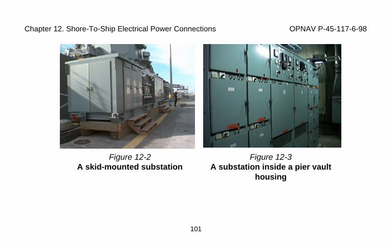
Chapter 12. Shore-To-Ship Electrical Power Connections OPNAV P-45-117-6-98
101
Figure 12-2A skid-mounted substation
Figure 12-3A substation inside a pier vault
housing

Chapter 12. Shore-To-Ship Electrical Power Connections OPNAV P-45-117-6-98
102
c. Working Space. NEC Definitions:1. Underground Vaults: equipment in underground vaults is not readily
assessable and may not meet current NEC work space requirements. Workers in vaults needto meet confined space requirements of OPNAVINST 5100.23 (Confined Space EntryProgram), 29 CFR 1910.146 (Permit Required Confined Spaces), and/or 29 CFR 1910.269(t)(Electric Power Generation, Transmission, and Distribution: Enclosed Space).
2. Readily Accessible: equipment that is capable of being reached quickly foroperation, without requiring climbing over obstacles, using portable ladders, chairs, or otherdevices to reach the equipment.
3. Working Space: sufficient access provided and maintained about all electricequipment to permit ready and safe operation and maintenance. Working space in vaults isprovided in accordance with NEC requirements at time of construction. Vaults built perviousto NEC requirements do not fall into current requirements. Each activity shall evaluate thesespaces for their effect on worker safety and provide SOPs as necessary to assure safeworking conditions.
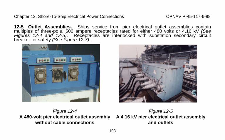
Chapter 12. Shore-To-Ship Electrical Power Connections OPNAV P-45-117-6-98
103
12-5 Outlet Assemblies. Ships service from pier electrical outlet assemblies containmultiples of three-pole, 500 ampere receptacles rated for either 480 volts or 4.16 kV (SeeFigures 12-4 and 12-5). Receptacles are interlocked with substation secondary circuitbreaker for safety (See Figure 12-7).
Figure 12-4A 480-volt pier electrical outlet assembly
without cable connections
Figure 12-5A 4.16 kV pier electrical outlet assembly
and outlets
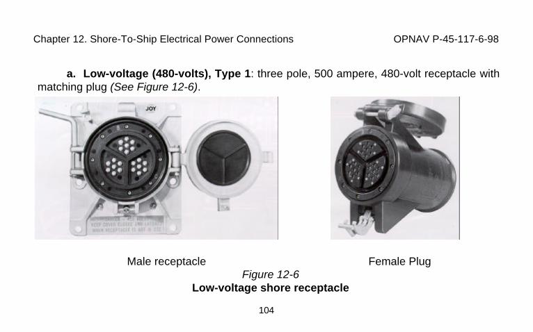
Chapter 12. Shore-To-Ship Electrical Power Connections OPNAV P-45-117-6-98
104
a. Low-voltage (480-volts), Type 1: three pole, 500 ampere, 480-volt receptacle withmatching plug (See Figure 12-6).
Male receptacle Female PlugFigure 12-6
Low-voltage shore receptacle
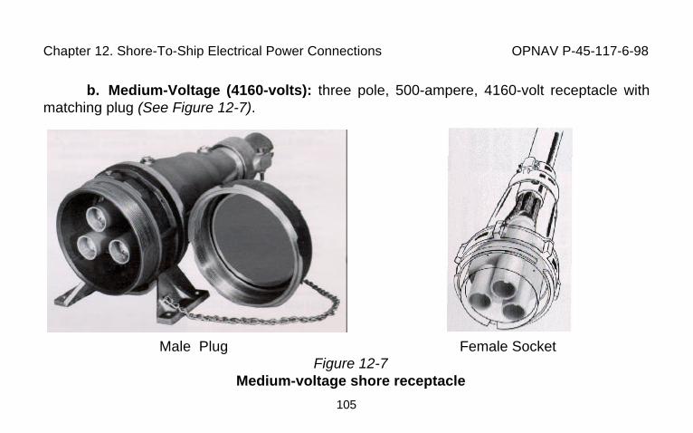
Chapter 12. Shore-To-Ship Electrical Power Connections OPNAV P-45-117-6-98
105
b. Medium-Voltage (4160-volts): three pole, 500-ampere, 4160-volt receptacle withmatching plug (See Figure 12-7).
Male Plug Female SocketFigure 12-7
Medium-voltage shore receptacle
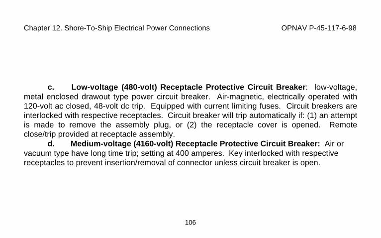
Chapter 12. Shore-To-Ship Electrical Power Connections OPNAV P-45-117-6-98
106
c. Low-voltage (480-volt) Receptacle Protective Circuit Breaker: low-voltage,metal enclosed drawout type power circuit breaker. Air-magnetic, electrically operated with120-volt ac closed, 48-volt dc trip. Equipped with current limiting fuses. Circuit breakers areinterlocked with respective receptacles. Circuit breaker will trip automatically if: (1) an attemptis made to remove the assembly plug, or (2) the receptacle cover is opened. Remoteclose/trip provided at receptacle assembly.
d. Medium-voltage (4160-volt) Receptacle Protective Circuit Breaker: Air orvacuum type have long time trip; setting at 400 amperes. Key interlocked with respectivereceptacles to prevent insertion/removal of connector unless circuit breaker is open.
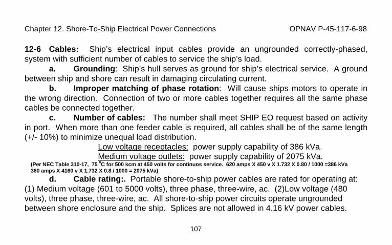
Chapter 12. Shore-To-Ship Electrical Power Connections OPNAV P-45-117-6-98
107
12-6 Cables: Ship’s electrical input cables provide an ungrounded correctly-phased,system with sufficient number of cables to service the ship’s load.
a. Grounding: Ship’s hull serves as ground for ship’s electrical service. A groundbetween ship and shore can result in damaging circulating current.
b. Improper matching of phase rotation: Will cause ships motors to operate inthe wrong direction. Connection of two or more cables together requires all the same phasecables be connected together.
c. Number of cables: The number shall meet SHIP EO request based on activityin port. When more than one feeder cable is required, all cables shall be of the same length(+/- 10%) to minimize unequal load distribution.
Low voltage receptacles: power supply capability of 386 kVa.Medium voltage outlets: power supply capability of 2075 kVa.
(Per NEC Table 310-17, 75 0C for 500 kcm at 450 volts for continuos service. 620 amps X 450 v X 1.732 X 0.80 / 1000 =386 kVa360 amps X 4160 v X 1.732 X 0.8 / 1000 = 2075 kVa)
d. Cable rating:. Portable shore-to-ship power cables are rated for operating at:(1) Medium voltage (601 to 5000 volts), three phase, three-wire, ac. (2)Low voltage (480volts), three phase, three-wire, ac. All shore-to-ship power circuits operate ungroundedbetween shore enclosure and the ship. Splices are not allowed in 4.16 kV power cables.
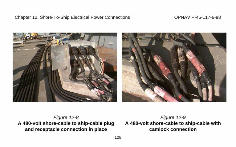
Chapter 12. Shore-To-Ship Electrical Power Connections OPNAV P-45-117-6-98
108
Figure 12-8A 480-volt shore-cable to ship-cable plug
and receptacle connection in place
Figure 12-9A 480-volt shore-cable to ship-cable with
camlock connection
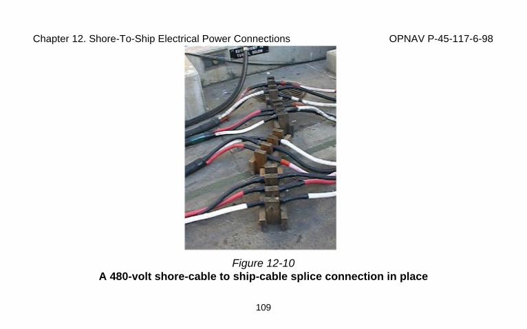
Chapter 12. Shore-To-Ship Electrical Power Connections OPNAV P-45-117-6-98
109
Figure 12-10A 480-volt shore-cable to ship-cable splice connection in place
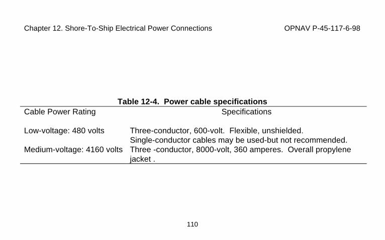
Chapter 12. Shore-To-Ship Electrical Power Connections OPNAV P-45-117-6-98
110
Table 12-4. Power cable specificationsCable Power Rating Specifications
Low-voltage: 480 volts Three-conductor, 600-volt. Flexible, unshielded.Single-conductor cables may be used-but not recommended.
Medium-voltage: 4160 volts Three -conductor, 8000-volt, 360 amperes. Overall propylenejacket .
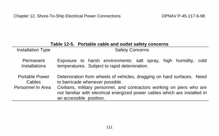
Chapter 12. Shore-To-Ship Electrical Power Connections OPNAV P-45-117-6-98
111
Table 12-5. Portable cable and outlet safety concernsInstallation Type Safety Concerns
PermanentInstallations
Exposure to harsh environments: salt spray, high humidity, coldtemperatures. Subject to rapid deterioration.
Portable PowerCables
Deterioration from wheels of vehicles, dragging on hard surfaces. Needto barricade whenever possible.
Personnel In Area Civilians, military personnel, and contractors working on piers who arenot familiar with electrical energized power cables which are installed inan accessible position.
Chapter 12. Shore-To-Ship Electrical Power Connections OPNAV P-45-117-6-98
112
12-7 Circuit Arrangementsa. Service Component Diagrams. (See Figure 12-11: diagram of the physical
relation of ship and power connections to the pier electrical power service). Ships may have 1,2, or 3 service ports requiring connections. Power cables provided must be of equal length(within + or - 10%) and without sharp bends. Power cables may need additional protection;(See Table 12-9).
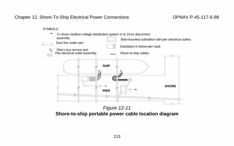
Chapter 12. Shore-To-Ship Electrical Power Connections OPNAV P-45-117-6-98
113
Figure 12-11Shore-to-ship portable power cable location diagram
SYMBOLS
To shore medium-voltage distribution system or to 15-kv disconnectassembly
Duct line under pier
Pier electrical outlet assembly
Substation in below pier vaultShip’s bus service port
Skid-mounted substation with pier electrical outlets
Shore-to-ship cables
SHOREPIER
SHIP
Chapter 12. Shore-To-Ship Electrical Power Connections OPNAV P-45-117-6-98
114
b. Preferred ship-to-shore circuit arrangement. (See Figure 12-12: Simplifiedone-line diagram of ship’s main electrical service components). Note Chapters 9 and 11 forsafety requirements. This circuit diagram is similar for skid-mounted substations exceptwithout vault requirements. Pier outlet assemblies may be part of a skid-mount substation.
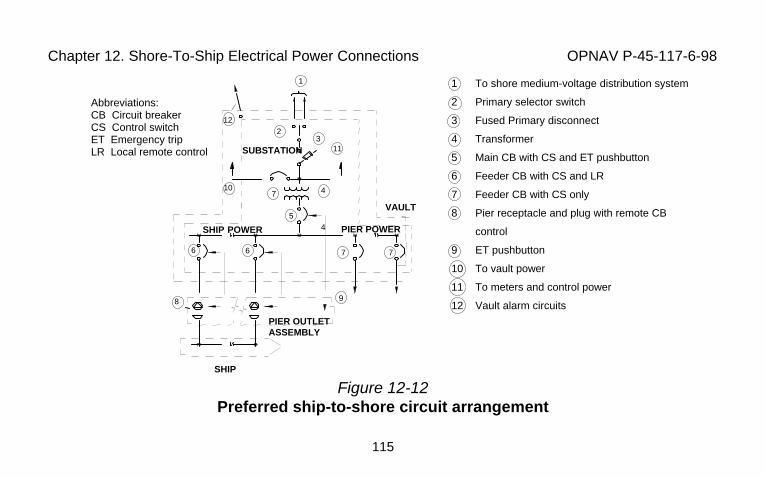
Chapter 12. Shore-To-Ship Electrical Power Connections OPNAV P-45-117-6-98
115
Figure 12-12Preferred ship-to-shore circuit arrangement
1 To shore medium-voltage distribution system
2 Primary selector switch
3 Fused Primary disconnect
4 Transformer
5 Main CB with CS and ET pushbutton
6 Feeder CB with CS and LR
7 Feeder CB with CS only
8 Pier receptacle and plug with remote CB
control
9 ET pushbutton
10 To vault power
11 To meters and control power
12 Vault alarm circuits
Abbreviations:CB Circuit breakerCS Control switchET Emergency tripLR Local remote control
VAULT
SHIP
PIER OUTLETASSEMBLY
SHIP POWER PIER POWER
SUBSTATION
122
10
311
7
45
6 6 7 7
98
1
4
Chapter 12. Shore-To-Ship Electrical Power Connections OPNAV P-45-117-6-98
116
c. Ship energizing safety procedures: (See Figure 12-13: Procedures in safelyenergizing a ship from a shore electrical circuit), are to be followed to assure that energizingthe ship is done in a safe manner. Responsibilities for the connection of portable powercables to shore electrical receptacles and ship electrical buses are covered in section 12-2.
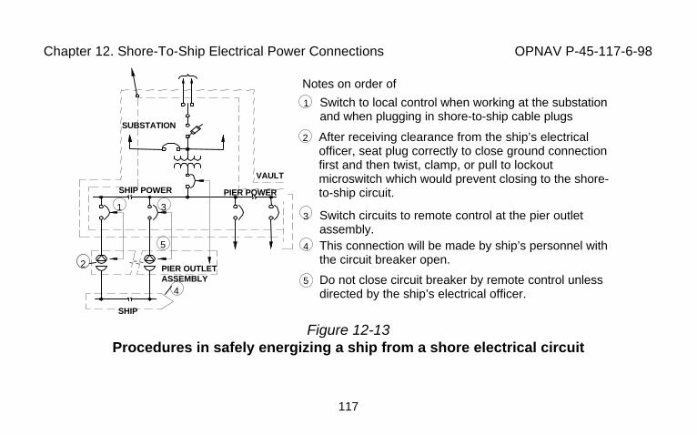
Chapter 12. Shore-To-Ship Electrical Power Connections OPNAV P-45-117-6-98
117
Figure 12-13Procedures in safely energizing a ship from a shore electrical circuit
Notes on order ofprocedure1 Switch to local control when working at the substation
and when plugging in shore-to-ship cable plugs
2 After receiving clearance from the ship’s electricalofficer, seat plug correctly to close ground connectionfirst and then twist, clamp, or pull to lockoutmicroswitch which would prevent closing to the shore-to-ship circuit.
3 Switch circuits to remote control at the pier outletassembly.
4 This connection will be made by ship’s personnel withthe circuit breaker open.
5 Do not close circuit breaker by remote control unlessdirected by the ship’s electrical officer.
SHIP
PIER OUTLETASSEMBLY
SHIP POWER PIER POWER
SUBSTATION
2
3
4
5
1
VAULT
Chapter 12. Shore-To-Ship Electrical Power Connections OPNAV P-45-117-6-98
118
d. Parallel Operation: Parallel operation of ship’s generators and shore powersystem is prohibited except to allow load transfer to or from shore power. Transfer timeshould not exceed 10 seconds. Paralleling shore transformers through ship’s electrical buswithout prior activity approval is a violation of safety practices and may result in circulatingcurrents, overheated cables, unbalanced loads, and excessive shore circuit current. Thiscould result in property damage and injury to personnel.
Chapter 12. Shore-To-Ship Electrical Power Connections OPNAV P-45-117-6-98
119
12-8 Connection/Disconnection ProceduresPriorities: Prior to rigging cables, consideration of the following shall be given:
1. Verify that there are no unusual job hazards present.2. Verify that boom trucks, cranes, and forklifts are properly rigged.3. Verify that the location has been given structural approval by the
facility engineer.4. Verify that construction work will not interfere with power cable
placement and rigging.Special safety provisions:
1. Barricades: required to protect cables from damage. Consider events suchas contractor work which may have vehicles, equipment placement in area, and welcomingcrowds at ship’s homecoming. Maintain safe distance, Table 3-8. Note safety hazardinformation on all cables in conformance with activity requirements.
2. Pier vault access: if possibility of vault access is required, have emergencyrescue equipment readily available (See Figure 12-14).
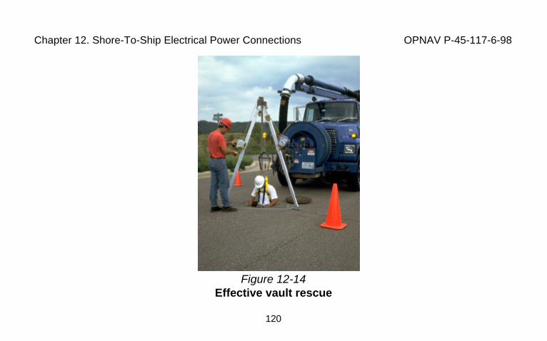
Chapter 12. Shore-To-Ship Electrical Power Connections OPNAV P-45-117-6-98
120
Figure 12-14Effective vault rescue
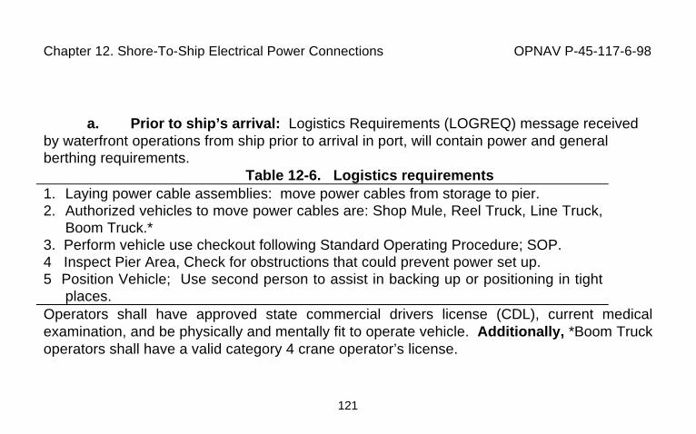
Chapter 12. Shore-To-Ship Electrical Power Connections OPNAV P-45-117-6-98
121
a. Prior to ship’s arrival: Logistics Requirements (LOGREQ) message receivedby waterfront operations from ship prior to arrival in port, will contain power and generalberthing requirements.
Table 12-6. Logistics requirements1. Laying power cable assemblies: move power cables from storage to pier.2. Authorized vehicles to move power cables are: Shop Mule, Reel Truck, Line Truck,
Boom Truck.*3. Perform vehicle use checkout following Standard Operating Procedure; SOP.4 Inspect Pier Area, Check for obstructions that could prevent power set up.5 Position Vehicle; Use second person to assist in backing up or positioning in tight
places.Operators shall have approved state commercial drivers license (CDL), current medicalexamination, and be physically and mentally fit to operate vehicle. Additionally, *Boom Truckoperators shall have a valid category 4 crane operator’s license.
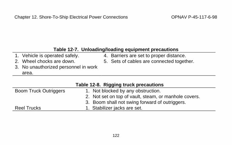
Chapter 12. Shore-To-Ship Electrical Power Connections OPNAV P-45-117-6-98
122
Table 12-7. Unloading/loading equipment precautions1. Vehicle is operated safely.2. Wheel chocks are down.3. No unauthorized personnel in work
area.
4. Barriers are set to proper distance.5. Sets of cables are connected together.
Table 12-8. Rigging truck precautionsBoom Truck Outriggers 1. Not blocked by any obstruction.
2. Not set on top of vault, steam, or manhole covers.3. Boom shall not swing forward of outriggers.
Reel Trucks 1. Stabilizer jacks are set.
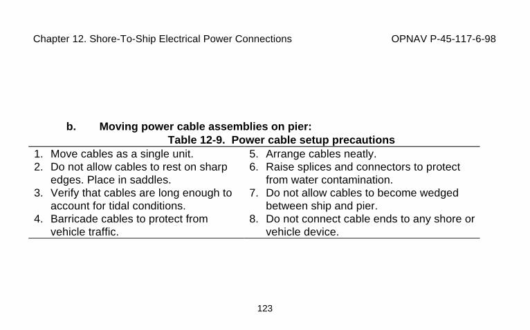
Chapter 12. Shore-To-Ship Electrical Power Connections OPNAV P-45-117-6-98
123
b. Moving power cable assemblies on pier:Table 12-9. Power cable setup precautions
1. Move cables as a single unit.2. Do not allow cables to rest on sharp
edges. Place in saddles.3. Verify that cables are long enough to
account for tidal conditions.4. Barricade cables to protect from
vehicle traffic.
5. Arrange cables neatly.6. Raise splices and connectors to protect
from water contamination.7. Do not allow cables to become wedged
between ship and pier.8. Do not connect cable ends to any shore or
vehicle device.
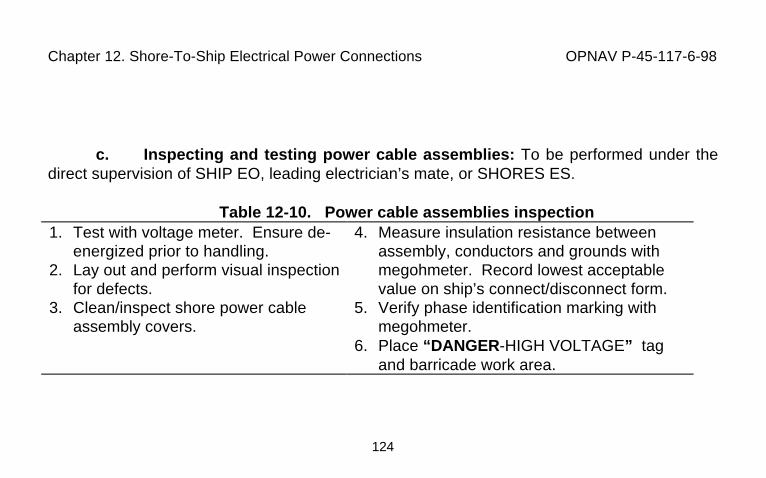
Chapter 12. Shore-To-Ship Electrical Power Connections OPNAV P-45-117-6-98
124
c. Inspecting and testing power cable assemblies: To be performed under thedirect supervision of SHIP EO, leading electrician’s mate, or SHORES ES.
Table 12-10. Power cable assemblies inspection1. Test with voltage meter. Ensure de-
energized prior to handling.2. Lay out and perform visual inspection
for defects.3. Clean/inspect shore power cable
assembly covers.
4. Measure insulation resistance betweenassembly, conductors and grounds withmegohmeter. Record lowest acceptablevalue on ship’s connect/disconnect form.
5. Verify phase identification marking withmegohmeter.
6. Place “DANGER-HIGH VOLTAGE” tagand barricade work area.
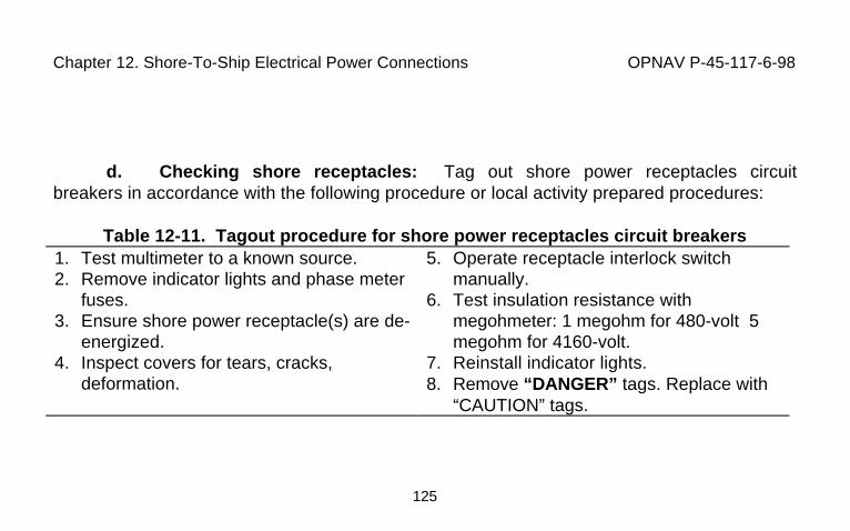
Chapter 12. Shore-To-Ship Electrical Power Connections OPNAV P-45-117-6-98
125
d. Checking shore receptacles: Tag out shore power receptacles circuitbreakers in accordance with the following procedure or local activity prepared procedures:
Table 12-11. Tagout procedure for shore power receptacles circuit breakers1. Test multimeter to a known source.2. Remove indicator lights and phase meter
fuses.3. Ensure shore power receptacle(s) are de-
energized.4. Inspect covers for tears, cracks,
deformation.
5. Operate receptacle interlock switchmanually.
6. Test insulation resistance withmegohmeter: 1 megohm for 480-volt 5megohm for 4160-volt.
7. Reinstall indicator lights.8. Remove “DANGER” tags. Replace with
“CAUTION” tags.
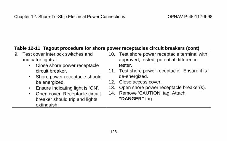
Chapter 12. Shore-To-Ship Electrical Power Connections OPNAV P-45-117-6-98
126
Table 12-11 Tagout procedure for shore power receptacles circuit breakers (cont)9. Test cover interlock switches and
indicator lights :• Close shore power receptacle
circuit breaker.• Shore power receptacle should
be energized.• Ensure indicating light is ‘ON’.• Open cover. Receptacle circuit
breaker should trip and lightsextinguish.
10. Test shore power receptacle terminal withapproved, tested, potential differencetester.
11. Test shore power receptacle. Ensure it isde-energized.
12. Close access cover.13. Open shore power receptacle breaker(s).14. Remove ‘CAUTION’ tag. Attach
“DANGER” tag.
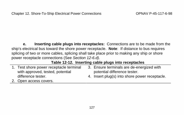
Chapter 12. Shore-To-Ship Electrical Power Connections OPNAV P-45-117-6-98
127
e. Inserting cable plugs into receptacles: Connections are to be made from theship’s electrical bus toward the shore power receptacle. Note: If distance to bus requiressplicing of two or more cables, splicing shall take place prior to making any ship or shorepower receptacle connections (See Section 12-6.d).
Table 12-12. Inserting cable plugs into receptacles1. Test shore power receptacle terminal
with approved, tested, potentialdifference tester.
2. Open access covers.
3. Ensure terminals are de-energized withpotential difference tester.
4. Insert plug(s) into shore power receptacle.
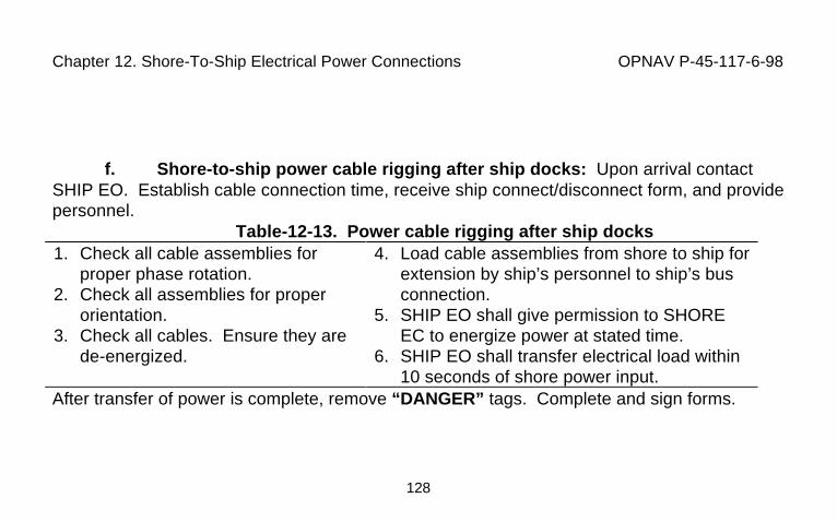
Chapter 12. Shore-To-Ship Electrical Power Connections OPNAV P-45-117-6-98
128
f. Shore-to-ship power cable rigging after ship docks: Upon arrival contactSHIP EO. Establish cable connection time, receive ship connect/disconnect form, and providepersonnel.
Table-12-13. Power cable rigging after ship docks1. Check all cable assemblies for
proper phase rotation.2. Check all assemblies for proper
orientation.3. Check all cables. Ensure they are
de-energized.
4. Load cable assemblies from shore to ship forextension by ship’s personnel to ship’s busconnection.
5. SHIP EO shall give permission to SHOREEC to energize power at stated time.
6. SHIP EO shall transfer electrical load within10 seconds of shore power input.
After transfer of power is complete, remove “DANGER” tags. Complete and sign forms.
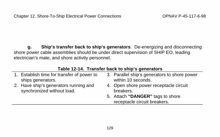
Chapter 12. Shore-To-Ship Electrical Power Connections OPNAV P-45-117-6-98
129
g. Ship’s transfer back to ship’s generators: De-energizing and disconnectingshore power cable assemblies should be under direct supervision of SHIP EO, leadingelectrician’s mate, and shore activity personnel.
Table 12-14. Transfer back to ship’s generators1. Establish time for transfer of power to
ships generators.2. Have ship’s generators running and
synchronized without load.
3. Parallel ship’s generators to shore powerwithin 10 seconds.
4. Open shore power receptacle circuitbreakers.
5. Attach “DANGER” tags to shorereceptacle circuit breakers.
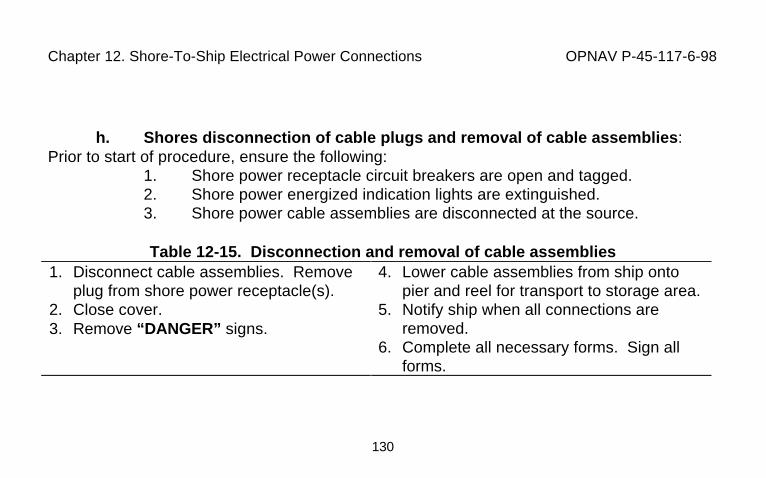
Chapter 12. Shore-To-Ship Electrical Power Connections OPNAV P-45-117-6-98
130
h. Shores disconnection of cable plugs and removal of cable assemblies:Prior to start of procedure, ensure the following:
1. Shore power receptacle circuit breakers are open and tagged.2. Shore power energized indication lights are extinguished.3. Shore power cable assemblies are disconnected at the source.
Table 12-15. Disconnection and removal of cable assemblies1. Disconnect cable assemblies. Remove
plug from shore power receptacle(s).2. Close cover.3. Remove “DANGER” signs.
4. Lower cable assemblies from ship ontopier and reel for transport to storage area.
5. Notify ship when all connections areremoved.
6. Complete all necessary forms. Sign allforms.
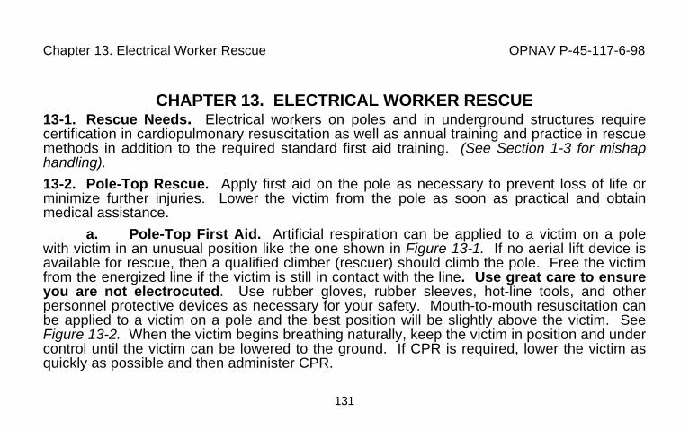
Chapter 13. Electrical Worker Rescue OPNAV P-45-117-6-98
131
CHAPTER 13. ELECTRICAL WORKER RESCUE13-1. Rescue Needs. Electrical workers on poles and in underground structures requirecertification in cardiopulmonary resuscitation as well as annual training and practice in rescuemethods in addition to the required standard first aid training. (See Section 1-3 for mishaphandling).
13-2. Pole-Top Rescue. Apply first aid on the pole as necessary to prevent loss of life orminimize further injuries. Lower the victim from the pole as soon as practical and obtainmedical assistance.
a. Pole-Top First Aid. Artificial respiration can be applied to a victim on a polewith victim in an unusual position like the one shown in Figure 13-1. If no aerial lift device isavailable for rescue, then a qualified climber (rescuer) should climb the pole. Free the victimfrom the energized line if the victim is still in contact with the line. Use great care to ensureyou are not electrocuted. Use rubber gloves, rubber sleeves, hot-line tools, and otherpersonnel protective devices as necessary for your safety. Mouth-to-mouth resuscitation canbe applied to a victim on a pole and the best position will be slightly above the victim. SeeFigure 13-2. When the victim begins breathing naturally, keep the victim in position and undercontrol until the victim can be lowered to the ground. If CPR is required, lower the victim asquickly as possible and then administer CPR.
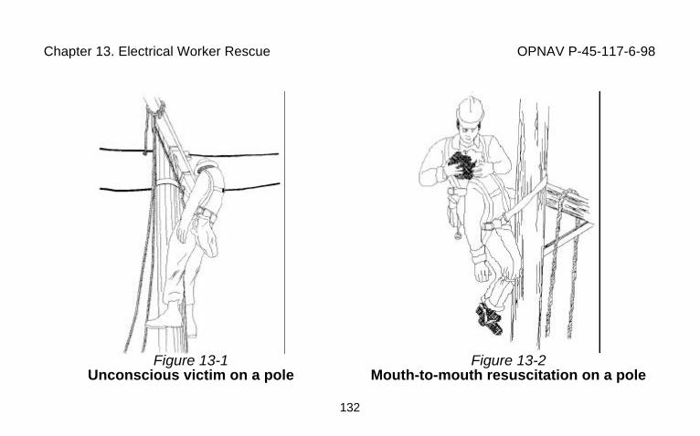
Chapter 13. Electrical Worker Rescue OPNAV P-45-117-6-98
132
Figure 13-1Unconscious victim on a pole
Figure 13-2Mouth-to-mouth resuscitation on a pole
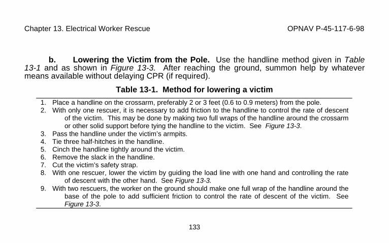
Chapter 13. Electrical Worker Rescue OPNAV P-45-117-6-98
133
b. Lowering the Victim from the Pole. Use the handline method given in Table13-1 and as shown in Figure 13-3. After reaching the ground, summon help by whatevermeans available without delaying CPR (if required).
Table 13-1. Method for lowering a victim
1. Place a handline on the crossarm, preferably 2 or 3 feet (0.6 to 0.9 meters) from the pole.2. With only one rescuer, it is necessary to add friction to the handline to control the rate of descent
of the victim. This may be done by making two full wraps of the handline around the crossarmor other solid support before tying the handline to the victim. See Figure 13-3.
3. Pass the handline under the victim’s armpits.4. Tie three half-hitches in the handline.5. Cinch the handline tightly around the victim.6. Remove the slack in the handline.7. Cut the victim’s safety strap.8. With one rescuer, lower the victim by guiding the load line with one hand and controlling the rate
of descent with the other hand. See Figure 13-3.9. With two rescuers, the worker on the ground should make one full wrap of the handline around the
base of the pole to add sufficient friction to control the rate of descent of the victim. SeeFigure 13-3.
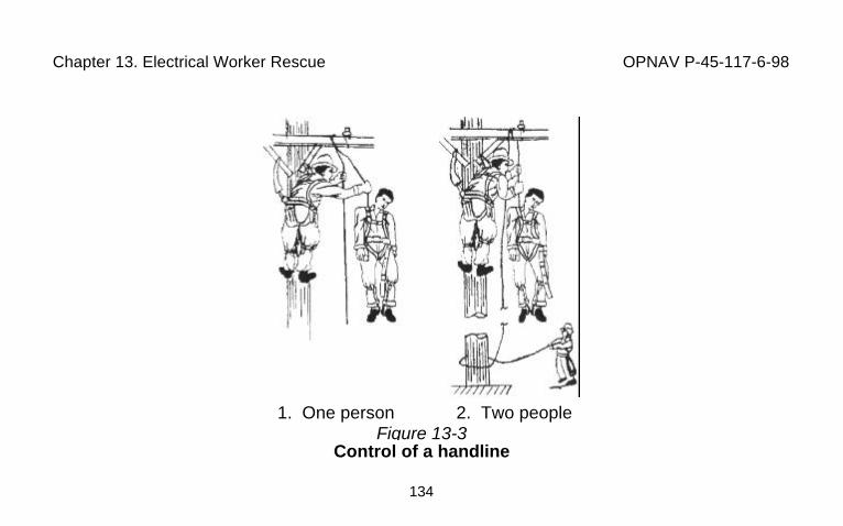
Chapter 13. Electrical Worker Rescue OPNAV P-45-117-6-98
134
1. One person 2. Two peopleFigure 13-3
Control of a handline
Chapter 13. Electrical Worker Rescue OPNAV P-45-117-6-98
135
13-3. Rescue from a Manhole. Even though normal precautions are observed, there isalways a possibility that personnel will be overcome by gas or injured, and rescue from amanhole is necessary.
a. Protect Yourself. Immediate rescue is important, but workers engaged inrescue attempts must protect themselves. In cases of asphyxiation or gas poisoning, it isadvisable to ventilate with a blower or other methods while preparing the rescue.
b. Safety Observance. All measures of safety should be observed. If at allpossible, there should be another worker present to help with the rescue before you go into amanhole. If no other worker is available, you may proceed with the rescue if you areabsolutely certain you will not become a second victim. Otherwise, obtain assistance from thefire department or other personnel trained in confined space rescue. There are many ways inwhich a rescue can be done.
13-4. Aerial Lift Rescue. Aerial lifts will be equipped to lower victims.
Appendix A OPNAV P-45-117-6-98
136
Appendix AGuide For Qualifying Personnel For Work On Or Near High Voltage Electrical
Distribution Apparatus
The following is a sample listing of electrical trades with the applicable reference to OSHA 29CFR 1910.269 sections, which must be successfully completed.
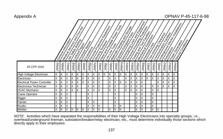
Appendix A OPNAV P-45-117-6-98
137
NOTE: Activities which have separated the responsibilities of their High Voltage Electricians into specialty groups, i.e.,overhead/underground lineman, substation/breaker/relay electrician, etc., must determine individually those sections whichdirectly apply to their employees.
Gen
eral
Info
rmat
ion
Med
ical
Ser
vice
s an
d Fi
rst A
id
Job
Safe
ty B
riefin
g
Lock
out/T
agou
tEn
clos
ed S
pace
s
Exca
vatio
nsPe
rson
al P
rote
ctiv
e Eq
uipm
ent
Wor
king
Sur
face
s
Han
d an
d Po
rtabl
e Po
wer
Too
ls
Live
-Lin
e To
ols
Mat
eria
ls H
andi
ng a
nd S
tora
ge
Expo
sed
Ener
gize
d Pa
rts
Dee
nerg
izin
g Li
nes
and
Equi
pmen
t
Pers
onal
Gro
undi
ng P
rote
ctio
n
Test
ing
and
Test
Fac
ilitie
s
Mec
hani
cal E
quip
men
t
Ove
rhea
d Li
nes
Tree
-trim
min
g C
lear
ance
Com
mun
icat
ion
Faci
litie
s
Und
ergr
ound
Ele
ctric
Inst
alla
tions
Subs
tatio
nsPo
wer
Gen
erat
ion
Spec
ial C
ondi
tions
29 CFR 1910.
.269
(a)
.269
(b)
.269
(c)
.269
(d)
.269
(e)
.269
(f)
.269
(g)
.269
(h)
.269
(i)
.269
(j)
.269
(k)
.269
(l)
.269
(m)
.269
(n)
.269
(o)
.269
(p)
.269
(q)
.269
(r)
.269
(s)
.269
(t)
.269
(u)
.269
(v)
.269
(w)
High Voltage Electrician X X X X X X X X X X X X X X X X X X X X X X XElectrician X X X X X X X X X X X X X X X X X X X X XElectrical Power Controller X X X X X X X X X X X X X X X X X X X XElectronics Technician X X X X X X X X X X X X X X X X X X XHVAC Mechanic X X X X X X X X X X X X X X X XCrane Operator X X X X X X X XRigger X X X X X X X XPainter X X X X X X X X XRoofer X X X X X X X X X X XWelder X X X X X X X X X X X X X X X X
Appendix A OPNAV P-45-117-6-98
138
Definitions applicable to this guide:
• Qualified Workers. Persons who by training and demonstration are familiar with the skills and techniquesfor: (1) distinguishing exposed live parts from other parts of electric equipment; (2) determining the nominalvoltage of exposed live parts; and (3) maintaining minimum clearance distances corresponding to thevoltages to which that person will be exposed.
• Unqualified Workers. Persons not meeting the requirements for Qualified Worker. However, to be on thejob these persons must be trained in all electrically related practices that are necessary for their safety.
• Complete Working Knowledge. At a minimum, the employee must demonstrate to their supervisor ordesignated representative, his/her ability, knowledge and skill to understand and apply the controls requiredby their exposures, and that they can safely complete their assigned work using the tools, procedures andsafety precautions established or referenced by the appropriate sections in this guide. Each employee’spossession of the necessary skills, knowledge and abilities should be determined by written or verbal tests, inconjunction with functional tests.
Method of Accomplishment: Develop and use lesson plans or Standard Operating Procedures. Training mayalso be contracted from outside sources, which include certified training facilities or Utility Companies.Only certified instructors can provide CPR and First Aid training.
Appendix A OPNAV P-45-117-6-98
139
29 CFR Reference Description
General Information [1910.269(a)]Understand the applicability of the electrical standard, the associated training requirements and recognize preexisting electrical safety hazards.
Medical Services and First Aid [1910.269(b)]Understand the requirement for trained first aid personnel, when they are required to be on-site, and the availability and packaging requirements offirst aid supplies and kits.
Job Safety Briefing [1910.269(c)]Understand the requirements of the job safety briefing including; its content, when it is to be scheduled, and who is to deliver the briefing.
Lockout/Tagout [1910.269(d)]Understand the purpose and function of the lockout/tagout program and display the knowledge and skills required for the safe application, usage,and removal of energy controls.
Enclosed Spaces [1910.269(e)]Understand the hazards of enclosed space entry, enclosed space entry procedures, and in enclosed space rescue procedures.
Excavations [1910.269(f)]Understand the hazards of working in excavations and the basics requirements of 29 CFR 1926 Subpart P.
Personal Protective Equipment [1910.269(g)]Demonstrate the proper procedures required for selecting, donning and wearing personal protective equipment to include fall arrest protective gear.
Working Surfaces [1910.269(h)]Understand the hazards and safe use of ladders, platforms, step bolts, and manhole steps.
Hand and Portable Power Tools [1910.269(i)]Understand the hazards, pre-use inspection requirements and safe operation of hand and portable power tools.

Appendix A OPNAV P-45-117-6-98
140
Live-Line Tools [1910.269(j)]Understand the hazards, pre-use inspection requirements and safe operation of live-line tools.
Materials Handling and Storage [1910.269(k)]Understand the general material handling and storage requirements of 20 CFR 1910 Subpart N and the safe clearance requirements for storage ofmaterials near energized lines and equipment.
Exposed Energized Parts [1910.269(l)]Understand the requirements for working on or around energized lines and equipment.
Deenergizing Lines and Equipment [1910.269(m)]Understand the requirements for deenergizing lines and equipment for employee protection.
Personal Grounding Protection [1910.269(n)]Understand the requirements of grounding of transmission and distribution lines and equipment for the protection of employees.
Testing and Test Facilities [1910.269(o)]Understand the safe working practices for high-voltage and high-power testing performed in laboratories, shops, substations, and in the field onelectric transmission and distribution lines and equipment.
Mechanical Equipment [1910.269(p)]Understand the pre-use inspection requirements and safe operation of mechanical elevating and rotating equipment.
Overhead Lines [1910.269(q)]Understand the requirements for working on or near overhead lines and equipment.
Tree-trimming Line Clearance [1910.269(r)]Understand the safe work practices for line-clearance tree trimming operations and for equipment used in these operations.
Appendix A OPNAV P-45-117-6-98
141
Communication Facilities [1910.269(s)]Understand the safe work practices for working around an energized open waveguide or antenna or where electromagnetic radiation could exceedthe radiation protection guide.
Underground Electric Installations [1910.269(t)]Understand the safe work practices for performing work on underground electrical installations.
Substations [1910.269(u)]Understand the safe work practices for working on or in electrical substations.
Power Generation [1910.269(v)]Understand the safe work practices for working in an electric power generating plant.
Special Conditions [1910.269(w)]Understand the safe work practices for working on special equipment or under hazardous conditions such as working over water or in public workareas.

Notes OPNAV P-45-117-6-98
142

Notes OPNAV P-45-117-6-98
143

Notes OPNAV P-45-117-6-98
144