Embed Size (px)
Citation preview
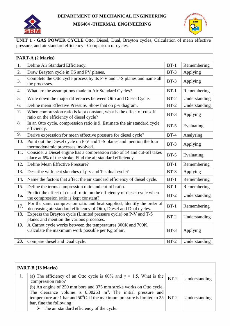
DEPARTMENT OF MECHANICAL ENGINEERING
ME6404 -THERMAL ENGINEERING
UNIT 1 - GAS POWER CYCLE Otto, Diesel, Dual, Brayton cycles, Calculation of mean effective
pressure, and air standard efficiency - Comparison of cycles.
PART-A (2 Marks)
1. Define Air Standard Efficiency. BT-1 Remembering
2. Draw Brayton cycle in TS and PV planes. BT-3 Applying
3. Complete the Otto cycle process by its P-V and T-S planes and name all
the processes. BT-3 Applying
4. What are the assumptions made in Air Standard Cycles? BT-1 Remembering
5. Write down the major differences between Otto and Diesel Cycle. BT-2 Understanding
6. Define mean Effective Pressure. Show that on p-v diagram. BT-2 Understanding
7. When compression ratio is kept constant, what is the effect of cut-off
ratio on the efficiency of diesel cycle? BT-3 Applying
8. In an Otto cycle, compression ratio is 9. Estimate the air standard cycle
efficiency. BT-5 Evaluating
9. Derive expression for mean effective pressure for diesel cycle? BT-4 Analysing
10. Point out the Diesel cycle on P-V and T-S planes and mention the four
thermodynamic processes involved. BT-3 Applying
11. Consider a Diesel engine has a compression ratio of 14 and cut-off takes
place at 6% of the stroke. Find the air standard efficiency. BT-5 Evaluating
12. Define Mean Effective Pressure? BT-1 Remembering
13. Describe with neat sketches of p-v and T-s dual cycle? BT-3 Applying
14. Name the factors that affect the air standard efficiency of diesel cycle. BT-1 Remembering
15. Define the terms compression ratio and cut-off ratio. BT-1 Remembering
16. Predict the effect of cut-off ratio on the efficiency of diesel cycle when
the compression ratio is kept constant? BT-2 Understanding
17. For the same compression ratio and heat supplied, Identify the order of decreasing air standard efficiency of Otto, Diesel and Dual cycles.
BT-1 Remembering
18. Express the Brayton cycle (Limited pressure cycle) on P-V and T-S
planes and mention the various processes. BT-2 Understanding
19. A Carnot cycle works between the temperatures 300K and 700K.
Calculate the maximum work possible per Kg of air.
BT-3 Applying
20. Compare diesel and Dual cycle. BT-2 Understanding
PART-B (13 Marks)
1. (a) The efficiency of an Otto cycle is 60% and γ = 1.5. What is the compression ratio?
BT-2 Understanding
(b) An engine of 250 mm bore and 375 mm stroke works on Otto cycle.
The clearance volume is 0.00263 m3. The initial pressure and
temperature are 1 bar and 500C. if the maximum pressure is limited to 25
bar, fine the following :
The air standard efficiency of the cycle.
BT-2 Understanding

The mean effective pressure for the cycle.
2. The minimum pressure and temperature in an Otto cycle are 100 kPa and
27o C. the amount of heat added to the air per cycle is 1500 kJ/kg.
Determine the pressure and temperatures at all points of the air
standard Otto cycle.
Also calculate the specific work and thermal efficiency of the
cycle for a compression ratio of 8:1.
Take for air: cv = 0.72 kJ/kg K and γ = 1.4
BT-3 Applying
3. In a constant volume Otto cycle the pressure at the end of compression
is 15 times that at the start, the temperature of air at the beginning of
compression is 380 C and maximum temperature attained in the cycle is
19500 C. Analyse :
Compression ratio.
Thermal efficiency of the cycle.
Work done.
Take γ for air = 1.4.
BT-4 Analysing
4. An engine working on Otto cycle has a volume of 0.5 m3, pressure 1 bar
and temperature 270 C at the commencement of compression stroke. At
the end of compression stroke, the pressure is 10 bar. Heat added during
the constant volume process is 200 kJ. Evaluating :
Percentage clearance.
Air standard efficiency.
Mean effective pressure.
Power developed by the engine if the engine runs at 400 rpm, so
that there are 200 complete cycles per minutes.
BT-5 Evaluating
5. Express mean effective pressure of an Otto cycle in terms of compression
ratio. BT-2 Understanding
6. An engine with 200 mm cylinder diameter and 300 mm stroke works on
theoretical Diesel cycle. The initial pressure and temperature of air used
are 1 bar and 270C. The cut-off is 8% of the stroke. Evaluate :
Pressure and temperatures at all salient points.
Theoretical air standard efficiency.
Mean effective pressure.
Power of the engine if the working cycles per minute are 380.
BT-5 Evaluating
7. The swept volume of a diesel engine working on dual is 0.0053 m3 and
clearance volume is 0.00035 m3. The maximum pressure is 65 bars. Fuel
injection ends at 5 percent of the stroke. The temperature and pressure at
the compression are 800 C and 0.9 bar. Evaluate the air standard
efficiency of the cycle. Take γ for air = 1.4.
BT-5 Evaluating
8. The compression ratio for a single–cylinder engine operating on dual
cycle is 9. The maximum pressure in the cylinder is limited to 60 bars.
The pressure and temperature of the air at the beginning of the cycle is 1
bar and 300 C. heat is added during constant pressure process up to 4
percent of the stroke. Assuming the cylinder diameter and stroke length
as 250 and 300 mm respectively, Analyse :
The air standard efficiency of the cycle.
The power developed is the number of working cycles are 3 per
second.
Take for air cv = 0.71 kJ/kg K and cp = 1.0 kJ/kg K.
BT-4 Analysing
9. In an engine working on dual cycle, the temperature and pressure at the
beginning of the cycle are 900 C and 1 bar respectively. The compression BT-5 Evaluating

ratio is 9. The maximum pressure is limited to 68 bars and total heat
supplied per kg of air is 1750 kJ. Determine :
Pressure and temperatures at all salient points
Air standard efficiency and MEP
10. The compression ratio and expansion ratio of an oil engine working on
the dual cycle are 9 and 5 respectively. The initial pressure and
temperature of the air are 1 bar and 300 C. The expansion and
compression follow the law PV1.25 = constant. Determine :
Pressure and temperatures at all salient points
Mean effective pressure of the cycle.
Efficiency of the cycle.
Power of the engine if working cycles per second are 8.
Assume: cylinder bore = 250 mm and stroke length = 400 mm.
BT-1 Remembering
11. (a) A diesel engine has a compression ratio of 15 and heat addition at
constant pressure takes at 6 % of stroke. Find the air standard efficiency
of the engine. Take γ for air as 1.4
BT-2 Understanding
(b)The compression ratio of a Dual cycle is 10. The temperature and
pressure at the beginning of the cycle are 1 bar and 27˚C. The maximum
pressure of the cycle is limited to 70 bar and heat supplied is limited to
675 kJ/kg of air. Find the thermal efficiency of the cycle.
BT-2 Understanding
12. Derive an expression for Air Standard Efficiency and state the
assumption of an Otto Cycle. BT-4 Analysing
13. Air enters the compressor of a gas turbine plant operating on Brayton
cycle at 101.325 kPa, 270C. The pressure ratio in the cycle is 6. Calculate
the maximum temperature in the cycle and the cycle efficiency. Assume
WT = 2.5 WC, where WT and WC are the turbine and the compressor
work respectively. Take γ= 1.4.
BT-3
Applying
14 Consider an air standard cycle in which the air enters the compressor at
1.0 bar and 200 C. the pressure of air leaving the compressor is 3.5 bar
and the temperature at turbine inlet is 6000 C. determine per kg of air:
Heat supplied to air and Heat rejected in the cooler
Work available at the shaft and the Efficiency of the cycle
Temperature of air leaving the turbine. For air γ = 1.4 and cp =
1.005 kJ/kg K.
BT-5 Evaluating
PART-C (15 Marks)
1. An engine working on ideal Otto cycle has temperature and pressure, at
the beginning of isentropic compression as 25˚C and 1.5 bar respectively.
Find the compression ratio, if γ = 1.4 and thermal efficiency of the engine
= 48%. Also find temperature and pressure at the end of compression.
BT-6 Creating
2. A diesel engine operating on the air-standard Diesel cycle has six cylinders
of 100 mm bore and 120 mm stroke. The engine speed is 1800 rpm. At the
beginning of compression the pressure and temperature of air are 1.030bar
and 35˚C. If the clearance volume is 1/8th of the stroke volume, calculate
(i) the pressure and temperature at the salient points of the cycle (ii) the
compression ratio (iii) the efficiency of the cycle and (iv) the power output
if the air is heated to 1500˚C. Assume Cp and Cv of air to be 1.004 and
0.717 kJ / kg K respectively.
BT-2 Understanding
3. For an engine working on the ideal Dual cycle, the compression ratio is 10
and the maximum pressure is limited to 70 bar. If the heat supplied is 1680
kJ/kg, find the pressure and temperatures at the various salient points of
BT-4 Analysing

the cycle and the cycle efficiency. The pressure and temperature of air at
the commencement of compression are 1 bar and 100˚C respectively.
Assume Cp=1.004 kJ/kg K and Cv= 0.717 kJ/kg K for air.
4. The compression ratio of an engine is 10 and the temperature and pressure
at the start of compression is 37˚C and 1 bar. The compression and
expansion processes are both isentropic and the heat is rejected at exhaust
at constant volume. The amount of heat added during the cycle is 2730
kJ/kg. Determine the mean effective pressure and thermal efficiency of the
cycle if (i) the maximum pressure is limited to 70 bar and heat is added at
both constant volume and constant pressure and (ii) if all the heat is added
at constant volume. In this case how much additional work per kg of
charge would be obtained if it were possible to expand isentropically the
exhaust gases to their original pressure of 1 bar? Assume that the charge
has the same physical properties as that of air.
BT-5 Evaluating
UNIT II INTERNAL COMBUSTION ENGINES Classification - Components and their function. Valve
timing diagram and port timing diagram – actual and theoretical p-V diagram of four stroke and two stroke
engines. Simple and complete Carburetor. MPFI, Diesel pump and injector system. Battery and Magneto Ignition
System - Principles of Combustion and knocking in SI and CI Engines. Lubrication and Cooling systems.
Performance Calculation.
PART-A (2 Marks)
1. What are the advantages in MPFI System? BT-1 Remembering
2. What is Octane number in I.C. Engine? BT-1 Remembering
3. What is the antifreeze solutions used in water cooling systems? BT-1 Remembering
4. What is meant by motoring test? BT-1 Remembering
5. Show the valve overlapping period of a typical 4-stroke petrol engine
on valve timing diagram. BT-3 Applying
6. Define the phenomenon Knocking in spark ignited engines. BT-2 Understanding
7. Write the important requirement of fuel injection system. BT-2 Understanding
8. State the purpose of thermostat in an engine cooling system. BT-2 Understanding
9. What are the function of a flywheel? BT-1 Remembering
10. What are the advantages of four stroke cycle engine over two stroke
cycle engines BT-1 Remembering
11. What is a carburettor? State any two functions of carburettor. BT-4 Analysing
12. What is a unit Injection System? BT-1 Remembering
13. List the four stages of combustion in CI engine. BT-3 Applying
14. Draw the theoretical P-V diagram for four stroke engines. BT-6 Creating
15. Draw the theoretical P-V diagram for two stroke engines BT-6 Creating
16. Draw the actual P-V diagram for four stroke engines. BT-2 Understanding
17. Draw the actual P-V diagram for two stroke engines BT-2 Understanding
18. Define the term Brake Power. BT-1 Remembering
19. What are the advantages of four stroke cycle engines over two stroke
engines? BT-5 Evaluating
20. Analyse the cause for ignition delay? BT-4 Analysing

PART-B (13 Marks)
1. Explain the typical Port timing diagram and the significance of each
angle in the Port timing diagram in Two Stroke Engine BT-5 Evaluating
2. Describe with suitable sketches the following system of a modern
carburettor.
(i) Main Metering System
(ii) Idling System
(iii) Economizer System
(iv) Acceleration Pump System
(v) Choke
BT-1 Remembering
3. Discuss the difference between theoretical and actual valve timing
diagram of a diesel engine. BT-1 Remembering
4. Explain the working principle of diesel injector with a neat diagram. BT-2 Understanding
5. (a) Explain the phenomena of knocking in diesel engines. BT-2 Understanding
(b) What are the different factors which influence the knocking? BT-2 Understanding
6. Analyse the effect of Octane and Cetane number on the I.C. Engine Cycle
and performance BT-6 Creating
7. (a) Explain with neat sketch the working principle of Battery ignition System. BT-1 Remembering
(b) Explain with neat sketch the working principle of Magneto ignition System. BT-1 Remembering
8. a. Explain any one lubrication system with a neat sketch. BT-2 Understanding b. Explain the Bosch fuel Injector with neat sketch. BT-2 Understanding
9. A four stroke four cylinder gasoline engine has a bore of 60 mm and a
stroke of 100 mm. On test it develops a torque of 66.5 N-m when running
at 3000 rpm. If the clearance volume in each cylinder is 60 cc the relative
efficiency with respect to the BTE is 0.5 and the CV of the fuel is
42MJ/kg, determine the fuel consumption in kg/h and the BMEP.
BT-5 Evaluating
10. Following data relate to 4-cylinder four stroke petrol engine. Air fuel
ratio by weight = 16: 1, calorific value of the fuel = 45200 kJ/kg,
mechanical efficiency = 82%, air-standard efficiency = 52%, relative
efficiency = 70%, volumetric efficiency = 78 %, stroke/bore ratio = 1.25,
suction conditions = 1 bar & 25oC, r.p.m. = 2400 and power at brakes
=72kW. Evaluating: (1) Compression ratio, (2) Indicated thermal
efficiency, (3) Brake specific fuel consumption, (4) Bore and Stroke.
BT-5 Evaluating
11. Air consumption for a four-stroke petrol engine is measured by means of
a circular orifice of diameter 3.2 cm. The co-efficient of discharge for
the orifice is 0.62 and the pressure across the orifice is 150 mm of water.
The barometer reads 760 mm of Hg. Temperature of air in the room is
20oC. The piston displacement volume is 0.00178 m3. The compression
ratio is 6.5. The fuel consumption is 0.135 kg/min of calorific value
43900 kJ/kg. The brake power developed at 2500 r.p.m. is 28 kW.
Determine: (1) The volumetric efficiency on the basic of air alone. (2)
The air-fuel ratio. (3) The brake mean effective pressure. (4) The relative
efficiency on the brake thermal efficiency on the brake thermal
efficiency basis.
BT-5 Evaluating
12. (a) Explain Normal and abnormal Combustion in SI engines. BT-4 Analysing
b. What are the factors affecting he flame speed of the engine. BT-4 Analysing
13. Write a note on Cooling system for an I.C. Engine in detail with relevant
sketches of various types. BT-2 Understanding
14. a. Explain four stages of combustion in CI engines. BT-2 Understanding
b. What are the factors affecting Ignition Delay and Delay Period? BT-1 Remembering

PART-C (15 Marks)
1. Explain knocking in CI engines. Draw the Time vs Pressure curve from
SI Engine and SI engine. BT-2 Understanding
2. Explain with neat sketch the splash and wet sump lubrication system.
What are the advantages of wet sump lubrication system? BT-2 Understanding
3. Following data are available for a four stroke petrol engine:
Air fuel ratio (by weight) 15:5:1
Calorific value of the fuel 45000 kJ/kg
Mechanical efficiency 80%
Air standard efficiency 53%
Relative efficiency based on
Indicated thermal efficiency 70%
Volumetric efficiency 80%
Stroke/Bore ratio 1.25
Suction conditions 1 bar, 270C
Speed 2400 RPM
Power at brakes 75 kW
Calculate:
Compression ratio
Indicated thermal efficiency
Brake specific fuel consumption
Bore and stroke.
BT-4 Analysing
4. The following data refer to an oil engine working on Otto four-stroke
cycle:
Brake power =14.7 kW
Suction pressure =0.9 bar
Mechanical efficiency =80%
Ratio of compression =5
Index of compression curve =1.35
Index of expansion curve =1.3
Maximum explosion pressure =24 bar
Engine speed =1000 RPM
Ratio of stroke: bore =1.5
Find the diameter and stroke of the piston.
BT-6 Creating
UNIT III- STEAM NOZZLES AND TURBINES : Flow of steam through nozzles, shapes of nozzles, effect of friction, critical pressure ratio, Supersaturated flow.
Impulse and Reaction principles, compounding, velocity diagram for simple and multi-stage turbines speed
regulations –Governors.
PART-A (2 Marks)
1. Define Critical Pressure Ratio in steam flow through Nozzles? BT - 1 Remembering
2. If the enthalpy drop in a steam nozzle of efficiency 92% is 100 kJ/kg
determine the exit velocity of steam. BT - 5 Evaluating
3. Define stage efficiency. BT - 1 Remembering
4. What is the effect of super saturation in the nozzles? BT - 2 Understanding
5. Draw the Shape of Supersonic Nozzle. BT - 3 Applying
6. Distinguish between impulse and reaction principle. BT - 2 Understanding
7. Express the effects of friction on the flow through a steam nozzle? BT - 3 Applying
8. Discuss the importance of compounding of steam turbine? BT - 1 Remembering

9. What is meant by Pressure Compounding? BT - 2 Understanding
10. Explain supersaturated flow? BT - 3 Applying
11. Name the various types of nozzles and their function? BT - 2 Understanding
12. Summarize the different losses involved in steam turbines? BT - 1 Remembering
13. Define Diagram efficiency. BT - 5 Evaluating
14. Explain ‘Degree of Reaction’ in a steam turbine. BT - 4 Analysing
15. Analyze the effects of super saturation in a nozzle? BT - 6 Creating
16. Define nozzle efficiency. BT - 3 Applying
17. Where is nozzle control governing is used? BT - 1 Remembering
18. Show and explain the principles of impulse and reaction turbines? BT - 2 Understanding
19. If the enthalpy drop in a steam nozzle of efficiency 88% is 95 kJ/kg
determine the exit velocity of steam. BT - 5 Evaluating
20. Define blade velocity co-efficient? BT - 1 Remembering
PART-B (13 Marks)
1. (a) Mention the types of nozzles you know, Where are these used? BT - 1 Remembering
(b) Steam having pressure of 10.5 bar and 0.95 dryness is expanded
through a convergent-divergent nozzle and the pressure of steam
leaving the nozzle is 0.85 bar. Find the velocity at the throat for
maximum discharge conditions. Index of expansion may be assumed
as 1.135. Calculate mass rate of flow of steam through the nozzle.
BT - 2 Understanding
2. (a)Dry saturated steam enters a frictionless adiabatic nozzle with
negligible velocity at a temperature of 300oC. It is expanded to pressure
of 5000 kPa. The mass flow rate is 1 kg/s. Calculate the exit velocity
of the steam.
BT - 2 Understanding
(b)Steam is expanded in a set of nozzles from 10 bar and 200oC to 5
bar. What type of Nozzle is it? Neglecting the initial velocity find
minimum area of the nozzle required to allow a flow of 3 kg/s under
the given conditions. Assume that expansion of steam to be isentropic.
BT-3 Applying
3. In a steam nozzle, the steam expands from 4 bar to 1 bar. The initial
velocity is 60 m/s and the initial temperature is 200oC. Determine the
exit velocity if the nozzle efficiency is 92%.
BT-3 Applying
4. Describe (Derive) the expression for critical pressure ratio in terms of
index of expansion. BT - 1 Remembering
5. Dry saturated steam enters a steam nozzle at a pressure of 15 bar and
is discharged at a pressure of 2 bar. If the dryness fraction of discharge
steam is 0.96, what will be the final velocity of steam? Neglect initial
velocity of steam. If 10% of heat drop is lost in friction, Examine (find)
the percentage reduction in the final velocity.
BT - 5 Evaluating
6. Dry saturated steam at a pressure of 11 bar enters a convergent-
divergent nozzle and leaves at a pressure of 2 bar. If the flow is
adiabatic and frictionless, determine: (i) The exit velocity of steam. (ii)
Ratio of cross section at exit and that at throat.
Assume the index of adiabatic expansion to be 1.135.
BT - 6 Creating
7. The nozzles of De-Laval stream turbine are supplied with dry saturated
steam at a pressure of 9 bar. The pressure at the outlet is 1 bar. The
turbine has two nozzles with a throat diameter of 2.5 mm. Assuming
BT - 3 Applying

nozzle efficiency as 90% and that of turbine rotor 35%, find the quality
of steam used per hour and the power developed.
8. Explain with a neat sketch of velocity compounding, pressure
compounding, pressure-velocity compounding. BT-3 Applying
9. A 50 % reaction turbine (with symmetrical velocity triangles) running
at 400 rpm has the exit angle of the blades as 20° C and the velocity of
steam relative to the blades at the exit is 1.35 times the mean speed of
the blade. The steam flow rate is 8.33 Kg/s and at a particular stage the
specific volume is 1.381 m3/Kg. Evaluate for this stage. (i) A suitable
blade height, assuming the rotor mean diameter 12 times the blade
height, and (ii) The diagram work
BT - 5 Evaluating
10. A single row impulse turbine develops 132.4 kW at a blade speed of
175 m/s, using 2 kg of steam per sec. Steam leaves the nozzle at 400
m/s. Velocity coefficient of the blades is 0.9. Steam leaves the turbine
blades axially. Calculate nozzle angle, blade angles at entry and exit,
assuming no shock.
BT - 3 Applying
11. A single-stage impulse turbine is supplied steam at 5 bar and 200°C at
the rate of 50 kg/min and it expands into a condenser at a pressure of
0.2 bar. The blade speed is 400 m/s and nozzles are inclined at 20°C to
the plane of the wheel. The blade angle at the exit of the moving blade
is 30°C. Neglecting friction losses in the moving blade, Evaluate (i)
Velocity of the steam entering the blades (ii) Power developed, (iii).
Blade efficiency and (iv) Stage efficiency.
BT - 5 Evaluating
12.
In a stage of impulse reaction turbine operating with 50% degree of
reaction, the blades are identical in shape. The outlet angle of the
moving blades in 19o and the absolute discharge velocity of steam is
100 m/s in the direction 70o to the motion of the blades. If the rate of
flow through the turbine is 15000 kg/hr., calculate the power
developed by the turbine.
BT - 3 Applying
13.
A stage of a steam turbine is supplied with steam at a pressure of 50
bar and 350oC, and exhausts at a pressure of 5 bar. The isentropic
efficiency of the stage is 0.82 and the steam consumption is 2270
kg/min. Determine the power of the stage.
BT - 3 Applying
14.
The velocity of steam exiting the nozzle of the impulse stage of a
turbine is 400 m/s. The blades operate close to maximum blading
efficiency. The nozzle angle is 20o. Considering equiangular blades
and neglecting blade friction, calculate for a steam flow of 0.6 kg/s, the
diagram power and the diagram efficiency.
BT - 3 Applying
PART-C (15 Marks)
1. A convergent-Divergent nozzle is required to discharge 2kg of steam
per second. The nozzle is supplied with steam at 6.9 bar and180oC and
discharge takes place against a back pressure of 0.98 bar. Expansion
up to throat is isentropic and the frictional resistance between the throat
and exit is equivalent to 62.76 kJ/kg of steam. Taking approach
velocity of 75 m/s and throat pressure 3.9 bar, estimate:
Suitable areas for the throat and Exit
Overall efficiency of the nozzle based on the enthalpy drop
between the actual inlet pressure, and temperature and the exit
pressure.
BT - 6 Creating
2. (a) Define Critical pressure ratio of nozzle and discuss why attainment of sonic velocity determines the maximum mass rate of flow through steam nozzle.
BT - 3 Applying
(b) Explain the metastable expansion of steam in a nozzle with help of h-s diagram.
BT - 1 Remembering
3. A simple impulse turbine has one ring of moving blades running at 150
m/s. the absolute velocity of steam at exit from the stage is 85 m/s at
an angle of 80o from the tangential direction. Blade velocity co-
efficient is 0.82 and the rate of steam flowing through the stage is 2.5
kg/s. if the blades are equiangular, determine:
Blade angles
Nozzle angle
Absolute velocity of the steam issuing from the nozzle
Axial thrust.
BT - 6 Creating
4. In a De-Laval turbine steam issues from the nozzle with a velocity of
1200 m/s. The nozzle angle is 20o, the mean blade velocity is 400 m/s,
the inlet and outlet angles of blades are equal. The mass of steam
flowing through the turbine per hour is 1000 kg. Calculate:
Blade angles,
Relative velocity of steam entering the blades,
Tangential force on the blades,
Power developed
Blade efficiency
Take blade velocity co-efficient as 0.8.
BT - 6 Creating
UNIT IV AIR COMPRESSOR:Classification and working principle of various types of compressors, work of
compression with and without clearance, Volumetric efficiency, Isothermal efficiency and Isentropic efficiency of
reciprocating compressors, Multistage air compressor and inter cooling –work of multistage air compressor
PART-A (2 Marks)
1. Generalize the role of intercooler used to reduce the power
consumption of compressor? BT - 6 Creating
2. List the advantage of multistage compressor over single stage
compressor. BT – 1 Remembering
3. Explain volumetric efficiency of a compressor. BT – 4 Analysing
4. Select the main advantage of inter cooling in multi-stage reciprocating
compressors? BT – 4 Analysing
5. Give two examples for positive displacement and rotary compressors. BT – 2 Understanding
6. Evaluate the necessity of clearance in reciprocating compressors? BT – 5 Evaluating
7. Differentiate positive and non-positive displacement compressors. BT – 4 Analysing
8. What do you mean by perfect intercooling? BT – 6 Creating
9. Explain the terms applied to air compressor: Volumetric efficiency and
Isothermal efficiency. BT – 5 Evaluating
10. Give two merits of rotary compressor over reciprocating compressor. BT – 2 Understanding
11. Name the compression process in which work done is minimum in
reciprocating air compressor. BT – 1 Remembering
12. Express the P - v diagram of a two stage reciprocating air compressor. BT - 2 Understanding

13. Classify the advantages of multistage compression with inter cooling over single stage compression for the same pressure ratio?
BT – 3 Applying
14. Define the terms as applied to reciprocating compressor: Mechanical
efficiency and isentropic efficiency. BT – 1 Remembering
15. Describe the term ‘Define free air delivery’. BT – 1 Remembering
16. Examine the effect of clearance volume in reciprocating air
compressor? BT – 3 Applying
17. Classify the various types of air-compressors. BT – 3 Applying
18. If C is the clearance ratio for a reciprocation air compressor what will
be the volumetric efficiency? BT – 6 Creating
19. Give the expression for work done for a two-stage compression with
prefect intercooling. BT – 2 Understanding
20. Define the mechanical efficiency of a reciprocating air compressor. BT - 1 Remembering
PART-B (13 Marks)
1. A single stage single acting reciprocating air compressor delivers 15m3 of free air per minute from 1 bar to 8 bars. The speed of compressor is 300 rpm. Assuming that compression and expansion follow the law pv1.35 = constant and clearance is 1/16th of the swept volume, Estimate (find) the diameter and stroke of the compressor. Take stroke length is 1.5 times the bore diameter. The temperature and pressure of air at the suction are same as atm air.
BT - 2 Understanding
2. Consider a single acting two stage reciprocating air compressor running
at 300 rpm. Air is compressed at a rate of 4.5Kg/min from 1.013 bar and
288 K through a pressure ratio of 9 to 1. Both the stages have same
pressure ratio and the index of expansion in both stages is Assume a
complete inter-cooling, Identify (find) the indicated power and the
cylinder swept volume required. Assume that the clearance volumes of
both stages are 5% of their respective swept volumes.
BT - 1 Remembering
3. A two stage air compressor compresses air from 1 bar and 20°C to 42
bar. If the law of compression is pv1.3 = constant and the inter cooling
is perfect. Examine (find) per kg of air (i) The work done in
compression and (ii) The mass of cooling water necessary for
abstracting the heat in the intercooler, if the temperature rise of the
cooling water is 25°C.
BT - 1 Remembering
4. Express a neat sketch describe any one type of rotary compressor. BT - 6 Creating
5. A single acting single stage compressor is belt driven from an electric
motor at 400 rpm. The cylinder diameter is 15 cm and the stroke is 17.5
cm. The air is compressed from 1 bar to 7 bar and the law of
compression PV1.3 = constant. Predict (find) the power of the motor, if
transmission efficiency is 97 % and the mechanical efficiency of the
compressor is 90%. Neglect clearance effects.
BT - 2 Understanding
6. A three-stage air-compressor delivers 5.2 m3 of free air per minute. The
suction pressure and temperature are 1 bar and 30°C. The ambient
pressure and temperature are 1.03 bar and 20°C. The air is cooled to
30°C after each stage of compression. The delivery pressure of the
compressor is 150 bar. The RPM of the compressor is 300. The
clearances of LP, I.P and H.P cylinders are 5% of the respective strokes.
BT-3 Applying

The index of compression and re expansion in all stages is 1.35.
Neglecting pressure losses, Calculate the B.P of the motor required to
run the compressor if the mechanical efficiency is 80%.
7. Derive the expression for volumetric efficiency of a reciprocating air
compressor and explain why it is less than unity.
BT - 4 Analysing
8. Analyze (determine) the size of the cylinder of a double acting air
compressor of 32 KW I.P, in which air is drawn in at 1 bar and
compressed to 16 bar according to the law pv 1.25 = constant. R.P.M.
300, Piston speed = 180 m/min, Volumetric efficiency = 0.8.
BT - 4 Analysing
9. A two-stage double acting air compressor, operating at 200 r.p.m, takes
in air at 1.013 bar and 27° C. The size of the L.P. cylinder is 356 x 375
mm, the stroke of H.P. cylinder is the same as that of the L.P. cylinder
and the clearance of both the cylinders is 4%. The air passes through the
intercooler so that it enters HP cylinder at 27C and 3.850 bar, finally it
is discharged from the compressor at 15.4bar. The values of n for both
cylinders are 1.25. Cp=1.0035kJ/kgK. And R=0.28kJ/kgK. Calculate: i.
The heat rejected in the intercooler. ii. The diameter of HP cylinder and
iii. The power required to drive HP cylinder.
BT - 1 Remembering
10. Explain the construction and working of Multi stage compressor and discuss the perfect and imperfect inter cooling with neat a sketch. And drive minimum work required for a two stage reciprocating air compressor.
BT - 4 Analysing
11. A single stage single acting reciprocating air compressor takes in 17
m3/min at suction conditions of 100 kPa and 25°C. The delivery
pressure is 700 kPa. The clearance volume is 6% of swept volume. The
compression and expansion follows the law pV1.3 = Constant. The speed
of the compressor is 600 rpm. Stroke to bore ratio is 1. Invent (find) the
power required to drive the compressor and Cylinder dimensions.
BT - 6 Creating
12. Drive the work done for a single stage air compressor with and without
clearance volume. BT - 5 Evaluating
13. Discuss with suitable sketches the working of two stage air compressor
with actual p-v Diagram.
BT - 4 Analysing
14. A multi stage air compressor is to be designed to evaluate the pressure
from 1 bar to 120 bars. Such that the single stage pressure ratio not to
exceed 4. Examine (find) (i) Number of stages, exact stage pressure
ratio (iii) Inter stage pressure.
BT - 4 Analysing
PART-C (15 Marks)
1. A two cylinder single acting air compressor is to deliver 16kg of air per
minute at 7 bar form suction conditions 1 bar and 15oC. The clearance
may be taken as 4% of stroke volume and the index for both compression
and re-expansion as 1.3. The compressor is directly coupled to a four
cylinder four stroke petrol engine which runs at 2000rpm with a brake
mean effective pressure of 5.5bar. Assuming a stroke-bore ration of 1.2
for both engine and compressor and a mechanical efficiency of 82% for
compressor, calculate the required cylinder dimensions.
BT - 5 Evaluating
2. A single stage reciprocating air compressor has clearance volume 5% of
stroke volume of 0.05m3/s. The intake conditions are 95kN/m2 and 300K.
The delivery pressure is 720kN/m2.Determine the volumetric efficiency
referred to i. intake conditions ii. Atmospheric conditions of 100kN/m2
and 290K iii. FAD and iv. Power required to drive the compressor, if the
ratio of actual power to indicated power is 1.5. Take the index of
compression and expansion as 1.3.
BT - 6 Creating
3. A single cylinder single acting air compressor compresses 30m3 of air at
a pressure of 1bar and 27oC to 700kPa. Calculate the power required for
the compressor, if the compression is i. isothermal, ii. Polytropic, iii.
Adiabatic. Take n=1.25.
BT - 5 Evaluating
4. A single acting tow stage-reciprocating compressor with complete inter
cooling takes in air at the rate of 0.5m3/s. The intake pressure and
temperature of air are 1 bar and 23oC. The air is compressed to a final
pressure of 8bar. Estimate i. the intermediate pressure ii. Total volume of
each cylinder, iii. The rate of heat rejection on the inter cooling. Assume
compression follows the law pV1.35=C and compressor runs at 650rpm.
BT - 4 Analysing
UNIT-V REFRIGERATION AND AIR COMDITIONING:Refrigerants - Vapor compression refrigeration cycle-
super heat, sub cooling – Performance calculations - working principle of vapor absorption system, Ammonia –Water,
Lithium bromide – water systems (Description only) . Air conditioning system - Processes, Types and Working Principles.
- Concept of RSHF, GSHF, ESHF- Cooling Load calculations.
PART-A (2 Marks)
1. Define dew point temperature. BT - 1 Remembering
2. Explain adiabatic humidification of air. BT -4 Analysing
3. Describe: ‘Ton of refrigeration’. BT - 1 Remembering
4. List out the properties of an ideal refrigerant? BT - 1 Remembering
5. Define the terms RSHF and GSHF. BT - 1 Remembering
6. Explain ‘wet bulb depression’. BT - 4 Analysing
7. What is COP of refrigerators? BT - 6 Creating
8. Prepare the list of expansion devices used in a vapor compression plant? BT - 6 Creating
9. What is sensible heating or cooling? BT - 6 Creating
10. How are air-conditioning systems classified? BT - 2 Understanding
11. Evaluate the effect of inter-commercial Non-CFC refrigerants? BT - 5 Evaluating
12. What is the function of throttling valve? BT - 6 Creating
13. Analyse the effects of superheat and sub cooling in vapour compression
cycle? BT- 4 Analysing
14. Name the various components used in simple vapour absorption system. BT -1 Remembering
15. Define sensible heat ratio and draw cooling and dehumidification in a
typical psychrometric chart. BT - 1 Remembering
16. Identify the important components used in winter air conditioning system? BT- 1 Remembering
17. What is net refrigerating effect of a refrigerant? BT -6 Creating
18. Prepare the difference of actual vapor compression cycle from that of the
ideal cycle? BT - 6 Creating
19. What do you mean by the term "Infiltration" in heat load calculation? BT-2 Understanding
20. What are the various sources of heat gain of an air-conditioned space? BT-1 Remembering
PART-B (13 Marks)
1. Explain the construction and working of vapour absorption refrigeration system.
BT - 2 Understanding
2. With a neat sketch, explain a vapour compression refrigeration system.
BT - 5 Evaluating
3. A refrigeration system of 10.5 tones capacity at an evaporator temperature
of -12°C and a condenser temperature of 27°C is needed in a food storage
locker. The refrigerant ammonia is sub cooled by 6°C before entering the
expansion valve. The vapour is 0.95 dry as it leaves the evaporator coil.
The compression in the compressor is of adiabatic type. Examine (find), (i)
Condition of vapour at the outlet of the compressor (ii) Condition of vapour
at the entrance of the evaporator (iii) COP and (v) The power required.
Neglect valve throttling and clearance effect.
BT - 1 Remembering
4. A Freon-12 refrigerator producing a cooling effect of 20 kJ/s operates on
a simple vapour compression cycle with pressure limits of 1.509 bar and
9.607 bar. The vapour leaves the evaporator dry saturated and there is no
under cooling. Examine (determine) the power required by the machine.
BT - 1 Remembering
5. If the compressor operates at 300 r.p.m. and has a clearance volume of 3%
of stroke volume, Examine (determine) the piston displacement of the
compressor. For compressor assume that the expansion following the law
pv1.3 = constant.
BT - 1 Remembering
6. A simple saturation refrigeration cycle developing 15 tons of refrigeration
using R12 operates with a condensing temperature of 35°C and an
evaporator temperature of - 6°C. Examine (calculate): (i) The refrigerating
BT-3 Applying
effect, (ii) Refrigerant flow rate, (iii). The power required to drive the
compressor, (iv) COP.
7. a. Explain with a neat sketch the summer Air - Conditioning suitable for
Chennai weather Conditions BT - 4 Analysing
b. Prepare a neat layout of summer Air Conditioner BT - 6 Creating
8. Explain the summer Air Conditioning system suitable for hot and humid
weather.
BT - 4 Analyzing
9. For a summer air conditioning installation for industrial application the following data is given:
Room Design : 50%RH and 26oC DBT Outside air :40oC DBT and 10%RH Room sensible heat gain :40kW Room latent heat loss :10kW
50% of return air form the room is mixed with outdoor air and pre cooled sensibly in a cooling coil to 28C before being passed through adiabatic washer. Determine:
i. Supply air conditions to the space ii. Quantity of fresh outside air iii. Refrigerating capacity of the pre cooler coil.
Humidifying efficiency of the adiabatic washer or evaporator cooler and entering and leaving conditions at the washer.
BT - 1 Remembering
10. Prepare and Express various processes of summer Air Conditioning in a Psychometric chart
BT - 4 Analysing
11. A sling psychrometer reads 40OC DBT and 36OC WBT. Estimate the
humidity ratio, relative humidity, DPT, specific volume of air, density of
air, density of water vapour and enthalpy.
BT - 6 Creating
12. Saturated air at 21˚C is passed through a drier so that the final relative
humidity is 20%. The air is then passed through a cooler until its final
temperature is 21˚C without a change in specific humidity. Estimate (i) The
temperature of air after drying process, (ii) the heat rejected in cooling
process, (iii) the dew point temperature at the end of drying process.
BT - 5 Evaluating
13. 40 m3 of air per minute at 31˚C DBT and 18.5˚C WBT is passed over the
cooling coil whose surface temperature is 4.4˚C. The coil cooling capacity
is 3.56 tons of refrigeration under the given condition of air. Estimate DBT
and WBT of the air leaving the cooling coil.
BT - 4 Analysing
14. A sling psychrometer in a laboratory test recorded the following readings. Dry bulb temperature = 35°C, Wet bulb temperature = 25°C. Calculate the following
(i) Specific humidity (ii) Relative humidity (iii) Vapour density in air (iv) Dew point temperature and (v) Enthalpy of mixture per kg of dry air
Take atmospheric pressure = 1.0132 bar.
BT - 4 Analysing

PART-C (15 Marks)
1. A CO2 refrigeration system works between 56.25 bar and 21.2 bar. The refrigerant leaves the compressor at32oC with total heat 246.2kJ/kg. Determine the theoretical co-efficient of performance of the plant. The properties of CO2 are
Pressure in bar
Sat. Temp
Enthalpy kJ/kg Entropy kJ/kg
Liquid Vapour Liquid Vapour
56.25 18.5 52.75 214.37 0.167 0.7244
21.2 -18 -37.68 234.9 -0.150 0.9170
BT - 6 Creating
2. An ammonia refrigerator produces 20 tons of ice per day from and at 0oC. The condensation and evaporation takes at 20oCand -20oC respectively. The temperature of the vapour at the end of isentropic compression is 50 oC and there is no under cooling of the liquid. The actual COP is 70% of the theoretical COP. Determine i. The rate of NH3 circulation and ii. The size of single acting compressor when running at 240rpm assuming L=D and volumetric efficiency of 80%. Take latent heat of ice is 335kJ/kg, specific heat of superheat vapour is 2.8kJ/kg-K and specific volume of saturated vapour at -20oC is 0.62m3/kg. Use the following properties of ammonia:
Sat.Temp oC
Enthalpy kJ/kg Entropy kJ/kg
hf hg sf sg
20 274.98 1461.58 1.0434 5.0919
-20 89.72 1419.05 0.3682 5.6204
BT - 6 Creating
3. An office is to be air-conditioned for 50 staff when the outdoor conditions are 30°C DBT and 75% RH if the quantity of air supplied is 0.4m3/min/person, Analyse (Calculate) the following:
i. Capacity of the cooling coil in tones of refrigeration ii. Capacity of the heating coil in kW.
iii. Amount of water vapour removed per hour. Assume that
required air inlet conditions are 20°C DBT and 60% RH, Air is
conditioned first by cooling and dehumidifying and then by heating.
(iv). If the heating coil surface temperature is 25°C, find the by-pass
factor of the heating coil?
BT - 5 Evaluating
4. A restaurant with a capacity of 100 persons is to be air-conditioned with the following conditions:
Outside conditions=30oC,70%RH Desired inside conditions=23oC,55%RH Quantity of air supplied=05m3/min/person The desired conditions are achieved by cooling, dehumidifying and then heating. Determine: 1. Capacity of cooling coils in tones of refrigeration. 2. Capacity of heating coil and 3. Amount of water removed by dehumidifier.
BT - 4 Analysing