Embed Size (px)
Citation preview
o
o
ENGINEERING REPORT
KEONEPOKO - NUl "2 PRODUCTION WELL
AND SUPPORTING FACILITIES
PAHOA, PUNA, HAWAII
Prepared for:
Department of Hawaiian Home Lands State of Hawaii
Prepared by:
Engineers Surveyors Hawaii, Inc. 1020 Auahi Street
Suite No.1," Building No.6 Honolulu, Hawaii 96814
April, 1998
o TABLE OF CONTENTS
I. GENERAL INFORMATION
A. Purpose of Report B. Description of Water System C. Name of Owners and Authorized Representatives
ll. PHYSICAL AND HYDROLOGICAL CHARACTERISTICS OF THE PROJECT SITE
A. Location B. Physical Dimensions of the 'Well C. Climate D. Topography and Site Description E. Geology and Foundation Conditions F. Earthquake Considerations and Design Parameters G. Groundwater Conditions H. Flood Conditions I. Conformance with Land Use: and Zoning Regulations J. Water Development and Future Use
Ill. EXTENT OF WATERWORKS SYSTEM
A. Description of Existing Systc::ms and Future Service B. Description of System Population and Consumption C. Appraisal of Future Requirements of System D. Provisions for System Extension/Expansion E. Fire Protection and Pressure Capacities F. Alternate Solutions/Supporting Data for System G. Archaeology and Historic Sites H. Environmental and Economic Impact
IV. POTENTIAL SOURCES OF CONTAMINATION
A. Description of Well Site B. Orientation Maps C. Water Quality and Contamination Analysis D. Hazardous Materials E. Land Use Classification
V. SOURCES OF WATER SUPPLY
i

0
o
VI. PROPOSED TREATMENT WORKS
VII. PUMPING FACILITIES
VIII. FINISHED WATER STORAGE
IX. WATER DISTRIBUTION SYSTEM
X. FINANCING
XI. PROFESSIONAL ENGINEER CERTIFICATION
XII. REFERENCES
EXHIBITS
A. Vicinity Map
B. Location Map
C. Keaau-Pahoa Extension (12" Trunkline)
D. Tax Map Key for Keonepoko-Nui Well and Reservoir Site
E. Projected Water Demand
F. Plan Showing Existing Drywells and Individual Wastewater Systems in Relation to Water Wells
APPENDIX
A. WELL COMPLETION REPORT - KEONEPOKO NUl 2 WELL (3188-02)
B. RESULTS OF DRILLING AND TESTING
c. "HYDROLOGIC FEASffiILITY OF ADDITIONAL WELL SOURCE AT KEONEPOKO RESERVOIR SITE (DWS), HHL MAKUU FARM LOTS, PAHOA, PUNA, HAWAII," BY WATER RESOURCE ASSOCIATES
11
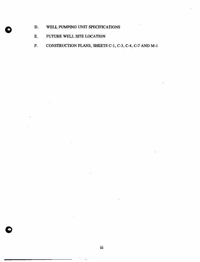
o D. WELL PUMPING UNIT SPECIFICATIONS
E. FUTURE WELL SITE LOCATION
F. CONSTRUCTION PLANS, SHEETS C-l,C-3, C-4, C-7 AND M-l
iii
o I.
o
GENERAL INFORMATION
A. PURPOSE OF REPORT
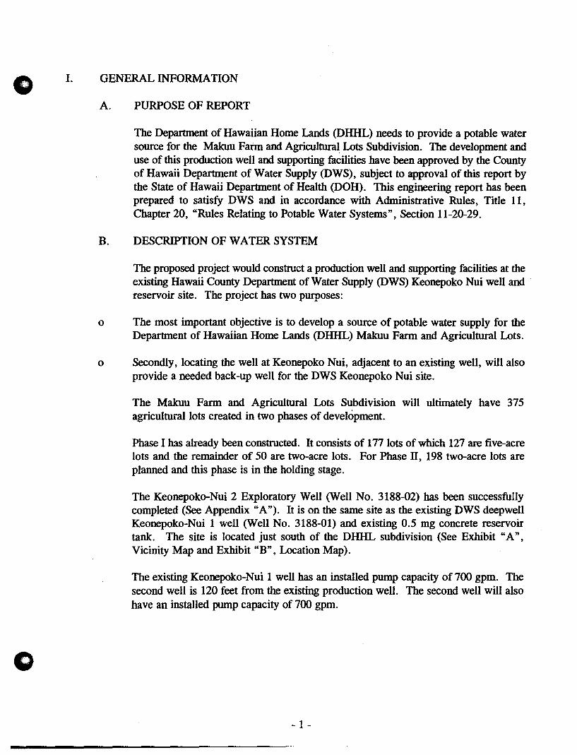
The Department of Hawaiian Home Lands (DHHL) needs to provide a potable water source for the Makuu Farm and Agricultural Lots Subdivision. The development and use of this production well and supporting facilities have been approved by the County of Hawaii Department of Water Supply (DWS), subject to approval of this report by the State of Hawaii Department of Health (DOH). This engineering report has been prepared to satisfy DWS and in accordance with Administrative Rules, Title 11, Chapter 20, "Rules Relating to Potable Water Systems", Section 11-20-29.
B. DESCRIPTION OF WATER SYSTEM
The proposed project would construct a production well and supporting facilities at the existing Hawaii County Department of Water Supply (DWS) Keonepoko Nui well and reservoir site. The project has two purposes:
o The most important objective is to develop a source of potable water supply for the Department of Hawaiian Home Lands (DHHL) Makuu Farm and Agricultural Lots.
o Secondly, locating the well at Keonepoko Nui, adjacent to an existing well, will also provide a needed back-up well for the DWS Keonepoko Nui site.
The Makuu Farm and Agricultural Lots Subdivision will ultimately have 375 agricultural lots created in two phases of development.
Phase I has already been constructed. It consists of 177 lots of which 127 are five-acre lots and the remainder of 50 are two-acre lots. For Phase II, 198 two-acre lots are planned and this phase is in the holding stage.
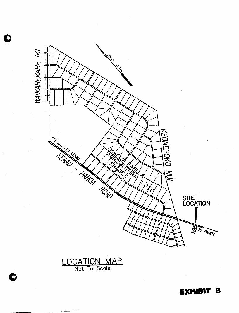
The Keonepoko-Nui 2 Exploratory Well (Well No. 3188-02) has been successfully completed (See Appendix "A"). It is on the same site as the existing DWS deepwell Keonepoko-Nui 1 well (Well No. 3188-01) and existing 0.5 mg concrete reservoir tank. The site is located just south of the DHHL subdivision (See Exhibit "A", Vicinity Map and Exhibit "B" , Location Map).
The existing Keonepoko-Nui 1 well has an installed pump capacity of 700 gpm. The second well is 120 feet from the existing production well. The second well will also have an installed pump capacity of 700 gpm.
- 1 -

o
Keohole Pt. _
o
NORTH
~T-$-£AST
". -SOUTH}-" -" KONA "
I
Ko Loe Pt.
HAMAKUA
VICINITY MAP Not To Scale
SOUTH
~RTH /~~~"-" i ,"
" "
,I SOUTH HILO
'EXHIBIT A
o
LOCATION MAP Not To Scale
c
SITE LOCATION
EXHIBIT B
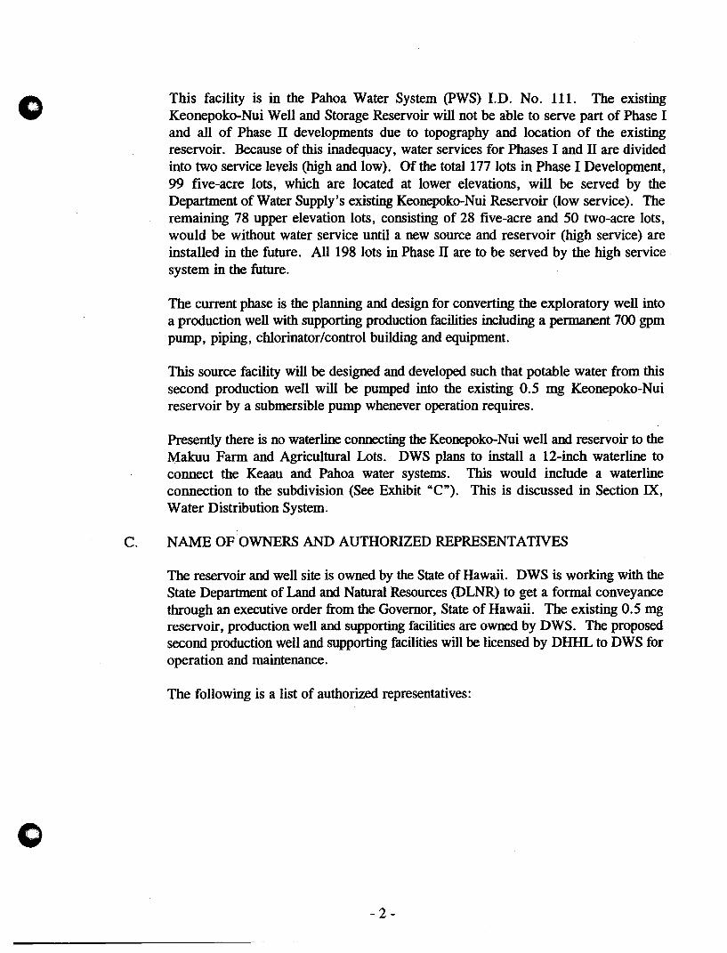
o This facility is in the Pahoa Water System (PWS) I.D. No. 111. The existing Keonepoko-Nui Well and Storage Reservoir will not be able to serve part of Phase I and all of Phase II developments due to topography and location of the existing reservoir. Because of this inadequacy, water services for Phases I and II are divided into two service levels (high and low). Of the total 177 lots in Phase I Development, 99 five-acre lots, which are located at lower elevations, will be served by the Department of Water Supply's existing Keonepoko-Nui Reservoir (low service). The remaining 78 upper elevation lots, consisting of 28 five-acre and 50 two-acre lots, would be without water service until a new source and reservoir (high service) are installed in the future. All 198 lots in Phase IT are to be served by the high service system in the future.
The current phase is the planning and design for converting the exploratory well into a production well with supporting production facilities including a permanent 700 gpm pump, piping, chlorinator/control building and equipment.
This source facility will be designed and developed such that potable water from this second production well will be pumped into the existing 0.5 mg Keonepoko-Nui reservoir by a submersible pump whenever operation requires.
Presently there is no waterline connecting the Keonepoko-Nui well and reservoir to the Makuu Farm and Agricultural Lots. DWS plans to install a 12-inch waterline to connect the Keaau and Pahoa water systems. This would include a waterline connection to the subdivision (See Exhibit "e"). This is discussed in Section IX, Water Distribution System.
C. NAME OF OWNERS AND AUTHORIZED REPRESENTATNES
The reservoir and well site is owned by the State of Hawaii. DWS is working with the State Department of Land and Natural Resources (DLNR) to get a formal conveyance through an executive order from the Governor, State of Hawaii. The existing 0.5 mg reservoir, production well and supporting facilities are owned by DWS. The proposed second production well and supporting facilities will be licensed by DHHL to DWS for operation and maintenance.
The following is a list of authorized representatives:
- 2-

...... '.':. ~.' .... ~. DETAILED LOCATIO~ MAP ./ .. /',", ,;'-..: ~.:. ~!;"
\
_ > '.' ">. . .' .,/ .. '._ OJ A".. -:., / ' .. _.' , • - /._ . ~ ... ~ • _,,-. v" / ... ...... •. / ." . . ". .~. ~~ )00 ~ ... ~ 4..... ~. +. ..; ,_ i-~'" / . /'
J ' • J N E iJ'l / . • •. • ~ ~ I ..... • • •• l· ~, :;..'\i.... . . :.' EXISTING W A TERL "'0./ .-. 0·· ..... · . .; 1 ... ,"+ • .(1.' .: ••••. -/>~ ... / o • '.';. ;". .~. ""\ . • ... ~ ".~~ ." I •. "i'. ." . • .~. ~"' .•• /_ 7 \-",' 1-t\.~.. .~. ,- ' •• /., .. .;',. - +., ............ .. ".. ; •• ",.. " •• -,m
• {<\~4W" •. ~"?,.~,>,, ..... ~ I .... '..... .• / <-.:- '_. .~) -,_.- '., _.. • ':~ , ~")t~. ~ ~ .~ '. "'!',o ' ...... ~.:. .. ..... ,",. ......, "-1 ~/ Ji V
0.' ,~.!.~ •• ~,,-~ • c...~:/'-: ..... / ... ~. "\... . .... ,( ~:" .. ~ ..;;".~r / Sy. ... ·' . J~ ••
" • .• '- ~ • • • ",-. Joo· ,.. • • / • \\;_ lIP, .. :.~ .~, , / ,""~.. • ~": ").- "~.. .~ .... '.. r.~. y'. ('
• ~~. c,-,..,.J '. • ~. /. . • . ... / . '-' c • ':>:~~. .:.~ '- ..... ..... '. ~J. .' ::. .;. • .. L..., .....' .• , ,.. ~ .. ·,v.. .. • ... ,...... . .. ' ... "'):"' \ ~. I ..{.' . / -:. .- . ..., ... . ". ../' . "
• ~' .... "'; ~+~ ~. . .... : ... ..c.: "",,- ,,/ ' . ..: ~ v • ...... "... +. ~ ',. '" : .... v .. -. -.. ~~.. _) I .'
~ / r;~ " ... '~ ~';,. ........ .,.. • \ .' -. '" I. .. . ". l· - '~ <." , / ~ .', +" .... ~ •• X "'''. '.".~':.,,,~ ............ /.::./ ,)
. .
':'::: 0" ' ~~~. +:' .. ~~f.l., ~. KE'A~'~-~~H~~ E'~;ENS'~'N' .
"X "X~, '.-.~~'. .. .... ~ .. ~.: PHASE- ,', : ~/!'\"
' ..
,. ./ /
... ...;;," ...... . '" ¥ .;~'?: . :''>\i\ >. (Sta. 60+00 t~ 'Sta .134+90)
,:t£,~ .. / ........ "", -..., , ~ .. . .-, _. ... 'r .~.:' -'-' ., ~ .... /. ........._ .... _
c,'". ..~ . .....' f :). ..... -...... - ~:~ '/ - .... J-' + .-." -. .. '~." ........ .4.1... ~ ~- .• '~- .... '.-.. -!
.... io +. ..~.. p .:,. ..", ... /- y/ ... "'\.... -". ~~_. /"" .. __ ..... .....-_., !t ... ,.. • • ", ~ ... ' I. ... 7,-__ ~,,,"..,,
'" "'~ £JJ ... ,\ ~.. .... / "? ,... .. ... l "I ...
..... . .;( ..... ~~ .. ~.~ ••• 7.\. ~~.:~/ ~ 0 • a \ ~. +." .... ..... • '£;)
v.. / •. ....... .. '-:::: .~. I, NOTE: " .. ; • . .... I ... ~ w"~'''''':II,(. -1.( 1. The Phase II & III Designations Coincide t""-
./~·.r.. .. 1 ~". 12 "~ ••. > .".'l"; ~th .'!he Dept ot Trans~':lation's ~oad . \..J
,. '... .... ~ "T. .. 7 ?._...... Improvement Projects. "
.... ;;( /. :; 2 This Project To Also Include Exploratory \-
• " .. ~.~~.dIO'- '~; Well Drilling At Sevation 600 Feet' \
_":!- :: .~~: • ." \-""~=-: C". . __ , _) /
J~.... .:: : '",:~t:~ T~ ~ ',_ ", .-~ + ~./. · .. . •.. '. y'/~"" t.. • • ". ; .. :; ...... •.•• •••• OJ ) ~ IF ',.('J'-. : i . " I ".-
1 •• ~ ... "- "., "".. • ~ ) ... ~; • ',I . . $£1 .. '.7..~ ..... /..,. .', ( ", "'. , .. / .
... I • • ..... ~ .. I ":.. ~;.. _/' .' \ ... , , " :
'4°·· .. ·• .';'.'/'" l' '., '-v--........ '-'O~ ." t" t ":;:.:-..1 ...... ,'. .. . J .. ';.' •• ~ ...... .,:.~ ./., ~\_ • ~ '.' '. :' /' .. ~ ~~ •. y. ... ~_ .. ! . . \. ;
.... • 1~ .: .. /. ~ .~ -'" S.J • ... .,,~;4 ...... -I ."~. , , • • .. . ~.... ....... r i" / • • .~ •• ?~ ~:. ft..!. / _~ I.'
."/3:\ ~'" .. ,~ .. :' .. ~':-.. '~"-'-- "-'1 / ".
~\' '\'\'" o"~.;:~~;.~.~ .. ~ ... ~~ . . ·~·~.:~~I !.' : (' KEAAU-PAHOA' EXTENSION ... \0 JI/:--... +,.~ '" /~~ ~~St 174+00) . '" '\ . \ ":-".~'?: ~ •• !f .. ~~~ .... ~ ... I'.. .a. -...........:.1 ~ .-/\..... . PH'ASE' III . r·.
t.. \ ..... At"" .... .... •• ,. . ...... ' .'. • .• • ~ I, L'-/ \... '. -. ~~.~. ~ .. ~ .... X. ": ... >~:."~,,~, "'0,\'" ". ':.~ "_'" (Sta.134+90 to Sta.174+00)
.. '~'IO~~ .~/ ........ wq.,.·. .. . I " ' ...... Ii ,_ •. "" ',' ~ ,l . ~t"'\' ;~ .. "'.... ... +,,' .~ ..... ··r./· ' . ". ,,- 52S~ :, . . \', . '\ .. ) rY
.. • .",~ .. ..... •• •• .. /' , • , • I...... , I \, I .'
:... \ '\ ••... \:\~ . ~ • ·TO"· BE DONE BY' :". ~l.._.' j:.. ~ / \".,., \ \ .\. \ DEPT. OF HAW' N HOMES LANDS \., '-" t). ::, ....... ", \~
.)\:~~:~~~~ft~? to.~ta._~;37+\O~: .. :" ~ ;-?,-.. ;~;z ~ ... '\ \. \ \ \ ~;~~ . (Sta.212+00)---~ '1 ... ~, L ~
) '. .~ t .... , , 0
:"~ •. \.'~ PUNA WATER DEVELOPMENT' ,._'\.. ... ' l., )'\.) l " ~ 1997-1998 CIP REQUEST ' J ~ ~ a" ';·-1"'--''-
KEAAU-PAHOA EXTENSION (12' TRUNK LINE) YC ~-s. ·/~=9~lttO .. PHASE" & PHASE III ._,-' / __ ._~ ~,.".<~~, c.;, o 0 EPARTMENT OF WATER S UPPL Y .,-1;' . ( .. \ : ,"1.--·1.'
'. " ,. " \
/
/ /
~
'.1
I..
/ · COUNTY OF HAWAII
EXHIBIT C
o
c
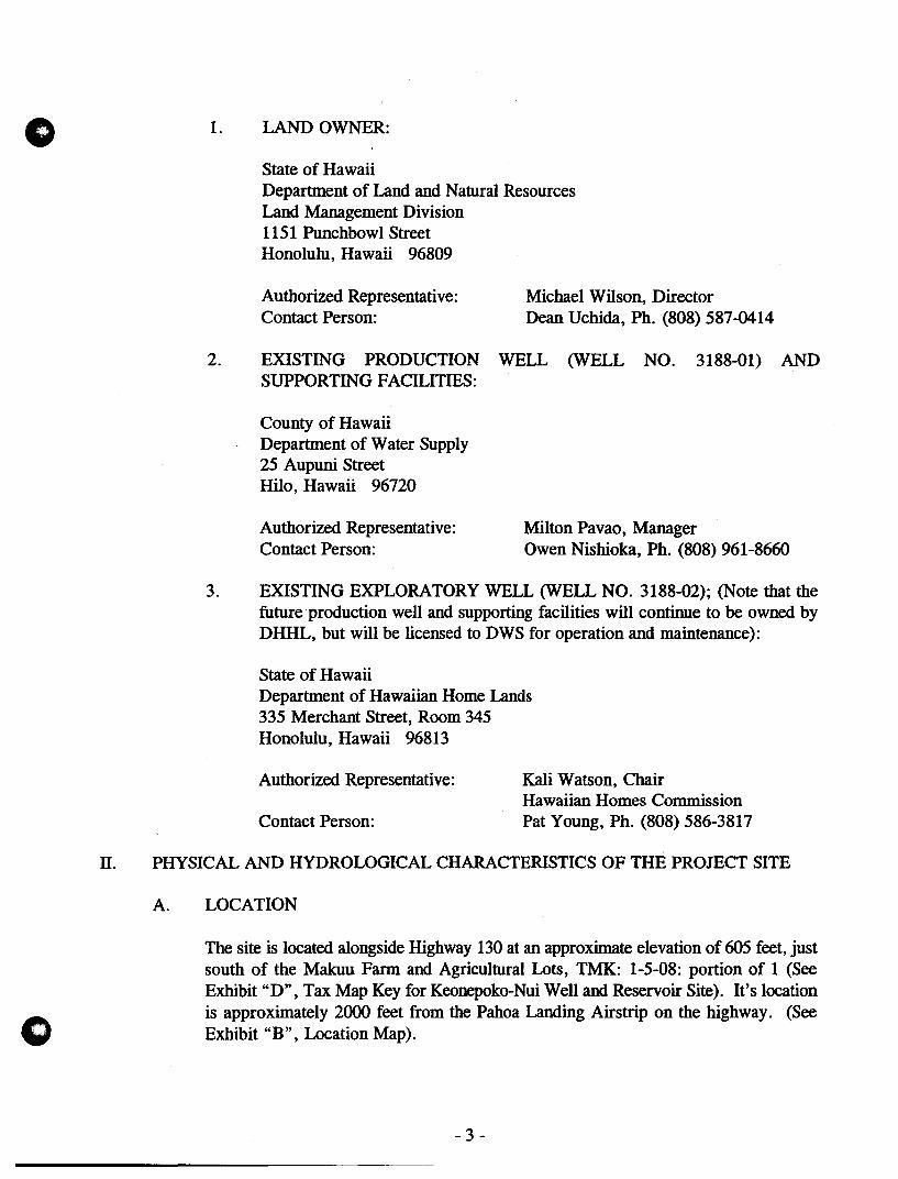
1. LANDOWNER:
State of Hawaii Department of Land and Natural Resources Land Management Division 1151 Punchbowl Street Honolulu, Hawaii 96809
Authorized Representative: Michael Wilson, Director Contact Person: Dean Uchida, Ph. (808) 587-0414
2. EXISTING PRODUCTION WELL (WELL NO. 3188-01) AND SUPPORTING FACILITIES:
County of Hawaii Department of Water Supply 25 Aupuni Street Hilo, Hawaii 96720
Authorized Representative: Contact Person:
Milton Pavao, Manager Owen Nishioka, Ph. (808) 961-8660
3. EXISTING EXPLORATORY WELL (WELL NO. 3188-02); (Note that the future· production well and supporting facilities will continue to be owned by DHHL, but will be licensed to DWS for operation and maintenance):
State of Hawaii Department of Hawaiian Home Lands 335 Merchant Street, Room 345 Honolulu, Hawaii 96813
Authorized Representative:
Contact Person:
Kali Watson, Chair Hawaiian Homes Commission Pat Young, Ph. (808) 586-3817
II. PHYSICAL AND HYDROLOGICAL CHARACTERISTICS OF THE PROJECT SITE
A. LOCATION
The site is located alongside Highway 130 at an approximate elevation of 605 feet, just south of the Makuu Farm and Agricultural Lots, TMK: 1-5-08: portion of 1 (See Exhibit "D", Tax Map Key for Keonepoko-Nui Well and Reservoir Site). It's location is approximately 2000 feet from the Pahoa Landing Airstrip on the highway. (See Exhibit "B" , Location Map).
- 3 -

·""~'
p
o
o -- --_ ..
", ::.:. ",
.. -.~-
o
'-,,' ~ ".
o
i II t-'). -I
~
\" ,
........ ..... ~. ", ~ '~' . o -/ " ' .0 / .... /
~. / ~. I
., I ,~ !
1;" V , "
PROJECT LO
/ /
/
EXISTING KEg·UION ,'U
WELL AND NEPOKO • /
..... JJ.~:::::. ___ S;;;.:I.:.:TE=--__ RESERVOIR .... » .,/. : ~/"
:::__ _" •• ~.4 ••
SA:::: -~~--..
--."eeL. t ..... ••••. ~. ... ....
wmce:o....... ::" .. _-=,--_ ....... .....: ...... '!; SI11.·,'1' .. l!
, .. ~.: I .. : ~.: /. ' . . • ; ... t,,;, .1."
----_ .. _ .. -
EXHIBIT D
o B.
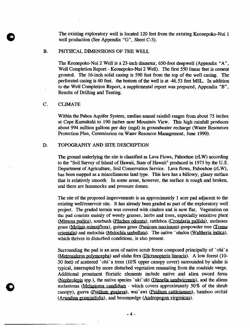
The existing exploratory well is located 120 feet from the existing Keonepoko-Nui 1 well production (See Appendix "Go., Sheet C-3).
PHYSICAL DIMENSIONS OF THE WELL
The Keonepoko-Nui 2 Well is a 23-inch diameter, 650-foot deepwell (Appendix" A", Well Completion Report - Keonepoko-Nui 2 Well). The ftrst 550 linear feet is cement grouted. The 16-inch solid casing is 590 feet from the top of the well casing. The perforated casing is 60 feet. the bottom of the well is at -46.53 feet MSL. In addition to the Well Completion Report, a supplemental report was prepared, Appendix "B", Results of Drilling and Testing.
C. CLIMATE
Within the Pahoa Aquifer System, median annual rainfall ranges from about 75 inches at Cape Kumukahi to 190 inches near Mountain View. This high rainfall produces about 994 million gallons per day (mgd) in groundwater recharge (Water Resources Protection Plan, Commission on Water Resource Management, June 1990).
D. TOPOGRAPHY AND SITE DESCRIPTION
The ground underlying the site is classifted as Lava Flows, Pahoehoe (rL W) according to the "Soil Survey of Island of Hawaii, State of Hawaii" produced in 1973 by the U.S. Department of Agriculture, Soil Conservation Service. Lava flows, Pahoehoe (rLW), has been mapped as a miscellaneous land type. This lava has a billowy, glassy surface that is relatively smooth. In some areas, however, the surface is rough and broken, and there are hummocks and pressure domes.
The site of the proposed improvements is an approximately 1 acre pad adjacent to the existing well/reservoir site. It has already been graded as part of the exploratory well project. The graded terrain was covered with cinders and is now flat. Vegetation on the pad consists mainly of weedy grasses, herbs and trees, especially sensitive plant (Mimosa pudica), sourbush (pluchea odorata), rattlebox (Crotalaria pallida), molasses grass (Melinis miuutiflora), guinea grass (Panicum maximum) gunpowder tree (Trema orientalis) and melochia (Melochia umbellata). The native 'uhaloa (Waltheria indica), which thrives in disturbed conditions, is also present.
Surrounding the pad is an area of native scrub forest composed principally of ' ohi' a (Metrosideros polymoq>ha.) and uluhe fern (j)icranopteris linearis). A low forest (10-30 feet) of scattered 'ohi' a trees (10% upper canopy cover) surrounded by uluhe is typical, interrupted by more disturbed vegetation emanating from the roadside verge. Additional prominent floristic elements include native and alien sword ferns (Nephrolepis spp.), the native species 'uki'uki (Dianella sandwicensis), and the aliens melastoma (Melastoma candidum - which covers approximately 50 % of the shrub canopy), guava (Psidium ~ajava), wai' awi (Psidium cattleianum), bamboo orchid (Arundina ~raminifolia), and broomsedge (AndrQpo~on yirginicus).
-4-
o
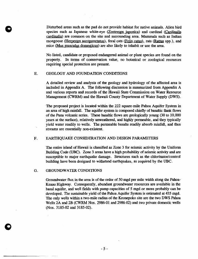
Disturbed areas such as the pad do not provide habitat for native animals. Alien bird species such as Japanese white-eye (Zostemps japonica) and cardinal (Cardinal is cardinalis) are common on the site and surrounding area. Mammals such as Indian mongoose (JIerpestes aUrQpunctatus), feral cats (Felis catus), rats (Rattus spp.), and mice (Mus musculus domesticus) are also likely to inhabit or use the area.
No listed, candidate or proposed endangered animal or plant species are found on the property. In terms of conservation value, no botanical or zoological resources requiring special protection are present.
E. GEOLOGY AND FOUNDATION CONDITIONS
A detailed review and analysis of the geology and hydrology of the affected area is included in Appendix A. The following discussion is summarized from Appendix A and various reports and records of the Hawaii State Commission on Water Resource Management (CWRM) and the Hawaii County Department of Water Supply (DWS).
The proposed project is located within the 222 square-mile Pahoa Aquifer System in an area of high rainfall. The aquifer system is composed chiefly of basaltic flank flows of the Puna volcanic series. These basaltic flows are geologically young (30 to 10,000 years at the surface), relatively unweathered, and highly permeable, and they typically yield water readily to wells. The permeable basalts readily absorb rainfall, and thus streams are essentially non-existent.
F. EARTHQUAKE CONSIDERATION AND DESIGN PARAMETERS
The entire island of Hawaii is classified as Zone 3 for seismic activity by the Uniform Building Code (UBC). Zone 3 areas have a high probability of seismic activity and are susceptible to major earthquake damage. Structures such as the chlorinator/control building have been designed to withstand earthquakes, as required by the UBC.
G. GROUNDWATER CONDITIONS
Groundwater flux in the area is of the order of 50 mgd per mile width along the PahoaKeaau Highway. Consequently, abundant groundwater resources are available in the basal aquifer, and well fields with pump capacities of 5 mgd or more probably can be developed. The sustainable yield of the Pahoa Aquifer System is estimated at 435 mgd. The only wells within a two-mile radius of the Keonepoko site are the two DWS Pahoa Wells 2A and 2B (CWRM Nos. 2986-01 and 2986-02) and two private domestic wells (Nos. 3185-02 and 3185-02).
- 5 -
o
o
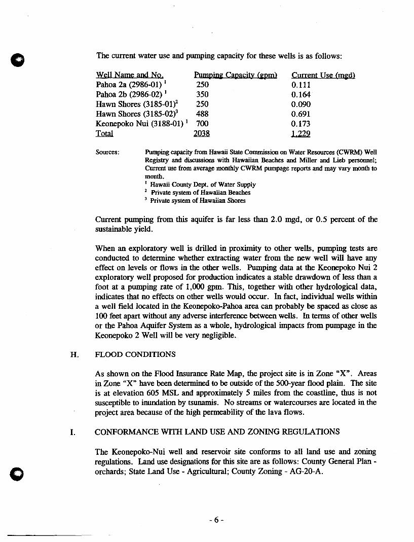
The current water use and pumping capacity for these wells is as follows:
Well Name and No. Pahoa 2a (2986-01) 1
Pahoa 2b (2986-02) 1
Hawn Shores (3185-Olf Hawn Shores (3185-02i Keonepoko Nui (3188-01) 1
Thtal
Pump~ Capacity (~ 250 350 250 488 700
2m8
Current Use (m~) 0.111 0.164 0.090 0.691 0.173 1.229
Sources: Pumping capacity from Hawaii State Commission on Water Resources (CWRM) Well Registry and discussions with Hawaiian Beaches and Miller and Lieb personnel; Current use from average monthly CWRM pumpage reports and may vary month to month. 1 Hawaii County Dept. of Water Supply 2 Private system of Hawaiian Beaches 3 Private system of Hawaiian Shores
Current pumping from this aquifer is far less than 2.0 mgd, or 0.5 percent of the sustainable yield.
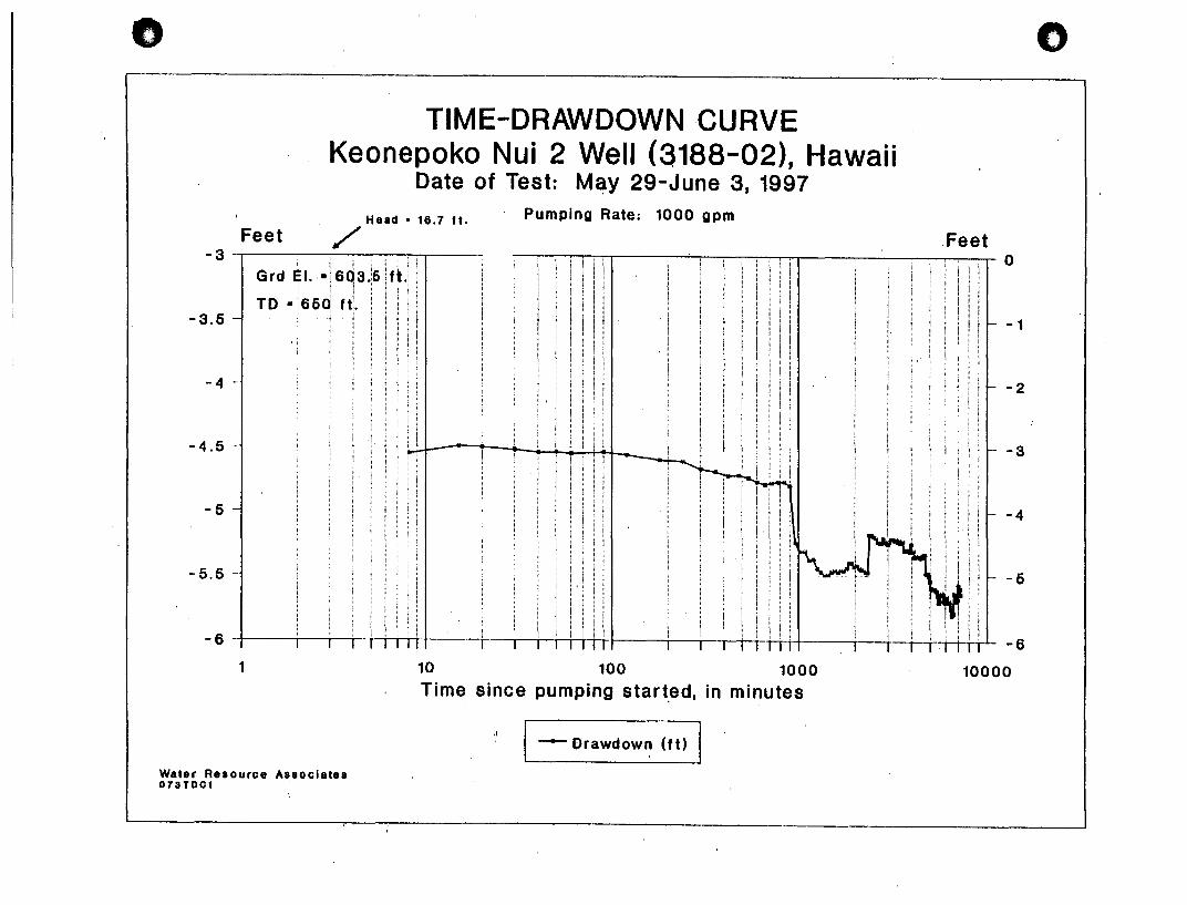
When an exploratory well is drilled in proximity to other wells, pumping tests are conducted to determine whether extracting water from the new well will have any effect on levels or flows in the other wells. Pumping data at the Keonepoko Nui 2 exploratory well proposed for production indicates a stable drawdown of less than a foot at a pumping rate of 1,000 gpm. This, together with other hydrological data, indicates that no effects on other wells would occur. In fact, individual wells within a well field located in the Keonepoko-Pahoa area can probably be spaced as close as 100 feet apart without any adverse interference between wells. In terms of other wells or the Pahoa Aquifer System as a whole, hydrological impacts from pumpage in the Keonepoko 2 Well will be very negligible.
H. FLOOD CONDITIONS
I.
As shown on the Flood Insurance Rate Map, the project site is in Zone "X". Areas in Zone "X" have been determined to be outside of the 500-year flood plain. The site is at elevation 605 MSL and approximately 5 miles from the coastline, thus is not susceptible to inundation by tsunamis. No streams or watercourses are located in the project area because of the high permeability of the lava flows.
CONFORMANCE WITH LAND USE AND ZONING REGULATIONS
The Keonepoko-Nui well and reservoir site conforms to all land use and zoning regulations. Land use designations for this site·are as follows: County General Planorchards; State Land Use - Agricultural; County Zoning - AG-20-A.
- 6 -
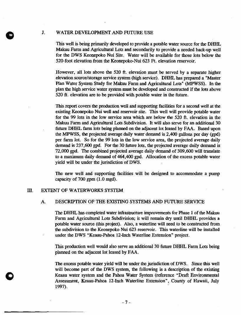
o J. WATER DEVELOPMENT AND FUTURE USE
This well is being primarily developed to provide a potable water source for the DHHL Makuu Farm and Agricultural Lots and secondarily to provide a needed back-up well for the DWS Keonepoko Nui Site. Water will be available for those lots below the 520-foot elevation ,from the Keonepoko-Nui 623 Ft. elevation reservoir.
However, all lots above the 520 ft. elevation must be served by a separate higher elevation source/storage service system (high service). DHHL has prepared a "Master Plan Water System Study for Makuu Farm and Agricultural Lots" (MPWSS). In the plan the high service water system must be developed and constructed if the lots above 520 ft. elevation are to be provided with potable water in the future.
This report covers the production well and supporting facilities for a second well at the existing Keonepoko Nui well and reservoir site. This well will provide potable water for the 99 lots in the low service area which are below the 520 ft. elevation in the Makuu Farm and Agricultural Lots Subdivision. It will also serve for an additional 30 future DHHL farm lots being planned on the adjacent lot leased by FAA. Based upon the MPWSS, the projected average daily water demand is 2,400 gallons per day (gpd) per farm lot. So for the 99 lots in the low service area, the projected average daily demand is 237,600 gpd. For the 30 future lots, the projected average daily demand is 72,000 gpd. The combined projected average daily demand of 309,600 will translate to a maximum daily demand of 464,400 gpd. Allocation of the excess potable water yield will be under the jurisdiction of DWS.
The new well and supporting facilities will be designed to accommodate a pump capacity of 700 gpm (1.0 mgd).
ill. EXTENT OF WATERWORKS SYSTEM
A. DESCRIPTION OF THE EXISTING SYSTEMS AND FUTURE SERVICE
The DHHL has completed water infrastructure improvements for Phase 1 of the MalalU Farm and Agricultural Lots Subdivision; it will remain dry until DHHL provides a potable water source (this project). Also, a waterline will need to be constructed from the subdivision to the Keonepoko Nui 623 reservoir. This waterline will be installed under the DWS "Keaau-Pahoa 12-Inch Waterline Extension" project.
This production well would also serve an additional 30 future DHHL Farm Lots being planned on the adjacent lot leased by FAA.
The excess potable water yield will be under the jurisdiction of DWS. Since this well will become part of the DWS system, the following is a description of the existing Keaau water system and the Pahoa Water System (reference "Draft Environmental Assessment, Keaau-Pahoa 12-Inch Waterline Extension", County of Hawaii, July 1997). .
-7-
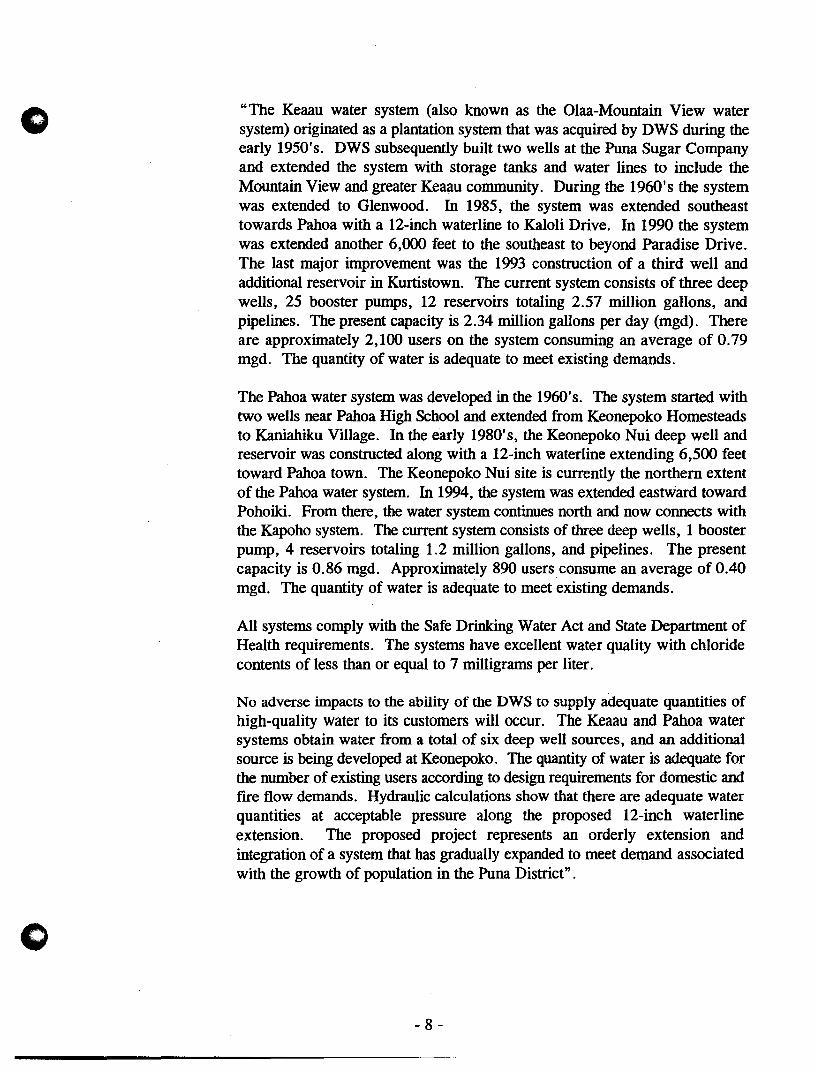
o "The Keaau water system (also known as the Olaa-Mountain View water system) originated as a plantation system that was acquired by DWS during the early 1950's. DWS subsequently built two wells at the Puna Sugar Company and extended the system with storage tanks and water lines to include the Mountain View and greater Keaau community. During the 1960's the system was extended to Glenwood. In 1985, the system was extended southeast towards Pahoa with a 12-inch waterline to Kaloli Drive. In 1990 the system was extended another 6,000 feet to the southeast to beyond Paradise Drive. The last major improvement was the 1993 construction of a third well and additional reservoir in Kurtistown. The current system consists of three deep wells, 25 booster pumps, 12 reservoirs totaling 2.57 million gallons, and pipelines. The present capacity is 2.34 million gallons per day (mgd). There are approximately 2,100 users on the system consuming an average of 0.79 mgd. The quantity of water is adequate to meet existing demands.
The Pahoa water system was developed in the 1960's. The system started with two wells near Pahoa High School and extended from Keonepoko Homesteads to Kaniahiku Village. In the early 1980's, the Keonepoko Nui deep well and reservoir was constructed along with a 12-inch waterline extending 6,500 feet toward Pahoa town. The Keonepoko Nui site is currently the northern extent of the Pahoa water system. In 1994, the system was extended eastward toward Pohoiki. From there, the water system continues north and now connects with the Kapoho system. The current system consists of three deep wells, 1 booster pump, 4 reservoirs totaling 1.2 million gallons, and pipelines. The present capacity is 0.86 mgd. Approximately 890 users consume an average of 0.40 mgd. The quantity of water is adequate to meet existing demands.
All systems comply with the Safe Drinking Water Act and State Department of Health requirements. The systems have excellent water quality with chloride contents of less than or equal to 7 milligrams per liter.
No adverse impacts to the ability of the DWS to supply adequate quantities of high-quality water to its customers will occur. The Keaau and Pahoa water systems obtain water from a total of six deep well sources, and an additional source is being developed at Keonepoko. The quantity of water is adequate for the number of existing users according to design requirements for domestic and fIre flow demands. Hydraulic calculations show that there are adequate water quantities at acceptable pressure along the proposed 12-inch waterline extension. The proposed project represents an orderly extension and integration of a system that has gradually expanded to meet demand associated with the growth of population in the Puna District".
- 8 -

o B.
o
DESCRIPTION OF SYSTEM POPULATION AND CONSUMPTION
This production well is being primarily developed to provide a potable water source for the DHHL Makuu Farm and Agricultural Lots. As described in an earlier section, the population being served by this well consists of 99 five-acre lots in the DHHL subdivision. The consumption criteria is from the MPWSS. It is summarized as follows:
The- following consumption criteria was used for this [MPWSS] study.
S/8" meter 1" meter
600 gpd 4200 gpd
Based on consumption data experienced by the Department of Hawaiian Home Lands on their agricultural subdivisions, it was learned that SO% of the lots will installS/8" meters and SO% will install 1 "meters. Therefore, an average daily demand of 2400 gpd (the average of the sum of S/8" meter and 1" meter consumption) is realistic and was used to arrive at the necessary improvements required for this water system. See Exhibit "E" for the Projected Water Demand.
Data from the 1990 Census of Population showed a total of approximately 16,000 persons living in Lower Puna outside of Keaau. Lower Puna has shown growth rates of over SO percent per decade in the last twenty years. By 1996, it is likely that the population of this section of Lower Puna will exceed 20,000.
Puna displays many of the characteristics of a disadvantaged region in its census statistics. The Pahoa-Kalapana Division (which includes most of the study area) in 1989 had a median household income of only $18,360, compared to $29,712 for the County as a whole. Thirty-two percent of individuals had income below the poverty level, a rate nearly SO percent larger than Hawaii County. More than 2S percent of those age 25 years or over have less than a high school education, and 16 percent have a work disability, compared to 22.3 percent and 9.6 percent, respectively, for the County as a whole:
Many of Puna's problems are related to the rudimentary infrastructure of the sprawling subdivisions which contain most of its population. These were well-suited for speCUlation but inadequate to serve the needs of the low and middle income families who have come to occupy the district. Needs often cited by Puna residents are additional paved roads, electricity, telecommunications facilities, water systems, schools, and recreation~l!acilities. Less than 2S percent of existing residences in the Lower Puna area are cT_entlY served by municipal domestic water systems.
- 9 -

In >C Z -• -... In
Exist. Keonepoko Reservoir. 623' (Low Service)
Phase I 5± Acres Lots
Total
Proposed Reservoir. 844' (High Service)
Phase I 5± Acres Lots 2± Acres Lots
Future Development 2± Acres Lots
Total
PROJECTED WATER DEMAND
No. of Units GPO/Unit
99 2400
28 2400 50 2400
198 2400
Average Annual' Day (GPD/GPM)
237.600/165.00
237.600/165.00
67.200/46.67 120.000/83.33
475.200/330.00
662,400/460.00
Max. Day Rate 1.5 x Average
(GPM)
247.50
247.50
70.00 125.00
495.00
690.00
o
Peak· Hour Rate 5.0 x Average
(GPM)
825.00
825.00
233.33 416.67
1650.00
2300.00

o
o
The areas most directly involved is the DHHL Makuu subdivision, which contains 177 lots, with a potential population of at least 530 (based on 3 residents per lot). A condition of connecting this development to the existing DWS system was the development of additional well capacity at Keonepoko Nui, which led to the proposed project. Other nearby areas directly affected include the highway frontage that is part of large parcels belonging to the State of Hawaii. The remaining area served by the additional well is essentially the entire Pahoa Water System.
Impacts
The continuing growth in population in this (and many other) areas of Puna brings with it a demand for upgraded water services. It is expensive and difficult for residents to maintain the quality and quantity of catchment water that is optimum for domestic use, especially consumptive use. Most residents, when given the option, will choose to connect to a public water system. The proposed project would allow DHHL beneficiaries to do so. In a larger context, the proposed project represents another step in the gradual upgrading of infrastructure in the Puna District. There will be no other impacts, beneficial or adverse, upon other small or large landowners in the immediate or extended area, apart from those benefits accruing to all system users as a result of increased system reliability and capacity. Water projects may involve the potential for substantial secondary impacts associated with induced population growth. Currently, water service is available only to those lots with highway frontage. However, the growth pattern in the Puna subdivisions that have some highway frontage - fairly evenly spread throughout - suggests that water is not an overwhelming factor in the decision of the potential home builder about where to build. Lower lot prices, seclusion, preferred vegetation, and proximity to the ocean also appear to play large roles. Many lots with highway frontage and/or access to water remain undeveloped. The project will ensure that as orderly growth of the water main infrastructure (which, rather than capacity - is the restricting factor in the water service area) eventually and gradually supplies water to the subdivisions, capacity will not be a problem. The scale of the project set in the context of the existing rate of growth indicates that secondary impacts would be unlikely or negligible.
C. APPRAISAL OF FUTURE REQUIREMENTS OF SYSTEM
The proposed installation of a permanent 700 gpm pump translates into a well capacity of 1.0 mgd. This is more than adequate to satisfy the present projected average daily demand of 0.24 mgd for the existing 99 lots in the subdivision's low service area. It is also adequate to supply the projected 0.07 mgd for the 30 future lots in the low service area.
The remaining 78 in phase I and the future 198 lots in Phase IT will be without water service until a new source and reservoir (high service) are installed in the future. The projected future average daily demand is 0.66 mgd.
- 10-
o
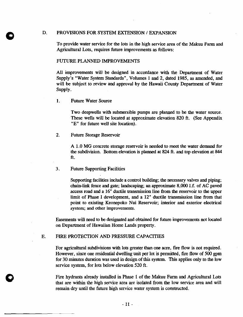
D. PROVISIONS FOR SYSTEM EXTENSION I EXPANSION
To provide water service for the lots in the high service area of the Makuu Fann and Agricultural Lots, requires future improvements as follows:
FUTURE PLANNED IMPROVEMENTS
All improvements will be designed in accordance with the Department of Water Supply's "Water System Standards", Volumes 1 and 2, dated 1985, as amended, and will be subject to review and approval by the Hawaii County Department of Water Supply.
1. Future Water Source
Two deepwells with submersible pumps are planned to be the water source. These wells will be located at approximate elevation 820 ft. (See Appendix "E" for future well site location).
2. Future Storage Reservoir
A 1.0 MG concrete storage reservoir is needed to meet the water demand for the subdivision. Bottom elevation is planned at 824 ft. and top elevation at 844 ft.
3. Future Supporting Facilities
Supporting facilities include a control building; the necessary valves and piping; chain-link fence and gate; landscaping; an approximate 8,000 I.f. of AC paved access road and a 16" ductile transmission line from the reservoir to the upper limit of Phase I development, and a 12" ductile transmission line from that point to existing Keonepoko Nui Reservoir; interior and exterior electrical system; and other improvements.
Easements will need to be designated and obtained for future improvements not located on Department of Hawaiian Home Lands property.
E. FIRE PROTECTION AND PRESSURE CAPACITIES
For agricultural subdivisions with lots greater than one acre, fIre flow is not required. However, since one residential dwelling unit per lot is permitted, fire flow of 500 gpm for 30 minutes duration was used in design of this system. This applies only to the low service system, for lots below elevation 520 ft.
Fire hydrants already installed in Phase 1 of the Makuu Farm and Agricultural Lots that are within the high service area are isolated from the low service area and will remain dry until the future high service water system is constructed.
- 11 -
o
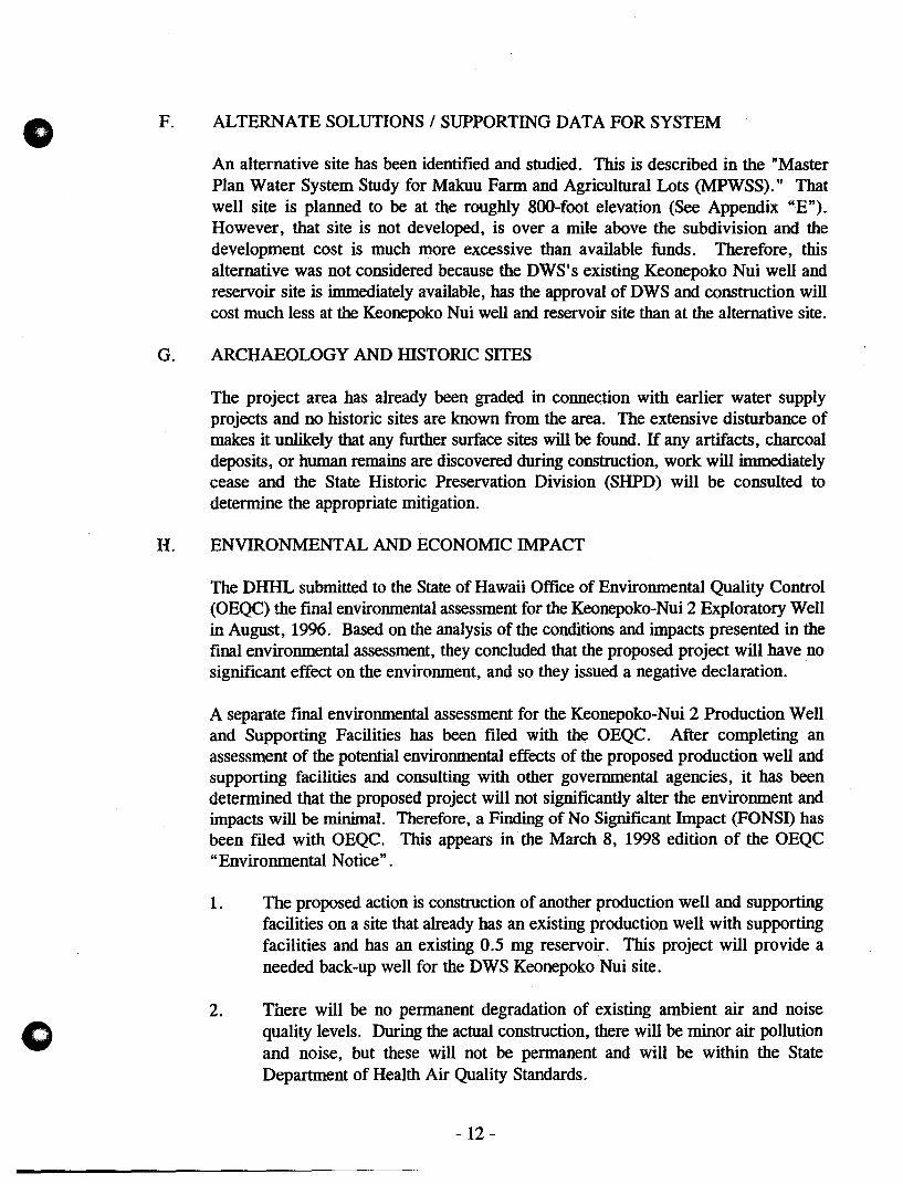
F. ALTERNATE SOLUTIONS / SUPPORTING DATA FOR SYSTEM
An alternative site has been identified and studied. This is described in the "Master Plan Water System Study for Makuu Farm and Agricultural Lots (MPWSS)." That well site is planned to be at the roughly 8oo-foot elevation (See Appendix "'E"). However, that site is not developed, is over a mile above the subdivision and the development cost is much more excessive than available funds. Therefore, this alternative was not considered because the DWS's existing Keonepoko Nui well and reservoir site is immediately available, has the approval of DWS and construction will cost much less at the Keonepoko Nui well and reservoir site than at the alternative site.
G. ARCHAEOLOGY AND mSTORIC SITES
The project area has already been graded in connection with earlier water supply projects and no historic sites are known from the area. The extensive disturbance of makes it unlikely that any further surface sites will be found. If any artifacts, charcoal deposits, or human remains are discovered during construction, work will immediately cease and the State Historic Preservation Division (SHPD) will be consulted to determine the appropriate mitigation.
H. ENVIRONMENTAL AND ECONOMIC IMPACT
The DHHL submitted to the State of Hawaii Office of Environmental Quality Control (OEQC) the fmal environmental assessment for the Keonepoko-Nui 2 Exploratory Well in August, 1996. Based on the analysis of the conditions and impacts presented in the final environmental assessment, they concluded that the proposed project will have no significant effect on the environment, and so they issued a negative declaration.
A separate final environmental assessment for the Keonepoko-Nui 2 Production Well and Supporting Facilities has been filed with the OEQC. After completing an assessment of the potential enviromnental effects of the proposed production well and supporting facilities and consulting with other governmental agencies, it has been determined that the proposed project will not significantly alter the environment and impacts will be minimal. Therefore, a Finding of No Significant Impact (FONSn has been filed with OEQC. This appears in the March 8, 1998 edition of the OEQC "Environmental Notice".
1. The proposed action is construction of another production well and supporting facilities on a site that already has an existing production well with supporting facilities and has an existing 0.5 mg reservoir. This project will provide a needed back-up well for the DWS Keonepoko Nui site.
2. There will be no permanent degradation of existing ambient air and noise quality levels. During the actual construction, there will be minor air pollution and noise, but these will not be permanent and will be within the State Department of Health Air Quality Standards.
- 12-

o
(.)
3. There are no known endangered species of animal or plants within the project site.
4. There are no natural, historic, or archaeological sites within the project site.
5. The project is consistent with DWS plans for water source development. Potable water well development by the Department is a permitted use by the State and County zoning designations.
6. This project will provide potable water for the low service system of DHHL's Makuu Farm and Agricultural Lots Subdivision. Phase I has just been completed and has been turned over to Hawaii County for infrastructure maintenance. Any adverse impacts of the proposed project have been determined to be insignificant. The applicant will comply with applicable statutes, ordinances, and rules of the Federal, State, and County governments during the implementation of this project.
N. POTENTIAL SOURCES OF CONTAMINATION
A. DESCRIPTION OF WELL SITE
B.
Keonepoko-Nui 2 Well, State Well No. 3188-02, is located on the existing KeonepokoNui Well and reservoir site, latitude 19-30'-53" and longitude 154-57'-53". The latitude and longitude are based on NAD 83 Geographic Coordinates and map provided by DWS.
The top of the casing of the well is elevation 605.55 feet MSL and the bottom of the well is at -46.53 feet MSL. The topography of the surrounding area is relatively flat, vegetated mostly with bushes and grass. Other vegetation include ohia and guava trees. The ground underlying the site is classified as Lava Flows, Pahoehoe (rLW). The static water level is at elevation 586.7 feet below ground, which is 16.8 MSL (See Appendix "A", Well Completion Report).
ORIENTATION MAPS
Exhibit F contains maps of existing drywells and individual wastewater systems in relation to water wells. There are no streams or known wetlands within many miles of the project area, and there will be no effect on such. The area surrounding the well is mostly undeveloped land belonging to the State of Hawaii. No formal wellhead protection area is required or in place for the well, but in any case there are no drywells or landftlls, hazardous waste sites, or injection wells within the 1,320-foot radius regulated by the Hawaii State Department of Health's (DOH) Safe Drinking Water Branch. Two individual wastewater systems pre-dating the Keonepoko Nui wells are present approximately 800 feet from the well; under DOH rules, new individual wastewater systems would be prohibited or severely restricted within a 1,000 foot radius of the well.
- 13 -

o
~
c
.,.t6
"!'
39
~Gl"" ~~. '%~?t. • ~ GI.~
q.. o~1(,/fI =- .. ',~~ ..
'i3~~ .." '!;,~. .... ~" ...
.."
25 I 26 I 27 I 26 II'J' I 30 • •
'8 I 17 I 16 I 15 14 I IJ I 12
INDMDU4L WASTEWATER SYSTEM (PRNAT£)
.".- .... ----- ....... £X1ST/NG 0')' ~ M.G. RESERVOIR ,
To Future High Water Service Source
EXISTING , EXPLORATORY wru
\ \ \
PLAN SHOWING EXISTING DRWIfl' S AND INDMOlW- WASTEWATER stSJEMS IN REI ADON TO WATER WfI' S
SCAlE: 1-_600' EXHIBIT E
o
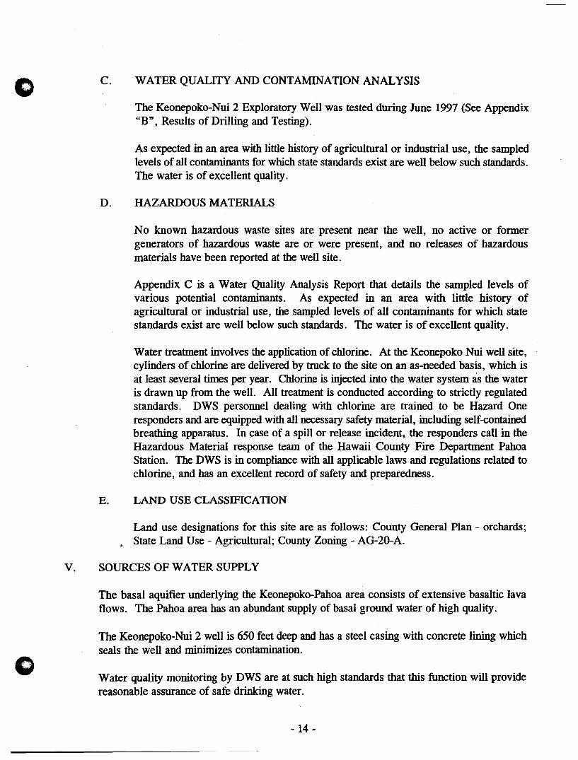
C. WATER QUALITY AND CONTAMINATION ANALYSIS
The Keonepoko-Nui 2 Exploratory Well was tested during June 1997 (See Appendix "B", Results of Drilling and Testing).
As expected in an area with little history of agricultural or industrial use, the sampled levels of all contaminants for which state standards exist are well below such standards. The water is of excellent quality.
D. HAZARDOUS MATERIALS
No known hazardous waste sites are present near the well, no active or former generators of hazardous waste are or were present, and no releases of hazardous materials have been reported at the well site.
Appendix C is a Water Quality Analysis Report that details the sampled levels of various potential contaminants. As expected in an area with little history of agricultural or industrial use, the sampled levels of all contaminants for which state standards exist are well below such standards. The water is of excellent qUality.
Water treatment involves the application of chlorine. At the Keonepoko Nui well site, cylinders of chlorine are delivered by truck to the site on an as-needed basis, which is at least several times per year. Chlorine is injected into the water system as the water is drawn up from the well. All treatment is conducted according to strictly regulated standards. DWS personnel dealing with chlorine are trained to be Hazard One responders and are equipped with all necessary safety material, including self-contained breathing apparatus. In case of a spill or release incident, the responders call in the Hazardous Material response team of the Hawaii County Fire Department Pahoa Station. The DWS is in compliance with all applicable laws and regulations related to chlorine, and has an excellent record of safety and preparedness.
E. LAND USE CLASSIFICATION
Land use designations for this site are as follows: County General Plan - orchards; • State Land Use - Agricultural; County Zoning - AG-20-A.
v. SOURCES OF WATER SUPPLY
The basal aquifier underlying the Keonepoko-Pahoa area consists of extensive basaltic lava flows. The Pahoa area has an abundant supply of basal ground water of high quality.
The Keonepoko-Nui 2 well is 650 feet deep and has a steel casing with concrete lining which seals the well and minimizes contamination.
Water quality monitoring by DWS are at such high standards that this function will provide reasonable assurance of safe drinking water.
- 14-

o
o
VI. PROPOSED TREATMENT WORKS
The existing Keonepoko-Nui 1 well has a gas chlorinator that provides disinfection treatment and its connected to a 0.5 mg reservoir that provides the necessary contact time to inactivate pathogens.
The proposed second production well will likewise have a separate gas chlorination system in a separate control building.
The operation of the existing production well and disinfection system are automatic. The second production well and disinfection system will also be automatic. The disinfection residual will be checked by DWS per their operational monitoring standards.
VII. PUMPING FACILITIES
The existing Keonepoko-Nui 1 Well (Well No. 3188-01) has an installed pump capacity of 700 gpm.
The proposed second production well will also have an installed pump capacity of 700 gpm. The well pumping unit specifications are in Appendix "D" and subject to actual installation approved by DWS.
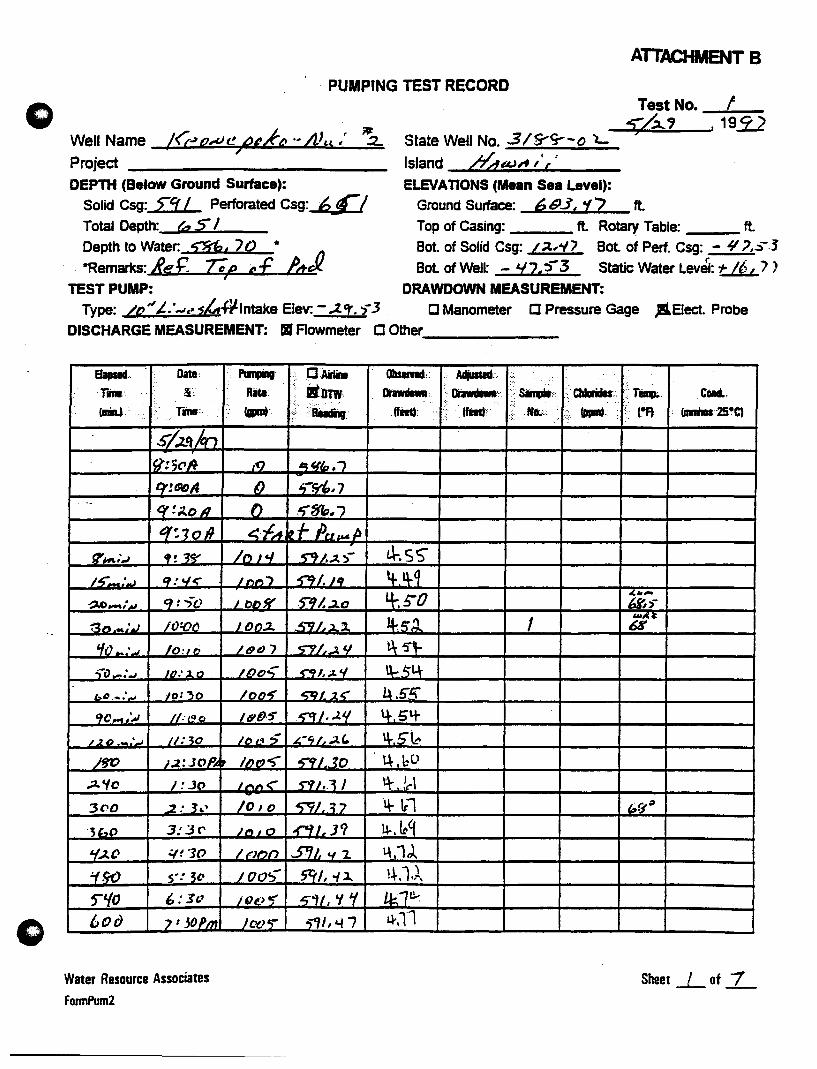
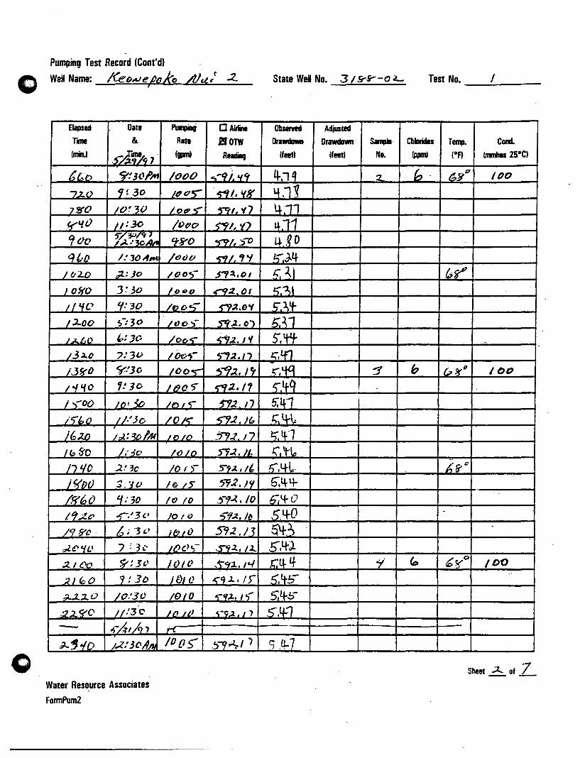
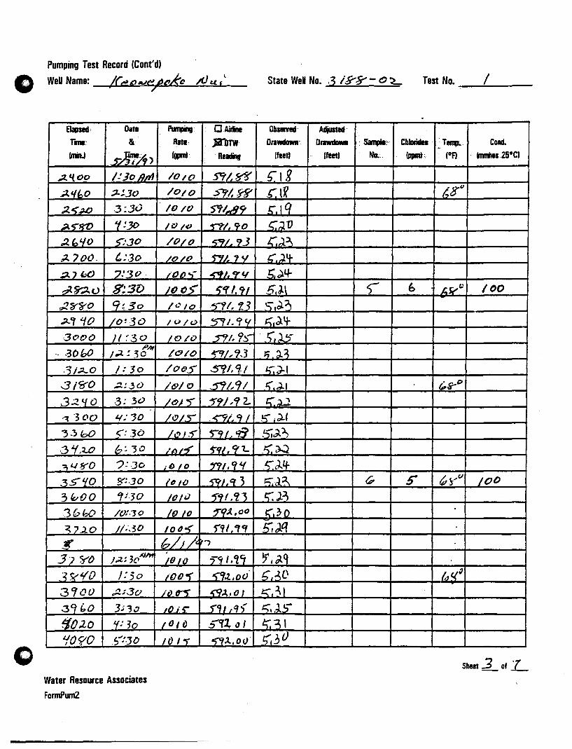
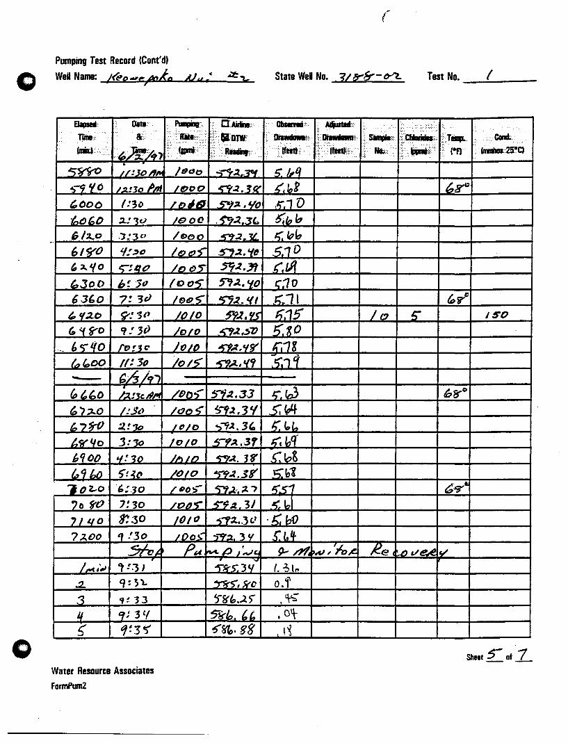
The pumping test records are in Appendix "B", Results of Drilling and Testing.
The piping layout is in Appendix "F".
VIII. FINISHED WATER STORAGE
IX.
There is an existing DWS 0.5 mg concrete reservoir on this site which the new well will discharge into.
WATER DISTRIBUTION SYSTEM
This second production well is being developed specifically to provide a potable water source for the DHHL Makuu Farm and Agricultural Lots Subdivision. Presently there is no waterline connecting the Keonepoko-Nui Well and reservoir to the subdivision. DWS plans to install a 12-inch waterline to connect the Keaau and Pahoa water systems. This would include a waterline connection to the subdivision. The DWS project is called "Keaau-Pahoa 12-Inch Waterline Extension". The new waterline will extend 17,750 feet between Paradise Drive in Hawaiian Paradise Park (Station 60+00) to the Keonepoko-Nui well and reservoir (Station 237 + 50). This is shown on Exhibit "C". DHHL has built a portion of this waterline as part of their Makuu Farm and Agricultural Lots Subdivision. This part of the waterline is from Station 174+00 to Station 212+00. The new waterline from Station 212+00 to Station 237 +00 (2500 linear feet) will connect the Keonepoko-Nui well and reservoir to the Makuu Farm and Agricultural Lots.
- 15 -
o
o
x.
DWS plans to install this waterline at the same time the Hawaii State Department of Transportation's (HDOT) Keaau-Pahoa Highway Improvement Project (FAP No. &5-0130 [24]) is constructed. Construction for both the highway and waterline projects is scheduled to begin in 1998 and both will be fInished within approximately 18 months.
FINANCING
The cost for drilling, casing and testing of the exploratory well is $ 0.6 million. This is being paid by the State of Hawaii, DHHL.
The estimated cost of the production well and supporting facilities is estimated to be $1 million. This will also be paid by the State of Hawaii, DHHL.
XI. PROFESSIONAL ENGINEER CERTIFICATION
The undersigned, being a registered professional engineer, certifIes that:
He has prepared this report and the information contained therein is true to the best of his information and belief; and
The water produced by Keonepoko-Nui 2 Well, State No. 3188-02, the Pahoa Water System, LD. 111, will comply with the State primary potable water regulations contained in Hawaii Administrative Rules, Title 11, Chapter 20, Rules Relating to Potable Water Systems, and will comply with the Rules and Regulations of the Department of Water Supply, County of Hawaii, since this source and system will be operated and maintained by the Department of Water Supply, County of Hawaii.
This report was prepared by me or under my supervision.
Eric N.S. Hee, P.E. Engineers Surveyors Hawaii, Inc.
- 16-
o
DEPARTMENT OF WATER SUPPLY • COUNTY OF HAWAII 25 AUPUNI STREET • HILO. HAWAII 96720
TELEPHONE (808) 961-8660 • FAX (808) 961-8657
November 7, 1997
Mr. Eric Hee, P.E. Engineers Surveyors Hawaii, Inc. 1020 Auahi Street Suite No.1, Building NO.6 Honolulu. HI 96814
KEONEPOKO-NUI 2 PRODUCTION WELL AND SUPPORTING FACILITIES (MAKUU OFFSITE WATER - PHASE 2)
[ffi EGa HI IE lD) NOV 10 1997
ENGINEERS SURVEYORS HAWAII, INC.
We reviewed the engineering report for the subject project and have no comments to off
ON:gms
copy - DWS Engineering Division - Microlab
. .. Wale,. t"ing~ progre~~ ...
o
o
xm. REFERENCES
County of Hawaii, "Draft Environmental Assessment, Keaau-Pahoa 12-Inch Waterline Extension", July 1997.
Commission of Water Resource Management, "Water Resources Protection Plan", June 1990.
Hawaii County Department of Water Supply, "Hawaii County Water Use and Development Plan", 1992.
Hawaii Department of Health, Rules Relating to Potable Water Systems, Title 11, Chapter 20, Hawaii Administrative Rules, November 1994.
Hawaii Department of Health, Underground Injection Control, Title 11, Chapter 23, Hawaii Administrative Rules, September 1992.
State of Hawaii, Department of Hawaiian Home Lands, "Final Environmental Assessment and Negative Declaration, Keonepoko-Nui 2 Exploratory Well", August 1996.
State of Hawaii, Department of Hawaiian Home Lands, "Final Environmental Assessment, Keonepoko-Nui 2 Production Well and Supporting Facilities", February 1998.
State of Hawaii, Department of Hawaiian Home Lands, "Master Plan Water System Study for Makuu Farm and Agricultural Lots", July 1994.
U.S.D.A., Soil Conservation Service, "Soil Survey of Island of Hawaii, State of Hawaii", 1973.
Water Resource Associates, "Hydrologic Feasibility of Additional Well Source at Keonepoko Reservoir Site (DWS), HHL Makuu Farm Lots, Pahoa, Puna, Hawaii", 1996.
- 17 -
o
APPENDIX A
WELL COMPLETION REPORT
KEONEPOKO NUl 2 WELL (3188-02)
G WATER RESOURCE ASSOCIATES
o
Hydrology • Geology • Engineering
Ms. Rae Loui Deputy Director Commission on Water Resource Management Department of Land & Natural Resources P.O. Box 621 Honolulu, Hawaii 96809
Dear Ms. Loui:,
July 29, 1997
[ffi ~ @ ~ ~ ;H !OJ JUl 3 1 ,'117,
:NGINEEffS SURVEYORS HAWAII. iNC.
Well Completion Report Keonepoko Nui 2 Well (3188-02), Hawaii
Enclosed is the Well Completion Repon for Keonep~ko Nui 2 Well.
We have satisfied all conditions of the Pennit and we request, on behalf of the applicant, your approval of a permit to install a permanent pump with a capacity of 700 gpm.
Enc. c:
Please call me if there are any questions.
Mr. Eric Hee, ESH / Mr: Kali Watson, DHHL
1708
Sincerely,
DANLUM
1188 Bishop Street. Suite 6G+. Honolulu. Hawaii 96813-3302 • (808) 528-0074 • Fax 528-0808
State of Hawaii COMMISSION ON WATER RESOURCE MANAGEMENT Department of Land and Natural Resources
WELL COMPLETION REPORT 3I2OJ96 WCR Form
(Check Appropriate Box) DWell Construction o (Permanent) Pump InstaUation
Instructions: Please print or type and submit completed report wiIhin 30 days after wei completion to the Commiuion on Water Resource Management. P.O. Box 621, Honolulu, .Hawlli 96809. An as-buil drawing of the wei and chemical analysis should also be submilled. For assistance call the Commission Regulation Branch at 587-0225, or 1-«1O-46a-.644 Extension 70225.
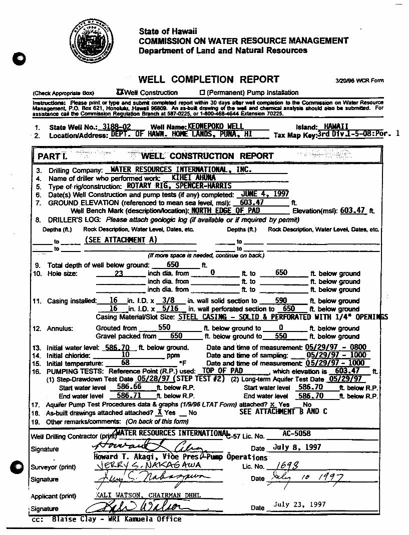
1. State Well No.: 311-f Well Name: KEONEPOKO WELL ·2. Location/Address: P. OF HAWN. HOME LANDS, pUNA, HI
Island: HAWAI I Tax Map Key:3rd biyJ-5::oa:Por. 1
···':'·;:;-:·::·WELt::· CONSTRUCTION REPORT ....... : .. :::: .. : ......... .
3. Drilling Company: WATER RESOURCES INTERNATIONAl.., INC. 4. Name of driller who performed work: KIHEI AHUIIA 5. Type of- rig/construction: ROTARY RI·~G"'::, ~S::PE=N:n;C=ER;:.;:-~HA:::::RR=I=S -----6. Date(s) Well Construction and pump tests (if any) completed: JUNE 4, 1997 7. GROUND ELEVATION (referenced to mean sea level, msl): 603.47 fl
Wei Bench Mark (descriptionllocation): NORTH EDGE OF PAD Elevation(msl): 603.47 fl 8. DRILLER'S LOG: Please attach geologic log (if available or if required by pennit)
Depths (fl) Rock Desaiption, Water Level. Dates, etc. Depths (ft.) Rock Desaiption, Water Level, Dates. etc.
__ to __ (SEE ATTACiltENT A) __ to ____________ _ __ to_-_ _to _____________ 1
(If mote space is needed, continue on back.)
9. Total depth of well below ground: 650 fl 10. Hole size: 23 inch dia. from 0 fl to 650 fl below ground
_____ inch dia. from fl to fl below ground _-.-___ inch dia. from fl to fl below ground
11. Casing installed: 16 in. 1.0. x 3/8 in. wall solid section to 590 fl below ground 16 in. 1.0. x 5/16 in. wall perforated section to 650 fl below ground
Casing MateriaUSIot Size: STEEL CASING - SOLID & PERFORATED WITH 1/4- OPENI 12. Annulus: Grouted from 550 fl below ground to 0 fl below ground
Gravel packed from 650 fl below ground to 550 fl below ground
1"3. Initial water level: 586,70 fl below ground. Date and 'time of measurement 05/29/97 - 0800 14. Initial chloride: 10 ppm Date and time of sampling: _ 95/29/97 - 1000 15. Initial temperature: 68 OF Date and time of measurement 95/29/97 - 1000 16. PUMPING TESTS: Reference Point (RP.) used: TOP OF PAD , which elevation is 603.47 fl
(1) SteJH)rawdown Test Date 05/28/97 (STEP TEST 12) (2) Long-term Aquifer Test Date 05/29/97 Start water levet 586.66 fl below R.P. Start water levet 586.70 ft. below RP. End water levet 586.71 fl below R.P. End water levet 586 • .70 fl below RP.
17. Aquifer Pump Test Procedures data & graphs (119196 LTAT Fonn) attached? 1L Yes _ No 18. As-built drawings attached attached? ~ Yes _ No SEE ATTACIlENT BAND C 19. Other remarks/comments: (On baclc of this (onn)
Well Drilling Contractor (p. t TER RESOURCES INTERNATIO~_57 Uc. No. AC-5058 ---------------------Signature
e> Surveyor (print)
Signature
Applicant (print)
Date July 8, 1997 oward T. Akagi, Vi Pres PUIIIP Operations
rt:~ ~No. ,f619. -"'7 ~~ Date /~ I~ 1197 : :; 7 7
Date July 23, 1997

3I20I9l WCR F_
PART II. (PERMAt4ENT),.PUMP INSTALLA flON REPORT·,· •• ·•·
C1 ..
20. Pump Installation Company: 21. Name of person performing work: 22. Date Pump Installation Completed: 23. PUMP INSTALLATION:
Pump-Type, Make, Serial No.: Capacity: gpm Motor type, H.P., Voltage, rpm: Depth of Pump Intake Setting fl below • which elevation is ft Depth to bottom of airline ft.below , which elevation is ft
' .. Pumping Head is ft. Type of flow meter: which measans in 24. As-built drawingS attached attached? _ Ves _ No 25. Other remarks/comments: (See below)
Pump Installation Contractor (print) C-57 Uc. No.
Signature Date
Applicant (print)
Signature Date
8. (cont'd) DRILLER'S LOG (confd): Water level Depth (ft.) Rock Description; Remarks, Water level - Depth (ft.) Rock Desaiption, Remarks,
Dates (ft.) Dates (ft.)
----~--------------------------- -~--- -------------____ to ______ ~ __________________ _
---~---------------------------~---------------------------
_to _________________ _
----~---------------------------_ 10 __________ ------
----~------------------------~- ----~-------------------------~--------------------------- ----~---------------------____ to _____________________ _ ___ 10 _________________________ _
----~----------------------- ----~----------------------
. . 19.& 25. Remarks: _P_UMP_I_rf_G __ T_ES_T_DA_T_A_A_TT_A_CH_E_D_.-_-_S=E=E;....;A..;.;TT~A;..;.;C=fItE=NT.:...:.-;:B=-A:;.,;:N=D:-,C=---_____ _
o
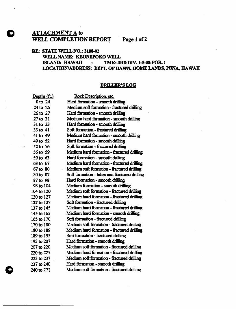
ATIACHMENT A to WELL COMPLETION REPORT Page 1 of2
RE: STATE WELL NO.: 3188-02 WELL.NAME: KEONEPOKO WELL ISLAND: HAW An TMK: 3RD DIV. l-S-08:POR. 1 LOCATION/ADDRESS: DEPT. OF HAWN. HOME LANDS, PUNA, HAW An
PeRths eft.> Oto 24
24to 26 26to 27 27to·31 31 to 33 33 to 41 -41 to 49 49to 52 52 to 56 56to 59 59to 63 63 to 67 67to 80 80to 87 87to 98 98 to 104
104 to 120 120 to 127 127 to 137 137 to 145 145 to 165 165 to 170 170 to 180 180 to 189 189 to 195 195 to 207 207 to 220 220 to 225 225 to 237 237 to 240 240 to 271
DRILLER'S LOG
Rock DesaiptioD. etc. Hard formation - smooth drilling Medium soft formation - fractmed drilling Hard formation - smooth drilling Medium hard formation - smooth drilling Hard formation - smooth drilling Soft formation - fractmed drilling Medium hard formation - smooth drilling ~ formation - smooth drilling Soft fonnation - fractmed drilling Medium hard formation - fractured drilling Hard formation - smooth drilling Medium hard formation - fractured drilling Medium soft formation - fractured drilling Soft formation - tubes and fractured drilling Hard formation - smooth drilling Medium formation - smooth drilling Medium soft formation - fractmed drilling Medium hard formation - fractmed drilling Soft fonnation - fractured drilling Medium hard formation - fractured drilling Medium hard formation - smooth drilling Soft formation - fractmed drilling Medium soft formation - fractured drilling Medium hard formation - fractured drilling Soft formation - fractured drilling Hard formation - smooth drilling Medium soft formation - fractmed drilling Medium hard formation - fractured drilling Medium soft formation - fractured drilling Hard formation - smooth drilling Medium soft formation - fractmed drilling
o
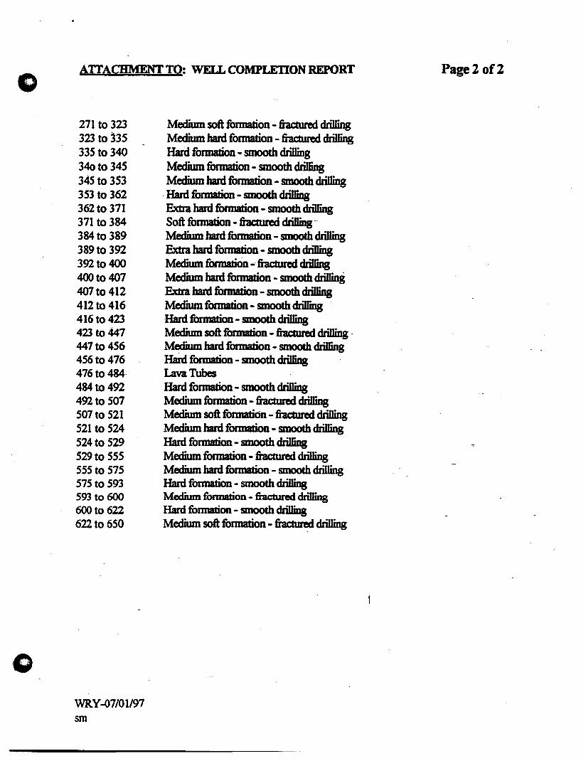
AITACHMENT TO: WELL COMPLETION REPORT
271 to 323 323 to 335 335 to 340 340 to 345 345 to 353 353 to 362 362 to 371 371 to 384 384 to 389 389 to 392 392 to 400 400 to 407 407 to 412 412 to 416 416 to 423 423 to 447 447 to 456 456 to 476 476 to 484-484 to 492 492 to 507 507 to 521 521 to 524 524 to 529 529 to 555 555 to 575 575 to 593 593 to 600 600 to 622 622 to 650
WRY -fJ7/01l97 sm
Medium soft fonnation - fractured drilling Medium hard fonnation - fractured drilling Hard fonnation - smooth drilling Medium formation - smooth drilling Medium hard formation - smooth drilling
-Hard formation - smooth drilling Extra hard formation - smooth drilling Soft fonnation - fractured driIIingMedium hard formation - smooth drilling Extra hard formation - smooth drilling Medium fonnation ,.; fractured drilling Medium hard fonnation - smooth drilling Extra hard formation - smooth drilling Medium fonnation - smooth drilling Hard fonnation - smooth drilling Medium soft formation - fractured drilling -Medium bard formation - smooth drilling Hard fonnation - smooth drilling Lava Tubes Hard formation - smooth drilling Medium fonnation - fractured drilling Medium soft formation - fractured drilling Medium hard formation - smooth drilling Hard fonnation - smooth drilling Medium formation - fractured drilling Medium hard formation - smooth drilling Hard formation - smooth drilling Medium fonnation - fractured chiDing Hard formation - smooth drilling Medium soft formation - fractured drilling
Page 2 of2
o
o
ATTACHMENTS PUMPING TEST RECORD
Test No. f ~ ¢1 ,19~
Well Name /({.., 12,u t! (Jt'"f() 0# AI H / .2.. State Well No. 3/ Y'Y - 0 'L ; Project Island /(daJA I r ( ,
DEPTH (Below Ground Surface): ELEVATIONS (Mean Sea Level):
Solid Csg: Y-' I Perforated Csg: 6...£1 Ground Surface: 619.3. t 7 ft.
Total Depth: <451 Top of Casing: ft. Rotary Table: ft.
Depth to Water: $11'6, 70 * Bot of Solid Csg: tA-,"",'") Bot of Perf. Csg: - 9 ?~-3
. ·Remarks: ,fe £ Ti.,e " £ Phi. Bot of Well: - '12,'" 3 Static Water level: "I- /6, "'} ) TEST PUMP: DRAWDOWN MEASUREMENT:
Type: /D" 1.. '..J&» 1M.flLlntake Elev: - .,2.,. . .,-J C Manometer [J Pressure Gage • Beet. Probe DISCHARGE MEASUREMENT: III Rowmeter a Other ______ _
Elapsed,. Dati:
TIinI' !Ii.,
(miaJ. : : T ... :
S-/-2.'l/((") ~:;"A q-!~,4
'-
_C( !;J.o A
_q"..1o/}
fJ'M",J "'!3S'
15'_,·..L q:..,~
-::J.D_/ oJ q: -)0
:3,., .... ~.J ItJ=t)()
'/0 'oJ /0:10
.,-o_:..J 10.'.10
bD ..... '.,J /0: )0 ,c_,., 1I;~o
/..20._ '.J 1/: 7,0
/fJ'O J.2:JO~'
.;J. '10 /:Jo
=SOD .2: 1L'
H;pc> 3: 3('
~.J.O ¥~ "30
~f1f) S·: ~c
,,{O 6: 3"
60a , : 30Pm
Water Resource Associates FormPum2
:~.
RIta: (pDt.
,9
0 0 <fA,
/0/'" Inn"
LODfi'
LOO.:l.
Leu? /{)()~
toni'
lef)·'S'
,,, I~) -5
If)rJ~
J 1'''' <:"
/010
1t!J 10
1000
100";
JOt.} fI('
joo';'
C.AirD 0IJseInd:: AdPIstId:, I:, . ::.
alOtw I:::'~ .. DIIwdowIa: ~ .. I: ,., 'Re.dii(: .(fiett. IfiItt I.e . flct;:: .... :::.
"({~ . ..., ~!;',. 7
,..,m" ?
fr Puwc~ 591.A.)- ~.SS" ~/.lq ~.l\-q ,5""'11. .J..O 1+,5"0 ~J,.l.l. '+-sl I s-l/,")" 'I 1\ 5',,"
~/.;I..'I ~5t..t
~1. 2< 4,5:1{'
", I,.J.¥ '+ 5'+ ~-'il, ..4(. \\-.5~ ~/ .. ?O ~ l:O
5"1 J,.-" J \:\- !('\ 5"'il .. ~ 7 '4-1r1 <"tl,)? ~.~~ 5'1/, <I 2. 4.1J. 911. -I J.. !t.l.), .c;·U, '11 U;1~
M/,4f 7 LtJl
: •.. CIIIcIridK: :r., Cand;..
<;: fppart ': .: ; (Of) : (mhD&'25°C)
~ .. -1&>-IIII_~C
6K
,,~11
Pumping Test Record (Coot'd)
C Well Name: 1(el'};c.Ieloko A&./ .:2..
o
Elapsed Date
rune &.
lminJ .~/I~97 htl:.> ~!3(lPIf1
7~V '7!30
} 8'0 IO~3{)
(("'1.0 }/:30
'! (Jo 5'/'J'J('"I I 7"t JlcA"
ql:o 1:·30 A,..
1(/2.0 ;1.: )0
} o~o 3:30
II'fC' 'I: 30
1:1-00 s-:3o
IAIA.' "::;0 /3).,0 ?:3c.;
i..Jff'IJ ~'30
1"..,0 1.' 10
1..,-00 lo!30 /,1;.0 I}·') 0
Jb~ j~: ~/,II(
Ie:, 80 /; jc.'
111./0 ;1.! 3c
j~f)O 1:·.J()
~6,J 'I,' 30
It; .;L.e> ""-'"3 (' /t]9'c' h; ", :;l~ 'ft.' 7 : 3.:'
.2. I ()o >i' ~ :5 "
.2Lf,O 9: 3D
;J.J.:z..o /0:30
:2.2.. S"O 11:3~
- ",-A/fin
~'~D j"z: 3(.lA""
Water Resource Associates
FormPum2
PiIInping [J Airiine
Rate elOYW (gpm) ReadiIg
/000 <91,'19
IflOff) ~/, 'lK
/OIP< ~/."]
/0(10 ~/. 'I)
Cf5'O ~/,~-O
leoti ~/"y
/O()~- 5"f::t.() ,
ID~O .r92. 01
/oc-~ -n;'.ev /tJo '> 5r"f.2. C")
/00<" ~.2. ,I(
10c>"- ~...,;z. ,., /oo~ ~~:z. J~
/ f)() 5' #)'12·/1 I£) 1<"" .5'1:1 IJ
/0/<" ~~ " 1£1/0 .-;-'9..t ,I
/010 57~, )1.
lor) !:>-~.z.·.I'
1& /$ .5f.1.IY
/0 (0 !T9~, 10
10 I t1 5"9~ )~
;(9,0 59.1. .Ff
I{)')~ - S'12.., /l...
lOll) ,~q-l.. ,'I
J VI tJ .(\'cp •• /)'
liN 0 <"Cf).. '"
If) /I} 'o-Y..,2 J)
;-c
/0 oS' 5-Y~1 ")
State WeH No. 319'Fr-() '- Test No. I -~---
Observed Adjusted
Drawdawn Drawdown' SampII· Cblorides T~ Cond.
Ifeett Ifeetl No. (ppmt (oF) Immhos25.°CI
4-1q '2 I;. thy" 100
4.l1 '-".11 ij.i1 ~.qo
l;" J.1f t;: ~i C;~
~.'l,'
.".~lf-5:~1 S,W -
L;'",Lf'J ~.~ ~. b (3 J;(D 100
~.4-q '.
5;~1
l;; 4-l t;. tF1 (,'t\.,
;",4-1... t: ~ c:
6.4-4- .
~ltO
.t;4-0 -
~~ 5.4-l . .elf. If "t' ~ t~Q IDO
-'
_t:;.4-~
5.4-6-5.4-1
,.. u..7 i .,
Sheet ..l.... of 7
Pumping Test Record (Cont'dl o Well Name: /(e,OlVo/"tfC AJ ~ ( \
o
Elapsed, Date
rune &.
(min.) J)f,-A, .;l. C{ 00 1-'30 BhI
;1.t(~o :1-:.30
:l.c);.D .3;3v
~S'"g-t) 1!jO
:2. ~~() 5":.30
;J.. '100- (,:.30
;I.' w 7.':]0.
~~() . 9:3D ,,2¥~O 9~5o ~,~O /0:30
-3000 II ~30
.-- .30hO PAl
/.;1. :30
,3/~O /:30
3iff'O .:1.:.3 ()
3.::z~O .3:30
~ 300 1.f;30
'3:; hO <: 30
-3'-(,2..0 b: 30
_." " (1'0 ?:.)O
~~S-t{O 3";-30
3000 1/30
3b~O /(}:.Jo
~7.l.0 1/;.30
~ 37 )-'0 jPl; 3£lAlh1
·~)(t(O 1:50
3100 ~;30
39hO 3;.'30
1020 '(: ~o
L(O~O ~"':·JO
Water Resource Associates
FonnPum2
~. [JAidine
Rm, JibTW (- R"'"
/010 591.~
/010 ~,,/, w /0 If) ~/,.g9
/ i:J I.e) 5'1'/,90
/0/0 91/193
/0/0 ')"11.1'1
/01)..,- <'II. Y'I
/tJ ()5 'it!( I. ~I /VIO ~f/r t~
/0/0 ~-r:r /. Cf Cf
/0/0 ft/, ?s-/CJIO .l(Cf/" '13 /OfJS ~-Y/,9i
/(;)/0 c'5'9/,91
/C)5' "'f9/,92.-
jlJ) /,'5"' .<"9/.91
IL" , . ., ')91 qy /t:)I-i" 5"9/.91-
.1) /0 "I,Cf'f
I" 10 5'9J,q 3 10/;) "'-91, 'l1 /(J 10 79.1.,00
/0(1-< 5'ttl 'Cf 6/J/< 11-,
,
/1"0 79/.'1'1
100 .. .:;'1.2. ,oci /iJ "..., ~)"Ol
,0 j <\" r'<i 1,'1" IO/~ 5Cfl. " I J () I "f' '7'1'-,0 cJ
State Well No. .3 i ¥¥ - t!J ~ Test No. ~~/ __ _
. OballYed· Adjusted·
Drawdawn' Drawdown' . Sampia:: CbJoridu: r .... Cond. <.
(feett (fieU PIlL. /ppmt.' . (Df) /ImIIIos 25DCI
£Ig c:tK r;3" K".lq C;lV
i:':d~
t:".,l4-~ ).I.f-
5,.1.\ S 6 < .c~:': /00
_S",d.~
~1J.'t
~)5 J::; ~~
J;:~I
.c;'".~1 (,5-D
~D !<" .~,
.~~~
,<~
~J.* ':::1~ ~ 5 ~~.P 100
'\: J.~ c:;",30
·_trJ.q
?'/Ol.q t;AL' t,C(~
~ ",I
~,.l"
Ii: :; I T;,3 ()
Sheet.3 of L

Pumping Test Record (Cont'd,
Well Name: I(es~e be ke tV 14#' J
Elapsed; Date. Pinpini' ..
rlllll: &; I Rate;'
(minJ. ,h-Ie;.., Igpmt·
If' 'to t.. .: '3C AI'( /9/0
'1.1.. SC .'}: 3C Il)~ -s-11.4 ,0 'i'l J" /6)/0
q 3.,4,0 9: 30 ;Ole}
1(3 3'0 Ie: 30 /ot:J;
If '1 *,0 /1 : . .J 0 J£)e) ~ £: _~.O'I
;.(:.30 Pp" ;';''''1 I,;)
lfs60 j: ~o /0/0
-1(.2.0 ~~ fJo / ,,,,-r t.(~ S/o :;::10 /o/,:}
1(7'10 ¥:-w /0190
Lff1C() ..... -~.')/') /Pt?()
~fjj'''-o k~ 30 /tJoo
'1tj.)..b 7;. .30 1000
1f1ftO 9'!.30 /000
~()~O ,! 3GJ /900
5"100 /0 ~ :30 /(!;6'CJ
&)"if:.,D Ii ;~~o /Oo()
- tv/..i..A I., ,-"" .J-t) J,J. ~ '~n~
.f~~O /.'30
~>qo -Z~.)o
<'100 3;'30
5''''11:.0 I.f:30 ~2;2.0· _~:.50
';~ <) yo ~,; ~o
~b I.{O )~" 0
5'1() 0 9': .30 ,,-) {; 0 C;' 3" 6-$' )..0 ID:"!:;\
Water Resqurce Associates
FormPum2
/(} 00
ft~
IQot>
/c>c>o
~&tJ"
I ()I':J < Ii) ().;-
JD()()
/ () I!' tt)'
AO(JJ .;'
/0" 5'
(J AidiIe·
: )I:DTW' : Readinr
5""1i.,0)-
.r-'1~.CV'
:J~-t~ D~
-;9'...t. () ">-
~A.O~
5"f.l.O" ..,'"'9~. o~
~"'..l,O.3
")..,.~.o ~
.,-t;'iL 0.1
":;-"".2.. If/'
5'1~ IS'
S'l2..IY ,....,~ • .4«:)
!:>7~ .2.V
Sf.z.. . .J..9
5'7.2.3Cl
-S'..l.3v
,-U.30 ~.30
5'i~.3 ; .19.2. J 7..-
~9..z, ~S-
5"'(2., '10
~ctl, 3~
-jTi.2 •. 3)
~9~.~~
~9::z.·35
5"9~. 3'1
State WeH No. .1iYS- -6 t... Test No. I -----
O/lsemd' Adjusted.
OrawdaMt·: .. OrawdaMI : SampIa;:; . CIJIarida-·,. ·.T~ . Ca.
(feet): (feeit No. -;:. (of) (1IIIIhas. aoel
1:. 3~
. 5'.:; if ~~ .. ,;: 3_1) .., 5' 11)0
s"'l,.a;"'
.C~5
5.7,10 r;."S" So .3~ 6~t.J
K.1b s,.?J.:3 6. 'I-'! S. 4-R ~.1f-g
r;~t;"o ~B''' '.
_Ct;1.l- fr ~ 100
5~ S", t> Ii /nO
t;.l.D 6Q"
5 InO
~. to' -
'-~~ l;"bS' 1;.10
r"/~~ 6¥~ -J.,'; ~
1;,~3 q -; 100
h~1 (,fo'l-
Sheet !:L of .L
Pumping Test Record (Cont'd)
" WeUName: /&9-C .. J O pu.< )t:-3c W ;
Elapsed: Date: ..
rllilt::,· .. 8(,· ..
(miD;!. .. ," ", ~~fl1') .
5~ //:30"~
~-tj 1(0 /.:lo!Jo 'Ill "000 ( .!3i>
'Inc GO 2..!1cJ
{'I",o .):.3 CJ _.
6 IS"'O if:~t:I
" ~l{o ~:IJt7
b30D b': ~tJ 6.3'0 7!3" ~ '1:1..0 <;;-! '$l)
, '(~O tt .r 'Ji>
- 6c;-'iO iO!3C
(b~OO /{:30 - G.h/CZ."\
"'0 • /.;t!JelPl'f
''';J..O 1;3" ~Z~(} :l.! 10
/'rt' 40 3:10 1,900 ":10 ~9bo ~!iO .,,2...0 ':-30 '0 $'0 7:10
"1.10 9':30
77..00 If .'30
5W . I"", ,',J ,!.)]
..2. q: 3\.
3 't~3.3
if 'I] :3 'I ~ '1~3')'
Water Resource Associates
FormPumZ
PinpiJg:. .... .. O.AirIint:" Z·.rtatl ::·:.: }a:OTW: . ::. . (pilI.' •.. ):ReadiIt::· . . . . .
/t1d c 5:"T~r.~
Ie/DO ~.:l • j.tC"
?tJflS s-J;t ,liD If!) 00 .~~.3~
/DOO ~2r3£.
1 ~ f!)';- n:z.'{~
/~ CJ5" 59.:l.~
I" 05' 5'i:l..4[0
IDD "5' ~2.q,
I()IO ~9.1,f.s
/0/0 .. t;'Y:l. ~7)
fOil) .~;t.'1~
./O/~ ~)t,t('
/00-> ~-r;;Z.33
/CJo~ S'l.%,3t.f /010 .,-t;~. 3' /0/0 S-'1:t .31 /JlJln ~..t. 38' /010 "'9.:l,$~ I'I'D> 5'7 .1.-. ~ -,
/O/J-r- 5*9:z 31
/0/" 'S"'f.2. •. 3 " IOO~ ~-rr:1 3 V
Pu ~ /.J J:-'Cj
:;'~S:3V~ ~S",~c
S-f{'.~)
~~b " ~&t. 88
("
State WeB No. ?/8"lr - tY"l... Test No. ___ 1=--_-
OIii ... I::':·· AdjuItIIt. ,}:::.:. . ': .. :: . -::
Dia ..... :.::·. :: 1bwIIaIIa::: \~:::: :":·ClibiIIIs:::: fT_ ConIl. <:((111)· .
::: ... t . frjpnt:.~: I,..:;:,:·.·· .::. : ~:: (.f) : /mmhDl.a-CI
..... .-:::
~~q
~Ifoe 68'f:J
.1;,1 D 5;{ob
K. ft?" 5.1 0 .(',tA t;;1V
.~.1' ,~
.6.15 /t:J 5" 150
5:go ,r;1K ~~1'1
-s". ro3 6~o
St.~ ~~k ~bq~
s:~t 5.,,1 5'51 ~"-9'e
<. b' ·K,bV .r.l,,/f 9--#1. ~N' n,,I! gee '...0 t/ e,;Il!! v
(. ~ l"
0.'1' . tt~ • 01\-d
Sheet S- of 7

o
o
Pumping Test Record (Cont'd,
Well Name: /Ceo--.JetJoto -#&1,' /Fz.. I
8apsed. Dati ~: rune:: & irati (miL) rw.: (gprnt.
ilAJt, ~ IO_.~ Cf !..3'"".,.
7 9:3)
11' 9 !.J8'
cr '1f.Ji
LiJ J1S I/o 1'5" 'i ! 'Ie; ~o 't !SO
~~ 'i:S'~
30 /~ :'00
(pi) /()!~C
90 II :o{) /.2. 0 1/:,30
/5"0 I,? ! () .:lA, I~(l J,%! 3 () ~C.(O /!30 300 ;l:3C
·36D 3:,3D
If:z. 0 ~:3()
JL~o sr30 :;1/0 1,: .~(?
(,O_1l ) : .J'}
blJO Y:3c /:2..0 1!3C
.., $f"O . It: !'3c f'{O i t:JC
..- ~ (/v!G, '00 i .2; 1t-~ fll,iJ / :3c
Jo,),J) 1 ~jC
Water Resource Associates FormPum2 .
C.Anne .•. J&mw
RiadiIg
~..u;:n~ 5&'b. ff ')
$8'~. ri
5"ff"~ ~,8"
~6/f'o ~~g'8
~'.fff/ 58",i"B'
5R't~
~.k~
.,-~ 1n'
5~b,W
~K'-, S~
S"8'pW ~"W ~t' .~") _S"8,_.g-Z .j-yl. ·(j'lf
~~8Y
~{,'NY
~'·KY :>Jl,YJ ~i.8'3 5"'~k.j'
~.5'J -S'~~. y]
5Y6 .. rJ
'[{'.K'!
State WeD No. 3/9'5"-0 ~ Test No. __ , __ _
Obsemd: Adjusted·
DrawdaMt.:. .. Diawdown: •.. SIm!*: ... CbIDrides. T .... Coad.
(feet) (feed·· tla-.·. ',pant . (oF) (mmhos25°C)
P.eCDcI~ kv ., /1 .- ,
,Iq
11 \q
,a ,I¥
· I ~ \i
.( 'l
.,? -
\q ,I~
. 'l? 19
1'9
Ii .1 (p
,14- -
· I If-Ilf -
.1 't - .-
,-:>. , J
-
I~ , .., .. ~ " ~
\~ \~
• J
\U-
Sheet -k of 1

Pumping Test Record (Cont'd)
o
o
Elapsed Date
TIITIe &
(minJ 6~A-:> JOffO ?;;]CAI'
}/'10 '/:30 ,:)....cO ,,:1c i.:.t Lc ~:30
1:3~O 7!3o
I .3~D ~:3P
/..,,,0 a,!.3o
--
.
Water Resource Associates
FormPum2
f]
Pumping o Airline
Rate ~OTW Igpm) Reading
~-:v! J?<t
"'~~ fly S-~~r
~~~~I' ~f~f7 ~B/",~
State Well No.3 Irrf? - Q ~ Test No. I -.:-----
Observed Adjusted
Orawdown Orawdown Sample Chlorides Temp. Cand.
/feetl (feet) No. (ppm) IDA (mmhDS 25 D CI
.14- I l't le::- I
, \ \..,
, /1 !1 I
I
I !
Sheet~af 7
e
Feet
TIME-DRAWDOWN CURVE Keonepoko Nui 2 Well (3188-02), Hawaii
Date of Test: May 29-June 3. 1997
/" Head· 16.7 It. Pumping Rate: 1000 gpm
-3 !!! : i ' .. ,
-3.5
-4 -
-4.5 -
-5
- 5.5 -
Grd EL ,-i 603.'5 ft.i iii :
TO - 1650 ttl. 1 ,
, i
!
j ;
! .
i : ! ' i ! ! j
i '
! i ~ 1 ~ .
!
! ;
, ! j l I , i:
: !
Feet o
-1
-2
\ d-- -3
-4
-5
-6 -t---r--+-i -1-1 -H~I i 1 ----"..- j : ; : ,-ri- iii,' -6
10000 1
Water Relource Alloclatel 073T001
10 100 1000
Time since pumping start,ed. in minutes
-Drawdow~ ~
()
e
Feet 0
-0.4
-0.8
-1.2
-1.6
-2
-2.4
-2.8
-3.2
- 3.6 -~ -4
-4.4
-4.8
-5.2
-5.6
-6
0.01
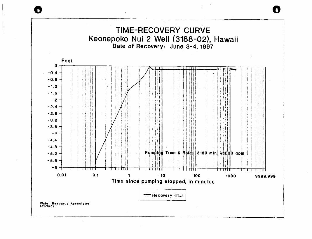
TIME-RECOVERY CURVE Keonepoko Nui 2 Well (3188-02), Hawaii
Date of Recovery: June 3-4, 1997
, I; t
! !
i!
! j
, i
0.1
l I
l!
i i ; ~ ; ! . . '!' .
I 1111 ! I: I,
! i j' lIt I ii, , II!
rQ~Pl?1 i I ! I! I! , I, "
I r 11111
i'
I , .! iii
, iii! 1 , Tim1e , ~Tt ~J: 5160
! i II . It! j
i . I I' ! !
1 10 100
~ ! !
mln~ "
Time since pumping stopped, in minutes
- Recovery (ft.)-j
1000
Water Resource Associates 073TRC1
tt
! i i!
;! \
i
i I ! ~
! i l;
9999.999
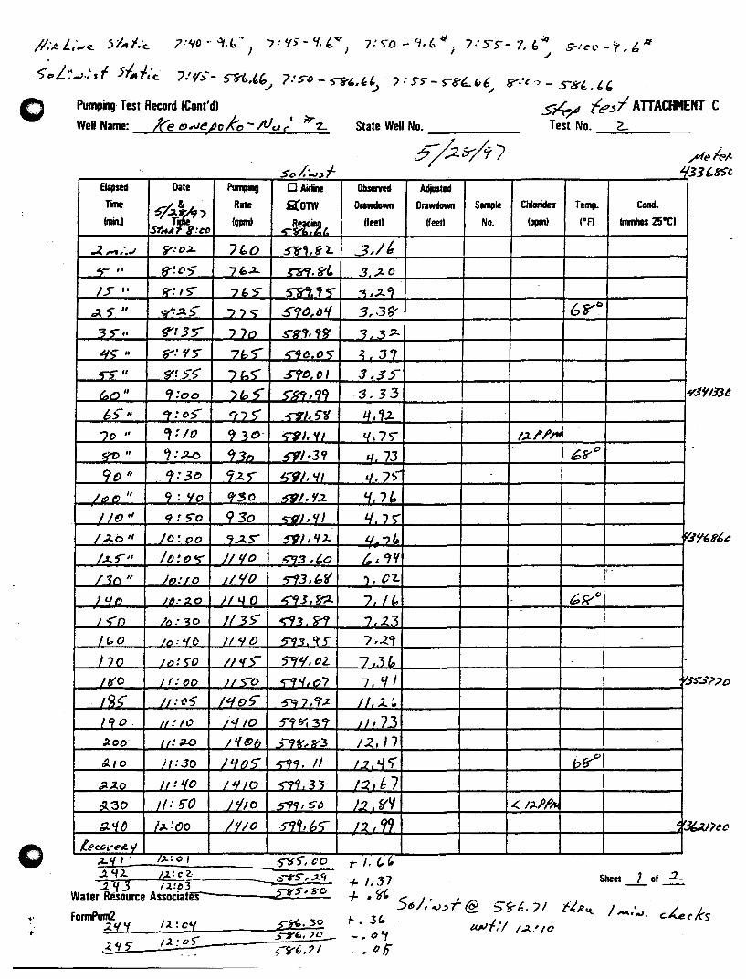
/1:.:..L ..... .z.. 5i,,;:c. ?:¥C·-U,.b~) 7!V>-9.t:,"J', 7:S-0-9,6~i 7:SS-'1,l;~ 9':",-'-1.6,11
5~L:,.,.).:sf 5~t,·c.- ")/'(;- ~i,"'.1 7:s() - S"i"'.'~ -J: S5"- >8'~."6.; ?'C? - S8'£. t.~ o Pumping Test Record (Cont'd) Sl4-./' fe~1 ATTACHMENT C
WeI Name: /(el!J.ve/Joko -;Vu r I I~ z.. - State Well No. Test No. _.=2...~ __ _
$c/''..J~f i{:
EJapsed Date p ..... o Airline Otasefyed Adjusted
rlllle ¢rk' Rate ilOTW Drawdown Orawdown Sample Chlorides Temp. Cond.
(min.) Igpm) RQIIinQ (feet) Ifeetl No. (ppm) IgA (mmhos 2soCI st~ !CD ~fI'"t.1..
.2.,.,.; • ./ ~.·O:A- ")&:.O - 5"8", g t. 3,/1: -..,- " 8': cO; 7 &:..::1- C"H'f.8" 3 ;z. 0
/5 " g-: IS'" 7i>'S ~ <<is'" .~ ,;1..' ~ ~ " .v:.:1.~ ."c; S"'lt>, lJ if 3, .38' 68"°
3>" g': 35'" 'JtJ S"g',!lS' 3 3;:t.
q~ It ~.'f5' 7h -;-- ~9().O'> ~.:J1
52' " $'~ 5S" /bS" .5YJ'f) () I 3 15~-
~o" '1:00 )~~ ~~,99 :3. 33
6S' " er .' oS- 975' -r9/,5g l/ , '1.2. 70 ,I ar: 10 , 30- ~/.VI '/.7') I')'I'~'"
ff'C> " ,: ;:z..o ~3b SY/·3? tL 73 68'°
9() " t:t:3C 9.2. " 5"9j, 'fl LI,7>
/ If) f') " 9 : '10 ttso .~/, 'I:z. 'If 7(,
I/O " 9 t S"o 930 ~),CII -'LJS' 1;;1.;:' II }o:"o 9,l.S 59/,'1). 4 . ., Ie rc-/.l..~1f /f):()~ //1{0 S'93,'0 t,. 1'1 /30 " }O:FO 11,/0 5't3d,r ') I ()1-
L'lJ2. 1~.·;2.0 LL"'lO 5tt~, fr;2.. 7 "
~~c
I"n /t.): 30 If 3S' ~3 S'1 7.2.3 /(,,0 lo:<{t) 1/4/ {) 5"9!J. ~ 5" /,-Z,
)JO lo:~O II.,S- 5'1'1, t>2. 7,.3 £, - -
ItlO Ir:()O I/~O ~"'.o7 7. if I '.$.
I'J§' jl:~5 L,/o§" :5'''1' "} I cr.z 1/, ..2..~
190 - InlO j'lIO 5"'fS'i 3~ J),73 ).00- II: ;J.O I'f (!)b ~-99f, 8"3 12. J 7 /).10 il: 30 ILJ05' _~,--. II 1.2 &.Ie) bS'''
..;t.2.o 1/ :-1{0 ,qlO ~ 33 1:2,1:7 ~30 1/: ~o ;110 599,50 J2.ffY ~ 1~;jJlI<
~..,o il-:~o 1'110 .S'9Q, 6<;- 11. 1 'fI .0=
o {ecJ;j,','- t/ .z..tJ, , j:Lt 0' :$'T{', () 0 rl. (,.(, .
"t.
.1 'i 1.. 1.2.· c" _-__ ~"-!'S, .1<", .2.'(J 1.2!~3 '
Water Resource Associates-----xr~.::..5.:.;, !r::..;u::..
FonnPum2 ~2~~~¥ ____ ~/~~:~cL¥--------~£~~7·~3~O - .:>-:rl" 7(;J_ ,1.. l.f £ /2.:0)
/- 1.:37 Sheet _, of :L
+·~5 J. -..L 6/, ' •. UT @ S-S"6. ,,)1 t4~~ /. / L
, - • ..J. c.1\.e. (' K~ 1-. 3... ~,A)f.·1 /.;l..' 10 -.0'1 _ • 0.li

o
o
STEP DRAWDOWN CURVE Keonepoko Nui 2 Well (3188-02), Hawaii
Date of Test: May 28, 1997
Drawdown, in ft. O~--------------------------------------.
-2 ----r-~~-m--- -....... ------------- .. )
930 gpm
- 4 ~-------------------------~---- ------------------------ --;..------------------------------------------------------------------------------------------------
- 6 ---~-----,-~------------- ----~~~-----
- 8 -------------------------------.-----------------------------------.---------- ------------------------------------------------ ---------------
- 1 0 ------------------------------------,------------------------ - -- -- ----- --- ---------------------------
- 1 2 ------------------------------------------------------------- ------------------------------------------------------------------------------------------------------ --L:~~: -14~------~------~------~------~----~
o 50 100 150 200
Time Since Pumping Started, in minutes
Water Resource Assoclste. 0738DC1
-Drawdown
250

0 OTTO SCALE
J- COUPliNG WOH PWG B.£VATION AT TOP
~ • srm PlATE f OF CASING ~oS.5S mSL
WB..DED TO CASING f GROUND £L£V. "03· ... , "'SL
I 16- CASING
23"DIA ~
~ :s .. ;:<: c til GROUTED 11"\
CS ~ 11"\
ANNULUS § Q .. 10' GROUT ..... <::)
Sl-J ~
~ tc') 10' GROUT <:)
~ c::i 2 SAND <:)
~ .;,,: 2 FINE AGGREGATE .~ • <0 2 COURSE JCGR£GATE --
~ ~ e:. .. ~. Q <= ~ ~
ttl
<= \0 , ~ E ... ~ ~ g (i:i t5 -0 ~ ~ ~
CASING el t-;: GUIDES ..,;;;:
~ ~ ~ ~
BarroN OF BOTTOM OF WELL
KEONEPOKO-NUl2 EXPLORATORY WELL (WELL NO. 3188-(2) PUNA, HAWAII
T.M.K.: 3RD DIV. 1-S-08:POR. 1
As-built sectional drawing of the well. Drilling Completed: May 5, 1997
Drilling Contractor: Water Resources Intemationallnc.

STATE OF HAWAII. .@ QUADRANGLE LOCATION
REFERENCE: U.S.G.S. QUADRANGLE MAP; PAHOA NORTH. HAWAII
PROJECT LOCATION EXISTING KEONEPOKO WELL AND RESERVOIR SITE
DEPARTMENT OF HAWAIIAN HOME lJ\NDS KEONEPOKO-NUI 2 EXPLORATORY WELL
PUNA, HAWAII LOCATION MAP
SCALE: 1 .IN. = 2000 FT.

..
~I D ....
1U~20·
fJQ~ ~ FUTURE FENCE AT=- PROPERTY LINE C NOTE: i CtJN1RNJ1OR SH4U. APPLY AND PAY ii RJR AlL PERIII7S. THE ClMIISSDI li ON IH7ER REStJlJRC£ MWNBIEIIT ~ APPtX:A71ON FDR lEU txJNSIRIJCI10N z PERJIT HAS BEEN FlED Bf DIlL. &: AND TO BE SfGNE/) BY tXJN11W11lJR. m ci II)
~
Is:t I"/:,.. . '""\"",.~
~~.s ~_. ~\1a,t~
BE1IfEN RESSMlR a AND FENCE FOR II)CE$S lD IflOPOSED ItEU
SIT~ PLAN l/JC411ON. KEONEPOKO WELL AND RESERVOIR SITE
. ""~I 3b~ ~...1> :i~a ~\1..~
~I~IQ
2
i§ Q o
.Qj!
~I ~
'~ I<="· &.:
/
SCALE: 1-·40' N'PRrHm:/lj//'YJ), p'i,A, I DEPARTUENT OF HAWAIlAN HOME lANDS ;Vt<:{/~ U • KEONEPOKO-NUI 2 EXPLORATORY WEll
DEPT. Of' WATER SUPPLY COUNTY OF W.WAlI
DATE PUNA. HAWAII

o
APPENDIXB
RESULTS OF DRILLING AND TESTING
o

o
RESULTS OF DRILLING & TESTING
Keonepoko Nui Well 2 (3188-02) Puna, Hawaii
Prepared for
ENGINEERS SURVEYORS HAWAU, INC. Honolulu, Hawaii
Prepared by
WATER RESOURCE ASSOCIATES 1188 Bishop Street, Suite 1708
Honolulu, Hawaii 96813
Honolulu, Hawaii October 1997

o "
CONTENTS
Purpose and Description of ,Well . . . 0 0 0 0 • • 0 0 • • 0 0 0 • 0 • 0 • • • • • • : • 0 0 •
Geology- ............................................... . Hydrolo~ .............................................. .
1 1 1
Step-Dra.wdo'Wll Test ...... ". . . . . . . . . . . . . . . . . . . . . . . . . . . . . . . . . 2 Hydraulic Conductivity ................................. 2 Well Efficiency ........ . . . . . . . . . . . . . . . . . . . . . . . . . . . . . . 2 TraJlSmissivity ....................... . . . . . . . . . . . . . . . . 2
Constant Rate Test ................. 0 0 0 •• 0 0 0 0 •• '0 ••• 0 ••••• 0 0 0' 2
I Effect on Existing Well 0 0 0 0 0 0 • 0 0 0 0 0 0 0 0 0 0 0 0 • • • • • 0 0 • 0 • 0 0 • 0 3
Recovery Test ............... ~ . . .'. . . . . . . . . . . . . . . . . . . . . . . . . 3 Water Quality 0 0 0 • • 0 0 0 • 0 0 0 0 0 • 0 • 0 • • 0 0 • • 0 • 0 0 0 • 0 • 0 • 0 • • • • • • • • • 3
Chloride Content .. 0 • • • 0 0 • 0 • • 0 • • 0 • • • • 0 • • 0 0 • • • 0 • • • • • • • 0 3 Bacterial ........................................... 3 Organics and Me-ta.ls .•••••••.• .. . • • • • • • . . . • . • • • • • • • . • • . .
SUlDID.8lY' • • • • • • • • • • • • • • • • • • • • • • • • • • . • • • • ". • • • • • • • . • • • • • • • Permanent Pump Recommendation ...........:...................
Appendix A. Calculation of Hydraulic Conductivity, K B. Pumping Test Record Co Aecos Report of Microbiological Results D. Brookside Analysis Report E. EoL. Pacific Laboratory Report
Fiaure
1 2
.3 4 5 6 7 8
FIGURES
Regional Water Development Plan As-Built Section of Well Hydrolo~ Map Step Dra.wdown Curve Pumping Rate vs Dra.wdo'Wll Curve S/Q Curve Time-Drawdown Curve Time-Recovery Curve
ii
3 4 4
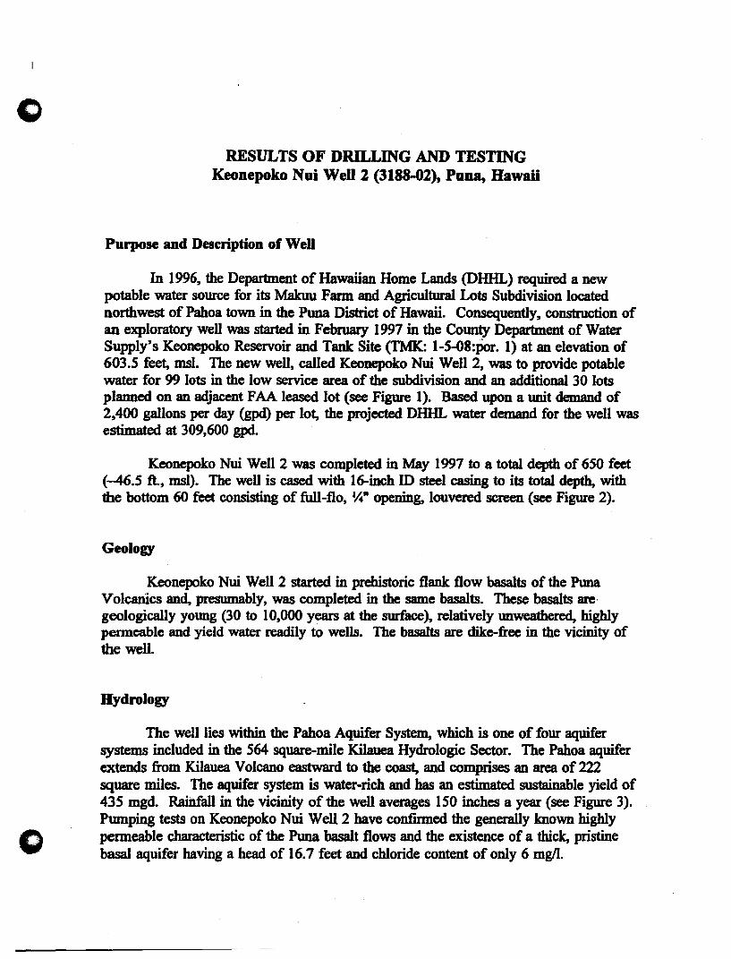
c
o
RESULTS OF DRILLING AND TESTING Keonepoko Nui Well 2 (3188-02), Puna, Hawaii
Purpose and Description of Well
In 1996, the Department of Hawaiian Home Lands (DIDa) required a new potable water source for its Makuu Farm and Agricultural Lots Subdivision located northwest of Pahoa town in the Puna District of Hawaii. Consequently, construction of an exploratory well was started in February 1997 in the County Department of Water Supply's Keonepoko Reservoir and Tank Site (TMK: 1-5-08:Por. I) at an elevation of 603.5 feet, msl. The new well, called Keonepoko Nui Well 2, was to provide potable water for 99 lots in the low service area of the subdivision and an additional 30 lots planned on an adjacent FAA leased lot (see Figure 1). Based upon a unit demand of 2,400 gallons per day (gpd) per lot, the projected DHHL water demand for the well was estimated at 309,600 gpd.
Keonepoko Nui Well 2 was completed in May 1997 to a total depth of 650 feet (-46.5 ft., msl). The well is cased with 16-inch ID steel casing to its total depth, with the bottom 60 feet consisting of full-flo, ~" opening, louvered screen (see Figure 2).
Geology
Keonepoko Nui Well 2 started in prehistoric flank flow basalts of the Puna Volcanics and, presumably, was completed in the same basalts. These basalts are· geologically young (30 to 10,000 years at the surface), relatively unweathered, highly permeable and yield water readily to wells. The basalts are dike-free in the vicinity of the well.
Hydrology
The well lies within the Pahoa Aquifer System, which is one of four aquifer systems included in the 564 square-mile Kilauea Hydrologic Sector. The Pahoa aquifer extends from Kilauea Volcano eastward to the coast, and comprises an area of 222 square miles. The aquifer system is water-rich and has an estimated sustainable yield of 435 mgd Rainfall in the vicinity of the well averages 150 inches a year (see Figure 3). Pumping tests on Keonepoko Nui Well 2 have confmned the generally known highly penneable characteristic of the Puna basalt flows and the existence of a thick, pristine basal aquifer having a head of 16.7 feet and chloride content of only 6 mgll.

.~
o Step-DrawdoWD Test
o
On May 28, 1997, a step drawdown test was performed on the well at pumping rates ranging from 765 gpm to 1410 gpm, with corresponding initial drawdowns ranging from approximately 3.3 ft. to 11.3 ft. (see Figure 4). The Pumping Rate vs Drawdown Curve shown in Figure 5 shows initial drawdowns which can be expected in the well for different rates of pumping.
Hydrtlulic Conductivity. The hydraulic conductivity of the aquifer is approximately 1,460 ftJday based on the step drawdown data in Figure 5 and 6 (see calculation in the appendix).
WeB EffICiency. The efficiency of the well is expressed as the quotient of aquifer drawdown (s..) divided by the total drawdown (s.a...) multiplied by 100. The efficiency of Keonepoko Nui Well 2 is approximately 7.7% (100 x 0.36 ft. + 4.7 ~).
TrllllS1llissivity. The transmissivity of the aquifer, as derived from the relationship, T = Kb, is 999,660 ft.2/day (T = 1460 ftJday x 16.7 ft. x 41 ft.).
Constant Rate Test
A S-day constant rate pumping test was performed on Keonepoko Nui Well 2 from May 29 to June 3, ·1997. During the test, drawdown was.measured by airline pressure readings and directly by a scaled sounding probe. The probe data, however, . was considered more accurate and used in all analyses. Figure 7 shows a semi-log timedrawdown plot of the constant rate test data (see Pumping Test Record in appendix). The transmissivity, T, of an aquifer normally can be calculated from the earliest part of a time-drawdown curve, which for the highly permeable aquifer of Keonepoko Nui Well 2, would probably be the first 100 minutes of pumping. Transmissivity values calculated from later parts of the curve may be affected by hydraulic discontinuities in the aquifer and, consequently, may represent less than true aquifer transmissivity. A transmissivity value of 2.9 x 10' gpdIft. was derived from a graphical analysis of the first 100 minutes of the curve in Figure 7. T is calculated from the relationship, T = 2~sx 0 , where Q is the pumping rate and AS is the drawdown per log cycle.
An offset in the observed drawdown occurs between approximate time, t = 900 minutes to t = 2400 minutes (see Figure 7). However, the two shifts in the time drawdown curve occurred between 12:30 am and 1:30 am, raising the suspicion that human error, rather natural occurrence, was likely involved. As can be seen in Figure 7, it is difficult to determine precisely any drawdown trends, but a hydraulic discontinuity in the aquifer probably occurred between t = 900 and t = 1000 minutes. Also, drawdown in the well appears to have reached an equilibrium of approximately 5.7 ft. during the fIfth day of pumping at the rate of 1,000 gpm.
2

1
(>
o
.'
Effect on Existing WeN. An effort was made to determine any effect on the Department of Water Supply's existing Keonepoko Nui Well 1 (3188-01), located in the reservoir site 1,210 feet north of Keonepoko Nui Well 2. Well 1 was used as an observation well by shutting down the pump and monitoring its water levels a week before, after, and during the constant rate test. A study of the water-level charts produced by a standard 7-day chart recorder showed no discernible effects on the water level in Well 1 due to pumping Well 2. In particular, no change or pulse in water level was observed at the start and at th~ end of pumping and, also, no overall decline in water level resulting from the five days of pumping was discernible.
Recovery Test
I The water level in Keonepoko Nui Well 2 was monitored for a period of 24 hours after pumping was stopped. As can be seen in the semi-log plot of the recovery . data in Figure 8, the well recovered almost instantaneously (4 minutes) to within 0.18 feet of beginning static water level, indicating a very good yielding well.
Water Quatity
Chloride Content. The well produced potable water having a stable, Jew;. pristine chloride content of only 6 mg/l throughout the 5 days of pumping at 1,000 gpm (see Appendix, Pumping Test Record). Field tests of chloride content by the driller using a Hach Kit showed approximate values of 10 mg/l. The temperature of the basal water was constant at 68.0 Fahrenheit and its electrical conductivity was 100 micro Siemens per centimeter.
Bacterilll. Bacterial analysis by Aecos laboratory of a water sample taken on June 24, 1997, after careful well disinfection, showed no coliforms present (see Appendix).
Organics tuld MetIIIs. Water samples taken on June 2, 1997 during the last day of the S-day constant rate pumping test were analyzed by Brookside Laboratories and Environmental Laboratory of the Pacific for parameters required by the State Department of Health for new potable water sources (see Appendix). The required suite of metals were tested and found "non-detectable" or within established maximum cOntaminant levels. The required suite of tests for organic compounds were all "nondetectable." Other analytical results, all of which are well within the normal range for basal ground water, include:
Alkalinity: Fluoride: Calcium: Nitrate + Nitrite: Electrical Conductivity:
43.0 mgll 0.23 mgll . 6.1 mgll 0.22 mgll 120 J.1S1cm
3
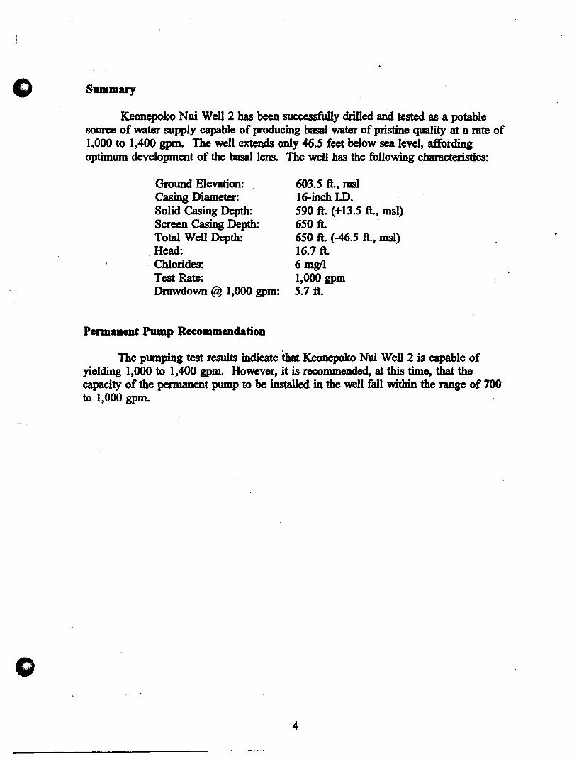
"
o Summary
o
Keonepoko Nui Well 2 has been successfully drilled and tested as a potable source of water supply capable of producing basal water of pristine quality at a rate of 1,000 to 1,400 gpm. The well extends only 46.5 feet below sea level, affording optimum development of the basal lens. The well has the following characteristics:
Ground Elevation: Casing Diameter: Solid Casing Depth: Screen Casing Depth: Total Well Depth: Head: Chlorides: Test Rate: Drawdown @ 1,000 gpm:
Permanent Pump Reeommendation
603.5 ft., IDSI 16-inch I.D. 590 ft. (+13.5 ft., IDSI) 650 ft. 650 ft. (-46.5 ft., IDSJ) 16.7 ft. 6mgll 1,000 gpm 5.7 ft.
The pumping test results indicate that Kconepoko Nui Well 2 is capable of yielding 1,000 to 1,400 gpm. However, it is recommended, at this time, that the capacity of the permanent pump to be installed in the well fall within the nmge of 700 to 1,000 gpm.
4

! w ..
i. I
\
o I mile
I I Sc:alc
LEGEND
• KEONEPOKO NJI WElLS 1 & 2
• PAHOA WElLS 2A & 2B
\\ • MUNICIPAL WATER SERVICE AREA " , \" B PROPOSED WATER DevELOPMENT AREA
® Source and Reservoir Development \\ \ .~
\ .... \ .....
", . \ .
@ Transmission Main Development
Figure 1. Pahoa Area
REGIONAL WATER DEVELOPMENT PLAN (Modified after Fig. 1.9-1, Hawaii County Water Use and Development Plan, Review Draft, 2192

CASING GUIDES
• •
El£VATION AT TOP OF CASING ,-oS.5~ Ift.5L
"--J~IIIYU GROUND B..EV. ~o 3 .+7 ~SL
DIA.
BOTTOM OF WELL
AS-BUILT SECTION
Keonepoko Nui 2 Exploratory Well (3188-02) Puna, Hawaii
As-built sectional dnwiDg of the welL Drilling Completed: May 5, 1m
. DrilliDg Contractor: Water Resources International Inc.
(not to scale)
Figure 2

o Papaikou
o o 12000 ft. I I A
Scale N
Legend: -AD- Median Amual Rainfall in inches .- •. Aquifer System Boundary
A Kaonepoko Nui 2 Well Site Off Well. showing head lilt and chloride ImgIIt
• Raingaga
Pahoa Aquifer System
Water Resource Associates
Figure 3.
HYDROLOGY
Makuu Farmlot Subdivision Pahoa, Hawaii
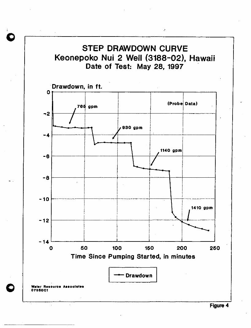
c
o
STEP DRAWDOWN CURVE Keonepoko Nui 2 Well (3188-02), Hawaii
Date of Test: May 28, 1997 .
Drawdown, in ft. O~------~--------~------~--------~-------,
I! I
~2~ __ ~~7_6_~~1 _gp_m ______ ~,I!I.I--------~---(-p-rO-b-e~ID-a-ta-)-----1 I .1930 gpm
"j i . -4 +-. ---
i
I 1140 gpml
- 6 ~-- .---+---
-8~-----~--------i--- ---+----~--+-----~
I 1 0 I--------t--------+---------!l-------I----i------
- I I 1410 gpm
I -12 I--------+---------i------r----"""d-+-------
i
-14L--------L--------~------~--------~------~
o 50 100 150 200
Time Since Pumping Started, in minutes
Wet.r A •• oure. A •• oelet •• 0738DC1
-Drawdown
250
Figure 4
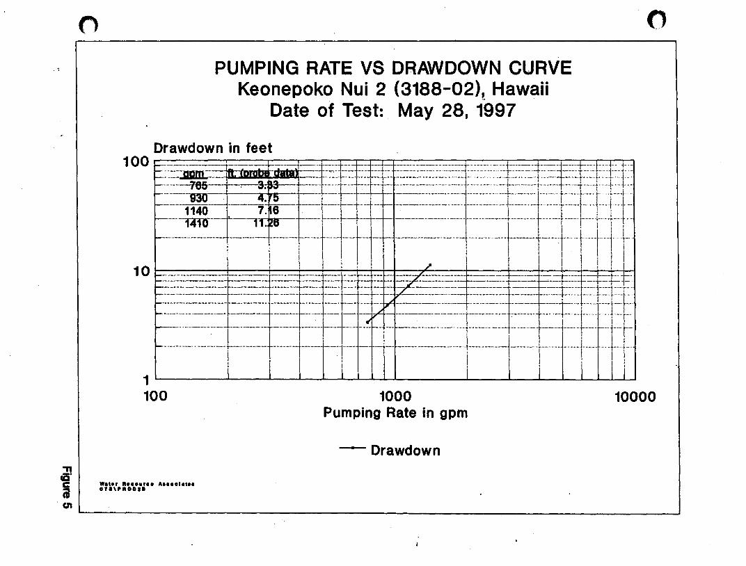
" ca' e i Con
PUMPING RATE VS DRAWDOWN CURVE Keonepoko Nui 2 (3188-02)~ Hawaii
Date of Test:. May 28, 1997
Drawdown in feet
---1- I ---I+~ --------I-------t-+-.r il1-10 I ! \ I I !
I I. I I I 1~----~--~~--~~~~----~~~~~~~~~
o
100 1000 10000
W.,.r R ..... r •• A •••• '., •• """RDD'.
Pumping Rate in gpm
-Drawdown

o
"T1 cC' e iii
s/Q
s/Q Curve Keonepoko Nui 2 Well (3188-02)
Date: May 28, ·1997
o
0.007--------~------~------~------~------~------~
0.006
I . o .00 5 ... ·· ... -················ ... -··-·· ... _-··-·-·_·1 -.............................. - .......... -....................................... -....... ----..... - ......... ---........ - ........... -.......... ·· ... -· ......... ·-·-···-· ... ·-·-... -·-········ ... ······-·t··-·-·- .. , ........ -. - .... -:-.-..... 1-............ - ........................ - ......... --•.. - ......... - ......... .
I C _ ,OO6S2 - ,0039 o . 0 0 4 ...... -.............. _ .................... -.... -..... -................. -...... --.............................. -...... -.............. , ......................... -...... -................ -······-t ... ···· ... ·· ... ··· .................... ............................ ... . ....... ......... ..-.................. -.... -.. _ ............ _._ .... _ .. _ ... ..1 20.0 ................... -. I " - .00613 ! I~
0.003 ................... _ .... ___ ............... _ ........ ___ .................... _ ... _ ........................... _ ...... _ ............. __ ... __ ~. ,.LLl~ .. _ ......... __ _
0.002
0.001
O~------~------~------~------~------~~----~
o 200
Wat.r ft •• ouro. A .. oolat .. 07a,aQI
400 600 800 Pumping Rate, in gpm
1000 1200
"
Q.~------------------------------------------------------------~
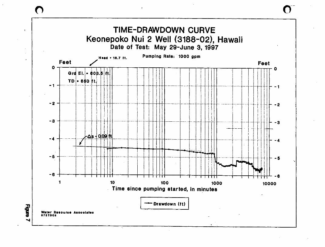
Feet
TIME-DRAWDOWN CURVE Keonepoko .Nui 2 Well (3188-02), Hawaii
Date of Test: May 29-June 3, 1997
Head • 16.7 ft. Pumping Rate: 1000 gpm
/' Feet 0~--~~-r~~--~~-r~~--'-~~~~--~~-r~1I0
GrJ E"I" .oHI'H I II I I I I II I II I I ! II I -1 ___ TDI" Ttnl- t--iiif-r 1---[---1-rill 1-/- t-:-lti-t
1l ~ -1
-2 - -..... " . ···+-t ,··t + ·f· r'--'" .... -! .. ·····t---·j-··-rt··\- i-" ...... -- .... -. -.-.' j-- '" . t-·tJr I - -- - - til + r ,II ~ -2
! I i I ; 'II ! I 'I I I II! I :1: II II: i i ! I Ii!' ! i I j I 1 I I I ! :
-3 - - i!--r- -Ii - -- -- i --1,- 1,--r- ,- -- -- --T --- -'- ---- --+-'11111+: -3
I I 'I . ' I, I I
I I, I _ .... -. -. -- -1,-- .- "'f,'" '-'j' ---1---t ... - .} r-'--' .----. - .-. --. ..1. ____ . ...... -. i_.1 . -.. -" . j... 1- 'f,'"'+ Ii" j I t - -4 -4 _.
.- -' . I i I ! Ii \
- 6 - ---~--- - ---,'1---+-+-+-----1-1- -----'- -~~ _lrl~I_IJli j ~ -6
I 1/ , ii' i l' II .-- I~ I ~~ .. , Ji I I i I I 1 I--6+---+I-+,-rrH~In---+I-+I-rrH,+H---+I-+,-rHH+H-I--+,-+,~,~H4+L_6
1
Water R •• ouro. Anoolat •• 07lTDCa
10 100 1000 10000 . Time since pumping started, in minutes
I - Drawdown lit) ,

Feet
TIME-RECOVERY CURVE Keonepoko Nui 2 Well (3188-0_2), Hawaii
Date of Recovery: June 3-4, 1997
= ::: = ., -, .1:J ~iW=~-k + :'::,~ -:-~~: : -t ·~~·l-'\ . :'J1,-_:. ~~ .1 jl W
= :::. I---r-tb-Lrrt ------., r--T -"'. --, -l'· fl-pl -2
-2.4
-2.8 - - ....... f·_······+--+ ., tl-- ,,-- t"""'r '-r lll'- ._ .... "" .-.-- .". ." .-." ,,_. "" ... "····""1"· 1'1' .. " ... "."',' ["""'1'- 1--"" j ['-rt
= ::: = ,'~-~ =+t" " ~: ~t~ll! ::)\ ~'j~~,: '-t:t )-: :' ,:\ :~II :'-~-,l:1 f 'J 11 rj: -4 -, ,,, .. I """-"""1" d'"r ".,,' r .. ,!, 1 tool "It '"." ,j"" 1"'" "' '-l- t,l ."" . t· t ! L I "." ".' 1'""1 I j' d
I ! 1 ! I I I • II! i ! I I I ' I I! I. I r : i'
-4.4 - """-"""'1" 't-' '['-j"+t' "I "" "."" t, it ""j-"t, "1 j It ._"'"." j' ,," "r "'j" t"lll t I'" "r ! i 11.1 t', 'Jt' t· "j" tIl rr t'l
=::: =trtrrI r,i ': ill Ij ~..JIll,;nH~~I~' ~at .. h2~H4I'~' o~-~ tp~, rill [! I I J I! ~ Ii! : : II! i ',I ! I I . 1 i I !: I r i j I I I ! :
-5.6 - - ". "I· .. "I'''""" "rl j " ... "" i ' '; j t" tIl' "'''''''' I "" I· f 1" rHo '" .l... L ! j I lJ t' ". I . I" " I r d !. iii I Ii! i : Ii., I I I I I I! I I : ! I III I!. I Iii
-6 I I I I I II I I I I I III I I I 1 I II I I I I I III I I I I I III
0.1
Wat.r R •• ouro. A •• oolat •• 07aTRC1
1 10 100 1000 10000 Time since pumping stopped, in minutes
I --- Recovery (It.) I
! .'
C
APPENDIX
o . .

o
"
CALCULATION OF HYDRAULIC CONDUCTIVITY, K
Keonepoko Nui 2 Well (3188-02), Hawaii
From S/Q Curve:
B = .00039 C = 5.1 X 10⁻⁶
statal = Saq = Swell - BQ+C<l
Saq = BQ = .00039 x 930 = 0.36 ft.
Swell = C<l = 5.1 x 10-6 x 0.85 X 10' = 4.34 ft.
ck: stotal = 0.36 + 4.34 = 4.7 ft. AS 4.75 obs'd
rd = i~: x ~ = 1.0 ft.
D where 0 In(d + rd>
= 64.2
= 4.16 ft. In(64.2 + 1)
= active length of well = 16.7 + 47.5 = 64.2 ft.
K = 930 gpm x (1440 + 7.48) = 1.79 x lOS ft3/d
=
= 1456 ftld
AppendxA

o
o
PUMPING TEST RECORD ."
Well Name Keonepoko Nui #2 State Well No. 3188-02)
Test No • ..,:L May 29,1997
Projed ______________________ __ Island Hawaii
DEPTHS, in It. (Below Ground Surface):
Solid Csg:-Rn.. Perforated Csg: 851 Total Depth: 651 Depth to Water: 586,70·
*Remarks: Ref, Top of Pad
TEST PUMP: Type: 10" Une Shaft Intake Elev: -29,53
D IS CHARGE MEASUREMENT:
aa,., 0111 rlBll a (nin.t r ...
i 5129197: I
! 8:30 l1li
I 9:00
1 9-.20 \
,
9-.30 l1li i
8 9:38
15 9:45
20 9:50
30 10:00
40 10:10
50 10:20
160 10-.30
90 11:00
20 11:30
80 12:30 pm
40 1:30 ,.., 2:30
so 3:30
.20 4:30
Jao 5:30
!4O &.30
Watar Resource Associates
PUMPTR.RES
.-
8 Flowmeter
....... R.ta
fgpml
0
0
0
Start PIInp
1014
1007
1008
1002
1007
1005
1005
1005
1005
1005
1005
. 1010
1010
1000
1005
1005
ELEVAnONS, in ft. (Mean S •• Level): Ground Surface: 603,47 Top of casing: Rotary Table: ____ _
Bot of Solid Csg: 12.47 Bot of Perf. Csg: -47.53
Bot of Well: -47,53 Static Water Level: +16,n DRAWDOWN MEASUREMENT:
o Manometer 0 Pressure Gage 8 Elect. Probe o other
0 __ .
IJrawdDMt Chlorides T...,. Cond.
IfaetJ (ppmJ (of) (poNs 25°C'
0
0
o (DTW-586.n
4.55
4.49
4.50 88.5
4.52 68
4.54
4,54
4.55
4.54
4.56
4.60
4.81
4.67 68
4.69
4.12
4.72
4.74
Appencix B Sheet 1 of 7
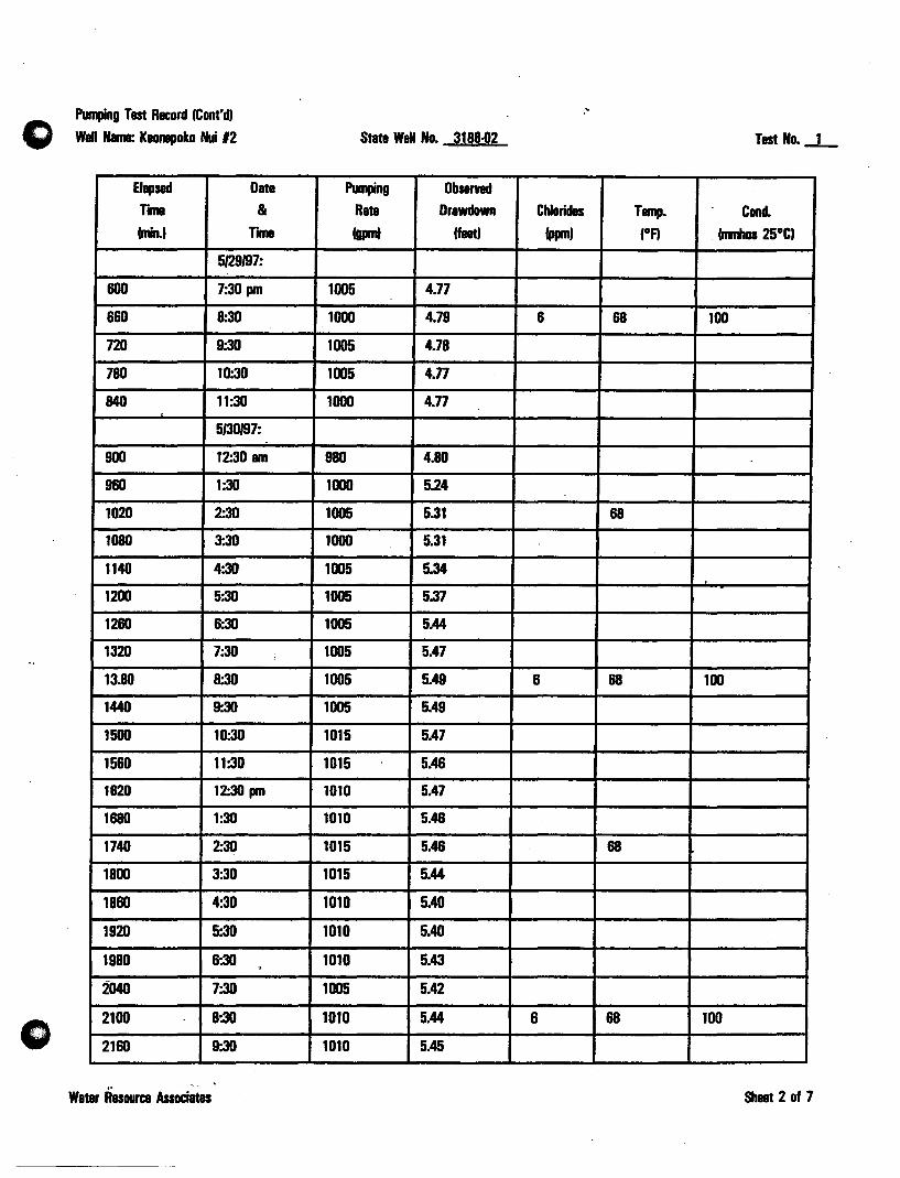
o
Pumping Tast Record (Cont'd)
Well Nama: KlOnepoko Nui 12
Elapsed Date TI11'II &
(min.I THne
5129197:
600 7:30 pm
660 8:30
720 9:30
780 10:30
840 11:30
5/30197:
900 12:30 am
960 1:30
1020 2:30
1080 3:30
1140 4:30
1200 5:30
1260 6:30
1320 7:30 :
13.80 8:30
1440 9:30
1500 10:30
1560 11:30
1620 12:30 pm
1680 1:30
1740 2:30
1800 3:30
1860 4:30
1920 5'.30
1980 6:30 . 2040 7:30
2100 8:30
2160 9:30
Water Resource Associates
.~
State Well No. 3188=02 Test No.~
Pumping Db ..... Rate Drawdown Chlorides Tamp. Cond. (- (feet) (ppm) (OA (mmhos 25°CI
1005 4.77
1000 4.79 6 68 100
1005 4.78
1005 4.n 1000 4.n
980 4.80
1000 5.24
1005 5.31 68
1000 5.31
1005 5.34
1005 5.37
1005 5.44
1005 5.47
1005 5.49 6 68 100
1005 5.49
1015 5.47
1015 5.46
1010 5.47
1010 5.46
1015 5.46 68
1015 5.44
1010 5.40
1010 5.40
1010 5.43
1005 5.42
1010 5.44 6 68 100
1010 5.45
Sheet 2 of 7

o
PUII1Jing Test Record (CDf!I'd) Well Nama: KlDnapoko Nui 12
Elapsed Date
TIII18 &
(nin.) Tn
5130197:
2220 10:30
2280 11:30
5/31197:
2340 12:30 am
2400 1:30
2460 2:30
2520 3:30
2580 4:30
2640 5:30
2700 6:30
2760 7:30
2820 8:30
2880 9:30
2940 10:30
3000 11:30
3060 12:30 pm
3120 1:30
3180 2:30
3240 3:30
3300 4:30
3360 5:30
3420 6:30
3480 7:30
3540 8:30
3600 9:30
3660 10:30
3720 11:30
,. Water Resource Associates
.-
.'
State Well No. 3188-02 Test No._l_
PlInping Obsenad
Rate Drawdown Chlorides Tamp. Condo (gpm) (feet) (ppm) (DA . (mmhos 25DC)
1010 5.45
1010 5.47
1005 5A7
1010 5.18
1010 5.18 68
1010 5.19
1010 5.20
1010 5.23
. 1010 5.24
1005 5.24
1005 5.21 6 68 100
1010 5.23
1010 5.24
1010 5.25
1010 5.23
1005 5.21
1010 5.21 68
1015 5.22
1015 5.21
1015 5.23
1015 5.22
1010 5.24
1010 5.23 5 68 100
1010 5.23
1010 5.30
1005 5.29
Sheet 3 of 7

Pun1Jing T~ Record (Cont'd)
Wall Nama: Kaonapoko Nui 12
Elapsed Date
TIme &
(ninJ TIII18
611197:
3780 12:30 am
3840 1:30
3900 2:30
3960 3:30
4020 4:30
4080 5:30
4140 6:30
4200 7:30
4260 8:30
4320 9:30
4380 10:30
444D 11:30
45DD 12:30 pm
4560 1:30
4620 2:30
4680 3:30
4740 4:30
4800 5:30
4860 6:30
4920 7:30
4980 8:30
5040 9-.30
5100 10:30
5160 11:30
612197:
5220 12:30 am
5280 1:30
5340 2:30
'" Water Resource Associates
,
0'
State Wall No. 3188-02 Test No._1_
PIIr1Iing ObS8l'Ylld
Rate Drawdown Chlorides T ...... Cond. (gprnt (feet) (ppm) (DA . (mmhos 25DC)
1010 5.29
1005 5.3D 68
1005 5.31
1015 5.25
1010 5.31
1015 5.30
1010 5.35
1005 5.34 68
1010 5.35 5 100
1010 5.35
1005 5.35 . 1005 5.36
1010 5.35
1010 5.33 68
1005 5.35
1010 5.33
1000 5.48
1000 5.48
1000 5.48
1000 5.50 68
1000 5.54 5 100
1000 5.59
1000 5.60
1000 5.60
1000 5.60 68
1000 5.60
1000 5.61
Sheet 4 of 7
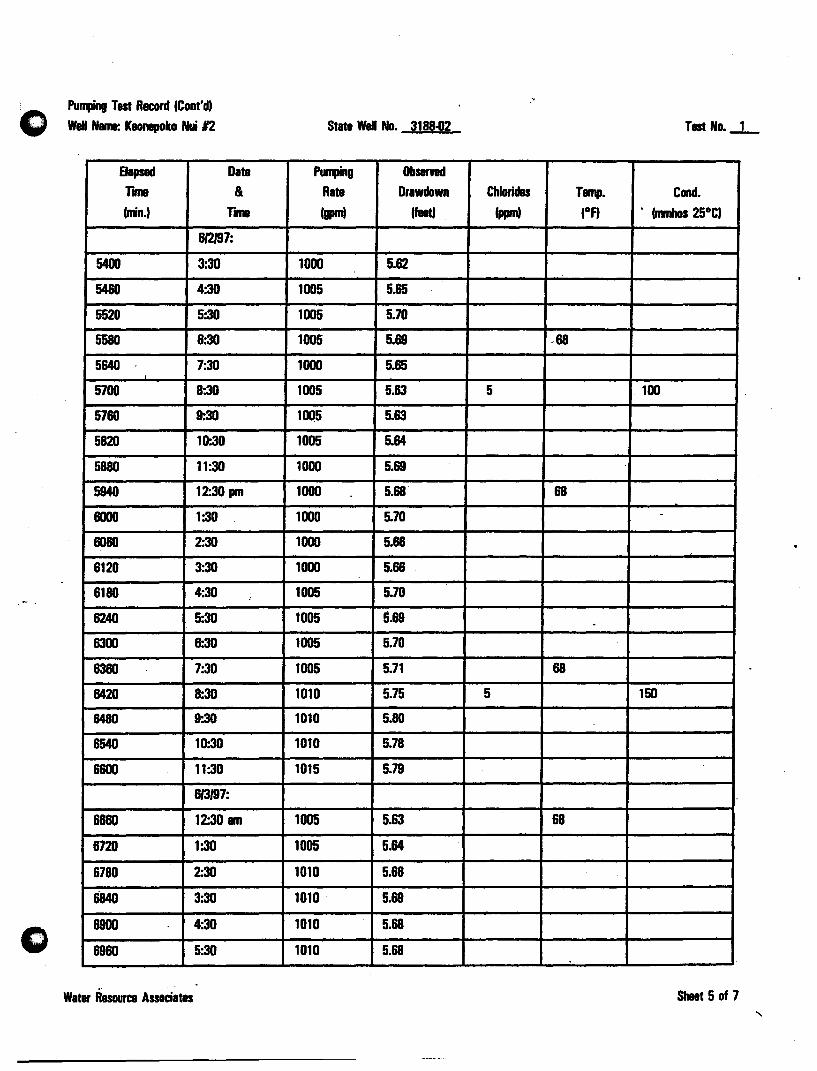
Purqing Test Record (Cont'd)
Well Name: Keonapolco Nui 12
Elapsed Date
TIne &
(nin.) Tn
612/97:
5400 3:30
5460 4:30
5520 5:30
5580 6:30
5640 7:30
5700 8:30
5760 9:30
5820 10-.30
5880 11:30
5940 12:30 pm
6000 1:30
6060 2:30
6120 3:30
6180 4:30 ,
6240 5:30
6300 6:30
6360 7:30
6420 8:30
6480 9:30
6540 10:30
6600 11:30
6/3197:
6660 12:30 am
6720 1:30
6780 2:30
6840 3:30
6900 4:30
6960 5:30
Water RBSOuree Associates
State Well No. 3188.1J2 Tast No.-1-
".,.g Obsarnd
Rate Orawdown Chlorides Tamp. Conet. (. (flat)
(. (OA • (nJnhos 25°C)
1000 5.62
1005 5.85
1005 5.70
1005 5.69 .68
1000 5.65
1005 5.63 5 100
1005 5.63
1005 5.64
1000 5.69
1000 5.68" 68
1000 5.70 -
1000 5.68
1000 5.68
1005 5.70
1005 5.69
1005 5.70
1005 5.71 68
1010 5.75 5 150
1010 5.80
1010 5.78
1015 5.79
1005 5.63 68
1005 5.64
1010 5.68
1010 5.69
1010 5.68
1010 5.68
Sheet 5 of 7
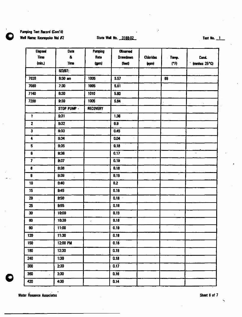
o
o
Punfing Tast Record ICont'd, waU Nama: Kaonepoko Nui 12
Elapsed Data
Tnna &
lnin.' TIIIII
813197:
7020 6:30 am
7080 7:30
7140 8:30
7200 9:30
STOP PUMP-
1 9:31
2 9:32
3 9:33
4 9:34
5 9:35
6 9:36
7 9-.37
8 9:38
9 9:39 ..
10 9:40
15 9:45
20 9:50
25 9:55
30 10:00
60 10:30
90 11:00
120 11:30
150 12:00 PM
180 12:30
240 1:30
300 2:30
360 3:30
420 4:30
Water Resource Associates
"
State Well No. 3188-02 Tast No • ..l-
PlIIIPing Obsamd Rata Orawdown Chlorides . Tamp. Condo
I!PII' Ifaat) Ippm) lOA . fnmhos 25°C'
1005 5.57 68
1005 5.61
1010 5.60
1005 5.64
RECOVERY
1.36
0.9
OAS
0.04
0.18
0.17 -
0.19
0.18
0.19
0.2
0.18
0.18
0.18
0.19
0' 0.18
0.19
0.18
0.18
0.18
0.18
0.17
0.16
0.14 0
Shill 6 of 7
"
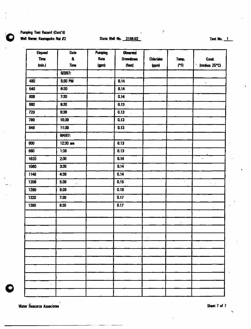
Ptlnping Test Record (Cont'd,
Well Nama: Keonepoko Nui 12
Elapsed Date
rll1ll &
(nin.' r ... 813/97:
480 5:30 PM
540 6:30
600 7:30
660 8:30
720 9-.30
780 10:30
840 11:30
614197:
900 12:30 am
960 1:30
1020 2:30
1080 3:30
1140 4:30
1200 5:30 :
1260 &-.30
1320 7:30
1380 8:30
Water Resource Associates
State Wei No. -3188.(J2 Test No. _1 _
~ Observed Rata orawdown Chlorides T ...... Cond.
(p' (feet) (ppm) (Df) (nJmos 25DC,
0.14
0.14
0.14
0.13 .-
0.13
0.13
0.13
0.13
0.13 . 0.14 .
0.14
0.14
0.15
0.1&
0.17
0.17
-
Sheet 7 of 7
"

r - 1Ri ~ fa [ ~ Wi ~ [D) JUL 3 ~997 AECOS "
970 rI. Kalabeo Avenue. SuIte C300 • KaIlua. Hawaii 96734 Telephone: (808) 254-5884
CUENT: Engineer Surveyors Hawaii
ATI'ENTION: Eric Hoe
FILENo.: REPORT DATE:
PAGE:
846 06/27/97
1 of 1
AECOS REPORT OF MICROBIOLOGICAL RESULTS
SAMPLE TYPE: well water AECOS LOG No.: 10703
DAtE SAMPLED: 06/24/97 METHOD SM 9221B DATE/11ME RECEIVED: .06/24/97@1335 SAMPLER: DanLum TEMPERA1lJRE CONTROl: 1.3° C MATRIX: water OILORINE RESIDUAl:
ADalysls Date/Time: 06/24/97@1400 Analyst: R. Douglas
ANALYTE Total Coliform
(UNITS) (present/Absent)
SAMPLE 10 3 "A" KPN Well 1#2 06124197 Absent
0900
NOTES:
~, 1. Mello, Laboratory Director Appendx C
BROOKSIDE LABORATORIES, INC. ENVIRONMENTAL & INDUSTRIAl DIVISION
P.o. BOX 456 308 S. MAIN STREET . NEW KNOXVILLE. OH 45871
(419) 753-2448
aNALYSIS ImPORT
We are pleased to submit the following AIIalysJs Report. Please review the data and feel &ee to call us if yoU have questions or need. additional tests and/or tec:huical assistance.
This report shall not be reproduced except in foB and with the written approval &om Brookside Laboratories, Inc.
GENERAL INFORMATION t
Account No : 61690 .Report Submitted To: Verle Heyer
CUent Name: Brewer Environmental Ind. Report No : DE73637
Project Name: Lab Job #E7060206 Report Date: 06117197
Site NamelLocation :
Sample Collected Dr. H. 1;'onaka
Comments: voe·s. SOC's, and metals were analyzed by Environmental Health Laboratories of South Bend. Indiana; Fluoride was analyzed by BU.
ANALYI'ICA,L RESULTS
Analytical results are presented on page 2 lhr.ougb. page S of this report. -
AU11IORI7.EO SIGNATURES
~L ~ ( !lUi ¥1f. ~
Zhilun Xue, Ph.D. Lam V. Ho, Ph.D .• REP,
Senior Chemist Director. EID
Appendx 0

o
BROOKSIDE LABORATORIES, INC. ENVIRONMENTAL & INDUSTRIAL DIVISION
P.o. BOX 456 308 S. MAIN STREET NEW KNOXVILLE, OH 45871
(419) 753·2448
~NALYSIS imPORT
We are pleased to submit the following Analysis Report. Please review the data and feel free to call us if you have questions or need additional tests and/or technical assistance.
This report shall not be reproduced except in full and with the written approval &om Brookside Laboratories, Inc.
GENERAL INFORMATION
Account No : 61690 Report Submitted To: Verle Heyer
Client Name: Brewer Environmental Ind. Report No : DE73637
Project Name: Lab Job #E7060206 Report Date: 06120197
Site NamelLocation :
Sample Collected By: H. Tanaka
Comments: Resubmitting page 4 with Dioxin results. Dioxin results were performed by Core Laboratories in Indianapolis, Indiana.
ANALYI'ICAL RESULTS
Analytical rt:SullS iUe presented on page 2 through page 5 of this report.
Peter A. Coni~s
QAlQC Officer
AUTHORIZED SIGNATURES
Lam V. Ho, Ph.D., REP,
Director. EID
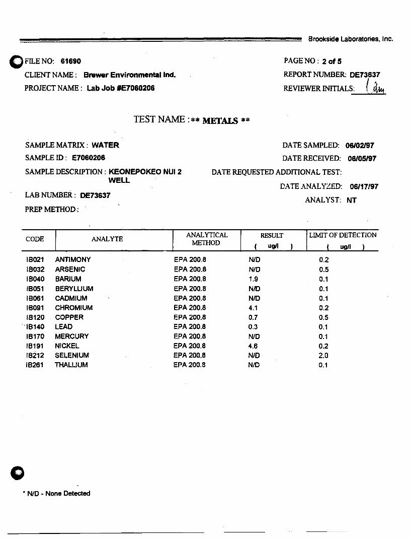
() FILE NO: 61690
CLIENT NAME : Brewer Environmental Ind.
PROJECT NAME: Lab Job tlE7060206
Brookside Laboratories, Inc.
PAGE NO : 20f5
REPORT NUMBER: DE73637
REVIEWER INITIALS: ( ,it",
TEST NAME : ** METALS **
SAMPLE MA TR1X: WATER
SAMPLEID: E7060206
SAMPLE DESCRIPTION: KEONEPOKEO NUl 2 WELL
LAB NUMBER: DE73637
PREPMETHOD-:
DATE SAMPLED: 06/02197
DATE RECEIVED: 06/05/97
DATE REQUESTED ADDITIONAL TEST:
DATE ANALYZED: 06/17197
ANALYST: NT
CODE ANALYTE ANALYTICAL RESULT LIMIT OF DETECTION
METHOD ( ug/I ) ( ug/I )
IB021 ANTIMONY EPA 200.8 NlD 0.2
IB032 ARSENIC EPA 200.8 N/D 0.5
IB040 BARIUM EPA 200.8 1.9 0.1
IB051 BERYLLIUM EPA 200.8 NlD 0.1
IB061 CADMIUM EPA 200.8 N/D 0.1 IB091 CHROMIUM EPA 200.8 4.1 0.2 IB120 COPPER EPA 200.8 0.7 0.5
-IB140 LEAD EPA 200.8 0.3 0.1
IB170 MERCURY EPA 200.8 N/D 0.1 IB191 NICKEL EPA 200.8 4.6 0.2 IB212 SELENIUM EPA 200.8 N/D 2.0 IB261 THALUUM EPA 200.8 N/D 0.1
* NlD - None Detected

FILE NO: 61690 o CLIENT NAME: Brewer Environmental Ind.
PROJECT NAME: Lab Job tlE7060206
Brookside Laboratories. Inc.
PAGE NO : 3 of 5
REPORT NUMBER: OE73637 I " REVIEWER INITIALS: Ldta
TEST NAME: ** GENERAL ANAL YSIS **
SAMPLE MATRIX: WATER
SAMPLE ID: E7060206
SAMPLE DESCRIPTION: KEONEPOKE NUl 2 WELL
LAB NUMBER: OE73637
ANALYlE PREP ANALYTICAL METHOD METHOD
ALKALINITY - TOTAL SM2320B
CYANIDE - TOTAL EPA 335.4
CONDUCTIVITY . EPA2510B
FLUORIDE SM4500C
CALCIUM EPA3111 B
PENTACHLOROPHENOL EPA 515.1
PICLORAM EPA 515.1
01 (2-ETHYLHEXYL) ADIPATE EPA 525.2
ALDICARB EPA 531.1
ALDICARB SULFONE EPA S31.1
ALDICARB SULFOXIDE EPAS31.1
OXAMYL (VYDATE) EPAS31.1
DIQUAT EPA S49.1
ENDOTHALL EPA 548.1
01 (2-ETHYLHEXYL) PHTHALATE EPA 525.2
BENZO (a) PYRENE EPA 52S.2
HEXACHLOROBENZENE EPA 52S.2
HEXACHLOROCYCLOPENTADIEN EPAS2S.2
G-BHC (LINDANE) EPA 525.2
CHLORDANE EPA 50S
ENDRIN EPA 52S.2
HEPTACHLOR EPAS25.2
HEPTACHLOR EPOXIDE EPA 52S.2
PCB-AROCHLOR 1016 EPA 50S
PCB-AROCHLOR 1221 EPASOS
OPCB-AROCHLOR 1232 EPASOS
PCB-AROCHLOR 1242 EPASOS
• NID - None Detected
DArE ANALYZED
06109/97
06/12197
06109197
06/17197
06117197
06/09/97
06109/97
06/10197
06109/97
06/09/97
06109197
06/09197
06/10/97
06/09197
06110197
06110197
06110/97
06110197
06110/97
06/10/97
06/10m7
06110197
06/10/97
06/10/97
06110197
06110/97
06/10/97
DATE SAMPLED: 06/02197
DA TE RECEIVED: 06105/97
RESULT LIMlTOF DETECTION
43.0 mgJI 1.0 mgJI
N/D 0.02 mg/l
120 umhoslcm 0.1 umhoslcm
0.23 mgJI 0.20 mgJI
6.1 mgJI 0.1 mgJI
NIO 0.04 ugJI
NIO -0.1 ugJI
NIO 0.6 ugJI
NIO O.S ug/l
NIO 0.4 ugJI
NIO O.S ugJI
N/D 1.0 ug/l
NlD 0.4 ug/l
NID 9.0 ugJI
NIO 0.6 ugJI
NIO 0.02 ugll
N/O 0.1 ugJI
NIO 0.1 ugJI
N/O 0.02 ug/l
N/D 0.2 ug/l--
N/D 0.01 ug/J
NIO 0.04 ug/J
NIO 0.02 ugJI
NIO 0.8 ug/l
N/D 2.0 ug/l
NIO O.S ug/l
N/D 0.3 ugll
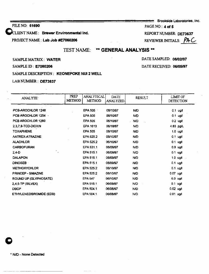
FILE NO: 61690
()cLIENT NAME: Brewer Environmental Ind.
PROJECT NAME: Lab Job 'E7060206
Brookside Laboratories, Inc.
PAGE NO : 40f5
REPORT NUMBER: DE73637
REVIEWER INITIALS: fTt c TEST NAME: ** GENERAL ANALYSIS **
SAMPLEMATRIX: WATER
SAMPLE ID: E7060206
SAMPLE DESCRIPTION: KEONEPOKE NUl 2 WELL
LAB NUMBER: DE73637
'1 ANALYTE- PREP - ANALYTICAL DATE
METHOD METHOD ANAL YZED
PCB-AROCHLOR 1248 EPA505 - 06110197
PCB AROCHLOR 1254 EPA 505 06110197
PCB AROCHLOR 1260 EPA 505 06/10197
2,3,7,8-TCD-DIOXIN EPA 1613 06118197
TOXAPHENE EPA 505 06/10197
AATREX-ATRAZINE EPA 525.2 06/10197
ALACHLOR EPA 525.2 06/10197
CARBOFURAN EPA 531.1 06/09197
2,4-0 EPA 515.1 06/09/97
DALAPON EPA 515.1 06/09197
DINOSEB EPA 515.1 06/09197
METHOXYCHLOR EPA 525.2 06110197
PRINCEP - SIMAZINE EPA 525.2 06/10197
ROUND UP (GLYPHOSA TE) EPA 547 06110197
2,4,5-TP (SILVEX) EPA 515.1 06/09/97
DBCP EPA 504.1 06/06197
ETHYLENEDIBROMIDE (EDB) EPA 504.1 06/06/97
-0 * NID - None Detected
DA IE SAMPLED: 06/02197
DA IE RECEIVED: 06/05/97
, RESULT I LIMIT OF
DETECTION
NID 0.1 ugJI
NID 0.1 ugJI
NID 0.2 ugIJ
NID 4.83 pgJI.
NID 1.0 ugJI
NID 0.1 ugJI
NID 0.1 ugJI
NID 0.9 ugJI
NID 0.1 ugJI
NID 1.0 ugJI
NID 0.1 ugJI
NID 0.1 ugJI
NID 0.07 ugJI
NID 6.0 ugll
N/D 0.1 ugIJ
N/D 0.02 ugIJ
NID 0.01 ugil
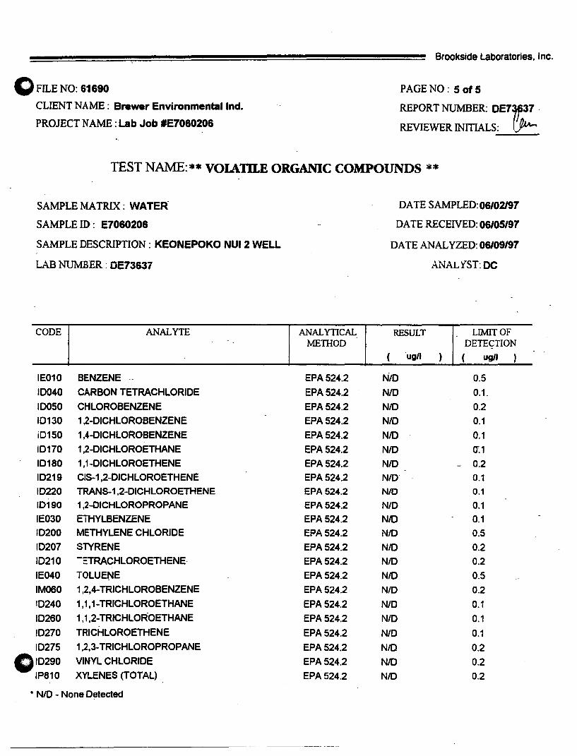
o FILE NO: 61690
CLIENT NAME: Brewer Environmental Ind.
PROJECT NAME: Lab Job #E7060206
Brookside Laboratories, Inc.
PAGE NO : 50f5
REPORT NUMBER: DE7~37 .
REVIEWER INITIALS: (~
TEST NAME: ** VOIAm.E ORGANIC COMPOUNDS **
SAMPLE MATRIX: WATER·
SAMPLE ID: E7060206
SAMPLE DESCRIPTION: KEONEPOKO NUl 2 WELL
LAB NUMBER: DE7363i
CODE ANALYTE
IE010 BENZENE .-
10040 CARBON TETRACHLORIDE
10050 CHLOROBENZENE
10130 1,2-DlCHLOROBENZENE
i0150 1,4-0ICHLOROBENZENE
10170 1,2-DICHLOROETHANE
10180 1,1-0/CHLOROETHENE
10219 CIS-1,2-0/CHLOROETHENE
10220 TRANS-1,2-0ICHLOROETHENE
10190 1,2-DICHLOROPROPANE
IE030 EiHYLBENZENE
10200 METHYLENE CHLORIDE
10207 STYRENE
10210 -ETRACHLOROETHENE-
IE040 TOLUENE
IM060 1,2,4-TRICHLOROBENZENE
10240 1,1,1-TRICHLOROETHANE
10260 1,1,2-TRICHLOR-OETHANE
10270 TRICHLOROETHENE
10275 1,2,3-TRICHLOROPROPANE
010290 VINYL CHLORIDE
IP810 XYLENES (TOTAL)
• NID - None Detected
ANALYTICAL METIIOD
EPA 524.2
EPA 524.2
EPA 524.2
EPA 524.2
EPA 524.2
EPA 524.2
EPA 524.2
EPA 524.2
EPA 524.2
EPA 524.2
EPA 524.2
EPA 524.2
EPA 524.2
EPA 524.2
EPA 524.2
EPA 524.2
EPA 524.2
EPA 524.2
EPA 524.2
EPA 524.2
EPA 524.2
EPA 524.2
DATE SAMPLED: 06102197
DA TERECEIVED: 06105197
DATE ANALYZED: 06/09197
ANALYST: DC
RESULT - LIMIT OF DETECTION -
( ugll ) ( ugll )
NID 0.5
NID 0.1_
NID 0.2
NID 0.1
NID 0.1
NID 0'.1
N/O 0.2
NID· 0.1
NID 0.1
NID 0.1
NID 0.1
NID 0.5
NID 0.2
NID 0.2
NID 0.5
N/O 0.2
N/O 0.1
N/O 0.1
N/O 0.1
N/D 0.2
NID 0.2
N/O 0.2

Laboratory Report
"
Environmental Laboratorv of the Pacific 930 Mapunapuna street. Suite 100
Honolulu. Hawaii 96819 Phone: 808-831-3090 fax: 808-831-3098
~~i!!!iS!~m:I~~i!iI!!!S9!!;S!m~~,~iiIjS!Si!!Bi!ims5:!~~.!!S:S~!!!Si*~iili!Sei!S1!i!S!ISS!i!Si!iS!iliiISSB8Bi!!iSSiii!!S!ISi~!ms!g!l!tllml!e!ssS!Su~!mSiS!S!8!9~X-&i:m rewer .Envlfonmental Lab. Client proJed 10: E7050205 samplea: Jun 2. 1 lib 1m
,311 Pacific st. Sample Description: Water. E7060206-N Received: Jun 2. 1997WJ : Honolulu. HI 96817 Lab Sample 10: 97060006 Reported: Jun 17. 1997f~ : Attention: Lynette Higa Work Ortler #: 9706004 ~~~ ~~~~, ~~~~~iiiS~'liBi!SI!!i8i8i!iliiiSmi;iIS~*,~l!:!!m.iSa!mSiSSi!i!m:$!i'!.m*:~~«;!i!!!sia!S!ii!S&,miS!~iS88iSeS!.ii!m!'!!!:i~,~Si!l!,~,~~,~:*»mm:4:
Analyte Method
e ............. .
LASORA TORY ANALYSIS
Units Reporting Umit
AnaIytes reported as N.D. were not present above the stated reporting limit.
E.L PACIFIC
~/L __
Ken Kawabata Project Manager
Date AnalyZed
Sample Result
Appendx E

o
APPENDIXC
" HYDROLOGIC FEASffiILITY OF ADDITIONAL . WELL SOURCE AT KEONEPOKO RESERVOIR SITE (DWS),
HHL MAKUU FARM LOTS, PAHOA, PUNA, HAWAII, " BY WATER RESOURCE ASSOCIATES.

Hydrologic Feasibility of Additional Well Source at Keonepoko Reservoir Site (DWS), HHL Makuu. Farm Lots, Paboa, Puna, Hawaii
INTRODUCTION
Hawaiian Home Lands needs to develop a source of water supply for its
Makuu F armlot Subdivision located north of Pahoa town. One alternative being
considered is to drill a well at the Keonepoko Reservoir Site, which belongs to the
Hawaii County Department of Water Supply (see Figure 1). The site is located
alongside Highway 130 at an approximate elevation of 60S feet, just south of the
farm lots.
An existing deep well, Keonepoko Nui 1 ,-is located within the reservoir site
and it has an installed pump capacity of 700 gpm. This report discusses the
hydrologic feasibility of developing an additional well source within this reservoir
site to serve the water needs of the Makuu Fannlots Subdivision.
PAHOA AQUIFER SYSTEM
Boundaries. The proposed project is located within the Pahoa Aquifer
System in an area of high rainfall. The aquifer system, which is a part of the 564
square-mile Kilauea Hydrologic Sector, embraces a wedge-shaped area of 222 square
miles extending from Kilauea Crater eastward to the ocean between the Kilauea East
Rift Zone and the Volcano-Keaau Highway (see Figure 2).
Geology. The Pahoa Aquifer System is comprised chiefly of basaltic flank
flows of the Puna volcanic series. These basaltic flows are geologically young (30
to 10,000 years at the surface), relatively unweathered, highly permeable, and
typically yield water readily to wells. The lavas are dike-free, except in the Kilauea
East Rift zone.
Due to their young age and lack of weathering, the permeable basalts readily
absorb rainfall and streams and streamflows are essentially nonexistent
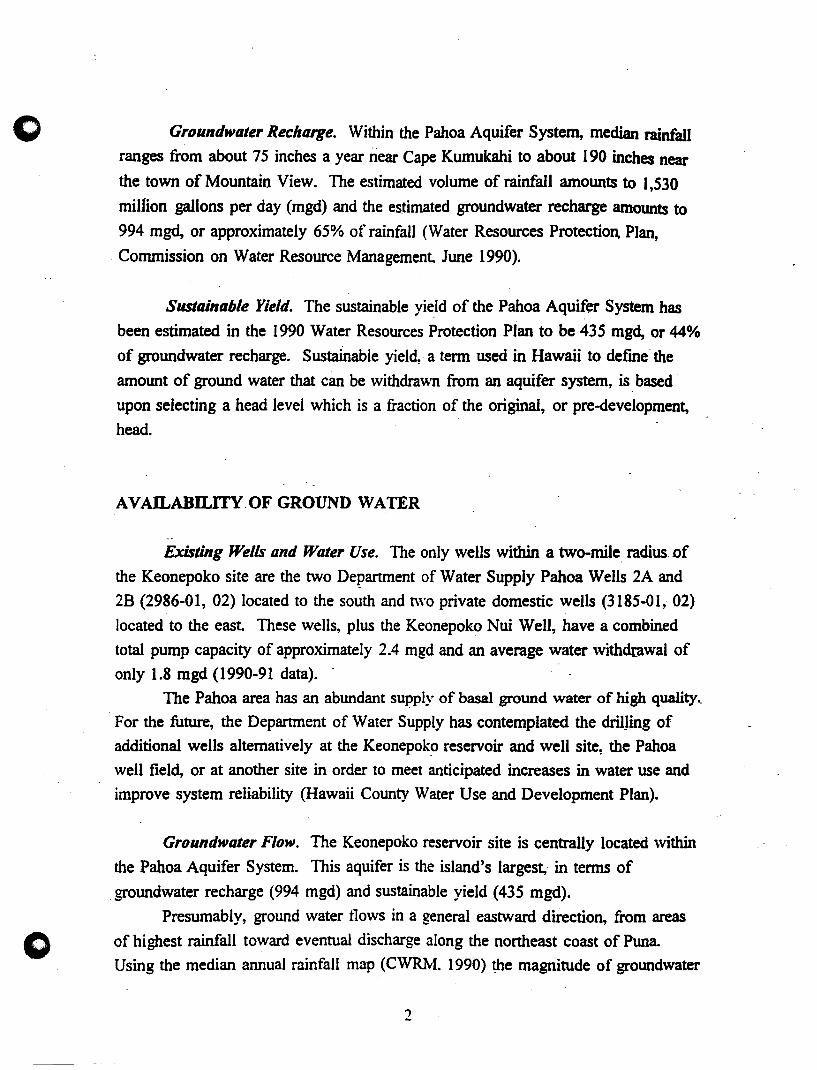
o Groundwater Recharge. Within the Pahoa Aquifer System, median rainfall
ranges from about 75 inches a year near Cape Kumukahi to about 190 inches near
the town of Mountain View. The estimated volume of rainfall amounts to 1,530
million gallons per day (mgd) and the estimated groundwater recharge amounts to
994 mgd, or approximately 65% of rainfall (Water Resources Protection, Plan,
. Commission on Water Resource Management June 1990).
Sustainable Yield. The sustainable yie.ld of the Pahoa Aquifer System has
been estimated in the 1990 Water Resources Protection Plan to be 435 mgd, or 44%
of groundwater recharge. Sustainable yield,· a term used in Hawaii to defme· the
amount of ground water that can be withdrawn fro~ an aquifer system, is. based'
upon selecting a head level which is a fraction of the original, or pre-development,
head
AVAILABILITY.OF GROUND WATER
.'
Existing Wells and Water Use. The only wells within a two-mile. radius. of
the Keonepoko site are the two Department of Water Supply Pahoa Wells 2A and
2B (2986-01, 02) located to the south and two private domestic wells (3185-01, 02)
located to the east These wells, plus the Keonepoko Nui Well, have a combined
total pump capacity of approximately 2.4 mgd and an average water withdrawal of
only 1.8 mgd (1990-91 data). .
The Pahoa area has an abundant supply of basal ground water of high quality ..
For the future, the Department of Water Supply has contemplated the driUing of
additional wells alternatively at the Keonepok~ reservoir and well site, the Pahoa
well field, or at another site in order to meet anticipated increases in water use and
improve system reliability (Hawaii County Water Use and Development Plan).
Groundwater Flow. The Keonepoko reservoir site is centrally located within
the Pahoa Aquifer System. This aquifer is the island's largest, in terms of
groundwater recharge (994 mgd) and sustainable yield (435 mgd).
Presumably, ground water tlows in a general eastward direction, from areas
of highest rainfall toward eventual discharge along the northeast coast of Puna.
Using the median annual rainfall map (CWRM. 1990) the magnitude of groundwater
2

o flowing eastward through the Keonepoko-Pahoa area is of the order of 50 mgd per
mile width. This large amount together with the occurrence of a 600-foot thick basal
lens having a head of 15 to 17 feet, the development of individual well fields with a
pump capacity of at least 5 mgd should be easily attainable without any adverse .
effect on the aquifer's sustainable yield and water quality.
o
Aquifer Cllaracteristics/We/l Spacing. The basal aquifer underlying the
Keonepoko-Pahoa area consists of extensive basaltic lava flows having hydrologic
characteristics which rival those of the water-rich Pearl Harbor aquifer on Oahu.
Fortunately, the Hawaii County Department of Water Supply conducted a reliable
~e-day pumping test (1977) on the Keonepoko Nui Well and the data confirms the
highly penneable nature of the Puna basalts in the Keonepoko-Pahoa area. With an
aquifer penetration of only 65 feet (depth of well = -50 feet, msl), the well has
specific ~ell capacity of 1600 gpm per foot drawdown, exceeding the performance
of wells in the Pearl Harbor aquifer.
The drawdown and recovery of the Keonepoko Nui Well were essentially
instantaneous and during the three days of pumping at 1,000 gpm, the well exhibited
a stable drawdown of only 0.6 feet (see Figure 3). The chloride content of the well
was also stable at 4.0 mgtl. The temperature of pumped water measured 67.5°F
during the night. Elevated temperatures of up to 71°F were measured during the da~time and may have been caused by the use of recirculated pumped water to cool
the diesel engine.
The Pahoa 2A Well, located approximately two miles south, has a specific
well capacity of 628 gpm per foot of drawdO\\TI (about 40% that of the Keonepoko
Nui'Vell). However, the well may not have been fully developed, based on a test
pumping rate of only 314 gpm and a drawdown of 0.5 feet.
CONCLUSION
The Keonepoko-Pahoa area is underlain by a thick, highly penneable basalt
aquifer of high quality (6 mgtl chlorides). Based on a head of 15 to 17 feet, the
basal lens in the area extends 600 feet or more below sea level. Ground water in the
aquifer presumably flows in a general eastward direction from areas of highest
rainfall toward ultimate discharge along the northeastern coast of Puna.

c Groundwater flux in the area is of the order of 50 mgd per mile width wong the
Pahoa-Keaau Highway. Consequently, abundant groundwater resources are available
in the basal aquifer and well fields with pump capacities of 5 mgd or more probably
can be· developed.
Pumping test data confinns the geologically expected high penneability of the
Puna basaltic aquifer beneath the Keonepoko-Pahoa area. The stable drawdown in
the Keonepoko Nui Well of less than a foot at a pumping rate of 1,000 gpm (1.4
mgd) suggests, together with experience, that individual wells within a well field
located in the Keonepoko-Pahoa area can be spaced as close as 100 feet apart
without any adverse interference between wells.
FINDINGSIRECOMMENDATION
All indications are that an exploratory well to provide additional water supply
for the Makuu Fannlot Subdivision can be successfully located within the
Keonepoko Reservoir and Well site .
. The· exploratory well may be located as close as 1 00 fe~t from the existing ..
well, if desired.
It is recommended that the exploratory well be designed to accommodate a
pump capacity of at least 700 gpm.
The exploratory well be pump tested simultaneously with the existing well
and the results evaluated to detennine the capacity of the well field and pennanent
pump for the exploratory well.
4
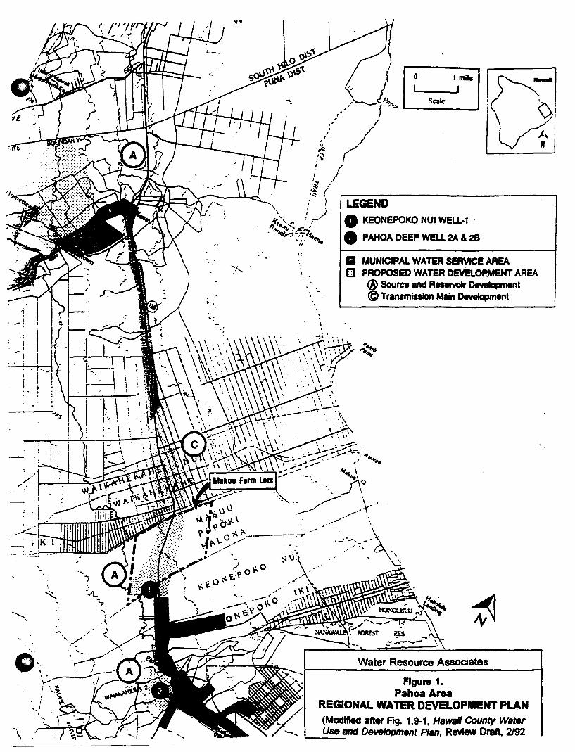
0,;
\
I .,
,!
. ....
---'-07"
, \
'. I
o I mile I I
Sale
LEGEND • KEONEPOKO NUl WELL-1
• PAHOA DEEP WELL 2A & 28
• MUNICIPAL WATER SERVICE AREA CJ PROPOSED WATER DEVELOPMENT AREA
® Source and Reservoir DtMtIopment. @ Transmission Main DewIopment
Figure 1. Pahoa Area
REGIONAL WATER DEVELOPMENT PLAN (MOdified after FIQ. 1.9-1, Hawaii County Water Use and Development Plan, Review Draft. 2192

o Papaikou
()
A N [2:]120001\.
I J SQlc
.~
legend: _40- MecIIII A ...... R .... in incMs • -. Aqui" SystIm 80IIIdIry
• Proposed Wei Site o ~ Will. showing had 1ft.) and c:IIIora ImgJIt
• Raingage
Kalapana
.J Pahoa Aquifer System I
Water Resource Associates
Figure 2. HYDROLOGY AND
PROPOSED WELL SITE Makuu Fannlot Subdlvhllon
Pahoa,HawaU
e
:n 1 w
gpm
PUMPING TEST RECORD Keonepoko Nui Well (3188-01), Pl;Jna, HI
Date of Test: Dec. 6-9,1,977
o
feet
1600 ~------------------------------------'---------------------------------------' 1-
1500
1400
1300
1200
1100 -
1000
800
600
500
400 -
300 - I I
i I ____ --:.i . ____ ~.
200 Pump Test by , \".... Hawaii County DWS
• I 100 -
a a 500
Wat.r R •• ouro. A •• oclat •• 07:J\PulllpT •••
1000 1500 2000 2500 3000 Minutes since pumping began
f------lll- a
- 1
", -2
- - 3
-4
-5
-6
-7
3500 4000 4500 5000

Figure 4. WELL RECORDS
Pahoa-Puna. Hawaii
Yea, Elev. Depth Test Rate Draw· CbIoride Had WII No. WaI Name Drilled 1ft.) Ift.1 1- daMI (ftt - 1ft.)
298&01 Pahoa 2A 1960 705 -50 314 0.5 4 17.8
298&02 Pahoa 28 1965 711 6
3185-01 . Hawn Shores 1964 402 -44 425 1.7 18 10.6
3185-02 Hawn Shores 1971 380 -50 350 3.5 23
3188-01 KeOnepoko Nui 1977 603 -47 1000 0.6 4 15.1
Source of Data: Commission on Water Resource Management.
o
APPENDIXD
WELL PUMPING UNIT SPECIFICATIONS
o

o
SECTION 3.5.1 - WELLPUMPINGUNIT
This section of the specification covers the furnishing and installing of one (1) new vertical motor-driven, water lubricated, open lineshaft deep well turbine pumping unit. The pump shall conform to A WW A E 101-88 specifications.
A. Pump Characteristics:
Number required: One (1)
Pump rated capacity and head:
700 gpm at 640 ft. head (pump efficiency not less than 83%)
Example of pump performance characteristics desired:
1. 0 gpm at 776 ft. head maximum (shutoff head)
2. 400 gpm at 726 ft. head (Pump efficiency not less than 70.0%)
3. 700 gpm at 640 ft. head (Pump efficiency not less than 83.0%)
4. 800 gpm at 583 ft. head (pump efficiency not less than 81.0%)
Pump used to dimension plans and specify pump performance characteristics:
Layne, 1770 rpm (11 BHC - 11 Stages)
B. Motor Characteristics:
Number required: One (1)
Electrical motor rating: 150 HP
Power: 3-phase, 60 hertz, 460 volts
Enclosure: TEFC
Minimum full load motor efficiency: 95.8% (Premium Efficiency)
SP - 65

o
C. DischarKe Head:
Size of discharge flange: 8" - 125#
Class of pipe flange: 125 lb. ASA
D. Dischar~e Column:
Minimum inside diameter: 8 inches
Minimum pipe wall thickness: 0.322 inches (Schedule 40)
E. Line Shaft:
Minimum shaft size: 1.500"
Shaft material: ASTM A276, Grade 410 stainless steel
Coupling material: Type 416 stainless steel.
F. Pumpin~ Unit Efficiency Test Reqyirement:
Minimum guaranteed overall efficiency of pumping unit at rated capacity and head: 76%
G. Well Data:
All elevations refer to Mean Sea Level.
Casing inside di~eter: 16 in.
Elevation of bottom of well casing (perforated steel casing): minus 46.5 ft.
Elevation of base of discharge head: 606.79 ft.
Elevation of bottom of pump bowls: Minus 20.21 ft.
Length of pump column and bowl assembly from base of discharge head to bottom of bowls: 627.0 ft.
Elevation of estimated static water level in well: 16.0 ft.
Estimated drawdown: 5.6 ft. @ 700 gpm pumping rate.
SP - 66

()
o
H. Deep Well Pump .Description:
The pump shall be as manufactured by Layne, or approved equal.
Bowls:
The pump bowls shall be of close-grained cast iron having a minimum tensile strength of 30,000 pounds per square inch, free from blow holes, sand holes and all other faults; accurately machined and fitted to close dimensions. Bowls shall be porcelain enamel lined. Porcelain enameled finish shall be smooth, nominal 8 mils thick, and shall be free of defects such as thin spots, blister, chipping, spray sagging, air bubbles, fish scaling and pinholes. Bowls shall confonn to ASTM A 48 CL 30. The manufacturer shall provide the Engineer with pressure ratings of bowls at shut-off conditions as well as full load.
Impeller Shaft:
The impeller shaft shall be of polished ASTM A 276, Grade 410 stainless steel and shall be supported by suitable noncorrosive bearings on both sides of each impeller and positive means must be provided for water lubricating each bearing. The shaft shall be threaded at the lower end to receive an assembly unit to accurately locate the shaft with respect to the bowls during assembly of the bowl unit. The bottom case bearing shall be bronze or other approved material.
Impellers:
Impellers shall be the fully enclosed type ofbronze cast from new ingot material ofheavy construction, finished allover, accurately fitted and perfectly balanced both statically and dynamically. (Hydraulic "balanced thrust" impellers shall not be permitted) They shall be locked securely to the impeller shaft with a tapered lock bushing or other means. The bowls and impellers shall be designed with open and smooth passages to secure efficient operation and to prevent air locking or sand locking. The impellers shall be so designed as to pennit axial adjustment to compensate for wear. The manufacturer of the pump must provide sufficient clearance in the bowl of the pump he su'pplied to take Care of any stretchini of the shaft under shut-off conditions and any stretchini of the discme column pipe without the impeller makini contact with anY surface of the bowl. The clearance calculations shall be submitted to the Engineer before the pump is installed. Wear rings shall be of ASTM B 505 Alloy 836, bronze construction or other approved material.
Discharge Head:
A suitable pump head ofhigh grade cast iron ASTM A 48, Class 30 shall be provided with the discharge elbow having an aboveground flange discharge outlet. The discharge head shall be designed for the full range of pump operation. The baseplate shall be flat, and a suitable gasket shall be provided between the baseplate and discharge head. The base shall be square with 4 bolt holes. A 314-inch tapped hole shall be provided in the pump base for
SP - 67
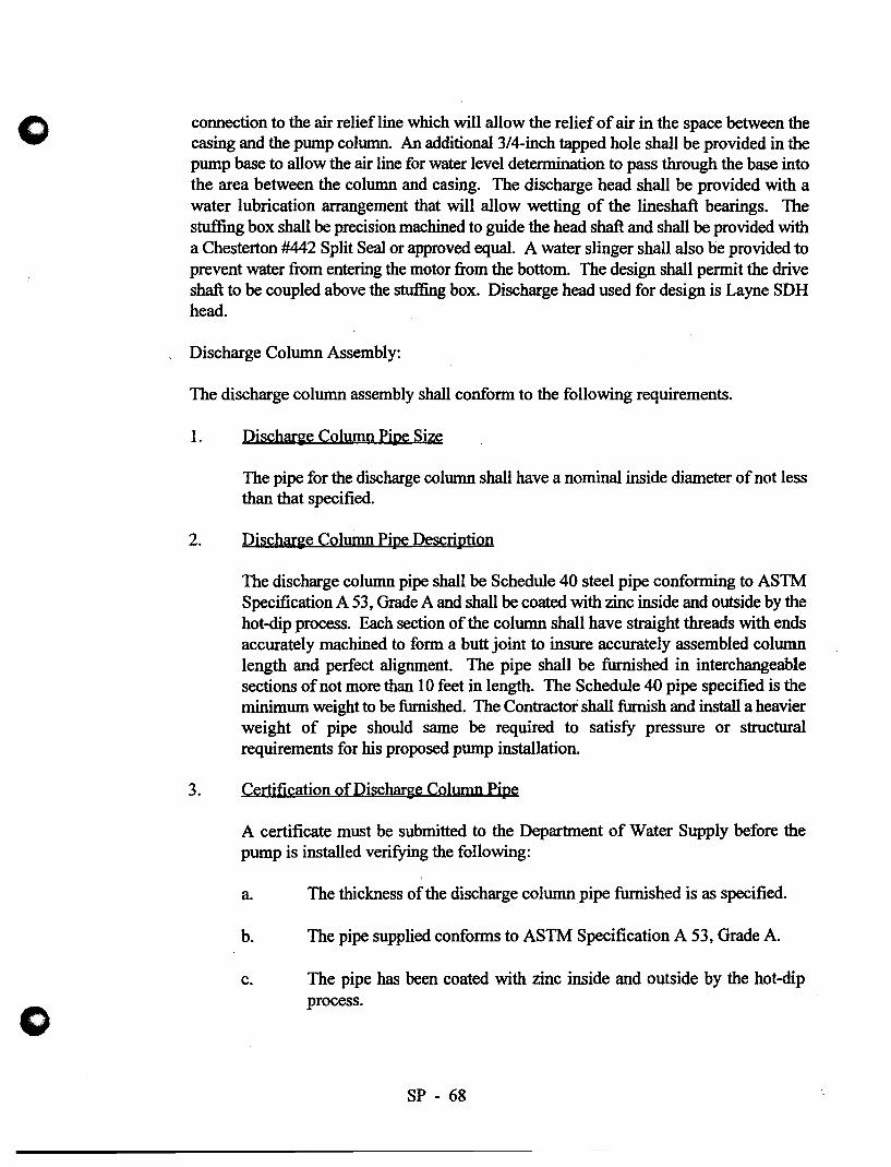
o
connection to the air relief line which will allow the relief of air in the space between the casing and the pump column. An additional 3/4-inch tapped hole shall be provided in the pump base to allow the air line for water level detennination to pass through the base into the area between the column and casing. The discharge head shall be provided with a water lubrication arrangement that will allow wetting of the lineshaft bearings. The stuffing box shall be precision machined to guide the head shaft and shall be provided with a Chesterton #442 Split Seal or approved equal. A water slinger shall also be provided to prevent water from entering the motor from the bottom. The design shall pennit the drive shaft to be coupled above the stuffing box. Discharge head used for design is Layne SDH head.
Discharge Column Assembly:
The discharge column assembly shall confonn to the following requirements.
1. Dischar"e Column Pipe Size
The pipe for the discharge column shall have a nominal inside diameter of not less than that specified.
2. Discharie Column Pipe Description
The discharge column pipe shall be Schedule 40 steel pipe conforming to ASlM Specification A 53, Grade A and shall be coated with zinc inside and outside by the hot-dip process. Each section of the column shall have straight threads with ends accurately machined to fonn a butt joint to insure accurately assembled column length and perfect alignment. The pipe shall be furnished in interchangeable sections of not more than 10 feet in length. The Schedule 40 pipe specified is the minimum weight to be furnished. The Contractor shall furnish and install a heavier weight of pipe should same be required to satisfy pressure or structural requirements for his proposed pump installation.
3. Certification of Discharge Column Pipe
A certificate must be submitted to the Department of Water Supply before the pump is installed verifying the following:
a.
b.
c.
The thickness of the discharge column pipe furnished is as specified.
The pipe supplied confonns to ASTM Specification A 53, Grade A.
The pipe has been coated with zinc inside and outside by the hot-dip process.
SP - 68

o
o
4. Steel Column Coyplin~s
The pipe shall be furnished to interchangeable sections not more than 10 feet in length with lathe cut threads and shall be fastened with threaded sleeve type couplings. The combination column couplings shall be made of ASTM A 48, Class 30 cast iron with aligning spider cast integrally. The butt joint connection shall insure proper alignment.
5. Lineshafi
The lineshaft furnished shall be the minimum size, and the material shall be ASTM A 276, Type 410 stainless steel. Should the manufacturer require a larger sized shaft, he shall provide the required larger size. The lineshaft shall be furnished in interchangeable sections 10 feet in maXimum length. The shaft (10 feet) shall be straight within 0.003" total indicator reading. Lineshaft surface finish shall be 8 to 16 rms.
6. Lineshaft Couplin~
The lineshaft shall be connected with Type 416 stainless steel threaded couplings. The couplings shall be designed with a safety factor of 1-l/2 times the shaft safety factor and shall have a left-hand thread to tighten during the pump operation. An adjusting method shall be provided at the top of the shaft to allow impeller adjustment by means of an adjusting nut to provide a positive l~king device. Each coupling shall have a l/8-inch diameter sight hole to ensure the lineshafts are butt connected.
7. Water Lubricated Graphalloy Bearin~
The pump assembly shall have a full-length water lubricated graphalloy bearing properly spaced in each section of the pipe columns to maintain alignment of the shafting and to prevent vibration. To ensure adequate lubrication and to flush any sand or grit, the graphalloy bearings inside surfaces shall be spirally grooved or provided with grooves of other approved configuration. The graphalloy bearing . shall be lead-free, tin babbitt material Grade OM 205.3 as manufactured by Graphite Metallizing Corporation, 1050 Mepperhan A ve., Yonkers, New York 10702 (do not substitute). The pump contractor and/or supplier shall submit to the Engineer for approval the minimum water lubrication rate necessary to ensure adequate lubrication to the bearings supplied for the entire assembly.
SP - 69

o
o
8. Suction Case
The suction case shall be the venturi type with streamline vanes conducting water from the inlet to the eye of the first stage impeller. The suction nozzle bearing shall be bronze, grease packed, extra long sleeve type with a sand collar for protection against sand and grit.
Strainer:
The strainer shall be of the tapered cylindrical type and shall be attached to the bottom of the suction pipe by means of a threaded connection. The net area of the screen openings shall be not less than twice the area of the pump suction opening. The strainer shall be stainless steel.
Base Plate:
A cast iron base plate shall be furnished for mounting the pump discharge head and shall be properly fitted in as part of the concrete pump foundations to seal off water and other contaminants from entering the well. The base plate shall be surface machined and drilled, and tapped to fit the pump discharge head. The opening of the base plate shall be large enough to allow the installation of the pump bowl assembly, pump discharge column, air breather pipeline, and well water level recorder air line.
I. Motor Description:
The motor shall be a normal torque, normal starting current, weatherproof, vertical hollow shaft, squirrel cage induction motor with NEMA Totally Enclosed Fan Cooled (TEFC) enclosure and shall conform to the Standards of the National Electrical Manufacturers Association. The motor shall be rated for 480 VAC, 3 PH, 60 HZ, 1,800 RPM, 1.15 Service Factor, premium efficiency. Minimum full load efficiency shall be 95.8 percent.
The motor shall have a horsepower rating of not less than specified and shall be General Electric Tri-Class Vertical Hollow-Shaft Induction Motor; Westinghouse Vertical HollowShaft; or approved equal. The motor shall have adequate capacity to drive the pump continuously under the head specified with a temperature rise of not more than 40 degrees C.
The motor shall be equipped with space heaters rated 120 VAC, 1 PH, with wattage as required by the motor manufacturer. Space heater loads shall be brought into the motor terminal box or it shall have a separate terminal box of its own for conduit connection.
SP - 70

o
o
The motor shall have an efficiency of not less than that specified when operating under full-load conditions. The bearings in the motor shall be oil lubricated. The motor thrust bearings shall have ample capacity to carry the thrust loads of the pump thrust and weights of the pump shaft and pump rotating element with the pump operating at shut-off head conditions. The thrust bearing shall be of such size that the average life rating is based on 5 years of continuous operation.
The motor shall be designed to prevent reverse rotation when the unit is shut down.
The selection of the motor shall be the responsibility of the Contractor and Pump Manufacturer and must meet the approval of the Engineer before it is ordered.
Manufacturer's certified copies of test run on a motor of the same type, size and model as the one being furnished shall be forwarded to the pump supplier for inclusion in the bound sets for submittal to the Engineer. Test data shall include:
1. A.C. winding resistance
2. No load current
3. Full load current
4. Locked rotor current
5. Starting torque
6. Motor efficiency at 50, 75, and 100% full load
7. Power factor at 50, 75, and 100% full load
8. Power factor at full load with 90 and 110% rated voltage
J. Spare Parts:
Each bidder shall supply and deliver the following list of spare parts to the Department of Water Supply Hilo Baseyard.
One (1) extra set of bearings for the pump motor.
One (1) extra set mechanical seal for the pump.
SP - 71

APPENDIXE
FUTURE WELL SITE LOCATION

BENJAMIN J. CAYETANO GOVERNOR Of HAWA"
MICHAEL D. WILSON CHAlIl'ERSON
TO:
FROM:
STATE OF HAWAII DEPARTMENT OF LAND AND NATURAL RESOURCES
COMMISSION ON WATER RESOURCE MANAGEMENT P. o. BOX 821
HONOLULU. HAWAII 96809
June 8, 1998
Mr. Thomas Arizumi, P.E., Chief Environmental Management Division Department of Health
Timothy E. Johns, Deputy Directo~~' ~ Commission on Water Resource Management
ROBERT G. GIRALO DAVID A. NOBRIGA LAWRENCE H. MilKE
RICHARD H. COX HERBERT M. RICHARDS. JR.
TIMOTHY E. JOHNS OEPUTY OIAECTOR
SUBJECT: Keonepoko Nui 2 Well Engineering Report
EMD/SDWB FILE NO.:
Thank you for the opportunity to review the subject document. Our comments related to water resources are marked below.
In general, the CWRM strongly promotes the efficient use of our water resources through conservation measures and use of alternative non-potable water resources whenever available, feasible, and there are no harmful effects to the ecosystem. Also, the CWRM encourages the protection of water recharge areas which are important for the maintenance of streams and the replenishment of aquifers.
[ x ] We recommend coordination with the county government to incorporate this project into the county's Water Use and Development Plan.
[] We are concerned about the potential for ground or surface water degradation/cont:uain:rlloii and recommend that approvals for this project be conditioned upon a review by the State Department of Health and the developer's acceptance of any resulting requirements related to water quality.
A Well Construction Pennit and/or a Pump Installation Permit from the CWRM would be required before ground water is developed as a source of supply for the project.
The proposed water supply source for the project is located in a designated water management area, and a Water Use Pennit from the CWRM would be required prior to use of this source.
Groundwater withdrawals from this project may affect streamt1ows. This may require an instream flow standard amendment.
If the proposed project diverts additional water from streams or if new or modified stream diversions are planned, the project may need to obtain a stream diversion works permit and petition to amend the interim instream flow standard for the affected stream(s).
[] If the proposed project performs any work within the bed and banks of a stream cbannel, the project may need to obtain a stream cbannel alteration permit and a petition to amend the interim instream flow standard for the affected stream(s).
We recommend that no development take place affecting highly erodible slopes which drain into streams within or adjacent to the project.
OTHER:
If there are any questions, please contact Mr. Ryan lmata at 587-0255.

~. -'[ COMMISSION ON WATER RESOURCE MANAGEMENT (4/98)
FROM:_.....:E=d'--______ DATE:_...;;.G:~/'-Il_fI-1..L...:6::;..· __ SUSPENSE DATE _______ _ / 1
INIT. PLEASE:
}
_I BAUER, G. ~ _ LUM, A.
~HING' F. _ NAKAMA, L.
FUJII, N. _ NAKANO, D. HARDY, R. ~ ..:!::- OHYE, M.
_ HIGA, D. '\ SAKODA, E. HIRANO, E. 5(1 SUBIA, S. ICE, C. _ SWANSON,
..::::z... IMATA, R. ~ _ UWAINE, J.
~AI' R. _ UYENO, D. _ IMURA, I. _ YODA, K.
JO~iT. ~~ tvl Wu
__ Approval See Me __ Signature ~ Review & Comment
+--=- __ Information Take Action ~~'-I*' ~~ ..-3.. Type Draft
-2.. Type Final
Ik /..{;ti-). ~ ~~~v~· 'ur:~~.~ ~nl.A~k.~
V ;fk- ~ -6/! ~ .. 1 7 ~ 1.4 (q .~" v-p. ~Tt.;t:r- A ~ • rP
OfL
--BENJAMIN J. CAYETANO
GOVERNOR OF HAWAII
STATE OF HAWAII ~n~1AY I An: 57
LAWRENCE MilKE DIRECTOR OF HEALTH
DEPARTMENT OF HEALTH In reply, please refer 10: P.O. BOX 3378 EMO I SOWS
HONOLULU, HAWAII 96801
April 23, 1998
The Honorable Michael D. Wilson Chairman of the Board Attn: Mr. Edwin Sakoda, Acting Deputy Director Department of Land and Natural Resources 1151 Punchbowl Street Honolulu, Hawaii 96813
Dear Mr. Wilson:
SUBJECT: PROPOSED SOURCE OF POTABLE WATER
Enclosed for your review and comments is a copy of the engineering report for the following source:
Keonepoko - Nui 2 Well State Well No. 8-3188-02 Pahoa, Puna, Hawaii
This report has been prepared pursuant to Hawaii Administrative Rules, Title 11, Chapter 20, Rules Relating to Potable Water Systems, section 11-20-29.
The Department of Health will use your comments in determining the potential impacts which may result by the proposed project.
Please submit your comments to the Safe Drinking Water Branch within 30 days from the date of this letter. You may also return the engineering report to this office if you do not need it for future reference.
If you should have any questions, please call the Safe Drinking Water Branch, Engineering Section, at 586-4258.
s(~cerelY,
'/:Jid;f!/k /~THOMAS E. ARIZUMI, P.E., Chief ~Environmental Management Division
QK:la
Enclosure

CWRM DLNR 1151 Punchbowl Street
Honolulu, Hawaii 96813
Pumping test analysis Time-Drawdown-method after COOPER & JACOB Confined aquifer
Project: Keonepoko Nui #2
Evaluated by: Glenn Bauer
Pumping Test No. 1 Test conducted on: May 29-June 3, 1997
Well 3188-02
Discharge 1000.00 U.S.gal/min
t[d] 10-2 10-1
0.00 I I I I I I I I I I I I I I I I I I I I I I I I
I I I I I I I I I I I I I I I I I I I I I I I I
0.70 I I I I I I I I I I I I I I I I I I I I I I I I I I I I I I I I I I I I I I I I I I I I I I I I
1.40 I I I I I I I I I I I I I I I I I I I I I I I I I I I I I I I I I I I I I I I I I I I I I I I I
2.10 I I I I I I I I I I I I I I I I I I I I I I I I I I I I I I I I I I I I I I I I I I I I I I I I
2.80 , I I I I I I I , I I I , I I , I I I I I I I I
g 3.50 II)
I I I I I I I I I I I I I I I I I I I I I I I I
I I I I I I I I I I I I I I I I I I I I I I I I I I I I I I I I I I I I I I I I I I I I I I I I
4.20 ~~lllol o I I I I I I I I I I I I I I I I I I III"Tfr ~ 10 10 I 10 II I I I I I I I I I
4.90 I I I I I I I I I ~ I I I I I I I I I I I I I I I I I I I I I I jO I ~I I I I I I
5.60 I I I I I I I I I I I I I I I I I I Pol l'"""t-+-I.... I I I I I I I I I I I I I I I I I I I I I I I I
6.30 I I I I I I I I I I I I I I I I I I I I I I I I
I I I I I I I I I I I I I I I I I I I I I I I I
7.00 03188-02
Transmissivity [ft2/d]: 6.68 x 10⁴ /
Storativity: 1.69 x 10⁻⁵

I
• CWRM Pumping test analysis Date: 05.08.199~ Test, Page 2 DLNR Time-Drawdown-method after
Project: Keonepoko Nui #2 1151 Punchbowl Street COOPER & JACOB Honolulu, Hawaii 96813 Confined aquifer Evaluated by: Glenn Bauer
~
Pumping Test No.1 Test conducted on: May 29-June 3, 1997
Well 3188-02 3188-02
Discharge 1000.00 U.S.gal/min Distance from the pumping well 1.00 ft
Static water level: 586.70 ft below datum
Pumping test duration Water level Drawdown
[d] [ft] [ft]
2 0.01042 591.19 4.49 3 0.01389 591.20 4.50 4 0.02083 591.22 4.52 5 0.U2f7tS 591.24 4.54 6 0.04167 591.25 4.55 7 0.08333 591.26 4.56 8 0.120UU 591.30 4.ou 9 0.2U833 591.37 4.07
10 0.33333 591.42 4.72 11 0.41667 591.47 4.77 12 0.0200U 591.5U ·4.8U 13 0.60667 591.94 5.24 14 0.83333 592.07 5.37 15 1.45833 592.14 5.44 16 2.000UO 591.93 :>.23 17 3.33333 592.18 5.48 18 3.62500 592.30 5.60 19 4.U8;:S;:S;:S 592.39 5.69 20 4.58333 592.49 :>.79

o
o
ENGINEERING REPORT
KEONEPOKO - NUl "2 PRODUCTION WELL
AND SUPPORTING FACILITIES
PAHOA, PUNA, HAWAII
Prepared for:
Department of Hawaiian Home Lands State of Hawaii
Prepared by:
Engineers Surveyors Hawaii, Inc. 1020 Auahi Street
Suite No.1," Building No.6 Honolulu, Hawaii 96814
April, 1998

o TABLE OF CONTENTS
I. GENERAL INFORMATION
A. Purpose of Report B. Description of Water System C. Name of Owners and Authorized Representatives
ll. PHYSICAL AND HYDROLOGICAL CHARACTERISTICS OF THE PROJECT SITE
A. Location B. Physical Dimensions of the 'Well C. Climate D. Topography and Site Description E. Geology and Foundation Conditions F. Earthquake Considerations and Design Parameters G. Groundwater Conditions H. Flood Conditions I. Conformance with Land Use: and Zoning Regulations J. Water Development and Future Use
Ill. EXTENT OF WATERWORKS SYSTEM
A. Description of Existing Systc::ms and Future Service B. Description of System Population and Consumption C. Appraisal of Future Requirements of System D. Provisions for System Extension/Expansion E. Fire Protection and Pressure Capacities F. Alternate Solutions/Supporting Data for System G. Archaeology and Historic Sites H. Environmental and Economic Impact
IV. POTENTIAL SOURCES OF CONTAMINATION
A. Description of Well Site B. Orientation Maps C. Water Quality and Contamination Analysis D. Hazardous Materials E. Land Use Classification
V. SOURCES OF WATER SUPPLY
i
0
o
VI. PROPOSED TREATMENT WORKS
VII. PUMPING FACILITIES
VIII. FINISHED WATER STORAGE
IX. WATER DISTRIBUTION SYSTEM
X. FINANCING
XI. PROFESSIONAL ENGINEER CERTIFICATION
XII. REFERENCES
EXHIBITS
A. Vicinity Map
B. Location Map
C. Keaau-Pahoa Extension (12" Trunkline)
D. Tax Map Key for Keonepoko-Nui Well and Reservoir Site
E. Projected Water Demand
F. Plan Showing Existing Drywells and Individual Wastewater Systems in Relation to Water Wells
APPENDIX
A. WELL COMPLETION REPORT - KEONEPOKO NUl 2 WELL (3188-02)
B. RESULTS OF DRILLING AND TESTING
c. "HYDROLOGIC FEASffiILITY OF ADDITIONAL WELL SOURCE AT KEONEPOKO RESERVOIR SITE (DWS), HHL MAKUU FARM LOTS, PAHOA, PUNA, HAWAII," BY WATER RESOURCE ASSOCIATES
11

o D. WELL PUMPING UNIT SPECIFICATIONS
E. FUTURE WELL SITE LOCATION
F. CONSTRUCTION PLANS, SHEETS C-l,C-3, C-4, C-7 AND M-l
iii

o I.
o
GENERAL INFORMATION
A. PURPOSE OF REPORT
The Department of Hawaiian Home Lands (DHHL) needs to provide a potable water source for the Makuu Farm and Agricultural Lots Subdivision. The development and use of this production well and supporting facilities have been approved by the County of Hawaii Department of Water Supply (DWS), subject to approval of this report by the State of Hawaii Department of Health (DOH). This engineering report has been prepared to satisfy DWS and in accordance with Administrative Rules, Title 11, Chapter 20, "Rules Relating to Potable Water Systems", Section 11-20-29.
B. DESCRIPTION OF WATER SYSTEM
The proposed project would construct a production well and supporting facilities at the existing Hawaii County Department of Water Supply (DWS) Keonepoko Nui well and reservoir site. The project has two purposes:
o The most important objective is to develop a source of potable water supply for the Department of Hawaiian Home Lands (DHHL) Makuu Farm and Agricultural Lots.
o Secondly, locating the well at Keonepoko Nui, adjacent to an existing well, will also provide a needed back-up well for the DWS Keonepoko Nui site.
The Makuu Farm and Agricultural Lots Subdivision will ultimately have 375 agricultural lots created in two phases of development.
Phase I has already been constructed. It consists of 177 lots of which 127 are five-acre lots and the remainder of 50 are two-acre lots. For Phase II, 198 two-acre lots are planned and this phase is in the holding stage.
The Keonepoko-Nui 2 Exploratory Well (Well No. 3188-02) has been successfully completed (See Appendix "A"). It is on the same site as the existing DWS deepwell Keonepoko-Nui 1 well (Well No. 3188-01) and existing 0.5 mg concrete reservoir tank. The site is located just south of the DHHL subdivision (See Exhibit "A", Vicinity Map and Exhibit "B" , Location Map).
The existing Keonepoko-Nui 1 well has an installed pump capacity of 700 gpm. The second well is 120 feet from the existing production well. The second well will also have an installed pump capacity of 700 gpm.
- 1 -
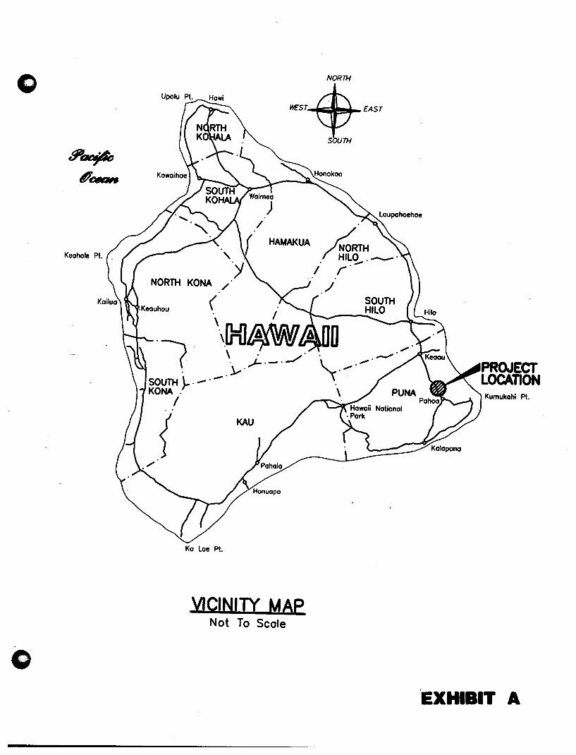
o
Keohole Pt. _
o
NORTH
~T-$-£AST
". -SOUTH}-" -" KONA "
I
Ko Loe Pt.
HAMAKUA
VICINITY MAP Not To Scale
SOUTH
~RTH /~~~"-" i ,"
" "
,I SOUTH HILO
'EXHIBIT A

o
LOCATION MAP Not To Scale
c
SITE LOCATION
EXHIBIT B

o This facility is in the Pahoa Water System (PWS) I.D. No. 111. The existing Keonepoko-Nui Well and Storage Reservoir will not be able to serve part of Phase I and all of Phase II developments due to topography and location of the existing reservoir. Because of this inadequacy, water services for Phases I and II are divided into two service levels (high and low). Of the total 177 lots in Phase I Development, 99 five-acre lots, which are located at lower elevations, will be served by the Department of Water Supply's existing Keonepoko-Nui Reservoir (low service). The remaining 78 upper elevation lots, consisting of 28 five-acre and 50 two-acre lots, would be without water service until a new source and reservoir (high service) are installed in the future. All 198 lots in Phase IT are to be served by the high service system in the future.
The current phase is the planning and design for converting the exploratory well into a production well with supporting production facilities including a permanent 700 gpm pump, piping, chlorinator/control building and equipment.
This source facility will be designed and developed such that potable water from this second production well will be pumped into the existing 0.5 mg Keonepoko-Nui reservoir by a submersible pump whenever operation requires.
Presently there is no waterline connecting the Keonepoko-Nui well and reservoir to the Makuu Farm and Agricultural Lots. DWS plans to install a 12-inch waterline to connect the Keaau and Pahoa water systems. This would include a waterline connection to the subdivision (See Exhibit "e"). This is discussed in Section IX, Water Distribution System.
C. NAME OF OWNERS AND AUTHORIZED REPRESENTATNES
The reservoir and well site is owned by the State of Hawaii. DWS is working with the State Department of Land and Natural Resources (DLNR) to get a formal conveyance through an executive order from the Governor, State of Hawaii. The existing 0.5 mg reservoir, production well and supporting facilities are owned by DWS. The proposed second production well and supporting facilities will be licensed by DHHL to DWS for operation and maintenance.
The following is a list of authorized representatives:
- 2-
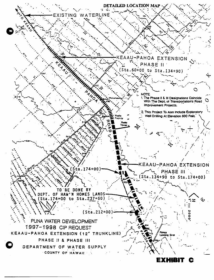
...... '.':. ~.' .... ~. DETAILED LOCATIO~ MAP ./ .. /',", ,;'-..: ~.:. ~!;"
\
_ > '.' ">. . .' .,/ .. '._ OJ A".. -:., / ' .. _.' , • - /._ . ~ ... ~ • _,,-. v" / ... ...... •. / ." . . ". .~. ~~ )00 ~ ... ~ 4..... ~. +. ..; ,_ i-~'" / . /'
J ' • J N E iJ'l / . • •. • ~ ~ I ..... • • •• l· ~, :;..'\i.... . . :.' EXISTING W A TERL "'0./ .-. 0·· ..... · . .; 1 ... ,"+ • .(1.' .: ••••. -/>~ ... / o • '.';. ;". .~. ""\ . • ... ~ ".~~ ." I •. "i'. ." . • .~. ~"' .•• /_ 7 \-",' 1-t\.~.. .~. ,- ' •• /., .. .;',. - +., ............ .. ".. ; •• ",.. " •• -,m
• {<\~4W" •. ~"?,.~,>,, ..... ~ I .... '..... .• / <-.:- '_. .~) -,_.- '., _.. • ':~ , ~")t~. ~ ~ .~ '. "'!',o ' ...... ~.:. .. ..... ,",. ......, "-1 ~/ Ji V
0.' ,~.!.~ •• ~,,-~ • c...~:/'-: ..... / ... ~. "\... . .... ,( ~:" .. ~ ..;;".~r / Sy. ... ·' . J~ ••
" • .• '- ~ • • • ",-. Joo· ,.. • • / • \\;_ lIP, .. :.~ .~, , / ,""~.. • ~": ").- "~.. .~ .... '.. r.~. y'. ('
• ~~. c,-,..,.J '. • ~. /. . • . ... / . '-' c • ':>:~~. .:.~ '- ..... ..... '. ~J. .' ::. .;. • .. L..., .....' .• , ,.. ~ .. ·,v.. .. • ... ,...... . .. ' ... "'):"' \ ~. I ..{.' . / -:. .- . ..., ... . ". ../' . "
• ~' .... "'; ~+~ ~. . .... : ... ..c.: "",,- ,,/ ' . ..: ~ v • ...... "... +. ~ ',. '" : .... v .. -. -.. ~~.. _) I .'
~ / r;~ " ... '~ ~';,. ........ .,.. • \ .' -. '" I. .. . ". l· - '~ <." , / ~ .', +" .... ~ •• X "'''. '.".~':.,,,~ ............ /.::./ ,)
. .
':'::: 0" ' ~~~. +:' .. ~~f.l., ~. KE'A~'~-~~H~~ E'~;ENS'~'N' .
"X "X~, '.-.~~'. .. .... ~ .. ~.: PHASE- ,', : ~/!'\"
' ..
,. ./ /
... ...;;," ...... . '" ¥ .;~'?: . :''>\i\ >. (Sta. 60+00 t~ 'Sta .134+90)
,:t£,~ .. / ........ "", -..., , ~ .. . .-, _. ... 'r .~.:' -'-' ., ~ .... /. ........._ .... _
c,'". ..~ . .....' f :). ..... -...... - ~:~ '/ - .... J-' + .-." -. .. '~." ........ .4.1... ~ ~- .• '~- .... '.-.. -!
.... io +. ..~.. p .:,. ..", ... /- y/ ... "'\.... -". ~~_. /"" .. __ ..... .....-_., !t ... ,.. • • ", ~ ... ' I. ... 7,-__ ~,,,"..,,
'" "'~ £JJ ... ,\ ~.. .... / "? ,... .. ... l "I ...
..... . .;( ..... ~~ .. ~.~ ••• 7.\. ~~.:~/ ~ 0 • a \ ~. +." .... ..... • '£;)
v.. / •. ....... .. '-:::: .~. I, NOTE: " .. ; • . .... I ... ~ w"~'''''':II,(. -1.( 1. The Phase II & III Designations Coincide t""-
./~·.r.. .. 1 ~". 12 "~ ••. > .".'l"; ~th .'!he Dept ot Trans~':lation's ~oad . \..J
,. '... .... ~ "T. .. 7 ?._...... Improvement Projects. "
.... ;;( /. :; 2 This Project To Also Include Exploratory \-
• " .. ~.~~.dIO'- '~; Well Drilling At Sevation 600 Feet' \
_":!- :: .~~: • ." \-""~=-: C". . __ , _) /
J~.... .:: : '",:~t:~ T~ ~ ',_ ", .-~ + ~./. · .. . •.. '. y'/~"" t.. • • ". ; .. :; ...... •.•• •••• OJ ) ~ IF ',.('J'-. : i . " I ".-
1 •• ~ ... "- "., "".. • ~ ) ... ~; • ',I . . $£1 .. '.7..~ ..... /..,. .', ( ", "'. , .. / .
... I • • ..... ~ .. I ":.. ~;.. _/' .' \ ... , , " :
'4°·· .. ·• .';'.'/'" l' '., '-v--........ '-'O~ ." t" t ":;:.:-..1 ...... ,'. .. . J .. ';.' •• ~ ...... .,:.~ ./., ~\_ • ~ '.' '. :' /' .. ~ ~~ •. y. ... ~_ .. ! . . \. ;
.... • 1~ .: .. /. ~ .~ -'" S.J • ... .,,~;4 ...... -I ."~. , , • • .. . ~.... ....... r i" / • • .~ •• ?~ ~:. ft..!. / _~ I.'
."/3:\ ~'" .. ,~ .. :' .. ~':-.. '~"-'-- "-'1 / ".
~\' '\'\'" o"~.;:~~;.~.~ .. ~ ... ~~ . . ·~·~.:~~I !.' : (' KEAAU-PAHOA' EXTENSION ... \0 JI/:--... +,.~ '" /~~ ~~St 174+00) . '" '\ . \ ":-".~'?: ~ •• !f .. ~~~ .... ~ ... I'.. .a. -...........:.1 ~ .-/\..... . PH'ASE' III . r·.
t.. \ ..... At"" .... .... •• ,. . ...... ' .'. • .• • ~ I, L'-/ \... '. -. ~~.~. ~ .. ~ .... X. ": ... >~:."~,,~, "'0,\'" ". ':.~ "_'" (Sta.134+90 to Sta.174+00)
.. '~'IO~~ .~/ ........ wq.,.·. .. . I " ' ...... Ii ,_ •. "" ',' ~ ,l . ~t"'\' ;~ .. "'.... ... +,,' .~ ..... ··r./· ' . ". ,,- 52S~ :, . . \', . '\ .. ) rY
.. • .",~ .. ..... •• •• .. /' , • , • I...... , I \, I .'
:... \ '\ ••... \:\~ . ~ • ·TO"· BE DONE BY' :". ~l.._.' j:.. ~ / \".,., \ \ .\. \ DEPT. OF HAW' N HOMES LANDS \., '-" t). ::, ....... ", \~
.)\:~~:~~~~ft~? to.~ta._~;37+\O~: .. :" ~ ;-?,-.. ;~;z ~ ... '\ \. \ \ \ ~;~~ . (Sta.212+00)---~ '1 ... ~, L ~
) '. .~ t .... , , 0
:"~ •. \.'~ PUNA WATER DEVELOPMENT' ,._'\.. ... ' l., )'\.) l " ~ 1997-1998 CIP REQUEST ' J ~ ~ a" ';·-1"'--''-
KEAAU-PAHOA EXTENSION (12' TRUNK LINE) YC ~-s. ·/~=9~lttO .. PHASE" & PHASE III ._,-' / __ ._~ ~,.".<~~, c.;, o 0 EPARTMENT OF WATER S UPPL Y .,-1;' . ( .. \ : ,"1.--·1.'
'. " ,. " \
/
/ /
~
'.1
I..
/ · COUNTY OF HAWAII
EXHIBIT C

o
c
1. LANDOWNER:
State of Hawaii Department of Land and Natural Resources Land Management Division 1151 Punchbowl Street Honolulu, Hawaii 96809
Authorized Representative: Michael Wilson, Director Contact Person: Dean Uchida, Ph. (808) 587-0414
2. EXISTING PRODUCTION WELL (WELL NO. 3188-01) AND SUPPORTING FACILITIES:
County of Hawaii Department of Water Supply 25 Aupuni Street Hilo, Hawaii 96720
Authorized Representative: Contact Person:
Milton Pavao, Manager Owen Nishioka, Ph. (808) 961-8660
3. EXISTING EXPLORATORY WELL (WELL NO. 3188-02); (Note that the future· production well and supporting facilities will continue to be owned by DHHL, but will be licensed to DWS for operation and maintenance):
State of Hawaii Department of Hawaiian Home Lands 335 Merchant Street, Room 345 Honolulu, Hawaii 96813
Authorized Representative:
Contact Person:
Kali Watson, Chair Hawaiian Homes Commission Pat Young, Ph. (808) 586-3817
II. PHYSICAL AND HYDROLOGICAL CHARACTERISTICS OF THE PROJECT SITE
A. LOCATION
The site is located alongside Highway 130 at an approximate elevation of 605 feet, just south of the Makuu Farm and Agricultural Lots, TMK: 1-5-08: portion of 1 (See Exhibit "D", Tax Map Key for Keonepoko-Nui Well and Reservoir Site). It's location is approximately 2000 feet from the Pahoa Landing Airstrip on the highway. (See Exhibit "B" , Location Map).
- 3 -
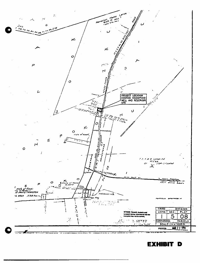
·""~'
p
o
o -- --_ ..
", ::.:. ",
.. -.~-
o
'-,,' ~ ".
o
i II t-'). -I
~
\" ,
........ ..... ~. ", ~ '~' . o -/ " ' .0 / .... /
~. / ~. I
., I ,~ !
1;" V , "
PROJECT LO
/ /
/
EXISTING KEg·UION ,'U
WELL AND NEPOKO • /
..... JJ.~:::::. ___ S;;;.:I.:.:TE=--__ RESERVOIR .... » .,/. : ~/"
:::__ _" •• ~.4 ••
SA:::: -~~--..
--."eeL. t ..... ••••. ~. ... ....
wmce:o....... ::" .. _-=,--_ ....... .....: ...... '!; SI11.·,'1' .. l!
, .. ~.: I .. : ~.: /. ' . . • ; ... t,,;, .1."
----_ .. _ .. -
EXHIBIT D

o B.
The existing exploratory well is located 120 feet from the existing Keonepoko-Nui 1 well production (See Appendix "Go., Sheet C-3).
PHYSICAL DIMENSIONS OF THE WELL
The Keonepoko-Nui 2 Well is a 23-inch diameter, 650-foot deepwell (Appendix" A", Well Completion Report - Keonepoko-Nui 2 Well). The ftrst 550 linear feet is cement grouted. The 16-inch solid casing is 590 feet from the top of the well casing. The perforated casing is 60 feet. the bottom of the well is at -46.53 feet MSL. In addition to the Well Completion Report, a supplemental report was prepared, Appendix "B", Results of Drilling and Testing.
C. CLIMATE
Within the Pahoa Aquifer System, median annual rainfall ranges from about 75 inches at Cape Kumukahi to 190 inches near Mountain View. This high rainfall produces about 994 million gallons per day (mgd) in groundwater recharge (Water Resources Protection Plan, Commission on Water Resource Management, June 1990).
D. TOPOGRAPHY AND SITE DESCRIPTION
The ground underlying the site is classifted as Lava Flows, Pahoehoe (rL W) according to the "Soil Survey of Island of Hawaii, State of Hawaii" produced in 1973 by the U.S. Department of Agriculture, Soil Conservation Service. Lava flows, Pahoehoe (rLW), has been mapped as a miscellaneous land type. This lava has a billowy, glassy surface that is relatively smooth. In some areas, however, the surface is rough and broken, and there are hummocks and pressure domes.
The site of the proposed improvements is an approximately 1 acre pad adjacent to the existing well/reservoir site. It has already been graded as part of the exploratory well project. The graded terrain was covered with cinders and is now flat. Vegetation on the pad consists mainly of weedy grasses, herbs and trees, especially sensitive plant (Mimosa pudica), sourbush (pluchea odorata), rattlebox (Crotalaria pallida), molasses grass (Melinis miuutiflora), guinea grass (Panicum maximum) gunpowder tree (Trema orientalis) and melochia (Melochia umbellata). The native 'uhaloa (Waltheria indica), which thrives in disturbed conditions, is also present.
Surrounding the pad is an area of native scrub forest composed principally of ' ohi' a (Metrosideros polymoq>ha.) and uluhe fern (j)icranopteris linearis). A low forest (10-30 feet) of scattered 'ohi' a trees (10% upper canopy cover) surrounded by uluhe is typical, interrupted by more disturbed vegetation emanating from the roadside verge. Additional prominent floristic elements include native and alien sword ferns (Nephrolepis spp.), the native species 'uki'uki (Dianella sandwicensis), and the aliens melastoma (Melastoma candidum - which covers approximately 50 % of the shrub canopy), guava (Psidium ~ajava), wai' awi (Psidium cattleianum), bamboo orchid (Arundina ~raminifolia), and broomsedge (AndrQpo~on yirginicus).
-4-

o
Disturbed areas such as the pad do not provide habitat for native animals. Alien bird species such as Japanese white-eye (Zostemps japonica) and cardinal (Cardinal is cardinalis) are common on the site and surrounding area. Mammals such as Indian mongoose (JIerpestes aUrQpunctatus), feral cats (Felis catus), rats (Rattus spp.), and mice (Mus musculus domesticus) are also likely to inhabit or use the area.
No listed, candidate or proposed endangered animal or plant species are found on the property. In terms of conservation value, no botanical or zoological resources requiring special protection are present.
E. GEOLOGY AND FOUNDATION CONDITIONS
A detailed review and analysis of the geology and hydrology of the affected area is included in Appendix A. The following discussion is summarized from Appendix A and various reports and records of the Hawaii State Commission on Water Resource Management (CWRM) and the Hawaii County Department of Water Supply (DWS).
The proposed project is located within the 222 square-mile Pahoa Aquifer System in an area of high rainfall. The aquifer system is composed chiefly of basaltic flank flows of the Puna volcanic series. These basaltic flows are geologically young (30 to 10,000 years at the surface), relatively unweathered, and highly permeable, and they typically yield water readily to wells. The permeable basalts readily absorb rainfall, and thus streams are essentially non-existent.
F. EARTHQUAKE CONSIDERATION AND DESIGN PARAMETERS
The entire island of Hawaii is classified as Zone 3 for seismic activity by the Uniform Building Code (UBC). Zone 3 areas have a high probability of seismic activity and are susceptible to major earthquake damage. Structures such as the chlorinator/control building have been designed to withstand earthquakes, as required by the UBC.
G. GROUNDWATER CONDITIONS
Groundwater flux in the area is of the order of 50 mgd per mile width along the PahoaKeaau Highway. Consequently, abundant groundwater resources are available in the basal aquifer, and well fields with pump capacities of 5 mgd or more probably can be developed. The sustainable yield of the Pahoa Aquifer System is estimated at 435 mgd. The only wells within a two-mile radius of the Keonepoko site are the two DWS Pahoa Wells 2A and 2B (CWRM Nos. 2986-01 and 2986-02) and two private domestic wells (Nos. 3185-02 and 3185-02).
- 5 -

o
o
The current water use and pumping capacity for these wells is as follows:
Well Name and No. Pahoa 2a (2986-01) 1
Pahoa 2b (2986-02) 1
Hawn Shores (3185-Olf Hawn Shores (3185-02i Keonepoko Nui (3188-01) 1
Thtal
Pump~ Capacity (~ 250 350 250 488 700
2m8
Current Use (m~) 0.111 0.164 0.090 0.691 0.173 1.229
Sources: Pumping capacity from Hawaii State Commission on Water Resources (CWRM) Well Registry and discussions with Hawaiian Beaches and Miller and Lieb personnel; Current use from average monthly CWRM pumpage reports and may vary month to month. 1 Hawaii County Dept. of Water Supply 2 Private system of Hawaiian Beaches 3 Private system of Hawaiian Shores
Current pumping from this aquifer is far less than 2.0 mgd, or 0.5 percent of the sustainable yield.
When an exploratory well is drilled in proximity to other wells, pumping tests are conducted to determine whether extracting water from the new well will have any effect on levels or flows in the other wells. Pumping data at the Keonepoko Nui 2 exploratory well proposed for production indicates a stable drawdown of less than a foot at a pumping rate of 1,000 gpm. This, together with other hydrological data, indicates that no effects on other wells would occur. In fact, individual wells within a well field located in the Keonepoko-Pahoa area can probably be spaced as close as 100 feet apart without any adverse interference between wells. In terms of other wells or the Pahoa Aquifer System as a whole, hydrological impacts from pumpage in the Keonepoko 2 Well will be very negligible.
H. FLOOD CONDITIONS
I.
As shown on the Flood Insurance Rate Map, the project site is in Zone "X". Areas in Zone "X" have been determined to be outside of the 500-year flood plain. The site is at elevation 605 MSL and approximately 5 miles from the coastline, thus is not susceptible to inundation by tsunamis. No streams or watercourses are located in the project area because of the high permeability of the lava flows.
CONFORMANCE WITH LAND USE AND ZONING REGULATIONS
The Keonepoko-Nui well and reservoir site conforms to all land use and zoning regulations. Land use designations for this site·are as follows: County General Planorchards; State Land Use - Agricultural; County Zoning - AG-20-A.
- 6 -

o J. WATER DEVELOPMENT AND FUTURE USE
This well is being primarily developed to provide a potable water source for the DHHL Makuu Farm and Agricultural Lots and secondarily to provide a needed back-up well for the DWS Keonepoko Nui Site. Water will be available for those lots below the 520-foot elevation ,from the Keonepoko-Nui 623 Ft. elevation reservoir.
However, all lots above the 520 ft. elevation must be served by a separate higher elevation source/storage service system (high service). DHHL has prepared a "Master Plan Water System Study for Makuu Farm and Agricultural Lots" (MPWSS). In the plan the high service water system must be developed and constructed if the lots above 520 ft. elevation are to be provided with potable water in the future.
This report covers the production well and supporting facilities for a second well at the existing Keonepoko Nui well and reservoir site. This well will provide potable water for the 99 lots in the low service area which are below the 520 ft. elevation in the Makuu Farm and Agricultural Lots Subdivision. It will also serve for an additional 30 future DHHL farm lots being planned on the adjacent lot leased by FAA. Based upon the MPWSS, the projected average daily water demand is 2,400 gallons per day (gpd) per farm lot. So for the 99 lots in the low service area, the projected average daily demand is 237,600 gpd. For the 30 future lots, the projected average daily demand is 72,000 gpd. The combined projected average daily demand of 309,600 will translate to a maximum daily demand of 464,400 gpd. Allocation of the excess potable water yield will be under the jurisdiction of DWS.
The new well and supporting facilities will be designed to accommodate a pump capacity of 700 gpm (1.0 mgd).
ill. EXTENT OF WATERWORKS SYSTEM
A. DESCRIPTION OF THE EXISTING SYSTEMS AND FUTURE SERVICE
The DHHL has completed water infrastructure improvements for Phase 1 of the MalalU Farm and Agricultural Lots Subdivision; it will remain dry until DHHL provides a potable water source (this project). Also, a waterline will need to be constructed from the subdivision to the Keonepoko Nui 623 reservoir. This waterline will be installed under the DWS "Keaau-Pahoa 12-Inch Waterline Extension" project.
This production well would also serve an additional 30 future DHHL Farm Lots being planned on the adjacent lot leased by FAA.
The excess potable water yield will be under the jurisdiction of DWS. Since this well will become part of the DWS system, the following is a description of the existing Keaau water system and the Pahoa Water System (reference "Draft Environmental Assessment, Keaau-Pahoa 12-Inch Waterline Extension", County of Hawaii, July 1997). .
-7-

o "The Keaau water system (also known as the Olaa-Mountain View water system) originated as a plantation system that was acquired by DWS during the early 1950's. DWS subsequently built two wells at the Puna Sugar Company and extended the system with storage tanks and water lines to include the Mountain View and greater Keaau community. During the 1960's the system was extended to Glenwood. In 1985, the system was extended southeast towards Pahoa with a 12-inch waterline to Kaloli Drive. In 1990 the system was extended another 6,000 feet to the southeast to beyond Paradise Drive. The last major improvement was the 1993 construction of a third well and additional reservoir in Kurtistown. The current system consists of three deep wells, 25 booster pumps, 12 reservoirs totaling 2.57 million gallons, and pipelines. The present capacity is 2.34 million gallons per day (mgd). There are approximately 2,100 users on the system consuming an average of 0.79 mgd. The quantity of water is adequate to meet existing demands.
The Pahoa water system was developed in the 1960's. The system started with two wells near Pahoa High School and extended from Keonepoko Homesteads to Kaniahiku Village. In the early 1980's, the Keonepoko Nui deep well and reservoir was constructed along with a 12-inch waterline extending 6,500 feet toward Pahoa town. The Keonepoko Nui site is currently the northern extent of the Pahoa water system. In 1994, the system was extended eastward toward Pohoiki. From there, the water system continues north and now connects with the Kapoho system. The current system consists of three deep wells, 1 booster pump, 4 reservoirs totaling 1.2 million gallons, and pipelines. The present capacity is 0.86 mgd. Approximately 890 users consume an average of 0.40 mgd. The quantity of water is adequate to meet existing demands.
All systems comply with the Safe Drinking Water Act and State Department of Health requirements. The systems have excellent water quality with chloride contents of less than or equal to 7 milligrams per liter.
No adverse impacts to the ability of the DWS to supply adequate quantities of high-quality water to its customers will occur. The Keaau and Pahoa water systems obtain water from a total of six deep well sources, and an additional source is being developed at Keonepoko. The quantity of water is adequate for the number of existing users according to design requirements for domestic and fIre flow demands. Hydraulic calculations show that there are adequate water quantities at acceptable pressure along the proposed 12-inch waterline extension. The proposed project represents an orderly extension and integration of a system that has gradually expanded to meet demand associated with the growth of population in the Puna District".
- 8 -
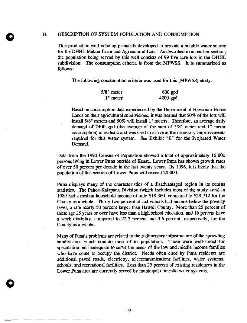
o B.
o
DESCRIPTION OF SYSTEM POPULATION AND CONSUMPTION
This production well is being primarily developed to provide a potable water source for the DHHL Makuu Farm and Agricultural Lots. As described in an earlier section, the population being served by this well consists of 99 five-acre lots in the DHHL subdivision. The consumption criteria is from the MPWSS. It is summarized as follows:
The- following consumption criteria was used for this [MPWSS] study.
S/8" meter 1" meter
600 gpd 4200 gpd
Based on consumption data experienced by the Department of Hawaiian Home Lands on their agricultural subdivisions, it was learned that SO% of the lots will installS/8" meters and SO% will install 1 "meters. Therefore, an average daily demand of 2400 gpd (the average of the sum of S/8" meter and 1" meter consumption) is realistic and was used to arrive at the necessary improvements required for this water system. See Exhibit "E" for the Projected Water Demand.
Data from the 1990 Census of Population showed a total of approximately 16,000 persons living in Lower Puna outside of Keaau. Lower Puna has shown growth rates of over SO percent per decade in the last twenty years. By 1996, it is likely that the population of this section of Lower Puna will exceed 20,000.
Puna displays many of the characteristics of a disadvantaged region in its census statistics. The Pahoa-Kalapana Division (which includes most of the study area) in 1989 had a median household income of only $18,360, compared to $29,712 for the County as a whole. Thirty-two percent of individuals had income below the poverty level, a rate nearly SO percent larger than Hawaii County. More than 2S percent of those age 25 years or over have less than a high school education, and 16 percent have a work disability, compared to 22.3 percent and 9.6 percent, respectively, for the County as a whole:
Many of Puna's problems are related to the rudimentary infrastructure of the sprawling subdivisions which contain most of its population. These were well-suited for speCUlation but inadequate to serve the needs of the low and middle income families who have come to occupy the district. Needs often cited by Puna residents are additional paved roads, electricity, telecommunications facilities, water systems, schools, and recreation~l!acilities. Less than 2S percent of existing residences in the Lower Puna area are cT_entlY served by municipal domestic water systems.
- 9 -
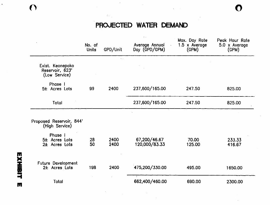
In >C Z -• -... In
Exist. Keonepoko Reservoir. 623' (Low Service)
Phase I 5± Acres Lots
Total
Proposed Reservoir. 844' (High Service)
Phase I 5± Acres Lots 2± Acres Lots
Future Development 2± Acres Lots
Total
PROJECTED WATER DEMAND
No. of Units GPO/Unit
99 2400
28 2400 50 2400
198 2400
Average Annual' Day (GPD/GPM)
237.600/165.00
237.600/165.00
67.200/46.67 120.000/83.33
475.200/330.00
662,400/460.00
Max. Day Rate 1.5 x Average
(GPM)
247.50
247.50
70.00 125.00
495.00
690.00
o
Peak· Hour Rate 5.0 x Average
(GPM)
825.00
825.00
233.33 416.67
1650.00
2300.00
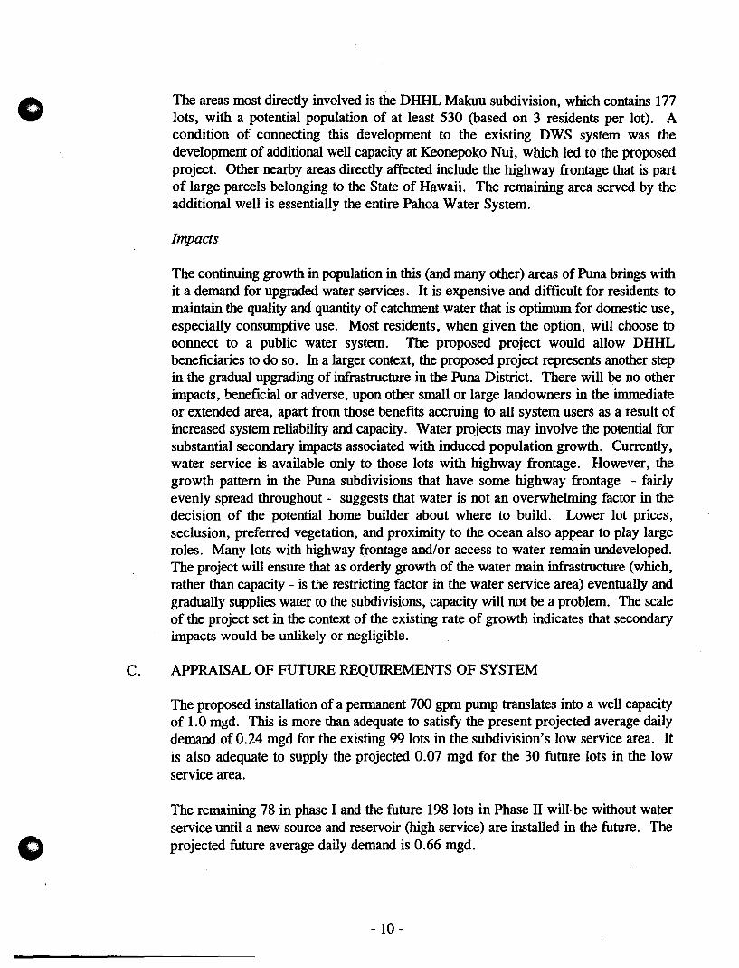
o
o
The areas most directly involved is the DHHL Makuu subdivision, which contains 177 lots, with a potential population of at least 530 (based on 3 residents per lot). A condition of connecting this development to the existing DWS system was the development of additional well capacity at Keonepoko Nui, which led to the proposed project. Other nearby areas directly affected include the highway frontage that is part of large parcels belonging to the State of Hawaii. The remaining area served by the additional well is essentially the entire Pahoa Water System.
Impacts
The continuing growth in population in this (and many other) areas of Puna brings with it a demand for upgraded water services. It is expensive and difficult for residents to maintain the quality and quantity of catchment water that is optimum for domestic use, especially consumptive use. Most residents, when given the option, will choose to connect to a public water system. The proposed project would allow DHHL beneficiaries to do so. In a larger context, the proposed project represents another step in the gradual upgrading of infrastructure in the Puna District. There will be no other impacts, beneficial or adverse, upon other small or large landowners in the immediate or extended area, apart from those benefits accruing to all system users as a result of increased system reliability and capacity. Water projects may involve the potential for substantial secondary impacts associated with induced population growth. Currently, water service is available only to those lots with highway frontage. However, the growth pattern in the Puna subdivisions that have some highway frontage - fairly evenly spread throughout - suggests that water is not an overwhelming factor in the decision of the potential home builder about where to build. Lower lot prices, seclusion, preferred vegetation, and proximity to the ocean also appear to play large roles. Many lots with highway frontage and/or access to water remain undeveloped. The project will ensure that as orderly growth of the water main infrastructure (which, rather than capacity - is the restricting factor in the water service area) eventually and gradually supplies water to the subdivisions, capacity will not be a problem. The scale of the project set in the context of the existing rate of growth indicates that secondary impacts would be unlikely or negligible.
C. APPRAISAL OF FUTURE REQUIREMENTS OF SYSTEM
The proposed installation of a permanent 700 gpm pump translates into a well capacity of 1.0 mgd. This is more than adequate to satisfy the present projected average daily demand of 0.24 mgd for the existing 99 lots in the subdivision's low service area. It is also adequate to supply the projected 0.07 mgd for the 30 future lots in the low service area.
The remaining 78 in phase I and the future 198 lots in Phase IT will be without water service until a new source and reservoir (high service) are installed in the future. The projected future average daily demand is 0.66 mgd.
- 10-

o
D. PROVISIONS FOR SYSTEM EXTENSION I EXPANSION
To provide water service for the lots in the high service area of the Makuu Fann and Agricultural Lots, requires future improvements as follows:
FUTURE PLANNED IMPROVEMENTS
All improvements will be designed in accordance with the Department of Water Supply's "Water System Standards", Volumes 1 and 2, dated 1985, as amended, and will be subject to review and approval by the Hawaii County Department of Water Supply.
1. Future Water Source
Two deepwells with submersible pumps are planned to be the water source. These wells will be located at approximate elevation 820 ft. (See Appendix "E" for future well site location).
2. Future Storage Reservoir
A 1.0 MG concrete storage reservoir is needed to meet the water demand for the subdivision. Bottom elevation is planned at 824 ft. and top elevation at 844 ft.
3. Future Supporting Facilities
Supporting facilities include a control building; the necessary valves and piping; chain-link fence and gate; landscaping; an approximate 8,000 I.f. of AC paved access road and a 16" ductile transmission line from the reservoir to the upper limit of Phase I development, and a 12" ductile transmission line from that point to existing Keonepoko Nui Reservoir; interior and exterior electrical system; and other improvements.
Easements will need to be designated and obtained for future improvements not located on Department of Hawaiian Home Lands property.
E. FIRE PROTECTION AND PRESSURE CAPACITIES
For agricultural subdivisions with lots greater than one acre, fIre flow is not required. However, since one residential dwelling unit per lot is permitted, fire flow of 500 gpm for 30 minutes duration was used in design of this system. This applies only to the low service system, for lots below elevation 520 ft.
Fire hydrants already installed in Phase 1 of the Makuu Farm and Agricultural Lots that are within the high service area are isolated from the low service area and will remain dry until the future high service water system is constructed.
- 11 -

o
F. ALTERNATE SOLUTIONS / SUPPORTING DATA FOR SYSTEM
An alternative site has been identified and studied. This is described in the "Master Plan Water System Study for Makuu Farm and Agricultural Lots (MPWSS)." That well site is planned to be at the roughly 8oo-foot elevation (See Appendix "'E"). However, that site is not developed, is over a mile above the subdivision and the development cost is much more excessive than available funds. Therefore, this alternative was not considered because the DWS's existing Keonepoko Nui well and reservoir site is immediately available, has the approval of DWS and construction will cost much less at the Keonepoko Nui well and reservoir site than at the alternative site.
G. ARCHAEOLOGY AND mSTORIC SITES
The project area has already been graded in connection with earlier water supply projects and no historic sites are known from the area. The extensive disturbance of makes it unlikely that any further surface sites will be found. If any artifacts, charcoal deposits, or human remains are discovered during construction, work will immediately cease and the State Historic Preservation Division (SHPD) will be consulted to determine the appropriate mitigation.
H. ENVIRONMENTAL AND ECONOMIC IMPACT
The DHHL submitted to the State of Hawaii Office of Environmental Quality Control (OEQC) the fmal environmental assessment for the Keonepoko-Nui 2 Exploratory Well in August, 1996. Based on the analysis of the conditions and impacts presented in the final environmental assessment, they concluded that the proposed project will have no significant effect on the environment, and so they issued a negative declaration.
A separate final environmental assessment for the Keonepoko-Nui 2 Production Well and Supporting Facilities has been filed with the OEQC. After completing an assessment of the potential enviromnental effects of the proposed production well and supporting facilities and consulting with other governmental agencies, it has been determined that the proposed project will not significantly alter the environment and impacts will be minimal. Therefore, a Finding of No Significant Impact (FONSn has been filed with OEQC. This appears in the March 8, 1998 edition of the OEQC "Environmental Notice".
1. The proposed action is construction of another production well and supporting facilities on a site that already has an existing production well with supporting facilities and has an existing 0.5 mg reservoir. This project will provide a needed back-up well for the DWS Keonepoko Nui site.
2. There will be no permanent degradation of existing ambient air and noise quality levels. During the actual construction, there will be minor air pollution and noise, but these will not be permanent and will be within the State Department of Health Air Quality Standards.
- 12-
o
(.)
3. There are no known endangered species of animal or plants within the project site.
4. There are no natural, historic, or archaeological sites within the project site.
5. The project is consistent with DWS plans for water source development. Potable water well development by the Department is a permitted use by the State and County zoning designations.
6. This project will provide potable water for the low service system of DHHL's Makuu Farm and Agricultural Lots Subdivision. Phase I has just been completed and has been turned over to Hawaii County for infrastructure maintenance. Any adverse impacts of the proposed project have been determined to be insignificant. The applicant will comply with applicable statutes, ordinances, and rules of the Federal, State, and County governments during the implementation of this project.
N. POTENTIAL SOURCES OF CONTAMINATION
A. DESCRIPTION OF WELL SITE
B.
Keonepoko-Nui 2 Well, State Well No. 3188-02, is located on the existing KeonepokoNui Well and reservoir site, latitude 19-30'-53" and longitude 154-57'-53". The latitude and longitude are based on NAD 83 Geographic Coordinates and map provided by DWS.
The top of the casing of the well is elevation 605.55 feet MSL and the bottom of the well is at -46.53 feet MSL. The topography of the surrounding area is relatively flat, vegetated mostly with bushes and grass. Other vegetation include ohia and guava trees. The ground underlying the site is classified as Lava Flows, Pahoehoe (rLW). The static water level is at elevation 586.7 feet below ground, which is 16.8 MSL (See Appendix "A", Well Completion Report).
ORIENTATION MAPS
Exhibit F contains maps of existing drywells and individual wastewater systems in relation to water wells. There are no streams or known wetlands within many miles of the project area, and there will be no effect on such. The area surrounding the well is mostly undeveloped land belonging to the State of Hawaii. No formal wellhead protection area is required or in place for the well, but in any case there are no drywells or landftlls, hazardous waste sites, or injection wells within the 1,320-foot radius regulated by the Hawaii State Department of Health's (DOH) Safe Drinking Water Branch. Two individual wastewater systems pre-dating the Keonepoko Nui wells are present approximately 800 feet from the well; under DOH rules, new individual wastewater systems would be prohibited or severely restricted within a 1,000 foot radius of the well.
- 13 -
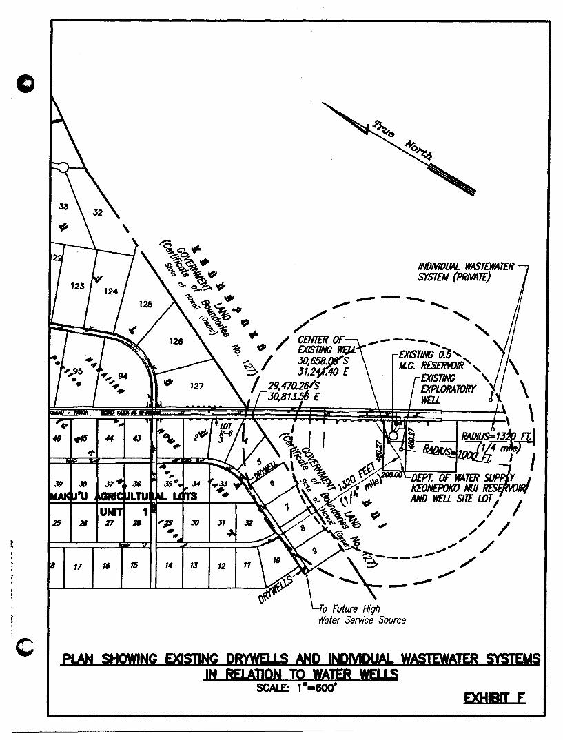
o
~
c
.,.t6
"!'
39
~Gl"" ~~. '%~?t. • ~ GI.~
q.. o~1(,/fI =- .. ',~~ ..
'i3~~ .." '!;,~. .... ~" ...
.."
25 I 26 I 27 I 26 II'J' I 30 • •
'8 I 17 I 16 I 15 14 I IJ I 12
INDMDU4L WASTEWATER SYSTEM (PRNAT£)
.".- .... ----- ....... £X1ST/NG 0')' ~ M.G. RESERVOIR ,
To Future High Water Service Source
EXISTING , EXPLORATORY wru
\ \ \
PLAN SHOWING EXISTING DRWIfl' S AND INDMOlW- WASTEWATER stSJEMS IN REI ADON TO WATER WfI' S
SCAlE: 1-_600' EXHIBIT E

o
C. WATER QUALITY AND CONTAMINATION ANALYSIS
The Keonepoko-Nui 2 Exploratory Well was tested during June 1997 (See Appendix "B", Results of Drilling and Testing).
As expected in an area with little history of agricultural or industrial use, the sampled levels of all contaminants for which state standards exist are well below such standards. The water is of excellent quality.
D. HAZARDOUS MATERIALS
No known hazardous waste sites are present near the well, no active or former generators of hazardous waste are or were present, and no releases of hazardous materials have been reported at the well site.
Appendix C is a Water Quality Analysis Report that details the sampled levels of various potential contaminants. As expected in an area with little history of agricultural or industrial use, the sampled levels of all contaminants for which state standards exist are well below such standards. The water is of excellent qUality.
Water treatment involves the application of chlorine. At the Keonepoko Nui well site, cylinders of chlorine are delivered by truck to the site on an as-needed basis, which is at least several times per year. Chlorine is injected into the water system as the water is drawn up from the well. All treatment is conducted according to strictly regulated standards. DWS personnel dealing with chlorine are trained to be Hazard One responders and are equipped with all necessary safety material, including self-contained breathing apparatus. In case of a spill or release incident, the responders call in the Hazardous Material response team of the Hawaii County Fire Department Pahoa Station. The DWS is in compliance with all applicable laws and regulations related to chlorine, and has an excellent record of safety and preparedness.
E. LAND USE CLASSIFICATION
Land use designations for this site are as follows: County General Plan - orchards; • State Land Use - Agricultural; County Zoning - AG-20-A.
v. SOURCES OF WATER SUPPLY
The basal aquifier underlying the Keonepoko-Pahoa area consists of extensive basaltic lava flows. The Pahoa area has an abundant supply of basal ground water of high quality.
The Keonepoko-Nui 2 well is 650 feet deep and has a steel casing with concrete lining which seals the well and minimizes contamination.
Water quality monitoring by DWS are at such high standards that this function will provide reasonable assurance of safe drinking water.
- 14-
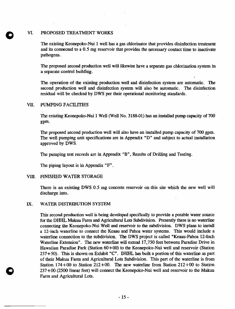
o
o
VI. PROPOSED TREATMENT WORKS
The existing Keonepoko-Nui 1 well has a gas chlorinator that provides disinfection treatment and its connected to a 0.5 mg reservoir that provides the necessary contact time to inactivate pathogens.
The proposed second production well will likewise have a separate gas chlorination system in a separate control building.
The operation of the existing production well and disinfection system are automatic. The second production well and disinfection system will also be automatic. The disinfection residual will be checked by DWS per their operational monitoring standards.
VII. PUMPING FACILITIES
The existing Keonepoko-Nui 1 Well (Well No. 3188-01) has an installed pump capacity of 700 gpm.
The proposed second production well will also have an installed pump capacity of 700 gpm. The well pumping unit specifications are in Appendix "D" and subject to actual installation approved by DWS.
The pumping test records are in Appendix "B", Results of Drilling and Testing.
The piping layout is in Appendix "F".
VIII. FINISHED WATER STORAGE
IX.
There is an existing DWS 0.5 mg concrete reservoir on this site which the new well will discharge into.
WATER DISTRIBUTION SYSTEM
This second production well is being developed specifically to provide a potable water source for the DHHL Makuu Farm and Agricultural Lots Subdivision. Presently there is no waterline connecting the Keonepoko-Nui Well and reservoir to the subdivision. DWS plans to install a 12-inch waterline to connect the Keaau and Pahoa water systems. This would include a waterline connection to the subdivision. The DWS project is called "Keaau-Pahoa 12-Inch Waterline Extension". The new waterline will extend 17,750 feet between Paradise Drive in Hawaiian Paradise Park (Station 60+00) to the Keonepoko-Nui well and reservoir (Station 237 + 50). This is shown on Exhibit "C". DHHL has built a portion of this waterline as part of their Makuu Farm and Agricultural Lots Subdivision. This part of the waterline is from Station 174+00 to Station 212+00. The new waterline from Station 212+00 to Station 237 +00 (2500 linear feet) will connect the Keonepoko-Nui well and reservoir to the Makuu Farm and Agricultural Lots.
- 15 -

o
o
x.
DWS plans to install this waterline at the same time the Hawaii State Department of Transportation's (HDOT) Keaau-Pahoa Highway Improvement Project (FAP No. &5-0130 [24]) is constructed. Construction for both the highway and waterline projects is scheduled to begin in 1998 and both will be fInished within approximately 18 months.
FINANCING
The cost for drilling, casing and testing of the exploratory well is $ 0.6 million. This is being paid by the State of Hawaii, DHHL.
The estimated cost of the production well and supporting facilities is estimated to be $1 million. This will also be paid by the State of Hawaii, DHHL.
XI. PROFESSIONAL ENGINEER CERTIFICATION
The undersigned, being a registered professional engineer, certifIes that:
He has prepared this report and the information contained therein is true to the best of his information and belief; and
The water produced by Keonepoko-Nui 2 Well, State No. 3188-02, the Pahoa Water System, LD. 111, will comply with the State primary potable water regulations contained in Hawaii Administrative Rules, Title 11, Chapter 20, Rules Relating to Potable Water Systems, and will comply with the Rules and Regulations of the Department of Water Supply, County of Hawaii, since this source and system will be operated and maintained by the Department of Water Supply, County of Hawaii.
This report was prepared by me or under my supervision.
Eric N.S. Hee, P.E. Engineers Surveyors Hawaii, Inc.
- 16-

o
DEPARTMENT OF WATER SUPPLY • COUNTY OF HAWAII 25 AUPUNI STREET • HILO. HAWAII 96720
TELEPHONE (808) 961-8660 • FAX (808) 961-8657
November 7, 1997
Mr. Eric Hee, P.E. Engineers Surveyors Hawaii, Inc. 1020 Auahi Street Suite No.1, Building NO.6 Honolulu. HI 96814
KEONEPOKO-NUI 2 PRODUCTION WELL AND SUPPORTING FACILITIES (MAKUU OFFSITE WATER - PHASE 2)
[ffi EGa HI IE lD) NOV 10 1997
ENGINEERS SURVEYORS HAWAII, INC.
We reviewed the engineering report for the subject project and have no comments to off
ON:gms
copy - DWS Engineering Division - Microlab
. .. Wale,. t"ing~ progre~~ ...

o
o
xm. REFERENCES
County of Hawaii, "Draft Environmental Assessment, Keaau-Pahoa 12-Inch Waterline Extension", July 1997.
Commission of Water Resource Management, "Water Resources Protection Plan", June 1990.
Hawaii County Department of Water Supply, "Hawaii County Water Use and Development Plan", 1992.
Hawaii Department of Health, Rules Relating to Potable Water Systems, Title 11, Chapter 20, Hawaii Administrative Rules, November 1994.
Hawaii Department of Health, Underground Injection Control, Title 11, Chapter 23, Hawaii Administrative Rules, September 1992.
State of Hawaii, Department of Hawaiian Home Lands, "Final Environmental Assessment and Negative Declaration, Keonepoko-Nui 2 Exploratory Well", August 1996.
State of Hawaii, Department of Hawaiian Home Lands, "Final Environmental Assessment, Keonepoko-Nui 2 Production Well and Supporting Facilities", February 1998.
State of Hawaii, Department of Hawaiian Home Lands, "Master Plan Water System Study for Makuu Farm and Agricultural Lots", July 1994.
U.S.D.A., Soil Conservation Service, "Soil Survey of Island of Hawaii, State of Hawaii", 1973.
Water Resource Associates, "Hydrologic Feasibility of Additional Well Source at Keonepoko Reservoir Site (DWS), HHL Makuu Farm Lots, Pahoa, Puna, Hawaii", 1996.
- 17 -

o
APPENDIX A
WELL COMPLETION REPORT
KEONEPOKO NUl 2 WELL (3188-02)

G WATER RESOURCE ASSOCIATES
o
Hydrology • Geology • Engineering
Ms. Rae Loui Deputy Director Commission on Water Resource Management Department of Land & Natural Resources P.O. Box 621 Honolulu, Hawaii 96809
Dear Ms. Loui:,
July 29, 1997
[ffi ~ @ ~ ~ ;H !OJ JUl 3 1 ,'117,
:NGINEEffS SURVEYORS HAWAII. iNC.
Well Completion Report Keonepoko Nui 2 Well (3188-02), Hawaii
Enclosed is the Well Completion Repon for Keonep~ko Nui 2 Well.
We have satisfied all conditions of the Pennit and we request, on behalf of the applicant, your approval of a permit to install a permanent pump with a capacity of 700 gpm.
Enc. c:
Please call me if there are any questions.
Mr. Eric Hee, ESH / Mr: Kali Watson, DHHL
1708
Sincerely,
DANLUM
1188 Bishop Street. Suite 6G+. Honolulu. Hawaii 96813-3302 • (808) 528-0074 • Fax 528-0808

State of Hawaii COMMISSION ON WATER RESOURCE MANAGEMENT Department of Land and Natural Resources
WELL COMPLETION REPORT 3I2OJ96 WCR Form
(Check Appropriate Box) DWell Construction o (Permanent) Pump InstaUation
Instructions: Please print or type and submit completed report wiIhin 30 days after wei completion to the Commiuion on Water Resource Management. P.O. Box 621, Honolulu, .Hawlli 96809. An as-buil drawing of the wei and chemical analysis should also be submilled. For assistance call the Commission Regulation Branch at 587-0225, or 1-«1O-46a-.644 Extension 70225.
1. State Well No.: 311-f Well Name: KEONEPOKO WELL ·2. Location/Address: P. OF HAWN. HOME LANDS, pUNA, HI
Island: HAWAI I Tax Map Key:3rd biyJ-5::oa:Por. 1
···':'·;:;-:·::·WELt::· CONSTRUCTION REPORT ....... : .. :::: .. : ......... .
3. Drilling Company: WATER RESOURCES INTERNATIONAl.., INC. 4. Name of driller who performed work: KIHEI AHUIIA 5. Type of- rig/construction: ROTARY RI·~G"'::, ~S::PE=N:n;C=ER;:.;:-~HA:::::RR=I=S -----6. Date(s) Well Construction and pump tests (if any) completed: JUNE 4, 1997 7. GROUND ELEVATION (referenced to mean sea level, msl): 603.47 fl
Wei Bench Mark (descriptionllocation): NORTH EDGE OF PAD Elevation(msl): 603.47 fl 8. DRILLER'S LOG: Please attach geologic log (if available or if required by pennit)
Depths (fl) Rock Desaiption, Water Level. Dates, etc. Depths (ft.) Rock Desaiption, Water Level, Dates. etc.
__ to __ (SEE ATTACiltENT A) __ to ____________ _ __ to_-_ _to _____________ 1
(If mote space is needed, continue on back.)
9. Total depth of well below ground: 650 fl 10. Hole size: 23 inch dia. from 0 fl to 650 fl below ground
_____ inch dia. from fl to fl below ground _-.-___ inch dia. from fl to fl below ground
11. Casing installed: 16 in. 1.0. x 3/8 in. wall solid section to 590 fl below ground 16 in. 1.0. x 5/16 in. wall perforated section to 650 fl below ground
Casing MateriaUSIot Size: STEEL CASING - SOLID & PERFORATED WITH 1/4- OPENI 12. Annulus: Grouted from 550 fl below ground to 0 fl below ground
Gravel packed from 650 fl below ground to 550 fl below ground
1"3. Initial water level: 586,70 fl below ground. Date and 'time of measurement 05/29/97 - 0800 14. Initial chloride: 10 ppm Date and time of sampling: _ 95/29/97 - 1000 15. Initial temperature: 68 OF Date and time of measurement 95/29/97 - 1000 16. PUMPING TESTS: Reference Point (RP.) used: TOP OF PAD , which elevation is 603.47 fl
(1) SteJH)rawdown Test Date 05/28/97 (STEP TEST 12) (2) Long-term Aquifer Test Date 05/29/97 Start water levet 586.66 fl below R.P. Start water levet 586.70 ft. below RP. End water levet 586.71 fl below R.P. End water levet 586 • .70 fl below RP.
17. Aquifer Pump Test Procedures data & graphs (119196 LTAT Fonn) attached? 1L Yes _ No 18. As-built drawings attached attached? ~ Yes _ No SEE ATTACIlENT BAND C 19. Other remarks/comments: (On baclc of this (onn)
Well Drilling Contractor (p. t TER RESOURCES INTERNATIO~_57 Uc. No. AC-5058 ---------------------Signature
e> Surveyor (print)
Signature
Applicant (print)
Date July 8, 1997 oward T. Akagi, Vi Pres PUIIIP Operations
rt:~ ~No. ,f619. -"'7 ~~ Date /~ I~ 1197 : :; 7 7
Date July 23, 1997
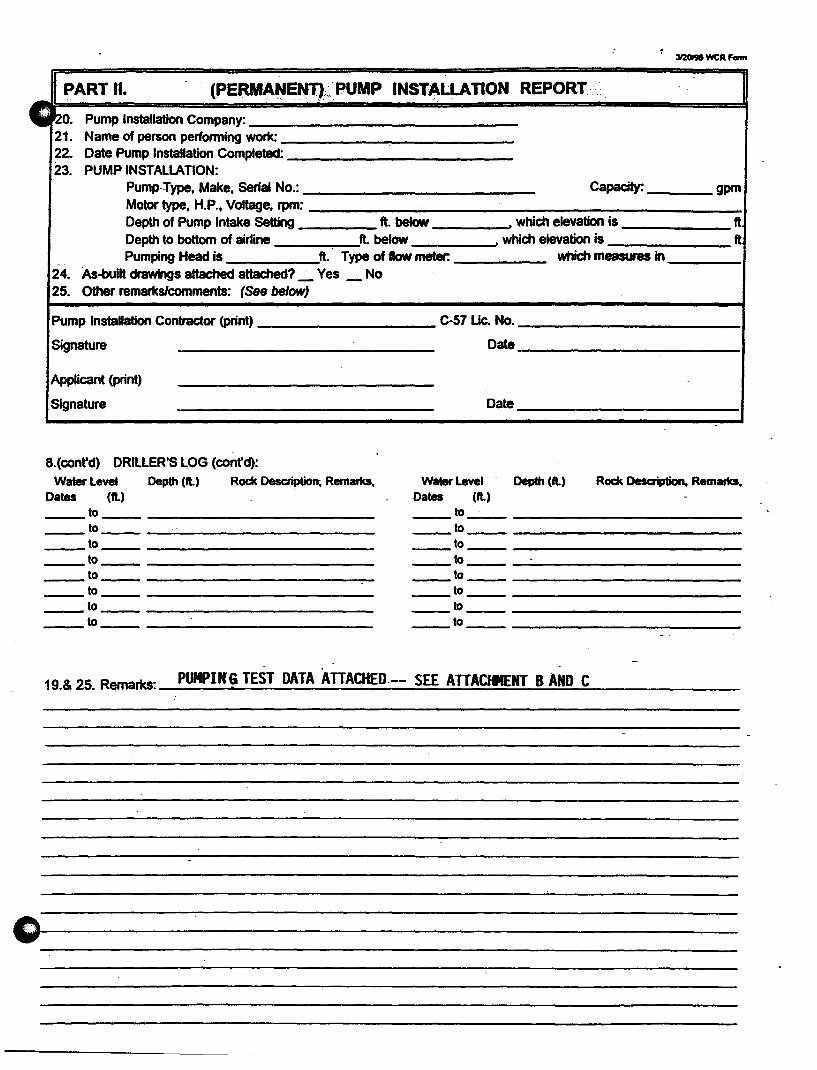
3I20I9l WCR F_
PART II. (PERMAt4ENT),.PUMP INSTALLA flON REPORT·,· •• ·•·
C1 ..
20. Pump Installation Company: 21. Name of person performing work: 22. Date Pump Installation Completed: 23. PUMP INSTALLATION:
Pump-Type, Make, Serial No.: Capacity: gpm Motor type, H.P., Voltage, rpm: Depth of Pump Intake Setting fl below • which elevation is ft Depth to bottom of airline ft.below , which elevation is ft
' .. Pumping Head is ft. Type of flow meter: which measans in 24. As-built drawingS attached attached? _ Ves _ No 25. Other remarks/comments: (See below)
Pump Installation Contractor (print) C-57 Uc. No.
Signature Date
Applicant (print)
Signature Date
8. (cont'd) DRILLER'S LOG (confd): Water level Depth (ft.) Rock Description; Remarks, Water level - Depth (ft.) Rock Desaiption, Remarks,
Dates (ft.) Dates (ft.)
----~--------------------------- -~--- -------------____ to ______ ~ __________________ _
---~---------------------------~---------------------------
_to _________________ _
----~---------------------------_ 10 __________ ------
----~------------------------~- ----~-------------------------~--------------------------- ----~---------------------____ to _____________________ _ ___ 10 _________________________ _
----~----------------------- ----~----------------------
. . 19.& 25. Remarks: _P_UMP_I_rf_G __ T_ES_T_DA_T_A_A_TT_A_CH_E_D_.-_-_S=E=E;....;A..;.;TT~A;..;.;C=fItE=NT.:...:.-;:B=-A:;.,;:N=D:-,C=---_____ _

o
ATIACHMENT A to WELL COMPLETION REPORT Page 1 of2
RE: STATE WELL NO.: 3188-02 WELL.NAME: KEONEPOKO WELL ISLAND: HAW An TMK: 3RD DIV. l-S-08:POR. 1 LOCATION/ADDRESS: DEPT. OF HAWN. HOME LANDS, PUNA, HAW An
PeRths eft.> Oto 24
24to 26 26to 27 27to·31 31 to 33 33 to 41 -41 to 49 49to 52 52 to 56 56to 59 59to 63 63 to 67 67to 80 80to 87 87to 98 98 to 104
104 to 120 120 to 127 127 to 137 137 to 145 145 to 165 165 to 170 170 to 180 180 to 189 189 to 195 195 to 207 207 to 220 220 to 225 225 to 237 237 to 240 240 to 271
DRILLER'S LOG
Rock DesaiptioD. etc. Hard formation - smooth drilling Medium soft formation - fractmed drilling Hard formation - smooth drilling Medium hard formation - smooth drilling Hard formation - smooth drilling Soft formation - fractmed drilling Medium hard formation - smooth drilling ~ formation - smooth drilling Soft fonnation - fractmed drilling Medium hard formation - fractured drilling Hard formation - smooth drilling Medium hard formation - fractured drilling Medium soft formation - fractured drilling Soft formation - tubes and fractured drilling Hard formation - smooth drilling Medium formation - smooth drilling Medium soft formation - fractmed drilling Medium hard formation - fractmed drilling Soft fonnation - fractured drilling Medium hard formation - fractured drilling Medium hard formation - smooth drilling Soft formation - fractmed drilling Medium soft formation - fractured drilling Medium hard formation - fractured drilling Soft formation - fractured drilling Hard formation - smooth drilling Medium soft formation - fractmed drilling Medium hard formation - fractured drilling Medium soft formation - fractured drilling Hard formation - smooth drilling Medium soft formation - fractmed drilling

o
AITACHMENT TO: WELL COMPLETION REPORT
271 to 323 323 to 335 335 to 340 340 to 345 345 to 353 353 to 362 362 to 371 371 to 384 384 to 389 389 to 392 392 to 400 400 to 407 407 to 412 412 to 416 416 to 423 423 to 447 447 to 456 456 to 476 476 to 484-484 to 492 492 to 507 507 to 521 521 to 524 524 to 529 529 to 555 555 to 575 575 to 593 593 to 600 600 to 622 622 to 650
WRY -fJ7/01l97 sm
Medium soft fonnation - fractured drilling Medium hard fonnation - fractured drilling Hard fonnation - smooth drilling Medium formation - smooth drilling Medium hard formation - smooth drilling
-Hard formation - smooth drilling Extra hard formation - smooth drilling Soft fonnation - fractured driIIingMedium hard formation - smooth drilling Extra hard formation - smooth drilling Medium fonnation ,.; fractured drilling Medium hard fonnation - smooth drilling Extra hard formation - smooth drilling Medium fonnation - smooth drilling Hard fonnation - smooth drilling Medium soft formation - fractured drilling -Medium bard formation - smooth drilling Hard fonnation - smooth drilling Lava Tubes Hard formation - smooth drilling Medium fonnation - fractured drilling Medium soft formation - fractured drilling Medium hard formation - smooth drilling Hard fonnation - smooth drilling Medium formation - fractured drilling Medium hard formation - smooth drilling Hard formation - smooth drilling Medium fonnation - fractured chiDing Hard formation - smooth drilling Medium soft formation - fractured drilling
Page 2 of2

o
o
ATTACHMENTS PUMPING TEST RECORD
Test No. f ~ ¢1 ,19~
Well Name /({.., 12,u t! (Jt'"f() 0# AI H / .2.. State Well No. 3/ Y'Y - 0 'L ; Project Island /(daJA I r ( ,
DEPTH (Below Ground Surface): ELEVATIONS (Mean Sea Level):
Solid Csg: Y-' I Perforated Csg: 6...£1 Ground Surface: 619.3. t 7 ft.
Total Depth: <451 Top of Casing: ft. Rotary Table: ft.
Depth to Water: $11'6, 70 * Bot of Solid Csg: tA-,"",'") Bot of Perf. Csg: - 9 ?~-3
. ·Remarks: ,fe £ Ti.,e " £ Phi. Bot of Well: - '12,'" 3 Static Water level: "I- /6, "'} ) TEST PUMP: DRAWDOWN MEASUREMENT:
Type: /D" 1.. '..J&» 1M.flLlntake Elev: - .,2.,. . .,-J C Manometer [J Pressure Gage • Beet. Probe DISCHARGE MEASUREMENT: III Rowmeter a Other ______ _
Elapsed,. Dati:
TIinI' !Ii.,
(miaJ. : : T ... :
S-/-2.'l/((") ~:;"A q-!~,4
'-
_C( !;J.o A
_q"..1o/}
fJ'M",J "'!3S'
15'_,·..L q:..,~
-::J.D_/ oJ q: -)0
:3,., .... ~.J ItJ=t)()
'/0 'oJ /0:10
.,-o_:..J 10.'.10
bD ..... '.,J /0: )0 ,c_,., 1I;~o
/..20._ '.J 1/: 7,0
/fJ'O J.2:JO~'
.;J. '10 /:Jo
=SOD .2: 1L'
H;pc> 3: 3('
~.J.O ¥~ "30
~f1f) S·: ~c
,,{O 6: 3"
60a , : 30Pm
Water Resource Associates FormPum2
:~.
RIta: (pDt.
,9
0 0 <fA,
/0/'" Inn"
LODfi'
LOO.:l.
Leu? /{)()~
toni'
lef)·'S'
,,, I~) -5
If)rJ~
J 1'''' <:"
/010
1t!J 10
1000
100";
JOt.} fI('
joo';'
C.AirD 0IJseInd:: AdPIstId:, I:, . ::.
alOtw I:::'~ .. DIIwdowIa: ~ .. I: ,., 'Re.dii(: .(fiett. IfiItt I.e . flct;:: .... :::.
"({~ . ..., ~!;',. 7
,..,m" ?
fr Puwc~ 591.A.)- ~.SS" ~/.lq ~.l\-q ,5""'11. .J..O 1+,5"0 ~J,.l.l. '+-sl I s-l/,")" 'I 1\ 5',,"
~/.;I..'I ~5t..t
~1. 2< 4,5:1{'
", I,.J.¥ '+ 5'+ ~-'il, ..4(. \\-.5~ ~/ .. ?O ~ l:O
5"1 J,.-" J \:\- !('\ 5"'il .. ~ 7 '4-1r1 <"tl,)? ~.~~ 5'1/, <I 2. 4.1J. 911. -I J.. !t.l.), .c;·U, '11 U;1~
M/,4f 7 LtJl
: •.. CIIIcIridK: :r., Cand;..
<;: fppart ': .: ; (Of) : (mhD&'25°C)
~ .. -1&>-IIII_~C
6K
,,~11

Pumping Test Record (Coot'd)
C Well Name: 1(el'};c.Ieloko A&./ .:2..
o
Elapsed Date
rune &.
lminJ .~/I~97 htl:.> ~!3(lPIf1
7~V '7!30
} 8'0 IO~3{)
(("'1.0 }/:30
'! (Jo 5'/'J'J('"I I 7"t JlcA"
ql:o 1:·30 A,..
1(/2.0 ;1.: )0
} o~o 3:30
II'fC' 'I: 30
1:1-00 s-:3o
IAIA.' "::;0 /3).,0 ?:3c.;
i..Jff'IJ ~'30
1"..,0 1.' 10
1..,-00 lo!30 /,1;.0 I}·') 0
Jb~ j~: ~/,II(
Ie:, 80 /; jc.'
111./0 ;1.! 3c
j~f)O 1:·.J()
~6,J 'I,' 30
It; .;L.e> ""-'"3 (' /t]9'c' h; ", :;l~ 'ft.' 7 : 3.:'
.2. I ()o >i' ~ :5 "
.2Lf,O 9: 3D
;J.J.:z..o /0:30
:2.2.. S"O 11:3~
- ",-A/fin
~'~D j"z: 3(.lA""
Water Resource Associates
FormPum2
PiIInping [J Airiine
Rate elOYW (gpm) ReadiIg
/000 <91,'19
IflOff) ~/, 'lK
/OIP< ~/."]
/0(10 ~/. 'I)
Cf5'O ~/,~-O
leoti ~/"y
/O()~- 5"f::t.() ,
ID~O .r92. 01
/oc-~ -n;'.ev /tJo '> 5r"f.2. C")
/00<" ~.2. ,I(
10c>"- ~...,;z. ,., /oo~ ~~:z. J~
/ f)() 5' #)'12·/1 I£) 1<"" .5'1:1 IJ
/0/<" ~~ " 1£1/0 .-;-'9..t ,I
/010 57~, )1.
lor) !:>-~.z.·.I'
1& /$ .5f.1.IY
/0 (0 !T9~, 10
10 I t1 5"9~ )~
;(9,0 59.1. .Ff
I{)')~ - S'12.., /l...
lOll) ,~q-l.. ,'I
J VI tJ .(\'cp •• /)'
liN 0 <"Cf).. '"
If) /I} 'o-Y..,2 J)
;-c
/0 oS' 5-Y~1 ")
State WeH No. 319'Fr-() '- Test No. I -~---
Observed Adjusted
Drawdawn Drawdown' SampII· Cblorides T~ Cond.
Ifeett Ifeetl No. (ppmt (oF) Immhos25.°CI
4-1q '2 I;. thy" 100
4.l1 '-".11 ij.i1 ~.qo
l;" J.1f t;: ~i C;~
~.'l,'
.".~lf-5:~1 S,W -
L;'",Lf'J ~.~ ~. b (3 J;(D 100
~.4-q '.
5;~1
l;; 4-l t;. tF1 (,'t\.,
;",4-1... t: ~ c:
6.4-4- .
~ltO
.t;4-0 -
~~ 5.4-l . .elf. If "t' ~ t~Q IDO
-'
_t:;.4-~
5.4-6-5.4-1
,.. u..7 i .,
Sheet ..l.... of 7

Pumping Test Record (Cont'dl o Well Name: /(e,OlVo/"tfC AJ ~ ( \
o
Elapsed, Date
rune &.
(min.) J)f,-A, .;l. C{ 00 1-'30 BhI
;1.t(~o :1-:.30
:l.c);.D .3;3v
~S'"g-t) 1!jO
:2. ~~() 5":.30
;J.. '100- (,:.30
;I.' w 7.':]0.
~~() . 9:3D ,,2¥~O 9~5o ~,~O /0:30
-3000 II ~30
.-- .30hO PAl
/.;1. :30
,3/~O /:30
3iff'O .:1.:.3 ()
3.::z~O .3:30
~ 300 1.f;30
'3:; hO <: 30
-3'-(,2..0 b: 30
_." " (1'0 ?:.)O
~~S-t{O 3";-30
3000 1/30
3b~O /(}:.Jo
~7.l.0 1/;.30
~ 37 )-'0 jPl; 3£lAlh1
·~)(t(O 1:50
3100 ~;30
39hO 3;.'30
1020 '(: ~o
L(O~O ~"':·JO
Water Resource Associates
FonnPum2
~. [JAidine
Rm, JibTW (- R"'"
/010 591.~
/010 ~,,/, w /0 If) ~/,.g9
/ i:J I.e) 5'1'/,90
/0/0 91/193
/0/0 ')"11.1'1
/01)..,- <'II. Y'I
/tJ ()5 'it!( I. ~I /VIO ~f/r t~
/0/0 ~-r:r /. Cf Cf
/0/0 ft/, ?s-/CJIO .l(Cf/" '13 /OfJS ~-Y/,9i
/(;)/0 c'5'9/,91
/C)5' "'f9/,92.-
jlJ) /,'5"' .<"9/.91
IL" , . ., ')91 qy /t:)I-i" 5"9/.91-
.1) /0 "I,Cf'f
I" 10 5'9J,q 3 10/;) "'-91, 'l1 /(J 10 79.1.,00
/0(1-< 5'ttl 'Cf 6/J/< 11-,
,
/1"0 79/.'1'1
100 .. .:;'1.2. ,oci /iJ "..., ~)"Ol
,0 j <\" r'<i 1,'1" IO/~ 5Cfl. " I J () I "f' '7'1'-,0 cJ
State Well No. .3 i ¥¥ - t!J ~ Test No. ~~/ __ _
. OballYed· Adjusted·
Drawdawn' Drawdown' . Sampia:: CbJoridu: r .... Cond. <.
(feett (fieU PIlL. /ppmt.' . (Df) /ImIIIos 25DCI
£Ig c:tK r;3" K".lq C;lV
i:':d~
t:".,l4-~ ).I.f-
5,.1.\ S 6 < .c~:': /00
_S",d.~
~1J.'t
~)5 J::; ~~
J;:~I
.c;'".~1 (,5-D
~D !<" .~,
.~~~
,<~
~J.* ':::1~ ~ 5 ~~.P 100
'\: J.~ c:;",30
·_trJ.q
?'/Ol.q t;AL' t,C(~
~ ",I
~,.l"
Ii: :; I T;,3 ()
Sheet.3 of L
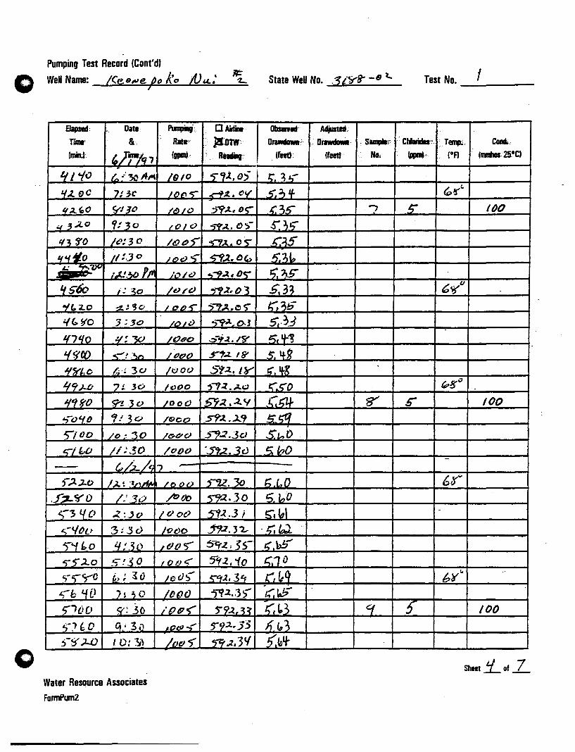
Pumping Test Record (Cont'd,
Well Name: I(es~e be ke tV 14#' J
Elapsed; Date. Pinpini' ..
rlllll: &; I Rate;'
(minJ. ,h-Ie;.., Igpmt·
If' 'to t.. .: '3C AI'( /9/0
'1.1.. SC .'}: 3C Il)~ -s-11.4 ,0 'i'l J" /6)/0
q 3.,4,0 9: 30 ;Ole}
1(3 3'0 Ie: 30 /ot:J;
If '1 *,0 /1 : . .J 0 J£)e) ~ £: _~.O'I
;.(:.30 Pp" ;';''''1 I,;)
lfs60 j: ~o /0/0
-1(.2.0 ~~ fJo / ,,,,-r t.(~ S/o :;::10 /o/,:}
1(7'10 ¥:-w /0190
Lff1C() ..... -~.')/') /Pt?()
~fjj'''-o k~ 30 /tJoo
'1tj.)..b 7;. .30 1000
1f1ftO 9'!.30 /000
~()~O ,! 3GJ /900
5"100 /0 ~ :30 /(!;6'CJ
&)"if:.,D Ii ;~~o /Oo()
- tv/..i..A I., ,-"" .J-t) J,J. ~ '~n~
.f~~O /.'30
~>qo -Z~.)o
<'100 3;'30
5''''11:.0 I.f:30 ~2;2.0· _~:.50
';~ <) yo ~,; ~o
~b I.{O )~" 0
5'1() 0 9': .30 ,,-) {; 0 C;' 3" 6-$' )..0 ID:"!:;\
Water Resqurce Associates
FormPum2
/(} 00
ft~
IQot>
/c>c>o
~&tJ"
I ()I':J < Ii) ().;-
JD()()
/ () I!' tt)'
AO(JJ .;'
/0" 5'
(J AidiIe·
: )I:DTW' : Readinr
5""1i.,0)-
.r-'1~.CV'
:J~-t~ D~
-;9'...t. () ">-
~A.O~
5"f.l.O" ..,'"'9~. o~
~"'..l,O.3
")..,.~.o ~
.,-t;'iL 0.1
":;-"".2.. If/'
5'1~ IS'
S'l2..IY ,....,~ • .4«:)
!:>7~ .2.V
Sf.z.. . .J..9
5'7.2.3Cl
-S'..l.3v
,-U.30 ~.30
5'i~.3 ; .19.2. J 7..-
~9..z, ~S-
5"'(2., '10
~ctl, 3~
-jTi.2 •. 3)
~9~.~~
~9::z.·35
5"9~. 3'1
State WeH No. .1iYS- -6 t... Test No. I -----
O/lsemd' Adjusted.
OrawdaMt·: .. OrawdaMI : SampIa;:; . CIJIarida-·,. ·.T~ . Ca.
(feet): (feeit No. -;:. (of) (1IIIIhas. aoel
1:. 3~
. 5'.:; if ~~ .. ,;: 3_1) .., 5' 11)0
s"'l,.a;"'
.C~5
5.7,10 r;."S" So .3~ 6~t.J
K.1b s,.?J.:3 6. 'I-'! S. 4-R ~.1f-g
r;~t;"o ~B''' '.
_Ct;1.l- fr ~ 100
5~ S", t> Ii /nO
t;.l.D 6Q"
5 InO
~. to' -
'-~~ l;"bS' 1;.10
r"/~~ 6¥~ -J.,'; ~
1;,~3 q -; 100
h~1 (,fo'l-
Sheet !:L of .L

Pumping Test Record (Cont'd)
" WeUName: /&9-C .. J O pu.< )t:-3c W ;
Elapsed: Date: ..
rllilt::,· .. 8(,· ..
(miD;!. .. ," ", ~~fl1') .
5~ //:30"~
~-tj 1(0 /.:lo!Jo 'Ill "000 ( .!3i>
'Inc GO 2..!1cJ
{'I",o .):.3 CJ _.
6 IS"'O if:~t:I
" ~l{o ~:IJt7
b30D b': ~tJ 6.3'0 7!3" ~ '1:1..0 <;;-! '$l)
, '(~O tt .r 'Ji>
- 6c;-'iO iO!3C
(b~OO /{:30 - G.h/CZ."\
"'0 • /.;t!JelPl'f
''';J..O 1;3" ~Z~(} :l.! 10
/'rt' 40 3:10 1,900 ":10 ~9bo ~!iO .,,2...0 ':-30 '0 $'0 7:10
"1.10 9':30
77..00 If .'30
5W . I"", ,',J ,!.)]
..2. q: 3\.
3 't~3.3
if 'I] :3 'I ~ '1~3')'
Water Resource Associates
FormPumZ
PinpiJg:. .... .. O.AirIint:" Z·.rtatl ::·:.: }a:OTW: . ::. . (pilI.' •.. ):ReadiIt::· . . . . .
/t1d c 5:"T~r.~
Ie/DO ~.:l • j.tC"
?tJflS s-J;t ,liD If!) 00 .~~.3~
/DOO ~2r3£.
1 ~ f!)';- n:z.'{~
/~ CJ5" 59.:l.~
I" 05' 5'i:l..4[0
IDD "5' ~2.q,
I()IO ~9.1,f.s
/0/0 .. t;'Y:l. ~7)
fOil) .~;t.'1~
./O/~ ~)t,t('
/00-> ~-r;;Z.33
/CJo~ S'l.%,3t.f /010 .,-t;~. 3' /0/0 S-'1:t .31 /JlJln ~..t. 38' /010 "'9.:l,$~ I'I'D> 5'7 .1.-. ~ -,
/O/J-r- 5*9:z 31
/0/" 'S"'f.2. •. 3 " IOO~ ~-rr:1 3 V
Pu ~ /.J J:-'Cj
:;'~S:3V~ ~S",~c
S-f{'.~)
~~b " ~&t. 88
("
State WeB No. ?/8"lr - tY"l... Test No. ___ 1=--_-
OIii ... I::':·· AdjuItIIt. ,}:::.:. . ': .. :: . -::
Dia ..... :.::·. :: 1bwIIaIIa::: \~:::: :":·ClibiIIIs:::: fT_ ConIl. <:((111)· .
::: ... t . frjpnt:.~: I,..:;:,:·.·· .::. : ~:: (.f) : /mmhDl.a-CI
..... .-:::
~~q
~Ifoe 68'f:J
.1;,1 D 5;{ob
K. ft?" 5.1 0 .(',tA t;;1V
.~.1' ,~
.6.15 /t:J 5" 150
5:go ,r;1K ~~1'1
-s". ro3 6~o
St.~ ~~k ~bq~
s:~t 5.,,1 5'51 ~"-9'e
<. b' ·K,bV .r.l,,/f 9--#1. ~N' n,,I! gee '...0 t/ e,;Il!! v
(. ~ l"
0.'1' . tt~ • 01\-d
Sheet S- of 7
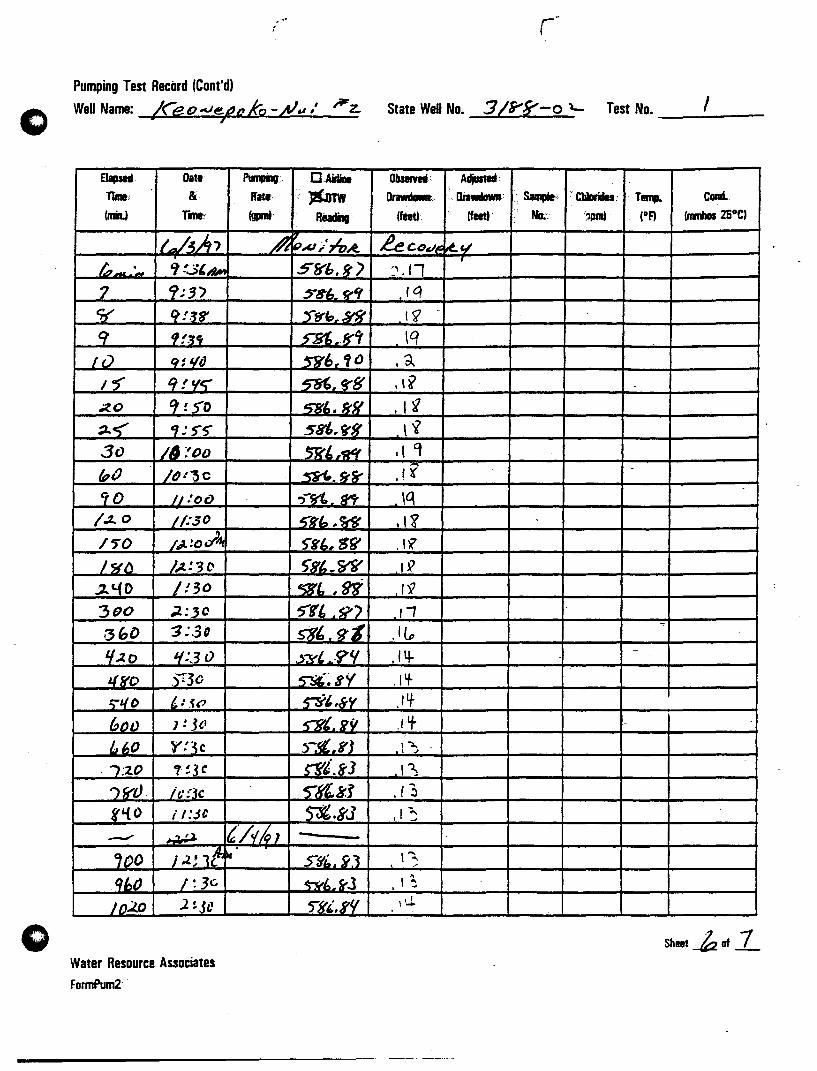
o
o
Pumping Test Record (Cont'd,
Well Name: /Ceo--.JetJoto -#&1,' /Fz.. I
8apsed. Dati ~: rune:: & irati (miL) rw.: (gprnt.
ilAJt, ~ IO_.~ Cf !..3'"".,.
7 9:3)
11' 9 !.J8'
cr '1f.Ji
LiJ J1S I/o 1'5" 'i ! 'Ie; ~o 't !SO
~~ 'i:S'~
30 /~ :'00
(pi) /()!~C
90 II :o{) /.2. 0 1/:,30
/5"0 I,? ! () .:lA, I~(l J,%! 3 () ~C.(O /!30 300 ;l:3C
·36D 3:,3D
If:z. 0 ~:3()
JL~o sr30 :;1/0 1,: .~(?
(,O_1l ) : .J'}
blJO Y:3c /:2..0 1!3C
.., $f"O . It: !'3c f'{O i t:JC
..- ~ (/v!G, '00 i .2; 1t-~ fll,iJ / :3c
Jo,),J) 1 ~jC
Water Resource Associates FormPum2 .
C.Anne .•. J&mw
RiadiIg
~..u;:n~ 5&'b. ff ')
$8'~. ri
5"ff"~ ~,8"
~6/f'o ~~g'8
~'.fff/ 58",i"B'
5R't~
~.k~
.,-~ 1n'
5~b,W
~K'-, S~
S"8'pW ~"W ~t' .~") _S"8,_.g-Z .j-yl. ·(j'lf
~~8Y
~{,'NY
~'·KY :>Jl,YJ ~i.8'3 5"'~k.j'
~.5'J -S'~~. y]
5Y6 .. rJ
'[{'.K'!
State WeD No. 3/9'5"-0 ~ Test No. __ , __ _
Obsemd: Adjusted·
DrawdaMt.:. .. Diawdown: •.. SIm!*: ... CbIDrides. T .... Coad.
(feet) (feed·· tla-.·. ',pant . (oF) (mmhos25°C)
P.eCDcI~ kv ., /1 .- ,
,Iq
11 \q
,a ,I¥
· I ~ \i
.( 'l
.,? -
\q ,I~
. 'l? 19
1'9
Ii .1 (p
,14- -
· I If-Ilf -
.1 't - .-
,-:>. , J
-
I~ , .., .. ~ " ~
\~ \~
• J
\U-
Sheet -k of 1
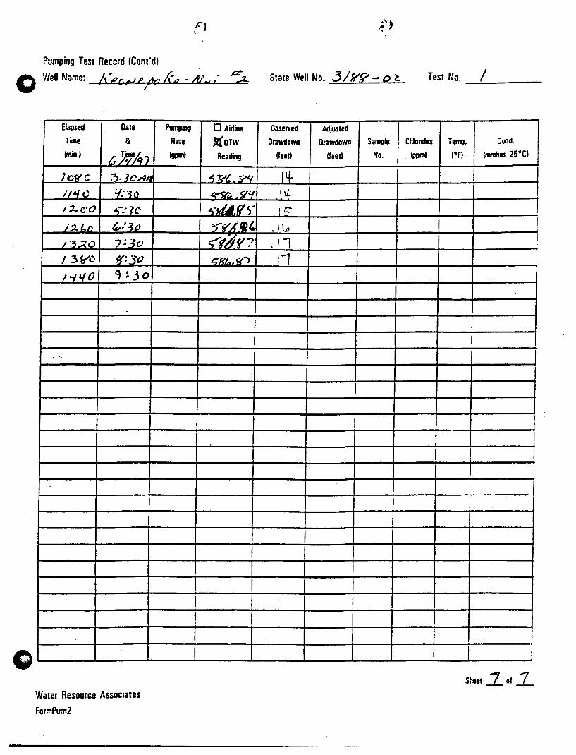
Pumping Test Record (Cont'd)
o
o
Elapsed Date
TIITIe &
(minJ 6~A-:> JOffO ?;;]CAI'
}/'10 '/:30 ,:)....cO ,,:1c i.:.t Lc ~:30
1:3~O 7!3o
I .3~D ~:3P
/..,,,0 a,!.3o
--
.
Water Resource Associates
FormPum2
f]
Pumping o Airline
Rate ~OTW Igpm) Reading
~-:v! J?<t
"'~~ fly S-~~r
~~~~I' ~f~f7 ~B/",~
State Well No.3 Irrf? - Q ~ Test No. I -.:-----
Observed Adjusted
Orawdown Orawdown Sample Chlorides Temp. Cand.
/feetl (feet) No. (ppm) IDA (mmhDS 25 D CI
.14- I l't le::- I
, \ \..,
, /1 !1 I
I
I !
Sheet~af 7

e
Feet
TIME-DRAWDOWN CURVE Keonepoko Nui 2 Well (3188-02), Hawaii
Date of Test: May 29-June 3. 1997
/" Head· 16.7 It. Pumping Rate: 1000 gpm
-3 !!! : i ' .. ,
-3.5
-4 -
-4.5 -
-5
- 5.5 -
Grd EL ,-i 603.'5 ft.i iii :
TO - 1650 ttl. 1 ,
, i
!
j ;
! .
i : ! ' i ! ! j
i '
! i ~ 1 ~ .
!
! ;
, ! j l I , i:
: !
Feet o
-1
-2
\ d-- -3
-4
-5
-6 -t---r--+-i -1-1 -H~I i 1 ----"..- j : ; : ,-ri- iii,' -6
10000 1
Water Relource Alloclatel 073T001
10 100 1000
Time since pumping start,ed. in minutes
-Drawdow~ ~
()

e
Feet 0
-0.4
-0.8
-1.2
-1.6
-2
-2.4
-2.8
-3.2
- 3.6 -~ -4
-4.4
-4.8
-5.2
-5.6
-6
0.01
TIME-RECOVERY CURVE Keonepoko Nui 2 Well (3188-02), Hawaii
Date of Recovery: June 3-4, 1997
, I; t
! !
i!
! j
, i
0.1
l I
l!
i i ; ~ ; ! . . '!' .
I 1111 ! I: I,
! i j' lIt I ii, , II!
rQ~Pl?1 i I ! I! I! , I, "
I r 11111
i'
I , .! iii
, iii! 1 , Tim1e , ~Tt ~J: 5160
! i II . It! j
i . I I' ! !
1 10 100
~ ! !
mln~ "
Time since pumping stopped, in minutes
- Recovery (ft.)-j
1000
Water Resource Associates 073TRC1
tt
! i i!
;! \
i
i I ! ~
! i l;
9999.999

/1:.:..L ..... .z.. 5i,,;:c. ?:¥C·-U,.b~) 7!V>-9.t:,"J', 7:S-0-9,6~i 7:SS-'1,l;~ 9':",-'-1.6,11
5~L:,.,.).:sf 5~t,·c.- ")/'(;- ~i,"'.1 7:s() - S"i"'.'~ -J: S5"- >8'~."6.; ?'C? - S8'£. t.~ o Pumping Test Record (Cont'd) Sl4-./' fe~1 ATTACHMENT C
WeI Name: /(el!J.ve/Joko -;Vu r I I~ z.. - State Well No. Test No. _.=2...~ __ _
$c/''..J~f i{:
EJapsed Date p ..... o Airline Otasefyed Adjusted
rlllle ¢rk' Rate ilOTW Drawdown Orawdown Sample Chlorides Temp. Cond.
(min.) Igpm) RQIIinQ (feet) Ifeetl No. (ppm) IgA (mmhos 2soCI st~ !CD ~fI'"t.1..
.2.,.,.; • ./ ~.·O:A- ")&:.O - 5"8", g t. 3,/1: -..,- " 8': cO; 7 &:..::1- C"H'f.8" 3 ;z. 0
/5 " g-: IS'" 7i>'S ~ <<is'" .~ ,;1..' ~ ~ " .v:.:1.~ ."c; S"'lt>, lJ if 3, .38' 68"°
3>" g': 35'" 'JtJ S"g',!lS' 3 3;:t.
q~ It ~.'f5' 7h -;-- ~9().O'> ~.:J1
52' " $'~ 5S" /bS" .5YJ'f) () I 3 15~-
~o" '1:00 )~~ ~~,99 :3. 33
6S' " er .' oS- 975' -r9/,5g l/ , '1.2. 70 ,I ar: 10 , 30- ~/.VI '/.7') I')'I'~'"
ff'C> " ,: ;:z..o ~3b SY/·3? tL 73 68'°
9() " t:t:3C 9.2. " 5"9j, 'fl LI,7>
/ If) f') " 9 : '10 ttso .~/, 'I:z. 'If 7(,
I/O " 9 t S"o 930 ~),CII -'LJS' 1;;1.;:' II }o:"o 9,l.S 59/,'1). 4 . ., Ie rc-/.l..~1f /f):()~ //1{0 S'93,'0 t,. 1'1 /30 " }O:FO 11,/0 5't3d,r ') I ()1-
L'lJ2. 1~.·;2.0 LL"'lO 5tt~, fr;2.. 7 "
~~c
I"n /t.): 30 If 3S' ~3 S'1 7.2.3 /(,,0 lo:<{t) 1/4/ {) 5"9!J. ~ 5" /,-Z,
)JO lo:~O II.,S- 5'1'1, t>2. 7,.3 £, - -
ItlO Ir:()O I/~O ~"'.o7 7. if I '.$.
I'J§' jl:~5 L,/o§" :5'''1' "} I cr.z 1/, ..2..~
190 - InlO j'lIO 5"'fS'i 3~ J),73 ).00- II: ;J.O I'f (!)b ~-99f, 8"3 12. J 7 /).10 il: 30 ILJ05' _~,--. II 1.2 &.Ie) bS'''
..;t.2.o 1/ :-1{0 ,qlO ~ 33 1:2,1:7 ~30 1/: ~o ;110 599,50 J2.ffY ~ 1~;jJlI<
~..,o il-:~o 1'110 .S'9Q, 6<;- 11. 1 'fI .0=
o {ecJ;j,','- t/ .z..tJ, , j:Lt 0' :$'T{', () 0 rl. (,.(, .
"t.
.1 'i 1.. 1.2.· c" _-__ ~"-!'S, .1<", .2.'(J 1.2!~3 '
Water Resource Associates-----xr~.::..5.:.;, !r::..;u::..
FonnPum2 ~2~~~¥ ____ ~/~~:~cL¥--------~£~~7·~3~O - .:>-:rl" 7(;J_ ,1.. l.f £ /2.:0)
/- 1.:37 Sheet _, of :L
+·~5 J. -..L 6/, ' •. UT @ S-S"6. ,,)1 t4~~ /. / L
, - • ..J. c.1\.e. (' K~ 1-. 3... ~,A)f.·1 /.;l..' 10 -.0'1 _ • 0.li
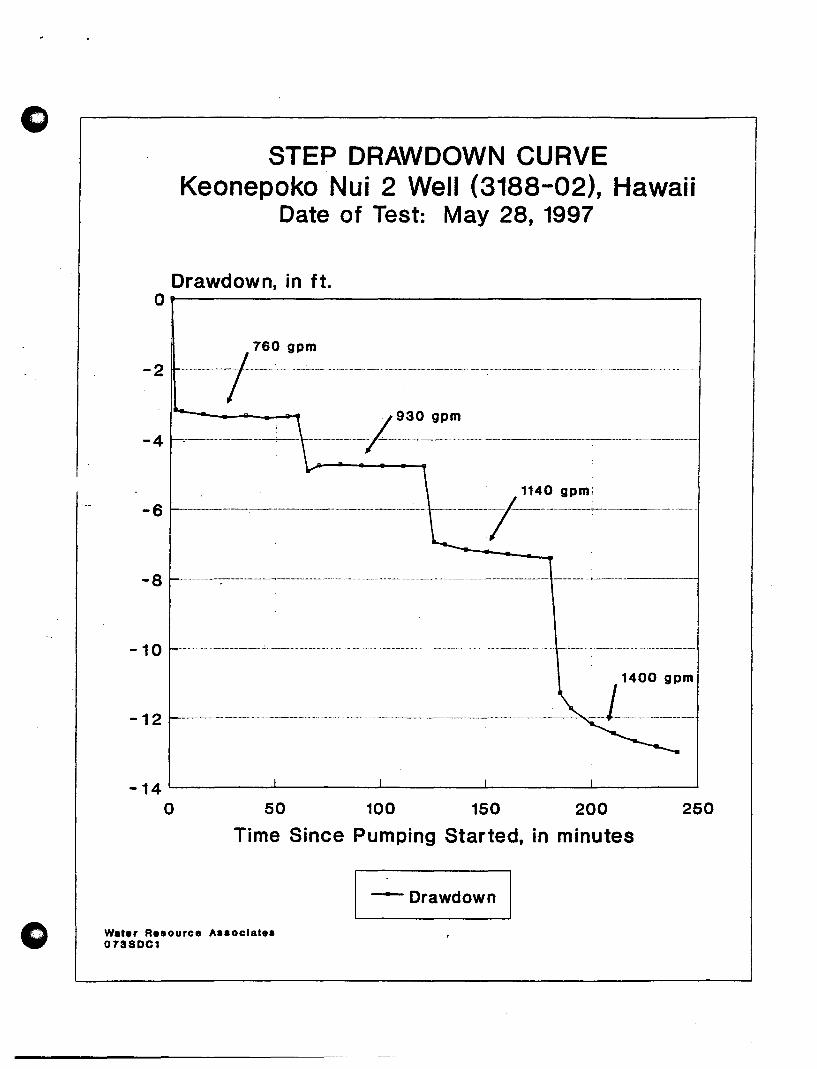
o
o
STEP DRAWDOWN CURVE Keonepoko Nui 2 Well (3188-02), Hawaii
Date of Test: May 28, 1997
Drawdown, in ft. O~--------------------------------------.
-2 ----r-~~-m--- -....... ------------- .. )
930 gpm
- 4 ~-------------------------~---- ------------------------ --;..------------------------------------------------------------------------------------------------
- 6 ---~-----,-~------------- ----~~~-----
- 8 -------------------------------.-----------------------------------.---------- ------------------------------------------------ ---------------
- 1 0 ------------------------------------,------------------------ - -- -- ----- --- ---------------------------
- 1 2 ------------------------------------------------------------- ------------------------------------------------------------------------------------------------------ --L:~~: -14~------~------~------~------~----~
o 50 100 150 200
Time Since Pumping Started, in minutes
Water Resource Assoclste. 0738DC1
-Drawdown
250
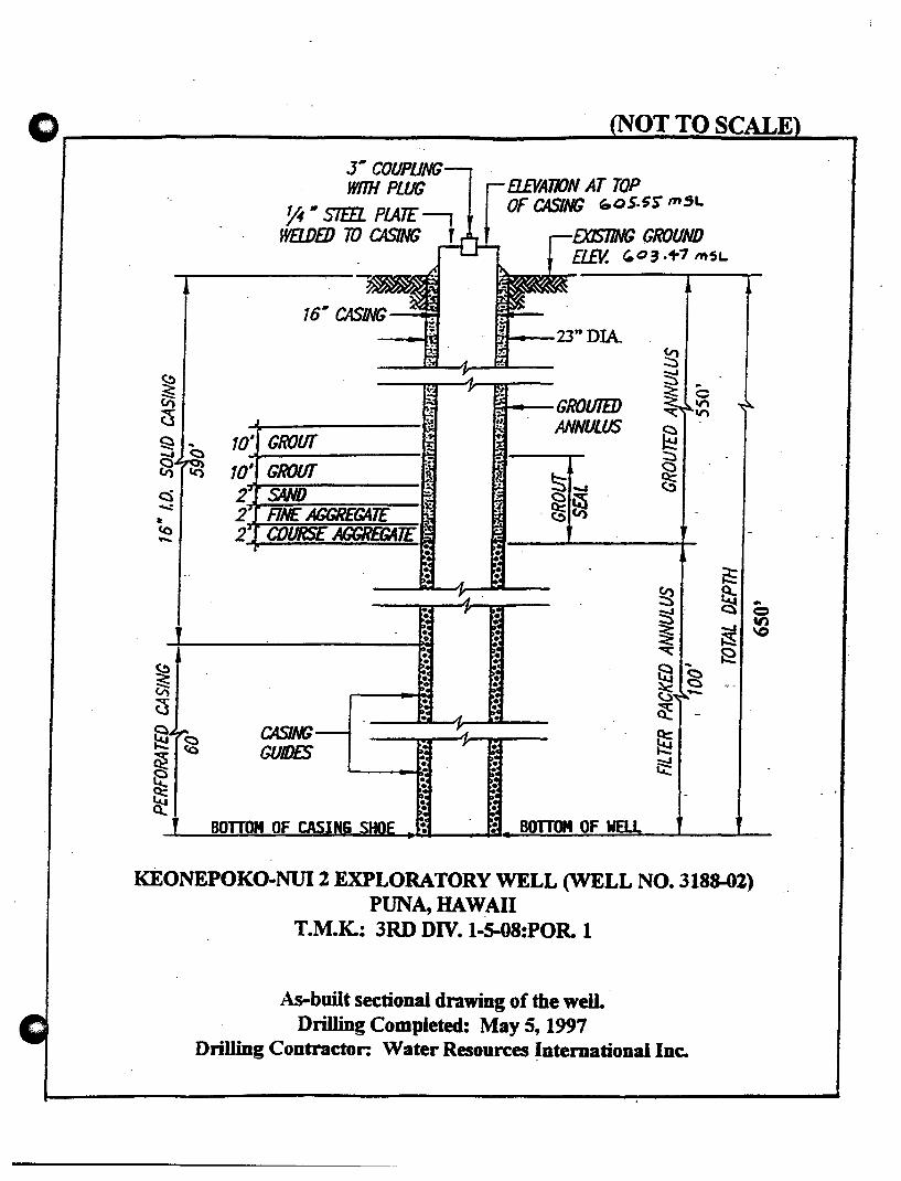
0 OTTO SCALE
J- COUPliNG WOH PWG B.£VATION AT TOP
~ • srm PlATE f OF CASING ~oS.5S mSL
WB..DED TO CASING f GROUND £L£V. "03· ... , "'SL
I 16- CASING
23"DIA ~
~ :s .. ;:<: c til GROUTED 11"\
CS ~ 11"\
ANNULUS § Q .. 10' GROUT ..... <::)
Sl-J ~
~ tc') 10' GROUT <:)
~ c::i 2 SAND <:)
~ .;,,: 2 FINE AGGREGATE .~ • <0 2 COURSE JCGR£GATE --
~ ~ e:. .. ~. Q <= ~ ~
ttl
<= \0 , ~ E ... ~ ~ g (i:i t5 -0 ~ ~ ~
CASING el t-;: GUIDES ..,;;;:
~ ~ ~ ~
BarroN OF BOTTOM OF WELL
KEONEPOKO-NUl2 EXPLORATORY WELL (WELL NO. 3188-(2) PUNA, HAWAII
T.M.K.: 3RD DIV. 1-S-08:POR. 1
As-built sectional drawing of the well. Drilling Completed: May 5, 1997
Drilling Contractor: Water Resources Intemationallnc.
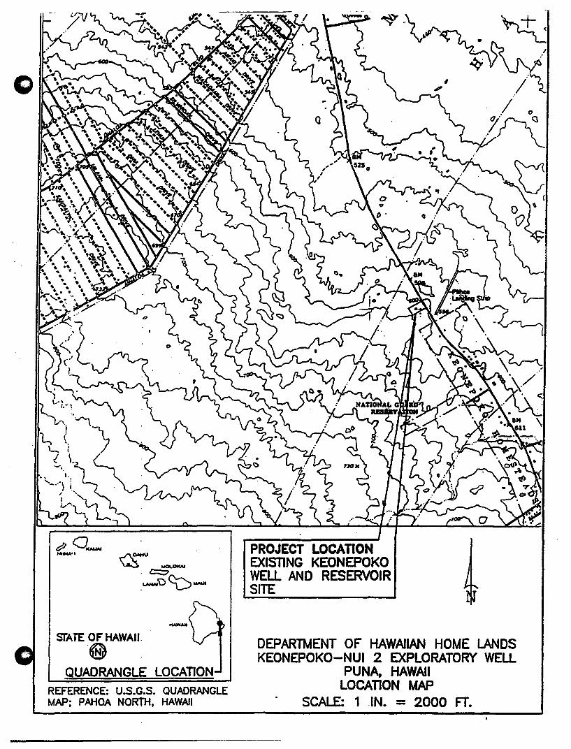
STATE OF HAWAII. .@ QUADRANGLE LOCATION
REFERENCE: U.S.G.S. QUADRANGLE MAP; PAHOA NORTH. HAWAII
PROJECT LOCATION EXISTING KEONEPOKO WELL AND RESERVOIR SITE
DEPARTMENT OF HAWAIIAN HOME lJ\NDS KEONEPOKO-NUI 2 EXPLORATORY WELL
PUNA, HAWAII LOCATION MAP
SCALE: 1 .IN. = 2000 FT.
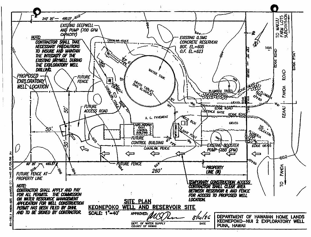
..
~I D ....
1U~20·
fJQ~ ~ FUTURE FENCE AT=- PROPERTY LINE C NOTE: i CtJN1RNJ1OR SH4U. APPLY AND PAY ii RJR AlL PERIII7S. THE ClMIISSDI li ON IH7ER REStJlJRC£ MWNBIEIIT ~ APPtX:A71ON FDR lEU txJNSIRIJCI10N z PERJIT HAS BEEN FlED Bf DIlL. &: AND TO BE SfGNE/) BY tXJN11W11lJR. m ci II)
~
Is:t I"/:,.. . '""\"",.~
~~.s ~_. ~\1a,t~
BE1IfEN RESSMlR a AND FENCE FOR II)CE$S lD IflOPOSED ItEU
SIT~ PLAN l/JC411ON. KEONEPOKO WELL AND RESERVOIR SITE
. ""~I 3b~ ~...1> :i~a ~\1..~
~I~IQ
2
i§ Q o
.Qj!
~I ~
'~ I<="· &.:
/
SCALE: 1-·40' N'PRrHm:/lj//'YJ), p'i,A, I DEPARTUENT OF HAWAIlAN HOME lANDS ;Vt<:{/~ U • KEONEPOKO-NUI 2 EXPLORATORY WEll
DEPT. Of' WATER SUPPLY COUNTY OF W.WAlI
DATE PUNA. HAWAII
o
APPENDIXB
RESULTS OF DRILLING AND TESTING
o
o
RESULTS OF DRILLING & TESTING
Keonepoko Nui Well 2 (3188-02) Puna, Hawaii
Prepared for
ENGINEERS SURVEYORS HAWAU, INC. Honolulu, Hawaii
Prepared by
WATER RESOURCE ASSOCIATES 1188 Bishop Street, Suite 1708
Honolulu, Hawaii 96813
Honolulu, Hawaii October 1997
o "
CONTENTS
Purpose and Description of ,Well . . . 0 0 0 0 • • 0 0 • • 0 0 0 • 0 • 0 • • • • • • : • 0 0 •
Geology- ............................................... . Hydrolo~ .............................................. .
1 1 1
Step-Dra.wdo'Wll Test ...... ". . . . . . . . . . . . . . . . . . . . . . . . . . . . . . . . . 2 Hydraulic Conductivity ................................. 2 Well Efficiency ........ . . . . . . . . . . . . . . . . . . . . . . . . . . . . . . 2 TraJlSmissivity ....................... . . . . . . . . . . . . . . . . 2
Constant Rate Test ................. 0 0 0 •• 0 0 0 0 •• '0 ••• 0 ••••• 0 0 0' 2
I Effect on Existing Well 0 0 0 0 0 0 • 0 0 0 0 0 0 0 0 0 0 0 0 • • • • • 0 0 • 0 • 0 0 • 0 3
Recovery Test ............... ~ . . .'. . . . . . . . . . . . . . . . . . . . . . . . . 3 Water Quality 0 0 0 • • 0 0 0 • 0 0 0 0 0 • 0 • 0 • • 0 0 • • 0 • 0 0 0 • 0 • 0 • 0 • • • • • • • • • 3
Chloride Content .. 0 • • • 0 0 • 0 • • 0 • • 0 • • • • 0 • • 0 0 • • • 0 • • • • • • • 0 3 Bacterial ........................................... 3 Organics and Me-ta.ls .•••••••.• .. . • • • • • • . . . • . • • • • • • • . • • . .
SUlDID.8lY' • • • • • • • • • • • • • • • • • • • • • • • • • • . • • • • ". • • • • • • • . • • • • • • • Permanent Pump Recommendation ...........:...................
Appendix A. Calculation of Hydraulic Conductivity, K B. Pumping Test Record Co Aecos Report of Microbiological Results D. Brookside Analysis Report E. EoL. Pacific Laboratory Report
Fiaure
1 2
.3 4 5 6 7 8
FIGURES
Regional Water Development Plan As-Built Section of Well Hydrolo~ Map Step Dra.wdown Curve Pumping Rate vs Dra.wdo'Wll Curve S/Q Curve Time-Drawdown Curve Time-Recovery Curve
ii
3 4 4

c
o
RESULTS OF DRILLING AND TESTING Keonepoko Nui Well 2 (3188-02), Puna, Hawaii
Purpose and Description of Well
In 1996, the Department of Hawaiian Home Lands (DIDa) required a new potable water source for its Makuu Farm and Agricultural Lots Subdivision located northwest of Pahoa town in the Puna District of Hawaii. Consequently, construction of an exploratory well was started in February 1997 in the County Department of Water Supply's Keonepoko Reservoir and Tank Site (TMK: 1-5-08:Por. I) at an elevation of 603.5 feet, msl. The new well, called Keonepoko Nui Well 2, was to provide potable water for 99 lots in the low service area of the subdivision and an additional 30 lots planned on an adjacent FAA leased lot (see Figure 1). Based upon a unit demand of 2,400 gallons per day (gpd) per lot, the projected DHHL water demand for the well was estimated at 309,600 gpd.
Keonepoko Nui Well 2 was completed in May 1997 to a total depth of 650 feet (-46.5 ft., msl). The well is cased with 16-inch ID steel casing to its total depth, with the bottom 60 feet consisting of full-flo, ~" opening, louvered screen (see Figure 2).
Geology
Keonepoko Nui Well 2 started in prehistoric flank flow basalts of the Puna Volcanics and, presumably, was completed in the same basalts. These basalts are· geologically young (30 to 10,000 years at the surface), relatively unweathered, highly permeable and yield water readily to wells. The basalts are dike-free in the vicinity of the well.
Hydrology
The well lies within the Pahoa Aquifer System, which is one of four aquifer systems included in the 564 square-mile Kilauea Hydrologic Sector. The Pahoa aquifer extends from Kilauea Volcano eastward to the coast, and comprises an area of 222 square miles. The aquifer system is water-rich and has an estimated sustainable yield of 435 mgd Rainfall in the vicinity of the well averages 150 inches a year (see Figure 3). Pumping tests on Keonepoko Nui Well 2 have confmned the generally known highly penneable characteristic of the Puna basalt flows and the existence of a thick, pristine basal aquifer having a head of 16.7 feet and chloride content of only 6 mgll.
.~
o Step-DrawdoWD Test
o
On May 28, 1997, a step drawdown test was performed on the well at pumping rates ranging from 765 gpm to 1410 gpm, with corresponding initial drawdowns ranging from approximately 3.3 ft. to 11.3 ft. (see Figure 4). The Pumping Rate vs Drawdown Curve shown in Figure 5 shows initial drawdowns which can be expected in the well for different rates of pumping.
Hydrtlulic Conductivity. The hydraulic conductivity of the aquifer is approximately 1,460 ftJday based on the step drawdown data in Figure 5 and 6 (see calculation in the appendix).
WeB EffICiency. The efficiency of the well is expressed as the quotient of aquifer drawdown (s..) divided by the total drawdown (s.a...) multiplied by 100. The efficiency of Keonepoko Nui Well 2 is approximately 7.7% (100 x 0.36 ft. + 4.7 ~).
TrllllS1llissivity. The transmissivity of the aquifer, as derived from the relationship, T = Kb, is 999,660 ft.2/day (T = 1460 ftJday x 16.7 ft. x 41 ft.).
Constant Rate Test
A S-day constant rate pumping test was performed on Keonepoko Nui Well 2 from May 29 to June 3, ·1997. During the test, drawdown was.measured by airline pressure readings and directly by a scaled sounding probe. The probe data, however, . was considered more accurate and used in all analyses. Figure 7 shows a semi-log timedrawdown plot of the constant rate test data (see Pumping Test Record in appendix). The transmissivity, T, of an aquifer normally can be calculated from the earliest part of a time-drawdown curve, which for the highly permeable aquifer of Keonepoko Nui Well 2, would probably be the first 100 minutes of pumping. Transmissivity values calculated from later parts of the curve may be affected by hydraulic discontinuities in the aquifer and, consequently, may represent less than true aquifer transmissivity. A transmissivity value of 2.9 x 10' gpdIft. was derived from a graphical analysis of the first 100 minutes of the curve in Figure 7. T is calculated from the relationship, T = 2~sx 0 , where Q is the pumping rate and AS is the drawdown per log cycle.
An offset in the observed drawdown occurs between approximate time, t = 900 minutes to t = 2400 minutes (see Figure 7). However, the two shifts in the time drawdown curve occurred between 12:30 am and 1:30 am, raising the suspicion that human error, rather natural occurrence, was likely involved. As can be seen in Figure 7, it is difficult to determine precisely any drawdown trends, but a hydraulic discontinuity in the aquifer probably occurred between t = 900 and t = 1000 minutes. Also, drawdown in the well appears to have reached an equilibrium of approximately 5.7 ft. during the fIfth day of pumping at the rate of 1,000 gpm.
2
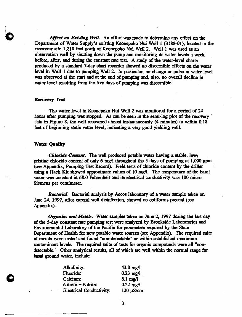
1
(>
o
.'
Effect on Existing WeN. An effort was made to determine any effect on the Department of Water Supply's existing Keonepoko Nui Well 1 (3188-01), located in the reservoir site 1,210 feet north of Keonepoko Nui Well 2. Well 1 was used as an observation well by shutting down the pump and monitoring its water levels a week before, after, and during the constant rate test. A study of the water-level charts produced by a standard 7-day chart recorder showed no discernible effects on the water level in Well 1 due to pumping Well 2. In particular, no change or pulse in water level was observed at the start and at th~ end of pumping and, also, no overall decline in water level resulting from the five days of pumping was discernible.
Recovery Test
I The water level in Keonepoko Nui Well 2 was monitored for a period of 24 hours after pumping was stopped. As can be seen in the semi-log plot of the recovery . data in Figure 8, the well recovered almost instantaneously (4 minutes) to within 0.18 feet of beginning static water level, indicating a very good yielding well.
Water Quatity
Chloride Content. The well produced potable water having a stable, Jew;. pristine chloride content of only 6 mg/l throughout the 5 days of pumping at 1,000 gpm (see Appendix, Pumping Test Record). Field tests of chloride content by the driller using a Hach Kit showed approximate values of 10 mg/l. The temperature of the basal water was constant at 68.0 Fahrenheit and its electrical conductivity was 100 micro Siemens per centimeter.
Bacterilll. Bacterial analysis by Aecos laboratory of a water sample taken on June 24, 1997, after careful well disinfection, showed no coliforms present (see Appendix).
Organics tuld MetIIIs. Water samples taken on June 2, 1997 during the last day of the S-day constant rate pumping test were analyzed by Brookside Laboratories and Environmental Laboratory of the Pacific for parameters required by the State Department of Health for new potable water sources (see Appendix). The required suite of metals were tested and found "non-detectable" or within established maximum cOntaminant levels. The required suite of tests for organic compounds were all "nondetectable." Other analytical results, all of which are well within the normal range for basal ground water, include:
Alkalinity: Fluoride: Calcium: Nitrate + Nitrite: Electrical Conductivity:
43.0 mgll 0.23 mgll . 6.1 mgll 0.22 mgll 120 J.1S1cm
3

"
o Summary
o
Keonepoko Nui Well 2 has been successfully drilled and tested as a potable source of water supply capable of producing basal water of pristine quality at a rate of 1,000 to 1,400 gpm. The well extends only 46.5 feet below sea level, affording optimum development of the basal lens. The well has the following characteristics:
Ground Elevation: Casing Diameter: Solid Casing Depth: Screen Casing Depth: Total Well Depth: Head: Chlorides: Test Rate: Drawdown @ 1,000 gpm:
Permanent Pump Reeommendation
603.5 ft., IDSI 16-inch I.D. 590 ft. (+13.5 ft., IDSI) 650 ft. 650 ft. (-46.5 ft., IDSJ) 16.7 ft. 6mgll 1,000 gpm 5.7 ft.
The pumping test results indicate that Kconepoko Nui Well 2 is capable of yielding 1,000 to 1,400 gpm. However, it is recommended, at this time, that the capacity of the permanent pump to be installed in the well fall within the nmge of 700 to 1,000 gpm.
4
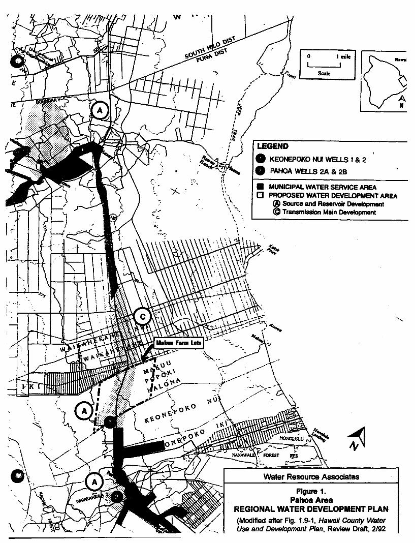
! w ..
i. I
\
o I mile
I I Sc:alc
LEGEND
• KEONEPOKO NJI WElLS 1 & 2
• PAHOA WElLS 2A & 2B
\\ • MUNICIPAL WATER SERVICE AREA " , \" B PROPOSED WATER DevELOPMENT AREA
® Source and Reservoir Development \\ \ .~
\ .... \ .....
", . \ .
@ Transmission Main Development
Figure 1. Pahoa Area
REGIONAL WATER DEVELOPMENT PLAN (Modified after Fig. 1.9-1, Hawaii County Water Use and Development Plan, Review Draft, 2192
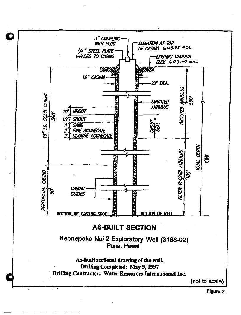
CASING GUIDES
• •
El£VATION AT TOP OF CASING ,-oS.5~ Ift.5L
"--J~IIIYU GROUND B..EV. ~o 3 .+7 ~SL
DIA.
BOTTOM OF WELL
AS-BUILT SECTION
Keonepoko Nui 2 Exploratory Well (3188-02) Puna, Hawaii
As-built sectional dnwiDg of the welL Drilling Completed: May 5, 1m
. DrilliDg Contractor: Water Resources International Inc.
(not to scale)
Figure 2
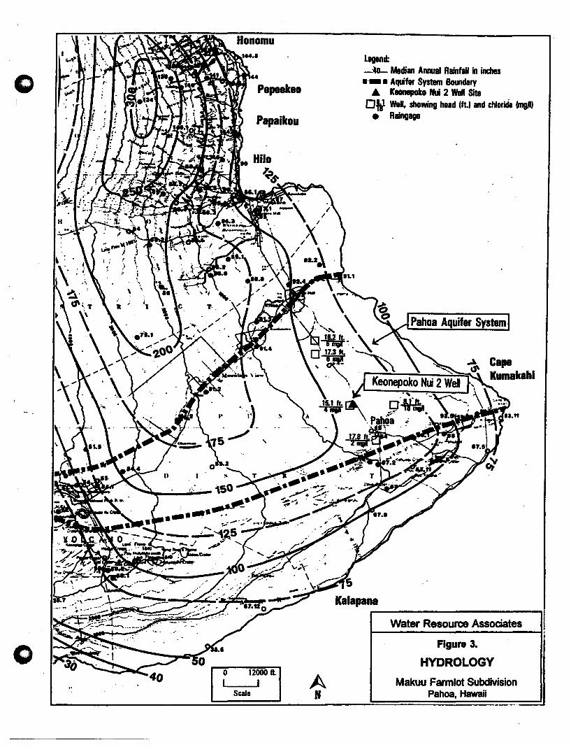
o Papaikou
o o 12000 ft. I I A
Scale N
Legend: -AD- Median Amual Rainfall in inches .- •. Aquifer System Boundary
A Kaonepoko Nui 2 Well Site Off Well. showing head lilt and chloride ImgIIt
• Raingaga
Pahoa Aquifer System
Water Resource Associates
Figure 3.
HYDROLOGY
Makuu Farmlot Subdivision Pahoa, Hawaii

c
o
STEP DRAWDOWN CURVE Keonepoko Nui 2 Well (3188-02), Hawaii
Date of Test: May 28, 1997 .
Drawdown, in ft. O~------~--------~------~--------~-------,
I! I
~2~ __ ~~7_6_~~1 _gp_m ______ ~,I!I.I--------~---(-p-rO-b-e~ID-a-ta-)-----1 I .1930 gpm
"j i . -4 +-. ---
i
I 1140 gpml
- 6 ~-- .---+---
-8~-----~--------i--- ---+----~--+-----~
I 1 0 I--------t--------+---------!l-------I----i------
- I I 1410 gpm
I -12 I--------+---------i------r----"""d-+-------
i
-14L--------L--------~------~--------~------~
o 50 100 150 200
Time Since Pumping Started, in minutes
Wet.r A •• oure. A •• oelet •• 0738DC1
-Drawdown
250
Figure 4

" ca' e i Con
PUMPING RATE VS DRAWDOWN CURVE Keonepoko Nui 2 (3188-02)~ Hawaii
Date of Test:. May 28, 1997
Drawdown in feet
---1- I ---I+~ --------I-------t-+-.r il1-10 I ! \ I I !
I I. I I I 1~----~--~~--~~~~----~~~~~~~~~
o
100 1000 10000
W.,.r R ..... r •• A •••• '., •• """RDD'.
Pumping Rate in gpm
-Drawdown
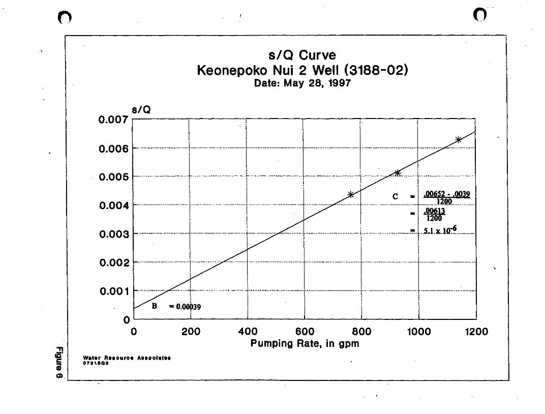
o
"T1 cC' e iii
s/Q
s/Q Curve Keonepoko Nui 2 Well (3188-02)
Date: May 28, ·1997
o
0.007--------~------~------~------~------~------~
0.006
I . o .00 5 ... ·· ... -················ ... -··-·· ... _-··-·-·_·1 -.............................. - .......... -....................................... -....... ----..... - ......... ---........ - ........... -.......... ·· ... -· ......... ·-·-···-· ... ·-·-... -·-········ ... ······-·t··-·-·- .. , ........ -. - .... -:-.-..... 1-............ - ........................ - ......... --•.. - ......... - ......... .
I C _ ,OO6S2 - ,0039 o . 0 0 4 ...... -.............. _ .................... -.... -..... -................. -...... --.............................. -...... -.............. , ......................... -...... -................ -······-t ... ···· ... ·· ... ··· .................... ............................ ... . ....... ......... ..-.................. -.... -.. _ ............ _._ .... _ .. _ ... ..1 20.0 ................... -. I " - .00613 ! I~
0.003 ................... _ .... ___ ............... _ ........ ___ .................... _ ... _ ........................... _ ...... _ ............. __ ... __ ~. ,.LLl~ .. _ ......... __ _
0.002
0.001
O~------~------~------~------~------~~----~
o 200
Wat.r ft •• ouro. A .. oolat .. 07a,aQI
400 600 800 Pumping Rate, in gpm
1000 1200
"
Q.~------------------------------------------------------------~

Feet
TIME-DRAWDOWN CURVE Keonepoko .Nui 2 Well (3188-02), Hawaii
Date of Test: May 29-June 3, 1997
Head • 16.7 ft. Pumping Rate: 1000 gpm
/' Feet 0~--~~-r~~--~~-r~~--'-~~~~--~~-r~1I0
GrJ E"I" .oHI'H I II I I I I II I II I I ! II I -1 ___ TDI" Ttnl- t--iiif-r 1---[---1-rill 1-/- t-:-lti-t
1l ~ -1
-2 - -..... " . ···+-t ,··t + ·f· r'--'" .... -! .. ·····t---·j-··-rt··\- i-" ...... -- .... -. -.-.' j-- '" . t-·tJr I - -- - - til + r ,II ~ -2
! I i I ; 'II ! I 'I I I II! I :1: II II: i i ! I Ii!' ! i I j I 1 I I I ! :
-3 - - i!--r- -Ii - -- -- i --1,- 1,--r- ,- -- -- --T --- -'- ---- --+-'11111+: -3
I I 'I . ' I, I I
I I, I _ .... -. -. -- -1,-- .- "'f,'" '-'j' ---1---t ... - .} r-'--' .----. - .-. --. ..1. ____ . ...... -. i_.1 . -.. -" . j... 1- 'f,'"'+ Ii" j I t - -4 -4 _.
.- -' . I i I ! Ii \
- 6 - ---~--- - ---,'1---+-+-+-----1-1- -----'- -~~ _lrl~I_IJli j ~ -6
I 1/ , ii' i l' II .-- I~ I ~~ .. , Ji I I i I I 1 I--6+---+I-+,-rrH~In---+I-+I-rrH,+H---+I-+,-rHH+H-I--+,-+,~,~H4+L_6
1
Water R •• ouro. Anoolat •• 07lTDCa
10 100 1000 10000 . Time since pumping started, in minutes
I - Drawdown lit) ,
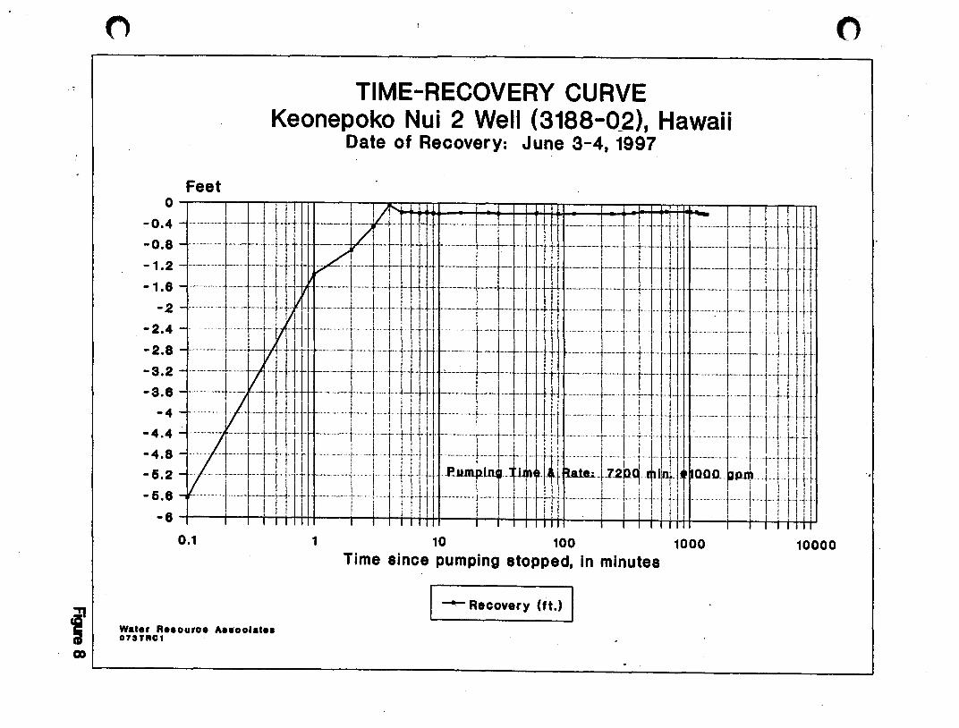
Feet
TIME-RECOVERY CURVE Keonepoko Nui 2 Well (3188-0_2), Hawaii
Date of Recovery: June 3-4, 1997
= ::: = ., -, .1:J ~iW=~-k + :'::,~ -:-~~: : -t ·~~·l-'\ . :'J1,-_:. ~~ .1 jl W
= :::. I---r-tb-Lrrt ------., r--T -"'. --, -l'· fl-pl -2
-2.4
-2.8 - - ....... f·_······+--+ ., tl-- ,,-- t"""'r '-r lll'- ._ .... "" .-.-- .". ." .-." ,,_. "" ... "····""1"· 1'1' .. " ... "."',' ["""'1'- 1--"" j ['-rt
= ::: = ,'~-~ =+t" " ~: ~t~ll! ::)\ ~'j~~,: '-t:t )-: :' ,:\ :~II :'-~-,l:1 f 'J 11 rj: -4 -, ,,, .. I """-"""1" d'"r ".,,' r .. ,!, 1 tool "It '"." ,j"" 1"'" "' '-l- t,l ."" . t· t ! L I "." ".' 1'""1 I j' d
I ! 1 ! I I I • II! i ! I I I ' I I! I. I r : i'
-4.4 - """-"""'1" 't-' '['-j"+t' "I "" "."" t, it ""j-"t, "1 j It ._"'"." j' ,," "r "'j" t"lll t I'" "r ! i 11.1 t', 'Jt' t· "j" tIl rr t'l
=::: =trtrrI r,i ': ill Ij ~..JIll,;nH~~I~' ~at .. h2~H4I'~' o~-~ tp~, rill [! I I J I! ~ Ii! : : II! i ',I ! I I . 1 i I !: I r i j I I I ! :
-5.6 - - ". "I· .. "I'''""" "rl j " ... "" i ' '; j t" tIl' "'''''''' I "" I· f 1" rHo '" .l... L ! j I lJ t' ". I . I" " I r d !. iii I Ii! i : Ii., I I I I I I! I I : ! I III I!. I Iii
-6 I I I I I II I I I I I III I I I 1 I II I I I I I III I I I I I III
0.1
Wat.r R •• ouro. A •• oolat •• 07aTRC1
1 10 100 1000 10000 Time since pumping stopped, in minutes
I --- Recovery (It.) I

! .'
C
APPENDIX
o . .
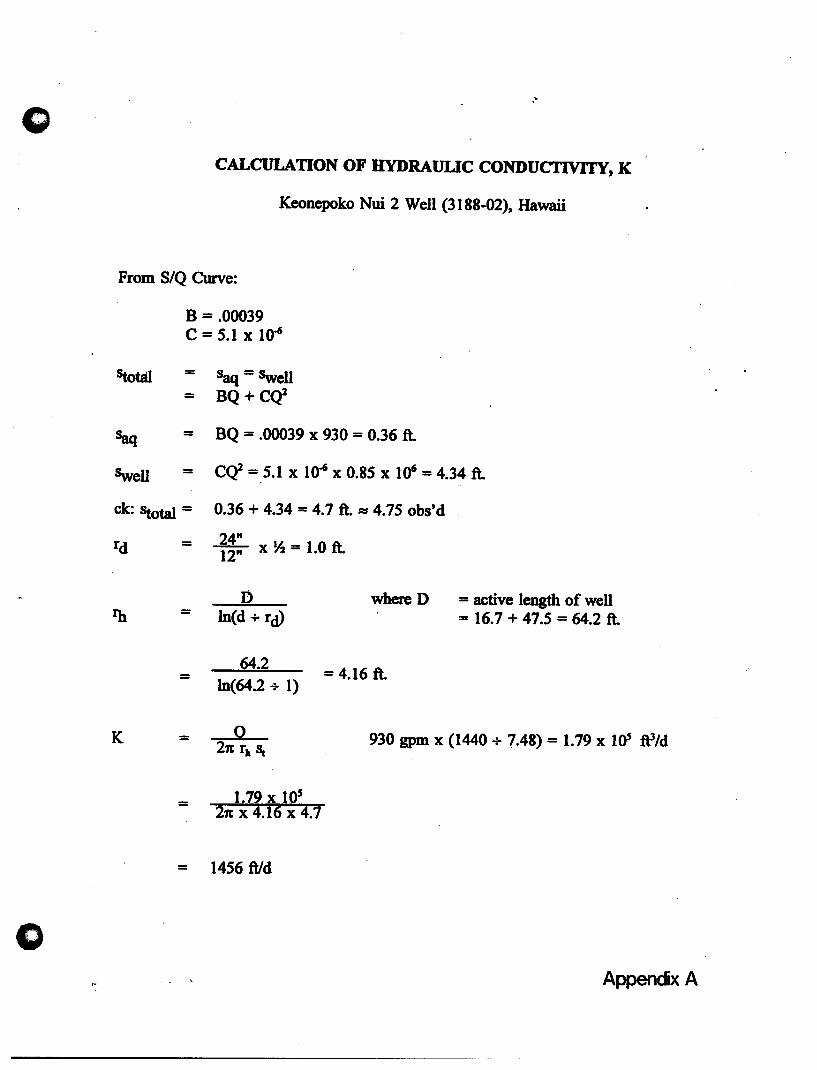
o
"
CALCULATION OF HYDRAULIC CONDUCTIVITY, K
Keonepoko Nui 2 Well (3188-02), Hawaii
From S/Q Curve:
B = .00039 C = 5.1 X 10⁻⁶
statal = Saq = Swell - BQ+C<l
Saq = BQ = .00039 x 930 = 0.36 ft.
Swell = C<l = 5.1 x 10-6 x 0.85 X 10' = 4.34 ft.
ck: stotal = 0.36 + 4.34 = 4.7 ft. AS 4.75 obs'd
rd = i~: x ~ = 1.0 ft.
D where 0 In(d + rd>
= 64.2
= 4.16 ft. In(64.2 + 1)
= active length of well = 16.7 + 47.5 = 64.2 ft.
K = 930 gpm x (1440 + 7.48) = 1.79 x lOS ft3/d
=
= 1456 ftld
AppendxA
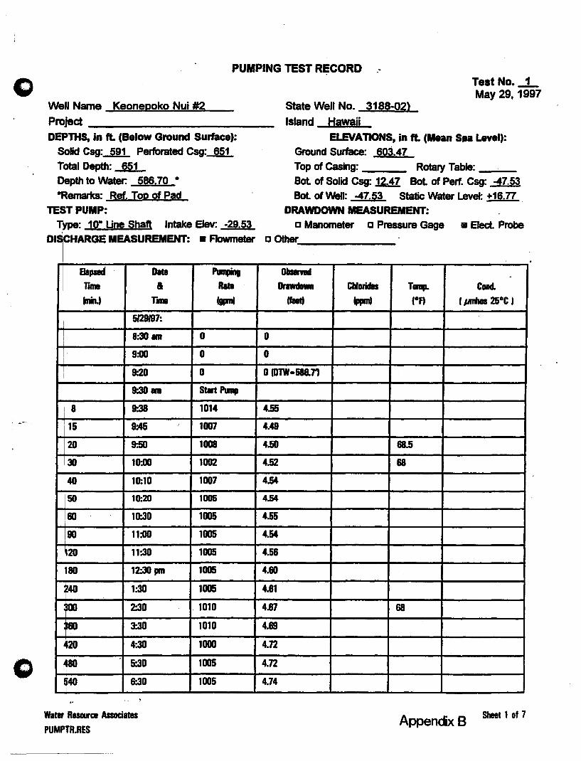
o
o
PUMPING TEST RECORD ."
Well Name Keonepoko Nui #2 State Well No. 3188-02)
Test No • ..,:L May 29,1997
Projed ______________________ __ Island Hawaii
DEPTHS, in It. (Below Ground Surface):
Solid Csg:-Rn.. Perforated Csg: 851 Total Depth: 651 Depth to Water: 586,70·
*Remarks: Ref, Top of Pad
TEST PUMP: Type: 10" Une Shaft Intake Elev: -29,53
D IS CHARGE MEASUREMENT:
aa,., 0111 rlBll a (nin.t r ...
i 5129197: I
! 8:30 l1li
I 9:00
1 9-.20 \
,
9-.30 l1li i
8 9:38
15 9:45
20 9:50
30 10:00
40 10:10
50 10:20
160 10-.30
90 11:00
20 11:30
80 12:30 pm
40 1:30 ,.., 2:30
so 3:30
.20 4:30
Jao 5:30
!4O &.30
Watar Resource Associates
PUMPTR.RES
.-
8 Flowmeter
....... R.ta
fgpml
0
0
0
Start PIInp
1014
1007
1008
1002
1007
1005
1005
1005
1005
1005
1005
. 1010
1010
1000
1005
1005
ELEVAnONS, in ft. (Mean S •• Level): Ground Surface: 603,47 Top of casing: Rotary Table: ____ _
Bot of Solid Csg: 12.47 Bot of Perf. Csg: -47.53
Bot of Well: -47,53 Static Water Level: +16,n DRAWDOWN MEASUREMENT:
o Manometer 0 Pressure Gage 8 Elect. Probe o other
0 __ .
IJrawdDMt Chlorides T...,. Cond.
IfaetJ (ppmJ (of) (poNs 25°C'
0
0
o (DTW-586.n
4.55
4.49
4.50 88.5
4.52 68
4.54
4,54
4.55
4.54
4.56
4.60
4.81
4.67 68
4.69
4.12
4.72
4.74
Appencix B Sheet 1 of 7

o
Pumping Tast Record (Cont'd)
Well Nama: KlOnepoko Nui 12
Elapsed Date TI11'II &
(min.I THne
5129197:
600 7:30 pm
660 8:30
720 9:30
780 10:30
840 11:30
5/30197:
900 12:30 am
960 1:30
1020 2:30
1080 3:30
1140 4:30
1200 5:30
1260 6:30
1320 7:30 :
13.80 8:30
1440 9:30
1500 10:30
1560 11:30
1620 12:30 pm
1680 1:30
1740 2:30
1800 3:30
1860 4:30
1920 5'.30
1980 6:30 . 2040 7:30
2100 8:30
2160 9:30
Water Resource Associates
.~
State Well No. 3188=02 Test No.~
Pumping Db ..... Rate Drawdown Chlorides Tamp. Cond. (- (feet) (ppm) (OA (mmhos 25°CI
1005 4.77
1000 4.79 6 68 100
1005 4.78
1005 4.n 1000 4.n
980 4.80
1000 5.24
1005 5.31 68
1000 5.31
1005 5.34
1005 5.37
1005 5.44
1005 5.47
1005 5.49 6 68 100
1005 5.49
1015 5.47
1015 5.46
1010 5.47
1010 5.46
1015 5.46 68
1015 5.44
1010 5.40
1010 5.40
1010 5.43
1005 5.42
1010 5.44 6 68 100
1010 5.45
Sheet 2 of 7
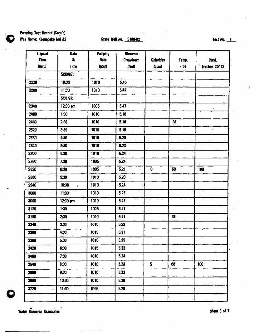
o
PUII1Jing Test Record (CDf!I'd) Well Nama: KlDnapoko Nui 12
Elapsed Date
TIII18 &
(nin.) Tn
5130197:
2220 10:30
2280 11:30
5/31197:
2340 12:30 am
2400 1:30
2460 2:30
2520 3:30
2580 4:30
2640 5:30
2700 6:30
2760 7:30
2820 8:30
2880 9:30
2940 10:30
3000 11:30
3060 12:30 pm
3120 1:30
3180 2:30
3240 3:30
3300 4:30
3360 5:30
3420 6:30
3480 7:30
3540 8:30
3600 9:30
3660 10:30
3720 11:30
,. Water Resource Associates
.-
.'
State Well No. 3188-02 Test No._l_
PlInping Obsenad
Rate Drawdown Chlorides Tamp. Condo (gpm) (feet) (ppm) (DA . (mmhos 25DC)
1010 5.45
1010 5.47
1005 5A7
1010 5.18
1010 5.18 68
1010 5.19
1010 5.20
1010 5.23
. 1010 5.24
1005 5.24
1005 5.21 6 68 100
1010 5.23
1010 5.24
1010 5.25
1010 5.23
1005 5.21
1010 5.21 68
1015 5.22
1015 5.21
1015 5.23
1015 5.22
1010 5.24
1010 5.23 5 68 100
1010 5.23
1010 5.30
1005 5.29
Sheet 3 of 7
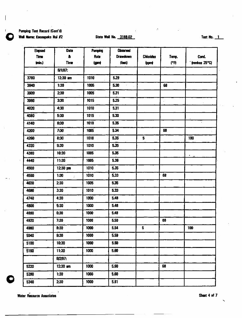
Pun1Jing T~ Record (Cont'd)
Wall Nama: Kaonapoko Nui 12
Elapsed Date
TIme &
(ninJ TIII18
611197:
3780 12:30 am
3840 1:30
3900 2:30
3960 3:30
4020 4:30
4080 5:30
4140 6:30
4200 7:30
4260 8:30
4320 9:30
4380 10:30
444D 11:30
45DD 12:30 pm
4560 1:30
4620 2:30
4680 3:30
4740 4:30
4800 5:30
4860 6:30
4920 7:30
4980 8:30
5040 9-.30
5100 10:30
5160 11:30
612197:
5220 12:30 am
5280 1:30
5340 2:30
'" Water Resource Associates
,
0'
State Wall No. 3188-02 Test No._1_
PIIr1Iing ObS8l'Ylld
Rate Drawdown Chlorides T ...... Cond. (gprnt (feet) (ppm) (DA . (mmhos 25DC)
1010 5.29
1005 5.3D 68
1005 5.31
1015 5.25
1010 5.31
1015 5.30
1010 5.35
1005 5.34 68
1010 5.35 5 100
1010 5.35
1005 5.35 . 1005 5.36
1010 5.35
1010 5.33 68
1005 5.35
1010 5.33
1000 5.48
1000 5.48
1000 5.48
1000 5.50 68
1000 5.54 5 100
1000 5.59
1000 5.60
1000 5.60
1000 5.60 68
1000 5.60
1000 5.61
Sheet 4 of 7

Purqing Test Record (Cont'd)
Well Name: Keonapolco Nui 12
Elapsed Date
TIne &
(nin.) Tn
612/97:
5400 3:30
5460 4:30
5520 5:30
5580 6:30
5640 7:30
5700 8:30
5760 9:30
5820 10-.30
5880 11:30
5940 12:30 pm
6000 1:30
6060 2:30
6120 3:30
6180 4:30 ,
6240 5:30
6300 6:30
6360 7:30
6420 8:30
6480 9:30
6540 10:30
6600 11:30
6/3197:
6660 12:30 am
6720 1:30
6780 2:30
6840 3:30
6900 4:30
6960 5:30
Water RBSOuree Associates
State Well No. 3188.1J2 Tast No.-1-
".,.g Obsarnd
Rate Orawdown Chlorides Tamp. Conet. (. (flat)
(. (OA • (nJnhos 25°C)
1000 5.62
1005 5.85
1005 5.70
1005 5.69 .68
1000 5.65
1005 5.63 5 100
1005 5.63
1005 5.64
1000 5.69
1000 5.68" 68
1000 5.70 -
1000 5.68
1000 5.68
1005 5.70
1005 5.69
1005 5.70
1005 5.71 68
1010 5.75 5 150
1010 5.80
1010 5.78
1015 5.79
1005 5.63 68
1005 5.64
1010 5.68
1010 5.69
1010 5.68
1010 5.68
Sheet 5 of 7

o
o
Punfing Tast Record ICont'd, waU Nama: Kaonepoko Nui 12
Elapsed Data
Tnna &
lnin.' TIIIII
813197:
7020 6:30 am
7080 7:30
7140 8:30
7200 9:30
STOP PUMP-
1 9:31
2 9:32
3 9:33
4 9:34
5 9:35
6 9:36
7 9-.37
8 9:38
9 9:39 ..
10 9:40
15 9:45
20 9:50
25 9:55
30 10:00
60 10:30
90 11:00
120 11:30
150 12:00 PM
180 12:30
240 1:30
300 2:30
360 3:30
420 4:30
Water Resource Associates
"
State Well No. 3188-02 Tast No • ..l-
PlIIIPing Obsamd Rata Orawdown Chlorides . Tamp. Condo
I!PII' Ifaat) Ippm) lOA . fnmhos 25°C'
1005 5.57 68
1005 5.61
1010 5.60
1005 5.64
RECOVERY
1.36
0.9
OAS
0.04
0.18
0.17 -
0.19
0.18
0.19
0.2
0.18
0.18
0.18
0.19
0' 0.18
0.19
0.18
0.18
0.18
0.18
0.17
0.16
0.14 0
Shill 6 of 7
"

Ptlnping Test Record (Cont'd,
Well Nama: Keonepoko Nui 12
Elapsed Date
rll1ll &
(nin.' r ... 813/97:
480 5:30 PM
540 6:30
600 7:30
660 8:30
720 9-.30
780 10:30
840 11:30
614197:
900 12:30 am
960 1:30
1020 2:30
1080 3:30
1140 4:30
1200 5:30 :
1260 &-.30
1320 7:30
1380 8:30
Water Resource Associates
State Wei No. -3188.(J2 Test No. _1 _
~ Observed Rata orawdown Chlorides T ...... Cond.
(p' (feet) (ppm) (Df) (nJmos 25DC,
0.14
0.14
0.14
0.13 .-
0.13
0.13
0.13
0.13
0.13 . 0.14 .
0.14
0.14
0.15
0.1&
0.17
0.17
-
Sheet 7 of 7
"
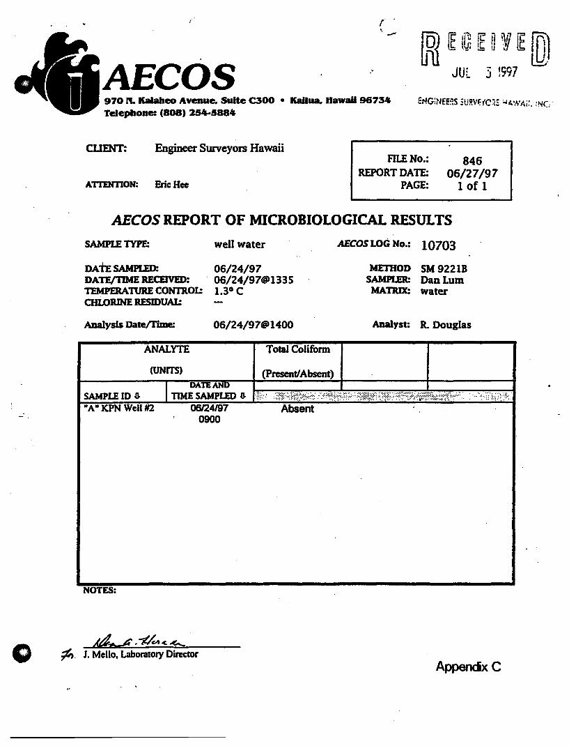
r - 1Ri ~ fa [ ~ Wi ~ [D) JUL 3 ~997 AECOS "
970 rI. Kalabeo Avenue. SuIte C300 • KaIlua. Hawaii 96734 Telephone: (808) 254-5884
CUENT: Engineer Surveyors Hawaii
ATI'ENTION: Eric Hoe
FILENo.: REPORT DATE:
PAGE:
846 06/27/97
1 of 1
AECOS REPORT OF MICROBIOLOGICAL RESULTS
SAMPLE TYPE: well water AECOS LOG No.: 10703
DAtE SAMPLED: 06/24/97 METHOD SM 9221B DATE/11ME RECEIVED: .06/24/97@1335 SAMPLER: DanLum TEMPERA1lJRE CONTROl: 1.3° C MATRIX: water OILORINE RESIDUAl:
ADalysls Date/Time: 06/24/97@1400 Analyst: R. Douglas
ANALYTE Total Coliform
(UNITS) (present/Absent)
SAMPLE 10 3 "A" KPN Well 1#2 06124197 Absent
0900
NOTES:
~, 1. Mello, Laboratory Director Appendx C

BROOKSIDE LABORATORIES, INC. ENVIRONMENTAL & INDUSTRIAl DIVISION
P.o. BOX 456 308 S. MAIN STREET . NEW KNOXVILLE. OH 45871
(419) 753-2448
aNALYSIS ImPORT
We are pleased to submit the following AIIalysJs Report. Please review the data and feel &ee to call us if yoU have questions or need. additional tests and/or tec:huical assistance.
This report shall not be reproduced except in foB and with the written approval &om Brookside Laboratories, Inc.
GENERAL INFORMATION t
Account No : 61690 .Report Submitted To: Verle Heyer
CUent Name: Brewer Environmental Ind. Report No : DE73637
Project Name: Lab Job #E7060206 Report Date: 06117197
Site NamelLocation :
Sample Collected Dr. H. 1;'onaka
Comments: voe·s. SOC's, and metals were analyzed by Environmental Health Laboratories of South Bend. Indiana; Fluoride was analyzed by BU.
ANALYI'ICA,L RESULTS
Analytical results are presented on page 2 lhr.ougb. page S of this report. -
AU11IORI7.EO SIGNATURES
~L ~ ( !lUi ¥1f. ~
Zhilun Xue, Ph.D. Lam V. Ho, Ph.D .• REP,
Senior Chemist Director. EID
Appendx 0
o
BROOKSIDE LABORATORIES, INC. ENVIRONMENTAL & INDUSTRIAL DIVISION
P.o. BOX 456 308 S. MAIN STREET NEW KNOXVILLE, OH 45871
(419) 753·2448
~NALYSIS imPORT
We are pleased to submit the following Analysis Report. Please review the data and feel free to call us if you have questions or need additional tests and/or technical assistance.
This report shall not be reproduced except in full and with the written approval &om Brookside Laboratories, Inc.
GENERAL INFORMATION
Account No : 61690 Report Submitted To: Verle Heyer
Client Name: Brewer Environmental Ind. Report No : DE73637
Project Name: Lab Job #E7060206 Report Date: 06120197
Site NamelLocation :
Sample Collected By: H. Tanaka
Comments: Resubmitting page 4 with Dioxin results. Dioxin results were performed by Core Laboratories in Indianapolis, Indiana.
ANALYI'ICAL RESULTS
Analytical rt:SullS iUe presented on page 2 through page 5 of this report.
Peter A. Coni~s
QAlQC Officer
AUTHORIZED SIGNATURES
Lam V. Ho, Ph.D., REP,
Director. EID

() FILE NO: 61690
CLIENT NAME : Brewer Environmental Ind.
PROJECT NAME: Lab Job tlE7060206
Brookside Laboratories, Inc.
PAGE NO : 20f5
REPORT NUMBER: DE73637
REVIEWER INITIALS: ( ,it",
TEST NAME : ** METALS **
SAMPLE MA TR1X: WATER
SAMPLEID: E7060206
SAMPLE DESCRIPTION: KEONEPOKEO NUl 2 WELL
LAB NUMBER: DE73637
PREPMETHOD-:
DATE SAMPLED: 06/02197
DATE RECEIVED: 06/05/97
DATE REQUESTED ADDITIONAL TEST:
DATE ANALYZED: 06/17197
ANALYST: NT
CODE ANALYTE ANALYTICAL RESULT LIMIT OF DETECTION
METHOD ( ug/I ) ( ug/I )
IB021 ANTIMONY EPA 200.8 NlD 0.2
IB032 ARSENIC EPA 200.8 N/D 0.5
IB040 BARIUM EPA 200.8 1.9 0.1
IB051 BERYLLIUM EPA 200.8 NlD 0.1
IB061 CADMIUM EPA 200.8 N/D 0.1 IB091 CHROMIUM EPA 200.8 4.1 0.2 IB120 COPPER EPA 200.8 0.7 0.5
-IB140 LEAD EPA 200.8 0.3 0.1
IB170 MERCURY EPA 200.8 N/D 0.1 IB191 NICKEL EPA 200.8 4.6 0.2 IB212 SELENIUM EPA 200.8 N/D 2.0 IB261 THALUUM EPA 200.8 N/D 0.1
* NlD - None Detected
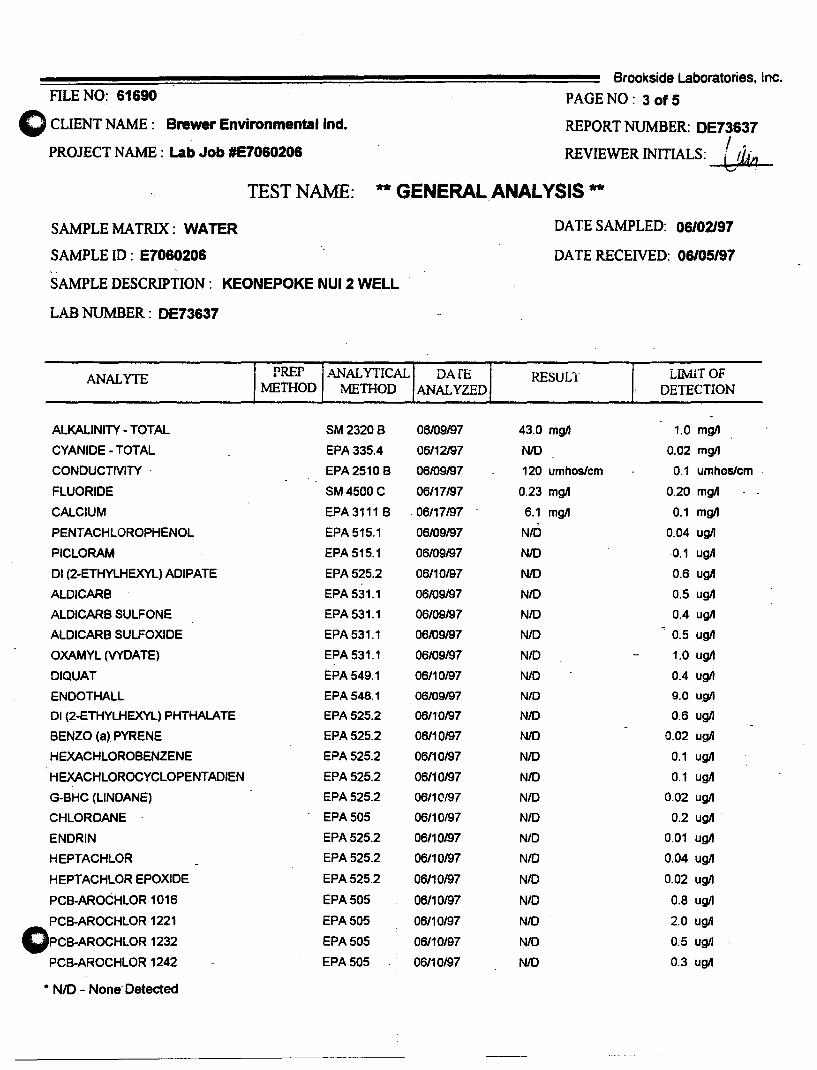
FILE NO: 61690 o CLIENT NAME: Brewer Environmental Ind.
PROJECT NAME: Lab Job tlE7060206
Brookside Laboratories. Inc.
PAGE NO : 3 of 5
REPORT NUMBER: OE73637 I " REVIEWER INITIALS: Ldta
TEST NAME: ** GENERAL ANAL YSIS **
SAMPLE MATRIX: WATER
SAMPLE ID: E7060206
SAMPLE DESCRIPTION: KEONEPOKE NUl 2 WELL
LAB NUMBER: OE73637
ANALYlE PREP ANALYTICAL METHOD METHOD
ALKALINITY - TOTAL SM2320B
CYANIDE - TOTAL EPA 335.4
CONDUCTIVITY . EPA2510B
FLUORIDE SM4500C
CALCIUM EPA3111 B
PENTACHLOROPHENOL EPA 515.1
PICLORAM EPA 515.1
01 (2-ETHYLHEXYL) ADIPATE EPA 525.2
ALDICARB EPA 531.1
ALDICARB SULFONE EPA S31.1
ALDICARB SULFOXIDE EPAS31.1
OXAMYL (VYDATE) EPAS31.1
DIQUAT EPA S49.1
ENDOTHALL EPA 548.1
01 (2-ETHYLHEXYL) PHTHALATE EPA 525.2
BENZO (a) PYRENE EPA 52S.2
HEXACHLOROBENZENE EPA 52S.2
HEXACHLOROCYCLOPENTADIEN EPAS2S.2
G-BHC (LINDANE) EPA 525.2
CHLORDANE EPA 50S
ENDRIN EPA 52S.2
HEPTACHLOR EPAS25.2
HEPTACHLOR EPOXIDE EPA 52S.2
PCB-AROCHLOR 1016 EPA 50S
PCB-AROCHLOR 1221 EPASOS
OPCB-AROCHLOR 1232 EPASOS
PCB-AROCHLOR 1242 EPASOS
• NID - None Detected
DArE ANALYZED
06109/97
06/12197
06109197
06/17197
06117197
06/09/97
06109/97
06/10197
06109/97
06/09/97
06109197
06/09197
06/10/97
06/09197
06110197
06110197
06110/97
06110197
06110/97
06/10/97
06/10m7
06110197
06/10/97
06/10/97
06110197
06110/97
06/10/97
DATE SAMPLED: 06/02197
DA TE RECEIVED: 06105/97
RESULT LIMlTOF DETECTION
43.0 mgJI 1.0 mgJI
N/D 0.02 mg/l
120 umhoslcm 0.1 umhoslcm
0.23 mgJI 0.20 mgJI
6.1 mgJI 0.1 mgJI
NIO 0.04 ugJI
NIO -0.1 ugJI
NIO 0.6 ugJI
NIO O.S ug/l
NIO 0.4 ugJI
NIO O.S ugJI
N/D 1.0 ug/l
NlD 0.4 ug/l
NID 9.0 ugJI
NIO 0.6 ugJI
NIO 0.02 ugll
N/O 0.1 ugJI
NIO 0.1 ugJI
N/O 0.02 ug/l
N/D 0.2 ug/l--
N/D 0.01 ug/J
NIO 0.04 ug/J
NIO 0.02 ugJI
NIO 0.8 ug/l
N/D 2.0 ug/l
NIO O.S ug/l
N/D 0.3 ugll

FILE NO: 61690
()cLIENT NAME: Brewer Environmental Ind.
PROJECT NAME: Lab Job 'E7060206
Brookside Laboratories, Inc.
PAGE NO : 40f5
REPORT NUMBER: DE73637
REVIEWER INITIALS: fTt c TEST NAME: ** GENERAL ANALYSIS **
SAMPLEMATRIX: WATER
SAMPLE ID: E7060206
SAMPLE DESCRIPTION: KEONEPOKE NUl 2 WELL
LAB NUMBER: DE73637
'1 ANALYTE- PREP - ANALYTICAL DATE
METHOD METHOD ANAL YZED
PCB-AROCHLOR 1248 EPA505 - 06110197
PCB AROCHLOR 1254 EPA 505 06110197
PCB AROCHLOR 1260 EPA 505 06/10197
2,3,7,8-TCD-DIOXIN EPA 1613 06118197
TOXAPHENE EPA 505 06/10197
AATREX-ATRAZINE EPA 525.2 06/10197
ALACHLOR EPA 525.2 06/10197
CARBOFURAN EPA 531.1 06/09197
2,4-0 EPA 515.1 06/09/97
DALAPON EPA 515.1 06/09197
DINOSEB EPA 515.1 06/09197
METHOXYCHLOR EPA 525.2 06110197
PRINCEP - SIMAZINE EPA 525.2 06/10197
ROUND UP (GLYPHOSA TE) EPA 547 06110197
2,4,5-TP (SILVEX) EPA 515.1 06/09/97
DBCP EPA 504.1 06/06197
ETHYLENEDIBROMIDE (EDB) EPA 504.1 06/06/97
-0 * NID - None Detected
DA IE SAMPLED: 06/02197
DA IE RECEIVED: 06/05/97
, RESULT I LIMIT OF
DETECTION
NID 0.1 ugJI
NID 0.1 ugJI
NID 0.2 ugIJ
NID 4.83 pgJI.
NID 1.0 ugJI
NID 0.1 ugJI
NID 0.1 ugJI
NID 0.9 ugJI
NID 0.1 ugJI
NID 1.0 ugJI
NID 0.1 ugJI
NID 0.1 ugJI
NID 0.07 ugJI
NID 6.0 ugll
N/D 0.1 ugIJ
N/D 0.02 ugIJ
NID 0.01 ugil

o FILE NO: 61690
CLIENT NAME: Brewer Environmental Ind.
PROJECT NAME: Lab Job #E7060206
Brookside Laboratories, Inc.
PAGE NO : 50f5
REPORT NUMBER: DE7~37 .
REVIEWER INITIALS: (~
TEST NAME: ** VOIAm.E ORGANIC COMPOUNDS **
SAMPLE MATRIX: WATER·
SAMPLE ID: E7060206
SAMPLE DESCRIPTION: KEONEPOKO NUl 2 WELL
LAB NUMBER: DE7363i
CODE ANALYTE
IE010 BENZENE .-
10040 CARBON TETRACHLORIDE
10050 CHLOROBENZENE
10130 1,2-DlCHLOROBENZENE
i0150 1,4-0ICHLOROBENZENE
10170 1,2-DICHLOROETHANE
10180 1,1-0/CHLOROETHENE
10219 CIS-1,2-0/CHLOROETHENE
10220 TRANS-1,2-0ICHLOROETHENE
10190 1,2-DICHLOROPROPANE
IE030 EiHYLBENZENE
10200 METHYLENE CHLORIDE
10207 STYRENE
10210 -ETRACHLOROETHENE-
IE040 TOLUENE
IM060 1,2,4-TRICHLOROBENZENE
10240 1,1,1-TRICHLOROETHANE
10260 1,1,2-TRICHLOR-OETHANE
10270 TRICHLOROETHENE
10275 1,2,3-TRICHLOROPROPANE
010290 VINYL CHLORIDE
IP810 XYLENES (TOTAL)
• NID - None Detected
ANALYTICAL METIIOD
EPA 524.2
EPA 524.2
EPA 524.2
EPA 524.2
EPA 524.2
EPA 524.2
EPA 524.2
EPA 524.2
EPA 524.2
EPA 524.2
EPA 524.2
EPA 524.2
EPA 524.2
EPA 524.2
EPA 524.2
EPA 524.2
EPA 524.2
EPA 524.2
EPA 524.2
EPA 524.2
EPA 524.2
EPA 524.2
DATE SAMPLED: 06102197
DA TERECEIVED: 06105197
DATE ANALYZED: 06/09197
ANALYST: DC
RESULT - LIMIT OF DETECTION -
( ugll ) ( ugll )
NID 0.5
NID 0.1_
NID 0.2
NID 0.1
NID 0.1
NID 0'.1
N/O 0.2
NID· 0.1
NID 0.1
NID 0.1
NID 0.1
NID 0.5
NID 0.2
NID 0.2
NID 0.5
N/O 0.2
N/O 0.1
N/O 0.1
N/O 0.1
N/D 0.2
NID 0.2
N/O 0.2
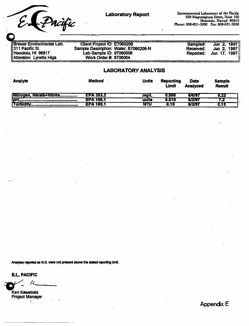
Laboratory Report
"
Environmental Laboratorv of the Pacific 930 Mapunapuna street. Suite 100
Honolulu. Hawaii 96819 Phone: 808-831-3090 fax: 808-831-3098
~~i!!!iS!~m:I~~i!iI!!!S9!!;S!m~~,~iiIjS!Si!!Bi!ims5:!~~.!!S:S~!!!Si*~iili!Sei!S1!i!S!ISS!i!Si!iS!iliiISSB8Bi!!iSSiii!!S!ISi~!ms!g!l!tllml!e!ssS!Su~!mSiS!S!8!9~X-&i:m rewer .Envlfonmental Lab. Client proJed 10: E7050205 samplea: Jun 2. 1 lib 1m
,311 Pacific st. Sample Description: Water. E7060206-N Received: Jun 2. 1997WJ : Honolulu. HI 96817 Lab Sample 10: 97060006 Reported: Jun 17. 1997f~ : Attention: Lynette Higa Work Ortler #: 9706004 ~~~ ~~~~, ~~~~~iiiS~'liBi!SI!!i8i8i!iliiiSmi;iIS~*,~l!:!!m.iSa!mSiSSi!i!m:$!i'!.m*:~~«;!i!!!sia!S!ii!S&,miS!~iS88iSeS!.ii!m!'!!!:i~,~Si!l!,~,~~,~:*»mm:4:
Analyte Method
e ............. .
LASORA TORY ANALYSIS
Units Reporting Umit
AnaIytes reported as N.D. were not present above the stated reporting limit.
E.L PACIFIC
~/L __
Ken Kawabata Project Manager
Date AnalyZed
Sample Result
Appendx E
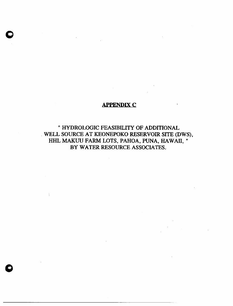
o
APPENDIXC
" HYDROLOGIC FEASffiILITY OF ADDITIONAL . WELL SOURCE AT KEONEPOKO RESERVOIR SITE (DWS),
HHL MAKUU FARM LOTS, PAHOA, PUNA, HAWAII, " BY WATER RESOURCE ASSOCIATES.
Hydrologic Feasibility of Additional Well Source at Keonepoko Reservoir Site (DWS), HHL Makuu. Farm Lots, Paboa, Puna, Hawaii
INTRODUCTION
Hawaiian Home Lands needs to develop a source of water supply for its
Makuu F armlot Subdivision located north of Pahoa town. One alternative being
considered is to drill a well at the Keonepoko Reservoir Site, which belongs to the
Hawaii County Department of Water Supply (see Figure 1). The site is located
alongside Highway 130 at an approximate elevation of 60S feet, just south of the
farm lots.
An existing deep well, Keonepoko Nui 1 ,-is located within the reservoir site
and it has an installed pump capacity of 700 gpm. This report discusses the
hydrologic feasibility of developing an additional well source within this reservoir
site to serve the water needs of the Makuu Fannlots Subdivision.
PAHOA AQUIFER SYSTEM
Boundaries. The proposed project is located within the Pahoa Aquifer
System in an area of high rainfall. The aquifer system, which is a part of the 564
square-mile Kilauea Hydrologic Sector, embraces a wedge-shaped area of 222 square
miles extending from Kilauea Crater eastward to the ocean between the Kilauea East
Rift Zone and the Volcano-Keaau Highway (see Figure 2).
Geology. The Pahoa Aquifer System is comprised chiefly of basaltic flank
flows of the Puna volcanic series. These basaltic flows are geologically young (30
to 10,000 years at the surface), relatively unweathered, highly permeable, and
typically yield water readily to wells. The lavas are dike-free, except in the Kilauea
East Rift zone.
Due to their young age and lack of weathering, the permeable basalts readily
absorb rainfall and streams and streamflows are essentially nonexistent

o Groundwater Recharge. Within the Pahoa Aquifer System, median rainfall
ranges from about 75 inches a year near Cape Kumukahi to about 190 inches near
the town of Mountain View. The estimated volume of rainfall amounts to 1,530
million gallons per day (mgd) and the estimated groundwater recharge amounts to
994 mgd, or approximately 65% of rainfall (Water Resources Protection, Plan,
. Commission on Water Resource Management June 1990).
Sustainable Yield. The sustainable yie.ld of the Pahoa Aquifer System has
been estimated in the 1990 Water Resources Protection Plan to be 435 mgd, or 44%
of groundwater recharge. Sustainable yield,· a term used in Hawaii to defme· the
amount of ground water that can be withdrawn fro~ an aquifer system, is. based'
upon selecting a head level which is a fraction of the original, or pre-development,
head
AVAILABILITY.OF GROUND WATER
.'
Existing Wells and Water Use. The only wells within a two-mile. radius. of
the Keonepoko site are the two Department of Water Supply Pahoa Wells 2A and
2B (2986-01, 02) located to the south and two private domestic wells (3185-01, 02)
located to the east These wells, plus the Keonepoko Nui Well, have a combined
total pump capacity of approximately 2.4 mgd and an average water withdrawal of
only 1.8 mgd (1990-91 data). .
The Pahoa area has an abundant supply of basal ground water of high quality ..
For the future, the Department of Water Supply has contemplated the driUing of
additional wells alternatively at the Keonepok~ reservoir and well site, the Pahoa
well field, or at another site in order to meet anticipated increases in water use and
improve system reliability (Hawaii County Water Use and Development Plan).
Groundwater Flow. The Keonepoko reservoir site is centrally located within
the Pahoa Aquifer System. This aquifer is the island's largest, in terms of
groundwater recharge (994 mgd) and sustainable yield (435 mgd).
Presumably, ground water tlows in a general eastward direction, from areas
of highest rainfall toward eventual discharge along the northeast coast of Puna.
Using the median annual rainfall map (CWRM. 1990) the magnitude of groundwater
2
o flowing eastward through the Keonepoko-Pahoa area is of the order of 50 mgd per
mile width. This large amount together with the occurrence of a 600-foot thick basal
lens having a head of 15 to 17 feet, the development of individual well fields with a
pump capacity of at least 5 mgd should be easily attainable without any adverse .
effect on the aquifer's sustainable yield and water quality.
o
Aquifer Cllaracteristics/We/l Spacing. The basal aquifer underlying the
Keonepoko-Pahoa area consists of extensive basaltic lava flows having hydrologic
characteristics which rival those of the water-rich Pearl Harbor aquifer on Oahu.
Fortunately, the Hawaii County Department of Water Supply conducted a reliable
~e-day pumping test (1977) on the Keonepoko Nui Well and the data confirms the
highly penneable nature of the Puna basalts in the Keonepoko-Pahoa area. With an
aquifer penetration of only 65 feet (depth of well = -50 feet, msl), the well has
specific ~ell capacity of 1600 gpm per foot drawdown, exceeding the performance
of wells in the Pearl Harbor aquifer.
The drawdown and recovery of the Keonepoko Nui Well were essentially
instantaneous and during the three days of pumping at 1,000 gpm, the well exhibited
a stable drawdown of only 0.6 feet (see Figure 3). The chloride content of the well
was also stable at 4.0 mgtl. The temperature of pumped water measured 67.5°F
during the night. Elevated temperatures of up to 71°F were measured during the da~time and may have been caused by the use of recirculated pumped water to cool
the diesel engine.
The Pahoa 2A Well, located approximately two miles south, has a specific
well capacity of 628 gpm per foot of drawdO\\TI (about 40% that of the Keonepoko
Nui'Vell). However, the well may not have been fully developed, based on a test
pumping rate of only 314 gpm and a drawdown of 0.5 feet.
CONCLUSION
The Keonepoko-Pahoa area is underlain by a thick, highly penneable basalt
aquifer of high quality (6 mgtl chlorides). Based on a head of 15 to 17 feet, the
basal lens in the area extends 600 feet or more below sea level. Ground water in the
aquifer presumably flows in a general eastward direction from areas of highest
rainfall toward ultimate discharge along the northeastern coast of Puna.
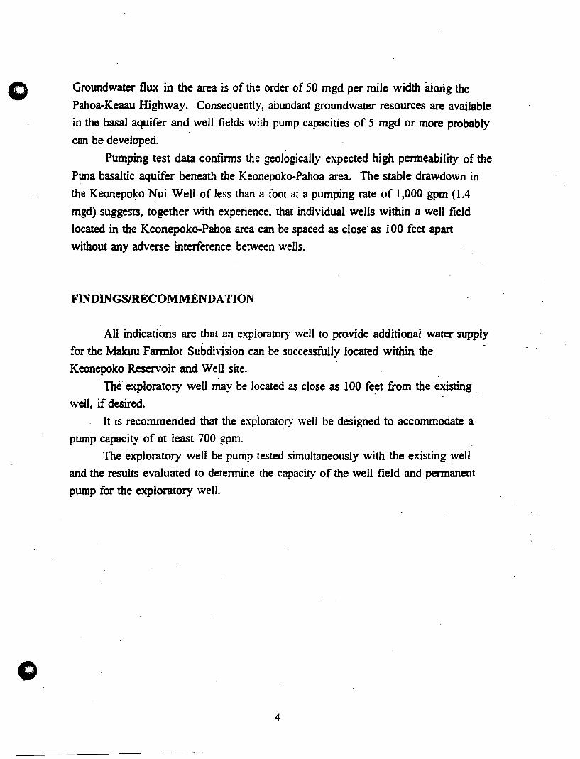
c Groundwater flux in the area is of the order of 50 mgd per mile width wong the
Pahoa-Keaau Highway. Consequently, abundant groundwater resources are available
in the basal aquifer and well fields with pump capacities of 5 mgd or more probably
can be· developed.
Pumping test data confinns the geologically expected high penneability of the
Puna basaltic aquifer beneath the Keonepoko-Pahoa area. The stable drawdown in
the Keonepoko Nui Well of less than a foot at a pumping rate of 1,000 gpm (1.4
mgd) suggests, together with experience, that individual wells within a well field
located in the Keonepoko-Pahoa area can be spaced as close as 100 feet apart
without any adverse interference between wells.
FINDINGSIRECOMMENDATION
All indications are that an exploratory well to provide additional water supply
for the Makuu Fannlot Subdivision can be successfully located within the
Keonepoko Reservoir and Well site .
. The· exploratory well may be located as close as 1 00 fe~t from the existing ..
well, if desired.
It is recommended that the exploratory well be designed to accommodate a
pump capacity of at least 700 gpm.
The exploratory well be pump tested simultaneously with the existing well
and the results evaluated to detennine the capacity of the well field and pennanent
pump for the exploratory well.
4

0,;
\
I .,
,!
. ....
---'-07"
, \
'. I
o I mile I I
Sale
LEGEND • KEONEPOKO NUl WELL-1
• PAHOA DEEP WELL 2A & 28
• MUNICIPAL WATER SERVICE AREA CJ PROPOSED WATER DEVELOPMENT AREA
® Source and Reservoir DtMtIopment. @ Transmission Main DewIopment
Figure 1. Pahoa Area
REGIONAL WATER DEVELOPMENT PLAN (MOdified after FIQ. 1.9-1, Hawaii County Water Use and Development Plan, Review Draft. 2192
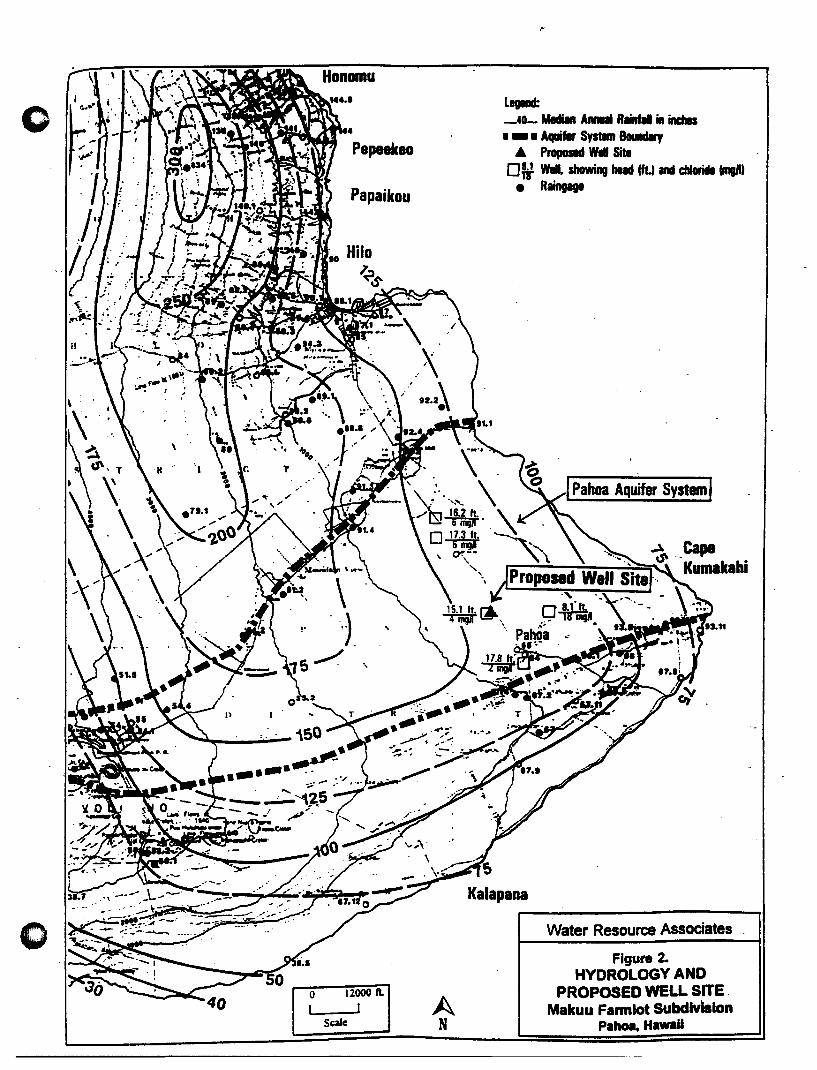
o Papaikou
()
A N [2:]120001\.
I J SQlc
.~
legend: _40- MecIIII A ...... R .... in incMs • -. Aqui" SystIm 80IIIdIry
• Proposed Wei Site o ~ Will. showing had 1ft.) and c:IIIora ImgJIt
• Raingage
Kalapana
.J Pahoa Aquifer System I
Water Resource Associates
Figure 2. HYDROLOGY AND
PROPOSED WELL SITE Makuu Fannlot Subdlvhllon
Pahoa,HawaU

e
:n 1 w
gpm
PUMPING TEST RECORD Keonepoko Nui Well (3188-01), Pl;Jna, HI
Date of Test: Dec. 6-9,1,977
o
feet
1600 ~------------------------------------'---------------------------------------' 1-
1500
1400
1300
1200
1100 -
1000
800
600
500
400 -
300 - I I
i I ____ --:.i . ____ ~.
200 Pump Test by , \".... Hawaii County DWS
• I 100 -
a a 500
Wat.r R •• ouro. A •• oclat •• 07:J\PulllpT •••
1000 1500 2000 2500 3000 Minutes since pumping began
f------lll- a
- 1
", -2
- - 3
-4
-5
-6
-7
3500 4000 4500 5000
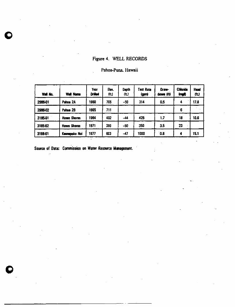
Figure 4. WELL RECORDS
Pahoa-Puna. Hawaii
Yea, Elev. Depth Test Rate Draw· CbIoride Had WII No. WaI Name Drilled 1ft.) Ift.1 1- daMI (ftt - 1ft.)
298&01 Pahoa 2A 1960 705 -50 314 0.5 4 17.8
298&02 Pahoa 28 1965 711 6
3185-01 . Hawn Shores 1964 402 -44 425 1.7 18 10.6
3185-02 Hawn Shores 1971 380 -50 350 3.5 23
3188-01 KeOnepoko Nui 1977 603 -47 1000 0.6 4 15.1
Source of Data: Commission on Water Resource Management.
o

APPENDIXD
WELL PUMPING UNIT SPECIFICATIONS
o
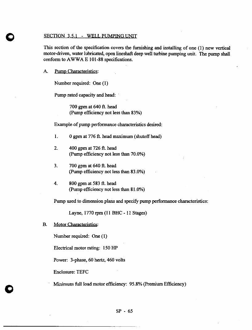
o
SECTION 3.5.1 - WELLPUMPINGUNIT
This section of the specification covers the furnishing and installing of one (1) new vertical motor-driven, water lubricated, open lineshaft deep well turbine pumping unit. The pump shall conform to A WW A E 101-88 specifications.
A. Pump Characteristics:
Number required: One (1)
Pump rated capacity and head:
700 gpm at 640 ft. head (pump efficiency not less than 83%)
Example of pump performance characteristics desired:
1. 0 gpm at 776 ft. head maximum (shutoff head)
2. 400 gpm at 726 ft. head (Pump efficiency not less than 70.0%)
3. 700 gpm at 640 ft. head (Pump efficiency not less than 83.0%)
4. 800 gpm at 583 ft. head (pump efficiency not less than 81.0%)
Pump used to dimension plans and specify pump performance characteristics:
Layne, 1770 rpm (11 BHC - 11 Stages)
B. Motor Characteristics:
Number required: One (1)
Electrical motor rating: 150 HP
Power: 3-phase, 60 hertz, 460 volts
Enclosure: TEFC
Minimum full load motor efficiency: 95.8% (Premium Efficiency)
SP - 65
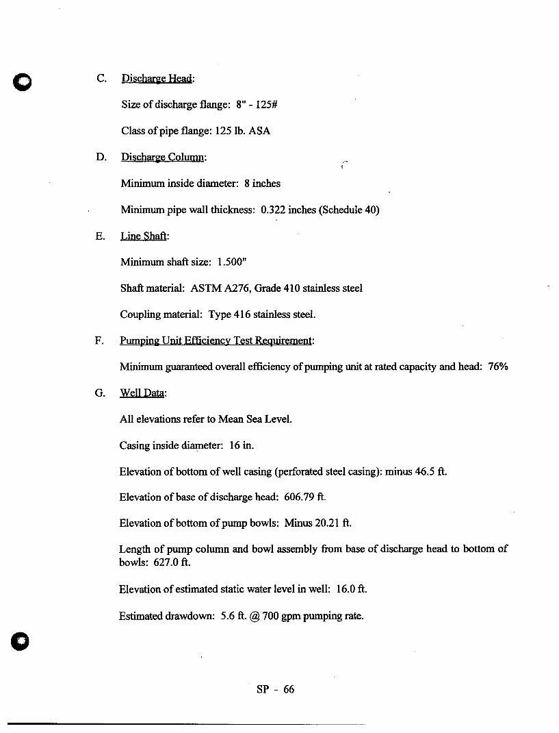
o
C. DischarKe Head:
Size of discharge flange: 8" - 125#
Class of pipe flange: 125 lb. ASA
D. Dischar~e Column:
Minimum inside diameter: 8 inches
Minimum pipe wall thickness: 0.322 inches (Schedule 40)
E. Line Shaft:
Minimum shaft size: 1.500"
Shaft material: ASTM A276, Grade 410 stainless steel
Coupling material: Type 416 stainless steel.
F. Pumpin~ Unit Efficiency Test Reqyirement:
Minimum guaranteed overall efficiency of pumping unit at rated capacity and head: 76%
G. Well Data:
All elevations refer to Mean Sea Level.
Casing inside di~eter: 16 in.
Elevation of bottom of well casing (perforated steel casing): minus 46.5 ft.
Elevation of base of discharge head: 606.79 ft.
Elevation of bottom of pump bowls: Minus 20.21 ft.
Length of pump column and bowl assembly from base of discharge head to bottom of bowls: 627.0 ft.
Elevation of estimated static water level in well: 16.0 ft.
Estimated drawdown: 5.6 ft. @ 700 gpm pumping rate.
SP - 66
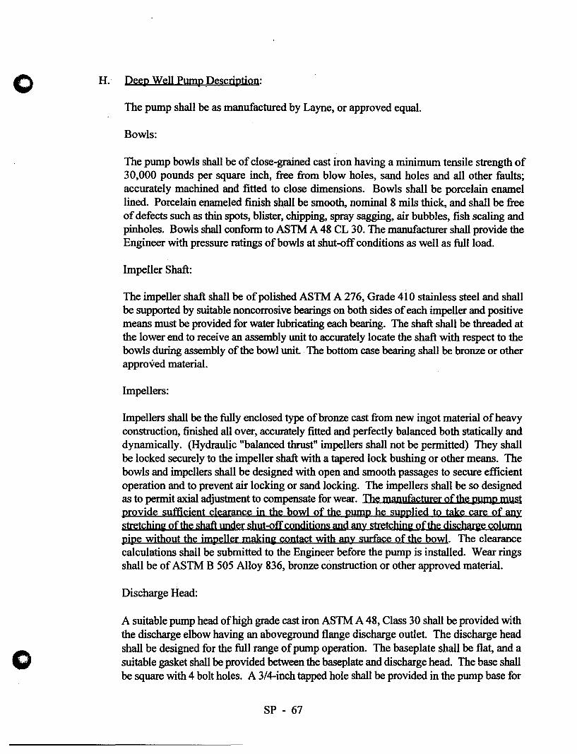
()
o
H. Deep Well Pump .Description:
The pump shall be as manufactured by Layne, or approved equal.
Bowls:
The pump bowls shall be of close-grained cast iron having a minimum tensile strength of 30,000 pounds per square inch, free from blow holes, sand holes and all other faults; accurately machined and fitted to close dimensions. Bowls shall be porcelain enamel lined. Porcelain enameled finish shall be smooth, nominal 8 mils thick, and shall be free of defects such as thin spots, blister, chipping, spray sagging, air bubbles, fish scaling and pinholes. Bowls shall confonn to ASTM A 48 CL 30. The manufacturer shall provide the Engineer with pressure ratings of bowls at shut-off conditions as well as full load.
Impeller Shaft:
The impeller shaft shall be of polished ASTM A 276, Grade 410 stainless steel and shall be supported by suitable noncorrosive bearings on both sides of each impeller and positive means must be provided for water lubricating each bearing. The shaft shall be threaded at the lower end to receive an assembly unit to accurately locate the shaft with respect to the bowls during assembly of the bowl unit. The bottom case bearing shall be bronze or other approved material.
Impellers:
Impellers shall be the fully enclosed type ofbronze cast from new ingot material ofheavy construction, finished allover, accurately fitted and perfectly balanced both statically and dynamically. (Hydraulic "balanced thrust" impellers shall not be permitted) They shall be locked securely to the impeller shaft with a tapered lock bushing or other means. The bowls and impellers shall be designed with open and smooth passages to secure efficient operation and to prevent air locking or sand locking. The impellers shall be so designed as to pennit axial adjustment to compensate for wear. The manufacturer of the pump must provide sufficient clearance in the bowl of the pump he su'pplied to take Care of any stretchini of the shaft under shut-off conditions and any stretchini of the discme column pipe without the impeller makini contact with anY surface of the bowl. The clearance calculations shall be submitted to the Engineer before the pump is installed. Wear rings shall be of ASTM B 505 Alloy 836, bronze construction or other approved material.
Discharge Head:
A suitable pump head ofhigh grade cast iron ASTM A 48, Class 30 shall be provided with the discharge elbow having an aboveground flange discharge outlet. The discharge head shall be designed for the full range of pump operation. The baseplate shall be flat, and a suitable gasket shall be provided between the baseplate and discharge head. The base shall be square with 4 bolt holes. A 314-inch tapped hole shall be provided in the pump base for
SP - 67

o
connection to the air relief line which will allow the relief of air in the space between the casing and the pump column. An additional 3/4-inch tapped hole shall be provided in the pump base to allow the air line for water level detennination to pass through the base into the area between the column and casing. The discharge head shall be provided with a water lubrication arrangement that will allow wetting of the lineshaft bearings. The stuffing box shall be precision machined to guide the head shaft and shall be provided with a Chesterton #442 Split Seal or approved equal. A water slinger shall also be provided to prevent water from entering the motor from the bottom. The design shall pennit the drive shaft to be coupled above the stuffing box. Discharge head used for design is Layne SDH head.
Discharge Column Assembly:
The discharge column assembly shall confonn to the following requirements.
1. Dischar"e Column Pipe Size
The pipe for the discharge column shall have a nominal inside diameter of not less than that specified.
2. Discharie Column Pipe Description
The discharge column pipe shall be Schedule 40 steel pipe conforming to ASlM Specification A 53, Grade A and shall be coated with zinc inside and outside by the hot-dip process. Each section of the column shall have straight threads with ends accurately machined to fonn a butt joint to insure accurately assembled column length and perfect alignment. The pipe shall be furnished in interchangeable sections of not more than 10 feet in length. The Schedule 40 pipe specified is the minimum weight to be furnished. The Contractor shall furnish and install a heavier weight of pipe should same be required to satisfy pressure or structural requirements for his proposed pump installation.
3. Certification of Discharge Column Pipe
A certificate must be submitted to the Department of Water Supply before the pump is installed verifying the following:
a.
b.
c.
The thickness of the discharge column pipe furnished is as specified.
The pipe supplied confonns to ASTM Specification A 53, Grade A.
The pipe has been coated with zinc inside and outside by the hot-dip process.
SP - 68
o
o
4. Steel Column Coyplin~s
The pipe shall be furnished to interchangeable sections not more than 10 feet in length with lathe cut threads and shall be fastened with threaded sleeve type couplings. The combination column couplings shall be made of ASTM A 48, Class 30 cast iron with aligning spider cast integrally. The butt joint connection shall insure proper alignment.
5. Lineshafi
The lineshaft furnished shall be the minimum size, and the material shall be ASTM A 276, Type 410 stainless steel. Should the manufacturer require a larger sized shaft, he shall provide the required larger size. The lineshaft shall be furnished in interchangeable sections 10 feet in maXimum length. The shaft (10 feet) shall be straight within 0.003" total indicator reading. Lineshaft surface finish shall be 8 to 16 rms.
6. Lineshaft Couplin~
The lineshaft shall be connected with Type 416 stainless steel threaded couplings. The couplings shall be designed with a safety factor of 1-l/2 times the shaft safety factor and shall have a left-hand thread to tighten during the pump operation. An adjusting method shall be provided at the top of the shaft to allow impeller adjustment by means of an adjusting nut to provide a positive l~king device. Each coupling shall have a l/8-inch diameter sight hole to ensure the lineshafts are butt connected.
7. Water Lubricated Graphalloy Bearin~
The pump assembly shall have a full-length water lubricated graphalloy bearing properly spaced in each section of the pipe columns to maintain alignment of the shafting and to prevent vibration. To ensure adequate lubrication and to flush any sand or grit, the graphalloy bearings inside surfaces shall be spirally grooved or provided with grooves of other approved configuration. The graphalloy bearing . shall be lead-free, tin babbitt material Grade OM 205.3 as manufactured by Graphite Metallizing Corporation, 1050 Mepperhan A ve., Yonkers, New York 10702 (do not substitute). The pump contractor and/or supplier shall submit to the Engineer for approval the minimum water lubrication rate necessary to ensure adequate lubrication to the bearings supplied for the entire assembly.
SP - 69
o
o
8. Suction Case
The suction case shall be the venturi type with streamline vanes conducting water from the inlet to the eye of the first stage impeller. The suction nozzle bearing shall be bronze, grease packed, extra long sleeve type with a sand collar for protection against sand and grit.
Strainer:
The strainer shall be of the tapered cylindrical type and shall be attached to the bottom of the suction pipe by means of a threaded connection. The net area of the screen openings shall be not less than twice the area of the pump suction opening. The strainer shall be stainless steel.
Base Plate:
A cast iron base plate shall be furnished for mounting the pump discharge head and shall be properly fitted in as part of the concrete pump foundations to seal off water and other contaminants from entering the well. The base plate shall be surface machined and drilled, and tapped to fit the pump discharge head. The opening of the base plate shall be large enough to allow the installation of the pump bowl assembly, pump discharge column, air breather pipeline, and well water level recorder air line.
I. Motor Description:
The motor shall be a normal torque, normal starting current, weatherproof, vertical hollow shaft, squirrel cage induction motor with NEMA Totally Enclosed Fan Cooled (TEFC) enclosure and shall conform to the Standards of the National Electrical Manufacturers Association. The motor shall be rated for 480 VAC, 3 PH, 60 HZ, 1,800 RPM, 1.15 Service Factor, premium efficiency. Minimum full load efficiency shall be 95.8 percent.
The motor shall have a horsepower rating of not less than specified and shall be General Electric Tri-Class Vertical Hollow-Shaft Induction Motor; Westinghouse Vertical HollowShaft; or approved equal. The motor shall have adequate capacity to drive the pump continuously under the head specified with a temperature rise of not more than 40 degrees C.
The motor shall be equipped with space heaters rated 120 VAC, 1 PH, with wattage as required by the motor manufacturer. Space heater loads shall be brought into the motor terminal box or it shall have a separate terminal box of its own for conduit connection.
SP - 70
o
o
The motor shall have an efficiency of not less than that specified when operating under full-load conditions. The bearings in the motor shall be oil lubricated. The motor thrust bearings shall have ample capacity to carry the thrust loads of the pump thrust and weights of the pump shaft and pump rotating element with the pump operating at shut-off head conditions. The thrust bearing shall be of such size that the average life rating is based on 5 years of continuous operation.
The motor shall be designed to prevent reverse rotation when the unit is shut down.
The selection of the motor shall be the responsibility of the Contractor and Pump Manufacturer and must meet the approval of the Engineer before it is ordered.
Manufacturer's certified copies of test run on a motor of the same type, size and model as the one being furnished shall be forwarded to the pump supplier for inclusion in the bound sets for submittal to the Engineer. Test data shall include:
1. A.C. winding resistance
2. No load current
3. Full load current
4. Locked rotor current
5. Starting torque
6. Motor efficiency at 50, 75, and 100% full load
7. Power factor at 50, 75, and 100% full load
8. Power factor at full load with 90 and 110% rated voltage
J. Spare Parts:
Each bidder shall supply and deliver the following list of spare parts to the Department of Water Supply Hilo Baseyard.
One (1) extra set of bearings for the pump motor.
One (1) extra set mechanical seal for the pump.
SP - 71
APPENDIXE
FUTURE WELL SITE LOCATION
BENJAMIN J. CAYETANO GOVERNOR Of HAWA"
MICHAEL D. WILSON CHAlIl'ERSON
TO:
FROM:
STATE OF HAWAII DEPARTMENT OF LAND AND NATURAL RESOURCES
COMMISSION ON WATER RESOURCE MANAGEMENT P. o. BOX 821
HONOLULU. HAWAII 96809
June 8, 1998
Mr. Thomas Arizumi, P.E., Chief Environmental Management Division Department of Health
Timothy E. Johns, Deputy Directo~~' ~ Commission on Water Resource Management
ROBERT G. GIRALO DAVID A. NOBRIGA LAWRENCE H. MilKE
RICHARD H. COX HERBERT M. RICHARDS. JR.
TIMOTHY E. JOHNS OEPUTY OIAECTOR
SUBJECT: Keonepoko Nui 2 Well Engineering Report
EMD/SDWB FILE NO.:
Thank you for the opportunity to review the subject document. Our comments related to water resources are marked below.
In general, the CWRM strongly promotes the efficient use of our water resources through conservation measures and use of alternative non-potable water resources whenever available, feasible, and there are no harmful effects to the ecosystem. Also, the CWRM encourages the protection of water recharge areas which are important for the maintenance of streams and the replenishment of aquifers.
[ x ] We recommend coordination with the county government to incorporate this project into the county's Water Use and Development Plan.
[] We are concerned about the potential for ground or surface water degradation/cont:uain:rlloii and recommend that approvals for this project be conditioned upon a review by the State Department of Health and the developer's acceptance of any resulting requirements related to water quality.
A Well Construction Pennit and/or a Pump Installation Permit from the CWRM would be required before ground water is developed as a source of supply for the project.
The proposed water supply source for the project is located in a designated water management area, and a Water Use Pennit from the CWRM would be required prior to use of this source.
Groundwater withdrawals from this project may affect streamt1ows. This may require an instream flow standard amendment.
If the proposed project diverts additional water from streams or if new or modified stream diversions are planned, the project may need to obtain a stream diversion works permit and petition to amend the interim instream flow standard for the affected stream(s).
[] If the proposed project performs any work within the bed and banks of a stream cbannel, the project may need to obtain a stream cbannel alteration permit and a petition to amend the interim instream flow standard for the affected stream(s).
We recommend that no development take place affecting highly erodible slopes which drain into streams within or adjacent to the project.
OTHER:
If there are any questions, please contact Mr. Ryan lmata at 587-0255.
~. -'[ COMMISSION ON WATER RESOURCE MANAGEMENT (4/98)
FROM:_.....:E=d'--______ DATE:_...;;.G:~/'-Il_fI-1..L...:6::;..· __ SUSPENSE DATE _______ _ / 1
INIT. PLEASE:
}
_I BAUER, G. ~ _ LUM, A.
~HING' F. _ NAKAMA, L.
FUJII, N. _ NAKANO, D. HARDY, R. ~ ..:!::- OHYE, M.
_ HIGA, D. '\ SAKODA, E. HIRANO, E. 5(1 SUBIA, S. ICE, C. _ SWANSON,
..::::z... IMATA, R. ~ _ UWAINE, J.
~AI' R. _ UYENO, D. _ IMURA, I. _ YODA, K.
JO~iT. ~~ tvl Wu
__ Approval See Me __ Signature ~ Review & Comment
+--=- __ Information Take Action ~~'-I*' ~~ ..-3.. Type Draft
-2.. Type Final
Ik /..{;ti-). ~ ~~~v~· 'ur:~~.~ ~nl.A~k.~
V ;fk- ~ -6/! ~ .. 1 7 ~ 1.4 (q .~" v-p. ~Tt.;t:r- A ~ • rP
OfL

--BENJAMIN J. CAYETANO
GOVERNOR OF HAWAII
STATE OF HAWAII ~n~1AY I An: 57
LAWRENCE MilKE DIRECTOR OF HEALTH
DEPARTMENT OF HEALTH In reply, please refer 10: P.O. BOX 3378 EMO I SOWS
HONOLULU, HAWAII 96801
April 23, 1998
The Honorable Michael D. Wilson Chairman of the Board Attn: Mr. Edwin Sakoda, Acting Deputy Director Department of Land and Natural Resources 1151 Punchbowl Street Honolulu, Hawaii 96813
Dear Mr. Wilson:
SUBJECT: PROPOSED SOURCE OF POTABLE WATER
Enclosed for your review and comments is a copy of the engineering report for the following source:
Keonepoko - Nui 2 Well State Well No. 8-3188-02 Pahoa, Puna, Hawaii
This report has been prepared pursuant to Hawaii Administrative Rules, Title 11, Chapter 20, Rules Relating to Potable Water Systems, section 11-20-29.
The Department of Health will use your comments in determining the potential impacts which may result by the proposed project.
Please submit your comments to the Safe Drinking Water Branch within 30 days from the date of this letter. You may also return the engineering report to this office if you do not need it for future reference.
If you should have any questions, please call the Safe Drinking Water Branch, Engineering Section, at 586-4258.
s(~cerelY,
'/:Jid;f!/k /~THOMAS E. ARIZUMI, P.E., Chief ~Environmental Management Division
QK:la
Enclosure
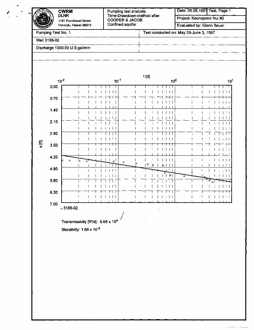
CWRM DLNR 1151 Punchbowl Street
Honolulu, Hawaii 96813
Pumping test analysis Time-Drawdown-method after COOPER & JACOB Confined aquifer
Project: Keonepoko Nui #2
Evaluated by: Glenn Bauer
Pumping Test No. 1 Test conducted on: May 29-June 3, 1997
Well 3188-02
Discharge 1000.00 U.S.gal/min
t[d] 10-2 10-1
0.00 I I I I I I I I I I I I I I I I I I I I I I I I
I I I I I I I I I I I I I I I I I I I I I I I I
0.70 I I I I I I I I I I I I I I I I I I I I I I I I I I I I I I I I I I I I I I I I I I I I I I I I
1.40 I I I I I I I I I I I I I I I I I I I I I I I I I I I I I I I I I I I I I I I I I I I I I I I I
2.10 I I I I I I I I I I I I I I I I I I I I I I I I I I I I I I I I I I I I I I I I I I I I I I I I
2.80 , I I I I I I I , I I I , I I , I I I I I I I I
g 3.50 II)
I I I I I I I I I I I I I I I I I I I I I I I I
I I I I I I I I I I I I I I I I I I I I I I I I I I I I I I I I I I I I I I I I I I I I I I I I
4.20 ~~lllol o I I I I I I I I I I I I I I I I I I III"Tfr ~ 10 10 I 10 II I I I I I I I I I
4.90 I I I I I I I I I ~ I I I I I I I I I I I I I I I I I I I I I I jO I ~I I I I I I
5.60 I I I I I I I I I I I I I I I I I I Pol l'"""t-+-I.... I I I I I I I I I I I I I I I I I I I I I I I I
6.30 I I I I I I I I I I I I I I I I I I I I I I I I
I I I I I I I I I I I I I I I I I I I I I I I I
7.00 03188-02
Transmissivity [ft2/d]: 6.68 x 10⁴ /
Storativity: 1.69 x 10⁻⁵
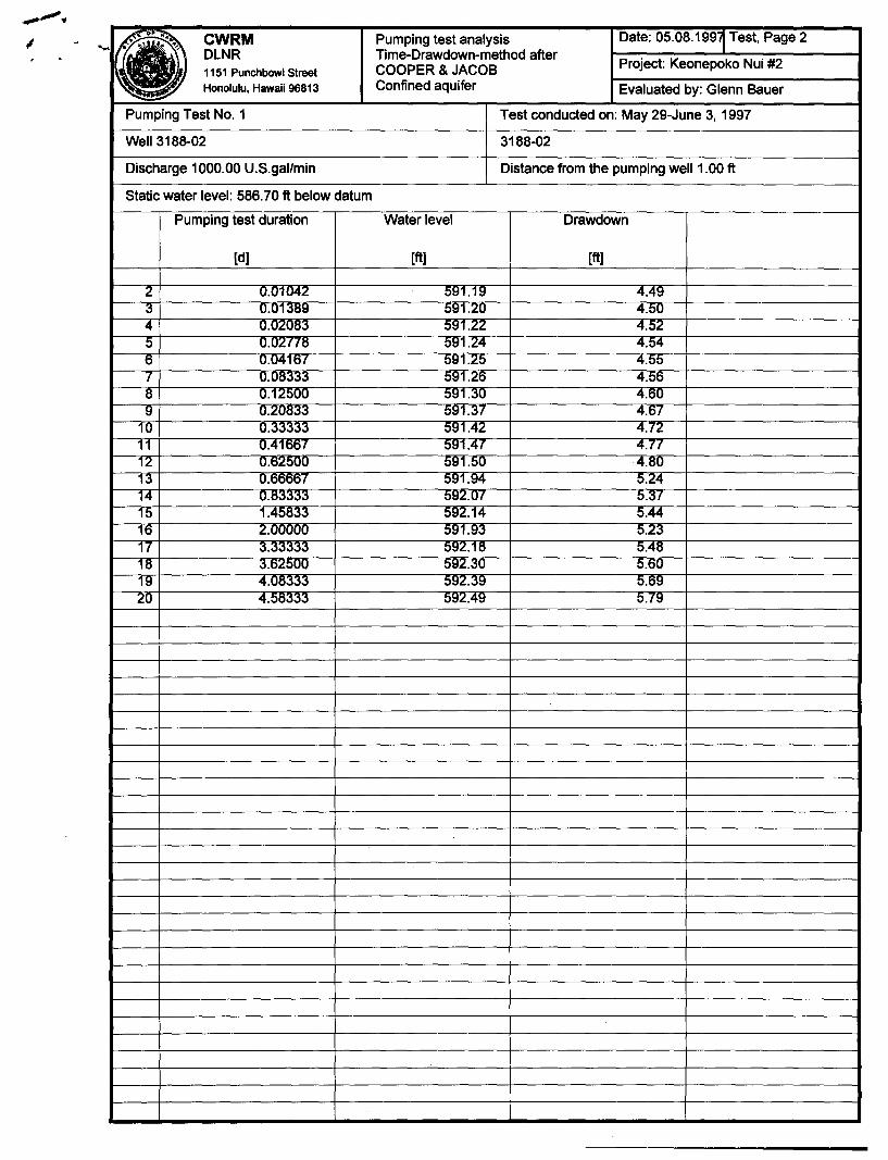
I
• CWRM Pumping test analysis Date: 05.08.199~ Test, Page 2 DLNR Time-Drawdown-method after
Project: Keonepoko Nui #2 1151 Punchbowl Street COOPER & JACOB Honolulu, Hawaii 96813 Confined aquifer Evaluated by: Glenn Bauer
~
Pumping Test No.1 Test conducted on: May 29-June 3, 1997
Well 3188-02 3188-02
Discharge 1000.00 U.S.gal/min Distance from the pumping well 1.00 ft
Static water level: 586.70 ft below datum
Pumping test duration Water level Drawdown
[d] [ft] [ft]
2 0.01042 591.19 4.49 3 0.01389 591.20 4.50 4 0.02083 591.22 4.52 5 0.U2f7tS 591.24 4.54 6 0.04167 591.25 4.55 7 0.08333 591.26 4.56 8 0.120UU 591.30 4.ou 9 0.2U833 591.37 4.07
10 0.33333 591.42 4.72 11 0.41667 591.47 4.77 12 0.0200U 591.5U ·4.8U 13 0.60667 591.94 5.24 14 0.83333 592.07 5.37 15 1.45833 592.14 5.44 16 2.000UO 591.93 :>.23 17 3.33333 592.18 5.48 18 3.62500 592.30 5.60 19 4.U8;:S;:S;:S 592.39 5.69 20 4.58333 592.49 :>.79
..
•
Chapter 343, Hawaii Revised Statutes (HRS)
DRAFT Environmental Assessment in Anticipation of
A Negative Declaration
KEONEPOKO - NUl 2 EXPLORATORY WELL
PAHOA, PUNA, HAWAII
Prepared for:
Department of Hawaiian Home Lands State of Hawaii
Prepared by:
Engineers Surveyors Hawaii, Inc. 1020 Auahi Street
Suite No.1, Building No.6 Honolulu, Hawaii 96814
June, 1996/
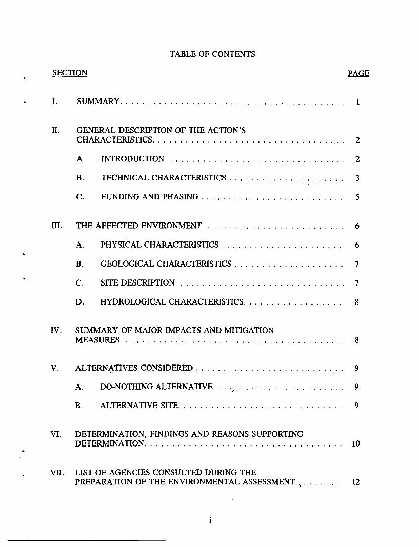
•
TABLE OF CONTENTS
SECTION PAGE
I. SUMMARY. . . . . . . . . . . . . . . . . . . . . . . . . . . . . . . . . . . . . . . .. 1
II. GENERAL DESCRIPTION OF THE ACTION'S CHARACTERISTICS. . . . . . . . . . . . . . . . . . . . . . . . . . . . . . . . . .. 2
A. INTRODUCTION. . . . . . . . . . . . . . . . . . . . . . . . . . . . . . .. 2
B. TECHNICAL CHARACTERISTICS . . . . . . . . . . . . . . . . . . . .. 3
C. FUNDING AND PHASING. . . . . . . . . . . . . . . . . . . . . . . . .. 5
III. THE AFFECTED ENVIRONMENT. . . . . . . . . . . . . . . . . . . . . . . .. 6
A. PHYSICAL CHARACTERISTICS . . . . . . . . . . . . . . . . . . . . .. 6
B. GEOLOGICAL CHARACTERISTICS . . . . . . . . . . . . . . . . . . .. 7
C. SITE DESCRIPTION . . . . . . . . . . . . . . . . . . . . . . . . . . . . .. 7
D. HYDROLOGICAL CHARACTERISTICS. . . . . . . . . . . . . . . . .. 8
IV. SUMMARY OF MAJOR IMPACTS AND MITIGATION MEASURES ........................................ 8
V. ALTERNATIVES CONSIDERED. . . . . . . . . . . . . . . . . . . . . . . . . .. 9 ~
A. DO-NOTHING ALTERNATIVE ... #. • • • • • • • • • • • • • • • • • •• 9
B. ALTERNATIVE SITE. . . . . . . . . . . . . . . . . . . . . . . . . . . . .. 9
VI. DETERMINATION, FINDINGS AND REASONS SUPPORTING DETERMINATION. . . . . . . . . . . . . . . . . . . . . . . . . . . . . . . . . . .. 10
VII. LIST OF AGENCIES CONSULTED DURING THE PREPARATION OF THE ENVIRONMENTAL ASSESSMENT... . . . . .. 12
1
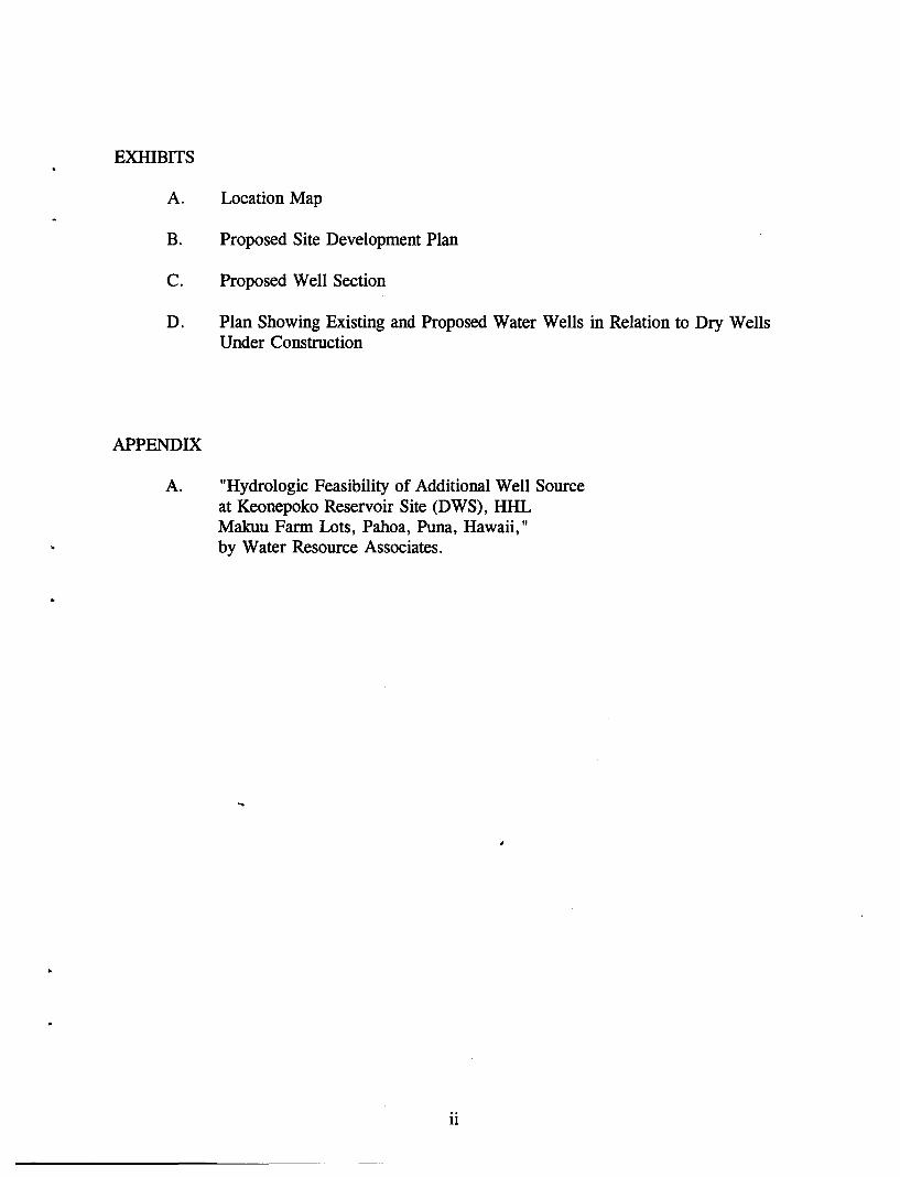
EXHIBITS
A. Location Map
B. Proposed Site Development Plan
C. Proposed Well Section
D. Plan Showing Existing and Proposed Water Wells in Relation to Dry Wells Under Construction
APPENDIX
A. "Hydrologic Feasibility of Additional Well Source at Keonepoko Reservoir Site (DWS), HHL Makuu Farm Lots, Pahoa, Puna, Hawaii," by Water Resource Associates.
ii
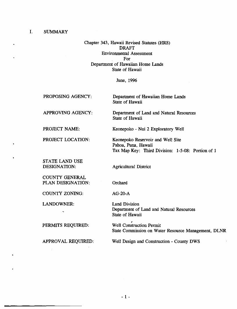
I. SUMMARY
Chapter 343, Hawaii Revised Statutes (HRS) DRAFT
Environmental Assessment For
Department of Hawaiian Home Lands State of Hawaii
PROPOSING AGENCY:
APPROVING AGENCY:
PROJECT NAME:
PROJECT LOCATION:
STATE LAND USE DESIGNATION:
COUNTY GENERAL PLAN DESIGNATION:
COUNTY ZONING:
LANDOWNER:
PERMITS REQllRED:
APPROVAL REQUIRED:
June, 1996
Department of Hawaiian Home Lands State of Hawaii
Department of Land and Natural Resources State of Hawaii
Keonepoko - Nui 2 Exploratory Well
Keonepoko Reservoir and Well Site Pahoa, Puna, Hawaii Tax Map Key: Third Division: 1-5-08: Portion of 1
Agricultural District
Orchard
AG-20-A
Land Division Department of Land and Natural Resources State of Hawaii
~
Well Construction Permit State Commission on Water Resource Management, DLNR
Well Design and Construction - County DWS
- 1 -
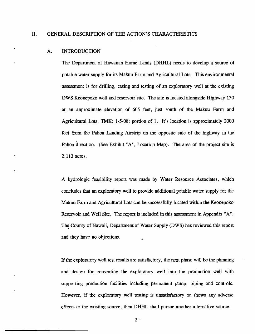
II. GENERAL DESCRIPTION OF THE ACTION'S CHARACTERISTICS
A. INTRODUCTION
The Department of Hawaiian Home Lands (DHHL) needs to develop a source of
potable water supply for its Makuu Farm and Agricultural Lots. This environmental
assessment is for drilling, casing and testing of an exploratory well at the existing
DWS Keonepoko well and reservoir site. The site is located alongside Highway 130
at an approximate elevation of 605 feet, just south of the Makuu Farm and
Agricultural Lots, TMK: 1-5-08: portion of 1. It's location is approximately 2000
feet from the Pahoa Landing Airstrip on the opposite side of the highway in the
Pahoa direction. (See Exhibit "A", Location Map). The area of the project site is
2.113 acres.
A hydrologic feasibility report was made by Water Resource Associates, which
concludes that an exploratory well to provide additional potable water supply for the
Makuu Farm and Agricultural Lots can be successfully located within the Keonepoko
Reservoir and Well Site. The report is included in this assessment in Appendix "A".
Th~ County of Hawaii, Department of Water Supply (DWS) has reviewed this report
and they have no objections.
If the exploratory well test results are satisfactory, the next phase will be the planning
and design for converting the exploratory well into the production well with
supporting production facilities including permanent pump, piping and controls.
However, if the exploratory well testing is unsatisfactory or shows any adverse
effects to the existing source, then DHHL shall pursue another alternative source.
- 2 -
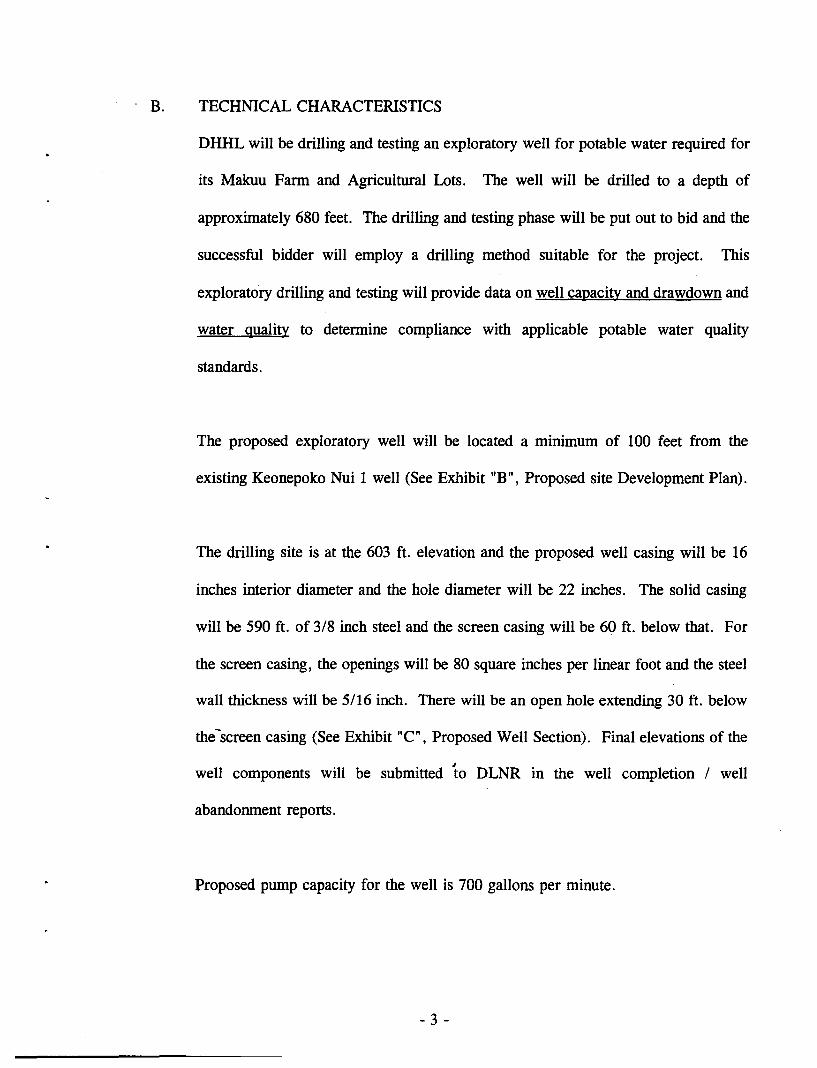
'B. TECHNICAL CHARACTERISTICS
DHHL will be drilling and testing an exploratory well for potable water required for
its Makuu Farm and Agricultural Lots. The well will be drilled to a depth of
approximately 680 feet. The drilling and testing phase will be put out to bid and the
successful bidder will employ a drilling method suitable for the project. This
exploratory drilling and testing will provide data on well capacity and drawdown and
water quality to determine compliance with applicable potable water quality
standards.
The proposed exploratory well will be located a minimum of 100 feet from the
existing Keonepoko Nui 1 well (See Exhibit "B", Proposed site Development Plan).
The drilling site is at the 603 ft. elevation and the proposed well casing will be 16
inches interior diameter and the hole diameter will be 22 inches. The solid casing
will be 590 ft. of 3/8 inch steel and the screen casing will be 60 ft. below that. For
the screen casing, the openings will be 80 square inches per linear foot and the steel
wall thickness will be 5/16 inch. There will be an open hole extending 30 ft. below
the-screen casing (See Exhibit "C", Proposed Well Section). Final elevations of the
well components will be submitted to DLNR in the well completion / well
abandonment reports.
Proposed pump capacity for the well is 700 gallons per minute.
- 3 -
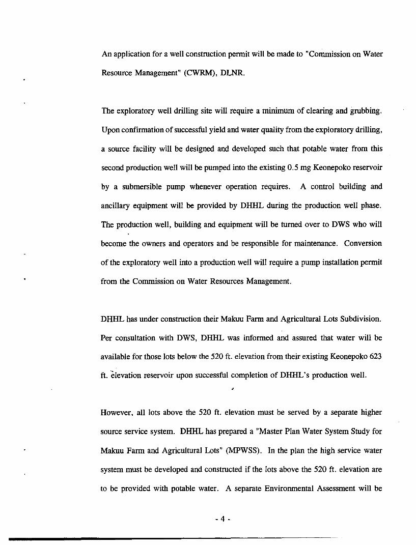
An application for a well construction permit will be made to "Commission on Water
Resource Management" (CWRM), DLNR.
The exploratory well drilling site will require a minimum of clearing and grubbing.
Upon confirmation of successful yield and water quality from the exploratory drilling,
a source facility will be designed and developed such that potable water from this
second production well will be pumped into the existing 0.5 mg Keonepoko reservoir
by a submersible pump whenever operation requires. A control building and
ancillary equipment will be provided by DHHL during the production well phase.
The production well, building and equipment will be turned over to DWS who will
become the owners and operators and be responsible for maintenance. Conversion
of the exploratory well into a production well will require a pump installation permit
from the Commission on Water Resources Management.
DHHL has under construction their Makuu Farm and Agricultural Lots Subdivision.
Per consultation with DWS, DHHL was informed and assured that water will be
available for those lots below the 520 ft. elevation from their existing Keonepoko 623
ft. elevation reservoir upon successful completion of DHHL's production well.
However, all lots above the 520 ft. elevation must be served by a separate higher
source service system. DHHL has prepared a "Master Plan Water System Study for
Makuu Farm and Agricultural Lots" (MPWSS). In the plan the high service water
system must be developed and constructed if the lots above the 520 ft. elevation are
to be provided with potable water. A separate Environmental Assessment will be
- 4 -
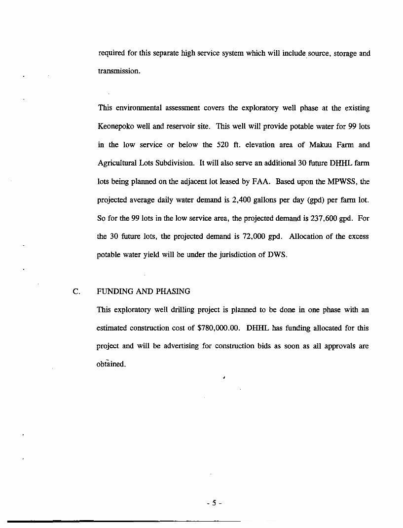
required for this separate high service system which will include source, storage and
transmission.
This environmental assessment covers the exploratory well phase at the existing
Keonepoko well and reservoir site. This well will provide potable water for 99 lots
in the low service or below the 520 ft. elevation area of Makuu Farm and
Agricultural Lots Subdivision. It will also serve an additional 30 future DHHL farm
lots being planned on the adjacent lot leased by FAA. Based upon the MPWSS, the
projected average daily water demand is 2,400 gallons per day (gpd) per farm lot.
So for the 99 lots in the low service area, the projected demand is 237,600 gpd. For
the 30 future lots, the projected demand is 72,000 gpd. Allocation of the excess
potable water yield will be under the jurisdiction of DWS.
C. FUNDING AND PHASING
This exploratory well drilling project is planned to be done in one phase with an
estimated construction cost of $780,000.00. DHHL has funding allocated for this
project and will be advertising for construction bids as soon as all approvals are
obtained.
;
- 5 -
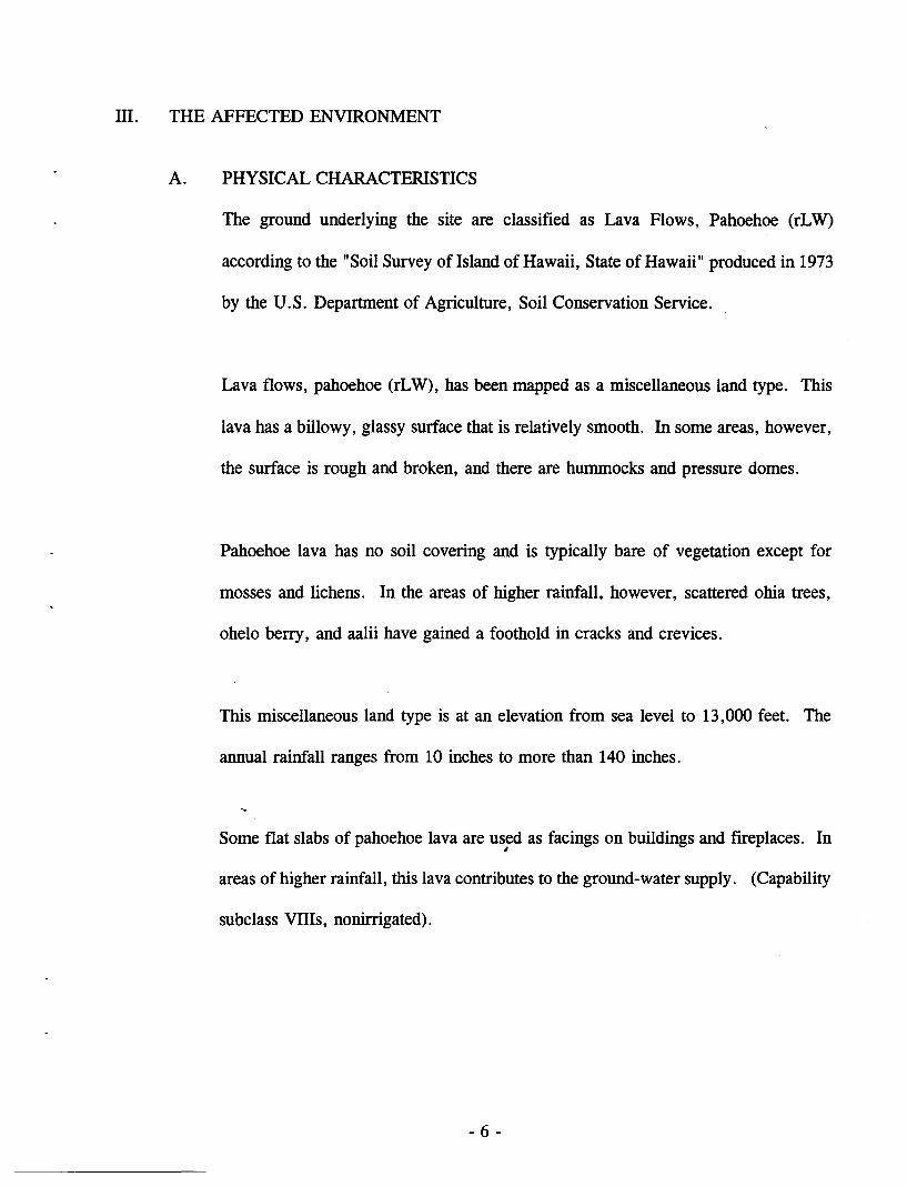
III. THE AFFECTED ENVIRONMENT
A. PHYSICAL CHARACTERISTICS
The ground underlying the site are classified as Lava Flows, Pahoehoe (rLW)
according to the "Soil Survey of Island of Hawaii, State of Hawaii" produced in 1973
by the U.S. Department of Agriculture, Soil Conservation Service.
Lava flows, pahoehoe (rLW), has been mapped as a miscellaneous land type. This
lava has a billowy, glassy surface that is relatively smooth. In some areas, however,
the surface is rough and broken, and there are hummocks and pressure domes.
Pahoehoe lava has no soil covering and is typically bare of vegetation except for
mosses and lichens. In the areas of higher rainfall, however, scattered ohia trees,
ohelo berry, and aalii have gained a foothold in cracks and crevices.
This miscellaneous land type is at an elevation from sea level to 13,000 feet. The
annual rainfall ranges from 10 inches to more than 140 inches.
Some flat slabs of pahoehoe lava are used as facings on buildings and fireplaces. In I
areas of higher rainfall, this lava contributes to the ground-water supply. (Capability
subclass VilIs, nonirrigated).
- 6 -
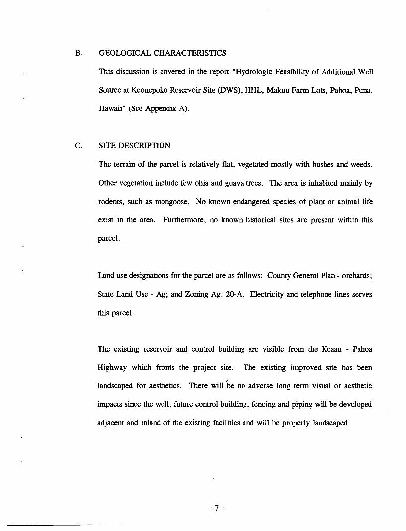
B. GEOLOGICAL CHARACTERISTICS
This discussion is covered in the report "Hydrologic Feasibility of Additional Well
Source at Keonepoko Reservoir Site (DWS), HHL, Makuu Farm Lots, Pahoa, Puna,
Hawaii" (See Appendix A).
C. SITE DESCRIPTION
The terrain of the parcel is relatively flat, vegetated mostly with bushes and weeds.
Other vegetation include few ohia and guava trees. The area is inhabited mainly by
rodents, such as mongoose. No known endangered species of plant or animal life
exist in the area. Furthennore, no known historical sites are present within this
parcel.
Land use designations for the parcel are as follows: County General Plan - orchards;
State Land Use - Ag; and Zoning Ag. 20-A. Electricity and telephone lines serves
this parcel.
The existing reservoir and control building are visible from the Keaau - Pahoa
Highway which fronts the project site. The existing improved site has been
i
landscaped for aesthetics. There will be no adverse long tenn visual or aesthetic
impacts since the well, future control building, fencing and piping will be developed
adjacent and inland of the existing facilities and will be properly landscaped.
- 7 -
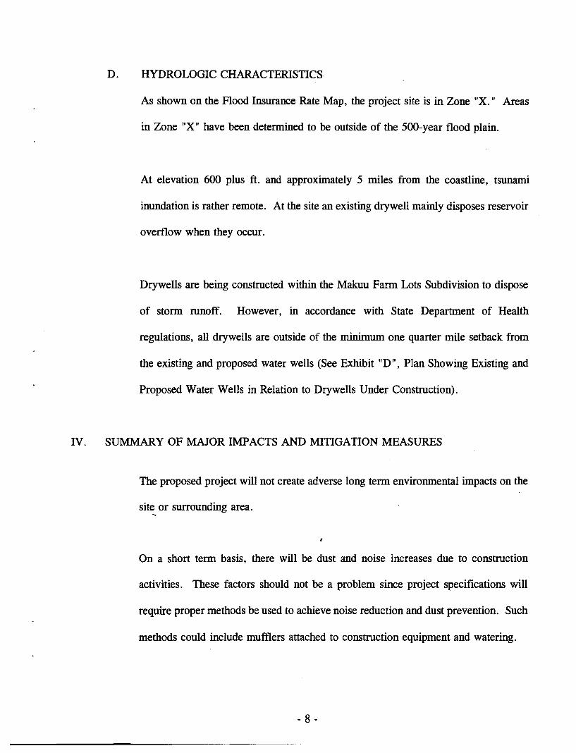
D. HYDROLOGIC CHARACTERISTICS
As shown on the Flood Insurance Rate Map, the project site is in Zone "X." Areas
in Zone "X" have been determined to be outside of the 500-year flood plain.
At elevation 600 plus ft. and approximately 5 miles from the coastline, tsunami
inundation is rather remote. At the site an existing drywell mainly disposes reservoir
overflow when they occur.
Drywells are being constructed within the Makuu Farm Lots Subdivision to dispose
of storm runoff. However, in accordance with State Department of Health
regulations, all drywells are outside of the minimum one quarter mile setback from
the existing and proposed water wells (See Exhibit "D", Plan Showing Existing and
Proposed Water Wells in Relation to Drywells Under Construction).
IV. SUMMARY OF MAJOR IMPACTS AND MITIGATION MEASURES
The proposed project will not create adverse long term environmental impacts on the
site or surrounding area. ~
On a short term basis, there will be dust and noise increases due to construction
activities. These factors should not be a problem since project specifications will
require proper methods be used to achieve noise reduction and dust prevention. Such
methods could include mufflers attached to construction equipment and watering.
- 8 -
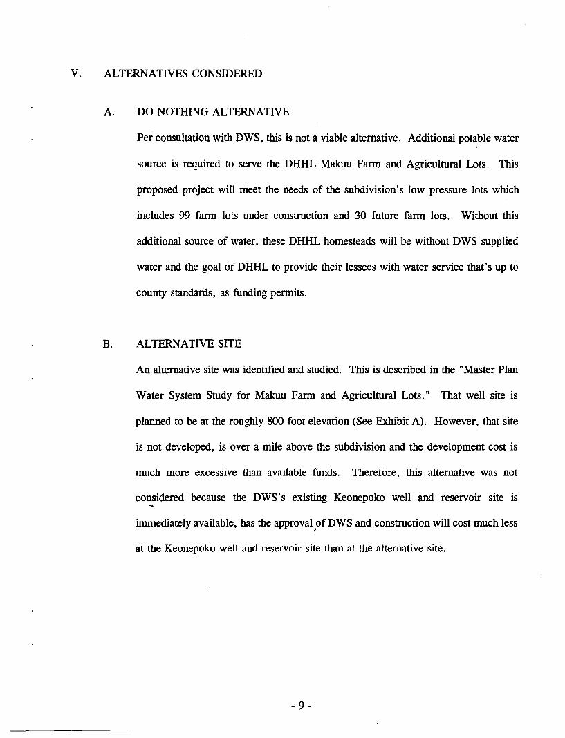
V. ALTERNATIVES CONSIDERED
A. DO NOTHING ALTERNATIVE
Per consultation with DWS, this is not a viable alternative. Additional potable water
source is required to serve the DHHL Makuu Farm and Agricultural Lots. This
proposed project will meet the needs of the subdivision's low pressure lots which
includes 99 farm lots under construction and 30 future farm lots. Without this
additional source of water, these DHHL homesteads will be without DWS supplied
water and the goal of DHHL to provide their lessees with water service that's up to
county standards, as funding permits.
B. ALTERNATIVE SITE
An alternative site was identified and studied. This is described in the "Master Plan
Water System Study for Makuu Farm and Agricultural Lots." That well site is
planned to be at the roughly 800-foot elevation (See Exhibit A). However, that site
is not developed, is over a mile above the subdivision and the development cost is
much more excessive than available funds. Therefore, this alternative was not
considered because the DWS's existing Keonepoko well and reservoir site is ...
immediately available, has the approval of DWS and construction will cost much less ~
at the Keonepoko well and reservoir site than at the alternative site.
- 9 -
VI. DETERMINATION, FINDINGS AND REASONS SUPPORTING DETERMINATION
After completing an assessment of the potential environmental effects of the proposed
exploratory well drilling and consulting with other governmental agencies, it has been
determined that an Environmental Impact Statement (EIS) is not required. Therefore, the
Department anticipates the issuance of a Negative Declaration.
1. The proposed action consists primarily of drilling and testing an exploratory well to
determine well capacity, drawdown and water quality during this phase.
2. There will be no permanent degradation of existing ambient air and noise quality
levels. During the actual drilling, there will be minor air pollution and noise
resulting from the actual drilling, but these will not be permanent and will be within
the State Department of Health Air Quality Standards.
3. There are no known endangered species of animal or plants within the project drilling
site.
4. There are no natural, historic, or archaeological sites within the project drilling site. I
5. The project is consistent with DWS plans for water source development. Exploratory
well development by the Department is a permitted use by the State and County
zoning designations.
- 10 -
6. This project, if successful as planned, will provide potable water for the low pressure
service system of DHHL's Makuu Farm and Agricultural Lots Subdivision which is
under construction. Any adverse impacts of the proposed project have been
determined to be insignificant. The applicant will comply with applicable statutes,
ordinances, and rules of the Federal, State, and county governments during the
implementation of the actual drilling and testing phase.
- 11 -

-VII. LIST OF AGENCIES CONSULTED IN THE PREPARATION OF THIS
ENVIRONMENTAL ASSESSMENT
Commission on Water Resource Management Department of Land and Natural Resources State of Hawaii
Department of Water Supply County of Hawaii
Planning Department County of Hawaii
- 12 -
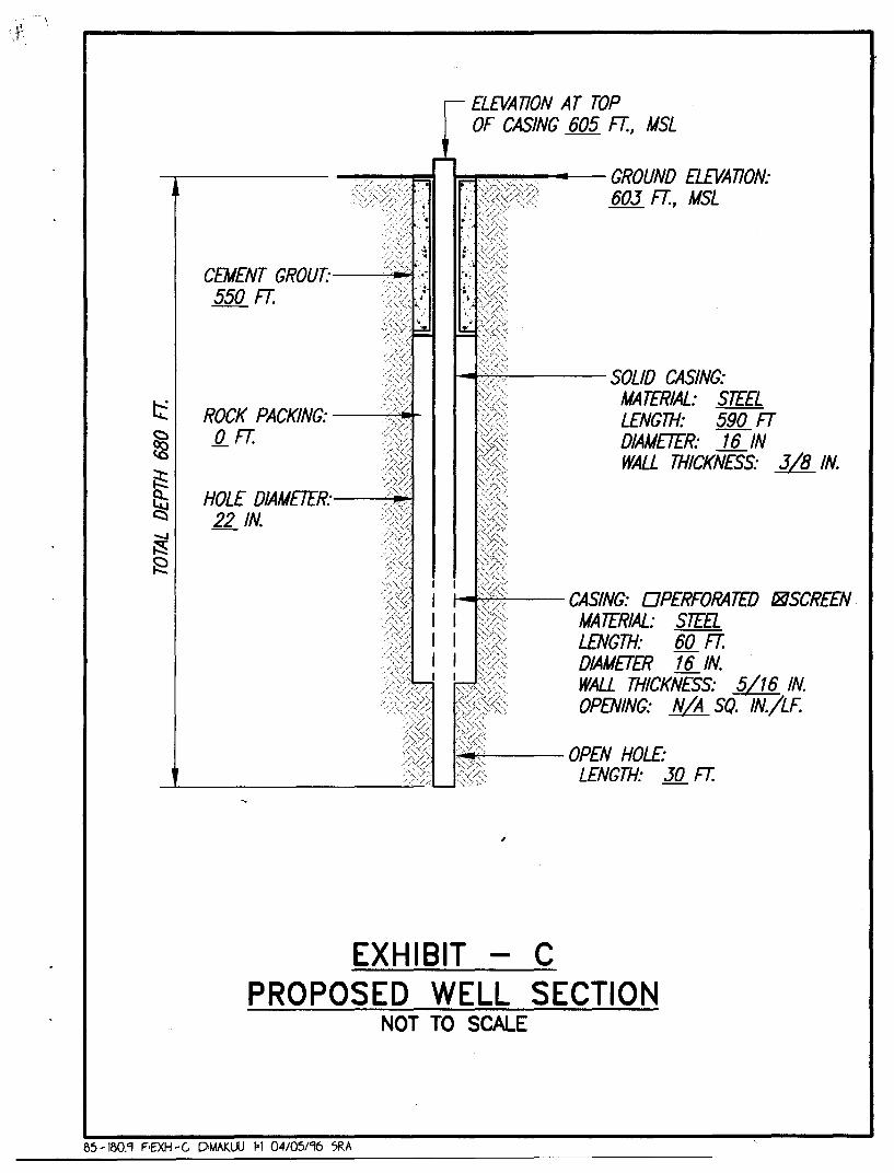
CEMENT GROUT:-----'-I-..t 550 FT.
ROCK PACKING: -----'-".....rQFT.
HOLE DIAMETER:----"-I .... 22 IN.
ELEVATION AT TOP OF CASING 605 FT., MSL
~~~..-..-- GROUND ELEVATION: 603 FT., MSL
~~--- SOLID CASING: MATERIAL: STEEL LENGTH: 590 FT DIAMETER: 16 IN WALL THICKNESS: 318 IN.
I--.:~-- CASING: OPERFORATED I8SCREEN
.~;>:··3~~ MA TERIAL: STEEL LENGTH: 60 FT. DIAMETER 16 IN. WALL THICKNESS: 5116 IN. OPENING: NIA SQ. IN./LF.
I~~-- OPEN HOLE: S'(;<,: LENGTH: 30 FT.
~---------"-'-/"'---" "',,
EXHIBIT - C PROPOSED WELL SECTION
NOT TO SCALE
1'>5 -100,9 F-EXH - (, D'MAKUU 1·1 04/05/96 7RA
APPENDIX A
" HYDROLOGIC FEASffiILITY OF ADDITIONAL WELL SOURCE AT KEONEPOKO RESERVOIR SITE (DWS),
HHL MAKUU FARM LOTS, PAHOA, PUNA, HAWAII, " BY WATER RESOURCE ASSOCIATES.
Hydrologic Feasibility of Additional Well Source at Keonepoko Reservoir Site (DWS), HHL Makuu Farm Lots, Pahoa, Puna, Hawaii
INTRODUCTION
Hawaiian Home Lands needs to develop a source of water supply for its
Makuu Fannlot Subdivision located north of Pahoa town. One alternative being
considered is to drill a well at the Keonepoko Reservoir Site, which belongs to the
Hawaii County Department of Water Supply (see Figure 1). The site is located
alongside Highway 130 at an approximate elevation of 605 feet, just south of the
fann lots.
An existing deep well, Keonepoko Nui 1, -is located within the reservoir site
and it has an installed pump capacity of 700 gpm. This report discusses the
hydrologic feasibility of developing an additional well source within this reservoir
site to serve the water needs of the Makuu Fannlots Subdivision.
PAHOA AQUIFER SYSTEM
Boundaries. The proposed project is located within the Pahoa Aquifer
System in an area of high rainfall. The aquifer system, which is a part of the 564
square-mile Kilauea Hydrologic Sector, embraces a wedge-shaped area of 222 square
miles extending from Kilauea Crater eastward to the ocean between the Kilauea East
Rift Zone and the Volcano-Keaau Highway (see Figure 2).
Geology. The Pahoa Aquifer System is Icomprised chiefly of basaltic flank
flows of the Puna volcanic series. These basaltic flows are geologically young (30
to 10,000 years at the surface), relatively unweathered, highly permeable, and
typically yield water readily to wells. The lavas are dike-free, except in the Kilauea
East Rift zone.
Due to their young age and lack of weathering, the permeable basalts readily
absorb rainfall and streams and streamt10ws are essentially nonexistent.
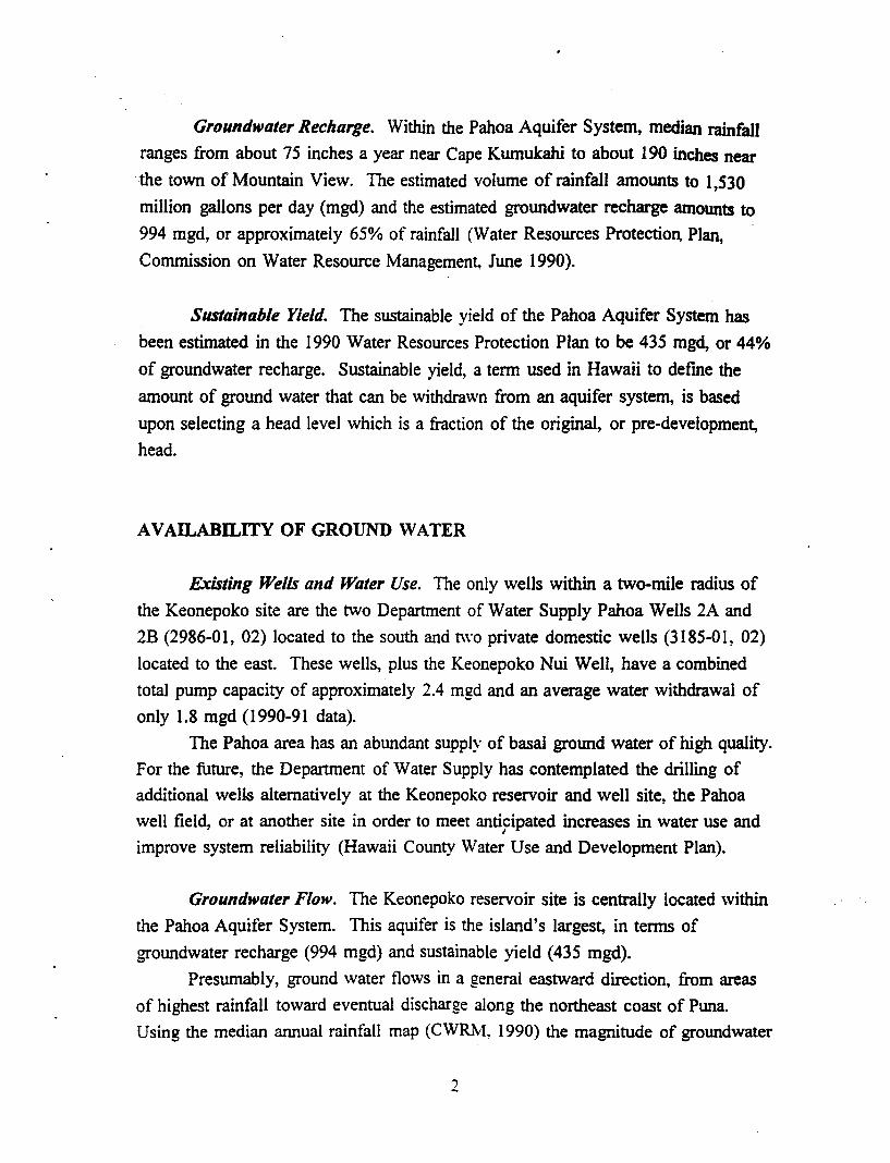
Groundwater Recharge. Within the Pahoa Aquifer System, median rainfall
ranges from about 75 inches a year near Cape Kumukahi to about 190 inches near
. the town of Mountain View. The estimated volume of rainfall amounts to 1,530
million gallons per day (mgd) and the estimated groundwater recharge amounts to
994 mgd, or approximately 65% of rainfall (Water Resources Protection, Plan,
Commission on Water Resource Management, June 1990).
Sustainable Yield. The sustainable yield of the Pahoa Aquifer System has
been estimated in the 1990 Water Resources Protection Plan to be 435 mgd, or 44%
of groundwater recharge. Sustainable yield, a tenn used in Hawaii to defme the
amount of ground water that can be withdrawn from an aquifer system, is based
upon selecting a head level which is a fraction of the original, or pre-development,
head.
AVAILABll..ITY OF GROUND WATER
Existing Wells and Water Use. The only wells within a two-mile radius of
the Keonepoko site are the two Department of Water Supply Pahoa Wells 2A and
2B (2986-01, 02) located to the south and two private domestic wells (3185-01, 02)
located to the east. These wells, plus the Keonepoko Nui Well, have a combined
total pump capacity of approximately 2.4 mgd and an average water withdrawal of
only 1.8 mgd (1990-91 data).
The Pahoa area has an abundant supply of basal ground water of high quality.
For the future, the Department of Water Supply has contemplated the drilling of
additional wells alternatively at the Keonepoko reservoir and well site, the Pahoa
well field, or at another site in order to meet anticipated increases in water use and •
improve system reliability (Hawaii County Water Use and Development Plan).
Groundwater Flow. The Keonepoko reservoir site is centrally located within
the Pahoa Aquifer System. This aquifer is the island's largest, in tenns of
groundwater recharge (994 mgd) and sustainable yield (435 mgd).
Presumably, ground water flows in a general eastward direction, from areas
of highest rainfall toward eventual discharge along the northeast coast of Puna.
Using the median annual rainfall map (CWRM. 1990) the magnitude of groundwater
2
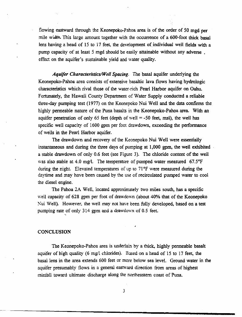
flowing eastward through the Keonepoko-Pahoa area is of the order of 50 mgd per
mile width. This large amount together with the occurrence of a 600-foot thick basal
lens having a head of 15 to 17 feet, the development of individual well fields with a
pump capacity of at least 5 mgd should be easily attainable without any adverse .
effect on the aquifer's sustainable yield and water quality.
Aquifer CllaracteristicslWell Spacing. The basal aquifer underlying the
Keonepoko-Pahoa area consists of extensive basaltic lava flows having hydrologic
characteristics which rival those of the water-rich Pearl Harbor aquifer on Oahu.
Fortunately, the Hawaii County Department of Water Supply conducted a reliable
three-day pumping test (1977) on the Keonepoko Nui Well and the data confmns the
highly permeable nature of the Puna basalts in the Keonepoko-Pahoa area. With an
aquifer penetration of only 65 feet (depth of well = -50 feet, msl), the well has
specific well capacity of 1600 gpm per foot drawdown, exceeding the performance
of wells in the Pearl Harbor aquifer.
The drawdown and recovery of the Keonepoko Nui Well were essentially
instantaneous and during the three days of pumping at 1,000 gpm, the well exhibited
a stable drawdown of only 0.6 feet (see Figure 3). The chloride content of the well
was also stable at 4.0 mg/I. The temperature of pumped water measured 67.5°F
during the night. Elevated temperatures of up to 71°F were measured during the da)time and may have been caused by the use of recirculated pumped water to cool
the diesel engine.
The Pahoa 2A Well, located approximately two miles south, has a specific
well capacity of 628 gpm per foot of drawdo\\n (about 40% that of the Keonepoko
Nui Well). However, the well may not have been fully developed, based on a test
pumping rate of only 314 gpm and a drawdo\\n of 0.5 feet.
CONCLUSION
The Keonepoko-Pahoa area is underlain by a thick, highly permeable basalt
aquifer of high quality (6 mg/l chlorides). Based on a head of 15 to 17 feet, the
basal lens in the area extends 600 feet or more below sea level. Ground water in the
aquifer presumably flows in a general eastward direction trom areas of highest
rainfall toward ultimate discharge along the northeastern coast of Puna.
3
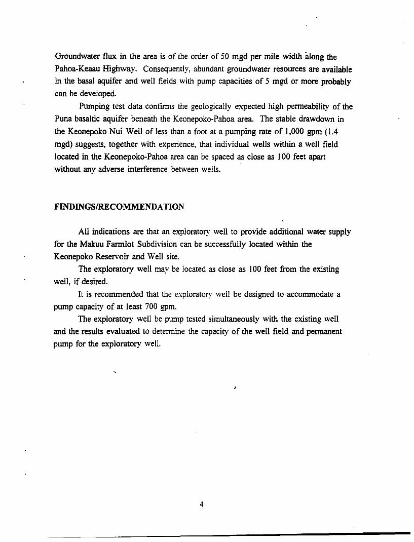
Groundwater flux in the area is of the order of 50 mgd per mile width along the
Pahoa-Keaau Highway. Consequently, abundant groundwater resources are available
in the basal aquifer and well fields with pump capacities of 5 mgd or more probably
can be developed.
Pumping test data confirms the geologically expected high permeability of the
Puna basaltic aquifer beneath the Keonepoko-Pahoa area. The stable drawdown in
the Keonepoko Nui Well of less than a foot at a pumping rate of 1,000 gpm (1.4
mgd) suggests, together with experience, that individual wells within a well field
located in the Keonepoko-Pahoa area can be spaced as close as 100 feet apart
without any adverse interference between wells.
FINDINGSIRECOMMENDA TION
All indications are that an exploratory well to provide additional water supply
for the Makuu Fannlot Subdh·ision can be successfully located within the
Keonepoko Reservoir and Well site.
The exploratory well may be located as close as 100 feet from the existing
well, if desired.
It is recommended that the exploratory well be designed to accommodate a
pump capacity of at least 700 gpm.
The exploratory well be pump tested simultaneously with the existing well
and the results evaluated to determine the capacity of the well field and permanent
pump for the exploratory well.
4

.• I
" ,
...... '.
, , ..
\~ 4~
Y/(2~ ,"-~_s_caJ_e _,_,m_ile .....
, , :~ ,'~
. ' I
I
, ,
~ ,/ ~ ( ~--------------------------------~ ; )
" i J otto.'''' ;!
LEGEND
• KEONEPOKO NUl WELL.1 .1i.1)..~,,)~.: .. t .~ "''' .. '/~' ~
,!
... \ '''L
• PAHOA OEEP WEU 2A & 28
• MUNICIPAL WATER SERVICE AREA Cl PROPOSEO WATER DEVELOPMENT AREA
(!} Source and Reservoir Oevefopment. @ Transmission Main Development
-. .: ~-"'" -.,' ... ,.1-
Figure 1. Pahoa Area
REGIONAL WATER DEVELOPMENT PLAN
(Modified after Fig. 1.9-1, Hawaii County Water Use and Development Plan, Review Craft. 2192
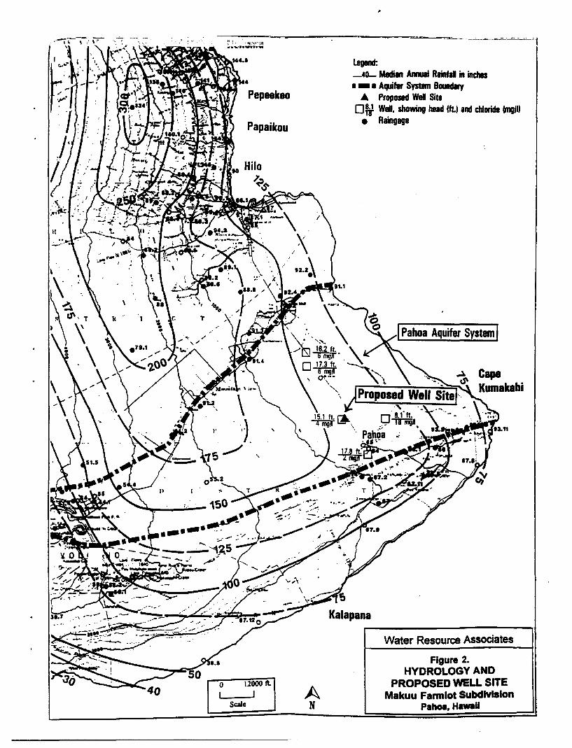
. ~-~~~~ .' I, ~ \ '" ~' ~t L, . ":r:'(irl'1l1 ..... "." .... ~ ...
Papaikou
o 12000 It I J
Scale A N
..
legend: _40- Median Annual Rainfall in inches • - • Aquifer Systn 80111d1ry
A Proposaci Well Site Oft Well, showing head 1ft.) and chloride fmglll
• Raingage
Kalapana
I Pahoa Aquifer System I
Water Resource Associates
Figure 2. HYDROLOGY AND
PROPOSED WELL SITE Makuu Fannlot Subdivision
Pahoa,HawaU
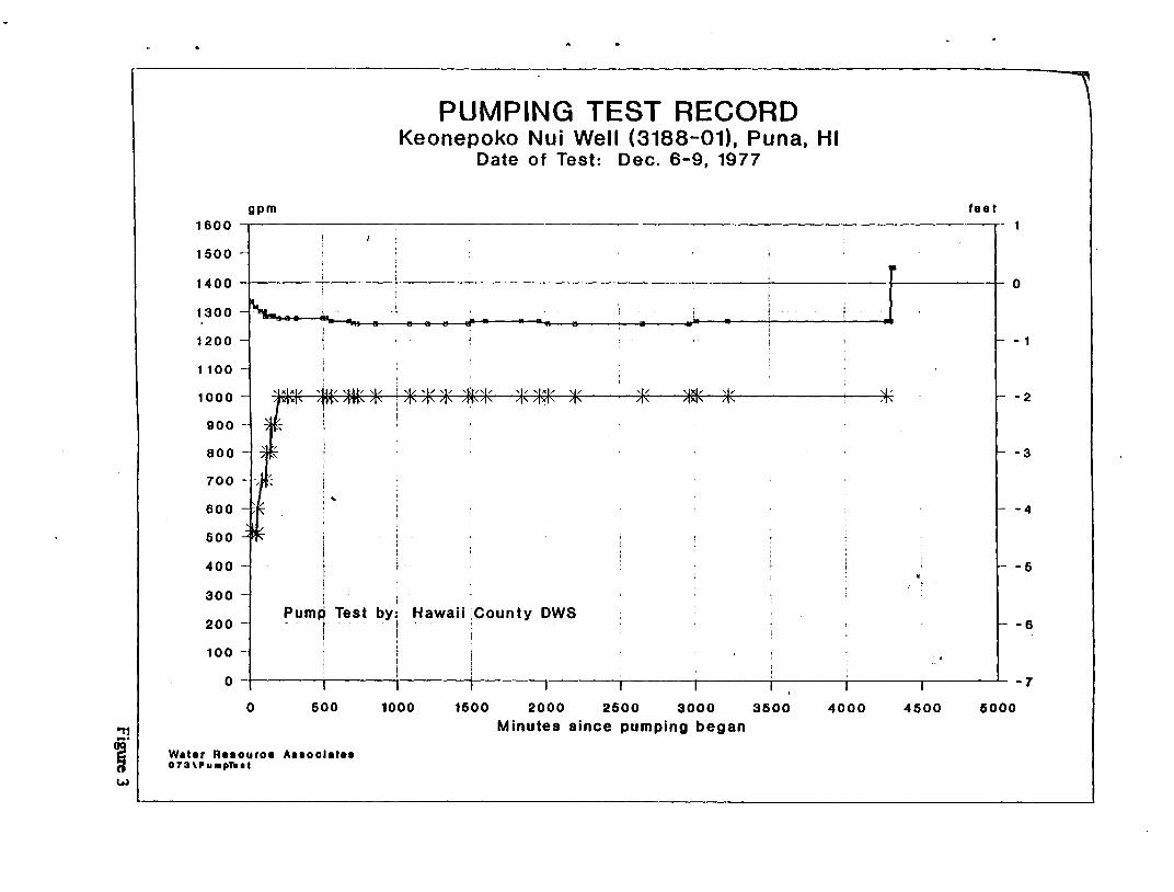
gpm 1600
1500
PUMPING TEST RECORD Keonepoko Nui Well (3188-01), Puna, HI
Date of Test: Dec. 6-9, 1977
fee t
1400 ---------------------~----------~ 0
1300
1200 - 1
1100
1000 , /
-2
900 -
800 -3
-4
400 -5
300 j f
-6 Pump Test by; Hawaii County DWS . I . j
I I 200
100 -
o ~------,-------+_------T_------._------._------r_------r_------r_------r_------~ -7
o 500
Wat.r R.aouroe Aaaoolatea 073\PuIRpT ...
1000 1500 2000 2500 3000 3500 4000 4500 5000 Minutes since pumping began
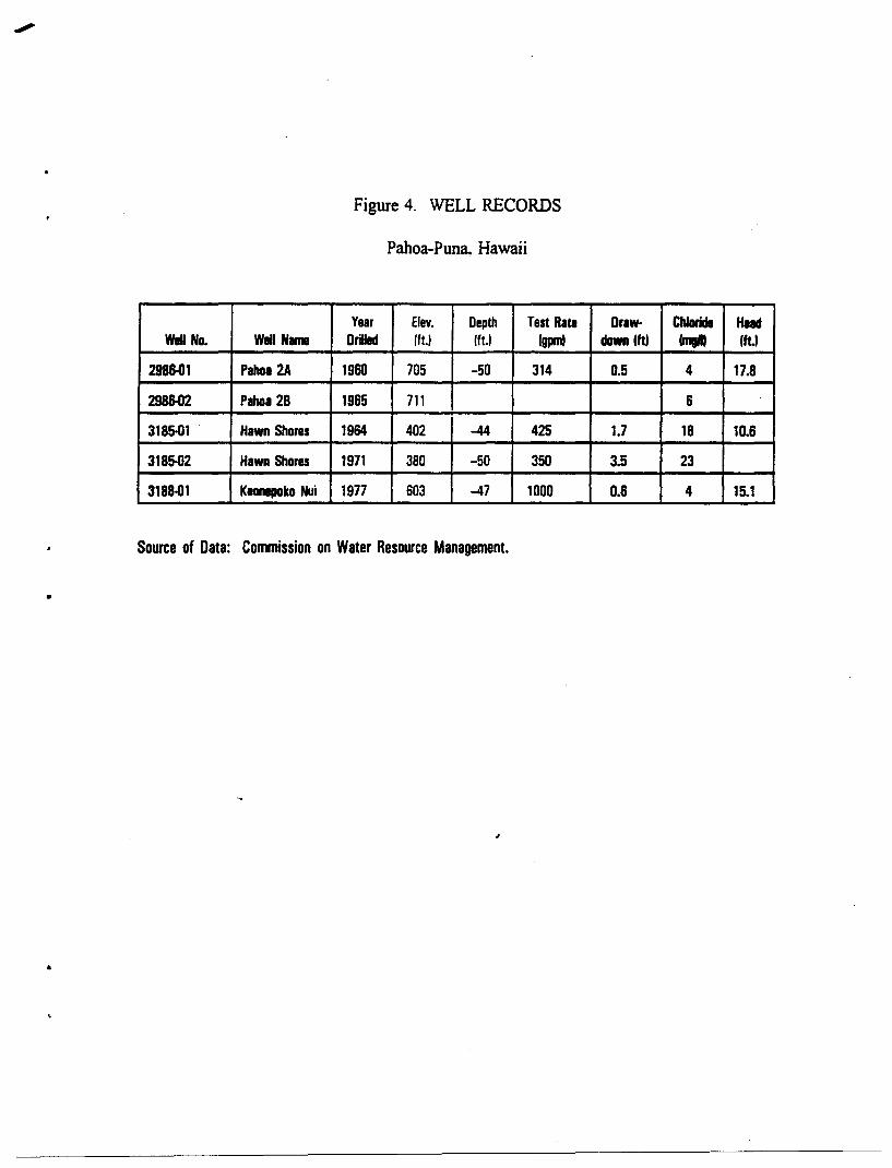
Figure 4. WELL RECORDS
Pahoa-Puna. Hawaii
Year Etev. Depth Test Rata Draw· Chloride Head Wall No. Wall Name DriUed 1ft.) 1ft.) Igpml dawn Iftl Imgft) Iftl
298&01 Pahoa 2A 1960 705 -50 314 0.5 4 17.8
298&02 Pahoa 28 1965 711 6
3185-01 . Hawn Shares 1964 402 -44 425 1.7 18 10.6
3185-02 Hawn Shorn 1971 380 -50 350 3.5 23
3188-01 Kaanepako Nui 1977 603 -47 1000 0.6 4 15.1
Source of Data: Commission on Water Resource Management.
•