Embed Size (px)
Citation preview
BASIC DESIGN STUDY REPORT ON
THE PROJECT FOR
RURAL ELECTRIFICATION IN
NORTHERN LUZON IN
REPUBLIC OF THE PHILIPPINES
June 2007 JAPAN INTERNATIONAL COOPERATION AGENCY
NIPPON KOEI CO., LTD.
NEWJEC Inc.
Department of Energy Republic of the Philippines

PREFACE
In response to a request from the Government of the Republic of the Philippines,
the Government of Japan decided to conduct a basic design study on the Project for
Rural Electrification in Northern Luzon and entrusted the study to the Japan
International Cooperation Agency (JICA).
JICA sent to the Philippines a study team from November 2 to December 13,
2005.
The team held discussions with the officials concerned of the Government of the
Philippines, and conducted a field study at the study area. After the team returned to
Japan, further studies were made. Then, a mission was sent to the Philippines in
order to discuss a draft basic design, and as this result, the present report was
finalized.
I hope that this report will contribute to the promotion of the project and to the
enhancement of friendly relations between our two countries.
I wish to express my sincere appreciation to the officials concerned of the
Government of the Republic of the Philippines for their close cooperation extended to
the teams.
June 2007
Masafumi KUROKI
Vice-President
Japan International Cooperation Agency

June, 2007
Letter of Transmittal
We are pleased to submit to you the basic design study report on the Project for
Rural Electrification in Northern Luzon in the Republic of the Philippines.
This study was conducted by the consortium of Nippon Koei Co., Ltd., and
Newjec Inc. under a contract to JICA, during the period from October, 2006 to July
2007. In conducting the study, we have examined the feasibility and rationale of the
project with due consideration to the present situation of the Philippines and
formulated the most appropriate basic design for the project under Japan’s grant aid
scheme.
Finally, we hope that this report will contribute to further promotion of the
project.
Very truly yours,
Michio HASEGAWA
Chief Consultant, Basic design study team on The Project for Rural Electrification in Northern Luzon The consortium of Nippon Koei Co., Ltd., and Newjec Inc.


i
Basic Design Report on
The Project for Rural Electrification in Northern Luzon In
the Republic of the Philippines
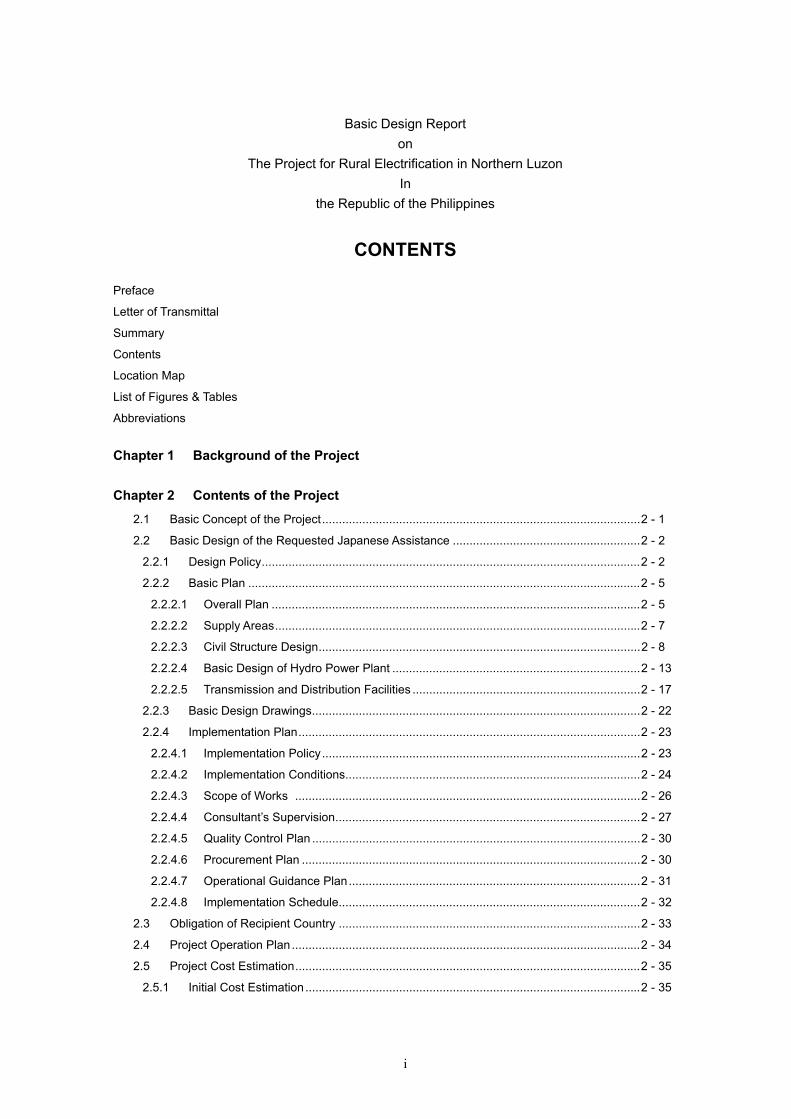
CONTENTS
Preface
Letter of Transmittal
Summary
Contents
Location Map
List of Figures & Tables
Abbreviations
Chapter 1 Background of the Project
Chapter 2 Contents of the Project
2.1 Basic Concept of the Project...............................................................................................2 - 1
2.2 Basic Design of the Requested Japanese Assistance ........................................................2 - 2
2.2.1 Design Policy.................................................................................................................2 - 2
2.2.2 Basic Plan .....................................................................................................................2 - 5
2.2.2.1 Overall Plan ..............................................................................................................2 - 5
2.2.2.2 Supply Areas.............................................................................................................2 - 7
2.2.2.3 Civil Structure Design................................................................................................2 - 8
2.2.2.4 Basic Design of Hydro Power Plant ..........................................................................2 - 13
2.2.2.5 Transmission and Distribution Facilities ....................................................................2 - 17
2.2.3 Basic Design Drawings..................................................................................................2 - 22
2.2.4 Implementation Plan......................................................................................................2 - 23
2.2.4.1 Implementation Policy...............................................................................................2 - 23
2.2.4.2 Implementation Conditions........................................................................................2 - 24
2.2.4.3 Scope of Works .......................................................................................................2 - 26
2.2.4.4 Consultant’s Supervision...........................................................................................2 - 27
2.2.4.5 Quality Control Plan ..................................................................................................2 - 30
2.2.4.6 Procurement Plan .....................................................................................................2 - 30
2.2.4.7 Operational Guidance Plan.......................................................................................2 - 31
2.2.4.8 Implementation Schedule..........................................................................................2 - 32
2.3 Obligation of Recipient Country ..........................................................................................2 - 33
2.4 Project Operation Plan ........................................................................................................2 - 34
2.5 Project Cost Estimation.......................................................................................................2 - 35
2.5.1 Initial Cost Estimation ....................................................................................................2 - 35

ii
2.5.2 Operation and Maintenance Cost ................................................................................. 2 - 36
Chapter 3 Project Evaluation and Recommendations
3.1 Project Effects..................................................................................................................... 3 - 1
3.2 Recommendations.............................................................................................................. 3 - 2
3.2.1 Recommendations ........................................................................................................ 3 - 2
3.2.2 Cooperation with Technical Assistance ......................................................................... 3 - 2
Drawings (Contents is attached at inner cover)
Appendixes
1. Member List of the Study Team
2. Study Schedule
3. List of Parties Concerned in the Recipient Country
4. Minutes of Discussions (site survey)
Technical Note (site survey)
5. Minutes of Discussion (Explanation of the Draft Report)
6. Comprehensive Evaluation of the 12 sites
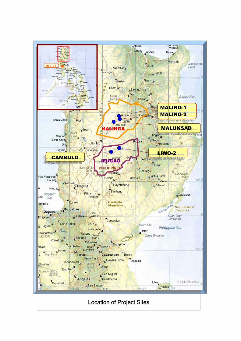
MANILA
KALINGA
IFUGAO
Location of Project Sites
MALING-1 MALING-2
MALUKSAD
LIWO-2 CAMBULO
List of Tables
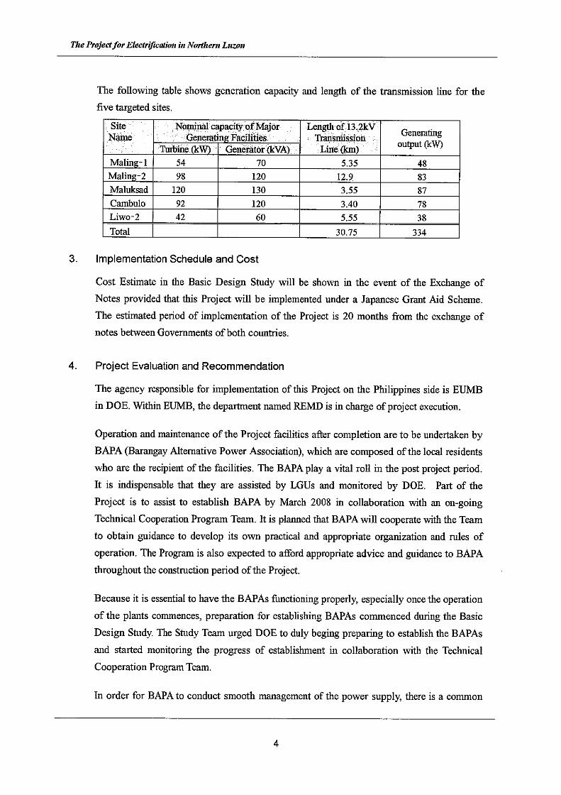
Table 2.1-1 Requested and Selected Sites ................................................................................ 2 - 2
Table 2.2-1 Power Demand of Electrified Barangay................................................................... 2 - 5
Table 2.2-2 Assumed Power Demand per Household................................................................ 2 - 5
Table 2.2-3 Supply Barangay to be Planned in This Project ...................................................... 2 - 7
Table 2.2-4 Channel Type for Headrace..................................................................................... 2 - 9
Table 2.2-5 Features of 5 Micro Hydropower Stations................................................................ 2 - 12
Table 2.2-6 Basic Design of Generating Equipment................................................................... 2 - 16
Table 2.2-7 Power Supplying System in the Project................................................................... 2 - 18
Table 2.2-8 Allowable Voltage Drop Ratio .................................................................................. 2 - 19
Table 2.2-9 Length of Transmission Line for each Site............................................................... 2 - 19
Table 2.2-10 Total Length of Conductors for Each Site ................................................................ 2 - 20
Table 2.2-11 Length of Low Voltage Distribution Line for each Site ............................................. 2 - 20
Table 2.2-12 Embedding Depth of the Poles................................................................................ 2 - 20
Table 2.2-13 Specification of Pole-mounted Transformer............................................................. 2 - 21
Table 2.2-14 Cross Arms and Fittings for Pole ............................................................................. 2 - 21
Table 2.2-15 List of Basic Design Drawings ................................................................................. 2 - 22
Table 2.2-16 Scope of Works ....................................................................................................... 2 - 27
Table 2.2-17 Member for Detailed design .................................................................................... 2 - 28
Table 2.2-18 Member for Construction Supervision ..................................................................... 2 - 29
Table 2.2-19 Quality Control Plan ................................................................................................ 2 - 30
Table 2.2-20 Procurement Plan.................................................................................................... 2 - 30
Table 2.2-21 Implementation Schedule ........................................................................................ 2 - 32
Table 2.5-1 Items for Major Expenditure .................................................................................... 2 - 36
Table 2.5-2 Necessary Staff for Management for BAPA............................................................. 2 - 37
Table 2.5-3 Required Personnel for Management of BAPA (day)............................................... 2 - 37
Table 2.5-4 Estimated Labor Cost (Month)................................................................................. 2 - 38
List of Figures
Figure 2.2-1 Selection of Turbine................................................................................................. 2 - 13
Note: All tables and figures that are not mentioned their sources were prepared by the Study Team.

Abbreviations ABEP Accelerated Barangay Electrification Program ANECs Affiliated Non-Conventional Energy Center BAPA Barangay Alternative Power Association BHN Basic Human Needs DOE Department of Energy EA Electric Agency EC Electric Cooperative ER Program Expanded Rural Electrification Program IEC International Electro-technical Commission ISO International Organization For Standardization JICA Japan International Cooperation Agency JEM Japan Electric Machine Industry JIS Japan Industry Standard LGU Local Government Units NEA National Electric Administration ODA Official Development Assistance PEC Philippine Electric Code PMO Project Management Office REMD Renewable Energy Management Division SI The International System of Units WB World Bank
Units
length mm : Millimeters cm : Centimeters (10.0 mm ) m : Meters (100.0 cm) km : Kilometers (1,000.0 m) Area m2 : Square-meters (1.0 m x 1.0 m) km2 : Square-kilometers (1.0 km x 1.0 km) Volume m3 : Cubic-meters (1.0 m x 1.0 m x 1.0 m) Time sec. : Seconds Currency US$ : United State Dollars PhP Philippine Pesos JPY Japanese Yen Electricity kV : Kilo volts (1,000 V) kA Kilo-amperes W : Watts (active power) (J/s: Joule/second) VA Volt-amperes kW : Kilo watts (103 W) kVA Kilo volt-amperes MW Mega watts (106 W) MVA : Mega volt-amperes (106 VA)


Chapter 1 Background of the Project
1 - 1
CHAPTER 1 Background of the Project
The Philippines, with a land area of 299,400km2, about 80% that of Japan, is an archipelago
nation comprised of more than 7,100 islands. Owing to such geographic disadvantage, the
electrification rate currently stands at around 70%, 20 million out of 83 million people have no
access to electricity.
Rural electrification has been one of the priority policies of the Philippine government as a means
of improving the standard of living in remote agricultural villages and to reduce poverty by
generating income sources, targeting “100% electrification of villages by 2008” and “90%
electrification of households by 2017”.
As most of these un-electrified villages are scattered in mountainous areas or on remote islands,
electrification by extending the power grid is extremely difficult. Consequently, renewable
energy such as small or micro hydro-power and photovoltaic generation has been individually
developed in the past. In the future, 70% of rural electrifications are planned to be covered by
grid line extension while 30% will be by renewable energy sources.
Northern Luzon, which contains the project sites, is located in mountainous and sparsely
populated regions where more than 500 villages or 60,000 households are still un-electrified. The
DOE has been developing micro-hydro power stations; however, too few villages have been
electrified so far and those that have experience chronic problems of frequent malfunctions of the
equipment. These are caused by low quality equipment and improper operation and maintenance
services due to shortage of human or monetary resources.
The Japanese Government dispatched long term experts in 2001 to 2004, who selected potential
candidate sites for micro-hydro power stations and conducted technical transfer services such as
for project site selection/formulation and for operation and maintenance procedures. Since 2004
they have been rendering technical assistance under the “Rural Electrification Project” with the
aim of establishing a tariff system for electricity generated by renewable energy development. In
2003, “The Study of Micro-Hydropower Development for Un-energized Barangays in Northern
Luzon” was conducted by the JICA Manila office in which 50 potential sites were reconnoitered.
This list of sites was eventually culled to 20 through a screening process that took into
consideration hydro-power potential, power demand, ease of operation, and maintenance and site
access.

The Project for Rural Electrification in Northern Luzon
1 - 2
The Government of the Philippines intended to execute all of the proposed projects on its own
but was unable to because of financial difficulties. It therefore applied for Japanese Grant Aid
to execute 14 micro-hydro power stations from among the foregoing 20 candidate sites in
coordination with the above-mentioned technical assistance by JICA experts.

Chapter 2 Contents of the Project
2 - 1
Chapter 2 Contents of the Project
2.1 Basic Concept of the Project
(1) Overall Goal and Project Objectives
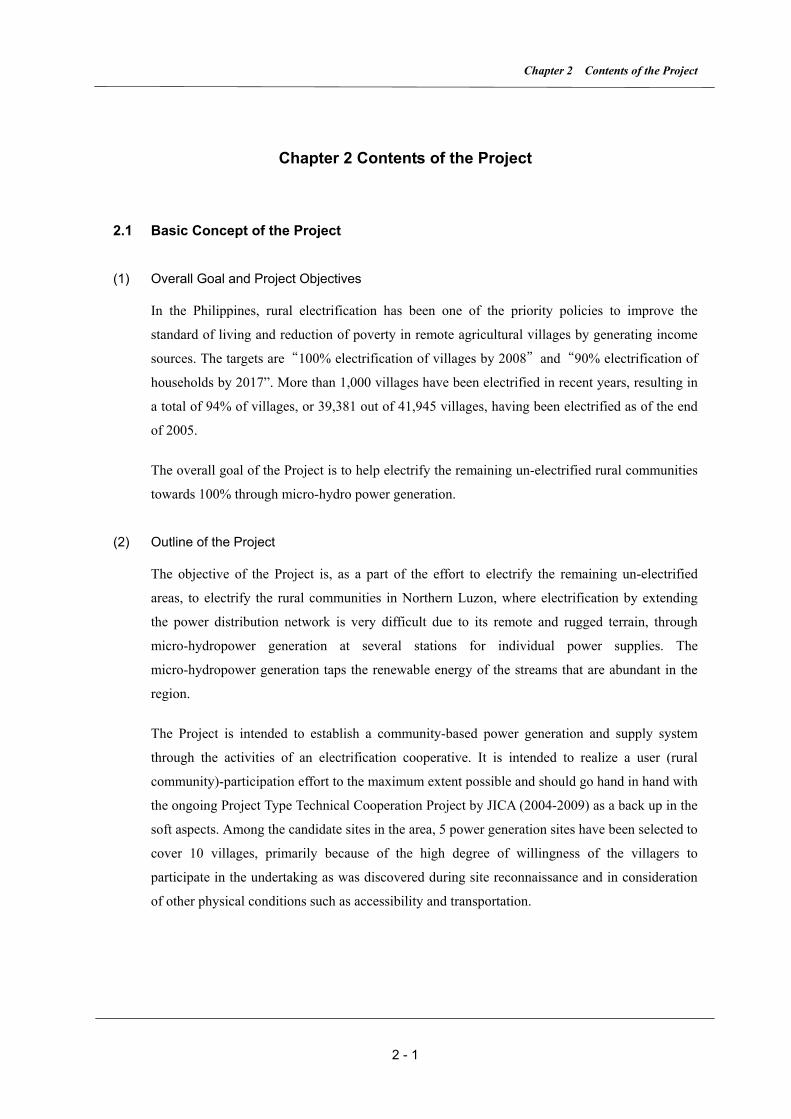
In the Philippines, rural electrification has been one of the priority policies to improve the
standard of living and reduction of poverty in remote agricultural villages by generating income
sources. The targets are “100% electrification of villages by 2008” and “90% electrification of
households by 2017”. More than 1,000 villages have been electrified in recent years, resulting in
a total of 94% of villages, or 39,381 out of 41,945 villages, having been electrified as of the end
of 2005.
The overall goal of the Project is to help electrify the remaining un-electrified rural communities
towards 100% through micro-hydro power generation.
(2) Outline of the Project
The objective of the Project is, as a part of the effort to electrify the remaining un-electrified
areas, to electrify the rural communities in Northern Luzon, where electrification by extending
the power distribution network is very difficult due to its remote and rugged terrain, through
micro-hydropower generation at several stations for individual power supplies. The
micro-hydropower generation taps the renewable energy of the streams that are abundant in the
region.
The Project is intended to establish a community-based power generation and supply system
through the activities of an electrification cooperative. It is intended to realize a user (rural
community)-participation effort to the maximum extent possible and should go hand in hand with
the ongoing Project Type Technical Cooperation Project by JICA (2004-2009) as a back up in the
soft aspects. Among the candidate sites in the area, 5 power generation sites have been selected to
cover 10 villages, primarily because of the high degree of willingness of the villagers to
participate in the undertaking as was discovered during site reconnaissance and in consideration
of other physical conditions such as accessibility and transportation.

The Project for Electrification in Northern Luzon
2 - 2
2.2 Basic Design of the Requested Japanese Assistance
2.2.1 Design Policy
(1) Basic Policies
A total of 14 candidate sites for constructing micro-hydro power stations had been put forth by
the Philippine government at first, however, 2 of them were agreed to be dropped during the
discussion with DOE as it was found that those sites were to be electrified by extension of a
power grid under other schemes.
Site surveys of the 12 sites have been conducted by the Basic Design Study Team, of which 8
feasible sites were selected as having higher priority upon comprehensive evaluation of the
survey results, namely regarding 1) accessibility to the power grid, 2) willingness of the local
community to participate in the undertaking, 3) generating power potential against demand
(200W/households), 4) cost of construction per household.
Moreover, considering accessibility to the sites and expected construction period, 5 sites were
finally picked for inclusion into the Project.
Table 2.1-1 Requested and Selected Sites
Site Province State Generating
Capacity (kW)Comprehensive
evaluation score
Accessibility Construction Period
Notes
1 Maling-1 Balbalan 40 17 OK OK
2 Maling-2 45 18 OK OK
3 Buaya Karinga 12 6 NO
4 Malkusad Pasil 50 17 OK OK
5 Dakalan Tanudan 45 17 OK NO
6 Lubo no data 10 NO
7 Cambulo Banaue 55 19 OK OK
8 Pula 25 16 OK NO
9 Inwaloy Ifugao 15 *1
10 Maga Maoyao 20 12 OK NO
11 Liwo-2 20 18 OK
12 Binalian 20 10 NO
13 Babadi Kayapa Nueva ゙ 25 *1
14 Talicabcab Viskaya 8 10 NO
*1 Power grid will be extended within two years
Five selected sites

Chapter 2 Contents of the Project
2 - 3
(2) Natural Conditions
All equipment and materials will be designed and manufactured to comply with the conditions as
outlined below.
1) The possible generating capacity will be determined by design water flow, which can be
evaluated by flow duration curves based on measured discharge records, to secure stable
power throughout the year.
2) Since construction of major hydraulic structures such as a weir and intake facility have to be
conducted in the river and on the river bank, the construction schedule, particularly in the
rainy season, shall be formulated carefully.
3) Such remote villages can not be approached by vehicle due to lack of developed roads. This
condition will also have to be considered in planning transportation schemes.
(3) Applied Standards and Regulations
The following standards and regulations will be applied in design of the facilities to be
constructed and equipment to be procured under the Project.
1) Civil Engineering Structures
There are no standards for civil engineering structures specifically for the micro-hydro
power generation in either the Philippines or Japan. Functions of both micro-hydro power
and larger scale hydro power facilities are basically the same. Therefore, Japanese standards
for general civil engineering structures will be adopted in the Project.
2) Turbines, Generators and Control/Protection Equipment
In the Philippines, there are no standards for turbines, generators and control/protection
equipment for micro-hydro power generation either, therefore, the pertinent parts of the
international standards, IEC or Japanese standards JIS, JEC, will be applied.
3) Transmission and distribution systems
Equipment and materials that have been commonly used by a power utility company for
Transmission and distribution systems can be procured in the Philippines, therefore
Philippine standards NEA (National Electric Administration and PEC (Philippine Electric
Code) will be employed.
The international system of units (SI) will be applied to the design and manufacture throughout.
(4) Use of Local Subcontractors
The 5 subject sites are scattered in remote regions, therefore, in order to complete the Project
without delay, it is indispensable to engage local construction companies who have ample
The Project for Electrification in Northern Luzon
2 - 4
experience in working under harsh conditions as sub-contractors under the supervision of the
Japanese firm who is engaged as the prime contractor under the Grant Aid program.
Moreover, to ensure quality of the works, to meet the target schedule and for safety control,
design and construction supervision services are to be rendered by a Japanese engineer.
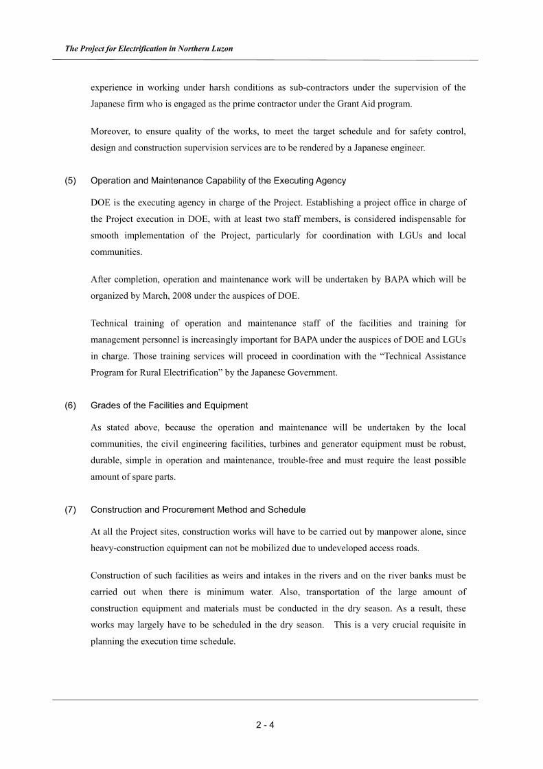
(5) Operation and Maintenance Capability of the Executing Agency
DOE is the executing agency in charge of the Project. Establishing a project office in charge of
the Project execution in DOE, with at least two staff members, is considered indispensable for
smooth implementation of the Project, particularly for coordination with LGUs and local
communities.
After completion, operation and maintenance work will be undertaken by BAPA which will be
organized by March, 2008 under the auspices of DOE.
Technical training of operation and maintenance staff of the facilities and training for
management personnel is increasingly important for BAPA under the auspices of DOE and LGUs
in charge. Those training services will proceed in coordination with the “Technical Assistance
Program for Rural Electrification” by the Japanese Government.
(6) Grades of the Facilities and Equipment
As stated above, because the operation and maintenance will be undertaken by the local
communities, the civil engineering facilities, turbines and generator equipment must be robust,
durable, simple in operation and maintenance, trouble-free and must require the least possible
amount of spare parts.
(7) Construction and Procurement Method and Schedule
At all the Project sites, construction works will have to be carried out by manpower alone, since
heavy-construction equipment can not be mobilized due to undeveloped access roads.
Construction of such facilities as weirs and intakes in the rivers and on the river banks must be
carried out when there is minimum water. Also, transportation of the large amount of
construction equipment and materials must be conducted in the dry season. As a result, these
works may largely have to be scheduled in the dry season. This is a very crucial requisite in
planning the execution time schedule.
Chapter 2 Contents of the Project
2 - 5
2.2.2 Basic Plan
2.2.2.1 Overall Plan
(1) Power Demand Survey of Electrified Barangay
To determine the power generating capacity of the Project, the Basic Design Study Team
conducted a demand survey in Pantikian village that had been electrified by micro-hydropower
generation funded by a Japanese grass-root grant aid.
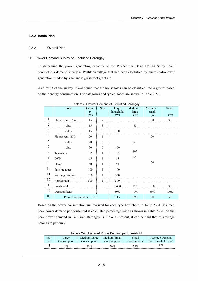
As a result of the survey, it was found that the households can be classified into 4 groups based
on their energy consumption. The categories and typical loads are shown in Table 2.2-1.
Table 2.2-1 Power Demand of Electrified Barangay. Load Capaci
ty (W)
Nos. Large household
(W)
Medium~ large (W)
Medium~ small (W)
Small
(W) 1 Fluorescent 15W 15 2 30 30 2 -ditto- 15 3 45 3 -ditto- 15 10 150 4 Fluorescent 20W 20 1 20 5 -ditto- 20 3 60 6 -ditto- 20 5 100 7 Television 105 1 105 105
8 DVD 65 1 65 65
9 Stereo 50 1 50 50
10 Satellite tuner 100 1 100
11 Washing machine 360 1 360
12 Refrigerator 500 1 500
I Loads total 1,430 275 100 30 II Demand factor 50% 70% 80% 100% III Power Consumption I x II 715 190 80 30
Based on the power consumption summarized for each type household in Table 2.2-1, assumed
peak power demand per household is calculated percentage-wise as shown in Table 2.2-1. As the
peak power demand in Pantikian Barangay is 135W at present, it can be said that this village
belongs to pattern 2.
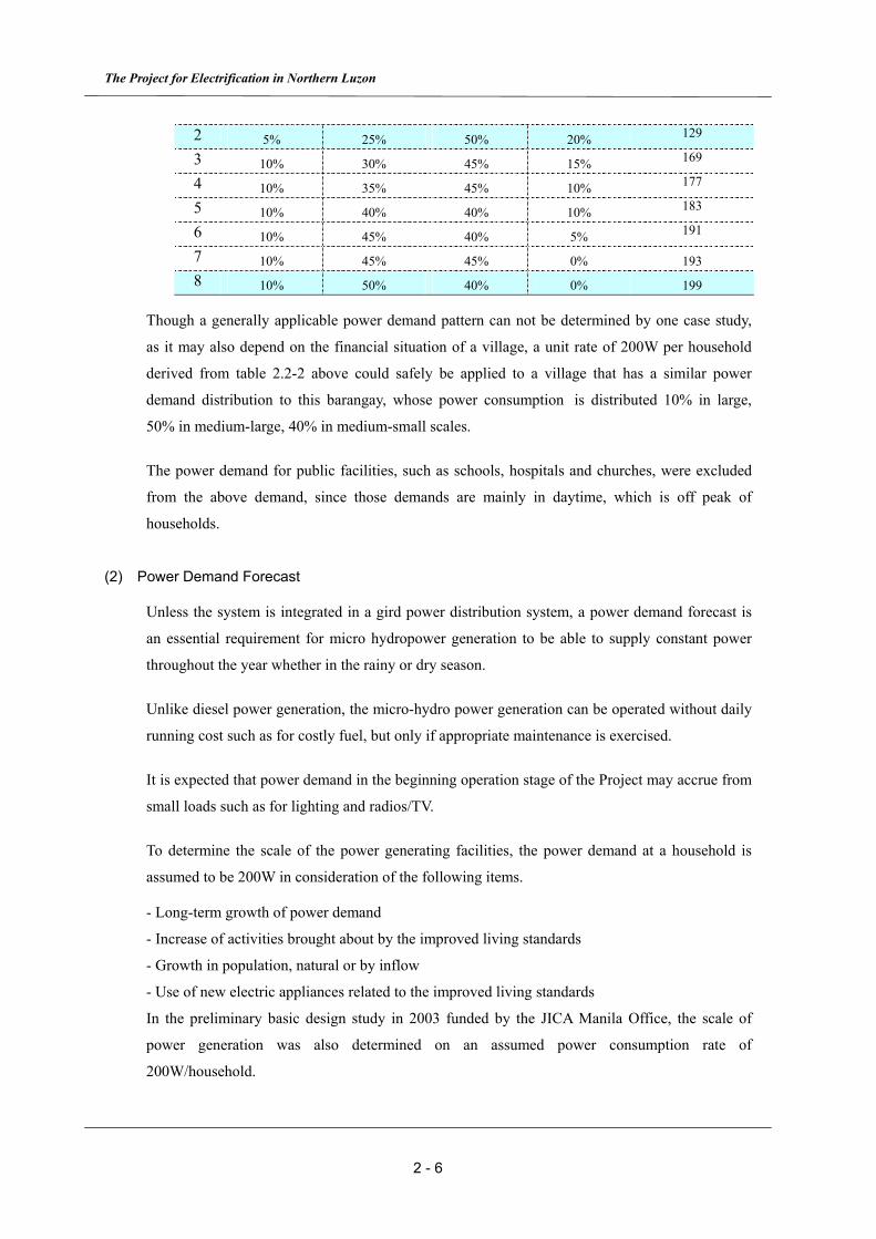
Table 2.2-2 Assumed Power Demand per Household Patt- ern
Large Consumption
Medium-Large Consumption
Medium-Small Consumption
Small Consumption
Average Demand per Household (W)
1 5% 20% 50% 25% 121
The Project for Electrification in Northern Luzon
2 - 6
2 5% 25% 50% 20% 129
3 10% 30% 45% 15% 169
4 10% 35% 45% 10% 177
5 10% 40% 40% 10% 183
6 10% 45% 40% 5% 191
7 10% 45% 45% 0% 193 8 10% 50% 40% 0% 199
Though a generally applicable power demand pattern can not be determined by one case study,
as it may also depend on the financial situation of a village, a unit rate of 200W per household
derived from table 2.2-2 above could safely be applied to a village that has a similar power
demand distribution to this barangay, whose power consumption is distributed 10% in large,
50% in medium-large, 40% in medium-small scales.
The power demand for public facilities, such as schools, hospitals and churches, were excluded
from the above demand, since those demands are mainly in daytime, which is off peak of
households.
(2) Power Demand Forecast
Unless the system is integrated in a gird power distribution system, a power demand forecast is
an essential requirement for micro hydropower generation to be able to supply constant power
throughout the year whether in the rainy or dry season.
Unlike diesel power generation, the micro-hydro power generation can be operated without daily
running cost such as for costly fuel, but only if appropriate maintenance is exercised.
It is expected that power demand in the beginning operation stage of the Project may accrue from
small loads such as for lighting and radios/TV.
To determine the scale of the power generating facilities, the power demand at a household is
assumed to be 200W in consideration of the following items.
- Long-term growth of power demand
- Increase of activities brought about by the improved living standards
- Growth in population, natural or by inflow
- Use of new electric appliances related to the improved living standards
In the preliminary basic design study in 2003 funded by the JICA Manila Office, the scale of
power generation was also determined on an assumed power consumption rate of
200W/household.
Chapter 2 Contents of the Project
2 - 7
2.2.2.2 Supply Areas
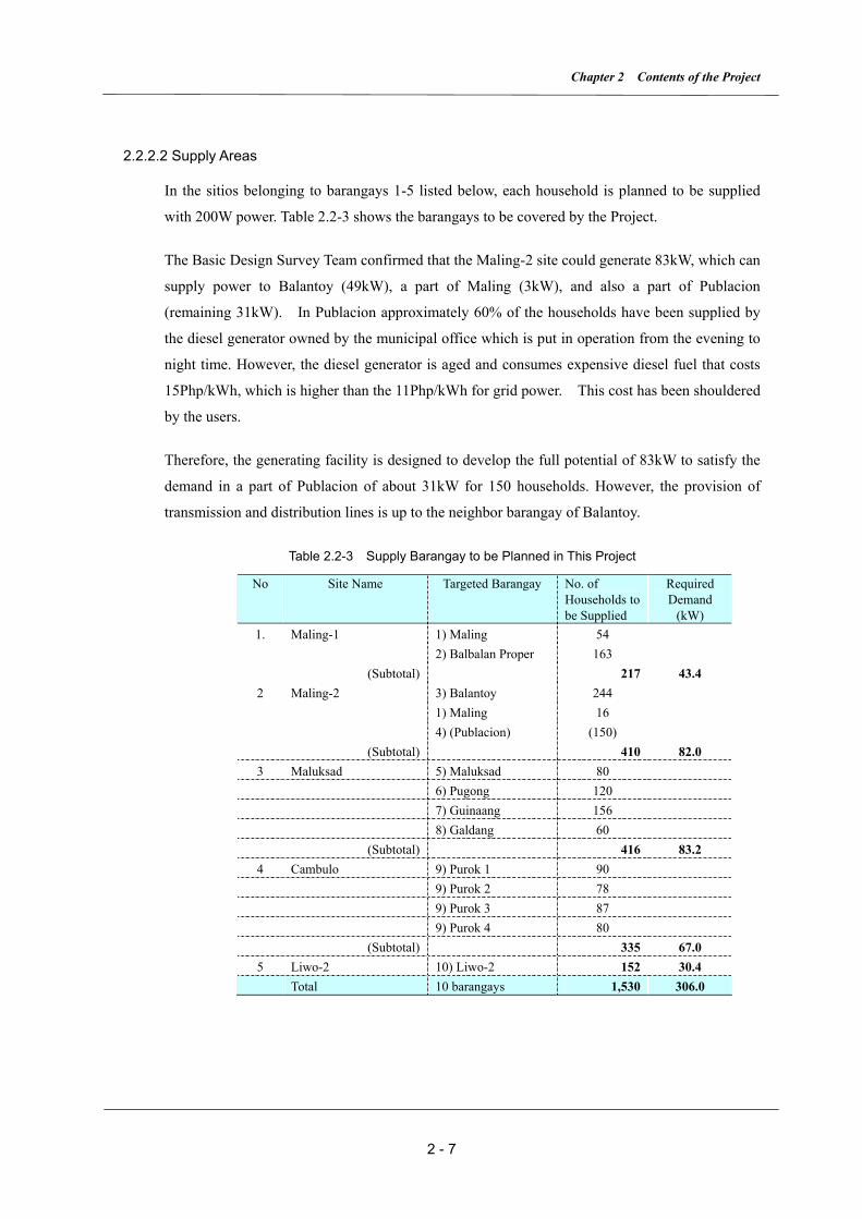
In the sitios belonging to barangays 1-5 listed below, each household is planned to be supplied
with 200W power. Table 2.2-3 shows the barangays to be covered by the Project.
The Basic Design Survey Team confirmed that the Maling-2 site could generate 83kW, which can
supply power to Balantoy (49kW), a part of Maling (3kW), and also a part of Publacion
(remaining 31kW). In Publacion approximately 60% of the households have been supplied by
the diesel generator owned by the municipal office which is put in operation from the evening to
night time. However, the diesel generator is aged and consumes expensive diesel fuel that costs
15Php/kWh, which is higher than the 11Php/kWh for grid power. This cost has been shouldered
by the users.
Therefore, the generating facility is designed to develop the full potential of 83kW to satisfy the
demand in a part of Publacion of about 31kW for 150 households. However, the provision of
transmission and distribution lines is up to the neighbor barangay of Balantoy.
Table 2.2-3 Supply Barangay to be Planned in This Project
No Site Name Targeted Barangay No. of Households to be Supplied
Required Demand
(kW) 1. Maling-1 1) Maling 54 2) Balbalan Proper 163 (Subtotal) 217 43.4 2 Maling-2 3) Balantoy 244 1) Maling 16 4) (Publacion) (150) (Subtotal) 410 82.0 3 Maluksad 5) Maluksad 80 6) Pugong 120 7) Guinaang 156 8) Galdang 60 (Subtotal) 416 83.2 4 Cambulo 9) Purok 1 90 9) Purok 2 78 9) Purok 3 87 9) Purok 4 80 (Subtotal) 335 67.0 5 Liwo-2 10) Liwo-2 152 30.4 Total 10 barangays 1,530 306.0
The Project for Electrification in Northern Luzon
2 - 8
2.2.2.3 Civil Structure Design
In the Philippines, hydropower generation of less than 100kW output is defined as micro
hydropower. The layout and main components of the micro hydropower stations are basically
almost identical to those of large scale hydro power stations, only their scales are different.
Hydropower stations are usually composed of civil engineering structures such as intake weirs,
headrace channels, settling basins, head tanks, penstocks, power houses and tailraces.
The micro hydropower station is usually a run-of-river type without a reservoir. River water is
taken in at the intake weir at a height of 2 to 3 meters, led to the head tank through the open
headrace channel, and then dropped to the generator through the penstock. Power output “P” is
obtained by the product of discharge “Q” and effective head “He” as follows.
P = 9.8*η*Q*He
where “η” is the efficiency of the turbine and generator, normally around 0.6
The design discharge Q is determined based on the measured water flow at nearby river gauging
stations (normally the river flow rate during over 90% of the year is taken as dependable).
(1) Intake Weirs
Intake weir structures are either of concrete gravity type partially replaced with boulders inside
the weir to reduce construction cost or Tyrolean type. The former is to be adopted at the sites of
Maling-2, Maluksad and Cambulo, and the latter at the sites of Maling-1 and Liwo-2.
The height of the weirs is about 2 to 3 meters (weirs higher than 15 meters are called dams). The
shape of the weirs is decided by the structural stability calculations under the assumed flood
condition. Intake mouths and flushing channels are provided with manual gates for operation and
maintenance purposes. The width of the flushing channels is 1.5 to 2 meters in consideration of
the large amount of sand generated under flood conditions. The intake mouths for gravity type
weirs are provided on the river banks at a 90 degree angle to the river flow.
(2) Headrace Channels
Open channels are basically applied to the headrace channels for easy construction and low cost.
Non-pressure pipes are adopted for steep slopes and exposed rock slopes to minimize earthwork
as much as possible, and to secure the stability of the excavated earth slope.

Chapter 2 Contents of the Project
2 - 9
The channel gradient is basically at 1/1000 so that the water flow velocity is kept at about 1m/sec,
to reduce the head loss and to prevent scouring of the channel structures.
The shape of the channel section is decided based on economic considerations and to minimize
the friction loss and in consideration of topographic and geological features at the sites.
The depth of the channel is decided so that freeboard of about 30% of the channel depth is
secured; the range of freeboard is about 20 to 30cm.
The channels to be adopted for given topographic and geological features at the sites are shown
in Table2.2-4
Table2.2-4 Channel Type for Headrace
Type Structure Conditions in which to be Applied
1 Culvert (Rectangular section)
Reinforced concrete • Near intakes where the channel is likely to be inundated by flood and a flood protection wall is difficult to construct.
• Where existing streams or waterways cross the channel. 2 Conduit pipe
(Spherical section)
Half-buried or Underground Hard vinyl chloride pipe or Steel pipe
Over exposed rock slopes or steep slopes where an open channel is impractical or the slope would become unstable with excessive excavation.
3 Open channel (Rectangular section)
Reinforced concrete Where topographic features are gentle and steady. A concrete cap to protect against falling debris, such as from slope collapse or fallen leaves and branches should be installed where deemed necessary.
4 Open channel (Trapezoidal section)
Mortar masonry concrete Where topographic features are gentle and steady and land space can be secured.
(3) Settling Basins
A settling basin is provide in the middle of the headrace channel at Cambulo site where the
headrace channel is 500 m or more in length and detritus from the slope slides is expected to fall
in.
Width of the settling basin is decided so that the water velocity in the basin slows to less than
0.3m/sec.
The settling basin is made of reinforced concrete and equipped with a flushing gate and spillway.
Head tanks will also serve as settling basins for sand and silt at all sites except Cambulo.
(4) Head Tanks
A head tank is to be provided at the junction between the headrace channel and the penstock.
The Project for Electrification in Northern Luzon
2 - 10
Capacity of the head tank is decided to enable supply of the design discharge to the penstock for
two minutes or more, even if there is no water from the headrace channel. Moreover, the width of
a head tank is decided so that the water velocity in the head tank is less than 0.3m/sec, to add the
function of a settling basin as well.
The head tank is made of reinforced concrete and equipped with a flushing gate and spillway.
At Cambulo site, the head tank is also designed as a settling basin to remove the last of the
sediments.
(5) Penstocks
Short steel pipes are connected with flange joints, because quality welding work is difficult in the
field and access to the sites is generally bad for hauling lengthy pieces
A unit length for pipes of 6 meters is adopted at the sites of Maling-1, Maling-2 and Maluksad
where the access is comparatively good. A unit pipe length of 3 meters is adopted at the sites of
Cambulo and Liwo-2 because there are narrow or steep slopes in the access foot paths to these
sites.
The anchor blocks and saddles are made of reinforced concrete, and the interval between saddles
is basically 6 meters.
For the exposed pipe, expansion joints will be installed in consideration of temperature variation
while for the underground pipe no expansion joints are provided.
(6) Power Houses
Ordinary above ground type structures will be used for the power houses, where enough space
for the generators and control panels etc. will be provided.
The width and length of the power houses will be around 5 to 6 meters, and the height about 3
meters. The maximum depth of the outlet pit is to be about 3 meters from the ground floor of the
power house.
The floor and columns will be made of reinforced concrete and the walls of cement mortar
finished concrete blocks. The roofs are to be made of galvanized iron sheets that are supported by
timber beams. Storage space for maintenance tools and spare parts is also to be provided in the
power houses.
Open channels made of reinforced concrete will be provided for the tailrace channels.
Chapter 2 Contents of the Project
2 - 11
(7) Others
Gabion or masonry retaining walls will be adopted for slope protection works over steep
excavated slopes (except rock slopes) and in collapse-prone slopes. Near the intake, gabions or
retaining walls are to be provided protect river banks from scour. It is noted that blasting work
will have to be executed where large boulder removal or rock excavation is needed for the
structures or slopes.
In Cambulo site, the planned location of the headrace channel, settling basin and head tank
encroaches upon existing rice terraces in some portions. In these places, reinforcement of existing
masonry walls or securing of drainage for the rice terraces will be exercised to minimize the
influence on the rice terraces.
For access to the power stations and the safe patrolling of civil engineering structures, footpaths
with a width of about 50 cm will be constructed at all sites.
Features of the five micro-hydropower stations are shown in Table2.2-5.

The Project for Electrification in Northern Luzon
2 - 12
Table2.2-5 Features of the Five Micro Hydropower Stations Unit Maling-1 Maling-2 Malksad Cambulo Liwo-2
km2 16.56 30.39 52.35 51.10 13.54
m3/sec 0.30 0.50 0.87 0.82 0.26
m3/sec 0.31 0.52 0.68 0.65 0.29m 25.520 26.450 20.240 19.785 22.180m 22.930 23.880 19.310 18.145 20.840
kW 47.8 83.3 86.8 77.9 38.1pc 1 1 1 1 1
Reversal pump/Cross-flow
Reversal pump/Cross-flow
Reversal pump/Cross-flow
Reversal pump/Cross-flow
Reversal pump/Cross-flow
Type Tyloean Concrete gravity Concrete gravity Concrete gravity Tyloean
Structure Concrete Boulder core concrete Boulder core concrete Boulder core concrete Concrete
Length m 16.5 27.0 25.0 20.0 14.0
Height m 2.0 2.5 2.5 2.5 2.0
Structure Reinforced concreteInside dimension m B3.5×H1.8 (t=0.2)
Length m 10.0
Culvert Structure Reinforced concreteInside dimension m B1.4 x H1.4
Length m 40.0
Open channel Structure Reinforced concrete Reinforced concrete Reinforced concrete Reinforced concrete Reinforced concrete
(Square shape) Inside dimension m B0.7×H0.7 (t=0.2) B0.9×H0.9 (t=0.2) B1.0×H1.0 (t=0.2) B1.0×H1.0 (t=0.2) B0.75× H0.75 (t=0.2)
Length m 103.0 11.0 277.0 142.0 388.0
Open channel Structure Mortar masonry concrete
(Trapezoidal Inside dimension m B2.0×H1.0 (t=0.3)
section) Length m 290.0Conducting pipe Structure Steel pipe Steel pipe Steel pipe Steel pipe
Inside dimension m D=650mm (t=4mm) D=700mm (t=4mm) D=700mm (t=4mm) D=650mm (t=6mm)
Length m 32.0 67.0 123.0 6.0
Structure Reinforced concrete Reinforced concrete Reinforced concrete Reinforced concrete Reinforced concreteInside dimension m B4.0×H2.5 (t=0.2) B2.5×H2.7 (t=0.2) B3.0×H3.0 (t=0.2) B4.0×H3.4 (t=0.2) B2.75×H2.9 (t=0.2)
Length m 7.0 20.0 20.5 14.0 9.0
Type Underground Buried & Underground Underground Buried & Underground Buried & Underground
Structure Steel pipe Steel pipe Steel pipe Steel pipe Steel pipeInside diameter m D=400mm (t=6mm) D=600mm (t=6mm) D=600mm (t=6mm) D=500mm (t=6mm) D=400mm (t=6mm)
Length m 135.0 172.0 31.0 29.0 47.0
Anchor block pc 5 7 2 2 3
Saddle pc 1 1 1 2 3
Type Above ground Above ground Above ground Above ground Above ground
Structure
Base: ConcreteWall: Concrete block
+ MortarRoof: Galvanized iron
+ Timber
Base: ConcreteWall: Concrete block
+ MortarRoof: Galvanized iron
+ Timber
Base: ConcreteWall: Concrete block
+ MortarRoof: Galvanized iron
+ Timber
Base: ConcreteWall: Concrete block
+ MortarRoof: Galvanized iron
+ Timber
Base: ConcreteWall: Concrete block
+ MortarRoof: Galvanized iron
+ Timber
Inside diameter m B4.4×L4.4 (t=0.3) B5.7×L4.7 (t=0.3) B5.7×L5.7 (t=0.3) B5.4×L5.4 (t=0.3) B4.4×L4.4 (t=0.3)Height of house m 3.0 3.0 3.0 3.0 3.0
Pit depth m 2.5 3.0 3.5 3.4 1.2
Open channel Structure Reinforced concrete Reinforced concrete Reinforced concrete Reinforced concrete Reinforced concrete
(Square shape) Inside dimension m B1.2×H0.5 B1.4×H0.5 B1.4×H0.5 B1.5×H0.5 B1.0 x H0.5
Length m 6.0 7.0 10.0 15.0 6.0
Gross headDesign discharge*
Available discharge
Number of turbine generator
Generator output
Type of turbine
Effective head
*:The efficiency of reversal pump greatly depends on effective head and design discharge. Due to the design condition of using the reversal pump of thestandard product, the design discharges for Maling-1, Maling-2 and Liwo-2 are a little bigger than their available discharge respectively as a result.
Tailrace
Power house
Penstock
Head tank
Headrace channel
Settling basin
Intake weir
Catchment Area
Chapter 2 Contents of the Project
2 - 13
2.2.2.4 Basic Design of Hydro Power Plants
Power output of the hydropower plants is estimated by available water flow and water column
pressure at the candidate sites. Potential available water at respective sites is obtained from the
hydrologic and meteorological data. The water flow at a weir site is obtained by catchment area
and runoff data. Referring to this data, the flow duration curve is prepared for determining
turbine discharge. In this study, 90%〜95% dependable flow rate is taken for the turbine
discharge. Acting turbine head is obtained by level differences between intake and tailrace
water levels, which produces the optimum design of waterway structures according to the site
conditions. Effective head for the turbines is obtained by reduction of head loss in the
waterways. Based on such available water and head and power demand at respective project
sites and with an aim at meeting the consumer demand to the maximum extent, installation
capacity of each power plant is finally decided.
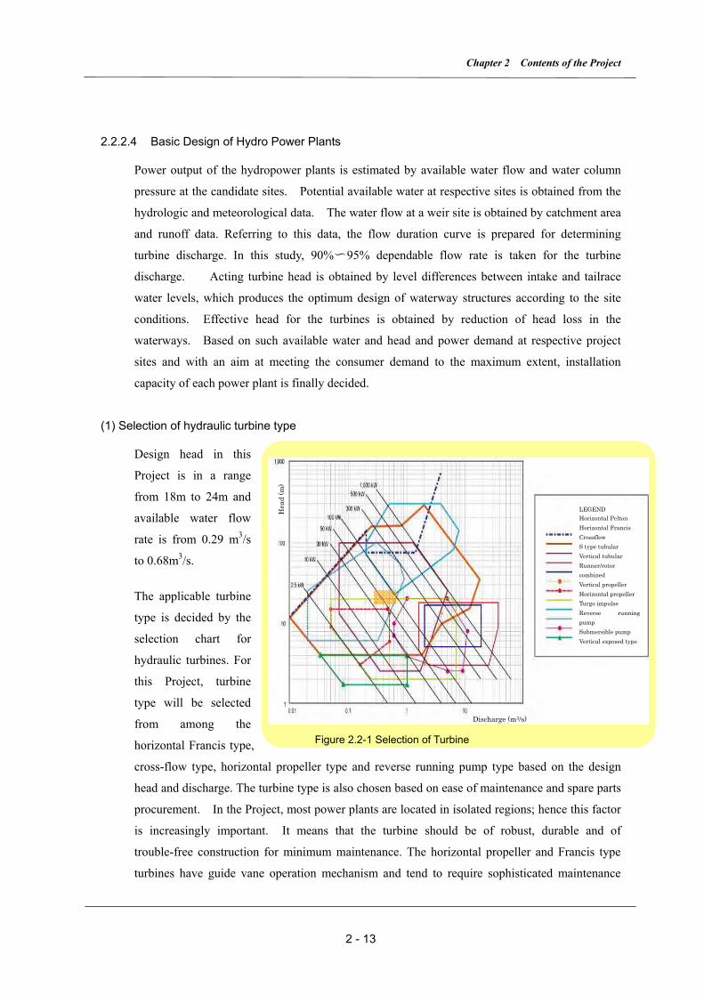
(1) Selection of hydraulic turbine type
Design head in this
Project is in a range
from 18m to 24m and
available water flow
rate is from 0.29 m3/s
to 0.68m3/s.
The applicable turbine
type is decided by the
selection chart for
hydraulic turbines. For
this Project, turbine
type will be selected
from among the
horizontal Francis type,
cross-flow type, horizontal propeller type and reverse running pump type based on the design
head and discharge. The turbine type is also chosen based on ease of maintenance and spare parts
procurement. In the Project, most power plants are located in isolated regions; hence this factor
is increasingly important. It means that the turbine should be of robust, durable and of
trouble-free construction for minimum maintenance. The horizontal propeller and Francis type
turbines have guide vane operation mechanism and tend to require sophisticated maintenance
Figure 2.2-1 Selection of Turbine
Discharge (m3/s)
LEGEND Horizontal Pelton Horizontal Francis Crossflow S type tubular Vertical tubular Runner/rotor combined Vertical propeller Horizontal propeller Turgo impulse Reverse running pump Submersible pump Vertical exposed type
Hea
d (m
)
The Project for Electrification in Northern Luzon
2 - 14
service which would be reflected in higher operation costs. The reverse running pump is
fabricated of castings which produces metals strong enough to withstand severe operation
conditions. However, it has a disadvantage that the pump tends to get less efficient under low
load operation. In case of a load shutdown, on the other hand, the reverse running pump can
withstand runaway speed operation continuously even if the speed rises to over 150% of the rated
speed, that is another advantage over the other types. It is also expected that the pump can be
selected from the standard model pumps, which means there is no need to design the specific new
manufacture. This fact would certainly contribute to reduction of the cost
Cross flow turbines are commonly used for micro-hydro power stations in the Philippines due to
their advantage of simple operation and maintenance.
In consequence of the above discussion, it is judged that the reverse running pump turbine and
cross flow turbines are the most suitable types for these micro power plants.
Turbine load change and speed control are generally adjusted by guide vane opening/closing in
normal hydraulic turbines, but the reverse running pumps can not follow the system load change
due to its construction features. So, in order to correspond to the load change, dummy loads will
be placed in the powerhouse tailraces so that the generator output is always kept under constant
load. A main inlet valve will be provided in each unit so that it can be started and stopped
manually.
(2) Selection of Generators
There are two possible generator types for micro power plants; one is the synchronous generator
and the other is the induction generator. The micro power plants in the Project are to be
constructed in remote areas where extension of the grid distribution line is not practical. The
induction generator generally requires supply of exciting current to kick in. The synchronous
generator can be adopted as it is independent of power distribution system.
The generator terminal voltage will be selected from its capacity and speed. Planned capacities of
the generators in the Project are in a range from 30kW to 90kW and considering the fact that the
standard voltage in the Philippines is 415V for low tension circuits, the applied voltage should
also be 415V, and in a 3-phase and 3-wire system. Dimensions of generators with higher speed
are generally smaller and become more economical. For the generators of the above range
capacity, characteristics are generally of speed 1,800rpm with 4-poles or of 1,200 rpm with 6-
poles. In this Project, 1, 200 rpm is recommended considering the runaway speed of the turbine at
the time of load shut-down. Turbine speed will be decided based on the available turbine
discharge and water head but this speed is not always consistent with that of the generator. To
Chapter 2 Contents of the Project
2 - 15
counter this situation, a speed reduction gear is to be provided so that the turbine and generator
speed 1,200 rpm is maintained.
(3) Control of generating power plants
Operation of generation equipment will be supervised and controlled by a resident operator. The
operation system will, in principle, be of continuous operation.
1) Generator Control Systems:
Each generating plant is to be controlled by an automatic control system. Output voltage is to be
automatically controlled by a voltage regulator.
2) Load Control
Generator output will be controlled by a dummy load governor to eliminate the effect of
fluctuation of the demand side. Operation mechanism is such that the gap between generator
output and demand load is automatically compensated for by means of frequency variation by the
Electrical Load Controller (ELC).
(4) Design of hydropower plants
Installation capacity of the five (5) power plants is determined to be in a range from
30kW~90kW based on the following considerations.
Each respective power plant should produce a constant output throughout the year based on
civil engineering structural design and study of the available water discharge.
Available water discharge will fluctuate enormously in the dry and wet seasons, therefore,
the required water for the power generation will be confined within 90% dependable water
flow discharge from the duration curve.
Outline of the generating equipment is as follows.
1) Design of Generating Equipment
i) Hydraulic turbine
Type : Horizontal double suction reverse running pump or Cross flow
Governor : Dummy load governor Inlet valve : Manually operated butterfly valve Rating : Refer to table 2-2-6
ii) Generator
Type : 3-phase brushless synchronous generator

The Project for Electrification in Northern Luzon
2 - 16
Frequency : 60Hz Connection : 3 phase 3 wire Insulation class : F class on stator and rotor windings Rating : Refer to table 2-2-6
iii) Control panels
Type : Indoor, enclosed self-standing type
Control and protection equipment
: Annunciator for status indicator, measuring instruments, protection relays, AVR, Auxiliary relays, 400V switchgears, voltage and current transformers etc.
Table-2-2-6 Basic Design of Generating Equipment Name of plant site Equipment Specification Maling -1 Maling -2 Maluksad Cambulo Liwo-2
Turbine Effective head (m) 22.93 23.98 19.31 18.145 20.84 Discharge (m3/s) 0.31 0.52 0.68 0.65 0.26 Efficiency 0.78 0.82 0.79 0.79 0.78 Max. output (kW) 54 98 102 92 42 Speed (rpm) 1,200 700 800 800 1,200
Speed increaser
Flat gear (ratio) - 7/12 3/4 3/4 -
Generator Rated capacity (kVA)
70 120 130 120 60
Rated voltage (V) 415 415 415 415 415 Efficiency 88.0 87.0 88.0 88.0 87.0 Power factor 0.8 0.8 0.8 0.8 0.8
Speed (rpm) 1,200 1,200 1,200 1,200 1,200 2) Operation and control systems
Control and operation will be supervised by a resident operator. Start and stop operation of the
generator is effected by manual operation of the main inlet valve.
3) Protection system i) Emergency stop
Emergency stop will be initiated by the protective relays and a generator main circuit breaker will
be opened to isolate the generator from the power distribution system. At the same time, the
operator will close the main inlet valve by hand to stop the turbine safely.
Heavy fault alarm will be given by a bell furnished on the generator control panel and the
operator will close the main inlet valve immediately. Status of operation and kind of heavy fault
will also be indicated on the annunciator in the control panel.
On serious fault conditions, a lock-out relay will be kicked in so that the generator could not be
re-started until after confirmation of removal of the cause of the fault.
ii) Alarms
Light fault alarm will be given by a buzzer on the generator control panel. The operator will take

Chapter 2 Contents of the Project
2 - 17
the proper action corresponding to the kind of fault and its extent to protect the generator from
any damage.
A bell and buzzer alarm can be reset after some period by the operator, but in case of serious fault,
the lamp indication is made so that it can not be reset until removal of the cause of fault by way
of a lock-out relay.
2.2.2.5 Transmission and Distribution Facilities
(1) Design Policy
There are several kinds of specifications for the transmission/distribution facilities and equipment,
which have been standardized in the PEC (Philippine Electric Code) and NEA (National Electric
Administration). In the Project, the design of transmission and distribution lines will follow
these standards in principle. Because the selected barangays and sitios are not planned to be
integrated into the power company’s existing grids, the hydro-power generating facilities are to
be operated individually and independently. Once the micro generating facilities are completed,
residents in the barangays are supposed to undertake the operation and maintenance of them by
establishing an organization to this end. Therefore, the installed equipment has to be designed
and manufactured for reliability and durability because the residents have to determine the causes
of the problems that have occurred and solve them on their own. In addition, the design must
take into account availability of spare parts and consumables in the Philippines for easy
maintenance service.
1) Applicable criteria and standards
For the equipment and materials for transmission and distribution facilities, the
specifications of PEC and NEA will generally be followed. When not stipulated in those
standards, IEC shall be adapted.
(a) Philippine Electric Code (PEC) (b) National Electric Administration (NEA) (c) International Electrotechnical Commission(IEC)
2) Supply Demarcation
For those who reside near the five Project sites, power will be supplied with a voltage that is
determined by weighing the balance between the design generating capacity of the power
stations and the communities’ (barangay, sitio) power demand.
As a result, at the power station, the primary voltage of the generator 400-440V is stepped
up by a transformer to 13.2kV for transmission of power over the transmission lines.
The Project for Electrification in Northern Luzon
2 - 18
In Japan, the transmission and distribution systems normally comprise supply and
construction up to single phase transformer (7.62/0.24kV). For further lower voltage power
distribution (240V), supply of materials only such as electric poles, cables and accessories
is included in the scope of the transmission/distribution work. Drop wires and Watt-hour
meters are not included. The same principle will be employed in the Project as well.
3) Applicable Frequency and Voltage
In the Philippines, a frequency of 60Hz is being used throughout, and for medium voltage
transmission lines, rated voltage is 13.2/7.62kV. Rated voltage for lower power
distribution is 415/240V.
4) Supply System
Generally, weight of conductor for three (3)-phase, three(3)-wire supply systems is about
75% that for single-phase, two-wire systems, the former being more economical and
reasonable from an economic point of view.
In the Philippines, however, use of a neutral line on the secondary side of the transformer is
often exercised to materialize single-phase, two (2)-wire distribution due to absence of
three-phase power use at the consumer side. There are a number of cases in the
Philippines‘s own undertaking as well as in Japan’s development assistance projects that
have employed three (3)-phase, four (4)-wire supply systems from the secondary side of the
transformer at the power station to enable single-phase, two (2)-wire distribution for this
type of power demand at the consumer side. Balancing the loads on R, S and T phases is the
critical factor in these cases.
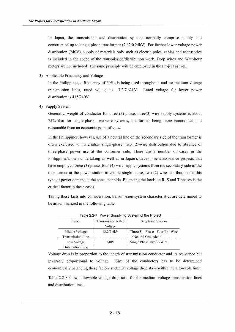
Taking these facts into consideration, transmission system characteristics are determined to
be as summarized in the following table.
Table 2.2-7 Power Supplying System of the Project Type Transmission Rated
Voltage Supplying System
Middle Voltage Transmission Line
13.2/7.6kV Three(3) Phase Four(4) Wire(Neutral Grounded)
Low Voltage Distribution Line
240V Single Phase Two(2) Wire
Voltage drop is in proportion to the length of transmission conductor and its resistance but
inversely proportional to voltage. Size of the conductors has to be determined
economically balancing these factors such that voltage drop stays within the allowable limit.
Table 2.2-8 shows allowable voltage drop ratio for the medium voltage transmission lines
and distribution lines.
Chapter 2 Contents of the Project
2 - 19
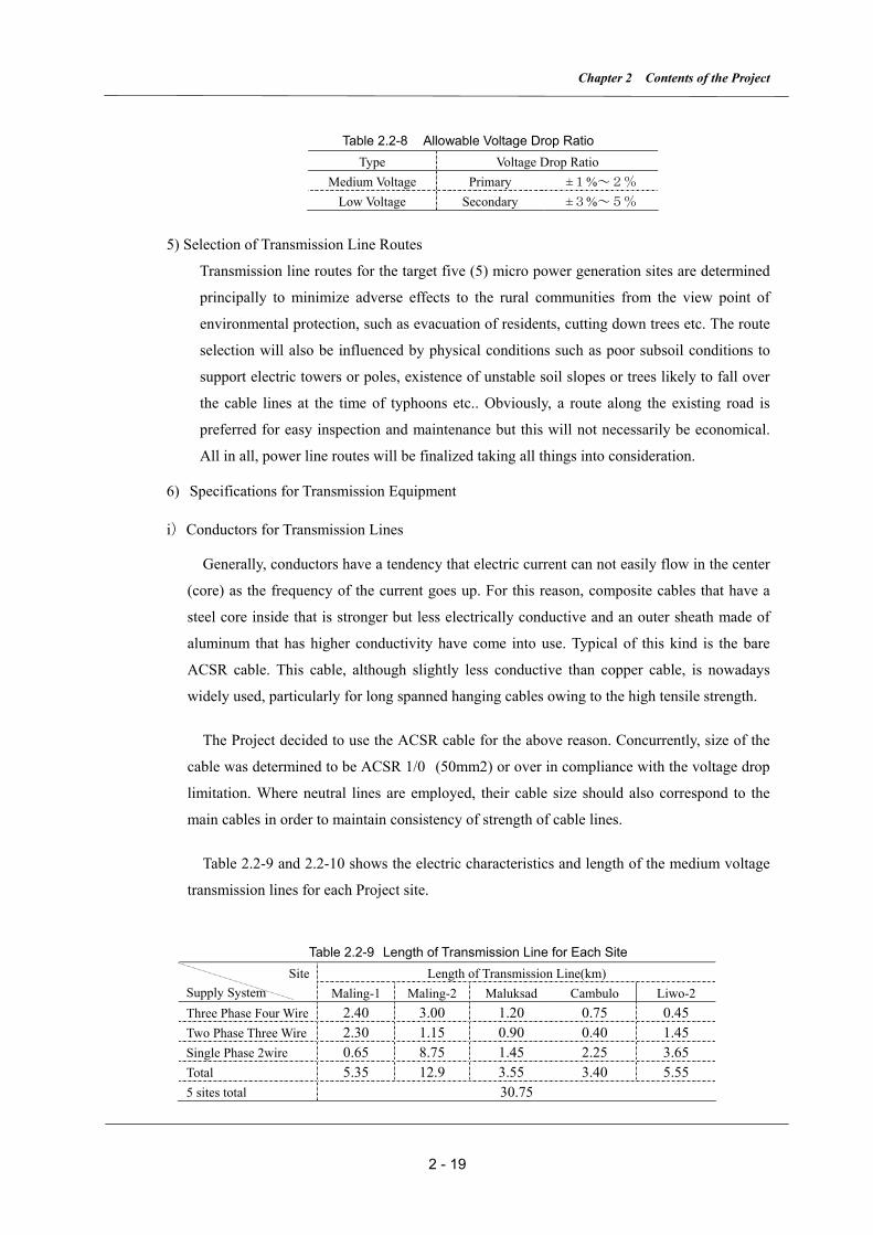
Table 2.2-8 Allowable Voltage Drop Ratio Type Voltage Drop Ratio
Medium Voltage Primary ±1%~2% Low Voltage Secondary ±3%~5%
5) Selection of Transmission Line Routes
Transmission line routes for the target five (5) micro power generation sites are determined
principally to minimize adverse effects to the rural communities from the view point of
environmental protection, such as evacuation of residents, cutting down trees etc. The route
selection will also be influenced by physical conditions such as poor subsoil conditions to
support electric towers or poles, existence of unstable soil slopes or trees likely to fall over
the cable lines at the time of typhoons etc.. Obviously, a route along the existing road is
preferred for easy inspection and maintenance but this will not necessarily be economical.
All in all, power line routes will be finalized taking all things into consideration.
6) Specifications for Transmission Equipment
i)Conductors for Transmission Lines
Generally, conductors have a tendency that electric current can not easily flow in the center
(core) as the frequency of the current goes up. For this reason, composite cables that have a
steel core inside that is stronger but less electrically conductive and an outer sheath made of
aluminum that has higher conductivity have come into use. Typical of this kind is the bare
ACSR cable. This cable, although slightly less conductive than copper cable, is nowadays
widely used, particularly for long spanned hanging cables owing to the high tensile strength.
The Project decided to use the ACSR cable for the above reason. Concurrently, size of the
cable was determined to be ACSR 1/0 (50mm2) or over in compliance with the voltage drop
limitation. Where neutral lines are employed, their cable size should also correspond to the
main cables in order to maintain consistency of strength of cable lines.
Table 2.2-9 and 2.2-10 shows the electric characteristics and length of the medium voltage
transmission lines for each Project site.
Table 2.2-9 Length of Transmission Line for Each Site Length of Transmission Line(km) Site
Supply System Maling-1 Maling-2 Maluksad Cambulo Liwo-2 Three Phase Four Wire 2.40 3.00 1.20 0.75 0.45 Two Phase Three Wire 2.30 1.15 0.90 0.40 1.45 Single Phase 2wire 0.65 8.75 1.45 2.25 3.65 Total 5.35 12.9 3.55 3.40 5.55 5 sites total 30.75

The Project for Electrification in Northern Luzon
2 - 20
Table 2.2-10 Total Length of Conductors for Each Site
Site Required Length of Conductors (km) Supply System Maling-1 Maling-2 Maluksad Cambulo Liwo-2
ACSR 1/0 18.69 34.6 10.92 9.14 8.9 Total 87.45
In this Project, procuring 13.2kV transmission equipment and materials and also those of
low voltage distribution line are to be planned as mentioned below. The equipment and
materials are planned to be transported to the end point of the 2nd transportation by the
Japanese Side. Construction to string low voltage distribution lines shall be conducted by
the Philippine side.
Table 2.2-11 Length of Low Voltage Distribution Line for Each Site
Length of Low Voltage Distribution Line (km) SiteSupply System Maling-1 Maling-2 Maluksad Cambulo Liwo-2
Single Phase 2wire 3.67 4.69 5.56 4.66 3.55 5 sites total 22.13
ii)Support Poles for Transmission Lines
For supporting the 13.2kV transmission lines, hollow core steel poles will be used in this
Project because of easy availability in the Philippines.
Length of the poles will be determined to secure the required minimum clearance to the
surrounding structures and nearby trees. Basically, 30(ft) standard poles will be used because
of the constraints in transportation. Length of poles will further be examined from the view
point of clearance from the ground as the case may be. Given that the clearance from the
poles is not sufficient, 40(ft) or 50(ft) poles will be adopted. Embedding length of pole in the
ground will comply with the minimum embedding length prescribed by NEA as summarized
in the table below. Span of hanging cables will generally be 40-50m. For other matters,
reference is made to the NEW ENGINEERING BULLETIN DX1320 of NEA.
Table 2.2-12 Embedding depth of poles
Length of Pole(ft) Embedding depth(ft)
30 5.5 40 6.0 50 7.0
Chapter 2 Contents of the Project
2 - 21
iii) Pole-mounted transformers
Pole-mounted transformers will be installed at the center of load at each barangay or sitio
where voltage is to be stepped down to 240V. Table 2.2-13 shows the specifications of the
standard pole-mounted transformers of NEA. Capacity of the transformers to be installed is
determined by picking adequate models from this table in consideration of the demand and
utilization factors of the barangay. Selected transformer capacities for the Project sites are
illustrated in the attached drawings.
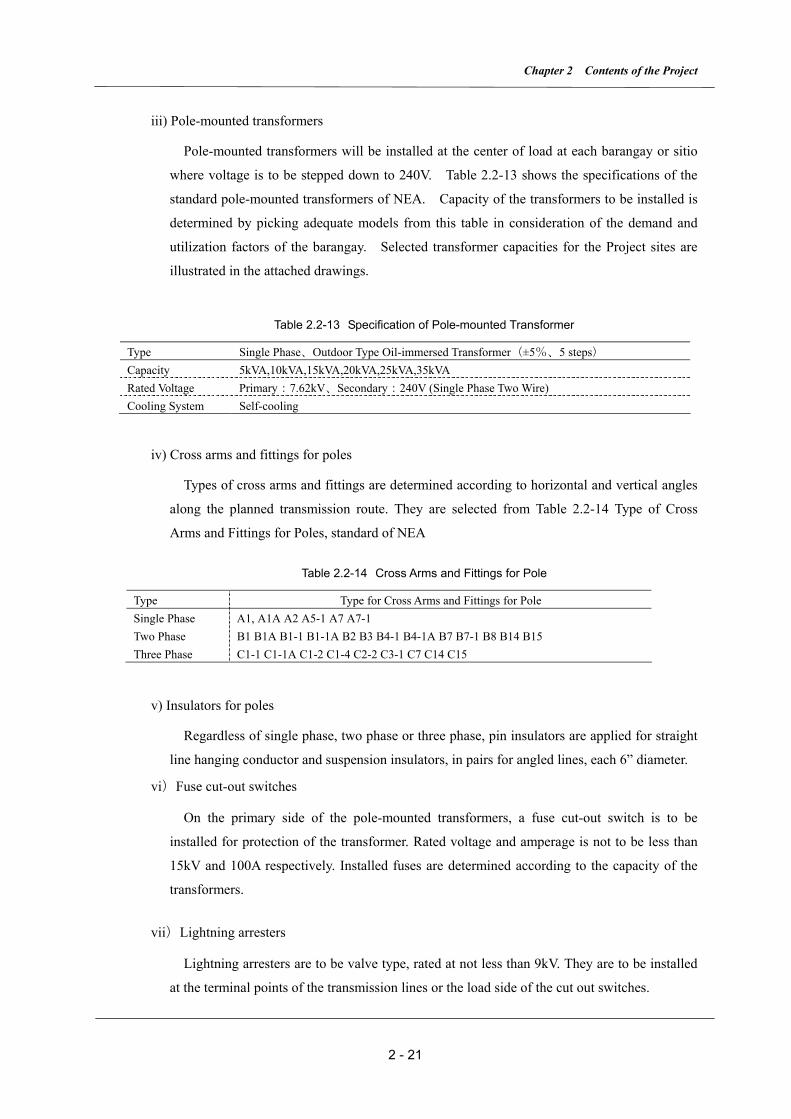
Table 2.2-13 Specification of Pole-mounted Transformer
Type Single Phase、Outdoor Type Oil-immersed Transformer(±5%、5 steps) Capacity 5kVA,10kVA,15kVA,20kVA,25kVA,35kVA Rated Voltage Primary:7.62kV、Secondary:240V (Single Phase Two Wire) Cooling System Self-cooling
iv) Cross arms and fittings for poles
Types of cross arms and fittings are determined according to horizontal and vertical angles
along the planned transmission route. They are selected from Table 2.2-14 Type of Cross
Arms and Fittings for Poles, standard of NEA
Table 2.2-14 Cross Arms and Fittings for Pole
Type Type for Cross Arms and Fittings for Pole Single Phase A1, A1A A2 A5-1 A7 A7-1 Two Phase B1 B1A B1-1 B1-1A B2 B3 B4-1 B4-1A B7 B7-1 B8 B14 B15 Three Phase C1-1 C1-1A C1-2 C1-4 C2-2 C3-1 C7 C14 C15
v) Insulators for poles
Regardless of single phase, two phase or three phase, pin insulators are applied for straight
line hanging conductor and suspension insulators, in pairs for angled lines, each 6” diameter.
vi)Fuse cut-out switches
On the primary side of the pole-mounted transformers, a fuse cut-out switch is to be
installed for protection of the transformer. Rated voltage and amperage is not to be less than
15kV and 100A respectively. Installed fuses are determined according to the capacity of the
transformers.
vii)Lightning arresters
Lightning arresters are to be valve type, rated at not less than 9kV. They are to be installed
at the terminal points of the transmission lines or the load side of the cut out switches.
The Project for Electrification in Northern Luzon
2 - 22
viii) Grounding devices
Grounding devices are to be installed on the distribution transformers, lightning arresters,
metal encasements of electric equipment and other required devices for protection of the
transmission system. The grounding devices will generally comply with NEA standards.
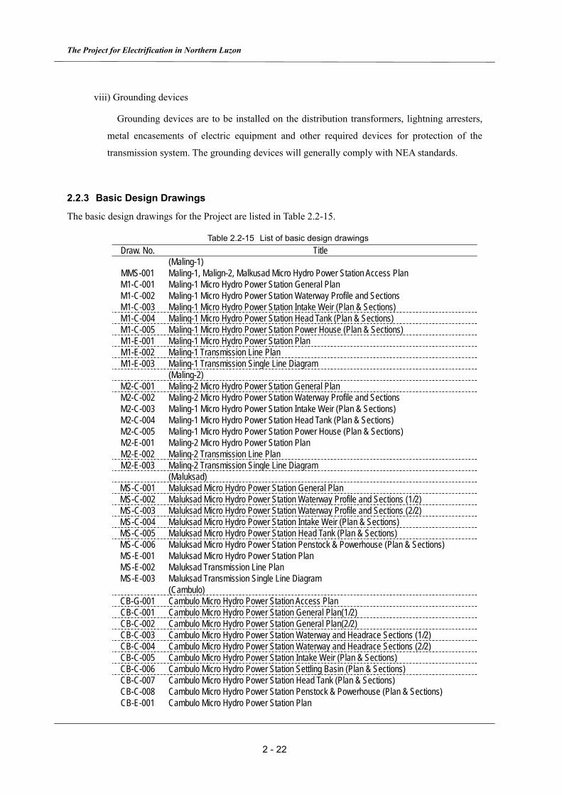
2.2.3 Basic Design Drawings
The basic design drawings for the Project are listed in Table 2.2-15.
Table 2.2-15 List of basic design drawings Draw. No. Title
(Maling-1) MMS-001 Maling-1, Malign-2, Malkusad Micro Hydro Power Station Access Plan M1-C-001 Maling-1 Micro Hydro Power Station General Plan M1-C-002 Maling-1 Micro Hydro Power Station Waterway Profile and Sections M1-C-003 Maling-1 Micro Hydro Power Station Intake Weir (Plan & Sections) M1-C-004 Maling-1 Micro Hydro Power Station Head Tank (Plan & Sections) M1-C-005 Maling-1 Micro Hydro Power Station Power House (Plan & Sections) M1-E-001 Maling-1 Micro Hydro Power Station Plan M1-E-002 Maling-1 Transmission Line Plan M1-E-003 Maling-1 Transmission Single Line Diagram
(Maling-2) M2-C-001 Maling-2 Micro Hydro Power Station General Plan M2-C-002 Maling-2 Micro Hydro Power Station Waterway Profile and Sections M2-C-003 Maling-1 Micro Hydro Power Station Intake Weir (Plan & Sections) M2-C-004 Maling-1 Micro Hydro Power Station Head Tank (Plan & Sections) M2-C-005 Maling-1 Micro Hydro Power Station Power House (Plan & Sections) M2-E-001 Maling-2 Micro Hydro Power Station Plan M2-E-002 Maling-2 Transmission Line Plan M2-E-003 Maling-2 Transmission Single Line Diagram
(Maluksad) MS-C-001 Maluksad Micro Hydro Power Station General Plan MS-C-002 Maluksad Micro Hydro Power Station Waterway Profile and Sections (1/2) MS-C-003 Maluksad Micro Hydro Power Station Waterway Profile and Sections (2/2) MS-C-004 Maluksad Micro Hydro Power Station Intake Weir (Plan & Sections) MS-C-005 Maluksad Micro Hydro Power Station Head Tank (Plan & Sections) MS-C-006 Maluksad Micro Hydro Power Station Penstock & Powerhouse (Plan & Sections) MS-E-001 Maluksad Micro Hydro Power Station Plan MS-E-002 Maluksad Transmission Line Plan MS-E-003 Maluksad Transmission Single Line Diagram
(Cambulo) CB-G-001 Cambulo Micro Hydro Power Station Access Plan CB-C-001 Cambulo Micro Hydro Power Station General Plan(1/2) CB-C-002 Cambulo Micro Hydro Power Station General Plan(2/2) CB-C-003 Cambulo Micro Hydro Power Station Waterway and Headrace Sections (1/2) CB-C-004 Cambulo Micro Hydro Power Station Waterway and Headrace Sections (2/2) CB-C-005 Cambulo Micro Hydro Power Station Intake Weir (Plan & Sections) CB-C-006 Cambulo Micro Hydro Power Station Settling Basin (Plan & Sections) CB-C-007 Cambulo Micro Hydro Power Station Head Tank (Plan & Sections) CB-C-008 Cambulo Micro Hydro Power Station Penstock & Powerhouse (Plan & Sections) CB-E-001 Cambulo Micro Hydro Power Station Plan
Chapter 2 Contents of the Project
2 - 23
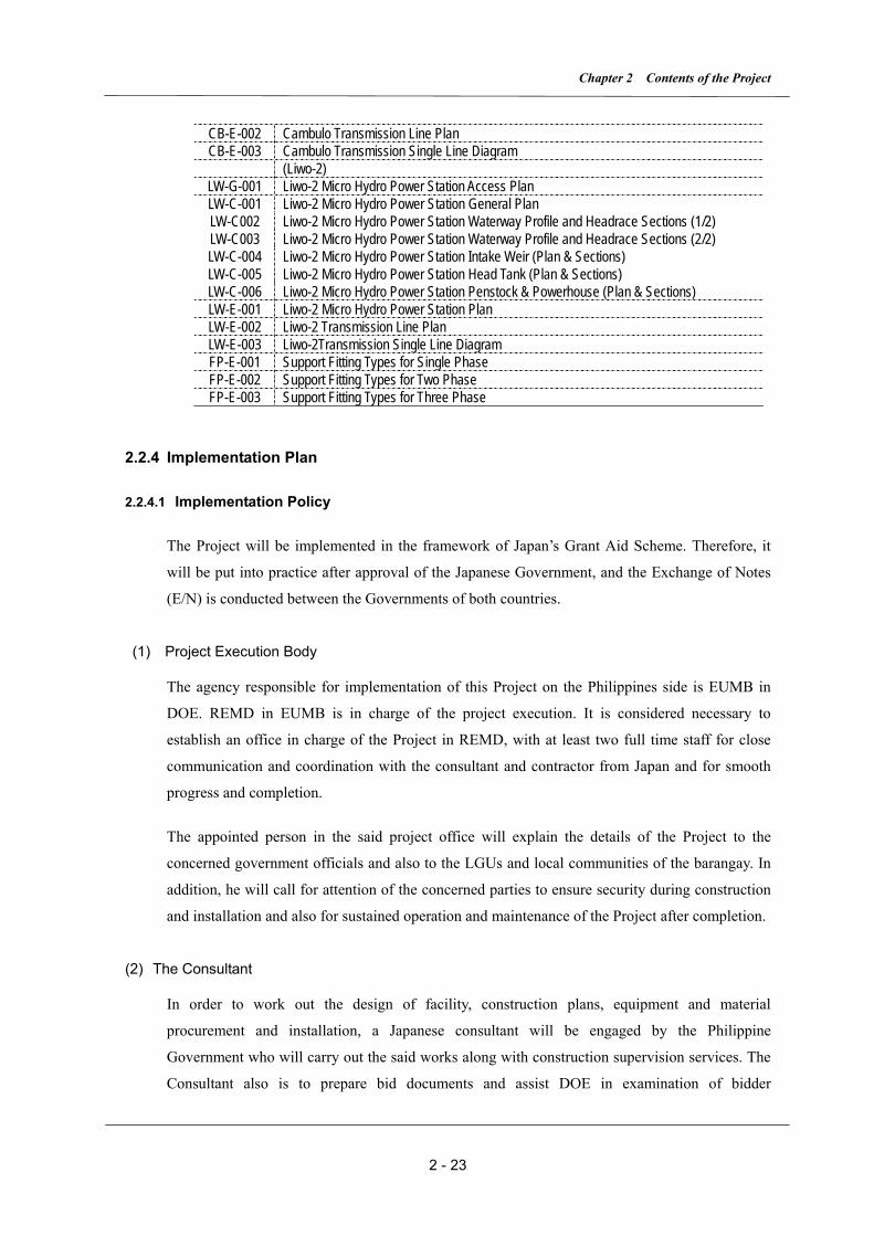
CB-E-002 Cambulo Transmission Line Plan CB-E-003 Cambulo Transmission Single Line Diagram
(Liwo-2) LW-G-001 Liwo-2 Micro Hydro Power Station Access Plan LW-C-001 Liwo-2 Micro Hydro Power Station General Plan LW-C002 Liwo-2 Micro Hydro Power Station Waterway Profile and Headrace Sections (1/2) LW-C003 Liwo-2 Micro Hydro Power Station Waterway Profile and Headrace Sections (2/2) LW-C-004 Liwo-2 Micro Hydro Power Station Intake Weir (Plan & Sections) LW-C-005 Liwo-2 Micro Hydro Power Station Head Tank (Plan & Sections) LW-C-006 Liwo-2 Micro Hydro Power Station Penstock & Powerhouse (Plan & Sections) LW-E-001 Liwo-2 Micro Hydro Power Station Plan LW-E-002 Liwo-2 Transmission Line Plan LW-E-003 Liwo-2Transmission Single Line Diagram FP-E-001 Support Fitting Types for Single Phase FP-E-002 Support Fitting Types for Two Phase FP-E-003 Support Fitting Types for Three Phase
2.2.4 Implementation Plan
2.2.4.1 Implementation Policy
The Project will be implemented in the framework of Japan’s Grant Aid Scheme. Therefore, it
will be put into practice after approval of the Japanese Government, and the Exchange of Notes
(E/N) is conducted between the Governments of both countries.
(1) Project Execution Body
The agency responsible for implementation of this Project on the Philippines side is EUMB in
DOE. REMD in EUMB is in charge of the project execution. It is considered necessary to
establish an office in charge of the Project in REMD, with at least two full time staff for close
communication and coordination with the consultant and contractor from Japan and for smooth
progress and completion.
The appointed person in the said project office will explain the details of the Project to the
concerned government officials and also to the LGUs and local communities of the barangay. In
addition, he will call for attention of the concerned parties to ensure security during construction
and installation and also for sustained operation and maintenance of the Project after completion.
(2) The Consultant
In order to work out the design of facility, construction plans, equipment and material
procurement and installation, a Japanese consultant will be engaged by the Philippine
Government who will carry out the said works along with construction supervision services. The
Consultant also is to prepare bid documents and assist DOE in examination of bidder

The Project for Electrification in Northern Luzon
2 - 24
prequalification and bids.
As there are 5 subject sites in the Project, local engineers will be engaged by the Japanese
Consultant who will dispatch resident supervisors from the local engineers at each site for quality,
security and schedule control.
(3) The Contractor and Local Contractors
The Contractor will be a Japanese corporation selected by the Government of the Philippines
through competitive bidding in accordance with Japan’s Grant Aid Scheme. The Contractor
will construct facilities, procure equipment/material and install, test and commission the
equipment procured under the Project.
In order to incorporate local resources as much as possible into execution of the Project, local
construction company(s) with ample experience in the field of hydraulic civil engineering
structures, installation of transmission lines, etc. will be engaged as subcontractor(s) by the
Japanese Contractor.
(4) Necessity to Dispatch Japanese Engineers
Since the work planned under the Project consists of several major components such as civil
engineering structure construction, hydro-mechanical and electrical facilities such as gates and
penstocks, turbines, generators and control/protection equipment, construction of transmission
lines, and testing and commissioning the equipment, coordination among these components is
crucial for successful completion of the Project as a whole under the given physical and time
constraints.
Dispatch of a site manager from the Japanese Consultant in this regard is considered vital to
ensure the quality of the work, safe operation and timely completion.
2.2.4.2 Implementation Conditions
(1) Points to be Considered in Execution of the Work
As Northern Luzon is located under the route of typhoons, people suffer from disastrous damage
such as to bridges by floods and traffic disruption by landslides almost every year. As local roads,
which are a great distance from trunk national roads are not well maintained, it takes a long time
to restore the bridges and roads once they are damaged.
As the subject sites of the Project are located in the mountains and far from trunk roads, the

Chapter 2 Contents of the Project
2 - 25
equipment and materials for the Project will certainly have be transported during the season free
of typhoons, that is any time of the year except July thru October.
Equipment and materials will have to be transported by man power from the end points of
vehicular delivery along the rural roads around the barangay to the power station sites. As these
access roads run along steep mountain slopes, transportation of equipment and materials will
have to be scheduled in the dry season to ensure safety of goods as well as people. When
transportation in rainy season is unavoidable, special safety precautions must be exercised.
Even transportation of heavy equipment such as turbines, generators, transformers or over-size
equipment such as penstocks and transmission/distribution poles will have to depend on man
power to a large extent, therefore route selection and weather forecasts will have to be very
carefully done and watched.
Catchment areas of Maling-2, Maluksad and Cambulo sites are so large that there are huge
volumes of water flow in the rainy season. Construction work on such hydraulic structures as
weirs and intakes, which will be in the river water permanently after completion must be
scheduled during low river water flow periods, namely from the end of the dry season thru the
early rainy season, so that temporary water diversion works can be minimized.
To accelerate construction in the dry season, ample construction materials must have been
delivered on time at the site. That will in turn require large temporary stock yards around the
sites. Timely rescheduling to cope with sudden inclement weather or soil conditions will be
called for. These will be important tasks of the engineer dispatched from the Japanese Consultant.
When dynamite blasting, which will certainly be needed for some of the weirs, intakes and
headrace construction works, special safety measures for labors and also for the local community
will have to be exercised according to applicable safety standards and regulations in the country.
(2) Points to be Considered for Procurement
1) Equipment Design
The five Project sites are scattered in remote regions. To maintain the planned schedule, well
organized plans for procurement and transportation of equipment and materials to the sites are
very important.
Moreover, considering the fact that BAPA organized by the barangay residents will operate and
maintain the equipment after completion, the entire generating system must be simple and
trouble-free.

The Project for Electrification in Northern Luzon
2 - 26
As for the turbines and generators, the ones made in the Philippines could not be used judging
from the fact that existing micro-hydro power plants are prone to frequent malfunction. Speaking
about the equipment made in the third countries, malfunction of turbines occurred in a
micro-hydro power plant in Layte Island. After two years operation, it was replaced with ones
made in Japan. In view of these incidents, long-term reliable equipment from Japan is strongly
recommended.
On the other hand, equipment and materials for transmission and distribution lines such as
aluminum conductors, cables, poles, and transformers and mechanical assemblies such as
penstocks and gates that are available in the Philippines have satisfactory records with domestic
power companies and industries and have proven their reliability. As a consequence, these local
goods are recommended.
The Basic Design Study Team visited factories manufacturing aluminum conductors, power and
control cables during the basic design study period and confirmed that they have good
manufacturing capacity and their products meet the requirements of the Project.
2) Procurement Control
For smooth execution within the defined period of field work, it is absolutely necessary to deliver
the equipment and materials to the sites in a timely manner. Since the period of marine
transportation from Japan plus inland vehicular transportation to as near the sites as possible is
expected to be about 20 days, the Contractor must undertake procurement in advance paying due
attention to this factor. For example, all necessary documents for transportation and customs
clearance must be expertly prepared so as not to cause set backs to the progress of the Project.
3) After-sales Service
As it is necessary for the Contractor to provide after-sales service in terms of supply of spare
parts and repair of breakdowns associated with the new equipment, he must be able to keep
uninterrupted liaison with the concerned parties in the Philippines after the completion of the
Project.
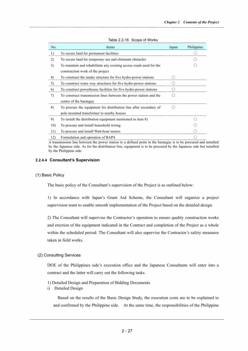
2.2.4.3 Scope of Works
Regarding the various undertakings that are necessary to implement the Project’s procurement
and installation, the Japanese and the Philippine sides are in agreement with the following
demarcations in Table 2.2-16, that are self-explanatory.
Chapter 2 Contents of the Project
2 - 27
Table 2.2-16 Scope of Works
No. Items Japan Philippine
1) To secure land for permanent facilities ○ 2) To secure land for temporary use and eliminate obstacles ○ 3) To maintain and rehabilitate any existing access roads used for the
construction work of the project ○
4) To construct the intake structure for five hydro-power stations ○ 5) To construct water way structures for five hydro-power stations ○ 6) To construct powerhouse facilities for five hydro-power stations ○ 7) To construct transmission lines between the power station and the
center of the barangay ○
8) To procure the equipment for distribution line after secondary of pole mounted transformer to nearby houses
○
9) To install the distribution equipment mentioned in item 8) ○ 10) To procure and install household wiring ○ 11) To procure and install Watt-hour meters ○ 12) Formulation and operation of BAPA ○
A transmission line between the power station to a defined point in the barangay is to be procured and installed by the Japanese side. As for the distribution line, equipment is to be procured by the Japanese side but installed by the Philippine side.
2.2.4.4 Consultant’s Supervision
(1) Basic Policy
The basic policy of the Consultant’s supervision of the Project is as outlined below:
1) In accordance with Japan’s Grant Aid Scheme, the Consultant will organize a project
supervision team to enable smooth implementation of the Project based on the detailed design.
2) The Consultant will supervise the Contractor’s operation to ensure quality construction works
and erection of the equipment indicated in the Contract and completion of the Project as a whole
within the scheduled period. The Consultant will also supervise the Contractor’s safety measures
taken in field works.
(2) Consulting Services
DOE of the Philippines side’s execution office and the Japanese Consultants will enter into a
contract and the latter will carry out the following tasks.
1) Detailed Design and Preparation of Bidding Documents i) Detailed Design
Based on the results of the Basic Design Study, the execution costs are to be explained to
and confirmed by the Philippine side. At the same time, the responsibilities of the Philippine
The Project for Electrification in Northern Luzon
2 - 28
side are to be confirmed for timely work execution. Prior to the preparation of bidding
documents, detailed design will be performed, the execution cost precisely estimated and
construction plans worked out.
ii) Preparation of Bidding Documents
The bidding documents will be prepared based on the results of the detailed design and the
construction plans conforming to the requirements of the Grand Aid Scheme.
2) Procurement and Construction Supervision i) Bidding Process
The process includes the bid calling, questions and answers, attendance to bid closing and
opening, evaluation of bids, assistance in negotiation and conclusion of execution contract.
ii) Site Supervision Process
This process comprises meetings among concerned parties before commencing site works,
approval of shop drawings, factory inspection before shipment, supervision of site erection
works, preparation of progress reports during site construction, issue of interim certificates,
and attendance to site tests before taking over.
iii) Process after Completion of Construction and Erection
This process comprises issue of completion certificates, processing for taking over,
preparation of completion reports and defect liability tests to be carried out one year after
taking over.
(3) Members of the Consultant
To smoothly execute the necessary services itemized in Item (2), it is required that a senior
engineer with ample experience in similar kinds of services and full understanding of the
contents of the Project will be nominated as Project Manager and an effective organization
consisting of staffs for detailed design, bidding procedures, review and approval of design,
factory inspection, and site supervision will be established.
1) Members for Detailed Design
Table2.2-17 Members for Detailed Design
Title Contents of Assigned Work Project Manager Based on full understanding of the background and purposes of the Project, the Project
Manager will manage the overall execution of the Project. He will review and monitor progress of the Project and current problems, control the work progress, and instruct and provide advice to subordinate members. He will carry out bid calling, questions and answers, bid acceptance, evaluation of submitted bids, and assist negotiation and conclusion of contract
Engineers for Civil Facility Design A and B
Based on the established basic design criteria, engineers will determine specifications of civil engineering structures, detailed design, drawings for the five micro-hydropower plants taking into account the natural and physical constraints. Engineer A will carry out bid calling, questions and answers, bid acceptance, evaluation of

Chapter 2 Contents of the Project
2 - 29
submitted bids, and assist with negotiations and conclusion of contract Engineer for Gates and Penstock
Based on the established basic design criteria, the engineer will determine the specifications for the Gates and Penstock and execute the detailed design and drawings for the five micro-hydropower plants taking into account natural and physical constraints.
Engineer for Turbine and Generator
Based on the established basic design criteria, the engineer will determine the specifications for the Turbine and Generator, and execute the detailed design for the five micro-hydropower plants taking into account natural and physical constraints.
Engineers for Transmission/ Distribution Line A and B
Based on the established basic design criteria, these engineers will determine the specifications for the Transmission/ Distribution Line, and execute the detailed design, drawings for the five micro-hydropower plants taking into account the natural and physical constraints. As for the distribution line, Quantity of the material to be procure will be checked through site surveys.
Engineer for Construction Program/ Cost Estimate (Civil)
Based on the established basic design, the engineer will prepare the construction schedule and estimate the project cost for the five micro-hydropower plants taking into account the natural and physical constraints based on necessary data from each engineer
Engineers for Bidding Documents
An engineer will collect the required technical information from each engineer and prepare the bidding documents for the five micro-hydropower plants.
2) Members for Construction Supervision
Table 2.2-18 Members for Construction Supervision
Title Contents of Assigned Work Chief Engineer for Site Supervision
Based on a full understanding of the background and purposes of the Project, the Chief Engineer will manage the overall execution of the Project. He will review and monitor the progress of the project and current problems, control the progress of the works, and instruct and provide advice to subordinate members. He will support training for formation, operation and management of BAPA and assist to establish a supporting system in cooperation with Technical Cooperation Project in order to enhance BAPA.
Resident Engineer for Civil Facilities
The resident supervising engineer will supervise the entire site works from commencement of construction up to completion of the Project (5 micro-hydropower plants).
Engineer for Civil Facilities
The civil engineer will supervise the civil and building works for the micro-hydropower plants and will be dispatched to the site to perform necessary supervision services during the dry season.
Gates and Penstock Engineer
The Gates and Penstock engineer will be in charge of drawing approval, fabrication, factory inspection and site tests, and installation of gates and penstocks for the micro-hydropower plants and will be dispatched to the site to perform necessary supervising works.
Inspector for Turbines and Generators
The Inspector will examine Turbines and Generators drawings for which Contractor apply for approval and check the quality and function of the equipment at factory prior to the shipment.
Inspector for Transmission/Distribution Line
The Inspector will examine Transmission/Distribution Line facilities’drawings for which Contractor apply for approval.
Procurement Engineer
Procurement Engineer will assist to take over constructed facilities as completion.
Procurement Management Engineer for Turbines and Generators
The electrical engineer will be in charge of turbines, generators, control devices and electrical facilities for the five micro-hydropower plants and will be dispatched to the site to perform necessary supervising works.
Procurement Management Engineer for Transmission/Distribution Line
The engineer in charge of high voltage transmission and distribution line facilities for the five micro-hydropower plants will be dispatched to the site to perform necessary supervising works
Operation Examiner
During commissioning of the facilities, the examiner will operate, examine and test whole facilities.
The Project is unique in that transmission line extension is prohibitive. However, there is
great difficulty to access the sites where even cell phones can not be used. The only
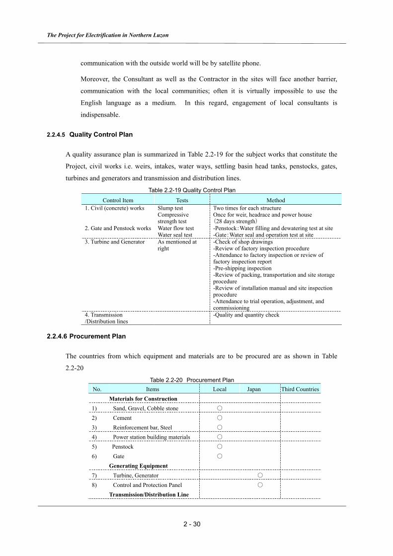
The Project for Electrification in Northern Luzon
2 - 30
communication with the outside world will be by satellite phone.
Moreover, the Consultant as well as the Contractor in the sites will face another barrier,
communication with the local communities; often it is virtually impossible to use the
English language as a medium. In this regard, engagement of local consultants is
indispensable.
2.2.4.5 Quality Control Plan
A quality assurance plan is summarized in Table 2.2-19 for the subject works that constitute the
Project, civil works i.e. weirs, intakes, water ways, settling basin head tanks, penstocks, gates,
turbines and generators and transmission and distribution lines.
Table 2.2-19 Quality Control Plan
Control Item Tests Method 1. Civil (concrete) works Slump test
Compressive strength test
Two times for each structure Once for weir, headrace and power house (28 days strength)
2. Gate and Penstock works Water flow test Water seal test
-Penstock:Water filling and dewatering test at site -Gate:Water seal and operation test at site
3. Turbine and Generator As mentioned at right
-Check of shop drawings -Review of factory inspection procedure -Attendance to factory inspection or review of factory inspection report -Pre-shipping inspection -Review of packing, transportation and site storage procedure -Review of installation manual and site inspection procedure -Attendance to trial operation, adjustment, and commissioning
4. Transmission /Distribution lines
-Quality and quantity check
2.2.4.6 Procurement Plan
The countries from which equipment and materials are to be procured are as shown in Table
2.2-20
Table 2.2-20 Procurement Plan No. Items Local Japan Third Countries Materials for Construction 1) Sand, Gravel, Cobble stone ○ 2) Cement ○ 3) Reinforcement bar, Steel ○ 4) Power station building materials ○ 5) Penstock ○ 6) Gate ○ Generating Equipment 7) Turbine, Generator ○ 8) Control and Protection Panel ○ Transmission/Distribution Line

Chapter 2 Contents of the Project
2 - 31
9) Steel Poles ○ 10) Wire, Cable ○ 11) Transformer, Switchgear ○
2.2.4.7 Operational Guidance Plan
Operation and maintenance of the Project facilities after completion are to be undertaken by
BAPA as the recipient of facilities and they are to play a vital roll in the post project period. It is
indispensable that they are assisted by LGUs and monitored by DOE.
In the event of getting approval of the Project, it is quite important that BAPA cooperate with the
on-going Technical Cooperation Program to obtain guidance from it to work out his own
practical and appropriate organization and rules of operation. The Program is also expected to
afford appropriate advice and guidance to BAPA throughout the construction period of the
Project.
As regards the technical aspect, it is unlikely that hydro-electric engineers are resident in any of
the local communities. Therefore, to counter an emergency such as electric trouble or turbine
generator related accident it is essential that the local government has established a supporting
service system from a regional power utility company for such cases.
In order for BAPA to conduct smooth management of the power supply, there is a common issue
to tackle, that is, each local community must pay its power tariff regularly and fully and
collection and expending the money is to be conducted in a transparent accounting system. As
there is a considerable disparity in income among the residents of the barangays and sitios where
some of them are substantially poorer than the others, it may be crucial to establish a practical
and well balanced tariff system based on these existing conditions.

The Project for Electrification in Northern Luzon
2 - 32
2.2.4.8 Implementation Schedule
Execution of this Project will require 20 months from the conclusion of the Exchange of Notes
up to completion. The Exchange of Notes will cover both detailed design service and project
construction and installation. Table 2.2-21 shows the overall Implementation Time Schedule.
Table 2.2-21 Implementation Schedule
Month 14 154 13128 95 6 22321 222010 11
Det
aile
d D
esig
n an
d B
bidd
ing
2 19181716731
Proc
urem
ent a
nd In
stal
latio
nC
ivil
Wor
ks
(Site Survey)
(Detailed Design)
(Preparation of Bidding Documents)
(Bidding)
(Bid Evaluation and Contracting)
(Approval of Drawings)
(Manufacture)
(Factory Test and Pre-ship Inspection)
(Transportation)
(Comissioning and Takingover)
(Preparation and Temporary Works)
(Civil Works)
(Turbine and Generator InstallationWorks)
(Home Work)
(Site Work)
Legend
(Total 6.0 Months)
(Material and Equipment Transportation)
(Maling-1)
(Maling-2)
(Maluksad)
(Cambulo)
(Liwo-2)
(Transmission Line Works)
(Total 13.0 Months)
(Civil Works)
(Civil Works)
(Civil Works)
(Civil Works)
(Total 14.0 Months)
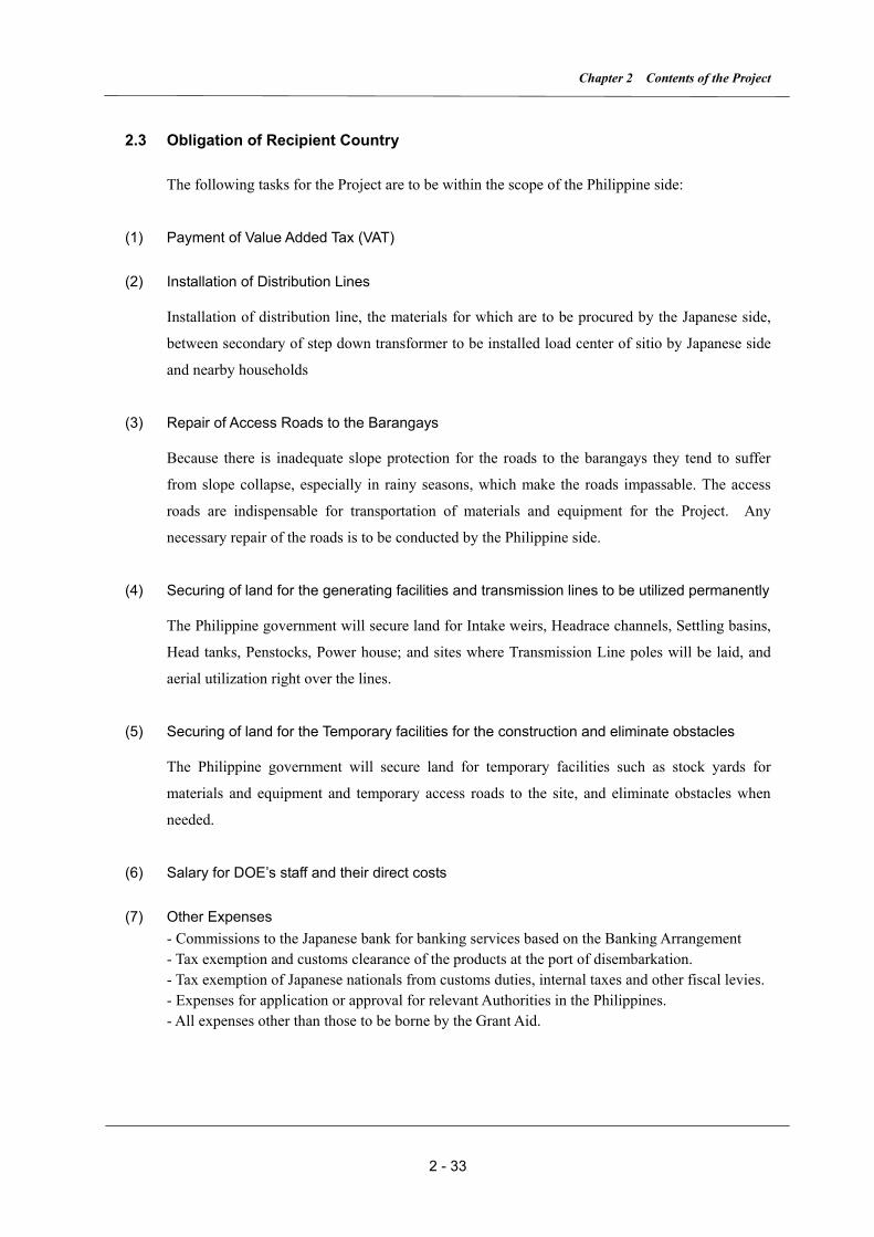
Chapter 2 Contents of the Project
2 - 33
2.3 Obligation of Recipient Country
The following tasks for the Project are to be within the scope of the Philippine side:
(1) Payment of Value Added Tax (VAT)
(2) Installation of Distribution Lines
Installation of distribution line, the materials for which are to be procured by the Japanese side,
between secondary of step down transformer to be installed load center of sitio by Japanese side
and nearby households
(3) Repair of Access Roads to the Barangays
Because there is inadequate slope protection for the roads to the barangays they tend to suffer
from slope collapse, especially in rainy seasons, which make the roads impassable. The access
roads are indispensable for transportation of materials and equipment for the Project. Any
necessary repair of the roads is to be conducted by the Philippine side.
(4) Securing of land for the generating facilities and transmission lines to be utilized permanently
The Philippine government will secure land for Intake weirs, Headrace channels, Settling basins,
Head tanks, Penstocks, Power house; and sites where Transmission Line poles will be laid, and
aerial utilization right over the lines.
(5) Securing of land for the Temporary facilities for the construction and eliminate obstacles
The Philippine government will secure land for temporary facilities such as stock yards for
materials and equipment and temporary access roads to the site, and eliminate obstacles when
needed.
(6) Salary for DOE’s staff and their direct costs
(7) Other Expenses - Commissions to the Japanese bank for banking services based on the Banking Arrangement - Tax exemption and customs clearance of the products at the port of disembarkation. - Tax exemption of Japanese nationals from customs duties, internal taxes and other fiscal levies. - Expenses for application or approval for relevant Authorities in the Philippines. - All expenses other than those to be borne by the Grant Aid.
The Project for Electrification in Northern Luzon
2 - 34
2.4 Project Operation Plan
After completion of the Project, to ensure uninterrupted operation and maintenance of the
facilities, the following measures are expected to be implemented:
(1) Cooperation on the Project Execution by the Local Communities
Since residents of the selected barangays for the Project will play an important role in the
management, operation and maintenance, their firm commitment to the Project is increasingly
important. In this regard, effort was strenuously made to confirm this aspect during the site
surveys by the Basic Design Study Team. In order to implement this Project smoothly,
cooperation from barangay residents should be afforded to the construction and installation
parties as well, especially installation of the hydro-electric equipment and transmission lines will
need their understanding during the construction periods.
(2) Establishment of O&M Framework
(a) Cooperation with On–going Technical Cooperation Team
It is actually impossible for the local residents to envisage the concept and process of the
Project implementation through detailed design and to make themselves ready for actual
operation and maintenance activities. So cooperation with the on-going Technical Cooperation
Project Team is very much encouraged.
(b) Appropriate Income and Power Tariff
In order to ensure sustainable operation, BAPA has to depend on the power tariff as the major
source of income. The power tariff needs be determined in consideration of the required
expenditures and income levels of each barangay. BAPA shall conduct fair and transparent
accounting and report to the users.
(c) Formulation of BAPA and Drafting the Articles of Incorporation
On formulating BAPA, the articles of incorporation and supply terms and conditions have to
be drafted.
(3) Cooperation from DOE and LGU
(a) Dispatching DOE to Initial Technical Transfer Training
It is quite unlikely that there are any electrical engineers resident in any of the barangays.
Chapter 2 Contents of the Project
2 - 35
Consequently, at the initial stage, participation in the training programs from DOE and LGU is
considered mandatory.
(b) Financial Assistance from DOE and LGU
BAPA will have to allocate some portion of the collected tariff for maintenance purposes. As a
matter of fact, it is actually impossible for them to bear the entire cost of expensive spare parts
for repair and maintenance. As a result, it is recommended that a loan system from DOE or LGU
for costly spare parts be established.
(4) Acquisition of Operation and Maintenance Skill
(a) Participation by the barangay residents in on-the-job training from the construction stage
It is recommended that participation in on-the-job training offered by the Contractor in order to
acquire operation and maintenance skill should be an obligation for concerned residents. This
training could consolidate commitment to the Project and also enhance the sense of belonging to
the electrified communities, and eventually lead to smooth implementation of the Project.
(b) Guidance service contract with equipment suppliers or manufacturers
It is recommended that a guidance service contract be made between BAPA and the
manufacturers because overhaul work if needed is difficult to be carried out by BAPA on their
own.
2.5 Project Cost Estimation
2.5.1 Initial Cost Estimation
Cost estimate in the Basic Design Study will be shown in the event of the Exchange of Notes
provided that this Project will be implemented under a Japanese Grant Aid Scheme. Based on
the conditions mentioned in paragraph (2), estimated cost to be borne by the Japanese side is
shown in Annex -4 of Appendix 5.
This cost estimate is provisional and will be further examined by the Government of Japan for
the approval of the Grant.

The Project for Electrification in Northern Luzon
2 - 36
(1) Estimate of Cost to be Borne by the Philippine Side
1) VAT (Value Added Tax) Php 34.3 mil. (App. 83.8 mil. Yen)
2) Installation cost of distribution line Php 2.2 mil. (App. 5.4 mil. Yen)
3) Maintenance of road side walls and access Php 1.3 mil. (App. 3.2 mil. Yen)
roads to sites
4) Secure land Php 0.4 mil. (App. 1.0 mil. Yen)
5) Removal of existing trees, etc. Php 0.2 mil. (App. 0.5 mil. Yen)
6) Transportation expense of DOE staff Php 0.5 mil. (App. 1.2 mil. Yen)
7) B/A and A/P (0.1% of Expenditure) Php 0.3 mil. (App. 0.7 mil. Yen)
Total Php 39.2 mil. (App. 95.8 mil. Yen)
(2) Estimating Conditions
1) Date of Estimate: December, 2006
2) Exchange Rate: 1 US$ = 117.55Yen、1Php=2.44Yen
3) Period of Construction: Detailed design and period of construction are shown in Table
2.2-21
4) Others: The Project will be implemented under a Japanese Grant Aid Scheme.
2.5.2 Operation and Maintenance Cost
The barangay residents have no experience managing the power generation or distribution related
work of the Project sites because these sites have not been electrified so far.
Given that this Project is being implemented under a Japanese Grant Aid Scheme, initial
investment by the residents in the micro hydro-electric facilities is not necessary. But to
permanently manage the power generation and distribution business, it is recommended that a
system to save money be established for renewal of the facilities after the current Project’s life
has lapsed. The activity to build a framework in this aspect is one of the important on-going
undertakings of the Technical Assistance Team.
Table2.5-1 Items of Major Expenditure
Items for Major Expenditure
1) Allowance for BAPA executives 2) Labor cost (Operator、Tariff collector、Patrol staff) 3) Cost to purchase spare parts and maintenance cost 4) Reserved fund for newel of facilities 5) Expenses on office 6) Other (Savings、expenses to purchase batteries)
It is natural that the various Project sites will have different tariff rates because each site has a
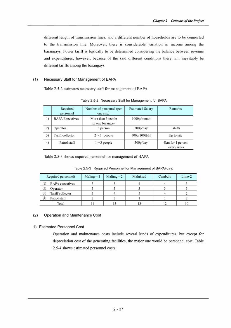
Chapter 2 Contents of the Project
2 - 37
different length of transmission lines, and a different number of households are to be connected
to the transmission line. Moreover, there is considerable variation in income among the
barangays. Power tariff is basically to be determined considering the balance between revenue
and expenditures; however, because of the said different conditions there will inevitably be
different tariffs among the barangays.
(1) Necessary Staff for Management of BAPA
Table 2.5-2 estimates necessary staff for management of BAPA
Table 2.5-2 Necessary Staff for Management for BAPA
Required personnel
Number of personnel (per one site)
Estimated Salary Remarks
1) BAPA Executives More than 3people in one barangay
1000p/month
2) Operator 3 person 200p/day 3shifts
3) Tariff collector 2~5 people 500p/100H/H Up to site
4) Patrol staff 1~3 people 300p/day 4km for 1 person every week
Table 2.5-3 shows required personnel for management of BAPA
Table 2.5-3 Required Personnel for Management of BAPA(day)
Required personnel) Maling-1 Malimg-2 Maluksad Cambulo Liwo-2
① BAPA executives 3 3 4 4 3 ② Operator 3 3 3 3 3 ③ Tariff collector 3 4 5 4 2 ④ Patrol staff 2 3 1 1 2
Total 11 13 13 12 10
(2) Operation and Maintenance Cost
1) Estimated Personnel Cost
Operation and maintenance costs include several kinds of expenditures, but except for
depreciation cost of the generating facilities, the major one would be personnel cost. Table
2.5-4 shows estimated personnel costs.
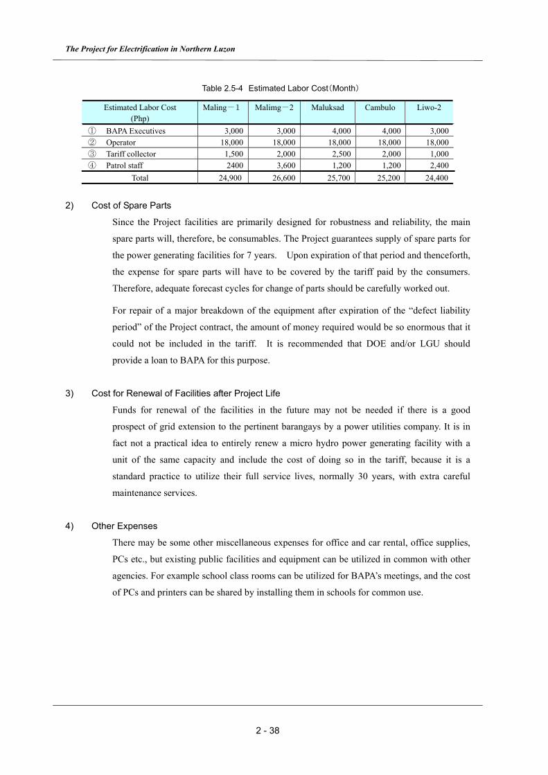
The Project for Electrification in Northern Luzon
2 - 38
Table 2.5-4 Estimated Labor Cost(Month)
Estimated Labor Cost (Php)
Maling-1 Malimg-2 Maluksad Cambulo Liwo-2
① BAPA Executives 3,000 3,000 4,000 4,000 3,000 ② Operator 18,000 18,000 18,000 18,000 18,000 ③ Tariff collector 1,500 2,000 2,500 2,000 1,000 ④ Patrol staff 2400 3,600 1,200 1,200 2,400
Total 24,900 26,600 25,700 25,200 24,400
2) Cost of Spare Parts
Since the Project facilities are primarily designed for robustness and reliability, the main
spare parts will, therefore, be consumables. The Project guarantees supply of spare parts for
the power generating facilities for 7 years. Upon expiration of that period and thenceforth,
the expense for spare parts will have to be covered by the tariff paid by the consumers.
Therefore, adequate forecast cycles for change of parts should be carefully worked out.
For repair of a major breakdown of the equipment after expiration of the “defect liability
period” of the Project contract, the amount of money required would be so enormous that it
could not be included in the tariff. It is recommended that DOE and/or LGU should
provide a loan to BAPA for this purpose.
3) Cost for Renewal of Facilities after Project Life
Funds for renewal of the facilities in the future may not be needed if there is a good
prospect of grid extension to the pertinent barangays by a power utilities company. It is in
fact not a practical idea to entirely renew a micro hydro power generating facility with a
unit of the same capacity and include the cost of doing so in the tariff, because it is a
standard practice to utilize their full service lives, normally 30 years, with extra careful
maintenance services.
4) Other Expenses
There may be some other miscellaneous expenses for office and car rental, office supplies,
PCs etc., but existing public facilities and equipment can be utilized in common with other
agencies. For example school class rooms can be utilized for BAPA’s meetings, and the cost
of PCs and printers can be shared by installing them in schools for common use.


Chapter 3 Project Evaluation and Recommendations
3 - 1
Chapter 3 Project Evaluation and Recommendations
3.1 Project Effects
(1) Direct Effects
By implementing the Project, 1,600 households with a total population of 8,000 in ten (10)
barangays will be supplied with electric power. The total output of electric power is planned to
be 334 kW from the five power plants, and power of 200W can be allocated to each household
for 24 hours a day throughout the year.
(2) Indirect Effects
The following indirect effects are expected by implementing the Project.
1) Poverty Reduction
Utilization of electric power by local residents will enable introduction of electric equipment
such as threshing machine for farming that will increase their income and eventually lead to
poverty reduction in rural communities.
2) Improvement of Educational Environment
Electric lighting at home would enable children to study in the evening that will improve
educational environment.
3) Improvement of Living Environment
Access to and TV and radio will be made possible by the electrification, which will give access
to real time information networks, to say nothing of the electric home appliances such as
washing machines, refrigerators etc.. The living environment of the rural communities will
be greatly modernized.
4) Formulation of BAPA
A model of BAPA is expected to be formalized

The Project for Electrification in Northern Luzon
3 - 2
3.2 Recommendations
3.2.1 Recommendations
In order to realize the foregoing effects through uninterrupted and sustained operation of the
Project facilities, it is recommended that the Philippines side tackles the following issues in a
timely manner.
1) It is very important to set forth a suitable power tariff system taking the actual resident’s
livelihood into consideration. No less important, however, is to collect the full power tariff
from the residents and without delay to enable smooth and sustained operation and
maintenance of the Project facilities.
2) The operators and maintenance staff as well as accountants and administrators should not
fail to participate in the training programs given by the Project to acquire as much
knowledge and skill as possible for the Project facilities. It should be ensured that these
people thereafter are actually engaged in their respective jobs after commissioning of the
facilities.
3) DOE staff and relevant LGUs should be engaged in technical and financial assistance for
BAPA on their own outside the scope of the Project
4) The operators and maintenance staff and accounting and administrative personnel should
continue to participate in the training programs that will be conducted in the future in an
effort to improve their own skills.
5) BAPA will have to report to LGUs, and LGUs in turn should monitor their activities and
provide appropriate guidance and advice. In case of need, LGUs should support them in
technical and financial matters.
6) The concerned offices of the Philippine government should give appropriate technical and
financial support to the residents of BAPA whenever they attempt to improve their
livelihoods.
3.2.2 Cooperation with Technical Assistance
Operation and maintenance of the Project facilities after completion are to be undertaken by
BAPA (Barangay Alternative Power Association), which are composed of the local residents who
are the recipient of the facilities. The BAPA play a vital roll in the post project period. It is
indispensable that they are assisted by LGUs and monitored by DOE. Part of the Project is to
assist to establish BAPA by March 2008 in collaboration with an on-going Technical Cooperation
Program Team. It is planned that BAPA will cooperate with the Team to obtain guidance to

Chapter 3 Project Evaluation and Recommendations
3 - 3
develop its own practical and appropriate organization and rules of operation. The Program is
also expected to afford appropriate advice and guidance to BAPA throughout the construction
period of the Project.