Embed Size (px)
Citation preview
Department of electronics GOVERNMENT SCIENCE COLLEGE
(Autonomous) HASSAN – 573 201
Academic year 2016 – 2017 onwards
Syllabus of B.Sc. Electronics

CONTENTS
Sl. No. Particulars
1. Subjects & Paper Code
2. Scheme of Examination
3. Scheme of IA Marks Distribution
4. Question Paper Pattern – Marks Distribution
5. Scheme of Practical Examination Marks Distribution
SYLLABUS
6. I Semester
7. II Semester
8. III Semester
9. IV Semester
10. V Semester
11. VI Semester
12. MODEL QUESTION PAPER
S emes t er , Pap er co d e and T i t l e o f Th eory and Pra ct i ca l
Semester
Code
Title of the Subject – Theory
Code
Title of the Subject -
Practical
I ELT 1.0 Basic Electronics and Network
Theorems ELP 1.0
Basic Electronics and Network
Theorems Lab
II ELT 2.0 Analog Electronic Circuit Design ELP 2.0 Amplifiers and Oscillators Lab
III ELT3.0 Digital Circuit Design ELP 3.0 Digital Circuit Design Lab
IV ELT4.0 Linear ICs ELP 4.0 Linear ICs Lab
V
ELT5.1 Microcontroller ELP 5.1 Microcontroller Lab
ELT5.2.1* VHDL ELP 5.2.1* VHDL Lab
ELT5.2.2* Microprocessor 8086 and
interfacing ELP 5.2.2* 8086 programs
VI
ELT6.1 Electronic Communication ELP 6.1 Communication Lab
ELT6.2.1* Digital Signal Processing ELP 6.2.1* Digital Signal Processing
ELT6.2.2* Biomedical Instruments, VLSI
and Robotics ELP 6.2.2* Project work
* Elective papers

Scheme of Examination
Sem Paper Code Title of
the Paper
Duration
in Hours
Marks
IA
Marks
Exam
Marks
Total Th Pr Exam Th Pr Th Pr
I I EL 1.0
Basic
Electronics and
Network
Theorems
3 3 3 30 15 70 35 150
II II EL 2.0
Analog
Electronic
Circuit Design
3 3 3 30 15 70 35 150
III III ELT3.0 Digital Circuit
Design 3 3 3 30 15 70 35 150
IV IV ELT4.0 Linear ICs 3 3 3 30 15 70 35 150
V
5 ELT5.1 Microcontroller 3 3 3 30 15 70 35 150
6 ELT5.2.1* VHDL 3 3 3 30 15 70 35 150
6 ELT5.2.2*
Microprocessor
8086 and
interfacing
3 3 3 30 15 70 35 150
VI
7 ELT6.1 Electronic
Communication 3 3 3 30 15 70 35 150
8 ELT6.2.1* Digital Signal
Processing 3 3 3 30 15 70 35 150
8 ELT6.2.2*
Biomedical
Instruments,
VLSI and
Robotics
3 3 3 30 15 70 35 150

Scheme of IA marks Distribution
IA Marks - Theory
A. Semesters I, II, III, IV, V & VI
(i) COMPONENT 1 = 15 Marks
(ii) COMPONENT 2 = 15 Marks
COMPONENT 1 Best out of TWO tests
COMPONENT 2 SEMINARS/PROJECTS/QUIZ/ASSIGNMENTS
IA = COMPONENT 1 + COMPONENT 2 = 30 Marks
IA Marks - Practical
Semester I, II, III, IV, V & VI
Practical internal test – 10 Marks + Evaluation of Practical Records – 5 Marks
15 Marks

Question Paper Pattern – Marks Distribution
1. SEMESTERS I, II, III, IV, V & VI
There will be four Parts A, B, C and D.
Part A is from Unit 1, Part B is from Unit 2 and Part C is from Unit 3.
Part D is Conceptual question
Part A, B, C each is 22 Marks and Conceptual is for 04 Marks
Total 22 + 22 + 22 + 04 = 70 Marks
PART A, B and C
Each Part Marks Distribution
1. 2 mark questions – Total 4 To be answered 3 2 × 3 = 6 marks
2. 6 mark questions – Total 3 To be answered 2 6 × 2 = 12 marks
3. 4 mark problems – Total 3 To be answered 1 4 × 1 = 4 marks
4. 2 mark questions (Conceptual) – Total 3, To be answered 2, 2 × 2 = 4 marks
Each Part: Total = 22 x 3 = 66 Marks + 4 Marks (Conceptual) = 70 Marks
A conceptual question to be asked from each unit is 1 question. Answer any two
out of 3 questions.
[Grand Total (A + B + C + D (Conceptual)) 70 marks]

Scheme of Practical Examination marks Distribution
Sem Paper Title of the
Paper
Marks Distribution Total
Marks Subdivision Marks
I I
Basic Electronics
and
Network
Theorems
1. Formula
2. Circuit diagram
3. Tabular column and or Nature of graph
4. Circuit connections
5. Taking readings
6. Calculation, graph, result, accuracy, unit
7. Viva
02
04
04
06
06
04
05
30
II II
Analog
Electronic
Circuit Design
III III Digital Circuit
Design
1. Logic/Circuit diagram
2. Truth table(s)/Tabular column(s)
3. Pin-out diagram(s) of IC(s)
4. Circuit connections
5. Taking readings
6. Result
7. Viva
05
05
05
05
05
05
05
35
IV IV Linear ICs
1. Formula
2. Circuit diagram
3. Tabular column and or Nature of graph
4. Circuit connections
5. Taking readings
6. Calculation, graph, result, accuracy, unit
7. Viva
02
04
04
07
08
05
05
35
V
5 Microcontroller
1. Writing the program
2. Working with data
3. Loading the program
4. Executing the program
5. Verifying the result
6. Viva
10
05
05
05
05
05
35
6 VHDL
1. Writing the program
2. Loading the program
3. Executing the program
4. Verifying the result
5. Viva
10
05
10
05
05
35
6
Microprocessor
8086 and
interfacing
1. Writing the program
2. Working with data
3. Loading the program
4. Executing the program
5. Verifying the result
6. Viva
10
05
05
05
05
05
35
VI 7 Electronic
Communication
1. Formula
2. Circuit diagram
3. Tabular column and or Nature of graph
4. Circuit connections
5. Taking readings
6. Calculation, graph, result, accuracy, unit
7. Viva
02
04
04
07
08
05
05
35

8 Digital Signal
Processing
1. Writing the program
2. Working with data
3. Loading the program
4. Executing the program
5. Verifying the result
6. Viva
10
05
05
05
05
05
35
8
Biomedical
Instruments,
VLSI and
Robotics
1. Design, fabrication & assembling
2. Project Report
3. Viva
20
10
05
35

Question Paper Pattern – Marks Distribution
Sem Paper
Part A
Unit 1
Part B
Unit 2
Part C
Unit 3
Part D
Unit (1+2+3)
Total Marks
Question Numbers Question Numbers Question Numbers Question Numbers
1
a,b,c,d
2
a,b,c
3
a,b,c
4
a,b,c,d
5
a,b,c
6
a,b,c
7
a,b,c,d
8
a,b,c
9
a,b,c
10
a, b, c
2
Marks
6
Marks 4 Marks
2
Marks 6 Marks 4 Marks
2
Marks 6 Marks 4 Marks 2 Marks (conceptual)
I 1 3/4 2/3 1/3 3/4 2/3 1/3 3/4 2/3 1/3 2/3 70
II 2 3/4 2/3 1/3 3/4 2/3 1/3 3/4 2/3 1/3 2/3 70
III 3 3/4 2/3 1/3 3/4 2/3 1/3 3/4 2/3 1/3 2/3 70
IV 4 3/4 2/3 1/3 3/4 2/3 1/3 3/4 2/3 1/3 2/3 70
V
5 3/4 2/3 1/3 3/4 2/3 1/3 3/4 2/3 1/3 2/3 70
6 3/4 2/3 1/3 3/4 2/3 1/3 3/4 2/3 1/3 2/3 70
VI
7 3/4 2/3 1/3 3/4 2/3 1/3 3/4 2/3 1/3 2/3 70
8 3/4 2/3 1/3 3/4 2/3 1/3 3/4 2/3 1/3 2/3 70


B.Sc. I SEMESTER
(Basic Electronics and Network Theorems)
CODE: ELT 1.0 Total teaching hours: 45 hours
Hours/week: 3hours Examination Marks: 70
UNIT 1
Electronic passive components, DC and AC analysis:
Classification of components: Passive and active components – Definition and examples.
Switches–SPST, SPDT, DPST and DPDT, fuse and electromagnetic relay, MCB, ELCB, and
RCCB (brief note on each).
Transient analysis of RC and RL circuits: Series RC circuit excited by DC source –
charging& discharging of a capacitor through resistor- circuit diagram, charge/voltage at any
instant during charging and discharging–equations (with derivations), graphical
representation, RC time constant, numerical problems. Series RL circuit excited by DC
source - circuit diagram, current at any instant during growth and decay–equations (with
derivations), graphical representation, RL time constant, (numerical problems).
AC applied to Series RC and RL circuits: Impedance of series RC &RL circuits (no
derivations), (numerical problems).
AC applied to Series and parallel RLC circuit (qualitative study–no derivations), series and
parallel resonance, condition for resonance, resonant frequency, band width, significance of
quality factor, (numerical problems). (15hours)
UNIT 2
Electronic active components and applications:
Construction, working and characteristics of diodes: PN junction diode, Zener diode, LED.
Rectifiers: Half wave rectifier, Full wave rectifier - centre tapped and bridge. Circuit
diagrams, working and waveforms, ripple factor & efficiency (with derivations), comparison,
(numerical problems).
Filters: Types, circuit diagram and explanation of shunt capacitor filter with waveforms.
Zener diode regulator– circuit diagram and explanation for load and line regulation,
(numerical problems).
Clippers and clampers: Construction and working – positive, negative and biased
Voltage multipliers: Construction and working - doubler and trippler.
Bipolar Junction Transistor: Construction, principle & working of NPN transistor,
terminology. Configuration – CE, CB, CC (mention only). Definition of α, β and γ and their
interrelations, leakage currents (mention only), Characteristics of a transistor in CE and CB
modes, (numerical problems).
MOSFET:Types, construction, working and characteristics of depletion type and
enhancement type MOSFET, comparison of MOSFET with BJT.
Uni-junction Transistor: Construction, working and characteristics, equivalent circuit,
intrinsic standoff ratio, relaxation oscillator – expression for frequency (no
derivation),(numerical problems). (15 hours)
UNIT 3
Circuit analysis:
Ohms law, Kirchhoff’s laws, voltage divider and current divider theorems, open and short
circuits, branch current, mesh analysis and node voltage method, T to π inter-conversion (no
derivations), Thevenin’s theorem, Norton’s theorem and inter-conversion, superposition
theorem -statements and steps involved, reciprocity theorem- statement, maximum power
transfer theorem-derivation, (numerical problems).
15hours
REFERENCE BOOKS: 1. A Text book of Electronics, R.S.Sedha, S Chand and Co., Multicolour,3
rdedition,
2012.
2. Electronic Principles , Albert Malvino& David J Bates, TMH, 7th edition-2010
3. Introductory circuit analysis, Robert Boylstead, PHI 5th edition-2010.
4. Electronic Devices and circuit theory, Robert Boylstead and Louis Nashelsky,
9th
Edition, 2013, PHI
5. Basic electronics- B.L. Theraja - S. Chand and Co. 3rd edition -2012.
6. Basic Electronics and Linear circuits, N.N. Bhargava, D.C. Kulshresta and D.C
Gupta-TMH.
7. Electronic devices, David A Bell, Reston Publishing Company/DB Tarapurwala Publ.
8. Electronic devices, applications and Integrated circuits, Mathur, Kulshreshta and
Chadha, Umesh Publications.
Practical – I
(ELP 1.0: BASIC ELECTRONICS AND NETWORK THEOREMS LAB)
(Minimum of 8 experiments of the following is to be performed)
1. Impedance measurement in RL and RC circuits.
2. Series resonance.
3. Verification of Thevenin’s theorem.
4. Verification of Super position theorem.
5. Verification of Norton’s theorem.
6. Verification of Maximum power transfer theorem.
7. V-I Characteristics of (a) PN junction diode and (b) Zener diode.
8. Half wave Rectifier – without and with shunt capacitance filter.
9. Centre tapped full wave rectifier – without and with shunt capacitance filter.
10. Zener diode as voltage regulator – load and line regulation.
11. Transistor characteristics in CE mode – determination of ri, ro and β.
12. UJT characteristics.

B.Sc. II SEMESTER
(Analog Electronic Circuit Design)
CODE: ELT 2.0 Total teaching hours: 45 hours
Hours/week: 3 hours Examination Marks: 70
UNIT – 1
Transistor Biasing and Small signal amplifiers:
Transistor biasing – need for biasing, DC load line, operating point, thermal runaway,
stability and stability factor (with derivation for CE mode).
Different types of biasing – Fixed bias (base bias) without and with RE, voltage divider bias
and emitter bias (+VCC and –VEE bias) –circuit diagrams and their working, Q point
expressions with numerical problems.
Transistor as a switch. Darlington pair and its applications (mention only).
Small Signal Amplifiers: H – parameters, Classification of amplifiers based on different criteria, small signal CE
amplifier – circuit, working, frequency response, Gain in decibel, Bandwidth, remodel for CE
configuration, derivation for Av, expressions for Zin and Zout. Numerical problems on Av, Zin
and Zout, Numerical problems. (15 hours)
UNIT 2
Multistage, Power and Tuned Amplifiers:
Multistage amplifiers: Qualitative study of cascaded stages, overall gain of multistage
amplifier, loading effect. Numerical problems on A=A1×A2. Types of coupling-RC coupled,
transformer coupled and direct coupled (only circuit diagrams and frequency response graph,
advantages and disadvantages for each).
Power Amplifiers: Difference between voltage and power amplifier, classification of power
amplifiers: Class A, Class B, Class C and their comparisons.
Class A single ended power amplifier–working. Transformer coupled Class A power
amplifier-working, overall efficiency (with derivation). Circuit operation of complementary
symmetry class B push pull power amplifier (with derivation), crossover distortion, heat
sinks.
Tuned amplifiers: Single tuned and double tuned amplifiers-circuit diagram, working and
frequency response for each, limitations of single tuned amplifier, brief note on use of tuned
amplifiers in communication circuits. (15 hours)
UNIT 3
Oscillators and Power devices:
Concept of feedback:Positive and negative, feedback circuits – types, effect on gain, input -
output impedances (Derivations) and bandwidth (No derivation).
Classification of Oscillators, Basic principle of oscillations, Barkhausen criterion (mention).
Study of oscillators: Colpitt’s, Hartley, Phase shift, Wien bridge oscillators. Frequency and
condition for sustained oscillations (No derivations), Crystal oscillators.
Multivibrators: Monostable, Bistable and Astable multivibrators, (numerical problems).
SCR: Working, V-I characteristics, full wave controlled rectifier – derivations for average
values of load current and voltage, numerical problems.
Diac and Triac: Construction, working, characteristics and applications. (15 hours)

Practical-II
ELP 2.0: ANALOG ELECTRONIC CIRCUIT DESIGN LAB
(Minimum of 8 experiments of the following is to be performed)
1. CE Amplifier – frequency response.
2. Design of Voltage Divider Bias circuit.
3. CC amplifier – voltage gain at one frequency, input and output impedances.
4. Tuned amplifier – frequency response.
5. UJT relaxation oscillator.
6. Voltage feedback amplifier – effect on gain and bandwidth.
7. Colpitt’s oscillator.
8. Hartley oscillator.
9. Phase shift oscillator.
10. Wien bridge oscillator.
11. AstableMultivibrator.
12. MonostableMultivibrator.
REFERENCE BOOKS:
1. A Text book of Electronics, R.S.Sedha, S Chand and Co., Multicolour, 3rd
edition,
2012.
2. Electronic Principles , Albert Malvino& David J Bates, TMH, 7th edition – 2010.
3. Electronic Devices And Circuit Theory – Robert L Boylestad And Louis
Nashelsky(PHI).
4. Basic Electronics-Solid State – B L Theraja - S Chand And Company Ltd.,
5. Electronics Fundamentals and Applications – D. Chattopadhyay and P.C. Rakshit,
New Age International Publishers.
6. Basic Electronics – BernordGrob - Tata Mcgraw-Hill Publishing Company Limited,
New Delhi.
7. Basic Electronics And Linear Circuits – N NBhargava, D C Kulshreshtha And S C
Gupta, Tata McGraw-Hill Publishing Company Limited, New Delhi.
B.Sc. III SEMESTER
(Digital Circuit Design)
CODE: ELT 3.0 Total teaching hours: 45 hours
Hours/week: 3 hours Examination Marks: 70
UNIT 1
Number systems:
Binary, Octal and Hexadecimal number systems. Conversion from one system to the other.
Addition, multiplication and division in binary systems. Negative numbers. Subtraction in
binary systems – one’s and two’s complement methods.
Boolean algebra: Laws of Boolean algebra, Principle of duality, combinational logic
circuits. De-Morgan’s theorems. Simplification of Boolean expressions. Boolean expression
for logic circuits and vice versa. Universal logic gates – NAND and NOR. Realization of
basic gates from universal gates. EXOR gate. SOP and POS notations. Canonical
expressions. Conversion from SOP to POS form and vice versa. Reduction of Boolean
expressions (three/four variables with don’t care conditions) using Karnaugh maps.
Realization of simplified Karnaugh expressions with NAND and NOR gates. (15 Hours)
UNIT 2
Combinational Circuits:
Parity codes: Parity checking codes, parity checkers and generators using XOR gates.
Weighted codes: 8421, 2421, with stress on 8421, self-complementary codes.
Non weighted codes: Excess 3 code and gray code. Alphanumeric codes – ASCII, EBCDIC
codes.
Multiplexer: 16 to 1 line multiplexer, De – multiplexer: 1 to 16 demux, Encoders – 8 to 3
line, Decimal to BCD encoders. Decoders – 2 to 4 lines, 3 to 8 lines, BCD to decimal and
seven segment display decoders.
Adders and subtractors: Half adder, full adder, half subtractor, full subtractor, four bit
adder / subtractor circuit
Families of gates: TTL and CMOS gates - parameters, circuit diagram, working of NOT and
NAND gates, compatibility. (15 Hours)
UNIT 3
Sequential logic circuits: RS flip flops, clocked RS and D flip flops, JK and T flip flops, Race around condition.
Master slave JK flip flops.
Shift registers: SISO, SIPO, PISO, PIPO registers.
Counters: 3 – bit Binary ripple counter, 4 – bit Synchronous binary counter.
MOD Counters: Mod 3, mod 5 and decade counters (Design using k-map technique).
Memory: ROM – diode matrix ROM, on – chip decoding. RAM – Memory addressing –
linear addressing, matrix addressing. DRAM and SRAM, Basic memory cell (FF) – reading
from and writing into a memory unit. Programmable Logic Devices – PROM, PAL, PLA,
PLD. (15 Hours)
REFERENCE BOOKS:
1. Albert Paul Malvino and Donald P Leach, Digital principles and applications,
McGraw Hill – 4th
edition.
2. Digital Computer Design - V Rajaram& T Radhakrishnan – PHI edition– 3rd
edition.
3. Digital fundamentals – Thomas L Floyd – Pearson Edition.
4. Digital Logic & Computer Design – M Morris Mano PHI 2nd
edition
5. Digital electronics – William H Gothmann PHI 2nd
edition.
6. Digital Principles and design – Donald D Givone - Tata McGraw Hill edition.
7. Digital Systems, Principles and applications – Ronald J Tocci& Neal S Widmer – PHI
– EEE 8th
edition.
8. Fundamental of Digital Circuits – A Anand Kumar – PHI – EEE edition
9. Digital technology – Principles and Practice – Virendra Kumar – New Age
International Publishers.
10. Modern Digital Electronics - R P Jain - 2nd
edition, Tata McGraw Hill edition.
PRACTICAL: ELP3.0: DIGITAL CIRCUIT DESIGN LAB
(Minimum of 8 experiments of the following is to be performed)
1. NAND & NOR as universal gates.
2. Realization of Boolean expressions using gates.
3. Half adder and full adder.
4. Half subtractor and full subtractor.
5. Four bit parallel adder/subtractor using 7483 and 7486.
6. Binary to gray and gray to binary converter.
7. Decimal to BCD encoder and decoder.
8. Clocked RS, D Flip-flops using NAND gates.
9. Clocked JK Flip-flop using NAND gates/IC.
10. 4 –bit binary ripple up counter using IC 7476/74107.
11. Decade counter using IC 7490.
12. Study of De-Multiplexer using IC 74154.
13. Study of Multiplexer using IC 74150.

B.Sc. IV SEMESTER
(Linear ICs and applications)
CODE: ELT 4.0 Total teaching hours: 45 hours
Hours/week: 3 hours Examination Marks: 70
UNIT 1
Introduction to Operational Amplifiers (OP-AMP): Differential amplifier using transistor
– Circuit diagram and Types (Mention only), The operational amplifier, Block diagram
representation, The ideal op-amp, equivalent circuit of an op-amp, ideal voltage transfer
curve, open-loop op-amp configurations: Inverting and non-inverting amplifiers, limitations,
closed loop inverting amplifiers, op-amp parameters and their measurement, relevant
numerical problems. (15 hours)
UNIT 2
Operational amplifier applications: Summing, Subtracting, Scaling and averaging
amplifiers, Instrumentation amplifier, voltage to current and current to voltage converters,
Integrator, Differentiator, Active filters: First order and second order low-pass and high pass
Butterworth filters. Oscillators-phase shift oscillator, Wien bridge oscillator, square wave and
triangular wave generators, comparators and Schmitt trigger, relevant numerical problems.
(15 hours)
UNIT 3
Converters, regulators and Timers: Digital to Analog Converters: binary weighted resistor
type and R-2R ladder type, Analog to digital converters: successive approximation type,
clippers and clampers, Small signal Rectifiers: Half wave and Full wave rectifier
(Working),voltage regulators – fixed voltage (78XX and 79XX) and adjustable voltage
regulators (LM 317),555Timer and its applications (Astable and Monostable), relevant
numerical problems.
(15 hours)
REFERENCE BOOKS:
1. Ramakanth A Gayekwad: Op-amps and Linear Integrated circuits, 4th edition,
PearsonEducation Asia, 2002.
2. Jacob Millman and Christos C Halkias: Integrated Electronics, Tata McGraw
Hill,(Reprint) 2005.
3. Robert F Coughlin and Frederick F Driscoll: Operational Amplifiers and
LinearIntegrated Circuits, 6th Edition, Prentice-Hall of India, 2003.
PRACTICAL: ELT4.0: LINEAR ICs LAB
(Minimum of 8 experiments of the following is to be performed)
1. Measurement of op-amp parameters – offset voltage, CMRR and slew rate.
2. Inverting and non-inverting DC amplifiers.
3. Inverting and non-inverting AC amplifiers.
4. Op-amp differentiator and integrator.
5. Instrumentation amplifier.
6. Op-amp adder and subtractor.
7. Op-amp Wien-bridge oscillator.
8. Op-amp phase shift oscillator.
9. IC 555 timer as astablemultivibrator.
10. IC 555 timer as mono-stable multivibrator.
11. Inverting and non-inverting zero crossing detector.
12. Construction of regulated power supply using IC 7805 and IC 7905.
13. Current and voltage regulation using IC LM 317.
B.Sc. V SEMESTER
(Microcontroller)
CODE: ELT 5.1 Total teaching hours: 45 hours
Hours/week: 3 hours Examination Marks: 70
UNIT 1
Introduction to Microcontrollers: Introduction to microprocessors and Microcontrollers, A
microcontroller survey, (8051, PIC, ARM family), Development systems for
Microcontrollers, RISC and CISC CPU Architectures, Harvard and Von-Neumann CPU
Architecture. The 8051 Architecture: Introduction, Pin diagram and 8051 Microcontroller
architecture (INTEL), Input/Output pins, ports and circuits, External memory, Counter and
Timers, Serial Data Input/Output, Interrupts. (15 hours)
UNIT 2
8051 Addressing modes and Moving Data: Introduction, Addressing modes, external data
moves, code memory, read only data moves/Indexed addressing mode, PUSH and POPop-
codes, data exchanges, example programs.
Logical Operations, Arithmetic operations, Jump operations: Logical operations:
Introduction, byte level logical operations, bit level logical operations, rotate and swap
operations, example programs. Arithmetic operations: Introduction, flags, incrementing and
decrementing, addition, subtraction, multiplication and division, decimal arithmetic, example
programs. Jump operations: Introduction, JUMP and CALL program range, Jump calls and
Subroutines, Interrupts and Returns, More detail on Interrupts, Example programs.
(15 hours)
UNIT 3
Counter/Timer Programming in 8051: Programming 8051 Timers/Counters.
Interrupts Programming: 8051 Interrupts, Programming Timer Interrupts, Programming
External hardware Interrupts, Programming the Serial Communication Interrupts, Interrupt
Priority in the 8051.8051 Interfacing and Applications: Interfacing 8051 to ADC, DAC,
Stepper Motor, 8255, External Memory Interfacing. (15 hours)
REFERENCE BOOKS:
1. The 8051 Microcontroller Architecture, programming and applications – Kenneth
JAyala, 2nd edition, Penram International, 1996.
2. The 8051 Microcontroller and Embedded systems – Muhammed Ali Mazidi
andJanice GillispieMazidi, Pearson Education, 2003.
3. Programming and customizing the 8051 microcontroller – Predko, TMH.
PRACTICAL: ELP5.1: MICROCONTROLLER LAB
(Minimum of 8 experiments of the following is to be performed) Programming for –
1. Addition and Subtraction.
2. 8 bits multiplication and 8 bits division.
3. Finding the smallest and largest numbers from the given N binary numbers.
4. To arrange the given N binary numbers in ascending/descending order.
5. BCD to binary conversion.
6. Decimal counter.
7. Hex keyboard interface to 8051.
8. External ADC to 8051.
9. Generate different waveforms using DAC interface 8051.
10. Stepper motor control interface to 8051.

B.Sc. V SEMESTER
(ELECTIVE PAPER)
(VHDL)
CODE: ELT 5.2.1 Total teaching hours: 45 hours
Hours/week: 3 hours Examination Marks: 70
UNIT 1
Basic Language Elements: Identifiers, Data Objects, Data Types, Operators.
Behavioural Modelling: Entity Declaration, Architecture Body, Process Statement, Variable
Assignment Statement, Signal Assignment Statement, Wait Statement, If Statement, Case
Statement, Null Statement, Loop Statement, Exit Statement, Next Statement, Assertion
Statement, Report Statement, More on Signal Assignment statement, Other
SequentialStatements. (15 hours)
UNIT 2
Dataflow Modelling: Concurrent Signal Assignment Statement, Concurrent versus,
Sequential Signal Assignment, Delta Delay Revisited, Multiple Drivers, Conditional Signal
Assignment Statement Selected Signal Assignment Statement, The UNAFFECTED Value,
Block Statement, Concurrent Assertion Statement, Value of Signal.
Structural Modelling: An Example, Component Declaration, Component instantiation,
Other Examples, Resolving Signal Values. (15 hours)
UNIT 3
Generics and Configurations: Generics, Why Configuration? Configuration Specification,
Configuration Declaration, Direct Instantiation.
Subprograms and Overloading: Subprograms, Subprograms Overloading, Operator
Overloading.
Packages and Libraries: Package Declaration, Package Body, Design File, Design,
Libraries, Order of Analysis, Implicit Visibility, Explicit Visibility. (15 hours)
REFERENCE BOOKS: 1. J Bhasker – VHDL Primer, 3rd edition, Pearson Education.
2. Douglas L Perry-VHDL programming by example, 4th edition, TMH.
PRACTICAL: ELP 5.2.1: VHDL LAB
(Minimum of 8 experiments of the following is to be performed)
1. Behavioral modeling and simulation of basic gates.
2. Structural modeling and simulation of simple Boolean expressions.
3. Modeling and simulation of adders and subtractors.
4. Modeling and simulation of magnitude comparators.
5. Modeling and simulation of flip flops.
6. Modeling and simulation of shift registers.
7. Modeling and simulation of counters.
8. Modeling and simulation of encoders and decoders.
9. Modeling and simulation of multiplexers.
10. Examples using functions and procedures.

B.Sc. V SEMESTER
(ELECTIVE PAPER)
(Microprocessor 8086 and interfacing)
CODE: ELT 5.2.2 Total teaching hours: 45 hours
Hours/week: 3 hours Examination Marks: 70
UNIT 1
Introduction and Architecture of Microprocessor 8086: Microprocessor Overview, Intel
8086 Microprocessor: Register Organization, Architectural block diagram: Bus interface unit,
Execution unit, pipelining, pin configuration, flags, data and address bus de-multiplexing,
Generation of 20-bit Address, modes of operation: - minimum mode and maximum mode.
Accessing odd and even memory bank, instruction cycle, fetch-execute cycles, timing
diagrams - memory read, write, I/O write. (15 hours)
UNIT 2
Instruction Set and Programming of 8086: Addressing modes: Immediate, register and
Memory addressing modes, Instruction Sets - data transfer, arithmetic and logical, shift and
rotate, branch and machine control group. Stack, subroutine, Interrupts: Types/classification
of interrupts, Sources of 8086 interrupts, interrupt sequence and vector table.
Programming: Some examples; addition, subtraction, multiplication, division of two 8 bit
numbers, one’s compliment, two’s compliment, to find the number of one’s in a given byte,
addition and subtraction of 16 bit numbers, Average of 10 numbers, Fibonacci series, count
00-99, program to generate ASCII equivalent values for decimal numbers 0 to 9, move string
from one location to another, smallest and largest numbers, Delay program. (15 hours)
UNIT 3
Peripheral devices and their Interfacing: Memory mapped I/O scheme, I/O mapped I/O
scheme, Programmable peripheral interface (PPI) (8255): Architecture operating mode,
control group, control word. Timer or Counter (8253): operation modes and programming
Programmable direct memory access controller (DMA) (8257), Priority interrupt controller
(PIC - 8259) and Programmable Communication Interface (8251):Schematic and operation.
(Mention only), Interfacing: key board, 7-segment display, stepper motor, and DAC.
(15 hours)
REFERENCE BOOKS:
1. Microcomputer Systems: The 8086/8088 Family Architecture Programming and
Design, 2nd
Edition.
2. “Advanced Microprocessors and Peripherals”- A.K. Ray, K.M. Bhurchandi. Tata Mc.
Graw Hill.
3. “Microprocessors and Microcontrollers”- B.P. Singh. Galgotia publications.
4. “Microprocessor theory and applications”- M. Rafiquizzaman, PHI.
5. “The 8088 and 8086 Microprocessors Programming, interfacing, software, hardware
and Applications” - Waltier A. Triebel and Avtar Singh. PHI.
6. “The Intel Microprocessors 8086/8088, 80186, 80386, 80486 Architecture,
Programming
7. Intel 8086 microprocessor – B. Ram
8. Advanced microprocessor and peripheral interfacing – Douglas V. Hall.
PRACTICAL: ELP 5.2.2: 8086 programs
(Minimum of 8 experiments of the following is to be performed)
List of experiments -8086 Programs:
1. Addition and subtraction of 8-bit numbers.
2. Addition and subtraction of 16-bit numbers.
3. 1’s and 2’s complement of 8-bit and 16-bit numbers.
4. Ascending and descending order of 8-bit numbers.
5. Smallest and largest number in a data array.
6. To find the number of ones in a data.
7. To interchange the data present in two different memory locations.
8. To find the square of a number.
9. Interfacing DAC to 8086 through 8255
10. Interfacing stepper motor to 8086 through 8255
11. Interfacing ADC to 8086 through 8255
12. Interfacing 7 segment display to 8086 through 8255

B.Sc. VI SEMESTER
(ELECTIVE PAPER)
(Electronic Communication)
CODE: ELT 6.1 Total teaching hours: 45 hours
Hours/week: 3 hours Examination Marks: 70
UNIT 1
Communication: Communication system, modulation.
Amplitude modulation: Amplitude modulation theory, frequency spectrum of AM wave,
representation of AM, power relation, current calculation, modulation by several sine waves.
Generation of AM-Basic requirement, Modulated transistor amplifiers.
SSB: Introduction, suppression of carrier, Balanced modulator, suppression of unwanted
sideband-Filter system, phase shift method, vestigial sideband transmission.
Frequency and Phase modulation: Theory of frequency and phase modulation, frequency
spectrum of FM, observations, bandwidth, phase modulation, intersystem comparison – FM
and PM, FM and AM.
Generation of FM: Direct FM, Basic reactance modulator, indirect method (block diagram
only).
Pulse communication: PAM, PWM, PPM, PCM – Principles of PCM, quantizing noise,
advantages and applications of PCM. (15 hours)
UNIT 2
Radio receivers: Tuned radio frequency receivers, super heterodyne receiver (Block
diagram, explanation)-sensitivity, selectivity, image frequency and its rejection, double
spotting, detection and AGC (Practical diode detector).
FM demodulator: Balanced slope detector, phase discriminator.
Transmission lines: Basic principles, characteristic impedance, losses in transmission lines,
standing waves.
Radiation and propagation of waves: Electromagnetic radiation, fundamentals of EM
waves, propagation of waves-ground waves, sky waves, space waves, tropospheric scatter
propagation.
Antennas: Basic considerations, EM radiation, resonant and non-resonant antennas, antenna
gain and effective radiated power, field intensity, antenna resistance, bandwidth, beam width,
polarization, antenna with parabolic reflector. (Geometry of parabola, properties of
paraboloidal reflector). (15 hours)
UNIT 3
Satellite communication: Introduction, orbits, station keeping, transmission paths, path loss,
noise considerations. The satellite communication system, saturation flux density, effective
isotropic radiated power, multiple access methods, SPADE, TDMA.
Fiber optics: Introduction, Fiber optic systems, characteristics, optical fiber, fiber types, fiber
performance, fiber optic sources, optical measurement terminology and parameters,
modulating the source, optical detector, optical wavelength. (15 hours)
REFERENCE BOOKS:
1. Electronic communication systems-George Kennedy (TMH, 4th edition, 1999).
2. Electronic communication systems-William Schweber (PHI, 4th edition, 2002).
3. Dennis Roddy and Coolen, Satellite Communication, 4th edition, McGraw Hill, 2006.

PRACTICAL: ECL 6.1: COMMUNICATION LAB
(Minimum of 8 experiments of the following is to be performed)
1. Amplitude modulation and detection.
2. Frequency modulation.
3. PWM using IC 555.
4. PPM using IC 555.
5. PAM.
6. PCM.
7. IF amplifier.
8. RF amplifier.
9. Analog fiber optic link.
10. Radiation pattern of LED.
11. Numerical aperture measurement and attenuation loss in fibers.
12. RF Mixer.
B.Sc. VI SEMESTER
(ELECTIVE PAPER)
(Digital Signal Processing)
CODE: ELT 6.2.1 Total teaching hours: 45 hours
Hours/week: 3 hours Examination Marks: 70
UNIT 1
Fundamentals of signals and systems: Introduction, basic operations on signals, basic
continuous-time signals, basic discrete-time signals, Properties of systems, convolution sum.
Z transforms: Introduction, definition, ROC of finite duration and infinite duration
sequences, ROC and stability, properties of ROC, transforms of some useful sequences,
inverse Z-transforms using partial fraction expansion method. (15 hours)
UNIT 2
DFT, FFT and analog filters: Introduction to DFT and FFT, definition of DFT and
itsinverse, concepts of circular shift and circular symmetry, properties of DFT, FFT.
Introduction to IIR filters, analog filter specifications, classification, Butterworth filters,
Frequency transformations/Special transformations, design of low pass Butterworth filters.
(15hours)
UNIT 3
Design of digital filters: Digital filters, bilinear transformation, analog design using digital
filters. Introduction to FIR filters, symmetric and anti-symmetric FIR filters, design of linear
phase FIR filters, direct form realization of IIR filters, parallel realization of IIR filters.
(15hours)
REFERENCE BOOKS:
1. Dr D Ganesh Rao and Vineeta P Geggi – Digital signal processing, Revisededition,
Sanguine Technical publishers, 2005.
2. Proakis and Manolakis – Digital signal processing-Principles algorithm
andapplication, 3rd edition, Perason/PHI, 2003.
3. Oppenheim and Schaffer – Discrete time signal processing, Pearson/PHI, 2003.
PRACTICAL: ECL 6.2.1: DIGITAL SIGNAL PROCESSING
(Minimum of 8 experiments of the following is to be performed)
1. Verification of properties of a system – linear and circular convolution.
2. Finding the DFT of a given sequence.
3. Linear and circular convolution using DFT.
4. Solution of simple difference equations.
5. Verification of sampling theorem.
6. Determination of impulse response of a given system.
7. Determination of response of a system to any arbitrary input.
8. Design of simple FIR filters.
9. Design of simple Butterworth IIR filter.
10. Finding DFT using FFT.

B.Sc. VI SEMESTER
(ELECTIVE PAPER)
(Instrumentation and Biomedical instruments)
CODE: ELT 6.2.2 Total teaching hours: 45 hours
Hours/week: 3 hours Examination Marks: 70
UNIT 1
Performance Characteristics of Instruments: Elements of a measurement system, Review of
instrument types, Static and Dynamic characteristics of Instruments, Errors-Systematic errors and
their reduction, Random errors, Signal transmission-Electrical, pneumatic and fiber optic
transmissions, Radio telemetry. 15 hours.
UNIT 2
Intelligent Devices and Sensor Technologies: Intelligent Devices, Intelligent sensors and
transmitters, Capacitive, magnetic and resistive sensors, Hall Effect sensors, Piezoelectric
transducers, strain gauges, Piezo-resistive sensors, Optical sensors, Ultrasonic transducers,
Nuclear sensors, Micro sensors. 15 hours.
UNIT 3
Biomedical Electronics: Development of biomedical instrumentation, biometrics, man
instrument system, components block diagram, physiological systems of the body (brief
discussion on Heart and cardio vascular system, Anatomy of nervous system, Physiology of
respiratory systems) problems encountered in biomedical measurements. Sources of
bioelectric potentials – resting and action potentials - propagation of action potentials – bio
electric potentials example (ECG, EEG, EMG ,ERG, EOG,EGG etc.) Bio potential electrodes
– theory – microelectrodes – skin surface electrodes – needle electrodes – biochemical
transducers – transducers for biomedical applications. Electro-conduction system of the heart.
Electro cardiography – electrodes and leads –Einthoven triangle, ECG read out devices, ECG
machine – block diagram. Measurement of blood pressure – direct and indirect measurement
– oscillometric measurement – ultrasonic method, measurement of blood flow and cardiac
output, plethysmography –photo electric and impedance plethysmographs, measurement of
heart sounds – phonocardiography. Cardiac pacemakers – internal and external pacemakers,
defibrillators. Electro encephalogram –neuronal communication – EEG measurement. Muscle
response – Electromyogram (EMG) – Nerve Conduction velocity measurements-
Electromyogram measurements.(15 hours)
Reference Books:
1. Alan S Morris, Measurement and Instrumentation Principle, Elsevier Publication, 2006. 2. M.S.Tyagi: Introduction to Semiconductor Materials, Wiley India.
3. Mikell P. Groover- et. al, Industrial robotics, Technology, programming and
Applications,McGraw Hill.
PRACTICAL: ECL 6.2.1: INSTRUMENTATION AND BIOMEDICAL
INSTRUMENTS
PROJECT WORK
1. Students in a group not exceeding THREE, should design, fabricate and assemble
ONE electronic project. The department faculty is required to guide the project.
2. Each student shall prepare a report and submit at the time of practical examination
viva voce duly signed by the concerned faculty and HOD.
3. Department faculty shall ensure that the entire project work is carried out in the
respective scope of the syllabus by utilizing the practical classes assigned to Practical
VIII and the students shall be required to give the seminar on the project.
*********

ELT1.0 MODEL QUESTION PAPER
I Semester B.Sc. Examination, November/December 2016
(Semester Scheme, 2016 - 2017 onwards)
Electronics
Basic Electronics and Network Theorems
Time: 3 Hours Max. Marks: 70
Instruction: Answer all parts.
PART - A
1. Answer any THREE of the following: 2 × 3 = 6 Marks
(a) Mention the Active and Passive elements.
(b) What are the properties of an ideal diode?
(c) Show graphically charging of a capacitor through a resistor and mark the time
constant.
(d) Expand SPST.
2 Answer any TWO of the following: 2 × 6 = 12 Marks
(a) Derive the relation for the time constant of RC and RL circuits with a DC source.
(b) Derive an expression for impedance of a series RC circuit.
(c) Write a note on MCB and RCCB.
3 Answer any ONE of the following: 1 × 4 = 4 Marks
(a) A capacitor of value 200µF with series resistor of 5K ohm is suddenly connected at
time T=0 to a 40 Volt DC supply.
Calculate time constant of RC circuit and charging current at time t = 2 Second
(b) A 110V, 55W non inductive lamp is to be operated on 220V, 50Hz supply.
Calculate, the value of pure inductance needed to be connected in series with the
lamp so that the lamp runs on correct voltage.
(c) In a series LCR circuit, L = 0.5H, R = 20 Ohms, C = 0.1 µF. If 200V, 50 Hz ac is
applied across a series combination, calculate the voltage across L, C and R at
resonance.
PART - B
4 Answer any THREE of the following: 2 × 3 = 6 Marks
(a) Compare zener diode and LED.
(b) Draw the circuit of a voltage doublers.
(c) Define α and β of a transistor.
(d) Expand and mention the use of MOSFET.
5 Answer any TWO of the following. 2 × 6 = 12 Marks
(a) What is a Half Wave rectifier? Derive the relation for its efficiency.
(b) Draw the circuit of a biased positive clipper and explain its working.
(c) Explain the construction of n-MOSFET and explain its working?
6 Answer any ONE of the following: 1 × 4 = 4 Marks
(a) A diode with internal resistance 20Ω supplies a 1kΩ load from 110Vrms supply.
Calculate, peak load current and dc output voltage.
(b) In a zener regulator, RS = 500Ω and VZ = 12V. If IZmin = 3mA and IZmax = 90mA,
calculate the minimum and maximum value of load current.
(c) A transistor has β=150. Calculate the approximate collector and base current if IE =
10mA.
PART - C
7. Answer any THREE of the following: 2 × 3 = 6 Marks
(a) State KVL.
(b) Define node in a circuit
(c) What is a Two-Port network?
(d) State Reciprocity Theorem.
8. Answer any TWO of the following. 2 × 6 = 12 Marks
(a) Arrive at the conversion between current and voltage sources
(b) State and explain Superposition theorem.
(c) Illustrate Maximum Power Transfer theorem.
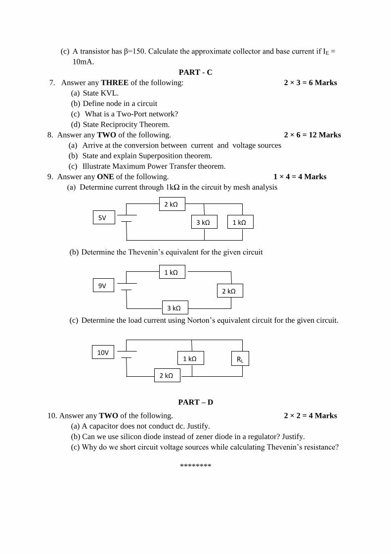
9. Answer any ONE of the following. 1 × 4 = 4 Marks
(a) Determine current through 1kΩ in the circuit by mesh analysis
(b) Determine the Thevenin’s equivalent for the given circuit
(c) Determine the load current using Norton’s equivalent circuit for the given circuit.
PART – D
10. Answer any TWO of the following. 2 × 2 = 4 Marks
(a) A capacitor does not conduct dc. Justify.
(b) Can we use silicon diode instead of zener diode in a regulator? Justify.
(c) Why do we short circuit voltage sources while calculating Thevenin’s resistance?
********
2 kΩ
3 kΩ 1 kΩ 5V
1 kΩ
3 kΩ
2 kΩ 9V
1 kΩ
2 kΩ
RL
10V


![Semester 1 Review Paper 2 2018 [106 marks] - Uplift Education...Semester 1 Review Paper 2 2018 [106 marks] 1a. A group of 800 students answered 40 questions on a category of their](https://img.pdfslide.us/doc/110x75/5ebd19ff7126c35afb789641/semester-1-review-paper-2-2018-106-marks-uplift-education-semester-1-review.jpg)


![Unisa Study Notes - QUESTION TOPIC MARKS · 2 FAC1501 May/June 2017 [TURN OVER] QUESTION 1 (20 marks)(24 minutes) This question must be answered on a mark reading sheet. Select for](https://img.pdfslide.us/doc/110x75/5f53500265425475ec5f2915/unisa-study-notes-question-topic-marks-2-fac1501-mayjune-2017-turn-over-question.jpg)