Embed Size (px)
Citation preview
Journal of Engineering Volume 18 May 2012 Number 5
639
Numerical Simulation of flow in pipe with cross jet effects
Karema Assi Hamad
Assistant Lecturer
Department of Electromechanical Engineering
University of Technology – Baghdad
Abstract
A numerical method is developed to obtain two-dimensional velocity and pressure distribution through a cylindrical pipe with cross jet flows. The method is based on solving partial differential equations for the conservation of mass and momentum by finite difference method to convert them into algebraic equations. This well-known problem is used to introduce the basic concepts of CFD including: the finite- difference mesh, the discrete nature of the numerical solution, and the dependence of the result on the mesh refinement. Staggered grid implementation of the numerical model is used. The set of algebraic equations is solved simultaneously by “SIMPLE” algorithm to obtain velocity and pressure distribution within a pipe. In order to verify the validity for present code, the flow behavior predicted by this code is compared with these of another studies and there is a good agreement is obtained. Keywords : numerical, CFD, laminar flow, cross flow, flow in pipe.
التمثيل العددي للجريان في انبوب بيتأثير نفث جانبي خالل الجريان المتقاطع الخالصة
وب اسطواني المقطع الثنائي ة لمعرفة التوزيع تم تطوير طريقة حل عددي األبعاد للسرعة والضغط خالل انباطع ان متق ع جري زخم . م ة وال ظ الكتل ة لحف لية الجزئي ادالت التفاض ل المع ى ح ة عل دت الطريق د اعتم وق
(conservation of both mass and momentum) ـددة ات المحـ رو ق ة الف بواسطة استخدام طريق(finite difference method)دًا لتطبيق . لتحويلها إلى معادالت جبرية ذا التطبيق المعروف جي يستخدم ه
سابي ع الح ك الموائ تخدام دينامي ل باس اهيم الح ددة (CFD)مف ات المح د الفروق ع عق ة توزي ضمنة آيفي والمتى ا ائج عل ة النت ذلك اعتمادي ة وآ ك الطريق ة بتل د ضمن وطبيعة واسلوب طريقة الحل العددي ع العق سلوب توزي
د ين العق ة ب ددي (Staggered grid) استخدم .الحيز من حيث تقليل المسافات البيني م .في نموذج الحل الع تسرعة (SIMPLE” algorithm“)حل مجموعة المعادالت الجبرية في وقت واحد بطريقة ع ال لمعرفة توزي
ة مع ولغرض التحقق من وثوقية الطريق . والضغط خالل االنبوب ة الحالي ائج العددي ة النت ة الحالية تمت مقارن . وقد بينت المقارنة توافقية جيدة،نتائج الحل التحليلي للجريان احادي االبعاد خالل االنابيب
Numerical Simulation of flow in pipe with cross jet effects
Karema Assi Hamad
640
Introduction The analysis of pipe flow is very important in engineering point of view. A lot of engineering problem dealt with it. Due to rigorous engineering application and implications the analysis is important. The flow of real fluid exhibits viscous effects in pipe flow. Here this effect is identified for laminar flow condition. The application of momentum equation is used to evaluate the velocity and pressure distribution in a pipe under laminar flow condition. (Baniasad et al.,2009 ). Presented numerical prediction of two- dimensional laminar heat transfer to water flow at critical pressure. The set of governing equations containing continuity, momentum and energy are solved simultaneously using CFD technique. The discretized form of each equation is obtained by finite volume method and the SIMPLE algorithm is used for pressure-velocity calculations. (Mahmud et al.,2009). Presented numerical study to predict hydrodynamic and thermal characteristics in a pipe with sinusoidal wavy surface for steady laminar flow . The integral forms of governing equations are discretized using control volume based Finite Volume method with collocated variable arrangement. SIMPLE algorithm is used and TDMA solver is applied for solution of system of equations. (Shimomukai and Kanda 2008). Studies the computation of pipe flow in the entrance region. The pressure distribution and flow characteristics, particularly the effect of vorticity in the vicinity of the wall, are analyzed for Reynolds numbers ranging from 500 to 10000. (Smith et al., 2008). Described the flow through circular orifice by using computational fluid dynamics (CFD) with various turbulence modeling. Effects of orifice diameter ratios (d/D = 0.5, 0.6, and 0.8) on flow field characteristics is extensively investigated. To study the influence of turbulence model on the predicted results, the standard k-ε turbulence model was employed to compare with the Reynolds Stress Model.
(Voronova and Nikitin 2006). Present complete Navier-Stokes equations for the turbulent flow in a pipe of elliptical cross-section with semiaxis ratio b/a = 0.5 is directly calculated for the Reynolds number Re = 6000 (determined from the mean-flow velocity and the hydraulic diameter). The distribution of the average and pulsatory flow characteristics over the pipe cross-section are obtained. In particular, the secondary flow in the cross-section plane, typical of turbulent flows in noncircular pipes, is calculated. (Voronova and Nikitin 2006). Studied the turbulent flow in a pipe with an elliptical cross section is directly simulated at Re = 4000 (where Re is calculated in terms of the mean velocity and the hydraulic diameter). The incompressible Navier-Stokes equations are solved in curvilinear orthogonal coordinates by using a central-difference approximation in space and a third-order accurate semi-implicit Runge-Kutta method for time integration. The distributions of the mean and fluctuation characteristics of the turbulent motion over the pipe’s cross section are computed. (Akinlade 2005). reports the effects of surface roughness on the flow characteristics in a turbulent boundary layer. Both experimental and numerical investigations are used. A new wall function formulation based on a power law was proposed for smooth and fully rough wall turbulent pipe flow. The new formulation correctly predicted the friction factors for smooth and fully rough wall turbulent pipe flow. (Gerald 2002). Presents a CFD mode based on Matlab implementation to predict fully-developed laminar flow in a pipe (Surjosatyo and Ani 2001). Present a simulation study of a cold-flow in coaxial pipes with varying drive pipe diameter and entrance displacement. To predict these flow characteristics, a numerical method was employed by the differencing scheme for integrating the continuity equation and energy equation. A k-ε turbulent model was used to simulate the turbulent transport quantities. The 2-D flow pattern was created as the result of using fluent version 4.4 CFD modeling package
Journal of Engineering Volume 18 May 2012 Number 5
641
(Yakhot et al.,1999). Studied A pulsating laminar flow of a viscous, incompressible liquid in a rectangular duct. The motion is induced under an imposed pulsating pressure difference. The problem is solved numerically. Different flow regimes are characterized by a non-dimensional parameter based on the frequency (v) of the imposed pressure gradient oscillations and the width of the duct (h). In the present study a two-dimensional numerical method is presented to obtain velocity and pressure distribution through a cylindrical pipe. The method is based on solving partial differential equations for the conservation of mass and momentum by finite difference method. Numerical solution The governing equations
The equations for conservation of mass and momentum for incompressible, steady and laminar flow in cylindrical coordinate system of the r and z directions are given below (Graebel, 2007) (i) Mass Conservation .
( ) ( ) 01 =∂∂+
∂∂ uzrvrr
ρρ (1)
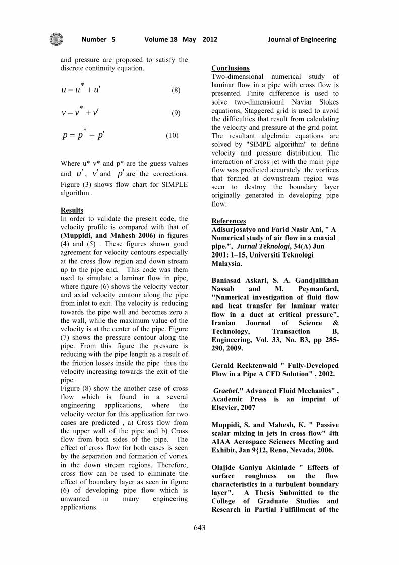
(ii) Momentum Conservation . ( r ) – direction
⎟⎠⎞
⎜⎝⎛ −∇+
∂∂
−
=⎟⎠⎞
⎜⎝⎛
∂∂
+∂∂
22
rvv
rP
zvu
rvv
µ
ρ (2)
(z) – direction
uzP
zuu
ruv
2∇+∂∂
−
=⎟⎠⎞
⎜⎝⎛
∂∂
+∂∂
µ
ρ (3)
Finite Difference Formulation of the
Equations The basic of the numerical method
is the conversion of the differential equations (1, 2 and 3) into algebraic equations relating the value of the dependent variables at the considered grid
point to the its values at the neighboring grid points. This was done by finite difference method.
After treating the governing equations by (FDM), the general form of the resultant equation can be termed as ( Patankar 1980) :
B
SNWEPPA A +=
⎟⎟⎟
⎠
⎞
⎜⎜⎜
⎝
⎛∑ ΦΦ
,,,
(4)
Where Φ is the general form of the dependent variable (Adisurjosatyo 2001).
This equation is known as a two-dimensional discretization equation. Where ( AE, AW, AN, and AS, ) are the neighboring coefficient representing the convection and diffusion terms of the mass entering the cell at its boundary surfaces, which are equal to :
21
21
zeu
zEA∆
−∆
= µρ (5a)
21
21
zwu
zWA∆
−∆
−= µρ (5b)
221
rjrnrnv
rNA∆
−∆
= µρ (5c)
221
rjrsrsv
rSA∆
−∆
−= µρ (5d)
1,,,
B
SNWEPA A +=
⎟⎟⎟
⎠
⎞
⎜⎜⎜
⎝
⎛∑ (5e)
Where the subscript ( P ) denotes
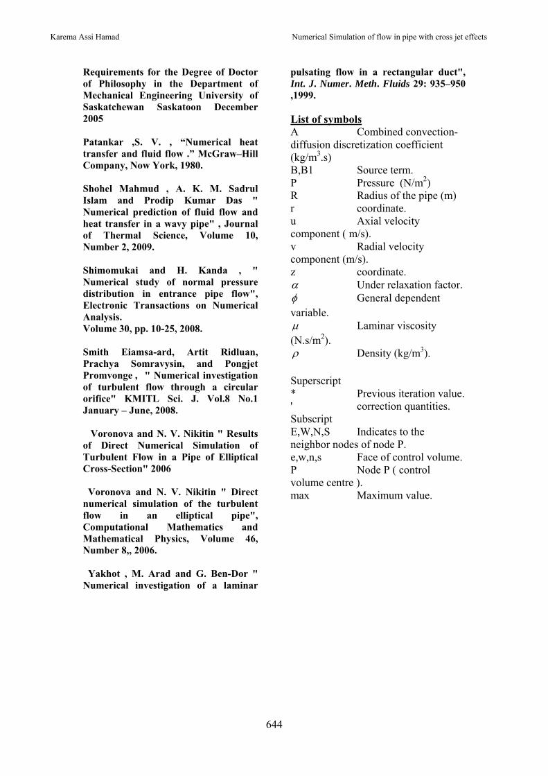
the corresponding grid point. The small letters subscript (e, w, n and s ) denote the value of the variable at the faces of the control volume. Fig (1) shows the
Numerical Simulation of flow in pipe with cross jet effects
Karema Assi Hamad
642
corresponding grid point and its neighbor grid points, and the u velocity component.
Table (1) illustrates the value of (B) for Equation (4) and the value of (B1) for Equation (5e) for the governing equations.
Method of Solution
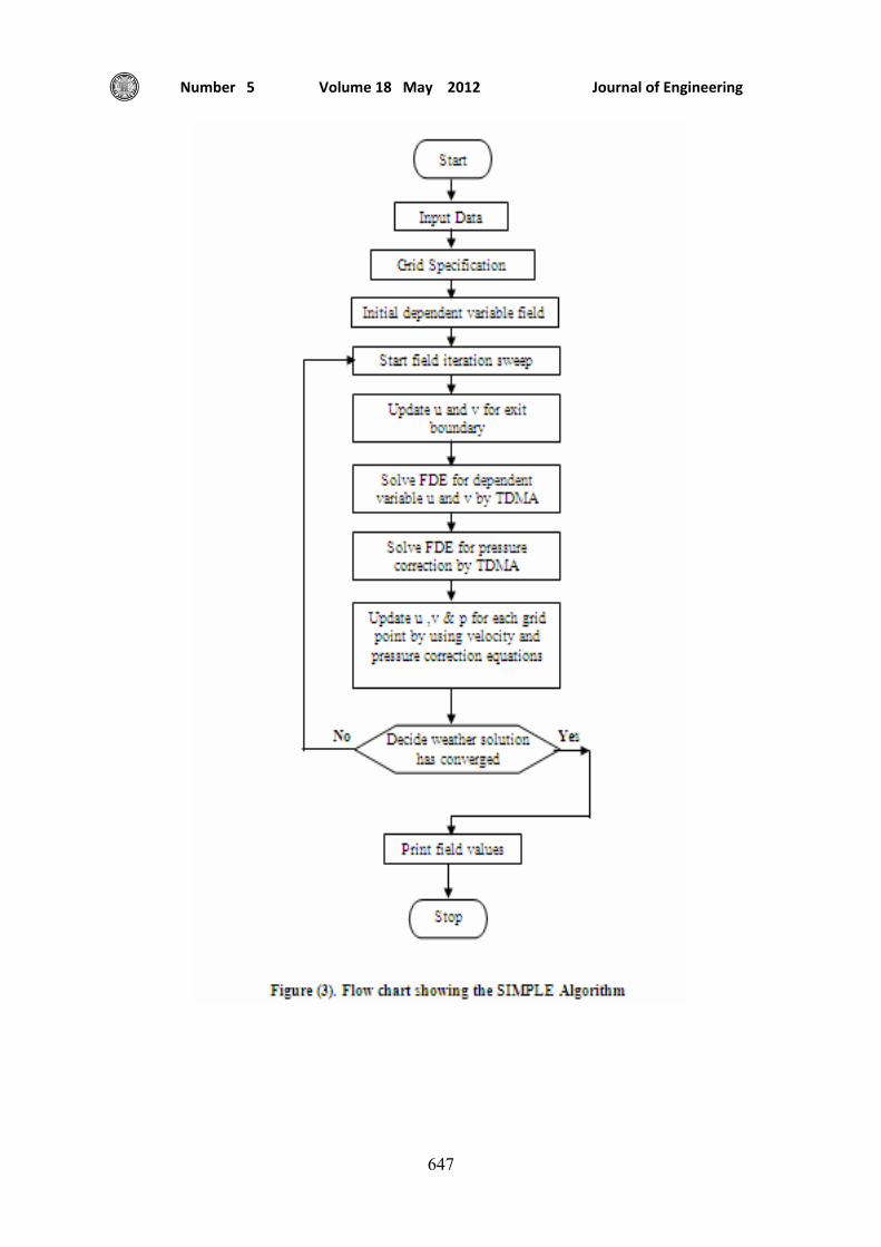
The first step in the solution is dividing the flow field into grid points, then the partial differential equations would be transformed into an algebraic form by finite-difference method as illustrated in the previous section. The discretized procedure of the equation is based on the power law scheme ( Patankar 1980) and the discretized equations are solved by (TDMA) ( Try Diagonal Matrix Algorithm) with under-relaxation factor 0.75 for pressure and 0.45 for velocity. The pressure and velocity are linked by the SIMPLE algorithm ( Patankar 1980).
Computer Program Descriptions
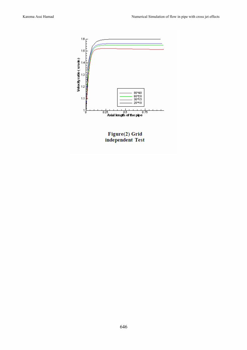
A computer program in FORTRAN-90 is written to solve a set of the partial differential equations that govern the flow field. The field is divided into grid points, which are distributed in r and z coordinates. There are four sets of grid without clustering are tested, where (30*15) is chosen because this set ensure good results in addition is a time saving as shown in Figure (2) .
Boundary conditions
1. Steady state. 2. The velocity components at the
wall are set equal to zero, because of the viscous nature of the flow.
3. At inlet the (u) velocity component is defined while the (v) component is set equal to zero.
4. At exit, the velocity are floating (smooth exit)
Staggered grid
Co-located storage of the pressure and velocity variables at the cell centers leads to the problem of checker boarding. This is because the cell centre values of pressure and velocity get cancelled out on expanding the face gradient terms. To overcome this problem staggered grid has
been used for discretization of the momentum equations. The staggered grid for the u momentum equation is shown in Figure (1) along with the neighboring velocity vectors for calculation of velocity gradients. Staggered grid in vertical direction is used for v momentum equation. Pressure is stored on the original grid and the pressure difference terms are evaluated as a difference of cell centre pressure values. Under-relaxation The velocity corrections are approximated by dropping the velocity part of the corrected momentum equations which places the entire burden of the velocity correction on pressure correction. Large pressure corrections might lead to poor pressure iterates so the pressure correction is under-relaxed to correct p*.It is necessary to under-relax the momentum equations due to the nonlinear nature of the equations.
ppp p ′+= α* (6)
( ) Pnbnb
PP
ABA /)1(
∑ +Φ
+Φ−=Φ
α
α (7)
SIMPLE Solver Algorithm
Semi-Implicit Method for Pressure-Linked Equations was first proposed by Patankar and Spalding (1972). Here we start with the discrete continuity equation and substitute into this the discrete u and v momentum equations containing the pressure terms resulting in a equation for discrete pressures. SIMPLE actually solves for a relative quantity called pressure correction. We guess an initial flow field and pressure distribution in the domain. The set of momentum and continuity equations are coupled and are nonlinear so we solve the equations iteratively. The pressure field is assumed to be known from the previous iteration. Using this u and v momentum equations to solve for the velocities. At this stage the newly obtained velocities don't satisfy continuity since the pressure field assumed is only a guess. Corrections to velocities
Journal of Engineering Volume 18 May 2012 Number 5
643
and pressure are proposed to satisfy the discrete continuity equation.
uuu ′+= * (8)
vvv ′+= * (9)
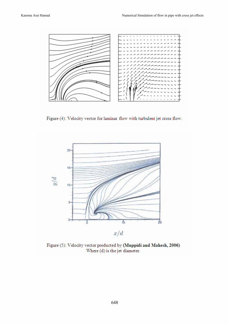
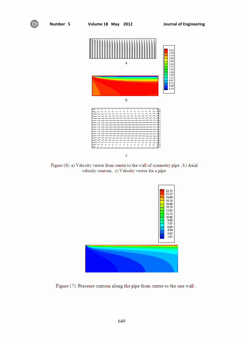
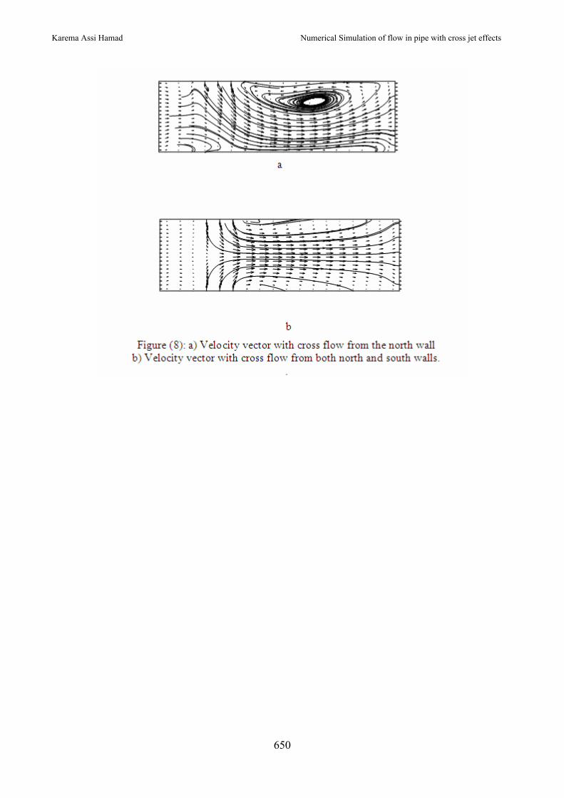
ppp ′+= * (10) Where u* v* and p* are the guess values and u′ , v′and p′ are the corrections. Figure (3) shows flow chart for SIMPLE algorithm . Results In order to validate the present code, the velocity profile is compared with that of (Muppidi, and Mahesh 2006) in figures (4) and (5) . These figures shown good agreement for velocity contours especially at the cross flow region and down stream up to the pipe end. This code was them used to simulate a laminar flow in pipe, where figure (6) shows the velocity vector and axial velocity contour along the pipe from inlet to exit. The velocity is reducing towards the pipe wall and becomes zero a the wall, while the maximum value of the velocity is at the center of the pipe. Figure (7) shows the pressure contour along the pipe. From this figure the pressure is reducing with the pipe length as a result of the friction losses inside the pipe thus the velocity increasing towards the exit of the pipe . Figure (8) show the another case of cross flow which is found in a several engineering applications, where the velocity vector for this application for two cases are predicted , a) Cross flow from the upper wall of the pipe and b) Cross flow from both sides of the pipe. The effect of cross flow for both cases is seen by the separation and formation of vortex in the down stream regions. Therefore, cross flow can be used to eliminate the effect of boundary layer as seen in figure (6) of developing pipe flow which is unwanted in many engineering applications.
Conclusions Two-dimensional numerical study of laminar flow in a pipe with cross flow is presented. Finite difference is used to solve two-dimensional Naviar Stokes equations; Staggered grid is used to avoid the difficulties that result from calculating the velocity and pressure at the grid point. The resultant algebraic equations are solved by "SIMPE algorithm" to define velocity and pressure distribution. The interaction of cross jet with the main pipe flow was predicted accurately .the vortices that formed at downstream region was seen to destroy the boundary layer originally generated in developing pipe flow. References Adisurjosatyo and Farid Nasir Ani, " A Numerical study of air flow in a coaxial pipe.", Jurnal Teknologi, 34(A) Jun 2001: 1–15, Universiti Teknologi Malaysia.
Baniasad Askari, S. A. Gandjalikhan Nassab and M. Peymanfard, "Nnmerical investigation of fluid flow and heat transfer for laminar water flow in a duct at critical pressure", Iranian Journal of Science & Technology, Transaction B, Engineering, Vol. 33, No. B3, pp 285-290, 2009. Gerald Recktenwald " Fully-Developed Flow in a Pipe A CFD Solution" , 2002. Graebel," Advanced Fluid Mechanics" , Academic Press is an imprint of Elsevier, 2007 Muppidi, S. and Mahesh, K. " Passive scalar mixing in jets in cross flow" 4th AIAA Aerospace Sciences Meeting and Exhibit, Jan 9{12, Reno, Nevada, 2006. Olajide Ganiyu Akinlade " Effects of surface roughness on the flow characteristics in a turbulent boundary layer", A Thesis Submitted to the College of Graduate Studies and Research in Partial Fulfillment of the
Numerical Simulation of flow in pipe with cross jet effects
Karema Assi Hamad
644
Requirements for the Degree of Doctor of Philosophy in the Department of Mechanical Engineering University of Saskatchewan Saskatoon December 2005 Patankar ,S. V. , “Numerical heat transfer and fluid flow .” McGraw–Hill Company, Now York, 1980. Shohel Mahmud , A. K. M. Sadrul Islam and Prodip Kumar Das " Numerical prediction of fluid flow and heat transfer in a wavy pipe" , Journal of Thermal Science, Volume 10, Number 2, 2009. Shimomukai and H. Kanda , " Numerical study of normal pressure distribution in entrance pipe flow", Electronic Transactions on Numerical Analysis. Volume 30, pp. 10-25, 2008. Smith Eiamsa-ard, Artit Ridluan, Prachya Somravysin, and Pongjet Promvonge
, " Numerical investigation
of turbulent flow through a circular orifice" KMITL Sci. J. Vol.8 No.1 January – June, 2008. Voronova and N. V. Nikitin " Results of Direct Numerical Simulation of Turbulent Flow in a Pipe of Elliptical Cross-Section" 2006 Voronova and N. V. Nikitin " Direct numerical simulation of the turbulent flow in an elliptical pipe", Computational Mathematics and Mathematical Physics, Volume 46, Number 8,, 2006. Yakhot , M. Arad and G. Ben-Dor " Numerical investigation of a laminar
pulsating flow in a rectangular duct", Int. J. Numer. Meth. Fluids 29: 935–950 ,1999. List of symbols A Combined convection-diffusion discretization coefficient (kg/m3.s) B,B1 Source term. P Pressure (N/m2) R Radius of the pipe (m) r coordinate. u Axial velocity component ( m/s). v Radial velocity component (m/s). z coordinate. α Under relaxation factor. φ General dependent variable. µ Laminar viscosity (N.s/m2). ρ Density (kg/m3). Superscript * Previous iteration value. ' correction quantities. Subscript E,W,N,S Indicates to the neighbor nodes of node P. e,w,n,s Face of control volume. P Node P ( control volume centre ). max Maximum value.
Journal of Engineering Volume 18 May 2012 Number 5
645
Numerical Simulation of flow in pipe with cross jet effects
Karema Assi Hamad
646
Journal of Engineering Volume 18 May 2012 Number 5
647
Numerical Simulation of flow in pipe with cross jet effects
Karema Assi Hamad
648
Journal of Engineering Volume 18 May 2012 Number 5
649
Numerical Simulation of flow in pipe with cross jet effects
Karema Assi Hamad
650