Embed Size (px)
Citation preview
QMP 7.1 D/F
Channabasaveshwara Institute of Technology (NACC Accredited & An ISO 9001:2015 Certified Institution)
NH 206 (B.H. Road), Gubbi, Tumkur – 572 216. Karnataka.
Department of Electrical & Electronics Engineering
ELECTRICAL MACHINES
LABORATORY – 1
Lab Manual
18EEL37
B.E - III Semester
Lab Manual 2019-20
Name :__________________________________________________
USN :___________________________________________________
Batch : ___________________Section : ________________
QMP 7.1 D/F
Channabasaveshwara Institute of Technology (NACC Accredited & An ISO 9001:2015 Certified Institution)
NH 206 (B.H. Road), Gubbi, Tumkur – 572 216. Karnataka.
Department of Electrical & Electronics Engineering
ELECTRICAL MACHINES
LABORATORY – 1
Lab Manual
Version 3.0
August 2019
Prepared by: Reviewed by:
. Ramesh Bantwal V C Kumar
Assistant Professor Associate Professor V C Kumar
Associate Professor
Approved by:
V C Kumar Associate Professor & Head Dept. of EEE

Channabasaveshwara Institute of Technology (NACC Accredited & An ISO 9001:2015 Certified Institution)
NH 206 (B.H. Road), Gubbi, Tumkur – 572 216. Karnataka.
OUR VISION
To create centers of excellence in education and to serve the society by enhancing the
quality of life through value based professional leadership.
OUR MISSION
• To provide high quality technical and professionally relevant education in a diverse
learning environment.
• To provide the values that prepare students to lead their lives with personal integrity,
professional ethics and civic responsibility in a global society.
• To prepare the next generation of skilled professionals to successfully compete in the
diverse global market.
• To promote a campus environment that welcomes and honors women and men of all
races, creeds and cultures, values and intellectual curiosity, pursuit of knowledge and
academic integrity and freedom.
• To offer a wide variety of off-campus education and training programmes to individuals
and groups.
• To stimulate collaborative efforts with industry, universities, government and
professional societies.
• To facilitate public understanding of technical issues and achieve excellence in the
operations of the institute.
QUALITY POLICY
Our organization delights customers (students, parents and society) by providing value
added quality education to meet the national and international requirements. We also
provide necessary steps to train the students for placement and continue to improve
our methods of education to the students through effective quality management
system, quality policy and quality objectives.

Channabasaveshwara Institute of Technology (NACC Accredited & An ISO 9001:2015 Certified Institution)
NH 206 (B.H. Road), Gubbi, Tumkur – 572 216. Karnataka.
DEPARTMENT OF ELECTRICAL AND ELECTRONICS
ENGINEERING
VISION:
To be a department of excellence in electrical and electronics Engineering education and
Research, thereby to provide technically competent and ethical professionals to serve
the society.
MISSION:
• To provide high quality technical and professionally relevant education in the field of
electrical engineering.
• To prepare the next generation of electrically skilled professionals to successfully
compete in the diverse global market.
• To nurture their creative ideas through research activities.
• To promote research and development in electrical technology and management for
the benefit of the society.
To provide right ambience and opportunities for the students to develop into creative,
talented and globally competent professionals in electrical sector.

‘Instructions to the Candidates’
1. Students should come with thorough preparation for the experiment to be
conducted.
2. Students will not be permitted to attend the laboratory unless they bring the
practical record fully completed in all respects pertaining to the experiment
conducted in the previous class.
3. Experiment should be started only after the staff-in-charge has checked
the circuit diagram.
4. All the calculations should be made in the observation book. Specimen
calculations for one set of readings have to be shown in the practical
record.
5. Wherever graphs are to be drawn, A-4 size graphs only should be used
and the same should be firmly attached to the practical record.
6. Practical record should be neatly maintained.
7. The students should obtain the signature of the staff-in-charge in the
observation/manual book after completing each experiment.
8. Theory regarding each experiment should be written in the practical record
before procedure in your own words.
Instructions to the students’
1. Come prepared to the lab with relevant theory about the experiment you
are conducting.
2. Before switching on the power supply, make sure that the voltage knobs
are in minimum position and current knobs are in maximum position.
3. While using electrolytic capacitors, connect them in the right polarity.
4. Before doing the circuit connection, check the active components, CRO
probes, equipment etc., for their good working condition.
5. Do not use the multimeter, if the low battery indication comes
6. While using function generators make sure that DC offset is off
1. Don’t play with electricity.
2. Carelessness not only destroys the valuable equipment in the
lab but also costs your life.
3. Mere conduction of the experiment without a clear
knowledge of the theory is of no value.
4. Before you close the switch, think consequences.
5. Don’t close the switch until the faculty-in0charge checks the
circuit.
Course objectives & outcomes
Course objectives:
1. Conducting of different tests on transformers and
synchronous machine and evaluation of their performance.
2. Verify the parallel operation of two single phase
transformers of different KVA rating.
3. Study the connection of single phase transformers for three
phase operation and phase conversion.
4. Study of synchronous generator connected to infinite bus.
Course outcomes:
At the end of the course the student will be able to:
1. Conduct different tests on transformers and synchronous
generators and evaluate their performance.
2. Connect and operate two single phase transformers of
different KVA rating in parallel.
3. Connect single phase transformers for three phase operation
and phase conversion.
4. Assess the performance of synchronous generator connected
to infinite bus.
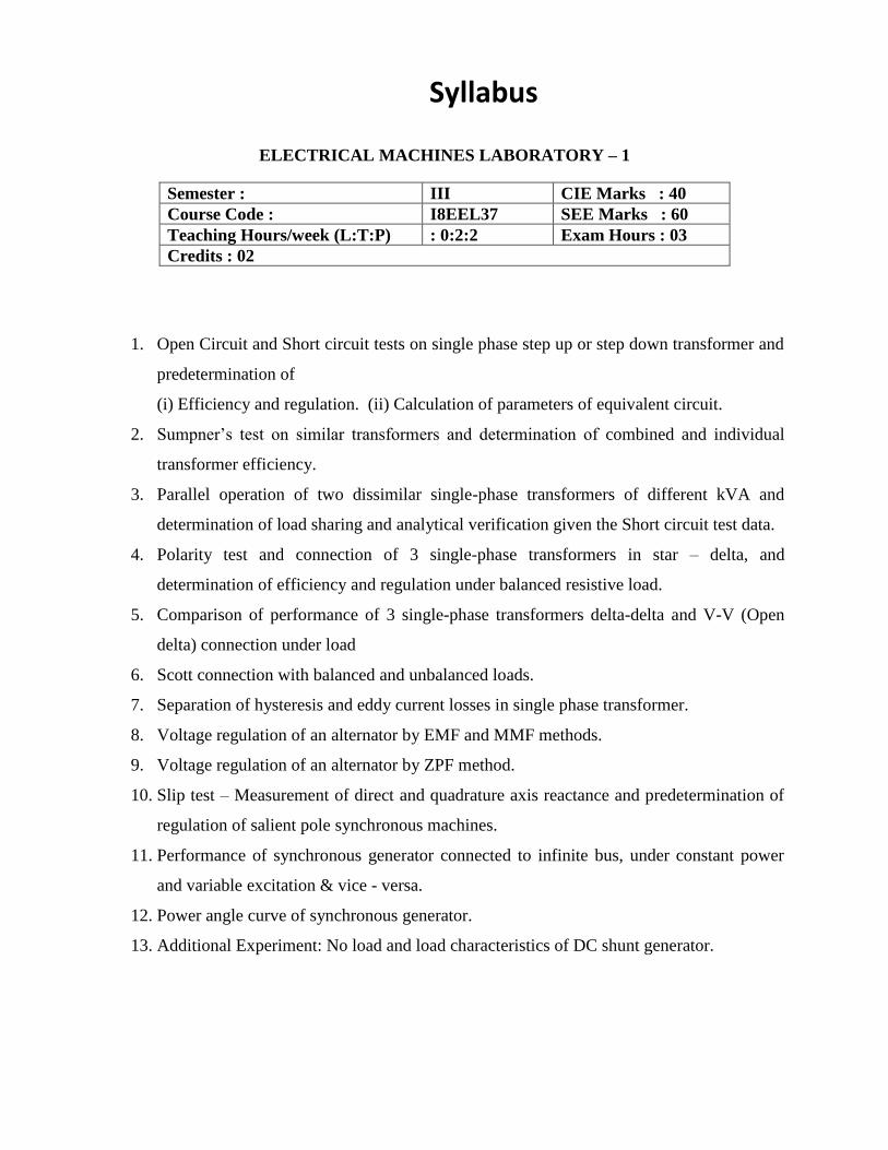
Syllabus
ELECTRICAL MACHINES LABORATORY – 1
Semester : III CIE Marks : 40
Course Code : I8EEL37 SEE Marks : 60
Teaching Hours/week (L:T:P) : 0:2:2 Exam Hours : 03
Credits : 02
1. Open Circuit and Short circuit tests on single phase step up or step down transformer and
predetermination of
(i) Efficiency and regulation. (ii) Calculation of parameters of equivalent circuit.
2. Sumpner’s test on similar transformers and determination of combined and individual
transformer efficiency.
3. Parallel operation of two dissimilar single-phase transformers of different kVA and
determination of load sharing and analytical verification given the Short circuit test data.
4. Polarity test and connection of 3 single-phase transformers in star – delta, and
determination of efficiency and regulation under balanced resistive load.
5. Comparison of performance of 3 single-phase transformers delta-delta and V-V (Open
delta) connection under load
6. Scott connection with balanced and unbalanced loads.
7. Separation of hysteresis and eddy current losses in single phase transformer.
8. Voltage regulation of an alternator by EMF and MMF methods.
9. Voltage regulation of an alternator by ZPF method.
10. Slip test – Measurement of direct and quadrature axis reactance and predetermination of
regulation of salient pole synchronous machines.
11. Performance of synchronous generator connected to infinite bus, under constant power
and variable excitation & vice - versa.
12. Power angle curve of synchronous generator.
13. Additional Experiment: No load and load characteristics of DC shunt generator.

INDEX PAGE
Note:
• If the student fails to attend the regular lab, the experiment has to
be completed in the same week. Then the manual/observation and
record will be evaluated for 50% of maximum marks.
Sl.
No. Name of the Experiment
Date
Ob
servati
on
Mark
s
(Ma
x .
20)
Rec
ord
M
ark
s
(Ma
x.
5)
Sig
na
ture
(Stu
den
t)
Sig
na
ture
(Fa
cult
y)
Conduction Repetition Submission
of Record
Average
Channabasaveshwara Institute of Technology (NACC Accredited & An ISO 9001:2015 Certified Institution)
NH 206 (B.H. Road), Gubbi, Tumkur – 572 216. Karnataka.
DEPARTMENT OF ELECTRICAL AND ELECTRONICS ENGINEERING
CONTENTS
First Cycle Experiments
Expt. No. Title of the Experiment Page No.
1 Regulation of Alternator by EMF and MMF Method. 02
2 OC & SC Tests on 1-Ф Transformer. 10
3 Slip Test on Alternator. 16
4 Scott Connection. 20
5 Separation of hysteresis and eddy current losses in single phase transformer. 22
6 Polarity test on 1-ф transformer and connection of 3 single-phase transformers in star – delta
26
Second Cycle Experiments
Expt. No. Title of the Experiment Page No.
7 Polarity Test and connection of 3 single-phase transformers in delta – delta and V – V (open-delta) connection under load.
30
8 Sumpner’s Test. 36
9 Performance of synchronous generator connected to infinite bus, under constant power and variable excitation & vice - versa.
40
10 Regulation of Alternator by ZPF Method. 46
11 Parallel Operation of Two 1-Ф Transformers. 52
12 Power angle curve of synchronous generator. 56
Additional Experiments:
Additional Experiment: No load and load characteristics of DC shunt generator 62
Question bank 67
Viva - voce Questions 69
References 71
Appendix (Symbols) 72
18EEL37 : Electrical Machines Laboratory-I 2019-20
Dept. of EEE, CIT-Gubbi, 572 216 Page No.1
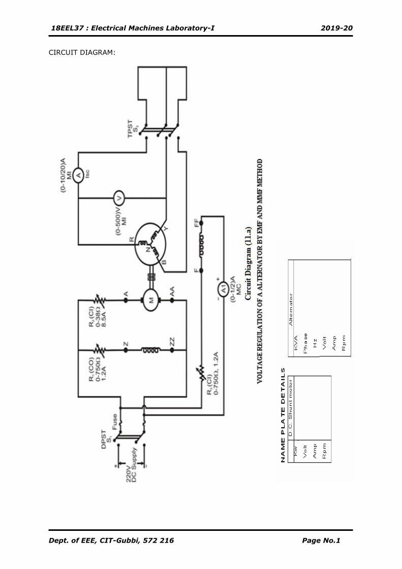
CIRCUIT DIAGRAM:
18EEL37 : Electrical Machines Laboratory-I 2019-20
Dept. of EEE, CIT-Gubbi, 572 216 Page No.2
Experiment No. 1 Date: __/__/_____
REGULATION OF ALTERNATOR BY EMF AND MMF METHOD
Aim
To determine the percentage regulation of the given three phase alternator by
Open circuit and short circuit tests.
• By EMF method
• By MMF method
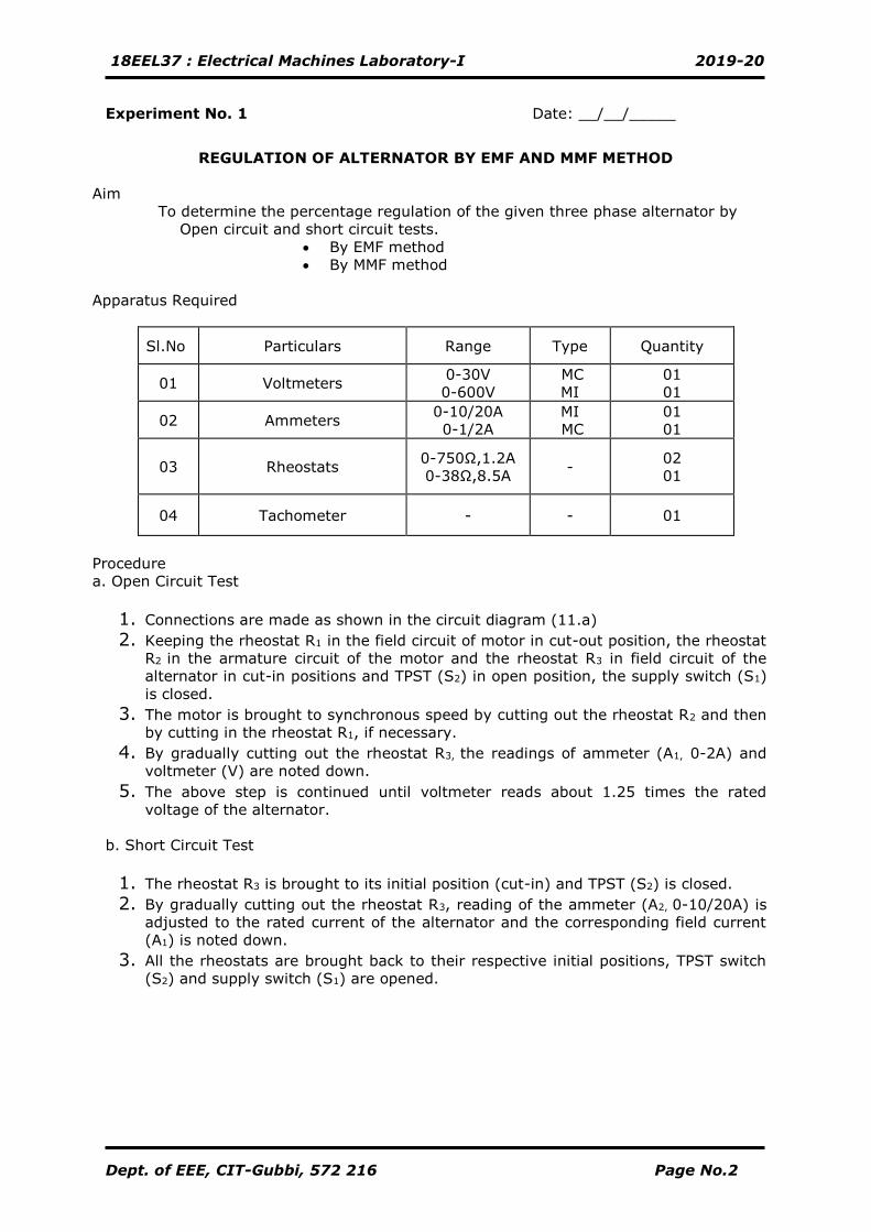
Apparatus Required
Sl.No Particulars Range Type Quantity
01 Voltmeters 0-30V
0-600V
MC
MI
01
01
02 Ammeters 0-10/20A
0-1/2A
MI
MC
01
01
03 Rheostats 0-750Ω,1.2A
0-38Ω,8.5A -
02
01
04 Tachometer - - 01
Procedure
a. Open Circuit Test
1. Connections are made as shown in the circuit diagram (11.a)
2. Keeping the rheostat R1 in the field circuit of motor in cut-out position, the rheostat
R2 in the armature circuit of the motor and the rheostat R3 in field circuit of the
alternator in cut-in positions and TPST (S2) in open position, the supply switch (S1)
is closed.
3. The motor is brought to synchronous speed by cutting out the rheostat R2 and then
by cutting in the rheostat R1, if necessary.
4. By gradually cutting out the rheostat R3, the readings of ammeter (A1, 0-2A) and
voltmeter (V) are noted down.
5. The above step is continued until voltmeter reads about 1.25 times the rated
voltage of the alternator.
b. Short Circuit Test
1. The rheostat R3 is brought to its initial position (cut-in) and TPST (S2) is closed.
2. By gradually cutting out the rheostat R3, reading of the ammeter (A2, 0-10/20A) is
adjusted to the rated current of the alternator and the corresponding field current
(A1) is noted down.
3. All the rheostats are brought back to their respective initial positions, TPST switch
(S2) and supply switch (S1) are opened.
18EEL37 : Electrical Machines Laboratory-I 2019-20
Dept. of EEE, CIT-Gubbi, 572 216 Page No.3
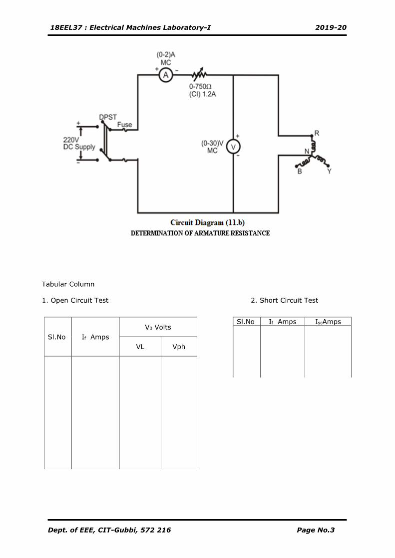
Tabular Column
1. Open Circuit Test 2. Short Circuit Test
Sl.No If Amps
V0 Volts
VL Vph
Sl.No If Amps IscAmps
18EEL37 : Electrical Machines Laboratory-I 2019-20
Dept. of EEE, CIT-Gubbi, 572 216 Page No.4
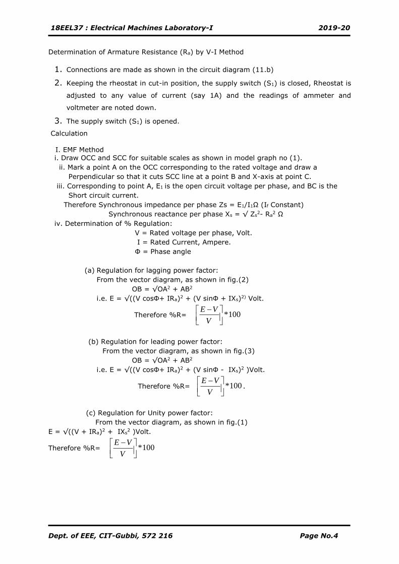
Determination of Armature Resistance (Ra) by V-I Method
1. Connections are made as shown in the circuit diagram (11.b)
2. Keeping the rheostat in cut-in position, the supply switch (S1) is closed, Rheostat is
adjusted to any value of current (say 1A) and the readings of ammeter and
voltmeter are noted down.
3. The supply switch (S1) is opened.
Calculation
I. EMF Method
i. Draw OCC and SCC for suitable scales as shown in model graph no (1).
ii. Mark a point A on the OCC corresponding to the rated voltage and draw a
Perpendicular so that it cuts SCC line at a point B and X-axis at point C.
iii. Corresponding to point A, E1 is the open circuit voltage per phase, and BC is the
Short circuit current.
Therefore Synchronous impedance per phase Zs = E1/I1Ω (If Constant)
Synchronous reactance per phase Xs = √ Zs2- Ra
2 Ω
iv. Determination of % Regulation:
V = Rated voltage per phase, Volt.
I = Rated Current, Ampere.
Ф = Phase angle
(a) Regulation for lagging power factor:
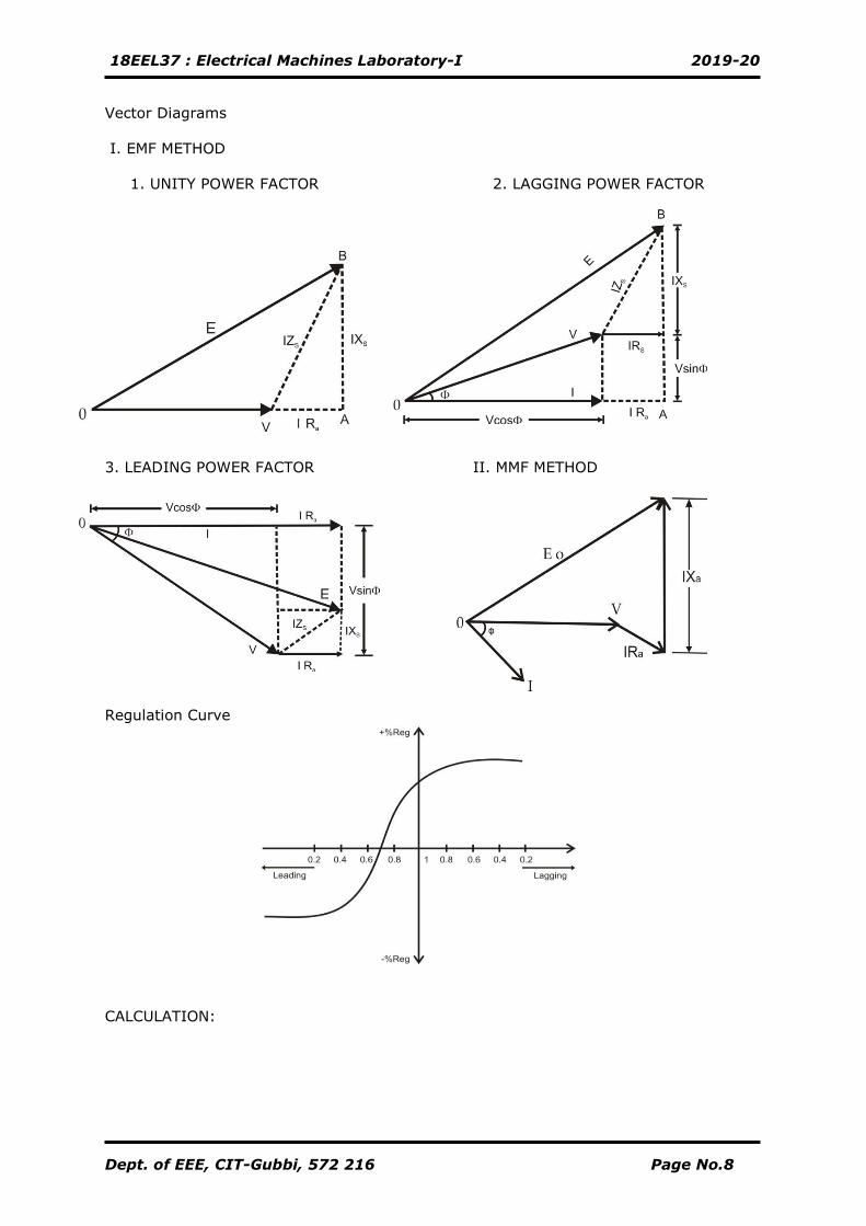
From the vector diagram, as shown in fig.(2)
OB = √OA2 + AB2
i.e. E = √((V cosФ+ IRa)2 + (V sinФ + IXs)2) Volt.
Therefore %R= 100*
−
V
VE
(b) Regulation for leading power factor:
From the vector diagram, as shown in fig.(3)
OB = √OA2 + AB2
i.e. E = √((V cosФ+ IRa)2 + (V sinФ - IXs)2 )Volt.
Therefore %R= 100*
−
V
VE.
(c) Regulation for Unity power factor:
From the vector diagram, as shown in fig.(1)
E = √((V + IRa)2 + IXs2 )Volt.
Therefore %R= 100*
−
V
VE
18EEL37 : Electrical Machines Laboratory-I 2019-20
Dept. of EEE, CIT-Gubbi, 572 216 Page No.5
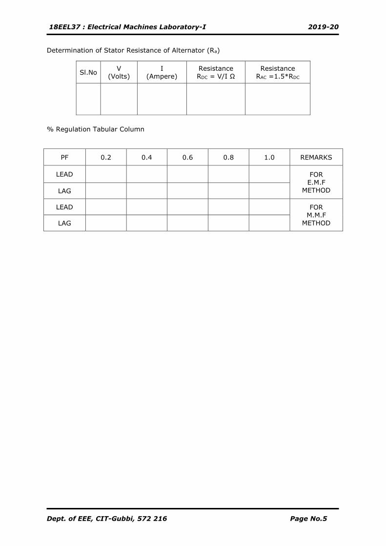
Determination of Stator Resistance of Alternator (Ra)
% Regulation Tabular Column
PF 0.2 0.4 0.6 0.8 1.0 REMARKS
LEAD
FOR
E.M.F
METHOD LAG
LEAD
FOR
M.M.F
METHOD LAG
Sl.No V
(Volts)
I
(Ampere)
Resistance
RDC = V/I Ω
Resistance
RAC =1.5*RDC
18EEL37 : Electrical Machines Laboratory-I 2019-20
Dept. of EEE, CIT-Gubbi, 572 216 Page No.6
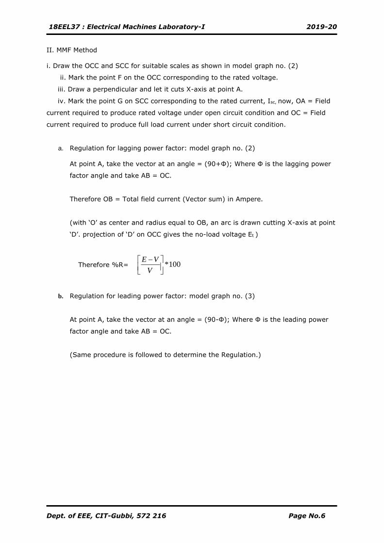
II. MMF Method
i. Draw the OCC and SCC for suitable scales as shown in model graph no. (2)
ii. Mark the point F on the OCC corresponding to the rated voltage.
iii. Draw a perpendicular and let it cuts X-axis at point A.
iv. Mark the point G on SCC corresponding to the rated current, Isc, now, OA = Field
current required to produce rated voltage under open circuit condition and OC = Field
current required to produce full load current under short circuit condition.
a. Regulation for lagging power factor: model graph no. (2)
At point A, take the vector at an angle = (90+Ф); Where Ф is the lagging power
factor angle and take AB = OC.
Therefore OB = Total field current (Vector sum) in Ampere.
(with ‘O’ as center and radius equal to OB, an arc is drawn cutting X-axis at point
‘D’. projection of ‘D’ on OCC gives the no-load voltage Et )
Therefore %R= 100*
−
V
VE
b. Regulation for leading power factor: model graph no. (3)
At point A, take the vector at an angle = (90-Ф); Where Ф is the leading power
factor angle and take AB = OC.
(Same procedure is followed to determine the Regulation.)
18EEL37 : Electrical Machines Laboratory-I 2019-20
Dept. of EEE, CIT-Gubbi, 572 216 Page No.7
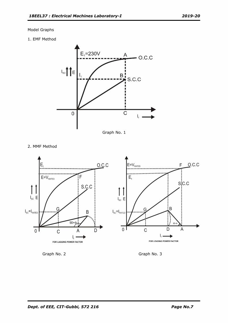
Model Graphs
1. EMF Method
Graph No. 1
2. MMF Method
Graph No. 2 Graph No. 3
18EEL37 : Electrical Machines Laboratory-I 2019-20
Dept. of EEE, CIT-Gubbi, 572 216 Page No.8
Vector Diagrams
I. EMF METHOD
1. UNITY POWER FACTOR 2. LAGGING POWER FACTOR
3. LEADING POWER FACTOR II. MMF METHOD
Regulation Curve
CALCULATION:
18EEL37 : Electrical Machines Laboratory-I 2019-20
Dept. of EEE, CIT-Gubbi, 572 216 Page No.9
CIRCUIT DIAGRAM:
18EEL37 : Electrical Machines Laboratory-I 2019-20
Dept. of EEE, CIT-Gubbi, 572 216 Page No.10
Experiment No.02 Date: __/__/_____
OPEN CIRCUIT (OC)& SHORT CIRCUIT (SC) TEST ON 1-Ф TRANSFORMER
AIM:
By conducting Open circuit and Short Circuit tests on a given 1-Ф transformer to
predetermine efficiency, voltage regulation and to draw its equivalent circuit.
APPARATUS REQUIRED:
Sl. No Particulars. Range Type Quantity
01. Voltmeter 0-300V
0-30V
MI
MI
01
01
02 Ammeter. 0-2A
0-10/20A
MI
MI
01
01
03. Wattmeter. 2A,300V LPF 01
10/20A,75V UPF 01
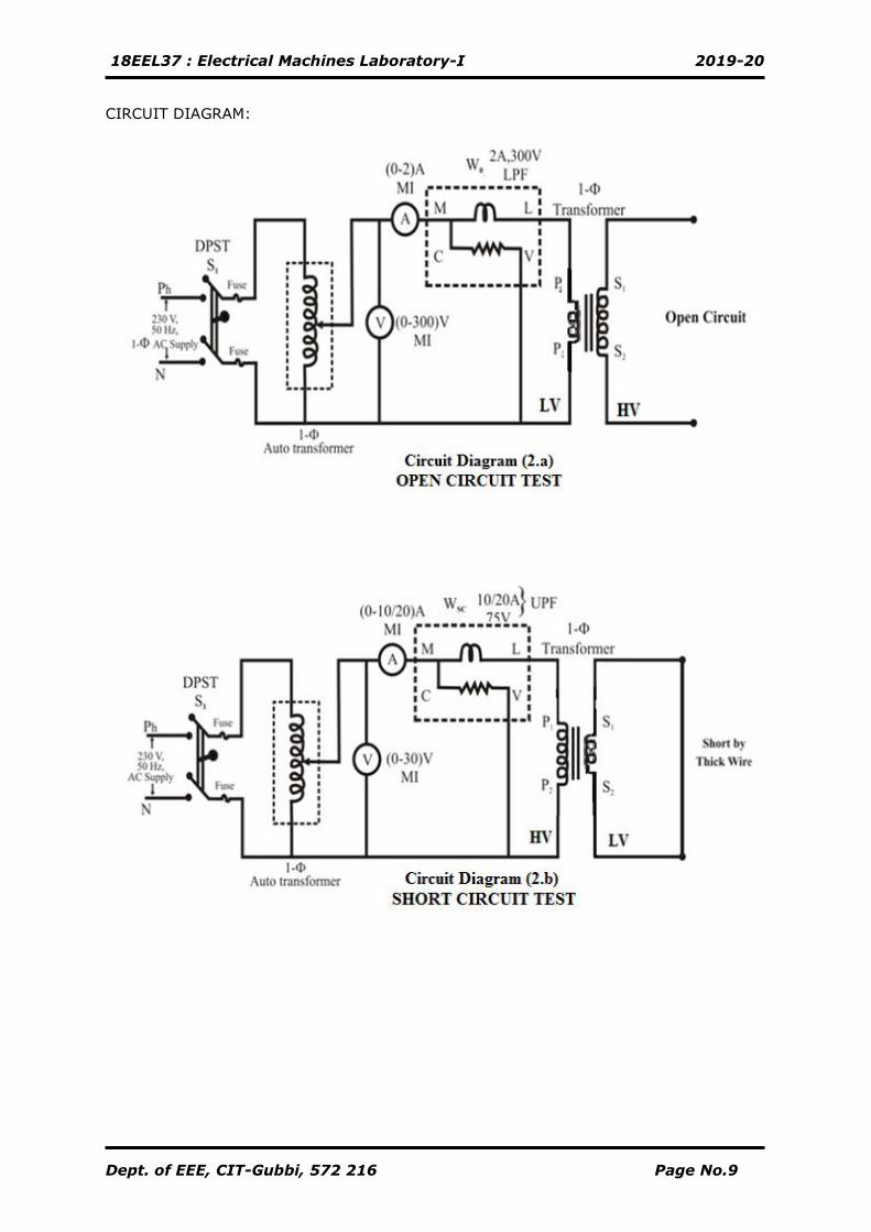
PROCEDURE:
1. OPEN CIRCUIT TEST
1. Connections are made as shown in the circuit diagram (2.a).
2. By keeping auto-transformer voltage in zero out-put position, the supply switch
(S1) is closed.
3. Vary the auto transformer voltage gradually and apply rated voltage to the LV
side of the transformer and keep the HV side open.
4. The readings of all the meters are noted down.
5. The auto-transformer is brought back to its initial zero output position, the supply
switch (S1) is opened.
2. SHORT CIRCUIT TEST
1. Connections are made as shown in the circuit diagram (2.b).
2. Keeping auto-transformer voltage in zero out-put position, the supply switch (S1)
is closed.
3. By varying the 1-Ф auto transformer, a low voltage is applied to HV side of the
transformer such that the rated current flows through it and short the LV side of
the transformer.
4. The Primary rated current is given by :
I1 = (kVA * 1000) / Rated Primary voltage (V1).
5. The readings of all the meters are noted down.
6. The auto-transformer is brought back to its initial zero output position, the supply
switch (S1) is opened.
18EEL37 : Electrical Machines Laboratory-I 2019-20
Dept. of EEE, CIT-Gubbi, 572 216 Page No.11
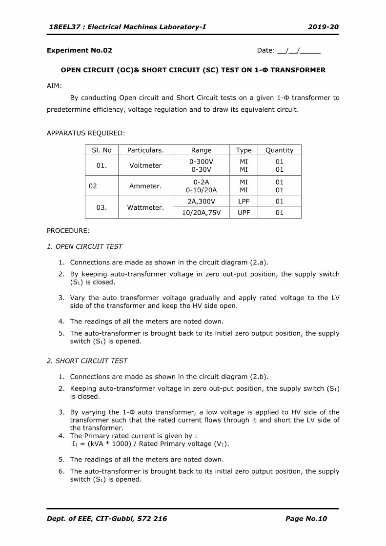
TABULAR COLUMN:
1. OPEN CIRCUIT TEST
Sl.No VO(Volts) IO(Amps) WO
(Watt)
2. SHORT CIRCUIT TEST
Sl.No VSC(Volts) ISC(Amps) Wsc
(Watt)
NOTE:1) Wo = (k1 × Watt Meter Reading.) Where, k1 = Deflection Scale Full
) CosI(V selsel
Wsc = (k2 × Watt Meter Reading.) Where, k2 = Deflection Scale Full
) CosI(V selsel
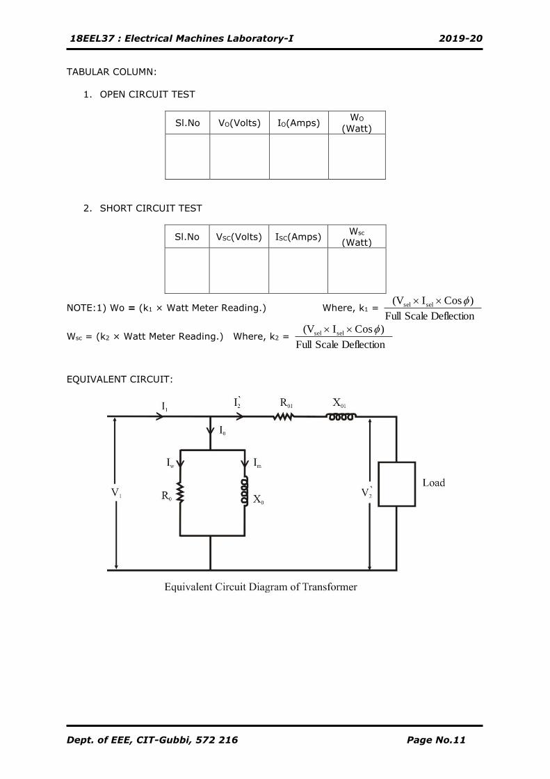
EQUIVALENT CIRCUIT:
18EEL37 : Electrical Machines Laboratory-I 2019-20
Dept. of EEE, CIT-Gubbi, 572 216 Page No.12
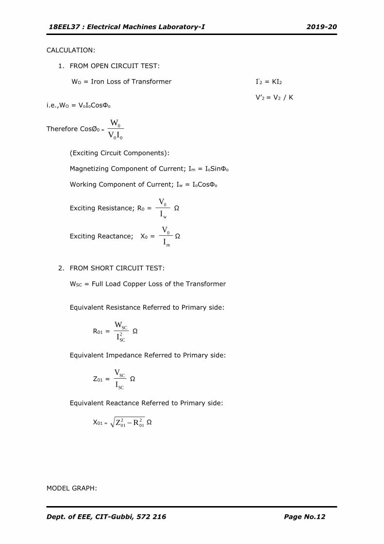
CALCULATION:
1. FROM OPEN CIRCUIT TEST:
WO = Iron Loss of Transformer I’2 = KI2
V’2 = V2 / K
i.e.,WO = VoIoCosФo
Therefore CosØ0 =
00
0
IV
W
(Exciting Circuit Components):
Magnetizing Component of Current; Im = IoSinФo
Working Component of Current; Iw = IoCosФo
Exciting Resistance; R0 = I
V
w
0 Ω
Exciting Reactance; X0 = I
V
m
0Ω
2. FROM SHORT CIRCUIT TEST:
WSC = Full Load Copper Loss of the Transformer
Equivalent Resistance Referred to Primary side:
R01 = 2
SC
SC
I
W Ω
Equivalent Impedance Referred to Primary side:
Z01 =
SC
SC
I
V Ω
Equivalent Reactance Referred to Primary side:
X01 = 2
01
2
01 RZ − Ω
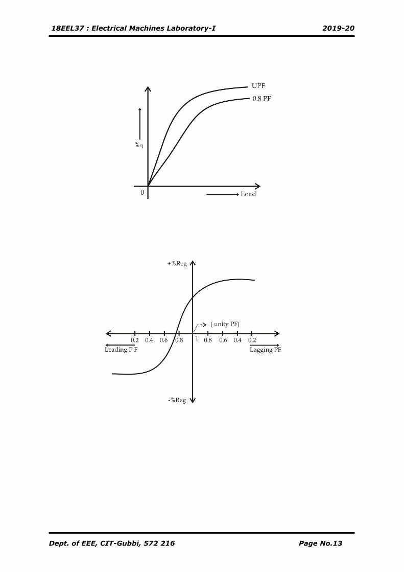
MODEL GRAPH:
18EEL37 : Electrical Machines Laboratory-I 2019-20
Dept. of EEE, CIT-Gubbi, 572 216 Page No.13
18EEL37 : Electrical Machines Laboratory-I 2019-20
Dept. of EEE, CIT-Gubbi, 572 216 Page No.14
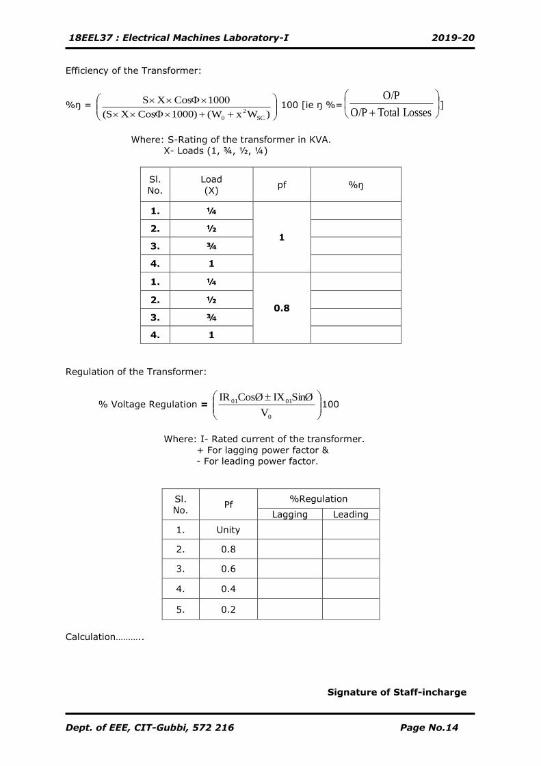
Efficiency of the Transformer:
%ŋ =
++
)WxW()1000Cos X(S
1000Cos XS
SC
2
0
100 [ie ŋ %=
+ Losses TotalO/P
O/P]
Where: S-Rating of the transformer in KVA.
X- Loads (1, ¾, ½, ¼)
Sl.
No.
Load
(X) pf %ŋ
1. ¼
1
2. ½
3. ¾
4. 1
1. ¼
0.8
2. ½
3. ¾
4. 1
Regulation of the Transformer:
% Voltage Regulation = 100
Where: I- Rated current of the transformer.
+ For lagging power factor &
- For leading power factor.
Sl.
No. Pf
%Regulation
Lagging Leading
1. Unity
2. 0.8
3. 0.6
4. 0.4
5. 0.2
Calculation………..
Signature of Staff-incharge
0
0101
V
SinØIXCosØIR
18EEL37 : Electrical Machines Laboratory-I 2019-20
Dept. of EEE, CIT-Gubbi, 572 216 Page No.15
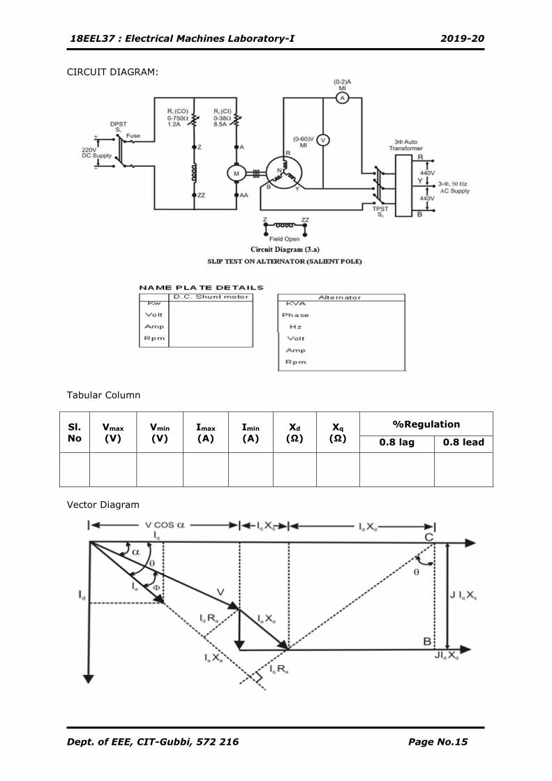
CIRCUIT DIAGRAM:
Tabular Column
Sl.
No
Vmax
(V)
Vmin
(V)
Imax
(A)
Imin
(A)
Xd
(Ω)
Xq
(Ω)
%Regulation
0.8 lag 0.8 lead
Vector Diagram
18EEL37 : Electrical Machines Laboratory-I 2019-20
Dept. of EEE, CIT-Gubbi, 572 216 Page No.16
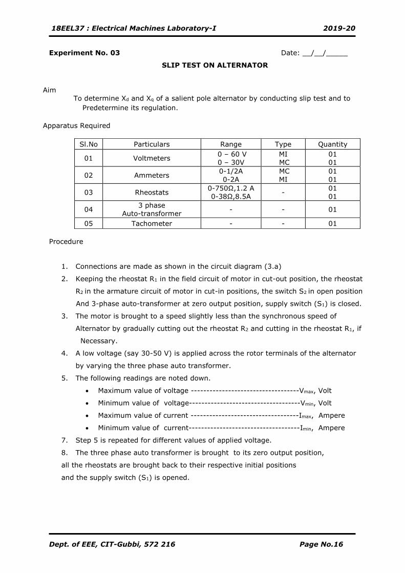
Experiment No. 03 Date: __/__/_____
SLIP TEST ON ALTERNATOR
Aim
To determine Xd and Xq of a salient pole alternator by conducting slip test and to
Predetermine its regulation.
Apparatus Required
Procedure
1. Connections are made as shown in the circuit diagram (3.a)
2. Keeping the rheostat R1 in the field circuit of motor in cut-out position, the rheostat
R2 in the armature circuit of motor in cut-in positions, the switch S2 in open position
And 3-phase auto-transformer at zero output position, supply switch (S1) is closed.
3. The motor is brought to a speed slightly less than the synchronous speed of
Alternator by gradually cutting out the rheostat R2 and cutting in the rheostat R1, if
Necessary.
4. A low voltage (say 30-50 V) is applied across the rotor terminals of the alternator
by varying the three phase auto transformer.
5. The following readings are noted down.
• Maximum value of voltage -----------------------------------Vmax, Volt
• Minimum value of voltage------------------------------------Vmin, Volt
• Maximum value of current -----------------------------------Imax, Ampere
• Minimum value of current------------------------------------Imin, Ampere
7. Step 5 is repeated for different values of applied voltage.
8. The three phase auto transformer is brought to its zero output position,
all the rheostats are brought back to their respective initial positions
and the supply switch (S1) is opened.
Sl.No Particulars Range Type Quantity
01 Voltmeters 0 – 60 V
0 – 30V
MI
MC
01
01
02 Ammeters 0-1/2A
0-2A
MC
MI
01
01
03 Rheostats 0-750Ω,1.2 A
0-38Ω,8.5A -
01
01
04 3 phase
Auto-transformer - - 01
05 Tachometer - - 01
18EEL37 : Electrical Machines Laboratory-I 2019-20
Dept. of EEE, CIT-Gubbi, 572 216 Page No.17
Determination of Stator Resistance of Alternator (Ra)
Sl.
No
V
(Volts)
I
(Ampere)
Resistance
RDC = V/I Ω
Resistance
RAC =1.5 × RDC
18EEL37 : Electrical Machines Laboratory-I 2019-20
Dept. of EEE, CIT-Gubbi, 572 216 Page No.18
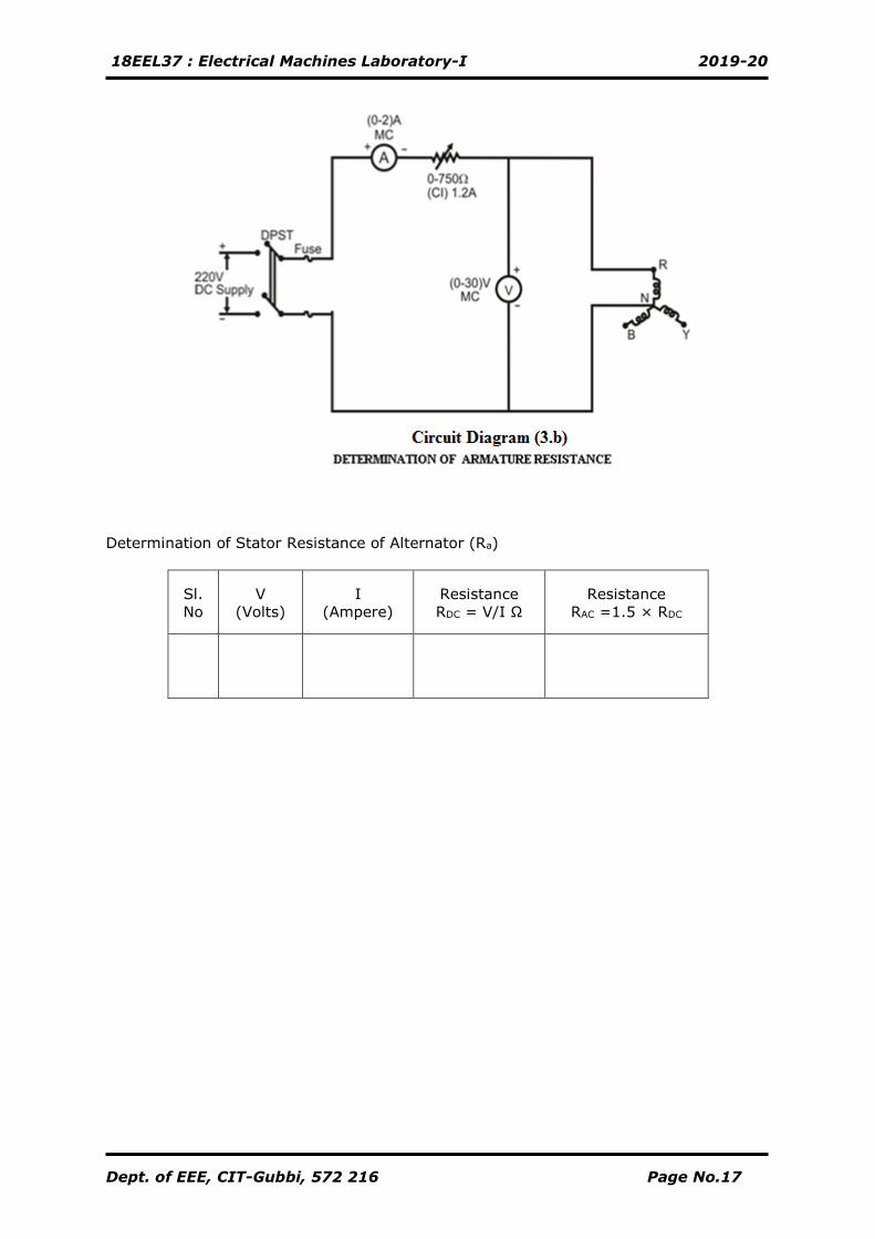
Determination of Stator Resistance (Ra)
a. Connections are made as shown in the circuit diagram (3.b).
b. By keeping rheostat in cut-in position the supply switch (S1) is closed.
Rheostat is adjusted to any value of current (say 1A)
c. All the meter readings are noted down.
d. The supply switch (S1) is opened.
NOTE: Field of the alternator is kept opened.
Calculation
V =Rated phaseVoltage, Volt
I = Rated current, Ampere.
Xd= Vmax / Imin =…………… Ω
Xq = Vmin / Imax =…………… Ω
For 0.8 p.f lagging
CosФ = 0.8
SinФ = 0.6
Therefore Ф = 36.86
tanθ = ( V Sin Ф ± I Xq ) / (V Cos Ф + I Ra) ( Note: + → lag , - → lead)
θ = tan-1 ((V Sin Ф ± I Xq ) / (V Cos Ф + I Ra))
Therefore α =θ - Ф
Therefore
Eo/phase = (V Cos α ± Id .Xd + Iq Ra) Volt
Where Iq= I Cos θ
Id = I Sin θ
Therefore
Regulation %R= 100*
−
V
VEo
Signature of Staff-incharge
18EEL37 : Electrical Machines Laboratory-I 2019-20
Dept. of EEE, CIT-Gubbi, 572 216 Page No.19
CIRCUIT DIAGRAM:
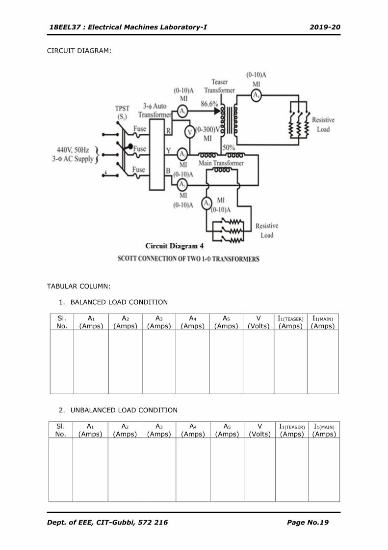
TABULAR COLUMN:
1. BALANCED LOAD CONDITION
Sl.
No.
A1
(Amps)
A2
(Amps)
A3
(Amps)
A4
(Amps)
A5
(Amps)
V
(Volts)
I1(TEASER)
(Amps)
I1(MAIN)
(Amps)
2. UNBALANCED LOAD CONDITION
Sl.
No.
A1
(Amps)
A2
(Amps)
A3
(Amps)
A4
(Amps)
A5
(Amps)
V
(Volts)
I1(TEASER)
(Amps)
I1(MAIN)
(Amps)
18EEL37 : Electrical Machines Laboratory-I 2019-20
Dept. of EEE, CIT-Gubbi, 572 216 Page No.20
Experiment No. 04 Date: __/__/_____
SCOTT CONNECTION
AIM:
To verify the currents in the main Transformer and teaser transformer in Scott
connection with balanced and unbalanced load.
APPARATUS REQUIRED:
Sl. No Particulars. Range Type Quantity
01. Voltmeter 0-600V MI 01
02. Ammeter 0-10A MI 05
PROCEDURE:
1. Connections are made as shown in the circuit diagram (4).
2. By keeping the 3-Ф auto transformer voltage in zero out-put and resistive loads
in off position, the supply switch (S1) is closed.
3. By varying the 3-Ф auto transformer, apply the rated voltage of the transformer
(1- Ф). [say 230V]
4. Close the load switch and apply load in steps till the rated current of the
transformer. At each step all the meter readings are noted down.
5. The resistive loads are brought back to the off position and 3-Ф auto-transformer
to its initial zero out-put position, the supply switch (S1) is opened.
Calculation:
I1T = 1.15 K I2T Amps where; K = transformation ration of transformer
I1M = K I2M Amps I2T = Secondary teaser transformer current
I2M = Secondary main transformer current
I1T = Primary teaser transformer current
I1M = Primary main transformer current.
Signature of Staff-incharge
18EEL37 : Electrical Machines Laboratory-I 2019-20
Dept. of EEE, CIT-Gubbi, 572 216 Page No.21
CIRCUIT DIAGRAM:
18EEL37 : Electrical Machines Laboratory-I 2019-20
Dept. of EEE, CIT-Gubbi, 572 216 Page No.22
Experiment No. 05 Date: __/__/_____
SEPARATION OF HYSTERESIS AND EDDY CURRENT LOSSES IN SINGLE PHASE
TRANSFORMER.
AIM:
To separation the Eddy current loss and Hysteresis loss from the iron loss of 1-Φ
transformer.
APPARATUS REQUIRED:
Sl. No Particulars. Range Type Quantity
01. Voltmeter 0-300V MI 01
02. Ammeter 0-10A MI 02
02. Ammeter 0-2A MC 02
03 Rheostats 0-400Ω,1.7A
0-150Ω,2A -
02
01
04 Tachometer - Digital 01
05. Wattmeter 10A,600V LPF 01
PROCEDURE:
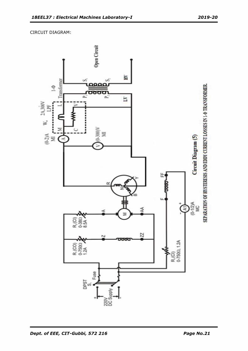
1. Connections are made as shown in the circuit diagram (5).
2. The prime mover is started with the help of 3-point starter and it is made to run
at rated speed.
3. By varying alternators field rheostat gradually, the rated primary voltage is
applied to transformer.
4. By adjusting the speed of prime mover the required frequency, is obtained and
corresponding reading are noted.
5. The experiment is repeated for different frequency and corresponding readings
are tabulated.
6. The prime mover is switched off using the DPIC switch after bringing all the
rheostats to initial position
7. From the tabulated readings the iron loss is separated from eddy current loss and
hysteresis loss by using respective formulae.
18EEL37 : Electrical Machines Laboratory-I 2019-20
Dept. of EEE, CIT-Gubbi, 572 216 Page No.23
TABULAR COLUMN
MODEL GRAPH
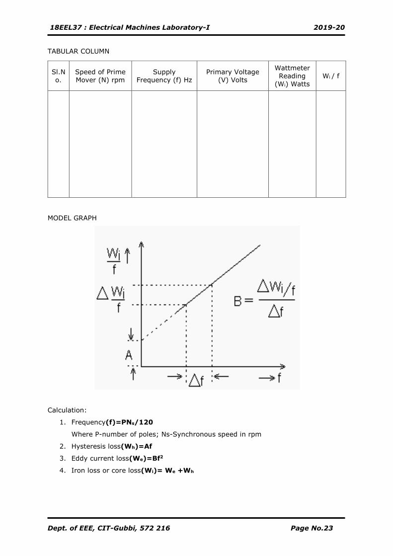
Calculation:
1. Frequency(f)=PNs/120
Where P-number of poles; Ns-Synchronous speed in rpm
2. Hysteresis loss(Wh)=Af
3. Eddy current loss(We)=Bf2
4. Iron loss or core loss(Wi)= We +Wh
Sl.N
o.
Speed of Prime
Mover (N) rpm
Supply
Frequency (f) Hz
Primary Voltage
(V) Volts
Wattmeter
Reading
(Wi) Watts
Wi / f
18EEL37 : Electrical Machines Laboratory-I 2019-20
Dept. of EEE, CIT-Gubbi, 572 216 Page No.24
Signature of Staff-incharge
18EEL37 : Electrical Machines Laboratory-I 2019-20
Dept. of EEE, CIT-Gubbi, 572 216 Page No.25
CIRCUIT DIAGRAM:
TABULAR COLUMN:
Sl.No V
(Volts)
V1
(Volts)
Sl.No V
(Volts)
V1
(Volts)
18EEL37 : Electrical Machines Laboratory-I 2019-20
Dept. of EEE, CIT-Gubbi, 572 216 Page No.26
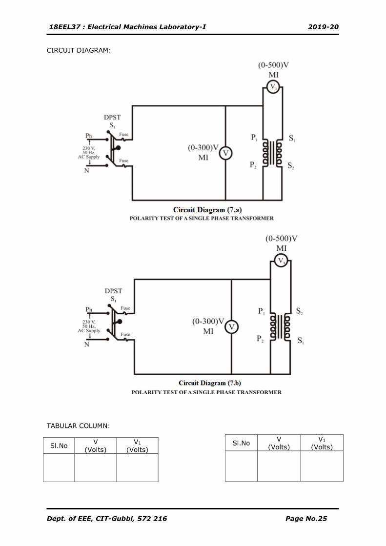
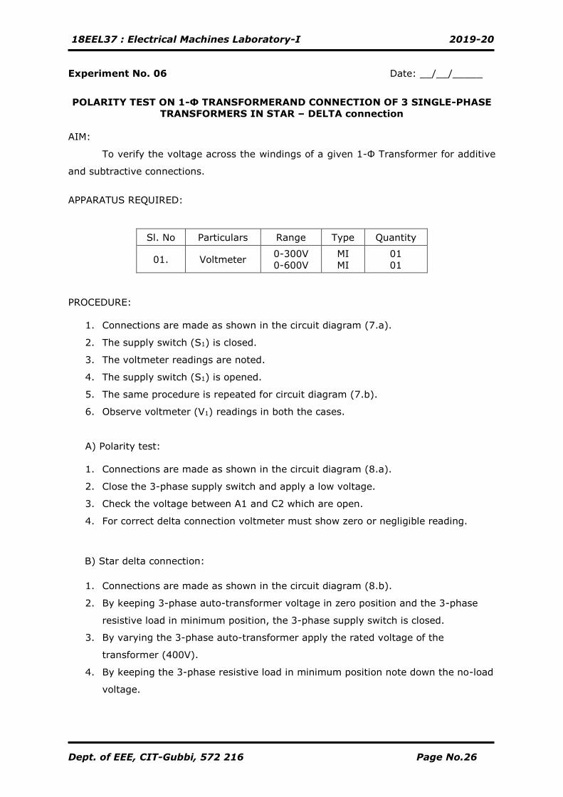
Experiment No. 06 Date: __/__/_____
POLARITY TEST ON 1-Ф TRANSFORMERAND CONNECTION OF 3 SINGLE-PHASE
TRANSFORMERS IN STAR – DELTA connection
AIM:
To verify the voltage across the windings of a given 1-Ф Transformer for additive
and subtractive connections.
APPARATUS REQUIRED:
Sl. No Particulars Range Type Quantity
01. Voltmeter 0-300V
0-600V
MI
MI
01
01
PROCEDURE:
1. Connections are made as shown in the circuit diagram (7.a).
2. The supply switch (S1) is closed.
3. The voltmeter readings are noted.
4. The supply switch (S1) is opened.
5. The same procedure is repeated for circuit diagram (7.b).
6. Observe voltmeter (V1) readings in both the cases.
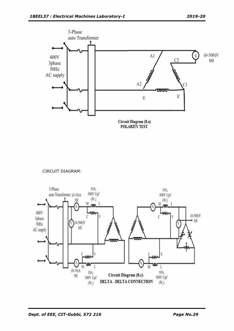
A) Polarity test:
1. Connections are made as shown in the circuit diagram (8.a).
2. Close the 3-phase supply switch and apply a low voltage.
3. Check the voltage between A1 and C2 which are open.
4. For correct delta connection voltmeter must show zero or negligible reading.
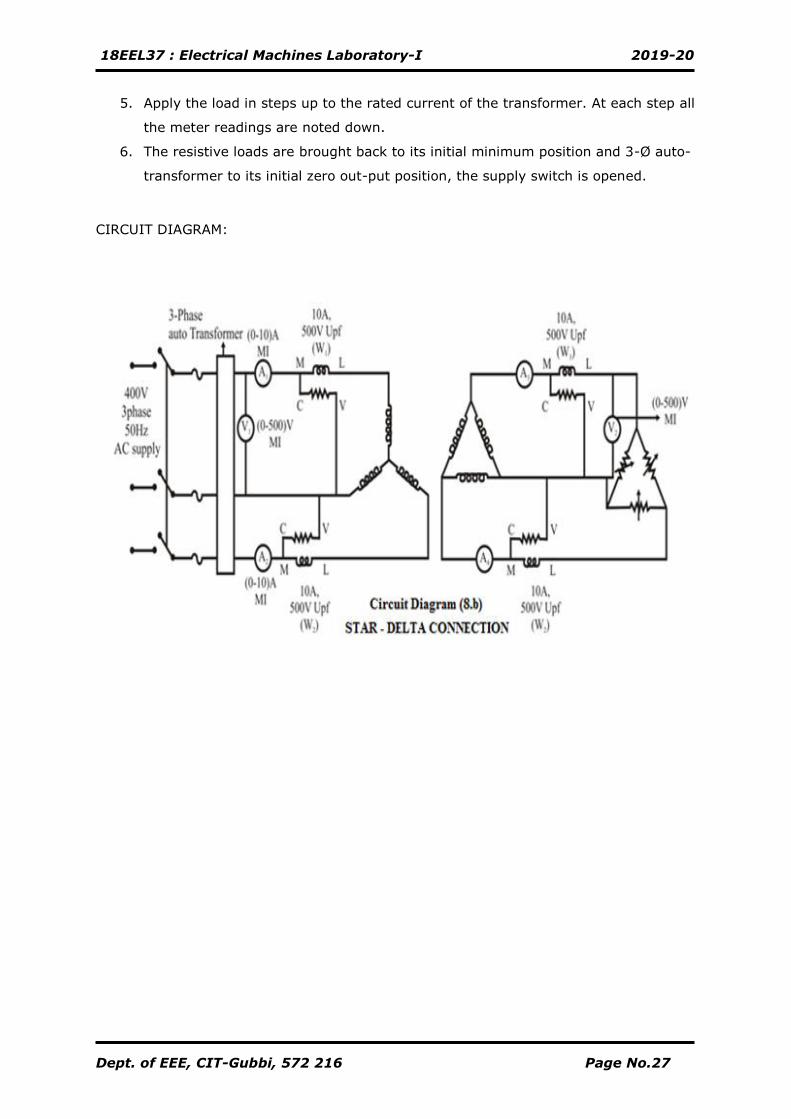
B) Star delta connection:
1. Connections are made as shown in the circuit diagram (8.b).
2. By keeping 3-phase auto-transformer voltage in zero position and the 3-phase
resistive load in minimum position, the 3-phase supply switch is closed.
3. By varying the 3-phase auto-transformer apply the rated voltage of the
transformer (400V).
4. By keeping the 3-phase resistive load in minimum position note down the no-load
voltage.
18EEL37 : Electrical Machines Laboratory-I 2019-20
Dept. of EEE, CIT-Gubbi, 572 216 Page No.27
5. Apply the load in steps up to the rated current of the transformer. At each step all
the meter readings are noted down.
6. The resistive loads are brought back to its initial minimum position and 3-Ø auto-
transformer to its initial zero out-put position, the supply switch is opened.
CIRCUIT DIAGRAM:
18EEL37 : Electrical Machines Laboratory-I 2019-20
Dept. of EEE, CIT-Gubbi, 572 216 Page No.28
18EEL37 : Electrical Machines Laboratory-I 2019-20
Dept. of EEE, CIT-Gubbi, 572 216 Page No.29
CIRCUIT DIAGRAM:
18EEL37 : Electrical Machines Laboratory-I 2019-20
Dept. of EEE, CIT-Gubbi, 572 216 Page No.30
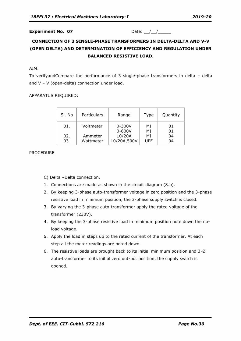
Experiment No. 07 Date: __/__/_____
CONNECTION OF 3 SINGLE-PHASE TRANSFORMERS IN DELTA-DELTA AND V-V
(OPEN DELTA) AND DETERMINATION OF EFFICIENCY AND REGULATION UNDER
BALANCED RESISTIVE LOAD.
AIM:
To verifyandCompare the performance of 3 single-phase transformers in delta – delta
and V – V (open-delta) connection under load.
APPARATUS REQUIRED:
Sl. No Particulars Range Type Quantity
01.
02.
03.
Voltmeter
Ammeter
Wattmeter
0-300V
0-600V
10/20A
10/20A,500V
MI
MI
MI
UPF
01
01
04
04
PROCEDURE
C) Delta –Delta connection.
1. Connections are made as shown in the circuit diagram (8.b).
2. By keeping 3-phase auto-transformer voltage in zero position and the 3-phase
resistive load in minimum position, the 3-phase supply switch is closed.
3. By varying the 3-phase auto-transformer apply the rated voltage of the
transformer (230V).
4. By keeping the 3-phase resistive load in minimum position note down the no-
load voltage.
5. Apply the load in steps up to the rated current of the transformer. At each
step all the meter readings are noted down.
6. The resistive loads are brought back to its initial minimum position and 3-Ø
auto-transformer to its initial zero out-put position, the supply switch is
opened.
18EEL37 : Electrical Machines Laboratory-I 2019-20
Dept. of EEE, CIT-Gubbi, 572 216 Page No.31
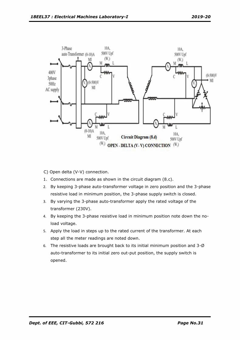
C) Open delta (V-V) connection.
1. Connections are made as shown in the circuit diagram (8.c).
2. By keeping 3-phase auto-transformer voltage in zero position and the 3-phase
resistive load in minimum position, the 3-phase supply switch is closed.
3. By varying the 3-phase auto-transformer apply the rated voltage of the
transformer (230V).
4. By keeping the 3-phase resistive load in minimum position note down the no-
load voltage.
5. Apply the load in steps up to the rated current of the transformer. At each
step all the meter readings are noted down.
6. The resistive loads are brought back to its initial minimum position and 3-Ø
auto-transformer to its initial zero out-put position, the supply switch is
opened.
18EEL37 : Electrical Machines Laboratory-I 2019-20
Dept. of EEE, CIT-Gubbi, 572 216 Page No.32
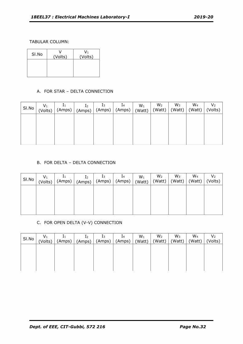
TABULAR COLUMN:
A. FOR STAR – DELTA CONNECTION
B. FOR DELTA – DELTA CONNECTION
C. FOR OPEN DELTA (V-V) CONNECTION
Sl.No V
(Volts)
V1
(Volts)
Sl.No V1
(Volts)
I1
(Amps) I2
(Amps)
I3
(Amps)
I4
(Amps) W1
(Watt)
W2
(Watt)
W3
(Watt)
W4
(Watt)
V2
(Volts)
Sl.No V1
(Volts)
I1
(Amps) I2
(Amps)
I3
(Amps)
I4
(Amps) W1
(Watt)
W2
(Watt)
W3
(Watt)
W4
(Watt)
V2
(Volts)
Sl.No V1
(Volts)
I1
(Amps) I2
(Amps)
I3
(Amps)
I4
(Amps) W1
(Watt)
W2
(Watt)
W3
(Watt)
W4
(Watt)
V2
(Volts)
18EEL37 : Electrical Machines Laboratory-I 2019-20
Dept. of EEE, CIT-Gubbi, 572 216 Page No.33
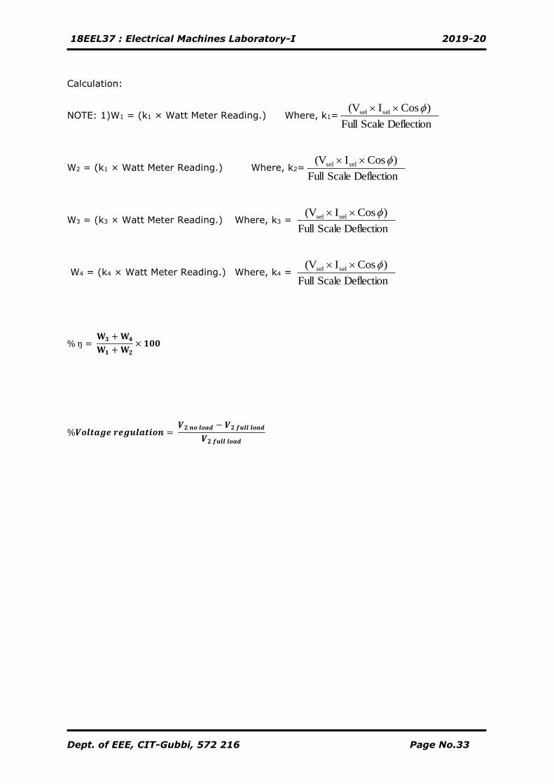
Calculation:
NOTE: 1)W1 = (k1 × Watt Meter Reading.) Where, k1= Deflection Scale Full
) CosI(V selsel
W2 = (k1 × Watt Meter Reading.) Where, k2= Deflection Scale Full
) CosI(V selsel
W3 = (k3 × Watt Meter Reading.) Where, k3 = Deflection Scale Full
) CosI(V selsel
W4 = (k4 × Watt Meter Reading.) Where, k4 = Deflection Scale Full
) CosI(V selsel
% ŋ = 𝐖𝟑 + 𝐖𝟒
𝐖𝟏 + 𝐖𝟐
× 𝟏𝟎𝟎
%𝑽𝒐𝒍𝒕𝒂𝒈𝒆 𝒓𝒆𝒈𝒖𝒍𝒂𝒕𝒊𝒐𝒏 = 𝑽𝟐 𝒏𝒐 𝒍𝒐𝒂𝒅 − 𝑽𝟐 𝒇𝒖𝒍𝒍 𝒍𝒐𝒂𝒅
𝑽𝟐 𝒇𝒖𝒍𝒍 𝒍𝒐𝒂𝒅
18EEL37 : Electrical Machines Laboratory-I 2019-20
Dept. of EEE, CIT-Gubbi, 572 216 Page No.34
18EEL37 : Electrical Machines Laboratory-I 2019-20
Dept. of EEE, CIT-Gubbi, 572 216 Page No.35
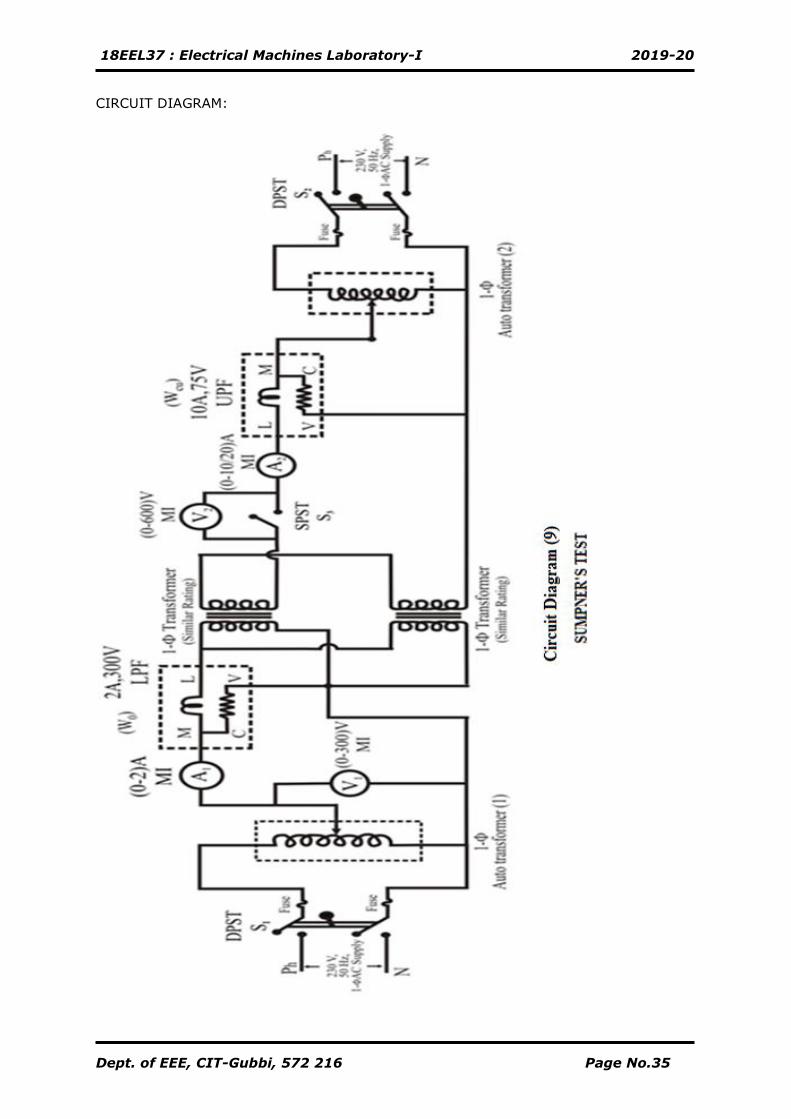
CIRCUIT DIAGRAM:
18EEL37 : Electrical Machines Laboratory-I 2019-20
Dept. of EEE, CIT-Gubbi, 572 216 Page No.36
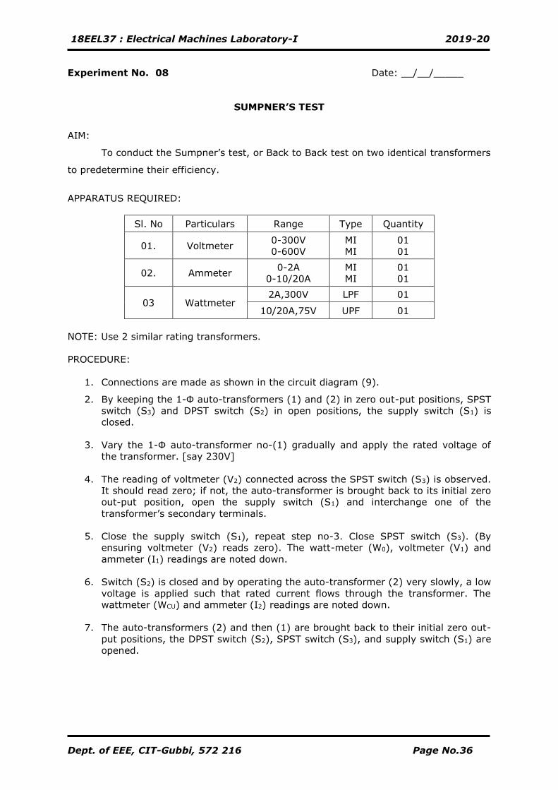
Experiment No. 08 Date: __/__/_____
SUMPNER’S TEST
AIM:
To conduct the Sumpner’s test, or Back to Back test on two identical transformers
to predetermine their efficiency.
APPARATUS REQUIRED:
Sl. No Particulars Range Type Quantity
01. Voltmeter 0-300V
0-600V
MI
MI
01
01
02. Ammeter 0-2A
0-10/20A
MI
MI
01
01
03 Wattmeter 2A,300V LPF 01
10/20A,75V UPF 01
NOTE: Use 2 similar rating transformers.
PROCEDURE:
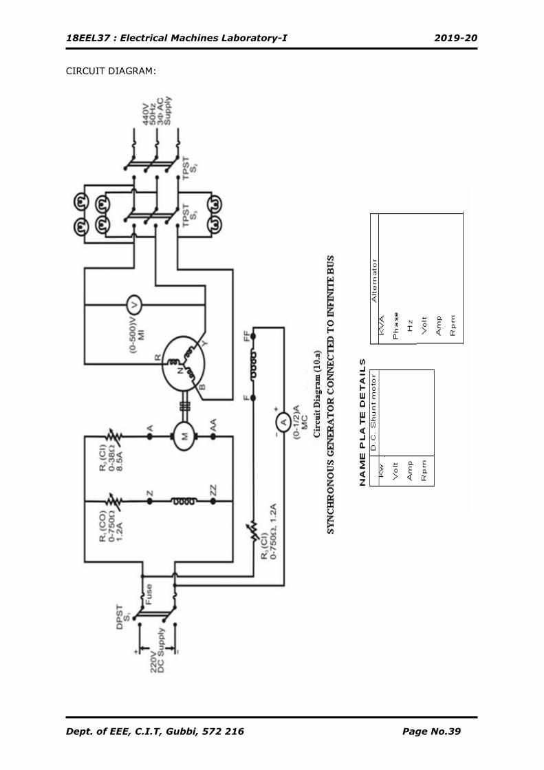
1. Connections are made as shown in the circuit diagram (9).
2. By keeping the 1-Ф auto-transformers (1) and (2) in zero out-put positions, SPST
switch (S3) and DPST switch (S2) in open positions, the supply switch (S1) is
closed.
3. Vary the 1-Ф auto-transformer no-(1) gradually and apply the rated voltage of
the transformer. [say 230V]
4. The reading of voltmeter (V2) connected across the SPST switch (S3) is observed.
It should read zero; if not, the auto-transformer is brought back to its initial zero
out-put position, open the supply switch (S1) and interchange one of the
transformer’s secondary terminals.
5. Close the supply switch (S1), repeat step no-3. Close SPST switch (S3). (By
ensuring voltmeter (V2) reads zero). The watt-meter (W0), voltmeter (V1) and
ammeter (I1) readings are noted down.
6. Switch (S2) is closed and by operating the auto-transformer (2) very slowly, a low
voltage is applied such that rated current flows through the transformer. The
wattmeter (WCU) and ammeter (I2) readings are noted down.
7. The auto-transformers (2) and then (1) are brought back to their initial zero out-
put positions, the DPST switch (S2), SPST switch (S3), and supply switch (S1) are
opened.
18EEL37 : Electrical Machines Laboratory-I 2019-20
Dept. of EEE, CIT-Gubbi, 572 216 Page No.37
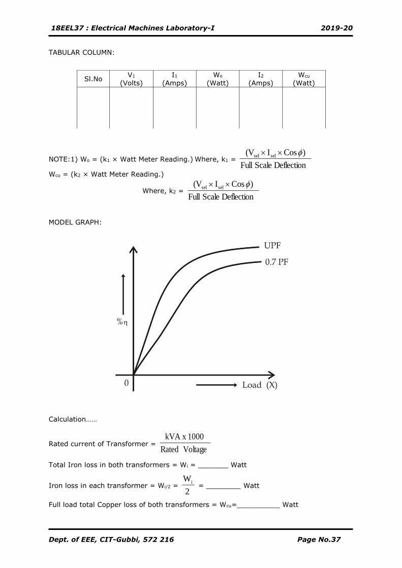
TABULAR COLUMN:
NOTE:1) Wo = (k1 × Watt Meter Reading.) Where, k1 = Deflection Scale Full
) CosI(V selsel
Wcu = (k2 × Watt Meter Reading.)
Where, k2 = Deflection Scale Full
) CosI(V selsel
MODEL GRAPH:
Calculation……
Rated current of Transformer = Voltage Rated
1000kVA x
Total Iron loss in both transformers = Wi = _______ Watt
Iron loss in each transformer = Wi/2 = 2
Wi = ________ Watt
Full load total Copper loss of both transformers = Wcu=__________ Watt
Sl.No V1
(Volts)
I1
(Amps)
Wo
(Watt)
I2
(Amps)
Wcu
(Watt)
18EEL37 : Electrical Machines Laboratory-I 2019-20
Dept. of EEE, CIT-Gubbi, 572 216 Page No.38
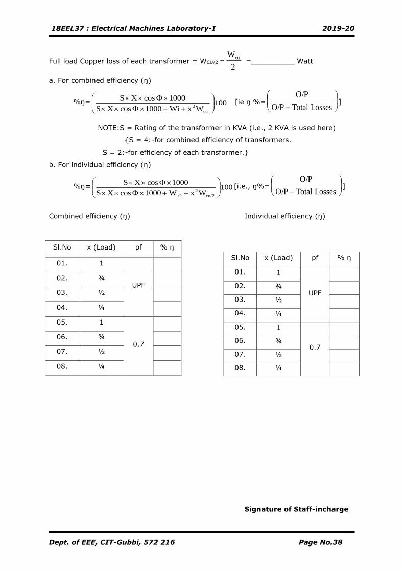
Full load Copper loss of each transformer = WCU/2 = 2
Wcu =__________ Watt
a. For combined efficiency (ŋ)
%ŋ= 100 WxWi1000 cosXS
1000 cosXS
cu
2
++
[ie ŋ %=
+ Losses TotalO/P
O/P]
NOTE:S = Rating of the transformer in KVA (i.e., 2 KVA is used here)
{S = 4:-for combined efficiency of transformers.
S = 2:-for efficiency of each transformer.}
b. For individual efficiency (ŋ)
%ŋ= 100 WxW1000 cosXS
1000 cosXS
cu/2
2
i/2
++
[i.e., ŋ%=
+ Losses TotalO/P
O/P]
Combined efficiency (ŋ) Individual efficiency (ŋ)
Signature of Staff-incharge
Sl.No x (Load) pf % ŋ
01. 1
UPF
02. ¾
03. ½
04. ¼
05. 1
0.7
06. ¾
07. ½
08. ¼
Sl.No x (Load) pf % ŋ
01. 1
UPF
02. ¾
03. ½
04. ¼
05. 1
0.7
06. ¾
07. ½
08. ¼
18EEL37 : Electrical Machines Laboratory-I 2019-20
Dept. of EEE, C.I.T, Gubbi, 572 216 Page No.39
CIRCUIT DIAGRAM:
18EEL37 : Electrical Machines Laboratory-I 2019-20
Dept. of EEE, C.I.T, Gubbi, 572 216 Page No.40
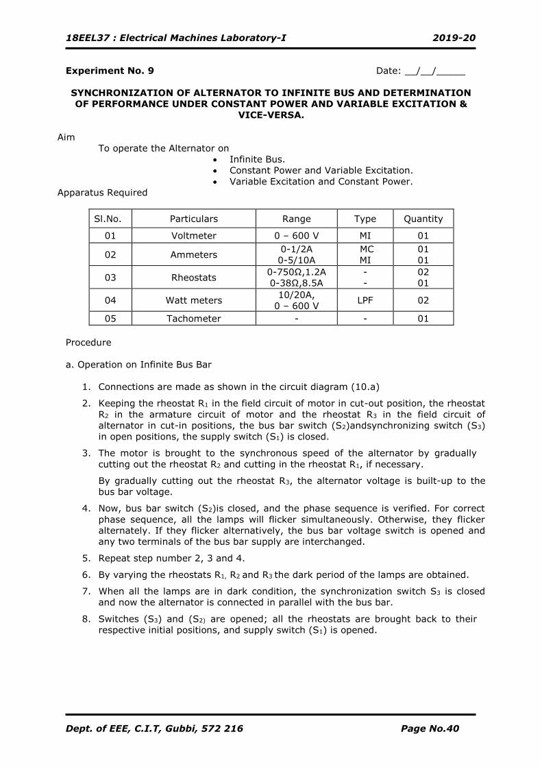
Experiment No. 9 Date: __/__/_____
SYNCHRONIZATION OF ALTERNATOR TO INFINITE BUS AND DETERMINATION
OF PERFORMANCE UNDER CONSTANT POWER AND VARIABLE EXCITATION &
VICE-VERSA.
Aim
To operate the Alternator on
• Infinite Bus.
• Constant Power and Variable Excitation.
• Variable Excitation and Constant Power.
Apparatus Required
Sl.No. Particulars Range Type Quantity
01 Voltmeter 0 – 600 V MI 01
02 Ammeters 0-1/2A
0-5/10A
MC
MI
01
01
03 Rheostats 0-750Ω,1.2A
0-38Ω,8.5A
-
-
02
01
04 Watt meters 10/20A,
0 – 600 V LPF 02
05 Tachometer - - 01
Procedure
a. Operation on Infinite Bus Bar
1. Connections are made as shown in the circuit diagram (10.a)
2. Keeping the rheostat R1 in the field circuit of motor in cut-out position, the rheostat
R2 in the armature circuit of motor and the rheostat R3 in the field circuit of
alternator in cut-in positions, the bus bar switch (S2)andsynchronizing switch (S3)
in open positions, the supply switch (S1) is closed.
3. The motor is brought to the synchronous speed of the alternator by gradually
cutting out the rheostat R2 and cutting in the rheostat R1, if necessary.
By gradually cutting out the rheostat R3, the alternator voltage is built-up to the
bus bar voltage.
4. Now, bus bar switch (S2)is closed, and the phase sequence is verified. For correct
phase sequence, all the lamps will flicker simultaneously. Otherwise, they flicker
alternately. If they flicker alternatively, the bus bar voltage switch is opened and
any two terminals of the bus bar supply are interchanged.
5. Repeat step number 2, 3 and 4.
6. By varying the rheostats R1, R2 and R3 the dark period of the lamps are obtained.
7. When all the lamps are in dark condition, the synchronization switch S3 is closed
and now the alternator is connected in parallel with the bus bar.
8. Switches (S3) and (S2) are opened; all the rheostats are brought back to their
respective initial positions, and supply switch (S1) is opened.
18EEL37 : Electrical Machines Laboratory-I 2019-20
Dept. of EEE, C.I.T, Gubbi, 572 216 Page No.41
18EEL37 : Electrical Machines Laboratory-I 2019-20
Dept. of EEE, C.I.T, Gubbi, 572 216 Page No.42
b. Constant Power - Variable Excitation Operation
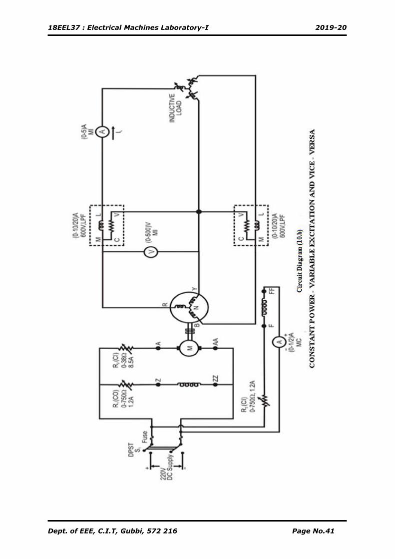
1. Connections are made as shown in the circuit diagram (10.b)
2. Follow the procedure steps 2, 3 of procedure (a)
3. By gradually cutting out the rheostat R3, the alternator voltage is built-up to its
rated voltage.
4. Apply load gradually.
5. Vary generator excitation (R3) to keep wattmeter readings constant (Total
Power).
6. Tabulate the readings.
7. Bring back the load to zero, reduce the excitation to a normal value and all
rheostats are brought back to respective initial positions & supply switch (S1)is
opened.
c. Constant Excitation - Variable Power Operation
1. Connections are made as shown in the circuit diagram (10.b)
2. Follow theprocedure steps 2, 3 of procedure (a).
3. By gradually cutting out the rheostat R3, the alternator voltage is built-up to its
rated voltage.
4. Apply load in steps & note down all meter readings (Excitation should be constant
by adjusting the speed of the Motor).
5. Bring back the load to zero, reduce the excitation to a normal value and all
rheostats are brought back to respective initial positions & supply switch (S1) is
opened.
18EEL37 : Electrical Machines Laboratory-I 2019-20
Dept. of EEE, C.I.T, Gubbi, 572 216 Page No.43
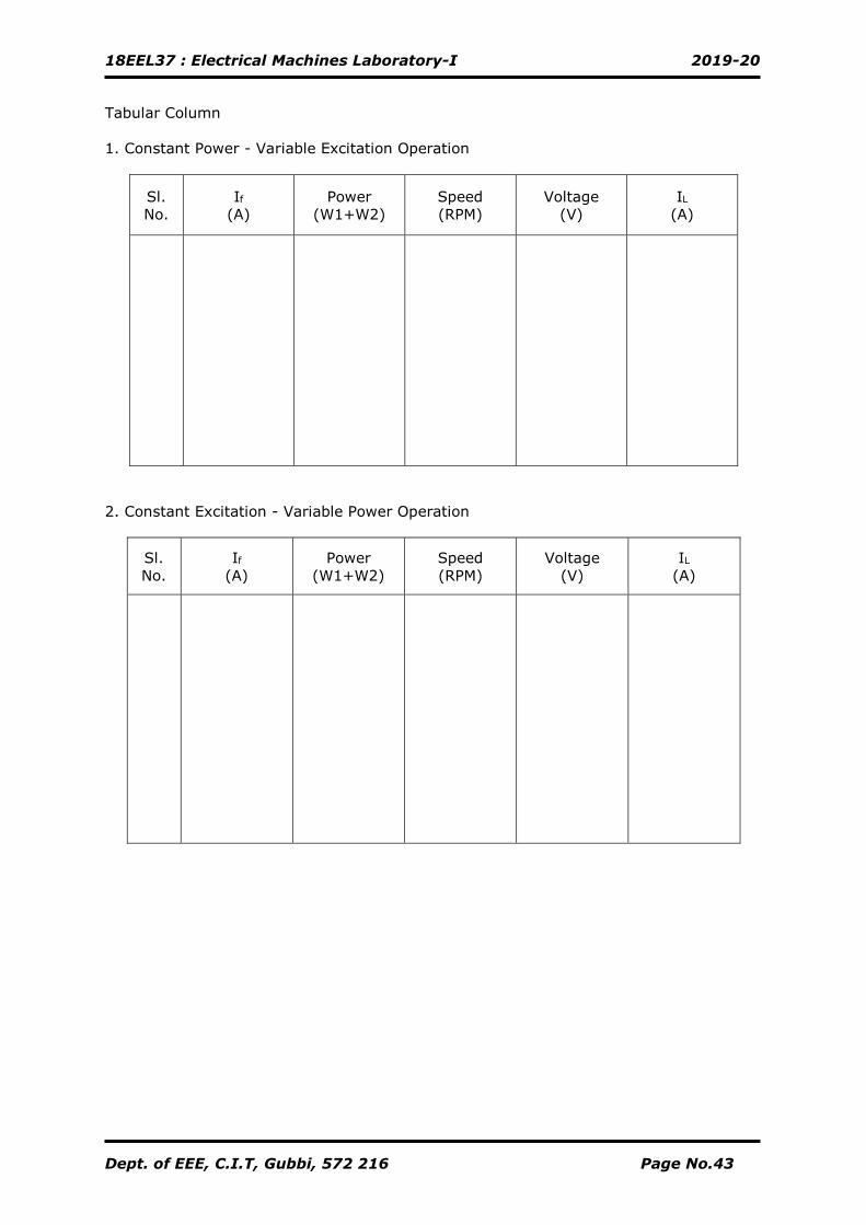
Tabular Column
1. Constant Power - Variable Excitation Operation
Sl.
No.
If
(A)
Power
(W1+W2)
Speed
(RPM)
Voltage
(V)
IL
(A)
2. Constant Excitation - Variable Power Operation
Sl.
No.
If
(A)
Power
(W1+W2)
Speed
(RPM)
Voltage
(V)
IL
(A)
18EEL37 : Electrical Machines Laboratory-I 2019-20
Dept. of EEE, C.I.T, Gubbi, 572 216 Page No.44
Calculation:
Signature of Staff-incharge
18EEL37 : Electrical Machines Laboratory-I 2019-20
Dept. of EEE, C.I.T, Gubbi, 572 216 Page No.45
CIRCUIT DIAGRAM:
Tabular Column
1. Open Circuit Test 2. Short Circuit Test
Sl.
No
If
Amps
V0 Volts
VL Vph
If Amps
ISC Amps
18EEL37 : Electrical Machines Laboratory-I 2019-20
Dept. of EEE, C.I.T, Gubbi, 572 216 Page No.46
Experiment No. 10 Date: __/__/_____
REGULATION OF ALTERNATOR BY ZPF METHOD
Aim
To determine the percentage regulation of an alternator by ZPF method or Potier
Triangle Method.
Apparatus Required
Sl.No Particulars Range Type Quantity
01. Voltmeter 0 – 600 V MI 01
02. Ammeters 0-10/20A
0-1/2A
MI
MC
01
01
03. Rheostats 0-750Ω,1.2A
0-38Ω,8.5A -
02
01
04. Watt meters 0 – 10/20 A,
0 – 600 V LPF 02
05. Tachometer - - 01
06. 3-phase
Inductive Load - - 01
Procedure
a. Open Circuit Test
1. Connections are made as shown in the circuit diagram (1.a)
2. Keeping the rheostat R1 in the field circuit of motor in cut-out position, the
rheostat R2 in the armature circuit of the motor and the rheostat R3 in field circuit
of the alternator in cut-in positions, and TPST (S2) in open position, the supply
switch (S1) is closed.
3. The motor is brought to synchronous speed by cutting out the rheostat R2 and
then by cutting in the rheostat R1, if necessary.
4. By gradually cutting out the rheostat R3, the readings of ammeter (A1, 0-2A) and
voltmeter (V) are noted down.
5. The above step is continued until voltmeter reads about 1.25 times the rated
voltage of the alternator.
b. Short Circuit Test
1. The rheostat R3 is brought to its initial position (cut-in) and TPST (S2) is closed.
2. By gradually cutting out the rheostat R3, reading of the ammeter (A2,0-10/20A) is
adjusted to the rated current of the alternator and the corresponding field current
(A1, 0-1/2A) is noted down.
3. All the rheostats are brought back to their respective initial positions, TPST switch
(S2) and supply switch (S1) are opened.
18EEL37 : Electrical Machines Laboratory-I 2019-20
Dept. of EEE, C.I.T, Gubbi, 572 216 Page No.47
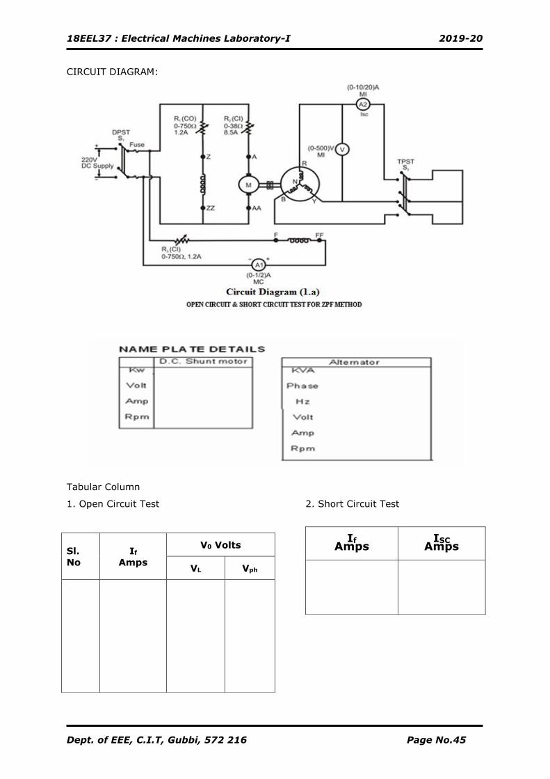
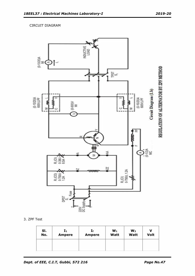
CIRCUIT DIAGRAM
3. ZPF Test
Sl.
No.
I1
Ampere
If
Ampere
W1
Watt
W2
Watt
V
Volt
18EEL37 : Electrical Machines Laboratory-I 2019-20
Dept. of EEE, C.I.T, Gubbi, 572 216 Page No.48
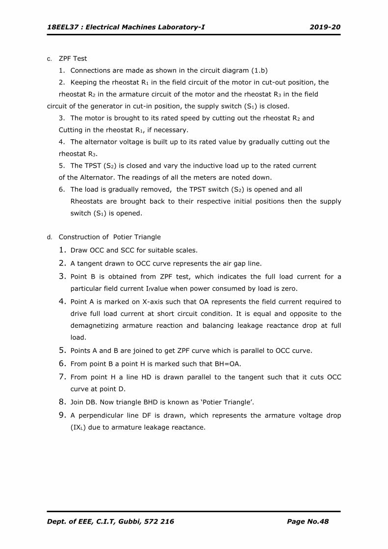
c. ZPF Test
1. Connections are made as shown in the circuit diagram (1.b)
2. Keeping the rheostat R1 in the field circuit of the motor in cut-out position, the
rheostat R2 in the armature circuit of the motor and the rheostat R3 in the field
circuit of the generator in cut-in position, the supply switch (S1) is closed.
3. The motor is brought to its rated speed by cutting out the rheostat R2 and
Cutting in the rheostat R1, if necessary.
4. The alternator voltage is built up to its rated value by gradually cutting out the
rheostat R3.
5. The TPST (S2) is closed and vary the inductive load up to the rated current
of the Alternator. The readings of all the meters are noted down.
6. The load is gradually removed, the TPST switch (S2) is opened and all
Rheostats are brought back to their respective initial positions then the supply
switch (S1) is opened.
d. Construction of Potier Triangle
1. Draw OCC and SCC for suitable scales.
2. A tangent drawn to OCC curve represents the air gap line.
3. Point B is obtained from ZPF test, which indicates the full load current for a
particular field current Ifvalue when power consumed by load is zero.
4. Point A is marked on X-axis such that OA represents the field current required to
drive full load current at short circuit condition. It is equal and opposite to the
demagnetizing armature reaction and balancing leakage reactance drop at full
load.
5. Points A and B are joined to get ZPF curve which is parallel to OCC curve.
6. From point B a point H is marked such that BH=OA.
7. From point H a line HD is drawn parallel to the tangent such that it cuts OCC
curve at point D.
8. Join DB. Now triangle BHD is known as ‘Potier Triangle’.
9. A perpendicular line DF is drawn, which represents the armature voltage drop
(IXL) due to armature leakage reactance.
18EEL37 : Electrical Machines Laboratory-I 2019-20
Dept. of EEE, C.I.T, Gubbi, 572 216 Page No.49
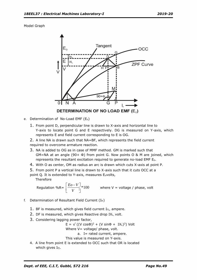
Model Graph
e. Determination of No-Load EMF (Eo)
1. From point D, perpendicular line is drawn to X-axis and horizontal line to
Y-axis to locate point G and E respectively. DG is measured on Y-axis, which
represents E and field current corresponding to E is OG.
2. A line NA is drawn such that NA=BF, which represents the field current
required to overcome armature reaction.
3. NA is added to OG as in case of MMF method. GM is marked such that
GM=NA at an angle (90+ Ф) from point G. Now points O & M are joined, which
represents the resultant excitation required to generate no-load EMF Eo.
4. With O as center, OM as radius an arc is drawn which cuts X-axis at point P.
5. From point P a vertical line is drawn to X-axis such that it cuts OCC at a
point Q. It is extended to Y-axis, measures Eovolts,
Therefore
Regulation %R= 100*
−
V
VEo where V = voltage / phase, volt
f. Determination of Resultant Field Current (Ifr)
1. BF is measured, which gives field current If1, ampere.
2. DF is measured, which gives Reactive drop IXL, volt.
3. Considering lagging power factor,
E = √ ((V cosФ)2 + (V sinФ + IXL)2) Volt
Where V= voltage/ phase, volt.
a. I= rated current, ampere.
This value is measured on Y-axis.
4. A line from point E is extended to OCC such that OR is located
which gives If2.
18EEL37 : Electrical Machines Laboratory-I 2019-20
Dept. of EEE, C.I.T, Gubbi, 572 216 Page No.50
Therefore resultant field current is given by
Ifr = √ (If22 + If1
2 +2 If1 If2cosӨ) Ampere.
CALCULATION:
Signature of Staff-incharge
18EEL37 : Electrical Machines Laboratory-I 2019-20
Dept. of EEE, C.I.T, Gubbi, 572 216 Page No.51
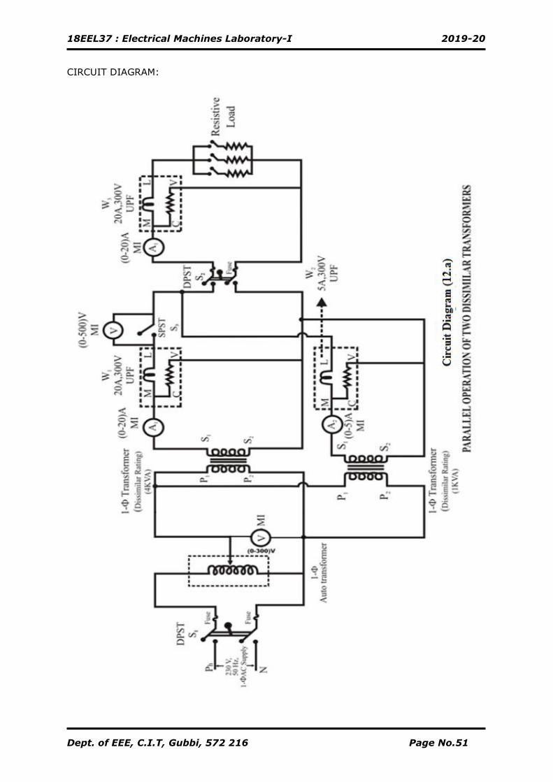
CIRCUIT DIAGRAM:
18EEL37 : Electrical Machines Laboratory-I 2019-20
Dept. of EEE, C.I.T, Gubbi, 572 216 Page No.52
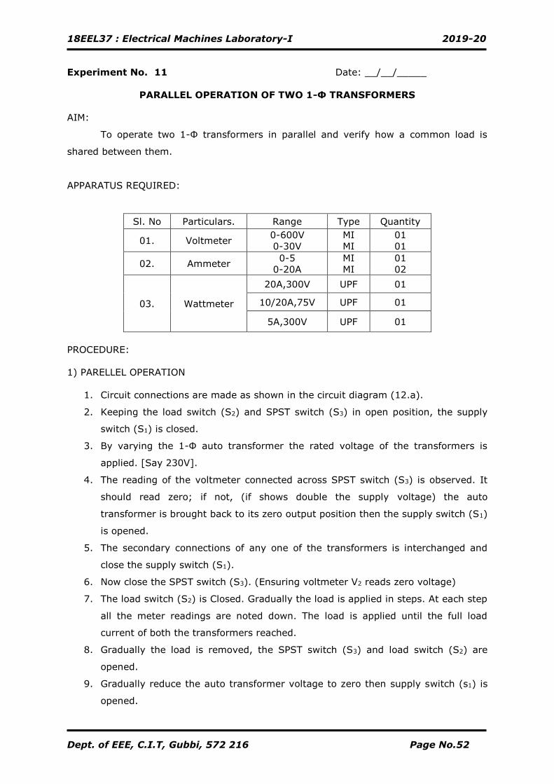
Experiment No. 11 Date: __/__/_____
PARALLEL OPERATION OF TWO 1-Ф TRANSFORMERS
AIM:
To operate two 1-Ф transformers in parallel and verify how a common load is
shared between them.
APPARATUS REQUIRED:
Sl. No Particulars. Range Type Quantity
01. Voltmeter 0-600V
0-30V
MI
MI
01
01
02. Ammeter 0-5
0-20A
MI
MI
01
02
03. Wattmeter
20A,300V UPF 01
10/20A,75V UPF 01
5A,300V UPF 01
PROCEDURE:
1) PARELLEL OPERATION
1. Circuit connections are made as shown in the circuit diagram (12.a).
2. Keeping the load switch (S2) and SPST switch (S3) in open position, the supply
switch (S1) is closed.
3. By varying the 1-Ф auto transformer the rated voltage of the transformers is
applied. [Say 230V].
4. The reading of the voltmeter connected across SPST switch (S3) is observed. It
should read zero; if not, (if shows double the supply voltage) the auto
transformer is brought back to its zero output position then the supply switch (S1)
is opened.
5. The secondary connections of any one of the transformers is interchanged and
close the supply switch (S1).
6. Now close the SPST switch (S3). (Ensuring voltmeter V2 reads zero voltage)
7. The load switch (S2) is Closed. Gradually the load is applied in steps. At each step
all the meter readings are noted down. The load is applied until the full load
current of both the transformers reached.
8. Gradually the load is removed, the SPST switch (S3) and load switch (S2) are
opened.
9. Gradually reduce the auto transformer voltage to zero then supply switch (s1) is
opened.
18EEL37 : Electrical Machines Laboratory-I 2019-20
Dept. of EEE, C.I.T, Gubbi, 572 216 Page No.53
TABULAR COLUMN:
1. PARELLEL OPERATION
2. SHORT CIRCUIT TEST
Transformer Isc Wsc Vsc Remarks
1.
2 KVA
2.
1 KVA
NOTE: 1)W1 = (k1 × Watt Meter Reading.) Where, k1= Deflection Scale Full
) CosI(V selsel
W2 = (k1 × Watt Meter Reading.) Where, k2= Deflection Scale Full
) CosI(V selsel
W3 = (k3 × Watt Meter Reading.) Where, k3 = Deflection Scale Full
) CosI(V selsel
Wsc = (k4 × Watt Meter Reading.) Where, ksc = Deflection Scale Full
) CosI(V selsel
Sl.
No
W1
(Watt)
W2
(Watt)
W3
(Watt)
I1
(Amps)
I2
(Amps) I3
(Amps) Actual Theoretical Actual Theoretical
18EEL37 : Electrical Machines Laboratory-I 2019-20
Dept. of EEE, C.I.T, Gubbi, 572 216 Page No.54
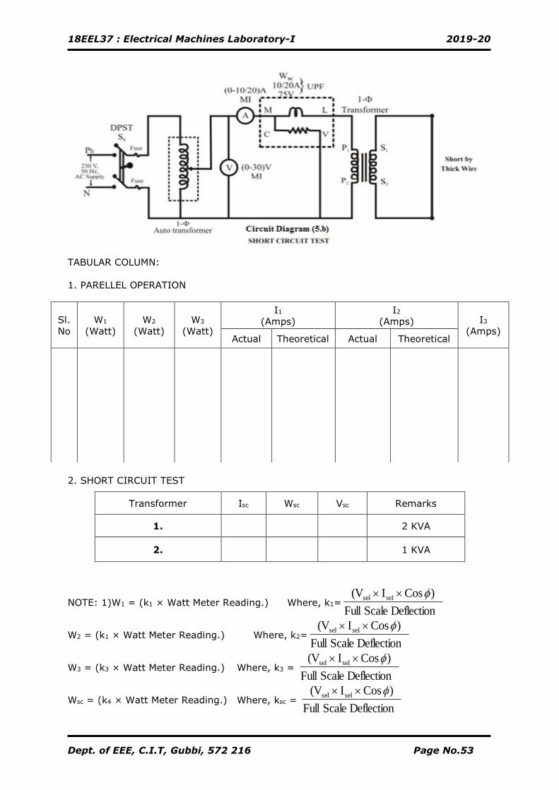
2) SHORT CIRCUIT TEST
1. Connections are made as shown in the circuit diagram (12.b).
2. Keeping 1-Ф auto-transformer voltage in zero out-put position, the supply switch
(S1) is closed.
3. By varying the 1-Ф auto transformer voltage very slowly, a low voltage is applied
such that rated current flows through the transformer.
4. The readings of all the meters are noted down.
5. The auto-transformer is brought back to its initial zero output position, the supply
switch (S1) is opened.
6. The above steps are repeated for another transformer.
CALCULATION:
1. For Transformer I (4 KVA)
Z01 =
SC
SC
I
VΩ = R01 = Ω = X01=
2
1
2
1 RZ − Ω=
2. For Transformer II (1 KVA)
Z02 =
SC
SC
I
VΩ = R02 = Ω = X02 =
2
2
2
2 RZ − Ω=
THEORETICAL CALCULATION:
I1 =
0201
023
ZZ
ZI
+ =
( ) ( )2
0201
2
0201
2
02
2
023
XXRR
XRI
+++
+ Amps
I2 =
0201
013
ZZ
ZI
+ =
( ) ( )2
0201
2
0201
2
01
2
013
XXRR
XRI
+++
+ Amps
Calculation………..
Signature of Staff-incharge
2
SC
SC
I
W
2
SC
SC
I
W
18EEL37 : Electrical Machines Laboratory-I 2019-20
Dept. of EEE, C.I.T, Gubbi, 572 216 Page No.55
CIRCUIT DIAGRAM:
Tabular Column
1. Open Circuit Test 2. Short Circuit Test
Sl.No If Amps V0 Volts
VL Vph
Sl.No If Amps IscAmps
18EEL37 : Electrical Machines Laboratory-I 2019-20
Dept. of EEE, C.I.T, Gubbi, 572 216 Page No.56
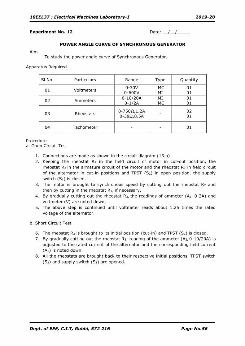
Experiment No. 12 Date: __/__/_____
POWER ANGLE CURVE OF SYNCHRONOUS GENERATOR
Aim
To study the power angle curve of Synchronous Generator.
Apparatus Required
Sl.No Particulars Range Type Quantity
01 Voltmeters 0-30V
0-600V
MC
MI
01
01
02 Ammeters 0-10/20A
0-1/2A
MI
MC
01
01
03 Rheostats 0-750Ω,1.2A
0-38Ω,8.5A -
02
01
04 Tachometer - - 01
Procedure
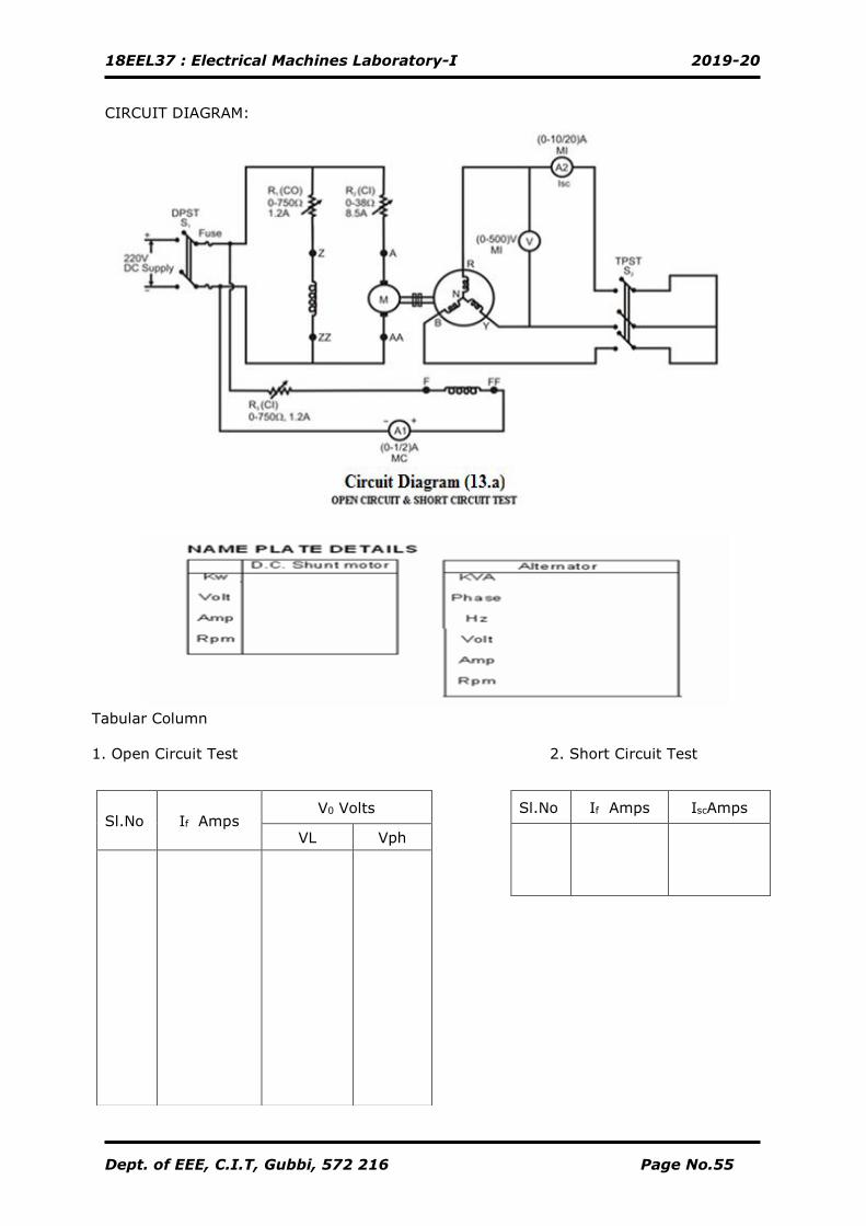
a. Open Circuit Test
1. Connections are made as shown in the circuit diagram (13.a)
2. Keeping the rheostat R1 in the field circuit of motor in cut-out position, the
rheostat R2 in the armature circuit of the motor and the rheostat R3 in field circuit
of the alternator in cut-in positions and TPST (S2) in open position, the supply
switch (S1) is closed.
3. The motor is brought to synchronous speed by cutting out the rheostat R2 and
then by cutting in the rheostat R1, if necessary.
4. By gradually cutting out the rheostat R3, the readings of ammeter (A1, 0-2A) and
voltmeter (V) are noted down.
5. The above step is continued until voltmeter reads about 1.25 times the rated
voltage of the alternator.
b. Short Circuit Test
6. The rheostat R3 is brought to its initial position (cut-in) and TPST (S2) is closed.
7. By gradually cutting out the rheostat R3, reading of the ammeter (A2, 0-10/20A) is
adjusted to the rated current of the alternator and the corresponding field current
(A1) is noted down.
8. All the rheostats are brought back to their respective initial positions, TPST switch
(S2) and supply switch (S1) are opened.
18EEL37 : Electrical Machines Laboratory-I 2019-20
Dept. of EEE, C.I.T, Gubbi, 572 216 Page No.57
Determination of Stator Resistance of Alternator (Ra)
Sl.No V
(Volts)
I
(Ampere)
Resistance
RDC = V/I Ω
Resistance
RAC =1.5*RDC
18EEL37 : Electrical Machines Laboratory-I 2019-20
Dept. of EEE, C.I.T, Gubbi, 572 216 Page No.58
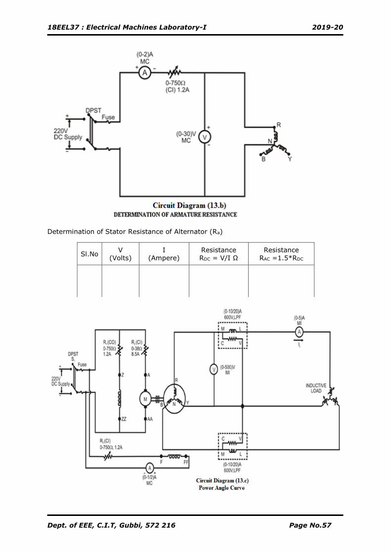
Determination of Armature Resistance (Ra) by V-I Method
9. Connections are made as shown in the circuit diagram (13.b)
10. Keeping the rheostat in cut-in position, the supply switch (S1) is closed, Rheostat
is adjusted to any value of current (say 1A) and the readings of ammeter and
voltmeter are noted down.
11. The supply switch (S1) is opened.
Power angle curve
1. Connections are made as shown in the circuit diagram (13.c)
2. Follow theprocedure steps 2, 3 of procedure (a).
3. By gradually cutting out the rheostat R3, the alternator voltage is built-up to its
rated voltage.
4. Apply load in steps & note down all meter readings (Excitation should be constant
by adjusting the speed of the Motor).
5. Bring back the load to zero, reduce the excitation to a normal value and all
rheostats are brought back to respective initial positions & supply switch (S1) is
opened.
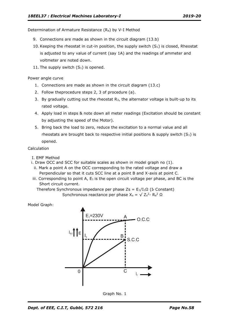
Calculation
I. EMF Method
i. Draw OCC and SCC for suitable scales as shown in model graph no (1).
ii. Mark a point A on the OCC corresponding to the rated voltage and draw a
Perpendicular so that it cuts SCC line at a point B and X-axis at point C.
iii. Corresponding to point A, E1 is the open circuit voltage per phase, and BC is the
Short circuit current.
Therefore Synchronous impedance per phase Zs = E1/I1Ω (If Constant)
Synchronous reactance per phase Xs = √ Zs2- Ra
2 Ω
Model Graph:
Graph No. 1
18EEL37 : Electrical Machines Laboratory-I 2019-20
Dept. of EEE, C.I.T, Gubbi, 572 216 Page No.59
Sl. No.
If (Amps)
Ia (Amps)
W1 x K1 (Watt)
W2 x K2 (Watt)
N (rpm) |V|
(Volts) |E|
(Volts) P = W1 + W2
(Watt) δ
Degree
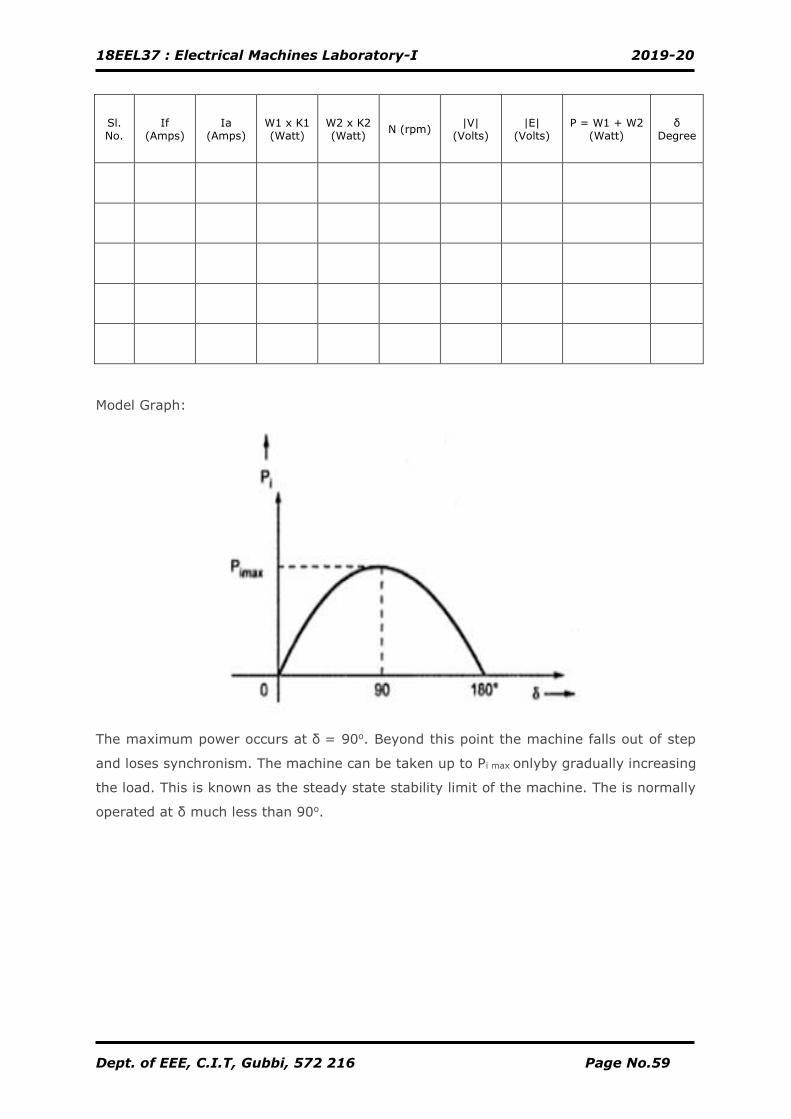
Model Graph:
The maximum power occurs at δ = 90o. Beyond this point the machine falls out of step
and loses synchronism. The machine can be taken up to Pi max onlyby gradually increasing
the load. This is known as the steady state stability limit of the machine. The is normally
operated at δ much less than 90o.
18EEL37 : Electrical Machines Laboratory-I 2019-20
Dept. of EEE, C.I.T, Gubbi, 572 216 Page No.60
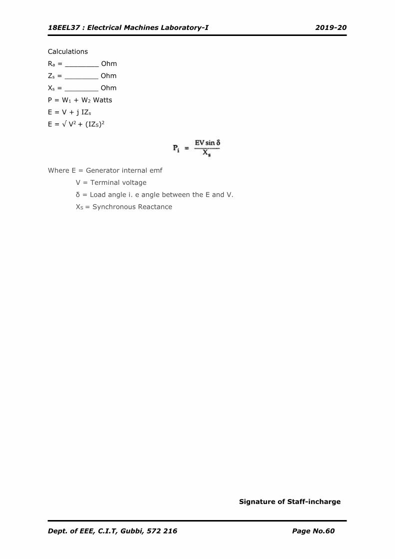
Calculations
Ra = ________ Ohm
Zs = ________ Ohm
Xs = ________ Ohm
P = W1 + W2 Watts
E = V + j IZs
E = √ V2 + (IZS)2
Where E = Generator internal emf
V = Terminal voltage
δ = Load angle i. e angle between the E and V.
XS = Synchronous Reactance
Signature of Staff-incharge
18EEL37 : Electrical Machines Laboratory-I 2019-20
Dept. of EEE, C.I.T, Gubbi, 572 216 Page No.61
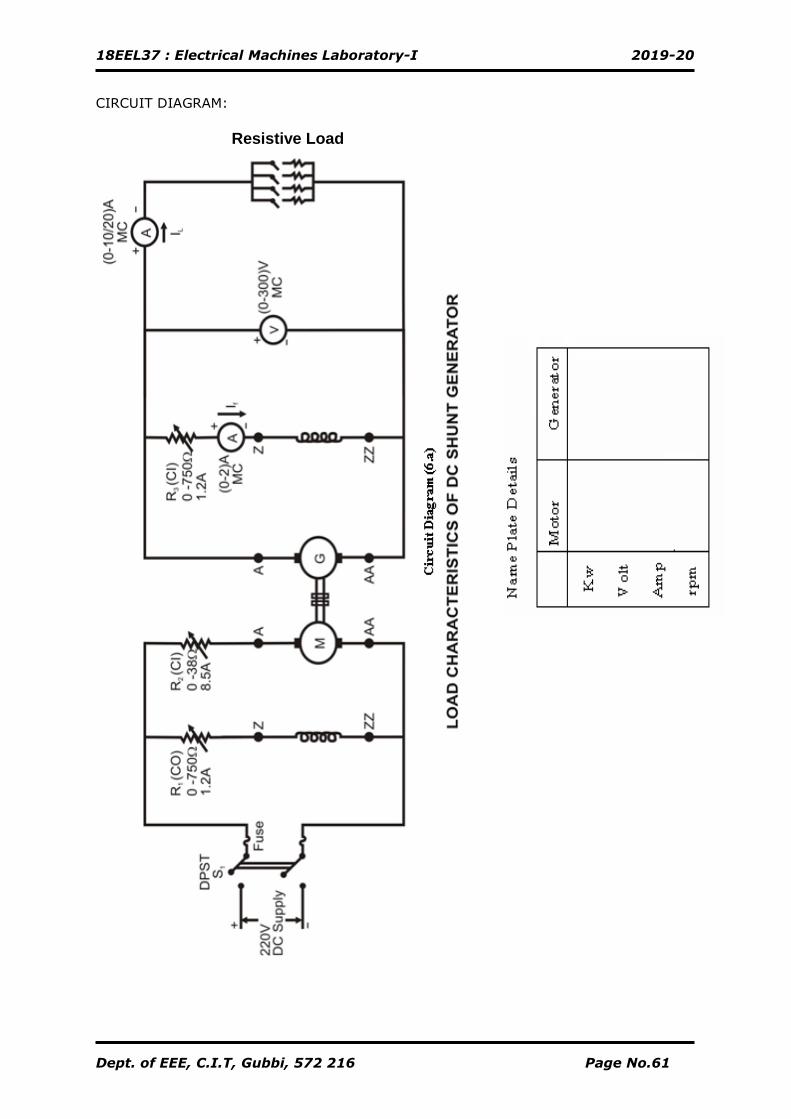
CIRCUIT DIAGRAM:
Resistive Load
18EEL37 : Electrical Machines Laboratory-I 2019-20
Dept. of EEE, C.I.T, Gubbi, 572 216 Page No.62
ADDITIONAL EXPERIMENT
NO-LOAD AND LOAD CHARACTERISTICS OF A DC-SHUNT GENERATOR
Aim:
To draw the external and internal characteristics of the given D.C shunt
generator.
Apparatus Required:
Procedure
A. NO- LOAD CHARACTERISTICS
1. Connections are made as shown in the circuit diagram (6.a).
2. Keeping the rheostat R1 in the field circuit of the motor in cut-out position, the
rheostat R2 in the armature circuit of the motor and the rheostat R3 in the field
circuit of the generator in cut-in positions, and all load switches in off condition,
the supply switch (S1) is closed, the motors starts rotating.
3. The motor is brought to its rated speed by gradually cutting out rheostat
R2completelyand cutting in the rheostat R1, if necessary.
4. The generator voltage is built in steps up to its rated value by gradually cutting-
out rheostat R3.
5. Note down the corresponding generated voltage and field currents in steps. Plot
the graph.
B. LOAD CHARACTERISTICS
1. Connections are made as shown in the circuit diagram (6.a).
2. Keeping the rheostat R1 in the field circuit of the motor in cut-out position, the
rheostat R2 in the armature circuit of the motor and the rheostat R3 in the field
circuit of the generator in cut-in positions, and all load switches in off condition,
the supply switch (S1) is closed, the motors starts rotating.
3. The motor is brought to its rated speed by gradually cutting out rheostat R2
completelyand cutting in the rheostat R1, if necessary.
4. The generator voltage is built up to its rated value by gradually cutting-out
rheostat R3.
Sl.
No. Particulars Range Type Quantity
01 Voltmeters 0-300V
0-30V
MC
MC
01
01
02 Ammeters 0-10/20 A
0-1/2A
MC
MC
01
01
03 Rheostats 0-750Ω,1.2A
0-38Ω, 8.5A
-
-
02
01
04 Tachometer - - 01
18EEL37 : Electrical Machines Laboratory-I 2019-20
Dept. of EEE, C.I.T, Gubbi, 572 216 Page No.63
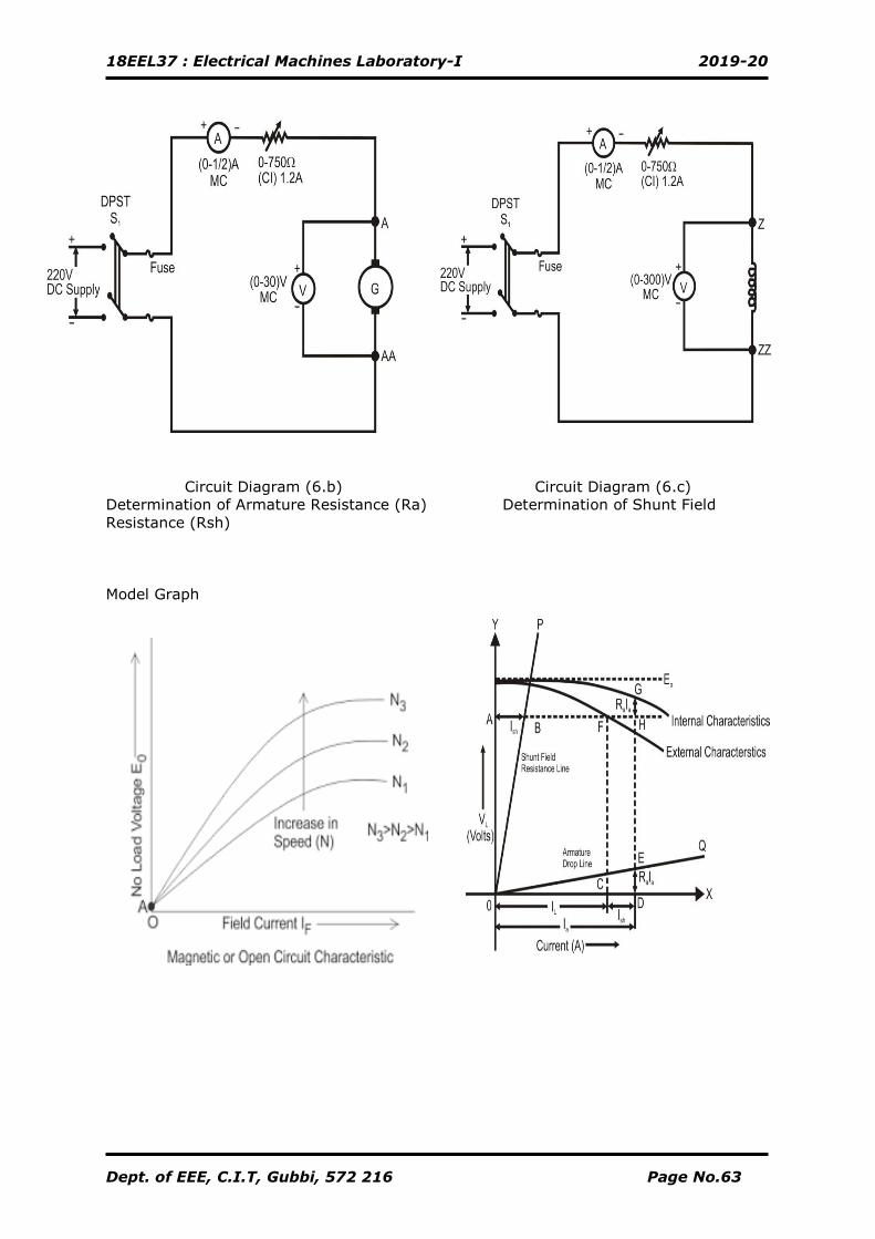
Circuit Diagram (6.b) Circuit Diagram (6.c)
Determination of Armature Resistance (Ra) Determination of Shunt Field
Resistance (Rsh)
Model Graph
18EEL37 : Electrical Machines Laboratory-I 2019-20
Dept. of EEE, C.I.T, Gubbi, 572 216 Page No.64
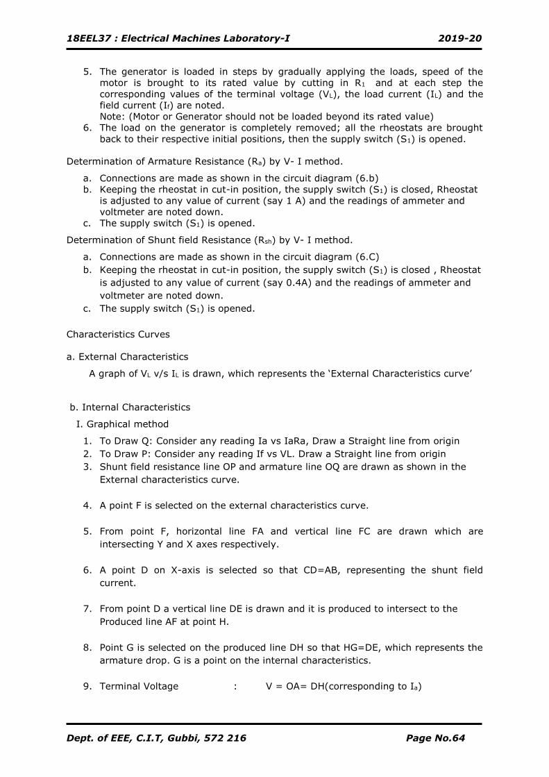
5. The generator is loaded in steps by gradually applying the loads, speed of the
motor is brought to its rated value by cutting in R1 and at each step the
corresponding values of the terminal voltage (VL), the load current (IL) and the
field current (If) are noted.
Note: (Motor or Generator should not be loaded beyond its rated value)
6. The load on the generator is completely removed; all the rheostats are brought
back to their respective initial positions, then the supply switch (S1) is opened.
Determination of Armature Resistance (Ra) by V- I method.
a. Connections are made as shown in the circuit diagram (6.b)
b. Keeping the rheostat in cut-in position, the supply switch (S1) is closed, Rheostat
is adjusted to any value of current (say 1 A) and the readings of ammeter and
voltmeter are noted down.
c. The supply switch (S1) is opened.
Determination of Shunt field Resistance (Rsh) by V- I method.
a. Connections are made as shown in the circuit diagram (6.C)
b. Keeping the rheostat in cut-in position, the supply switch (S1) is closed , Rheostat
is adjusted to any value of current (say 0.4A) and the readings of ammeter and
voltmeter are noted down.
c. The supply switch (S1) is opened.
Characteristics Curves
a. External Characteristics
A graph of VL v/s IL is drawn, which represents the ‘External Characteristics curve’
b. Internal Characteristics
I. Graphical method
1. To Draw Q: Consider any reading Ia vs IaRa, Draw a Straight line from origin
2. To Draw P: Consider any reading If vs VL. Draw a Straight line from origin
3. Shunt field resistance line OP and armature line OQ are drawn as shown in the
External characteristics curve.
4. A point F is selected on the external characteristics curve.
5. From point F, horizontal line FA and vertical line FC are drawn which are
intersecting Y and X axes respectively.
6. A point D on X-axis is selected so that CD=AB, representing the shunt field
current.
7. From point D a vertical line DE is drawn and it is produced to intersect to the
Produced line AF at point H.
8. Point G is selected on the produced line DH so that HG=DE, which represents the
armature drop. G is a point on the internal characteristics.
9. Terminal Voltage : V = OA= DH(corresponding to Ia)
18EEL37 : Electrical Machines Laboratory-I 2019-20
Dept. of EEE, C.I.T, Gubbi, 572 216 Page No.65
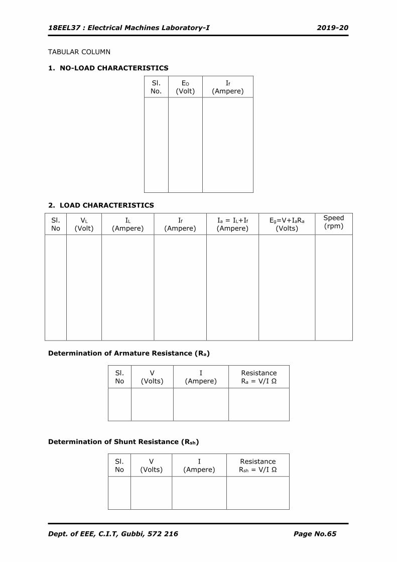
TABULAR COLUMN
1. NO-LOAD CHARACTERISTICS
Sl.
No.
EO
(Volt)
If
(Ampere)
2. LOAD CHARACTERISTICS
Sl.
No
VL
(Volt)
IL
(Ampere)
If
(Ampere)
Ia = IL+If
(Ampere)
Eg=V+IaRa
(Volts)
Speed
(rpm)
Determination of Armature Resistance (Ra)
Sl.
No
V
(Volts)
I
(Ampere)
Resistance
Ra = V/I Ω
Determination of Shunt Resistance (Rsh)
Sl.
No
V
(Volts)
I
(Ampere)
Resistance
Rsh = V/I Ω
18EEL37 : Electrical Machines Laboratory-I 2019-20
Dept. of EEE, C.I.T, Gubbi, 572 216 Page No.66
10. Armature Voltage Drop : Ia Ra = DE
11. Therefore EMF generated after allowing for the drop due to armature reaction:
Eg = V + Ia Ra volt
= DH+DE
=DH+HG (where HG=DE)
=DG
GK is the drop due to armature reaction
12. Similarly some more points are located on the external characteristics curve and
corresponding points on internal characteristics are determined.
13. A curve is drawn passing through these points, which represents ‘Internal
characteristics Curve’.
II. Analytical Method
Armature Current: Ia = IL + Ish Amps
EMF Generated :Eg=V + Ia Ra Volts
A graph of Eg v/s Ia is drawn, which represents ‘Internal characteristics’.
Calculation:
18EEL37 : Electrical Machines Laboratory-I 2019-20
Dept. of EEE, C.I.T, Gubbi, 572 216 Page No.67
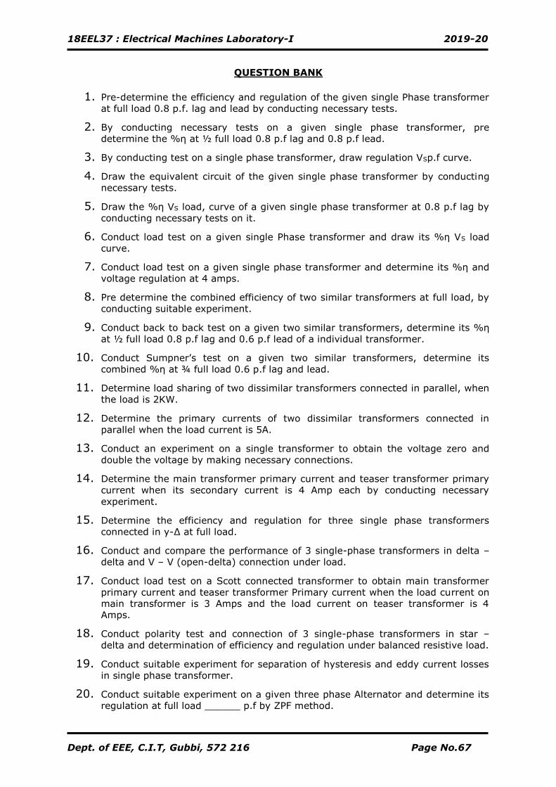
QUESTION BANK
1. Pre-determine the efficiency and regulation of the given single Phase transformer
at full load 0.8 p.f. lag and lead by conducting necessary tests.
2. By conducting necessary tests on a given single phase transformer, pre
determine the %η at ½ full load 0.8 p.f lag and 0.8 p.f lead.
3. By conducting test on a single phase transformer, draw regulation VSp.f curve.
4. Draw the equivalent circuit of the given single phase transformer by conducting
necessary tests.
5. Draw the %η VS load, curve of a given single phase transformer at 0.8 p.f lag by
conducting necessary tests on it.
6. Conduct load test on a given single Phase transformer and draw its %η VS load
curve.
7. Conduct load test on a given single phase transformer and determine its %η and
voltage regulation at 4 amps.
8. Pre determine the combined efficiency of two similar transformers at full load, by
conducting suitable experiment.
9. Conduct back to back test on a given two similar transformers, determine its %η
at ½ full load 0.8 p.f lag and 0.6 p.f lead of a individual transformer.
10. Conduct Sumpner’s test on a given two similar transformers, determine its
combined %η at ¾ full load 0.6 p.f lag and lead.
11. Determine load sharing of two dissimilar transformers connected in parallel, when
the load is 2KW.
12. Determine the primary currents of two dissimilar transformers connected in
parallel when the load current is 5A.
13. Conduct an experiment on a single transformer to obtain the voltage zero and
double the voltage by making necessary connections.
14. Determine the main transformer primary current and teaser transformer primary
current when its secondary current is 4 Amp each by conducting necessary
experiment.
15. Determine the efficiency and regulation for three single phase transformers
connected in y-∆ at full load.
16. Conduct and compare the performance of 3 single-phase transformers in delta –
delta and V – V (open-delta) connection under load.
17. Conduct load test on a Scott connected transformer to obtain main transformer
primary current and teaser transformer Primary current when the load current on
main transformer is 3 Amps and the load current on teaser transformer is 4
Amps.
18. Conduct polarity test and connection of 3 single-phase transformers in star –
delta and determination of efficiency and regulation under balanced resistive load.
19. Conduct suitable experiment for separation of hysteresis and eddy current losses
in single phase transformer.
20. Conduct suitable experiment on a given three phase Alternator and determine its
regulation at full load ______ p.f by ZPF method.
18EEL37 : Electrical Machines Laboratory-I 2019-20
Dept. of EEE, C.I.T, Gubbi, 572 216 Page No.68
21. By conducting suitable experiment, Pre determine the regulation of the given
three phase Alternator by EMF method at full load p.f ___________ (lag/lead)
22. By conducting suitable experiment, Pre determine the Regulation of the given
three phase Alternator by MMF method at full load p.f ___________ (lag/lead)
23. By conducting suitable experiments on the given three phase alternator to find its
Synchronous reactance.
24. By conducting suitable experiments on the given three phase alternator, find the
Potier reactance.
25. By conducting suitable experiment to Pre determine the regulation of the given
three phase Alternator by Potier Triangle method at full load p.f ____________
(lag/lead).
26. By conducting suitable experiment on the given salient pole alternator, pre-
determine the regulation at full load p.f _____________ (lag/lead).
27. Conduct a suitable experiment to measure the direct and quadrature axis
reactance and predetermination of regulation of salient pole synchronous
machines.
28. By conducting suitable experiment synchronize a 3phase Alternator to Infinite
Bus-bar.
29. Conduct a suitable experiment to operate the given three Phase alternator on
Constant power and variable excitation.
30. Conduct a suitable experiment to operate the given three phase alternator on
Constant excitation and variable power.
31. Obtain the following performance characteristics of the given DC Shunt Generator
by conducting suitable experiment. Determine the induced emf at __________
load. (Graphically/ Analytically) a. Internal Characteristics
32. Obtain the following performance characteristics of the given DC Shunt Generator
by conducting suitable experiment. a. External Characteristics b. Internal
Characteristics and determine the induced emf at __________ load.
33. Conduct a suitable experiment to obtain the no load and load characteristics of
DC Shunt generator.
!!!!!!! WISH YOU ALL THE BEST!!!!!!
18EEL37 : Electrical Machines Laboratory-I 2019-20
Dept. of EEE, C.I.T, Gubbi, 572 216 Page No.69
VIVA – VOCE QUESTIONS
1. What is the basic principle of operation of a single phase transformer?
2. What are the losses in a transformer?
3. Why the efficiency of transformer is higher than the rotating machines?
4. At full load, copper loss = 80 Watt and Iron loss =30 Watt. What will be the
values of copper loss and Iron loss at half load?
5. What is regulation of a transformer?
6. For a good transformer regulation should be low or high.
7. What information you will get by conducting O.C & S.C tests?
8. What do you mean by predetermination of efficiency and regulation of a
transformer?
9. What happens if the primary of the transformer is excited by a D.C source?
10. What is the condition for maximum efficiency?
11. Why Sumpner’s test is also called as ‘back – to back’ test?
12. Why does the test needs two identical transformers?
13. What information you will get by conducting this test?
14. What is the advantage of this test?
15. What are the limitations of this test?
16. Distinguish between commercial efficiency and all day efficiency.
17. Parallel Operation of Two single Phase Transformers
18. What are conditions to be satisfied for parallel operation of single phase
transformers?
19. What is the necessity of paralleling transformers?
20. How two transformers share the common load?
21. What is meant by circulating current with respect to parallel operation of
transformers?
22. Separation of Losses in a Single Phase transformer
23. What are the sources of heat in a power transformer?
24. Why the transformer core is laminated? Give Reasons?
25. How does Hysteresis loss and Eddy current loss take place in a magnetic
material?
26. What is polarity test?
27. What is the necessity of polarity test?
18EEL37 : Electrical Machines Laboratory-I 2019-20
Dept. of EEE, C.I.T, Gubbi, 572 216 Page No.70
28. What is the effect of current and voltage in Star – Delta Connection?
29. Where the star – delta connection applicable?
30. What happens if resistive load is replaced by capacitive or inductive load?
31. How 2- phase supply can be obtained from 3- phase supply?
32. How many transformers are used in Scott connection? Name them.
33. Draw the vector diagram for Scott connection.
34. Distinguish between an Auto-transformer and a two winding transformer.
35. Write down the equation for frequency of emf induced in an Alternator.
36. Name the types of Alternator based on their rotor construction.
37. Which type of Synchronous generators are used in Hydro-electric plants and
why?
38. What are the advantages of salient pole type construction used for
Synchronous machines?
39. Why is the stator core of Alternator laminated?
40. What are the causes of changes in voltage in Alternators when loaded?
41. Define the term voltage regulation.
42. State the condition to be satisfied before connecting two alternators in
parallel.
43. What is meant by infinite bus-bars?
44. How do the synchronizing lamps indicate the correctness of phase
sequencebetween existing and incoming Alternators?
45. Why are Alternators rated in kVA and not in kW?
18EEL37 : Electrical Machines Laboratory-I 2019-20
Dept. of EEE, C.I.T, Gubbi, 572 216 Page No.71
References
1. Electric Machinery by A. E. Fitzgerald, Charles Kingsley Jr. & Stephen Umans
2. Electric Machinery and Transformers (The Oxford Series in Electrical and
Computer Engineering) by Bhag S. Guru and Hüseyin R. Hiziroglu (Jul 20, 2000)
3. The performance and design of alternating current machines BY M.G.SAY, Third
Edition, CBS Publishers & Distributors
4. Transformers by BHEL, Bhopal (MP) TATA MCGRAW HILL.
5. Electrical Machinery by Dr.P.S.Bimbhra, Kanna Publisher
6. Theory of Alternating Current Machinery, Alexander S. Langsdorf TATA MCGRAW
HILL.
7. Electrical Technology Volume – II, by B.L.THERAJA, S Chand Publication.
8. www.bhel.com
9. www.ijems-world.com
10. www.ieeexplore.ieee.org
18EEL37 : Electrical Machines Laboratory-I 2019-20
Dept. of EEE, C.I.T, Gubbi, 572 216 Page No.72
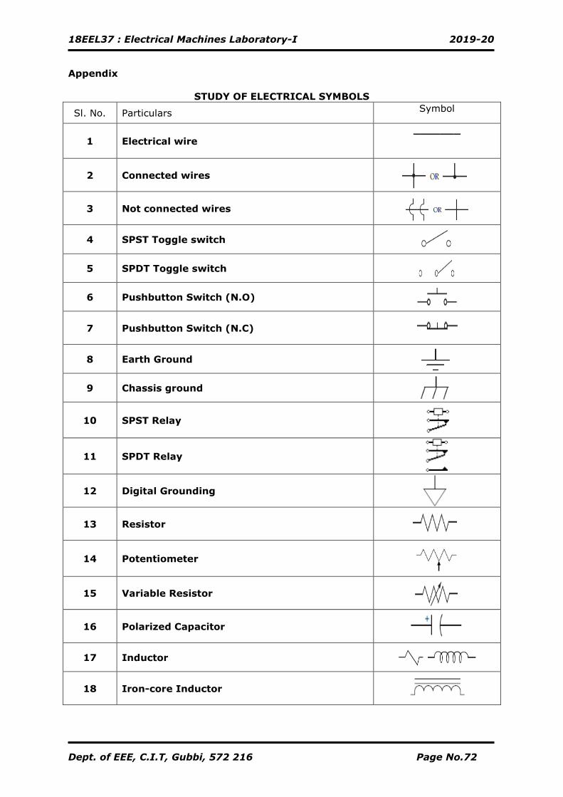
Appendix
STUDY OF ELECTRICAL SYMBOLS
Sl. No. Particulars Symbol
1
Electrical wire
_______
2 Connected wires
3 Not connected wires
4 SPST Toggle switch
5 SPDT Toggle switch
6 Pushbutton Switch (N.O)
7 Pushbutton Switch (N.C)
8 Earth Ground
9 Chassis ground
10 SPST Relay
11 SPDT Relay
12 Digital Grounding
13 Resistor
14 Potentiometer
15 Variable Resistor
16 Polarized Capacitor
17 Inductor
18 Iron-core Inductor
18EEL37 : Electrical Machines Laboratory-I 2019-20
Dept. of EEE, C.I.T, Gubbi, 572 216 Page No.73
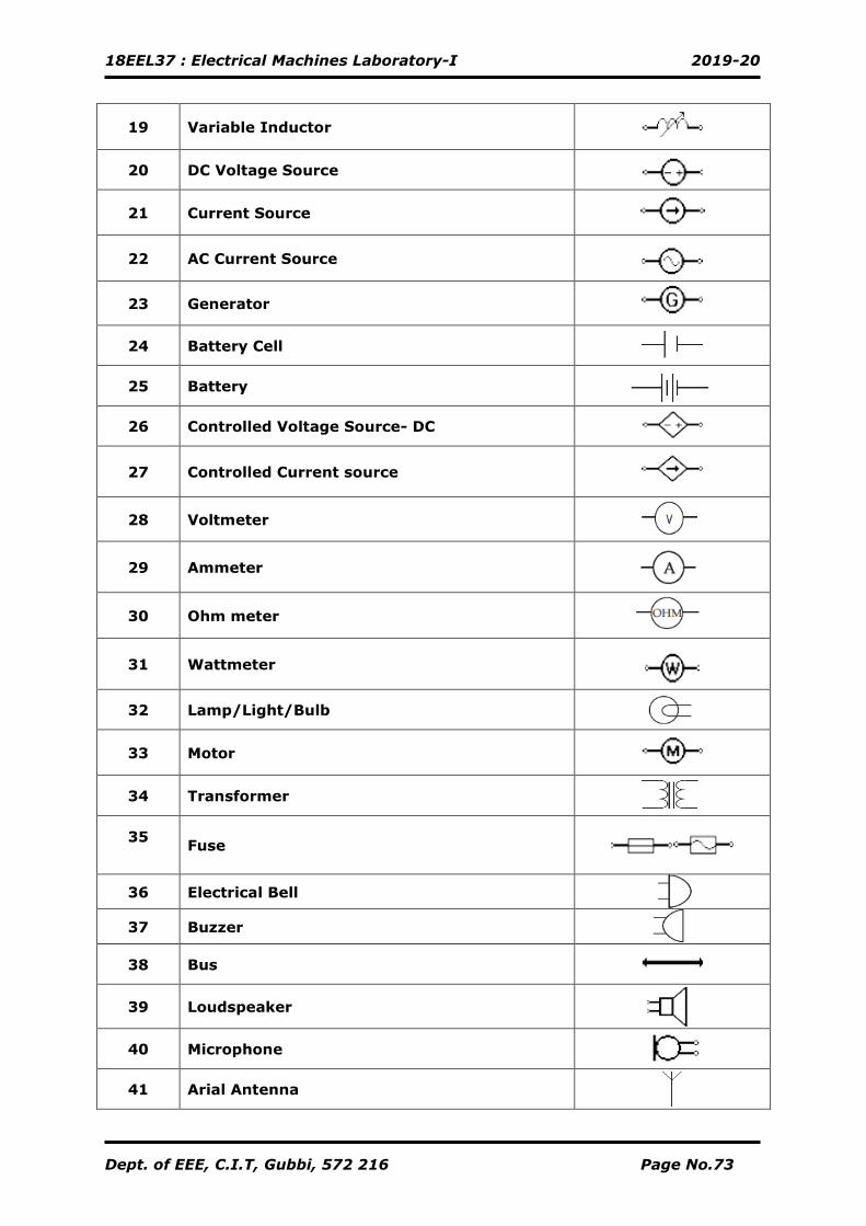
19 Variable Inductor
20 DC Voltage Source
21 Current Source
22 AC Current Source
23 Generator
24 Battery Cell
25 Battery
26 Controlled Voltage Source- DC
27 Controlled Current source
28 Voltmeter
29 Ammeter
30 Ohm meter
31 Wattmeter
32 Lamp/Light/Bulb
33 Motor
34 Transformer
35
Fuse
36 Electrical Bell
37 Buzzer
38 Bus
39 Loudspeaker
40 Microphone
41 Arial Antenna
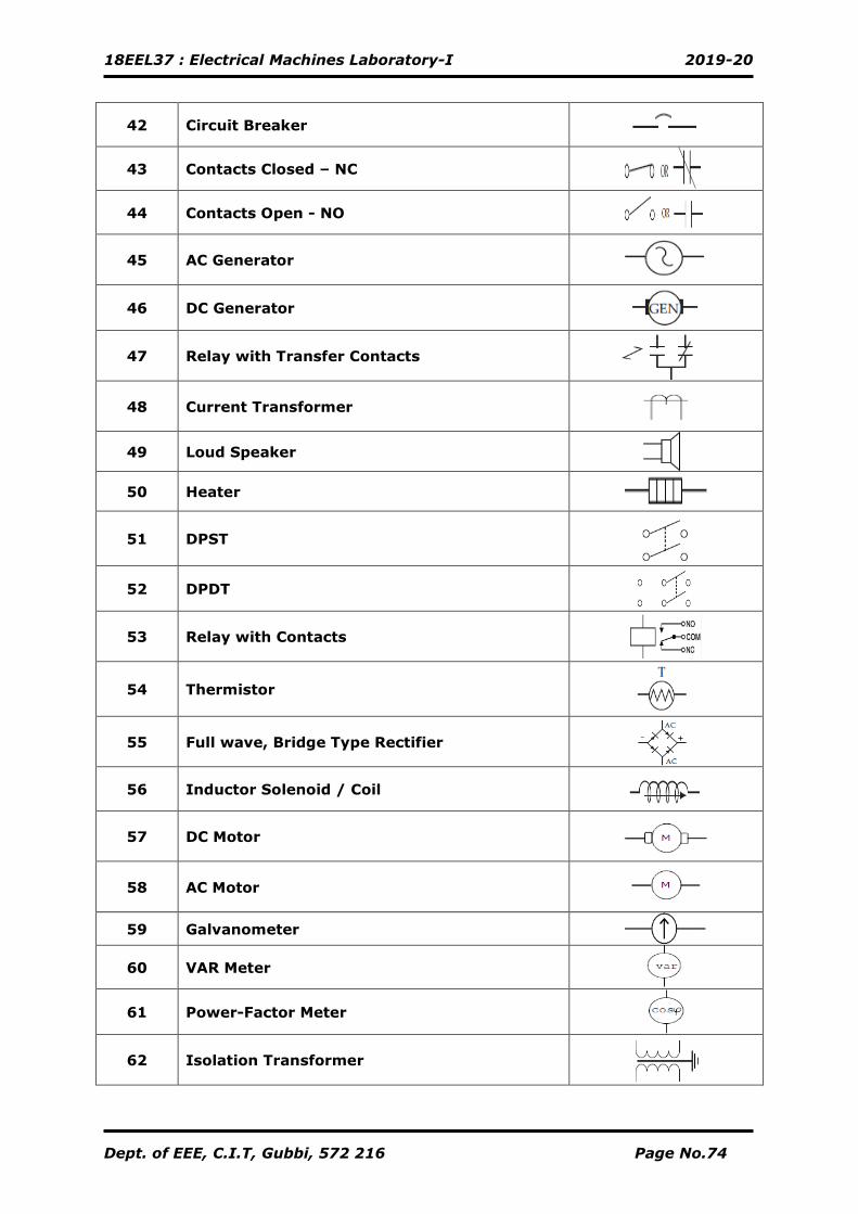
18EEL37 : Electrical Machines Laboratory-I 2019-20
Dept. of EEE, C.I.T, Gubbi, 572 216 Page No.74
42 Circuit Breaker
43 Contacts Closed – NC
44 Contacts Open - NO
45 AC Generator
46 DC Generator
47 Relay with Transfer Contacts
48 Current Transformer
49 Loud Speaker
50 Heater
51 DPST
52 DPDT
53 Relay with Contacts
54 Thermistor
55 Full wave, Bridge Type Rectifier
56 Inductor Solenoid / Coil
57 DC Motor
58 AC Motor
59 Galvanometer
60 VAR Meter
61 Power-Factor Meter
62 Isolation Transformer
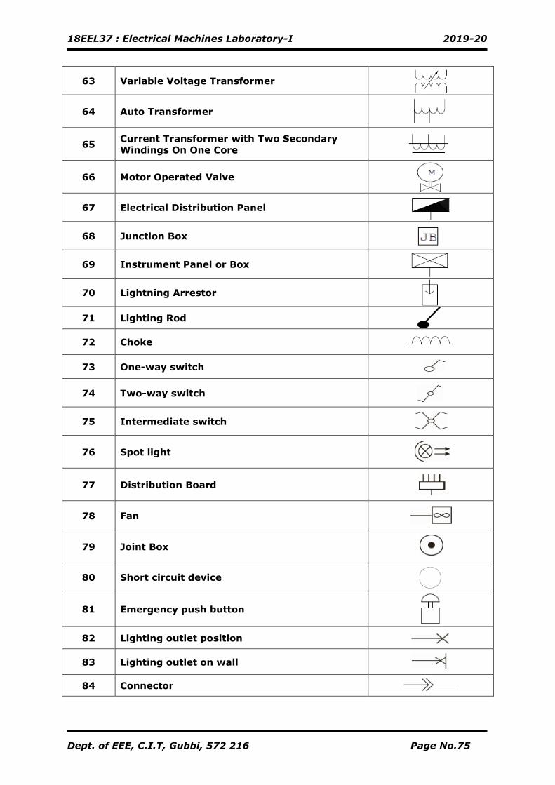
18EEL37 : Electrical Machines Laboratory-I 2019-20
Dept. of EEE, C.I.T, Gubbi, 572 216 Page No.75
63 Variable Voltage Transformer
64 Auto Transformer
65 Current Transformer with Two Secondary
Windings On One Core
66 Motor Operated Valve
67 Electrical Distribution Panel
68 Junction Box
69 Instrument Panel or Box
70 Lightning Arrestor
71 Lighting Rod
72 Choke
73 One-way switch
74 Two-way switch
75 Intermediate switch
76 Spot light
77 Distribution Board
78 Fan
79 Joint Box
80 Short circuit device
81 Emergency push button
82 Lighting outlet position
83 Lighting outlet on wall
84 Connector
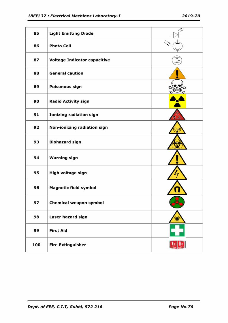
18EEL37 : Electrical Machines Laboratory-I 2019-20
Dept. of EEE, C.I.T, Gubbi, 572 216 Page No.76
85 Light Emitting Diode
86 Photo Cell
87 Voltage Indicator capacitive
88 General caution
89 Poisonous sign
90 Radio Activity sign
91 Ionizing radiation sign
92 Non-ionizing radiation sign
93 Biohazard sign
94 Warning sign
95 High voltage sign
96 Magnetic field symbol
97 Chemical weapon symbol
98 Laser hazard sign
99 First Aid
100 Fire Extinguisher