Embed Size (px)
Citation preview

SREE VIDYANIKETHAN ENGINEERING COLLEGE
(An autonomous institution affiliated to JNTUA, Anantapuramu)
SreeSainath Nagar, Tirupati – 517 102.
DEPARTMENT OF ELECTRICAL AND ELECTRONICS ENGINEERING
Lab Manual
TRANSFORMERS AND INDUCTION
MACHINES LAB (16BT40232)
(II B. Tech., II-Semester, EEE)
Prepared by Mr. A. Muni Sankar
Ms. N S Madhuri Assistant Professor Department of EEE

(An autonomous institution affiliated to JNTUA, Anantapuramu)
Sree Sainath Nagar, Tirupati – 517 102.
DEPARTMENT OF ELECTRICAL AND ELECTRONICS ENGINEERING
Lab Manual
TRANSFORMERS AND INDUCTION
MACHINES LAB (16BT40232)
(II B. Tech., II-Semester, EEE)

ii
16BT40232: TRANSFORMERS AND INDUCTION MACHINES LAB
CONTENTS
S.No. Title Page No.
Vision & Mission
iii
PEOs, POs and PSOs v
Syllabus vii
CO-PO & PSO Mapping ix
Rubrics x
CO Assessment xii
Day - to - Day Evaluation xiii
List of Equipment needed xiv
General Instructions xv
Safety Precautions xvi
Lab Layout xvii
EXP-1 Construction of transformers 1-8
EXP-2 Construction of three phase induction motors 9-14
EXP-3 OC and SC tests on single phase transformer 15-20
EXP-4 Separation of core losses of a single phase transformer 21-23
EXP-5 Load test on single phase transformer 24-26
EXP-6 Sumpner's test on a pair of single phase transformers 27-30
EXP-7 Parallel operation of single phase transformers 31-33
EXP-8 Scott connection of transformers 34-36
EXP-9 Brake test on three phase induction motor 37-39
EXP-10 Separation of no-load losses of three phase induction motor 40-43
EXP-11 No-load and blocked rotor tests on three phase induction motor 44-48
*****
iii
(Autonomous)
Sree Sainath Nagar, Tirupathi – 517 102
Department of Electrical and Electronics Engineering
Vision
To be one of the Nation’s premier Engineering Colleges by achieving the highest order of
excellence in Teaching and Research.
Mission
Through multidimensional excellence, we value intellectual curiosity, pursuit of
knowledge building and dissemination, academic freedom and integrity to enable the
students to realize their potential. We promote technical mastery of Progressive
Technologies, understanding their ramifications in the future society and nurture the next
generation of skilled professionals to compete in an increasingly complex world, which
requires practical and critical understanding of all aspects.

iv
(Autonomous)
Sree Sainath Nagar, Tirupathi – 517 102
Department of Electrical and Electronics Engineering
Vision
To become the Nation's premiere centre of excellence in electrical engineering through
teaching, training, research and innovation to create competent engineering professionals
with values and ethics.
Mission
Department of Electrical Engineering strives to create human resources in Electrical
Engineering to contribute to the nation development and improve the quality of life.
Imparting Knowledge through implementing modern curriculum, academic flexibility
and learner centric teaching methods in Electrical Engineering.
Inspiring students for aptitude to research and innovation by exposing them to
industry and societal needs to creating solutions for contemporary problems.
Honing technical and soft skills for enhanced learning outcomes and employability of
students with diverse background through comprehensive training methodologies.
Inculcate values and ethics among students for a holistic engineering professional
practice.

v
(Autonomous)
Sree Sainath Nagar, Tirupathi – 517 102
Department of Electrical and Electronics Engineering
B.Tech. (Electrical and Electronics Engineering)
Program Educational Objectives:
Within few years of graduation, graduates will
PEO1. Have enrolled in academic program in the disciplines of electrical engineering
and multidisciplinary areas.
PEO2. Become entrepreneurs or be employed as productive and valued engineers in
reputed industries.
PEO3. Engage in lifelong learning, career enhancement and adopt to changing
professional and societal needs.
Program Outcomes:
On successful completion of the program, engineering graduates will be able to:
PO1. Apply the knowledge of mathematics, science, engineering fundamentals, and
concepts of engineering to the solution of complex engineering problems.
(Engineering knowledge)
PO2. Identify, formulate, review research literature, and analyze complex engineering
problems reaching substantiated conclusions using first principles of
mathematics, natural sciences and engineering sciences. (Problem analysis)
PO3. Design solutions for complex engineering problems and design system
components or processes that meet the specified needs with appropriate
consideration for the public health and safety, and the cultural, societal, and
environmental considerations. (Design/development of solutions)
PO4. Use research-based knowledge and research methods including design of
experiments, analysis and interpretation of data, and synthesis of the information
to provide valid conclusions. (Conduct investigations of complex problems)
PO5. Create, select, and apply appropriate techniques, resources, and modern
engineering and IT tools including prediction and modeling to complex
engineering activities with an understanding of the limitations. (Modern tool
usage)
PO6. Apply reasoning informed by the contextual knowledge to assess societal,
health, safety, legal and cultural issues and the consequent responsibilities
relevant to the professional engineering practice. (The engineer and society)
PO7. Understand the impact of the professional engineering solutions in societal and
environmental contexts, and demonstrate the knowledge of and need for

vi
sustainable development. (Environment and sustainability)
PO8. Apply ethical principles and commit to professional ethics and responsibilities
and norms of the engineering practice. (Ethics)
PO9. Function effectively as an individual, and as a member or leader in diverse
teams, and in multidisciplinary settings. (Individual and team work)
PO10. Communicate effectively on complex engineering activities with the engineering
community and with society at large, such as, being able to comprehend and
write effective reports and design documentation, make effective presentations,
and give and receive clear instructions. (Communication)
PO11. Demonstrate knowledge and understanding of the engineering and management
principles and apply these to one's own work, as a member and leader in a team,
to manage projects and in multidisciplinary environments. (Project
management and finance)
PO12. Recognize the need for, and have the preparation and ability to engage in
independent and life-long learning in the broadest context of technological
change. (Life-long learning)
Program Specific Outcomes:
On successful completion of the program, engineering graduates will
PSO1. Demonstrate knowledge of Electrical and Electronic circuits, Electrical
Machines, Power Systems, Control Systems, and Power Electronics for solving
problems in electrical and electronics engineering.
PSO2. Analyze, design, test and maintain electrical systems to meet the specific needs
of the Industry and society.
PSO3. Conduct investigations to address complex engineering problems in the areas of
Electrical Machines, Power Systems, Control Systems and Power Electronics.
PSO4. Apply appropriate techniques, resources and modern tools to provide solutions
for problems related to electrical and electronics engineering.

vii
II B.Tech. - II Semester
(16BT40232)TRANSFORMERS AND INDUCTION
L T P C
MACHINES LAB - - 3 2
ASSESSMENT:
DAY-TO-DAY
EVALUATION
INTERNAL
MARKS
EXTERNAL
MARKS TOTAL
30MARKS 50 MARKS 50 MARKS 100 MARKS
PREREQUISITES: Course on DC Machines Lab
COURSE DESCRIPTION: Construction, types, operation and applications of transformers and
induction machines; Performance evaluation of transformers and induction machines.
COURSE OUTCOMES: On successful completion of the course, students will be able to
CO1. demonstrate knowledge on
construction, operation of various types of transformers and induction machines.
starting and speed control of induction machines.
testing of transformers and induction machines.
parallel operation of transformers.
characteristics of transformers and induction machines.
CO2. analyze the performance of transformers and induction motors for various operating
conditions.
CO3. design the circuit with suitable accessories / controllers for desired operation of
Transformers and Induction motors.
CO4. interpret and synthesize the data obtained from experimentation on transformers &
induction machines and provide valid conclusions.
CO5. select and apply appropriate technique for testing and control of transformers & induction
machines used in domestic and industrial applications.
CO6. apply the conceptual knowledge of Transformers and Induction motors in relevance to
industry and society.
CO7. commit to ethical principles and standards while exercising the practical investigations on
Transformers and Induction motors.
CO8. work individually or in a group while exercising practical investigations in the field of
Transformers and Induction motors.
CO9. communicate effectively in verbal and written form in relevance to Transformers and
Induction motors.
DETAILED SYLLABUS:
PART-A:
1. Construction of transformers
2. Construction of three phase induction motors.
PART-B: Any EIGHT experiments are to be conducted from the following
1. OC and SC tests on single phase transformer.

viii
2. Separation of core losses of a single phase transformer.
3. Load test on single phase transformer.
4. Sumpner's test on a pair of single phase transformers.
5. Parallel operation of single phase transformers.
6. Scott connection of transformers.
7. Brake test on three phase induction motor.
8. Separation of no-load losses of three phase induction motor.
9. No-load and blocked rotor tests on three phase induction motor.
***

ix
CO – PO MAPPING II B. Tech. – II Semester
(16BT40232)TRANSFORMERS AND INDUCTION MACHINES LAB (EEE)
Int. Marks Ext. Marks Total Marks L T P C
50 50 100 -- -- 3 2
Course
Outcomes
Program Outcomes Program Specific
Outcomes
PO1 PO2 PO3 PO4 PO5 PO6 PO7 PO8 PO9 PO10 PO11 PO12 PSO1 PSO2 PSO3 PSO4
CO1 H H
CO2 M H M H
CO3 L M H H
CO4 L M H M
CO5 L M H H M
CO6 L M H L M H
CO7 M H M
CO8 M H L
CO9 L H

x
(Autonomous)
SreeSainath Nagar, Tirupati – 517 102
Department of Electrical and Electronics Engineering
RUBRICS FOR TRANSFORMERS AND MACHINES LAB (16BT40232)
Course Outcome Poor
(0 - 1) Mark
Average
(2 - 3) Marks
Excellent
(4) Marks On successful completion of the course,
students will be able to
CO1
Demonstrate knowledge on
construction, operation
of various types of
transformers and
induction machines.
starting and speed
control of induction
machines.
testing of transformers
and induction machines.
parallel operation of
transformers.
characteristics of
transformers and
induction machines.
Unable to
demonstrate
knowledge on
transformers and
induction machines
for various operating
conditions.
Able to demonstrate
knowledge on
transformers and
induction machine for
various operating
conditions up to some
extent.
Able to demonstrate
knowledge
transformers and
induction machine
for various operating
conditions.
CO2
Analyze the performance of
synchronous and fractional kW
machines for various operating
conditions.
Unable to analyse the
performance of
transformers and
induction machine
Able to analyse the
performance of
transformers and
induction machines
up to some extent.
Able to analyse the
performance of
transformers and
induction machines
CO3
Design the circuit with suitable
accessories / controllers for
desired operating conditions of
synchronous and fractional kW
machines.
Unable to design the
experimental circuit.
Able to design some
parameters of the
circuit.
Able to design the
experimental circuit
based on loading and
rating of
transformers and
induction machines
Poor (0) Average (1-2) Excellent (3)
CO4
Interpret and synthesize the data
obtained from experimentation
on synchronous and fractional
kW machines to provide valid
conclusions.
Unable to interpret
and synthesize the
data obtained from
experimentation on
transformers and
induction machines
Able to interpret and
synthesize the data
obtained from
experimentation on
transformers and
induction machines to
some extent.
Able to interpret and
synthesize the data
obtained from
experimentation on
transformers and
induction machines
CO5 Select and apply appropriate
technique for testing and control
of synchronous and fractional
Unable to select and
apply appropriate
technique for testing
Able to select and
apply appropriate
technique for testing
Able to select and
apply appropriate
technique for testing

xi
kW machines for domestic and
industrial applications.
and control of
transformers and
induction machines.
and control of
transformers and
induction machines to
some extent.
and control of
transformers and
induction machines.
Poor (0) Average (1-2) Excellent (3)
CO6
Apply the conceptual knowledge
of synchronous and fractional
kW machines in relevance to
domestic and industrial needs.
Unable to apply the
conceptual
knowledge of
transformers and
induction machines
in relevance to
industry and society.
Able to apply the
conceptual
knowledge of
transformers and
induction machines in
relevance to industry
and societyto some
extent.
Able to apply the
conceptual
knowledge of
transformers and
induction machines
in relevance to
industry and society.
CO7
Follow ethical principles and
standards while exercising the
practical investigations on
synchronous and fractional kW
machines
Unable to follow
ethical principles and
standards.
Able to follow ethical
principles and
standards to some
extent.
Able to follow
ethical principles and
standards.
CO8
Work individually or in a group
while exercising practical
investigations in the field of
synchronous and fractional kW
machines.
Unable to work
individually or in a
group
Occasionally work
individually or in a
group
Able to work and
execute the problem
individually as well
as in a group.
CO9
Communicate effectively in
verbal and written form in
relevance to synchronous and
fractional kW machines.
Unable to
communicate
effectively in verbal
and written form in
relevance to
transformers and
induction machines.
Able to communicate
effectively in verbal
and written form in
relevance to
transformers and
induction machines to
some extent.
Able to communicate
effectively in verbal
and written form in
relevance to
transformers and
induction machines
Faculty In-charge
Chairman, BoS&
HOD, EEE

xii
II B. Tech., II-Semester, EEE
L T P C 16BT40232: TRANSFORMERS AND INDUCTION MACHINES LAB - - 3 2
CO ASSESMENT
DAY-TO-DAY EVALUATION: (30 Marks)
CO Assessment Parameter Total
Marks: 30
CO1 Identify various of parts of transformers and AC machines 4M
CO2 Analyze the performance of transformers and AC machines 4M
CO3 Design the circuit based on loading and rating of the AC machine. 4M
CO4 Demonstrate skills in
Obtaining the various characteristics of transformers and AC
machines.
Determining the performance characteristics of transformers and
AC machines.
Determining and separation of losses in transformers and AC
machines.
4M
CO5 Function effectively as individual and as member in a team 4M
CO6 Communicate effectively both oral and written 10M
INTERNAL EXAM EVALUATION: (20 Marks)
Each student has to conduct a suitable experiment for the task assigned to him/her individually
similar to end semester external examination. The performance of the student will be evaluated as
follows:
CO Assessment Parameter Total
Marks:
20
CO1 Identify various parts of DC machine and different starters 2M
CO2 Analyze the performance of transformers and AC machines 4M
CO3 Design the circuit based on loading and rating of the AC machine. 4M
CO4 Demonstrate skills in
Obtaining the various characteristics of transformers and AC
machines.
Determining the performance characteristics of transformers and
AC machines.
Determining and separation of losses in transformers and AC
machines.
4M
CO5 Function effectively as individual and as member in a team 2M
CO6 Communicate effectively both oral and written 4M
xiii
(Autonomous)
SreeSainath Nagar, Tirupati – 517 102
Department of Electrical and Electronics Engineering
Year & Semester II B.Tech. II Semester Roll No :
Name of the Laboratory Transformers and Induction Machines Lab Course Code 16BT50232
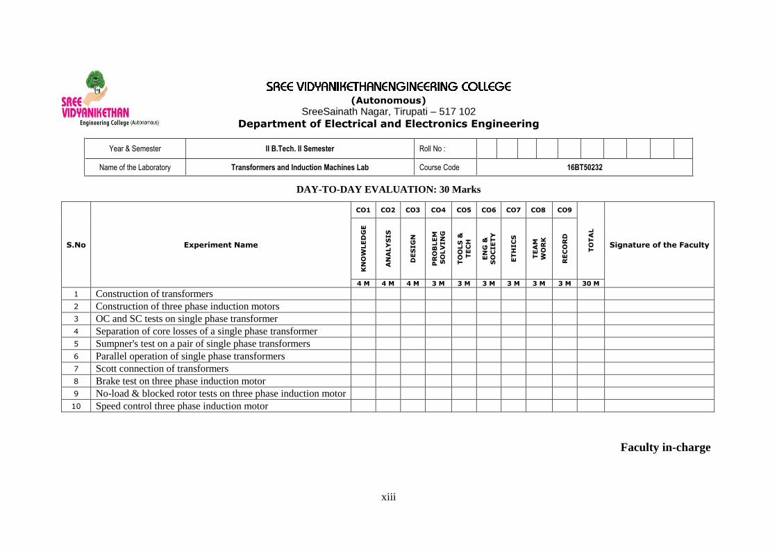
DAY-TO-DAY EVALUATION: 30 Marks
S.No Experiment Name
CO1 CO2 CO3 CO4 CO5 CO6 CO7 CO8 CO9
TO
TA
L
Signature of the Faculty
KN
OW
LE
DG
E
AN
ALY
SIS
DE
SIG
N
PR
OB
LE
M
SO
LV
IN
G
TO
OLS
&
TE
CH
EN
G &
SO
CIE
TY
ET
HIC
S
TE
AM
WO
RK
RE
CO
RD
4 M 4 M 4 M 3 M 3 M 3 M 3 M 3 M 3 M 30 M
1 Construction of transformers
2 Construction of three phase induction motors
3 OC and SC tests on single phase transformer
4 Separation of core losses of a single phase transformer
5 Sumpner's test on a pair of single phase transformers
6 Parallel operation of single phase transformers
7 Scott connection of transformers
8 Brake test on three phase induction motor
9 No-load & blocked rotor tests on three phase induction motor
10 Speed control three phase induction motor
Faculty in-charge

xiv
(Autonomous)
Sree Sainath Nagar, Tirupati – 517 102.
Department of EEE
II B. Tech., II-Semester, EEE
16BT40232: TRANSFORMERS AND INDUCTION
MACHINES LAB
List of Equipment Needed
S.No Name of the Equipment Rating
1. Transformer
1-Ø, 2 KVA, 120 V/230 V.
1-Ø, 3 KVA, (0-50-86.6-100)% TAPPINGS,
230V/415V.
2. Induction motor 7.5 HP, 3-Ø, 415V.
0.5 HP, 1-Ø, 240V.
3. M-G Set DC Shunt Motor -7.5 HP, 220 V,
Alternator -5 KVA, 3-Ø, 415V.
4. 1-ø variac 230 V/(0-270) V.
5. 3-ø variac 415 V/(0-470) V.
6. Rectifier (0-220) V, 100 A.
7. Resistive load or lamp
load 7 KW, 230V.
8. Panel board --

xv
(Autonomous)
Sree Sainath Nagar, Tirupati – 517102
Department of Electrical and Electronics Engineering
GENERAL INSTRUCTIONS
1. Shirts should be tucked in.
2. Perform only appropriate experiments and be sure that you understand the
procedures involved before you begin.
3. Girl students should wear apron.
4. Supply to test table should be obtained only through the lab technician.
5. Energize the circuit only after getting approval from the faculty-in-charge.
6. Students who are not appropriately attired will not be allowed to perform
experiments.
7. No horse-play before, during or after the lab.
8. Be familiar with emergency procedures & know the location of emergency
equipment. First aid kit for minor injuries is with the lab technician.
9. Do not modify equipment settings unless instructed by lab handout or lab
instructor.
10. Unauthorized experiments and working in the laboratory outside the class hours
without permission are strictly prohibited.
11. Keep bags in designated areas.
12. If you feel unwell or dizzy while doing the experiment, stop immediately, sit
down and notify the instructor.
xvi
(Autonomous)
Sree Sainath Nagar, Tirupati – 517102
Department of Electrical and Electronics Engineering
SAFETY PRECAUTIONS
1. Wearing shoes is compulsory.
2. Do not use extension cords for permanent wiring.
3. Electrical cords on equipment must be in good condition.
4. Cables used must be appropriate to their loading. Avoid contact with water.
5. Do not tamper with or touch any equipment not specifically related to the current
experiment.
6. Do not allow chains / ornaments to hang.
7. Do not lean over rotating machinery.
8. Do not operate any other machine not related to your experiment.
9. Follow precautions where ever necessary as indicated in the lab manual.
10. Do not touch any live part in the circuit while Experiment is ON.

xvii
1 Induction Motor – DC Compound Motor – Smooth Cylindrical Alternator 2 Induction Motor – DC Compound Motor – Smooth Cylindrical Alternator 3 Induction Motor – DC Compound Motor – Smooth Cylindrical Alternator 4 Slip Ring Induction Motor – DC Compound Motor – Salient Pole Alternator 5 Slip Ring Induction Motor – DC Compound Motor – Salient Pole Alternator 6 Slip Ring Induction Motor – DC Compound Motor – Salient Pole Alternator 7 Universal Motor 8 Single Phase Induction Motor 9 Meter Stack
Total cost of the equipment : Rs. 32,58,302.92/-
Area of the Laboratory : 95.13 Sq.mts
Name of the Lab in-charge : Mr. A. Muni Sankar
Name of the Technician : Mr. Sk. Azeez
Student Table
ENTRANCE
Stu
de
nt
Ta
ble
Work Table - 1
Work Table - 2
Work Table - 3
Work Table - 4
Work Table - 5
Work Table - 6
Faculty
Table
Work Table -7 Work Table - 8
AC Machines Lab Layout3
2 fe
et
32 feet
9
Te
ch
nic
ian
Ta
ble

1
1. CONSTRUCTION OF TRANSFORMERS
AIM:
To study about the constructional details of transformers.
Construction:
Basically a transformer consists of two inductive windings and a laminated steel core.
The coils are insulated from each other as well as from the steel core.
Fig 1.1: Detailed construction of transformer
A transformer may also consist of a container for winding and core assembly (called as
tank), suitable bushings to take over the terminals, oil conservator to provide oil in the
transformer tank for cooling purposes etc. The figure at left illustrates the basic construction of a
transformer.

2
Transformer laminated steel sheet shapes in all types of transformers, core is constructed
by assembling (stacking) laminated sheets of steel, with minimum air-gap between them (to
achieve continuous magnetic path).
The steel used is having high silicon content and sometimes heat treated, to provide high
permeability and low hysteresis loss. Laminated sheets of steel are used to reduce eddy current
loss. The sheets are cut in the shape as E, I and L.
Fig 1.2 Different types of laminations
To avoid high reluctance at joints, laminations are stacked by alternating the sides of
joint. That is, if joints of first sheet assembly are at front face, the joints of following assemble are
kept at back face.
CORE
The core acts as support to the winding in the transformer. It also provides a low
reluctance path to the flow of magnetic flux. It is made of laminated soft iron core in order to
reduce eddy current loss and Hysteresis loss. The composition of a transformer core depends on
such as factors voltage, current, and frequency.
The diameter of the transformer core is directly proportional to copper loss and is
inversely proportional to iron loss. If the diameter of the core is decreased, the weight of the steel
in the core is reduced, which leads to less core loss of the transformer and the copper loss
increase. When the diameter of the core is increased, the vise-versa occurs.

3
Fig 1.3: Main parts of transformer
WINDING
Two sets of winding are made over the transformer core and are insulated from each
other. Winding consists of several turns of copper conductors bundled together, and connected in
series. Winding can be classified in two different ways:
1) Based on the input and output supply
2) Based on the voltage range
Within the input/output supply classification, winding are further categorized:
Primary winding - These are the winding to which the input voltage is applied.
Secondary winding - These are the winding to which the output voltage is applied.
Within the voltage range classification, winding are further categorized:
High voltage winding - It is made of copper conductor. The number of turns made shall
be the multiple of the number of turns in the low voltage winding. The conductor used
will be thinner than that of the low voltage winding.
Low voltage winding - It consists of fewer number of turns than the high voltage
winding. It is made of thick copper conductors. This is because the current in the low
voltage winding is higher than that of high voltage winding.
Input supply to the transformers can be applied from either low voltage (LV) or high voltage
(HV) winding based on the requirement.

4
CONSERVATOR
The conservator conserves the transformer oil. It is an airtight, metallic, cylindrical drum
that is fitted above the transformer. The conservator tank is vented to the atmosphere at the top,
and the normal oil level is approximately in the middle of the conservator to allow the oil to
expand and contract as the temperature varies. The conservator is connected to the main tank
inside the transformer, which is completely filled with transformer oil through a pipeline.
BREATHER
The breather controls the moisture level in the transformer. Moisture can arise when
temperature variations cause expansion and contraction of the insulating oil, which then causes
the pressure to change inside the conservator. Pressure changes are balanced by a flow of
atmospheric air in and out of the conservator, which is how moisture can enter the system. If the
insulating oil encounters moisture, it can affect the paper insulation or may even lead to internal
faults. Therefore, it is necessary that the air entering the tank is moisture-free.
The transformer's breather is a cylindrical container that is filled with silica gel. When the
atmospheric air passes through the silica gel of the breather, the air's moisture is absorbed by the
silica crystals. The breather acts like an air filter for the transformer and controls the moisture
level inside a transformer. It is connected to the end of breather pipe.
Fig 1.4: Conservator arrangement

5
TAP CHANGER
The output voltage of transformer varies according to its input voltage and the load.
During loaded conditions, the voltage on the output terminal decreases, whereas during off-load
conditions the output voltage increases. In order to balance the voltage variations, tap changers
are used. Tap changers can be either on-load tap changers or off-load tap changers. In an on-load
tap changer, the tapping can be changed without isolating the transformer from the supply. In an
off-load tap changer, it is done after disconnecting the transformer. Automatic tap changers are
also available.
Fig 1.5: Schematic arrangement of tap changer
COOLING TUBES
Cooling tubes are used to cool the transformer oil. The transformer oil is circulated
through the cooling tubes. The circulation of the oil may either be natural or forced. In natural
circulation, when the temperature of the oil raises the hot oil naturally rises to the top and the cold
oil sinks downward. Thus the oil naturally circulates through the tubes. In forced circulation, an
external pump is used to circulate the oil.

6
Fig 1.6 Schematic diagram of Buchholz relay
BUCHHOLZ RELAY
The Buchholz Relay is a protective device container housed over the connecting pipe
from the main tank to the conservator tank. It is used to sense the faults occurring inside the
transformer.
It is a simple relay that is operated by the gases emitted during the decomposition of
transformer oil during internal faults. It helps in sensing and protecting the transformer from
internal faults.
EXPLOSION VENT
The explosion vent is used to expel boiling oil in the transformer during heavy internal
faults in order to avoid the explosion of the transformer. During heavy faults, the oil rushes out of
the vent. The level of the explosion vent is normally maintained above the level of the
conservatory tank.

7
Fig 1.7: Types of cross sections of core in a transformer
TYPES OF TRANSFORMERS:
Transformers can be classified on different basis, like types of construction, types of
cooling etc.
(A) On the basis of construction, transformers can be classified into two types as;
Core type transformer and
Shell type transformer, which are described below.
Core type and shell type transformer:
Core Type Transformer: In core type transformer, windings are cylindrical former
wound, mounted on the core limbs as shown in the fig1.7 above. The cylindrical coils
have different layers and each layer is insulated from each other. Materials like paper,
cloth or mica can be used for insulation. Low voltage windings are placed nearer to the
core, as they are easier to insulate.
Shell Type Transformer: The coils are former wound and mounted in layers stacked with
insulation between them. A shell type transformer may have simple rectangular form (as
shown in above fig 1.7), or it may have a distributed form.
(B) On the basis of their purpose
Step up transformer: Voltage increases (with subsequent decrease in current) at
secondary.
Step down transformer: Voltage decreases (with subsequent increase in current) at
secondary.
(C) On the basis of type of supply
Single phase transformer

8
Three phase transformer
(D) On the basis of their use
Power transformer: Used in transmission network and high rated transformer.
Distribution transformer: Used in distribution network, comparatively lower rating than
that of power transformers.
Instrument transformer: Used in relay and protection purpose in different instruments in
industries.
o Current transformer (CT)
o Potential transformer (PT)
(E) On the basis of cooling employed
Oil-filled self-cooled type
Oil-filled water cooled type
Air blast type (air cooled)
RESULT:
9
2. CONSTRUCTION OF 3-PHASE INDUCTION MOTOR
AIM:
To study about the constructional details of 3-phase induction motor.
CONSTRUCTION:
The three phase induction motor is the most widely used electrical motor. Almost 80% of
the mechanical power used by industries is provided by three phase induction motors because
of its simple and rugged construction, low cost, good operating characteristics, the absence of
commutator and good speed regulation. In three phase induction motor, the power is transferred
from stator to rotor winding through induction. The induction motor is also called a synchronous
motor as it runs at a speed other than the synchronous speed.
Like any other electrical motor induction motor also have two main parts namely
rotor and stator.
1. Stator: As its name indicates stator is a stationary part of induction motor. A stator winding
is placed in the stator of induction motor and the three phase supply is given to it.
2. Rotor: The rotor is a rotating part of induction motor. The rotor is connected to the
mechanical load through the shaft.
Depending upon the type of rotor construction used the three phase induction motor are
classified as:
Squirrel cage induction motor,
Slip ring induction motor or wound induction motor or phase wound induction motor.
The other parts, which are required to complete the induction motor, are:
1. Shaft for transmitting the torque to the load. This shaft is made up of steel.
2. Bearings for supporting the rotating shaft.
3. One of the problems with electrical motor is the production of heat during its rotation. To
overcome this problem, we need a fan for cooling.
4. For receiving external electrical connection Terminal box is needed.
5. There is a small distance between rotor and stator which usually varies from 0.4 mm to 4
mm. Such a distance is called air gap.
Stator of Three Phase Induction Motor:
The stator of the three-phase induction motor consists of three main parts:
1. Stator frame,
2. Stator core,
3. Stator winding or field winding.

10
Stator Frame:
It is the outer part of the three phase induction motor. Its main function is to support the
stator core and the field winding. It acts as a covering, and it provides protection and mechanical
strength to all the inner parts of the induction motor.
Fig 2.1: stator frame
The frame is either made up of die-cast or fabricated steel. The frame of three phase
induction motor should be strong and rigid as the air gap length of three phase induction motor is
very small. Otherwise, the rotor will not remain concentric with the stator, which will give rise to
an unbalanced magnetic pull.
Stator Core:
The main function of the stator core is to carry the alternating flux. In order to reduce the
eddy current loss, the stator core is laminated.
Fig 2.2: stator core and laminations
11
These laminated types of structure are made up of stamping which is about 0.4 to 0.5 mm
thick. All the stamping are stamped together to form stator core, which is then housed in stator
frame. The stamping is made up of silicon steel, which helps to reduce the hysteresis loss
occurring in the motor.
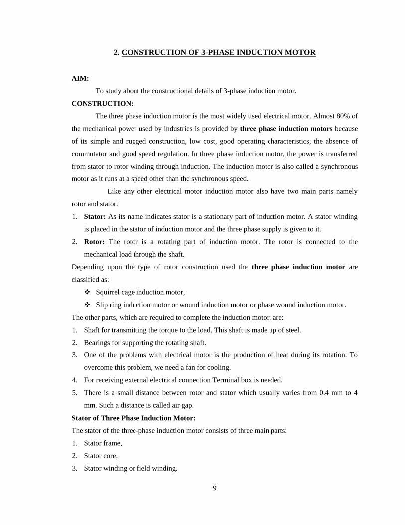
Stator Winding or Field Winding
The slots on the periphery of the stator core of the three-phase induction motor carry
three phase windings. We apply three phase ac supply to this three-phase winding. The three
phases of the winding are connected either in star or delta depending upon which type of starting
method we use. We start the squirrel cage motor mostly with star-delta stater and hence the stator
of squirrel cage motor is delta connected.
Fig 2.3: stator winding
We start the slip ring three-phase induction motor by inserting resistances so; the stator
winding of slip ring induction motor can be connected either in star or delta. The winding wound
on the stator of three phase induction motor is also called field winding, and when this winding is
excited by three phase ac supply, it produces a rotating magnetic field.
Types of Three Phase Induction Motor
1. Squirrel Cage Three Phase Induction Motor
The rotor of the squirrel cage three phase induction motor is cylindrical and have slots on
its periphery. The slots are not made parallel to each other but are bit skewed as the skewing
prevents magnetic locking of stator and rotor teeth and makes the working of the motor more
smooth and quieter.

12
The squirrel cage rotor consists of aluminum, brass or copper bars (copper bras rotor is
shown in the figure beside). These aluminum, brass or copper bars are called rotor conductors and
are placed in the slots on the periphery of the rotor.
The rotor conductors are permanently shorted by the copper, or aluminum rings called the
end rings. To provide mechanical strength, these rotor conductors are braced to the end ring and
hence form a complete closed circuit resembling like a cage and hence got its name as squirrel
cage induction motor.
The squirrel cage rotor winding is made symmetrical. As end rings permanently short the
bars, the rotor resistance is quite small, and it is not possible to add external resistance as the bars
get permanently shorted. The absence of slip ring and brushes make the construction of Squirrel
cage three-phase induction motor very simple and robust and hence widely used three phase
induction motor.
These motors have the advantage of adopting any number of pole pairs. The below
diagram shows a squirrel cage induction rotor having aluminum bars short circuit by aluminum
end rings.
Fig 2.4: squirrel cage induction motor
Advantages of Squirrel Cage Induction Rotor
1. Its construction is very simple and rugged.
2. As there are no brushes and slip ring, these motors requires less maintenance.

13
Applications of Squirrel Cage Induction Rotor
We use the squirrel cage induction motors in: lathes,
drilling machine,
fan,
blowers
printing machines, etc
2. Slip Ring or Wound Rotor Three Phase Induction Motor
In this type of three phase induction motor the rotor is wound for the same
number of poles as that of the stator, but it has less number of slots and has fewer turns per phase
of a heavier conductor. The rotor also carries star or delta winding similar to that of the stator
winding. The rotor consists of numbers of slots and rotor winding are placed inside these slots.
The three end terminals are connected together to form a star connection. As its name indicates,
three phase slip ring induction motor consists of slip rings connected on the same shaft as that of
the rotor. The three ends of three-phase windings are permanently connected to these slip rings.
Fig 2.5: Slip ring induction motor
The external resistance can be easily connected through the brushes and slip rings and
hence used for speed controlling and improving the starting torque of three phase induction

14
motor. The brushes are used to carry current to and from the rotor winding. These brushes are
further connected to three phase star connected resistances.
At starting, the resistance is connected to the rotor circuit and is gradually cut out as the
rotor pick up its speed. When the motor is running the slip rings are shorted by connecting a
metal collar, which connects all slip ring together, and the brushes are also removed. This reduces
the wear and tear of the brushes. Due to the presence of slip rings and brushes the rotor
construction becomes somewhat complicated therefore it is less used as compare to squirrel cage
induction motor.
Fig 2.6: Schematic diagram of slip ring induction motor
Advantages of Slip Ring Induction Motor
1. It has high starting torque and low starting current.
2. Possibility of adding additional resistance to control speed.
Application of Slip Ring Induction Motor
Slip ring induction motors are used where high starting torque is required i.e., in:
hoists,
cranes,
elevator etc.
RESULT:

15
3. OC & SC TESTS ON SINGLE PHASE TRANSFORMER
AIM:
(a) To predetermine the efficiency and regulation of single phase transformer by conducting
no-load test (or) open circuit test and short circuit test.
(b) To draw the equivalent circuit of single phase transformer referred to LV side as well as
HV side.
APPARATUS REQUIRED:
S.No. Apparatus Type Range Quantity
CIRCUIT DIAGRAM:
Open Circuit Test:
Fig 3.1: Circuit for open circuit test
Name Plate Details:
KVA rating :
LV Side Voltage :
HV Side Voltage :
Frequency :
Number of Phases :
Type of Construction :

16
Short Circuit:
Fig 3.2: Circuit diagram for short circuit test
OBSERVATIONS:
OC Test:
Vo1 (V) Io
1 (A) Wo = W x M.F (W)
SC Test:
VSC (V) ISC (A) WSC = W x M.F (W)
Where
M. F. = Multiplication factor = FSD
VI cos
FSD = Full scale divisions
PRECAUTIONS:
1. Avoid loose and wrong connections.
2. All knife switches should be open initially.
3. Single phase variac should be at minimum potential position initially.
4. Readings are taken without parallax error.
PROCEDURE:
For OC Test:
1. Connect the circuit as per fig 3.1.
2. Observe all precautions and close the DPST Switch.
3. Apply the rated voltage by increasing variac output gradually.

17
76.093.02.1 222
01
2
0101 RZX
207.076.0522.0 2
01
2
02 XKX
253.093.0522.0 201
202 RKR
327.02.1522.0 201
202 ZKZ
4. Note down the readings of all the meters.
For SC Test:
1. Connect the circuit as per fig 3.2.
2. Observe all precautions and close the DPST Switch.
3. Apply the rated current by increasing variac output gradually.
4. Note down the readings of all the meters.
MODEL CALCULATIONS:
Let the transformer be the step-down transformer
Primary is H. V. side. Secondary is L. V. side
K = 1
2
V
V Transformation ratio.
OC TEST CALCULATIONS:
cos 0= Wo/(Vo1Io
1)
sin20= (1- cos 0
2)
sin0=
Iwl = I0
l cos 0
Iµl = I0
l sin 0
Rl0=V0
1/Iw
l
X1
0=V01/Iµ
l
R0= Rl0/K
2
X0= Xl0/K
2
I0= I0l*K
IW= Iwl*K
Iµ= Iµl*K
SC TEST CALCULATIONS:
R01=Wsc/I2SC
Z01= VSC/ISC

18
100
sincosRe%
2
022022 xV
XIRIgulation
CALCULATIONS TO FIND EFFICIENCY:
For reading 1:- 10% of full load and at Unity Power factor
Copper losses = Wsc x (10% of Full Load)2
where WSC = full – load cupper losses
Constant losses = W0
Output = 10% of kVA x cos
Input = output + Cu. Loss + constant loss=
% 100xInput
Outputefficiency
CALCULATIONS TO FIND REGULATION:
For reading 1: for full load 0.1 pf lag
‘+’ for lagging power factors
‘-‘ for leading power factors
Efficiency at different loads and P.f’s:
cos 2 = 0.707 Lag cos 1 = Unity pf
S.No.
Load
Cu.
loss
(W)
Output
(W)
Input
(W) %
X
x
S.No Load
Cu.
loss
(W)
Output
(W)
Input
(W) %

19
Regulation at different power factors:
MODEL GRAPHS:
Fig 3.3: Plot of % efficiency Vs output Fig 3.4: Plot of % regulation Vs power factor
EQUIVALENT CIRCUIT:
Fig 3.5: Equivalent circuit referred to LV side
Lagging Pf Leading Pf
S.No. P.F. % Reg. S.No. P. F. % Reg.

20
Fig 3.6: Equivalent circuit referred to HV side
Result:

21
4. SEPARATION OF CORE LOSSES OF A SINGLE PHASE TRANSFORMER
AIM:
To separate the core losses of a given single phase transformer by conducting no-load test
on it at different frequencies provided v/f is constant.
APPARATUS:
S.No. Apparatus Type Range Quantity
CIRCUIT DIAGRAM:
Fig 4.1: Circuit diagram for separation of core losses
NAME PLATE DETAILS:
a) Motor and alternator:
PARAMETER MOTOR ALTERNATOR
Power
Voltage
Current
Type
Speed

22
Excitation Voltage
Excitation Current
b) Transformer:
KVA rating :
LV Side Voltage :
HV Side Voltage :
Frequency :
Number of Phases :
Type :
PRECAUTIONS:
1. Avoid loose connections and wrong connections.
2. All knife switches should be open initially.
3. Readings are to be taken without any parallax error.
4. Initially field rheostat should be in minimum resistance position and armature rheostat should
be in maximum resistance position.
5. Rectifier output should be in minimum voltage position initially.
PROCEDURE:
1. Make the connections as per the fig 4.1.
2. Observe all precautions and close the DPST Switch1.
3. Vary the armature rheostat and then field rheostat (if required) so that motor runs at rated
speed of alternator.
4. Close the DPST Switches 2&3 and vary rectifier output up to voltmeter shows rated voltage.
5. Take down all meter readings.
6. Decrease the motor speed by varying armature rheostat in steps up to 50% of rated speed and
in each step note down all meter readings.
MODEL CALCULATIONS:
N
fP
20
P
fN 1
1
120
frequencyrated
voltagerated
f
V
where, f = rated frequency,
f1 = selected frequency,
N = rated speed,
N1 = speed corresponding to f1
Let Wh = Af ; WC = Bf2
;
Wi = Wh + We = Af + Bf2
Wi/f = A + B x f
A Oa from graph
B Y/x

23
Fig 4.2: Plot of Wi/f Vs frequency
OBSERVATIONS:
S.No. Frequency
(Hz)
Hysteresis Loss
(Watts)
Eddy current
Losses
(Watts)
Total Losses
(Watts)
RESULT:
S. No. Speed in
rpm
Frequency
in Hz
Voltage in
volts E/f
Wi=W X Mf
(Watts)
Wi/f
ratio

24
5. LOAD TEST ON A SINGLE PHASE TRANSFORMER
AIM:
To conduct load test on single phase transformer and to find efficiency and percentage
voltage regulation of it.
APPARATUS REQUIRED:
NAME PLATE DETAILS:
KVA rating :
LV Side Voltage :
HV Side Voltage :
Frequency :
Number of Phases :
Type of Construction :
PRECAUTIONS:
1. Auto Transformer should be in minimum position.
2. The AC supply is given and removed from the transformer under no load condition.
PROCEDURE:
1. Connections are made as per the Fig 5.1.
2. After checking the no load condition, minimum position of auto transformer and DPST
switch is closed.
3. Ammeter, Voltmeter and Wattmeter readings on both primary side and secondary sides
are noted.
4. The load is increased and for each load, Voltmeter, Ammeter and Wattmeter readings on
S.No. Apparatus Range Type Quantity

25
both primary and secondary sides are noted.
5. Again no load condition is obtained and DPST switch is opened.
CIRCUIT DIAGRAM:
Fig 5.1: Circuit diagram for load test
TABULAR COLUMN:
S.No.
Input
Voltage
(v1)
Input
Power W1
x MF
Output
Voltage
(v2)
Output
current
(I2)
Output
Power W2
x MF
%
Efficiency
%
Regulation
FORMULAE:
Output Power = W2 x Multiplication factor
Input Power = W1 x Multiplicationfactor

26
100Re% xagenoloadvolt
eloadvoltagageNoloadvoltgulation
100Re% xagenoloadvolt
eloadvoltagageNoloadvoltgulation
100% XwattsinpowerInput
wattsinpoweroutputefficiency
MODEL CALCULATIONS:
For 3rd
reading:
Output Power = W2 x Multiplication factor
Input Power = W1 x Multiplication factor
100% XwattsinpowerInput
wattsinpoweroutputefficiency
MODEL GRAPH:
Fig 5.2: Efficiency and regulation characteristics
RESULT:

27
6. SUMPNER'S TEST ON A PAIR OF SINGLE PHASE TRANSFORMERS
AIM:
To find out the iron loss, copper loss and the efficiency of each transformer by
conducting Sumpner’s test on two identical single phase transformers.
APPARATUS REQUIRED:
S.No. Apparatus Type Range Quantity
CIRCUIT DIAGRAM:
Fig 6.1: Circuit diagram for sumpner’s test
NAME PLATE DETAILS:
KVA rating :
LV Side Voltage :
HV Side Voltage :
Frequency :
Number of Phases :
Type of Construction :

28
PRECAUTIONS:
1. Avoid loose connections and wrong connections.
2. All knife switches should be open initially.
3. Readings are to be taken without any parallax error.
4. 1-Ø variac must be in minimum output position initially.
PROCEDURE:
1. Connect the circuit as per the fig 6.1.
2. Observe all precautions and close the DPST Switch1.
3. Vary the variac till the rated voltage is present in the primaries of transformer.
4. Note down the Wattmeter (W0) reading, Voltmeter (V0) reading and ammeter (I0)
reading.
5. Close the SPST switch when voltage Vab = 0 (see circuit diagram).
6. Observe all precautions and close the DPST Switch2. Now vary the corresponding Variac
up to rated current of transformers.
7. Note down the Wattmeter (Wsc) reading, Voltmeter (Vsc) reading and ammeter (Isc)
reading.
MODEL CALCULATIONS:
Losses in each transformer = 2
0 scww
% combined = 1000
xwwIV
IV
scscsc
scsc
=
For reading 3:
For Pf=Unity
Load=30 %
ISC= WI= WCu
ISC=17.4Xload=
WCu= WCu/2 X (load)2=
WI= Wi/2=
Output =KVAXCosφX0.3
Input = Output + Losses
Efficiency=Output/Input X 100

29
MODEL GRAPH:
Fig 6.2: Efficiency characteristics at different Power Factors
OBSERVATION:
V0 (V) I0 (A) W0 (W)
Vsc (V) Isc (A) Wsc (W)
For CosΦ =Unity
% of load V0
(V) I0 (A)
Isc
(A)
Wi
(W)
Wcu
(W)
Wi /2
(W)
Wcu /2
(W)
Total
Loss
(W)
Input
(W)
Output
(W) %η

30
For CosΦ =0.707
% of load V0
(V) I0 (A)
Isc
(A)
Wi
(W)
Wcu
(W)
Wi /2
(W)
Wcu /2
(W)
Total
Loss
(W)
Input
(W)
Output
(W) %η
RESULT:

31
7. PARALLEL OPERATION OF TWO SINGLE PHASE TRANSFORMERS
AIM:
To connect two single phase transformers in parallel and to study how they share a
common load.
APPARATUS:
S.No. Apparatus Type Range Quantity
CIRCUIT DIAGRAM:
Fig 7.1: Circuit diagram for parallel operation
NAME PLATE DETAILS:
KVA rating :
LV Side Voltage :
HV Side Voltage :

32
Frequency :
Number of Phases :
Type of Construction :
PRECAUTIONS:
1. Keep all knife switches open initially.
2. Initially load should be off position.
3. Single phase variac should be minimum potential position initially.
4. Take meter readings without parallax error.
PROCEDURE:
1. Make the connections as per the fig 7.1.
2. Observe the precautions and close DPST Switch 1.
3. Vary the variac up to rated lv voltage of transformers. Observe the reading of voltmeter
‘Vab’, If Vab is zero close the SPST switch. Otherwise inter change secondary terminals
of either transformer 1or 2.
4. Close the DPST switch 2 after reading of voltmeter, Vab is zero and note down the
readings of all meters.
5. Vary the load in steps up to rated current and note down all meters reading in each step.
TABULAR COLUMN:
S.No. Vo(V) Io(A) Wo(W) VL (V) I1 (A) I2 (A) IL (A) % %Reg.
33
100Re% xagenoloadvolt
eloadvoltagageNoloadvoltgulation
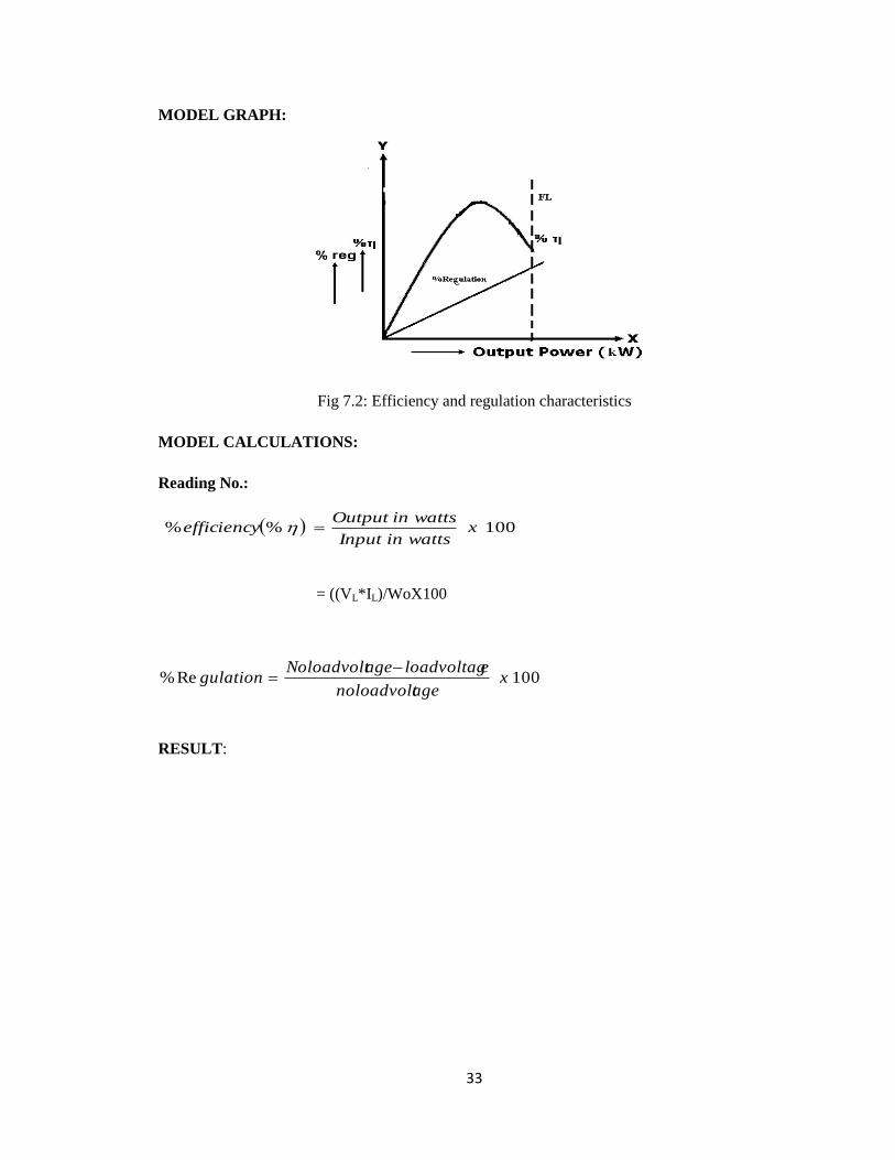
MODEL GRAPH:
Fig 7.2: Efficiency and regulation characteristics
MODEL CALCULATIONS:
Reading No.:
100%% xwattsinInput
wattsinOutputefficiency
= ((VL*IL)/WoX100
RESULT:

34
8. SCOTT CONNECTION OF TRANSFORMERS
AIM:
To convert the given 3 supply into 2 supply using Scott connection of transformers and
to find the efficiency of conversion.
APPARATUS REQUIRED:
S.No. Apparatus Type Range Quantity
CIRCUIT DIAGRAM:
Fig 8.1: Circuit diagram for scott connection
Fig 8.2: Circuit diagram for finding phase relation

35
NAME PLATE DETAILS:
a) Main Transformer:
KVA rating :
LV Side Voltage :
HV Side Voltage :
Frequency :
Number of Phases :
Type of Construction :
b) Teaser Transformer:
KVA rating :
LV Side Voltage :
HV Side Voltage :
Frequency :
Number of Phases :
Type of Construction :
PRECAUTIONS:
1. Connections must be tight and avoid wrong connections.
2. Readings are to be taken without any parallax error.
3. Initially all the knife switches should be in OPEN position.
PROCEDURE:
1. Connect the circuit diagram as shown in fig 8.1.
2. Close the TPST Switch. Note down the readings of all meters.
3. Close the DPST Switches 1&2 and vary both the loads in steps up to rated load and note
down the readings of all meters in each step. Open the TPST Switch.
4. Connect the circuit diagram as shown in fig 8.2 to verify the phase relationship of the two
phase voltages.
5. Close the TPST Switch and note down all meter readings in secondary side.
TABULATION
a) for Scott connection:
S.No. V1
(V)
I1
(A)
W1
(W)
W2
(W)
V2
(V)
I2
(A)
V3 (V) I3 (A)
Input
(kW)
Output
(kW)
%η

36
b) for phase relation:
Va (V) Vb (V)
MODEL CALCULATIONS:
For reading 2:
Input Power = (W1 + W2 )/1000
Output Power =(V2 I2 + V3 I3 )/1000
% efficiency = Output/Input*100
To Calculate Phase Relationship:
(Vb)2
=(Va)2+(Va)
2+2(Va)(Va)cos(Φ)
MODEL GRAPH:
Fig 8.3: Efficiency characteristics
RESULT:
37
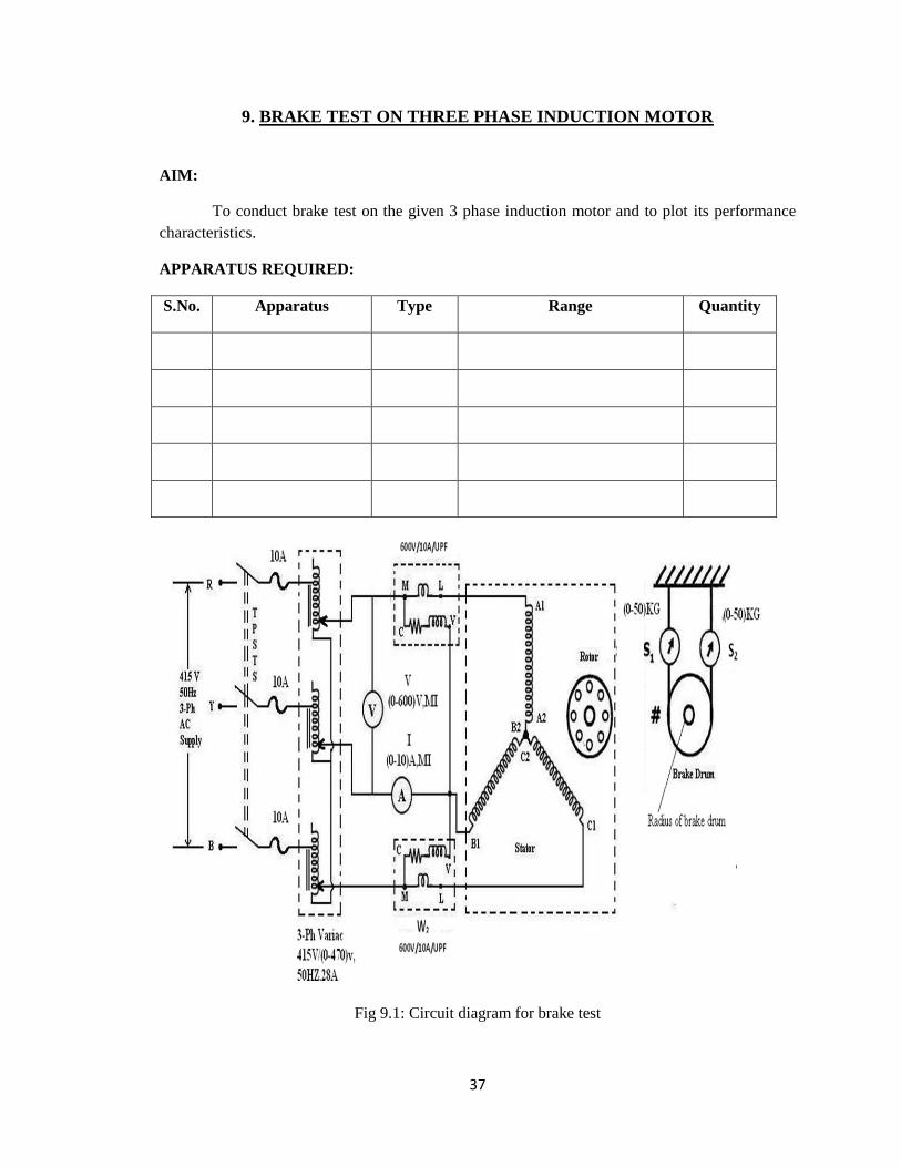
9. BRAKE TEST ON THREE PHASE INDUCTION MOTOR
AIM:
To conduct brake test on the given 3 phase induction motor and to plot its performance
characteristics.
APPARATUS REQUIRED:
S.No. Apparatus Type Range Quantity
Fig 9.1: Circuit diagram for brake test

38
NAME PLATE DETAILS:
Power :
Voltage :
Current :
Speed :
Connection :
PRECAUTIONS:
1. Avoid loose connections and wrong connections.
2. All knife switches should be open initially.
3. Readings are to be taken without any parallax error.
4. 3-Ph Variac should be in minimum output position initially.
5. There should be no load on the motor initially.
6. Circulate water in the brake drum during operation.
PROCEDURE:
1. Connect the circuit as per the Fig 9.1.
2. Observe all precautions and close the TPST Switch.
3. Apply the rated voltage to the stator windings of 3- induction motor with the help of 3 phase
variac transformer.
4. Note down the readings of all meters.
5. Load the induction motor in steps using the brake-drum arrangement. At each step note down
the readings of all meters.
OBSERVATIONS:
S.No V
(v)
I
(A)
W1
(W)
W2
(W)
S1
(Kg)
S2
(Kg)
%
Slip
Tsh
(N-m)
Output
(W)
Input
(W)
%η

39
MODEL CALCULATIONS:
for reading No 2:
Input power drawn by the motor W = (W1 + W2
Shaft Torque, Tsh = 9.81 (S1 ~ S2) R
r Radius of drum in mts.=______ m
Output power in watts = 60
2 shTN
100% XwattsinpowerInput
wattsinpoweroutputefficiency
rpmp
fXNwhereX
N
NNslip s
s
s 1500120
100%
Power factor of the induction motor LL IV
W
3cos
MODEL GRAPH:
Fig 9.2: Performance characteristics of induction motor
RESULT:

40
10. SEPERATION OF NO-LOAD LOSSES OF THREE PHASE INDUCTION MOTOR
AIM:
To separate no-load loss of a 3-phase squirrel cage Induction motor as core loss,
mechanical loss and stator copper loss.
APPARATUS:
S.No. Apparatus Type Range Quantity
CIRCUIT DIAGRAMS:
a) No-load test:
Fig 10.1: Circuit Diagram for no-load test

41
b) stator resistance test:
Fig 10.2: Circuit diagram for finding stator resistance
NAME PLATE DETAILS:
Power :
Voltage :
Current :
Speed :
Connection :
PRECAUTIONS:
1. Avoid loose connections and wrong connections.
2. All knife switches should be open initially.
3. Readings are to be taken without any parallax error.
4. 3-Ph Variac should be in minimum output position initially.
PROCEDURE:
a) No-load test:
1. Connect the circuit as per the fig 10.1.
2. Observe all precautions and close the TPST Switch.
3. Apply the rated voltage to the stator windings of 3- induction motor with the help of 3
phase variac transformer.
4. Note down the readings of wattmeter, ammeter and voltmeter on no-load.
5. Reduce the voltage gradually in steps up to motor speed becomes very low or zero and
take down all meter readings in each step.
b) stator resistance test:
1. Connect the circuit as per the fig 10.2.
2. Observe all precautions and close the DPST Switch.

42
3. Note down the readings of all the meters.
4. Vary the rheostat in steps and note down both voltmeter and ammeter readings in each
step.
OBSERVATIONS:
For no-load test:
S.No. Io
(A)
Vo
(V)
W1
(W)
W2
(W)
W1+W2
(W)
Stator
Cu loss
(W)
Constant
loss per
phase
(W)
Core
loss
per
phase
(W)
Speed
(rpm)
Io = No load Current
Vo = No load voltage
W1, W2 = Wattmeter readings
W1 + W2 = Total no load input power
For stator resistance test:
S.NO Armature Current
(I) (amps)
Armature Voltage
(V) (volts)
Armature Resistance
Rdc = V/I (ohm)
Average Resistance, Rdc=
Effective resistance per phase,Ra=1.5*Rdc

43
MODEL CALCULATIONS:
For reading no.4:
1. Input Power W = (W1 + W2) watts W
2. Stator cu loss = 3Io2Ra watts =
3. Constant loss / phase ,Wc = (W - 3Io2Ra )/3 watts
4. Core loss/phase ,Wi = (Constant loss/phase ,Wc )– (Mechanical loss, Wm)
Here the mechanical loss, Wm will be the distance from the origin to the point at where
the constant loss/phase Vs voltage curve cuts the y axis.
MODEL GRAPH:
Fig 10.3: The graph drawn between constant loss and input voltage
RESULT:

44
11. NO LOAD AND BLOCKED ROTOR TESTS ON A 3 PHASE INDUCTION MOTOR
AIM:
To draw the equivalent circuit of a given 3 phase induction motor and construct the circle
diagram by conducting No-load, blocked rotor and stator resistance tests.
APPARATUS REQUIRED:
S.No. Apparatus Type Range Quantity
CIRCUIT DIAGRAMS:
Fig 11.1: Circuit diagram for no-load test
Fig 11.2: Circuit diagram for blocked rotor test

45
Fig 11.3: Circuit diagram for finding stator resistance
NAME PLATE DETAILS:
Power :
Voltage :
Current :
Speed :
Connection :
PRECAUTIONS:
1. Avoid loose and wrong connections.
2. All knife switches should be open initially.
3. Three phase variac should be at minimum potential position initially.
4. There should be no load on the motor initially for no-load test.
5. Rotor should be blocked initially for blocked rotor test.
6. Readings should be noted without parallax errors.
PROCEDURE:
No-load test:
1. Connect the circuit as per fig 11.1.
2. Observe all precautions and close the TPST Switch.
3. Apply the rated voltage by increasing variac output gradually.
4. Note down the readings of all the meters.
Blocked rotor test:
1. Connect the circuit as per fig 11.2.
2. Observe all precautions and close the TPST Switch.
3. Apply the rated current by increasing variac output gradually.
4. Note down the readings of all the meters.

46
Measurement of Stator resistance:
1. Connect the circuit as per the fig 11.3.
2. Observe all precautions and close the DPST Switch.
3. Note down the readings of all the meters.
4. Vary the rheostat in steps and note down both voltmeter and ammeter readings in
each step.
OBSERVATION:
For no-load test: For blocked rotor test:
Speed:_______RPM Speed=_________RPM.
For stator resistance test:
S.No. Voltage (V) Current(I) Resistance(Ω)
Rdc=____ Ω.
Rac=1.6Rdc
Average
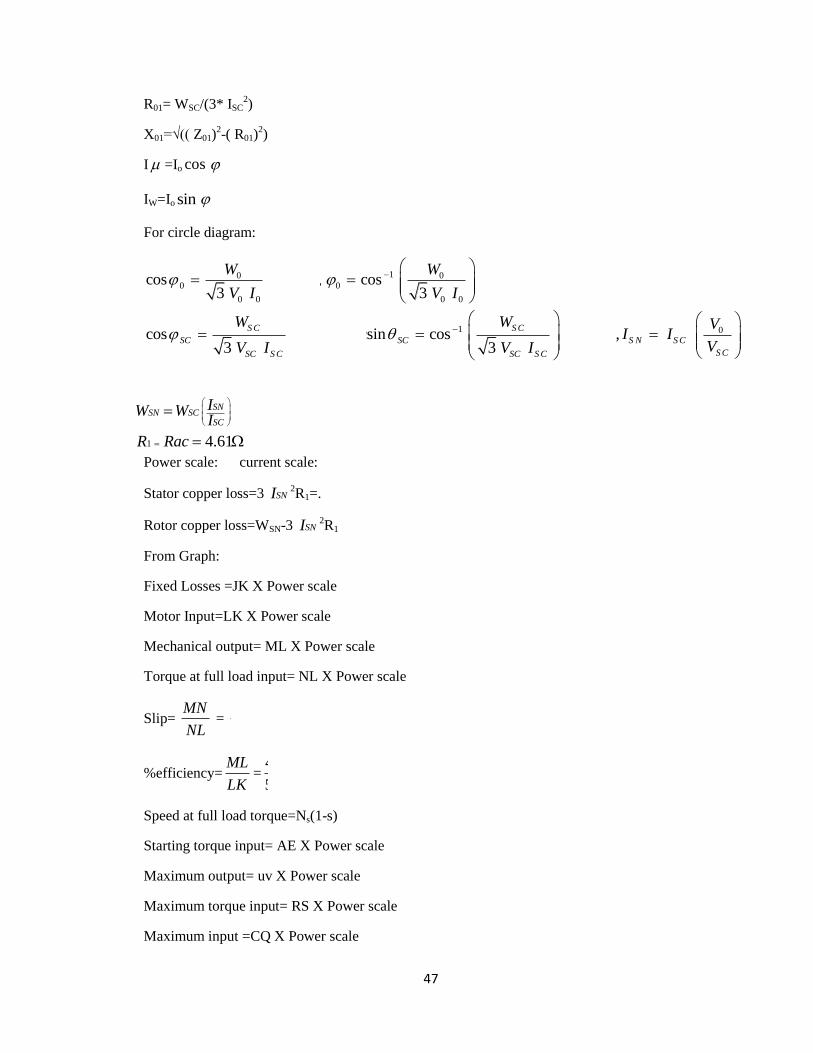
MODEL CALCULATIONS:
List of formulae:
4 1 3 1 2 2 3 10 00 0 0 0 02
120 111 1.242.32*10 , 2.987*10 , 2.978*10
3 120 415
W IG Y B Y G
V V
Z01= VSC/Isc
S.No. Vo
(V)
Io
(A)
Wo = W x M.F (w)
W1 W2
S.No. VSC
(V)
ISC
(A)
WSC = W x M.F (w)
W1 W2
(120 )/
( 4152)
5.174 x 10⁻³ Ω-1 4.62 x 10⁻³ Ω-1
47
R01= WSC/(3* ISC2)
X01=√(( Z01)2-( R01)
2)
I =Io cos
IW=Io sin
For circle diagram:
1 00 00 0
0 0 0 0
cos 0.134 , cos 82.263 3
W W
V I V I
1 0 0cos 0.589,arcsin cos 53.85 , 17.98 ,3 3
S C S C
SC SC S N S C
S CSC S C SC S C
W W VI I A
VV I V I
Power scale: current scale:
Stator copper loss=3 SNI 2R1=.
Rotor copper loss=WSN-3 SNI 2R1
From Graph:
Fixed Losses =JK X Power scale
Motor Input=LK X Power scale
Mechanical output= ML X Power scale
Torque at full load input= NL X Power scale
Slip= MN
NL =
0.6
5.0=0.12
%efficiency=ML
LK=
4.5
5.9X100=76.27%
Speed at full load torque=Ns(1-s)
Starting torque input= AE X Power scale
Maximum output= uv X Power scale
Maximum torque input= RS X Power scale
Maximum input =CQ X Power scale
1
7621.0
4.61
SNSN SC
SC
IW W WI
R Rac

48
R1l=R01-Rac
R2l=R1
l 11
S
.
CIRCLE DIAGRAM:
Fig 11.4: Circle diagram
EQUIVALENT CIRCUIT:
Fig 11.5: Equivalent diagram
RESULT:
Ro= 1441.98Ω
Xo=195.11Ω


![Application Package OF GOOD MORAL CHARACTER C.P.R. CARD [Mandatory] STATEMENT OF COMMITMENT INFECTION CONTROL [Signed] DESCRIPTION NUMBER EXP. DATE EXP. DATE EXP. DATE EXP. DATE EXP](https://img.pdfslide.us/doc/110x75/5abd9eef7f8b9a3a428bfa58/application-of-good-moral-character-cpr-card-mandatory-statement-of-commitment.jpg)